Loading ...
Loading ...
Loading ...
INSTALLATION MANUAL
INSTALLATION
8
Contents
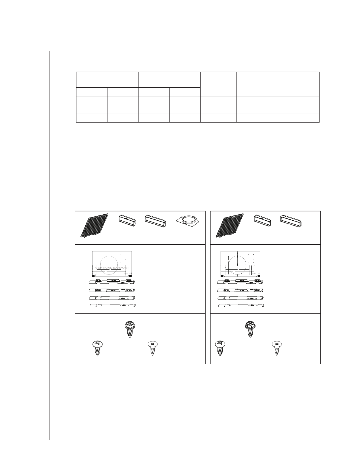
Before proceeding to the installation, check the contents of the box. If items are missing or
damaged, contact the manufacturer.
Make sure that the following items are included:
EPLEC1 Series: NPLEC1 Series:
(1) 3¼” X 10”
D
AMPER ASSEMBLY*
(1) 7” R
OUND
DUCT CONNECTOR*
(1) P
ARTS BAG*** CONTAINING:
(6) N
O. 8 X 5/8”
RD. HD.
W
OOD SCREWS
(2) INSTALLATION BRACKETS**
FOR FRAMED CABINET
(2) INSTALLATION BRACKETS**
FOR FRAMELESS CABINET
(1) TEMPLATE FOR DUCTING
(PRINTED BOTH SIDES)
(4) NO. 8-18 X 1/2”
M
ETAL SCREWS
(6) NO. 8 X 1/2”
C
OUNTERSUNK
WOOD SCREWS
EZ1 C
OMPONENTS
C
L
AB
Apoyar este borde contra la pared de atrásPlace this edge against back wall
S
A
RTICAL EX
= 3¼” x 10”
= 3¼” x 14”
RECTANGULAR DUCTING7” ROUND DUCTING
OR
Use this template for marking;do not attempt to cut out the ducting hole through it.
NOTE: These cutouts are clearance holes; they do not need to be the exact size of ducting.
= 3¼ po x 10 po
= 3¼ po x 14 po
CONDUITRECTANGULAIRECONDUITROND DE 7 PO
OU
= 3¼ pulg. x 10 pulg.
= 3¼ pulg. x 14 pulg.
CONDUCTORECTANGULARCONDUCTOREDONDO
DE
7 PULG.
O
Appuyer ce bord au mur arrière
Utiliser ce gabarit pour marquer vos repères;ne pas tenter de découper
le trou pour le conduit à travers le gabarit.
NOTE : Les découpes incluent le jeu nécessaire à l’installation; elles ne doivent pas
être du format exact des conduits.
Use esta plantilla para crear marcados;no trate de cortar el
agujero del conducto a través de la plantilla.
NOTA: To be translated in Spanish.
MARKWHERE INDICATED
FORTHE APPROPRIATE SIZE DUCT OPENING
MARQUERLES REPÈRES AUX ENDROITS INDIQUÉS SELON
LEFORMAT DE CONDUIT UTILISÉ
TITLETO BE TRANSLATED IN SPANISH
Electrical access hole center
A = single blower hood
B = double blower hood
Centre du trou pour fil
d’alimentation électrique
A = hotte ventilateur simple
B = hotte ventilateur double
To be translated in Spanish
Electrical access hole center
A = single blower hood
B = double blower hood
4¼”
10½”
14½”
8”
7½”
C
C
C
Bend template along graduated
scale when installing to framed
cabinet.
Pour une installation sous une
armoire à fond en retrait, utiliser les
lignes pour mesurer l’épaisseur du
décalage causé par le mur de
l’armoire et plier le gabarit en
conséquence.
To be translated in Spanish.
** FIND EZ1 BRACKETS ATTACHED INSIDE OF HOOD
(2) GREASE FILTERS
*** FIND PARTS BAG INSIDE OF HOOD
* FIND INSIDE OF HOOD
(1) 3¼” X 14”
D
AMPER ASSEMBLY*
(1) 3¼”
X 10”
D
AMPER ASSEMBLY*
(1) P
ARTS BAG*** CONTAINING:
(6) N
O. 8 X 5/8”
RD. HD.
W
OOD SCREWS
(2) INSTALLATION BRACKETS**
FOR FRAMED CABINET
(2) INSTALLATION BRACKETS**
FOR FRAMELESS CABINET
(1) TEMPLATE FOR DUCTING
(PRINTED BOTH SIDES)
(4) NO. 8-18 X 1/2”
M
ETAL SCREWS
(6) NO. 8 X 1/2”
C
OUNTERSUNK
WOOD SCREWS
EZ1 C
OMPONENTS
C
L
AB
Apoyar este borde contra la pared de atrásPlace this edge against back wall
VERTICAL EXHAUST
V
RTICAL EX
= 3¼” x 10”
= 3¼” x 14”
RECTANGULAR DUCTING7” ROUND DUCTING
OR
Use this template for marking;do not attempt to cut out the ducting hole through it.
NOTE: These cutouts are clearance holes; they do not need to be the exact size of ducting.
= 3¼ po x 10 po
= 3¼ po x 14 po
CONDUITRECTANGULAIRECONDUITROND DE 7 PO
OU
= 3¼ pulg. x 10 pulg.
= 3¼ pulg. x 14 pulg.
CONDUCTORECTANGULARCONDUCTOREDONDO
DE
7 PULG.
O
Appuyer ce bord au mur arrière
Utiliser ce gabarit pour marquer vos repères;ne pas tenter de découper
le trou pour le conduit à travers le gabarit.
NOTE : Les découpes incluent le jeu nécessaire à l’installation; elles ne doivent pas
être du format exact des conduits.
Use esta plantilla para crear marcados;no trate de cortar el
agujero del conducto a través de la plantilla.
NOTA: To be translated in Spanish.
MARKWHERE INDICATED
FORTHE APPROPRIATE SIZE DUCT OPENING
MARQUERLES REPÈRES AUX ENDROITS INDIQUÉS SELON
LEFORMAT DE CONDUIT UTILISÉ
TITLETO BE TRANSLATED IN SPANISH
Electrical access hole center
A = single blower hood
B = double blower hood
Centre du trou pour fil
d’alimentation électrique
A = hotte ventilateur simple
B = hotte ventilateur double
To be translated in Spanish
Electrical access hole center
A = single blower hood
B = double blower hood
4¼”
10½”
14½”
8”
7½”
C
C
C
Bend template along graduated
scale when installing to framed
cabinet.
Pour une installation sous une
armoire à fond en retrait, utiliser les
lignes pour mesurer l’épaisseur du
décalage causé par le mur de
l’armoire et plier le gabarit en
conséquence.
To be translated in Spanish.
** FIND EZ1 BRACKETS ATTACHED INSIDE OF HOOD
(2) GREASE FILTERS
*** FIND PARTS BAG INSIDE OF HOOD
* FIND INSIDE OF HOOD
(1) 3¼” X 14”
D
AMPER ASSEMBLY*
Maximum Duct Lengths Recommended
to Achieve 80% Exhaust Efficiency
HORIZONTAL MAXIMUM
DUCT LENGTHS
VERTICAL MAXIMUM
DUCT LENGTHS
7” ROUND
MAXIMUM
DUCT LENGTH
ROOF OR
WALL CAP
WITH DAMPER
ELBOW(S)*
(90° AND/OR 45°)
3¼” X 10” 3¼” X 14” 3¼” X 10” 3¼” X 14”
44 ft. 76 ft. 39 ft. 72 ft. 89 ft. 1 0
35 ft. 66 ft. 30 ft. 62 ft. 79 ft. 1 1
26 ft. 56 ft. 22 ft. 52 ft. 70 ft. 1 2
* Standard elbows with 1” internal radius.
NOTE: 6" round ducting is possible but may reduce exhaust efficiency.
Loading ...
Loading ...
Loading ...