Before using your new product, please read these instructions to prevent any damage.
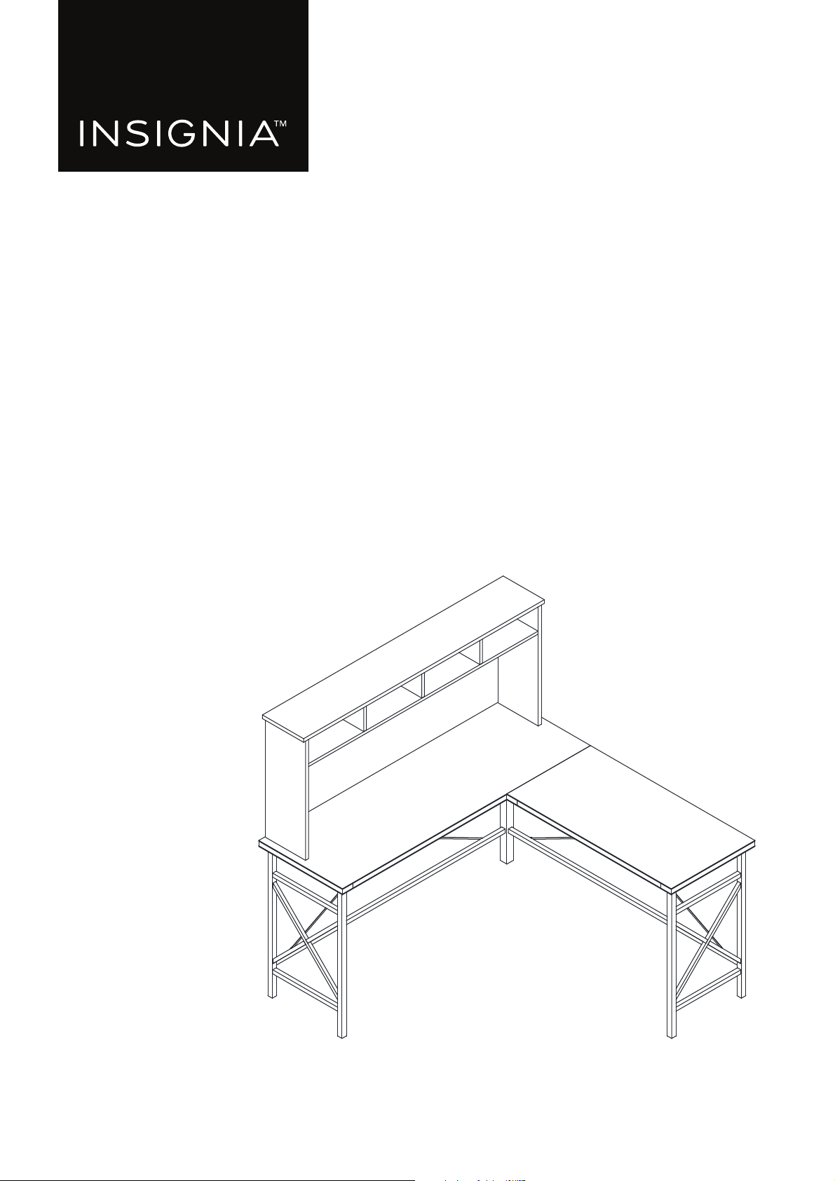
USER GUIDE
L-Shaped
Computer Desk
NS-ODL3

www.insigniaproducts.com
2
Contents
Introduction . . . . . . . . . . . . . . . . . . . . . . . . . . . . . . . . . . . . . . . . . . . . . . . . . . . . . . . . . . . . . . . . . . . . . . . . . . . . . . . . . . . . . . . . . . . . . . . . . . . . . .2
Safety information . . . . . . . . . . . . . . . . . . . . . . . . . . . . . . . . . . . . . . . . . . . . . . . . . . . . . . . . . . . . . . . . . . . . . . . . . . . . . . . . . . . . . . . . . . . . . . . . 3
Features . . . . . . . . . . . . . . . . . . . . . . . . . . . . . . . . . . . . . . . . . . . . . . . . . . . . . . . . . . . . . . . . . . . . . . . . . . . . . . . . . . . . . . . . . . . . . . . . . . . . . . . . . . 3
Dimensions. . . . . . . . . . . . . . . . . . . . . . . . . . . . . . . . . . . . . . . . . . . . . . . . . . . . . . . . . . . . . . . . . . . . . . . . . . . . . . . . . . . . . . . . . . . . . . . . . . . . 3
Parts included . . . . . . . . . . . . . . . . . . . . . . . . . . . . . . . . . . . . . . . . . . . . . . . . . . . . . . . . . . . . . . . . . . . . . . . . . . . . . . . . . . . . . . . . . . . . . . . . . 4
Hardware included. . . . . . . . . . . . . . . . . . . . . . . . . . . . . . . . . . . . . . . . . . . . . . . . . . . . . . . . . . . . . . . . . . . . . . . . . . . . . . . . . . . . . . . . . . . . . 5
Tools needed . . . . . . . . . . . . . . . . . . . . . . . . . . . . . . . . . . . . . . . . . . . . . . . . . . . . . . . . . . . . . . . . . . . . . . . . . . . . . . . . . . . . . . . . . . . . . . . . . . 5
Preparing to assemble your desk . . . . . . . . . . . . . . . . . . . . . . . . . . . . . . . . . . . . . . . . . . . . . . . . . . . . . . . . . . . . . . . . . . . . . . . . . . . . . . . . . .5
Understanding cam locks and cam-lock screws . . . . . . . . . . . . . . . . . . . . . . . . . . . . . . . . . . . . . . . . . . . . . . . . . . . . . . . . . . . . . . . . . 6
Assembling your desk. . . . . . . . . . . . . . . . . . . . . . . . . . . . . . . . . . . . . . . . . . . . . . . . . . . . . . . . . . . . . . . . . . . . . . . . . . . . . . . . . . . . . . . . . . . . .7
STEP 1: Insert wooden dowels into the hutch divider panels. . . . . . . . . . . . . . . . . . . . . . . . . . . . . . . . . . . . . . . . . . . . . . . . . . . . . 7
STEP 2: Insert wooden dowels into the bottom hutch panel . . . . . . . . . . . . . . . . . . . . . . . . . . . . . . . . . . . . . . . . . . . . . . . . . . . . . 8
STEP 3: Connect the hutch divider panels to the bottom hutch panel . . . . . . . . . . . . . . . . . . . . . . . . . . . . . . . . . . . . . . . . . . . . 9
STEP 4: Insert wooden dowels into the back hutch panel . . . . . . . . . . . . . . . . . . . . . . . . . . . . . . . . . . . . . . . . . . . . . . . . . . . . . . .10
STEP 5: Connect the back hutch panel to the hutch assembly. . . . . . . . . . . . . . . . . . . . . . . . . . . . . . . . . . . . . . . . . . . . . . . . . . .11
STEP 6: Insert wooden dowels and cam-lock screws into the left and right hutch panels . . . . . . . . . . . . . . . . . . . . . . . . .12
STEP 7: Connect the left and right hutch panels to the hutch assembly . . . . . . . . . . . . . . . . . . . . . . . . . . . . . . . . . . . . . . . . .13
STEP 8: Insert cam-lock screws into the top hutch panel . . . . . . . . . . . . . . . . . . . . . . . . . . . . . . . . . . . . . . . . . . . . . . . . . . . . . . . .14
STEP 9: Connect the top hutch panel to the hutch assembly . . . . . . . . . . . . . . . . . . . . . . . . . . . . . . . . . . . . . . . . . . . . . . . . . . . .15
STEP 10: Connect the hutch assembly to the main desktop . . . . . . . . . . . . . . . . . . . . . . . . . . . . . . . . . . . . . . . . . . . . . . . . . . . . .16
STEP 11: Attach support bars to the side leg assembly. . . . . . . . . . . . . . . . . . . . . . . . . . . . . . . . . . . . . . . . . . . . . . . . . . . . . . . . . .17
STEP 12: Attach the center leg to the side leg assembly supports . . . . . . . . . . . . . . . . . . . . . . . . . . . . . . . . . . . . . . . . . . . . . . .18
STEP 13: Attach support bars to the main leg assembly. . . . . . . . . . . . . . . . . . . . . . . . . . . . . . . . . . . . . . . . . . . . . . . . . . . . . . . . .19
STEP 14: Connect the main leg assembly and side leg assembly . . . . . . . . . . . . . . . . . . . . . . . . . . . . . . . . . . . . . . . . . . . . . . . .20
STEP 15: Secure the main leg assembly and side leg assembly . . . . . . . . . . . . . . . . . . . . . . . . . . . . . . . . . . . . . . . . . . . . . . . . . .21
STEP 16: Attach the desktops to the leg assembly . . . . . . . . . . . . . . . . . . . . . . . . . . . . . . . . . . . . . . . . . . . . . . . . . . . . . . . . . . . . . .22
STEP 17: Attach the cross bars to your desk . . . . . . . . . . . . . . . . . . . . . . . . . . . . . . . . . . . . . . . . . . . . . . . . . . . . . . . . . . . . . . . . . . . .23
STEP 18: Secure your desk to the wall . . . . . . . . . . . . . . . . . . . . . . . . . . . . . . . . . . . . . . . . . . . . . . . . . . . . . . . . . . . . . . . . . . . . . . . . . .24
Cleaning your desk. . . . . . . . . . . . . . . . . . . . . . . . . . . . . . . . . . . . . . . . . . . . . . . . . . . . . . . . . . . . . . . . . . . . . . . . . . . . . . . . . . . . . . . . . . . . . . .25
Specifications . . . . . . . . . . . . . . . . . . . . . . . . . . . . . . . . . . . . . . . . . . . . . . . . . . . . . . . . . . . . . . . . . . . . . . . . . . . . . . . . . . . . . . . . . . . . . . . . . . . .25
Troubleshooting . . . . . . . . . . . . . . . . . . . . . . . . . . . . . . . . . . . . . . . . . . . . . . . . . . . . . . . . . . . . . . . . . . . . . . . . . . . . . . . . . . . . . . . . . . . . . . . . .25
ONE-YEAR LIMITED WARRANTY. . . . . . . . . . . . . . . . . . . . . . . . . . . . . . . . . . . . . . . . . . . . . . . . . . . . . . . . . . . . . . . . . . . . . . . . . . . . . . . . . . .26
Introduction
Congratulations on your purchase of a high-quality Insignia product. Your NS-ODL3 represents the state of the art in desk
design and is designed for reliable and trouble-free performance.
3
L-Shaped Computer Desk
www.insigniaproducts.com
Safety information
WARNING: Cancer and reproductive harm. www.p65warnings.ca.gov
WARNING: Please use your furniture correctly and safely. Improper use can cause safety hazards, or damage to
your furniture or household items.
• This product is intended to hold maximum weight indicated:
• Desktop: Up to 100 lbs. (45.4 kg)
• Hutch: Up to 20 lbs. (9.1 kg)
• Shelf: Up to 5 lbs. (2.3 kg)
• Do not allow children to climb or jump on furniture due to possible accident, injury, or death.
• Never push or pull furniture that is not designed with casters as this may cause injury or damage to the
unit.
Features
• Metal legs help to provide stability
• Features a hutch to allow for storage or for items to be displayed
• Desktop supports up to 100 lbs., hutch supports up to 20 lbs., and shelf supports up to 5 lbs.
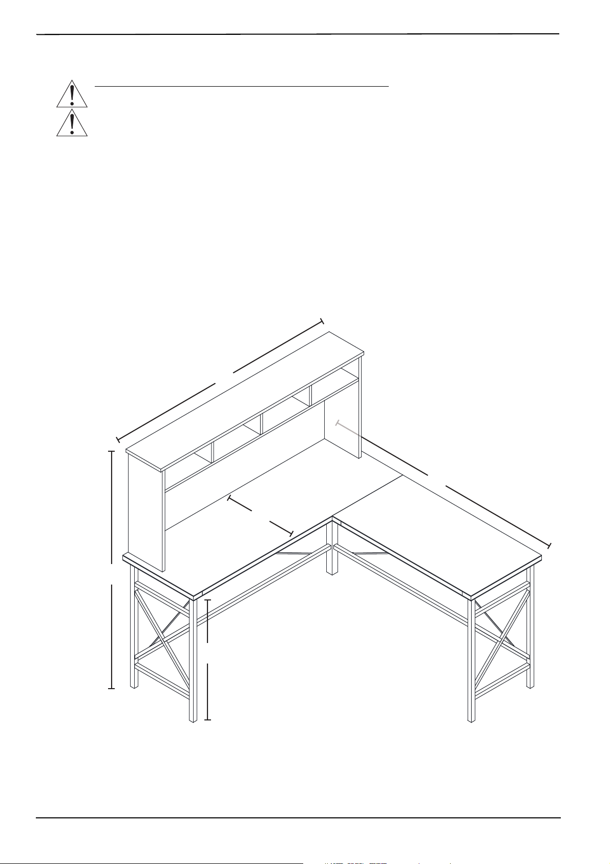
Dimensions
54.4 in. (138.3 cm)
56 in. (142.3 cm)
56 in. (142.3 cm)
18.9 in. (48 cm)
28.4 in. (72.1 cm)
4
www.insigniaproducts.com
Parts included
Note: Parts are labeled on the side of each panel.
1
Top hutch panel
2
Back hutch panel
3
Bottom hutch panel
4
Hutch divider panels (3)
5
Left hutch panel
6
Right hutch panel
8
Side desktop
9
Main leg assembly
10
Side leg assembly
11
Main back support bar
12
Main front support bar
13
Bottom support bars (2)
14
Side back support bar
15
Side front support bar
16
Center leg
7
Main desktop
17
Cross bars (2)
5
L-Shaped Computer Desk
www.insigniaproducts.com
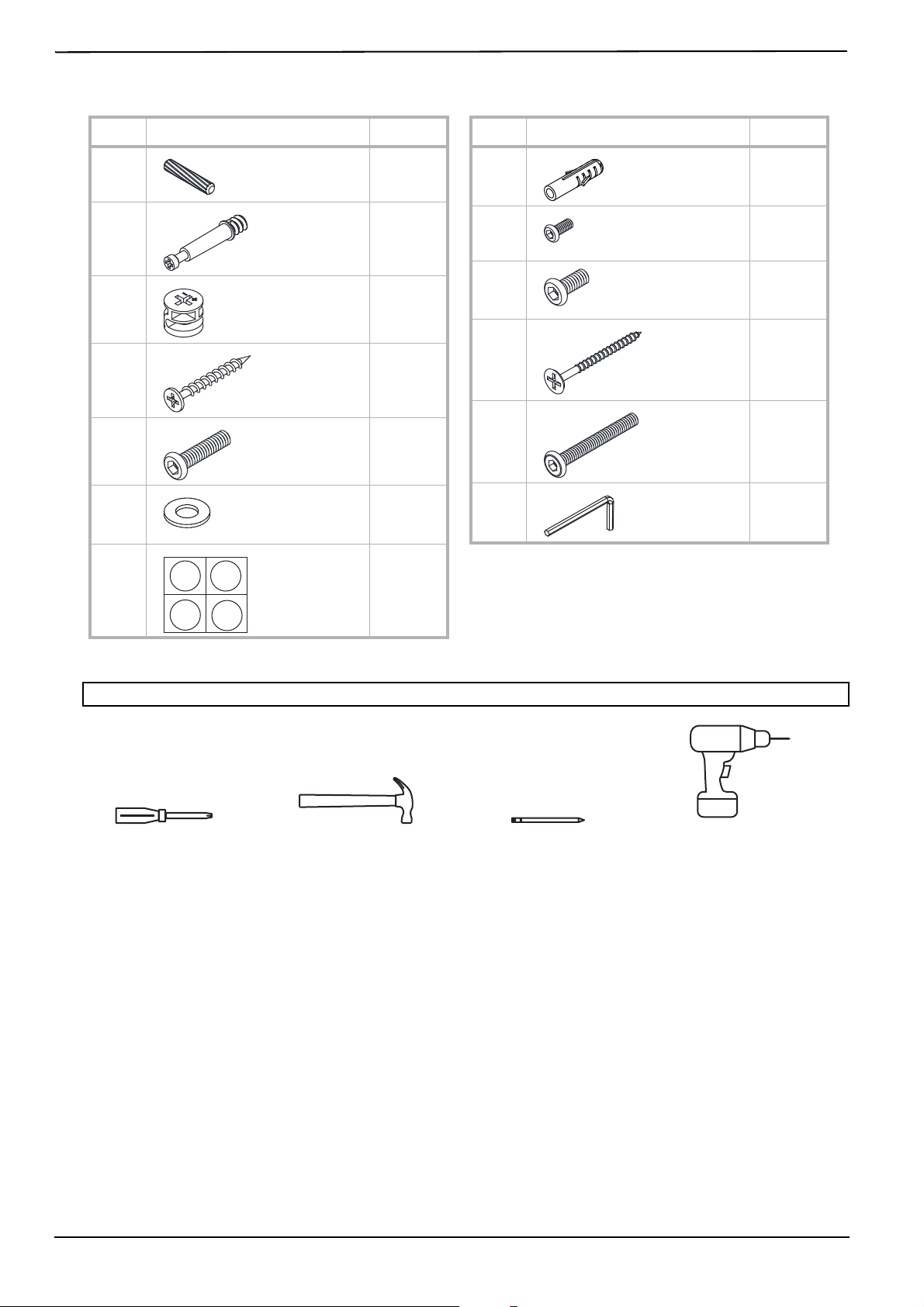
Hardware included
Tools needed
Preparing to assemble your desk
1 Follow the assembly instructions carefully.
2 Make sure that all parts and hardware are included.
3 To prevent product damage, assemble your desk on top of the box.
4 Have another person help you with lifting and assembly.
5 For the best results, do not fully tighten the screws until you have assembled all the other parts.
CAUTION: Do not use a drill to assemble your desk. The drill should only be used to secure your desk to the wall (step 18).
LABEL HARDWARE QTY.
A26
B19
C19
D3
E13
F13
G16
Wooden dowels
Cam-lock
screws
Cam locks
3.8 × 45 mm
screws
M6 × 30 mm
bolts
Washers
Screw covers
LABEL HARDWARE QTY.
H2
I8
J10
K6
L7
M1
Anchors
M5 × 15 mm
bolts
M6 × 15 mm
bolts
5 × 50 mm
screws
M6 × 50 mm
bolts
Hex wrench
Drill with M8 bit
(For wall mounting only)HammerPhillips #2 screwdriver
Pencil
6
www.insigniaproducts.com
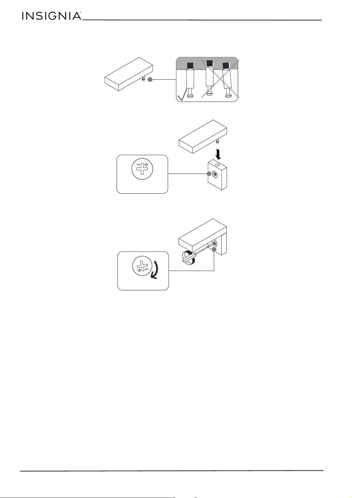
Understanding cam locks and cam-lock screws
1 Screw the cam-lock screws (B) into each piece with a Phillips screwdriver. Make sure that they are straight and flush
with each panel.
2 Align the cam lock (C) arrow toward to the hole, then insert the cam-lock screw into the hole of the cam lock.
3 Use a Phillips
screwdriver to turn the cam lock (C) clockwise until it is locked. The locked position is about a 1/2 turn
(160°–185°). Do not overturn the cam lock.
7
L-Shaped Computer Desk
www.insigniaproducts.com
Assembling your desk
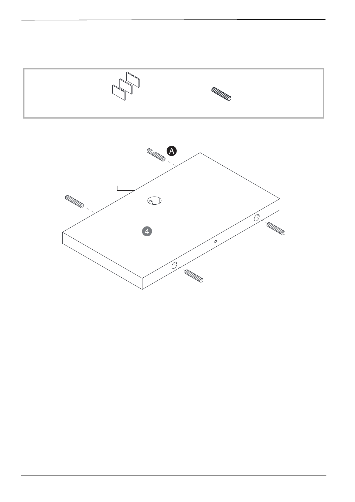
STEP 1: Insert wooden dowels into the hutch divider panels
You n e ed:
1 Insert 12 wooden dowels (A) into the edges of the three hutch divider panels (4). Be careful not to insert the dowels
into the cam-lock screw holes.
A
Wooden dowels (12)
4
Hutch divider panels (3)
Cam-lock screw hole.
Do NOT insert dowels here.
8
www.insigniaproducts.com
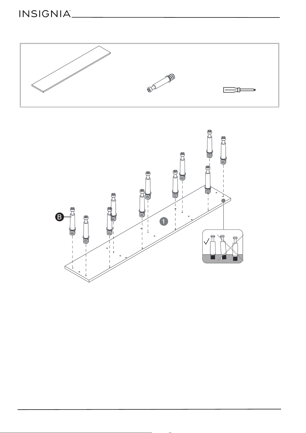
STEP 2: Insert wooden dowels into the bottom hutch panel
You n e ed:
1 Insert four wooden dowels (A) into the edges of the bottom hutch panel (3).
A
Wooden dowels (4)
3
Bottom hutch panel
9
L-Shaped Computer Desk
www.insigniaproducts.com
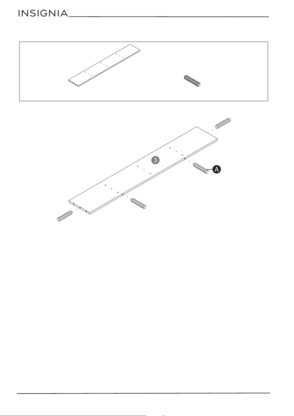
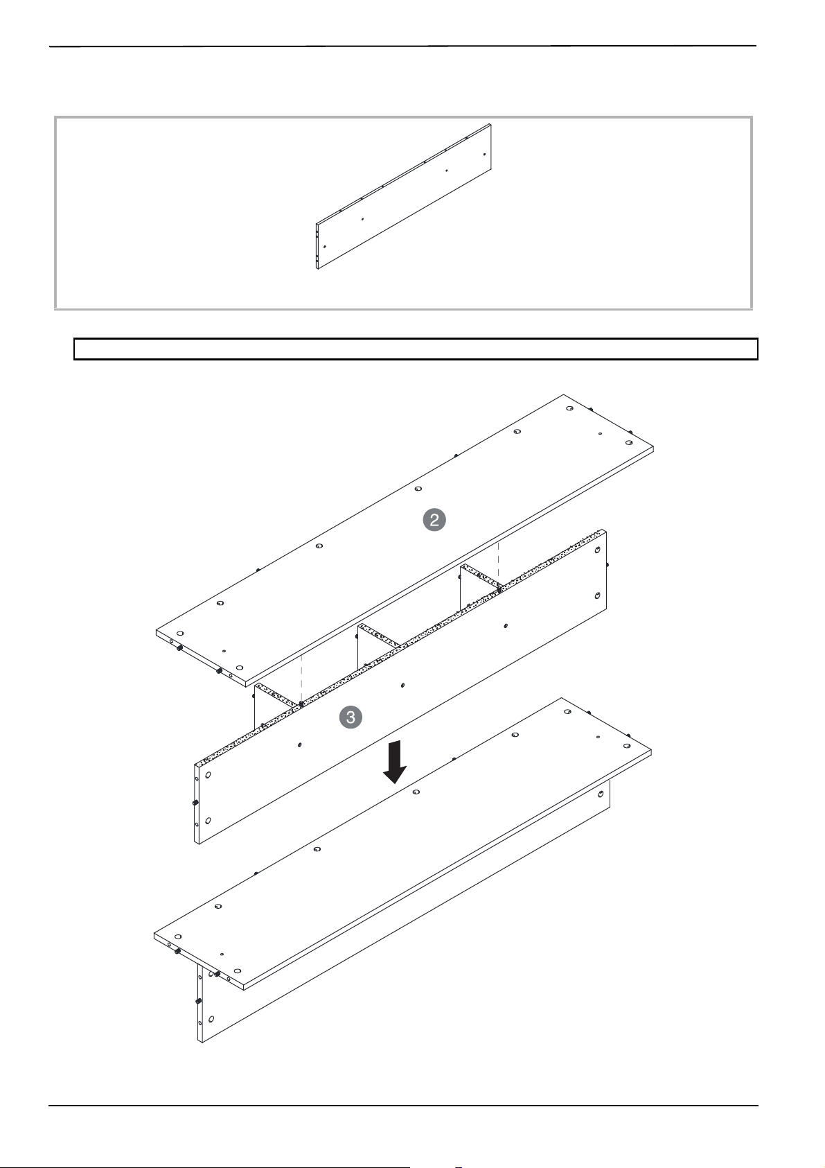
STEP 3: Connect the hutch divider panels to the bottom hutch panel
You n e ed:
1 Align the wooden dowels on a hutch divider panel (4) with the holes in the bottom hutch panel (3). Make sure that
the edges of the panels are flush with each other so the divider panel edge is not raised (as shown).
2 Secure the divider panel with a 3.8 × 45 mm screw (D) and a Phillips screwdriver.
3 Cover the head of the screw with a screw cover (G).
4 Repeat steps 1–3 to connect the other two hutch divider panels. This is the hutch assembly.
T
D
3.8 × 45 mm screws (3)
G
Screw covers (3)
Phillips screwdriver
3
Bottom hutch panel
4
Hutch divider panels (3)
10
www.insigniaproducts.com
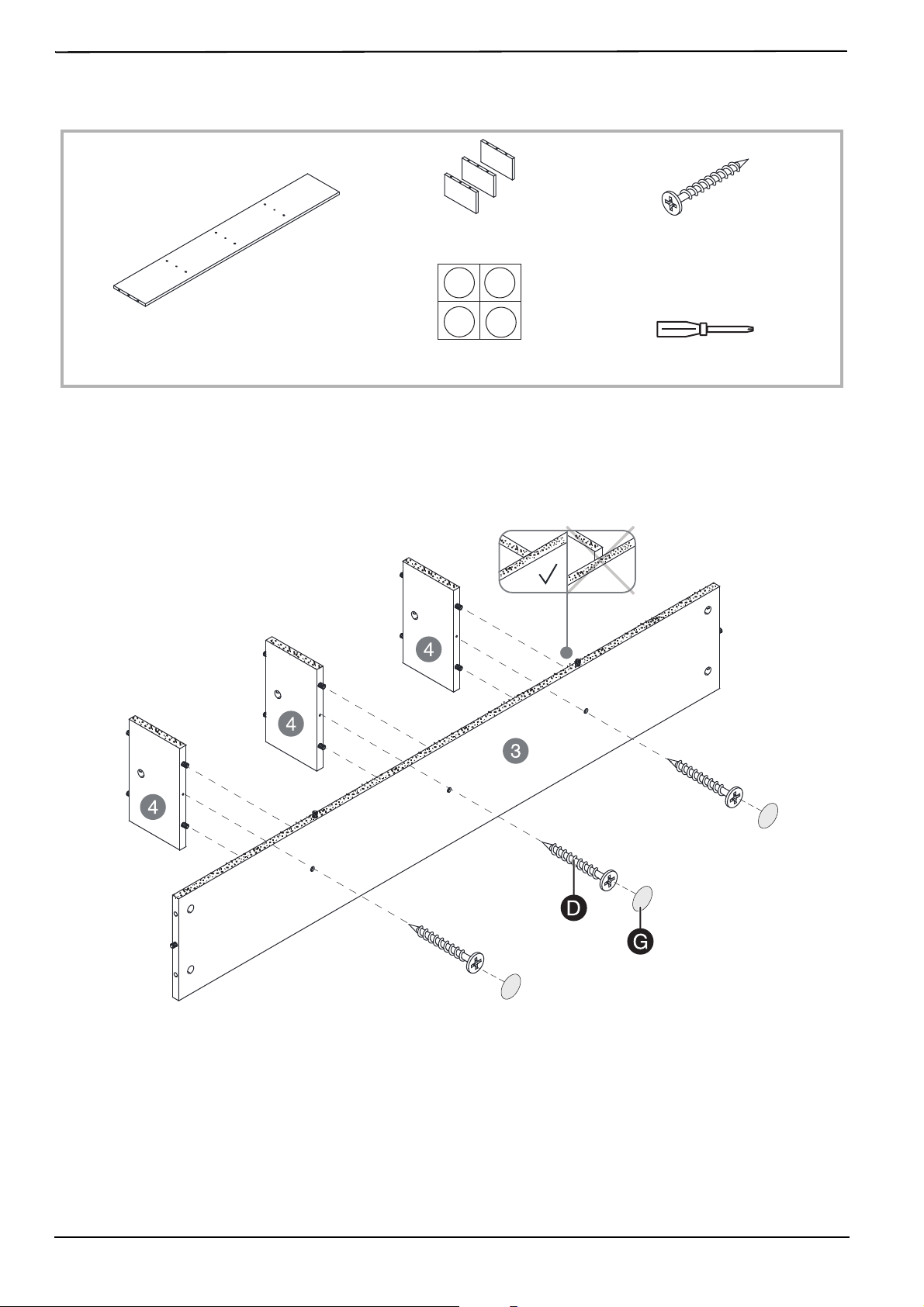
STEP 4: Insert wooden dowels into the back hutch panel
You n e ed:
1 [Insert six wooden dowels (A) into the edges of the back hutch panel (2).
A
Wooden dowels (6)
2
Back hutch panel
11
L-Shaped Computer Desk
www.insigniaproducts.com
STEP 5: Connect the back hutch panel to the hutch assembly
You n e ed:
1 Align the wooden dowels on the hutch assembly with the holes in the back hutch panel (2).
Tip: Add a drop of glue (not included) onto the end of each dowel before inserting it into the hole.
2
Back hutch panel
12
www.insigniaproducts.com
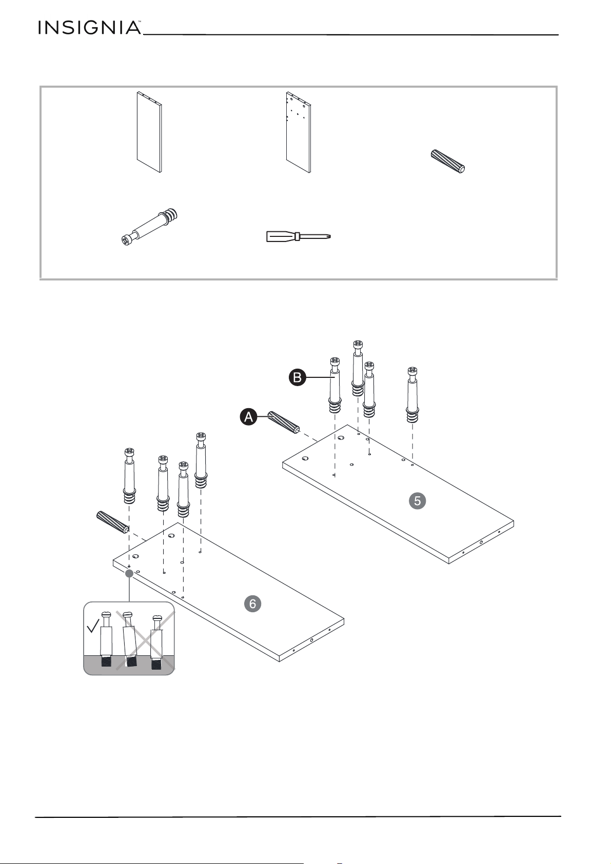
STEP 6: Insert wooden dowels and cam-lock screws into the left and right hutch panels
You n e ed:
1 Insert two wooden dowels (A) into the edges of the left hutch panel (5) and right hutch panel (6).
2 Screw eight cam-lock screws (B) into the left and right hutch panels with a Phillips
screwdriver. Make sure that the
cam-lock screws are straight and flush with each panel.
T
B
Cam-lock screws (8)
Phillips screwdriver
5
Left hutch panel
6
Right hutch panel
A
Wooden dowels (2)
13
L-Shaped Computer Desk
www.insigniaproducts.com
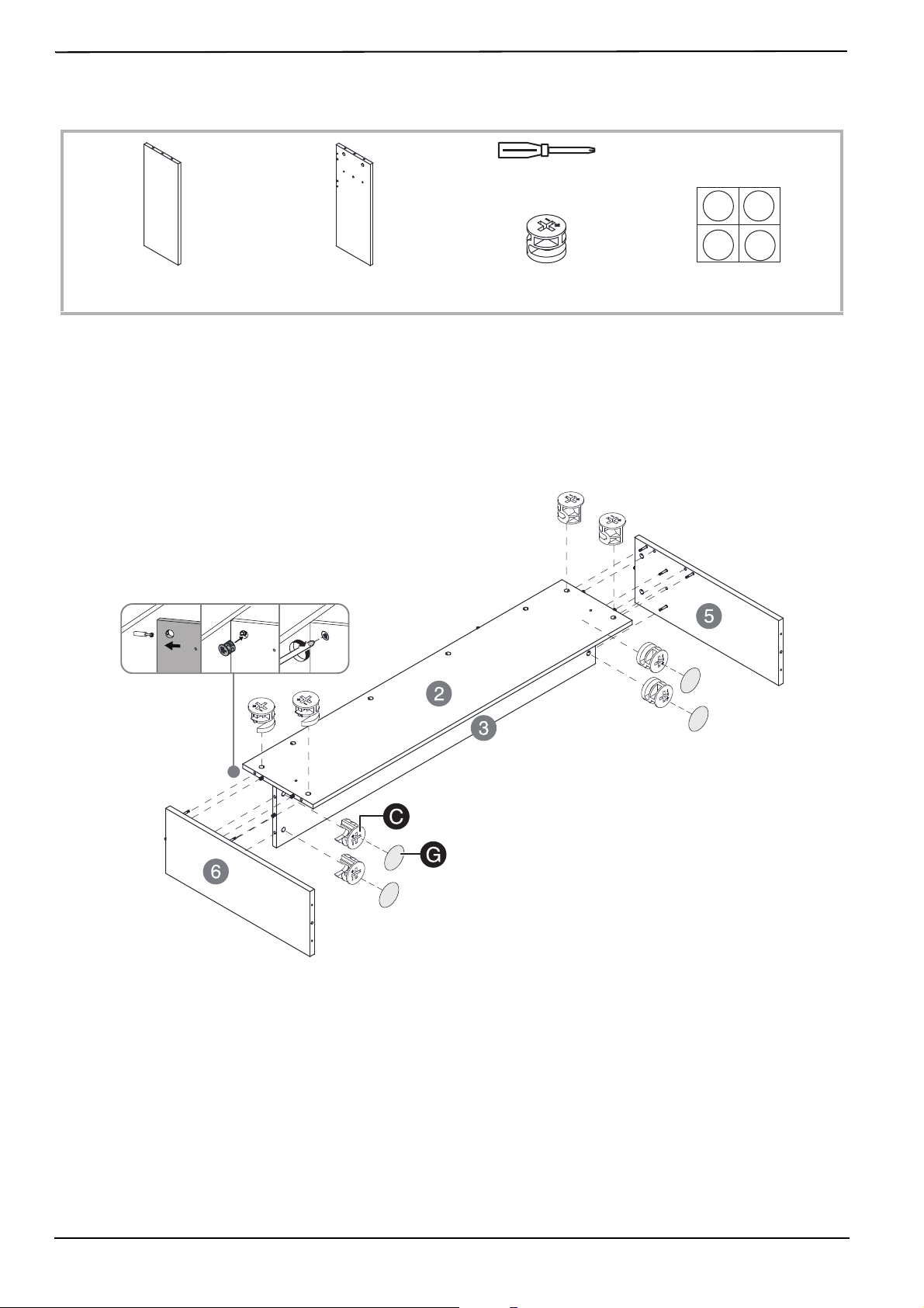
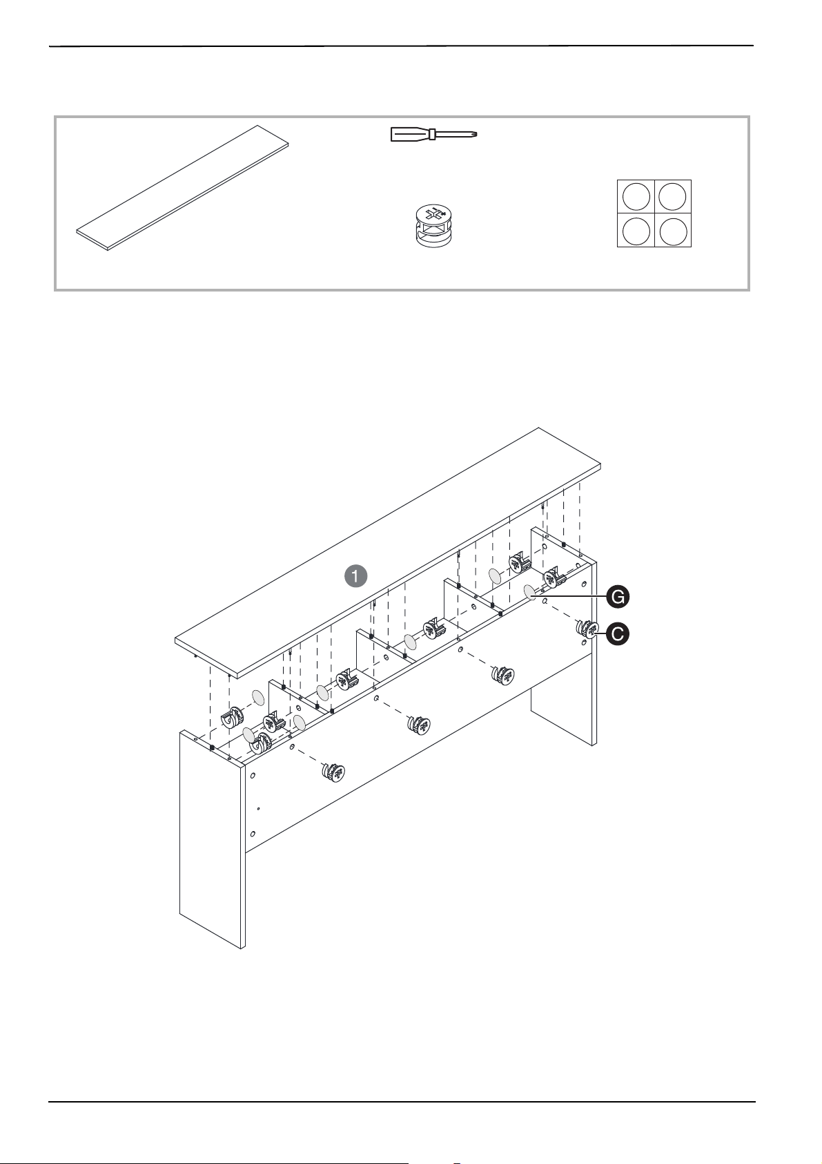
STEP 7: Connect the left and right hutch panels to the hutch assembly
You n e ed:
1 To connect the left hutch panel (5) to the hutch assembly, align the wooden dowels and cam-lock screws with the
holes in the panels.
2 Insert four cam locks (C) into the hutch assembly (as shown). Make sure that the cam lock arrows are pointing
toward their corresponding cam-lock screw holes.
3 Turn the cam locks clockwise with a Phillips screwdriver until they are fully tightened (about 160° to 185°).
4 Cover the four cam locks on the bottom hutch panel (3) with screw covers (G).
5 Repeat steps 1–3 to connect the right hutch panel (6).
T
C
Cam locks (8)
Phillips screwdriver
5
Left hutch panel
6
Right hutch panel
G
Screw covers (4)
14
www.insigniaproducts.com
STEP 8: Insert cam-lock screws into the top hutch panel
You n e ed:
1 Screw 11 cam-lock screws (B) into the top hutch panel (1) with a Phillips screwdriver. Make sure that the cam-lock
screws are straight and flush.
T
Phillips screwdriver
1
Top hutch panel
B
Cam-lock screws (11)
15
L-Shaped Computer Desk
www.insigniaproducts.com
STEP 9: Connect the top hutch panel to the hutch assembly
You n e ed:
1 To connect the top hutch panel (1) to the hutch assembly, align the wooden dowels and cam-lock screws with the
holes in the panels.
2 Insert 11 cam locks (C) into the hutch assembly (as shown). Make sure that the cam lock arrows are pointing toward
their corresponding cam-lock screw holes.
3 Turn the cam locks clockwise with a Phillips screwdriver until they are fully tightened (about 160° to 185°).
4 Cover the seven cam locks inside the hutch assembly with screw covers (G).
T
Phillips screwdriver
1
Top hutch panel
C
Cam locks (11)
G
Screw covers (7)
16
www.insigniaproducts.com
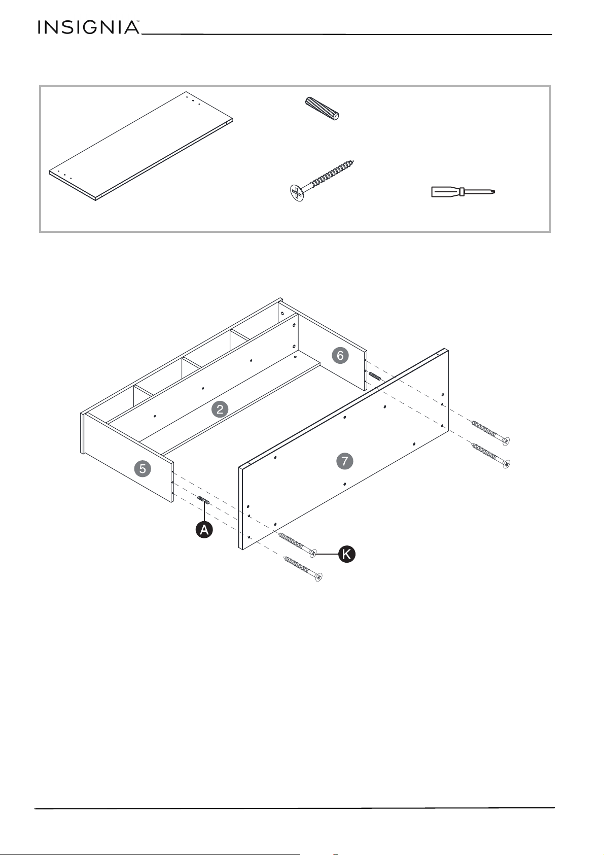
STEP 10: Connect the hutch assembly to the main desktop
You n e ed:
1 Insert two wooden dowels (A) into the bottom edges of the left hutch panel (5) and right hutch panel (6).
2 Align the wooden dowels and screw holes in the hutch assembly with the holes in the main desktop (7).
3 Secure the main desktop with four 5 × 50 mm screws (K) and a Phillips screwdriver.
Phillips screwdriverK
5 × 50 mm screws (4)
7
Main desktop
A
Wooden dowels (2)
17
L-Shaped Computer Desk
www.insigniaproducts.com
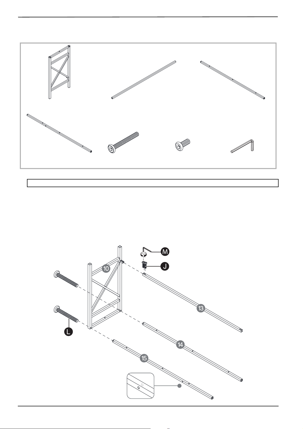
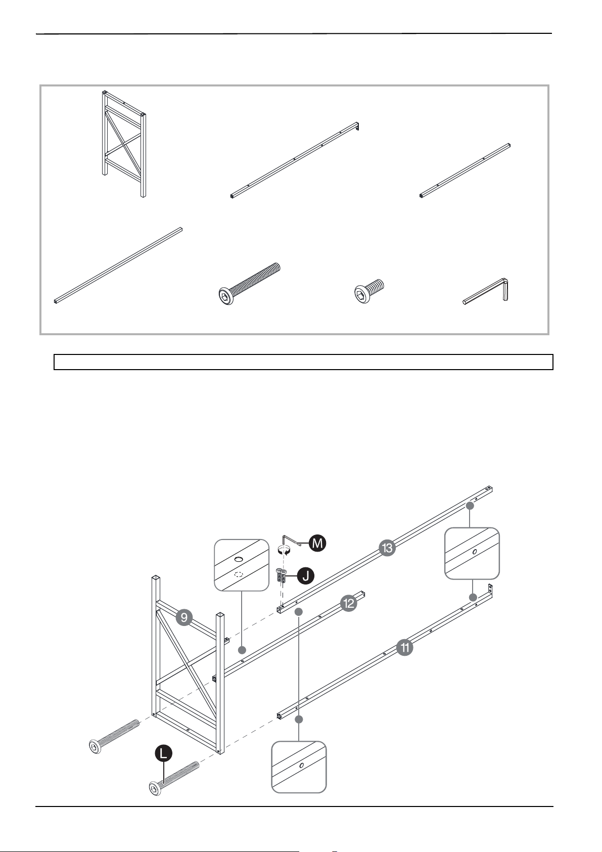
STEP 11: Attach support bars to the side leg assembly
You n e ed:
1 Align the side front support bar (15) with the top/front hole in the side leg assembly (10), then secure with a M6 ×
50 mm bolt (L) and a hex wrench (M). Make sure that the holes in the side front support bar (15) face the front and
back of your desk (as shown).
2 Align the side back support bar (14) with the top/back hole in the side leg assembly (10), then secure with a M6 ×
50 mm bolt (L) and a hex wrench (M). Make sure that the outermost holes in the side back support bar (14) face the
back of your desk (as shown).
3 Align the bottom support bar (13) with the bottom/back bracket in the side leg assembly (10), then secure with
two M6 × 15 mm bolts (J) and a hex wrench (M). Make sure that the holes in the bottom support bar (13) face the
back of your desk (as shown).
Note: To make assembly easier, do not lock the bolts tightly until you have assembled all other parts.
J
M6 × 15 mm bolts (2)
M
Hex wrench
L
M6 × 50 mm bolts (2)
10
Side leg assembly
13
Bottom support bar (1)
14
Side back support bar
15
Side front support bar
TOP/FRONT
BOTTOM/BACK
18
www.insigniaproducts.com
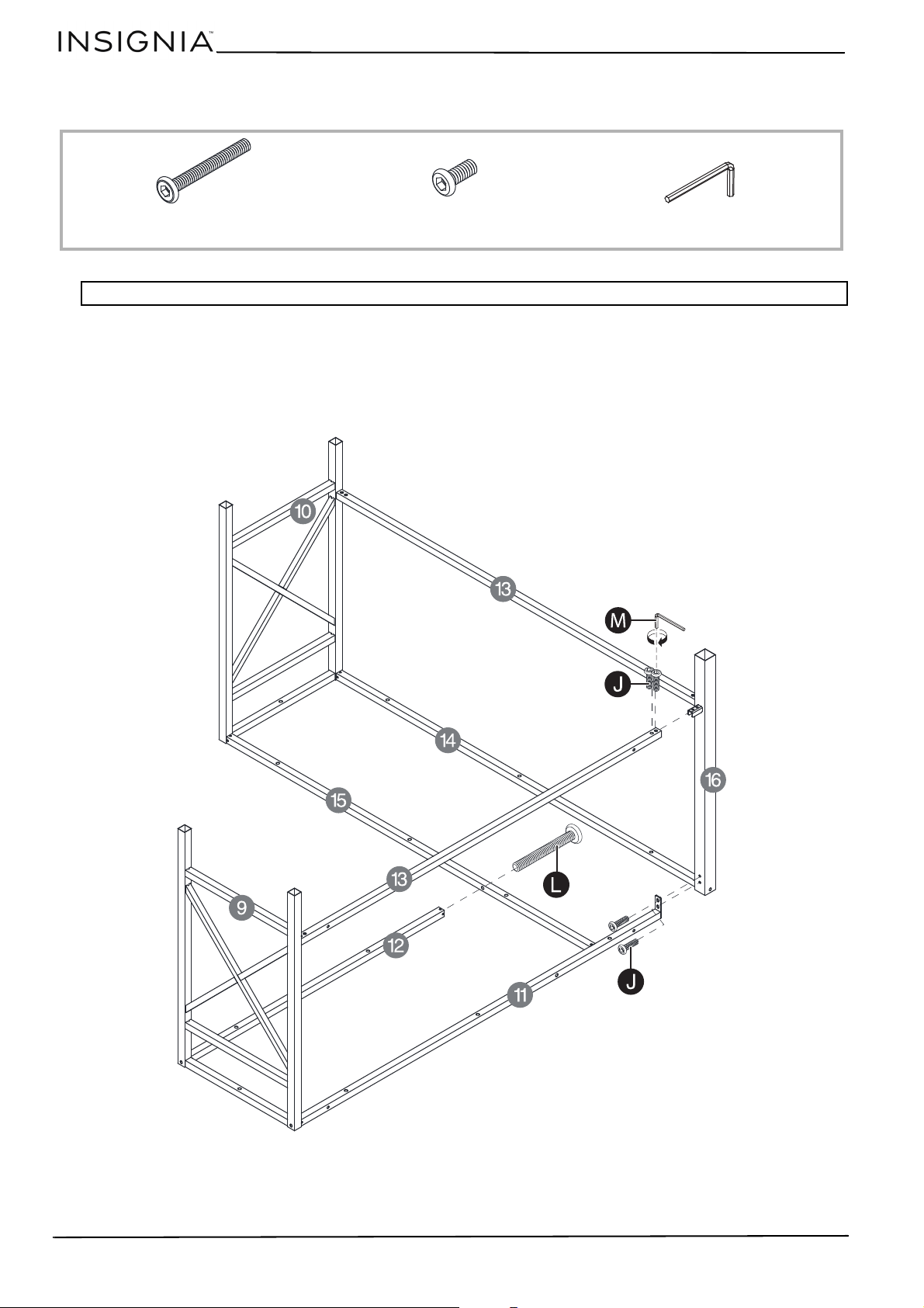
STEP 12: Attach the center leg to the side leg assembly supports
You n e ed:
1 Align the bracket on the center leg (16) with the bottom support bar (13), then secure with two M6 × 15 mm
bolts (J) and a hex wrench (M). Make sure that the second bracket on the center leg faces the front of your desk (as
shown).
2 Align the holes in the center leg (16) and side back support bar (14), then secure with a M6 × 50 mm bolt (L) and
hex wrench (M).
16
Center leg
L
M6 × 50 mm bolt (1)
J
M6 × 15 mm bolts (2)
M
Hex wrench
TOP/FRONT
BOTTOM/BACK
19
L-Shaped Computer Desk
www.insigniaproducts.com
STEP 13: Attach support bars to the main leg assembly
You n e ed:
1 Align the main front support bar (12) with the top/front hole in the main leg assembly (9), then secure with a M6 ×
50 mm bolt (L) and a hex wrench (M). Make sure that the holes in the main front support bar (12) face up and down
(as shown).
2 Align the main back support bar (11) with the top/back hole in the main leg assembly (9), then secure with a M6 ×
50 mm bolt (L) and a hex wrench (M). Make sure that the outermost holes in the main back support bar (11) face
the back of your desk (as shown).
3 Align the bottom support bar (13) with the bottom/back bracket in the main leg assembly (9), then secure with two
M6 × 15 mm bolts (J) and a hex wrench (M). Make sure that the holes in the bottom support bar (13) face the back
of your desk (as shown).
Note: To make assembly easier, do not lock the bolts tightly until you have assembled all other parts.
9
Main leg assembly
11
Main back support bar
12
Main front support bar
L
M6 × 50 mm bolts (2)
J
M6 × 15 mm bolts (2)
M
Hex wrench
13
Bottom support bar (1)
TOP/FRONT
TOP/BACK
20
www.insigniaproducts.com
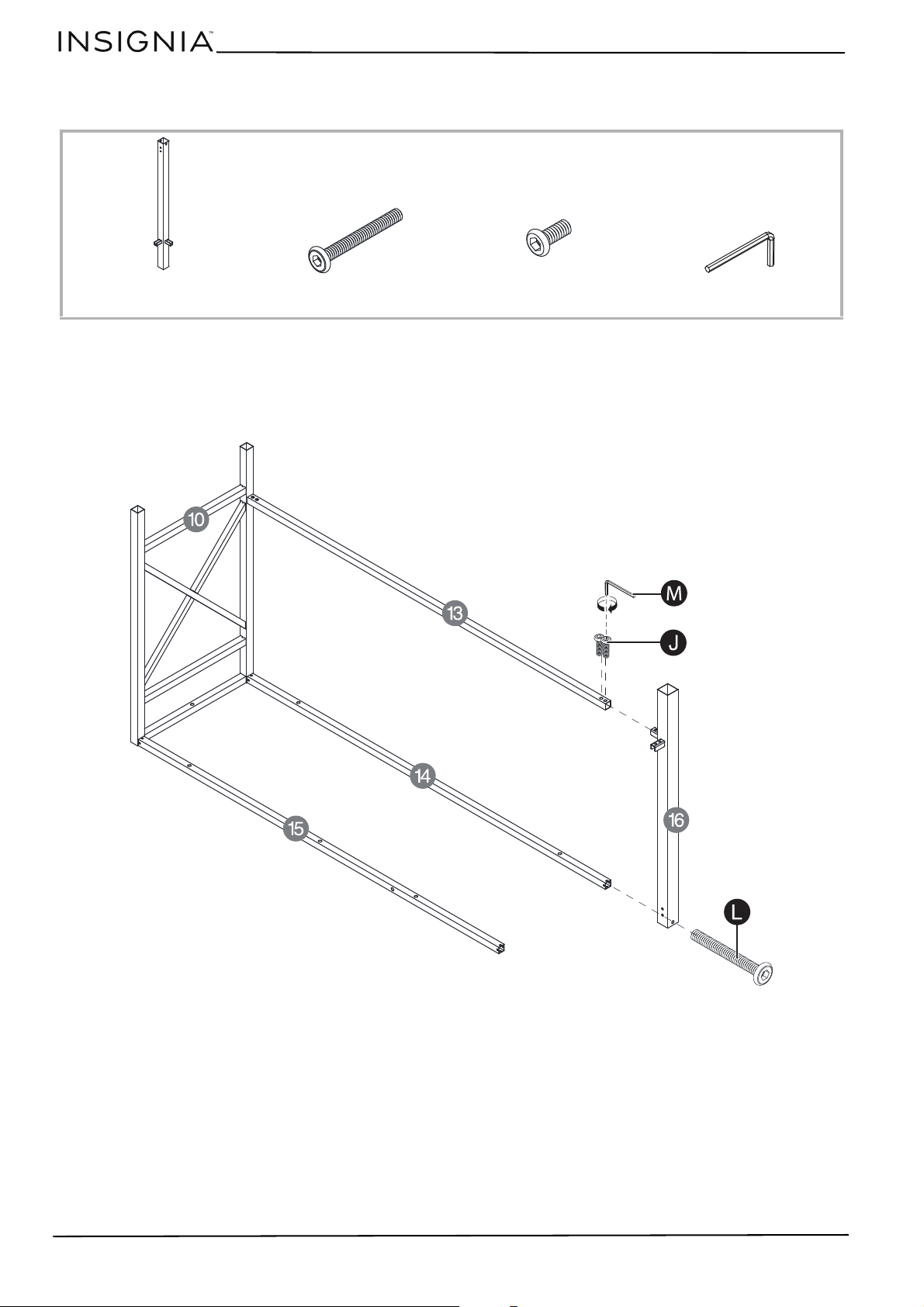
STEP 14: Connect the main leg assembly and side leg assembly
You n e ed:
1 Align the bottom support bar (13) connected to the main leg assembly with the bracket on the center leg (16),
then secure with two M6 × 15 mm bolts (J) and a hex wrench (M).
2 Align the main back support bar (11) with the holes at the top of the center leg (16), then secure with two
M6 × 15 mm bolts (J) and a hex wrench (M).
3 Align the end of the main front support bar (12) with the hole on the side front support bar (15), then secure with a
M6 × 50 mm bolt (L) and a hex wrench (M).
Note: To make assembly easier, do not lock the bolts tightly until you have assembled all other parts.
L
M6 × 50 mm bolt
J
M6 × 15 mm bolts (4)
M
Hex wrench
TOP/FRONT
BOTTOM/BACK
21
L-Shaped Computer Desk
www.insigniaproducts.com
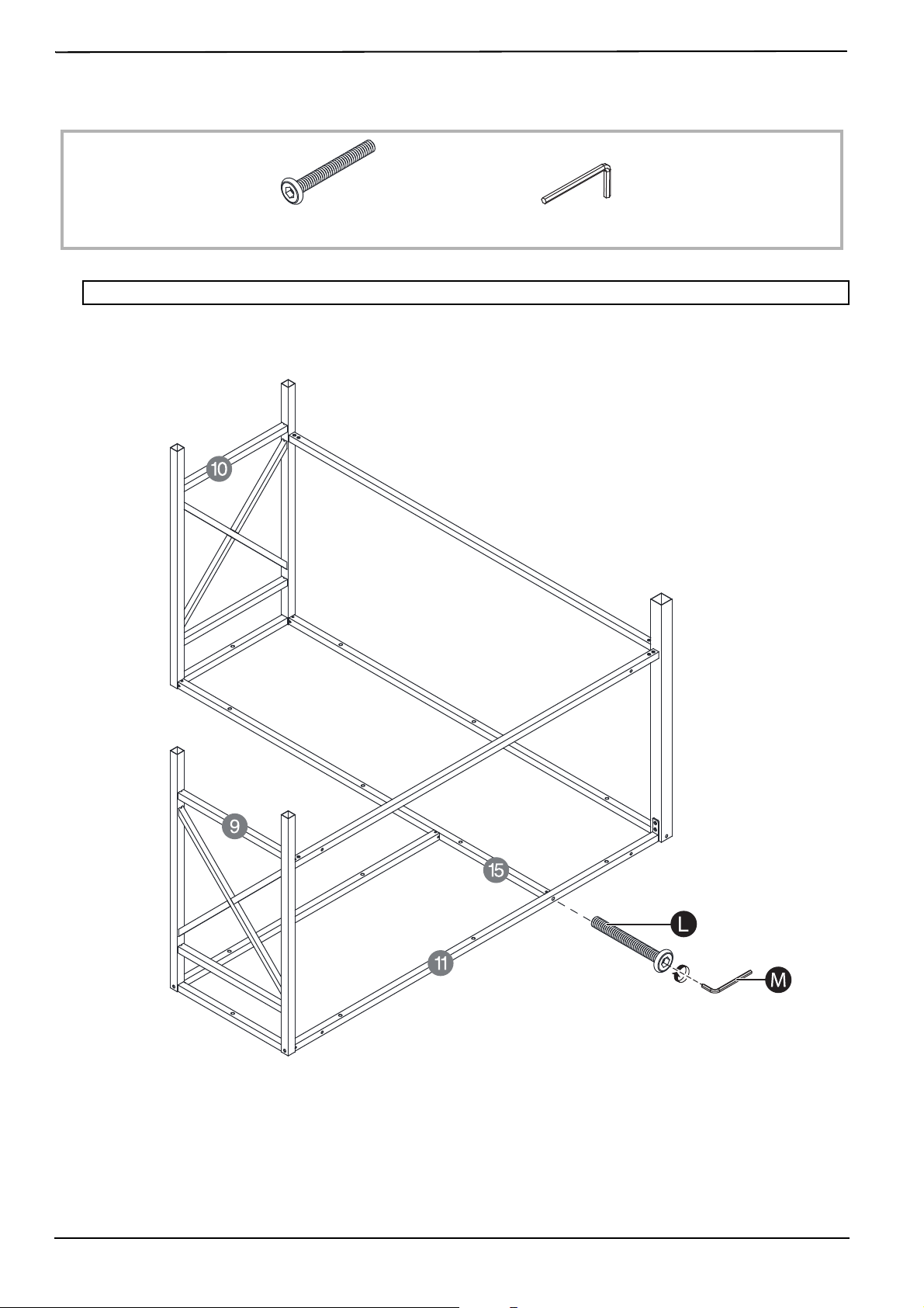
STEP 15: Secure the main leg assembly and side leg assembly
You n e ed:
1 Align the end of the side front support bar (15) with the hole on the main back support bar (11), then secure with a
M6 × 50 mm bolt (L) and a hex wrench (M).
2 Have someone help you lift the leg assembly into an upright position.
Note: To make assembly easier, do not lock the bolts tightly until you have assembled all other parts.
L
M6 × 50 mm bolt
M
Hex wrench
TOP/FRONT
BOTTOM/BACK
22
www.insigniaproducts.com
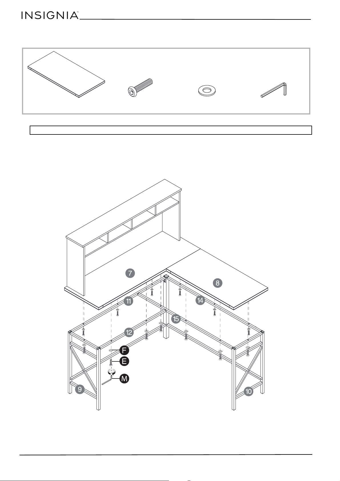
STEP 16: Attach the desktops to the leg assembly
You n e ed:
1 Have someone help you lift the main desktop (7) on top of the main leg assembly. Make sure that the holes
underneath the main desktop align with the holes in the leg assembly.
2 Secure the main desktop (7) with eight M6 × 30 mm bolts (E), eight washers (F), and a hex wrench (M).
3 Align the holes underneath the side desktop (8) with the holes in the side leg assembly.
4 Secure the side desktop (8) with five M6 × 30 mm bolts (E), five washers (F), and a hex wrench (M).
Note: To make assembly easier, do not lock the bolts tightly until you have assembled all other parts.
E
M6 × 30 mm bolts (13)
F
Washers (13)
8
Side desktop
M
Hex wrench
23
L-Shaped Computer Desk
www.insigniaproducts.com
STEP 17: Attach the cross bars to your desk
You n e ed:
1 Secure each set of cross bars (17) to the back of the leg assemblies with M5 × 15 mm bolts (I) and the hex
wrench (M).
I
M5 × 15 mm bolts (8)
M
Hex wrench
17
Cross bars (2)
24
www.insigniaproducts.com
STEP 18: Secure your desk to the wall
You n e ed:
1 Move your desk where you want to place it. The hutch should be against a wall.
2 Find the anchor holes in the hutch’s back panel, then mark their location on your wall with a pencil.
3 Move your desk away from the wall.
4 Drill two M8 (7.1 mm) holes in the wall at the places you marked with a pencil.
5 Insert the anchors (H) into the holes and gently tap them with a hammer until they are flush with the wall.
6 Push your desk back against the wall, then secure with two 5 × 50 mm screws (K) and a Phillips screwdriver.
7 Cover the heads of the screws with the screw covers (G).
WARNING:
• DO NOT SKIP THIS STEP. Securing your desk protects children and pets from accidental tip-overs and injury.
•The included screws (K) and anchors (H) are intended for securing your desk to drywall only. If your wall is made of a different
material, you must purchase appropriate anchors and screws separately.
H
Anchors (2)
Drill with M8 bit
(For wall mounting only)
HammerPhillips #2 screwdriver
K
5 × 50 mm screws (2)
G
Screw covers (2)
Pencil
25
L-Shaped Computer Desk
www.insigniaproducts.com
Cleaning your desk
• Clean the surface of your desk with a duster or damp cloth only.
• Do not use abrasive cleaners.
Specifications
Troubleshooting
Dimensions (H × W × D) 54.4 × 56 × 56 in. (138.3 × 142.3 × 142.3 cm)
Weight 89.3 lbs. (40.5 kg)
Maximum supported weight Desktop: 100 lbs. (45.4 kg)
Hutch: 20 lbs. (9.1 kg)
Shelf: 5 lbs. (2.3 kg)
PROBLEM POSSIBLE SOLUTIONS
My desk wobbles Place your desk on a solid, sturdy surface. Carpet may cause your desk to wobble.
A piece won’t fit Loosen screws to let the pieces move more freely. After your desk is assembled, fully
tighten the screws.

26
www.insigniaproducts.com
ONE-YEAR LIMITED WARRANTY
Definitions:
The Distributor* of Insignia branded products warrants to you, the original purchaser of this new Insignia-branded product (“Product”), that the
Product shall be free of defects in the original manufacturer of the material or workmanship for a period of one (1) year from the date of your
purchase of the Product (“Warranty Period”).
For this warranty to apply, your Product must be purchased in the United States or Canada from a Best Buy branded retail store or Online at
www.bestbuy.com or www.bestbuy.ca and is packaged with this warranty statement.
How long does the coverage last?
The Warranty Period lasts for 1 year (365 days) from the date you purchased the Product. Your purchase date is printed on the receipt you received
with the Product.
What does this warranty cover?
During the Warranty Period, if the original manufacture of the material or workmanship of the Product is determined to be defective by an
authorized Insignia repair center or store personnel, Insignia will (at its sole option): (1) repair the Product with new or rebuilt parts; or (2) replace
the Product at no charge with new or rebuilt comparable products or parts. Products and parts replaced under this warranty become the property
of Insignia and are not returned to you. If service of Products or parts are required after the Warranty Period expires, you must pay all labor and
parts charges. This warranty lasts as long as you own your Insignia Product during the Warranty Period. Warranty coverage terminates if you sell or
otherwise transfer the Product.
How to obtain warranty service?
If you purchased the Product at a Best Buy retail store location or from a Best Buy Online website (www.bestbuy.com or www.bestbuy.ca), please
take your original receipt and the Product to any Best Buy store. Make sure that you place the Product in its original packaging or packaging that
provides the same amount of protection as the original packaging.
To obtain warranty service, in the United States and Canada call 1-877-467-4289. Call agents may diagnose and correct the issue over the phone.
Where is the warranty valid?
This warranty is valid only in the United States and Canada at Best Buy branded retail stores or websites to the original purchaser of the product in
the country where the original purchase was made.
What does the warranty not cover?
This warranty does not cover:
• Food, beverage, and or medicine loss/spoilage.
• Customer instruction/education
•Installation
•Set up adjustments
• Cosmetic damage
• Damage due to weather, lightning, and other acts of God, such as power surges
• Accidental damage
•Misuse
•Abuse
•Negligence
• Commercial purposes/use, including but not limited to use in a place of business or in communal areas of a multiple dwelling condominium
or apartment complex, or otherwise used in a place of other than a private home.
• Modification of any part of the Product, including the antenna
• Display panel damaged by static (non-moving) images applied for lengthy periods (burn-in).
• Damage due to incorrect operation or maintenance
• Connection to an incorrect voltage or power supply
• Attempted repair by any person not authorized by Insignia to service the Product
• Products sold “as is” or “with all faults”
• Consumables, including but not limited to batteries (i.e. AA, AAA, C etc.)
• Products where the factory applied serial number has been altered or removed
• Loss or Theft of this product or any part of the product
• Display panels containing up to three (3) pixel failures (dots that are dark or incorrectly illuminated) grouped in an area smaller than one
tenth (1/10) of the display size or up to five (5) pixel failures throughout the display. (Pixel based displays may contain a limited number of
pixels that may not function normally.)
• Failures or Damage caused by any contact including but not limited to liquids, gels or pastes.
REPAIR REPLACEMENT AS PROVIDED UNDER THIS WARRANTY IS YOUR EXCLUSIVE REMEDY FOR BREACH OF WARRANTY.
INSIGNIA SHALL NOT BE LIABLE FOR ANY INCIDENTAL OR CONSEQUENTIAL DAMAGES FOR THE BREACH OF ANY
EXPRESS OR IMPLIED WARRANTY ON THIS PRODUCT, INCLUDING, BUT NOT LIMITED TO, LOST DATA, LOSS OF USE OF
YOUR PRODUCT, LOST BUSINESS OR LOST PROFITS. INSIGNIA PRODUCTS MAKES NO OTHER EXPRESS WARRANTIES
WITH RESPECT TO THE PRODUCT, ALL EXPRESS AND IMPLIED WARRANTIES FOR THE PRODUCT, INCLUDING BUT NOT
LIMITED TO ANY IMPLIED WARRANTIES OF AND CONDITIONS OF MERCHANTABILITY AND FITNESS FOR A PARTICULAR
PURPOSE, ARE LIMITED IN DURATION TO THE WARRANTY PERIOD SET FORTH ABOVE AND NO WARRANTIES, WHETHER
EXPRESS OR IMPLIED, WILL APPLY AFTER THE WARRANTY PERIOD. SOME STATES, PROVINCES AND JURISDICTIONS DO
NOT ALLOW LIMITATIONS ON HOW LONG AN IMPLIED WARRANTY LASTS, SO THE ABOVE LIMITATION MAY NOT APPLY
TO YOU. THIS WARRANTY GIVES YOU SPECIFIC LEGAL RIGHTS, AND YOU MAY ALSO HAVE OTHER RIGHTS, WHICH VARY
FROM STATE TO STATE OR PROVINCE TO PROVINCE.
Contact Insignia:
1-877-467-4289
www.insigniaproducts.com
INSIGNIA is a trademark of Best Buy and its affiliated companies.
*Distributed by Best Buy Purchasing, LLC
7601 Penn Ave South, Richfield, MN 55423 U.S.A
©2022 Best Buy. All rights reserved.

For product inquiries, please contact us with the information below:
1-877-467-4289
www.insigniaproducts.com
INSIGNIA is a trademark of Best Buy and its affiliated companies.
Distributed by Best Buy Purchasing, LLC
7601 Penn Ave South, Richfield, MN 55423 U.S.A.
©2022 Best Buy. All rights reserved.
V2 ENGLISH
22-0241