ENGLISH | 1
Congratulations on purchasing the Celestron Smart DewHeater
and Controller 2x. This controller delivers “smart” and efficient
power usage for up to two of your telescope system’s dew
heaters plus another 12V DC device—while also providing cable
management for your setup. When you plug your dew heaters
into the controller, one cable connects everything to your power
source, while another connects the setup to your PC, if desired.
If you prefer not to connect to a PC, simply plug your dew heaters
into the controller and power it on. The controller will automatically
monitor the ambient temperature and humidity using its integrated
environmental sensor. The thermistor port monitors the lens’s
temperature and provides only enough power to prevent dew.
If you’re using battery power, this “smart” system significantly
reduces the heaters’ power consumption, extending battery life. If
you would like to manually adjust settings or monitor data, connect
to a PC or your Celestron mount’s hand control.
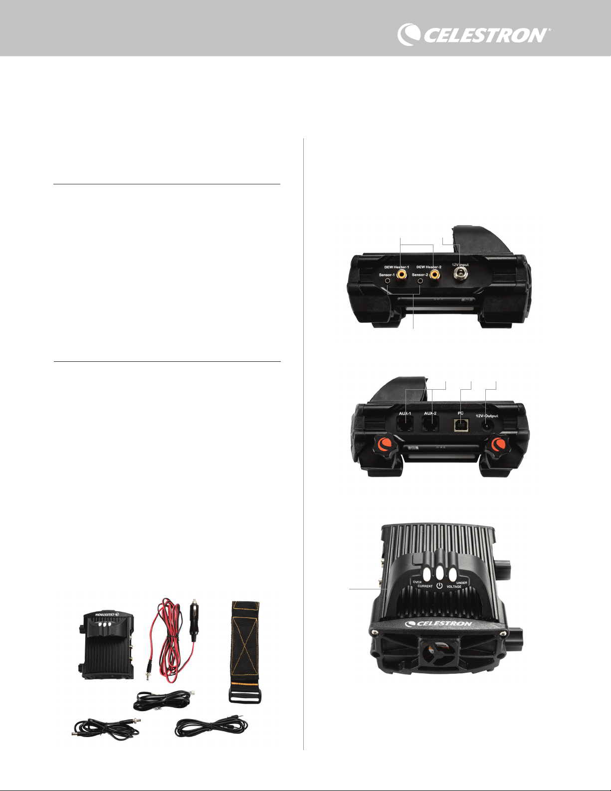
1. Parts List
2. Controller Overview
TABLE OF CONTENTS
Fig 1 – All included items
Refer to Figure 2 for an overview of the input jacks, output ports, and
features of the Smart DewHeater Controller 2x.
If you are missing any parts in the Parts List, please contact Celestron
Technical Support at www.celestron.com/pages/technical-support
for assistance.
1. Parts List . . . . . . . . . . . . . . . . . . . . . . . . . . . . . . . . . . . . . . . . . . . . Pg.1
2. Controller Overview . . . . . . . . . . . . . . . . . . . . . . . . . . . . . . . . . . Pg.1
3. Mounting the Controller to Your Setup . . . . . . . . . . . . . . . . . . Pg.3
4. Powering the Controller . . . . . . . . . . . . . . . . . . . . . . . . . . . . . . . Pg.4
5. Connecting to a Celestron Mount . . . . . . . . . . . . . . . . . . . . . . Pg.5
6. Using the Controller with a Celestron Hand Control . . . . . . . . Pg.5
7. Connecting to a PC. . . . . . . . . . . . . . . . . . . . . . . . . . . . . . . . . . . Pg.6
8. Using the Controller with CPWI Software . . . . . . . . . . . . . . . Pg.7
9. Specifications . . . . . . . . . . . . . . . . . . . . . . . . . . . . . . . . . . . . . . . Pg.10
Appendix A:
Determining Power Supply Requirement Examples . . . . . . . . . Pg.11
SMART DEWHEATER AND CONTROLLER 2X
INSTRUCTION MANUAL
Model #94035
ENGLISH
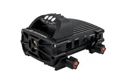
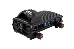
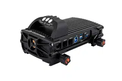
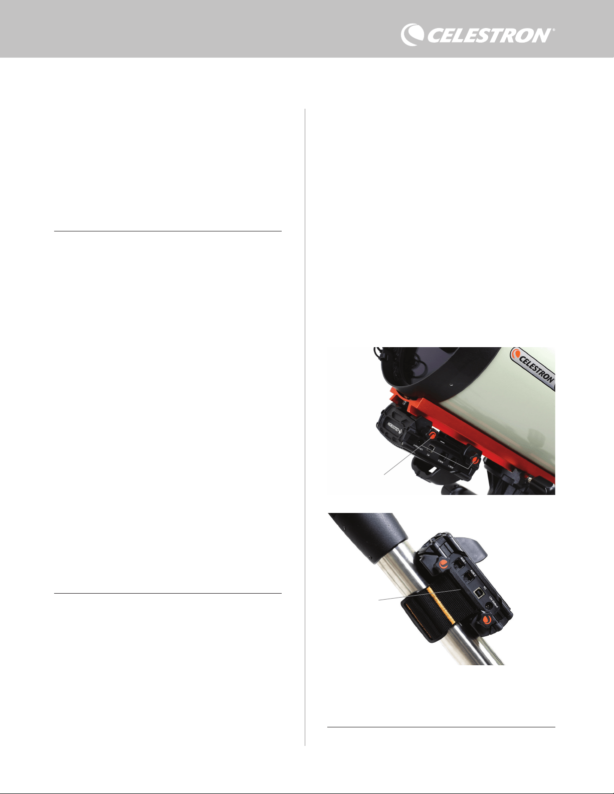
1. Dew heater ports
2. Power input jack
3. Thermistor ports
4. AUX ports
5. PC port
6. Power output port
7. Bridge
1. 2.
3.
4.
5.
6.
Fig 2-1
Fig 2-2
Fig 2-3
2.
3.
1.
6.
7.
5. 4.
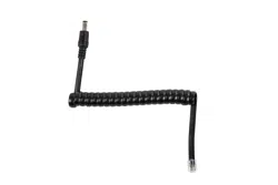
1. Smart DewHeater Controller 2x
2. Power cable
3. Auxilliry cable
4. Mount power cable
5. Tripod leg strap
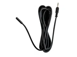
6. Thermistor Cable
2 | ENGLISH
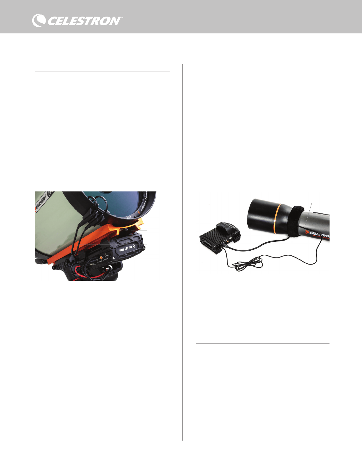
DEW HEATER CONTROL
The Smart DewHeater Controller 2x provides automatic “smart”
control for up to two dew heater rings or dew heater bands/strips.
If you are using the controller with a Celestron Dew Heater Ring,
connect the ring’s power input jack to one of the controller’s dew
heater output ports using the extension cable that comes with the
ring. Next, plug the included thermistor cable into the ring’s thermistor
jack and the corresponding thermistor port on the controller. (Figure
3) The thermistor indicates the Schmidt corrector lens’s temperature.
The controller uses this data along with information from the
controller’s integrated environment sensor (i.e., ambient temperature
and humidity) to provide just the right amount of power to the ring
to prevent dew. If you are using battery power, this system greatly
increases battery life under most conditions. Once you connect the
ring to one of the controller’s dew heater ports, it will begin to heat up
(unless the port has been manually disabled, which will be discussed
later in this manual).
You will need an additional thermistor cable if you wish to use
automatic smart control for more than one Celestron Dew Heater
Ring. The thermistor cable is a standard 2.5mm audio cable, which
you can find at most electronics retailers. Be sure to get one that is
long enough to accommodate your setup.
The controller’s environmental sensor resides in the “bridge” on the
controller’s enclosure (Figure 2). This location protects the sensor
from any heat radiating from the enclosure while still providing good
airflow. An integrated environmental sensor gives you a simpler,
cleaner setup without dangling external sensors to get in your way.
Occasionally, you should recalibrate the environmental sensor.
Recalibrating heats the sensor so that any accumulated moisture
evaporates, ensuring the most accurate temperature and humidity
data and the most efficient power use. We recommend recalibrating
before initial use and after long periods of storage in humid conditions.
The process is easy; we’ll explain it later in this manual.
If you do not wish to use automatic smart control, you can manually set
the power for each of the dew heater ports from 0% (off) to 100% (full
power). We’ll discuss this option in more detail later in the manual.
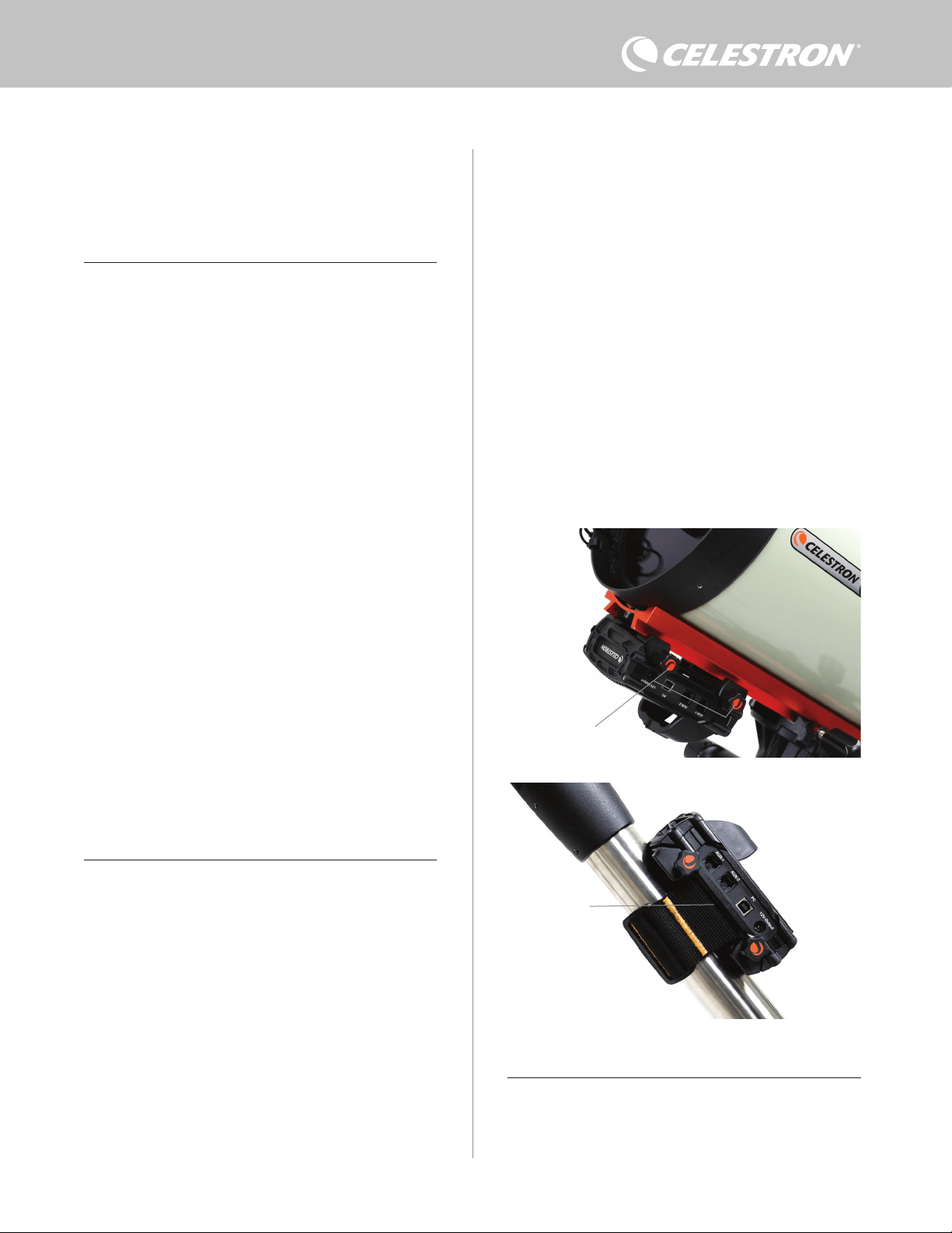
If you are using a non-Celestron heating band or strip, it will need an
RCA-type plug to connect to the controller’s heater output ports. You
have two options for controlling third party bands/strips:
1. You can purchase the optional Thermistor for Celestron Smart
DewHeater Controllers to provide automatic smart power control.
Connect the heating band to the telescope and connect its plug
to one of the dew heater ports. Then, place the tip of the probe
thermistor under the heating band so it is secure (you may want
to use tape). Connect the thermistor’s plug to the corresponding
jack on the controller (Figure 4). The probe thermistor is not as
accurate as the Celestron Dew Heater Ring’s built-in thermistor,
which contacts the corrector lens directly. Still, it allows for
automatic smart control of heating bands/strips.
2. Alternatively, you can manually set the power output for each dew
heater port from 0% to 100%, as mentioned previously.
Each of the dew heater ports can deliver a maximum of 84W power
(7A max current), which should be more than enough for most dew
heaters. If a connected dew heater draws more than 84W, the port
will automatically shut off to protect the circuitry. After reducing the
load, you can re-enable the port, a process that we’ll discuss later in
this manual
POWER CONTROL
A handy feature of the Smart DewHeater Controller 2x is its ability to
provide 12V DC power to an external device. Many users choose to
power their mount this way, enabling them to run their dew heaters
and mount from a single power source.
To power a 12V DC device, use the included mount power cable—
the cable with 12V DC barrel connectors on both ends (Figure 1).
Simply connect the device’s power input to the controller’s 12V DC
power output port. The port requires a 12V DC 5.5mm/2.1mm tip
positive barrel connector. One end of the mount power cable has an
integrated nut on its barrel connector. You can thread this onto the
power jack on Celestron mounts with a threaded barrel connector
for the most secure connection. Power will flow through the port as
soon as you connect the device; there is no need to turn the port on
(unless you disabled the port previously, which we’ll discuss later).
Fig 3
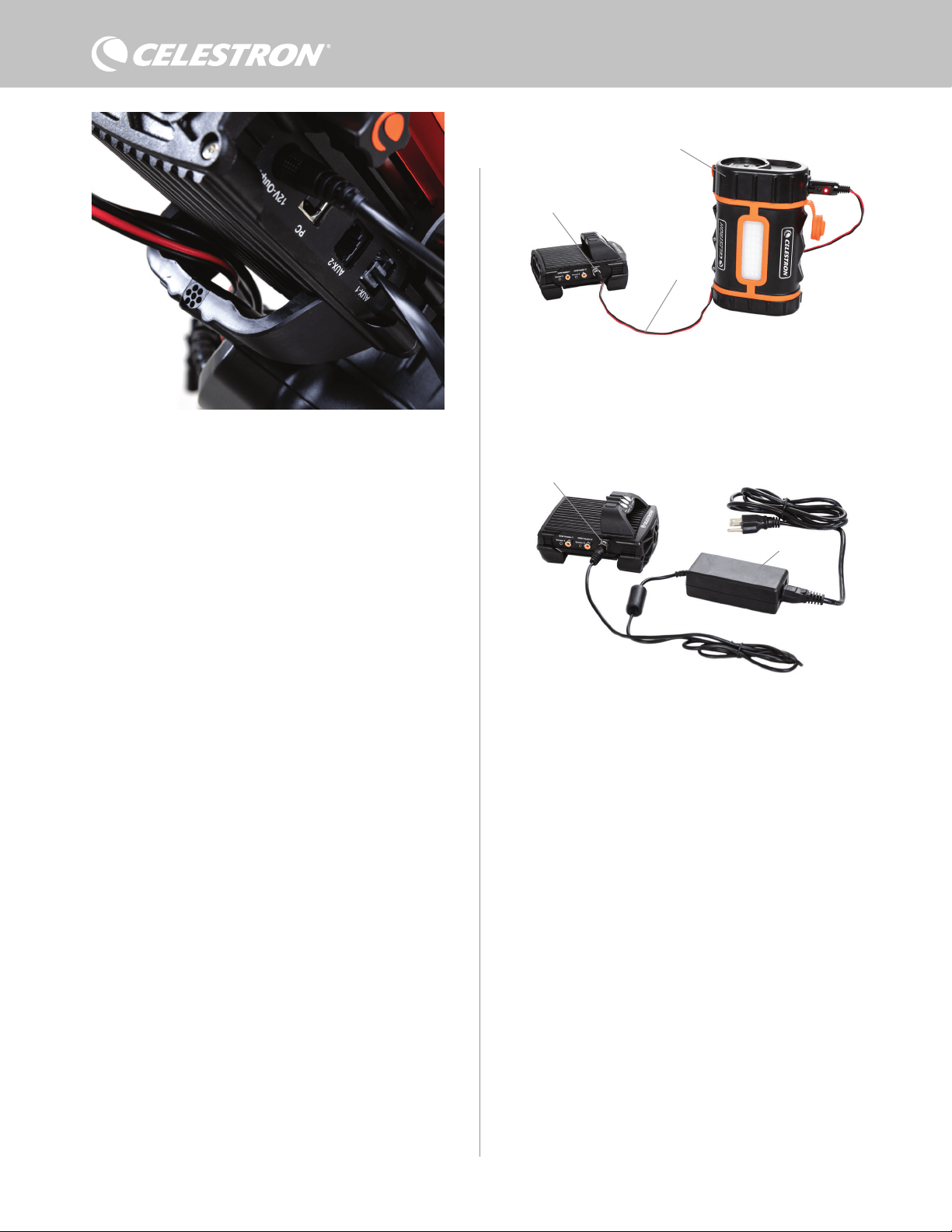
Connect a Celestron Dew Heater Ring to the controller using the extension cable that comes
with the ring and the thermistor cable that comes with the controller.
Fig 4
If you are using a heating band or strip from another manufacturer, you will need the
optional Celestron Thermistor for Smart DewHeater Controllers.
Celestron Thermistor
Extension cable
Thermistor cable
ENGLISH | 3
CG-5/Vixen or CGE/Losmandy dovetail bar. If you have a dovetail
bar on your optical tube, this is perhaps the easiest and most
convenient way to connect the controller to your setup. Simply
loosen the controller’s clamping knobs, place the controller’s
clamps onto the dovetail rail, and then firmly tighten the clamping
knobs (Figure 5).
- Use the included tripod leg strap to attach the controller to one of
your tripod’s legs. Insert the strap through the slots in the bottom of
the controller’s enclosure, wrap the strap around one of the tripod
legs, tighten the strap with the buckle, and secure the strap end to
itself with the hook-and-loop fasteners on the strap (Figure 6).
- If your tripod’s accessory tray is large enough, you can place the
controller on the tray. If you choose this method, keep in mind that
the controller will not be secured in place. Be careful to avoid
forceful cable pulls.
NOTE: DO NOT PLACE THE CONTROLLER ON THE GROUND!
Water and dirt can potentially enter the controller and may cause
electrical problems.
USING THE BRIDGE FOR CABLE MANAGEMENT
The bridge on the enclosure houses the controller’s environmental
sensor, isolating it from radiant heat to provide the most accurate
ambient temperature and humidity data. We also designed the bridge
to help with cable management. You can run cables underneath the
The power port can deliver a maximum of 84W power (7A max
current). If a connected device draws more than 84W, the port will
automatically shut off to protect the circuitry. After reducing the load,
you can re-enable the port, a process that we’ll discuss later.
STATUS LEDS
There are three LEDs on the bridge that indicate the controller’s
status:
- The middle LED indicates whether power is flowing to the controller.
- The LED labeled “Over Current” illuminates if the current draw is
greater than the power source can provide. If this happens, either
disconnect or reduce power to one of the devices connected to the
controller or use a power source capable of delivering more current.
You will need to set the max current draw for your power supply for
this LED to work properly (as discussed later in this manual).
l If one of the ports has experienced a short circuit from a
connected device, the “Over Current” LED will blink, and
the affected port will turn off. You will need to follow the
instructions that appear later in the manual to re-enable the
port and use it again.
- The LED labeled “Under Voltage” will illuminate if the input power
to the controller is less than 11.0V DC. This could happen if your
battery power supply is nearing the end of its charge. In this case,
you would need to use a different power source or recharge the
battery. The under-voltage LED helps protect your battery from
becoming over-drained, which could reduce the battery recharge
lifetime.
l If the input voltage of the power source exceeds 13.8V, all
output ports will turn off to protect the circuitry, and the
“Under Voltage” LED will blink. In this case, you would need
to replace the power source with one that supplies less than
13.8V and manually re-enable all the output ports according
to the instructions that appear later in this manual.
If you are under dark skies and find the LEDs too bright, you can
adjust their brightness. We’ll explain how later in the manual.
ADDITIONAL CIRCUIT PROTECTION
In addition to the status LEDs’ warnings, the Smart DewHeater
Controller 2x features other circuit protection measures to keep your
equipment safe.
If the total power draw of the controller exceeds 120W (10A max
current), the controller will automatically shut off. Reduce the load on
the controller and manually re-enable the ports using the instructions
that appear later in this manual.
If you accidentally connect the input power source with the improper
polarity, the controller will not power on to prevent circuit damage.
3. Mounting the Controller to Your Setup
Decide how you want to attach the controller to your telescope setup.
There are a few options:
- Use the integrated dovetail clamp to connect the controller to a
Fig 6
Tripod strap slot
Fig 5
Clamping knobs
4 | ENGLISH
bridge to keep them captive and organized (Figure 7). Simply insert
the cable end underneath the bridge and pull it through until there is
enough slack to connect the cable’s plug to the corresponding port
on the controller.
4. Powering the Controller
You will need a suitable 12V DC power supply for the Smart
DewHeater Controller 2x. The appropriate 12V DC power supply will
depend on the equipment you have plugged into the controller. The
maximum power the controller can handle is 120W (10A max current
@ 12V DC), but many use cases require less power. When choosing
a power supply, it is crucial to determine the approximate amount of
power needed for your setup and how much battery capacity you’ll
need for your observing session.
Helpful formulas:
- Voltage (in Volts) x Current (in Amps) = Power (in Watts)
- Current (in Amps) x Time (in hours) = Battery current capacity (in
Amp-hours) required
- Power (in Watts) x Time (in hours) = Battery power capacity (in
Watt-hours) required
The maximum input voltage for the power input jack is 13.8V DC.
Make sure your power supply’s output voltage does not exceed this.
If over 13.8V DC is supplied, all output ports will automatically shut
off to protect the circuitry, and the “Over Voltage” status LED on the
enclosure’s bridge will blink.
You will need to choose from the following powering options:
- For portable setups, you’ll need a 12V DC battery. Both the
Celestron PowerTank Lithium Pro and Celestron PowerTank 17AH
will work. Use the included power cable and connect the cigarette-
lighter plug to the battery and the threaded barrel connector to the
controller (Figure 8).
NOTE: If you are using two dew heaters in heavy dew conditions
and also powering a 12V DC device, the controller may be operating
near its 120W power (10A current) limit. In this case, the PowerTank
Lithium Pro and PowerTank 17Ah may not have enough capacity to
run your setup all night. You’ll need a larger capacity battery.
- If you can connect to an AC power outlet, you can use an AC-to-
12V DC adapter. If your setup requires 60W power or less (5A
current or less), you can use Celestron’s AC Adapter-5A. For the
most secure connection, connect the adapter’s output cable to the
controller’s power input jack, thread the connector on the end of
the cable to the exterior of the jack, and then plug the adapter into
an AC power outlet (Figure 9).
WARNING: THE MAXIMUM POWER THE INPUT JACK CAN
ACCEPT IS 120W (10A MAX CURRENT @ 12V). If you connect
a power source capable of delivering more than 120W to the power
input jack, you could damage the controller’s power cable and the
controller itself. If you require more than 120W, we recommend
purchasing the Celestron Smart DewHeater and Power Controller
4x, which can handle up to 240W (20A max current).
NOTE: If operating near 10A max current, there will be a voltage
drop of approximately 1V from the power source to the controller
due to the power cable. In this case, we recommend using a power
source that supplies slightly more than 12V (but less than 13.8V).
Refer to Appendix A for example power supply setups for reference.
Once you have chosen your power supply, you will need to set the
maximum current draw for your power supply using the Celestron hand
control or CPWI (discussed later in this manual). Then, if the controller
Fig 9
If you need 5A (60W) of power or less for your setup, and you have access to an AC power
outlet, you can use the Celestron AC Adapter-5A to power the controller. Use the threaded
barrel connector for the most secure connection.
Threaded barrel connector
AC Adapter-5A
Fig 8
You can use the included power cable to connect a battery to the controller. Use the
threaded barrel connector for the most secure connection.
PowerTank Lithium Pro
Power Cable
Threaded Barrel Connector
The enclosure’s bridge was designed to facilitate cable management.
Fig 7
ENGLISH | 5
draws more current than your specified maximum, the “Over Current”
LED will illuminate. By default, the maximum current draw is 2.0A,
which is relatively low. So, if you have not set the maximum current
draw for your power source, this LED may turn on prematurely.
When you connect power to the power input jack, the controller is on.
Power should flow through the ports.
5. Connecting to a Celestron Mount
If you are using the Smart DewHeater Controller 2x with a Celestron
mount, you can connect it to the mount to change settings and
monitor data with the mount’s hand control. This is an excellent option
for setups without a PC connection.
Before using your telescope’s hand control with the Smart
DewHeater Controller 2x, you may need to update your hand control’s
firmware. For the NexStar+ hand control, you’ll need firmware version
5.33.1333 or greater. For the StarSense hand control, you’ll need
firmware version 1.22.21333 or greater. You can check your firmware
version number by pressing the MENU button and using the SCROLL
and ENTER buttons to navigate to Hand Control>Get Version Info.
Use the Celestron Firmware Manager (CFM) software to update the
firmware if needed. You’ll find the latest version here: https://www.
celestron.com/pages/drivers-and-software
To use the NexStar+ or StarSense hand control, connect the supplied
AUX cable to an AUX port on the Celestron mount and an AUX port
on the Smart DewHeater Controller 2x. Then, plug the mount’s hand
control into the mount as you usually would. Alternatively, you can
connect the hand control directly to one of the controller’s AUX ports.
You can also use the included mount power cable to power your
mount from the power output port (Figure 10).
NOTE: Power does not flow to the AUX ports unless a Celestron
mount is connected to one of the AUX ports and turned on. If you
do not have a Celestron mount connected, a hand control plugged
directly into one of the AUX ports will not receive power.
6. Using the Controller with a Celestron
Hand Control
Once connected, you can change settings and monitor data using the
NexStar+ or StarSense hand control. To do this, turn on the mount,
press the MENU button on the hand control, navigate to the Dew
Heater menu using the SCROLL buttons, and press ENTER. Now,
use the SCROLL buttons to view the Dew Heater menu options, and
press ENTER to select.
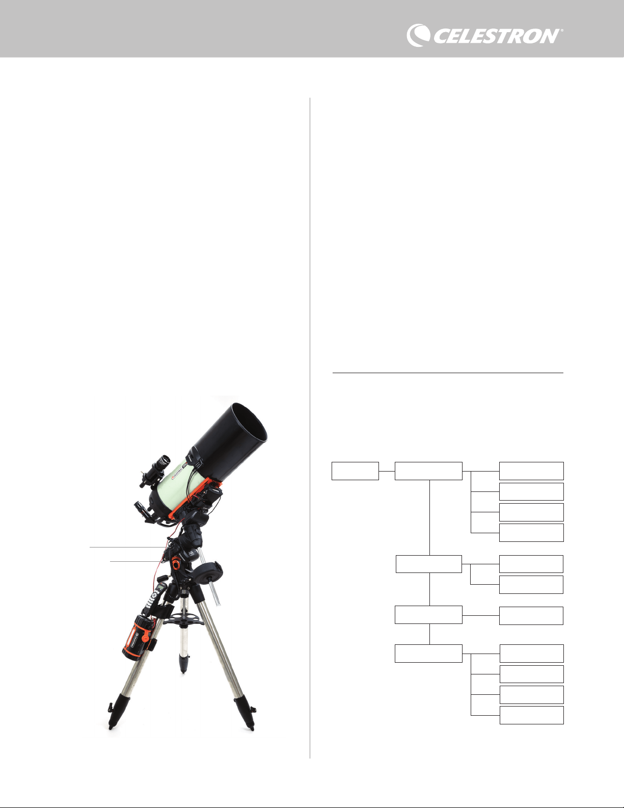
Figure 11 shows the Dew Heater menu tree.
NOTE: If you are using the StarSense hand control, you will need
to use the SCROLL buttons to see the entire text for some menu
selections.
INPUT POWER
Select this to monitor the power draw from the devices connected to
the controller. You can also check the input current from the power
source and set the maximum current draw. Use the SCROLL buttons
on the hand control to choose from the following options, and press
ENTER to select.
Dew Heater Input Power
Power Status
Voltage Status
Current Status
Current Limit
Dew Heater #1
Dew Heater #2
Power #1
Ambient Temp
Humidity
Dew Point
Recalibration
Dew Heater Ports
Power Ports
Environment
Hand control Dew Heater menu tree
Fig 11
Fig 10
The included AUX cable allows the mount to communicate with the controller. You can also
use the included mount power cable to power your mount from the power output port.
AUX cable
Mount power cable

6 | ENGLISH
l Power Status – Displays the power draw from the devices
connected to the controller.
l Voltage Status – Displays the voltage provided by the input
power source.
l Current Status - Displays the current the devices connected to the
controller are using.
l Current Limit – This menu allows you to set the maximum current for
the power source. When the current draw from connected devices
exceeds this amount, the “Over Current” LED on the controller’s
bridge will illuminate. Press ENTER to set the current limit from
1.0A to 10.0A. Press ENTER when done.
NOTE: If you exceed the current limit and the “Over Current” LED
turns on, you need to disconnect a device from the controller or
use another power source that can supply more current. If you use
another power supply, make sure to change the current limit.
DEW HEATER PORTS
This option displays the power draw for each dew heater port. If you
do not wish to use the automatic “smart” control for the dew heaters,
this is where you will manually set the power output for each dew
heater port.
After selecting Dew Heater Ports from the menu, you can scroll to the
two heater ports. For each heater port, the LCD on the hand control
will display whether the port is in Manual or Auto mode and the power
draw on the port at that moment.
To change from Auto mode to Manual mode, select the port using
the SCROLL buttons, then press ENTER. Then use the SCROLL
buttons to choose between Manual Mode and Automatic mode, and
press ENTER.
- If you select Manual Mode, you will need to specify a desired Power
Level. This is a number between 0 and 100—the percentage of
maximum power to the dew heater connected to the port. Once
you have entered your desired value, press ENTER. To turn a dew
heater port off, select the dew heater port, change to Manual Mode,
and set the Power Level to 0%.
- If you select Automatic Mode, you will need to set the aggression
level. This is a number from 1 (lowest aggression) to 10 (highest
aggression) that indicates how active the smart dew controller is
when preventing dew. A higher aggression setting will use more
power but will provide the highest level of dew prevention during
changing environmental conditions. In general, you can use a
lower aggression setting for warmer and drier observing sites and
a higher setting for cooler and more humid observing sites. Also,
use a higher aggression setting for larger apertures and lower
aggression if you are using a dew shield or it is windy. If you are
unsure of which aggression setting to use, try 5 (the default setting)
initially. After you have set the aggression, press ENTER.
POWER PORT
This selection allows you to monitor the 12V DC power output to a
device connected to the power port.
If a device is connected to the port and you select “Power Port” from
the Dew Heater menu, the LCD will display the power draw. To disable
power to the port to turn off a connected device, press ENTER for the
selected port. The LCD screen will then display “Disable port?” To
proceed, press ENTER. If you do not want to disable power, press
BACK. To re-enable power to the port and turn a connected device
back on, press ENTER again.
ENVIRONMENT
This selection allows you to view the data from the environmental
sensor. This is also where you can recalibrate the sensor for optimal
performance. Use the SCROLL buttons on the hand control to
choose from the following options and press ENTER to select.
l Ambient Temperature – Displays the ambient air temperature.
l Humidity – Displays the relative humidity.
l Dew point – This value is calculated in real-time using ambient
temperature and humidity data. If the lens’s temperature drops
below the number displayed, dew will form on its surface.
l Recalibration – To begin recalibration of the environmental sensor,
select this option and press ENTER. The sensor will heat up to
evaporate any moisture accumulated on it, providing the most
accurate sensor readings. Recalibration takes about 10 minutes
from when you press ENTER to when the sensor has cooled
back to ambient temperature. We recommend recalibrating the
environmental sensor periodically, especially if the sensor has not
been used in a while or has been stored in humid conditions.
n If you check the ambient temperature or humidity during
recalibration, the display will report the values last detected
before recalibration began.
REENABLING A DISABLED PORT
As discussed previously, the controller’s ports automatically shut off if
one of the ports draws more than 84A (7A max current) or if the total
load on the controller exceeds 120W (10A max current). To re-enable
a port after it has been automatically disabled:
l First, reduce the load on the controller.
l To select the disabled port, press MENU, scroll to “Dew Heater,”
and press ENTER. Then scroll to “Dew Heater Port” or “Power
Port,” and press ENTER.
l The LCD screen will display “Reset Fuse?” Press ENTER to re-
enable the port.
NOTE: If the total load on the controller exceeds 120W (10A max
current), you will need to re-enable all the ports.
7. Connecting to a PC
It may be most convenient for some setups to connect the Smart
DewHeater Controller 2x to a PC to adjust settings and monitor data.
This is especially true if you are already using a PC to control your
mount or any imaging cameras or guiding cameras.
To use a wired connection, you will need a USB Type A-to-Type B
cable (not supplied). Plug into the PC port on the controller and
a USB port on your PC. Once you power the controller on, the
computer should recognize it.
If using a Celestron computerized mount, you can connect to the
mount and control it through the Smart DewHeater Controller using
the free CPWI PC software. To do this, use the included AUX cable
to connect one of the controller’s AUX ports to one of the mount’s
AUX ports.
ENGLISH | 7
8. Using the Controller with CPWI
Software
If you are already controlling your telescope or camera from
a computer, you will love controlling the Smart DewHeater
Controller 2x with our free Celestron CPWI software. To
download the latest version, visit: https://www.celestron.com/
pages/celestron-pwi-telescope-control-software
Install the software and open CPWI. Select “Start” if the
opening window appears. Then, click on the “Connection” icon
in the upper-left corner of the screen. If you are using a wired
connection, select “Mount USB.” If you are using the SkyPortal
WiFi Module, click on the “Connection” icon and then select
“WiFi.”
CPWI should find and connect to the controller. Once connected,
the Dew Heater icon will appear in the selection menu on the left
side of the screen.
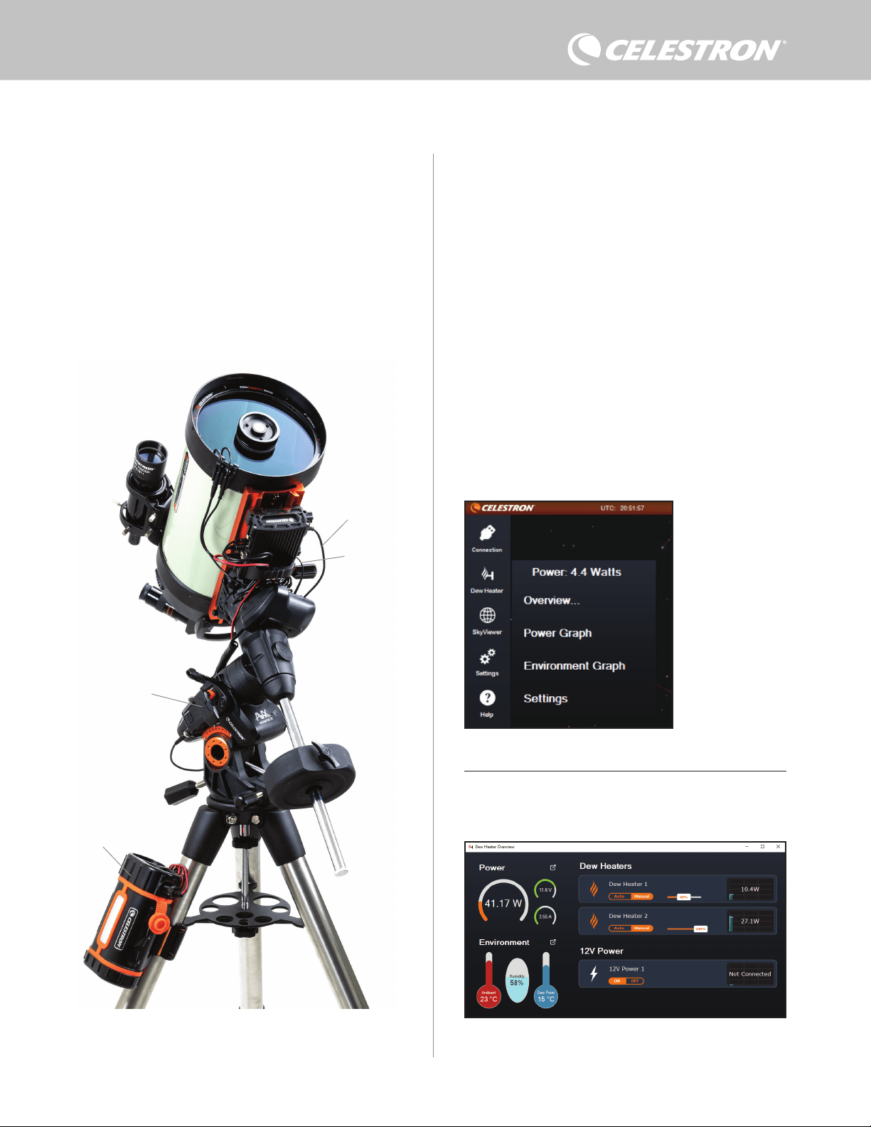
Selecting the Dew Heater icon will display the Dew Heater menu.
(Figure 13). The first line in the Dew Heater menu indicates the
total power draw for any devices connected to the controller. To
see more data, click Overview.
OVERVIEW
The Overview screen displays the power draw for each port on the
controller (Figure 14). The icons beside any ports currently in use
will turn orange with the power draw over time in the small graph
To connect a PC to the controller wirelessly using the optional
SkyPortal WiFi Module, you will need a Celestron mount and the
WiFi module accessory (sold separately). Plug the WiFi module into
an AUX port on the mount. Connect another AUX port on the mount
to one of the AUX ports on the controller using the supplied AUX
cable. You can also use the included mount power cable to power
your mount from one of the power output ports (Figure 12). Once all
the cables are connected, turn on the mount.
NOTE: If your mount only has one AUX port, you’ll need to purchase
the optional AUX Port Splitter. This converts the mount’s single AUX
port into two AUX ports.
Fig 13
CPWI Dew Heater menu
Fig 14
Overview screen
Fig 12
If you are using a Celestron mount with the SkyPortal WiFi Module, you can connect to the
controller via WiFi through the mount using the supplied AUX cable. You can also use the
included mount power cable to power your mount from the power output port.
Mount Power Cable
SkyPortal WiFi Module
PowerTank Lithium Pro
AUX Cable
8 | ENGLISH
to the right. In the upper-left corner of the Overview screen, you
can see the total power and current draw from the controller and
the input voltage from the power source. Below that, you can see
the ambient temperature and humidity data from the environmental
sensor and the calculated dew point.
The Overview menu is also where you can turn each output port on or
off, including both dew heater ports and the output power port. If you
are remotely logging into the PC connected to the controller, you can
remotely turn your devices on and off here. For the power port, simply
use the ON/OFF button. For the dew heater ports, select “Manual”
and set the power level to zero.
As discussed previously, the controller will automatically shut off its
ports if there is too much load on one of the ports (greater than 84W)
or if the total load on the controller exceeds 120W (10A max current).
If this happens, the Fuse Blown Notification will appear, and you will
see a “RESET FUSE” box next to the affected port(s) in the Overview
screen (Figure 15). To re-enable a port after it has been automatically
disabled, first reduce the load on the port as needed. Then, click on
the “RESET FUSE” box to re-enable power to the port.
slider to set the aggression. If you are unsure of what aggression
setting to use, try 5 (the default setting) initially.
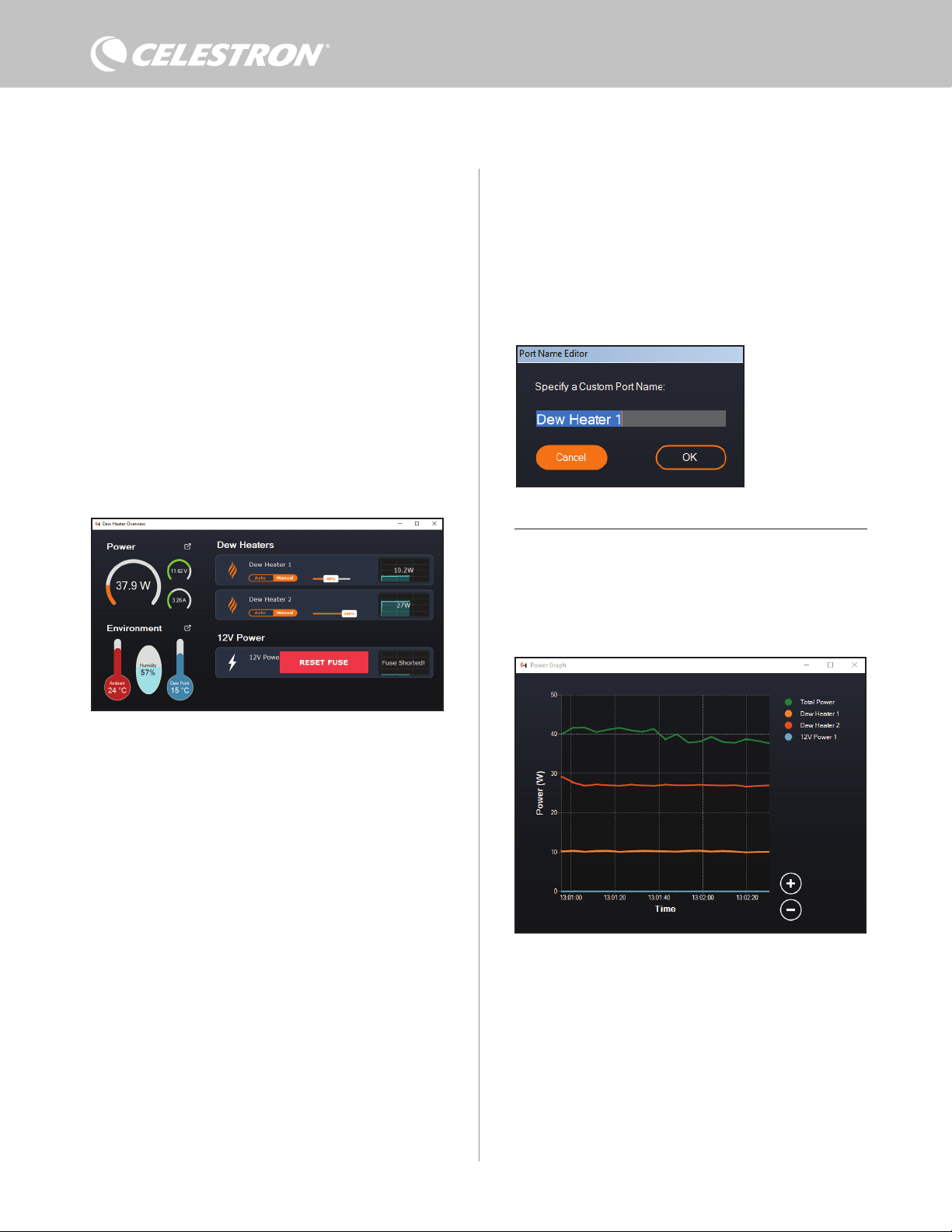
You can rename each port in the Overview screen by clicking on the
name of the port. The Port Name Editor window will appear (Figure
16), and you can enter the new name. Click the OK button when
done, and the new name will appear for the port. This will help you
keep your controls organized, as you can rename each port for the
connected device. For example, you can rename your ports “8-inch
Dew Heater Ring” or “CGX Mount.”
POWER GRAPH
Select “Power Graph” from the Dew Heater menu to bring up the
Power Graph window (Figure 17). You can also access the Power
Graph directly from the Overview screen by clicking on the shortcut
arrow icon next to the word “Power” on the upper-left side of the
Overview screen.
The Power Graph shows power usage over time for all devices
connected to the controller’s dew heater ports and output power port.
Each color line on the graph represents a different port. If you wish to
change the color for a port, mouse over the port and right-click.
You can hide a port from the graph by clicking on the circle to the left
of the port’s name. To re-enable its line on the graph, simply click on
the circle again.
To “zoom in” to a specific time range on the graph to see more detail,
use the “+” and “-” circles at the bottom right of the graph. You can
Fig 17
Power Graph window
Fig 15
If the power draw on a port exceeds 84W, the port will automatically shut off. To re-enable,
reduce the load on the affected port and then click the RESET FUSE box.
Fig 16
Port Name Editor window
NOTE: If the total load on the controller exceeds 120W (10A max
current), you will need to re-enable all ports.
Under each Dew Heater port, you’ll find buttons to change from Auto
“smart” control mode to Manual control mode:
- If you select Manual Mode, you will need to indicate the desired
power level. This is a number between 0 and 100—the percentage
of maximum power to the dew heater connected to the port. Once
you have entered your desired value, press ENTER.
l To turn a dew heater port off, select Manual control and set the
slider to 0%.
- If you select Automatic Mode, you will need to set the “aggression”
level. This is a number from 1 (lowest aggression) to 10 (highest
aggression) that indicates how active the controller is when
preventing dew. A higher aggression setting will use more
power but will provide the highest level of dew prevention during
changing environmental conditions. In general, you can use a
lower aggression setting for warmer and drier observing sites and
a higher setting for cooler and more humid observing sites. Also,
use a higher aggression setting for larger apertures and lower
aggression if you are using a dew shield or it is windy. Use the
ENGLISH | 9
To “zoom in” to a specific time range on the graph to see more detail,
use the “+” and “-” circles at the bottom right of the graph. You can
also use “pinch to zoom” if you have a touchpad or use your mouse’s
scroll wheel to zoom in and out of time ranges. Use the slider that
appears at the bottom of the graph to find a particular time range.
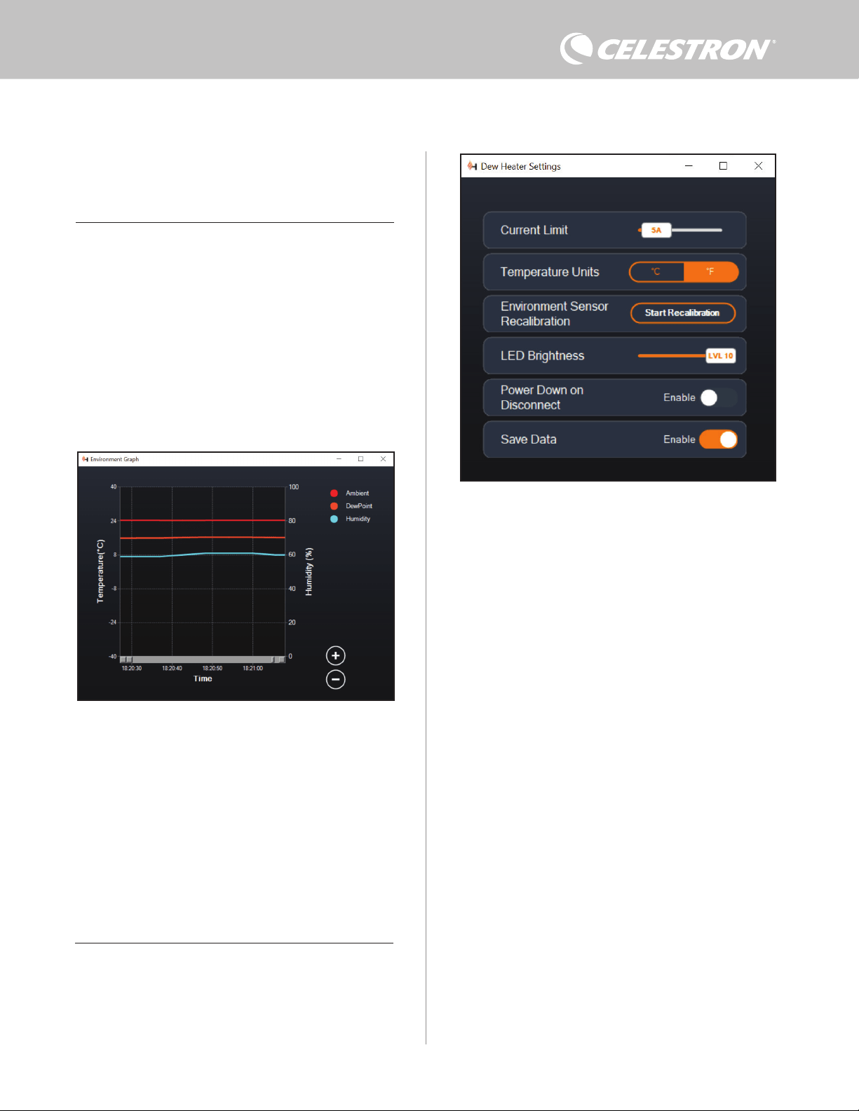
To change temperature units from degrees Fahrenheit (default)
to degrees Celsius, use the “Settings” selection from the Dew
Heater menu.
SETTINGS
The “Settings” selection from the Dew Heater menu brings up the
Dew Heater Settings window (Figure 19).
- Current Limit
l Use the slider to set the maximum current for the power supply
you are using. If the power draw from the controller exceeds
Fig 18
Environment Graph window
Fig 19
Dew Heater Settings window
also “pinch to zoom” if you have a touchpad or use your mouse’s
scroll wheel to zoom in and out. Use the slider that appears at the
bottom of the graph to find a particular time range.
ENVIRONMENT GRAPH
Select “Environment Graph” from the Dew Heater menu to bring up
the Environment Graph window (Figure 18). You can also access the
Environment Graph directly from the Overview screen by clicking
on the shortcut arrow icon next to the word “Environment” on the
left side of the Overview screen. This graph shows the ambient air
temperature, humidity, and calculated dew point over time. The air
temperature and dew point use the °C temperature scale on the left
of the graph. Humidity uses the % humidity scale on the right of the
graph. Each color line on the graph represents a different value. If
you wish to change the color for a value, mouse over it and right-click.
You can hide a value from the graph by clicking on the circle to the left
of the value’s name on the graph. To re-enable its line on the graph,
simply click on the circle again.
the set max current, the “Over Current” LED on the controller
enclosure’s bridge will light up. If this occurs, you will need to
reduce the power draw by turning down or turning off devices
connected to the controller. Alternatively, you can use another
power supply capable of providing more current. If you do this,
make sure to adjust the current limit accordingly.
- Temperature Units
l Change the units of temperature in CPWI using the °C and
°F buttons.
- Environment Sensor Recalibration
l Use the “Start Recalibration” button to recalibrate the
environmental sensor. This heats the sensor to evaporate any
moisture that has accumulated on it. Recalibration helps provide
the most accurate sensor readings. It takes about 10 minutes
for the sensor to heat up and cool back down. We recommend
recalibrating the environmental sensor periodically, especially if
the sensor has not been used in a while or has been stored in
humid conditions. This will help provide the most efficient power
usage for the dew heaters.
n If you check the ambient temperature or humidity during
recalibration, the display will report the values last
detected before recalibration began.
- LED Brightness
l Set the brightness of the LEDs on the controller using the
slider. One is the dimmest setting, and ten is the brightest.
- Power Down on Disconnect
l You can choose to power off all connected devices when you
disconnect the controller from CPWI. To do this, click the Enable
button. When you reconnect CPWI, all ports will turn back on.
10 | ENGLISH
If you do not enable this feature, power will flow through the
controller as usual when you disconnect from CPWI.
- Save Data
l This feature allows you to export the raw data from the controller in
a .CSV format, which you can open in Microsoft Excel or Google
Sheets. If you select this option, you can find the saved .CSV file
in this folder on your PC: Documents\Celestron\CPWI
To disconnect from the Smart DewHeater Controller 2x at the
end of an observing session, you can either close CPWI and the
Application Shutdown window will appear (Figure 20), or you can
select the “Connection” icon in the upper left corner and select
“Disconnect.” If you have selected “Power Down on Disconnect”
from the Dew Heater>Settings menu, all devices connected to the
controller will turn off. Otherwise, power will continue to flow through
the controller’s ports as usual.
9. Specifications
Weight: 1.2 lbs.
Dimensions: 5.5” x 4.5” x 3.25”
Enclosure: Aluminum, fan-cooled, integrated dovetail clamps and
tripod strap
Power Input: 12V DC nominal, 13.8V DC max input voltage,
10A max input current, 5.5mm/2.1mm tip positive threaded
barrel connector
Power Output Port: 12V DC, 5.5mm/2.1mm tip positive barrel
connector, 7A max output current
Dew Heater Outputs: 2x RCA jacks, 12V DC, 7A max output
current for each port
Thermistor Jack: 2x 2.5mm Audio jack, compatible with Celestron
Dew Heater Rings and optional Celestron Thermistor
AUX Ports: 2x AUX ports, compatible with Celestron mounts and
other Celestron products
Environmental Sensor: Integrated, gives ambient temperature and
humidity data, can be recalibrated for best performance
Circuit protection: internally resettable fuses for each port,
reverse polarity protection, under-voltage, over-voltage, under-
current, over-current
Firmware: Upgradeable thorough Celestron Firmware Manager
(CFM) software
Power cable: 5.5mm/2.1mm threaded tip positive barrel connector
plug on one end, cigarette-lighter plug on the other end, 10A fuse,
16 gauge wire
Fig 20
Application Shutdown window
ENGLISH | 11
Appendix A: Determining Power Supply
Requirement Examples
EXAMPLE SETUP #1
- Celestron 8” Dew Heater Ring connected to dew heater port #1
l Max current draw of 8” Dew Heater Ring = 1.7A
l Max power required for 8” Dew Heater Ring = 12V x 1.7A = 20.4W
- Celestron Advanced VX EQ mount connected to power port #2
l Max current draw for Advanced VX EQ mount when slewing at
highest speed = approximately 2.0A
l Max power required for Advanced VX when slewing at max
speed = 12V x 2.0A = 24.0W
In this example, the total max power required by the controller would
be about 48W.
- If you have access to AC power, the Celestron AC Adapter-5A,
which can handle up to 60W, would be a good choice for powering
the controller.
- For portable setups, the Celestron PowerTank Lithium Pro can
provide up to 120W power (10A max current), so it would work well
with this example setup.
l The battery capacity of the PowerTank Lithium Pro is 158.7 Watt-
hours. The controller uses approximately 48 watts power per
hour. Therefore, the battery will last over 3 hours in this example.
Suppose you are using auto smart control for the dew heater
ring. In that case, you can expect the battery to last significantly
longer since the ring will probably not operate continuously
at max power. Similarly, if you are not repeatedly slewing the
telescope at its highest speed, then the power consumed by the
mount will be much less, further extending battery charge life.
EXAMPLE SETUP #2
- Celestron 11” Dew Heater Ring connected to dew heater port #1
l Max current draw of 11” Dew Heater Ring = 2.5A
l Max power required for 11” Dew Heater Ring = 12V x 2.5A
= 30.0W
- Other manufacturer’s heating band/strip for guidescope connected
to dew heater port #2
l Max current draw for heating band/strip for guidescope =
approximately 1.0A
l Max power required for heating band/strip for guidescope = 12V
x 1.0A = 12.0W
- Celestron CGX EQ mount connected to power port #2
l Max current draw for CGX EQ mount when slewing at highest
speed = approximately 3.0A
l Max power required for CGX EQ mount when slewing at max
speed = 12V x 3.0A = 36.0W
In this example, the total max power required by the controller would
be about 78W.
- If you have access to AC power, a high-power AC-to-DC power
supply will work well for powering the controller. Celestron’s AC
Adapter-5A would not work since its maximum is 60W.
l If the AC-to-DC power supply voltage is variable, make sure to set
it to 12V before connecting it to the controller. Also, remember
that the power input jack is tip positive.
- For portable setups, the Celestron PowerTank Lithium Pro can
provide up to 120W power (10A max current), so it would work with
this example setup. However, it may not have enough power storage
capacity for your entire observing session.
l The battery capacity of the PowerTank Lithium Pro is 158.7
Watt-hours. The controller will use approximately 78 watts
power per hour. Therefore, the battery should last about 2
hours in this example. Suppose you are using auto smart
control for the dew heater ring. In that case, you can expect the
battery to last significantly longer since the ring will probably
not operate continuously at max power. Similarly, if you are not
repeatedly slewing the telescope at its highest speed, then
the power consumed by the mount will be much less, further
extending battery charge life.
- For portable setups that you plan to run all night, we recommend
a 12V DC “marine battery” or other portable 12V DC battery with
high power storage capacity.
l If you plan to image all night (8 hours) with this setup, you would
need a marine battery with a capacity of 78W x 8 hours = 624
Watt-hours (i.e., approximately 52 amp-hours @ 12V DC).
12 | ENGLISH
FCC NOTE: This equipment has been tested and found to comply with the limits for a Class B digital device, pursuant to
part 15 of the FCC Rules. These limits are designed to provide reasonable protection against harmful interference in a
residential installation. This equipment generates, uses, and can radiate radio frequency energy and, if not installed and
used in accordance with the instructions, may cause harmful interference to radio communications. However, there is no
guarantee that interference will not occur in a particular installation. If this equipment does cause harmful interference
to radio or television reception, which can be determined by turning the equipment off and on, the user is encouraged to
try to correct the interference by one or more of the following measures:
• Reorient or relocate the receiving antenna.
• Increase the separation between the equipment and receiver.
• Connect the equipment into an outlet on a circuit different from that to which the receiver is connected.
• Consult the dealer or an experienced radio/TV technician for help.
This device complies with part 15 of the FCC Rules. Operation is subject to the following two conditions: (1) This device
may not cause harmful interference, and (2) this device must accept any interference received, including interference
that may cause undesired operation.
Please note that changes or modifications not expressly approved by the party responsible for compliance could void the
user’s authority to operate the equipment.
Product design and specifications are subject to change without prior notification.
This product is designed and intended for use by those 14 years of age and older.
Made in China
© 2022 Celestron • Celestron and Symbol are trademarks of Celestron, LLC. All rights
reserved. Celestron.com • 2835 Columbia Street, Torrance, CA 90503 USA
celestron.com/pages/technical-support
10-22
celestron.com/pages/war ranty

FRANÇAIS | 1
Félicitations pour l’achat du Contrôleur intelligent double de
chauffage anti-buée de Celestron. Ce contrôleur délivre le courant de
manière « intelligente » vers jusque deux systèmes de chauffage anti-
buée ainsi qu’un autre appareil CC 12 V – et met également à votre
disposition un système de gestion des câbles pour votre système.
Lorsque vous branchez vos chauffages anti-buée au contrôleur, un
câble connecte le tout à votre source d’alimentation, tandis qu’un
autre se connecte à votre PC, si désiré.
Si vous préférez ne pas le connecter à un PC, branchez simplement
vos chauffages anti-buée au contrôleurs, sans plus. Le contrôleur
surveillera automatiquement la température ambiante et l’humidité
à l’aide de sont capteur environnemental intégré. Le port de la
thermistance surveille la température de la lentille et délivre la
puissance exactement nécessaire pour empêcher la formation de
buée. Si vous alimentez l’appareil par pile, le système « intelligent »
réduit significativement la consommation énergétique du chauffage,
augmentant d’autant l’autonomie de la pile. Si vous souhaitez
manuellement ajuster les réglages ou surveiller les données,
connectez-le à un PC ou à la commande de votre monture Celestron.
1. Liste des pièces
2. Présentation du contrôleur
SOMMAIRE
Fig 1 – Tous les éléments inclus
Consultez la Figure 2 pour voir la présentation générale des prises
jacks d’entrée, des ports d’entrée et des fonctionnalités du contrôleur
intelligent double de chauffage anti-buée.
Si une pièce présente dans cette liste est manquante, veuillez
contacter l’assistance technique de Celestron à www.celestron.
com/pages/technical-support pour obtenir de l’aide.
1. Liste des pièces . . . . . . . . . . . . . . . . . . . . . . . . . . . . . . . . . . . . . . Pg.1
2. Présentation du contrôleur . . . . . . . . . . . . . . . . . . . . . . . . . . . . . Pg.1
3. Monter le contrôleur à votre système . . . . . . . . . . . . . . . . . . . . . . Pg.3
4. Alimenter le contrôleur . . . . . . . . . . . . . . . . . . . . . . . . . . . . . . . . Pg.4
5. Connexion à une monture Celestron . . . . . . . . . . . . . . . . . . . . . . Pg.5
6. Utilisation du contrôleur avec une commande Celestron . . . . Pg.5
7. Connexion à un PC. . . . . . . . . . . . . . . . . . . . . . . . . . . . . . . . . . . . Pg.6
8. Utiliser le contrôleur avec le logiciel CPWI . . . . . . . . . . . . . . . . Pg.7
9. Spécifications . . . . . . . . . . . . . . . . . . . . . . . . . . . . . . . . . . . . . . . Pg.10
Annexe A:
Exemples de calculs d’exigences d’alimentation . . . . . . . . . . . . Pg.11
CONTRÔLEUR INTELLIGENT DOUBLE DE CHAUFFAGE ANTI-BUÉE
MODE D'EMPLOI
Modèle #94035
FRANÇAIS
1. Ports du chauffage anti-buée
2. Jack d’alimentation
3. Ports de la thermistance
4. Ports AUX
5. Ports PC
6. Port de sortie d’alimentation
7. Passerelle
1. 2.
3.
4.
5.
6.
Fig 2-1
Fig 2-2
Fig 2-3
2.
3.
1.
6.
7.
5. 4.
1. Contrôleur intelligent double de chauffage
anti-buée
2. Câble d’alimentation
3. Câble auxiliaire
4. Câble d’alimentation de la monture
5. Sangle de pied de trépied
6. Câble de la thermistance

2 | FRANÇAIS
CONTRÔLE DU CHAUFFAGE ANTI-BUÉE
Le contrôleur intelligent double de chauffage anti-buée peut contrôler
« intelligemment » jusque deux anneaux de chauffage anti-buée ou
bandes/lanières.
Si vous utilisez le contrôleur avec un anneau de chauffage anti-buée,
connectez le jack d’entrée de l’anneau à l’un des ports de sortie du
contrôleur à l’aide du câble d’extension accompagnant l’anneau.
Ensuite, branchez le câble de la thermistance inclus au jack de la
thermistance de l’anneau et au port de thermistance correspondant
sur le contrôleur. (Figure 3) La thermistance indique la température
de la lentille du correcteur Shmidt. Le contrôleur utilise ces données,
avec les informations relayées par le capteur environnemental intégré
au contrôleur (par ex. mesurant la température ambiante et l’humidité)
pour fournir la quantité d’énergie exactement nécessaire à l’anneau
pour empêcher la formation de buée. Si vous utilisez l’alimentation sur
pile, ce système préserve grandement son autonomie sous la majorité
des conditions. Dès que vous connectez l’anneau à l’un des ports de
chauffage anti-buée du contrôleur, il commence à chauffer (à moins
que ledit port ait été manuellement désactivé, ce qui sera expliqué
plus loin dans ce mode d’emploi).
Vous aurez besoin d’un câble de thermistance supplémentaire
si vous souhaitez utiliser le contrôle intelligent automatique avec
plus qu’un anneau de chauffage anti-buée de Celestron. Le câble
de la thermistance est un câble audio de 2,5 mm standard, que
vous pouvez acheter dans la majorité des revendeurs de matériel
électronique. Assurez-vous d’en acheter un qui soit suffisament long
pour votre installation.
Le capteur environnemental du contrôleur réside dans la « passerelle
» sur le boîtier du contrôleur (Figure 2). Cet emplacement protège
le capteur de toute chaleur émise par le boîtier tout en assurant une
bonne circulation de l'air. Un capteur environnemental intégré vous
offre une configuration plus simple et mieux organisée sans que des
capteurs externes ne vous gênent.
De temps à autres, vous devez recalibrer le capteur environnemental.
Le recalibrage chauffe le capteur de sorte que toute humidité
accumulée s'évapore, garantissant les données de température et
d'humidité les plus précises et l'utilisation de l'énergie la plus efficace
possible. Nous vous recommandons de recalibrer avant la première
utilisation et après de longues périodes de stockage dans des
conditions humides. Le processus est facile; nous l'expliquerons plus
loin dans ce mode d’emploi.
Si vous ne souhaitez pas utiliser le contrôle intelligent automatique,
vous pouvez régler manuellement la puissance de chacun des ports
du chauffage anti-buée de 0% (arrêt) à 100% (pleine puissance).
Nous discuterons de cette option plus en détail plus loin dans le
mode d’emploi.
Si vous utilisez une bande ou une languette chauffante de marque
autre que Celestron, elle aura besoin d'une prise de type RCA pour
se connecter aux ports de sortie de chauffage du contrôleur. Vous
disposez de deux options pour contrôler les bandes/languettes
tierce partie :
1. Vous pouvez acheter la thermistance en option pour les contrôleurs
de chauffage intelligent anti-buée de Celestron pour fournir un
contrôle intelligent automatique de l'alimentation. Connectez la
bande chauffante au télescope et connectez sa fiche à l'un des
ports du chauffage anti-buée. Ensuite, placez la pointe de la
thermistance sous la bande chauffante afin qu'elle soit sécurisée
(vous pouvez utiliser du ruban adhésif). Connectez la fiche de la
thermistance à la prise correspondante sur le contrôleur (Figure
4). La thermistance n'est pas aussi précise que la thermistance
intégrée de l’anneau de chauffage anti-buée de Celestron,
qui entre directement en contact avec la lentille du correcteur.
Néanmoins, cela permet un contrôle intelligent automatique des
bandes/languettes chauffantes.
2. Alternativement, vous pouvez régler manuellement la puissance de
sortie pour chaque port du chauffage anti-buée de 0% à 100%,
comme mentionné précédemment.
Chacun des ports du chauffage anti-buée peut fournir une puissance
maximale de 84W (courant maximal de 7A), ce qui devrait être
plus que suffisant pour la plupart des chauffages anti-buée. Si un
chauffage anti-buée connecté consomme plus de 84W, le port se
coupera automatiquement pour protéger les circuits. Après avoir
réduit la charge, vous pouvez réactiver le port, un processus que
nous aborderons plus loin dans ce mode d’emploi
CONTRÔLE DE PUISSANCE
Une caractéristique pratique du contrôleur intelligent double de
chauffage anti-buée est sa capacité à fournir une alimentation 12V
CC à un appareil externe. De nombreux utilisateurs choisissent
d'alimenter leur monture de cette façon, ce qui leur permet de faire
fonctionner leurs chauffages anti-buée et de les monter à partir d'une
seule source d'alimentation.
Pour alimenter un appareil 12V CC, utilisez le câble d'alimentation
de la monture fourni — le câble avec des barillets de connexion
cylindriques 12V CC à chaque extrémité (Figure 1). Connectez
simplement l'entrée d'alimentation de l'appareil au port de sortie
d'alimentation 12V CC du contrôleur. Le port nécessite un
connecteur à barillet à pointe positive de 5,5 mm/2,1mm 12V CC.
Une extrémité du câble d'alimentation de la monture a un écrou
Fig 3
Connectez un anneau de chauffage anti-buée Celestron au contrôleur à l'aide du câble
d'extension fourni avec l'anneau et du câble de thermistance fourni avec le contrôleur.
Fig 4
Si vous utilisez une bande ou une languette chauffante d'un autre fabricant, vous aurez
besoin de la thermistance Celestron en option pour les contrôleurs de chauffage anti-buée
intelligents.
Thermistance Celestron
Câble
d’extension
Câble de la
thermistance
FRANÇAIS | 3
configuration de votre télescope. Vous avez plusieurs options :
- Utilisez la pince en queue d'aronde intégrée pour connecter le
contrôleur à une barre en queue d'aronde CG-5/Vixen ou CGE/
Losmandy. Si vous avez une monture à barre en queue d'aronde sur
votre tube optique, c'est peut-être le moyen le plus simple et le plus
pratique de connecter le contrôleur à votre configuration. Desserrez
simplement les boutons de serrage du contrôleur, placez les pinces
du contrôleur sur le rail en queue d'aronde, puis serrez fermement
les boutons de serrage (Figure 5).
- Utilisez la sangle de jambe de trépied incluse pour attacher le
contrôleur à l'une des jambes de votre trépied. Insérez la sangle
dans les fentes au bas du boîtier du contrôleur, enroulez la sangle
autour d'un des pieds du trépied, serrez la sangle avec la boucle et
fixez l'extrémité de la sangle à elle-même avec les attaches auto-
accrochantes sur la sangle (Figure 6).
- Si le plateau à accessoires de votre trépied est suffisamment grand,
vous pouvez placer le contrôleur sur le plateau. Si vous choisissez
cette méthode, gardez à l'esprit que le contrôleur ne sera pas fixé en
place. Évitez les tractions brusques sur les câbles.
REMARQUE: NE POSEZ PAS LE CONTRÔLEUR AU SOL! L'eau
et la saleté peuvent potentiellement pénétrer dans le contrôleur et
causer des problèmes électriques.
UTILISATION DE LA PASSERELLE POUR LA GESTION DES
CÂBLES
La passerelle sur le boîtier abrite le capteur environnemental du
intégré sur son connecteur à barillet. Vous pouvez le visser sur la
prise d'alimentation des montures Celestron avec un connecteur
fileté pour la connexion la plus sûre. Le port sera alimenté dès que
vous connecterez l'appareil; il n'est pas nécessaire d'activer le port
(sauf si vous avez désactivé le port précédemment, ce dont nous
parlerons plus tard).
Le port d'alimentation peut fournir une puissance maximale de 84W
(courant max 7A). Si un chauffage anti-buée connecté consomme
plus de 84W, le port se coupera automatiquement pour protéger les
circuits. Si un appareil connecté consomme plus de 84W , le port se
coupera automatiquement pour protéger les circuits.
LED D'ÉTAT
Trois LED sont présentes sur la passerelle qui indiquent l'état du
contrôleur :
- La LED du milieu indique si l'alimentation circule vers le contrôleur.
- La LED étiquetée « Over Current » s'allume si la consommation
de courant est supérieure à ce que la source d'alimentation peut
fournir. Si cela se produit, déconnectez ou réduisez l'alimentation
de l'un des appareils connectés au contrôleur ou utilisez une source
d'alimentation capable de fournir plus de courant. Vous devrez
définir la consommation de courant maximale de votre alimentation
pour que cette LED fonctionne correctement (comme expliqué plus
loin dans ce manuel).
l Si l'un des ports a subi un court-circuit à partir d'un appareil
connecté, la LED « Over Current » clignotera et le port
concerné s'éteindra. Vous devrez suivre les instructions
données plus loin dans le manuel pour réactiver le port et
l'utiliser à nouveau.
- La LED étiquetée « Under Voltage » s'allumera si la puissance
d'entrée du contrôleur est inférieure à 11,0V CC. Cela peut arriver si
la charge de votre pile est presque vide. Dans ce cas, vous devrez
utiliser une autre source d'alimentation ou recharger la pile. La LED «
Under Voltage » aide à protéger votre batterie contre une décharge
excessive, ce qui pourrait réduire la durée de vie utile de la batterie.
l Si la tension d'entrée de la source d'alimentation dépasse
13,8V, tous les ports de sortie s'éteignent pour protéger les
circuits et la LED « Under Voltage » clignote. Dans ce cas,
vous devrez remplacer la source d'alimentation par une autre
qui fournit moins de 13,8V et réactiver manuellement tous les
ports de sortie selon les instructions qui apparaissent plus
loin dans ce manuel.
Si vous êtes sous un ciel obscur et que vous trouvez les LED trop
lumineuses, vous pouvez ajuster leur luminosité. Nous expliquerons
comment plus tard dans le mode d’emploi.
PROTECTION DE CIRCUIT SUPPLÉMENTAIRE
En plus des avertissements des LED d'état, le contrôleur intelligent
double de chauffage anti-buée propose d'autres mesures de
protection des circuits pour assurer la sécurité de votre équipement.
Si la consommation électrique totale du contrôleur dépasse 120W
(courant max 10A), le contrôleur s'éteindra automatiquement.
Réduisez la charge sur le contrôleur et réactivez manuellement les
ports en suivant les instructions données plus loin dans ce mode
d’emploi.
Si vous connectez accidentellement la source d'alimentation d'entrée
avec une polarité incorrecte, le contrôleur ne s'allumera pas pour
éviter d'endommager le circuit.
3. Monter le contrôleur à votre système
Décidez comment vous souhaitez attacher le contrôleur à la
Fig 6
Fente pour sangle
de trépied
Fig 5
Molettes de serrage

4 | FRANÇAIS
contrôleur, l'isolant de la chaleur rayonnée pour fournir les données
de température ambiante et d'humidité les plus précises. Nous
avons également conçu la passerelle pour faciliter la gestion des
câbles. Vous pouvez faire passer des câbles sous la passerelle
pour les garder captifs et organisés (Figure 7). Insérez simplement
l'extrémité du câble sous la passerelle et tirez-le jusqu'à ce qu'il y
ait suffisamment de mou pour connecter la fiche du câble au port
correspondant du contrôleur.
4. Alimenter le contrôleur
Vous aurez besoin d'une alimentation 12V CC appropriée pour le
contrôleur intelligent double de chauffage anti-buée. L'alimentation
12V CC appropriée dépendra de l'équipement que vous avez
branché au contrôleur. La puissance maximale que le contrôleur peut
gérer est de 120W (courant max 10A à 12V CC), mais de nombreux
cas d'utilisation nécessitent moins de puissance. Lors du choix d'une
alimentation, il est crucial de déterminer la quantité approximative
d'énergie nécessaire à votre installation et la capacité de batterie
dont vous aurez besoin pour votre session d'observation.
Formules pratiques:
- Tension (en Volts) x Courant (en Ampères) = Puissance (en Watts)
- Courant (en Ampères) x Temps (en heures) = Capacité actuelle de
la pile (en Ampères-heures) requise
- Puissance (en Watts) x Temps (en heures) = Capacité de la pile
(en Watt-heures) requise
La tension d'entrée maximale pour la prise d'entrée d'alimentation
est de 13,8V CC. Assurez-vous que la tension de sortie de votre
alimentation ne dépasse pas cette valeur. Si plus de 13,8V CC
est fourni, tous les ports de sortie s'éteindront automatiquement
pour protéger les circuits, et le voyant d'état « Surtension » sur la
passerelle du boîtier clignotera.
Vous devrez choisir parmi les options d'alimentation suivantes:
- Pour les configurations portables, vous aurez besoin d'une pile
12V DC. Les piles Celestron PowerTanks Lithium Pro et Celestron
PowerTank 17AH fonctionneront toutes deux. Utilisez le câble
d'alimentation fourni et connectez la prise allume-cigare à la pile et
le connecteur à barillet fileté au contrôleur (Figure 8).
REMARQUE: Si vous utilisez deux chauffages anti-buée dans
des conditions de forte humidité et que vous alimentez également
un appareil 12V CC, le contrôleur peut fonctionner près de sa
limite de puissance 120W (courant 10A). Dans ce cas, la pile
PowerTank Lithium Pro et PowerTank 17Ah peuvent ne pas avoir
une capacité suffisante pour alimenter votre configuration toute la
nuit. Vous aurez besoin d’une pile de plus grande capacité.
- Si vous pouvez vous connecter à une prise de courant CA, vous
pouvez utiliser un adaptateur CA vers 12V CC. Si votre configuration
nécessite une puissance de 60W ou moins (courant de 5A ou
moins), vous pouvez utiliser l'adaptateur secteur 5A de Celestron.
Pour une connexion plus sûre, connectez le câble de sortie de
l'adaptateur à la prise d'entrée d'alimentation du contrôleur, vissez
le connecteur à l'extrémité du câble à l'extérieur de la prise, puis
branchez l'adaptateur dans une prise de courant CA (Figure 9).
AVERTISSEMENT: LA PUISSANCE MAXIMALE QUE LA
PRISE JACK D'ENTRÉE PEUT ACCEPTER EST DE 120W
(COURANT MAX 10A @ 12V). Si vous connectez une source
d'alimentation capable de fournir plus de 120W à la prise d'entrée
d'alimentation, vous pourriez endommager le câble d'alimentation
du contrôleur et le contrôleur lui-même. Si vous avez besoin de
plus de 120W, nous vous recommandons d'acheter le Chauffage
anti-buée intelligent de Celestron et le quadruple contrôleur de
puissance, qui peuvent gérer jusqu'à 240W (20A max. de courant).
REMARQUE: Si l’utilisation est effectuée proche du courant
max, de 10A, une perte d’environ 1V sera observée par rapport
à la source à cause du câble d’alimentation. Dans ce cas, nous
recommandons l’utilisation d’une source délivrant plus que 12V
(mais moins que 13,8V).
Fig 9
Si vous avez besoin de 5 A (60 W) ou moins pour votre configuration et que vous avez
accès à une prise secteur, vous pouvez utiliser l'adaptateur secteur Celestron 5 A pour
alimenter le contrôleur. Utilisez le connecteur à barillet fileté pour la connexion la plus sûre.
Connecteur à barillet
fileté
Adaptateur CA 5 A
Fig 8
Vous pouvez utiliser le câble d’alimentation inclus pour connecter la pile au contrôleur.
Utilisez le connecteur à barillet fileté pour la connexion la plus sûre
PowerTank Lithium Pro
Câble d’alimentation
Connecteur à barillet fileté
La passerelle du boîtier a été conçue pour faciliter la gestion des câbles.
Fig 7

FRANÇAIS | 5
Reportez-vous à l'annexe A pour des exemples de configurations
d'alimentation à titre de référence.
Une fois que vous avez choisi votre alimentation, vous devrez définir
la consommation de courant maximale pour votre alimentation à l'aide
de la télécommande Celestron ou du CPWI (discuté plus loin dans
ce mode d’emploi). Par la suite, si le contrôleur consomme plus de
courant que le maximum spécifié, la LED « Over Current » s'allumera.
Par défaut, la consommation de courant maximale est de 2,0A, ce qui
est relativement faible. Pour cette raison, si vous n'avez pas défini la
consommation de courant maximale pour votre source d'alimentation,
cette LED peut s'allumer prématurément.
Lorsque vous connectez l'alimentation à la prise d'entrée
d'alimentation, le contrôleur s’allume. Le courant devrait alimenter les
ports.
5. Connexion à une monture Celestron
Si vous utilisez le contrôleur intelligent double de chauffage anti-
buée avec une monture Celestron, vous pouvez le connecter à cette
dernière pour modifier les paramètres et surveiller les données avec
la télécommande. C'est une excellente option pour les configurations
sans connexion PC.
Avant d'utiliser la télécommande de votre télescope avec le contrôleur
intelligent double de chauffage anti-buée, vous devrez peut-être mettre
à jour le micrologiciel de votre télécommande. Pour la commande
NexStar+, vous aurez besoin de la version 5.33.1333 ou supérieure
du micrologiciel. Pour la commande StarSense, vous aurez besoin de
la version 1.22.21333 ou supérieure du micrologiciel. Vous pouvez
vérifier le numéro de version de votre micrologiciel en appuyant sur le
bouton MENU et en utilisant les boutons DÉFILEMENT et ENTRÉE
pour naviguer jusqu'à Commande>Obtenir des informations sur la
version. Utilisez le logiciel Celestron Firmware Manager (CFM) pour
mettre à jour le micrologiciel si nécessaire. Vous trouverez la dernière
version ici: https://www.celestron.com/pages/drivers-and-software
Pour utiliser la télécommande NexStar+ ou StarSense, connectez
le câble AUX fourni à un port AUX sur le support Celestron et à
un port AUX sur le contrôleur intelligent double de chauffage anti-
buée. Ensuite, branchez la télécommande de la monture dans la
monture comme vous le feriez habituellement. Alternativement, vous
pouvez connecter la commande directement à l'un des ports AUX
du contrôleur. Vous pouvez également utiliser le câble d'alimentation
de la monture inclus pour alimenter votre monture à partir du port de
sortie d'alimentation (Figure 10).
REMARQUE: L'alimentation ne circule pas vers les ports AUX à
moins qu'un support Celestron ne soit connecté à l'un des ports AUX
et allumé. Si vous n'avez pas de monture Celestron connectée, une
commande branchée directement sur l'un des ports AUX ne sera pas
alimentée.
6. Utilisation du contrôleur avec une
commande Celestron
Une fois connecté, vous pouvez modifier les paramètres et surveiller
les données à l'aide de la commande NexStar+ ou StarSense. Pour
ce faire, allumez la monture, appuyez sur le bouton MENU de la
commande, accédez au menu du chauffage anti-buée à l'aide des
boutons DÉFILEMENT et appuyez sur ENTRÉE. Maintenant, utilisez
les boutons DÉFILEMENT pour afficher les options du menu du
chauffage anti-buée et appuyez sur ENTRÉE pour sélectionner.
La figure 11 illustre l'arborescence du menu du chauffage anti-buée.
Dew Heater Input Power
Power Status
Voltage Status
Current Status
Current Limit
Dew Heater #1
Dew Heater #2
Power #1
Ambient Temp
Humidity
Dew Point
Recalibration
Dew Heater Ports
Power Ports
Environment
Arborescence du menu de la commande du chauffage anti-buée
Fig 11
Fig 10
Le câble AUX inclus permet à la monture de communiquer avec le contrôleur. Vous pouvez
également utiliser le câble d'alimentation de la monture inclus pour alimenter votre monture à
partir du port de sortie d'alimentation.
Câble AUX
Câble d’alimentation de la
monture

6 | FRANÇAIS
REMARQUE: Si vous utilisez la commande StarSense, vous devrez
utiliser les boutons de DÉFILEMENT pour voir l'intégralité du texte
pour certaines sélections de menu.
PUISSANCE D'ENTRÉE
Sélectionnez cette option pour surveiller la consommation
électrique des appareils connectés au contrôleur. Vous pouvez
également vérifier le courant d'entrée de la source d'alimentation et
définir la consommation de courant maximale. Utilisez les boutons
DÉFILEMENT de la télécommande pour choisir parmi les options
suivantes et appuyez sur ENTRÉE pour sélectionner.
l État de l'alimentation – Affiche la consommation d'énergie des
appareils connectés au contrôleur.
l État de la tension – Affiche la tension fournie par la source
d'alimentation d'entrée.
l État de l'alimentation – Affiche la consommation d'énergie des
appareils connectés au contrôleur.
l Limite de courant - Ce menu permet de définir le courant maximal
utilisable par les appareils connectés au contrôleur. Lorsque la
consommation de courant des appareils connectés dépasse
cette limite, la LED « Over Current » sur la passerelle du contrôleur
s'allumera. Appuyez sur ENTRÉE pour régler la limite de courant
de 1,0A à 10,0A. Appuyez sur ENTRÉE lorsque vous avez terminé.
REMARQUE: Si vous dépassez la limite de courant et que la LED
« Over Current » s'allume, vous devez déconnecter un appareil
du contrôleur ou utiliser une autre source d'alimentation pouvant
fournir plus de courant. Si vous utilisez une autre alimentation,
assurez-vous de modifier la limite de courant.
PORTS DU CHAUFFAGE ANTI-BUÉE
Cette option affiche la consommation d'énergie pour chaque port
du chauffage anti-buée. Si vous ne souhaitez pas utiliser le contrôle
automatique « intelligent » pour les chauffages anti-buée, c'est ici que
vous réglerez manuellement la puissance de sortie pour chaque port
de chauffage anti-buée.
Après avoir sélectionné Ports du chauffage anti-buée dans le menu,
vous pouvez faire défiler jusqu'aux deux ports de chauffage. Pour
chaque port de chauffage, l'écran LCD de la commande affichera
si le port est en mode manuel ou automatique et la consommation
d'énergie sur le port en temps réel.
Pour passer du mode Auto au mode Manuel, sélectionnez le port à
l'aide des boutons DÉFILEMENT, puis appuyez sur ENTRÉE. Utilisez
ensuite les boutons DÉFILEMENT pour choisir entre le mode manuel
et le mode automatique, puis appuyez sur ENTRÉE.
- Si vous sélectionnez le mode manuel, vous devrez spécifier le niveau
de puissance souhaité. Il s'agit d'un nombre compris entre 0 et 100—
le pourcentage de puissance maximale du chauffage anti-buée
connecté au port. Une fois que vous avez entré la valeur souhaitée,
appuyez sur ENTRÉE. Pour désactiver un port de chauffage anti-
buée, sélectionnez le port de chauffage anti-buée, passez en mode
manuel et réglez le niveau de puissance sur 0%.
- Si vous sélectionnez le mode Automatique, vous devrez spécifier
le niveau d’activité souhaité. Il s'agit d'un nombre de 1 (activité la
plus faible) à 10 (activité la plus élevée) qui indique à quel point le
contrôleur intelligent est actif lors de la prévention de la formation
de buée. Un réglage d'activité plus élevé utilisera plus de puissance
mais fournira le plus haut niveau de prévention de la buée lors de
conditions environnementales changeantes. En général, vous
pouvez utiliser un réglage d'activité plus faible pour les sites
d'observation plus chauds et plus secs et un réglage plus élevé pour
les sites d'observation plus frais et plus humides. En outre, utilisez
un réglage d'activité plus élevé pour des ouvertures plus grandes
et une activité plus faible si vous utilisez un pare-buée ou s'il y a du
vent. Si vous n'êtes pas sûr du paramètre d'activité à utiliser, essayez
d'abord 5 (le paramètre par défaut). Après avoir défini l'activité,
appuyez sur ENTRÉE.
PORT D'ALIMENTATION
Cette sélection vous permet de surveiller la sortie d'alimentation 12V
CC vers un appareil connecté au port d'alimentation.
Si un appareil est connecté au port et que vous sélectionnez « Port
d’alimentation » dans le menu chauffage anti-buée, l'écran LCD
affichera la consommation électrique. Pour désactiver l'alimentation
du port afin d'éteindre un périphérique connecté, appuyez sur
ENTRÉE pour le port sélectionné. L'écran LCD affichera alors
« Disable port ? » Pour continuer, appuyez sur ENTRÉE. Si vous ne
souhaitez pas désactiver l'alimentation, appuyez sur RETOUR. Pour
réactiver l'alimentation du port et rallumer un appareil connecté,
appuyez à nouveau sur ENTRÉE.
ENVIRONNEMENT
Cette sélection vous permet de visualiser les données du capteur
environnemental. C'est également là que vous pouvez recalibrer
le capteur pour des performances optimales. Utilisez les boutons
DÉFILEMENT de la télécommande pour choisir parmi les options
suivantes et appuyez sur ENTRÉE pour sélectionner.
l Température ambiante – Affiche la température de l'air ambiant.
l Humidité – Affiche l'humidité relative.
l Point de rosée – Cette valeur est calculée en temps réel à l'aide
des données de température et d'humidité ambiantes. Si la
température de la lentille descend en dessous du nombre affiché,
de la rosée se formera à sa surface.
l Recalibrage – Pour commencer le recalibrage du capteur
environnemental, sélectionnez cette option et appuyez sur ENTRÉE.
Le capteur chauffera pour évaporer toute l’humidité accumulée
dessus, fournissant les données du capteur les plus précises. Le
recalibrage prend environ 10 minutes à partir du moment où vous
appuyez sur ENTRÉE jusqu'au moment où le capteur est revenu à
la température ambiante. Nous vous recommandons de recalibrer
périodiquement le capteur environnemental, en particulier si le
capteur n'a pas été utilisé depuis un certain temps ou a été stocké
dans des conditions humides.
n Si vous mesurez la température ou l'humidité ambiante
pendant le recalibrage, l'écran affichera les dernières
valeurs détectées avant le début du recalibrage.
RÉACTIVATION D'UN PORT DÉSACTIVÉ
Comme indiqué précédemment, les ports du contrôleur s'éteignent
automatiquement si l'un des ports consomme plus de 84W (courant
max 7A) ou si la charge totale sur le contrôleur dépasse 120W
(courant max 10A). Pour réactiver un port après sa désactivation
automatique :
l Tout d'abord, réduisez la charge sur le contrôleur.
l Pour sélectionner le port désactivé, appuyez sur MENU, faites
défiler jusqu'à « Chauffage anti-buée » et appuyez sur ENTRÉE.
Faites ensuite défiler jusqu'à « Port du chauffage anti-buée » ou
« Port d’alimentation » et appuyez sur ENTRÉE.
l L'écran LCD affichera « Réinitialiser le fusible ? » Appuyez sur
ENTRÉE pour réactiver le port.
REMARQUE: Si la charge totale sur le contrôleur dépasse 120W
(courant max 10A), vous devrez réactiver tous les ports.
7. Connexion à un ordinateur
Il peut être plus pratique pour certaines configurations de connecter
le contrôleur intelligent double de chauffage anti-buée à un PC
pour ajuster les paramètres et surveiller les données. Cela est
particulièrement vrai si vous utilisez déjà un PC pour contrôler votre
monture ou toute caméra d'imagerie ou caméra de guidage.
Pour utiliser une connexion filaire, vous aurez besoin d'un câble USB
Type A vers Type B (non fourni). Branchez-vous sur le port PC du
contrôleur et un port USB sur votre PC. Une fois que vous allumez le
contrôleur, l'ordinateur devrait le reconnaître.

FRANÇAIS | 7
REMARQUE: Si votre monture n'a qu'un seul port AUX, vous devrez
acheter le répartiteur de port AUX en option. Cela convertit le seul
port AUX de la monture en deux ports AUX.
8. Utilisation du contrôleur avec le
logiciel CPWI
Si vous contrôlez déjà votre télescope ou votre caméra depuis
un ordinateur, vous adorerez contrôler le contrôleur intelligent
double de chauffage anti-buée avec notre logiciel gratuit
Celestron CPWI. Pour télécharger la dernière version, visitez :
https://www.celestron.com/pages/celestron-pwi-telescope-control-
software
Installez le logiciel et ouvrez CPWI. Sélectionnez « Démarrer »
si la fenêtre d'ouverture apparaît. Ensuite, cliquez sur l'icône
« Connexion » dans le coin supérieur gauche de l'écran. Si vous
utilisez une connexion filaire, sélectionnez « Monter USB ». Si vous
utilisez le module WiFi SkyPortal, cliquez sur l'icône « Connexion »,
puis sélectionnez « WiFi ».
CPWI devrait trouver et se connecter au contrôleur. Une fois
connecté, l'icône Chauffage anti-buée apparaîtra dans le menu de
sélection sur le côté gauche de l'écran.
La sélection de l'icône Chauffage anti-buée affichera le menu
Chauffage anti-buée. (Figure 13). La première ligne du menu
Chauffage anti-buée indique la consommation électrique totale de
tous les appareils connectés au contrôleur. Pour afficher plus de
données, cliquez sur Aperçu.
APERÇU
L'écran Aperçu affiche la consommation électrique de chaque port
Si vous utilisez une monture électronique de Celestron, vous pouvez
connecter la monture et la contrôler via le contrôleur du chauffage
anti-buée intelligent à l’aide du logiciel CPWI pour PC. Pour faire
cela, utilisez le câble AUX inclus pour connecter l’un des ports AUX
du contrôleur à l’un des ports AUX de la monture.
Pour connecter un PC au contrôleur sans fil à l'aide du module WiFi
SkyPortal en option, vous aurez besoin d’une monture Celestron et de
l'accessoire module WiFi (vendu séparément). Branchez le module
WiFi dans un port AUX du support. Connectez un autre port AUX
de la monture à l'un des ports AUX du contrôleur à l'aide du câble
AUX fourni. Vous pouvez également utiliser le câble d'alimentation
de la monture inclus pour alimenter votre monture à partir de l'un des
ports de sortie d'alimentation (Figure 12). Une fois tous les câbles
connectés, allumez lz monture.
Fig 13
Menu du CPWI du chauffage
anti-buée
Fig 14
Écran d’aperçu
Fig 12
Si vous utilisez une monture Celestron avec le module WiFi SkyPortal, vous pouvez vous
connecter au contrôleur via WiFi par le support à l'aide du câble AUX fourni. Vous pouvez
également utiliser le câble d'alimentation de la monture inclus pour alimenter votre monture
à partir du port de sortie d'alimentation.
Câble d’alimentation
de la monture
Module Wi-Fi SkyPortal
PowerTank Lithium Pro
Câble AUX
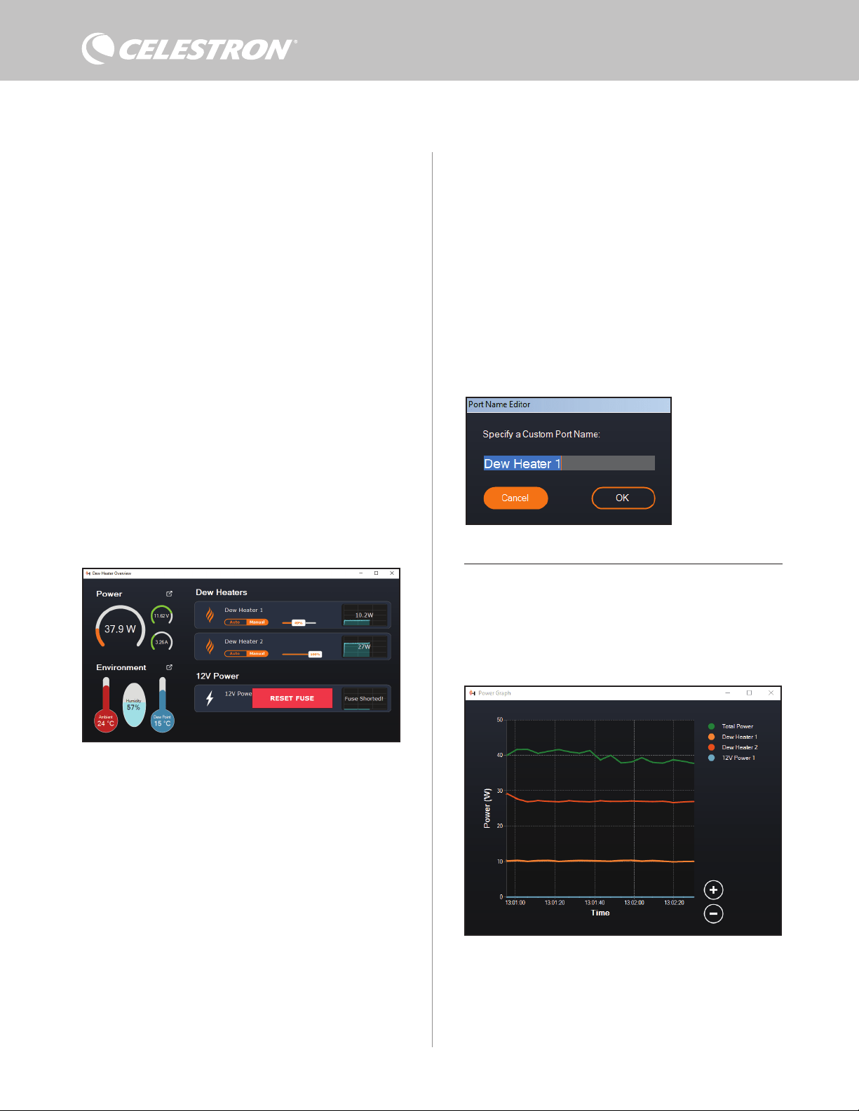
8 | FRANÇAIS
du contrôleur (Figure 14). Les icônes à côté des ports actuellement
utilisés deviendront orange avec la consommation d'énergie au fil
du temps dans le petit graphique à droite. Dans le coin supérieur
gauche de l'écran Aperçu, vous pouvez voir la puissance totale et la
consommation de courant du contrôleur et la tension d'entrée de la
source d'alimentation. En dessous, vous pouvez voir les données de
température et d'humidité ambiantes du capteur environnemental et
le point de rosée calculé.
Le menu Aperçu est également l'endroit où vous pouvez activer ou
désactiver chaque port de sortie, y compris les ports du chauffage
anti-buée et le port d'alimentation de sortie. Si vous vous connectez
à distance au PC connecté au contrôleur, vous pouvez allumer et
éteindre vos appareils à distance ici. Pour le port d'alimentation,
utilisez simplement le bouton ON/OFF. Pour les ports du chauffage
anti-buée, sélectionnez « Manuel » et réglez le niveau de puissance
sur zéro.
Comme indiqué précédemment, le contrôleur fermera
automatiquement ses ports si une charge trop forte est présente
sur l'un des ports (supérieure à 84W) ou si la charge totale sur le
contrôleur dépasse 120W (courant max 10A). Si cela se produit, la
notification de fusible cassé apparaîtra et vous verrez une fenêtre
« RÉINITIALISER FUSIBLE » à côté du ou des ports concernés
dans l'écran Aperçu (Figure 15). Pour réactiver un port après sa
désactivation automatique, réduisez d'abord la charge sur le port
selon les besoins. Ensuite, cliquez sur la case « RÉINITIALISER
FUSIBLE » pour réactiver l'alimentation du port.
REMARQUE: Si la charge totale sur le contrôleur dépasse 120W
(courant max 10A), vous devrez réactiver tous les ports.
Sous chaque port Chauffage anti-buée, vous trouverez des boutons
pour passer du mode de contrôle automatique « intelligent » au mode
de contrôle manuel :
- Si vous sélectionnez le mode manuel, vous devrez indiquer le
niveau de puissance souhaité. Il s'agit d'un nombre compris entre
0 et 100—le pourcentage de puissance maximale du chauffage
anti-buée connecté au port. Une fois que vous avez entré la valeur
souhaitée, appuyez sur ENTRÉE.
l Pour désactiver un port de chauffage anti-buée, sélectionnez
Contrôle manuel et réglez le curseur sur 0%.
- Si vous sélectionnez le mode automatique, vous devrez définir le
niveau « activité ». Il s'agit d'un nombre de 1 (activité la plus faible)
à 10 (activité la plus élevée) qui indique à quel point le contrôleur
intelligent est actif lors de la prévention de la formation de buée. Un
réglage d'activité plus élevé utilisera plus de puissance mais fournira
le plus haut niveau de prévention de la buée lors de conditions
environnementales changeantes. En général, vous pouvez utiliser
un réglage d'activité plus faible pour les sites d'observation
plus chauds et plus secs et un réglage plus élevé pour les sites
d'observation plus frais et plus humides. En outre, utilisez un réglage
d'activité plus élevé pour des ouvertures plus grandes et une activité
plus faible si vous utilisez un pare-buée ou s'il y a du vent. Utilisez le
curseur pour définir l'activité. Si vous n'êtes pas sûr du paramètre
d'activité à utiliser, essayez d'abord 5 (le paramètre par défaut).
Vous pouvez renommer chaque port dans l'écran Aperçu en cliquant
sur le nom du port. La fenêtre Éditeur de nom de port apparaît (Figure
16) et vous pouvez saisir le nouveau nom. Cliquez sur le bouton OK
lorsque vous avez terminé et le nouveau nom apparaîtra pour le port.
Cela vous aidera à garder vos commandes organisées, car vous
pouvez renommer chaque port associé à un appareil connecté. Par
exemple, vous pouvez renommer vos ports « anneau de chauffage
anti-buée de 8 pouces » ou « montage CGX ».
GRAPHIQUE DE PUISSANCE
Sélectionnez « Graphique de puissance » dans le menu Dew Heater
pour afficher la fenêtre Graphique de puissance (Figure 17). Vous
pouvez également accéder au graphique de puissance directement à
partir de l'écran Aperçu en cliquant sur l'icône de flèche de raccourci
à côté du mot « Puissance » dans le coin supérieur gauche de l'écran
Aperçu.
Le graphique de puissance montre la consommation d'énergie au fil
du temps pour tous les appareils connectés aux ports du chauffage
anti-buée et au port d'alimentation de sortie du contrôleur. Chaque
ligne de couleur sur le graphique représente un port différent. Si vous
Fig 17
Fenêtre du graphique de puissance
Fig 15
Si la consommation électrique d'un port dépasse 84 W, le port s'éteindra automatiquement.
Pour le réactiver, réduisez la charge sur le port concerné, puis cliquez sur la case
RÉINITIALISER LE FUSIBLE.
Fig 16
Fenêtre de l’éditeur de nom
de port
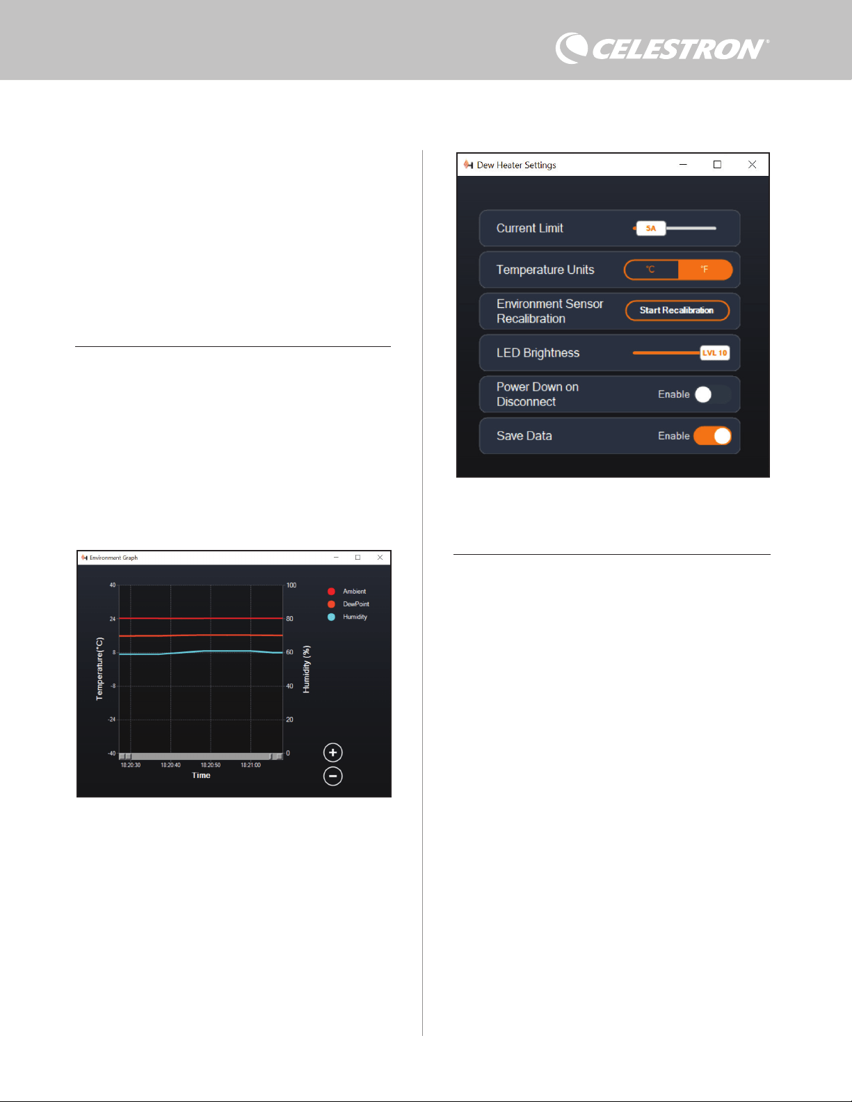
FRANÇAIS | 9
Fig 19
Fenêtre des réglages du chauffage anti-buée
souhaitez changer la couleur d'un port, placez la souris sur le port et
faites un clic droit.
Vous pouvez masquer un port du graphique en cliquant sur le cercle
à gauche du nom du port. Pour réactiver sa ligne sur le graphique, il
suffit de cliquer à nouveau sur le cercle.
Pour « zoomer » sur une plage de temps spécifique sur le graphique
pour voir plus de détails, utilisez les cercles « + » et « - » en bas à
droite du graphique. Vous pouvez également « pincer pour zoomer »
si vous avez un pavé tactile ou utilisez la molette de défilement de
votre souris pour effectuer un zoom avant et arrière. Utilisez le curseur
qui apparaît au bas du graphique pour trouver une plage de temps
particulière.
GRAPHIQUE DE L'ENVIRONNEMENT
Sélectionnez « Graphique d’analyse de l’environnement » dans le
menu Chauffage anti-buée pour afficher la fenêtre Power Graph
(Figure 18). Vous pouvez également accéder au graphique de
l'environnement directement à partir de l'écran Aperçu en cliquant
sur l'icône représentant une flèche de raccourci à côté du mot
« Environnement » sur le côté gauche de l'écran Aperçu. Ce
graphique montre la température de l'air ambiant, l'humidité et le
point de rosée calculé au fil du temps. La température de l'air et le
point de rosée utilisent l'échelle de température en °C à gauche
du graphique. L'humidité utilise l'échelle % d'humidité à droite du
graphique. Chaque ligne de couleur sur le graphique représente une
valeur différente. Si vous souhaitez changer la couleur d'une valeur,
placez la souris dessus et faites un clic droit.
Vous pouvez masquer une valeur du graphique en cliquant sur le
PARAMÈTRES
La sélection « Paramètres » dans le menu Chauffage anti-buée ouvre
la fenêtre Dew Heater Settings (Figure 19).
- Limite actuelle
l Utilisez le curseur pour définir le courant maximum pour
l'alimentation que vous utilisez. Si la consommation d'énergie
du contrôleur dépasse le courant maximum défini, la LED «
Over Current » sur le pont du boîtier du contrôleur s'allumera.
Si cela se produit, vous devrez réduire la consommation
électrique en réduisant ou en éteignant les appareils
connectés au contrôleur. Alternativement, vous pouvez utiliser
une autre alimentation capable de fournir plus de courant. Si
vous faites cela, assurez-vous d'ajuster la limite de courant en
conséquence.
- Unités de température
l Modifiez les unités de température dans CPWI à l'aide des
boutons °C et °F.
- Réétalonnage du capteur d'environnement
l Utilisez le bouton « Démarrer le recalibrage » pour recalibrer le
capteur environnemental. Cela chauffe le capteur pour évaporer
l'humidité qui s'y est accumulée. Le recalibrage permet de
fournir les lectures de capteur les plus précises. Il faut environ
10 minutes pour que le capteur chauffe et refroidisse. Nous
vous recommandons de recalibrer périodiquement le capteur
environnemental, en particulier si le capteur n'a pas été utilisé
depuis un certain temps ou a été stocké dans des conditions
humides. Cela aidera à fournir l'utilisation d'énergie la plus
efficace pour les chauffages anti-buée.
n Si vous mesurez la température ou l'humidité ambiante
pendant le recalibrage, l'écran affichera les dernières
valeurs détectées avant le début du recalibrage.
- Luminosité des LED
l Réglez la luminosité des LED du contrôleur à l'aide du curseur.
Un est le réglage le plus sombre et dix est le plus lumineux.
- Mise hors tension sur déconnexion
l Vous pouvez choisir d'éteindre tous les appareils connectés
lorsque vous déconnectez le contrôleur de CPWI. Pour ce faire,
Fig 18
Fenêtre du graphique environnemental
cercle à gauche du nom de la valeur sur le graphique. Pour réactiver
sa ligne sur le graphique, il suffit de cliquer à nouveau sur le cercle.
Pour « zoomer » sur une plage de temps spécifique sur le graphique
pour voir plus de détails, utilisez les cercles « + » et « - » en bas à
droite du graphique. Vous pouvez également utiliser « pincer pour
zoomer » si vous disposez d'un pavé tactile ou utilisez la molette de
défilement de votre souris pour effectuer un zoom avant et arrière
sur des plages de temps. Utilisez le curseur qui apparaît au bas du
graphique pour trouver une plage de temps particulière.
Pour changer les unités de température de degrés Fahrenheit (par
défaut) en degrés Celsius, utilisez la sélection « Paramètres » dans
le menu Dew Heater.
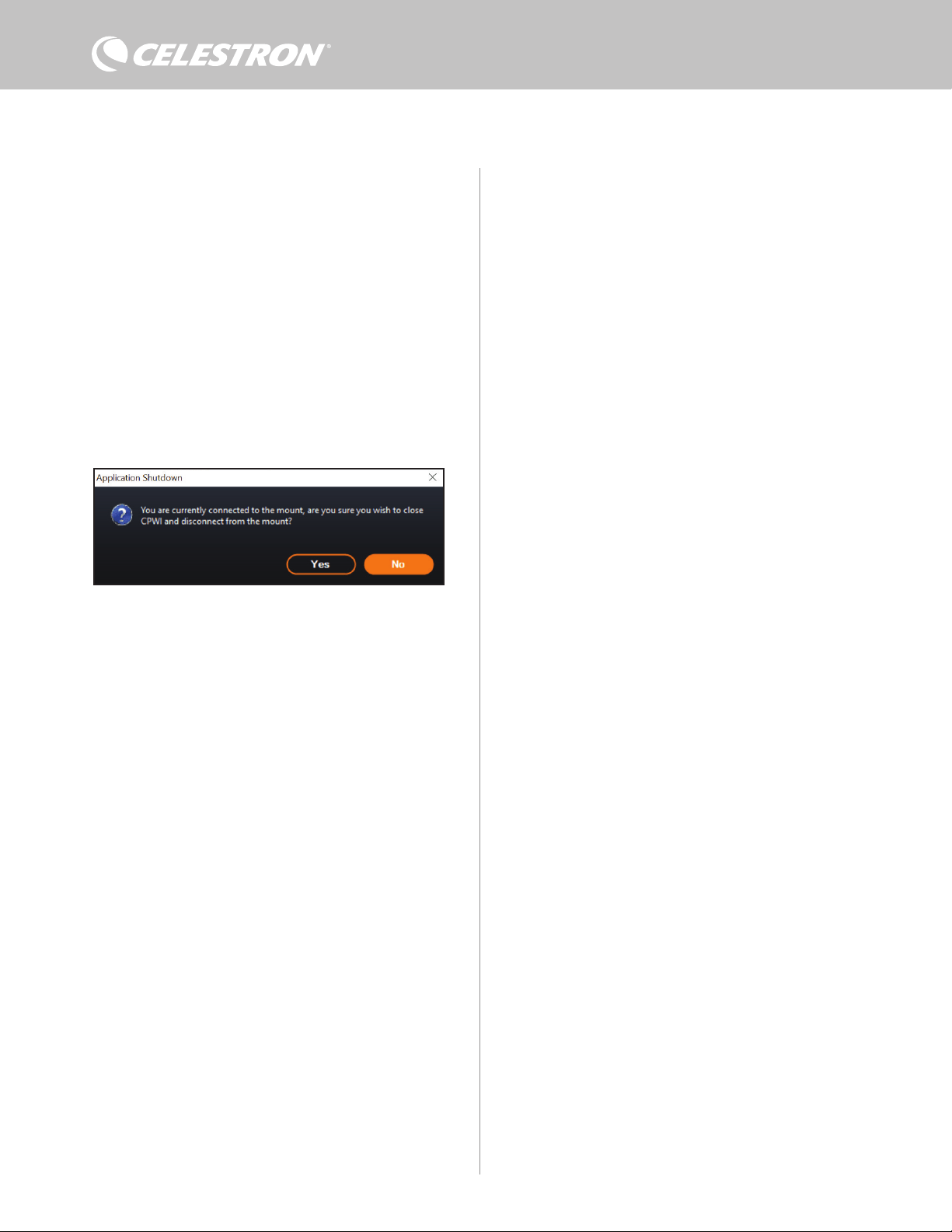
10 | FRANÇAIS
cliquez sur le bouton Activer. Lorsque vous reconnectez CPWI,
tous les ports se réactivent. Si vous n'activez pas cette fonction,
l'alimentation passera par le contrôleur comme d'habitude
lorsque vous vous déconnectez de CPWI.
- Enregistrer les données
l Cette fonctionnalité vous permet d'exporter les données brutes
du contrôleur au format .CSV, que vous pouvez ouvrir dans
Microsoft Excel ou Google Sheets. Si vous sélectionnez cette
option, vous pouvez trouver le fichier .CSV enregistré dans ce
dossier sur votre PC: Documents\Célestron\CPWI
Pour vous déconnecter du contrôleur intelligent double de chauffage
anti-buée à la fin d'une session d'observation, vous pouvez soit fermer
CPWI pour faire apparaître la fenêtre d'arrêt de l'application apparaîtra
(Figure 20), ou vous pouvez sélectionner l'icône « Connexion » dans
le coin supérieur gauche et sélectionner « Déconnecter ». Si vous
avez sélectionné « Mise hors tension sur déconnexion » dans le menu
Chauffage anti-buée>Réglages, tous les appareils connectés au
contrôleur s'éteindront. Sinon, l'alimentation continuera à circuler à
travers les ports du contrôleur comme d'habitude.
9. Spécifications
Poids: 1,2 lbs.
Dimensions: 5,5” x 4,5” x 3,25”
Boîtier Pinces à queue d'aronde et sangle de trépied en aluminium,
refroidies par ventilateur et intégrées
Entrée d’alimentation: 12V DC nominal, tension d'entrée max
13,8V DC, courant d'entrée 10A max, connecteur en barillet fileté à
point positive de 5,5 mm/2,1 mm
Port de sortie d’alimentation: 12V CC, connecteur en barillet
fileté à point positive de 5,5 mm / 2,1 mm, courant de sortie max.
de 7 A
Sorties du chauffage anti-buée: 2x prises jack RCA, 12V CC,
courant de sortie 7A max pour chaque port
Prise Jack de thermistance: 2x prise audio jack 2,5 mm, compatible
avec les anneaux chauffants Chauffage anti-buée Celestron et la
thermistance Celestron en option
Ports AUX: 2x ports AUX, compatibles avec les montures Celestron
et autres produits Celestron
Capteur environnemental: Intégré, donne des données de
température et d'humidité ambiantes, peut être recalibré pour de
meilleures performances
Protection de circuit: fusibles réarmables en interne pour
chaque port, protection contre l'inversion de polarité, sous-tension,
surtension, sous-intensité, surintensité
Micrologiciel: Logiciel évolutif complet Celestron Firmware
Manager (CFM)
Câble d'alimentation: Fiche de connecteur en barillet fileté à pointe
positive de 5,5mm / 2,1mm à une extrémité, prise allume-cigare à
l'autre extrémité, fusible 10A, fil de calibre 16
Fig 20
Fenêtre de fermeture de l’application

FRANÇAIS | 11
Annexe A: Exemples de calculs
d'exigences d'alimentation
CONFIGURATION D’EXEMPLE N°1
- Anneau de chauffage anti-buée Celestron de 8" connecté au port
n°1 du chauffage anti-buée
l Consommation de courant maximale de l'anneau de chauffage
anti-buée de 8’’ = 1,7 A
l Puissance maximale requise pour un anneau de chauffage anti-
buée de 8’’ = 12 V x 1,7 A = 20,4 W
- Monture Celestron Advanced VX EQ connectée au port
d'alimentation #2
l Consommation de courant maximale pour la monture Advanced
VX EQ lors de l'orientation à vitesse maximale = environ 2,0 A
l Puissance maximale requise pour Advanced VX lors de la
rotation à vitesse maximale = 12V x 2,0A = 24,0W
Dans cet exemple, la puissance maximale totale requise par le
contrôleur serait d'environ 48W.
- Si vous avez accès à l'alimentation secteur, l'adaptateur secteur
Celestron-5A, qui peut gérer jusqu'à 60 W, serait un bon choix
pour alimenter le contrôleur.
- Pour les configurations portables, le Celestron PowerTank Lithium
Pro peut fournir jusqu'à 120W de puissance (courant max 10A), il
fonctionnerait donc bien avec cet exemple de configuration.
l La capacité de la pile du PowerTank Lithium Pro est de 158,7
Watt-heures. Le contrôleur utilise environ 48 watts par heure.
Par conséquent, la batterie durera plus de 3 heures dans cet
exemple. Supposons que vous utilisiez le contrôle intelligent
automatique pour l'anneau de chauffage anti-buée. Dans
ce cas, vous pouvez vous attendre à ce que la batterie dure
beaucoup plus longtemps, car l'anneau ne fonctionnera
probablement pas en continu à puissance maximale. De même,
si vous ne faites pas pivoter le télescope de manière répétée
à sa vitesse la plus élevée, la puissance consommée par la
monture sera bien moindre, prolongeant ainsi la durée de vie
de la pile.
EXEMPLE DE CONFIGURATION #2
- Anneau de chauffage anti-buée Celestron de 11" connecté au port
n°1 du chauffage anti-buée
l Consommation de courant maximale de l'anneau de chauffage
anti-buée de 11’’ = 2,5 A
l Puissance maximale requise pour un anneau de chauffage anti-
buée de 11’’ = 12 V x 2,5 A = 30,0 W
- Bande/languette chauffante d'un autre fabricant pour le chercheur
connecté au port #2 du chauffage anti-buée
l Consommation maximale pour la bande/languette chauffante
pour le chercheur = environ 1,0 A
l Puissance maximale requise pour une bande/languette
chauffante pour le chercheur = 12 V x 1,0 A = 12,0 W
- Monture Celestron CGX EQ connectée au port d'alimentation #2
l Consommation de courant maximale pour la monture CGX
EQ lors de l'orientation à vitesse maximale = environ 3,0 A
l Puissance maximale requise pour la monture CGX EQ lors de
la rotation à vitesse maximale = 12V x 3,0A = 36,0W
Dans cet exemple, la puissance maximale totale requise par le
contrôleur serait d'environ 78W.
- Si vous avez accès à une alimentation CA, une alimentation
CA à CC haute puissance fonctionnera bien pour alimenter le
contrôleur. L'adaptateur secteur 5A de Celestron ne fonctionnerait
pas car son maximum est de 60W.
l Si la tension d'alimentation AC-DC est variable, assurez-
vous de la régler sur 12V avant de la connecter au contrôleur.
N'oubliez pas non plus que la prise d'entrée d'alimentation est
à pointe positive.
- Pour les configurations portables, le Celestron PowerTank Lithium
Pro peut fournir jusqu'à 120W de puissance (courant max 10A),
il fonctionnerait donc bien avec cet exemple de configuration.
Cependant, il se peut qu'il ne dispose pas d'une capacité de
stockage d'énergie suffisante pour l'ensemble de votre session
d'observation.
l La capacité de la pile du PowerTank Lithium Pro est de
158,7 Watt-heures. Le contrôleur utilise environ 78 watts
par heure. Par conséquent, la batterie durera plus de 2
heures dans cet exemple. Supposons que vous utilisiez le
contrôle intelligent automatique pour l'anneau de chauffage
anti-buée. Dans ce cas, vous pouvez vous attendre à ce
que la batterie dure beaucoup plus longtemps, car l'anneau
ne fonctionnera probablement pas en continu à puissance
maximale. De même, si vous ne faites pas pivoter le
télescope de manière répétée à sa vitesse la plus élevée,
la puissance consommée par la monture sera bien moindre,
prolongeant ainsi la durée de vie de la pile.
- Pour les configurations portables que vous prévoyez d’utiliser une
nuit entière, nous recommandons une « pile marine » 12V CC ou
une autre pile 12V CC portable avec une capacité de stockage
d'énergie élevée.
l Si vous prévoyez une session d’astrophotographie d’une
nuit entière (8 heures) avec cette configuration, vous aurez
besoin d'une pile marine d'une capacité de 78 W x 8 heures
= 624 watts-heures (c'est-à-dire environ 52 ampères-heures
à 12 V CC).
12 | FRANÇAIS
NOTE DE LA FCC: Cet équipement a été testé et jugé conforme aux limites établies pour un dispositif numérique de
classe B, conformément à la section 15 de la réglementation de la FCC. Ces limites sont conçues pour fournir une pro-
tection raisonnable contre les interférences nuisibles dans une installation résidentielle. Cet équipement génère, utilise
et peut émettre une énergie de fréquence radio et, s’il n’est pas installé et utilisé conformément aux instructions, peut
causer des interférences nuisibles aux communications radio. Mais il n'existe aucune garantie que des interférences ne
seront pas produites dans une installation particulière. Si cet équipement cause des interférences nuisibles à la réception
radio ou télévision, ce qui peut être déterminé en éteignant et en rallumant l'équipement, l'utilisateur est encouragé à
essayer de corriger l'interférence par une ou plusieurs des mesures suivantes:
• Réorientez ou déplacez l'antenne de réception.
• Augmentez la séparation entre l'équipement et le récepteur.
• Branchez l'équipement dans une prise sur un circuit différent de celui auquel le récepteur est connecté.
• Consultez le revendeur ou un technicien radio / TV expérimenté pour obtenir de l'aide
Cet appareil respecte la section 15 des règles de la FCC. Son utilisation est sujette aux deux conditions suivantes: (1)
Cet appareil ne doit pas causer d'interférences nuisibles et (2) cet appareil doit accepter toutes les interférences reçues,
y compris celles pouvant entraîner un fonctionnement indésirable.
Notez que les changements ou les modifications non expressément approuvée par le fournisseur de cet appareil annule
l'autorité de l'utilisateur à utiliser cet appareil.
L'apparence et les caractéristiques techniques du produit sont sujettes à modification sans préavis.
Ce produit est conçu et prévu pour être utilisé par des personnes âgées de 14 ans et plus.
Fabriqué en Chine
©2022 Celestron. Celestron et le Symbol sont des marques déposées de Celestron, LLC •
Tous droits réservés. • Celestron.com • 2835 Columbia Street, Torrance, CA 90503 É.-U
celestron.com/pages/technical-support
10-22
celestron.com/pages/war ranty
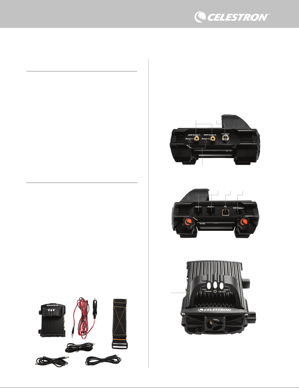
DEUTSCH | 1
Herzlichen Glückwunsch zum Kauf der Intelligenten
Tauheizungssteuerung 2x von Celestron. Diese Steuerung
bietet eine „intelligente“ und effiziente Energienutzung für bis zu
zwei Tauheizungen Ihres Teleskopsystems sowie ein weiteres
12-V-Gleichstromgerät – sie sorgt gleichzeitig für Kabelmanagement
Ihrer Ausrüstung. Wenn Sie Ihre Tauheizungen an die Steuerung
anschließen, verbindet ein Kabel alle mit Ihrer Stromquelle, während
ein anderes die Ausrüstung mit Ihrem PC verbindet, falls gewünscht.
Wenn Sie es vorziehen, keine Verbindung zu einem PC herzustellen,
schließen Sie Ihre Tauheizungen einfach an die Steuerung an
und schalten Sie sie ein. Die Steuerung überwacht automatisch
die Umgebungstemperatur und die Luftfeuchtigkeit mit Hilfe
des integrierten Umgebungssensors. Der Thermistoranschluss
überwacht die Temperatur des Objektivs und lässt nur so viel Strom
fließen, dass eine Betauung verhindert wird. Wenn Sie Akkus
verwenden, reduziert dieses „intelligente“ System den Strombedarf
der Heizungen erheblich und verlängert so die Akkulebensdauer.
Wenn Sie Einstellungen manuell vornehmen oder Daten überwachen
möchten, schließen Sie einen PC oder die Handsteuerung Ihrer
Celestron-Montierung an.
1. Teileübersicht
2. Steuerungsübersicht
INHALTSVERZEICHNIS
Abb. 1 – Alle mitgelieferten Artikel
In Abbildung 2 finden Sie eine Übersicht über die Eingangs- und
Ausgangsanschlüsse sowie die Funktionen der Intelligenten
Tauheizungssteuerung 2x.
Wenn Teile in der Teileliste fehlen, wenden Sie sich bitte für Hilfe an
die technische Unterstützung von Celestron unter www.celestron.
com/pages/technical-support.
1. Teileübersicht
. . . . . . . . . . . . . . . . . . . . . . . . . . . . . . . . . . . . . . . . . . .
S.1
2. Steuerungsübersicht . . . . . . . . . . . . . . . . . . . . . . . . . . . . . . . . . . . . . S.1
3. Befestigung der Steuerung an Ihrer Ausrüstung. . . . . . . . . . . . . . S.3
4. Steuerung mit Strom versorgen . . . . . . . . . . . . . . . . . . . . . . . . . . . S.4
5. Anschluss an eine Celestron-Montierung. . . . . . . . . . . . . . . . . . . . . S.5
6. Verwendung der Steuerung mit einer Celestron-Handsteuerung . S.5
7. Anschluss an einen PC. . . . . . . . . . . . . . . . . . . . . . . . . . . . . . . . . . S.6
8. Steuerung mit CPWI-Software verwenden . . . . . . . . . . . . . . . . . . S.7
9. Technische Daten . . . . . . . . . . . . . . . . . . . . . . . . . . . . . . . . . . . . . . . S.10
Anhang A:
Beispiele für die Ermittlung der
Stromversorgungsanforderungen . . . . . . . . . . . . . . . . . . . . . . . . . . . S.11
INTELLIGENTE TAUHEIZUNGSSTEUERUNG 2X
BEDIENUNGSANLEITUNG
Modell-Nr. 94035
DEUTSCH
1. Tauheizungssteuerungs-Anschlüsse
2. Stromeingangsbuchse
3. Thermistoranschlüsse
4. AUX-Anschlüsse
5. PC-Anschluss
6. Stromausgangsanschluss
7. Brücke
1. 2.
3.
4.
5.
6.
Abb. 2-1
Abb. 2-2
Abb. 2-3
2.
3.
1.
6.
7.
5. 4.
1. Intelligente Tauheizungssteuerung 2x
2. Stromkabel
3. Zusatzkabel
4. Stromkabel der Montierung
5. Stativbein-Gurt
6. Thermistorkabel
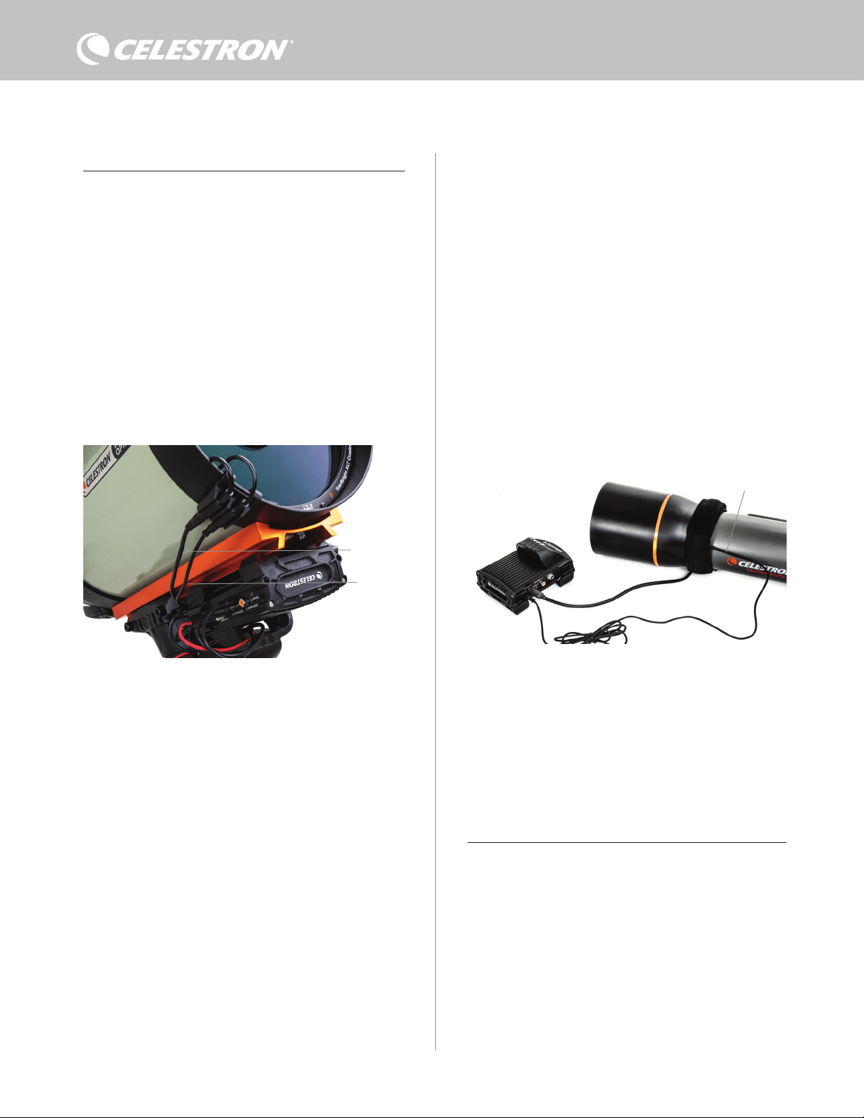
2 | DEUTSCH
TAUHEIZUNGSSTEUERUNG
Die Intelligente Tauheizungssteuerung 2x bietet eine automatische
„intelligente“ Steuerung für bis zu zwei Tauheizmanschetten oder
Tauheizbänder/-streifen.
Wenn Sie die Steuerung mit einer Celestron-Tauheizmanschette
verwenden, verbinden Sie die Stromeingangsbuchse der Manschette
mit einem der Tauheizungsausgänge der Steuerung und dem mit
der Manschette mitgelieferten Verlängerungskabel. Stecken Sie
dann das mitgelieferte Thermistorkabel in die Thermistorbuchse der
Manschette und in den entsprechenden Thermistoranschluss an der
Steuerung. (Abbildung 3) Der Thermistor zeigt die Temperatur der
Schmidt-Korrekturlinse an. Die Steuerung verwendet diese Daten
zusammen mit den Informationen des integrierten Umgebungssensors
(d. h. Umgebungstemperatur und Luftfeuchtigkeit), um die
Manschette mit der richtigen Stromstärke zu versorgen, um eine
Betauung zu verhindern. Bei Akkubetrieb verlängert dieses System
die Akkulebensdauer in den meisten Situationen erheblich. Sobald
Sie die Manschette an einen der Tauheizungsanschlüsse der
Steuerung anschließen, beginnt er sich zu erwärmen (es sei denn,
der Anschluss wurde manuell deaktiviert, worauf später in diesem
Handbuch eingegangen wird).
Wenn Sie die automatische intelligente Steuerung für mehr als
eine Celestron-Tauheizmanschette verwenden möchten, benötigen
Sie ein zusätzliches Thermistorkabel. Das Thermistorkabel ist
ein standardmäßiges 2,5-mm-Audiokabel, das in den meisten
Elektronikgeschäften erhältlich ist. Achten Sie darauf, dass das Kabel
lang genug für Ihre Ausrüstung ist.
Der Umgebungssensor der Steuerung befindet sich in der „Brücke“
am Steuerungsgehäuse (Abbildung 2). Diese Position schützt
den Sensor vor der Wärmeabstrahlung des Gehäuses und sorgt
gleichzeitig für einen guten Luftstrom. Ein integrierter Umweltsensor
ermöglicht eine einfachere, sauberere Ausrüstung, ohne dass externe
Sensoren im Weg sind.
Sie müssen den Umgebungssensor von Zeit zu Zeit neu kalibrieren.
Durch die Neukalibrierung wird der Sensor aufgeheizt, sodass die
angesammelte Feuchtigkeit verdunstet und genaueste Temperatur-
und Luftfeuchtigkeitsdaten sowie die effizienteste Energienutzung
gewährleistet sind. Wir empfehlen eine Neukalibrierung vor der ersten
Verwendung und nach längerer Lagerung in feuchter Umgebung.
Das Verfahren ist einfach; wir erklären es später in diesem Handbuch.
Wenn Sie die automatische intelligente Steuerung nicht
verwenden möchten, können Sie die Leistung für jeden der
Tauheizungsanschlüsse manuell von 0 % (Aus) bis 100 % (volle
Leistung) einstellen. Wir behandeln diese Option später in diesem
Handbuch ausführlicher.
Wenn Sie ein Heizband oder -streifen verwenden, das nicht von
Celestron stammt, benötigen Sie einen Cinch-Stecker für den
Anschluss an die Heizungsausgänge der Steuerung. Sie haben zwei
Möglichkeiten zur Steuerung von Heizbändern und -streifen anderer
Hersteller:
1. Sie können den optionalen Thermistor für Intelligente
Tauheizungssteuerungen von Celestron erwerben, um eine
automatische, intelligente Leistungssteuerung zu ermöglichen.
Schließen Sie das Heizband an das Teleskop an und verbinden
Sie seinen Stecker mit einem der Tauheizungsanschlüsse.
Platzieren Sie dann die Spitze des Thermistors unter dem
Heizband, sodass er gesichert ist (Sie können eventuell
Klebeband verwenden). Verbinden Sie den Stecker des
Thermistors mit der entsprechenden Buchse an der Steuerung
(Abbildung 4). Der Thermistor des Fühlers nicht so genau wie der
in der Tauheizmanschette von Celestron eingebaute Thermistor,
der direkt mit der Korrekturlinse in Kontakt ist. Dennoch ermöglicht
er eine automatische, intelligente Steuerung von Heizbändern/-
streifen.
2. Sie können alternativ, wie bereits erwähnt, die Ausgangsleistung
für jeden Tauheizungsanschluss manuell von 0 % bis 100 %
einstellen.
Jeder der Tauheizungsanschlüsse kann eine maximale Leistung von
84 W (7 A max. Strom) liefern, was für die meisten Taupunktheizungen
mehr als ausreichend sein sollte. Wenn eine angeschlossene
Tauheizung mehr als 84 W benötigt, schaltet sich der Anschluss
automatisch ab, um die Schaltung zu schützen. Nachdem Sie die
Last reduziert haben, kann der Anschluss wieder aktiviert werden.
Dieser Prozess wird später in diesem Handbuch behandelt.
LEISTUNGSSTEUERUNG
Eine praktische Funktion der Intelligenten Tauheizungssteuerung 2x
ist ihre Fähigkeit, ein externes Gerät mit 12 VDC zu versorgen. Viele
Benutzer entscheiden sich dafür, ihre Montierung auf diese Weise
mit Strom zu versorgen, sodass Sie Ihre Tauheizung und Montierung
über eine einzige Stromquelle betreiben können.
Um ein 12-V-Gleichstromgerät mit Strom zu versorgen, verwenden
Sie das mitgelieferte Stromkabel der Montierung – ein Kabel mit
12-VDC-Hohlsteckern an beiden Enden (Abbildung 1). Verbinden
Sie einfach den Stromeingang des Geräts mit dem 12-VDC-Ausgang
der Steuerung. Für den Anschluss ist ein 12-VDC-5,5-mm-/2,1-
mm-Hohlstecker (Spitze ist der Pluspol) erforderlich. Ein Ende des
Stromkabels für die Montierung hat eine integrierte Mutter an seinem
Hohlstecker. Sie können diese an der Stromversorgungsbuchse
von Celestron-Montierungen mit Hohlstecker-Gewindebuchse
festschrauben, um eine möglichst sichere Verbindung zu
Abb. 3
Schließen Sie eine Tauheizmanschette von Celestron mit dem mitgelieferten
Verlängerungskabel und dem Thermistorkabel an die Steuerung an.
Abb. 4
Wenn Sie ein Heizband oder einen Heizstreifen eines anderen Herstellers verwenden,
benötigen Sie den optionalen Celestron-Thermistor für Intelligente Tauheizungssteuerungen.
Celestron-Thermistor
Verlängerungskabel
Thermistorkabel
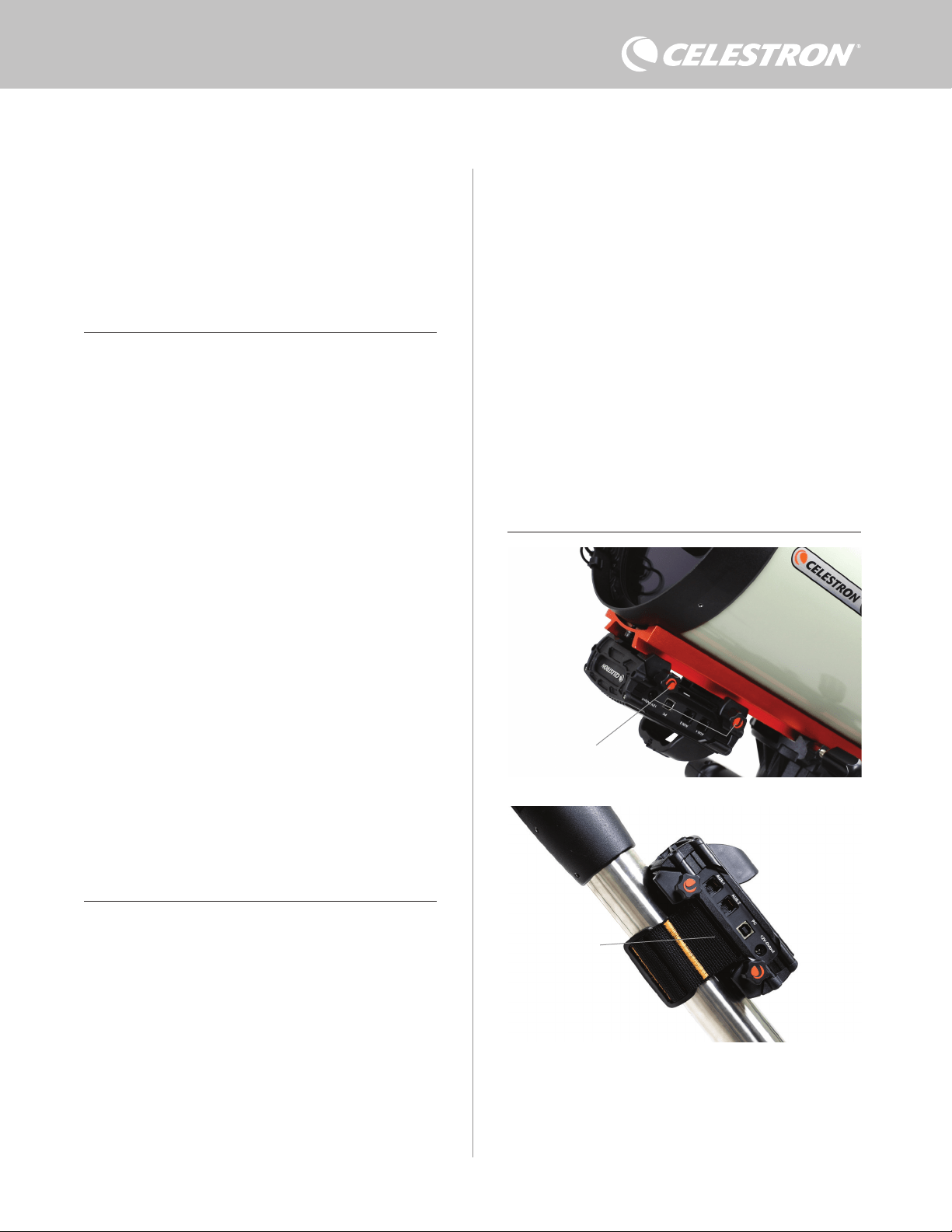
DEUTSCH | 3
– Verwenden Sie die integrierte Schwalbenschwanzklemme,
um die Steuerung an eine CG-5/Vixen oder CGE/Losmandy
Schwalbenschwanzschiene anzuschließen. Wenn Sie sich an Ihrem
optischen Tubus eine Schwalbenschwanzschiene befindet, ist dies
vielleicht die einfachste und bequemste Art, die Steuerung mit Ihrer
Ausrüstung zu verbinden. Lösen Sie einfach die Klemmknöpfe
der Steuerung, setzen Sie die Klemmen der Steuerung auf die
Schwalbenschwanzschiene und ziehen Sie die Klemmknöpfe fest an
(Abbildung 5).
– Verwenden Sie den mitgelieferten Stativbein-Gurt, um die Steuerung
an einem der Stativbeine zu befestigen. Führen Sie den Gurt
durch die Schlitze auf der Unterseite des Steuerungsgehäuses,
wickeln Sie den Gurt um eines der Stativbeine, ziehen Sie den
Gurt mit der Schnalle fest und sichern Sie das Gurtende mit den
Klettverschlüssen am Gurt (Abbildung 6).
– Wenn die Zubehörablage Ihres Stativs groß genug ist, können Sie die
Steuerung auf die Ablage legen. Beachten Sie bei dieser Methode,
dass das Steuerung nicht gesichert ist. Seien Sie vorsichtig und
ziehen Sie nicht mit Gewalt an den Kabeln.
HINWEIS: LEGEN SIE DIE STEUERUNG NICHT AUF DEN
BODEN! Wasser und Schmutz können in die Steuerung eindringen
und können Elektrikprobleme verursachen.
VERWENDUNG DER BRÜCKE FÜR DIE KABELVERLEGUNG
Die Brücke am Gehäuse enthält den Umgebungssensor der
Steuerung und schützt ihn vor abgestrahlter Wärme, um möglichst
genaue Daten zur Umgebungstemperatur und Luftfeuchtigkeit
zu liefern. Wir haben die Brücke auch für die Kabelverlegung
entwickelt. Sie können die Kabel unterhalb der Brücke verlegen, um
sie aufgeräumt zu halten und vor Verlust zu schützen (Abbildung 7).
gewährleisten. Der Strom fließt durch den Anschluss, sobald Sie das
Gerät anschließen; es ist nicht nötig, den Anschluss einzuschalten
(es sei denn, Sie haben den Anschluss zuvor deaktiviert, worauf wir
später noch eingehen werden).
Der Stromanschluss liefert eine maximale Leistung von 84 W (7 A max.
Strom). Wenn ein angeschlossenes Gerät mehr als 84 W benötigt,
schaltet sich der Anschluss automatisch ab, um die Schaltkreise zu
schützen. Der Anschluss kann wieder aktiviert werden, nachdem Sie
die Last reduziert haben. Dieser Vorgang wird später behandelt.
STATUS-LEDS
Auf der Brücke befinden sich drei LEDs, die den Status der
Steuerung anzeigen:
– Die mittlere LED zeigt an, ob Strom zur Steuerung fließt.
– Die LED mit der Aufschrift „Over Current“ (Überstrom) leuchtet
auf, wenn die Stromaufnahme größer ist, als die Stromversorgung
liefern kann. Trennen Sie in diesem Fall entweder eines der an
die Steuerung angeschlossenen Geräte, reduzieren Sie ihre
Stromaufnahme oder verwenden Sie eine Stromquelle, die mehr
Strom liefern kann. Sie müssen die max. Stromaufnahme für Ihre
Stromversorgung festlegen, damit diese LED richtig funktioniert
(wie später in diesem Handbuch beschrieben).
l Wenn es an einem der Anschlüsse zu einem Kurzschluss
durch ein angeschlossenes Gerät gekommen ist, blinkt
die „Over Current“ (Überstrom)-LED und der betroffene
Anschluss schaltet sich ab. Sie müssen die Anweisungen
befolgen, die später im Handbuch beschrieben werden, um
den Anschluss erneut zu aktivieren und zu verwenden.
– Die LED mit der Aufschrift „Under Voltage“ (Unterspannung)
leuchtet auf, wenn die Eingangsspannung der Steuerung weniger
als 11,0 V Gleichspannung beträgt. Dies kann der Fall sein, wenn
Ihr Akku kurz vor dem Ende seiner Ladekapazität steht. In diesem
Fall müssen Sie eine andere Stromversorgung verwenden oder
den Akku aufladen. Die Unterspannungs-LED schützt Ihren Akku
davor, dass er zu stark entladen wird, was seine Lebensdauer
verkürzen könnte.
l Wenn die Eingangsspannung der Stromversorgung 13,8 V
übersteigt, schalten sich alle Ausgänge ab, um die Schaltung
zu schützen und die LED „Under Voltage“ (Unterspannung)
blinkt. In diesem Fall müssen Sie die Stromversorgung
durch eine ersetzen, die weniger als 13,8 V liefert. Alle
Ausgangsanschlüsse müssen außerdem gemäß den
Anweisungen in diesem Handbuch manuell wieder aktiviert
werden.
Wenn Sie bei dunklem Himmel die LEDs als zu hell empfinden,
können Sie ihre Helligkeit anpassen. Wie das geht, erklären wir
später in dieser Bedienungsanleitung.
ZUSÄTZLICHER STROMKREISSCHUTZ
Zusätzlich zu den Warnungen der Status-LEDs verfügt die Intelligente
Tauheizungssteuerung 2x über weitere Stromkreisschutzmaßnahmen,
um die Sicherheit Ihrer Geräte zu gewährleisten.
Wenn die Gesamtleistungsaufnahme der Steuerung 120 W (10 A
max. Strom) überschreitet, schaltet sich die Steuerung automatisch
ab. Verringern Sie die Last an der Steuerung und aktivieren Sie die
Anschlüsse manuell gemäß den Anweisungen, die später in dieser
Bedienungsanleitung beschrieben werden.
Wenn Sie die Eingangsstromquelle versehentlich mit falscher
Polarität anschließen, schaltet sich die Steuerung nicht ein, um
Schäden am Schaltkreis zu vermeiden.
3. Befestigung der Steuerung an Ihrer
Ausrüstung
Legen Sie fest, wie Sie die Steuerung an Ihrem Teleskop befestigen
möchten. Es gibt mehrere Möglichkeiten:
Abb. 6
Schlitz für Stativgurt
Abb. 5
Klemmknöpfe

4 | DEUTSCH
Führen Sie einfach das Kabelende unterhalb der Brücke ein und
ziehen Sie es hindurch, bis genügend Spielraum vorhanden ist, um
den Stecker des Kabels mit dem entsprechenden Anschluss an der
Steuerung zu verbinden.
4. Steuerung mit Strom versorgen
Sie benötigen ein geeignetes 12-VDC-Netzteil für die Intelligente
Tauheizungssteuerung 2x. Ein angemessenes 12-VDC-Netzteil
hängt von den Geräten ab, die Sie an das Steuerung angeschlossen
haben. Die max. Leistung der Steuerung beträgt 120 W (10 A max.
Strom bei 12 VDC), aber viele Anwendungsfälle erfordern weniger
Leistung. Bei der Auswahl eines Netzteils ist es wichtig, die ungefähre
Leistung zu ermitteln, die Sie für Ihre Ausrüstung benötigen und die
Akkukapazität zu bestimmen, die Sie für Ihre Beobachtungssession
benötigen.
Hilfreiche Formeln:
– Spannung (in Volt) x Strom (in Ampere) = Leistung (in Watt)
– Strom (in Ampere) x Zeit (in Stunden) = erforderliche Akkukapazität
(in Amperestunden)
– Leistung (in Watt) x Zeit (in Stunden) = erforderliche Akkukapazität
(in Wattstunden)
Die max. Eingangsspannung an der Stromeingangsbuchse beträgt
13,8 VDC. Stellen Sie sicher, dass die Ausgangsspannung Ihres
Netzteils diesen Wert nicht überschreitet. Bei einer Spannung von
mehr als 13,8 VDC werden alle Ausgänge automatisch abgeschaltet,
um die Schaltkreise zu schützen und die Status-LED „Over Voltage“
(Überspannung) auf der Brücke des Gehäuses blinkt.
Sie müssen zwischen den folgenden Stromversorgungsoptionen
wählen:
– Für tragbare Ausrüstungen benötigen Sie einen 12-VDC-Akku.
Sowohl der PowerTank Lithium Pro als auch der PowerTank 17AH
von Celestron sind geeignet. Verwenden Sie das mitgelieferte
Stromkabel und schließen Sie den Zigarettenanzünderstecker am
Akku und den Gewindestecker an der Steuerung an (Abbildung 8).
HINWEIS: Wenn Sie zwei Tauheizungen bei starker Betauung
verwenden und zusätzlich ein 12-V-Gleichstromgerät betreiben,
kann es passieren, dass die Steuerung in der Nähe ihrer
Leistungsgrenze von 120 W (10 A Strom) arbeitet. In diesem
Fall haben der PowerTank Lithium Pro und der PowerTank 17Ah
möglicherweise nicht genug Kapazität, um Ihre Ausrüstung die
ganze Nacht lang zu betreiben. Sie benötigen dann einen Akku
mit größerer Kapazität.
– Wenn eine Netzsteckdose zur Verfügung steht, können Sie ein
12-VDC-Netzteil verwenden. Wenn Ihre Ausrüstung eine Leistung
von 60 W oder weniger (5 A Stromstärke oder weniger) benötigt,
können Sie das 5-A-Netzteil von Celestron verwenden. Die
sicherste Verbindung erhalten Sie, wenn Sie das Ausgangskabel
des Netzteils an die Stromeingangsbuchse der Steuerung
anschließen, den Stecker am Ende des Kabels in die Außenseite der
Buchse schrauben und dann das Netzteil an eine Netzsteckdose
anschließen (Abbildung 9).
WARNHINWEIS: DIE MAXIMALE LEISTUNG, DIE
DIE EINGANGSBUCHSE AUFNEHMEN KANN,
BETRÄGT 120 W (10 A MAX. STROM BEI 12 V). Wenn
Sie eine Stromquelle, die mehr als 120 W liefern kann,
an die Stromeingangsbuchse anschließen, könnten Sie
das Stromkabel der Steuerung und die Steuerung selbst
beschädigen. Wenn Sie mehr als 120 W benötigen, empfehlen
wir den Kauf der Intelligenten Tauheizungssteuerung von
Celestron und der Leistungssteuerung 4x, die bis zu 240 W
(20 A max. Strom) liefern kann.
HINWEIS: Bei Betrieb im Bereich des maximalen Stroms von
10 A kommt es aufgrund des Versorgungskabels zu einem
Spannungsabfall von ca. 1 V zwischen Stromquelle und Steuerung.
In diesem Fall raten wir zur Verwendung einer Stromquelle, die
etwas mehr als 12 V (aber weniger als 13,8 V) liefert.
In Anhang A finden Sie Beispiele für Stromversorgungskonfigurationen
als Referenz.
Wenn Sie sich für ein Netzteil entschieden haben, müssen Sie
die max. Stromaufnahme für Ihr Netzteil mit Hilfe der Celestron-
Handsteuerung oder CPWI einstellen (später in dieser
Bedienungsanleitung beschrieben). Wenn die Steuerung dann mehr
Strom aufnimmt als der von Ihnen festgelegte Höchstwert, leuchtet
die LED „Over Current“ (Überstrom) auf. Standardmäßig beträgt die
Abb. 8
Sie können das mitgelieferte Stromkabel verwenden, um einen Akku an die Steuerung
anzuschließen. Verwenden Sie den Hohlstecker-Gewindeanschluss, um eine sichere
Verbindung zu gewährleisten.
PowerTank Lithium Pro
Stromkabel
Hohlstecker-Gewindeanschluss
Die Brücke des Gehäuses wurde so konzipiert, dass sie die Kabelverlegung erleichtert.
Abb. 7
Abb. 9
Hohlstecker-Gewindeanschluss
5-A-Netzteil
Wenn Sie einen Strom von 5 A (60W) oder weniger für Ihre Ausrüstung benötigen
und Zugang zu einer Netzsteckdose haben, können Sie den Celestron AC Adapter-5A
zur Stromversorgung der Steuerung verwenden. Verwenden Sie den Hohlstecker-
Gewindeanschluss, um eine sichere Verbindung zu gewährleisten.

DEUTSCH | 5
max. Stromaufnahme 2,0 A, was relativ niedrig ist. Wenn Sie also
nicht die max. Stromaufnahme für Ihre Stromquelle eingestellt haben,
kann diese LED vorzeitig aufleuchten.
Wenn Sie die Stromversorgung an die Stromeingangsbuchse
anschließen, schaltet sich die Steuerung ein. Strom sollte durch die
Anschlüsse fließen.
5. Anschluss an eine Celestron
Montierung
Wenn Sie die Intelligente Tauheizungssteuerung 2x mit einer
Celestron-Montierung verwenden, können Sie sie an die Montierung
anschließen, um Einstellungen zu ändern und Daten mit der
Handsteuerung der Montierung zu überwachen. Dies ist eine
hervorragende Option für Ausrüstungen ohne PC-Anschluss.
Bevor Sie die Handsteuerung Ihres Teleskops mit der Intelligenten
Tauheizungssteuerung 2x verwenden können, müssen Sie
eventuell die Firmware Ihrer Handsteuerung aktualisieren. Für
die NexStar+ Handsteuerung benötigen Sie Firmwareversion
5.33.1333 oder höher. Für die StarSense Handsteuerung benötigen
Sie Firmwareversion 1.22.21333 oder höher. Sie können die
Versionsnummer Ihrer Firmware überprüfen, indem Sie die MENU-
Taste drücken und mit den SCROLL-Tasten und ENTER zu „Hand
Control>Get Version Info“ (Handsteuerung>Versionsinfo abrufen)
navigieren. Verwenden Sie die Firmware-Manager (CFM) Software
von Celestron, um die Firmware zu aktualisieren, falls erforderlich.
Die neueste Version finden Sie hier: https://www.celestron.com/
pages/drivers-and-software
Um die NexStar+ oder StarSense Handsteuerung zu verwenden,
verbinden Sie das mitgelieferte AUX-Kabel mit einem AUX-Anschluss
an der Celestron-Montierung und einem AUX-Anschluss an der
Intelligenten Tauheizungssteuerung 2x. Schließen Sie dann die
Handsteuerung der Montierung wie gewohnt an die Montierung
an. Alternativ können Sie die Handsteuerung auch direkt an einen
der AUX-Anschlüsse der Steuerung anschließen. Sie können
auch das mitgelieferte Stromkabel der Montierung verwenden, um
die Montierung über den Stromausgang mit Strom zu versorgen
(Abbildung 10).
HINWEIS: Die AUX-Anschlüsse werden nur dann mit Strom versorgt,
wenn eine Celestron-Montierung an einen der AUX-Anschlüsse
angeschlossen und eingeschaltet ist. Wenn Sie keine Celestron-
Montierung angeschlossen haben, wird eine Handsteuerung, die
direkt an einen der AUX-Anschlüsse angeschlossen ist, nicht mit
Strom versorgt.
6. Verwendung der Steuerung mit einer
Celestron-Handsteuerung
Nach dem Anschluss können Sie mit der NexStar+ oder StarSense
Handsteuerung Einstellungen ändern und Daten überwachen.
Schalten Sie dazu die Montierung ein, drücken Sie die MENU-Taste
an der Handsteuerung, navigieren Sie mit den SCROLL-Tasten
zum Tauheizung-Menü und drücken Sie ENTER. Verwenden Sie
nun die SCROLL-Tasten, um die Menüoptionen für die Tauheizung
anzuzeigen und wählen Sie mit ENTER aus.
Abbildung 11 zeigt den Menübaum der Tauheizung.
HINWEIS: Wenn Sie die StarSense Handsteuerung verwenden,
müssen Sie die SCROLL-Tasten verwenden, um den gesamten Text
für einige Menüauswahlen anzuzeigen.
Dew Heater Input Power
Power Status
Voltage Status
Current Status
Current Limit
Dew Heater #1
Dew Heater #2
Power #1
Ambient Temp
Humidity
Dew Point
Recalibration
Dew Heater Ports
Power Ports
Environment
Handsteuerung Tauheizung-Menübaum
Abb. 11
Abb. 10
Das mitgelieferte AUX-Kabel ermöglicht die Kommunikation der Montierung mit der Steuerung. Sie
können auch das mitgelieferte Stromkabel der Montierung verwenden, um die Montierung über
den Stromausgang mit Strom zu versorgen.
AUX-Kabel
Stromkabel der
Montierung

6 | DEUTSCH
EINGANGSLEISTUNG
Wählen Sie diese Option, um die Stromaufnahme der an die
Steuerung angeschlossenen Geräte zu überwachen. Sie können
auch den Eingangsstrom der Stromquelle überprüfen und die max.
Stromaufnahme einstellen. Wählen Sie mit den SCROLL-Tasten
auf der Handsteuerung zwischen den folgenden Optionen aus und
wählen Sie mit ENTER aus.
l Leistungsstatus – Zeigt die Stromaufnahme der an die Steuerung
angeschlossenen Geräte an.
l Spannungsstatus – Zeigt die von der Eingangsstromquelle
gelieferte Spannung an.
l Stromstatus – Zeigt die Stromaufnahme der an die Steuerung
angeschlossenen Geräte an.
l Stromgrenzwert – In diesem Menü können Sie den max. Strom
für die Stromquelle einstellen. Wenn die Stromaufnahme der
angeschlossenen Geräte diesen Wert überschreitet, leuchtet die
LED „Over Current“ (Überstrom) auf der Brücke der Steuerung
auf. Drücken Sie ENTER, um den Stromgrenzwert zwischen 1,0
A und 10,0 A einzustellen. Drücken Sie zum Abschluss erneut
ENTER.
HINWEIS: Wenn Sie den Stromgrenzwert überschreiten und die
LED „Over Current“ (Überstrom) aufleuchtet, müssen Sie ein Gerät
vom Steuerung trennen oder eine andere Stromquelle verwenden,
die mehr Strom liefern kann. Wenn Sie eine andere Stromquelle
verwenden, achten Sie darauf, dass Sie den Stromgrenzwert
ändern.
TAUHEIZUNGSANSCHLÜSSE
Mit dieser Option wird die Stromaufnahme für jeden Anschluss der
Tauheizung angezeigt. Wenn Sie die automatische „intelligente“
Steuerung für die Tauheizung nicht verwenden möchten, können Sie
hier die Leistungsabgabe für jeden Tauheizungsanschluss manuell
einstellen.
Nach der Auswahl der Tauheizungsanschlüsse aus dem Menü
können Sie zu den beiden Heizungsanschlüssen scrollen. Es
wird für jeden Heizungsanschluss wird auf der LCD-Anzeige des
Handschalters angezeigt, ob sich der Anschluss im manuellen oder
automatischen Modus befindet und wie hoch die Leistungsaufnahme
des Anschlusses zu diesem Zeitpunkt ist.
Um vom automatischen in den manuellen Modus zu wechseln, wählen
Sie den Anschluss mit den SCROLL-Tasten aus und drücken Sie
dann ENTER. Wählen Sie dann mit den SCROLL-Tasten zwischen
manuellem und automatischem Modus aus und drücken Sie ENTER.
– Wenn Sie den manuellen Modus wählen, müssen Sie die
gewünschte Leistungsstufe angeben. Dies ist eine Zahl zwischen 0
und 100 – der Prozentsatz der max. Leistung der an den Anschluss
angeschlossenen Tauheizung. Sobald Sie den gewünschten Wert
eingegeben haben, drücken Sie ENTER. Um einen Anschluss für
eine Tauheizung abzuschalten, wählen Sie den Anschluss für den
Tauheizung aus, wechseln Sie in den manuellen Modus und legen
Sie die Leistungsstufe auf 0 % fest.
– Wenn Sie den automatischen Modus wählen, müssen Sie das
Schutzniveau einstellen. Dabei handelt es sich um eine Zahl
von 1 (niedrigster Schutz) bis 10 (höchster Schutz), die angibt,
wie aktiv die Intelligente Tausteuerung bei der Vermeidung von
Tau ist. Ein höheres Schutzniveau benötigt mehr Strom, bietet
aber den höchsten Grad an Tauvermeidung bei wechselnden
Umgebungsbedingungen. Im Allgemeinen können Sie eine
niedrigere Schutzniveaueinstellung für wärmere und trockenere
und eine höhere Einstellung für kühlere und feuchtere
Beobachtungsorte verwenden. Verwenden Sie außerdem eine
höhere Schutzniveaueinstellung für größere Aperturen und eine
niedrigere Schutzniveaueinstellung, wenn Sie einen Tauschutz
verwenden oder es windig ist. Wenn Sie sich nicht sicher sind,
welche Schutzniveaueinstellung Sie verwenden sollen, versuchen
Sie es zunächst mit 5 (Standardeinstellung). Nachdem Sie das
Schutzniveau eingestellt haben, drücken Sie ENTER.
STROMVERSORGUNGSANSCHLUSS
Mit dieser Auswahl können Sie den 12-VDC-Ausgang für ein an den
Stromanschluss angeschlossenes Gerät überwachen.
Wenn ein Gerät an den Anschluss angeschlossen ist und Sie „Power
Port“ (Stromanschluss) aus dem Tauheizung-Menü auswählen,
wird auf der LCD-Anzeige die Stromaufnahme angezeigt. Um
die Stromversorgung des Anschlusses zu deaktivieren und ein
angeschlossenes Gerät auszuschalten, drücken Sie ENTER für
den ausgewählten Anschluss. Auf dem LCD-Bildschirm wird dann
„Disable port?“ (Anschluss deaktivieren?) angezeigt. Drücken
Sie zum Fortfahren ENTER. Wenn Sie die Stromversorgung nicht
deaktivieren möchten, drücken Sie BACK. Um die Stromversorgung
des Anschlusses erneut zu aktivieren und ein angeschlossenes
Gerät einzuschalten, drücken Sie wie0der ENTER.
UMGEBUNG
Mit dieser Auswahl können Sie die Daten des Umgebungssensors
anzeigen. Hier können Sie auch den Sensor für eine optimale
Leistung neu kalibrieren. Verwenden Sie die SCROLL-Tasten auf der
Handsteuerung, um eine der folgenden Optionen auszuwählen und
wählen Sie mit ENTER aus.
l Umgebungstemperatur – Zeigt die Temperatur der Umgebungsluft
an.
l Luftfeuchtigkeit – Zeigt die relative Luftfeuchtigkeit an.
l Taupunkt – Dieser Wert wird in Echtzeit aus den Daten von
Umgebungstemperatur und Luftfeuchtigkeit berechnet. Wenn die
Temperatur des Objektivs unter den angezeigten Wert sinkt, bildet
sich Tau auf seiner Oberfläche.
l Rekalibrierung – Um die Rekalibrierung des Umgebungssensors
zu starten, wählen Sie diese Option und drücken Sie ENTER.
Der Sensor erwärmt sich, um die Feuchtigkeit zu verdampfen,
die sich auf ihm angesammelt hat und liefert so die genauesten
Sensormesswerte. Die Rekalibrierung dauert ca. 10 Minuten ab
dem Zeitpunkt, an dem Sie ENTER drücken und bis der Sensor
wieder auf Umgebungstemperatur abgekühlt ist. Wir empfehlen,
den Umgebungssensor regelmäßig neu zu kalibrieren, vor allem,
wenn der Sensor längere Zeit nicht benutzt oder in feuchter
Umgebung aufbewahrt wurde.
n Wenn Sie die Umgebungstemperatur oder die Luft feuchtigkeit
während der Neukalibrierung überprüfen, werden auf dem
Display die zuletzt vor Beginn der Neukalibrierung ermittelten
Werte angezeigt.
DEAKTIVIERTEN ANSCHLUSS REAKTIVIEREN
Wie bereits erwähnt, werden die Anschlüsse der Steuerung
automatisch abgeschaltet, wenn einer der Anschlüsse mehr als 84 W
(7 A max. Strom) aufnimmt oder wenn die Gesamtlast der Steuerung
120 W (10 A max. Strom) übersteigt. Erneutes Aktivieren eines
Anschlusses, nachdem er automatisch abgeschaltet wurde:
l Verringern Sie zunächst die Last an der Steuerung.
l Drücken Sie zur Auswahl des deaktivierten Anschlusses MENU,
blättern Sie zu „Dew Heater“ (Tauheizung) und drücken Sie ENTER.
Blättern Sie dann zu „Dew Heater Port“ (Tauheizungsanschluss)
oder „Power Port“ (Stromanschluss) und drücken Sie ENTER.
l Auf dem LCD-Bildschirm wird „Reset Fuse?“ (Sicherung
zurücksetzen?) angezeigt. Drücken Sie ENTER, um den
Anschluss wieder zu aktivieren.
HINWEIS: Wenn die Gesamtbelastung der Steuerung 120 W (10 A
max. Strom) übersteigt, müssen Sie alle Anschlüsse erneut aktivieren.
7. Anschluss an einen PC
Bei einigen Ausrüstungen kann es sinnvoll sein, die Intelligente
Tauheizungssteuerung 2x an einen PC anzuschließen, um
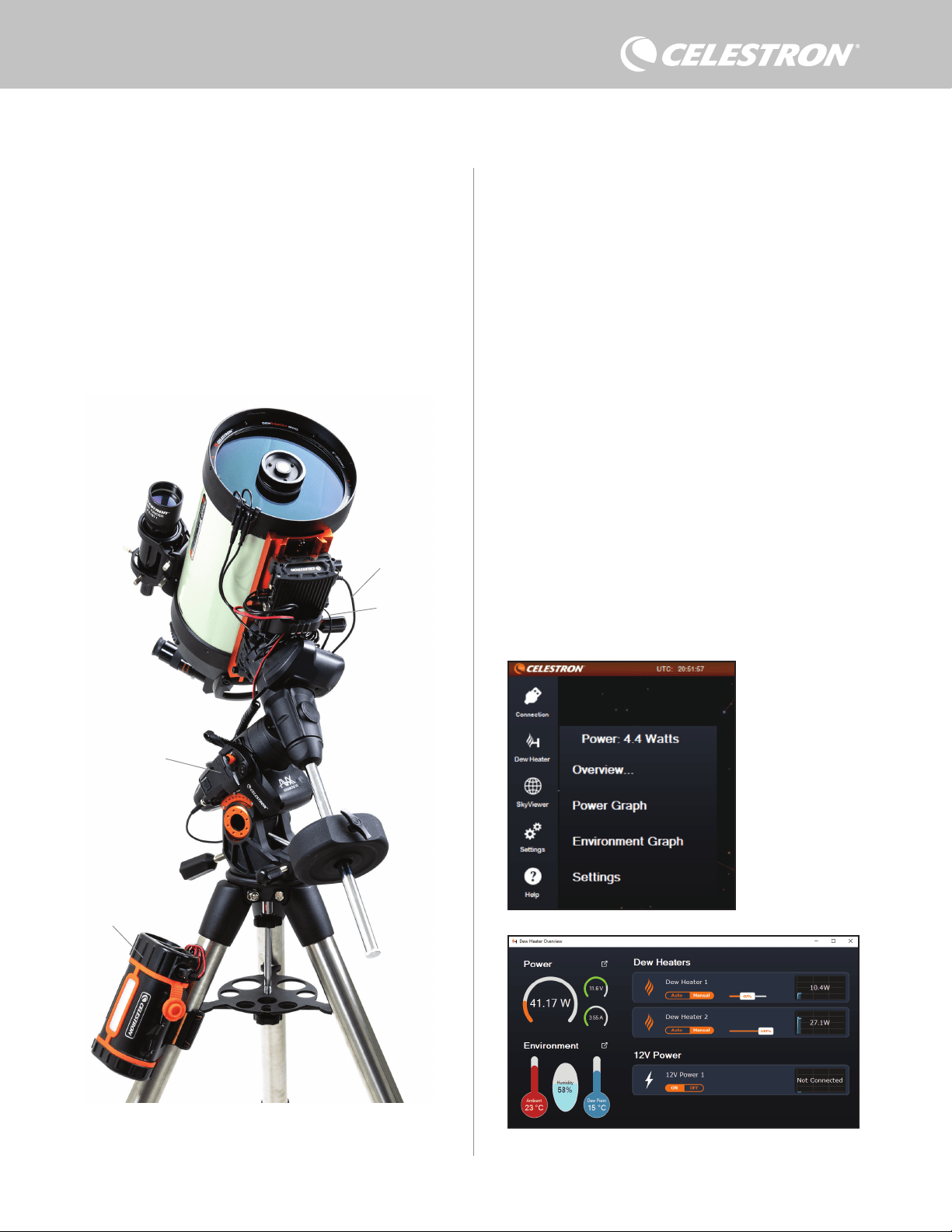
DEUTSCH | 7
Um einen PC über das optionale SkyPortal WLAN-Modul drahtlos
mit der Steuerung zu verbinden, benötigen Sie eine Celestron-
Montierung und das WLAN-Modul (separat erhältlich). Stecken
Sie das WLAN-Modul in einen AUX-Anschluss an der Montierung.
Verbinden Sie einen anderen AUX-Anschluss der Montierung mit
einem der AUX-Anschlüsse der Steuerung über das mitgelieferte
AUX-Kabel. Sie können auch das mitgelieferte Stromkabel der
Montierung verwenden, um Ihre Montierung über einen der
Stromausgänge mit Strom zu versorgen. (Abbildung 12). Sobald alle
Kabel angeschlossen sind, schalten Sie die Montierung ein.
HINWEIS: Wenn Ihre Montierung nur über einen AUX-Anschluss
verfügt, müssen Sie den optionalen AUX-Anschluss-Splitter
erwerben. Dieser wandelt den einzigen AUX-Anschluss der
Montierung in zwei AUX-Anschlüsse um.
8. Steuerung mit CPWI-Software
verwenden
Wenn S ie Ih r Te le skop o der I hre K am era b ere its vo n ein em C om pute r aus
steuern, werden Sie es lieben, die Intelligente Tauheizungssteuerung
2x mit unserer kostenlosen CPWI-Software von Celestron zu
steuern. Um die neueste Version herunterzuladen, besuchen Sie:
https://www.celestron.com/pages/celestron-pwi-telescope-control-
software
Installieren Sie die Software und rufen Sie CPWI auf. Wählen
Sie „Start“, wenn das Startfenster erscheint. Tippen Sie dann auf
das Symbol „Connection“ (Verbindung) in der oberen linken Ecke
des Bildschirms. Wenn Sie eine kabelgebundene Verbindung
verwenden, wählen Sie „Mount USB“ (Montierung USB). Wenn Sie
das SkyPortal WLAN-Modul verwenden, tippen Sie auf das Symbol
„Connection“ (Verbindung) und wählen Sie dann „WiFi“ (WLAN).
CPWI sollte die Steuerung finden und sich mit ihr verbinden. Sobald
die Verbindung hergestellt wurde, erscheint das Tauheizungssymbol
im Auswahlmenü auf der linken Seite des Bildschirms.
Einstellungen vorzunehmen und Daten zu überwachen. Dies
gilt insbesondere, wenn Sie bereits einen PC zur Steuerung
Ihrer Montierung oder von Bildgebungs- oder Führungskameras
verwenden.
Für einen kabelgebundenen Anschluss benötigen Sie ein USB-Typ-
A-auf-Typ-B-Kabel (nicht im Lieferumfang enthalten). Schließen Sie
es an den PC-Anschluss der Steuerung und einen USB-Anschluss
Ihres PCs an. Sobald Sie die Steuerung einschalten, sollte sie vom
Computer erkannt werden.
Wenn Sie eine computergesteuerte Celestron-Montierung
verwenden, können Sie sich mit der Montierung verbinden und sie
über die Intelligente Tauheizungssteuerung mit der kostenlosen
CPWI PC-Software steuern. Verwenden Sie dazu das mitgelieferte
AUX-Kabel, um einen der AUX-Anschlüsse der Steuerung mit einem
der AUX-Anschlüsse der Montierung zu verbinden.
Abb. 13
CPWI-Tauheizungsmenü
Abb. 14
Übersichtsbildschirm
Abb. 12
Wenn Sie eine Celestron-Montierung mit dem SkyPortal WLAN-Modul verwenden, können Sie über
das mitgelieferte AUX-Kabel eine WLAN-Verbindung zur Steuerung über die Montierung herstellen.
Sie können auch das mitgelieferte Stromkabel der Montierung verwenden, um die Montierung über
den Stromausgang mit Strom zu versorgen.
Stromkabel der
Montierung
SkyPortal WLAN-Modul
PowerTank Lithium Pro
AUX-Kabel
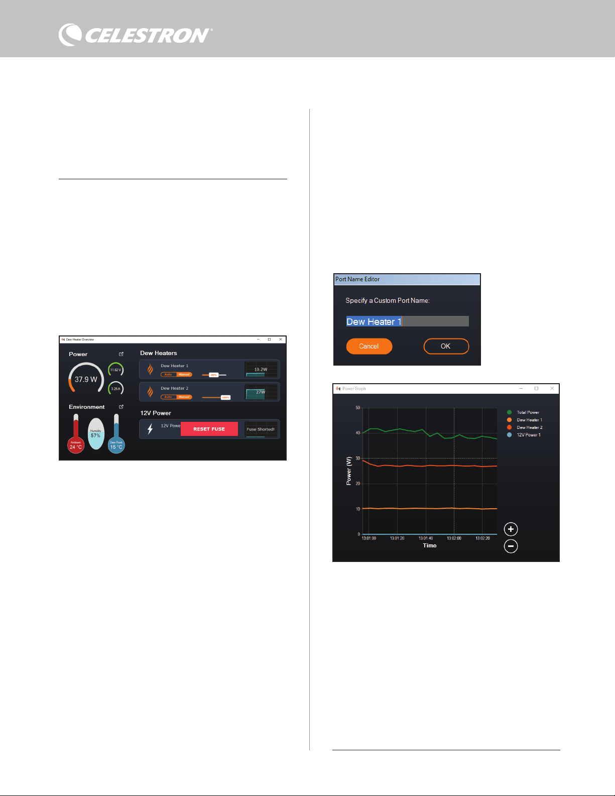
8 | DEUTSCH
Wenn Sie das Tauheizungssymbol auswählen, wird das
Tauheizungsmenü angezeigt. (Abbildung 13). Die erste Zeile im
Tauheizungsmenü zeigt die Gesamtleistungsaufnahme aller an die
Steuerung angeschlossenen Geräte an. Tippen Sie auf „Overview“
(Übersicht), um weitere Daten anzuzeigen.
ÜBERSICHT
Der Übersichtsbildschirm zeigt die Leistungsaufnahme für jeden
Anschluss der Steuerung an (Abbildung 14). Die Symbole neben den
derzeit verwendeten Anschlüssen wechseln zu Orange und zeigen
die Leistungsaufnahme über die Zeit in dem kleinen Diagramm rechts
an. In der oberen linken Ecke des Übersichtsbildschirms sehen Sie
die Gesamtleistung und die Stromaufnahme der Steuerung sowie
die Eingangsspannung der Stromquelle. Darunter sehen Sie die
Umgebungstemperatur und Luftfeuchtigkeit vom Umgebungssensor
sowie den berechneten Taupunkt.
Im Übersichtsmenü können Sie auch jeden Ausgangsanschluss
ein- oder abschalten, einschließlich der beiden Anschlüsse für die
Tauheizung und den Ausgangsstromanschluss. Wenn Sie sich aus
der Ferne in den PC einloggen, der mit der Steuerung verbunden
ist, können Sie Ihre Geräte hier aus der Ferne ein- und ausschalten.
Verwenden Sie für den Stromanschluss einfach die Schaltfläche ON/
angeschlossenen Tauheizung. Sobald Sie den gewünschten Wert
eingegeben haben, drücken Sie ENTER.
l Um einen Tauheizungsanschluss abzuschalten, wählen Sie
Manuelle Steuerung und stellen den Schieberegler auf 0 %.
- Wenn Sie den automatischen Modus wählen, müssen Sie
das „Schutzniveau“ einstellen. Dabei handelt es sich um
eine Zahl von 1 (niedrigstes Schutzniveau) bis 10 (höchstes
Schutzniveau), die angibt, wie aktiv die Steuerung bei der
Vermeidung von Tau ist. Ein höheres Schutzniveau benötigt mehr
Strom, bietet aber den höchsten Grad an Tauvermeidung bei
wechselnden Umgebungsbedingungen. Im Allgemeinen können
Sie eine niedrigere Schutzniveaueinstellung für wärmere und
trockenere und eine höhere Einstellung für kühlere und feuchtere
Beobachtungsorte verwenden. Verwenden Sie außerdem eine
höhere Schutzniveaueinstellung für größere Aperturen und eine
niedrigere Schutzniveaueinstellung, wenn Sie einen Tauschutz
verwenden oder es windig ist. Verwenden Sie den Schieberegler,
um das Schutzniveau einzustellen. Wenn Sie sich nicht sicher sind,
welche Schutzniveaueinstellung Sie verwenden sollen, versuchen
Sie es zunächst mit 5 (Standardeinstellung).
Sie können jeden Anschluss auf dem Übersichtsbildschirm
umbenennen, indem Sie auf den Namen des Anschlusses tippen. Das
Fenster Anschlussnamen-Editor wird angezeigt (Abbildung 16) und
Sie können den neuen Namen eingeben. Tippen Sie abschließend
auf die Schaltfläche OK und der neue Anschlussname angezeigt.
Dies hilft Ihnen, Ihre Steuerungen zu organisieren, da Sie jeden
Anschluss eines angeschlossenen Geräts umbenennen können. Sie
können Ihre Anschlüsse zum Beispiel in „8-Zoll-Tauheizmanschette“
oder „CGX-Montierung“ umbenennen.
LEISTUNGSDIAGRAMM
Abb. 15
Wenn die Leistung an einem Anschluss 84 W überschreitet, wird der Anschluss automatisch
abgeschaltet. Um ihn wieder zu aktivieren, verringern Sie die Last am betroffenen Anschluss
und tippen Sie dann auf das Feld „RESET FUSE“ (Sicherung zurücksetzen).
Abb. 16
Anschlussname-
Bearbeitungsfenster
OFF (Ein/Aus). Wählen Sie für die Tauheizungsanschlüsse die Option
„Manual“ (Manuell) und stellen Sie die Leistungsstufe auf Null.
Wie bereits erwähnt, werden die Anschlüsse der Steuerung
automatisch abgeschaltet, wenn an einem der Anschlüsse eine zu
hohe Last (mehr als 84 W) anliegt oder wenn die Gesamtlast der
Steuerung 120 W (10 A max. Strom) übersteigt. In diesem Fall
erscheint die Meldung „Fuse Blown“ (Sicherung durchgebrannt)
und im Übersichtsbildschirm wird neben dem/den betroffenen
Anschluss/Anschlüssen ein Feld „RESET FUSE“ (Sicherung
zurücksetzen) angezeigt (Abbildung 15). Um einen Anschluss erneut
zu aktivieren, nachdem er automatisch deaktiviert wurde, verringern
Sie nötigenfalls zunächst die Last am Anschluss. Tippen Sie dann
auf das Feld „RESET FUSE“ (Sicherung zurücksetzen), um die
Stromversorgung des Anschlusses wieder zu aktivieren.
HINWEIS: Wenn die Gesamtlast an der Steuerung 120 W (10 A
max. Strom) überschritten hat, müssen Sie alle Anschlüsse wieder
aktivieren.
Unter jedem Tauheizungsanschluss befinden sich Schaltflächen,
mit denen Sie vom automatischen „intelligenten“ zum manuellen
Steuermodus wechseln können:
– Wenn Sie den manuellen Modus wählen, müssen Sie die
gewünschte Leistungsstufe angeben. Dies ist eine Zahl zwischen 0
und 100 – der Prozentsatz der max. Leistung der an den Anschluss
Abb. 17
Leistungsdiagramm-Fenster
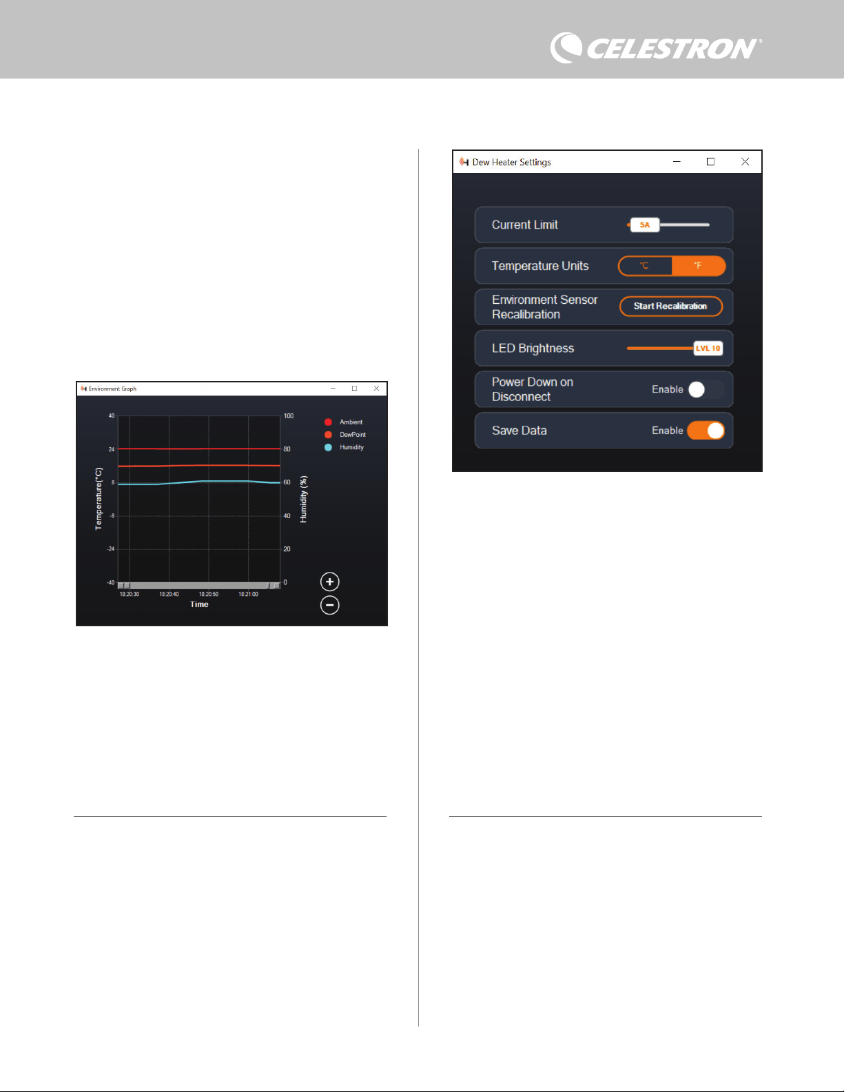
DEUTSCH | 9
Mit den Kreisen „+“ und „-“ unten rechts im Diagramm können Sie
in einen bestimmten Zeitbereich hineinzoomen, um mehr Details
anzuzeigen. Wenn Sie über ein Touchpad verfügen, können Sie zum
Zoomen die Finger auch zusammenziehen oder auseinanderschieben
bzw. das Scrollrad Ihrer Maus verwenden. Verwenden Sie den
Schieberegler, der unten im Diagramm angezeigt wird, um einen
bestimmten Zeitbereich zu suchen.
UMGEBUNGSDIAGRAMM
Wählen Sie „Environment Graph“ (Umgebungsdiagramm) im
Tauheizungsmenü aus, um das Umgebungsdiagramm-Fenster
aufzurufen (Abbildung 18). Sie können das Leistungsdiagramm
auch direkt vom Übersichtsbildschirm aus aufrufen, indem Sie auf
das Verknüpfungspfeil-Symbol neben dem Wort „Environment“
(Umgebung) links im Übersichtsbildschirm tippen. Dieses Diagramm
zeigt die Umgebungstemperatur, die Luftfeuchtigkeit und den
berechneten Taupunkt im Zeitverlauf an. Für die Lufttemperatur
und den Taupunkt wird die °C-Temperaturskala auf der linken
Seite des Diagramms verwendet. Für die Luftfeuchtigkeit wird die
%-Luftfeuchtigkeitsskala auf der rechten Seite des Diagramms
verwendet. Jede farbige Linie im Diagramm steht für einen anderen
Wert. Wenn Sie die Farbe für einen Wert ändern möchten, fahren
Abb. 18
Umgebungsdiagramm-Fenster
Abb. 19
Tauheizungs-Einstellfenster
Wählen Sie „Power Graph“ (Leistungsdiagramm) aus dem
Tauheizungsmenü, um das Leistungsdiagramm-Fenster aufzurufen
(Abbildung 17). Sie können das Leistungsdiagramm auch direkt
vom Übersichtsbildschirm aus aufrufen, indem Sie auf das
Pfeilsymbol neben dem Wort „Power“ (Leistung) oben links im
Übersichtsbildschirm tippen.
Das Leistungsdiagramm zeigt den Strombedarf aller Geräte
über die Zeit an, die an die Tauheizungsanschlüsse und den
Ausgangsstromanschluss der Steuerung angeschlossen sind. Jede
farbige Linie im Diagramm steht für einen anderen Anschluss. Wenn
Sie die Farbe für einen Anschluss ändern möchten, fahren Sie mit der
Maus über den Anschluss und tippen Sie mit der rechten Maustaste.
Sie können einen Anschluss im Diagramm ausblenden, indem Sie
auf den Kreis links neben dem Anschlussnamen tippen. Um die Linie
im Diagramm wieder zu aktivieren, tippen Sie einfach erneut auf den
Kreis.
Sie mit der Maus über ihn und tippen Sie mit der rechten Maustaste.
Sie können einen Wert im Diagramm ausblenden, indem Sie auf den
Kreis links neben dem Namen des Werts im Diagramm tippen. Um
die Linie im Diagramm wieder zu aktivieren, tippen Sie einfach erneut
auf den Kreis.
Mit den Kreisen „+“ und „-“ unten rechts im Diagramm können Sie
in einen bestimmten Zeitbereich hineinzoomen, um mehr Details
anzuzeigen. Wenn Sie über ein Touchpad verfügen, können Sie zum
Zoomen die Finger auch zusammenziehen oder auseinanderschieben
bzw. mit dem Scrollrad Ihrer Maus in Zeitbereiche hinein- und
herauszoomen. Verwenden Sie den Schieberegler, der unten im
Diagramm angezeigt wird, um einen bestimmten Zeitbereich zu
suchen.
Um die Temperatureinheiten von Grad Fahrenheit (Standard) in
Grad Celsius zu ändern, verwenden Sie die Auswahl „Settings“
(Einstellungen) im Tauheizungsmenü.
EINSTELLUNGEN
Über die Auswahl „Settings“ (Einstellungen) im Tauheizungsmenü
wird das Fenster Tauheizungs-Einstellungen aufgerufen (Abbildung
19).
– Stromgrenzwert
l Verwenden Sie den Schieberegler, um den max. Strom für die
von Ihnen verwendete Stromversorgung einzustellen. Wenn die
Stromaufnahme der Steuerung den eingestellten max. Strom
überschreitet, leuchtet die LED „Over Current“ (Überstrom)
auf der Brücke der Steuerung. In diesem Fall müssen Sie die
Stromaufnahme verringern, indem Sie die an die Steuerung
angeschlossenen Geräte herunterfahren oder abschalten.
Alternativ können Sie auch eine andere Stromversorgung
verwenden, die mehr Strom liefern kann. Stellen Sie in diesem
10 | DEUTSCH
Fall sicher, dass Sie den Stromgrenzwert entsprechend
anpassen.
– Temperatureinheiten
l Ändern Sie die Temperatureinheiten in CPWI mit den Tasten
°C und °F.
- Rekalibrierung des Umgebungssensors
l Verwenden Sie die Schaltfläche „Start Recalibration“
(Rekalibrierung starten), um den Umgebungssensor
neu zu kalibrieren. Dadurch wird der Sensor aufgeheizt,
um Feuchtigkeit, die sich auf ihm angesammelt hat, zu
verdampfen. Die Rekalibrierung trägt für die genauesten
Sensormesswerte bei. Es dauert etwa 10 Minuten, bis
sich der Sensor erwärmt und wieder abgekühlt hat. Wir
empfehlen, den Umgebungssensor regelmäßig neu zu
kalibrieren, vor allem, wenn der Sensor längere Zeit nicht
benutzt oder in feuchter Umgebung aufbewahrt wurde.
Dies trägt zu einem möglichst effizienten Strombedarf der
Tauheizung bei.
n Wenn Sie die Umgebungstemperatur oder die
Luftfeuchtigkeit während der Neukalibrierung überprüfen,
werden auf dem Display die zuletzt vor Beginn der
Neukalibrierung ermittelten Werte angezeigt.
– LED-Helligkeit
l Legen Sie die Helligkeit der LEDs an der Steuerung mit dem
Schieberegler fest. Eins ist die schwächste Einstellung und
zehn ist die hellste.
– Abschalten beim Trennen der Verbindung
l Sie können festlegen, dass alle angeschlossenen Geräte
ausgeschaltet werden, wenn Sie die Verbindung zwischen
Steuerung und CPWI trennen. Tippen Sie dazu auf die
Schaltfläche „Enable“ (Aktivieren). Wenn Sie CPWI
wieder anschließen, schalten sich alle Anschlüsse wieder
ein. Wenn Sie diese Funktion nicht aktivieren, fließt der
Strom wie gewohnt durch die Steuerung, wenn Sie die
Verbindung zu CPWI trennen.
– Daten speichern
l Mit dieser Funktion können Sie die Rohdaten der Steuerung in
das CSV-Format exportieren, das Sie in Microsoft Excel oder
Google Sheets öffnen können. Wenn Sie diese Option wählen,
finden Sie die gespeicherte .CSV-Datei in diesem Ordner auf
Ihrem PC: Dokumente\Celestron\CPWI
Um die Verbindung zur Intelligenten Tauheizungssteuerung 2x am
Abb. 20
Anwendungsabschaltfenster
Ende einer Beobachtungssitzung zu trennen, können Sie entweder
CPWI schließen, woraufhin das Fenster zum Herunterfahren der
Anwendung angezeigt wird (Abbildung 20) oder Sie können auf das
Symbol „Connection“ (Verbindung) in der oberen linken Ecke tippen
und „Disconnect“ (Trennen) wählen. Wenn Sie im Menü „Dew Heater
Settings“ (Tauheizungseinstellungen) die Option „Power Down on
Disconnect“ (Abschalten beim Trennen) gewählt haben, werden alle
mit der Steuerung verbundenen Geräte abgeschaltet. Andernfalls
fließt weiterhin Strom durch die Anschlüsse der Steuerung wie
gewohnt.
9. Technische Daten
Gewicht: 544 g.
Abmessungen: 14 cm x 11,5 cm x 8,25 cm
Gehäuse: Aluminium, lüftergekühlt, integrierte
Schwalbenschwanzklemmen und Stativgurt
Stromversorgungseingang: 12 VDC nominal, 13,8 VDC max.
Eingangsspannung, 10 A max. Eingangsstrom, 5,5-mm-/2,1-mm-
Hohlstecker-Gewindeanschluss (Spitze ist der Pluspol)
Stromausgangsanschluss: 12 VDC, 5,5-mm-/2,1-mm-
Hohlstecker-Gewindeanschluss (Spitze ist der Pluspol), 7 A max.
Ausgangsstrom
Tauheizungsausgänge: 2 x Cinchbuchsen, 12 VDC, 7 A max.
Ausgangsstrom für jeden Anschluss
Thermistor-Buchse: 2 x 2,5-mm-Audiobuchse, kompatibel mit
Celestron-Tauheizungsmanschetten und optionalem Celestron-
Thermistor
AUX-Anschlüsse: 2 x AUX-Anschlüsse, kompatibel mit Celestron-
Montierungen und anderen Celestron-Produkten
Umgebungssensor: Integriert, liefert Daten zu
Umgebungstemperatur und Luftfeuchtigkeit, kann für beste Leistung
neu kalibriert werden
Stromkreisschutz: intern rücksetzbare Sicherungen für jeden
Anschluss, Verpolungsschutz, Unterspannung, Überspannung,
Unterstrom, Überstrom
Firmware: Aktualisierbar über Firmware-Manager (CFM) Software
von Celestron
Stromkabel: 5,5-mm-/2,1-mm-Hohlstecker-Gewindeanschluss
(Spitze ist der Pluspol) an einem Ende, Zigarettenanzünderstecker
am anderen Ende, 10-A-Sicherung,16-Gauge-Draht

DEUTSCH | 11
Anhang A: Beispiele für die Ermittlung
der Stromversorgungsanforderungen
BEISPIELAUSRÜSTUNG NR. 1
– Celestron 20,3 cm Tauheizmanschette an Tauheizungsanschluss
Nr. 1 angeschlossen
l Max. Stromaufnahme der 20,3 cm Tauheizmanschette = 1,7 A
l Max. benötigte Leistung für 20,3 cm Tauheizmanschette = 12 V
x 1,7 A = 20,4 W
– Celestron Advanced VX EQ-Montierung an Stromanschluss Nr. 2
angeschlossen
l Max. Stromaufnahme für die Advanced VX EQ-Montierung beim
Schwenken mit höchster Geschwindigkeit = ca. 2,0 A
l Ma x . b en öti gte L eis tun g fü r Adv anc e d V X be im S chwe nke n mit m a x .
Geschwindigkeit = 12 V x 2,0 A = 24,0 W
In diesem Beispiel würde die max. Gesamtleistung der Steuerung
etwa 48 W betragen.
– Wenn Sie Zugang zu einer Netzsteckdose haben, wäre das
Celestron 5-A-Netzteil, das bis zu 60 W liefern kann, eine gute
Wahl für die Stromversorgung der Steuerung.
– Bei tragbaren Systemen kann der Celestron PowerTank Lithium Pro
bis zu 120 W Leistung (10 A max. Strom) liefern und würde daher
gut mit dieser Beispielausrüstung funktionieren.
l Die Akkukapazität des PowerTank Lithium Pro beträgt 158,7
Wattstunden. Die Steuerung verbraucht etwa 48 Watt pro
Stunde. Daher reicht der Akku in diesem Beispiel für mehr als
3 Stunden. Angenommen, Sie verwenden die automatische
intelligente Steuerung für die Tauheizmanschette. In diesem
Fall können Sie davon ausgehen, dass der Akku wesentlich
länger hält, da der Manschette wahrscheinlich nicht ständig
mit max. Leistung betrieben wird. Wenn Sie das Teleskop nicht
wiederholt mit der höchsten Geschwindigkeit schwenken,
ist die Stromaufnahme der Montierung viel geringer, was die
Lebensdauer des Akkus weiter verlängert.
BEISPIELAUSRÜSTUNG NR. 2
– Celestron 28 cm Tauheizmanschette an Tauheizungsanschluss Nr.
1 angeschlossen
l Max. Stromaufnahme der 28 cm Tauheizmanschette = 2,5 A
l Max. benötigte Leistung für 28 cm Tauheizmanschette = 12 V x
2,5 A = 30,0 W
– Heizband/Streifen eines anderen Herstellers für Leitrohr, das an
Tauheizungsanschluss Nr. 2 angeschlossen wurde
l Max. Stromaufnahme für Heizband/Streifen für Leitrohr = ca.
1,0 A
l Max. benötigte Leistung für Heizband/-streifen für Leitrohr = 12
V x 1,0 A = 12,0 W
– Celestron CGX EQ-Montierung an Stromanschluss Nr. 2
angeschlossen
l Max. Stromaufnahme der CGX EQ-Montierung beim
Schwenken mit höchster Geschwindigkeit = ca. 3,0 A
l Max. benötigte Leistung für die CGX EQ-Montierung beim
Schwenken mit max. Geschwindigkeit = 12 V x 3,0 A = 36,0 W
In diesem Beispiel würde die max. Gesamtleistung der Steuerung
etwa 78 W betragen.
– Wenn Sie Zugang zu einer Netzsteckdose haben, eignet sich
ein leistungsstarkes AC/DC-Netzteil für die Stromversorgung
der Steuerung. Das 5-A-Netzteil von Celestron würde nicht
funktionieren, da seine max. Leistung bei 60 W liegt.
l Wenn die Spannung des AC/DC-Netzteils variabel ist, stellen
Sie es auf 12 V ein, bevor Sie es an die Steuerung anschließen.
Denken Sie auch daran, dass die Stromeingangsbuchse eine
positive Spitze hat.
– Bei tragbaren Systemen kann der Celestron PowerTank Lithium
Pro bis zu 120 W Leistung (10 A max. Strom) liefern und würde
mit dieser Beispielausrüstung funktionieren. Allerdings reicht
die Leistungskapazität möglicherweise nicht für die gesamte
Beobachtungssitzung aus.
l Die Akkukapazität des PowerTank Lithium Pro beträgt 158,7
Wattstunden. Die Steuerung benötigt etwa 78 Watt pro Stunde.
Daher sollte der Akku in diesem Beispiel etwa 2 Stunden
lang halten. Angenommen, Sie verwenden die automatische
intelligente Steuerung für die Tauheizmanschette. In diesem
Fall können Sie davon ausgehen, dass der Akku wesentlich
länger hält, da der Manschette wahrscheinlich nicht ständig
mit max. Leistung betrieben wird. Wenn Sie das Teleskop nicht
wiederholt mit der höchsten Geschwindigkeit schwenken,
ist die Stromaufnahme der Montierung viel geringer, was die
Lebensdauer des Akkus weiter verlängert.
– Bei tragbaren Montierungen, die Sie die ganze Nacht betreiben
wollen, empfehlen wir einen 12-VDC-Schiffsakku oder einen
anderen tragbaren 12-VDC-Akku mit hoher Speicherkapazität.
l Wenn Sie vorhaben, die ganze Nacht (8 Stunden) mit dieser
Ausrüstung Bilder zu machen, benötigen Sie einen Schiffsakku
mit einer Kapazität von 78 W x 8 Stunden = 624 Wattstunden
(d. h. etwa 52 Amperestunden bei 12 VDC).
12 | DEUTSCH
FCC-ERKLÄRUNG: Dieses Gerät wurde getestet und entspricht den Grenzwerten für digitale Geräte der Klasse B in
Übereinstimmung mit Artikel 15 der FCC-Bestimmungen. Diese Grenzwerte sollen einen angemessenen Schutz gegen
schädliche Störungen in Wohngebieten bieten. Dieses Gerät erzeugt, verwendet Hochfrequenzenergie und kann diese
ausstrahlen und kann, wenn es nicht in Übereinstimmung mit den Anweisungen installiert und verwendet wird, Störungen
im Funkverkehr verursachen. Allerdings gibt es keine Garantie, dass bei einer bestimmten Installation keine Interferenzen
auftreten werden. Falls dieses Gerät abträgliche Interferenzen beim Funk- oder Fernsehempfang verursacht, was ermittelt
werden kann, indem man das Gerät ein- und ausschaltet, so sollte der Benutzer die Interferenz auf eine oder mehrere
der folgenden Arten beheben:
• Neuausrichtung oder Neuplatzierung der Empfangsantenne.
• Den Abstand zwischen dem Gerät und dem Empfänger vergrößern.
• Schließen Sie das Gerät an eine Steckdose an, die nicht an den Stromkreis des Empfängers angeschlossen ist.
• Wenden Sie sich an den Händler oder einen erfahrenen Radio-/Fernsehtechniker.
Dieses Gerät erfüllt Teil 15 der FCC-Richtlinien. Der Betrieb unterliegt den folgenden beiden Bedingungen: (1) Dieses Gerät
darf keine schädlichen Störungen erzeugen und (2) dieses Gerät muss Störungen von außen akzeptieren, dazu gehören
solche Störungen, die einen unerwünschten Betrieb verursachen.
Bitte beachten Sie, dass Änderungen oder Modifikationen an diesem Gerät, die nicht ausdrücklich vom Hersteller zuge-
lassen sind, zum Verlust der allgemeinen Betriebserlaubnis führen können.
Produktdesign und technische Daten können ohne vorherige Ankündigung geändert werden.
Dieses Produkt wurde für die Verwendung durch Personen von 14 Jahren und darüber entworfen und vorgesehen.
Hergestellt in China
©2022 Celestron. Celestron und Logo sind Marken von Celestron, LLC. • Alle Rechte
Vorbehalten. • Celestron.com • 2835 Columbia Street, Torrance, CA 90503 USA
celestron.com/pages/technical-support
10-22
celestron.com/pages/war ranty
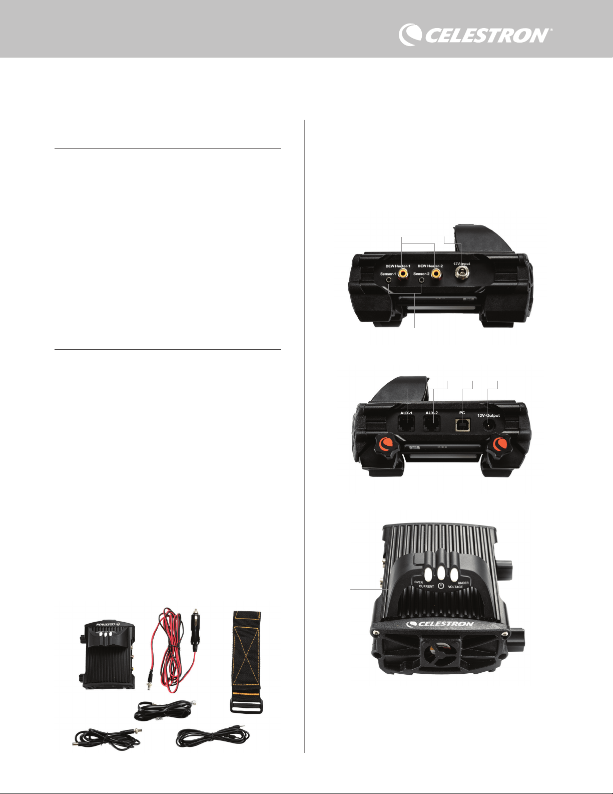
ITALIANO | 1
Congratulazioni per l’acquisto del comando smart per sistemi anticondensa
2x Celestron. Il comando permette un utilizzo intelligente ed efficiente di un
massimo di due sistemi riscaldanti anticondensa del telescopio nonché di
un dispositivo aggiuntivo da 12 V CC, consentendo allo stesso tempo di
gestire tutti i cavi presenti nella configurazione. Quando il comando viene
collegato ai sistemi riscaldanti anticondensa, un cavo serve a collegarli tutti
alla fonte di alimentazione, mentre un altro cavo collega la configurazione al
PC, se necessario.
Se non si desidera collegarsi a un PC, è sufficiente collegare i sistemi
riscaldanti anticondensa al comando e accenderlo. Il comando per sistema
anticondensa monitora automaticamente la temperatura ambiente e l’umidità
mediante l’apposito sensore ambiente. La porta del termistore monitora la
temperatura della lente e fornisce alimentazione sufficiente per evitare la
formazione di condensa. Se si utilizza un’alimentazione proveniente da una
batteria, il sistema “smart” riduce significativamente il consumo energetico
dei sistemi riscaldanti, prolungando la durata della batteria. Se si desidera
regolare manualmente le impostazioni o monitorare dati, collegarsi a un PC o
al comando manuale della montatura Celestron.
1. Elenco componenti
2. Panoramica comando
SOMMARIO
Fig 1 – Tutti i componenti in dotazione
Fare riferimento alla Figura 2 per una panoramica dei connettori
jack di ingresso, delle porte di uscita e di tutte le caratteristiche del
comando smart per sistemi anticondensa 2x.
In caso di componenti mancanti rispetto all’elenco componenti,
contattare il supporto tecnico Celestron all’indirizzo www.celestron.
com/pages/technical-support per assistenza.
1. Elenco componenti . . . . . . . . . . . . . . . . . . . . . . . . . . . . . . . . . . Pag.1
2. Panoramica comando . . . . . . . . . . . . . . . . . . . . . . . . . . . . . . . Pag.1
3. Come montare il comando in base alla
propria configurazione . . . . . . . . . . . . . . . . . . . . . . . . . . . . . Pag.3
4. Alimentazione del comando anticondensa . . . . . . . . . . . . . . Pag.4
5. Come collegare una montatura Celestron . . . . . . . . . . . . . . . Pag.5
6. Utilizzo del comando anticondensa
con un comando manuale Celestron . . . . . . . . . . . . . . . . . . . Pag.5
7. Collegamento a un PC. . . . . . . . . . . . . . . . . . . . . . . . . . . . . . . Pag.6
8. Utilizzo del comando anticondensa con il software CPWI . . . Pag.7
9. Specifiche . . . . . . . . . . . . . . . . . . . . . . . . . . . . . . . . . . . . . . . . . Pag.10
Appendice A:
Esempi su come determinare i requisiti di alimentazione . . . . Pag.11
COMANDO SMART E SISTEMI ANTICONDENSA 2X
MANUALE DI ISTRUZIONI
Modello n. 94035
ITALIANO
1. Porte sistema riscaldante anticondensa
2. Connettore jack ingresso alimentazione
3. Porte termistore
4. Porte AUX
5. Porta PC
6. Porta uscita alimentazione
7. Ponte
1. 2.
3.
4.
5.
6
Fig 2-1
Fig 2-2
Fig 2-3
2.
3.
1.
6
7.
5. 4.
1. Comando smart per sistemi anticondensa 2x
2. Cavo di alimentazione
3. Cavo aggiuntivo
4. Cavo di alimentazione montatura
5. Fascia gamba treppiede
6 Cavo termistore

2 | ITALIANO
COMANDO PER SISTEMA ANTICONDENSA
Il comando smart per sistemi anticondensa 2x fornisce un controllo
automatico intelligente per un massimo di due anelli o due fasce
riscaldanti anticondensa.
Se si utilizza il comando con un anello riscaldante anticondensa
Celestron, collegare il connettore jack di ingresso dell’alimentazione
dell’anello a una delle porte di uscita del comando utilizzando la
prolunga in dotazione con l’anello. Quindi, collegare il cavo del
termistore in dotazione al connettore jack del termistore dell’anello
e alla corrispondente porta del termistore sul comando (Figura 3). Il
termistore segnala la temperatura della lente del correttore Schmidt.
Il comando utilizza questi dati insieme alle informazioni provenienti
dal suo sensore ambiente integrato (ad es. temperatura ambiente e
umidità) per fornire all’anello una quantità di energia sufficiente tale
da prevenire la formazione di condensa. Se si utilizza l’alimentazione
di una batteria, nella maggior parte dei casi, questo sistema prolunga
notevolmente la durata della batteria. Una volta collegato l’anello a
una delle porte del comando anticondensa, inizierà a riscaldarsi (a
meno che la porta non sia stata disabilitata manualmente, il che verrà
trattato più avanti nel manuale).
Occorre un cavo per termistore aggiuntivo se si desidera utilizzare
il comando automatico intelligente con più di un anello riscaldante
anticondensa Celestron. Il cavo del termistore è un cavo audio
standard da 2,5 mm, reperibile presso gran parte dei venditori di
elettronica. Assicurarsi di sceglierne uno abbastanza lungo da
soddisfare le proprie necessità di configurazione.
Il sensore ambiente del comando è situato nel “ponte” del comando
stesso (Figura 2). Questa posizione protegge il sensore da eventuale
calore emanato dalla scocca, garantendo al contempo un buon flusso
d’aria. Un sensore ambiente integrato fornisce una configurazione più
semplice e ordinata senza sensori esterni penzolanti che possano
essere d’intralcio.
Di tanto in tanto occorre ricalibrare il sensore ambiente. La
ricalibratura riscalda il sensore in modo da fare evaporare eventuale
umidità accumulata, assicurando l’accuratezza dei dati relativi a
temperatura e umidità e un utilizzo ottimale dell’energia. Si consiglia
la ricalibratura prima del primo utilizzo e dopo lunghi periodi di
conservazione in condizioni umide. La procedura è semplice e verrà
trattata più avanti nel manuale.
Se non si desidera utilizzare il comando automatico intelligente, è
possibile impostare l’alimentazione per ciascuna porta del sistema
riscaldante anticondensa da 0% (spento) a 100% (piena potenza).
Questa opzione verrà trattata in maggiore dettaglio più avanti nel
manuale.
Nel caso di utilizzo di una fascia o di un nastro riscaldanti non a
marchio Celestron, questi dovranno avere una spina di tipo RCA
per essere collegata alle porte di uscita del comando anticondensa.
L’utente ha due opzioni per controllare fasce/nastri di terzi:
1. È possibile acquistare il termistore opzionale per comandi
anticondensa smart Celestron per fornire così un controllo
automatico e intelligente dell’alimentazione. Collegare la fascia
riscaldante al telescopio e collegarne la spina a una delle apposite
porte per sistemi riscaldanti anticondensa. Quindi sistemare
la punta del termistore sotto la fascia riscaldante in modo che
sia fissata (potrebbe volersi impiegare del nastro adesivo).
Collegare la spina del termistore al relativo connettore jack sul
comando anticondensa (Figura 4). Il termistore non è accurato
come il termistore integrato per anello riscaldante anticondensa
Celestron, che è a contatto diretto con la lente del correttore.
Consente comunque un controllo automatico e intelligente di
fasce/nastri riscaldanti.
2. In alternativa, è possibile impostare manualmente l’uscita
di alimentazione per ciascuna porta per sistemi riscaldanti
anticondensa da 0% a 100%, come menzionato in precedenza.
Ciascuna porta per sistemi riscaldanti anticondensa può fornire una
potenza massima di 84 W (corrente massima 7 A), il che è più che
sufficiente per la maggior parte dei sistemi riscaldanti anticondensa.
Nel caso un sistema riscaldante collegato consumi più di 84 W, la
porta si disattiva automaticamente per proteggere il circuito. Dopo
avere ridotto il carico è possibile riabilitare la porta; tale processo
verrà trattato più avanti nel manuale.
CONTROLLO DELL’ALIMENTAZIONE
Un’utile caratteristica del comando smart per sistemi anticondensa
2x è la possibilità di fornire un’alimentazione da 12 V CC a un
dispositivo esterno. Molti utenti scelgono di alimentare in questo
modo la montatura, consentendo di alimentare i sistemi riscaldanti
anticondensa e la montatura mediante un’unica fonte di alimentazione.
Per alimentare un dispositivo da 12 V CC utilizzare il cavo di
alimentazione per montatura in dotazione: si tratta del cavo con
connettori cilindrici da 12 V CC alle due estremità (Figura 1).
Collegare semplicemente l’ingresso di alimentazione del dispositivo
alla porta di uscita di alimentazione da 12 V CC sul comando. La
porta richiede un connettore cilindrico da 12 V CC con punta positiva
da 5,5 mm/2,1 mm. Sul connettore cilindrico ad un’estremità del
cavo di alimentazione per montatura è presente un dado. È possibile
avvitare il dado sul connettore jack di alimentazione delle montature
Celestron dotate di un connettore cilindrico filettato per ottenere un
Fig 3
Collegare un anello riscaldante anticondensa Celestron al comando anticondensa utilizzando
la prolunga in dotazione con l’anello e il cavo per termistore in dotazione con il comando
anticondensa.
Fig 4
Se si utilizza una fascia o un nastro riscaldante di un altro produttore, occorre il termistore
opzionale Celestron per comandi smart per sistemi anticondensa.
Termistore Celestron
Prolunga
Cavo termistore
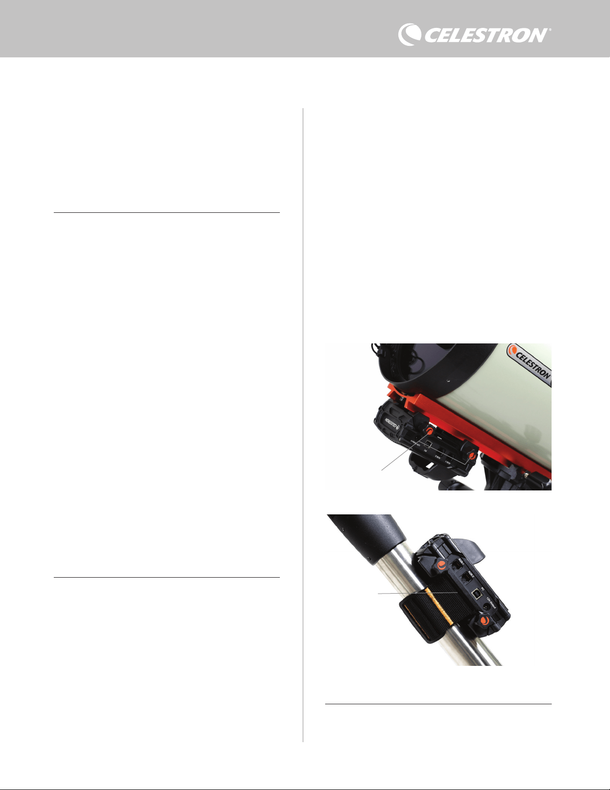
ITALIANO | 3
- Utilizzare il fermo a coda di rondine per collegare il comando
alla barra a coda di rondine di tipo CG-5/Vixen oppure CGE/
Losmandy. Se è presente una barra a coda di rondine sul tubo
ottico, questo è probabilmente il modo più semplice e comodo per
collegare il comando alla configurazione del telescopio. Allentare
semplicemente le manopole di bloccaggio del comando, sistemare
i fermi del comando sulla barra a coda di rondine, quindi serrare
saldamente le manopole di bloccaggio (Figura 5).
- Utilizzare la fascia per gamba del treppiede in dotazione per
collegare il comando a una delle gambe del treppiede. Inserire la
fascia attraverso le fessure alla base del comando, avvolgere la
fascia intorno a una delle gambe del treppiede, serrare la fascia
con la fibbia e fissare l’estremità della fascia a se stessa mediante
la chiusura in velcro (Figura 6).
- Se il vassoio portaccessori è abbastanza grande, è possibile
sistemare il comando su di esso. Se viene scelta questa opzione,
tenere presente che il comando non è fissato in posizione. Prestare
attenzione a evitare di strattonare con forza i cavi.
NOTA: NON SISTEMARE IL COMANDO A TERRA! Acqua e sporco
possono potenzialmente penetrare all’interno del comando e causare
problemi elettrici.
COME UTILIZZARE IL PONTE PER GESTIRE I DIVERSI CAVI
Il ponte situato sulla scocca ospita il sensore ambiente del comando
e lo isola dal calore irradiato per fornire dati relativi a temperatura
ambiente e umidità più accurati possibile. Il ponte è stato inoltre
progettato per agevolare la gestione dei cavi. È possibile fare passare
collegamento ottimale. L’alimentazione passa attraverso la porta non
appena viene collegato il dispositivo: non occorre attivare la porta (a
meno che la porta non sia stata disabilitata in precedenza, il che verrà
trattato più avanti nel manuale).
La porta di alimentazione può fornire una potenza massima di 84 W
(corrente massima 7 A). Nel caso un dispositivo collegato consumi
più di 84 W, la porta si disattiva automaticamente per proteggere il
circuito. Dopo avere ridotto il carico è possibile riabilitare la porta;
tale processo verrà trattato più avanti nel manuale.
SPIE LED DI STATO
Sul ponte sono presenti tre spie LED che indicano lo stato del
comando:
- La spia LED centrale indica se l’alimentazione sta arrivando al
comando.
- La spia LED “Over Current” (Sovracorrente) si illumina se la
corrente consumata è maggiore di quella fornita dalla fonte di
alimentazione. Se ciò accade scollegare o ridurre l’alimentazione
a uno dei dispositivi collegati al comando oppure impiegare una
fonte di alimentazione in grado di fornire una quantità maggiore
di corrente. Occorre impostare la quantità massima di corrente
consumata per l’alimentazione impiegata perché questa spia LED
funzioni correttamente (vedere più avanti nel manuale).
l Nel caso si verifichi un cortocircuito su uno dei dispositivi
collegati, la spia LED “Over Current” (Sovracorrente)
lampeggia e la porta interessata viene disattivata. Seguire le
istruzioni fornite più avanti nel manuale per riattivare la porta e
poterla così utilizzare nuovamente.
- La spia LED “Under Voltage” (Sottotensione) si illumina se la
potenza in ingresso verso il comando è inferiore a 11,0 V CC. Ciò
potrebbe verificarsi se la batteria che fornisce l’alimentazione è
quasi scarica. In questo caso, occorre utilizzare una diversa fonte
di alimentazione oppure ricaricare la batteria. La spia LED “Under
Voltage” (Sottotensione) protegge la batteria dallo scaricarsi
completamente, il che potrebbe portare a una riduzione della vita
utile della batteria.
l Se la tensione di ingresso della fonte di alimentazione
supera i 13,8 V, tutte le porte di uscita vengono disattivate
per proteggere il circuito e la spia LED “Under Voltage”
(Sottotensione) lampeggia. In tale circostanza occorre
sostituire la fonte di alimentazione con una che fornisca una
potenza inferiore a 13,8 V nonché riabilitare manualmente
tutte le porte di uscita secondo le istruzioni fornite nel
presente manuale.
Se, durante un’osservazione notturna, le spie LED risultano troppo
luminose, è possibile regolarne la luminosità. Come fare ciò verrà
spiegato più avanti nel manuale.
PROTEZIONE AGGIUNTIVA DEL CIRCUITO
In aggiunta agli avvisi forniti dalle spie LED di stato, il comando smart
per sistemi anticondensa 2x presenta altre funzioni di protezione del
circuito per garantire la sicurezza dell’apparecchiatura.
Se la potenza totale consumata dal comando supera i 120 W
(corrente massima 10 A), il comando si spegne automaticamente.
Ridurre il carico del comando e riabilitare manualmente le porte
seguendo le istruzioni riportate più avanti nel presente manuale.
Se si collega per errore la fonte di alimentazione di ingresso con la
polarità sbagliata, il comando non si accende per evitare danni al
circuito.
3. Come montare il comando in base alla
propria configurazione
Stabilire in che maniera di desidera collegare il comando alla
configurazione del proprio telescopio. Sono disponibili diverse
opzioni:
Fig 6
Fessura fascia
treppiede
Fig 5
Manopole di
bloccaggio

4 | ITALIANO
i cavi al di sotto del ponte per tenerli insieme e ordinati (Figura 7).
Basta semplicemente inserire l’estremità del cavo sotto il ponte e
tirarlo fino a quando è presente abbastanza gioco per collegare la
spina del cavo alla porta corrispondente del comando.
4. Alimentazione del comando
Occorre una fonte di alimentazione adatta da 12 V CC per il
comando smart per sistemi anticondensa 2x. La tipologia corretta di
alimentazione da 12 V CC dipende dall’apparecchiatura collegata al
comando. La potenza massima che può gestire il comando è 120 W
(corrente massima 10 A @ 12 V CC), ma per molti utilizzi è sufficiente
meno potenza. Quando si sceglie una fonte di alimentazione è
fondamentale determinare la quantità approssimativa di potenza
per la propria configurazione e quanta capacità della batteria sarà
necessaria per la sessione di osservazione.
Formule utili:
- Tensione (in Volt) x Corrente (in Amp) = Potenza (in Watt)
- Corrente (in Amp) x Tempo (in ore) = Corrente della batteria
necessaria (in Amp/ore)
- Potenza (in Watt) x Tempo (in ore) = Potenza della batteria
necessaria (in Watt/ore)
La tensione in ingresso massima per il connettore jack di ingresso
è 13,8 V CC. Assicurarsi che la tensione in uscita della propria
fonte di alimentazione non superi questo valore. Se viene fornita
un’alimentazione superiore a 13,8 V CC, tutte le porte di uscita
vengono automaticamente disabilitate per proteggere il circuito e
la spia LED di stato “Over Voltage” (Sovratensione) sul ponte della
scocca lampeggia.
Occorre scegliere tra le seguenti opzioni di alimentazione:
- In caso di configurazione portatile occorre una batteria da 12 V
CC. Sono compatibili sia la batteria Celestron PowerTanks Lithium
Pro sia la batteria Celestron PowerTank 17AH. Utilizzare il cavo di
alimentazione in dotazione e collegare la spina accendisigari alla
batteria e il connettore cilindrico filettato al comando (Figura 8).
NOTA: Se si utilizzano due sistemi riscaldanti anticondensa in
condizioni di forte umidità e si collega un dispositivo da 12 V CC,
il comando potrebbe funzionare vicino al proprio limite di potenza
massima di 120 W (corrente 10 A). In questo caso la batteria
PowerTank Lithium Pro e la batteria PowerTank 17Ah potrebbero
non avere abbastanza capacità per alimentare tale configurazione
per tutta la notte. Occorre una batteria con maggiore capacità.
- Se è possibile collegarsi a una presa di corrente CA, può
essere utilizzato un adattatore da CA a 12 V CC. Se la propria
configurazione richiede una potenza di 60 W o inferiore (corrente
5 A o inferiore), è possibile utilizzare l’adattatore CA Celestron
5 A. Per un collegamento ottimale, collegare il cavo di uscita
dell’adattatore al connettore jack di ingresso alimentazione del
comando anticondensa, serrare il connettore all’estremità del cavo
alla parte esterna del connettore jack, quindi collegare l’adattatore
alla presa di alimentazione CA (Figura 9).
AVVERTENZA: LA POTENZA MASSIMA ACCETTATA DAL
CONNETTORE JACK DI INGRESSO È 120W (CORRENTE
MASSIMA 10 A @ 12 V). Se viene collegata una fonte di
alimentazione capace di fornire più di 120 W al connettore jack
di ingresso alimentazione potrebbero verificarsi danni al cavo
di alimentazione del comando e al comando stesso. Se sono
necessari più di 120 W, si consiglia l’acquisto del Comando di
alimentazione smart per sistemi anticondensa 4x Celestron, il
quale è in grado di gestire fino a 240 W (corrente massima 20 A).
NOTA: Se la messa in funzione si avvicina alla corrente massima
di 10 A, si verifica un calo di tensione di circa 1 V dalla fonte di
alimentazione al comando dovuto al cavo di alimentazione. In
questo caso si consiglia di utilizzare una fonte di alimentazione
che fornisca poco più di 12 V (ma meno di 13,8 V).
Consultare l’Appendice A per una guida a diverse configurazioni di
alimentazione.
Una volta selezionata la fonte di alimentazione, occorre impostare
l’apporto massimo di corrente da tale fonte mediante il comando
manuale Celestron o il software CPWI (trattato più avanti nel presente
manuale). Quindi, nel caso il comando anticondensa consumi più
corrente del valore massimo specificato, la spia LED “Over Current”
(Sovracorrente) si accende. Per impostazione predefinita l’apporto
massimo di corrente è 2,0 A, il che è un valore relativamente basso.
Pertanto, se non è stato impostato l’apporto massimo di corrente
Fig 9
Se, per la propria configurazione, occorrono 5 A (60 W) di potenza o meno e si ha
accesso a una presa di corrente CA, è possibile utilizzare l’adattatore CA 5 A Celestron
per alimentare il comando. Utilizzare il connettore cilindrico filettato per un collegamento
ottimale.
Connettore cilindrico filettato
Adattatore CA 5 A
Fig 8
È possibile utilizzare il cavo di alimentazione in dotazione per collegare una batteria al
comando. Utilizzare il connettore cilindrico filettato per un collegamento ottimale.
PowerTank Lithium Pro
Cavo di alimentazione
Connettore cilindrico filettato
Il ponte della scocca è progettato per agevolare la gestione dei cavi.
Fig 7
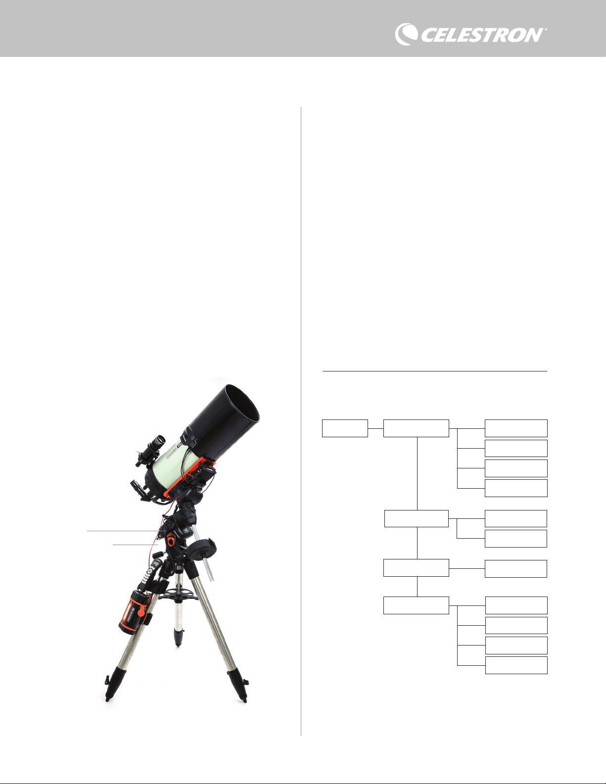
ITALIANO | 5
per la fonte di alimentazione, la spia LED potrebbe accendersi
prematuramente.
Quando si collega l’alimentazione al connettore jack di ingresso
alimentazione, il comando anticondensa è acceso. L’alimentazione
scorre attraverso le porte.
5. Come collegare una montatura
Celestron
Se si utilizza il comando smart per sistemi anticondensa 2x con
una montatura Celestron, è possibile collegarlo alla montatura per
modificare impostazioni e dati di monitoraggio mediante il comando
manuale della montatura. Questa rappresenta un’ottima opzione nel
caso di configurazioni prive di un collegamento a un PC.
Prima di utilizzare il comando manuale del telescopio con il comando
smart per sistemi anticondensa 2x potrebbe essere necessario
aggiornare il firmware del comando manuale. Per il comando
manuale NexStar+, è necessaria la versione del firmware 5.33.1333
o superiore. Per il comando manuale StarSense, è necessaria la
versione del firmware 1.22.21333 o superiore. È possibile verificare
il numero della versione del firmware premendo il tasto MENU e
utilizzando i tasti di scorrimento e INVIO per andare su Comando
manuale>Ottieni informazioni versione. Utilizzare il software
Celestron Firmware Manager (CFM) per aggiornare il firmware
se necessario. L’ultima versione è disponibile qui: https://www.
celestron.com/pages/drivers-and-software
Per utilizzare il comando manuale NexStar+ o StarSense collegare
il cavo AUX in dotazione a una porta AUX sulla montatura Celestron
e a una porta AUX sul comando smart per sistemi anticondensa
2x. Quindi, collegare il comando manuale della montatura alla
montatura come di consueto. In alternativa, è possibile collegare il
comando manuale direttamente a una delle porte AUX del comando
anticondensa. È inoltre possibile utilizzare il cavo di alimentazione
della montatura in dotazione per alimentare la montatura dalla porta
di uscita dell’alimentazione (Figura 10).
NOTA: L’alimentazione non passa attraverso le porte AUX a meno
che la montatura Celestron sia collegata a una delle porte AUX e
accesa. Se non è collegata una montatura Celestron, il comando
manuale collegato direttamente a una delle porte AUX non viene
alimentato.
6. Utilizzo del comando anticondensa con
un comando manuale Celestron
Una volta collegato, è possibile modificare impostazioni e dati di
monitoraggio mediante il comando manuale NexStar+ o StarSense.
Per fare ciò, accendere la montatura, premere il tasto MENU sul
comando manuale, navigare fino al menu del comando anticondensa
utilizzando i tasti di scorrimento e premere INVIO. Quindi, utilizzare i
tasti di scorrimento per visualizzare le opzioni del menu del comando
anticondensa, quindi premere INVIO per selezionare.
La Figura 11 mostra la struttura del menu del comando anticondensa.
NOTA: Se si utilizza il comando manuale StarSense, occorre
utilizzare i tasti di scorrimento per visualizzare il testo intero per
alcune funzioni del menu.
POTENZA IN INGRESSO
Selezionare questa opzione per monitorare la potenza consumata
dai dispositivi collegati al comando anticondensa. È inoltre possibile
Dew Heater Input Power
Power Status
Voltage Status
Current Status
Current Limit
Dew Heater #1
Dew Heater #2
Power #1
Ambient Temp
Humidity
Dew Point
Recalibration
Dew Heater Ports
Power Ports
Environment
Struttura menu comando manuale del sistema riscaldante anticondensa
Fig 11
Fig 10
Il cavo AUX in dotazione consente la comunicazione tra montatura e comando. È inoltre
possibile utilizzare il cavo di alimentazione della montatura in dotazione per alimentare la
montatura dalla porta di uscita dell’alimentazione.
Cavo AUX
Cavo di alimentazione
montatura
verificare la corrente in ingresso dalla fonte di alimentazione
e impostare l’apporto massimo di corrente. Utilizzare i tasti di

6 | ITALIANO
scorrimento sul comando manuale per scegliere tra le seguenti
opzioni, quindi premere INVIO per selezionare.
l Stato alimentazione – Mostra la potenza consumata dai dispositivi
collegati al comando anticondensa.
l Stato tensione – Mostra la tensione fornita dalla fonte di
alimentazione in ingresso.
l Stato corrente - Mostra la corrente utilizzata dai dispositivi collegati
al comando anticondensa.
l Limite corrente – Questo menu consente di impostare la corrente
massima per la fonte di alimentazione. Quando la corrente
consumata dai dispositivi collegati supera questo limite, la spia
LED “Over Current” (Sovracorrente) sul ponte del comando
anticondensa si illumina. Premere INVIO per impostare il limite
della corrente da 1,0 A a 10,0 A. Al termine, premere INVIO.
NOTA: Se viene superato il limite della corrente e la spia LED
“Over Current” (Sovracorrente) si accende, occorre scollegare un
dispositivo dal comando anticondensa oppure utilizzare un’altra
fonte di alimentazione che fornisca una quantità maggiore di
corrente. Se si utilizza un’altra fonte di alimentazione, assicurarsi
di modificare il limite della corrente.
PORTE PER SISTEMA RISCALDANTE ANTICONDENSA
Questa opzione mostra la potenza consumata da ciascuna
porta per sistema riscaldante anticondensa. Se non si desidera
utilizzare il comando automatico intelligente per i sistemi riscaldanti
anticondensa, questa opzione consente di impostare manualmente
l’uscita di alimentazione per ciascuna porta.
Dopo avere selezionato Porte per sistema riscaldante anticondensa
dal menu, è possibile scorrere fino alle due porte. Per ciascuna
porta del sistema riscaldante, lo schermo LCD sul comando
manuale mostra se la porta è in modalità Manuale o Automatica
nonché la potenza rilevata sulla porta in quel momento.
Per passare dalla Modalità automatica alla Modalità manuale,
selezionare la porta mediante i tasti di scorrimento, quindi premere
INVIO. Quindi utilizzare i tasti di scorrimento per scegliere tra
Modalità manuale e Modalità automatica, quindi premere INVIO.
- Se si sceglie la Modalità manuale, occorre specificare il Livello
di potenza desiderato. Questo deve essere un numero compreso
tra 0 e 100 e rappresenta la percentuale di potenza massima
che fluisce verso il sistema riscaldante anticondensa collegato
alla porta. Una volta inserito il valore desiderato, premere INVIO.
Per disabilitare una porta del sistema riscaldante anticondensa
selezionare l’apposita porta, passare a Modalità manuale e
impostare il Livello di potenza a 0%.
- Se si sceglie la Modalità automatica, occorre specificare il Livello
di aggressione. Questo deve essere un numero compreso tra 1
(aggressione minima) e 10 (aggressione massima) che indica
quanto è attivo il comando anticondensa smart nella prevenzione
della condensa. L’impostazione di un livello di aggressione
maggiore impiegherà più potenza, ma fornirà maggiore
prevenzione dalla condensa in caso di mutamento delle condizioni
ambientali. In generale, è possibile scegliere l’impostazione di un
livello di aggressione inferiore per siti di osservazioni più caldi e
asciutti e un’impostazione maggiore per siti di osservazione più
freschi e umidi. Inoltre, utilizzare l’impostazione di un livello di
aggressione maggiore per aperture maggiori e un livello inferiore
in caso di utilizzo di uno scudo anti-rugiada o se l’ambiente è
ventoso. Nel caso di incertezza sul livello di aggressione da
usare, provare inizialmente 5 (impostazione predefinita). Una volta
impostato il livello di aggressione, premere INVIO.
PORTA DI ALIMENTAZIONE
Questa opzione consente di monitorare l’uscita di alimentazione da
12 V CC per un dispositivo collegato alla porta di alimentazione.
Se un dispositivo è collegato alla porta e viene selezionato “Porta
di alimentazione” dal menu del sistema riscaldante anticondensa,
lo schermo LCD mostra l’apporto di potenza. Per disabilitare
l’alimentazione a una porta per spegnere il dispositivo collegato,
premere INVIO per la porta selezionata. Lo schermo LCD mostra
il messaggio “Disabilitare porta?”. Per procedere, premere INVIO.
Se non si desidera disabilitare l’alimentazione, premere INDIETRO.
Per riattivare l’alimentazione alla porta e accendere nuovamente il
dispositivo collegato, premere nuovamente INVIO.
AMBIENTE
Questa opzione consente di visualizzare i dati provenienti dal sensore
ambiente. Qui è inoltre dove è possibile ricalibrare il sensore per
prestazioni ottimali. Utilizzare i tasti di scorrimento sul comando
manuale per scegliere tra le seguenti opzioni, quindi premere INVIO
per selezionare.
l Temperatura ambiente – Mostra la temperatura dell’aria
nell’ambiente.
l Umidità – Mostra l’umidità relativa.
l Punto di rugiada – Questo valore viene calcolato in tempo
reale utilizzando i dati su temperatura ambiente e umidità. Se la
temperatura della lente scende al di sotto del numero visualizzato,
si formerà della condensa sulla sua superficie.
l Ricalibratura – Per avviare la ricalibratura del sensore ambiente,
selezionare questa opzione e premere INVIO. Il sensore si riscalda
per fare evaporare l’umidità accumulata su di esso, fornendo in tal
modo una lettura quanto più accurata possibile. La ricalibratura
richiede circa 10 minuti dalla pressione del tasto INVIO fino a
quando il sensore si è raffreddato nuovamente alla temperatura
ambiente. Si consiglia di ricalibrare periodicamente il sensore
ambiente, specialmente se il sensore non è stato utilizzato per
diverso tempo oppure se è stato conservato in condizioni di
umidità.
n Se viene controllata la temperatura ambiente o l’umidità
durante la ricalibratura, lo schermo mostra i valori rilevati per
ultimi prima dell’inizio della calibratura.
RIABILITAZIONE DI UNA PORTA DISABILITATA
Come discusso in precedenza, le porte del comando anticondensa
vengono disabilitate automaticamente se una delle porte consuma
più di 84 W (corrente massima 7 A) oppure se il carico totale sul
comando supera 120 W (corrente massima 10 A). Per riabilitare
una porta dopo che è stata disabilitata automaticamente, procedere
come segue.
l Innanzitutto, ridurre il carico sul comando anticondensa.
l Per selezionare la porta disabilitata, premere MENU, scorrere
fino a “Sistema riscaldante anticondensa”, quindi premere INVIO.
Quindi scorrere su “Porta sistema riscaldante anticondensa”
oppure “Porta di alimentazione” e premere INVIO.
l Lo schermo LCD mostra il messaggio “Ripristinare fusibile?”
Premere INVIO per riabilitare la porta.
NOTA: Se il carico totale del comando anticondensa supera 120 W
(corrente massima 10 A), occorre riabilitare tutte le porte.
7. Connessione a un PC
Per alcuni tipi di configurazione risulta più comodo collegare il
comando smart per sistemi anticondensa 2x a un PC per regolare le
impostazioni e i dati di monitoraggio. Ciò è ancora più valido nel caso si
utilizzi già un PC per controllare la montatura o eventuali termocamere
o videocamere guida.
Per un collegamento cablato occorre un cavo USB da tipo A a tipo B
(non in dotazione). Collegare alla porta PC del comando anticondensa
e a una porta USB del PC. Una volta alimentato il comando
anticondensa, il computer dovrebbe riconoscerlo.
Se si utilizza una montatura computerizzata Celestron, è possibile
connettersi alla montatura e comandarla attraverso il comando smart
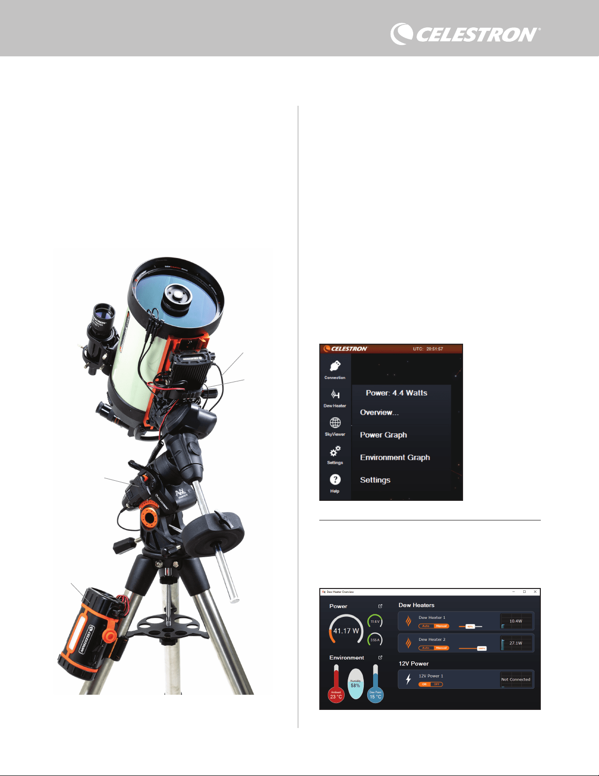
ITALIANO | 7
8. Utilizzo del comando anticondensa con
il software CPWI
Se si sta già controllando il telescopio o la videocamera da un
computer, sarà ancora più entusiasmante controllare il comando
smart per sistemi anticondensa 2x mediante il nostro software
gratuito CPWI Celestron. Per scaricare l’ultima versione visitare:
https://www.celestron.com/pages/celestron-pwi-telescope-control-
software
Installare il software e aprire CPWI. Selezionare “Avvio” quando
appare la finestra iniziale. Quindi, fare clic sull’icona “Connessione”
nell’angolo in alto a sinistra dello schermo. Se si sta utilizzando
un collegamento via cavo, selezionare “USB montatura”. Se
si sta utilizzando il modulo Wi-Fi SkyPortal, fare clic sull’icona
“Connessione”, quindi selezionare “WiFi”.
Il software CPWI dovrebbe rilevare e connettersi al comando
anticondensa. Una volta effettuato il collegamento, l’icona del sistema
riscaldante anticondensa dovrebbe apparire nel menu di scelta sulla
sinistra dello schermo.
Selezionare l’icona del sistema riscaldante anticondensa per
mostrare il relativo menu (Figura 13). La prima riga del menu del
sistema riscaldante anticondensa indica la potenza totale consumata
da tutti i dispositivi collegati al comando anticondensa. Per accedere
a ulteriori dati, fare clic su Panoramica.
PANORAMICA
La schermata Panoramica mostra la potenza consumata da ciascuna
porta del comando anticondensa (Figura 14). L’icona vicino a
ciascuna porta attualmente in uso diventa arancione con un piccolo
grafico a destra che indica la potenza consumata. Nell’angolo in
alto a sinistra della schermata Panoramica è possibile visualizzare
per sistemi anticondensa mediante il software per PC gratuito CPWI.
Per fare ciò utilizzare il cavo AUX in dotazione per collegare una delle
porte AUX del comando a una delle porte AUX della montatura.
Per collegare un PC al comando anticondensa tramite wireless
utilizzando il modulo Wi-Fi SkyPortal opzionale, occorre una montatura
Celestron e il modulo Wi-Fi (venduti separatamente). Collegare il
modulo Wi-Fi alla porta AUX della montatura. Collegare un’altra porta
AUX sulla montatura a una delle porte AUX del comando anticondensa
mediante il cavo AUX in dotazione. È inoltre possibile utilizzare il cavo di
alimentazione della montatura in dotazione per alimentare la montatura
da una delle porte di uscita dell’alimentazione (Figura 12). Una volta
collegati tutti i cavi, accendere la montatura.
NOTA: Se la montatura presenta esclusivamente una porta AUX,
occorre acquistare il separatore di porte AUX opzionale. Ciò trasforma
la porta AUX della montatura in due porte AUX.
Fig 13
Menu sistema riscaldante
anticondensa CPWI
Fig 14
Schermata panoramica
Fig 12
Se si utilizza una montatura Celestron con il Modulo Wi-Fi SkyPortal, è possibile collegarsi
al comando via Wi-Fi attraverso la montatura mediante il cavo AUX in dotazione. È inoltre
possibile utilizzare il cavo di alimentazione della montatura in dotazione per alimentare la
montatura dalla porta di uscita dell’alimentazione.
Cavo di alimentazione
montatura
Modulo Wi-Fi SkyPortal
PowerTank Lithium Pro
Cavo AUX
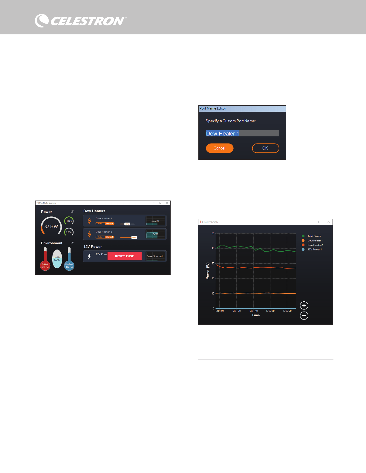
8 | ITALIANO
la potenza e la corrente totali consumate dal comando anticondensa
e la tensione in ingresso della fonte di alimentazione. Al di sotto di
tale dato è possibile visualizzare i dati relativi a temperatura ambiente
e umidità provenienti dal sensore ambiente e il punto di rugiada
calcolato.
Il menu Panoramica è inoltre dove è possibile abilitare o disabilitare
ciascuna porta di uscita, comprese le due porte del sistema
riscaldante anticondensa e la porta di uscita dell’alimentazione. Se
ci si collega da remoto al PC connesso al comando anticondensa, è
possibile accendere e spegnere i dispositivi da remoto. Per la porta
di alimentazione, utilizzare semplicemente il tasto ON/OFF. Per le
porte del sistema riscaldante anticondensa selezionare “Manuale” e
impostare il livello di potenza a zero.
Come discusso in precedenza, il comando anticondensa disabilita
automaticamente le porte se è presente un carico eccessivo su una
delle porte (più di 84 W) oppure se il carico totale sul comando
supera 120 W (corrente massima 10 A). Se ciò accade, appare
una notifica di fusibile bruciato nonché un pulsante “RIPRISTINA
FUSIBILE” vicino alle porte interessate nella schermata Panoramica
(Figura 15). Per riabilitare una porta dopo che è stata disabilitata
automaticamente, ridurre innanzitutto il carico sulla porta come
necessario. Quindi, fare clic sul pulsante “RIPRISTINA FUSIBILE”
per riabilitare l’alimentazione sulla porta.
maggiore per aperture maggiori e un livello inferiore in caso
di utilizzo di uno scudo anti-rugiada o se l’ambiente è ventoso.
Utilizzare il cursore per impostare il livello di aggressione. Nel caso
di incertezza sul livello di aggressione da usare, provare inizialmente
5 (impostazione predefinita).
È possibile rinominare ciascuna porta presente nella schermata
Panoramica facendo clic sul nome della porta. Appare la finestra
di Modifica nome porta (Figura 16) ed è possibile digitare il nuovo
nome. Al termine fare clic sul pulsante OK; quindi apparirà il nuovo
nome della porta. Ciò consente di mantenere in ordine tutti i
comandi poiché è possibile rinominare ciascuna porta del dispositivo
collegato. Per esempio, è possibile rinominare la porta “Anello
riscaldante anticondensa 8 pollici” o “Montatura CGX”.
GRAFICO POTENZA
Selezionare “Grafico potenza” dal menu del sistema riscaldante
anticondensa per far apparire la relativa finestra (Figura 17). È inoltre
possibile accedere al Grafico potenza dalla schermata Panoramica
facendo clic sulla freccetta del collegamento rapido a fianco alla
parola “Alimentazione” nell’angolo in alto a sinistra della schermata
Panoramica.
Il Grafico della potenza mostra il consumo energetico nel tempo
per tutti i dispositivi collegati alle porte del sistema riscaldante
anticondensa e alla porta di uscita alimentazione. Ciascuna linea
colorata nel grafico rappresenta una diversa porta. Se si desidera
modificare il colore di una porta, spostare il cursore sulla porta
desiderata e fare clic con il tasto destro.
È possibile nascondere una porta dal grafico facendo clic sul cerchio
a sinistra del nome della porta. Per riabilitare la relativa linea nel
Fig 17
Finestra Grafico potenza
Fig 15
Se la potenza su una porta supera 84 W, la porta si disattiva automaticamente. Per
riabilitarla, ridurre il carico sulla porta interessata, quindi fare clic sul pulsante RIPRISTINA
FUSIBILE.
Fig 16
Finestra Modifica nome porta
NOTA: Se il carico totale del comando anticondensa supera 120 W
(corrente massima 10 A), occorre riabilitare tutte le porte.
Sotto ciascuna porta del sistema riscaldante anticondensa sono
presenti pulsanti per passare dalla Modalità di controllo automatica
intelligente alla Modalità di controllo manuale:
- Se si sceglie la Modalità manuale, occorre specificare il Livello di
potenza desiderato. Questo deve essere un numero compreso tra 0
e 100 e rappresenta la percentuale di potenza massima che fluisce
verso il sistema riscaldante anticondensa collegato alla porta. Una
volta inserito il valore desiderato, premere INVIO.
l Per disabilitare una porta del sistema riscaldante anticondensa,
selezionare Controllo manuale e impostare il cursore su 0%.
- Se si sceglie la Modalità automatica, occorre specificare il Livello
di aggressione. Questo deve essere un numero compreso tra 1
(aggressione minima) e 10 (aggressione massima) che indica
quanto è attivo il comando anticondensa nella prevenzione della
condensa. L’impostazione di un livello di aggressione maggiore
impiegherà più potenza, ma fornirà maggiore prevenzione della
condensa in caso di mutamento delle condizioni ambientali. In
generale, è possibile scegliere l’impostazione di un livello di
aggressione inferiore per siti di osservazioni più caldi e asciutti
e un’impostazione maggiore per siti di osservazione più freschi e
umidi. Inoltre, utilizzare l’impostazione di un livello di aggressione

ITALIANO | 9
dell’aria e il punto di rugiada sono misurati nella scala della temperatura
in °C a sinistra del grafico. L’umidità è misurata dalla relativa scala in %
a destra del grafico. Ciascuna linea colorata nel grafico rappresenta
un diverso valore. Se si desidera modificare il colore di un determinato
valore, spostare il cursore su di esso e fare clic con il tasto destro.
È possibile nascondere un valore dal grafico facendo clic sul cerchio
a sinistra del nome del valore sul grafico. Per riabilitare la relativa linea
nel grafico, basta fare nuovamente clic sul cerchio.
Per ingrandire una determinata porzione di tempo nel grafico per
accedere a maggiori dettagli, utilizzare i cerchi “+” e “-” nell’angolo
inferiore destro del grafico. Se si utilizza un touchscreen, è inoltre
possibile avvicinare le dita per ingrandire oppure utilizzare la rotellina
del mouse per ingrandire e ridurre l’ingrandimento delle porzioni di
tempo. Utilizzare il cursore che appare sulla parte inferiore del grafico
per trovare una determinata porzione di tempo.
Per modificare l’unità di misura da gradi Fahrenheit (impostazione
predefinita) a gradi Celsius, utilizzare l’opzione “Impostazioni” dal
menu del sistema riscaldante anticondensa.
IMPOSTAZIONI
L’opzione “Impostazioni” del menu del sistema riscaldante
anticondensa apre la relativa finestra Impostazioni (Figura 19).
- Limite corrente
Fig 18
Finestra Grafico ambiente
Fig 19
Finestra Impostazioni sistema riscaldante anticondensa
grafico, basta fare nuovamente clic sul cerchio.
Per ingrandire una determinata porzione di tempo nel grafico per
accedere a maggiori dettagli, utilizzare i cerchi “+” e “-” nell’angolo
inferiore destro del grafico. Se si utilizza un touchscreen, è inoltre
possibile avvicinare le dita per ingrandire oppure utilizzare la rotellina
del mouse per ingrandire e ridurre l’ingrandimento. Utilizzare il
cursore che appare sulla parte inferiore del grafico per trovare una
determinata porzione di tempo.
GRAFICO AMBIENTE
Selezionare “Grafico ambiente” dal menu del sistema riscaldante
anticondensa per far apparire la relativa finestra (Figura 18). È inoltre
possibile accedere al Grafico ambiente dalla schermata Panoramica
facendo clic sulla freccetta del collegamento rapido a fianco alla parola
“Ambiente” nell’angolo in alto a sinistra della schermata Panoramica.
Questo grafico mostra la temperatura dell’aria dell’ambiente, l’umidità
e il punto di rugiada calcolato in un dato lasso di tempo. La temperatura
l Utilizzare il cursore per impostare la corrente massima per la fonte
di alimentazione utilizzata. Se l’apporto di potenza del comando
anticondensa supera la corrente massima impostata, la spia
LED “Over Current” (Sovracorrente) sul ponte della scocca
del comando anticondensa si accende. Se ciò accade occorre
ridurre la potenza spegnendo i dispositivi collegati al comando
anticondensa. In alternativa è possibile utilizzare una diversa
fonte di alimentazione capace di fornire una quantità maggiore di
corrente. In questo caso assicurarsi di regolare di conseguenza
il limite della corrente.
- Unità temperatura
l Per modificare le unità della temperatura nel software CPWI
mediante i pulsanti °C e °F.
- Ricalibratura sensore ambiente
l Utilizzare il pulsante “Avvio ricalibratura” per ricalibrare il sensore
ambiente. Questo riscalda il sensore per fare evaporare l’umidità
accumulata su di esso. La ricalibratura serve a fornire letture
più accurate da parte del sensore. Occorrono circa 10 minuti
perché il sensore si riscaldi e successivamente si raffreddi.
Si consiglia di ricalibrare periodicamente il sensore ambiente,
specialmente se il sensore non è stato utilizzato per diverso
tempo oppure se è stato conservato in condizioni di umidità.
Questo consente un utilizzo il più efficiente possibile della
potenza dei sistemi di riscaldamento anticondensa.
n Se viene controllata la temperatura ambiente o l’umidità
durante la ricalibratura, lo schermo mostra i valori rilevati per
ultimi prima dell’inizio della calibratura.
- Luminosità LED
l Impostare la luminosità delle spie LED sul comando
anticondensa tramite il cursore. Uno imposta la luminosità
minima, mentre dieci imposta la luminosità massima.
- Spegnimento alla disconnessione
l È possibile scegliere di spegnere tutti i dispositivi collegati
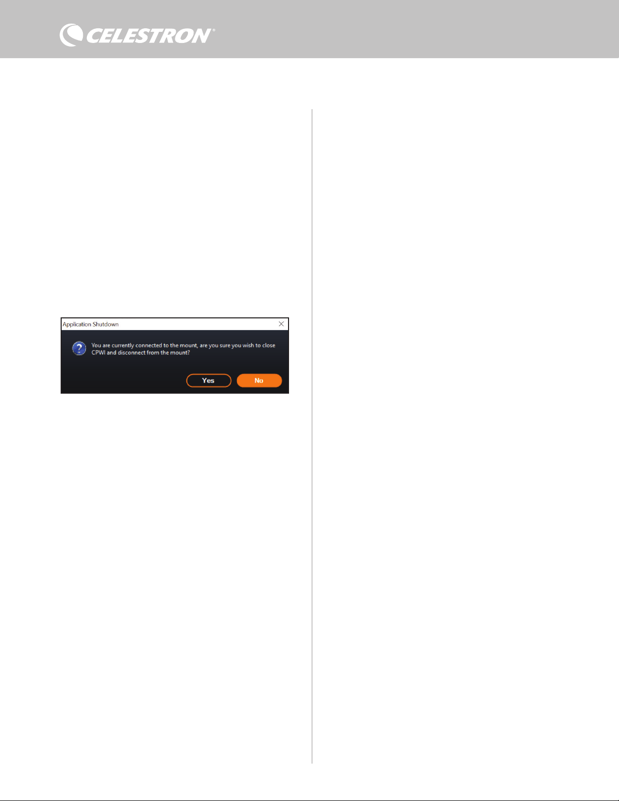
10 | ITALIANO
quando si scollega il comando anticondensa dal CPWI. Per fare
ciò, fare clic sul pulsante Abilita. Quando si ricollega il CPWI,
tutte le porte vengono riabilitate. Se questa funzione non viene
abilitata, una volta scollegato il CPWI, l’alimentazione continua a
fluire verso il comando anticondensa.
- Salva dati
l Questa funzione consente di esportare dati grezzi dal comando
anticondensa in formato .CSV, che può essere aperto con
Microsoft Excel oppure Google Sheets. Se questa opzione viene
selezionata, il file .CSV viene salvato nella seguente cartella sul
PC: Documents\Celestron\CPWI
Per scollegarsi dal Comando smart per sistemi anticondensa 2x al
termine di una sessione di osservazione, è possibile chiudere il CPWI
così da fare apparire la finestra Chiusura applicazione (Figura 20),
oppure è possibile selezionare l’icona “Connessione” nell’angolo
in alto a sinistra e selezionare “Disconnetti.” Se è stato selezionato
“Spegnimento alla disconnessione” dal menu Sistema riscaldante
anticondensa>Impostazioni, tutti i dispositivi collegati al comando
anticondensa si spengono. In caso contrario, l’alimentazione continua
a fluire attraverso le porte del comando anticondensa.
9. Specifiche
Peso: 1 kg (1,2 libbre)
Dimensioni: 13,97 x 11,43 x 8, 2 cm (5,5” x 4,5” x 3,25”)”
Scocca: Alluminio, raffreddamento a freddo, fermi a coda di rondine e
fascia per treppiede integrati
Ingresso alimentazione: Tensione di ingresso nominale 12 V CC,
max 13,8 V CC, corrente di ingresso max 10 A, connettore cilindrico
con punta positiva da 5,5 mm/2,1 mm
Porta uscita alimentazione: Connettore cilindrico 12 V CC con
punta positiva da 5,5 mm/2,1 mm, corrente in uscita max 7 A
Uscite sistema riscaldante anticondensa: 2x connettori jack RCA,
12 V CC, corrente in uscita max 7 A per ciascuna porta
Connettore jack termistore: 2x jack audio 2,5 mm, compatibile
con anelli riscaldanti anticondensa Celestron e termistore Celestron
opzionale
Porte AUX: 2x porte AUX, compatibili con montature Celestron e altri
prodotti Celestron
Sensore ambiente: Integrato, fornisce dati relativi a temperatura
ambiente e umidità, può essere ricalibrato per prestazioni ottimali
Protezione circuito: fusibili ripristinabili internamente per ciascuna
porta, protezione per polarità invertita, sottotensione, sovratensione,
sottocorrente, sovracorrente
Firmware: Disponibile aggiornamento tramite il software Celestron
Firmware Manager (CFM)
Cavo di alimentazione: Connettore cilindrico con punta positiva
filettata 5,5 mm/2,1 mm a un’estremità, spina accendisigari dall’altra,
fusibile 10 A, filo da 1,626 (16 gauge)
Fig 20
Finestra Chiusura applicazione

ITALIANO | 11
Appendice A: Esempi su come
determinare i requisiti di alimentazione
ESEMPIO CONFIGURAZIONE N. 1
- Anello riscaldante anticondensa 8” Celestron collegato alla porta n.
1 del sistema riscaldante anticondensa
l Massimo apporto di corrente all’anello riscaldante anticondensa
8” = 1,7 A
l Potenza massima richiesta dall’anello riscaldante anticondensa
8” = 12 V x 1,7 A = 20,4 W
- Montatura EQ Advanced VX Celestron collegata alla porta di
alimentazione n. 2
l Massimo apporto di corrente alla montatura EQ Advanced
VX mentre ruota alla massima velocità = circa 2,0 A
l Potenza massima richiesta dalla montatura EQ Advanced VX
mentre ruota alla massima velocità = 12 V x 2,0 A = 24,0 W
In questo esempio, la potenza massima totale richiesta dal comando
anticondensa sarebbe 48 W.
- Se si ha accesso a un’alimentazione CA, è una buona idea scegliere
l’adattatore CA 5 A Celestron, che può gestire fino a 60 W, per
alimentare il comando anticondensa.
- Per configurazioni portatili, la batteria Celestron PowerTank Lithium
Pro fornisce una potenza fino a 120 W (corrente massima 10 A),
pertanto sarebbe perfetta per questo esempio di configurazione.
l La capacità della batteria del PowerTank Lithium Pro è di 158,7
W/h. Il comando anticondensa impiega circa 48 watt di potenza
all’ora. Pertanto, in questo esempio, la batteria dura oltre 3 ore.
Nel caso si utilizzi il comando automatico intelligente per l’anello
riscaldante anticondensa, ci si può aspettare che la durata della
batteria sia significativamente maggiore poiché l’anello non
funzionerà continuamente alla massima potenza. Similmente,
se il telescopio non viene ripetutamente ruotato alla massima
velocità, il consumo di energia da parte della montatura sarà
notevolmente inferiore, prolungando ulteriormente la durata della
batteria.
ESEMPIO CONFIGURAZIONE N. 2
- Anello riscaldante anticondensa 11” Celestron collegato alla porta
n. 1 del sistema riscaldante anticondensa
l Massimo apporto di corrente all’anello riscaldante anticondensa
11” = 2,5 A
l Potenza massima richiesta dall’anello riscaldante anticondensa
11” = 12 V x 2,5 A = 30,0 W
- Fascia/nastro riscaldante di un altro produttore per telescopio guida
collegato alla porta del sistema riscaldante anticondensa n. 2.
l Massimo apporto di corrente a fascia/nastro riscaldante per
telescopio guida = circa 1,0 A
l Potenza massima richiesta da fascia/nastro riscaldante per
telescopio guida = 12 V x 1,0 A = 12,0 W
- Montatura EQ CGX Celestron collegata alla porta di alimentazione
n. 2
l Massimo apporto di corrente alla montatura EQ CGX mentre
ruota alla massima velocità = circa 3,0 A
l Potenza massima richiesta dalla montatura EQ CGX mentre
ruota alla massima velocità = 12 V x 3,0 A = 36,0 W
In questo esempio, la potenza massima totale richiesta dal comando
anticondensa sarebbe 78 W.
- Se si ha accesso a un’alimentazione CA, un’alimentazione a
elevata potenza da CA a CC è adatta per alimentare il comando.
L’adattatore CA 5 A Celestron non è adatto perché la sua potenza
massima è 60 W.
l Se la tensione della fonte di alimentazione da CA a CC è
variabile, assicurarsi di impostarla su 12 V prima di collegarla al
comando. Inoltre, ricordare che il connettore jack dell’ingresso di
alimentazione ha una punta positiva.
- Per configurazioni portatili, la batteria Celestron PowerTank Lithium
Pro fornisce una potenza fino a 120 W (corrente massima 10 A),
pertanto sarebbe adatta per questo esempio di configurazione.
Tuttavia, potrebbe non avere una capacità sufficiente per l’intera
sessione di osservazione.
l La capacità della batteria del PowerTank Lithium Pro è di
158,7 W/h. Il comando anticondensa impiega circa 78 watt
di potenza all’ora. Pertanto, in questo esempio, la batteria
dura circa 2 ore. Nel caso si utilizzi il comando automatico
intelligente per l’anello riscaldante anticondensa, ci si può
aspettare che la durata della batteria sia significativamente
maggiore poiché l’anello non funzionerà continuamente alla
massima potenza. Similmente, se il telescopio non viene
ripetutamente ruotato alla massima velocità, il consumo di
energia da parte della montatura sarà notevolmente inferiore,
prolungando ulteriormente la durata della batteria.
- Per configurazioni portatili che si prevede di utilizzare per tutta
la notte, si consiglia una batteria nautica da 12 V CC o un’altra
batteria portatile da 12 V CC con un’elevata capacità.
l Se si prevede di catturare immagini per tutta la notte (8 ore)
con questa configurazione, occorre una batteria nautica con
una capacità di 78 W x 8 ore = 624 W/h (i.e. circa 52 A/h @
12 V CC).
12 | ITALIANO
NOTA FCC: La presente apparecchiatura è stata testata ed è risultata conforme ai limiti imposti per i dispositivi digitali
di Classe B, ai sensi della Parte 15 delle Normative FCC. Tali limiti sono stati ideati per fornire un’adeguata protezione nei
confronti di interferenze dannose in installazioni residenziali. La presente apparecchiatura genera, utilizza e può irradiare
energia in radio frequenza e, se non installata e utilizzata conformemente alle istruzioni, può causare interferenze
dannose alle radiocomunicazioni. Tuttavia, non esiste alcuna garanzia che l’interferenza non si verifichi in una particolare
installazione. Nel caso in cui la presente apparecchiatura causi interferenze dannose alla ricezione radio o televisiva,
il che potrebbe essere determinato dall'accensione e dallo spegnimento dell'apparecchiatura, l'utente è incoraggiato a
tentare di correggere l'interferenza mediante una o più delle misure seguenti:
• Riorientare o riposizionare l’antenna di ricezione.
• Aumentare la distanza tra l’apparecchiatura e il ricevitore.
• Collegare l’apparecchiatura a una presa su un circuito diverso da quello a cui è collegato il ricevitore.
• Consultare il rivenditore o un tecnico specializzato per ricevere assistenza.
Il presente dispositivo è conforme alla Parte 15 delle Norme FCC. L'utilizzo è soggetto alle seguenti due condizioni: (1)
Il presente dispositivo non deve causare interferenze dannose, e (2) il presente dispositivo deve accettare qualsiasi
interferenza ricevuta, comprese interferenze che potrebbero causare un funzionamento indesiderato.
Notare che cambi o modifiche non approvati espressamente dall'ente responsabile della conformità possono annullare
l'autorità dell'utente a mettere in funzione l'apparecchiatura.
Il design del prodotto e le specifiche sono soggetti a modifiche senza previa notifica.
Questo prodotto è progettato per essere utilizzato da persone di età pari o superiore ai 14 anni.
Prodotto in Cina
©2022 Celestron. Celetron e Symbol sono marchi di Celestron, LLC. • Tutti i diritti riservati
•Celestron.com • 2835 Columbia Street, Torrance, CA 90503 Stati Uniti
celestron.com/pages/technical-support
10-22
celestron.com/pages/war ranty
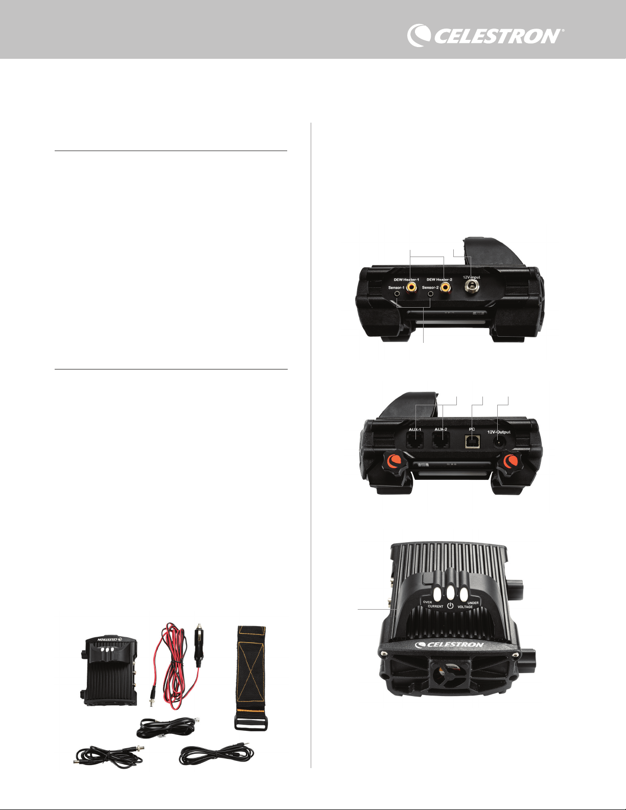
ESPAÑOL | 1
Felicidades por adquirir el Controlador de calefactor de condensación
inteligente x2. Este controlador ofrece un uso de energía "ingeligente"
y eficiente para hasta dos de los calefactores de condensación
del sistema de su telescopio más otro dispositivo de 12V CC -
ofreciendo también la gestión de cables de su instalación. Cuando
conecte sus calefactores de condensación al controlador, un cable lo
conecte todo a su fuente de alimentación, mientras que otro conecta
la instalación a su PC, si lo desea.
Si prefiere no conectar a un PC, conecte sus calefactores de
condensación al controlador y enciéndalo. El controlador monitorizará
automáticamente la temperatura ambiente y la humedad usando
su sensor ambiental integrado. El puerto del termistor monitoriza la
temperatura de la lente y ofrece solamente la energía necesaria para
evitar condensación. Si usa alimentación por batería, este sistema
"inteligente" reduce considerablemente el consumo energético de los
calefactores, aumentando la duración de la batería. Si desea ajustar
manualmente la configuración de los datos del monitor, conecte a un
PC o al mando manual de su soporte Celestron.
1. Lista de piezas
2. Resumen del controlador
ÍNDICE
Fig 1 - Todos los elementos incluidos
Consulte la Figura 2 para un resumen de las tomas de entrada,
puertos de salida, y características del Controlador de calefactor de
condensación inteligente x2.
Si le falta cualquier pieza de la lista de piezas, contacte con el Soporte
Técnico de Celestron en www.celestron.com/pages/technical-
support para obtener ayuda.
1. Lista de piezas . . . . . . . . . . . . . . . . . . . . . . . . . . . . . . . . . . . . . . Pg.1
2. Resumen del controlador . . . . . . . . . . . . . . . . . . . . . . . . . . . . . . . Pg.1
3. Montar el controlador en su instalación . . . . . . . . . . . . . . . . . . Pg.3
4. Alimentar el controlador . . . . . . . . . . . . . . . . . . . . . . . . . . . . . . Pg.4
5. Conectar a un soporte Celestron . . . . . . . . . . . . . . . . . . . . . . Pg.5
6. Usar el controlador con un mando manual Celestron . . . . . . . Pg.5
7. Conexión a PC . . . . . . . . . . . . . . . . . . . . . . . . . . . . . . . . . . . . . . Pg.6
8. Usar el controlador con software CPWI . . . . . . . . . . . . . . . . Pg.7
9. Especificaciones . . . . . . . . . . . . . . . . . . . . . . . . . . . . . . . . . . . Pg.10
Apéndice A:
Ejemplos de determinación de necesidades de alimentación . . Pg.11
CONTROLADOR DE CALEFACTOR Y CONDENSACIÓN INTELIGENTE X2
MANUAL DE INSTRUCCIONES
Modelo #94035
ESPAÑOL
1. Puertos de calefactor de
condensación
2. Toma de entrada de alimentación
3. Puertos de termistor
4. Puertos AUX
5. Puerto de PC
6. Puerto de salida de alimentación
7. Puente
1. 2.
3.
4.
5.
6.
Fig 2-1
Fig 2-2
Fig 2-3
2.
3.
1.
6.
7.
5. 4.
1. Controlador de calefactor de condensación
inteligente x2
2. Cable de alimentación
3. Cable auxiliar
4. Cable de alimentación del soporte
5. Correa para pata de trípode
6. Cable termistor
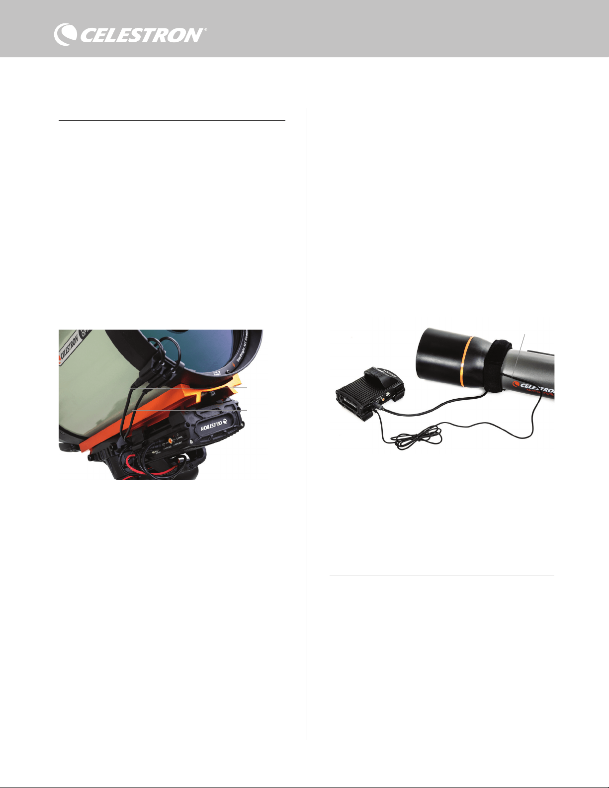
2 | ESPAÑOL
CONTROL DE CALEFACTOR DE CONDENSACIÓN
El Controlador de calefactor de condensación inteligente 2x
proporciona un control "inteligente" automático para hasta dos
arandelas calefactoras de condensación o bandas/tiras de calefactor
de condensación.
Si usa el controlador con una Arandela calefactora de condensación
Celestron, conecte la toma de entrada de alimentación de la arandela
a uno de los puertos de salida de calefactor de condensación del
controlador usando el cable extensor que se incluye con la arandela.
A continuación, conecte el cable termistor incluido a la toma de
termistor de la arandela y el puerto de termistor correspondiente
en el controlador. (Figura 3) El termistor indica la temperatura de la
lente del corrector Schmidt. El controlador usa estos datos, junto con
información del sensor ambiental integrado del controlador (es decir,
temperatura y humedad ambientes) para proporcionar exactamente
la alimentación suficiente a la arandela para evitar la condensación.
Si usa alimentación por batería, el sistema aumenta en gran medida la
duración de la batería en la mayoría de condiciones. Cuando conecte
la arandela a uno de los puertos de calefactor de condensación del
controlador, comenzará a calentarse (a menos que el puerto se haya
desactivado manualmente, lo que se tratará más adelante en este
manual).
Necesitará un cable termistor adicional si desea usar el control
inteligente automático para más de una arandela calefactora de
condensación Celestron. El cable termistor es un cable audio
estándar de 2,5mm, que puede encontrar en la mayoría de tiendas
de electrónica. Asegúrese de obtener uno que sea lo suficientemente
largo para adaptarse a su instalación.
El sensor ambiental del controlador reside en el "puente" de la
carcasa del controlador (Figura 2). La ubicación protege al sensor
del calor que irradia la carcasa, proporcionando igualmente una
buena ventilación. Un sensor ambiental integrado le ofrece una
instalación más simple y ordenada, sin sensores externos colgantes
que molesten.
Ocasionalmente, debería recalibrar el sensor ambiental. La
recalibración calienta el sensor, de forma que la humedad acumulada
se evapore, garantizando los datos de temperatura y humedad
precisos y el uso de energía más eficiente. Recomendamos recalibrar
antes del uso inicial y tras largos periodos de almacenamiento en
condiciones de humedad. El proceso es sencillo; lo explicaremos
más adelante en este manual.
Si no desea usar el control inteligente automático, puede establecer
manualmente la alimentación para cada uno de los puertos de
calefactor de condensación entre 0% (apagado) y 100% (potencia
máxima). Comentaremos esta opción más detalladamente más
adelante en este manual.
Si usa una banda o tira calefactora que no sea de Celestron,
necesitará un conector tipo RCA para conectar a los puertos de
salida de calefactor del controlador. Dispone de dos opciones para
controlar bandas/tiras de terceros:
1. Puede adquirir el termistor opcional para controladores de
calefactor de condensación inteligentes Celestron para
proporcionar control de alimentación inteligente automático.
Conecte la banda calentadora al telescopio y conecte su
conector a uno de los puertos de calefactor de condensación.
A continuación, ponga la punta del termistor de sonda bajo
la banda calentadora de forma que quede asegurado (puede
querer usar cinta). Conecte el conector del termistor a la toma
correspondiente del controlador (Figura 4). El termistor de sonda
no es tan preciso como el termistor integrado de la arandela de
calefactor de condensación de Celestron, que contacta con la
lente correctora directamente. De todos modos, permite el control
inteligente automático de bandas/tiras calefactoras.
2. Alternativamente, puede establecer manualmente la salida de
energía de cada puerto de calefactor de condensación entre 0%
y 100%, como se ha mencionado previamente.
Cada uno de los puertos de calefactor de condensación puede
ofrecer un máximo de 84W de potencia (corriente máxima de 7A),
que debería ser más que suficiente para la mayoría de calefactores
de condensación. Si un calefactor de condensación conectado
consume más de 84W, el puerto se apagará automáticamente para
proteger los circuitos. Tras reducir la carga puede volver a activar
el puerto, un proceso que se tratará más adelante en este manual.
CONTROL DE ALIMENTACIÓN
Una práctica característica del controlador de calefactor de
condensación inteligente 2x es su capacidad de proporcionar
alimentación de 12V CC a un dispositivo externo. Muchos usuarios
eligen alimentar su soporte de este modo, permitiéndoles hacer
funcionar sus calefactores de condensación y soporte desde una
única fuente de alimentación.
Para alimentar un dispositivo de 12V CC, use el cable de
alimentación de soporte incluido - el cable con conectores de cañón
de 12V CC en ambos extremos (Figura 1). Conecte la entrada de
alimentación del dispositivo al puerto de salida de alimentación 12V
CC del controlador. El puerto necesita de un conector de cañón
con punta positiva 12V CC 5,5mm/2,1mm. Un extremo del cable de
alimentación del soporte tiene una rosca integrada en su conector
de cañón. Puede enroscarla a la toma de alimentación de soportes
Celestron con conector de cañón estriado para una conexión más
segura. Fluirá energía por el puerto en cuanto conecte el dispositivo;
no es necesario activar el puerto (a menos que haya desactivado
previamente el puerto, lo que trataremos más adelante).
Fig. 3
Conecte una arandela calefactora de condensación Celestron usando el cable extensor que
incluye la arandela y el cable termistor que incluye el controlador.
Fig. 4
Si usa una banda o tira calentadora de otro fabricante, necesitará el termistor Celestron
opcional para controladores de calefactor de condensación inteligentes.
Termistor Celestron
Cable extensor
Cable termistor
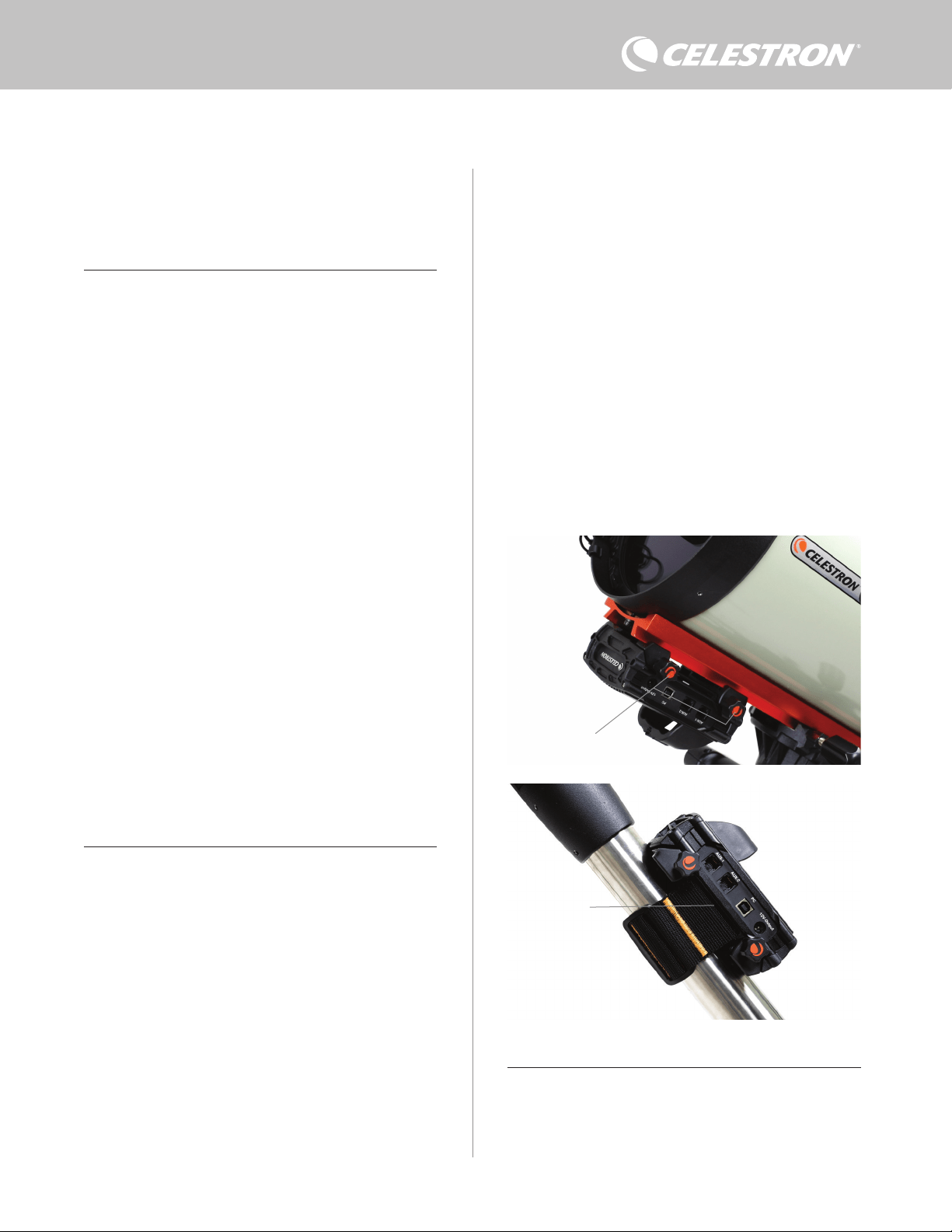
ESPAÑOL | 3
a una barra machihembrada CG-5/Vixen o CGE/Losmandy. Si
tiene una barra machihembrada en su tubo óptico, es posiblemente
la forma más sencilla y práctica para conectar el controlador a su
instalación. Afloje los mandos de fijación del controlador, ponga
las fijaciones del controlador en el raíl machihembrado, y apriete
firmemente los mandos de fijación (Figura 5).
- Use la correa de la pata de trípode incluida para fijar el controlador
a una de las patas de su trípode. Pase la correa por las ranuras
de la parte inferior de la carcasa del controlador, enrolle la correa
alrededor de una de las patas del trípode, apriete la correa con
la hebilla, y asegure el extremo de la correa a sí misma con los
fijadores de gancho de la correa (Figura 6).
- Si la bandeja de accesorios de su trípode es lo suficientemente
grande, puede poner el controlador en la bandeja. Si elige este
método, tenga en cuenta que el controlador no estará asegurado
en posición. Tenga cuidado para evitar tirar de cables con fuerza.
NOTA: ¡NO PONGA EL CONTROLADOR EN EL SUELO! El agua
y la suciedad pueden entrar en el controlador y causar problemas
eléctricos.
USAR EL PUENTE PARA GESTIÓN DE CABLES
El puente de la carcasa aloja el sensor ambiental del controlador,
aislándolo del calor para proporcionar los datos de temperatura y
humedad ambientes más precisos. También hemos diseñado el
puente para que asista con la gestión de cable. Puede pasar cables
bajo el puente para mantenerlos capturados y organizados (Figura
El puerto de alimentación puede ofrecer un máximo de 84W
de potencia (corriente máxima 7A). Si un dispositivo conectado
consume más de 84W, el puerto se apagará automáticamente para
proteger los circuitos. Tras reducir la carga puede volver a activar el
puerto, un proceso que trataremos más adelante.
LED DE ESTADO
Hay tres LED en el puente que indican el estado del controlador:
- El LED central indica si pasa energía por el controlador.
- El LED etiquetado "Corriente excesiva" se enciende si el consumo
de corriente es superior al que puede proporcionar la fuente de
alimentación. Si esto sucede, desconecte o reduzca la energía de
uno de los dispositivos conectados al controlador, o use una fuente
de alimentación capaz de ofrecer más corriente. Deberá establecer
el consumo de corriente máximo para su alimentación para que este
LED funcione correctamente (como se indica más adelante en este
manual).
l Si uno de los puertos ha experimentado un cortocircuito
de un dispositivo conectado, el LED "Corriente excesiva"
parpadeará y el puerto afectado se apagará. Deberá seguir
las instrucciones que aparecen más adelante en el manual
para volver a activar el puerto y usarlo otra vez.
- El LED etiquetado "Tensión insuficiente" se enciende si la potencia
de entrada del controlador es inferior a 11,0V CC. Puede suceder
si la alimentación de su batería está llegando al fin de su carga.
En este caso, debería usar una fuente de alimentación distinta o
recargar la batería. El LED de tensión insuficiente ayuda a proteger
su batería contra un gastado excesivo, lo que puede reducir la vida
útil de recarga de la batería.
l Si la tensión de entrada de la fuente de alimentación excede
13,8V, todos los puertos de salida se apagarán para proteger
los circuitos, y el LED "Tensión insuficiente" parpadeará.
En este caso, debería sustituir la fuente de alimentación
por una que proporcione menos de 13,8V y volver a
activar manualmente todos los puertos de salida según las
instrucciones que aparecen más adelante en este manual.
Si está bajo un cielo oscuro y considera que los LED son demasiado
brillantes, puede ajustar su brillo. Explicaremos el método más
adelante en el manual.
PROTECCIÓN DE CIRCUITO ADICIONAL
Además de las advertencias de los LED de estado, el Controlador de
calefactor de condensación inteligente 2x incluye otras medidas de
protección de circuito para mantener a salvo su equipo.
Si el consumo de energía total del controlador excede 120W
(corriente máxima 10A), el controlador se apagará automáticamente.
Reduzca la carga del controlador y vuelva a activar manualmente los
puertos usando las instrucciones que aparecen más adelante en
este manual.
Si conecta accidentalmente la fuente de alimentación de entrada con
la polaridad incorrecta, el controlador no se encenderá, para evitar
daños a los circuitos.
3. Montar el controlador en su instalación
Decida cómo quiere instalar el controlador en la instalación de su
telescopio. Dispone de varias opciones:
- Use la fijación machihembrada integrada para conectar el controlador
Fig. 6
Ranura de correa
del trípode
Fig. 5
Mandos de fijación

4 | ESPAÑOL
7). Introduzca el extremo del cable bajo el puente y páselo hasta que
quede suficientemente suelto para conectar el conector del cable al
puerto correspondiente del controlador.
4. Alimentar el controlador
Necesitará una fuente de alimentación 12V CC adecuada para
el controlador de calefactor de condensación inteligente 2x. La
alimentación adecuada 12V CC dependerá del equipamiento que
conecte al controlador. La potencia máxima que puede gestionar
el controlador es 120W (corriente máxima 10A a 12V CC), pero
muchos casos de uso necesitan menos energía. Cuando seleccione
una alimentación, es crucial determinar la cantidad aproximada de
energía necesaria para su instalación, y la capacidad de batería que
necesitará para su sesión de observación.
Fórmulas útiles:
- Voltaje (en voltios) x Corriente (en amperios) = Potencia (en vatios)
- Corriente (en amperios) x tiempo (en horas) = Capacidad de
corriente de batería (en amperios-hora) necesaria
- Potencia (en vatios) x tiempo (en horas) = Capacidad de potencia
de batería (en vatios-horas) necesaria
La tensión de entrada máxima de la toma de entrada de energía es de
13,8V CC. Asegúrese de que la tensión de salida de su alimentación
no la exceda. Si se proporciona más de 13,8V CC, todos los puertos
de salida se apagarán automáticamente para proteger los circuitos,
y el LED de estado "Tensión excesiva" del puente de la carcasa
parpadeará.
Deberá elegir entre las siguientes opciones de alimentación:
- Para instalaciones portátiles necesitará una batería 12V CC. Tanto
Celestron PowerTank Lithium Pro como Celestron PowerTank
17AH servirán. Use el cable de alimentación incluido y conecte
el conector del encendedor a la batería, y el conector de cañón
estriado al controlador (Figura 8).
NOTA: Si usa dos calefactores de condensación en condiciones
de condensación intensas y también alimenta un dispositivo
de 12V CC, el controlador puede estar funcionando cerca de
su límite de 120W de potencia (corriente de 10A). En tal caso,
PowerTank Lithium Pro y PowerTank 17AH pueden no tener la
capacidad suficiente para hacer funcionar su instalación toda la
noche. Necesitará una batería con más capacidad.
- Si puede conectar a una toma de alimentación CA, puede usar
un adaptador de CA a 12V CC. Si su instalación precisa de 60W
de potencia o menos (corriente de 5A o menos), puede usar el
adaptador CA 5A de Celestron. Para obtener la conexión más
segura, conecte el cable de salida del adaptador a la toma de
entrada de alimentación del controlador, enrolle el conector del
extremo del cable al exterior de la toma, y conecte a continuación
el adaptador a una salida de alimentación CA (Figura 9).
ADVERTENCIA: LA POTENCIA MÁXIMA QUE PUEDE
ACEPTAR LA TOMA DE ENTRADA ES DE 120W
(CORRIENTE MÁXIMA DE 10A A 12V). Si conecta una fuente
de alimentación capaz de proporcionar más de 120W a la toma
de entrada de alimentación, puede dañar el cable de alimentación
del controlador y el mismo controlador. Si necesita más de 120W,
recomendamos adquirir el Calefactor de condensación inteligente
de y controlador de alimentación 4x de Celestron, que puede
gestionar hasta 240W (corriente máxima 20A).
NOTA: Si se usa cerca de la corriente máxima de 10A, se producirá
una caída de tensión de aproximadamente 1V de la fuente de
alimentación al controlador, debido al cable de alimentación. En
este caso, recomendamos usar una fuente de alimentación que
proporcione ligeramente más de 12V (pero menos de 13,8V).
Consulte el Apéndice A para ver instalaciones de alimentación de
ejemplo como referencia.
Cuando haya elegido su alimentación, necesitará establecer el
consumo máximo de corriente para su alimentación usando el
mando manual de Celestron o CPWI (tratado más adelante en este
manual). Si el controlador consume más corriente que su máximo
especificado, el LED "Corriente excesiva" se encenderá. De forma
predeterminada, el consumo máximo de corriente es de 2,0A, que
es relativamente bajo. Por ello, si no ha establecido el consumo de
corriente máximo para su fuente de alimentación, este LED puede
encenderse de forma prematura.
Fig. 9
Si necesita 5A (60W) de potencia o menos para su instalación, y tiene acceso a una
salida de alimentación CA, puede usar el adaptador CA 5A de Celestron para alimentar el
controlador. Use el conector del cañón estriado para obtener la conexión más segura.
Conector de cañón estriado
Adaptador CA 5A
Fig. 8
Puede usar el cable de alimentación incluido para conectar una batería al controlador. Use
el conector del cañón estriado para obtener la conexión más segura.
PowerTank Lithium Pro
Cable de alimentación
Conector de cañón estriado
El puente de la carcasa se ha diseñado para facilitar la gestión de cables.
Fig. 7
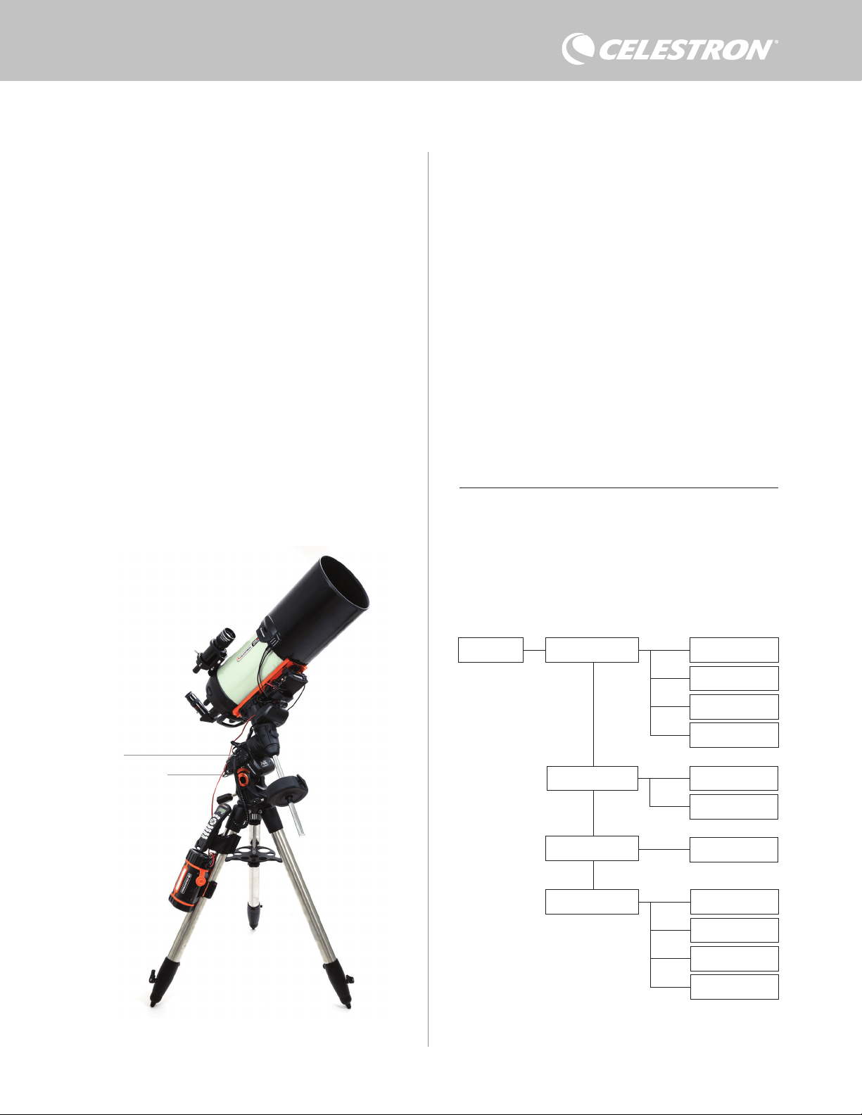
ESPAÑOL | 5
Cuando conecte la alimentación a la toma de entrada de alimentación,
el controlador estará activo. Debería pasar alimentación por los
puertos.
5. Conectar a un soporte Celestron
Si usa el controlador de calefactor de condensación inteligente 2x
con un soporte Celestron, puede conectarlo al soporte para cambiar
la configuración y monitorizar datos con el mando manual del soporte.
Es una opción excelente para instalaciones sin conexión a PC.
Antes de usar el mando manual de su telescopio con el controlador
de calefactor de condensación inteligente 2x, puede tener que
actualizar el firmware de su mando manual. Para el mando manual
NexStar+, necesitará la versión de firmware 5.33.1333 o superior.
Para el mando manual StarSense, necesitará la versión de firmware
1.22.21333 o superior. Puede comprobar el número de versión del
firmware pulsando el botón MENÚ y usar los botones SCROLL y
ENTER para ir a Mando manual>Obtener información de versión.
Use el software Gestor de firmware Celestron (CFM) para actualizar
el firmware si es necesario. Encontrará aquí la última versión: https://
www.celestron.com/pages/drivers-and-software
Para usar el mando manual NexStar+ o StarSense, conecte el cable
AUX incluido a un puerto AUX del soporte Celestron y un puerto
AUX del controlador de calefactor de condensación inteligente 2x. A
continuación, conecte el mando manual del soporte al soporte como
lo haría normalmente. Alternativamente, puede conectar el mando
manual directamente a uno de los puertos AUX del controlador.
También puede usar el cable de alimentación del soporte incluido
para alimentar el soporte desde el puerto de salida de alimentación
(Figura 10).
NOTA: No pasará energía por los puertos AUX a menos que se
conecte un soporte Celestron a uno de los puertos AUX y se
encienda. Si no tiene conectado un soporte Celestron, un mando
manual conectado directamente a uno de los puertos AUX no
recibirá energía.
6. Usar el controlador con un mando
manual Celestron
Cuando esté conectado, puede cambiar la configuración y
monitorizar datos usando el mando manual NexStar+ o StarSense.
Para hacerlo, encienda el soporte, pulse el botón MENÚ en el mando
manual, vaya al menú del calefactor de condensación usando los
botones SCROLL y pulse ENTER. Ahora, use los botones SCROLL
para ver las opciones del menú del calefactor de condensación, y
pulse ENTER para seleccionar.
La Figura 11 muestra el árbol del menú del calefactor de
condensación.
NOTA: Si usa el mando manual StarSense, deberá usar los botones
SCROLL para ver todo el texto de algunas selecciones del menú.
POTENCIA DE ENTRADA
Seleccione esta opción para monitorizar el consumo de energía
de los dispositivos conectados al controlador. También puede
comprobar la corriente de entrada de la fuente de alimentación
y establecer el consumo máximo de corriente. Use los botones
SCROLL del mando manual para seleccionar entre las siguientes
opciones, y pulse ENTER para seleccionar.
l Estado de energía – Muestra el consumo de energía de los
dispositivos conectados al controlador.
Dew Heater Input Power
Power Status
Voltage Status
Current Status
Current Limit
Dew Heater #1
Dew Heater #2
Power #1
Ambient Temp
Humidity
Dew Point
Recalibration
Dew Heater Ports
Power Ports
Environment
Árbol del menú de calefactor de condensación del mando manual
Fig. 11
Fig. 10
El cable AUX incluido permite que el soporte se comunique con el controlador. También
puede usar el cable de alimentación del soporte incluido para alimentar el soporte desde el
puerto de salida de alimentación.
Cable AUX
Cable de alimentación
del soporte

6 | ESPAÑOL
l Estado de tensión – Muestra la tensión proporcionada por la
fuente de alimentación de entrada.
l Estado de corriente - Muestra la corriente que usan los dispositivos
conectados al controlador.
l Límite de corriente – Este menú le permite establecer la corriente
máxima de la fuente de alimentación. Cuando el consumo de
corriente de los dispositivos conectados exceda esta cantidad,
el LED "Corriente excesiva" del puente del controlador se
encenderá. Pulse ENTER para establecer el límite de corriente de
1,0A a 10,0A. Pulse ENTER cuando haya terminado.
NOTA: Si excede el límite de corriente y el LED "Corriente excesiva"
se enciende, deberá desconectar un dispositivo del controlador
o usar otra fuente de alimentación que pueda proporcionar más
corriente. Si usa otra alimentación, asegúrese de cambiar el límite
de corriente.
PUERTOS DE CALEFACTOR DE CONDENSACIÓN
Esta opción muestra el consumo de energía de cada puerto de
calefactor de condensación. Si no desea usar el control "inteligente"
automático de los calefactores de condensación, aquí establecerá
manualmente la salida de energía para cada puerto de calefactor de
condensación.
Tras seleccionar Puertos de calefactor de condensación del menú,
puede ir a los dos puertos de calefactor. Para cada puerto de calefactor,
el LCD del mando manual mostrará si el puerto está en modo Manual o
Auto y el consumo de energía del puerto en ese momento.
Para cambiar de modo Auto a modo Manual, seleccione el puerto con
los botones SCROLL y pulse ENTER. Use los botones SCROLL para
elegir entre modo Manual y modo Automático, y pulse ENTER.
- Si selecciona modo Manual, necesitará especificar el nivel de energía
deseado. Es un número entre 0 y 100 - el porcentaje de energía
máximo al calefactor de condensación conectado al puerto. Cuando
haya introducido el valor deseado, pulse ENTER. Para apagar un
puerto de calefactor de condensación, seleccione el puerto de
calefactor de condensación, cambie a modo Manual, y ponga el nivel
de energía al 0%.
- Si selecciona el modo Automático, deberá establecer el nivel
de agresividad. Es un número de 1 (agresividad más baja) a
10 (agresividad más elevada) que indica lo activo que está el
controlador de condensación inteligente al evitar la condensación.
Una configuración de agresividad más alta usará más energía pero
proporcionará el nivel más alto de prevención de condensación
al cambiar las condiciones ambientales. En general, puede usar
una configuración de agresividad más baja para ubicaciones de
observación más cálidas y secas, y una configuración mayor para
lugares de observación más fríos y húmedos. Igualmente, use una
configuración de agresividad superior para aperturas más grandes,
y una agresividad menor si usa un escudo de condensación o hace
viento. Si no está seguro de la configuración de agresividad que debe
usar, pruebe inicialmente con 5 (la configuración predeterminada).
Cuando haya establecido la agresividad, pulse ENTER.
PUERTO DE ALIMENTACIÓN
Esta selección le permite monitorizar la salida de alimentación 12V
CC a un dispositivo conectado al puerto de alimentación.
Si se conecta un dispositivo al puerto y selecciona "Puerto de
alimentación" en el menú del calefactor de condensación, el LCD
mostrará el consumo de energía. Para desactivar la alimentación al
puerto para apagar un dispositivo conectado, pulse ENTER para
el puerto seleccionado. La pantalla LCD mostrará "¿Desactivar
puerto?" Para continuar, pulse ENTER. Si no desea desactivar la
alimentación, pulse BACK. Para volver a activar la alimentación del
puerto y volver a activar un dispositivo conectado, pulse ENTER de
nuevo.
AMBIENTE
Esta selección le permite ver los datos del sensor ambiental. Aquí
también puede recalibrar el sensor para un rendimiento óptimo. Use
los botones SCROLL del mando manual para seleccionar entre las
siguientes opciones, y pulse ENTER para seleccionar.
l Temperatura ambiente – Muestra la temperatura del aire ambiente.
l Humedad – Muestra la humedad relativa.
l Punto de condensación – Este valor se calcula en tiempo real
usando datos de temperatura y humedad ambientes. Si la
temperatura de la lente cae por debajo el número mostrado, se
formará condensación en su superficie.
l Recalibración – Para comenzar a recalibrar el sensor ambiente,
seleccione esta opción y pulse ENTER. El sensor se calentará
para evaporar la humedad que se haya acumulado en él,
ofreciendo las lecturas de sensor más precisas. La recalibración
tarda aproximadamente 10 minutos desde el momento en que
pulsa ENTER hasta que el sensor se haya enfriado hasta la
temperatura ambiente. Recomendamos recalibrar el sensor
ambiental periódicamente, especialmente si el sensor no se ha
usado durante bastante tiempo o se ha guardado en condiciones
de humedad.
n Si comprueba la temperatura o humedad ambientes
durante la recalibración, la pantalla informará de los valores
detectados la última vez antes de iniciar la recalibración.
VOLVER A ACTIVAR UN PUERTO DESACTIVADO
Como se ha indicado previamente, los puertos del controlador se
apagan automáticamente si uno de los puertos consume más de
84W (corriente máxima 7A) o si la carga total del controlador excede
120W (corriente máxima 10A). Para volver a activar un puerto cuando
se haya desactivado automáticamente:
l Primero, reduzca la carga del controlador.
l Para seleccionar el puerto desactivado, pulse MENÚ, vaya a
"Calefactor de condensación" y pulse ENTER. Vaya a "Puerto
de calefactor de condensación" o "Puerto de alimentación" y
pulse ENTER.
l La pantalla LCD mostrará "¿Restablecer fusible?” Pulse ENTER
para volver a activar el puerto.
NOTA: Si la carga total del controlador excede 120W (corriente
máxima 10A), deberá volver a activar todos los puertos.
7. Conexión a PC
Puede ser práctico en algunas instalaciones conectar el controlador
de calefactor de condensación inteligente 2x a un PC para ajustar
la configuración y monitorizar datos. Es especialmente el caso si ya
usa un PC para controlar el soporte o cualquier cámara de captura
o cámaras de guía.
Para usar una conexión cableada, necesitará un cable USB de tipo
A a tipo B (no incluido). Conecte al puerto de PC del controlador y
un puerto USB de su PC. Cuando active el controlador, el ordenador
debería reconocerlo.
Si usa un soporte informatizado Celestron, puede conectar al soporte
y controlarlo con el Controlador de calefactor de condensación
inteligente usando el software para PC gratuito CPWI. Para hacerlo,
use el cable AUX incluido para conectar uno de los puertos AUX del
controlador a uno de los puertos AUX del soporte.
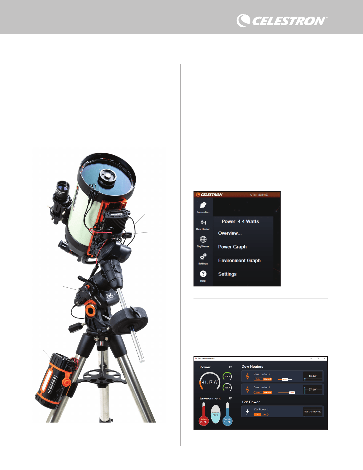
ESPAÑOL | 7
8. Usar el controlador con software CPWI
Si ya controla su telescopio o cámara desde un ordenador,
le encantará controlar el controlador de calefactor de
condensación inteligente 2x con nuestro software gratuito
CPWI de Celestron. Para descargar la última versión, visite:
https://www.celestron.com/pages/celestron-pwi-telescope-control-
software
Instale el software y abra CPWI. Seleccione "Iniciar" si se muestra
la ventana inicial. A continuación, pulse el icono "Conexión" en la
esquina superior izquierda de la pantalla. Si usa una conexión
cableada, seleccione "Montar USB". Si usa el módulo WiFi
SkyPortal, pulse el icono "Conexión" y seleccione "WiFi".
CPWI debería encontrar y conectar con el controlador. Cuando esté
conectado, el icono del calefactor de condensación aparecerá en el
menú de selección del lado izquierdo de la pantalla.
Seleccionar el icono del calefactor de condensación mostrará el
menú del calefactor de condensación. (Figura 13). La primera línea
del menú del calefactor de condensación indica el consumo de
energía total de los dispositivos conectados al controlador. Para ver
más datos, pulse Resumen.
RESUMEN
La pantalla Resumen muestra el consumo de energía de cada
puerto del controlador (Figura 14). Los iconos al lado de los puertos
que estén en uso se pondrán naranjas con el consumo de energía
con el tiempo en la pequeña gráfica de la derecha. En la esquina
superior izquierda de la pantalla Resumen, puede ver la energía total
y el consumo de corriente del controlador, así como la tensión de
entrada de la fuente de alimentación. Debajo puede ver los datos de
temperatura y humedad ambientes del sensor ambiental y el punto de
condensación calculado.
Para conectar un PC al controlador de forma inalámbrica usando el
módulo WiFi SkyPortal opcional, necesitará un soporte Celestron
y el accesorio de módulo WiFi (vendidos por separado). Conecte
el módulo WiFi a un puerto AUX del soporte. Conecte otro puerto
AUX del soporte a uno de los puertos AUX del controlador con el
cable AUX incluido. También puede usar el cable de alimentación del
soporte incluido para alimentar el soporte desde uno de los puertos
de salida de alimentación (Figura 12). Cuando estén conectados
todos los cables, encienda el soporte.
NOTA: Si su soporte solamente tiene un puerto AUX, deberá adquirir
el divisor de puerto AUX opcional. Esto convertirá el puerto AUX del
soporte en dos puertos AUX.
Fig. 13
Menú del calefactor de
condensación CPWI
Fig. 14
Pantalla de resumen
Fig. 12
Si usa un soporte Celestron con el módulo WiFi SkyPortal, puede conectar al controlador
por WiFi mediante el soporte usando el cable AUX incluido. También puede usar el cable
de alimentación del soporte incluido para alimentar el soporte desde el puerto de salida de
alimentación.
Cable de alimentación
del soporte
Módulo WiFi SkyPortal
PowerTank Lithium Pro
Cable AUX
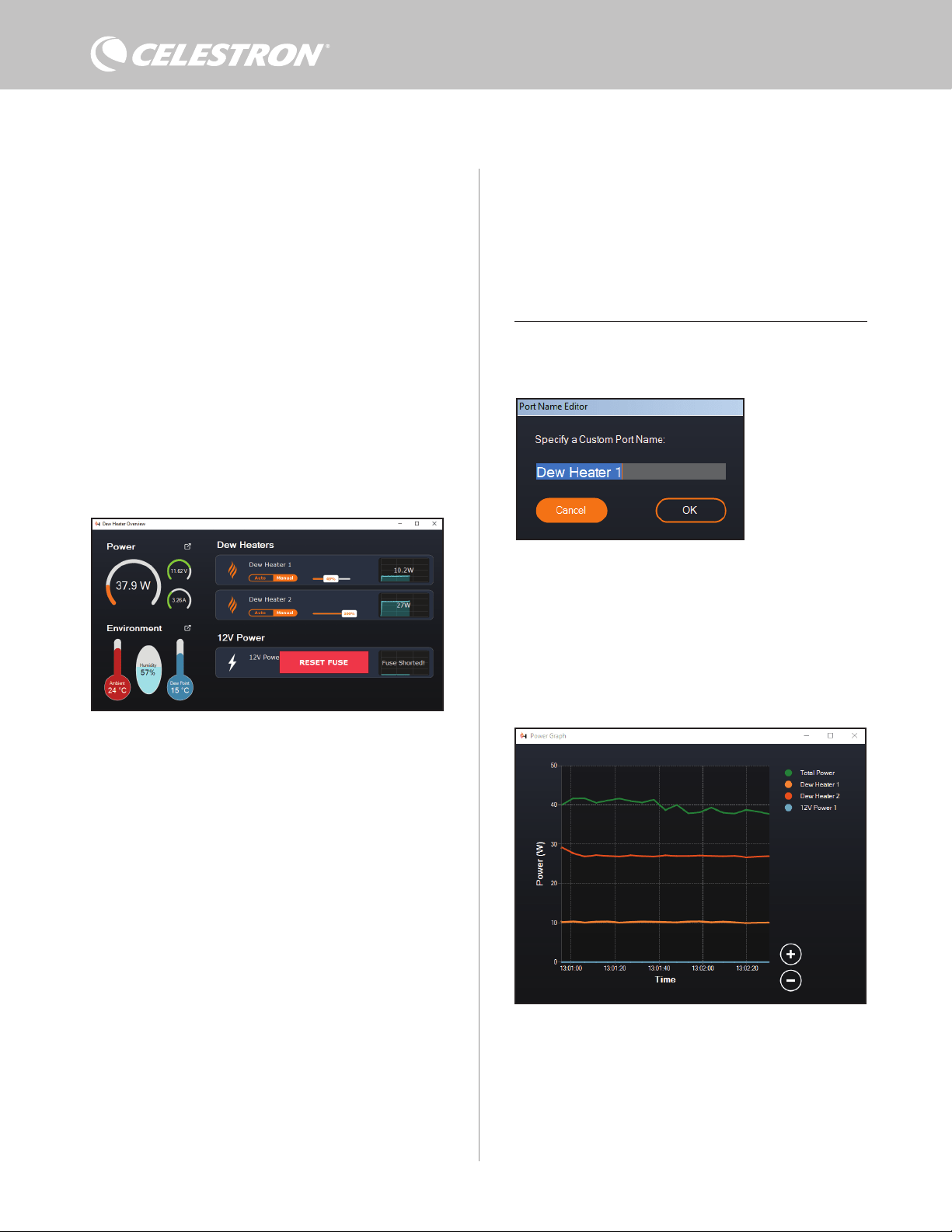
8 | ESPAÑOL
El menú Resumen también es donde puede activar o desactivar
cada puerto de salida, incluyendo ambos puertos de calefactor
de condensación y el puerto de salida de alimentación. Si accede
de forma remota al PC conectado al controlador, puede activar y
desactivar remotamente sus dispositivos desde aquí. Para el puerto
de alimentación, use el botón ENCENDIDO/APAGADO. Para los
puertos de calefactor de condensación, seleccione "Manual" y
ponga el nivel de energía en cero.
Como se ha indicado previamente, el controlador apagará los
puertos automáticamente la carga es excesiva en uno de los puertos
(superior a 84W) o si la carga total del controlador excede 120W
(corriente máxima 10A). Si esto sucede, la notificación Fusible
quemado aparecerá, y verá una casilla RESTABLECER FUSIBLE
al lado del(los) puerto(s) afectado(s) en la pantalla Resumen (Figura
15). Para volver a activar un puerto cuando se haya desactivado
automáticamente, reduzca primero la carga del puerto según
sea necesario. A continuación pulse la casita "RESTABLECER
FUSIBLE" para volver a activar la alimentación del puerto.
NOTA: Si la carga total del controlador excede 120W (corriente
máxima 10A), deberá volver a activar todos los puertos.
En cada puerto de calefactor de condensación encontrará botones
Puede renombrar cada puerto en la pantalla Resumen pulsando en el
nombre del puerto. Aparecerá la ventana Editor de nombre de puerto
(Figura 16) y podrá introducir el nuevo nombre. Pulse el botón OK
cuando termine, el nuevo nombre aparecerá en el puerto. Le ayudará
a mantener organizados sus controles, dado que puede renombrar
cada puerto para el dispositivo conectado. Por ejemplo, puede
renombrar sus puertos "Arandela calefactora de condensación de 8
pulgadas" o "Soporte CGX".
GRÁFICA DE ENERGÍA
Seleccione "Gráfica de energía" del menú del calefactor de
condensación para mostrar la ventana de la Gráfica de energía
(Figura 17). También puede acceder directamente a la gráfica de
energía desde la pantalla Resumen pulsando el icono de flecha de
acceso directo al lado del término "Energía" en la sección superior
izquierda de la pantalla Resumen.
La gráfica de energía muestra el uso de energía con el tiempo de
todos los dispositivos conectados a los puertos de calefactor de
condensación y el puerto de salida de alimentación. Cada línea de
color de la gráfica representa un puerto distinto. Si desea cambiar el
color de un puerto, ponga el ratón sobre el puerto y pulse el botón
derecho.
Puede ocultar un puerto de la gráfica pulsando en el círculo de la
izquierda del nombre del puerto. Para volver a habilitar su línea en la
gráfica, pulse otra vez en el círculo.
Para "aumentar" una gama de tiempo específica de la gráfica para
ver más detalles, use los círculos "+" y "-" en la parte inferior izquierda
Fig. 17
Ventana de gráfica de energía
Fig. 15
Si el consumo de energía de un puerto excede 84W, el puerto se apagará automáticamente.
Para volver a activarlo, reduzca la carga en el puerto afectado y pulse la casilla
RESTABLECER FUSIBLE.
Fig. 16
Ventana de editor de nombre
de puerto
para cambiar del modo de control "inteligente" automático a modo
de control manual:
- Si selecciona modo Manual, necesitará especificar el nivel de
energía deseado. Es un número entre 0 y 100 - el porcentaje de
energía máximo al calefactor de condensación conectado al
puerto. Cuando haya introducido el valor deseado, pulse ENTER.
l Para apagar un puerto de calefactor de condensación,
seleccione control manual y ponga el deslizador al 0%.
- Si selecciona el modo Automático, deberá establecer el nivel
de "agresividad". Es un número de 1 (agresividad más baja) a
10 (agresividad más elevada) que indica lo activo que está el
controlador al evitar la condensación. Una configuración de
agresividad más alta usará más energía pero proporcionará
el nivel más alto de prevención de condensación al cambiar
las condiciones ambientales. En general, puede usar una
configuración de agresividad más baja para ubicaciones de
observación más cálidas y secas, y una configuración mayor para
lugares de observación más fríos y húmedos. Igualmente, use una
configuración de agresividad superior para aperturas más grandes,
y una agresividad menor si usa un escudo de condensación o hace
viento. Use el deslizador para establecer la agresividad. Si no está
seguro de la configuración de agresividad que debe usar, pruebe
inicialmente con 5 (la configuración predeterminada).

ESPAÑOL | 9
usa la escala de % de humedad a la derecha de la gráfica. Cada línea
de color de la gráfica representa un valor distinto. Si desea cambiar
el color de un valor, ponga el ratón sobre el puerto y pulse el botón
derecho.
Puede ocultar un valor de la gráfica pulsando en el círculo de la
izquierda del nombre del valor en la gráfica. Para volver a habilitar su
línea en la gráfica, pulse otra vez en el círculo.
Para "aumentar" una gama de tiempo específica de la gráfica para
ver más detalles, use los círculos "+" y "-" en la parte inferior izquierda
de la gráfica. También puede "hacer pinza para aumentar" si tiene
un panel táctil o usar la rueda de desplazamiento del ratón para
aumentar y reducir las gamas de tiempo. Use el deslizador de la parte
inferior de la gráfica para encontrar una gama de tiempo específica.
Para cambiar las unidades de temperatura de grados Fahrenheit
(predeterminado) a grados Celsius, use la selección "Configuración"
del menú del calefactor de condensación.
CONFIGURACIÓN
La selección "Configuración" del menú de calefactor de
condensación muestra la ventana de Configuración de calefactor de
condensación (Figura 19).
- Límite de corriente
l Use el deslizador para establecer la corriente máxima para
Fig. 18
Ventana de gráfica ambiental
Fig. 19
Ventana de configuración de calefactor de condensación
de la gráfica. También puede "hacer pinza para aumentar" si tiene
un panel táctil o usar la rueda de desplazamiento del ratón para
aumentar y reducir. Use el deslizador de la parte inferior de la gráfica
para encontrar una gama de tiempo específica.
GRÁFICA AMBIENTE
Seleccione "Gráfica ambiente" del menú del calefactor de
condensación para mostrar la ventana de la Gráfica ambiente (Figura
18). También puede acceder directamente a la gráfica ambiente
desde la pantalla Resumen pulsando el icono de flecha de acceso
directo al lado del término "Ambiente" en la sección izquierda de
la pantalla Resumen. Esta gráfica muestra la temperatura del aire
ambiente, humedad y punto de condensación calculado con el
tiempo. La temperatura del aire y el punto de condensación usan la
escala de temperatura °C a la izquierda de la gráfica. La humedad
la alimentación que use. Si el consumo de energía del
controlador excede la corriente máxima establecida, el LED
"Corriente excesiva" del puente de la carcasa del controlador
se encenderá. Si esto sucede, deberá reducir el consumo de
energía reduciendo o apagando dispositivos conectados al
controlador. Alternativamente puede usar otra alimentación
capaz de proporcionar más corriente. Si lo hace, asegúrese
de ajustar el límite de corriente de la forma correspondiente.
- Unidades de temperatura
l Cambie las unidades de temperatura en CPWI usando los
botones °C y °F.
- Recalibración de sensor ambiente
l Use el botón "Iniciar recalibración" para recalibrar el sensor
ambiente. Calentará el sensor para evaporar humedad que tenga
acumulada. La recalibración ayuda a proporcionar las lecturas
de sensor más precisas. El sensor tarda aproximadamente 10
minutos en calentarse y volver a enfriarse. Recomendamos
recalibrar el sensor ambiental periódicamente, especialmente
si el sensor no se ha usado durante bastante tiempo o se ha
guardado en condiciones de humedad. Ayudará a proporcionar
el uso de energía más eficiente para los calefactores de
condensación.
n Si comprueba la temperatura o humedad ambientes
durante la recalibración, la pantalla informará de los
valores detectados la última vez antes de iniciar la
recalibración.
- Brillo LED
l Establezca el brillo de los LED del controlador usando el
deslizador. Uno es la posición más tenue, y diez la más
brillante.
- Apagar al desconectar
l Puede elegir apagar todos los dispositivos conectados cuando
desconecte el controlador de CPWI. Para hacerlo, pulse
el botón Habilitar. Cuando vuelva a conectar CPWI, todos
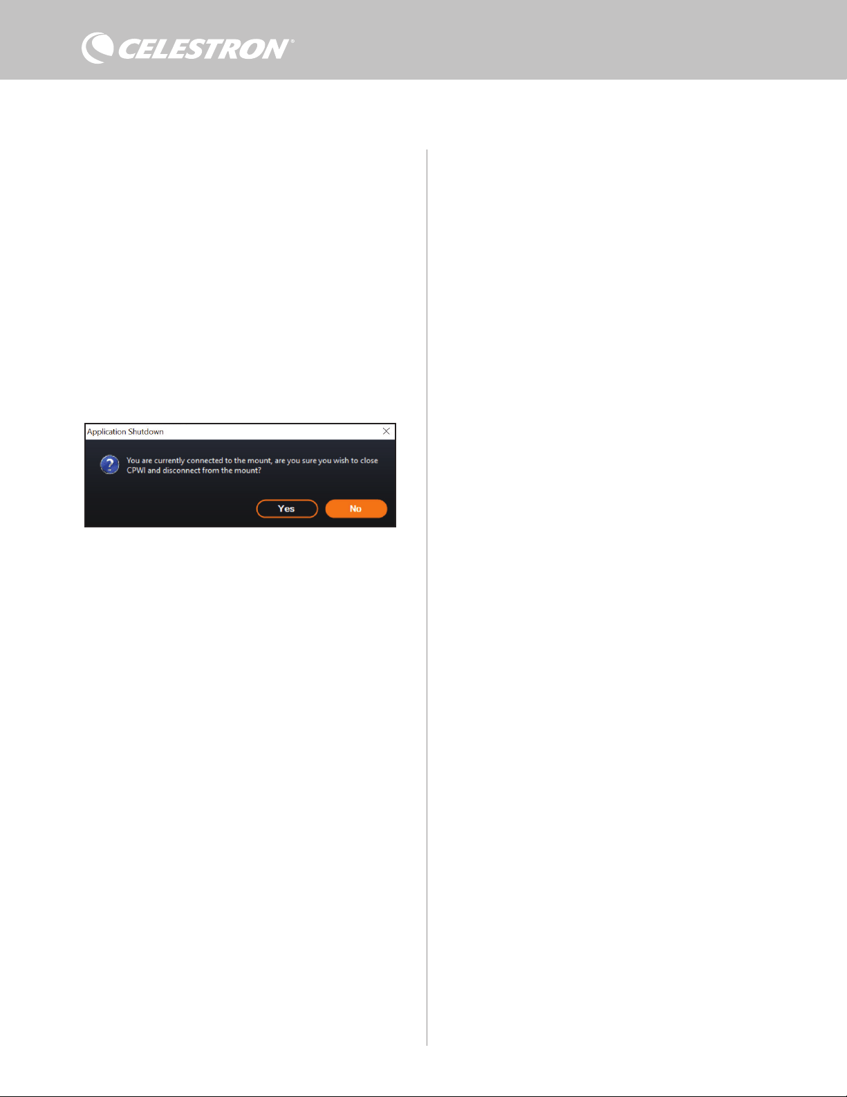
10 | ESPAÑOL
los puertos volverán a activarse. Si no habilita esta función,
pasará energía por el controlador del modo habitual cuando
desconecte de CPWI.
- Guardar datos
l Esta función le permite exportar los datos brutos del controlador
en formato .CSV, que puede abrir en Microsoft Excel o Google
Sheets. Si selecciona esta opción, encontrará el archivo .CSV
guardado en esta carpeta de su PC: Documentos\Celestron\
CPWI
Para desconectar del Controlador de calefactor de condensación
inteligente 2x al finalizar la sesión de observación, puede cerrar
CPWI, se mostrará la ventana de Apagado de aplicación (Figura
20), o puede seleccionar el icono "Conexión" en la esquina superior
izquierda y seleccionar "Desconectar". Si ha seleccionado "Apagar al
desconectar" del menú Calefactor de condensación>Configuración,
todos los dispositivos conectados al controlador se apagarán.
En caso contrario seguirá pasando energía por los puertos del
controlador del modo habitual.
Fig. 20
Ventana de apagado de aplicación
9. Especificaciones
Peso: 1,2 lbs.
Dimensiones: 5,5” x 4,5” x 3,25”
Carcasa: Aluminio, ventilación por ventilador, fijaciones
machihembradas integradas y correa para trípode
Alimentación: 12V CC nominal, 13,8V CC de tensión máxima
de entrada, corriente máxima de entrada 10A, conector de cañón
estriado de punta positiva 5,5mm/1,2mm
Puerto de salida de alimentación: 12V CC, conector de cañón
de punta positiva 5,5mm/2,1mm, corriente de salida máxima 7A
Salidas de calefactor de condensación: 2x tomas RCA, 12V CC,
corriente de salida máxima 7A para cada puerto
Toma termistor: 2x toma audio de 2,5mm, compatible con
arandelas calefactoras de condensación Celestron y Termistor
Celestron opcional
Puertos AUX: 2x puertos AUX, compatibles con soportes Celestron
y otros productos Celestron
Sensor ambiental: Integrado, ofrece datos de temperatura y
humedad ambientes, puede recalibrarse para mejorar el rendimiento
Protección de circuito: fusibles restablecibles internamente para
cada puerto, protección de polaridad inversa, baja tensión, tensión
excesiva, baja corriente, corriente excesiva
Firmware: Actualizable con el software Gestor de firmware de
Celestron (CFM)
Cable de alimentación: Conector de cañón de punta positiva
estriado 5,5mm/2,1mm en un extremo, conector de encendedor en
el otro extremo, fusible de 10A, cable de calibre 16

ESPAÑOL | 11
Apéndice A: Ejemplos de determinación
de necesidades de alimentación.
INSTALACIÓN DE EJEMPLO #1
- Arandela calefactora de condensación Celestron de 8” conectada
a puerto de calefactor de condensación #1
l Consumo máximo de corriente de arandela de calefactor de
condensación de 8” = 1,7A
l Potencia máxima necesaria para arandela calefactora de
condensación de 8” = 12V x 1,7A = 20,4W
- Soporte EQ avanzado VX de Celestron conectado al puerto de
alimentación #2
l Consumo de corriente máximo para soporte EQ avanzado VX al
desplazarse a máxima velocidad = aproximadamente 2,0A
l Potencia máxima necesaria para avanzado VX al desplazarse a
máxima velocidad = 12V x 2,0A = 24,0W
En este ejemplo, la potencia máxima que precisa el controlador sería
de aproximadamente 48W.
- Si tiene acceso a alimentación CA, el adaptador CA 5A Celestron,
que puede gestionar hasta 60W, sería una buena elección para
alimentar el controlador.
- Para instalaciones portátiles, Celestron PowerTank Lithium Pro
puede proporcionar hasta 120W de potencia (corriente máxima
10A), por lo que debería funcionar bien con esta instalación de
ejemplo.
l La capacidad de batería de PowerTank Lithium Pro es 158.7
vatios-horas. El controlador usa aproximadamente 48 vatios de
potencia por hora. Por lo tanto, la batería durará más de 3 horas
en este ejemplo. Supongamos que usa un control inteligente
automático para la arandela calefactora de condensación. En
este caso, puede esperar que la batería dure notablemente
más tiempo, dado que la arandela probablemente no funcione
continuamente a máxima potencia. De forma similar, si no
desplaza repetidamente el telescopio a máxima velocidad,
la potencia consumida por el soporte será mucho menor,
aumentando más la duración de la carga de la batería.
INSTALACIÓN DE EJEMPLO #2
- Arandela calefactora de condensación Celestron de 11”
conectada a puerto de calefactor de condensación #1
l Consumo máximo de corriente de arandela de calefactor
de condensación de 11” = 2,5A
l Potencia máxima necesaria para arandela calefactora
de condensación de 11” = 12V x 2,5A = 30,0W
- Banda/tira calefactora de otro fabricante para catalejo de guía
conecta a puerto de calefactor de condensación #2
l Consumo máximo de corriente para banda/tira calefactora
del catalejo de guía = aproximadamente 1,0A
l Potencia máxima necesaria para banda/tira calefactora
para catalejo de guía = 12V x 1,0A = 12,0W
- Soporte EQ CGX de Celestron conectado al puerto de
alimentación #2
l Consumo de corriente máximo para soporte EQ CGX al
desplazarse a máxima velocidad = aproximadamente 3,0A
l Potencia máxima necesaria para soporte EQ CGX al
desplazarse a máxima velocidad = 12V x 3,0A = 36,0W
En este ejemplo, la potencia máxima que precisa el controlador sería
de aproximadamente 78W.
- Si tiene acceso a alimentación CA, una fuente de alimentación CA
a CC de alta potencia servirá bien para alimentar el controlador.
El adaptador CA 5A de Celestron no funcionaría, dado que su
máximo es 60W.
l Si la tensión de alimentación CA a CC es variable, asegúrese
de establecerla en 12V antes de conectarla al controlador.
Igualmente, recuerde que la toma de entrada de alimentación
es de punta positiva.
- Para instalaciones portátiles, Celestron PowerTank Lithium Pro
puede proporcionar hasta 120W de potencia (corriente máxima
10A), por lo que debería funcionar con esta instalación de
ejemplo. Sin embargo, puede no tener la suficiente capacidad de
almacenamiento para toda su sesión de observación.
l La capacidad de batería de PowerTank Lithium Pro es 158.7
vatios-horas. El controlador usará aproximadamente 78
vatios de potencia por hora. Por lo tanto, la batería duraria
aproximadamente 2 horas en este ejemplo. Supongamos
que usa un control inteligente automático para la arandela
calefactora de condensación. En este caso, puede esperar
que la batería dure notablemente más tiempo, dado que
la arandela probablemente no funcione continuamente
a máxima potencia. De forma similar, si no desplaza
repetidamente el telescopio a máxima velocidad, la potencia
consumida por el soporte será mucho menor, aumentando
más la duración de la carga de la batería.
- Para instalaciones portátiles que tenga planeado hacer funcionar
toda la noche, recomendamos una "batería marítima" de 12V CC u
otra batería de 12V CC con elevada capacidad de almacenamiento.
l Si tiene pensado fotografiar toda la noche (8 horas) con
esta instalación, necesitaría una batería marítima con una
capacidad de 78W x 8 hours = 624 vatios-horas (es decir,
aproximadamente 52 amperios-horas a 12V CC).
12 | ESPAÑOL
NOTA FCC: Este equipo ha sido probado y cumple con los límites de un dispositivo digital de Clase B, según el apartado
15 de las normas FCC. Estos límites están diseñados para proporcionar una protección razonable contra interferencias
dañinas en una instalación doméstica. Este equipo genera, usa e irradia energía de radiofrecuencia y, si no se instala
y utiliza de acuerdo con las instrucciones, puede provocar interferencias dañinas en comunicaciones por radio. Sin
embargo, no existe ninguna garantía de que no se produzcan interferencias en una instalación concreta. Si este equipo
causa interferencias dañinas en la recepción de radio o televisión, lo que puede determinarse apagando y encendiendo
el equipo, se recomienda al usuario intentar corregir las interferencias con una o varias de las medidas siguientes:
• Reorientar o recolocar la antena receptora.
• Aumentar la separación entre el equipo y el receptor.
• Conectar el equipo a una toma de un circuito distinto al que esté conectado el receptor.
• Consultar al vendedor o a un técnico experimentado de radio/TV para obtener ayuda.
Este dispositivo cumple con el apartado 15 de las normas FCC. Su uso está sujeto a las dos condiciones siguientes:
(1) este dispositivo no puede causar interferencias nocivas, y (2) este dispositivo debe admitir cualquier interferencia
recibida, incluidas las interferencias que puedan causar un funcionamiento indeseado.
Tenga en cuenta que los cambios o modificaciones no aprobadas explícitamente por la parte responsable del cumplimien-
to pueden anular la autoridad del usuario para usar el equipo.
El diseño y las especificaciones del producto están sujetos a cambios sin notificación previa.
Este producto ha sido diseñado y está pensado para ser usado por personas de 14 años o más de edad.
Fabricado en China
©2022 Celestron. Celestron y su símbolo son marcas comerciales de Celestron, LLC. •
Todos los derechos reservados. • Celestron.com • 2835 Columbia Street, Torrance, CA
90503 EE.UU.
celestron.com/pages/technical-support
10-22
celestron.com/pages/war ranty