
1 / 24
Number: JT190199989 Version Number: A1
Note: Subsequent versions of this specification are subject to change without prior notice. Thank you
Content
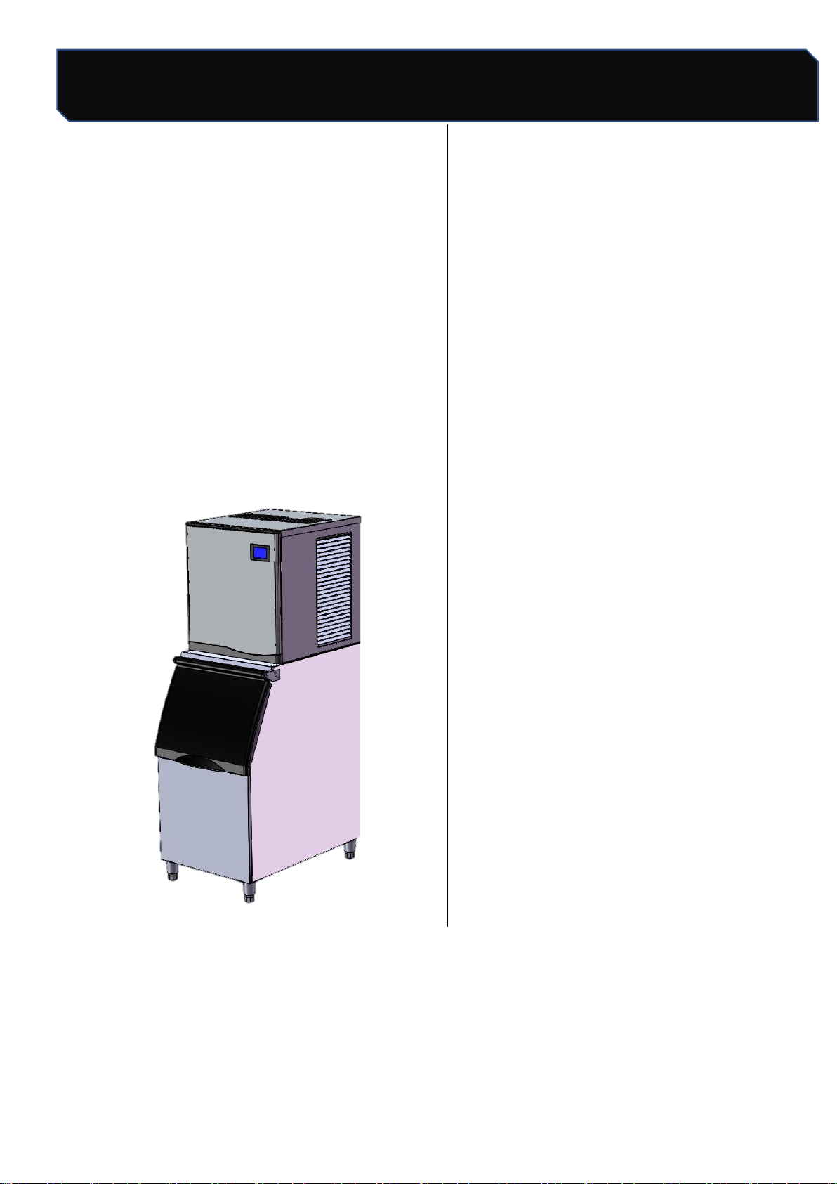
Ice Machine Series
Installation maintenance
instructions
This specification contains the following
LB300TA,LB400TA
Content
1. Features ----------------------------------3
2.
Appearance & Size------------- -----------3
3. Unpacking ---------------------------4
4. Installation location ---------------------4
5. Leveling Adjustment --------------------4
6. Water Supply/Purge-----------------5
6.1 Water Supply ------------------------5
6.2 Drainage-----------------------------5
7. Power supply ----------------------------6
8. Sanitation after Installation ------------6
9. Post-installation inspection ------------6
10. Operation --------------------------------7
11. Working process -------------------9
12. Check Before Start -------------------9
13. Conventional cleaning ----------------10
13.1 Shell Dismantling ----------------10
13.2 Evaporator Cleaning --------------11
13.3 Flume cleaning -------------------11
13.4 Cleaning of condensers ---------12
14. Cleaning & Disinfection -------------13
14.1 Cleaning process -----------------14
14.2 Disinfection process -------------15
14.3 Removal / Installation of Parts --16
15. Out of use/Winterization -------------18
16. Maintenance ---------------------------18
17. Circuit diagram ------------------------19
18. Exploded drawing ---------------------20
Safety Tips
2 / 24
Number: JT190199989 Version Number: A1
Note: Subsequent versions of this specification are subject to change without prior notice. Thank you
Safety Tips
When operates and maintains an ice maker , be sure to pay attention to the safety tips in the manual.
Ignoring these tips may result in personal injury and ice maker damage.
In this manual, you will see the following forms of security tips:
Warning
Potential personal injury, failure to install in accordance with this manual, or use of unauthorized
modified machines may cause personal injury.
Note
The correct installation, usage and maintenance of the ice maker is very important to the output
of the ice maker and reduce the failure rate. Please read and understand this manual. which
contains valuable information on installation. usage and maintenance. If you encounter problems
not covered in this manual, you may contact our company or our service provider at any time.
warranty.
Important
The mentioned information about adjustment,maintenance and sanitation is not subject of the
range of warranty clause.
Please preserve this manual well
The manual is an integral part of the product, please keep it properly. Be sure to read carefully the
warnings, notices and important matters described in this manual, because these warnings, notices and
important matters provide the installer/user with important information needed for proper installation,
continuous and safe use and maintenance of the product. Please keep this manual for reference when
necessary.
Safety Tips
3 / 24
Number: JT190199989 Version Number: A1
Note: Subsequent versions of this specification are subject to change without prior notice. Thank you
supply
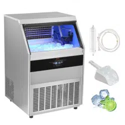
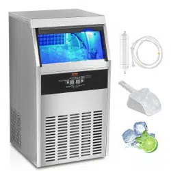
1. Features
L B series of ice maker, with a number of
patent control systems, simple operation,
accurate control, suitable for different water
quality conditions;
Key components apply internationally
well-known brands to ensure reliable work in
harsh environments;
Contact with water, use food grade plastic
material, shell stainless steel material to
ensure food safety and excellent rust-proof
performance.
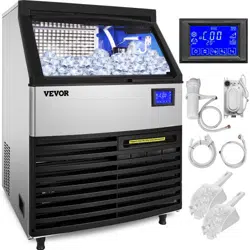
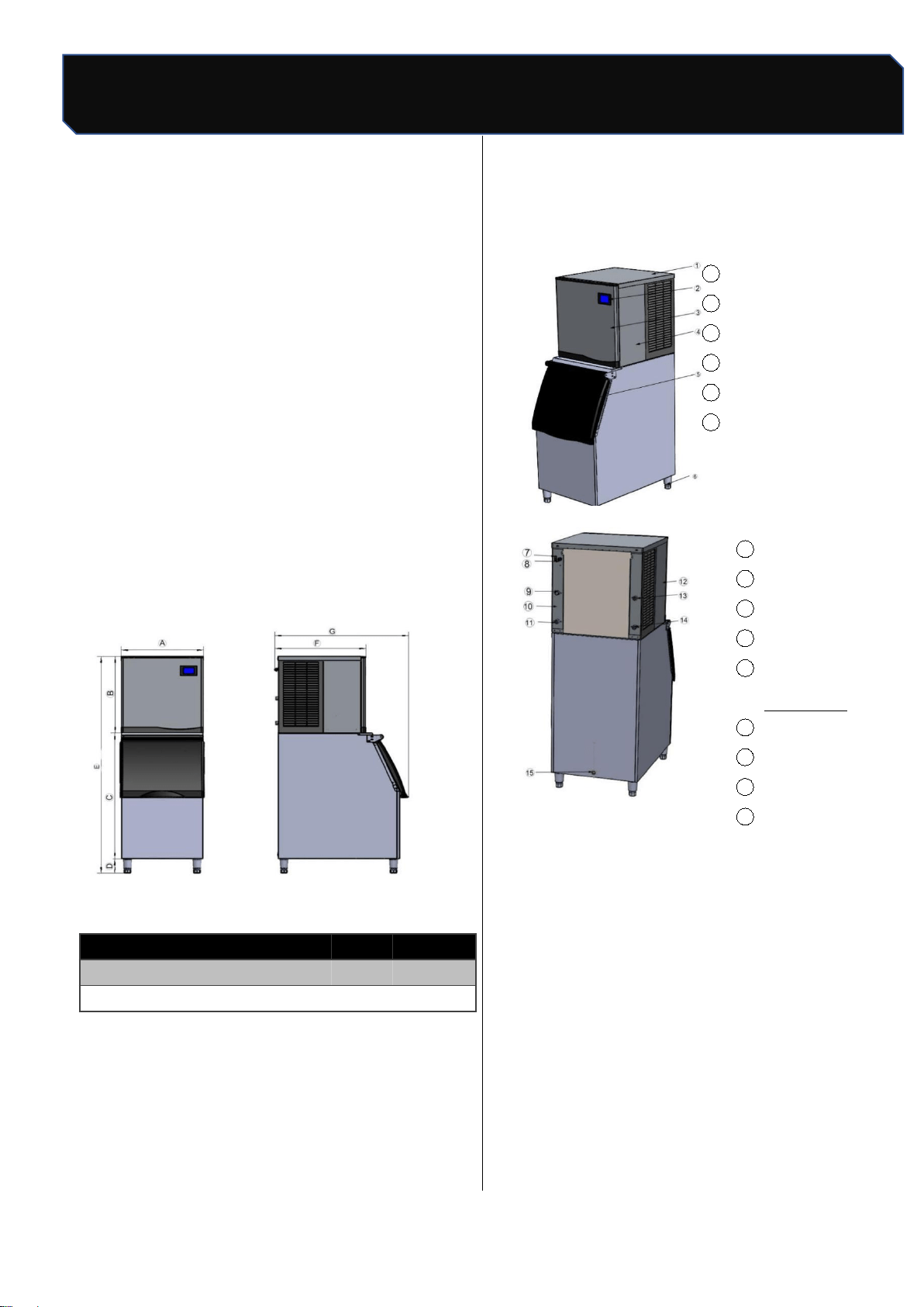
2.Apperance and
Size
2. Ice maker S
ize list (Unit:cm)
Appearance
1 Top panel
2
Touchscreen
3
Front panel
4
Right panel
5
Ice maker door
6
Adjustable foot
7
Power switch
8 Power cord
9
Water inlet valve
10
Back panel
11
Drainage
connection
12
Left panel
13 Condenser drain
14 Condenser inlet
15
Ice tank drain
A
B
C
D
E
F
G
LB300TA
57
62
92
16
170
70
91
LB400TA
57
62
92
16
170
70
91

Safety Tips
4 / 24
Number: JT190199989 Version Number: A1
Note: Subsequent versions of this specification are subject to change without prior notice. Thank you
Water supply/Purge
3. Unpackage
Before unpacking, check the anti-tilt sign is in
good condition, the outer packing of the
machine is in good condition, and the
machine model is consistent with what you
have purchased.;
Take out accessories and affiliated
documents, check for its consistency with
packing list;
If there is any discrepancy or damage, please
contact our company/distributor directly.
4. Installation location
This ice machine is not suitable for outdoor
use, installation position should not be near
the heat source or direct sunlight;
The normal working ambient temperature
should be ranged between 10°C~38°C, the
water temperature should be between 5°C~
32°C. If the ice-making machine operates
beyond the above normal temperature range
for a long time, its ice-making capacity may be
affected;
Ice makers should be placed near drinkable
water supply. It is recommended that distance
between ice makers be less than one meter;
Ice makers should be placed near drinkable
water supply. It is recommended that distance
between ice makers be less than one meterr;
Do not block the ventilation window of the ice
maker. There should be enough air
convection space around the ice maker;
The ice maker can not work at sub-zero
temperatures, to prevent supply line failures,
empty the ice maker when the temperature is
below zero(see “preparation for long-term
storage of ice maker”).
Warning
The ice maker is to be installed in
accordance with the Safety Standard for
Refrigeration Systems, ASHRAE 15 the ice
maker shall not be installed in corridors or
hallways of public buildings .
5. Leveling Adjustment
Screwing home four adjustable parts of the
legs first, and then screwing the legs into ice
maker bottom plate;
Moving ice maker to installation place.
Adjusting legs to ensure the ice maker is
leveling.
Note
Do not put hard object under legs for
leveling ice maker. Make sure the four legs
touching the ground steadily to prevent
vibration during operation.
Safety Tips
5 / 24
Number: JT190199989 Version Number: A1
Note: Subsequent versions of this specification are subject to change without prior notice. Thank you
Power supply
6. Water supply/Drainage
6.1 Water supply
With local potable water quality, determining if
a water treatment system is needed to
prevent sediment formation, filtering out
impurities and removing bleach smell;
Please install water supply pipe according to
below instruction:
Don't connect ice maker to hot water
pipe;
Water supply pressure range is 1bar~
5bar. Using water pressure regulator for
water supply pressure over rang.
Individual water faucet must be installed
for ice maker.
Warning
Ice makers must be connected to
potable water pipe
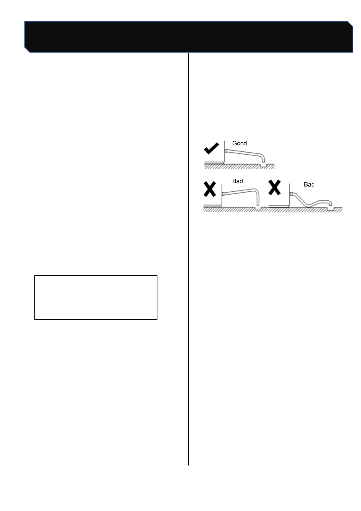
6.2 Drainage
When installing drain pipe, follow these
guidelines to be sure all purged water flowing
into gully drain:
The main gully drain capacity shall be enough
for all drain water:
Drain hose should be wrapped with
insulation material to prevent;
The drain hose of the water-cool
condenser and the drain hose of ice bin
should be placed separately;
About 2.5 centimeters drop needed for
each one meter additional drain hose and
must not be bent

Safety Tips
6 / 24
Number: JT190199989 Version Number: A1
Note: Subsequent versions of this specification are subject to change without prior notice. Thank you
Power supply
7. Power supply
The voltage, frequency and capacity of the
power supply shall be consistent with the
nameplate of the machine;
±10% fluctuation of rated power voltage is
allowed;
Separate circuit breakers must be installed for
the ice maker.
Warning
The power supply must be reliably
grounded and the wiring used must comply
with the laws and regulations of the country
and region where the ice maker is used.
8.Clean after Installation
After the ice maker is installed, clean the shell,
liner and ice scoop with a clean wet cloth or
sponge;
Warning
Banana oil, oxalic acid, hydrochloric a
cid, alcoholic liquids and other corrosive
detergents are strictly prohibited.
9. Check after installation
After the ice maker is installed, check against the
following information before operation.
Does ice maker place levelly?
Have you removed all the transportation
seals?
Are all the water and electricity connected
well?
Is the supply voltage consistent with the rated
voltage on the nameplate?
Is the ice maker properly grounded?
Are there adequate air Spaces around the ice
maker?
Is the ambient temperature of the ice maker
between 10°C and 38°C?
Does the water inlet temperature remain
between 5°C and 32°C?
Are the ice maker and refrigerator cleaned?
Safety Tips
7/24
Number: JT190199989 Version Number: A1
Note: Subsequent versions of this specification are subject to change without prior notice. Thank you
Ice Maker Operation
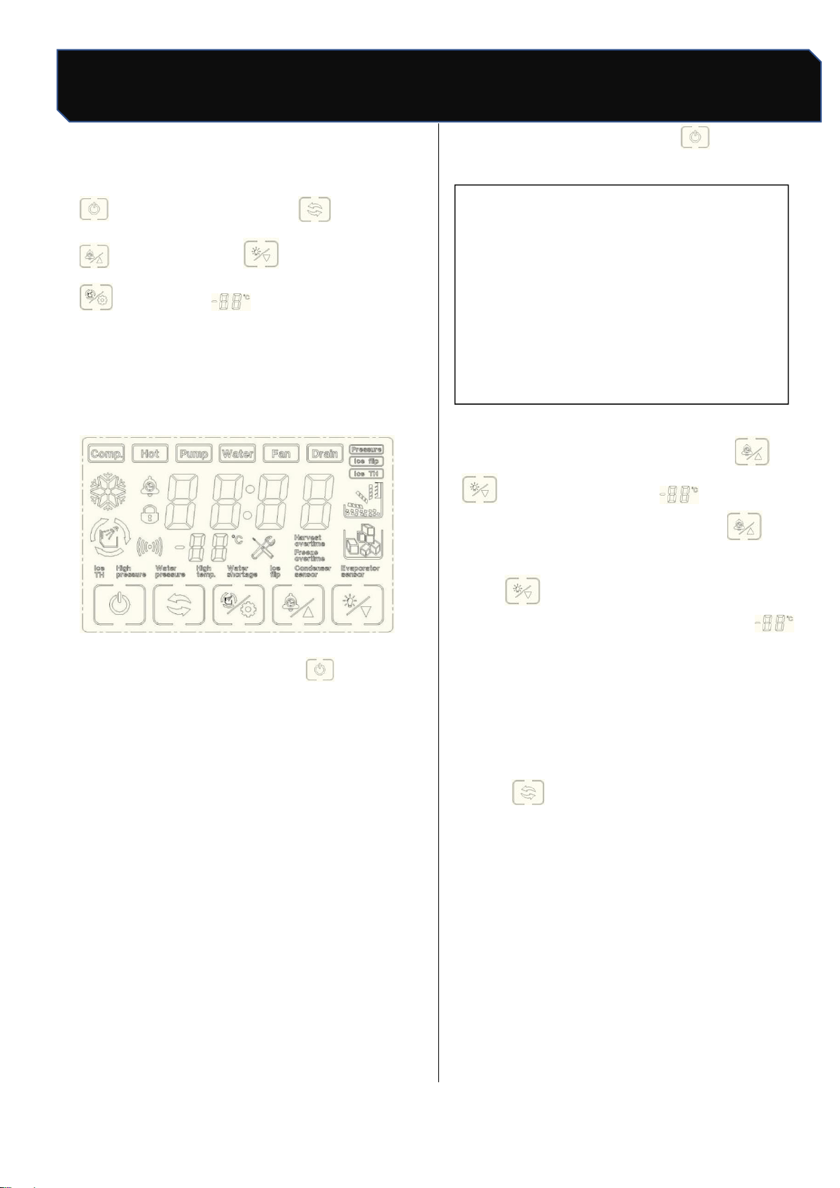
10. Operation of Ice Machine
"boot/ shutdown ": mode
"": Booking / Plus : Lighting/Subtraction
": Clean/Set " Count Display Area
10.1 Power on/off
Boot: connect water supply and drainage, plug in
power plug, press power switch, touch screen
start to light up;
Figure 1 Touch screen
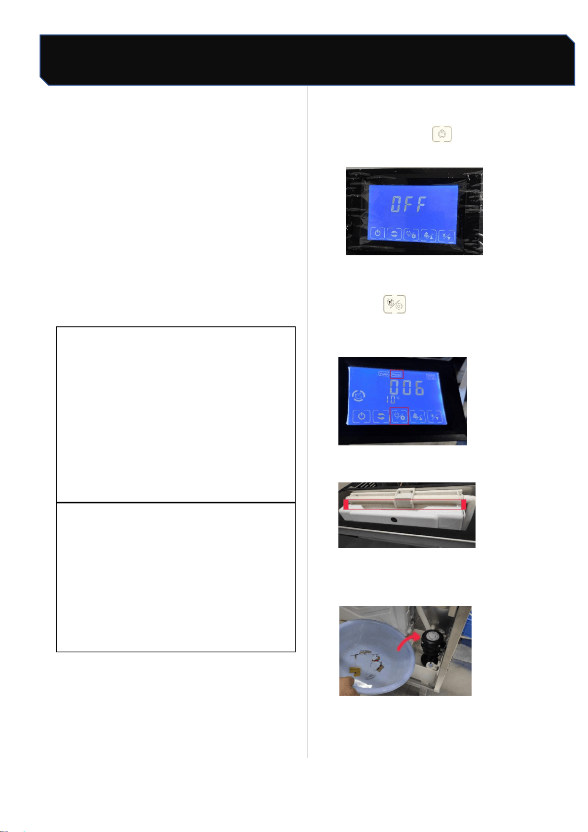
Power off: in ice making, press” "once, the ice
maker stops making ice (standby state), the screen
shows" OFF", press the power switch, then pull out
the power plug.
10.2 Ice making
a.After the ice maker is power on, the ice maker
automatically enters the ice making preparation
work. The preparation process includes water
pump start, hot valve open, compressor start, fan
start, etc. Under normal circumstances, after the
preparation work is finished, the ice maker start
automatic ice making, no need to do any more
operation until the ice machine stops making ice;
when the ice is removed, the ice machine begins
to make ice;
b. in standby state, press " ”once, start
making ice.
▲ attention
The ice maker has been tested and
debugged in the factory before shipment. The
new machine can make ice without any
debugging.
10.3 Ice thickness regulation function
In the ice-making state, press " "or
“ "can see the screen" ”count display
number start flashing, each press "can
increase the ice-making time for 1 minute, each
press” " can reduce the ice-making time for 1
minute; after adjustment, stop operation ," ”
the number no longer flashes, the ice thickness
setting is complete (note: before and after the ice
thickness adjustment, the ice maker has been
making ice);
10.4 Forced deicing
Press “ "to force deicing under ice-making
condition;

Safety Tips
8 / 24
Number: JT190199989 Version Number: A1
Note: Subsequent versions of this specification are subject to change without prior notice. Thank you
Ice Maker Operation
10.5 Manual cleaning
Press “ "in standby state, enter manual
cleaning state, cleaning icon flicker, water inlet
valve open, screen display start timing, about
15 minutes later, cleaning stop, start
drainage,30 s after drainage, enter automatic
rinsing stage, Clean for 3 minutes, drain for 30
s, and recycle for 5 times, the whole cleaning
process and the screen shows OFF", enter
standby state;
Note: if you need quick cleaning, you can not
wait 15 minutes to start drainage directly after 30 s,
enter the rinsing stage, rinse if you do not need to
cycle many times can press "stop rinsing, into
standby state;
10.6 Reserve ice making
Standby state (display "OFF""), the first time press
" enter time settings, each press "can
increase 10 minutes, each press" can
reduce 10 minutes; after setting up, press
once, the screen shows the countdown of the
set time, When the countdown is 00:00, the ice
maker begins to make ice.
10.7 Setup function
Standby state (screen display OFF), long press
"until the screen" OFF "disappear jump
into the parameter setting state, through
" ," to control the addition and subtraction
operation, set the state of light point"
switch the next setting, parameter switch
round, from the first parameter cycle again.
*" Setup function "is recommended to be operated
under the guidance of professionals and not to be
adjusted privately (see maintenance page for
details);

Safety Tips
9 / 24
Number: JT190199989 Version Number: A1
Note: Subsequent versions of this specification are subject to change without prior notice. Thank you
Working Process
11. Working process
11.1. Ice melting process:The display screen is all
bright after power on, and completely extinguished
after 1 second.Display C00 indicates that in the
influent state, until the water is full, it does not
enter the power-on delay state, the deicing
indicator lights shine, and the digital tube displays
the power-on delay time. The hot valve opens, the
press opens after 30 seconds, the hot valve
closes after 5 seconds, and deicing after 60
seconds.
11.2. Ice making process: during ice making, the
ice indicator light is on, the digital tube shows the
ice making time, and if the ice skating board is
opened continuously for more than 4 minutes, it
will turn to the ice full state. The compressor
continues to open, the heat valve closes, the fan is
controlled, the upper water valve is controlled 5
minutes before the start of ice making, more than
5 minutes later, and the pump opens after 90
seconds. When the water temperature is lower
than the setting temperature of ice making, start
timing, when the ice making time exceeds the set
time, the ice making ends.
11.3. Deicing process: after the ice making is
finished, it enters the deicing state, the deicing
indicator light is on, and the digital tube shows the
deicing time. Compressor continues to open, hot
valve open, pump, fan closed, upper water valve
controlled. The maximum time limit for deicing is 6
minutes. If the ice is not taken off for 5 minutes,
open the pump for 1 minute. If the ice is still not
taken off, turn to ice making, if the ice is not closed,
turn to ice full. Three times in a row for more than
6 minutes, turn to deicing timeout stop.
11.4. Ice full detection: after the ice is removed, if
the ice in the refrigerator is not full, enter the ice
making state and carry out a new cycle. If the
refrigerator is full of ice, enter the ice full stop state,
ice full indicator light.Water pump, press, hot valve,
upper valve, fan all closed. If the ice is removed,
within 180 seconds of the press closing, the ice full
indicator lights shine. If the pressure mechanism is
closed for 180 seconds, turn to power up for a new
cycle. If the ice is not taken away, it is always in a
state of ice.
12. Operational inspections
Make sure the tap is open.
Make sure the inlet valve is open.
The ice maker has been powered on.
Check all pipes and fittings to ensure no
leakage.
▲ attention
The ice maker has been tested and debugged
in the factory before shipment. The new
machine does not need any debugging. In
order to ensure the normal operation of the
ice maker, operation inspection is required
under the following circumstances;
Initial initiation
Restart after long downtime
After cleaning and disinfection
Safety Tips
10 / 24
Number: JT190199989 Version Number: A1
Note: Subsequent versions of this specification are subject to change without prior notice. Thank you
Check before operation
13. Routine cleaning
▲ attention
It is strictly forbidden to wash the ice
machine with water sprayer. Do not use
any alcoholic liquid to clean or disinfect the
ice maker, otherwise it may cause cracks in
plastic parts;
Remove the roof and back panel, and
should be removed by maintenance
personnel with relevant knowledge;
Do not wash plastic parts in water or
dishwasher above 40℃ temperature to
avoid damage to parts.
Environmental cleaning: often clean the ice maker
to keep the environment clean and make the
equipment run efficiently.
Shell cleaning: clean the ice machine with
sponge dipped in neutral cleaning liquid and
dry with clean soft cloth. Use stainless steel
cleaners if necessary.
Air filter cleaning: filter can filter dirt or dust in
the air to prevent condenser clogging. If the
filter is blocked, the performance of the ice
maker will decline.It is recommended that air
filters be cleaned once or twice a month:
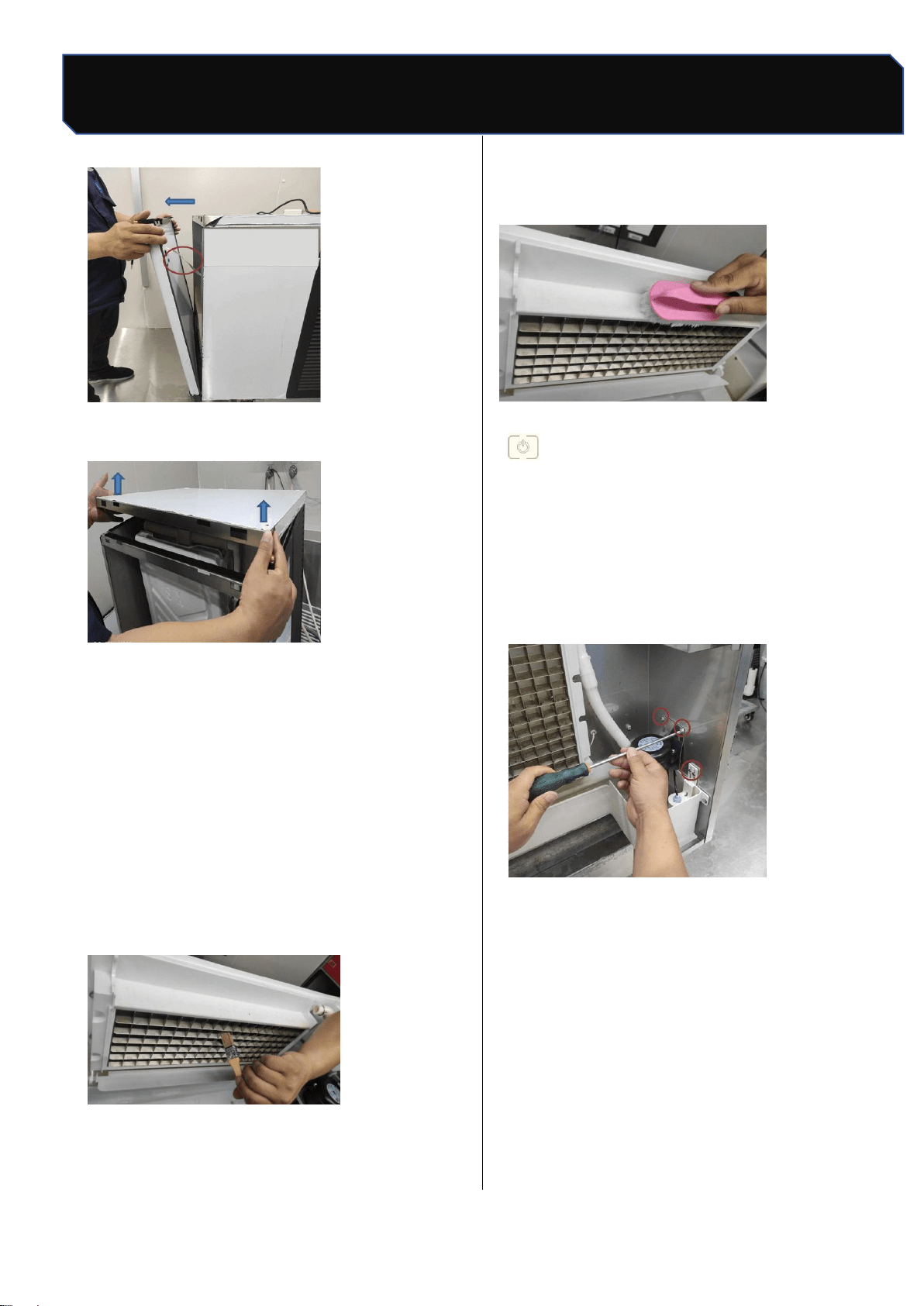
13.1 Shell removal
★
important
If necessary, it is not recommended to remove
the top cover plate, please have the relevant
knowledge or under the guidance of
professionals.
If you need to remove machine
cleaning, please follow the following
method
Remove front panel and top panel of ice
maker There is a plastic lock (or screw)
between the top cover plate and the front
panel of the ice maker. Please use a word
screwdriver to press down and gently until the
lock is ejected; otherwise, remove the screw
with a cross screwdriver;
Move the front panel gently in your direction
until you see the connection stop moving,
unplug the connection, and remove the front
panel completely
Safety Tips
11 / 24
Number: JT190199989 Version Number: A1
Note: Subsequent versions of this specification are subject to change without prior notice. Thank you
Cleaning and Disinfection
And then gently lift the top cover can be the top
cover
13.2. Evaporator cleaning
Remove before cleaning as detailed in
14.3 parts removal / installation process,
The following cleaning process can be
removed
Scrub the evaporator surface with a brush
or sponge dipped in scale remover or vinegar;
Use nylon brush to dip in scale remover or
vinegar to wash plastic parts around
evaporator;
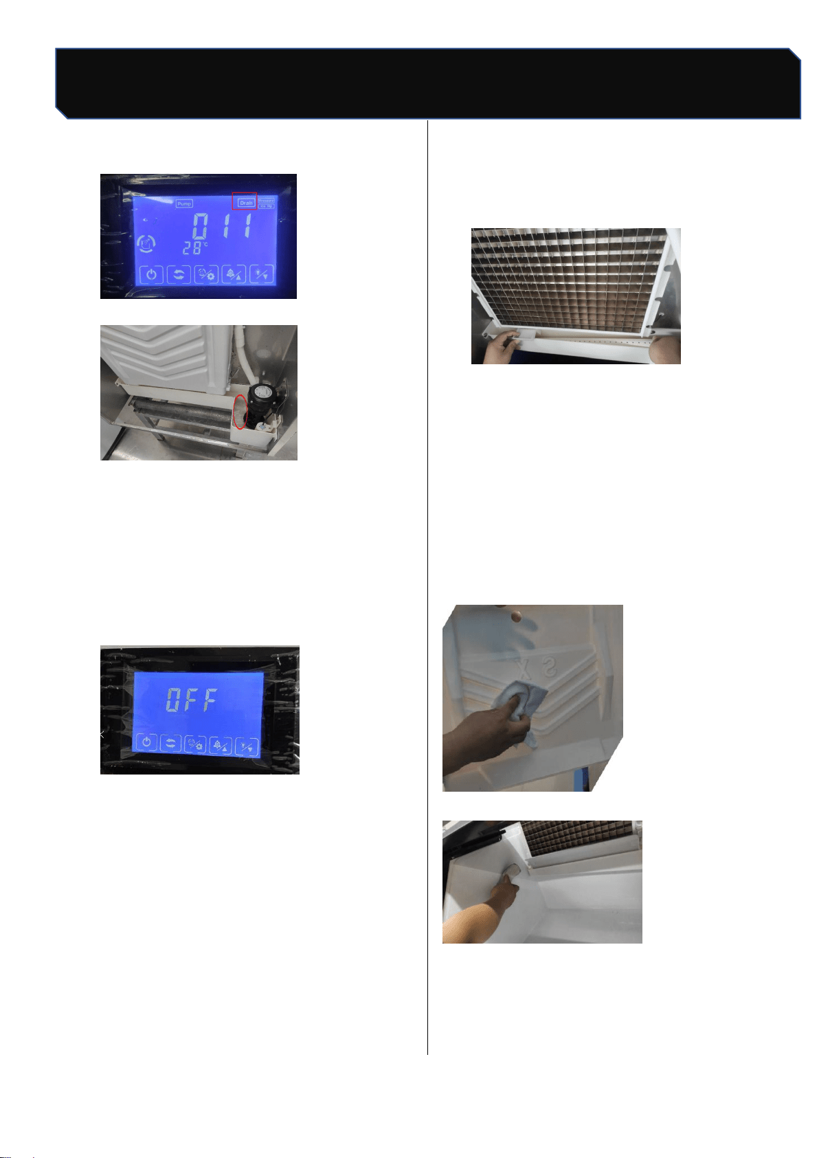
13.3 Flume cleaning
OFF", unplug the power plug, remove the
two screws on the water pump board and the
two screws on the float cover with a
screwdriver, remove the clamps, remove the
upper water pipe, water pump and float
connector, and remove the pump and float
clean;
Safety Tips
12 / 24
Number: JT190199989 Version Number: A1
Note: Subsequent versions of this specification are subject to change without prior notice. Thank you
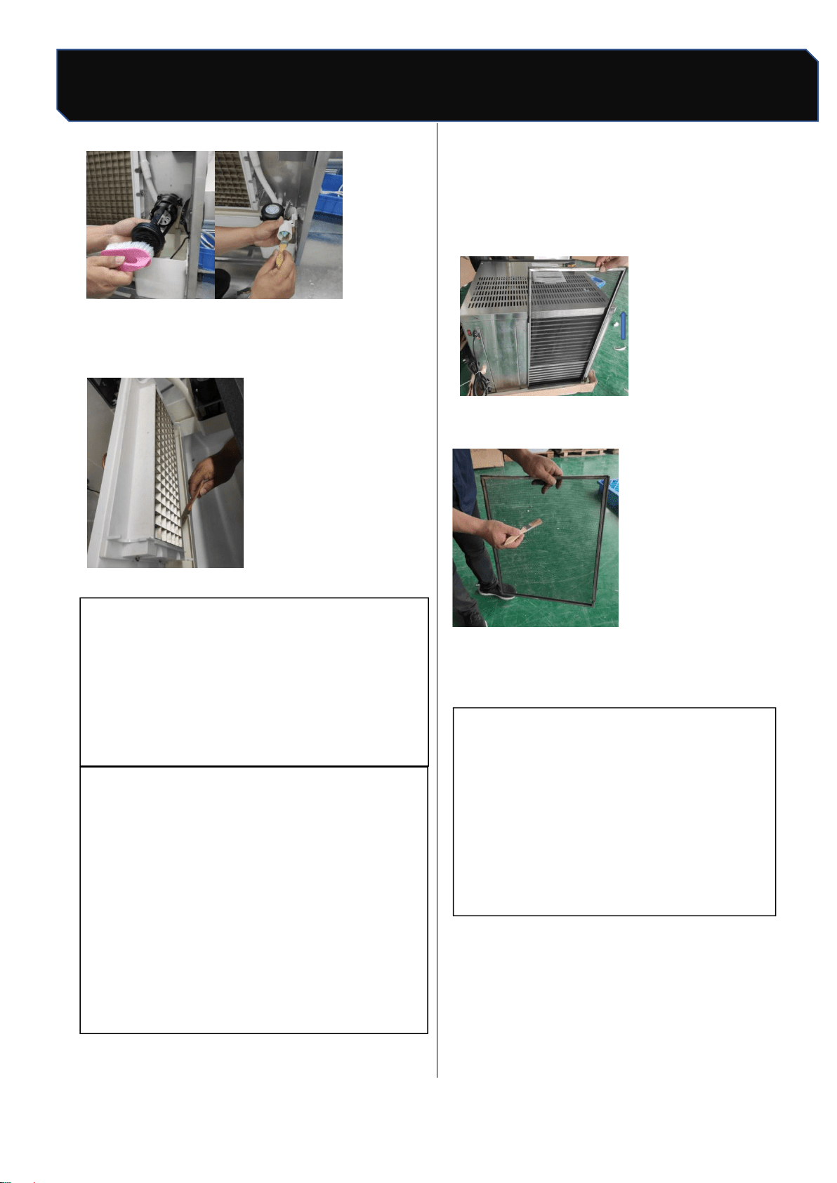
Cleaning and disinfection
Use soft ground materials such as brush or
sponge to dip in scale remover or vinegar to
scrub the sink.
13.4 Condenser cleaning
Warning
Clean condenser, must disconnect ice
machine power supply. Condenser edge sharp,
clean carefully cut.
★ important
The dirty condenser will block the
circulation of air, cause the operating
temperature of the ice maker to be too high,
reduce the amount of ice making and shorten
the service life of the parts.
It is recommended that the condenser be
cleaned every six months, following the
following steps:
Remove the filter from the back of the ice
maker
Use a brush to remove dust and dirt from the
filter;
Brush condenser fin dust with nylon brush
along fin direction;
★ important
After cleaning, please install back the
top cover plate, back plate, correct
installation cooperation.
Safety Tips
13 / 24
Number: JT190199989 Version Number: A1
Note: Subsequent versions of this specification are subject to change without prior notice. Thank you
Cleaning and disinfection
14. Cleaning and disinfection
In order to make the operation of ice maker
stable and efficient, the user has the responsibility
to operate according to the requirements of
cleaning and disinfection (cleaning and
disinfection operation, not within the warranty
clause). If the ice maker needs frequent cleaning
and disinfection, check that the water source
is suitable, that the environment is clean or that
inappropriate water filters are used.
▲
attention
Do not mix the disinfectant with the
cleaning solution.
Do not clean the evaporator surface with
sharp objects.
It is recommended that this process be
implemented at least once within 3
months.
Warning
Wear protective equipment such as
rubber gloves, masks and protective
glasses before cleaning and disinfection.
Removal and installation of cleaned parts
must be carried out in case of power
failure.
ice cubes during cleaning and disinfection
14.1 Cleaning process
1. Open the front panel of the ice maker and
check that the evaporator is making ice. If you
are making ice, you can execute the forced
deicing program (see "10.4 forced deicing
"above) so that the ice maker stops making
ice, press the" key "in standby state,
and the screen displays" OFF";" on the screen
2.
Remove all ice from the refrigerator with an ice
shovel;
3.
Press the "button ," the ice maker enters
the cleaning phase, the inlet valve opens, the
screen displays start timing,
When running water on the evaporator,
4.
Add 2 packs of cleaning agent (KAY
DELIMER ,56.7g/ pack) or mixed detergent to
the ice maker sink,
The water in the evaporator has been cleaned by
circulation for about 15 minutes
Safety Tips
14 / 24
Number: JT190199989 Version Number: A1
Note: Subsequent versions of this specification are subject to change without prior notice. Thank you
Cleaning and disinfection
Stop, start draining
30 s after completion of drainage;
Enter the automatic rinsing phase, clean for 3
minutes before draining
30 s, After 5 cycles of rinsing process, the whole
cleaning process is completed
Beam, screen display "OFF", into standby state,
the whole process
It takes about 37 minutes;
5.
Unplug the power.
6. Remove flow pipe, water retaining plate, take
out water pump, float ball, ice shovel (removal
method refer to parts removal / installation
process).
7.
Mix 8 liters of warm water (45~50℃) and 4
packets of cleaning agent (KAY
DELIMER ,56.7g/ package) into cleaning
liquid (the amount of cleaning liquid needs to
be adjusted appropriately).
8.
Soak the parts in the cleaning solution for more
than 5 minutes (if the scale is heavy, it is
recommended to soak for more than 10
minutes).
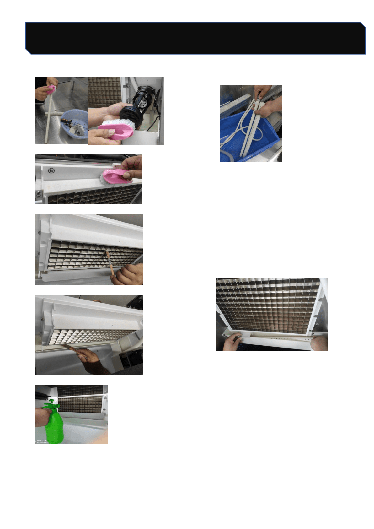
9.
While soaking parts, wipe the surface of parts
in contact with water and ice with nylon brush
or soft cloth dipping cleaning liquid, such as
evaporator ice grid, ice baffle, ice storage
bucket, etc .(the dead corner can be dipped in
cleaning agent wet rag wrapped disposable
chopsticks cleaning). Rinse with clean water
(5 times).
Scrub the ice shield
Wash the refrigerator
Safety Tips
15 / 24
Number: JT190199989 Version Number: A1
Note: Subsequent versions of this specification are subject to change without prior notice. Thank you
Cleaning and disinfection
Brush water pipe mandrel brush pump bottom
Plastic parts around brush steam
Brush evaporator
Brush sink
Flush evaporator
Flush hose and mandrel
10.
Remove the soaked parts and rinse them with
clean water (5 times).
14.2 Disinfection process
1. Mix 8 liters of warm water (45~50℃) and 2
packs of disinfectant (KAY5,28.4g/ package)
into disinfectant solution (the amount of
disinfectant is adjusted according to the
amount of cleaning parts needed).
2. Soak the cleaned parts in the disinfectant.
While soaking the parts, spray the disinfectant
evenly and completely on the surface of the
parts in contact with the ice, such as evaporator
ice grid, ice baffle, ice storage bucket, etc .(the
dead corner can be wrapped with disinfectant
wet rag wrapped in disposable chopsticks
cleaning).
Safety Tips
16 /24
Number: JT190199989 Version Number: A1
Note: Subsequent versions of this specification are subject to change without prior notice. Thank you
Cleaning and disinfection
After 20 minutes, remove the soaked parts and
rinse them with clean water.Install the removed
parts back to their original position (installation
method refers to 14.3 parts removal /
installation process) strictly follow the
requirements.
3. 1 liter of water and 1/2 package of disinfectant
(KAY5,28.4g/ package) were used to form
disinfectant.
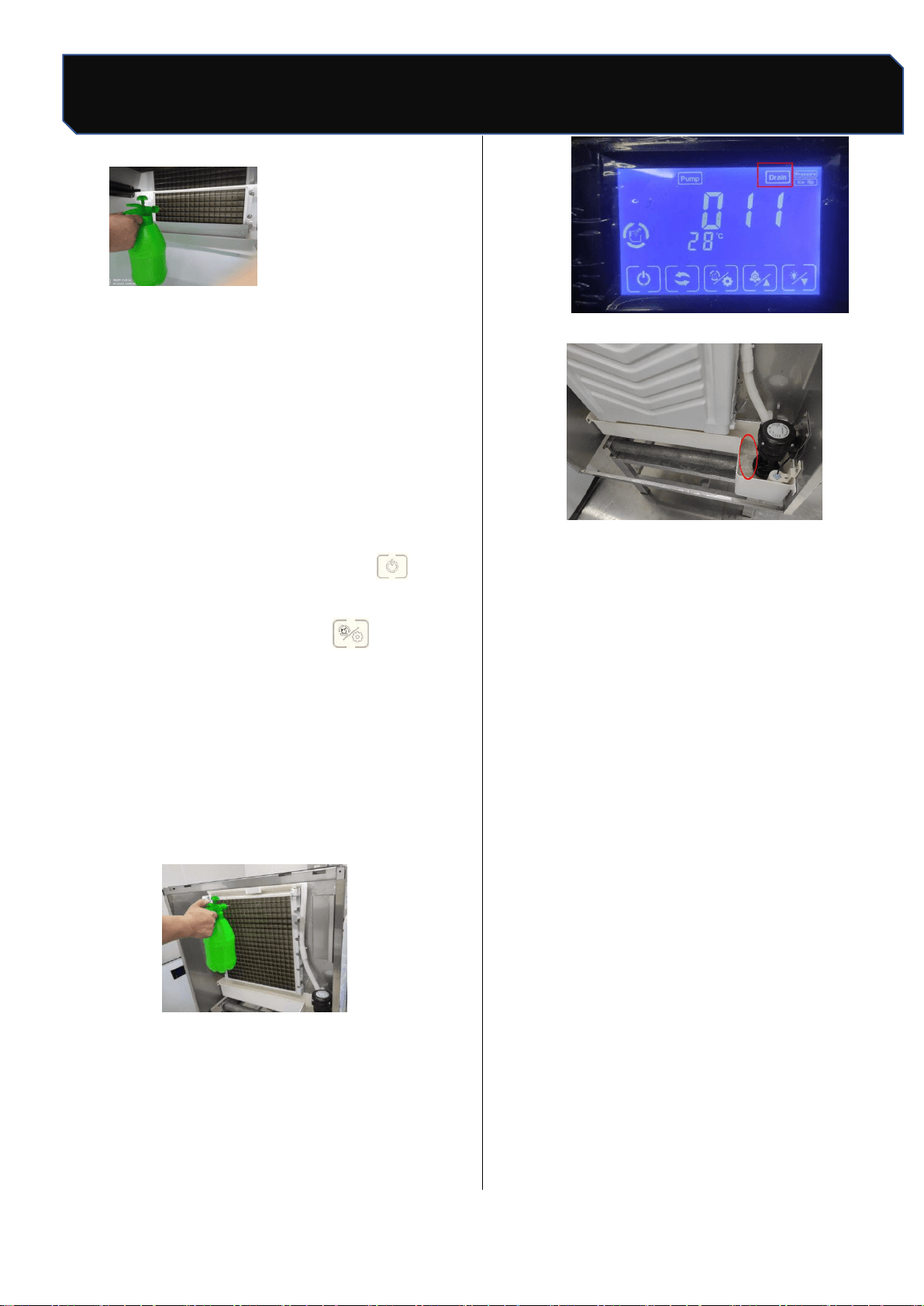
4. plug in the power plug, then press " "key to
make the ice maker in standby state, the
screen shows "OFF"; press" key, the ice
maker enters the cleaning stage, the inlet
valve opens, the screen display starts to time,
when the evaporator begins to flow water, add
the equipped disinfectant to the ice maker
sink, and at the same time, use the outer
surface of the spray with disinfectant
The water between the tank and the
evaporator is cleaned continuously. After
about 15 minutes, the cleaning stops
and the evaporator is flushed
30 s after completion of drainage;
5. Enter the automatic rinsing phase, clean for 3
minutes,
After another 30 s, of water rinsing,
Rinse again with purified water for 3
times, the whole cleaning process
At the end, the screen shows "OFF", for
about 37 minutes
After the cleaning process is over, the
screen displays "OFF", to enter
Machine status, then unplug;
6. Note: start making ice after cleaning and
disinfection
The ice is discarded and not eaten.
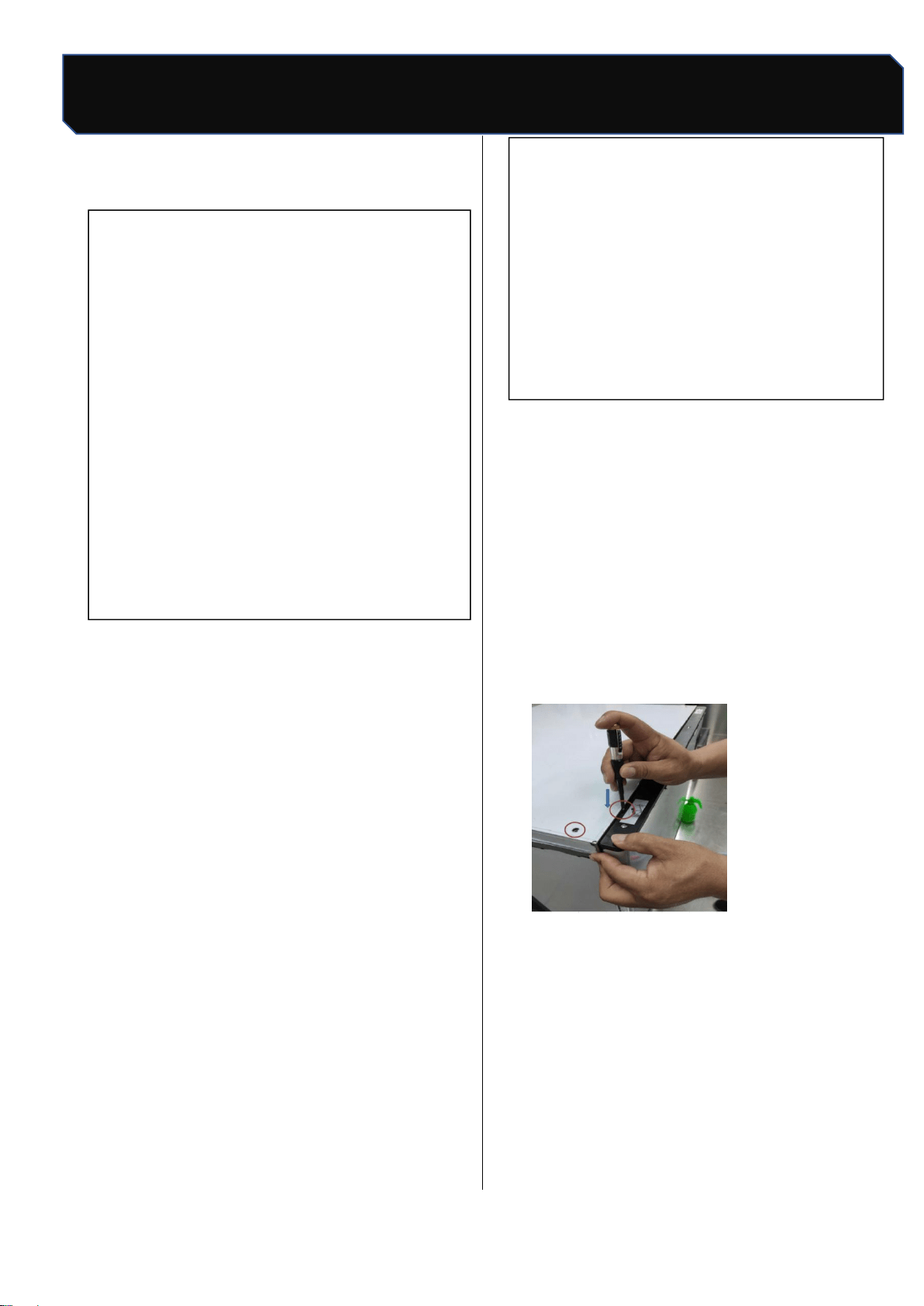
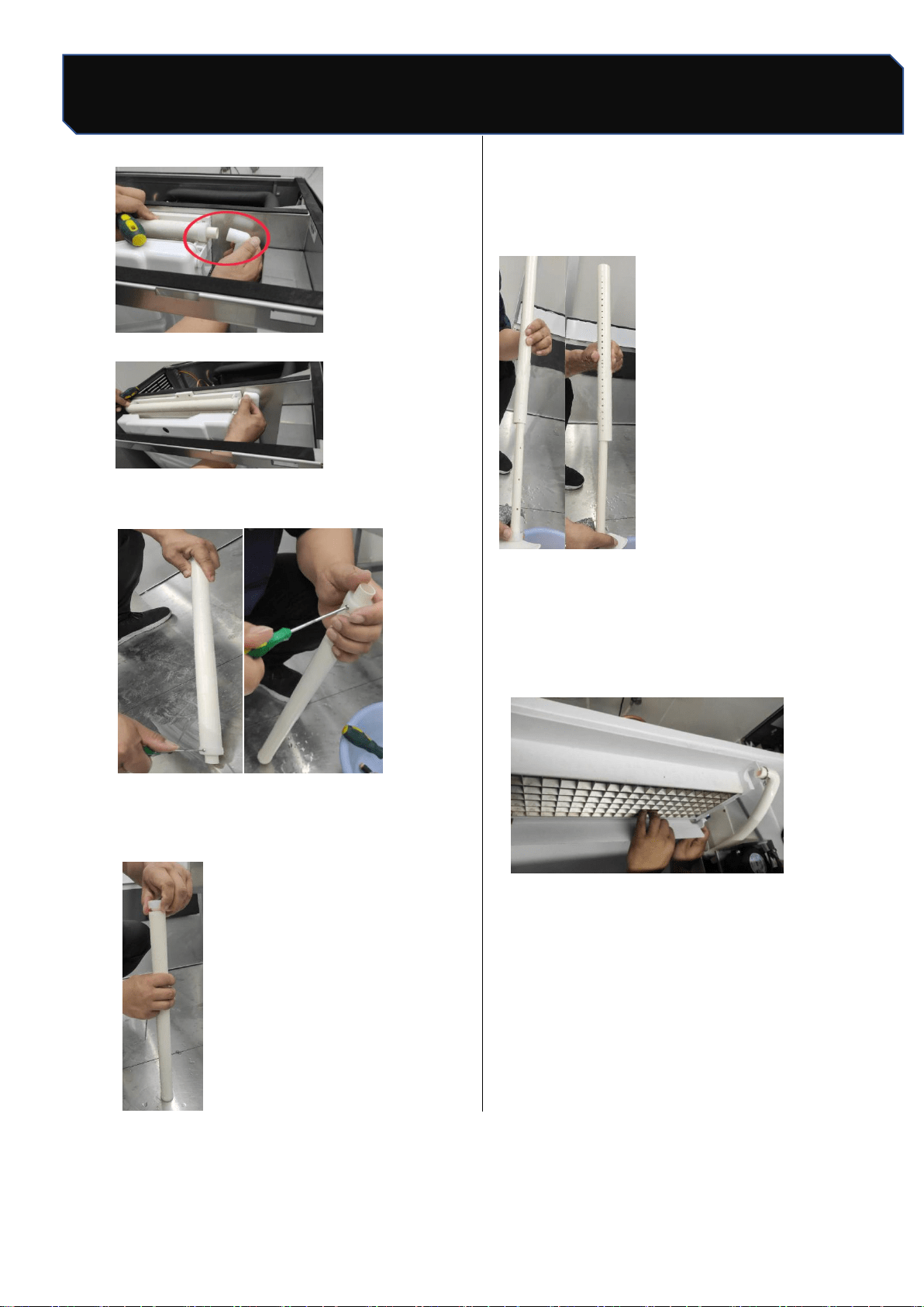
14.3 Removal/installation process of parts
a.When removing the pipe, remove "pull out"
clamps "and" upper pipes "(as shown):
Pull out the hose
Safety Tips
17 / 24
Number: JT190199989 Version Number: A1
Note: Subsequent versions of this specification are subject to change without prior notice. Thank you
Cleaning and disinfection
Unplug pipe
b.Remove two screws
c.
Spin out the plastic cover and remove the
plastic mandrel
Note: when the pipe is assembled, the pipe hole
position and mandrel hole position direction
should be opposite, must not be the same
direction, the correct diagram is as follows:
d.Disassemble and assemble the baffle: grasp
the middle position of the baffle and use a flat
screwdriver to force from one side to the
other until one side of the baffle is removed
from the pin hole.

Safety Tips
18 / 24
Number: JT190199989 Version Number: A1
Note: Subsequent versions of this specification are subject to change without prior notice. Thank you
Maintenance
15. Removal from service /
Winterization
Note
If water is left in the machine in an
environment below 0°C, it may cause serious
damage to the machine parts. This fault is not
covered by warranty
Special protection measures are
required if the ice maker is out of service for
a long period of time or exposed to an
environment of 0°C or less. Follow these
steps below:
Disconnect the power of the ice maker.
Disconnect the water supply to the ice
maker.
Empty the sink.
Remove water inlet hose and drain it
from the water inlet.
Ensure that there is no water residue in
the inlet, drain and distribution pipes..
16. Maintenance
Warning
Component parts shall be replaced with
like components and that servicing shall be
done by factory authorized service
personnel, so as to minimize the risk of
possible ignition due to incorrect parts or
improper service.
Before applying for repair, please consider the
following aspects in order to quickly identify and
improve the efficiency of machine recovery .
a). Whether the water supply is normally,
including faucets open, inlet valve not
blocked, and water pressure is in 1bar~5bar.
b). Whether the power supply is normal,
including voltage is in ±10% of rated voltage,
power switch is connected, the fuse is not
burnt out and whether the plug is fixed well
c). Whether the ambient temperature is too
high or too low (the operating temperature
range of the ice maker is 10°C~38°C),
whether the water temperature is too high or
too low (the water temperature range is
5°C~32°C).
d). Whether the ice bin is full of ice and can
work after ice take away.
Write down the number of the machine and call
the toll-free phone number labeled with the
service label or your service provider
Safety Tips
19 / 24
Number: JT190199989 Version Number: A1
Note: Subsequent versions of this specification are subject to change without prior notice. Thank you
Circuit diagram
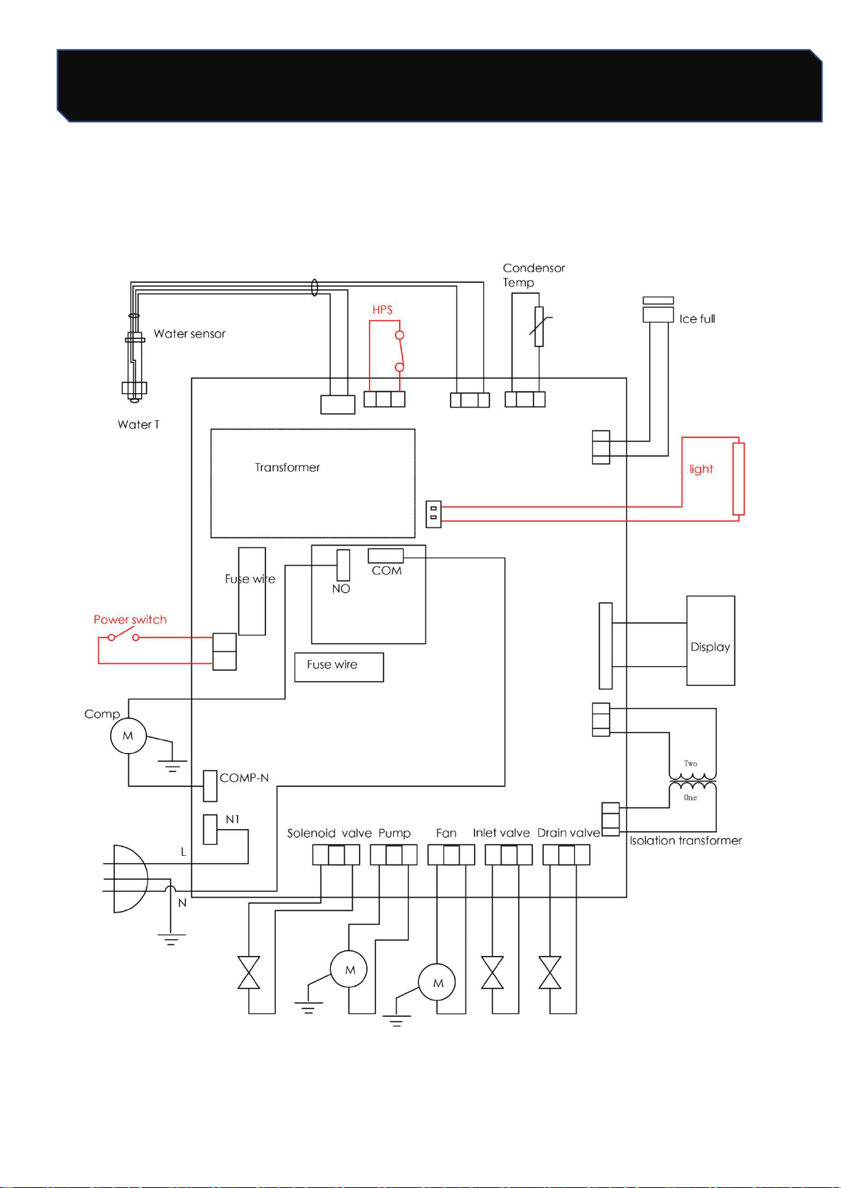
17. Circuit diagram
Safety Tips
20 / 24
Number: JT190199989 Version Number: A1
Note: Subsequent versions of this specification are subject to change without prior notice. Thank you
Assembly system
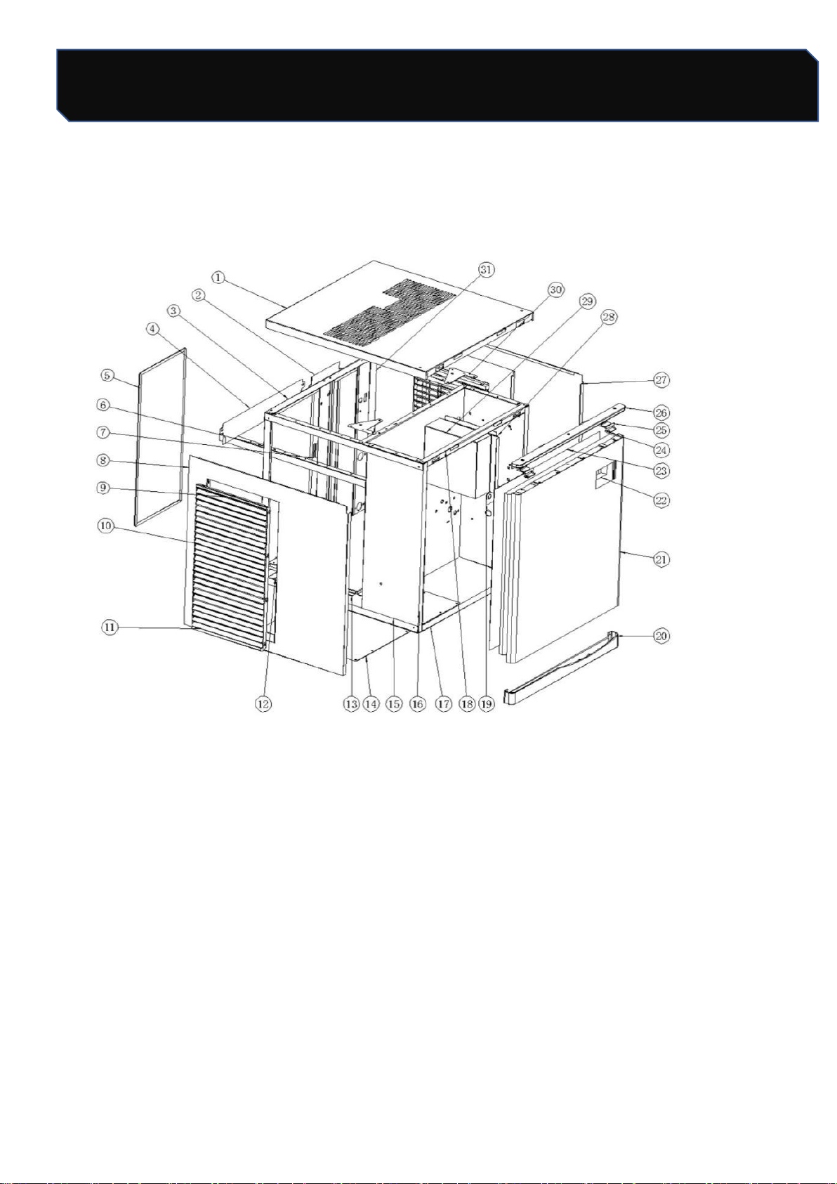
18. Explosive maps
Assembly system
Safety Tips
21 / 24
Number: JT190199989 Version Number: A1
Note: Subsequent versions of this specification are subject to change without prior notice. Thank you
Assembly system
NO。
Figure 1
LB300TA
LB400TA
NO。
Figure 1
LB300TA
LB400TA
1
Top panel
1
1
17
Front lower
beam
1
1
2
Backward back
panel
1
1
18
Front beam
1
1
3
Rear beam
1
1
19
High pressure
valve holder
1
1
4
Windscreen on
condenser
/
/
20
Lower door
1
1
5
Dustproof net
1
1
21
Front panel
1
1
6
Left vertical
bracket
1
1
22
Foam board
1
1
7
Middle vertical
bracket
1
1
23
ABS board
1
1
8
Left panel
1
1
24
Spring Plate
2
2
9
Card bar
2
2
25
Door clasp
2
2
10
Main body of wind
window
6
6
26
Door to door
1
1
11
Lower Card
2
2
27
Right panel
1
1
12
Back lower beam
1
1
28
Electrical Box
Installation
Guide
2
2
13
Floor
1
1
29
Electrical box
1
1
14
Bottom seal plate
1
1
30
Rack triangle
block
2
2
15
Longitudinal
beam
4
4
31
Right vertical
bracket
1
1
16
Ice sheet
1
1
Safety Tips
22 / 24
Number: JT190199989 Version Number: A1
Note: Subsequent versions of this specification are subject to change without prior notice. Thank you
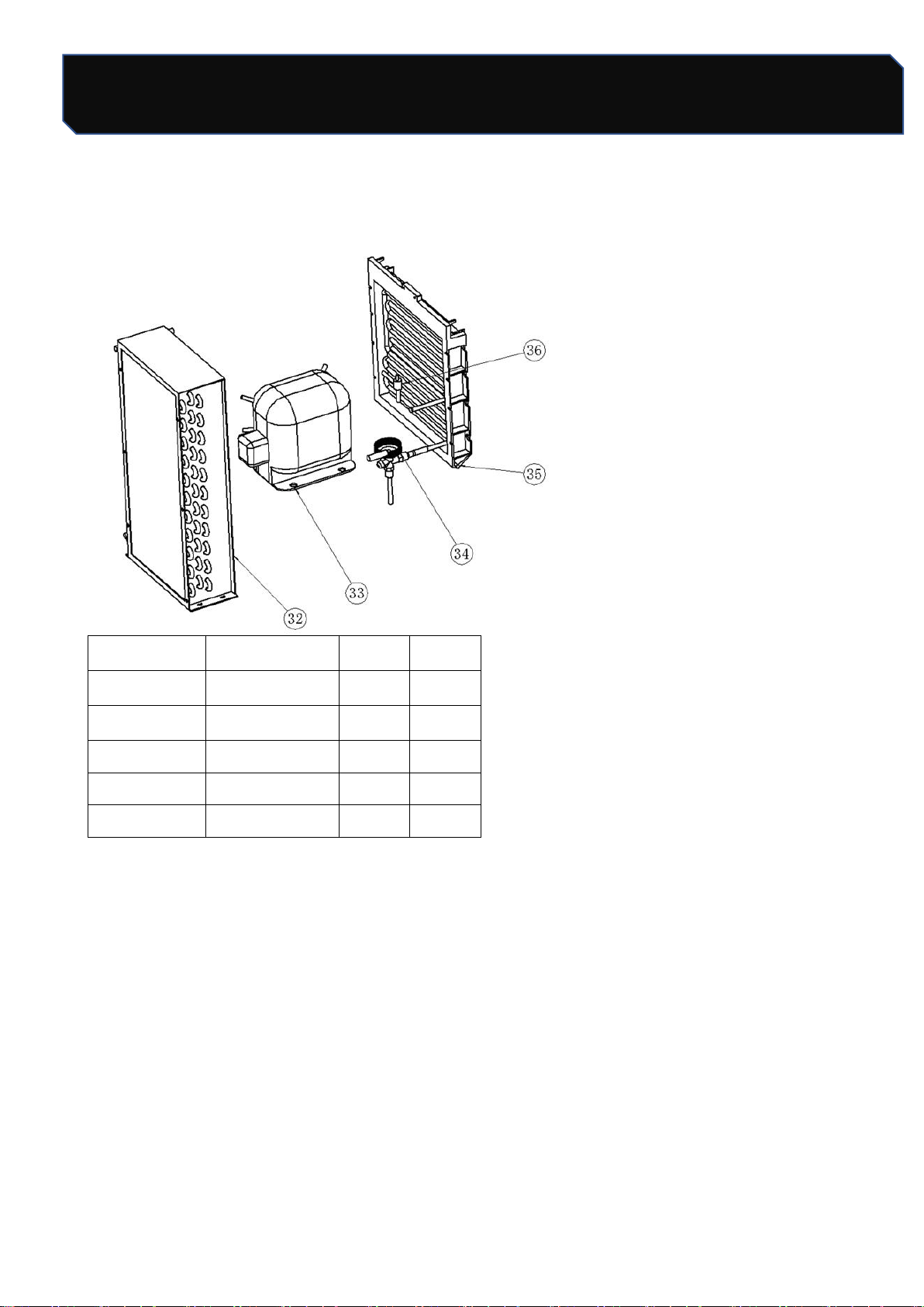
Refrigeration system
Refrigeration system
Serial number
Figure 1
LB300TA
LB400TA
32
Condenser
1
1
33
Compressor
1
1
34
Expansion valve
1
1
35
Ice
1
1
36
Solenoid valve
1
1
Safety Tips
23 / 24
Number: JT190199989 Version Number: A1
Note: Subsequent versions of this specification are subject to change without prior notice. Thank you
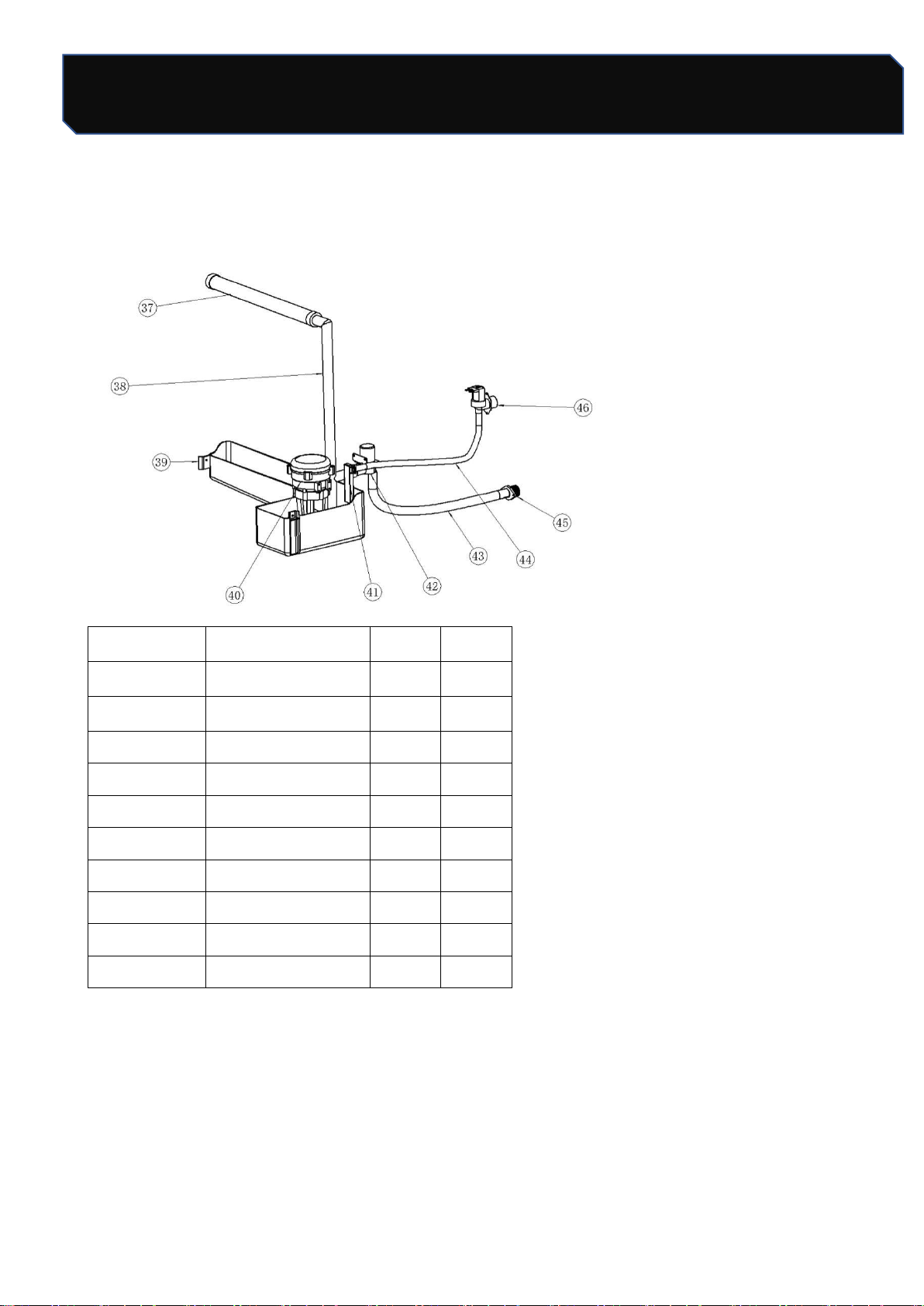
Water circulation system
Water circulation system
Serial number
Figure 1
LB300TA
LB400TA
37
Flow pipe
1
1
38
Water mains
1
1
39
Flats
1
1
40
Pump
1
1
41
Feed pipe joints
1
1
42
Drain valve
1
1
43
Drainage
1
1
44
Water intake
1
1
45
Drainage connection
1
1
46
Water intake valve
1
1
Safety Tips
24 / 24
Number: JT190199989 Version Number: A1
Note: Subsequent versions of this specification are subject to change without prior notice. Thank you
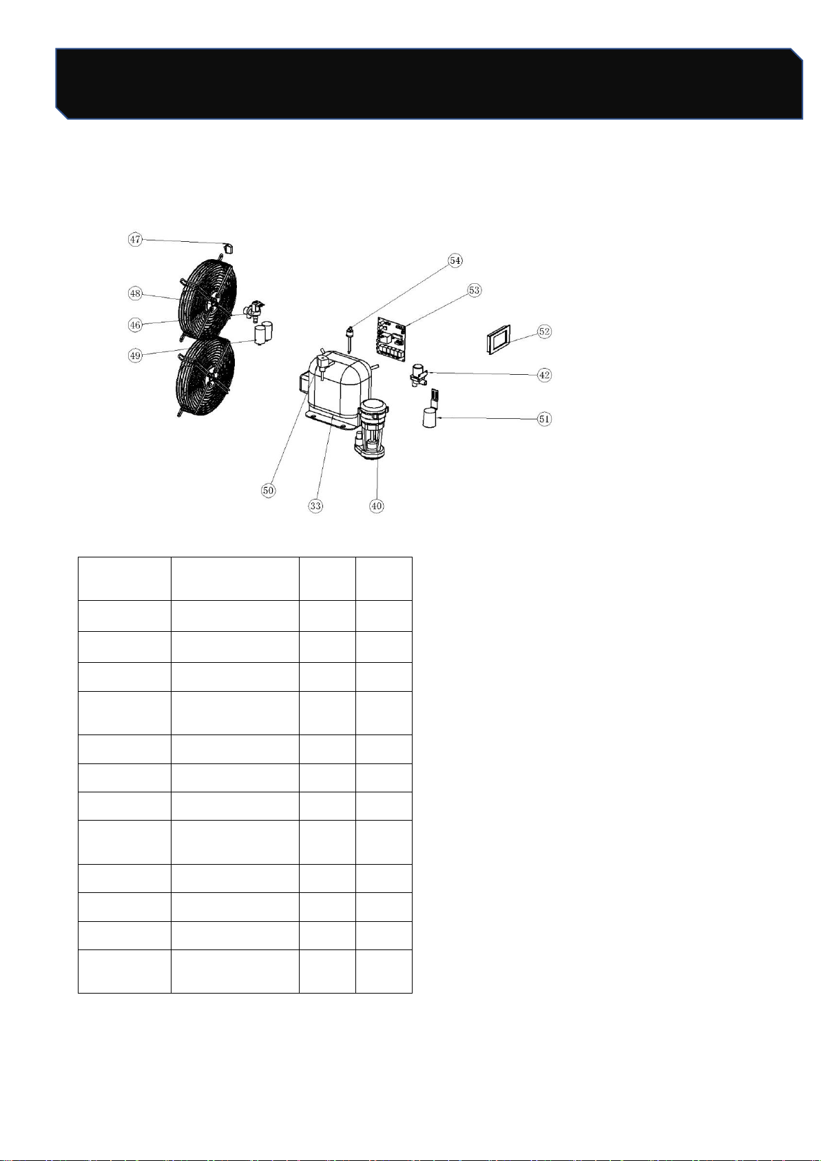
Electric control system
Electric control system
Serial
number
Figure 1
LB300T
A
LB400T
A
33
Compressor
1
1
40
Pump
1
1
42
Drain valve
1
1
46
Water intake
valve
1
1
47
Power switch
1
1
48
Fan
2
2
49
Fan capacitance
2
2
50
solenoid valve
coil
1
1
51
Float Cover
1
1
52
Display
1
1
53
Circuit Board
1
1
54
High voltage
switch
1
1