Loading ...
Loading ...
Loading ...
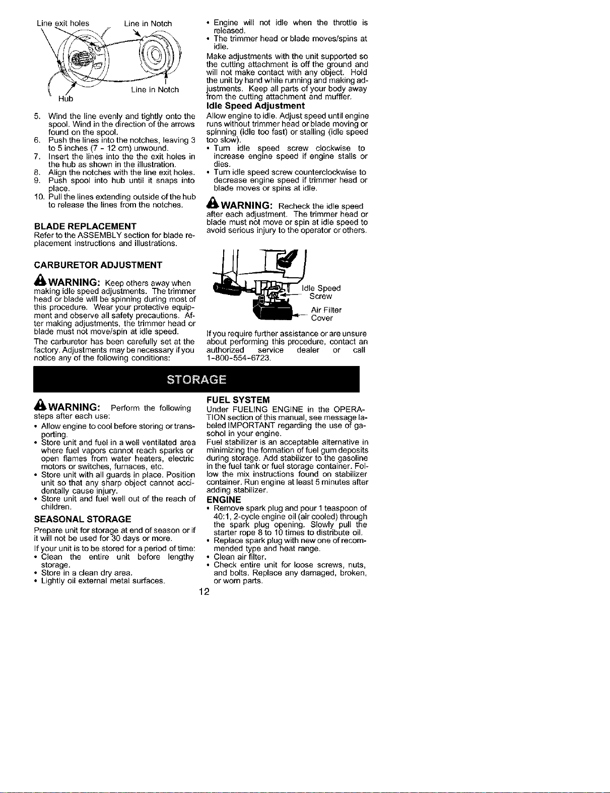
Line exit holes Line in Notch
\
Line in Notch
Hub
5. Wind the line evenly and tightly onto the
spool. Wind in the direction of the arrows
found on the spool.
6. Push the lines into the notches, leaving 3
to 5 inches (7 - 12 cm) unwound.
7. Insert the lines into the the exit holes in
the hub as shown in the illustration.
8. Align the notches with the line exit holes.
9. Push spool into hub until it snaps into
place.
10. Pull the lines extending outside of the hub
to release the lines from the notches.
BLADE REPLACEMENT
Refer to the ASSEMBLY section for blade re-
placement instructions and illustrations.
CARBURETOR ADJUSTMENT
WARNING: Keep others away when
making idle speed adjustments. The trimmer
head or blade will be spinning during most of
this procedure. Wear your protective equip-
ment and observe all safety precautions. Af-
ter making adjustments, the trimmer head or
blade must not move/spin at idle speed.
The carburetor has been carefully set at the
factory. Adjustments may be necessary if you
notice any of the following conditions:
• Engine will not idle when the throttle is
released.
• The trimmer head or blade moves/spins at
idle.
Make adjustments with the unit supported so
the cutting attachment is off the ground and
will not make contact with any object. Hold
the unit by hand while running and making ad-
iustments. Keep all parts of your body away
rom the cutting attachment and muffler.
Idle Speed Adjustment
Allow engine to idle. Adjust speed until engine
runs without trimmer head or blade moving or
spinning (idle too fast or stalling (idle speed
too slow).
• Turn idle speed screw clockwise to
increase engine speed if engine stalls or
dies.
• Turn idle speed screw counterclockwise to
decrease engine speed if trimmer head or
blade moves or spins at idle.
_ WARNING: Recheck the idle speed
after each adjustment. The trimmer head or
blade must not move or spin at idle speed to
avoid serious injury to the operator or others.
_dle Speed
Screw
Air Filter
_'_ Cover
Ifyou require further assistance orare unsure
about performing this procedure, contact an
authorized service dealer or call
1-800-554-6723.
I_WARNINL_: Perform the following
steps after each use:
• Allow engine to cool before storing or trans-
porting.
• Store unit and fuel in a well ventilated area
where fuel vapors cannot reach sparks or
open flames from water heaters, electric
motors or switches, furnaces, etc.
• Store unit with all guards in place. Position
unit so that any sharp object cannot acci-
dentally cause injury.
• Store unit and fuel well out of the reach of
children.
SEASONAL STORAGE
Prepare unit for storage at end of season or if
it will not be used for 30 days or more.
If your unit is to be stored for a period of time:
• Clean the entire unit before lengthy
storage.
• Store in a clean dry area.
• Lightly oil external metal surfaces.
FUEL SYSTEM
Under FUELING ENGINE in the OPERA-
TION section of this manual, see message la-
beled IMPORTANT regarding the use of ga-
sohol in your engine.
Fuel stabilizer is an acceptable alternative in
minimizing the formation of fuel gum deposits
during storage. Add stabilizer to the gasoline
in the fuel tank or fuel storage container. Fol-
low the mix instructions found on stabilizer
container. Run engine at least 5 minutes after
adding stabilizer.
ENGINE
• Remove spark plug and pour 1teaspoon of
40:1, 2-cycle engine oil (air cooled) through
the spark plug opening. Slowly pull the
starter rope 8 to 10 times to distribute oil.
• Replace spark plug with new one of recom-
mended type and heat range.
• Clean air filter.
• Check entire unit for loose screws, nuts,
and bolts. Replace any damaged, broken,
or worn parts.
12
Loading ...
Loading ...
Loading ...