1 PB
Service/ Parts Manual
RoomAir Conditioners
93011400_03
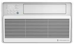
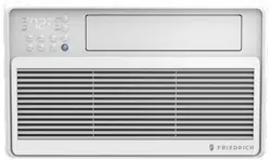
Fixed chassis, cool only
CCF05A10A, CCF06A10A, CCF08A10A, CCF10A10A
CCF12A10A
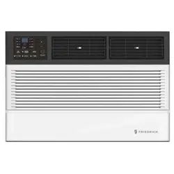
Slide out chassis, cool only
CCW06B10A, CCW08B10A, CCW10B10A, CCW12B10A
CCW15B10A, CCW18B30A, CCW24B30A
Slide out chassis, heat & cool
CEW08B11A, CEW12B33A, CEW18B33A, CEW24B33A
Chill Premiere Series Models
Unifit Series Models
Cool Only
UCT08A10A, UCT10A10A, UCT10A30A, UCT12A10A,
UCT12A30A, UCT14A30A
Cool with Electric Heat
UET08A11A, UET10A33A, UET12A33A, UET14A33A

2 PB
Table of Contents
INTRODUCTION 3
IMPORTANT SAFETY INFORMATION 3
PERSONAL INJURY OR DEATH HAZARDS 4
SPECIFICATIONS 7
Electrical Data 9
Product Dimensions 11
OPERATION 12
Remote Control 12
Control Panel 13
Sequence of Operation 15
R-410A SEALED SYSTEM REPAIR 22
Refrigerant Charging 23
Undercharged Refrigerant Systems 24
Overcharged Refrigerant Systems 25
Restricted Refrigerant System 26
Sealed System Method of Charging/ Repairs 27
COMPONENT TESTING 28
Hermetic Components Check 28
Reversing valve description and operation 29
Testing The Reversing Valve Solenoid Coil 30
Checking The Reversing Valve 31
Replace The Reversing Valve 32
Touch Test Chart : To Service Reversing Valves 33
Compressor Checks 34
Compressor Replacement 36
Compressor Replacement -Special Procedure in Case of Compressor Burnout 37
Fan Motor 38
Capacitors 38
TROUBLESHOOTING 39
Product Does Not Operate At All 40
Indoor Fan Does Not Operate At All 41
Compressor Or Outdoor Fan Does Not Operat At All 42
Display E1 or E2 43
WIRING DIAGRAMS 44
Chill Premier CCF 44
Chill Premier CCW 46
Chill Premier CEW 48
Unit 51
PARTS CATALOG 53
Chill Premier Models: CCW06B10A CCW08B10A CCW10B10A CCW12B10A 53
Chill Premier Models: CCW06B10A CCW08B10A CCW10B10A CCW12B10A 54
Chill Premier Models: CCW15B10A CCW18B30A 56
Chill Premier Models: CCW24B30A 59
Chill Premier Models: CCW24B30A 60
Chill Premier Models: CEW08B11A, CEW12B33A 63
Chill Premier Models: CEW08B11A, CEW12B33A 64
Chill Premier Models: CEW08B11A, CEW12B33A 65
Chill Premier Models: CEW18B33A 66
Chill Premier Models: CEW24B33A 70
Chill Premier Models: CCF05A10A CCF06A10A CCF08A10A 75
Chill Premier Models: CCF10A10A CCF12A10A 78
Unit Models: UCT08A10A UCT10A10A UCT12A10A UCT10A30A 81
Unit Models: UCT12A30, UCT14A30A 84
Unit Models: UET08A11A UET10A33A UET12A33A 86
Unit Models: UET14A33A 89
Available Accessories 91
FRIEDRICH AUTHORIZED PARTS DEPOTS 94
3 PB
Your safety and the safety of others is very
important.
We have provided many important safety messages in this manual and on your appliance. Always
read and obey all safety messages.
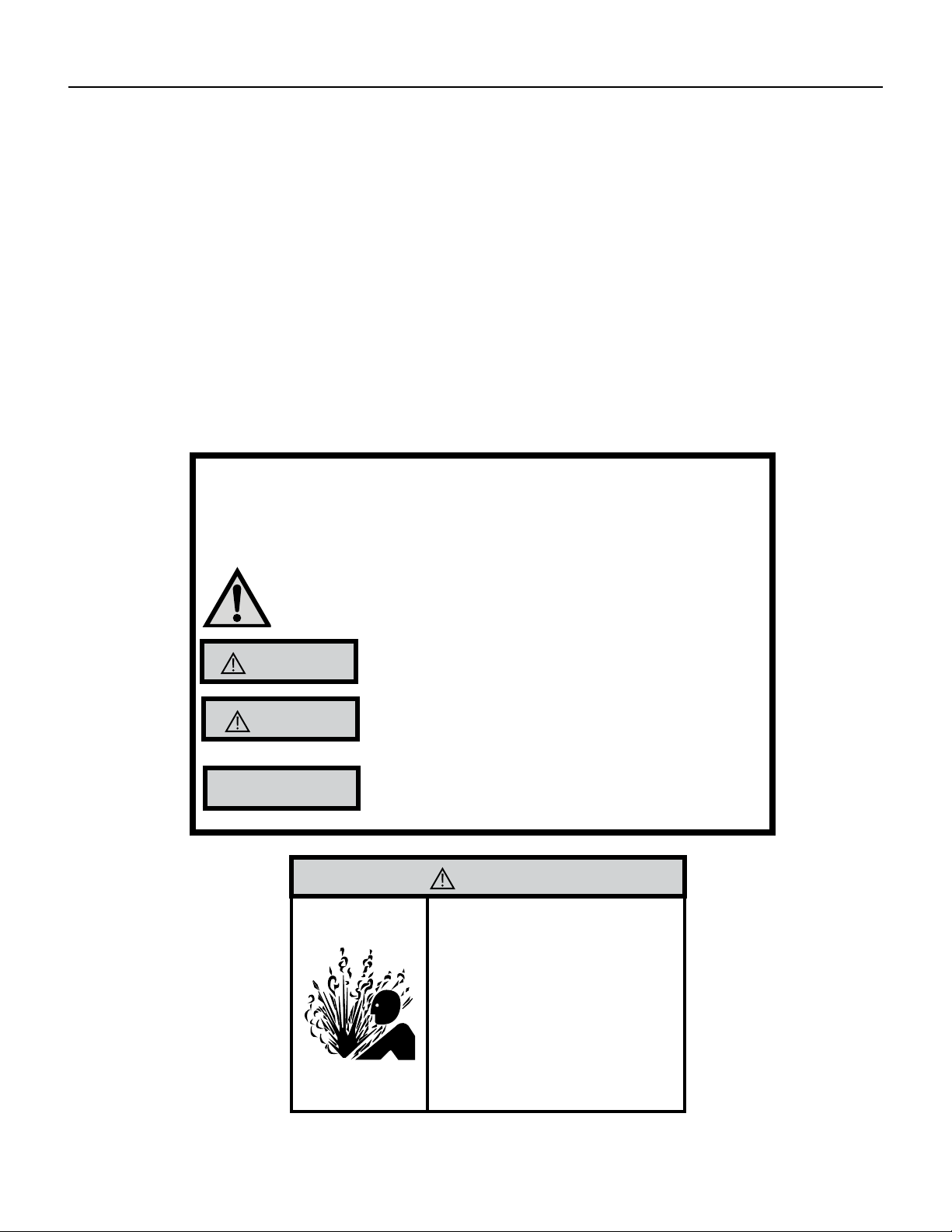
This is a safety Alert symbol.
This symbol alerts you to potential hazards that can kill or hurt you and others.
All safety messages will follow the safety alert symbol with the word
“WARNING”
or “CAUTION”. These words mean:
Indicates a hazard which, if not avoided, can result in severe personal
injury or death and damage to product or other property.
Indicates a hazard which, if not avoided, can result in personal injury
and damage to product or other property.
All safety messages will tell you what the potential hazard is, tell
you how to reduce the chance of injury, and tell you what will happen
if the instructions are not followed.
Indicates property damage can occur if instructions are not followed.
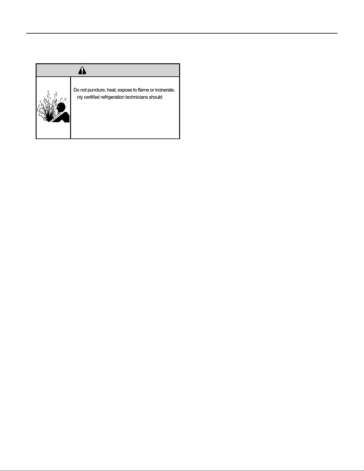
WARNING
Refrigeration system
under high pressure
Do not puncture, heat, expose to ame or
incinerate.
Only certied refrigeration technicians
should service this equipment.
R410A systems operate at higher pressures
than R22 equipment. Appropriate safe
service and handling practices must be used.
Only use gauge sets designed for use with
R410A.
Do not use standard R22 gauge sets.
NOTICE
CAUTION
WARNING
The information in this manual is intended for use by a qualied technician who is familiar with the safety procedures
required for installation and repair, and who is equipped with the proper tools and test instruments required to
service this product.
Installation or repairs made by unqualied persons can result in subjecting the unqualied person making such
repairs as well as the persons being served by the equipment to hazards resulting in injury or electrical shock
which can be serious or even fatal.
Safety warnings have been placed throughout this manual to alert you to potential hazards that may be encountered.
If you install or perform service on equipment, it is your responsibility to read and obey these warnings to guard
against any bodily injury or property damage which may result to you or others.
IMPORTANT SAFETY INFORMATION
INTRODUCTION
4 PB
SAFETY
FIRST
WARNING AVERTISSEMENT ADVERTENCIA
Do not remove, disable
or bypass this unit’s
safety devices. Doing so
may cause re, injuries,
or death.
Ne pas supprime, désactiver
ou contourner cette l´unité
des dispositifs de sécurité,
faire vous risqueriez de
provoquer le feu, les
blessures ou la mort.
No eliminar, desactivar o
pasar por alto los
dispositivos de seguridad de
la unidad. Si lo hace podría
producirse fuego, lesiones
o muerte.
ELECTRICAL HAZARDS:
• Unplug and/or disconnect all electrical power to the unit before performing inspections, maintenance, or service.
• Make sure to follow proper lockout/tag out procedures.
• Always work in the company of a qualied assistant if possible.
• Capacitors, even when disconnected from the electrical power source, retain an electrical charge potential
capable of causing electric shock or electrocution.
• Handle, discharge, and test capacitors according to safe, established, standards, and approved procedures.
• Extreme care, proper judgment, and safety procedures must be exercised if it becomes necessary to test or
troubleshoot equipment with the power on to the unit.
• Do not spray water on the air conditioning unit while the power is on.
• Electrical component malfunction caused by water could result in electric shock or other electrically unsafe
conditions when the power is restored and the unit is turned on, even after the exterior is dry.
• Use air conditioner on a single dedicated circuit within the specied amperage rating.
• Use on a properly grounded outlet only.
• Do not cut or modify the power supply cord or remove the ground prong of the plug.
• Never operate the unit on an extension cord.
• Follow all safety precautions and use proper and adequate protective safety aids such as: gloves, goggles,
clothing, properly insulated tools, and testing equipment etc.
• Failure to follow proper safety procedures and/or these warnings can result in serious injury or death.
INTRODUCTION
PERSONAL INJURY OR DEATH HAZARDS

5 PB
• REFRIGERATION SYSTEM REPAIR HAZARDS:
• Use approved standard refrigerant recovering procedures and equipment to relieve high pressure before
opening system for repair.
• Do not allow liquid refrigerant to contact skin. Direct contact with liquid refrigerant can result in minor to
moderate injury.
• Be extremely careful when using an oxy-acetylene torch. Direct contact with the torch’s ame or hot surfaces
can cause serious burns.
• Make certain to protect personal and surrounding property with re proof materials and have a re extinguisher
at hand while using a torch.
• Provide adequate ventilation to vent off toxic fumes, and work with a qualied assistant whenever possible.
• Always use a pressure regulator when using dry nitrogen to test the sealed refrigeration system for leaks,
ushing etc.
• MECHANICAL HAZARDS:
• Extreme care, proper judgment and all safety procedures must be followed when testing, troubleshooting,
handling, or working around unit with moving and/or rotating parts.
• Be careful when, handling and working around exposed edges and corners of the sleeve, chassis, and other unit
components especially the sharp ns of the indoor and outdoor coils.
• Use proper and adequate protective aids such as: gloves, clothing, safety glasses etc.
• Failure to follow proper safety procedures and/or these warnings can result in serious injury or death.
• PROPERTY DAMAGE HAZARDS
• FIRE DAMAGE HAZARDS:
• Read the Installation/Operation Manual for the air conditioning unit prior to operating.
• Use air conditioner on a single dedicated circuit within the specied amperage rating.
• Connect to a properly grounded outlet only.
• Do not remove ground prong of plug.
• Do not cut or modify the power supply cord.
• Do not use extension cords with the unit.
• Be extremely careful when using acetylene torch and protect surrounding property.
• Failure to follow these instructions can result in re and minor to serious property damage.
• WATER DAMAGE HAZARDS:
• Improper installation, maintenance or servicing of the air conditioner unit can result in water damage to personal
items or property.
• Insure that the unit has a sufcient pitch to the outside to allow water to drain from the unit.
• Do not drill holes in the bottom of the drain pan or the underside of the unit.
• Failure to follow these instructions can result in damage to the unit and/or minor to serious property damage.
INTRODUCTION
PERSONAL INJURY OR DEATH HAZARDS

6 PB
INTRODUCTION
This service manual is designed to be used in conjunction with the installation and operation manuals provided
with each air conditioning system.
This service manual was written to assist the professional service technician to quickly and accurately diagnose
and repair malfunctions.
Installation procedures are not given in this manual. They are given in the Installation/Operation manual which
can be aquired on the Friedrich website.
IMPORTANT: It will be necessary for you to accurately identify the unit you are servicing, so you can be certain of
a proper diagnosis and repair.
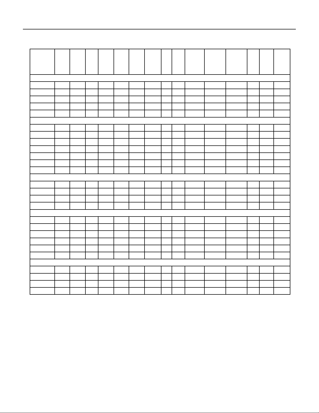
7 PB
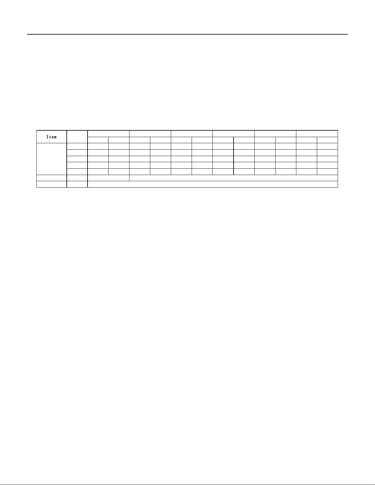
SPECIFICATIONS
Figure 201 (Refrigeration Systems Performance Data)
Model Cooling
Btu
Heating
Btu
Volts
Rated
Cooling
Amps
Cooling
Watts
Heating
Amps
Heating
Watts
EER CEER Moisture
Removal-
Pints/HR
Refrigerant Refrigerant
Charge
CFM Sleeve Weight
Net./
Ship
lbs.
FIXED CHASSIS, COOL ONLY (WINDOW INSTALLATION ONLY)
CCF05A10A 5200 — 115 4.3 459 — — 12.1 12.1 1.0 R410A 12.35 141 44/51
CCF06A10A 6000 — 115 4.3 492 — — 12.1 12.1 0.9 R410A 13.76 141 44/51
CCF08A10A 8000 — 115 5.8 661 — — 12.1 12.0 1.0 R410A 14.46 206 51/57
CCF10A10A 10000 — 115 7.3 826 — — 12.1 12.0 1.2 R410A 19.4 282 64/73
CCF12A10A 12000 — 115 8.6 992 — — 12.1 12.0 1.5 R410A 22.93 270 73/82
CHILL PREMIER SLIDE OUT CHASSIS, COOL ONLY
CCW06B10A 6000 — 115 4.3 492 — — 12.2 12.1 0.9 R410A 13.76 200 44/51
CCW08B10A 8000 — 115 5.8 661 — — 12.1 12.0 1.0 R410A 14.46 250 44/61
CCW10B10A 10000 — 115 7.3 826 — — 12.1 12.0 1.2 R410A 19.4 300 51/68
CCW12B10A 12000 — 115 8.6 992 — — 12.1 12.0 1.5 R410A 22.93 330 64/86
CCW15B10A 15000 — 115 11.0 1270 — — 11.9 11.8 2.0 R410A 28.22 400 73/93
CCW18B30A 18000 — 230 7.1 1525 — — 11.9 11.8 2.7 R410A 29.98 520 106/136
CCW24B30A 24000 — 230 10.2 2308 — — 10.4 10.3 2.7 R410A 37.03 590 117/144
CHILL PREMIER SLIDE OUT CHASSIS, HEAT & COOL
CEW08B11A 8000 4200 115 6.3 670 — — 11.0 10.9 2.1 R410A 14.46 250 44/61
CEW12B33A 12000 10600 230 4.8 1060 — — 11.0 10.9 3.3 R410A 29.98 265 64/86
CEW18B33A 18000 10600 230 7.2 1600 — — 10.8 10.7 5.5 R410A 29.98 430 106/136
CEW24B33A 24000 10600 230 10.6 2340 — — 9.5 9.4 6.5 R410A 37.03 560 117/144
UNI-FIT® Cool Only
UCT08A10A 8000 — 115 6.9 755 — — 10.7 10.6 0.8 R410A 14.46 265 64 64/78
UCT10A10A 10000 — 115 8.3 940 — — 10.7 10.6 1.25 R410A 19.05 247 74 74/86
UCT10A30A 10000 — 230 4.5 940 — — 10.7 10.6 1.25 R410A 19.75 265 74 74/86
UCT12A10A 12000 — 115 10.1 1130 — — 10.6 10.5 1.7 R410A 22.22 276 75 75/88
UCT12A30A 12000 — 230 5.4 1130 — — 10.6 10.5 1.7 R410A 22.22 265 75 75/88
UCT14A30A 14000 — 230 7.2 1490 — — 9.4 9.3 2.15 R410A 22.22 265 76 76/89
UNI-FIT® Cool with Electric Heat
UET08A11A 8000 4200 115 7.2 810 12.5 1320 9.7 9.6 0.75 R410A 13.76 265 66 66/79
UET10A33A 10000 10600 230 4.9 1030 15 3500 9.7 9.6 1.2 R410A 17.99 276 75 75/87
UET12A33A 12000 10600 230 5.9 1230 15 3500 9.7 9.6 1.65 R410A 20.1 276 76 76/89
UET14A33A 14000 10600 230 7.2 1490 15 3500 9.4 9.3 2.15 R410A 22.22 265 77 77/90
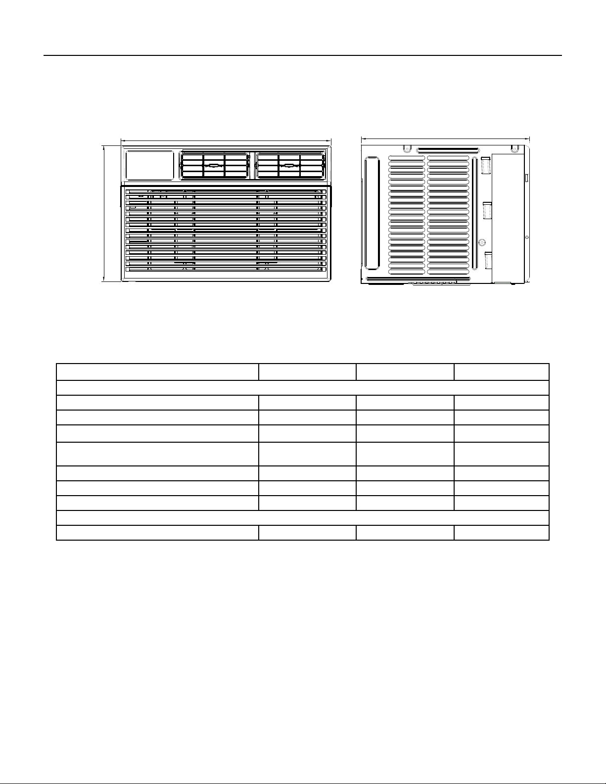
8 PB
SPECIFICATIONS
Installation Clearances
Improper installation of the Air Condtioner can cause poor performance and premature wear of the unit.
Ensure that the unit is installed with proper clearances as described below.
Ensure no obstructions. or enclosures are within clearances limits to allow for proper airow.
Clearances
Rear of Unit - Three (3) feet
Figure 203 Unit ( Sleeve Dimensions)
Model
Height
Inches
Width
Inches
Depth
Inches
Minimum
Extension
Into Room
Inches
Minimum
Extension
Outside
Inches
Window
Width
Inches
Minimum* Maximum
CCF05A10A, CCF06A10A,
13
5
/
8
18
5
/
8
15
5
/
8
— —
26 36
CCF08A10A 13
3
/
8
18
5
/
8
17
5
/
8
— —
26 36
CCF10A10A, CCF12A10A 15
1
/
8
19
7
/
8
21
3
/
4
— —
26 36
CCW06B10A, CCW08B10A,
CEW08B11A, CCW10B10A,
CCW12B10A, CEW12B33A,
14
5
/
8
19
3
/
4
23
3
/
4
— —
26 36
CCW15B10A, CCW18B30A,
CEW18B33A
18
23
7
/
8
25
3
/
8
— —
26 36
CCW06B10B, CCW08B10B 13
3
/
8
18
5
/
8
17
5
/
8
— —
26 36
CCW24B30A, CEW24B33A
18
5
/
8
27 26
5
/
8
— —
26 36
Figure 202 (Chill Premier Installation)
Sleeve
Dimen-
sions
Friedrich
USC Sleeve
Amana
Carrier
(51S
Series)
Fedders/
Emerson/
Friedrich
WSE
Emer-
son/
Fedders
GE/
Hotpoint
Whirl-
pool
White-Westing-
house/
Frigidaire/
Carrier (52F
Series)
Height 15
1
/
2
” 15
5
/
8
” 16
7
/
8
” 16
3
/
4
” 15
3
/
4
” 15
5
/
8
” 16
1
/
2
” 15
1
/
4
”
Width
25
7
/
8
” 26” 25
3
/
4
” 27” 26
3
/
4
” 26” 25
7
/
8
” 25
1
/
2
”
Depth
16
3
/
4
” 16
7
/
8
” 18
5
/
8
” 16
3
/
4
” or
19
3
/
4
”
15” 16
7
/
8
” 17
1
/
8
” or
23”
16”, 17
1
/
2
” or
22”
9 PB
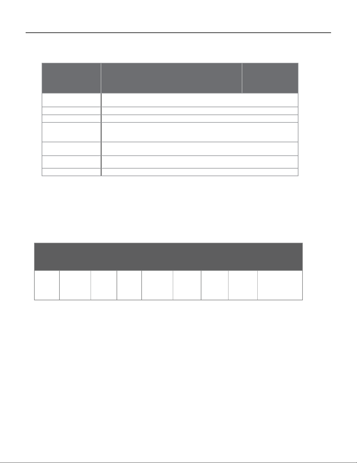
SPECIFICATIONS
Electrical Data
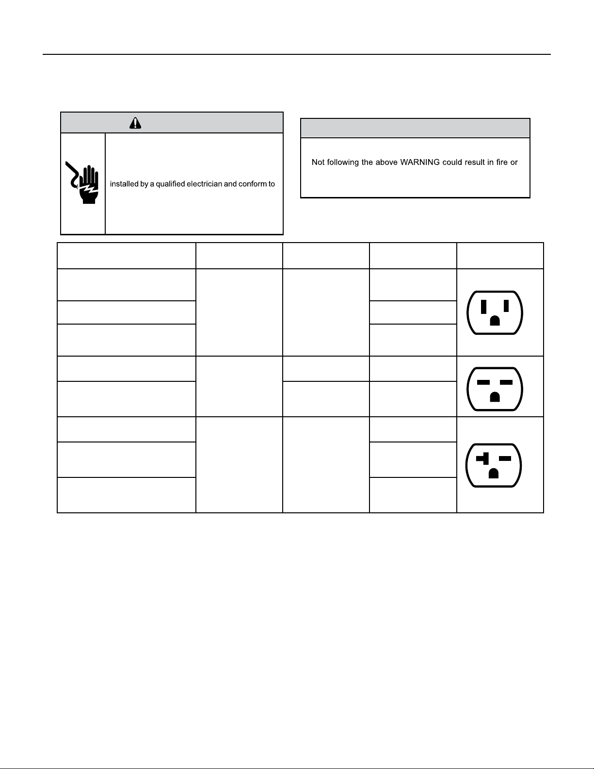
WARNING
ELECTRIC SHOCK HAZARD
Turn off electric power before service or
installation.
All electrical connections and wiring MUST be
the National Electrical Code and all local codes
which have jurisdiction.
Failure to do so can result in personal injury or
death.
NOTICE
FIRE HAZARD
electically unsafe conditions which could cause moderate
or serious property damage.
Read, understand and follow the above warning.
Figure 204 (Circuit Breaker / Plug / Receptacle / Cord Rating)
Model Circuit Rating
Breaker or T-D Fuse
Plug Face
(NEMA#)
Power Cord
Length (ft.)
Wall Outlet
Appearance
ALL CCF MODELS. CCW06B10A,
CCW08B10A, CCW10B10A,
CCW12B10A, CEW08B11A
125V-15A 5-15P
6
Chill® Premier
CCW15B10A
5.5
UNI-FIT®
UCT08A10A, UCT10A10A,
UCT12A10A
6
Chill® Premier
CCW18B30A, CCW24B30A
250V - 15A
6 - 15P 4.5
UNI-FIT®
UET10A33A, UET12A33A,
UET14A33A
6-20P 6
Chill® Premier
CCW18B30A, CCW24B30A
250V-20A 6-20P
4
Chill® Premier
CEW12B33A, CEW18B33A,
CEW24B33A
6
UNI-FIT®
UET10A33A, UET12A33A,
UET14A33A
4.75
10 PB
WARNING
Electrical Shock Hazard
Make sure your electrical receptacle
has the same conguration as your air
conditioner’s plug. If different, consult
a Licensed Electrician.
Do not use plug adapters.
Do not use an extension cord.
Do not remove ground prong.Always
plug into a grounded 3 prong outlet.
Failure to follow these instructions
can result in death, re, or electrical
shock.
Wire Size - Use ONLY wiring size recommended for single outlet branch circuit.
Fuse/ Circuit Breaker - Use ONLY the correct HACR type and size fuse/circuit breaker. Read electrical ratings on
unit’s rating plate. Proper circuit protection is the responsibiity of the homeowner.
Grounding - Unit MUST be grounded from branch circuit through service cord to unit, or through separate ground
wire provided on permanently connected units. Be sure that branch circuit or general purpose outlet is grounded.
Receptacle - The eld supplied outlet must match plug on service cord and be within reach of service cord. Do
NOT alter the service cord or plug. Do NOT use an extension cord. Refer to the table above for proper receptacle
and fuse type.
Make sure the wiring is adequate for your unit.
If you have fuses, they should be of the time delay type. Before you install or relocate this unit, be sure that the
amperage rating of the circuit breaker or time delay fuse does not exceed the amp rating listed in Table 206.
DO NOT use an extension cord.
The cord provided will carry the proper amount of electrical power to the unit; an extension cord may not.
Make sure that the receptacle is compatible with the air conditioner cord plug provided.
Proper grounding must be maintained at all times. Two prong receptacles must be
replaced with a grounded receptacle by a certied electrician.
The grounded receptacle should meet all national and local codes and ordinances. You must use the three prong plug
furnished with the air conditioner. Under no circumstances should you remove the ground prong from the plug.
SPECIFICATIONS
Electrical Data
11 PB
SPECIFICATIONS
Product Dimensions
A
B
C
Model A “(inches) B “(inches) C “(inches)
Chill® Premier
CCF05A10A, CCF06A10A 13 3/8 18 5/8 15 5/8
CCF08A10A 13 3/8 18 5/8 17 5/8
CCF10A10A, CCF12A10A 15 1/8 19 7/8 21 3/4
CCW06B10A, CCW08B10A, CEW08B11A,
CCW10B10A, CCW12B10A, CEW12B33A,
14 5/8 19 3/4 23 3/4
CCW06B10B, CCW08B10B 13 3/8 18 5/8 17 5/8
CCW15B10A, CCW18B30A, CEW18B33A 18 23 7/8 25 3/8
CCW24B30A, CEW24B33A 18 5/8 27 26 5/8
UNI-FIT®
All Models 24 7/32 14 17/32 20 9/32
Figure 205
12 PB
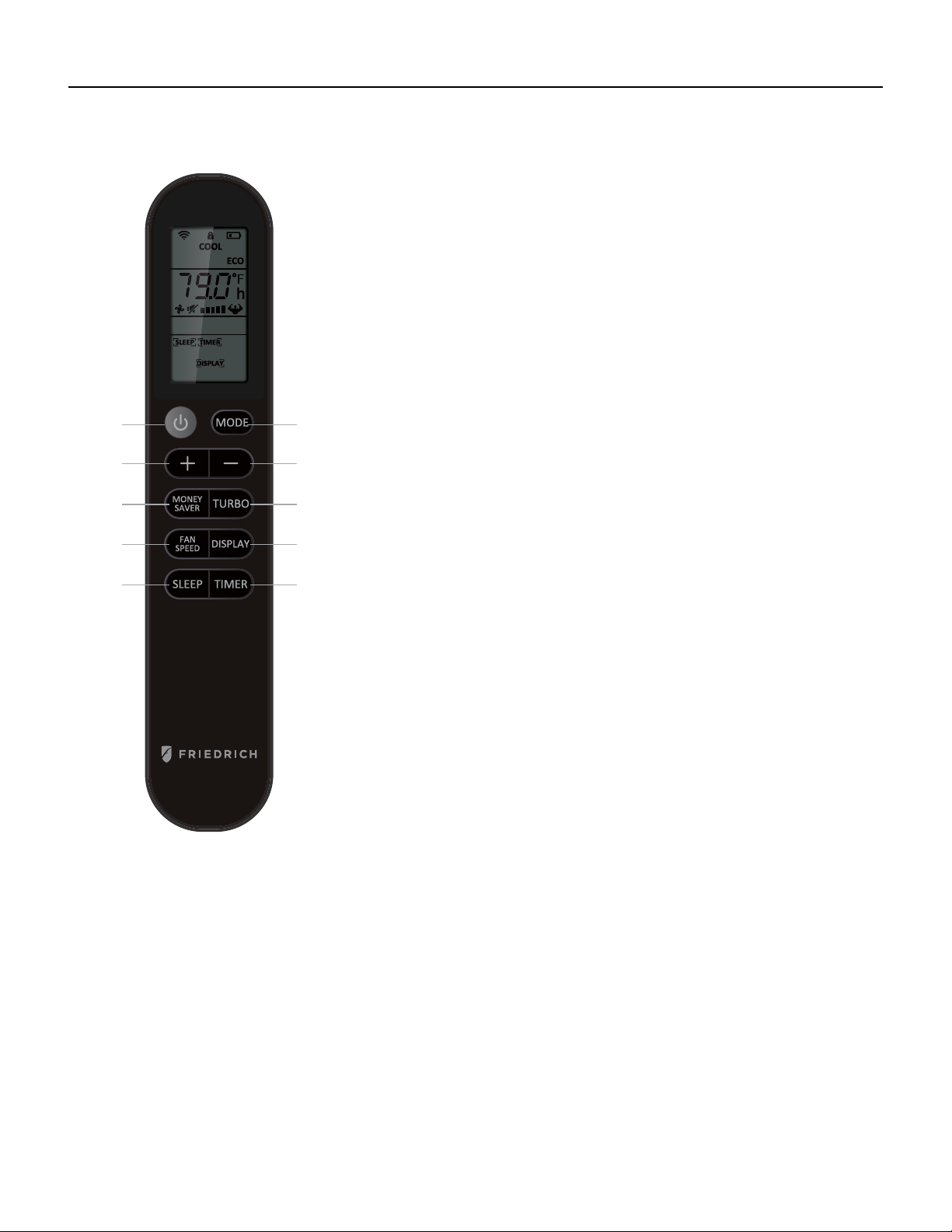
OPERATION
Remote Control
Figure 301 (Remote Control Operation)
1
2
33
4
5
67
8
9
1. Power: Turn the air conditioner on and off. This button will clear the TIMER
setting.
2. MODE: Press the button to select the mode of operation, AUTO, COOL, DRY, FAN ONLY,
HEAT.
Note: The HEAT mode is only for some heating models. If you do not need it, press the
MODE button for more than 5 seconds to delete the HEAT function, and the COOL mode
will be selected automatically. Press the MODE again for more than 5 seconds to add the
HEAT function, and the HEAT mode will be selected automatically.
3. + And - : Use these buttons to increase or decrease the setting Temperature or
Timer. Setting temperature range: 61 ~88°F or 16 ~31°C .
Note: After setting temperature with remote using th + and - buttons, both the
remote display and the unit display will automatically turn off after a short time.
This does not affect the unit operation.
4. TURBO: When the remote is ON, press the button to activate the TURBO
function, under AUTO/COOL/FAN ONLY mode. Press again to cancel the TURBO
function, and the fan speed will change to pre-setting before.
Note: °F and °Cchange: After inserting the batteries, in the off state within 3
minutes, press the TURBO button for more than 5 seconds to switch the Fahrenheit
(°F) or Celsius (°C) degree display.
5. DISPLAY: When the unit is ON, press the button, to switch off/on all lights or
LED display. And this function will be canceled when changing mode.
6. TIMER: Use the button to set the TIMER, or cancel the TIMER.
TIMER OFF: When the unit is ON, the timed OFF is programmed by pressing TIMER
button, the remote will display 6 hours pre-setting at rst.
Set the rest time by pressing the button or until the needed rest time display, then
press TIMER button again to conrm.
TIMER ON: When the unit is OFF, the timed ON is programmed by pressing TIMER
button, the remote will display 6 hours pre-setting at rst. Set the rest time by
pressing the button or until the needed rest time display, then press TIMER button
again to conrm. Later, the remote screen will keep display [TIMER] icon.
Note: When TIMER ON, it cannot select Sleep mode, but can pre-set Mode,
temperature, fan speed, ECO.
7. SLEEP: Press the SLEEP button, all of the display lights will turn off after a
while, but the Sleep light is always on. In SLEEP mode, the air conditioner will
automatically adjust the temperature and fan speed to make the room more
comfortable during the night. The set temperature will automatically raise every
30-60 minutes and at most change six times until the set temperature is 81 or
82°F. This function can be selected when COOL or HEAT mode.
8. FAN SPEED: Press the FAN SPEED button to choose the fan speed options. You can choose Hi, Med, Lo or Auto speed in
COOL or HEAT mode and choose Hi, Med, Lo in FAN mode. When DRY mode, it is only Low fan speed.
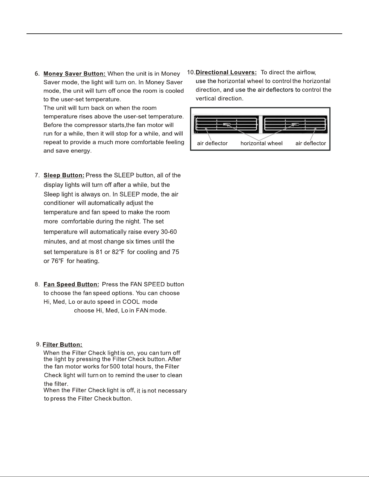
9. MONEY SAVER: When the unit is in COOL mode, press the button to MONEY SAVER function. In MONEY SAVER mode, the
unit will turn off once the room is cooled to the user set temperature. The unit will turn back on when the room temperature
rises above the user set temperature. Before the compressor starts, the fan motor will run for 20 sec., then it will stop for 10
min., and will repeat to provide a much more comfortable feeling and save energy.
Battery size: AAA
Note: Do not mix old and new batteries or different types of AAA batteries.
13 PB
OPERATION
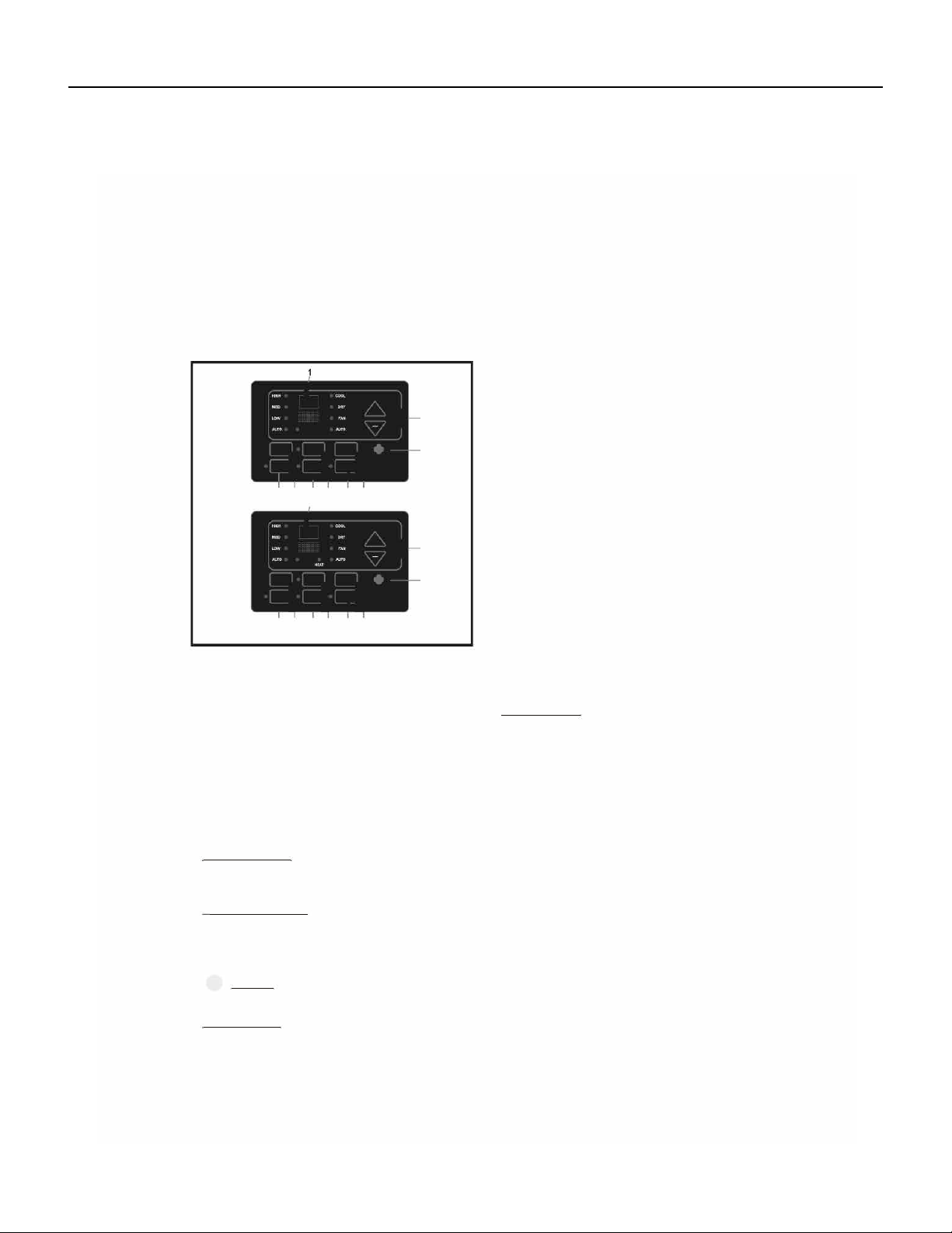
Control Panel
USING YOUR AIR CONDITIONER
Electronic Control Panel & Remote Control
For Cooling model
I
'"
MON
0
l
For Heating model
1
I
'"
MON
+
0
l
>
>
Air Conditioner Controls
Normal Operating Sounds
2
2
3
@
14 PB
OPERATION
Control Panel
mode and
or HEAT
15 PB
OPERATION
Sequence of Operation
Main function
NOTES:
RT------Room Temperature.
IPT------Indoor Pipe (Coil) Temperature.
ST------indoor Set Temperature.
OPT---Outdoor Pipe (Coil) Temperature.
CRT---Compensated Room Temperature
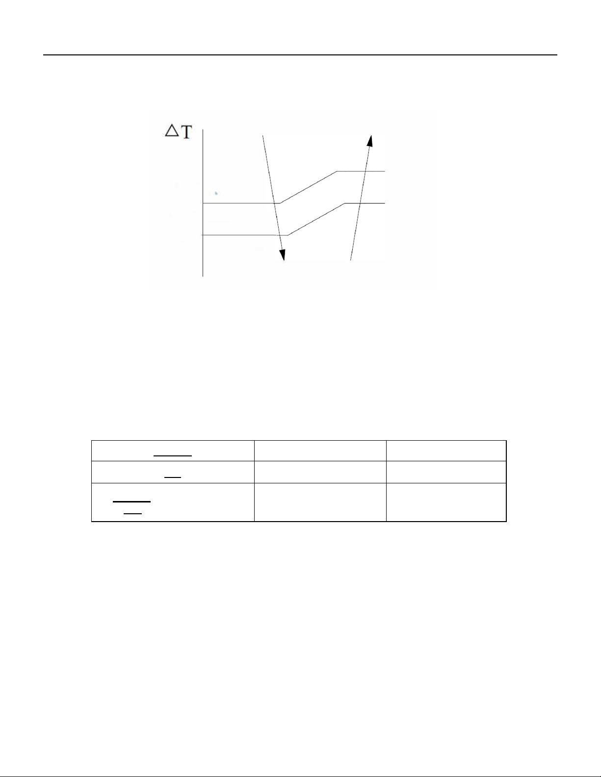
1. Cooling mode
In the cooling mode, COOL indicator is ON, the set temperature and fan speed could be changed or adjusted.
a. When RT-ST≥ 33.8°F the compressor operates if there is not any protection or failure happened.
b. When RT-ST< 30.2°F the compressor stops, and fan motor keeps operation continuous.
c. When 30.2°F ≤RT-ST<33.8°F the compressor keeps former status.
1.1 Indoor fan motor control
1.1.1 Indoor fan motor could be controlled by Auto, Low, Med and High speed circularly .
1.1.2 Indoor fan motor Auto control as below:
a) In cooling mode T=RT-ST
b) While T<32°F, operates in low speed;
c) If T= 35.6°F, in medium speed
d )If T≥39.2°F , in high speed
e) If 35.6°F < T < 39.2°F , The fan motor runs at original speed while it was set in High or Med mode. If
original at Low speed, it will change to Med speed automatically.
f) If 32°F ≤ T < 35.6°F, , The fan motor operates at original speed while it was set in Low or Med mode. If
original at High speed, it will change to Med automatically.
g) When fan speed changes due to the temperature variation, it could be changed only by sequence as
High, Med to Low speed or Low, Med to High speed, and each status will keep at least 2 minutes.
35.6°
F
39.2°F
16 PB
OPERATION
Sequence of Operation
35.6°
F
39.2°F
Auto fan speed in cooling mode
2. Dry mode
While selected to Dry mode, AC works at set temperature to 44.6°F for 3 minutes. After that the set temperature change to be
RT 28.4°F, the compressor works as cooling mode, and indoor fan motor operates at low speed.
The fan speed can not be changed while in dry mode, but the air direction can be adjusted.
3. I FEEL Mode
3.1 The operation mode and initial ST are generated by the Initial RT, and the operation mode is enabled once unless
AC is switched off and powered on again. While I FEEL is changed from other mode , the AC will operate based on the RT
temperature judgement.
3.2 PCB with Auto Restart Function, while power on again,
a). With Auto Restart Function activated, AC runs according to the temperature judgement.
b). If without Auto Restart Function or the function is shut off, AC works on stand by.
Operation MODE Initial RT Initial ST
Cooling
RT ≥78.8ºF 73.4ºF
Dry
> RT ≥
RT-
RT <
Heating for Heat Pump or
Fan for Cooling Only.
78.8ºF
73.4ºF
35.6°F
28.4°F
35.6°F
When AC works in Dry mode after judgement, the display temperature ranges from 3.2°F to 87.8°F, and the set temperature ranges
from 41°F to 87.8°F.
When AC works in Fan mode, the set temperature is xed to 73.4°F, and displays room temperature.
In I FEEL mode (I FEEL cooling or heating), and the PCB receives instructions of temperature adjustment as increasing or decreasing
from remote control, the unit sets ST as the current room temperature±1°F.
( in heating mode, the RT need to be compensated), I FEEL temperature adjusts : ±3.6°F and buzzer responds but controller
takes no action. The set temperature range is from: 60.8°F -87.8°F.
Only works on Cooling or Heating of I FEEL mode, the unit has above temperature control process. In I FEEL Dry or Fan
mode, the buzzer responds, but does not have control of any other operation.
17 PB
OPERATION
Sequence of Operation
4. Heating mode (for Cooling & Heating pump)
When in heating operation mode, the set temperature, fan speed and air direction can be adjusted, compressor does not operate, but
electrical heater works, and indoor fan motor starts up 10s later.
a ST-RT≥ 33.8°F electrical heater operates
b ST-RT < 30.2°F electrical heater stops.
c 30.2°F ≤ST-RT < 33.8° electrical heater keeps the original works status .
Indoor fan motor control
4.1 Indoor fan motor could control by Auto, Low, Med or High speed circularly.
4.2 Indoor fan motor Auto works as follow:
a) In heating mode: T=ST-CRT
b) T 32°F, running in low speed
c) T=35.6°F, in medium speed
d) ≥ 39.2°F,in high speed .
e) 35.6°F < T < 39.2°F , the fan speed keeps in medium or high speed as it’s originally preset, but if the fan was
originally in low speed, it will change to medium.
f) 32°F ≤ T < 35.6°F , the fan speed keeps in low or medium speed as it’s originally preset, if fan in high speed, it
will change to medium speed.
g) When fan speed changes due to the temperature variation , it could be changed only by sequence as High, Med to
Low speed or Low, Med to High speed , and each status keeps at least 2 minutes.
35.6°
F
39.2°F
5. Fan mode
In FAN mode, the corresponding indicator is ON, fan motor runs according to the set speed (default High speed for the rst time),
compressor doesn’t work, Buzzer and PCB do not respond while pressing the UP/DOWN button on remote controller, the fan motor is
adjustable in high, medium or low speed, but no auto wind, 88 digital display shows environment temperature.
6. Sleep mode
6.1 In SLEEP mode, the indoor fan motor runs at low speed, except that the power source and sleep LED is ON, the
running LED and others light are OFF, the condition of timer LED is according to the preset, and all the LEDs will be
OFF after 30 seconds.
6.2 Temperature control
Processing SLEEP while in Cooling or Heating mode, unit runs according to the sleeping operation.
runing time
ST(F) ST(F)
runing time runing time
ST(F)
runing time
ST(F)
runing time
ST(F) ST(F)
runing time
≥82
60 60
no change
60
no change
60
no change
60
no change
60
no change
80
60
82
no change
60 60
no change
60
no change
60
no change
60
no change
78
50
80
60
no change
82
60 60
no change
60
no change
60
no change
77
40
78
50
no change
80
60 60
no change
60
no change
60
no change
75
30
77
no change
40
78
50
80
60 60
no change
60
no change
73
30
75
30
no change
77
40
78
50
80
60 60
no change
71
30
73
no change
30
75
30
77
40
78
50
80
60
no change
≤70
03
4
30
5 8
0
5 75
0
5 9 1
04
10 9
05
80
Fan speedset speed
UP/DOWN swing ON/OFF
initial set
Item
temp.(F)
The controlled
set temperature.
Note:unit---
Time: minute
set speed
keep original
low speed low-low speed
keep angle for cold air prevention
The 1st change The 2nd change The 3rd change The 4th change The 5th change The 6th change
18 PB
OPERATION
Sequence of Operation
a) The indoor fan runs at the set speed when processing sleep mode, after the 1st change, unit runs at low
speed, and after the 2nd change, unit runs at low-low speed ( if AC without low-low speed, it runs at low
speed instead). 10 hours later AC quits from sleep mode and runs at former set fan speed .
b) In SLEEP mode, the vane works according to the preset, after the rst change, vane blade works at cold
air prevention angle. 10 hours later AC quits from sleep and works as the former preset.
c) The set fan speed refers to the preset value before processing SLEEP mode. If the unit just on stand by
before sleep operation, the set value to be according to low speed . If AC preset in super speed, the set
value will change to high speed, while in Auto wind, it will change to low speed.
B. Sleep mode on Heating operation:
table 2
runing time
ST(F)
runing time
ST(F)
runing time
ST(F)
runing time
ST(F)
runing time
ST(F)
runing time
ST(F)
≥82
60 12 9 06 78 06 9 3 60 60
no change
60
no change
80
60
no change
78
60
77
60
75
60 60
no change
60
no change
78
60
no change
77
60
75
60 60
no change
60
no change
60
no change
77
60
75
no change
60 60
no change
60
no change
60
no change
60
no change
≤75
no change
60 60
no change
60
no change
60
no change
60
no change
60
no change
Fan speed
no change
set speed
ON/OFFUP/DOWN swing keep original
The 5th change The 6th change
only High speed change to Med speed, otherwise keep the set fan speed
The controlled
set temperature.
Note:unit---
Item
Time: minute
set speed
initial set
temp.(F)
The 1st change The 2nd change The 3rd change
The 4th change
1) The indoor fan runs at the set speed when processing in sleep mode, after the rst change, unit changes to
medium speed if the preset is in high operation, and the medium and low speed preset will keep the original even
after the rst change. 10 hours later AC quits from sleep mode and runs at former set fan speed
2) Processing SLEEP mode, the vane works according to the preset, 10 hours later AC quits from sleep and works as
the former preset.
3) The set fan speed refers to the preset value before processing SLEEP mode. If the unit just on stand by before
sleep operation, the set value to be according to low speed. if AC preset in super speed, the set value will change to
high speed, while in Auto wind, it change to low speed.
Sleep process control
1) If the set temperature is changed during the period of sleep mode, it is also executed as the initial sleep set, and
the change time is reset to 0, the temperature change will be restarted, but the 10 hours running time will not be
reset as 0, it will accumulate continuously.
2) The fan speed can not be changed during sleep mode.
3) During the sleep period in cooling mode, the new set will be executed if the vane work status is changed, the anti-
cold angle will not be executed.
4) During the sleep period in heating mode, the wind speed and vane swinging for cold air prevention function is
selected rst.
The sleep instruction in Cooling or Heating of I FEEL mode
1) The current set temperature is set as initial value if sleep mode has not been set before processing sleep mode.
2) If the set temperature is changed, the change times is reset to 0, the new set temperature will be executed, 10
hours timing will be continued.
3) There is other operation during sleep mode, e.g. vane operation, AC keeps operation continuously with the initial
value no exchanged.
4) The sleep mode category is changed during sleep operation, the initial set temperature in cooling or heating of I
FEEL mode will be set as initial running value if no temperature adjustment; or the temperature after increased or
decreased will be set as initial running value after temperature adjustment; and the change times is reset to 0, 10
hours timing accumulation will be restarted.
5) The unit works according to the new set temperature when operating remote controller or other controller to quit sleep
mode.
7. Auto Restart Function (Optional) .
7.1 PCB with auto restart function will keep the operation parameters in EEPROM even with power off. And the unit
can restore operation as the former status automatically while power is on.
7.2 The status parameters include the set mode, fan speed, set temperature and the vane blade position when unit
is off (the swinging status will be remembered when the vane was set as swinging)
7.3 Pressing sleep button 10 times within 8 seconds during running status, the Auto Restart Function could be
activated or turned off; The buzzer sounds 3 times BIBI when activated and 4 times BIBI when function is turned off
(operate with remote controller).
8. ECO function
8.1 The adjustable temperature: 16°C-31°C or 61°F-88°F.
8.2 The action temperature and running of compressor is the same as cooling mode.
8.3 The fan speed setting and other assistant function same as cooling mode.
runing time
ST(F)
runing time
ST(F)
runing time
ST(F)
runing time
ST(F)
runing time
ST(F)
runing time
ST(F)
≥82
60 12 9 06 78 06 9 3 60 60
no change
60
no change
80
60
no change
78
60
77
60
75
60 60
no change
60
no change
78
60
no change
77
60
75
60 60
no change
60
no change
60
no change
77
60
75
no change
60 60
no change
60
no change
60
no change
60
no change
≤75
no change
60 60
no change
60
no change
60
no change
60
no change
60
no change
Fan speed
no change
set speed
ON/OFFUP/DOWN swing keep original
The 5th change The 6th change
only High speed change to Med speed, otherwise keep the set fan speed
The controlled
set temperature.
Note:unit---
Item
Time: minute
set speed
initial set
temp.(F)
The 1st change The 2nd change The 3rd change
The 4th change
runing time
ST(F)
runing time
ST(F)
runing time
ST(F)
runing time
ST(F)
runing time
ST(F)
runing time
ST(F)
≥82
60 12 9 06 78 06 9 3 60 60
no change
60
no change
80
60
no change
78
60
77
60
75
60 60
no change
60
no change
78
60
no change
77
60
75
60 60
no change
60
no change
60
no change
77
60
75
no change
60 60
no change
60
no change
60
no change
60
no change
≤75
no change
60 60
no change
60
no change
60
no change
60
no change
60
no change
Fan speed
no change
set speed
ON/OFFUP/DOWN swing keep original
The 5th change The 6th change
only High speed change to Med speed, otherwise keep the set fan speed
The controlled
set temperature.
Note:unit---
Item
Time: minute
set speed
initial set
temp.(F)
The 1st change The 2nd change The 3rd change
The 4th change
19 PB
OPERATION
Sequence of Operation
8.4 The indoor fan motor works as below while RT meets the set temperature to stop compressor:
a) The indoor fan motor runs for 1 min according to the set speed continuously, and then stops.
b) The indoor fan keeps the stopping status in the following 10 min if RT meets the requirement of
compressor stopping work.
c) After 10 min, the indoor fan motor runs for 20 seconds and lets the indoor air ow through the
evaporator.
d) The indoor fan works as step b) and c) circularly.
e) During above process, if RT increase or ST decrease, also RT meet the requirement of compressor
need to work, the unit exits above b), c) & d) circulation----indoor fan motor operation immediately at set
speed, and compressor also starts up while three-min protection is met.
f) If the compressor working condition is not met after switching on the unit, the indoor fan runs at
set speed for 1 min, then runs as step b) and c) circularly; If the compressor working condition is met after
switching on the unit, the indoor fan runs at set speed
g) In above circulation, the 3-min protection for compressor always function.
9. Filter cleaning function
1. The LED for air FILTER will light (ON) when the indoor fan motor work has accumulated 500 hours.
2. Pressing the FILTER button means cleaning is nished, the accumulation hours are reset to 0and start timing
again, the FILTER indicator OFF.
3. 500 accumulation hours could be reset to 0 by pressing the lter cleaning button only.
4. There is no effect on the AC operation even when the lter indicator is ON.
Assistance function
1. Display and Key button
Display: default indicates set temperature (ST).
The key buttons include POWER (ON/OFF), FAN, MODE, UP, DOWN, TIMER, SLEEP, ECO, FILTER cleaning and
HEALTH, the buzzer BIBI response for each valid button pressing.
The detailed instructions are below:
POWER ON/OFF button
When switched on, the indicator displays current set value and the running status can be adjusted by pressing buttons; there
is no display when turned off, press FAN, UP, DOWN and MODE button is invalid; In timer mode, the timer indicator ON and
digital LED displays the remained time, no other indicator, FAN and MODE button invalid. Pressing ON/OFF button may cancel
the timer function. (Note: The Auto Restart Function default activated after production in the factory.)
FAN speed button
Pressing the FAN speed button causes switchover as:
Med speed Low speed Auto speed High speed
MODE button
Cooling Only: Cooling -Dry - Fan - Auto.
Cooling & Heating pump : Cooling - Dry - Fan - Heat - Auto.
UP / DOWN button
It is used for temperature preset and timer adjustment.
When pressing the UP or DOWN button, buzzer response, and the digital display the set temperature or the set time.
In the running status, press SLEEP button 6 times within 8 seconds will be ON or OFF the room temperature display, the
buzzer shortly BIBI twice. (by remote controller)
TIMER button
When unit is working (without time set), press TIMER button to set the AC time to shut down, the timer indicator ON.
When unit is OFF, press TIMER button to set the time of AC power on, the timer indicator ON
The timer can be set from 0.5, 1.0, 1.5, 2.0, ……10, 11, 12…… to 24 hours, it could circulate by dual direction: when showing
0.5, pressing DOWN button, the time changes to 24, vice versa, when showing 24, pressing UP button, the time changes to 0.5.
When 88 digital display timer, press UP/DOWN to adjust the timing time, the number ashes and 10s later, the digital
recovery to display the set temperature. In order to regulate timer quickly in timing mode, pressing the UP/DOWN button for
2 seconds to trigger continuous adjustment with the frequency 5Hz.
FILTER button
When lter light is ON, pressing this button, the light will be OFF. It will be meaningless to press this button while the light is
OFF.
HEALTH button
Pressing this button to turn on anion function, if pressing once more time to shut off anion.
2 BUZZER function

20 PB
OPERATION
Sequence of Operation
Power on controller: Buzzer buzzing once for 0.3s.
Power off unit: Buzzer buzzing once.
Pressing button and\or receiving signal: Buzzer BIBI shortly once.
Malfunction: buzzer BIBI shortly 3 times
Protection / Failure code
1 Anti-frozen protection for indoor evaporator:
If IPT≤32°F for continuous 3min, compressor shut off, fan motor keeps former operation; 3min later, if IPT≥50°F, compressor
start up operation and fan motor keeps the former running status.
2 SENSOR error protection
When sensor short circuit or broken, Room Temperature failure shows E1, and Coil Temperature failure shows E2. When E1
or E2 happened, compressor stops and indoor fan motor operates at the set speed.
When AC on STANDBY, there is no malfunction inspection.
The NTC sensor resistance: 5kΩ/ 77°F
3 Compressor protection
If unit is on STANDBY before power off, there is no 3-min protection while switch on, otherwise the unit always has 3-min
protection.
4 SELF-DIAGNOSIS function
Press the ON/OFF button rst, and then switching on unit. AC works and checks as below accordingly:
Buzzer BIBI 2 times, 88 Digital fully lights, Electric heating (for cooling & heating) , Compressor , High fan speed ,Medium
speed ,Low speed , Health , WIFI LED, indicator of Heat/Cool /High speed/Dry / Medium speed / Low speed/Auto fan/ Timing /
Sleep/ Filter cleaning/ ECO/Health, Room temperature , Indoor coil Temperature , EEPROM calibration etc.
After self-diagnosis, unit to STANDBY (Note: unit with auto restart function will operate according to it’s former status)
21 PB
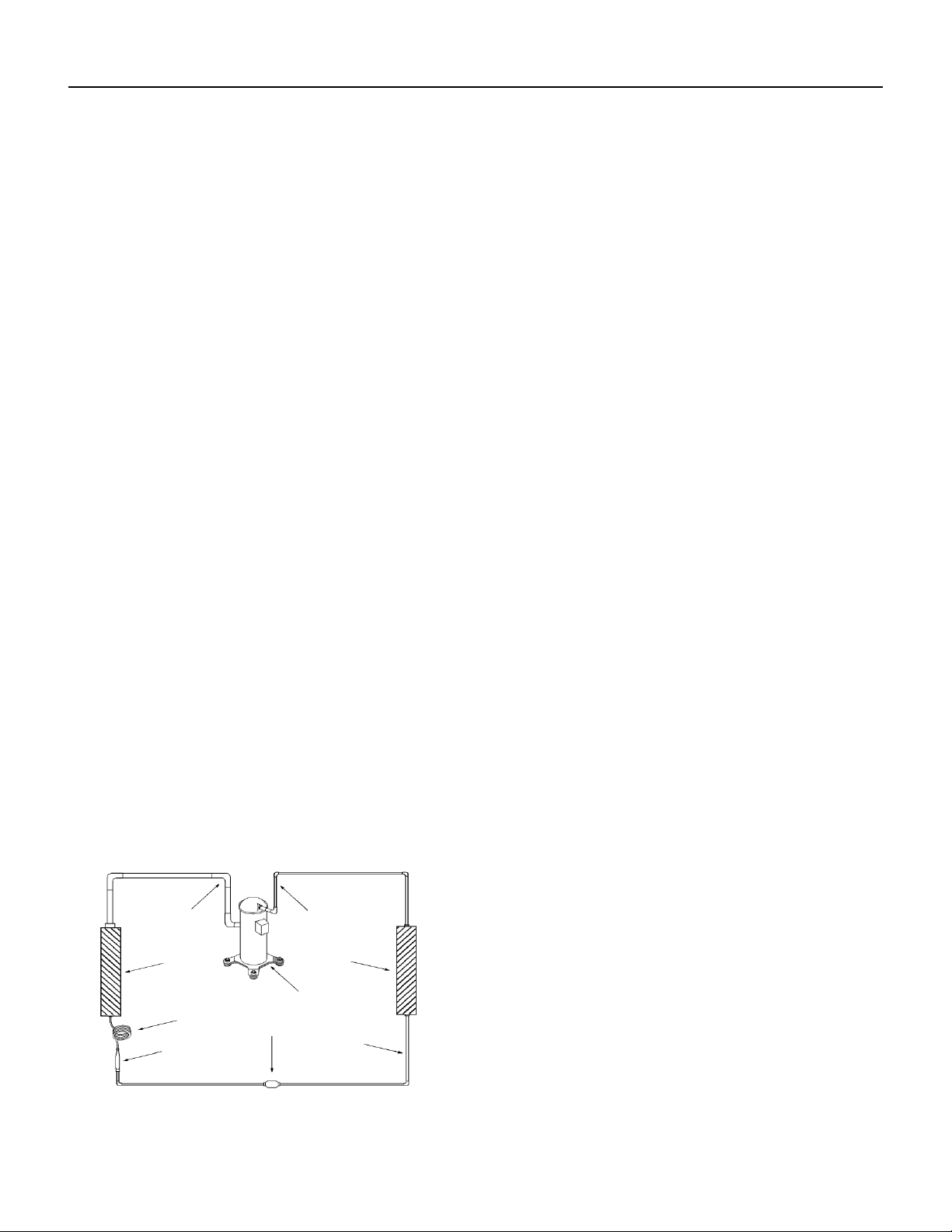
OPERATION
Refrigeration Sequence Of Operation
A good understanding of the basic operation of the refrigeration system is essential for the service technician. Without this
understanding, accurate troubleshooting of refrigeration system problems will be more difcult and time consuming, if not (in
some cases) entirely impossible. The refrigeration system uses four basic principles (laws) in its operation they are as follows:
1. “Heat always ows from a warmer body to a cooler body.”
2. “Heat must be added to or removed from a substance before a change in state can occur”
3. “Flow is always from a higher pressure area to a lower pressure area.”
4. “The temperature at which a liquid or gas changes state is dependent upon the pressure.”
The refrigeration cycle begins at the compressor. Starting the compressor creates a low pressure in the suction line which
draws refrigerant gas (vapor) into the compressor. The compressor then “compresses” this refrigerant vapor, raising its
pressure and its (heat intensity) temperature.
The refrigerant leaves the compressor through the discharge Line as a hot High pressure gas (vapor). The refrigerant enters
the condenser coil where it gives up some of its heat. The condenser fan moving air across the coil’s nned surface facilitates
the transfer of heat from the refrigerant to the relatively cooler outdoor air.
When a sufcient quantity of heat has been removed from the refrigerant gas (vapor), the refrigerant will “condense” (i.e.
change to a liquid). Once the refrigerant has been condensed (changed) to a liquid it is cooled even further by the air that
continues to ow across the condenser coil.
The design determines at exactly what point (in the condenser) the change of state (i.e. gas to a liquid) takes place. In all cases,
however, the refrigerant must be totally condensed (changed) to a Liquid before leaving the condenser coil.
The refrigerant leaves the condenser Coil through the liquid line as a warm high pressure liquid. It next will pass through the
refrigerant drier (if equipped). It is the function of the drier to trap any moisture present in the system, contaminants, and large
particulate matter.
The liquid refrigerant next enters the metering device. The metering device is a capillary tube. The purpose of the metering
device is to “meter” (i.e. control or measure) the quantity of refrigerant entering the evaporator coil.
In the case of the capillary tube this is accomplished (by design) through size (and length) of device, and the pressure difference
present across the device.
Since the evaporator coil is under a lower pressure (due to the suction created by the compressor) than the liquid line, the
liquid refrigerant leaves the metering device entering the evaporator coil. As it enters the evaporator coil, the larger area and
lower pressure allows the refrigerant to expand and lower its temperature (heat intensity). This expansion is often referred
to as “boiling” or atomizing. Since the unit’s blower is moving indoor air across the nned surface of the evaporator coil, the
expanding refrigerant absorbs some of that heat. This results in a lowering of the indoor air temperature, or cooling.
The expansion and absorbing of heat cause the liquid refrigerant to evaporate (i.e. change to a gas). Once the refrigerant has
been evaporated (changed to a gas), it is heated even further by the air that continues to ow across the evaporator coil.
The particular system design determines at exactly what point (in the
evaporator) the change of state (i.e. liquid to a gas) takes place. In all
cases, however, the refrigerant must be totally evaporated (changed)
to a gas before leaving the evaporator coil.
The low pressure (suction) created by the compressor causes the
refrigerant to leave the evaporator through the suction line as a cool
low pressure vapor. The refrigerant then returns to the compressor,
where the cycle is repeated.
Suction
Line
Evaporator
Coil
Metering
Device
Refrigerant
Strainer
Discharge
Line
Condenser
Coil
Compressor
Refrigerant Drier
Liquid
Line
Figure 341 (Refrigeration Sequence Of Operation)
22 PB
R-410A SEALED SYSTEM REPAIR
WARNING
Refrigeration system under high pressure
O
service this equipment.
R410A systems operate at higher pressures than
R22 equipment. Appropriate safe service and
handling practicces must be used.
Only use gauge sets designed for use with R410A.
Do not use standard R22 gauge sets.
The following is a list of important considerations
when working with R-410A equipment
1. R-410A pressure is approximately 60% higher than R-22
pressure.
2. R-410A cylinders must not be allowed to exceed 125 F, they
may leak or rupture.
3. R-410A must never be pressurized with a mixture of air, it
may become
ammable.
4. Servicing equipment and components must be specically
designed for use with R-410A and dedicated to prevent
contamination.
5. Manifold sets must be equipped with gauges capable of reading 750 psig (high side) and 200 psig (low side), with a 500-psig
low-side retard.
6. Gauge hoses must have a minimum 750-psig service pressure rating
7. Recovery cylinders must have a minimum service pressure rating of 400 psig, (DOT 4BA400 and DOT BW400 approved
cylinders).
8. POE (Polyol-Ester) lubricants must be used with R-410A equipment.
9. To prevent moisture absorption and lubricant contamination, do not leave the refrigeration system open to the atmosphere
longer than 1 hour.
10. Weigh-in the refrigerant charge into the high side of the system.
11. Introduce liquid refrigerant charge into the high side of the system.
12. For low side pressure charging of R-410A, use a charging adaptor.
13. Use Friedrich approved R-410A lter dryers only.
IMPORTANT
SEALED SYSTEM REPAIRS TO COOL-ONLY MODELS REQUIRE THE INSTALLATION OF A LIQUID LINE DRIER.
EQUIPMENT REQUIRED:
1. Voltmeter
2. Ammeter
3. Ohmmeter
4. E.P.A. Approved Refrigerant Recovery System
5. Vacuum Pump (capable of 200 microns or less vacuum.)
6. Acetylene Welder
7. Electronic Halogen Leak Detector capable of detecting HFC (Hydrouorocarbon) refrigerants.
8. Accurate refrigerant charge measuring device such as:
a. Balance Scales - 1/2 oz. accuracy
b. Charging Board - 1/2 oz. accuracy
9. High Pressure Gauge - (0 to 750 lbs.)
10. Low Pressure Gauge - (-30 to 200 lbs.)
11. Vacuum Gauge - (0 - 1000 microns)
12. Facilities for owing nitrogen through refrigeration tubing during all brazing processes.
EQUIPMENT MUST BE CAPABLE OF:
1. Recovering refrigerant to EPA required levels.
2. Evacuation from both the high side and low side of the system simultaneously.
3. Introducing refrigerant charge into high side of the system.
4. Accurately weighing the refrigerant charge introduced into the system.
23 PB
R-410A SEALED SYSTEM REPAIRS
WARNING
RISK OF ELECTRIC SHOCK
Unplug and/or disconnect all electrical power
to the unit before performing inspections,
maintenances or service.
Failure to do so could result in electric shock,
serious injury or death.
WARNING
HIGH PRESSURE HAZARD
Sealed Refrigeration System contains refrigerant
and oil under high pressure.
Proper safety procedures must be followed,
and proper protective clothing must be worn
when working with refrigerants.
Failure to follow these procedures could
result in serious injury or death.
Refrigerant Charging
NOTE: Because the refrigerant system is a sealed system, service process tubes will have to be installed. First
install a line tap and remove refrigerant from system. Make necessary sealed system repairs and vacuum system.
Crimp process tube line and solder end shut. Do not leave a service valve in the sealed system.
Proper refrigerant charge is essential to proper unit operation. Operating a unit with an improper refrigerant
charge will result in reduced performance (capacity) and/or efciency. Accordingly, the use of proper charging
methods during servicing will insure that the unit is functioning as designed and that its compressor will not be
damaged.
Too much refrigerant (overcharge) in the system is just as bad (if not worse) than not enough refrigerant
(undercharge). They both can be the source of certain compressor failures if they remain uncorrected for any
period of time. Quite often, other problems (such as low air ow across evaporator, etc.) are misdiagnosed as
refrigerant charge problems. The refrigerant circuit diagnosis chart will assist you in properly diagnosing these
systems.
An overcharged unit will at times return liquid refrigerant (slugging) back to the suction side of the compressor
eventually causing a mechanical failure within the compressor. This mechanical failure can manifest itself as
valve failure, bearing failure, and/or other mechanical failure. The specic type of failure will be inuenced by the
amount of liquid being returned, and the length of time the slugging continues.
Not enough refrigerant (undercharge) on the other hand, will cause the temperature of the suction gas to
increase to the point where it does not provide sufcient cooling for the compressor motor. When this occurs, the
motor winding temperature will increase causing the motor to overheat and possibly cycle open the compressor
overload protector. Continued overheating of the motor windings and/or cycling of the overload will eventually
lead to compressor motor or overload failure.
24 PB
R-410A SEALED SYSTEM REPAIRS
WARNING
RISK OF ELECTRIC SHOCK
Unplug and/or disconnect all electrical power
to the unit before performing inspections,
maintenances or service.
Failure to do so could result in electric shock,
serious injury or death.
WARNING
HIGH PRESSURE HAZARD
Sealed Refrigeration System contains refrigerant
and oil under high pressure.
Proper safety procedures must be followed,
and proper protective clothing must be worn
when working with refrigerants.
Failure to follow these procedures could
result in serious injury or death.
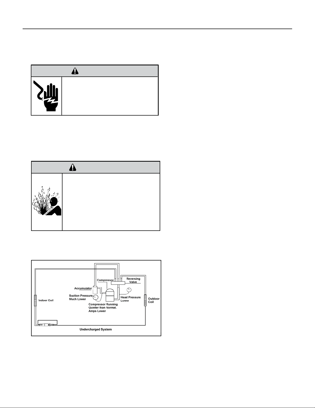
Undercharged Refrigerant Systems
An undercharged system will result in poor
performance (low pressures, etc.) in both the heating
and cooling cycle.
Whenever you service a unit with an undercharge of
refrigerant, always suspect a leak. The leak must be
repaired before charging the unit.
To check for an undercharged system, turn the unit
on, allow the compressor to run long enough to
establish working pressures in the system (15 to 20
minutes).
During the cooling cycle you can listen carefully at
the exit of the metering device into the evaporator;
an intermittent hissing and gurgling sound indicates
a low refrigerant charge. Intermittent frosting and
thawing of the evaporator is another indication of a
low charge, however, frosting and thawing can also
be caused by insufcient air over the evaporator.
Checks for an undercharged system can be made at
the compressor. If the compressor seems quieter
than normal, it is an indication of a low refrigerant
charge.
A check of the amperage drawn by the compressor
motor should show a lower reading. (Check the
Unit Specication.) After the unit has run 10 to
15 minutes, check the gauge pressures. Gauges
connected to system with an undercharge will have
low head pressures and substantially low suction
pressures.
Figure 601 (Undercharged System)
25 PB
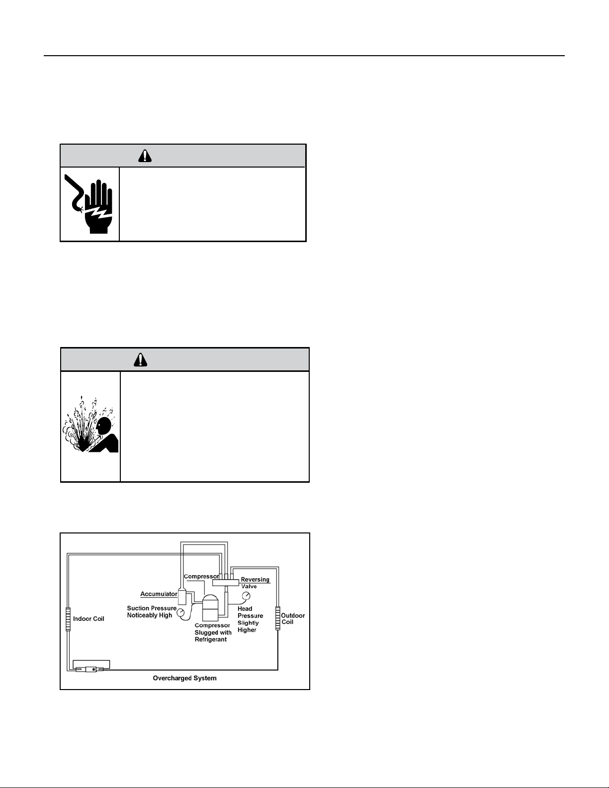
Overcharged Refrigerant Systems
Compressor amps will be near normal or higher.
Noncondensables can also cause these symptoms.
To conrm, remove some of the charge, if conditions
improve, system may be overcharged. If conditions
don’t improve, Noncondensables are indicated.
Whenever an overcharged system is indicated, always
make sure that the problem is not caused by air ow
problems. Improper air ow over the evaporator coil
may indicate some of the same symptoms as an over
charged system.
An overcharge can cause the compressor to fail, since
it would be “slugged” with liquid refrigerant.
The charge for any system is critical. When the
compressor is noisy, suspect an overcharge, when you
are sure that the air quantity over the evaporator coil is
correct. Icing of the evaporator will not be encountered
because the refrigerant will boil later if at all. Gauges
connected to system will usually have higher head
pressure (depending upon amount of over charge).
Suction pressure should be slightly higher.
Figure 602 (Overcharged System)
WARNING
RISK OF ELECTRIC SHOCK
Unplug and/or disconnect all electrical power
to the unit before performing inspections,
maintenances or service.
Failure to do so could result in electric shock,
serious injury or death.
WARNING
HIGH PRESSURE HAZARD
Sealed Refrigeration System contains refrigerant
and oil under high pressure.
Proper safety procedures must be followed,
and proper protective clothing must be worn
when working with refrigerants.
Failure to follow these procedures could
result in serious injury or death.
R-410A SEALED SYSTEM REPAIRS
26 PB
R-410A SEALED SYSTEM REPAIRS
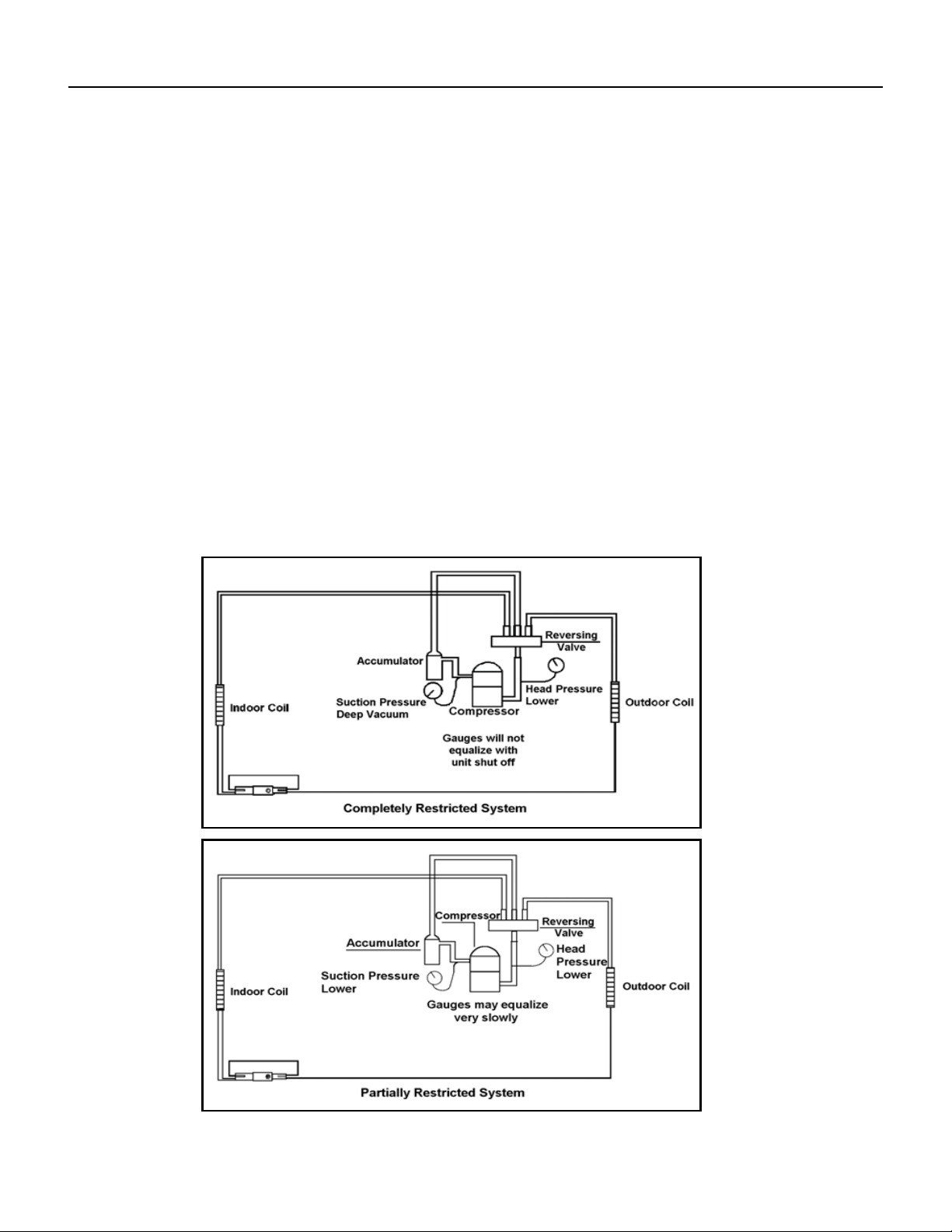
Restricted Refrigerant System
Troubleshooting a restricted refrigerant system can be difcult. The following procedures are the more common problems and
solutions to these problems. There are two types of refrigerant restrictions: Partial restrictions and complete restrictions.
A partial restriction allows some of the refrigerant to circulate through the system.
With a complete restriction there is no circulation of refrigerant in the system.
Restricted refrigerant systems display the same symptoms as a “low-charge condition.”
When the unit is shut off, the gauges may equalize very slowly.
Gauges connected to a completely restricted system will run in a deep vacuum. When the unit is shut off, the gauges will not
equalize at all.
A quick check for either condition begins at the evaporator. With a partial restriction, there may be gurgling sounds at the
metering device entrance to the evaporator. The evaporator in a partial restriction could be partially frosted or have an ice ball
close to the entrance of the metering device. Frost may continue on the suction line back to the compressor.
Often a partial restriction of any type can be found by feel, as there is a temperature difference from one side of the restriction to
the other.
With a complete restriction, there will be no sound at the metering device entrance. An amperage check of the compressor with
a partial restriction may show normal current when compared to the unit speci cation. With a complete restriction the current
drawn may be considerably less than normal, as the compressor is running in a deep vacuum (no load.) Much of the area of the
condenser will be relatively cool since most or all of the liquid refrigerant will be stored there.
Figure 603 (Restricted System)
27 PB
R-410A SEALED SYSTEM REPAIRS
Sealed System Method of Charging/ Repairs
BURN HAZARD
Proper safety procedures must be followed,
and proper protective clothing must be worn
when working with a torch.
Failure to follow these procedures could
result in moderate or serious injury.
WARNING
FREEZE HAZARD
Proper safety procedures must be followed,
and proper protective clothing must be worn
when working with liquid refrigerant.
Failure to follow these procedures could
result in minor to moderate injury.
CAUTION
The acceptable method for charging the sealed system is the Weighed in Charge Method. The weighed in charge
method is applicable to all units. It is the preferred method to use, as it is the most accurate.
The weighed in method should always be used whenever a charge is removed from a unit such as for a leak
repair, compressor replacement, or when there is no refrigerant charge left in the unit. To charge by this method,
requires the following steps:
1. Install a piercing valve to remove refrigerant from the sealed system. (Piercing valve must be removed from
the system before recharging.)
2. Recover Refrigerant in accordance with EPA regulations.
3. Install a process tube to sealed system.
4. Make necessary repairs to system.
5. Evacuate system to 200 microns or less.
6. Weigh in refrigerant with the property quantity of R-410A refrigerant.
7. Start unit, and verify performance.
8. Crimp the process tube and solder the end shut.
28 PB
Metering Device - Capillary Tube Systems
All units are equipped with capillary tube metering devices. Checking for restricted capillary tubes.
1. Connect pressure gauges to unit.
2. Start the unit in the cooling mode. If after a few minutes of operation the pressures are normal, the check valve and the
cooling capillary are not restricted.
3. Switch the unit to the heating mode and observe the gauge readings after a few minutes running time. If the system
pressure is lower than normal, the heating capillary is restricted.
4. If the operating pressures are lower than normal in both the heating and cooling mode, the cooling capillary is restricted.
Check Valve
A unique two-way check valve is used on the reverse cycle heat pumps. It is pressure operated and used to direct the ow of
refrigerant through a single lter drier and to the proper capillary tube during either the heating or cooling cycle.
NOTE: The slide (check) inside the valve is made of teon. Should it become necessary to replace the check valve, place a wet
cloth around the valve to prevent overheating during the brazing operation.
CHECK VALVE OPERATION
In the cooling mode of operation, high pressure liquid enters
the check valve forcing the slide to close the opposite port
(liquid line) to the indoor coil. Refer to refrigerant ow chart.
This directs the refrigerant through the lter drier and
cooling capillary tube to the indoor coil.
In the heating mode of operation, high pressure refrigerant
enters the check valve from the opposite direction, closing
the port (liquid line) to the outdoor coil. The ow path of
the refrigerant is then through the lter drier and heating
capillary to the outdoor coil.
Failure of the slide in the check valve to seat properly in
either mode of operation will cause ooding of the cooling
coil. This is due to the refrigerant bypassing the heating or
cooling capillary tube and entering the liquid line.
COOLING MODE
In the cooling mode of operation, liquid refrigerant from condenser (liquid line) enters the cooling check valve forcing the
heating check valve shut. The liquid refrigerant is directed into the liquid dryer after which the refrigerant is metered through
cooling capillary tubes to evaporator. (Note: liquid refrigerant will also be directed through the heating capillary tubes in a
continuous loop during the cooling mode).
HEATING MODE
In the heating mode of operation, liquid refrigerant from the indoor coil enters the heating check valve forcing the cooling
check valve shut. The liquid refrigerant is directed into the liquid dryer after which the refrigerant is metered through the
heating capillary tubes to outdoor coils. (Note: liquid refrigerant will also be directed through the cooling capillary tubes in a
continuous loop during the heating mode).
COMPONENT TESTING
Hermetic Components Check
BURN HAZARD
Proper safety procedures must be followed,
and proper protective clothing must be worn
when working with a torch.
Failure to follow these procedures could
result in moderate or serious injury.
WARNING
WARNING
CUT/SEVER HAZARD
Be careful with the sharp edges and corners.
Wear protective clothing and gloves, etc.
Failure to do so could result in serious injury.
One-way Check Valve
(Heat Pump Models)
Figure 701 (Check Valve)
29 PB
COMPONENT TESTING
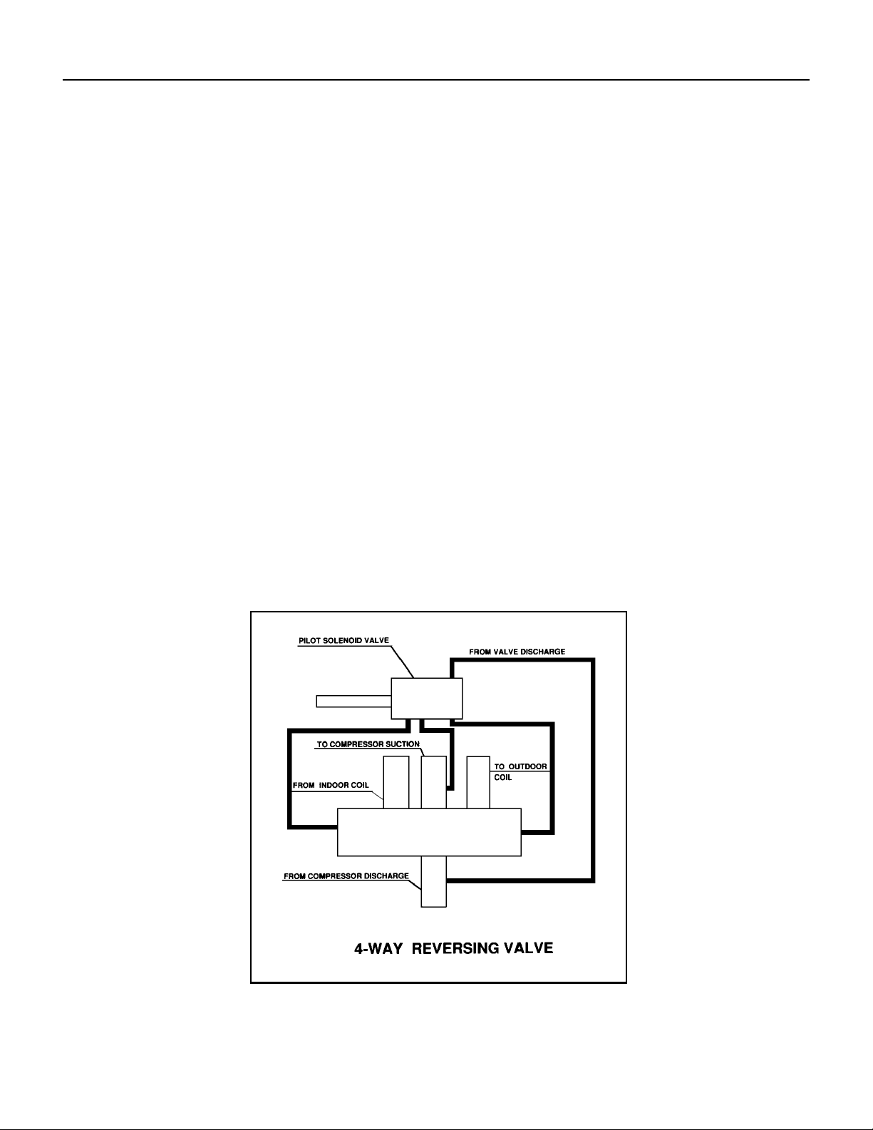
Reversing valve description and operation
The Reversing Valve controls the direction of refrigerant ow to the indoor and outdoor coils. It consists of a
pressure-operated, main valve and a pilot valve actuated by a solenoid plunger. The solenoid is energized during
the heating cycle only. The reversing valves used in the RAC system is a 2-position, 4-way valve.
The single tube on one side of the main valve body is the high-pressure inlet to the valve from the compressor.
The center tube on the opposite side is connected to the low pressure (suction) side of the system. The other two
are connected to the indoor and outdoor coils. Small capillary tubes connect each end of the main valve cylinder
to the “A” and “B” ports of the pilot valve. A third capillary is a common return line from these ports to the suction
tube on the main valve body. Four-way reversing valves also have a capillary tube from the compressor discharge
tube to the pilot valve.
The piston assembly in the main valve can only be shifted by the pressure differential between the high and low
sides of the system. The pilot section of the valve opens and closes ports for the small capillary tubes to the main
valve to cause it to shift.
A
B
Figure 702 (Reversing Valve)
30 PB
COMPONENT TESTING
Testing The Reversing Valve Solenoid Coil
The solenoid coil is an electromagnetic type coil mounted on the reversing valve and is energized during the
operation of the compressor in the heating cycle.
1. Turn off high voltage electrical power to unit.
2. Unplug line voltage lead from reversing valve coil.
3. Check for electrical continuity through the coil. If you do not have continuity replace the coil.
4. Check from each lead of coil to the copper liquid line as it leaves the unit or the ground lug. There should be no
continuity between either of the coil leads and ground; if there is, coil is grounded and must be replaced.
5. If coil tests okay, reconnect the electrical leads.
6. Make sure coil has been assembled correctly.
NOTE: Do not start unit with solenoid coil removed from valve, or do not remove coil after unit is in operation.
This will cause the coil to burn out.
Touch Test in Heating/Cooling Cycle
WARNING
ELECTRIC SHOCK HAZARD
Disconnect power to the unit before
servicing. Failure to follow this warning
could result in serious injury or death.
BURN HAZARD
Proper safety procedures must be followed,
and proper protective clothing must be worn
when working with a torch.
Failure to follow these procedures could
result in moderate or serious injury.
WARNING
WARNING
BURN HAZARD
Certain unit components operate at
temperatures hot enough to cause burns.
Proper safety procedures must be followed,
and proper protective clothing must be
worn.
Failure to follow these procedures could
result in minor to moderate injury.
The only denite indications that the slide is in the mid-position is if all three tubes on the suction side of the valve
are hot after a few minutes of running time.
NOTE: If both tubes shown as hot or cool are not the same corresponding temperature, refer to gure 703, then
the reversing valve is not shifting properly.
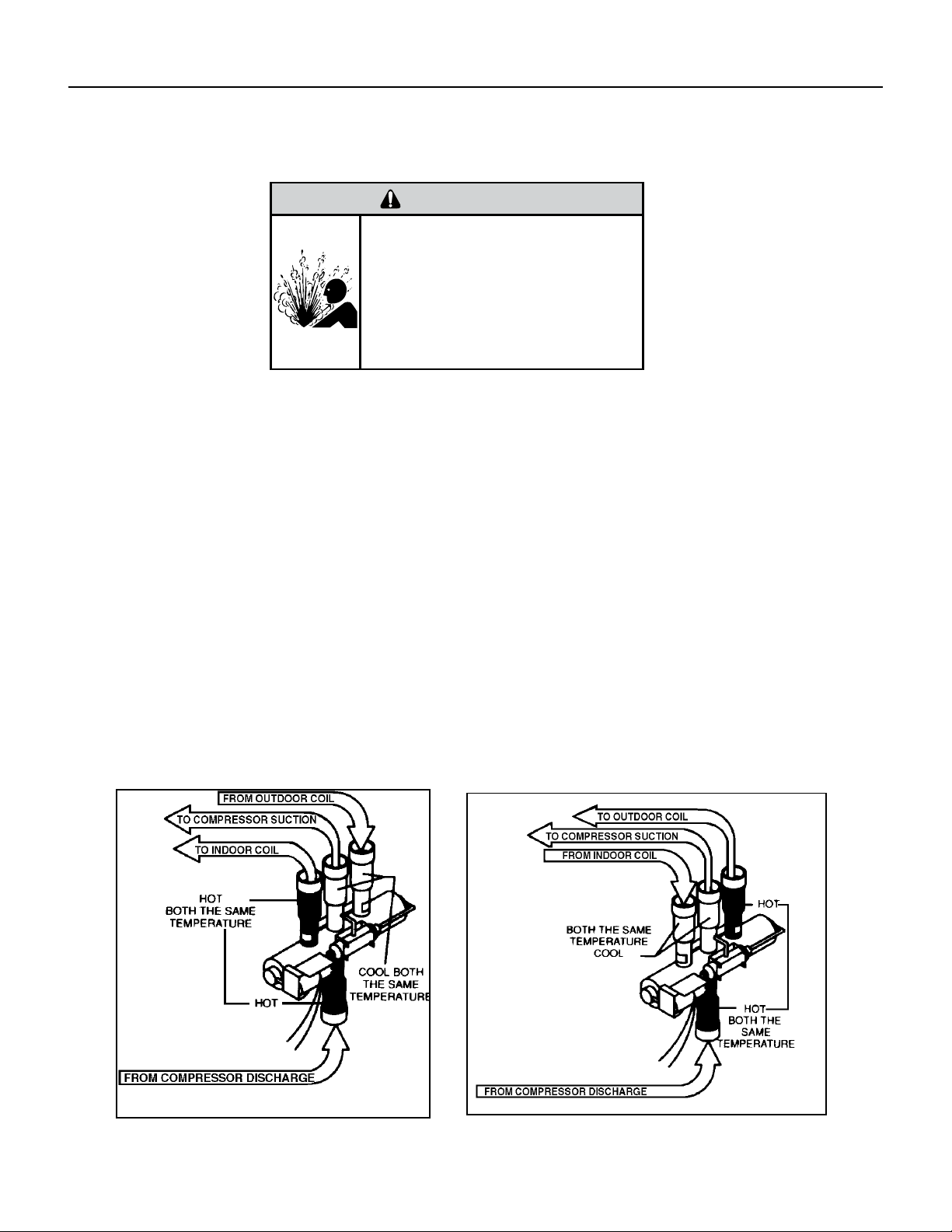
31 PB
NOTE: You must have normal operating pressures before the reversing valve can shift.
Check the operation of the valve by starting the system and switching the operation from “Cooling” to “Heating”
and then back to “Cooling”. Do not hammer on valve.
Occasionally, the reversing valve may stick in the heating or cooling position or in the mid-position.
When sluggish or stuck in the mid-position, part of the discharge gas from the compressor is directed back to the
suction side, resulting in excessively high suction pressure.
Should the valve fail to shift from coooling to heating, block the air ow through the outdoor coil and allow the
discharge pressure to build in the system. Then switch the system from heating to cooling.
If the valve is stuck in the heating position, block the air ow through the indoor coil and allow discharge pressure
to build in the system. Then switch the system from heating to cooling.
Should the valve fail to shift in either position after increasing the discharge pressure, replace the valve.
Dented or damaged valve body or capillary tubes can prevent the main slide in the valve body from shifting.
If you determing this is the problem, replace the reversing valve.
After all of the previous inspections and checks have been made and determined correct, then perform the
“Touch Test” on the reversing valve.
COMPONENT TESTING
Checking The Reversing Valve
Reversing Valve in Heating Mode
WARNING
HIGH PRESSURE HAZARD
Sealed Refrigeration System contains refrigerant
and oil under high pressure.
Proper safety procedures must be followed,
and proper protective clothing must be worn
when working with refrigerants.
Failure to follow these procedures could
result in serious injury or death.
Figure 703 (Checking The Reversing Valve)
32 PB
COMPONENT TESTING
Replace The Reversing Valve
WARNING
HIGH PRESSURE HAZARD
Sealed Refrigeration System contains refrigerant
and oil under high pressure.
Proper safety procedures must be followed,
and proper protective clothing must be worn
when working with refrigerants.
Failure to follow these procedures could
result in serious injury or death.
NOTICE
FIRE HAZARD
The use of a torch requires extreme care and proper
judgment. Follow all safety recommended precautions and
notice could result in moderate to serious property damage.
1. Install Process Tubes. Recover refrigerant from sealed system. PROPER HANDLING OF RECOVERED
REFRIGERANT ACCORDING TO EPA REGULATIONS IS REQUIRED.
2. Remove solenoid coil from reversing valve. If coil is to be reused, protect from heat while changing valve.
3. Unbraze all lines from reversing valve.
4. Clean all excess braze from all tubing so that they will slip into ttings on new valve.
5. Remove solenoid coil from new valve.
6. Protect new valve body from heat while brazing with plastic heat sink (Thermo Trap) or wrap valve body with
wet rag.
7. Fit all lines into new valve and braze lines into new valve.
WARNING
EXPLOSION HAZARD
The use of nitrogen requires a pressure
regulator. Follow all safety procedures and
wear protective safety clothing etc.
Failure to follow proper safety procedures
could result in serious injury or death.
8. Pressurize sealed system with a combination of R-410A and nitrogen and check for leaks, using a suitable
leak detector. Recover refrigerant per EPA guidelines.
9. Once the sealed system is leak free, install solenoid coil on new valve and charge the sealed system by
weighing in the proper amount and type of refrigerant as shown on rating plate. Crimp the process tubes and
solder the ends shut. Do not leave Schrader or piercing valves in the sealed system.
NOTE: When brazing a reversing valve into the system, it is of extreme importance that the temperature of the
valve does not exceed 250°F at any time.
Wrap the reversing valve with a large rag saturated with water. “Re-wet” the rag and thoroughly cool the valve
after each brazing operation of the four joints involved.
The wet rag around the reversing valve will eliminate conduction of heat to the valve body when brazing the line
connection.
33 PB
COMPONENT TESTING
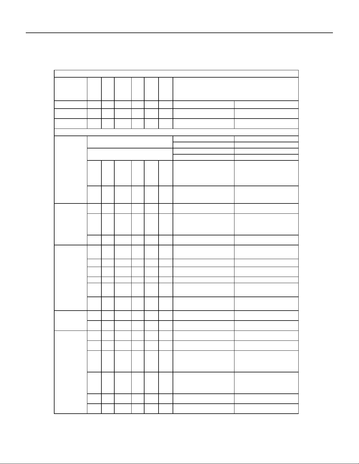
Touch Test Chart : To Service Reversing Valves
DISCHARGE TUBE
from Compressor
Tube to INSIDE
T
ube to INSIDE
Capillary Tube
RIGHT Pilot
Capillary Tube
Capillary Tube
LEFT Pilot
SUCTION
to Compressor
TUBE to
Compressor
Capillary Tube
COIL
14
COIL
NORMAL FUNCTION OF VALVE
VALVE
OPERATING
from Compressor
DISCHARGE TUBE
SUCTION TUBE
COIL
Tube to OUTSIDE
LEFT Pilot
RIGHT Pilot
CONDITION
NOTES:
1 2 3 4 6 5 POSSIBLE CAUSES
* TEMPERATURE OF VALVE BODY
** WARMER THAN VALVE BODY
Hot
Normal Cooling
CORRECTIONS
Cool
Cool
as (2)
Hot
as (1)
*TVB TVB
Normal Heating
Hot Cool
Hot
as (1)
Cool
as (2)
*TVB TVB
MALFUNCTION OF VALVE
Valve will not
to heat.
shift from cool
Check Electrical circuit and coil
Repair electrical circuit. No voltage to coil.
Replace coil. Defective coil.
Check refrigeration charge
Repair leak, recharge system. Low charge.
Pressure differential too high. Recheck system.
Hot Cool
Cool,
as (2)
Hot,
as (1)
Hot *TVB Pilot valve okay. Dirt in one bleeder hole.
Piston cup leak
Deenergize solenoid, raise head pressure,
reenergize solenoid to break dirt loose.
If unsuccessful, remove valve, wash
out. Check on air before installing. If no
movement, replace valve, add strainer to
discharge tube, mount valve horizontally.
Valve will not
Stop unit. After pressures equalize, restart
with solenoid energized. If valve shifts,
reattempt with compressor running. If still
no shift, replace valve.
shift from cool
to heat.
Hot Cool
Cool,
as (2)
Hot,
as (1)
*TVB *TVB Clogged pilot tubes.
Raise head pressure, operate solenoid to
free. If still no shift, replace valve.
Hot Cool
Cool,
as (2)
Hot,
as (1)
Hot Hot
Both ports of pilot open. (Back seat port
did not close).
Cool Warm
Raise head pressure, operate solenoid
to free
partially clogged port. If still no shift,
replace
valve.
Cool,
as (2)
Hot,
as (1)
*TVB Warm Defective Compressor. Replace compressor
Starts to shift
complete
reversal.
but does not
Hot Warm Warm Hot Hot *TVB
Check unit for correct operating pressures
and charge. Raise head pressure. If no
shift, use valve with smaller port.
Not enough pressure differential at start
of stroke or not enough fl ow to maintain
pressure differential.
Replace valve Body damage.
Hot Warm Warm Hot Hot Hot Both ports of pilot open.
Raise head pressure, operate solenoid. If
no shift, use valve with smaller ports.
Replace valve Body damage. Hot *TVB Hot Hot Hot Hot
Hot Hot
Raise head pressure, operate solenoid. If
no shift, use valve with smaller ports.
Hot Hot
Valve hung up at mid-stroke. Pumping
volume of compressor not suffi cient to
maintain reversal.
Hot Hot Both ports of pilot open.
Apparent
Raise head pressure, operate solenoid.
If no
shift, replace valve.
leap in heat-
ing.
Hot Cool
Hot,
as (1)
Cool,
as (2)
*TVB *TVB Piston needle on end of slide leaking.
Hot Cool
Operate valve several times, then recheck.
If excessive leak, replace valve.
Hot,
as (1)
Cool,
as (2)
**WVB **WVB Pilot needle and piston needle leaking.
Operate valve several times, then recheck.
If excessive leak, replace valve.
Will not shift
cool.
from heat to
Hot Cool
Hot,
as (1)
Cool,
as (2)
*TVB *TVB Pressure differential too high.
Clogged pilot tube.
Stop unit. Will reverse during equalization
period. Recheck system
Hot
Raise head pressure, operate solenoid to
free dirt. If still no shift, replace valve.
Cool
Hot,
as (1)
Cool,
as (2)
Hot *TVB Dirt in bleeder hole.
Hot Cool
Hot,
as (1)
Cool,
as (2)
Hot
Raise head pressure, operate solenoid.
Remove valve and wash out. Check on air
before reinstalling, if no movement, replace
valve. Add strainer to discharge tube.
Mount valve horizontally.
Piston cup leak. *TVB
Hot Cool
Hot,
as (1)
Stop unit. After pressures equalize, restart
with solenoid deenergized. If valve shifts,
reattempt with compressor running. If it
still will not reverse while running, replace
the valve.
Cool,
as (2)
Replace valve. Defective pilot. Hot Hot
Warm Cool
Warm,
as (1)
Cool,
as (2)
Warm *TVB Defective compressor. Replace compressor
Figure 704 (Touch Test Chart)
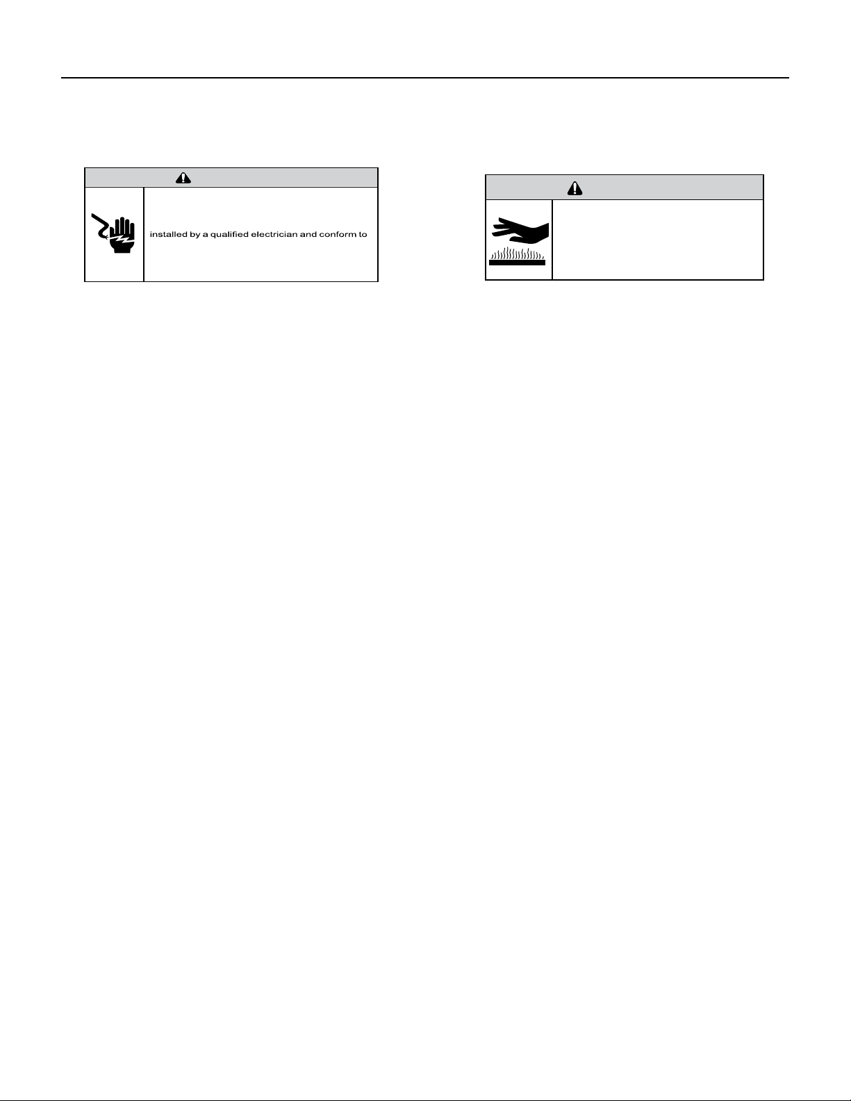
34 PB
COMPONENT TESTING
Compressor Checks
Locked Rotor Voltage (L.R.V.) Test
Locked rotor voltage (L.R.V.) is the actual voltage available at the compressor under a stalled condition.
Single Phase Connections
Disconnect power from unit. Using a voltmeter, attach one lead of the meter to the run “R” terminal on the compressor and the
other lead to the common “C” terminal of the com-pressor. Restore power to unit.
Determine L.R.V.
Start the compressor with the volt meter attached; then stop the unit. Attempt to restart the compressor within a couple
of seconds and immediately read the voltage on the meter. The compressor under these conditions will not start and will
usually kick out on overload within a few seconds since the pressures in the system will not have had time to equalize. Voltage
should be at or above minimum voltage of 197 VAC, as specied on the rating plate. If less than minimum, check for cause of
inadequate power supply; i.e., incorrect wire size, loose electrical connections, etc.
Amperage (L.R.A.) Test
The running amperage of the compressor is the most important of these readings. A running amperage higher than that
indicated in the performance data indicates that a problem exists mechanically or electrically.
Single Phase Running and L.R.A. Test
NOTE: Consult the specication and performance section for running amperage. The L.R.A. can also be found on the rating
plate.
Select the proper amperage scale and clamp the meter probe around the wire to the “C” terminal of the compressor.
Turn on the unit and read the running amperage on the meter. If the compressor does not start, the reading will indicate the
locked rotor amperage (L.R.A.).
Overloads
The compressor is equipped with either an external or internal overload which senses both motor amperage and winding
temperature. High motor temperature or amperage heats the overload causing it to open, breaking the common circuit within
the compressor. Heat generated within the compressor shell, usually due to recycling of the motor, is slow to dissipate. It may
take anywhere from a few minutes to several hours for the overload to reset.
Checking the Overloads
External Overloads
With power off, remove the leads from compressor terminals. If the compressor is hot, allow the overload to cool before
starting check. Using an ohmmeter, test continuity across the terminals of the external overload. If you do not have continuity;
this indicates that the overload is open and must be replaced.
Interrnal Overloads
Some model compressors are equipped with an internal overload. The overload is embedded in the motor windings to sense
the winding temperature and/or current draw. The overload is connected in series with the common motor terminal.
Should the internal temperature and/or current draw become excessive, the contacts in the overload will open, turning off the
compressor. The overload will automatically reset, but may require several hours before the heat is dissipated.
Checking the Internal Overload
1. With no power to unit, remove the leads from the compressor terminals.
2. Using an ohmmeter, test continuity between terminals
C-S and C-R. If no continuity, the compressor overload is open and the compressor must be replaced.
WARNING
ELECTRIC SHOCK HAZARD
Turn off electric power before service or
installation.
All electrical connections and wiring MUST be
the National Electrical Code and all local codes
which have jurisdiction.
Failure to do so can result in personal injury or
death.
BURN HAZARD
Proper safety procedures must be followed,
and proper protective clothing must be worn
when working with a torch.
Failure to follow these procedures could
result in moderate or serious injury.
WARNING
35 PB
WARNING
ELECTRIC SHOCK HAZARD
Turn off electric power before service or
installation. Extreme care must be used, if it
becomes necessary to work on equipment with
power applied.
Failure to do so could result in serious injury or
death.
Single Phase Resistance Test
Remove the leads from the compressor terminals and set the ohmmeter on the lowest scale (R x 1).
Touch the leads of the ohmmeter from terminals common to start (“C” to “S”). Next, touch the leads of the ohmmeter from
terminals common to run (“C” to “R”).
Add values “C” to “S” and “C” to “R” together and check resistance from start to run terminals (“S” to “R”). Resistance “S” to
“R” should equal the total of “C” to “S” and “C” to “R.”
In a single phase PSC compressor motor, the highest value will be from the start to the run connections (“S” to “R”). The next
highest resistance is from the start to the common connections (“S” to “C”). The lowest resistance is from the run to common.
(“C” to “R”) Before replacing a compressor, check to be sure it is defective.
GROUND TEST
Use an ohmmeter set on its highest scale. Touch one lead to the compressor body (clean point of contact as a good connection
is a must) and the other probe in turn to each compressor terminal. If a reading is obtained the compressor is grounded and
must be replaced.
Check the complete electrical system to the compressor and compressor internal electrical system, check to be certain that
compressor is not out on internal overload.
Complete evaluation of the system must be made whenever you suspect the
compressor is defective. If the compressor has been operating for sometime, a
careful examination must be made to determine why the compressor failed.
Many compressor failures are caused by the following conditions:
1.Improper air ow over the evaporator.
2.Overcharged refrigerant system causing liquid to be returned to the
compressor.
3.Restricted refrigerant system.
4.Lack of lubrication.
5.Liquid refrigerant returning to compressor causing oil to be washed out of
bearings.
6.Noncondensables such as air and moisture in the system. Moisture is
extremely destructive to a refrigerant system.
7.Capacitor.
CHECKING COMPRESSOR EFFICIENCY
The reason for compressor inefciency is normally due to broken or damaged suction and/or discharge valves, reducing the
ability of the compressor to pump refrigerant gas.
This condition can be checked as follows:
1. Install a piercing valve on the suction and discharge or liquid process tube.
2. Attach gauges to the high and low sides of the system.-
3. Start the system and run a “cooling or heating performance test.” If test shows:
A. Below normal high side pressure
B. Above normal low side pressure
C. Low temperature difference across coil
The compressor valves are faulty - replace the compressor.
WARNING
HIGH PRESSURE HAZARD
Sealed Refrigeration System contains refrigerant
and oil under high pressure.
Proper safety procedures must be followed,
and proper protective clothing must be worn
when working with refrigerants.
Failure to follow these procedures could
result in serious injury or death.
Figure 705 (Resistance Chart)
COMPONENT TESTING
Compressor Checks
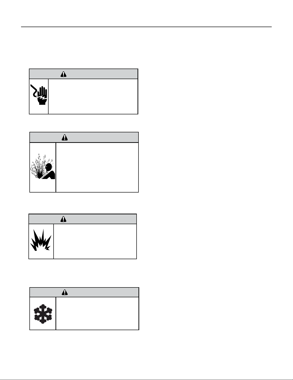
36 PB
COMPONENT TESTING
Compressor Replacement
WARNING
ELECTRIC SHOCK HAZARD
Turn off electric power before service or
installation. Extreme care must be used, if it
becomes necessary to work on equipment with
power applied.
Failure to do so could result in serious injury or
death.
WARNING
HIGH PRESSURE HAZARD
Sealed Refrigeration System contains refrigerant
and oil under high pressure.
Proper safety procedures must be followed,
and proper protective clothing must be worn
when working with refrigerants.
Failure to follow these procedures could
result in serious injury or death.
1. Be certain to perform all necessary electrical and refrigeration
tests to be sure the compressor is actually defective before
replacing.
2. Recover all refrigerant from the system though the process
tubes. PROPER HANDLING OF RECOVERED REFRIGERANT
ACCORDING TO EPA REGULATIONS IS REQUIRED. Do not use
gauge manifold for this purpose if there has been a burnout. You
will contaminate your manifold and hoses. Use a Schrader valve
adapter and copper tubing for burnout failures.
3.After all refrigerant has been recovered, disconnect suction and
discharge lines from the compressor and remove compressor. Be
certain to have both suction and discharge process tubes open to
atmosphere.
4.Carefully pour a small amount of oil from the suction stub of the
defective compressor into a clean container.
5.Using an acid test kit (one shot or conventional kit), test the oil
for acid content according to the instructions with the kit.
6.If any evidence of a burnout is found, no matter how slight, the
system will need to be cleaned up following proper procedures.
7.Install the replacement compressor.
8. Pressurize with a combination of R-410A and nitrogen and leak
test all connections with an electronic or Halide leak detector.
Recover refrigerant and repair any leaks found.
8a. If leak detector is unavailable remove all refrigerant from
system and pressurize with nitrogen to 350 psi. Check that system
holds pressure.
Repeat Step 8 to insure no more leaks are present
9. Evacuate the system with a good vacuum pump capable
of a nal vacuum of 200 microns or less. The system should
be evacuated through both liquid line and suction line gauge
ports. While the unit is being evacuated, seal all openings on
the defective compressor. Compressor manufacturers will void
warranties on units received not properly sealed. Do not distort
the manufacturers tube connections.
10. Recharge the system with the correct amount of refrigerant.
The proper refrigerant charge will be found on the unit rating
plate. The use of an accurate measuring device, such as a
charging cylinder, electronic scales or similar device is necessary.
WARNING
EXPLOSION HAZARD
The use of nitrogen requires a pressure
regulator. Follow all safety procedures and
wear protective safety clothing etc.
Failure to follow proper safety procedures
could result in serious injury or death.
FREEZE HAZARD
Proper safety procedures must be followed,
and proper protective clothing must be worn
when working with liquid refrigerant.
Failure to follow these procedures could
result in minor to moderate injury.
CAUTION
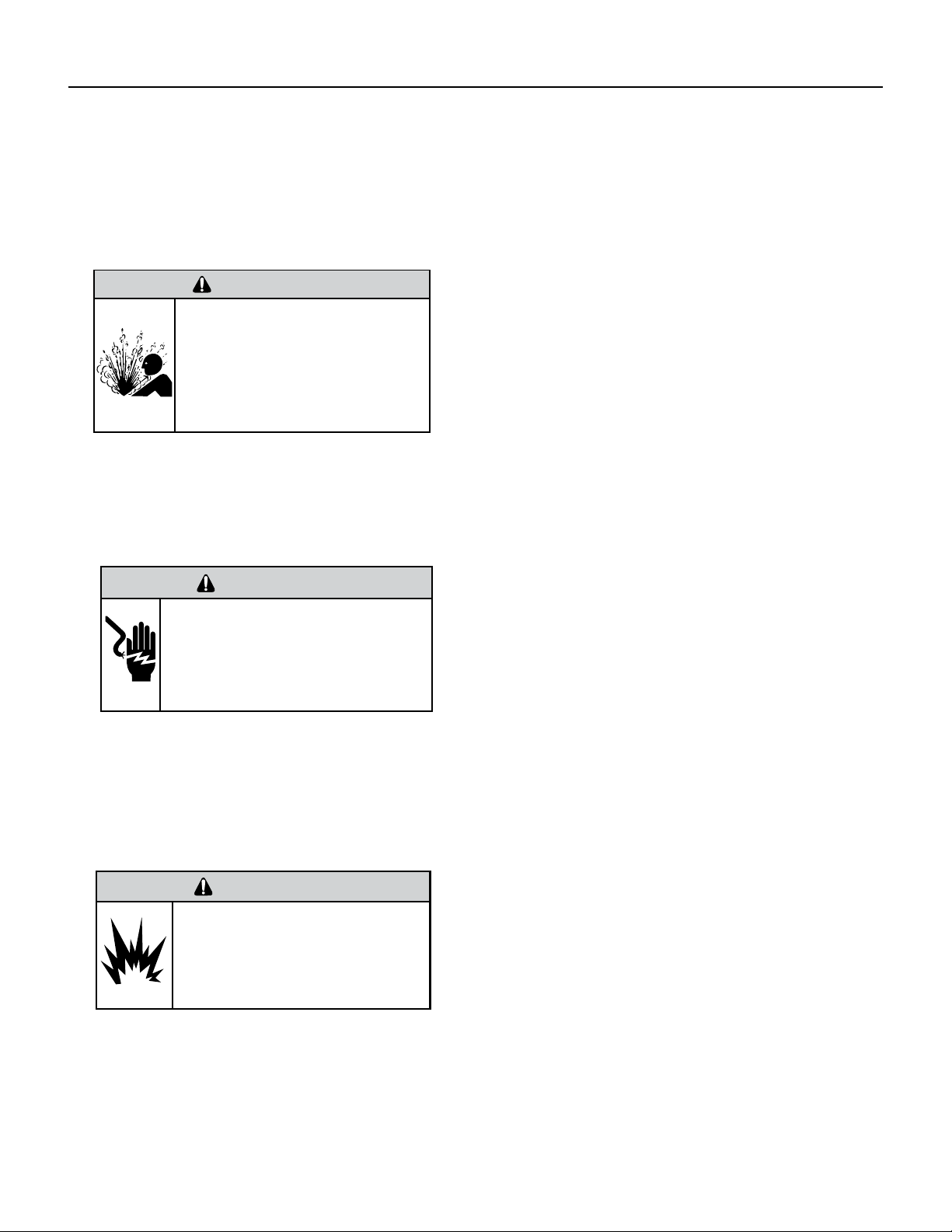
37 PB
COMPONENT TESTING
Compressor Replacement -Special Procedure in Case of Compressor Burnout
WARNING
HIGH PRESSURE HAZARD
Sealed Refrigeration System contains refrigerant
and oil under high pressure.
Proper safety procedures must be followed,
and proper protective clothing must be worn
when working with refrigerants.
Failure to follow these procedures could
result in serious injury or death.
WARNING
ELECTRIC SHOCK HAZARD
Turn off electric power before service or
installation. Extreme care must be used, if it
becomes necessary to work on equipment with
power applied.
Failure to do so could result in serious injury or
death.
WARNING
EXPLOSION HAZARD
The use of nitrogen requires a pressure
regulator. Follow all safety procedures and
wear protective safety clothing etc.
Failure to follow proper safety procedures
could result in serious injury or death.
1. Recover all refrigerant and oil from the system.
2. Remove compressor, capillary tube and lter drier from the
system.
3. Flush evaporator condenser and all connecting tubing with dry
nitrogen or equivalent. Use approved ushing agent to remove all
contamination from system. Inspect suction and discharge line for
carbon deposits. Remove and clean if necessary. Ensure all acid is
neutralized.
4. Reassemble the system, including new drier strainer and capillary
tube.
5. Pressurize with a combination of R-410A and nitrogen and leak
test all connections with an electronic or Halide leak detector.
Recover refrigerant and repair any leaks found.
5a. If leak detector is unavailable remove all refrigerant from system
and pressurize with nitrogen to 350 psi. Check that system holds
pressure.
Repeat Step 5 to insure no more leaks are present
6. Evacuate the system with a good vacuum pump capable of a nal
vacuum of 200 microns or less. The system should be evacuated
through both liquid line and suction line gauge ports. While the unit
is being evacuated, seal all openings on the defective compressor.
Compressor manufacturers will void warranties on units received not
properly sealed. Do not distort the manufacturers tube connections.
7. Recharge the system with the correct amount of refrigerant. The
proper refrigerant charge will be found on the unit rating plate. The
use of an accurate measuring device, such as a charging cylinder,
electronic scales or similar device is necessary.
ROTARY AND SCROLL COMPRESSOR SPECIAL TROUBLESHOOTING
AND SERVICE
Troubleshooting and servicing rotary compressors is basically
the same as on the reciprocating compressor with only one main
exception:
NEVER, under any circumstances, liquid charge a rotary-compressor
through the LOW side. Doing so would cause permanent damage to
the new compressor. Use a charging adapter.
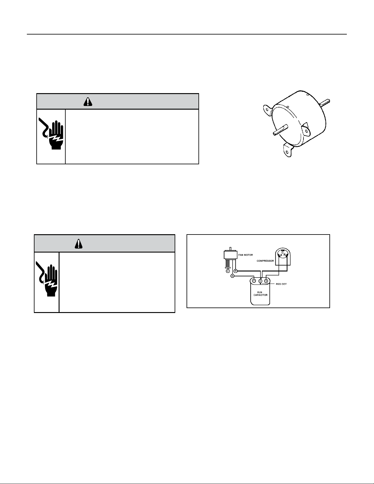
38 PB
COMPONENTS TESTING
Fan Motor
A single phase permanent split capacitor motor is used to drive the evaporator blower and condenser fan. A self-
resetting overload is located inside the motor to protect against high temperature and high amperage conditions.
WARNING
ELECTRIC SHOCK HAZARD
Turn off electric power before service or
installation. Extreme care must be used, if it
becomes necessary to work on equipment with
power applied.
Failure to do so could result in serious injury or
death.
Figure 23
Blower/Fan Motor
Blower / Fan Motor Test
1. Determine that capacitor is serviceable.
2. Disconnect fan motor wires from fan speed switch or system switch.
3. Apply “live” test cord probes on black wire and common terminal of capacitor. Motor should run at high speed.
4. Apply “live” test cord probes on red wire and common terminal of capacitor. Motor should run at low speed.
5. Apply “live” test cord probes on each of the remaining wires from the speed switch or system switch to test intermediate
speeds. If the control is in the “MoneySaver” mode and the thermostat calls for cooling, the fan will start - then stop after
approximately 2 minutes; then the fan and compressor will start together approximately 2 minutes later.
Capacitors
WARNING
ELECTRIC SHOCK HAZARD
Turn off electric power before service or
installation. Extreme care must be used, if it
becomes necessary to work on equipment with
power applied.
Failure to do so could result in serious injury or
death.
Many motor capacitors are internally fused. Shorting the terminals will blow the fuse, ruining the capacitor. A 20,000 ohm 2
watt resistor can be used to discharge capacitors safely. Remove wires from capacitor and place resistor across terminals.
When checking a dual capacitor with a capacitor analyzer or ohmmeter, both sides must be tested.
Capacitor Check with Capacitor Analyzer
The capacitor analyzer will show whether the capacitor is “open” or “shorted.” It will tell whether the capacitor is within its
micro farads rating and it will show whether the capacitor is operating at the proper power-factor percentage. The instrument
will automatically discharge the capacitor when the test switch is released.
Capacitor Connections
The starting winding of a motor can be damaged by a shorted and grounded running capacitor. This damage usually can be
avoided by proper connection of the running capacitor terminals.
From the supply line on a typical 230 volt circuit, a 115 volt potential exists from the “R” terminal to ground through a possible
short in the capacitor. However, from the “S” or start terminal, a much higher potential, possibly as high as 400 volts, exists
because of the counter EMF generated in the start winding. Therefore, the possibility of capacitor failure is much greater when
the identied terminal is connected to the “S” or start terminal. The identied terminal should always be connected to the
supply line, or “R” terminal, never to the “S” terminal.
When connected properly, a shorted or grounded running capacitor will result in a direct short to ground from the “R”
terminal and will blow the line fuse. The motor protector will protect the main winding from excessive temperature.
Dual Rated Run Capacitor Hook-up
Figure 706 (Blower)
Figure 707 Dual Rated Capacitor Hook-Up

39 PB
ROOM AIR CONDITIONER UNIT PERFORMANCE TEST DATA SHEET
JOB NAME______________________ TECH’S NAME_________________________
DATE___________ MODEL#_______________ SERIAL #______________________
CHECK THE INSTALLATION ACCEPTABLE NOT ACCEPTABLE
YES NO
IS A CHASIS GASKET INSTALLED? _____ ____
IS THE FRESH / EXHAUST AIR VENT OPEN? _____ ____
IS A FRIEDRICH SLEEVE INSTALLED? _____ ____
IS A FRIEDRICH OUTDOOR GRILLE INSTALLED? _____ ____
IS MAINTENANCE BEING PERFORMED? _____ ____
ELECTRICAL
LINE VOLTAGE (STATIC) _____ VOLTS
START UP VOLTAGE _____ VOLTS
AMPERAGE DRAW (COOL) _____ AMPS
AMPERAGE DRAW (HEAT) _____ AMPS
COMPRESSOR
LOCKED ROTOR AMPS _____ AMPS
RUNNING AMPERAGE DRAW _____ AMPS
INDOOR CONDITIONS
INDOOR AMBIENT TEMPERATURE _____ F
RELATIVE HUMIDITY (RH) INDOOR _____%
DISCHARGE AIR TEMPERATURE (INDOOR)(COOL) _____F
DISCHARGE AIR TEMPERATURE (INDOOR)(HEAT) _____F
RETURN AIR TEMPERATURE (INDOOR)(COOL) _____F
RETURN AIR TEMPERATURE (INDOOR) (HEAT) _____F
OUTDOOR TEMPERATURE
OUTDOOR AMBIENT TEMPERATURE _____F
RH OUTDOOR RELATIVE HUMIDITY _____%
DISCHARGE AIR TEMPERATURE (OUTDOOR)(COOL) _____F
DISCHARGE AIR TEMPERATURE (OUTDOOR)(HEAT) _____F
INTAKE AIR TEMPERATURE (OUTDOOR)(COOL) _____F
INTAKE AIR TEMPERATURE (OUTDOOR)(HEAT) _____F
COOLING OR HEATING AREA
AREA W______ * L_______ = FEET SQUARED
FOR A GENERAL GUIDE REFER TO SIZING GUIDE TO THE RIGHT
FOR EXACT LOAD CALCULATIONS CONSULT MANUAL J OR M.
COOLING SIZING
GUIDE
AREA TO BE
CONDITIONED
IN SQ. FT.
APPROXIMATE
COOLING BTU
REQUIRED
100 - 150 5000
150 - 250 6000
250 - 300 7000
300 - 350 8000
350 - 400 9000
400 - 450 10000
450 - 550 12000
550 - 700 14000
700 - 1000 18000
1000 - 1200 21000
1200 - 1400 23000
1400 - 1500 24000
1500 - 2000 30000
2000 - 2500 34000
Guide based on normal
room insulation, average
number of sun exposed
windows and two person
occupancy.
1. If heavily shaded, reduce
cooling Btus required by 10%
2. If very sunny, increase cool-
ing Btus required by 10%
3. Add 500 Btus per person over
2 people
4. Add 4,000 Btus if the area is
a kitchen
TROUBLESHOOTING
Figure 713 (Test Data Sheet)
Figure 714 (Cooling Sizing Guide)
40 PB
TROUBLESHOOTING
Product Does Not Operate At All
Figure 715
Product does not operate at all.
Power supply voltage check
Connector contact check
PCB assy check
Power input voltage on
driving load terminal.
Display PCB connector
Power transformer output voltage
Product input voltage
AC about 12±3V
41 PB
Figure 716
TROUBLESHOOTING
Indoor Fan Does Not Operate At All
Indoor fan does not operate at all.
Connector contact
Motor detail check
Motor - related parts
Operation mode check
PCB assy check
Check:
Motor driving circuit
Relay output
Check:
Motor outputconnector
Motor capacitor
Replace motor or
PCB ass’y
Check:
Fan(Blower)fixedstate
Fan(Blower)contact
state
42 PB
TROUBLESHOOTING
Compressor Or Outdoor Fan Does Not Operate At All
Figure 716
Compressor or outdoor fan does not operate at all.
Re-input after power of f
Set the desired temperature of remote controller to be lower by 2°C or
over than room temperature, and start the cooling operation.
Does not operate at all.
Repeat running/stopping
at a short time period.
Temperature sensor
open/short check
Thermistor and evaporator
surface contact check.-
Clearance is needed (5mm).
Connector check
(Contact & power)
Connector check
(Contact & power)
Disconnection/short
circuit check of
connecting wire
OLP/High pressure
switch/Low pressure
switch check
Electric wire connection
check for outdoor side
Operation mode
(dehumidifying) check
Compressor & motor
detail check
PCB assy check
Check:
Temperature sensing circuit
Relay output
Insulation resistance
Coil resistance
Capacitor capacity
Compressor OLP
43 PB
TROUBLESHOOTING
Display E1 or E2
Figure 716
Connector contact
Display E1 and E2
Check the wire connection of indoor
temperature sensor assembly.
Replace sensor
Replace main PCB
44 PB
WIRING DIAGRAMS
Chill Premier CCF
Figure 801
Models: CCF05A10A CCF06A10A CCF08A10A
CCF10A10A CCF12A10A
E
45 PB
WIRING DIAGRAMS
Chill Premier CCW
Models: CCW06B10A . CCW24B30A
Figure 802
46 PB
WIRING DIAGRAMS
Chill Premier CCW
CCW08B10A
Models:
Models: CCW10B10A.CCW12B10A.CCW15B10A
Figure 803
47 PB
WIRING DIAGRAMS
Chill Premier
CCW10B10A, CCW12B10A, CCW15B10A, CCW18B30A
Models:
Models: CCW10B10A.CCW12B10A.CCW15B10A
Figure 804
48 PB
WIRING DIAGRAMS
Chill Premier CEW
CEW08B11A
Figure 805
49 PB
WIRING DIAGRAMS
Chill Premier CEW
CEW12B33A, CEW18B33A
Figure 806
50 PB
WIRING DIAGRAMS
Chill Premier CEW
CEW24B33A
Figure 807
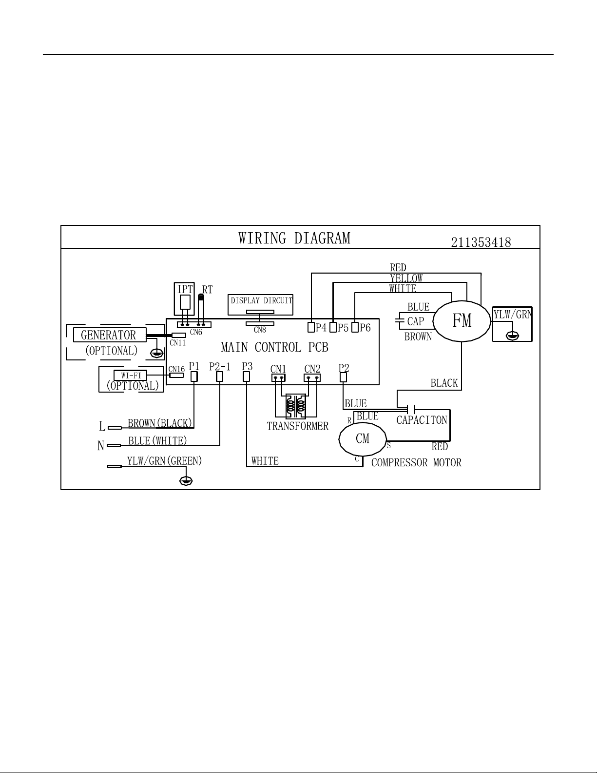
51 PB
WIRING DIAGRAMS
Unit
UCT08A10A, UCT10A10A, UCT12A10A, UCT10A30A, UCT12A30A, UCT14A30A
Figure 808
Models: UCT08A10A UCT10A10A UCT12A10A
UCT10A30A UCT12A30A UCT14A30A
E
Models: UET10A33A UET12A33A UET14A33A UET08A11A
E
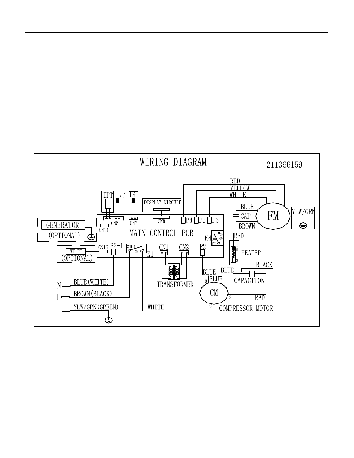
52 PB
WIRING DIAGRAMS
Unit
UET10A33A, UET12A33A, UET14A33A, UET08A11A
Models: UCT08A10A UCT10A10A UCT12A10A
UCT10A30A UCT12A30A UCT14A30A
E
Models: UET10A33A UET12A33A UET14A33A UET08A11A
E
Figure 809
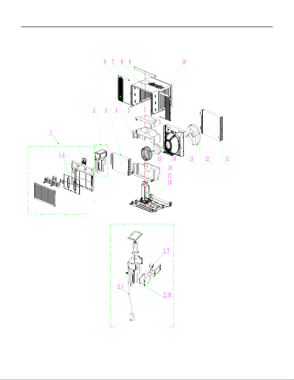
53 PB
PARTS CATALOG
Chill Premier Models: CCW06B10A CCW08B10A CCW10B10A CCW12B10A
FIgure 901
54 PB
PARTS CATALOG
Chill Premier Models: CCW06B10A CCW08B10A CCW10B10A CCW12B10A
FIgure 901
ITEM PART
NUMBER
PART DESCRIPTION USED ON MODEL QTY
1 68000163 41106-003745_UI - Front Panel
Assembly
CCW06B10A, CCW08B10A,CCW10B10A 1
1A 68000264 41106-003738_UI - Front Panel
Assembly
CCW12B10A 1
1.6 68000175 41507-000136 - Air Filter CCW06B10A, CCW08B10A, CCW10B10A, CCW12B10A 1
2 68000181 41505-000230 - Electrical Box
Assembly
CCW06B10A, CCW08B10A, CCW10B10A, CCW12B10A 1
2.1 68000183 22007-000068_UI - Power Supply
Cord
CCW06B10A, CCW08B10A 1
2.1A 68000256 22007-000069 - Power Supply
Cord
CCW10B10A, CCW12B10A 1
2.7 68000197 10502-100032_UI - Transformer CCW06B10A, CCW08B10A, CCW10B10A , CCW12B10A 1
2.10 68000203 31502-000014_UI - Main pcb CCW06B10A, CCW08B10A, CCW10B10A, CCW12B10A 1
3 68000205 92011-005038 - Evaporator CCW06B10A 1
3A 68000245 92011-004873 - Evaporator CCW08B10A 1
3B 68000259 92011-005089 - Evaporator CCW10B10A 1
3C 68000267 92011-004459 - Evaporator CCW12B10A 1
4 68000207 41504-000140_UI - Middle Vortex
Shell
CCW06B10A, CCW08B10A, CCW10B10A , CCW12B10A 1
5 68000209 41504-000134_UI - Up Vortex
Shell
CCW06B10A, CCW08B10A, CCW10B10A, CCW12B10A 1
6 68000211 41509-000049 - Adjustable shade CCW06B10A, CCW08B10A, CCW10B10A, CCW12B10A 1
7 68000221 41509-000053 - left Adjustable
shade rail
CCW06B10A, CCW08B10A, CCW10B10A, CCW12B10A 1
8 68000222 41508-000016_UI - Cabinet CCW06B10A, CCW08B10A, CCW10B10A, CCW12B10A 1
9 68000223 41509-000023 - Up Adjustable
shade rail
CCW06B10A, CCW08B10A, CCW10B10A, CCW12B10A 1
10 68000224 41509-000051 - Right Adjustable
shade rail
CCW06B10A, CCW08B10A, CCW10B10A, CCW12B10A 1
11 68000205 92011-005038 - Condenser CCW08B10A, CCW10B10A 1
11A 68000260 92011-005088 - Condenser CCW10B10A 1
11B 68000268 92011-004641 - Condenser CCW12B10A 1
12 68000225 41503-000007_UI - Propeller Fan CCW06B10A, CCW08B10A, CCW10B10A, CCW12B10A 1
13 68000226 41504-000192_UI - Back
Surround Plate
CCW06B10A, CCW12B10A 1
13A 68000250 41504-000193 - Back Surround
Plate
CCW08B10A, CCW10B10A 1
14 68000227 22001-000427_UI - Fan Motor CCW06B10A, CCW08B10A 1
14A 68000261 22001-000394 - Fan Motor CCW10B10A, CCW12B10A 1
15 68000228 41503-000010_UI - Centrifugal
Fan
CCW06B10A, CCW08B10A, CCW10B10A, CCW12B10A 1
16 68000229 41504-000173_UI - Water
drainage pan
CCW06B10A, CCW08B10A, CCW10B10A, CCW12B10A 1
55 PB
PARTS CATALOG
Chill Premier Models: CCW06B10A CCW08B10A CCW10B10A CCW12B10A
ITEM PART
NUMBER
PART DESCRIPTION USED ON MODEL QTY
17 68000230 92014-000599 - Compressor CCW06B10A 1
17A 68000254 92014-000259 - Compressor CCW08B10A 1
17B 68000262 92014-000305 - Compressor CCW10B10A 1
17C 68000270 92014-000262 - Compressor CCW12B10A 1
18 68000231 41502-000042 - Base CCW06B10A, CCW08B10A, CCW10B10A, CCW12B10A 1
-19 68000232 10104-100026 - Sensor CCW06B10A, CCW08B10A, CCW10B10A, CCW12B10A 1
-20 68000233 31502-000025 - Display PCB CCW06B10A, CCW08B10A, CCW10B10A, CCW12B10A 1
-24 68000237 32001-000129 - WIFI Assembly CCW06B10A, CCW08B10A, CCW10B10A, CCW12B10A 1
1-ITEMS ARE NON- ILLUSTRATED
*1ITEMS ARE NON-STOCKED, WILL NORMALLY REQUIRE 2-3 WEEKS LEAD TIME
FIgure 901
56 PB
PARTS CATALOG
Chill Premier Models: CCW15B10A CCW18B30A
FIgure 902
57 PB
PARTS CATALOG
Chill Premier Models: CCW15B10A CCW18B30A
FIgure 902
ITEM PART
NUMBER
PART DESCRIPTION USED ON MODEL QTY
1 68000273 41106-003518_UW - Front Panel
Assembly
CCW15B10A, CCW18B30A 1
1.4 68000276 42008-000095 - Air Filter CCW15B10A, CCW18B30A 1
2 68000280 41504-000148_UW - Front Vortex
Shell
CCW15B10A, CCW18B30A 1
3 68000281 41214-001067_UW - Electrical
Box Cover supporter
CCW15B10A, CCW18B30A 1
4 68000282 41504-000099 - Water drainage
pan
CCW15B10A, CCW18B30A 1
5 68000283 41504-000055 - Top plate CCW15B10A, CCW18B30A 1
6 68000284 41504-000142_UW - Back Vortex
Shell
CCW15B10A, CCW18B30A 1
7 68000285 41504-000038 - Partition plate CCW15B10A, CCW18B30A 1
8 68000286 41509-000040 - left Adjustable
shade rail
CCW15B10A, CCW18B30A 1
9 68000287 41509-000014 - Adjustable shade CCW15B10A, CCW18B30A 1
10 68000288 41509-000026 - Up Adjustable
shade rail
CCW15B10A, CCW18B30A 1
11 68000289 41214-000913 - Adjustable shade
rod
CCW15B10A, CCW18B30A 1
12 68000290 41509-000030 - Right Adjustable
shade rail
CCW15B10A, CCW18B30A 1
13 68000291 41608-000012_UW - Cabinet CCW15B10A, CCW18B30A 1
14 68000292 92011-000770 - Condenser CCW15B10A, CCW18B30A 1
15 68000293 92007-003562 - cold tube CCW15B10A, CCW18B30A 1
16 68000294 41503-000008_UW - Propeller
Fan
CCW15B10A, CCW18B30A 1
17 68000295 41706-000002_UW - Back
Surround Plate Assembly
CCW15B10A, CCW18B30A 1
18 68000320 22001-000165_UW - Fan Motor CCW15B10A, CCW18B30A 1
19 68000299 41503-000009_UW - Centrifugal
Fan
CCW15B10A, CCW18B30A 1
20 68000300 41214-000857 - Pipe Cover (four-
way)
CCW15B10A, CCW18B30A 1
21 68000301 41214-000856 - Pipe Cover (two-
way)
CCW15B10A, CCW18B30A 1
22 68000302 41602-000016_UW - Base CCW15B10A, CCW18B30A 1
23 68000303 92014-000260 - Compressor CCW15B10A 1
23A 68000321 92014-000275 - Compressor CCW18B30A 1
24 68000304 22007-000280_UW - Compressor
wire
CCW15B10A, CCW18B30A 1
25 68000257 42001-000057 - Cable Clamp CCW15B10A, CCW18B30A 1
25A 68000322 42001-000058 - Cable Clamp CCW15B10A, CCW18B30A 1
26 68000305 41605-000011 - Sensor Holder CCW15B10A, CCW18B30A 1
58 PB
PARTS CATALOG
Chill Premier Models: CCW15B10A CCW18B30A
FIgure 902
ITEM PART
NUMBER
PART DESCRIPTION USED ON MODEL QTY
27 68000306 92011-003343 - Evaporator CCW15B10A 1
27A 68000323 92011-003349 - Evaporator CCW18B30A 1
27.1 68000307 92007-001542 - Capillary
Assembly
CCW15B10A 1
27.1A 68000324 92007-001525 - Capillary
Assembly
CCW18B30A 1
27.2 68000308 92006-000181 - Discharge Pipe CCW15B10A 1
27.2A 68000325 92006-000180 - Discharge Pipe CCW18B30A 1
28 68000309 41505-000233 - Electrical Box CCW15B10A, CCW18B30A 1
28.1 68000310 41214-000877_UW - Main pcb
supporter
CCW15B10A, CCW18B30A 1
28.2 68000311 11201-100000 - Main pcb CCW15B10A 1
28.2A 68000326 31502-000006_UW - Main pcb CCW18B30A 1
28.3 68000312 10303-100043_UW - Capacitor CCW15B10A 1
28.3A 68000327 10303-100040_UW - Capacitor CCW18B30A 1
28.4 68000313 10502-100032_UW - Transformer CCW15B10A 1
28.4A 68000328 10502-100034_UW - Transformer CCW18B30A 1
28.5 68000189 42001-000027 - Capacitor Strip CCW15B10A 1
28.5A 68000329 42001-000025 - Capacitor Strip CCW18B30A 1
29 68000314 22013-000936 - Remote
Controller
CCW15B10A, CCW18B30A 1
30 68000179 41507-000031 - Control Box panel CCW15B10A, CCW18B30A 1
31 68000315 31502-000027 - Display PCB CCW15B10A, CCW18B30A 1
-35 68000319 22007-000069_UW - Power
Supply Cord
CCW15B10A 1
-35A 68000331 22007-000067_UW - Power
Supply Cord
CCW18B30A 1
-36 68000237 32001-000129 - WIFI Assembly CCW15B10A, CCW18B30A 1
-ITEMS ARE NON- ILLUSTRATED
*ITEMS ARE NON-STOCKED, WILL NORMALLY REQUIRE 2-3 WEEKS LEAD TIME
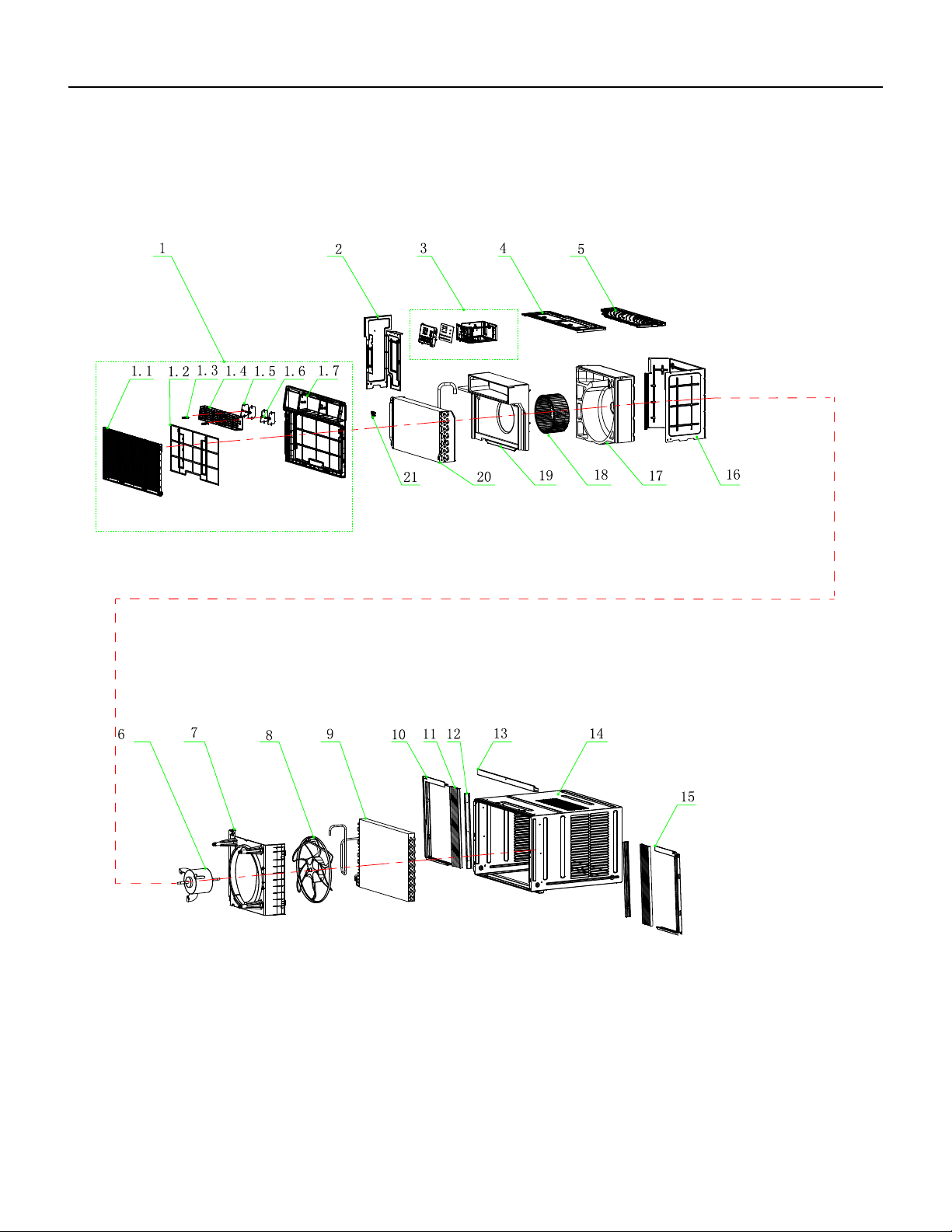
59 PB
PARTS CATALOG
Chill Premier Models: CCW24B30A
FIgure 903
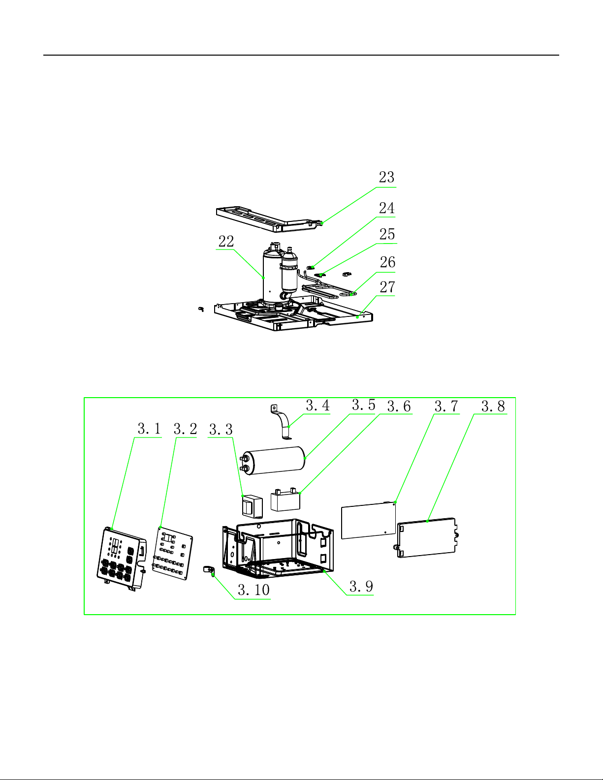
60 PB
PARTS CATALOG
Chill Premier Models: CCW24B30A
FIgure 903
61 PB
ITEM PART
NUMBER
PART DESCRIPTION USED ON MODEL QTY
1 68000332 41106-003519_UW - Front Panel
Assembly
CCW24B30A 1
1.2 68000334 41507-000137 - Air Filter CCW24B30A 1
2 68000339 41205-000164 - Left Supporter CCW24B30A 1
3 68000340 41505-000229 - Electrical Box
Assembly
CCW24B30A 1
3.1 68000341 41507-000033 - Control Box panel CCW24B30A 1
3.2 68000342 31502-000026 - Display PCB CCW24B30A 1
3.3 68000328 10502-100034_UW - Transformer CCW24B30A 1
3.4 68000189 42001-000027 - Capacitor Strip CCW24B30A 1
3.5 68000343 22003-000006_UW - Compressor
Capacitor
CCW24B30A 1
3.6 68000344 10303-100018_UW - Fan Motor
Capacitor
CCW24B30A 1
3.7 68000326 31502-000006_UW - Main pcb CCW24B30A 1
3.8 68000310 41214-000877_UW - Main pcb
supporter
CCW24B30A 1
3.9 68000345 41505-000232 - Electrical Box CCW24B30A 1
3.1 68000322 42001-000058 - Cable Clamp CCW24B30A 1
4 68000346 41504-000056 - Top Cover CCW24B30A 1
5 68000347 41504-000051 - Back Surround
Cover Plate
CCW24B30A 1
6 68000348 22001-000167_UW - Fan Motor CCW24B30A 1
7 68000349 41504-000045_UW - Back
Surround Plate
CCW24B30A 1
8 68000294 41503-000008_UW - Propeller
Fan
CCW24B30A 1
9 68000350 92011-000773 - Condenser CCW24B30A 1
10 68000351 41509-000046 - left Adjustable
shade rail
CCW24B30A 1
11 68000352 41509-000018 - Adjustable shade CCW24B30A 1
12 68000353 41214-000579 - Adjustable shade
rod
CCW24B30A 1
13 68000354 41509-000025 - Up Adjustable
shade rail
CCW24B30A 1
14 68000355 41508-000009_UW - Cabinet CCW24B30A 1
15 68000356 41509-000036 - Right Adjustable
shade rail
CCW24B30A 1
16 68000357 41504-000037 - Partition plate CCW24B30A 1
17 68000358 41504-000144_UW - Back Vortex
Shell
CCW24B30A 1
18 68000359 41503-000011_UW - Centrifugal
Fan
CCW24B30A 1
FIgure 903
PARTS CATALOG
Chill Premier Models: CCW24B30A
62 PB
PARTS CATALOG
Chill Premier Models: CCW24B30A
ITEM PART
NUMBER
PART DESCRIPTION USED ON MODEL QTY
19 68000360 41504-000150_UW - Front Vortex
Shell
CCW24B30A 1
20 68000361 92011-003350 - Evaporator CCW24B30A 1
21 68000305 41605-000011 - Sensor Holder CCW24B30A 1
22 68000362 92014-000276 - Compressor CCW24B30A 1
23 68000363 41504-000098 - Water drainage
pan
CCW24B30A 1
24 68000301 41214-000856 - Pipe Cover (two-
way)
CCW24B30A 1
25 68000300 41214-000857 - Pipe Cover (four-
way)
CCW24B30A 1
26 68000364 92007-003557 - cold tube CCW24B30A 1
27 68000365 41502-000004_UW - Base CCW24B30A 1
-28 68000331 22007-000067_UW - Power
Supply Cord
CCW24B30A 1
-29 68000314 22013-000936 - Remote
Controller
CCW24B30A 1
-30 68000232 10104-100026 - Sensor Assembly CCW24B30A 1
-35 68000237 32001-000129 - WIFI Assembly CCW24B30A 1
-ITEMS ARE NON- ILLUSTRATED
*ITEMS ARE NON-STOCKED, WILL NORMALLY REQUIRE 2-3 WEEKS LEAD TIME
FIgure 903
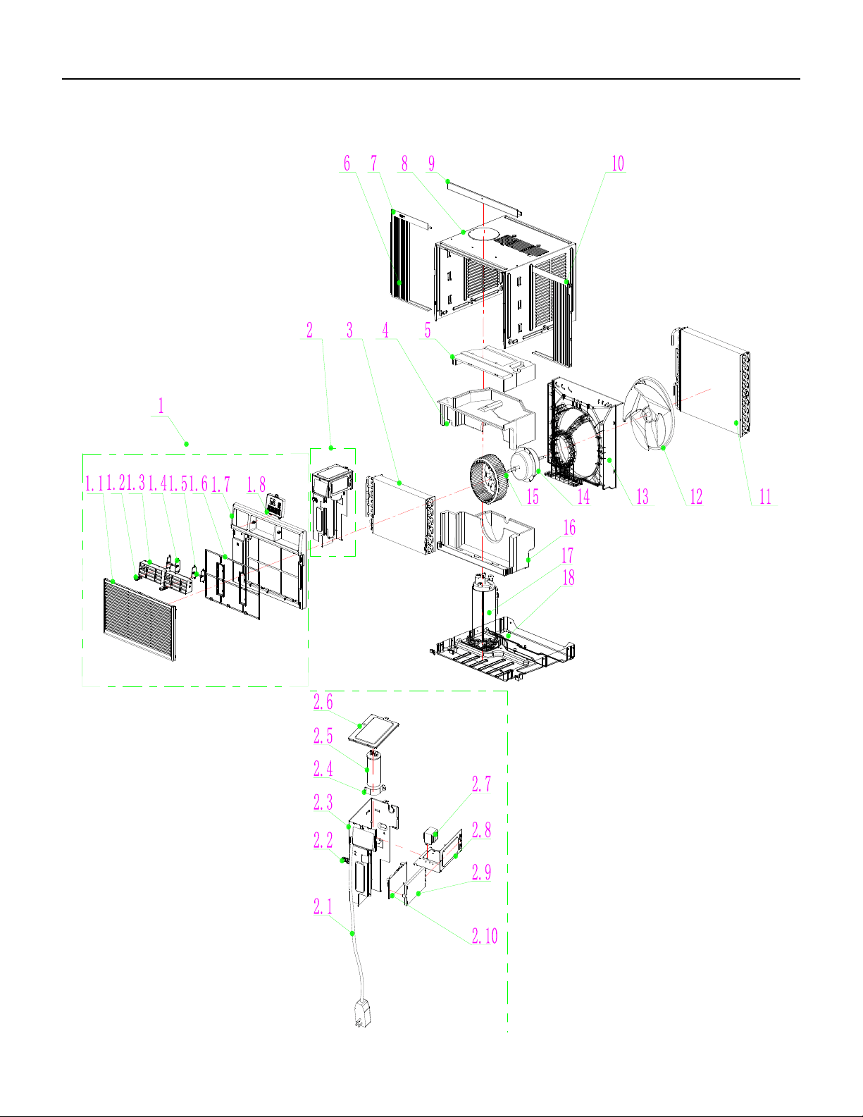
63 PB
FIgure 904
PARTS CATALOG
Chill Premier Models: CEW08B11A, CEW12B33A
64 PB
FIgure 904
ITEM PART
NUMBER
PART DESCRIPTION USED ON MODEL QTY
1 68000449 Front Panel Assembly ALL 1
1.1 68000165 Intake grille ALL 1
1.2 68000167 swing rod ALL 1
1.3 68000169 Leading Flow Circle ALL 1
1.4 68000171 Louver ALL 1
1.5 68000173 Louver Connecter ALL 1
1.6 68000175 Air Filter ALL 1
1.7 68000177 Front Panel ALL 1
1.8 68000179 Control Box panel ALL 1
2 68000181 Electrical Box Assembly ALL 1
2.1 68000256 Power Supply Cord CEW08B11A 1
2.1 68000331 Power Supply Cord CEW12B33A 1
2.2 68000257 Cable Clamp CEW08B11A 1
2.2 68000322 Cable Clamp CEW12B33A 1
2.3 68000187 Electrical Box ALL 1
2.4 68000189 Capacitor Strip ALL 1
2.5 68000193 Fan Capacitor CEW08B11A 1
2.5 68000457 Compressor Capacitor CEW12B33A 1
2.6 68000195 Electrical Box Cover ALL 1
2.7 68000197 Transformer CEW08B11A 1
2.7 68000328 Transformer CEW12B33A 1
2.8 #N/A Electrical Box base supporter CEW12B33A 1
2.9 68000201 Main pcb supporter ALL 1
2.10 68000450 Main pcb CEW08B11A 1
2.10 68000421 Main pcb CEW12B33A 1
3 68000245 Evaporator CEW08B11A 1
3 68000458 Evaporator CEW12B33A 1
4 68000451 Middle Vortex Shell ALL 1
5 68000452 Up Vortex Shell ALL 1
6 68000211 Adjustable shade ALL 1
7 68000221 left Adjustable shade rail ALL 1
8 68000222 Cabinet ALL 1
8 68000222 Cabinet ALL 1
9 68000223 Up Adjustable shade rail ALL 1
10 68000224 Right Adjustable shade rail ALL 1
11 68000205 Condenser CEW08B11A 1
11 68000260 Condenser CEW12B33A 1
12 68000225 Propeller Fan ALL 1
PARTS CATALOG
Chill Premier Models: CEW08B11A, CEW12B33A
65 PB
PARTS CATALOG
Chill Premier Models: CEW08B11A, CEW12B33A
FIgure 904
ITEM PART
NUMBER
PART DESCRIPTION USED ON MODEL QTY
13 68000250 Back Surround Plate ALL 1
14 68000227 Fan Motor CEW08B11A 1
14 68000459 Fan Motor CEW12B33A 1
15 68000453 Centrifugal Fan ALL 1
16 68000229 Water drainage pan ALL 1
17 68000254 Compressor CEW08B11A 1
17 68000460 Compressor CEW12B33A 1
18 68000454 Base ALL 1
19 68000232 Sensor ALL 1
20 68000315 Display PCB ALL 1
21 68000455 carton ALL 1
22 68000235 Base Carton Assembly ALL 1
23 68000236 Top cover ALL 1
24 68000237 WIFI Assembly ALL 1
25 68000422 Remote Controller ALL 1
26 68000456 Electric heating CEW08B11A 1
26 68000461 Electric heating CEW12B33A 1
-27 68000241 Compressor Capacitor CEW08B11A 1
-ITEMS ARE NON- ILLUSTRATED
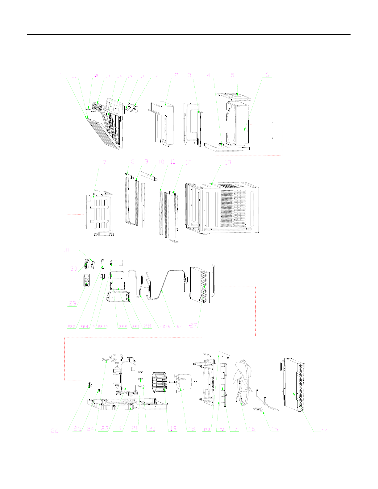
66 PB
FIgure 905
PARTS CATALOG
Chill Premier Models: CEW18B33A
67 PB
FIgure 905
ITEM PART
NUMBER
PART DESCRIPTION USED ON MODEL QTY
1 68000273 41106-003518 - Front Panel
Assembly
CEW18B1833A 1
1.1 68000274 41607-000080 - Intake grille CEW18B1833A 1
1.2 68000167 41507-000106 - swing rod CEW18B1833A 1
1.3 68000275 41507-000126 - Leading Flow
Circle
CEW18B1833A 1
1.4 68000276 42008-000095 - Air Filter CEW18B1833A 1
1.5 68000277 41607-000059 - Front Panel CEW18B1833A 1
1.6 68000278 41507-000072 - Louver Connecter CEW18B1833A 1
1.7 68000279 41507-000098 - Louver CEW18B1833A 1
2 68000415 41504-000088 - Front Vortex
Shell(UP)
CEW18B1833A 1
3 68000417 41214-001077 - Electrical Box
Cover supporter
CEW18B1833A 1
4 68000282 41504-000099 - Water drainage
pan
CEW18B1833A 1
5 68000283 41504-000055 - Top plate CEW18B1833A 1
6 68000418 41304-000072 - Back Vortex Shell CEW18B1833A 1
7 68000285 41504-000038 - Partition plate CEW18B1833A 1
8 68000286 41509-000040 - left Adjustable
shade rail
CEW18B1833A 1
9 68000287 41509-000014 - Adjustable shade CEW18B1833A 1
10 68000288 41509-000026 - Up Adjustable
shade rail
CEW18B1833A 1
11 68000289 41214-000913 - Adjustable shade
rod
CEW18B1833A 1
12 68000290 41509-000030 - Right Adjustable
shade rail
CEW18B1833A 1
13 68000291 41608-000012 - Cabinet CEW18B1833A 1
14 68000292 92011-000770 - Condenser CEW18B1833A 1
15 68000293 92007-003562 - cold tube CEW18B1833A 1
16 68000294 41503-000008 - Propeller Fan CEW18B1833A 1
17 68000295 41706-000002 - Back Surround
Plate Assembly
CEW18B1833A 1
17.1 68000296 41604-000010 - Back Surround
Plate
CEW18B1833A 1
17.2 68000297 41504-000049 - Back Surround
Cover Plate
CEW18B1833A 1
18 68000320 22001-000172 - Fan Motor CEW18B1833A 1
19 68000419 41503-000012 - Centrifugal Fan CEW18B1833A 1
20 68000300 41214-000857 - Pipe Cover (four-
way)
CEW18B1833A 1
PARTS CATALOG
Chill Premier Models: CEW18B33A

68 PB
PARTS CATALOG
Chill Premier Models: CEW18B33A
FIgure 905
ITEM PART
NUMBER
PART DESCRIPTION USED ON MODEL QTY
21 68000301 41214-000856 - Pipe Cover (two-
way)
CEW18B1833A 1
22 68000420 41602-000022 - Base CEW18B1833A 1
23 68000321 92014-000275 - Compressor CEW18B1833A 1
24 68000304 22007-000280 - Compressor wire CEW18B1833A 1
25 68000322 42001-000058 - Cable Clamp CEW18B1833A 1
26 68000305 41605-000011 - Sensor Holder CEW18B1833A 1
27 68000323 92011-003349 - Evaporator CEW18B1833A 1
27.1 68000324 92007-001525 - Capillary
Assembly
CEW18B1833A 1
27.2 68000325 92006-000180 - Discharge Pipe CEW18B1833A 1
28 68000309 41505-000233 - Electrical Box CEW18B1833A 1
28.1 68000201 41214-000877 - Main pcb
supporter
CEW18B1833A 1
28.2 68000421 31502-000010 - Main pcb CEW18B1833A 1
28.3 68000327 10303-100040 - Capacitor CEW18B1833A 1
28.4 68000328 10502-100034 - Transformer CEW18B1833A 1
28.5 68000329 42001-000025 - Capacitor Strip CEW18B1833A 1
29 68000422 22013-000789 - Remote
Controller
CEW18B1833A 1
30 68000179 41507-000031 - Control Box panel CEW18B1833A 1
31 68000315 31502-000027 - Display PCB CEW18B1833A 1
32 68000331 22007-000067 - Power Supply
Cord
CEW18B1833A 1
33 68000232 10104-100026 - Sensor Assembly CEW18B1833A 1
34 68000423 22004-000067 - Electrically
assisted heating
CEW18B1833A 1
38 68000237 32001-000129 - WIFI Assembly CEW18B1833A 1
39 68000425 12501-100001 - battery CEW18B1833A 1
40 68000426 41214-000499 - sponge (PU
1100X40X25)
CEW18B1833A 1
41 68000427 42006-000235 - sponge (PU
1050*50*3)
CEW18B1833A 1
42 68000428 41399-000023 - Insulating sponge CEW18B1833A 1
43 68000288 41509-000026 - Up Adjustable
shade rail
CEW18B1833A 1
44 68000429 41509-000006 - Adjustable shade
Assembly
CEW18B1833A 1
45 68000430 41214-000132 - sash lock CEW18B1833A 1
46 68000431 41214-000411 - Support plate CEW18B1833A 1
47 68000432 50803-100002 - bolt( M6×18) CEW18B1833A 1
48 68000433 50612-100010 - nut(M6) CEW18B1833A 1

69 PB
PARTS CATALOG
Chill Premier Models: CEW18B33A
FIgure 905
ITEM PART
NUMBER
PART DESCRIPTION USED ON MODEL QTY
49 68000434 50209-100009 - gasket(inner
diameterφ4.3×t1.0)
CEW18B1833A 1
50 68000435 51307-100006 - screw(ST4.2×12) CEW18B1833A 1
51 68000436 51314-100035 - screw(ST4.8×16-
F-H)
CEW18B1833A 1
52 68000437 50704-100001 - bolt(M5×13) CEW18B1833A 1
53 68000438 50610-100019 - screw(M5) CEW18B1833A 1
54 68000439 51307-100005 - screw(ST4.8×8) CEW18B1833A 1
-56 68000416 41504-000094 - Front Vortex
Shell(DOWN)
CEW18B1833A 1
-ITEMS ARE NON- ILLUSTRATED
*ITEMS ARE NON-STOCKED, WILL NORMALLY REQUIRE 2-3 WEEKS LEAD TIME
70 PB
FIgure 906
PARTS CATALOG
Chill Premier Models: CEW24B33A
71 PB
PARTS CATALOG
Chill Premier Models: CEW24B33A
FIgure 906
72 PB
FIgure 906
ITEM PART
NUMBER
PART DESCRIPTION USED ON MODEL QTY
1 68000441 41106-003887 - Front Panel
Assembly
CEW24B33A 1
1.1 68000333 41507-000055 - Intake grille CEW24B33A 1
1.2 68000334 41507-000137 - Air Filter CEW24B33A 1
1.3 68000167 41507-000106 - swing rod CEW24B33A 1
1.4 68000335 41507-000117 - Leading Flow
Circle
CEW24B33A 1
1.5 68000336 41507-000093 - Louver CEW24B33A 1
1.6 68000337 41507-000075 - Louver
Connecter
CEW24B33A 1
1.7 68000338 41507-000023 - Front Panel CEW24B33A 1
2 68000442 41504-000054 - Left Supporter CEW24B33A 1
3 68000340 41505-000229 - Electrical Box
Assembly
CEW24B33A 1
3.1 68000322 42001-000058 - Cable Clamp CEW24B33A 1
3.1 68000341 41507-000033 - Control Box
panel
CEW24B33A 1
3.2 68000342 31502-000026 - Display PCB CEW24B33A 1
3.3 68000328 10502-100034 - Transformer CEW24B33A 1
3.4 68000189 42001-000027 - Capacitor Strip CEW24B33A 1
3.5 68000343 22003-000006 - Compressor
Capacitor
CEW24B33A 1
3.6 68000344 10303-100018 - Fan Motor
Capacitor
CEW24B33A 1
3.7 68000421 31502-000010 - Main pcb CEW24B33A 1
3.8 68000201 41214-000877 - Main pcb
supporter
CEW24B33A 1
3.9 68000345 41505-000232 - Electrical Box CEW24B33A 1
4 68000346 41504-000056 - Top Cover CEW24B33A 1
5 68000347 41504-000051 - Back Surround
Cover Plate
CEW24B33A 1
6 68000348 22001-000167 - Fan Motor CEW24B33A 1
7 68000349 41504-000045 - Back Surround
Plate
CEW24B33A 1
8 68000294 41503-000008 - Propeller Fan CEW24B33A 1
9 68000350 92011-000773 - Condenser CEW24B33A 1
10 68000351 41509-000046 - left Adjustable
shade rail
CEW24B33A 1
11 68000352 41509-000018 - Adjustable shade CEW24B33A 1
12 68000353 41214-000579 - Adjustable shade
rod
CEW24B33A 1
13 68000354 41509-000025 - Up Adjustable
shade rail
CEW24B33A 1
14 68000355 41508-000009 - Cabinet CEW24B33A 1
PARTS CATALOG
Chill Premier Models: CEW24B33A
73 PB
ITEM PART
NUMBER
PART DESCRIPTION USED ON MODEL QTY
15 68000356 41509-000036 - Right Adjustable
shade rail
CEW24B33A 1
16 68000357 41504-000037 - Partition plate CEW24B33A 1
17 68000443 41304-000070 - Back Vortex Shell CEW24B33A 1
18 68000419 41503-000012 - Centrifugal Fan CEW24B33A 1
19 68000444 41504-000090 - Front Vortex
ShellφUPφ
CEW24B33A 1
20 68000361 92011-003350 - Evaporator CEW24B33A 1
21 68000305 41605-000011 - Sensor Holder CEW24B33A 1
22 68000362 92014-000276 - Compressor CEW24B33A 1
23 68000363 41504-000098 - Water drainage
pan
CEW24B33A 1
24 68000301 41214-000856 - Pipe Cover (two-
way)
CEW24B33A 1
25 68000300 41214-000857 - Pipe Cover (four-
way)
CEW24B33A 1
26 68000364 92007-003557 - cold tube CEW24B33A 1
27 68000446 41502-000015 - Base CEW24B33A 1
28 68000331 22007-000067 - Power Supply
Cord
CEW24B33A 1
29 68000423 22004-000067 - Electrically
assisted heating
CEW24B33A 1
30 68000237 32001-000129 - WIFI Assembly CEW24B33A 1
31 68000422 22013-000789 - Remote
Controller
CEW24B33A 1
32 68000232 10104-100026 - Sensor Assembly CEW24B33A 1
33 68000366 41110-000316 - Cover Forming CEW24B33A 1
34 68000219 A1202-000038 - Base Forming CEW24B33A 1
35 68000220 A2005-000537 - Base Carton CEW24B33A 1
36 68000425 12501-100001 - battery CEW24B33A 1
37 68000447 41509-000002 - Adjustable shade
Assembly
CEW24B33A 1
38 68000354 41509-000025 - Up Adjustable
shade rail
CEW24B33A 1
39 68000426 41214-000499 - sponge (PU
1100X40X25)
CEW24B33A 1
40 68000427 42006-000235 - sponge (PU
1050*50*3)
CEW24B33A 1
41 68000448 41399-000026 - Insulating
sponge
CEW24B33A 1
42 68000430 41214-000132 - sash lock CEW24B33A 1
43 68000431 41214-000411 - Support plate CEW24B33A 1
44 68000432 50803-100002 - bolt( M6×18) CEW24B33A 1
45 68000433 50612-100010 - nut(M6) CEW24B33A 1
46 68000434 50209-100009 - gasket(inner
diameterφ4.3×t1.0)
CEW24B33A 1
47 68000435 51307-100006 - screw(ST4.2×12) CEW24B33A 1
74 PB
ITEM PART
NUMBER
PART DESCRIPTION USED ON MODEL QTY
48 68000436 51314-100035 - screw(ST4.8×16-
F-H)
CEW24B33A 1
49 68000437 50704-100001 - bolt(M5×13) CEW24B33A 1
50 68000438 50610-100019 - screw(M5) CEW24B33A 1
51 68000439 51307-100005 - screw(ST4.8×8) CEW24B33A 1
52 68000440 211407853 - Packaging plastic
bags
CEW24B33A 1
-53 68000445 41504-000092 - Front Vortex Shell
(DOWN)
CEW24B33A 1
1-ITEMS ARE NON- ILLUSTRATED
*ITEMS ARE NON-STOCKED, WILL NORMALLY REQUIRE 2-3 WEEKS LEAD TIME
75 PB
FIgure 907
PARTS CATALOG
Chill Premier Models: CCF05A10A CCF06A10A CCF08A10A
76 PB
PARTS CATALOG
Chill Premier Models: CCF05A10A CCF06A10A CCF08A10A
FIgure 907
ITEM PART
NUMBER
PART DESCRIPTION USED ON MODEL QTY
1 68000216 210826698 - Base CCF05A10A, CCF06A10A 1
1A 68000145 210826701 - Base CCF08A10A 1
2 68000218 210755572 - Front Panel
Assembly
CCF05A10A, CCF06A10A, CCF08A10A 1
3 68000014 210736640A - Air Filter CCF05A10A, CCF06A10A, CCF08A10A 1
4 68000008 210755573 - Leading Flow Circle CCF05A10A, CCF06A10A, CCF08A10A 1
5 68000118 211241456 - Evaporator CCF05A10A, CCF06A10A 1
5A 68000146 211241581 - Evaporator CCF08A10A 1
6 68000119 214146283C - Electrical Assembly CCF05A10A, CCF06A10A 1
6A 68000147 214169039 - Electrical Assembly CCF08A10A 1
6.1 68000120 210736632 - Control Box panel CCF05A10A, CCF06A10A, CCF08A10A 1
6.2 68000029 210901461E - display pcb CCF05A10A, CCF06A10A, CCF08A10A 1
6.3 68000015 210901411N - Main pcb CCF05A10A, CCF06A10A, CCF08A10A 1
6.4 68000065 210736568 - Main pcb supporter CCF05A10A, CCF06A10A, CCF08A10A 1
6.5 68000040 210901721 - Transformer CCF05A10A, CCF06A10A, CCF08A10A 1
6.6 68000121 210826496 - Capacitor Strip CCF05A10A, CCF06A10A, CCF08A10A 1
6.7 68000009 210901420 - Capacitor CCF05A10A, CCF06A10A 1
6.7A 68000025 210901421 - Capacitor CCF08A10A 1
6.8 68000122 210826675 - Electrical Box Cover CCF05A10A, CCF06A10A 1
6.8A 68000148 210826680 - Electrical Box Cover CCF08A10A 1
7 68000010 210736634 - Centrifugal Fan CCF05A10A, CCF06A10A 1
7A 68000016 210736645 - Centrifugal Fan CCF08A10A 1
8 68000123 210736642A - Up Vortex Shell CCF05A10A, CCF06A10A 1
8A 68000150 210736646A - Up Vortex Shell CCF08A10A 1
9 68000124 210736643A - Middle Vortex Shell CCF05A10A, CCF06A10A 1
9A 68000151 210736647A - Middle Vortex Shell CCF08A10A 1
10 68000125 210736644A - Down Vortex Shell CCF05A10A, CCF06A10A 1
10A 68000152 210736648A - Down Vortex Shell CCF08A10A 1
11 68000053 210736635A - Back Partition plate CCF05A10A, CCF06A10A, CCF08A10A 1
12 68000126 211244320 - Discharge Pipe CCF05A10A 1
12a 68000143 211241569 - Discharge Pipe CCF06A10A 1
12B 68000153 211241653 - Discharge Pipe CCF08A10A 1
13 68000217 211233963 - Compressor CCF05A10A 1
13a 68000073 211234046 - Compressor CCF06A10A 1
13B 68000154 211234047 - Compressor CCF08A10A 1
14 68000011 210901425 - Fan Motor CCF05A10A, CCF06A10A 1
14A 68000017 210901424 - Fan Motor CCF08A10A 1
15 68000127 211233812 - Suction Pipe CCF05A10A, CCF06A10A 1
15A 68000155 211233801 - Suction Pipe CCF08A10A 1
77 PB
PARTS CATALOG
Chill Premier Models: CCF05A10A CCF06A10A CCF08A10A
FIgure 907
ITEM PART
NUMBER
PART DESCRIPTION USED ON MODEL QTY
16 68000018 210736633 - Propeller Fan CCF05A10A, CCF06A10A, CCF08A10A 1
17 68000128 211237530B - Condenser CCF05A10A 1
17a 68000144 211241574B - Condenser CCF06A10A 1
17B 68000156 211241577B - Condenser CCF08A10A 1
18 68000012 210826699 - Cabinet CCF05A10A, CCF06A10A 1
18A 68000019 210826702 - Cabinet CCF08A10A 1
22 68000036 210902158A - Remote Controller CCF05A10A, CCF06A10A, CCF08A10A 1
23 68000020 210901453 - Power Supply Cord CCF05A10A, CCF06A10A, CCF08A10A 1
24 68000021 210901454 - Sensor Assembly CCF05A10A, CCF06A10A, CCF08A10A 1
25 68000061 214169183 - installation
accessories
CCF05A10A, CCF06A10A, CCF08A10A 1
25.1 68000133 210737549 - Insulation strip
sponge
CCF05A10A, CCF06A10A, CCF08A10A 1
25.2 68000134 210737020 - Window Sash seal CCF05A10A, CCF06A10A, CCF08A10A 1
25.3 68000135 210737051 - Foam Top window
Gasket
CCF05A10A, CCF06A10A, CCF08A10A 1
25.4 68000022 210826772 - Top mounting Rail CCF05A10A, CCF06A10A, CCF08A10A 1
25.5 68000023 210755639 - Filler Panels CCF05A10A, CCF06A10A, CCF08A10A 1
25.6 68000023 210755640 - Filler Panels left Rail CCF05A10A, CCF06A10A, CCF08A10A 1
25.7 68000023 210755641 - Filler Panels right
Rail
CCF05A10A, CCF06A10A, CCF08A10A 1
25.8 68000023 211353335A - Filler Panels bag CCF05A10A, CCF06A10A, CCF08A10A 1
25.9 68000136 214146620 - Screw accessories CCF05A10A, CCF06A10A, CCF08A10A 1
25.9.1 68000137 1193070510 - Screw bag CCF05A10A, CCF06A10A, CCF08A10A 1
25.9.2 68000138 210826603 - Sash lock CCF05A10A, CCF06A10A, CCF08A10A 1
25.9.3 68000139 210826602 - Lock Frame CCF05A10A, CCF06A10A, CCF08A10A 1
25.9.4 68000140 1180010035 - screw 4.2*9.5 CCF05A10A, CCF06A10A, CCF08A10A 1
25.9.5 68000141 1180010019 - screw 4.2*13 CCF05A10A, CCF06A10A, CCF08A10A 1
25.9.6 68000142 1180010025 - screw 4.2*19 CCF05A10A, CCF06A10A, CCF08A10A 1
26 68000039 214154672 - Wi module CCF05A10A, CCF06A10A, CCF08A10A 1
-ITEMS ARE NON- ILLUSTRATED
*ITEMS ARE NON-STOCKED, WILL NORMALLY REQUIRE 2-3 WEEKS LEAD TIME
78 PB
FIgure 908
PARTS CATALOG
Chill Premier Models: CCF10A10A CCF12A10A
79 PB
PARTS CATALOG
Chill Premier Models: CCF10A10A CCF12A10A
FIgure 908
ITEM PART
NUMBER
PART DESCRIPTION USED ON MODEL QTY
1 68000160 214146537B - Front Panel
Assembly
CCF10A10A, CCF12A10A 1
1.1 68000024 210755514 - Intake grille CCF10A10A, CCF12A10A 1
1.2 68000027 210736617A - Air Filter CCF10A10A, CCF12A10A 1
2 68000161 214146589D - Electrical Assembly CCF10A10A, CCF12A10A 1
2.1 68000162 210736672 - Cable Clamp CCF10A10A, CCF12A10A 1
2.2 68000164 210826720 - Electrical Box
Assembly
CCF10A10A, CCF12A10A 1
2.3 68000121 210826496 - Capacitor Strip CCF10A10A, CCF12A10A 1
2.4 68000025 210901421 - Capacitor CCF10A10A 1
2.4A 68000028 210901423 - Capacitor CCF12A10A 1
2.5 68000166 210826683 - Electrical Box Cover CCF12A10A 1
2.6 68000029 210901461E - Display PCB CCF10A10A, CCF12A10A 1
2.7 68000168 210736561 - Control Box panel CCF10A10A, CCF12A10A 1
2.8 68000040 210901721 - Transformer CCF10A10A, CCF12A10A 1
2.9 68000030 210901411P - Main pcb CCF10A10A, CCF12A10A 1
2.10 68000031 210901539 - Sensor Assembly CCF10A10A, CCF12A10A 1
3 68000170 211234445 - Evaporator CCF10A10A 1
3A 68000200 211234361 - Evaporator CCF12A10A 1
4 68000172 210736652A - Middle Vortex Shell CCF10A10A, CCF12A10A 1
5 68000174 210736651A - Up Vortex Shell CCF10A10A, CCF12A10A 1
6 68000176 214146541 - Cabinet CCF10A10A, CCF12A10A 1
7 68000178 211234443B - Condenser CCF10A10A 1
7A 68000202 211234345B - Condenser CCF12A10A 1
8 68000032 210736728 - Propeller Fan CCF10A10A, CCF12A10A 1
9 68000180 210736621A - Back Surround
Plate
CCF10A10A, CCF12A10A 1
10 68000033 210901435 - Fan Motor CCF10A10A, CCF12A10A 1
11 68000034 210736727 - Centrifugal Fan CCF10A10A, CCF12A10A 1
12 68000182 210736653A - Down Vortex Shell CCF10A10A, CCF12A10A 1
13 68000184 211234297 - Compressor CCF10A10A 1
13A 68000204 211234298 - Compressor CCF12A10A 1
14 68000206 210736570 - Pipe Cover (two-way) CCF12A10A 1
15 68000208 211234354 - cold tube CCF12A10A 1
16 68000210 210736569 - Pipe Cover (four-way) CCF12A10A 1
17 68000186 210826728 - Base CCF10A10A, CCF12A10A 1
18 68000035 210901453A - Power Supply Cord CCF10A10A, CCF12A10A 1
19 68000188 211351575AU - carton CCF10A10A, CCF12A10A 1
20 68000190 211351574 - Base Carton CCF10A10A, CCF12A10A 1
21 68000192 211350337 - Base Foaming CCF10A10A, CCF12A10A 1
80 PB
PARTS CATALOG
Chill Premier Models: CCF10A10A CCF12A10A
FIgure 908
ITEM PART
NUMBER
PART DESCRIPTION USED ON MODEL QTY
22 68000194 211350338 - Top cover CCF10A10A, CCF12A10A 1
23 68000036 210902158A - Remote Controller CCF10A10A, CCF12A10A 1
24 68000196 210755642 - installation
accessories
CCF10A10A, CCF12A10A 1
24.1 68000198 210737550 - Insulation strip
sponge
CCF10A10A, CCF12A10A 1
24.2 68000134 210737020 - Window Sash seal CCF10A10A, CCF12A10A 1
24.3 68000135 210737051 - Foam Top window
Gasket
CCF10A10A, CCF12A10A 1
24.4 68000212 210755644 - Filler Panels CCF10A10A, CCF12A10A 1
24.5 68000213 210755645 - Filler Panels Left
Rail
CCF10A10A, CCF12A10A 1
24.6 68000214 210755646 - Filler Panels Right
Rail
CCF10A10A, CCF12A10A 1
24.7 68000215 211354038A - Filler Panels bag CCF10A10A, CCF12A10A 1
24.8 68000136 214146620 - Screw accessories CCF10A10A, CCF12A10A 1
24.8.1 68000137 1193070510 - Screw bag CCF10A10A, CCF12A10A 1
24.8.2 68000138 210826603 - Sash lock CCF10A10A, CCF12A10A 1
24.8.3 68000139 210826602 - Lock Frame CCF10A10A, CCF12A10A 1
24.8.4 68000140 1180010035 - screw 4.2*9.5 CCF10A10A, CCF12A10A 1
24.8.5 68000141 1180010019 - screw 4.2*13 CCF10A10A, CCF12A10A 1
24.8.6 68000142 1180010025 - screw 4.2*19 CCF10A10A, CCF12A10A 1
25 68000038 210826820 - Top mounting Rail CCF10A10A, CCF12A10A 1
26 68000039 214154672 - Wi module CCF10A10A, CCF12A10A 1
-ITEMS ARE NON- ILLUSTRATED
*ITEMS ARE NON-STOCKED, WILL NORMALLY REQUIRE 2-3 WEEKS LEAD TIME
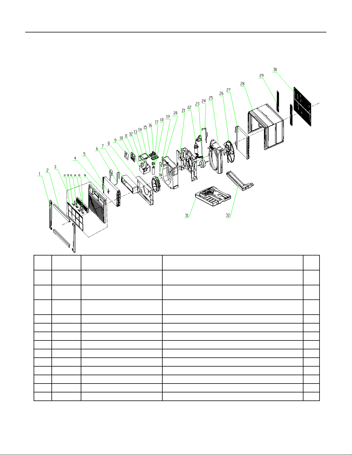
81 PB
PARTS CATALOG
Unit Models: UCT08A10A UCT10A10A UCT12A10A UCT10A30A
FIgure 909
ITEM PART
NUMBER
PART DESCRIPTION USED ON MODEL QTY
1 68000055 210738331 - Display decorative
piece1
UCT08A10A, UCT10A10A, UCT12A10A, UCT10A30A 1
2 68000056 210738332 - Display decorative
piece2
UCT08A10A, UCT10A10A, UCT12A10A, UCT10A30A 1
3 68000057 210755503 - Front Panel
Assembly
UCT08A10A, UCT10A10A, UCT12A10A, UCT10A30A 1
3.1 68000058 210755506 - Air Filter UCT08A10A, UCT10A10A, UCT12A10A, UCT10A30A 1
4 68000373 211244404 - Evaporator UCT08A10A, 1
4A 68000391 211238697 - Evaporator UCT10A10A, UCT10A30A 1
4B 68000398 211238079 - Evaporator UCT12A10A 1
5 #N/A #N/A UCT08A10A, UCT10A10A, UCT12A10A, UCT10A30A 1
6 68000374 211244403 - Capillary Assembly UCT08A10A 1
6A 68000392 211238698 - Capillary Assembly UCT10A10A, UCT10A30A 1
6B 68000399 211238080 - Capillary Assembly UCT12A10A 1
7 68000375 210738268A - Outlet foam UCT08A10A, UCT10A10A, UCT12A10A, UCT10A30A 1
8 68000376 210836747 - Front Partition plate UCT08A10A, UCT10A10A, UCT12A10A, UCT10A30A 1
82 PB
ITEM PART
NUMBER
PART DESCRIPTION USED ON MODEL QTY
9 68000377 210755615A - Display PCB cover UCT08A10A, UCT10A10A, UCT12A10A, UCT10A30A 1
10 68000132 210738277 - Control Box panel UCT08A10A, UCT10A10A, UCT12A10A, UCT10A30A 1
11 68000378 210836910 - Electrical Box UCT08A10A, UCT10A10A, UCT12A10A, UCT10A30A 1
12 68000040 210901721 - Transformer UCT08A10A, UCT10A10A, UCT12A10A 1
12A 68000062 210901700 - Transformer UCT10A30A 1
13 68000041 210901745 - Fan Motor Capacitor UCT08A10A, UCT10A10A, UCT12A10A, UCT10A30A 1
14 68000379 210836752 - Electrical Box Cover UCT08A10A, UCT10A10A, UCT12A10A, UCT10A30A 1
15 68000030 210901411P - Main pcb UCT08A10A, UCT10A10A, UCT12A10A, UCT10A30A 1
16 68000065 210736568 - Main pcb supporter UCT08A10A, UCT10A10A, UCT12A10A, UCT10A30A 1
17 68000380 210738282 - Capacitor Strip UCT08A10A, UCT10A10A, UCT12A10A, UCT10A30A 1
18 68000043 1170100033A - Compressor
Capacitor
UCT08A10A 1
18A 68000000 1170100007C - Compressor
Capacitor
UCT10A10A 1
18B 68000047 1170100023A - Compressor
Capacitor
UCT10A30A 1
18C 68000001 210901831 - Compressor
Capacitor
UCT12A10A 1
19 68000006 210738336 - Centrifugal Fan UCT08A10A, UCT10A10A, UCT12A10A, UCT10A30A 1
20 68000381 210738267A - foam shell UCT08A10A, UCT10A10A, UCT12A10A, UCT10A30A 1
21 68000382 210836909A - Partition plate UCT08A10A, UCT10A10A, UCT12A10A, UCT10A30A 1
22 68000383 211237425 - Compressor UCT08A10A 1
22A 68000393 211236834 - Compressor UCT10A10A 1
22B 68000396 211231767 - Compressor UCT10A30A 1
22C 68000400 211238084 - Compressor UCT12A10A 1
23 68000044 210901757 - Fan Motor UCT08A10A, UCT10A10A 1
23A 68000068 210901723 - Fan Motor UCT10A30A 1
23B 68000002 210901722 - Fan Motor UCT12A10A 1
24 68000384 211237435 - Discharge Pipe UCT08A10A 1
24A 68000394 211238696 - Discharge Pipe UCT10A10A 1
24B 68000394 211238696 - Discharge Pipe UCT10A30A 1
24C 68000401 211236902 - Discharge Pipe UCT12A10A 1
25 68000069 210738266A - Back Partition plate UCT08A10A, UCT10A10A, UCT12A10A, UCT10A30A 1
26 68000070 210738337 - Propeller Fan UCT08A10A, UCT10A10A, UCT12A10A, UCT10A30A 1
27 68000385 211236831B - Condenser UCT08A10A, UCT10A10A, UCT12A10A, UCT10A30A 1
27A 68000402 211236922B - Condenser UCT12A10A 1
28 68000071 210836745 - Cabinet UCT08A10A, UCT10A10A, UCT12A10A, UCT10A30A 1
29 68000072 210836793 - grille UCT08A10A, UCT10A10A, UCT12A10A, UCT10A30A 1
PARTS CATALOG
Unit Models: UCT08A10A UCT10A10A UCT12A10A UCT10A30A
FIgure 909
83 PB
PARTS CATALOG
Unit Models: UCT08A10A UCT10A10A UCT12A10A UCT10A30A
FIgure 909
ITEM PART
NUMBER
PART DESCRIPTION USED ON MODEL QTY
30 68000048 210836767 - intake and outtake
grille
UCT08A10A, UCT10A10A, UCT12A10A, UCT10A30A 1
31 68000386 210836781A - Base UCT08A10A, UCT10A10A, UCT12A10A, UCT10A30A 1
32 68000051 210738265 - Water drainage pan UCT08A10A, UCT10A10A, UCT12A10A, UCT10A30A 1
-34 68000035 210901453A - Power Supply Cord UCT08A10A, UCT10A10A, UCT12A10A 1
-34A 68000397 210901453E - Power Supply Cord UCT10A30A 1
-35 68000036 210902158A - Remote Controller UCT08A10A, UCT10A10A, UCT12A10A, UCT10A30A 1
-36 68000054 210901730A - Display PCB UCT08A10A, UCT10A10A, UCT12A10A, UCT10A30A 1
-ITEMS ARE NON- ILLUSTRATED
*ITEMS ARE NON-STOCKED, WILL NORMALLY REQUIRE 2-3 WEEKS LEAD TIME
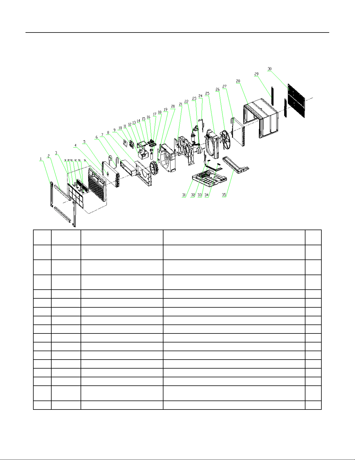
84 PB
FIgure 910
ITEM PART
NUMBER
PART DESCRIPTION USED ON MODEL QTY
1 68000055 210738331 - Display decorative
piece1
UCT12A30A, UCT14A30A 1
2 68000056 210738332 - Display decorative
piece2
UCT12A30A, UCT14A30A 1
3 68000057 210755503 - Front Panel
Assembly
UCT12A30A, UCT14A30A 1
3.1 68000058 210755506 - Air Filter UCT12A30A, UCT14A30A 1
4 68000398 211238079 - Evaporator UCT12A30A 1
4A 68000407 211244409 - Evaporator UCT14A30A 1
6 68000399 211238080 - Capillary Assembly UCT12A30A 1
6A 68000408 211244408 - Capillary Assembly UCT14A30A 1
7 68000375 210738268A - Outlet foam UCT12A30A, UCT14A30A 1
8 68000376 210836747 - Front Partition plate UCT12A30A, UCT14A30A 1
9 68000377 210755615A - Display PCB cover UCT12A30A, UCT14A30A 1
10 68000132 210738277 - Control Box panel UCT12A30A, UCT14A30A 1
11 68000378 210836910 - Electrical Box UCT12A30A, UCT14A30A 1
12 68000062 210901700 - Transformer UCT12A30A, UCT14A30A 1
13 68000063 1170100034A - Fan Motor
Capacitor
UCT12A30A, UCT14A30A 1
14 68000379 210836752 - Electrical Box Cover UCT12A30A, UCT14A30A 1
PARTS CATALOG
Unit Models: UCT12A30, UCT14A30A
85 PB
ITEM PART
NUMBER
PART DESCRIPTION USED ON MODEL QTY
15 68000395 210901411H - Main pcb UCT12A30A, UCT14A30A
16 68000065 210736568 - Main pcb supporter UCT12A30A, UCT14A30A 1
17 68000380 210738282 - Capacitor Strip UCT12A30A, UCT14A30A 1
18 68000066 1170100004A - Compressor
Capacitor
UCT12A30A 1
18A 68000074 1170100026A - Compressor
Capacitor
UCT14A30A 1
19 68000006 210738336 - Centrifugal Fan UCT12A30A, UCT14A30A 1
20 68000381 210738267A - foam shell UCT12A30A, UCT14A30A 1
21 68000382 210836909A - Partition plate UCT12A30A, UCT14A30A 1
22 68000403 211238076 - Compressor UCT12A30A 1
22A 68000409 211236912 - Compressor UCT14A30A 1
23 68000068 210901723 - Fan Motor UCT12A30A, UCT14A30A 1
24 68000401 211236902 - Discharge Pipe UCT12A30A, UCT14A30A 1
25 68000069 210738266A - Back Partition plate UCT12A30A, UCT14A30A 1
26 68000070 210738337 - Propeller Fan UCT12A30A, UCT14A30A 1
27 68000402 211236922B - Condenser UCT12A30A, UCT14A30A 1
28 68000071 210836745 - Cabinet UCT12A30A, UCT14A30A 1
29 68000072 210836793 - grille UCT12A30A, UCT14A30A 1
30 68000048 210836767 - intake and outtake
grille
UCT12A30A, UCT14A30A 1
31 68000386 210836781A - Base UCT12A30A, UCT14A30A 1
32 68000404 211236909 - cold tube UCT12A30A 1
33 68000405 210738333 - Pipe Cover (two-way) UCT12A30A, UCT14A30A 1
34 68000406 210738334 - Pipe Cover (three-
way)
UCT12A30A, UCT14A30A 1
35 68000051 210738265 - Water drainage pan UCT12A30A, UCT14A30A 1
-36 68000036 210902158A - Remote Controller UCT12A30A, UCT14A30A 1
-37 68000397 210901453E - Power Supply Cord UCT12A30A, UCT14A30A 1
-39 68000054 210901730A - Display PCB UCT12A30A, UCT14A30A 1
-ITEMS ARE NON- ILLUSTRATED
*ITEMS ARE NON-STOCKED, WILL NORMALLY REQUIRE 2-3 WEEKS LEAD TIME
PARTS CATALOG
Unit Models: UCT12A30A, UCT14A30A
FIgure 910
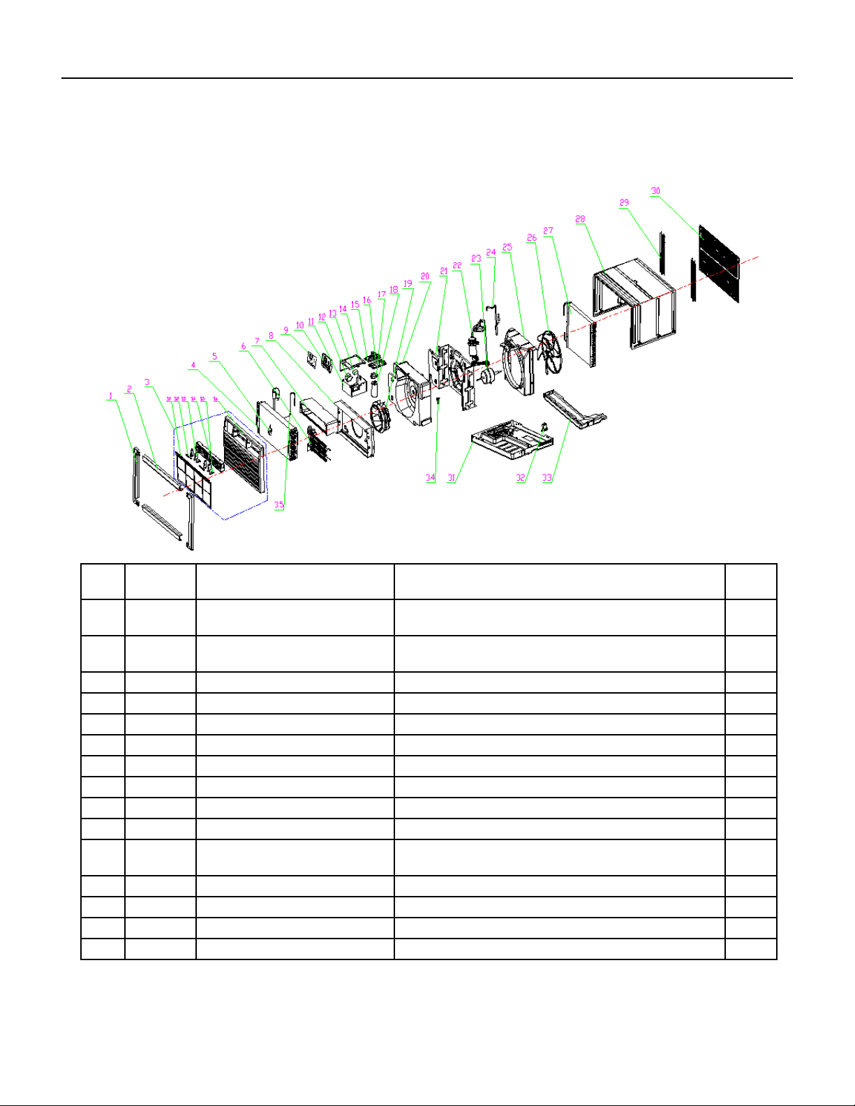
86 PB
1 68000055 210738331 - Display decorative
piece1
UET08A11A, UET10A33A, UET12A33A 1
2 68000056 210738332 - Display decorative
piece2
UET08A11A, UET10A33A, UET12A33A 1
3 68000057 210755503 - Front Panel
Assembly
UET08A11A, UET10A33A, UET12A33A 1
3.1 68000058 210755506 - Air Filter UET08A11A, UET10A33A, UET12A33A 1
4 68000373 211244404 - Evaporator UET08A11A 1
4A 68000391 211238697 - Evaporator UET10A33A 1
4B 68000398 211238079 - Evaporator UET12A33A 1
5 #N/A #N/A UET08A11A, UET10A33A, UET12A33A 1
6 68000410 210901744 - Heater UET08A11A 1
6A 68000059 210901743 - Heater UET10A33A, UET12A33A 1
7 68000375 210738268A - Outlet foam UET08A11A, UET10A33A, UET12A33A 1
8 68000060 210755614A - Front Partition
plate
UET08A11A 1
8A 68000376 210836747 - Front Partition plate UET10A33A, UET12A33A 1
9 68000060 210755614A - Display PCB cover UET08A11A, UET10A33A, UET12A33A 1
10 68000132 210738277 - Control Box panel UET08A11A, UET10A33A, UET12A33A 1
11 68000378 210836910 - Electrical Box UET08A11A, UET10A33A, UET12A33A 1
PARTS CATALOG
Unit Models: UET08A11A UET10A33A UET12A33A
FIgure 911
87 PB
PARTS CATALOG
Unit Models: UET08A11A UET10A33A UET12A33A
12 68000040 210901721 - Transformer UET08A11A 1
12A 68000062 210901700 - Transformer UET10A33A, UET12A33A 1
13 68000041 210901745 - Fan Motor Capacitor UET08A11A 1
13A 68000046 1170100030A - Fan Motor
Capacitor
UET10A33A 1
13B 68000063 1170100034A - Fan Motor
Capacitor
UET12A33A 1
14 68000379 210836752 - Electrical Box Cover UET08A11A, UET10A33A, UET12A33A 1
15 68000042 210901411S - Main pcb UET08A11A 1
15A 68000064 210901411R - Main pcb UET10A33A, UET12A33A 1
16 68000065 210736568 - Main pcb supporter UET08A11A, UET10A33A, UET12A33A 1
17 68000380 210738282 - Capacitor Strip UET08A11A, UET10A33A, UET12A33A 1
18 68000043 1170100033A - Compressor
Capacitor
UET08A11A 1
18A 68000047 1170100023A - Compressor
Capacitor
UET10A33A 1
18B 68000066 1170100004A - Compressor
Capacitor
UET12A33A 1
19 68000067 210738381 - Centrifugal Fan UET08A11A, UET10A33A, UET12A33A 1
20 68000411 210738267 - foam shell UET08A11A, UET10A33A, UET12A33A 1
21 68000382 210836909A - Partition plate UET08A11A, UET10A33A, UET12A33A 1
22 68000383 211237425 - Compressor UET08A11A 1
22A 68000396 211231767 - Compressor UET10A33A 1
22B 68000403 211238076 - Compressor UET12A33A 1
23 68000044 210901757 - Fan Motor UET08A11A 1
23A 68000068 210901723 - Fan Motor UET10A33A, UET12A33A 1
24 68000384 211237435 - Discharge Pipe UET08A11A 1
24A 68000394 211238696 - Discharge Pipe UET10A33A 1
24B 68000401 211236902 - Discharge Pipe UET12A33A 1
25 68000069 210738266A - Back Partition plate UET08A11A, UET10A33A, UET12A33A 1
26 68000070 210738337 - Propeller Fan UET08A11A, UET10A33A, UET12A33A 1
27 68000385 211236831B - Condenser UET08A11A, UET10A33A 1
27A 68000402 211236922B - Condenser UET12A33A 1
28 68000071 210836745 - Cabinet UET08A11A, UET10A33A, UET12A33A 1
29 68000072 210836793 - grille UET08A11A, UET10A33A, UET12A33A 1
30 68000048 210836767 - intake and outtake
grille
UET08A11A, UET10A33A, UET12A33A 1
31 68000412 210836781 - Base UET08A11A, UET10A33A, UET12A33A 1
32 68000050 210901012 - Drainage valve UET08A11A, UET10A33A, UET12A33A 1
33 68000051 210738265 - Water drainage pan UET08A11A, UET10A33A, UET12A33A 1
FIgure 911
88 PB
PARTS CATALOG
Unit Models: UET08A11A UET10A33A UET12A33A
-34 68000413 210738117 - Sensor supporter
(outlet)
UET08A11A, UET10A33A, UET12A33A 1
-35 68000374 211244403 - Capillary Assembly UET08A11A 1
-35A 68000392 211238698 - Capillary Assembly UET10A33A 1
-35B 68000399 211238080 - Capillary Assembly UET12A33A 1
-37 68000045 210901453D - Power Supply Cord UET08A11A 1
-37A 68000052 210901453B - Power Supply Cord UET10A33A, UET12A33A 1
-38 68000036 210902158A - Remote Controller UET08A11A, UET10A33A, UET12A33A 1
-39 68000054 210901730A - Display PCB UET08A11A, UET10A33A, UET12A33A 1
-ITEMS ARE NON- ILLUSTRATED
*ITEMS ARE NON-STOCKED, WILL NORMALLY REQUIRE 2-3 WEEKS LEAD TIME
FIgure 911
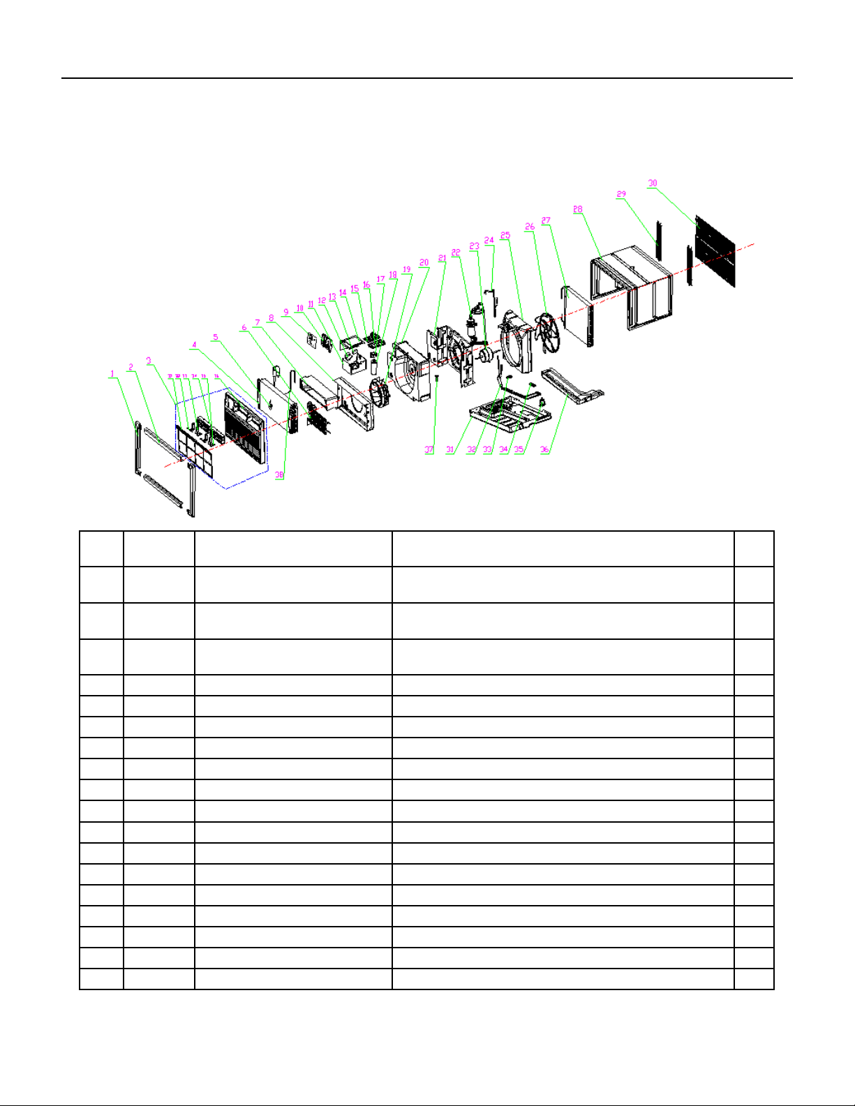
89 PB
PARTS CATALOG
Unit Models: UET14A33A
FIgure 912
ITEM PART
NUMBER
PART DESCRIPTION USED ON MODEL QTY
1 68000055 210738331 - Display decorative
piece1
UET14A33A 1
2 68000056 210738332 - Display decorative
piece2
UET14A33A 1
3 68000057 210755503 - Front Panel
Assembly
UET14A33A 1
3.1 68000058 210755506 - Air Filter UET14A33A 1
4 68000407 211244409 - Evaporator UET14A33A 1
5 #N/A #N/A UET14A33A 1
6 68000059 210901743 - Heater UET14A33A 1
7 68000375 210738268A - Outlet foam UET14A33A 1
8 68000376 210836747 - Front Partition plate UET14A33A 1
9 68000060 210755614A - Display PCB cover UET14A33A 1
10 68000132 210738277 - Control Box panel UET14A33A 1
11 68000378 210836910 - Electrical Box UET14A33A 1
12 68000062 210901700 - Transformer UET14A33A 1
13 68000062 210901700 - Fan Motor Capacitor UET14A33A 1
14 68000379 210836752 - Electrical Box Cover UET14A33A 1
15 68000064 210901411R - Main pcb UET14A33A 1
16 68000065 210736568 - Main pcb supporter UET14A33A 1
17 68000380 210738282 - Capacitor Strip UET14A33A 1
90 PB
PARTS CATALOG
Unit Models: UET14A33A
FIgure 912
ITEM PART
NUMBER
PART DESCRIPTION USED ON MODEL QTY
18 68000074 1170100026A - Compressor
Capacitor
UET14A33A 1
19 68000067 210738381 - Centrifugal Fan UET14A33A 1
20 68000411 210738267 - foam shell UET14A33A 1
21 68000382 210836909A - Partition plate UET14A33A 1
22 68000409 211236912 - Compressor UET14A33A 1
23 68000068 210901723 - Fan Motor UET14A33A 1
24 68000401 211236902 - Discharge Pipe UET14A33A 1
25 68000069 210738266A - Back Partition plate UET14A33A 1
26 68000070 210738337 - Propeller Fan UET14A33A 1
27 68000402 211236922B - Condenser UET14A33A 1
28 68000071 210836745 - Cabinet UET14A33A 1
29 68000072 210836793 - grille UET14A33A 1
30 68000048 210836767 - intake and outtake
grille
UET14A33A 1
31 68000412 210836781 - Base UET14A33A 1
32 68000404 211236909 - cold tube UET14A33A 1
33 68000405 210738333 - Pipe Cover (two-way) UET14A33A 1
34 68000406 210738334 - Pipe Cover (three-
way)
UET14A33A 1
35 68000050 210901012 - Drainage valve UET14A33A 1
36 68000051 210738265 - Water drainage pan UET14A33A 1
37 68000413 210738117 - Sensor supporter
(outlet)
UET14A33A 1
38 68000408 211244408 - Capillary Assembly UET14A33A 1
-40 68000052 210901453B - Power Supply Cord UET14A33A 1
-41 68000036 210902158A - Remote Controller UET14A33A 1
-42 68000054 210901730A - Display PCB UET14A33A 1
-ITEMS ARE NON- ILLUSTRATED
*ITEMS ARE NON-STOCKED, WILL NORMALLY REQUIRE 2-3 WEEKS LEAD TIME
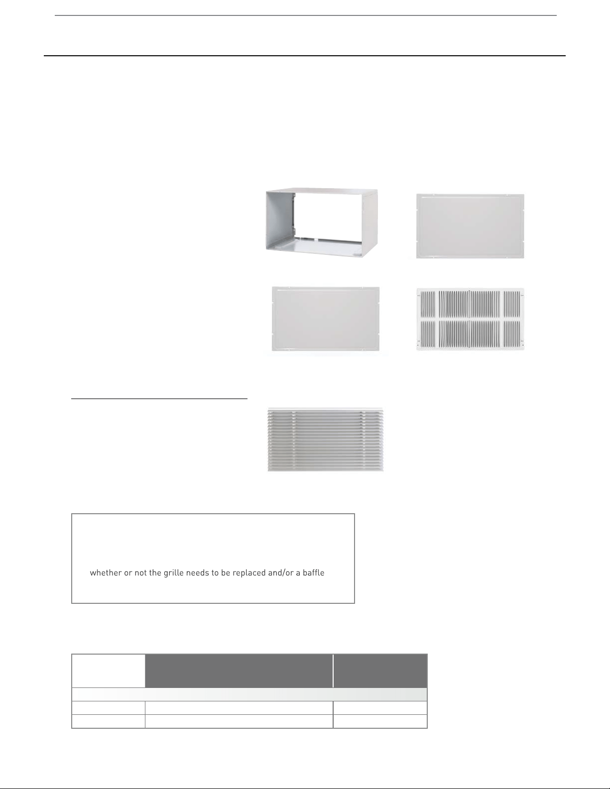
91 PB
Available Accessories
Unit
WSE SLEEVE/ EXTERIOR GRILLES
Model
DepthHeight Width
Depth
with
Front
Minimum
Extension
Into Room
Minimum
Extension
Outside
Thru-the-wall
Finished Hole
Uni-Fit
®
Height Width Max. Depth
USC Sleeve –
1
/
2
"15
1
/
2
" 25
7
/
8
" 16
3
/
4
" 20
1
/
2
" 15
3
/
4
" 26
1
/
8
" 16
1
/
4
"
UCT, UET Chassis
14
1
/
2
"
24
1
/
4
" -
20
5
/
16
"
– – – –
3
3
/
4
"
SLEEVE/ CHASSIS DIMENSIONS
USC SLEEVE
An existing or new sleeve is required for installation. The Friedrich USC sleeve ships with the accessories needed for installation in new
construction, or installation into an existing sleeve.
INCLUDED WITH USC SLEEVE
USC wall sleeve ships with weather
panels (2) and grille. Sleeve is shown
at right with:
IMPORTANT:
When installing into an existing sleeve, consult Installation
Section of your Installation/Operation Manual to determine
adapter (included with chassis) should be used.
Inner weather panelUSC sleeve
Outer weather panel
Standard grille
1. Painted steel inner panel
2. Painted steel outer panel
3. Painted steel standard grille
OPTIONAL GRILLE
ARCHITECTURAL GRILLE-UXAA
Optional extruded brushed aluminum grille.
UXAA, optional architectural grille

92 PB
Friedrich Air Conditioning Company
10001 Reunion Place, Suite 500
San Antonio, TX 78216
800-541-6645
www.friedrich.com
ROOM AIR CONDITIONERS
LIMITED WARRANTY
FIRST YEAR
ANY PART: If any part supplied by FRIEDRICH fails because of a defect in workmanship or material within twelve months from
date of original purchase, FRIEDRICH will repair the product at no charge, provided room air conditioner is reasonably accessible
for service. Any additional labor cost for removing inaccessible units and/or charges for mileage related to travel by a Service
Agency that exceeds 25 miles one way will be the responsibility of the owner. This remedy is expressly agreed to be the exclusive
remedy within twelve months from the date of the original purchase.
SECOND THROUGH FIFTH YEAR
SEALED REFRIGERANT SYSTEM: If the Sealed Refrigeration System (dened for this purpose as the compressor, condenser coil, evaporator
coil, reversing valve, check valve, capillary, lter drier, and all interconnecting tubing) supplied by FRIEDRICH in your Room Air Conditioner
fails because of a defect in workmanship or material within sixty months from date of purchase, FRIEDRICH will pay a labor allowance
of $100 and parts necessary to repair the Sealed Refrigeration System; PROVIDED FRIEDRICH will not pay any additional labor charges
over the prescribed labor allowance including the cost of diagnosis of the problem, removal, freight charges, and transportation of the air
conditioner to and from the Service Agency, and the reinstallation charges associated with repair of the Sealed Refrigeration System. All
such cost will be the sole responsibility of the owner. This remedy is expressly agreed to be the exclusive remedy within sixty months from
the date of the original purchase.
APPLICABILITY AND LIMITATIONS: This warranty is applicable only to units retained within the Fifty States of the U.S.A., District of
Columbia, and Canada. This warranty is not applicable to:
1. Air lters, fuses, batteries and the front grille removal tool.
2. Products on which the model and serial numbers have been removed.
3. Products which have defects or damage which results from improper installation, wiring, electrical current characteristics, or
maintenance; or caused by accident, misuse or abuse, re, ood, alterations and/or misapplication of the product and/or units
installed in a corrosive atmosphere, default or delay in performance caused by war, government restrictions or restraints, strikes,
material shortages beyond the control of FRIEDRICH, or acts of God.
OBTAINING WARRANTY PERFORMANCE: Service will be provided by the FRIEDRICH Authorized Dealer or Service Organization in your area. They
are listed in the Yellow Pages. If assistance is required in obtaining warranty performance, write to: Room Air Conditioner Service Manager (the
Friedrich address is at the top of this w arranty) or email [email protected].
LIMITATIONS: THIS WARRANTY IS GIVEN IN LIEU OF ALL OTHER WARRANTIES. Anything in the warranty notwithstanding, ANY IMPLIED
WARRANTIES OF FITNESS FOR PARTICULAR PURPOSE AND/OR MERCHANTABILITY SHALL BE LIMITED TO THE DURATION OF THIS
EXPRESS WARRANTY. MANUFACTURER EXPRESSLY DISCLAIMS AND EXCLUDES ANY LIABILITY FOR CONSEQUENTIAL OR INCIDENTAL
DAMAGE FOR BREACH OF ANY EXPRESSED OR IMPLIED WARRANTY.
Performance of Friedrich’s Warranty obligation is limited to one of the following methods:
1. Repair of the unit
2. A refund to the customer for the prorated value of the unit based upon the remaining w arranty period of the unit.
3. Providing a replacement unit of equal value
The method of fulllment of the warranty obligation is at the sole discretion of Friedrich Air Conditioning.
NOTE: Some states do not allow limitations on how long an implied w arranty lasts, or do not allow the limitation or exclusion of
consequential or incidental damages, so the foregoing exclusions and limitations may not apply to you.
OTHER: This warranty gives you specic legal rights, and you may also have other rights which vary from state to state.
PROOF OF PURCHASE: Owner must provide proof of purchase in order to receive any w arranty related services.
All service calls for explaining the operation of this product w ill be the sole responsibility of the consumer.
All warranty service must be provided by an Authorized FRIEDRICH Service Agency, unless authorized by FRIEDRICH prior to repairs being made.

93 PB
THIS PAGE LEFT INTENTIONALLY BLANK.

94 PB
Friedrich Air Conditioning Co.
10001 Reunion Place, Suite 500 • San Antonio, Texas 78216
1-800-541-6645
www.friedrich.com
TECHNICAL SUPPORT
CONTACT INFORMATION
CUSTOMER SATISFACTION and QUALITY ASSURANCE
Friedrich is a conscientious manufacturer, concerned about customer satisfaction, product quality, and controlling
warranty costs. As an Authorized Service Provider you play a vital role in these areas. By adhering to the policies
and procedures you provide us with vital information on each warranty repair you complete. This information
is used to identify product failure trends, initiate corrective action, and improve product quality, thereby further
reducing warranty expenses while increasing customer satisfaction levels.
FRIEDRICH AUTHORIZED PARTS DEPOTS
AAA Refrigeration Service
1322 24th Street, Suite B Kenner,
Louisiana 70062 504-464-7444
877-813-7444
Alamo Service Company
1450 North Flores Street San
Antonio, Texas 78212 210-227-
2450
800-328-2450
The Gabbert Company
6868 Ardmore
Houston, Texas 77054
713-747-4110
800-458-4110
Johnstone Supply of Woodside
27-01 Brooklyn Queens Expway
Woodside, New York 11377 718-
545-5464
800-431-1143
Reeve Air Conditioning, Inc.
2501 South Park Road Hallandale, Florida
33009 954-962-0252
800-962-3383