Installation and Operation Manual
THE EXPERTS IN ROOM AIR CONDITIONING
115 VOLT CCV15
230 VOLT CCV18, CCV24
Chassis Models
93011012_01

Table of Contents
Other Features
...............................................................................................................................
19
IMPORTANT SAFETY INSTRUCTIONS
....................................................
1
What’s in the Box
...............................................................................................................................
4
Introduction 5
Operating Instructions
............................................................................................................................
6
8Setup & Installation
...............................................................................................................................
18
Maintenance
..............................................................................................................................
20
...............................................................................................................................
Trouble shooting
..............................................................................................................................
1
IMPORTANT SAFETY INSTRUCTIONS
Before installing and using your air conditioner, please read this owner’s manual carefully. Store
this manual in a safe place for future reference.
Your safety and the safety of others is very important to us. Please pay attention to all safety
messages outlined in this owner’s manual.
WARNING: To reduce the risk of fire, electrical shock or injury when using your air conditioner,
follow the following basic precautions:
ELECTRICAL REQUIREMENTS
The electrical ratings for your air conditioner are listed on the model and serial number label
located on the front right hand side of theunit (when facing the front).
REGISTER YOUR APPLIANCE
You can register your appliance online by going to register.tcl.com
Be sure to retain your original sales receipt. A valid proof of purchase is required for all warranty
claims.
BATTERY WARNING STATEMENT
Do not mix old and new batteries and do not mix alkaline, standard (carbon-zinc) or rechargeable
(ni-cad, ni-mh, etc.) batteries
RECOMMENDED GROUND METHOD
For your personal safety, this air conditioner must be grounded. This air conditioner is equipped
with a 3 prong power supply cord with a grounded plug. To minimize the possibility of electrical
shock, the cord must be plugged into a 3 prong outlet and grounded in accordance with all local
codes and ordinances. If a 3 prong outlet is not available,it is the customer’s responsibility to
have a properly grounded 3 prong outlet installed by a qualified electrician.
contact us first
with any questions
WE ARE
REA DY TO
HELP
BE CA REF L HE R
EMOVING
THE A IR CO DITIONING UNIT
Document your model and serial numbers here:
Model #__________________________ Serial #________________________________
You can locate your 20 digit serial number underneath the bar code (On the right hand side
of the AC).
Electrical Shock Hazard
Plug into a grounded 3 prong outlet.
Do not remove the ground prong.
Do not use an adapter
Do not use an extension cord.
Failure to follow these instructions
can resultin death, fire, or electrical
shock
• 115V(103min-127max)
• (15K) (0-15 amps)
• (15K) (15 amp time-delay fuse or circuit breaker)
• 208/230V(187min-253max)
• (18K) (0-13 amps)
• (24K) (0-20 amps)
• (18K) (15 amp time-delay fuse or circuit breaker)
• (24K) (20 amp time-delay fuse or circuit breaker)
• Use on single outlet circuit only
Wiring Requirements Power Supply Cord
WARNING
Specific electrical requirements are shown in the
diagram below.Follow there quirements below for the
type of plug on the power supply cord.
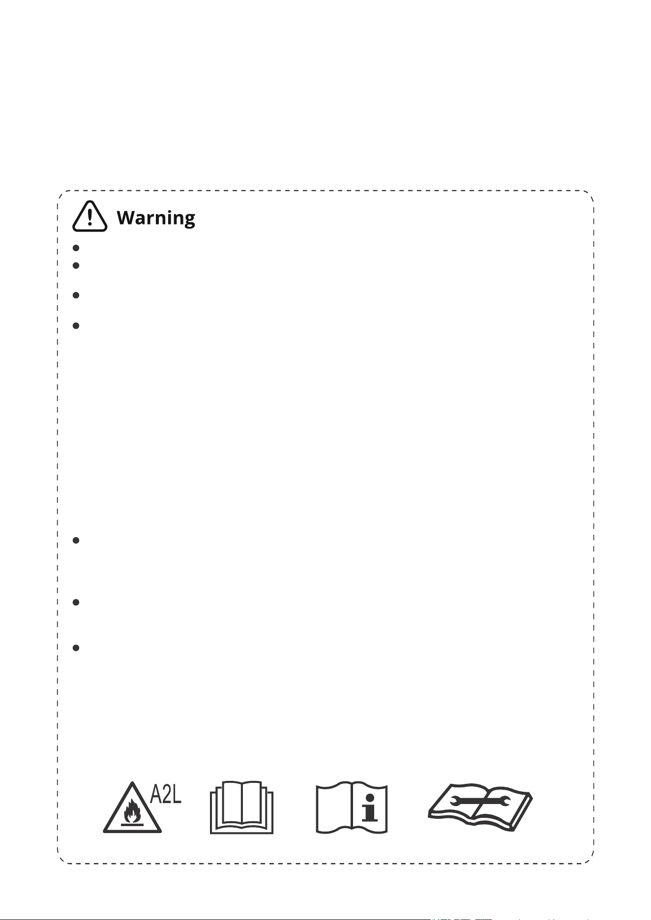
Do not use means to accelerate the defrosting process or to clean, other than those
recommended by the manufacturer;
The appliance shall be stored in a room without continuously operating ignition sources
(for example: open flames, an operating gas appliance or an operating electric heater.
Do not pierce or burn.
• Be aware that refrigerants may not contain an odour.
• information for handling, installation, cleaning, servicing and disposal of refrigerant.
• a warning to keep any required ventilation openings clear of obstruction.
• a notice that servicing shall be performed only as recommended by the manufacturer.
• Information for qualification of workers
• Information on servicing
• Repairs to sealed components
• Repairs to Intrinsically safe components
• Cabling
• Detection of flammable refrigerants
• Removal and evacuation
• Charging procedures
• Decommissioning, labelling and recovery
Please contact the nearest after-sale service center when maintenance is necessary.
At the time of maintenance, the maintenance personnel must strictly comply with the
Operation Manual provided by the corresponding manufacturer and any non-
professional is prohibited to maintain the air conditioner.
The handling, installation, storage, servicing and disposal must comply with the ]
provisions of gas-related national laws and regulations, and also national wiring
regulation.
It is necessary to clear away the refrigerant in the system when maintaining or
scrapping an air conditioner. Be aware that refrigerants may not contain an odour.
This appliance is not intended for use by persons (including children) with reduced
physical, sensory or mental capabilitiesor supervision or instruction concerning use of
the appliance by a person responsible for their safety.
Children should be supervised to ensure that they do not play with the appliance.
Unit operation limits: Outdoor side 61~110, 80%RH, indoor side 61~90, 80%RH.
2
Introduction to Refrigerants R32
Please read the manual before installation,using,maintenance.
The refrigerants used for air conditioners are environmentally friendly hydrocarbons R32.
This kind of erant is combustible and odorless. Moreover, it can burn and explode under certain
condition. However, there will be no risk of burning and explosion if you comply with the following
table to install your air conditioner in a room with an appropriate area and use it correctly.
Compared with ordinary refrigerants, Refrigerant R32 is environmentally friendly and do not
destroy the ozone sphere and that itsvalue of greenhouse effect is also very low.
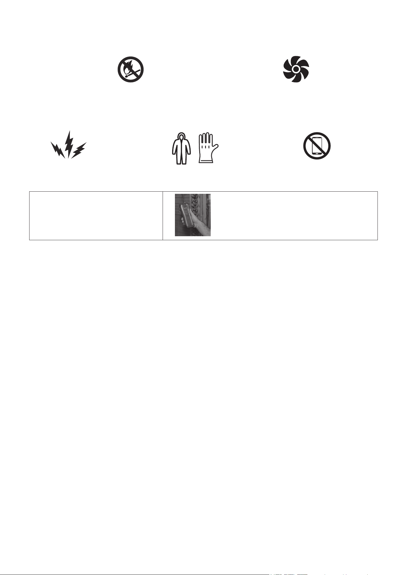
Installation Safety Principles
1. Site Safety
Open Flames Prohibited
Ventilation Necessary
2. Operation Safety
Open Flames Prohibited
Must wear protective clothing and
anti-static gloves
3. Installation Safety
• Refrigerant Leak Detector
• Appropriate Installation Location
The left picture is the schematic diagram
of a refrigerant leak detector.
Please note that:
1. The installation site should be in a well-ventilated area.
2. When installing an air conditioner, it is necessary to take appropriate anti-static measures such
as wear anti-static clothing and/or gloves.
3. Installation or maintenance location should not be surrounded by obstacles or close to any
heat source, flammable, and/or explosive areas or objects.
4. If the product suers refrigerant leak during the installation, all personnel should go out till the
refrigerant leaks completely for 15 minutes.If the product is damaged, a professional must carry
such damages product back to the maintenance station. It is prohibited to weld therefrigerant pipe
or conduct other operations on the contaminated site.
5. The air conditioner unit needs to sit on a flat even surface.
6. It is necessary to avoid the places where there are other electrical products, power switch
plugs and sockets, kitchen cabinet, bed, sofa and other valuables directly under the lines on two
sides of the indoor unit.
7. Any ventilation openings of unit should be free from obstructions.
Mind Static Electricity Don`t use mobile phone
3
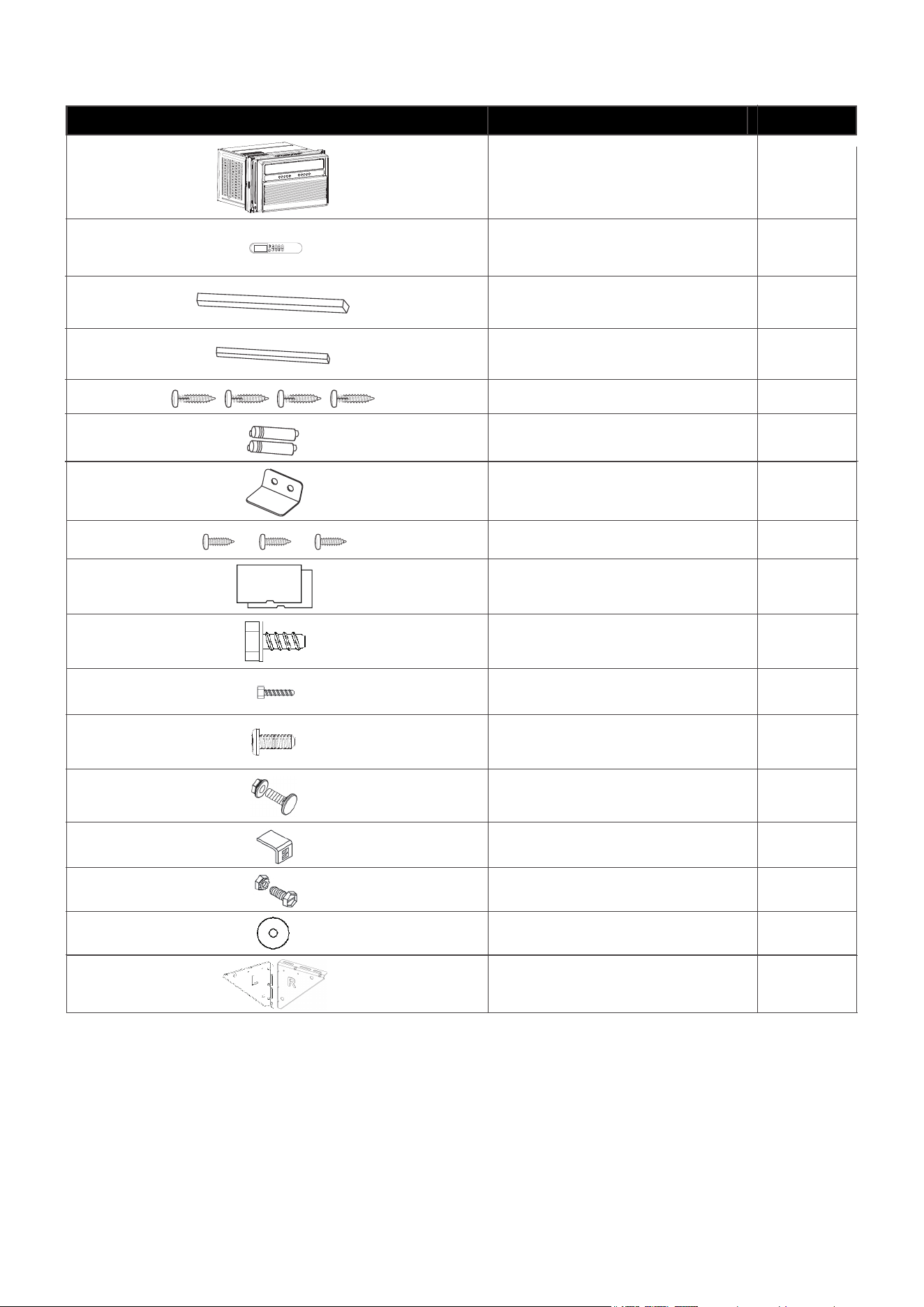
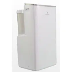
What’s in the Box
Open the carton and remove the below parts.
Note: Illustrations in this manual are for explanatory purposes only. Product design and
aesthetics may vary. Please search the entire package for the contents listed above as they
may be packaged on top or underneath the main AC unit.
4
APPEARANCE PART NAME QUANTITY
1
1
1
1
4
2
1
3
2
7
2
Window Air Conditioner
Remote Control
Long Foam Seal
(Non-Adhesive)
Long Foam Seal
(Adhesive)
¾” Screw
Remote Control Battery
Security Bracket
½” Screw
⁵⁄16” Long Hex-head Screw
¹⁄2” Long Hex-head Screw
2
2
4
2
2
Sill Angel Bracket
Gasket
Support Bracket
(with Rand L remark)
⁵⁄8” Long Flat head Bolt
and Locknut
¹⁄2” Long Flat head Bolt
and Locknut
Panel Seal
(Adhesive)
¹⁄4” Long Hex-head Screw
4
Introduction
For remote control model
Attention
1) The outlooking and some function of
remote control may vary according
to the model.
2) The shape and position of buttons and
indicators may vary according to the
model, but their function is the same.
3) The unit confirms the correct reception
of each press button with a beep.
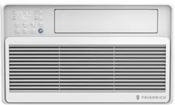
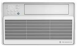
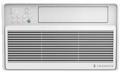
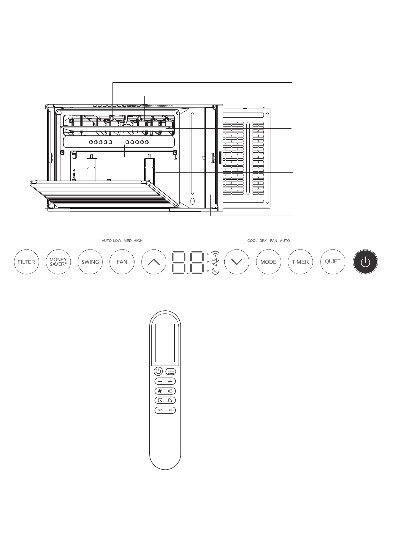
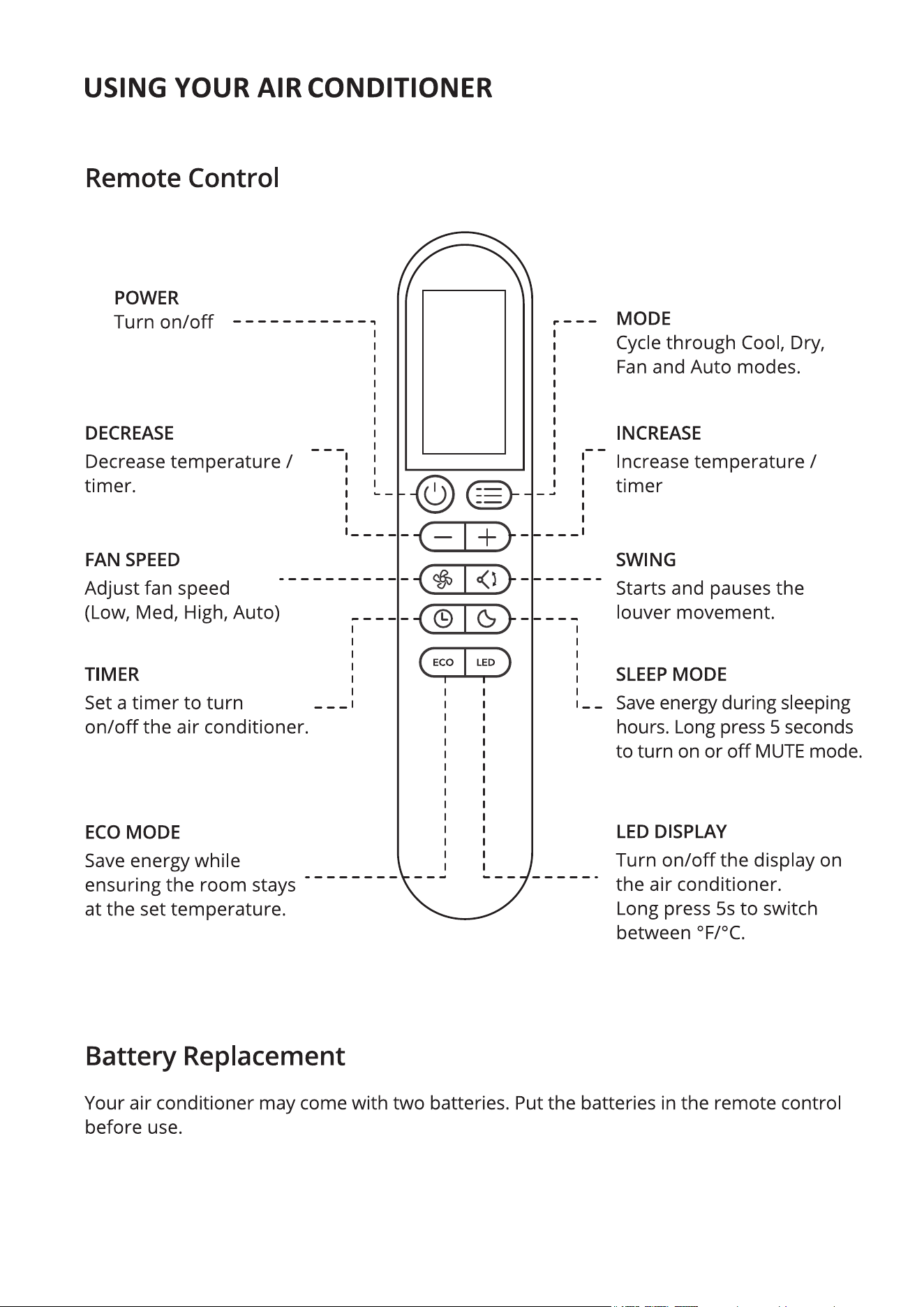
Remote Controller
Control Panel
5
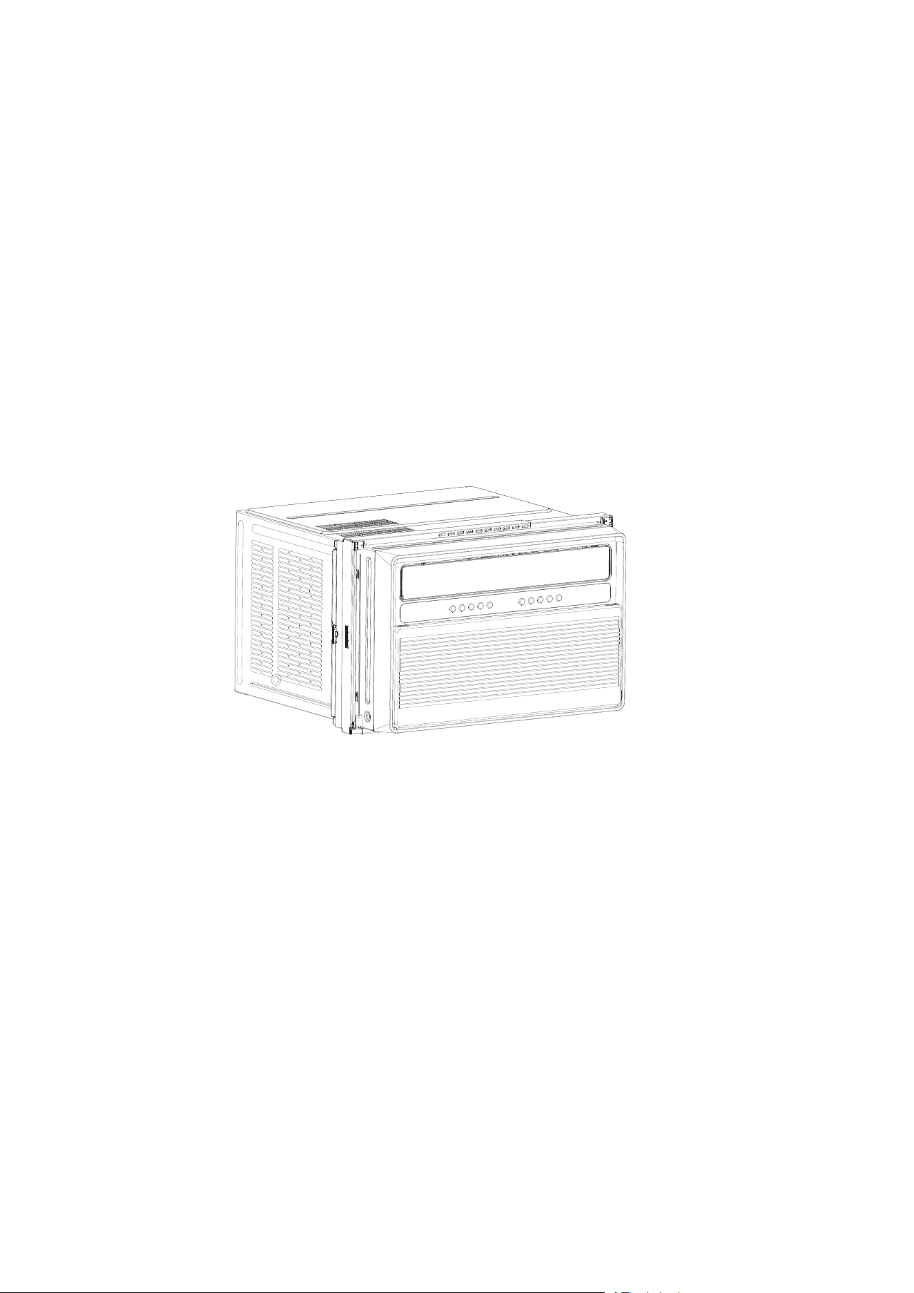
Front Panel
Air Louver
Grid Guard
Vane
Display Board
Air Filter
Telescopic Curtain Assy
Operating Instructions
For remote control model
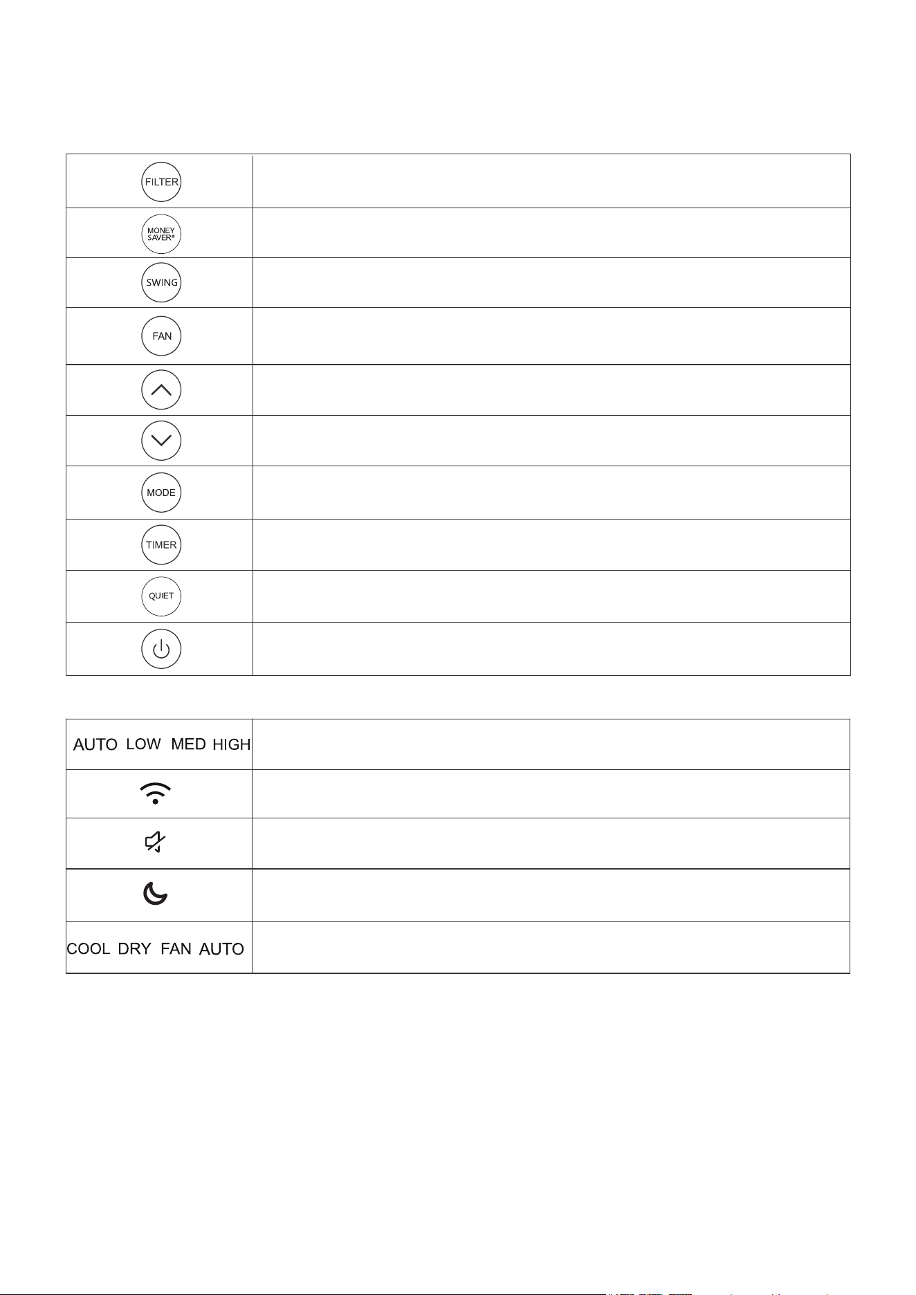
You can easily operate this air conditioner by press relevant button on the control panel as well
as the remote controller.
Clean the dust filter.
Adjust fan speed (Auto,Low, Med, High)
NOTE: Fan speed setting is available in Auto,Cool, and Fan modes only.
Turn on/off the MONEY SAVER mode, under Cool/Dry mode
Select to adjust the airflow direction by swinging the louver vertically.
Increase the air conditioning temperature.
Decrease the air conditioning temperature.
Switch between Cool/Dry/Fan/Auto mode.
Turn on/off the QUIET mode.
Timer on or Timer off the unit.
Turn on the air conditioner or switch to standby.
Indication symbols of LED on control panel
Indicates Automatic,Low,Medium and High fan speeds, respectively.
Indicates that there is a WiFi connection.
Indicates the unit is in MUTE mode.
Indicates the unit is in Sleep mode.
Indicates Cool, Dry, Fan, and Auto mode, respectively.
Description:
1) Above LED lights on when the relevant mode is in used.
2) In Eco mode, when the desired temperature is reached, the compressor will turn off and the
fan will continue to run for 3 minutes before turning off. The fan will turn on for 1-minute at every
5-minute interval until the room temperature is above the set temperature, at which time the
compressor turns back on and continues cooling.
3) When the running time reaches 500 hours, the filter reminder will light up to indicate the filter
needs to be cleaned. Press the Filter button to reset the filter reminder. Please see the
maintenance section of this manual for filter cleaning instructions.
6
7
8
Setup & Installation
Window Requirements
1. This air conditioner is designed to be installed in a standard single-hung or double-hungwindow
with a window width between 29.5” and 41” (750mm - 1040mm).
2. The lower sash (the lower part of the window that moves up and down) must allow for 14.5”of
vertical clearance when open.
4. All supporting parts must be secured to firm wood, masonry, or metal.
5. The electrical outlet must be within reach of the power cord. (Electrical outlets only, no power
strips or other outlets allowed.)
Note: Store the air conditioner in its product box while not in use.
Carefully remove all packaging and wraps from the air conditioner and its accessories.
Before installing your AC, let’s test it to make sure it works properly, and your outlet has the
proper power level.
First, place it on a flat surface, plug it directly into a wall outlet (never use a powerstrip or other
device), and turn it on.
Next, use the Mode button on your control panel to change the AC to Cool Mode and press the
down arrow to set the temperature to the lowest setting. After 3 minutes, the AC should be blowing
cool air. If so, please continue to the next step. If not, see detailed troubleshooting tips at support.
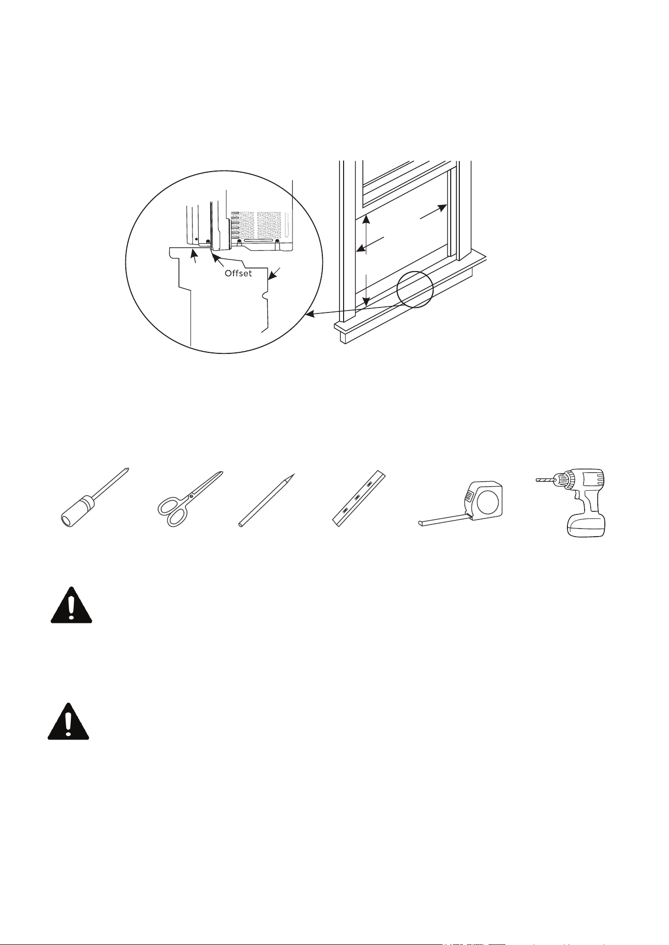
Suggested Tools for Installation (Not Included)
Phillips
Screwdriver
Scissors
or Knife
Pencil Level Tape Measurer
or Ruler
Drill and
1/8”Drill Bit
CAUTION
Heavy object. Team handling is required during the installation process.
29.5-41 inch
750-1040 mm
18.5 inch
470 mm
Exterior
Wall
Stool
Sill
Interior
Wall
Getting Started
Step 1: Unboxing
Step 2: Testing
CAUTION
Heavy object. Team handling is required during the installation process.
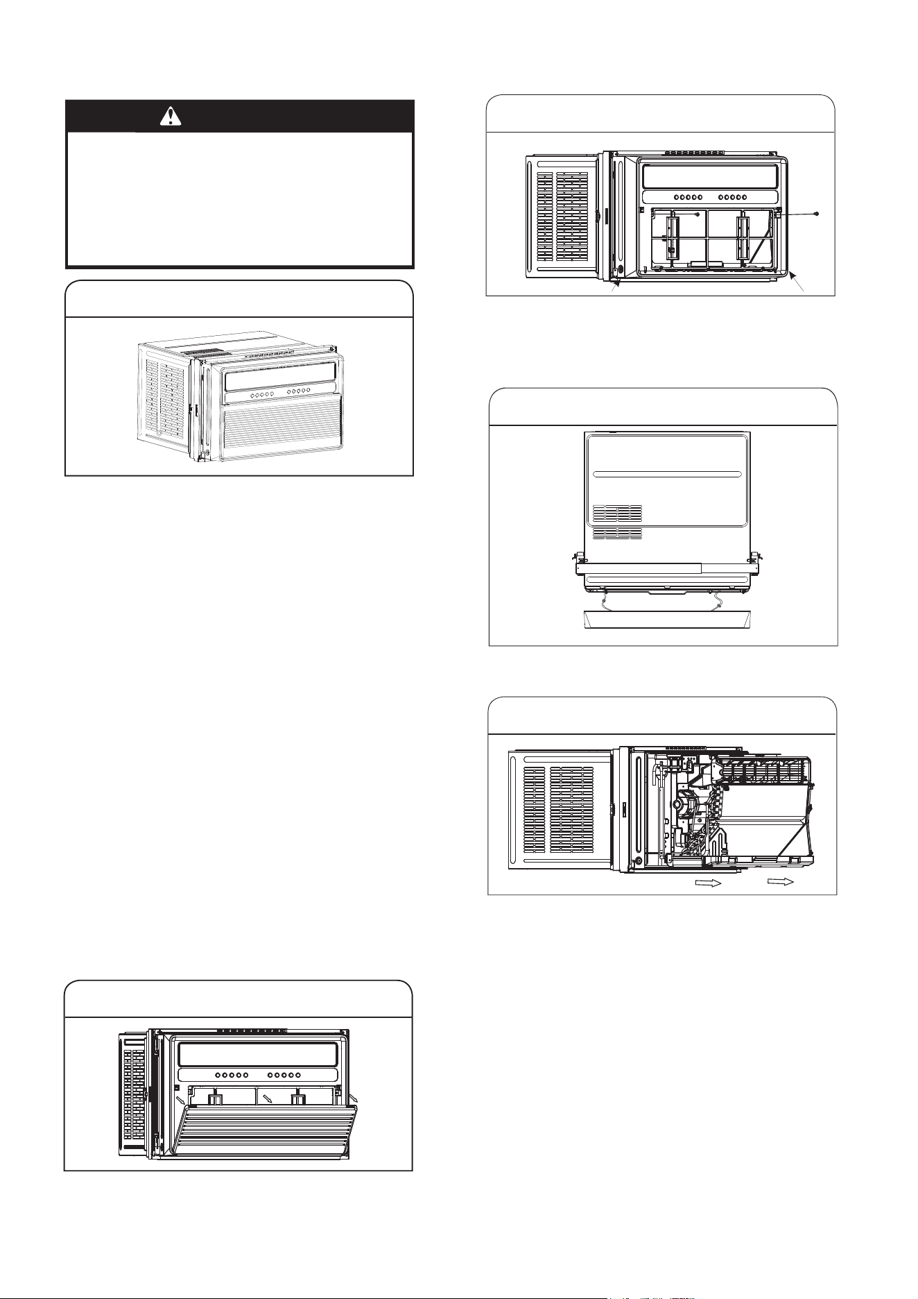
Prepare Air Conditioner for Installation
WARNING
Excessive Weight Hazard
Use two or more people to move and
installair conditioner.
Failure to do so can result in back or
other injury.
1.Unpack the Air Conditioner
Remove Packaging Materials:
Gently handle the air conditioner while
unpacking the unit.
Place the air conditioner on a hard, flat
surface.
Remove tape and glue residue from
surfaces before turning on the air
conditioner. Rub a small amount of liquid
dish soapover the adhesive with the
fingers. Wipe with a damp cloth and dry.
Do not use sharp instruments, rubbing
alcohol, flammable fluids, or abrasive
cleaners to remove tape or glue. These
products can damage the surface of the
air conditioner.
Remove any packaging materials inserted
into the side louvers.
Dispose of/recycle packaging materials in
an appropriate way.
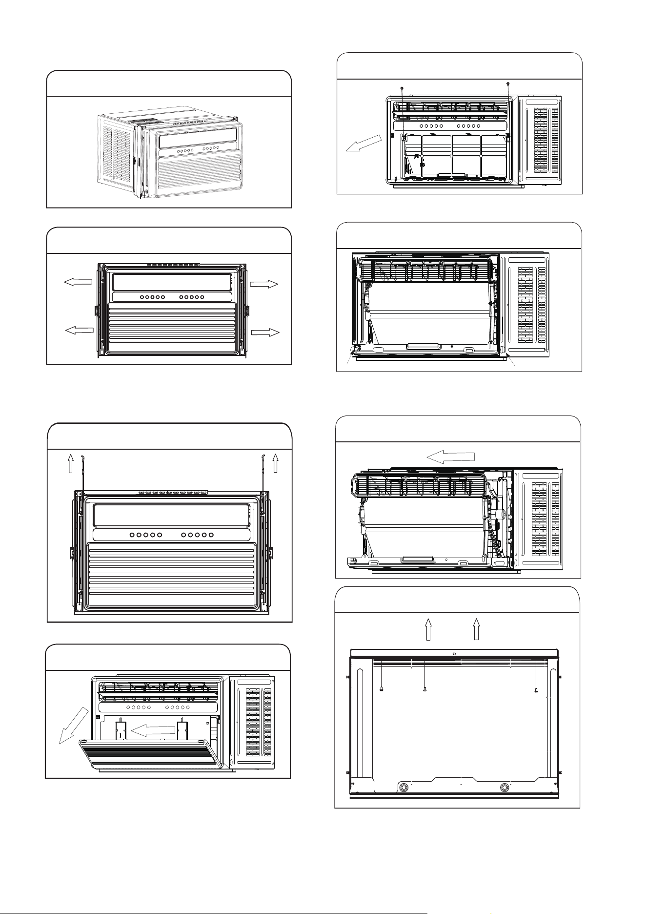
2.Remove filter and front panel
Pull down the front panel and remove the filter.
Lift the front panel up wards and remove from
the air conditioner.
3.Remove front panel and cabinet screws
Remove the four screws.
NOTES: The front panel screws must be
reinstalled beforemounting the air conditioner.
Remove the cable connecting the display board
4.Remove the connection
5.Remove chassis
Hold the cabinet while pulling on the base
handle to carefully remove the unit.
IMPORTANT: To avoid damage, do not pull
or lift near the topof the unit.
9
10
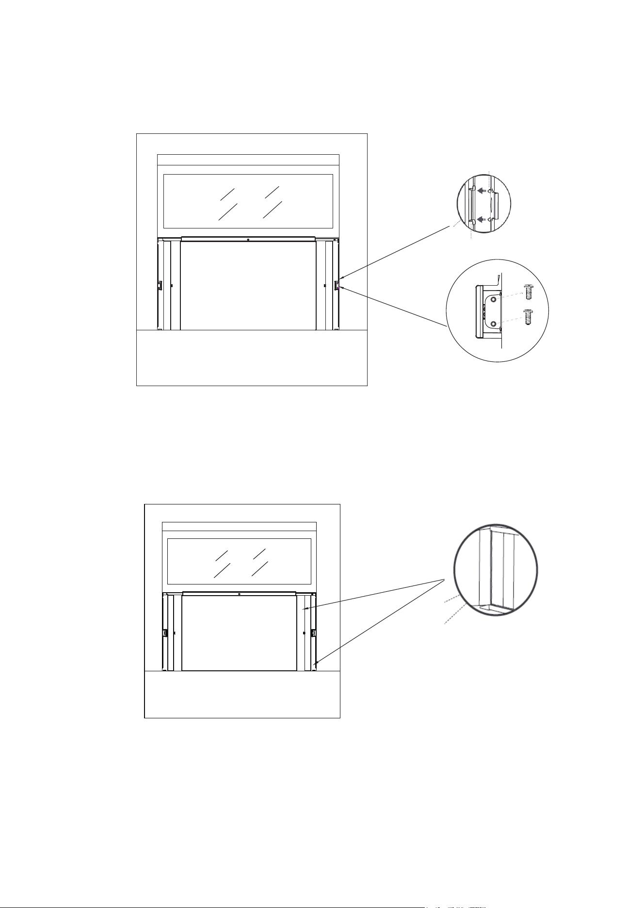
Step 5: Securing the Side Brackets
Extend the side brackets from both sides of the air conditioner onto the left and right window
frames and secure by installing four 3/4”screws as shown
NOTE:Fix the upper screws first, then the lower screws.
Step 3: Applying the Adhesive Foam Seal
Measure the length of the upper window frame, trim the adhesive foam seal to the appropriate
length, and apply as shown below.
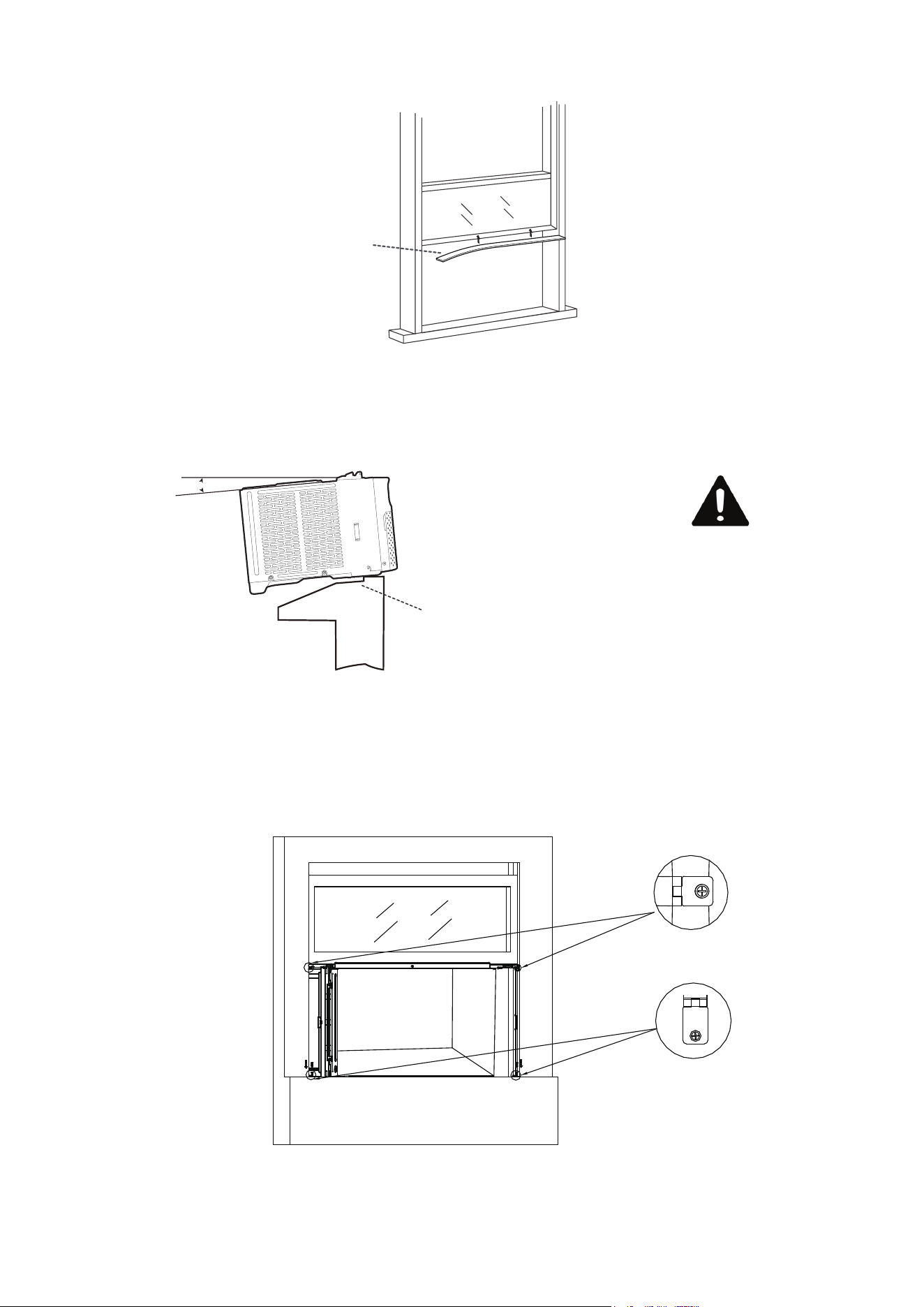
Step 4: Placing Inside an Open Window
Using team lift, carefully lift the air conditioner and place in the windowsill.
Next, close the window, making sure the air conditioner is centered and the bottom rail is flush
against the windowsill.
Note: The air conditioner should be tilted about 3° to allow for better drainage of condensate and
rainwater.Using a level, measure about 1/3 bubble for the correct slant.
Adhesive
Foam Seal
CAUTION
Be careful to avoid cuts
from the sharp metal edges
and aluminum fins on the
front and rear coils!
Outside Inside
Bottom
Rail
About 3°
11
Step 6: Securing the Side Panels
Pull the side panels inwards to align with the brackets, then secure onto the sides by snapping
the jutting points onto the locking pins.
The side panels should be locked by ¹⁄4” Long Hex-head Screw .
Step 7: Sealing Any Gaps with Modeling Clay (Plasticene)
Fill the crevices between the side brackets and panels with the included plasticene.
12
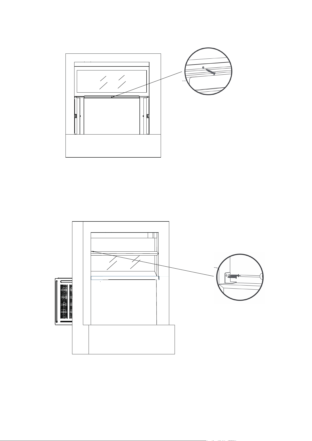
Step 8: Securing the Screw into the Top Rail
Secure the ¹⁄2" Screw into the top rail of the air conditioner to the window frame.
Step 9: Installing the Security Bracket (Recommended)
For security purposes, it is recommended to attach the security bracket to the top of the window using two
¹⁄2" screws to prevent opening the window from outside. However, the security bracket can be removed to
allow you to open the window when desired.
13
Install Support Brackets
1. Hold each support bracket flush ag ainst the outside of the window sill. Tighten each bracket to
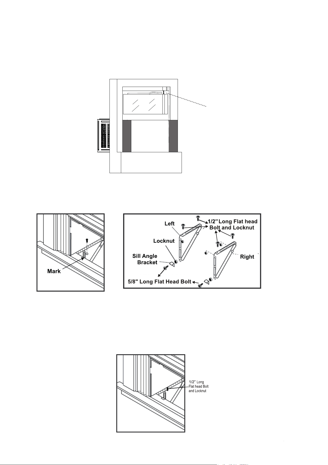
the bottom of the cabinet as shown below. Mark the brackets at top lever of the window sill and
then remove.
2. Assemble the sill angle brackets to the support brackets at the marked position as shown above.
Hand tighten, but not all the way for any changes that may need to be made later during
installation.
3. Install the support brackets (with sill angle brackets attached) to the bottom of the cabinet as
shown below.
4. Tighten all 6 bolts securely.
Step 10: Filling the Gap Between Sashes
Applying the Panel Seals
Trim the non-adhesive foam seal to the appropriate length and insert between the window sashes.
CAUTION: When open the window, besure that the fixed screws are avaliable from the curtain to
the window frame.
Measure the length extended by the side panels, trim the panel seals to the appropriate length,
peel off the backings and apply on the panels on both sides.
Non-Adhesive
Foam Seal
Panel Seals *2
14
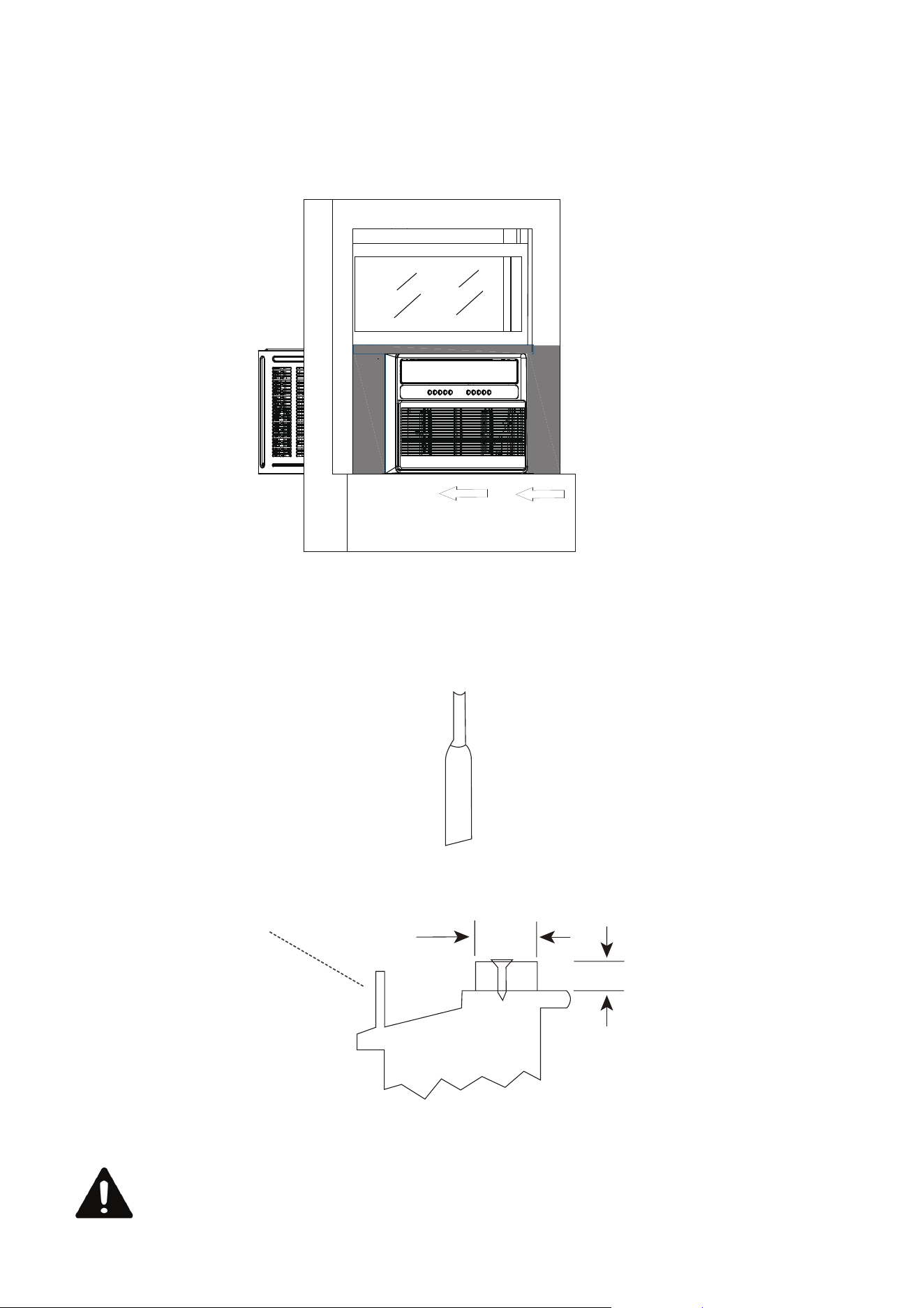
If AC is Blocked by Storm Window Frame
Add wood as shown above or remove store window frame/obstruction before installing the window
air conditioner.
If the Storm Window Frame must remain, be sure the drain holes or slots are not caulked or
painted shut.Accumulated rainwater or condensation must be allowed to drain out.
CAUTION
When opening the window, be sure that the fixed screws are secured properly in
place without any objects affecting their attachment to theside brackets and
associated window frame to prevent the unit from becoming unstable and falling.
SASH
INSIDE
1- 1/ 2”min
(38mm)
Storm window
frame or other
obstruction
Board thickness as
required, for proper
pitch to rear, along
entire sill.
Fasten with nails or
screws.
OUTSIDE
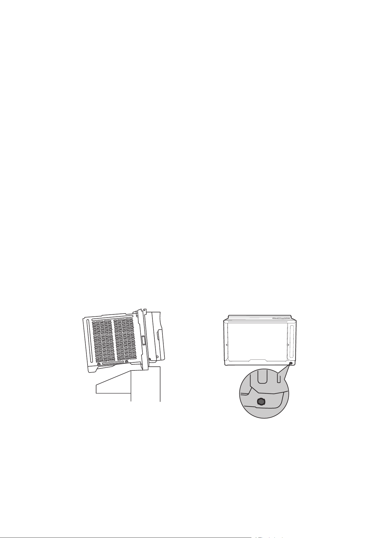
Installing the Chassis into the Cabinet
1. Team lift (two people) the air conditioner chassis and carefully slide it into the cabinet. Let the
front of the air conditioner hang out approximately 6".
2. CAUTION: DO NOT PUSH ON THE CONTROLS OR FINNED COILS.
3. Be sure the chassis is firmly seated in the back of the cabinet.
4. Insert all screws removed during window installation and reattach the front panel、air filter and
grille.
ASSEMBLY & INSTALLATION-THRU-THE-WALL (CONT.)
1.Unpack the Air Conditioner
Remove Left Telescopic Curtain Support Assy.
Remove Right Telescopic Curtain Support Assy.
2.Remove parts
3.Remove Hinge
4.Remove filter and front panel
5.Remove faceplate screws
Remove the two faceplate screws.
6.Remove case screws
Remove 2 screws fixed on left and right sides
of case and chassis
7.Remove chassis
8.Remove Upper guide rail
15
15K/18K/22K/24K
(435mm)
(650mm)
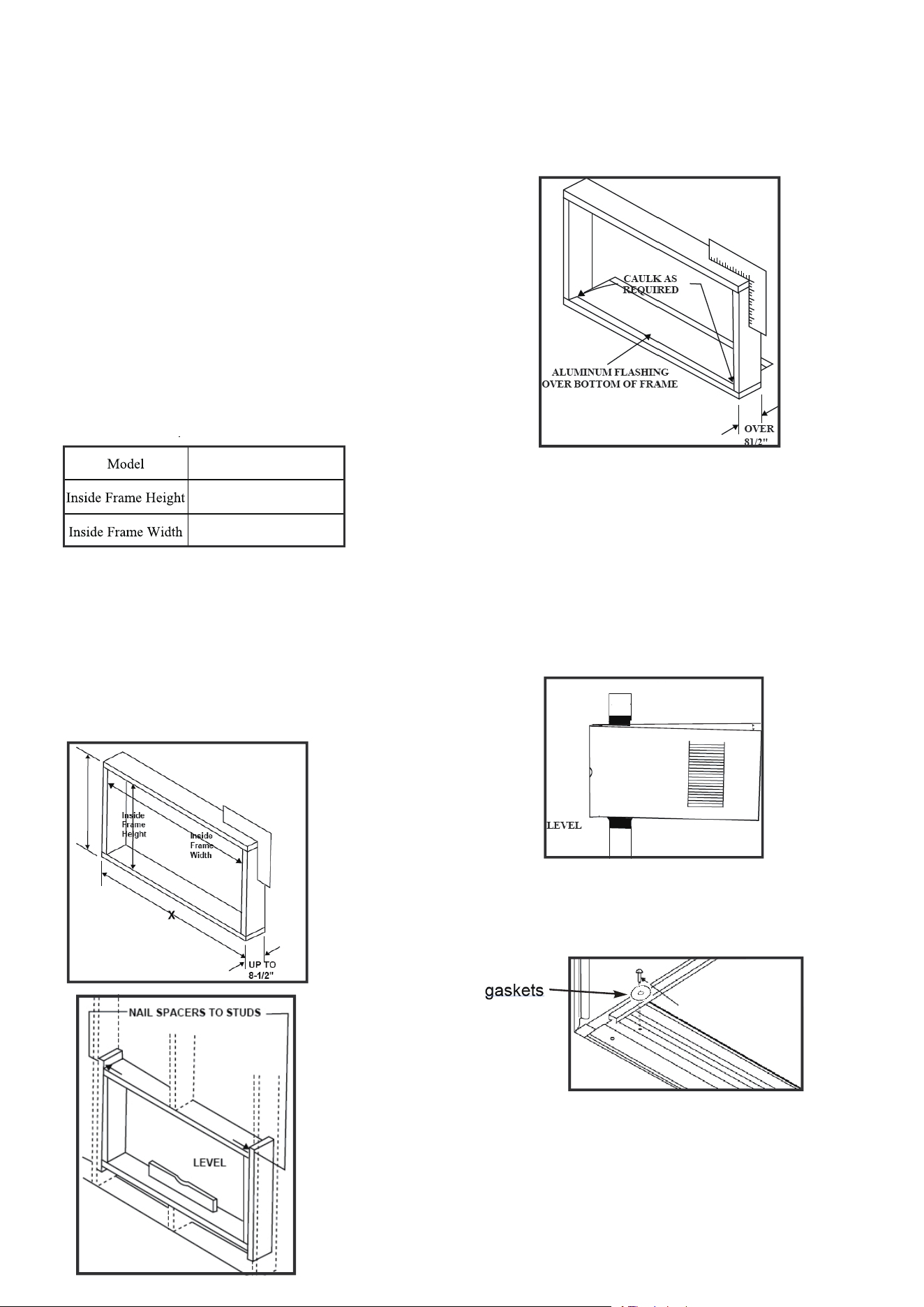
ASSEMBLY & INSTALLATION-THRU-THE-WALL (CONT.)
Prepare the Wall
1. Prepare the wall in frame construction
(including brickand stucco veneer).
Working from inside the room, find the wall
stud that is nearest the center of the
installation area.
2. Cut a hole on each side of the center stud.
3. Measure between the inside edges of every
other stud as shown below.
Carefully measure and cutan opening with
the following dimensions depending on your
model.
WIDTH"X"= inside modelplus twice the
thickness of theframing material used.
HEIGHTY" = inside modeleight plus twice the
thicknessof framing material used.
Y
4. Build a wooden frame withthe INSIDE
dimensions of your model isted above
(Measure twice).The frame depth should
be the same as the wall thickness. Fill in
extra space from the opening to the studs
with wood spacers as shown below.
5.Nail the spacers to the studs.They should
be flush with the dry wall.
NOTE: If wall thickness is 8-1/2" or more, add
aluminum flashing over the bottom of the
frame opening to assure water is unable to
enter the area between the inner and outer wall.
Prepare and Install the Cabinet
1. Slide the chassis from the cabinet. Refer
back to the REMOVE CHASSIS instructions
in the WINDOW MOUNTING SECTION.
2. Place the cabinet into the opening with the
bottom rail resting firmly on the bottom board
of the wood frame.
3. Position the cabinet so it is tilted properly
for water re-movalas seen below.
4.Secure the bottom rail to the wood frame
with two ¹⁄2” Long Hex-head Screws and
gaskets as shown below.
16
About 3°
¹⁄2” Long
Hex-head Screw
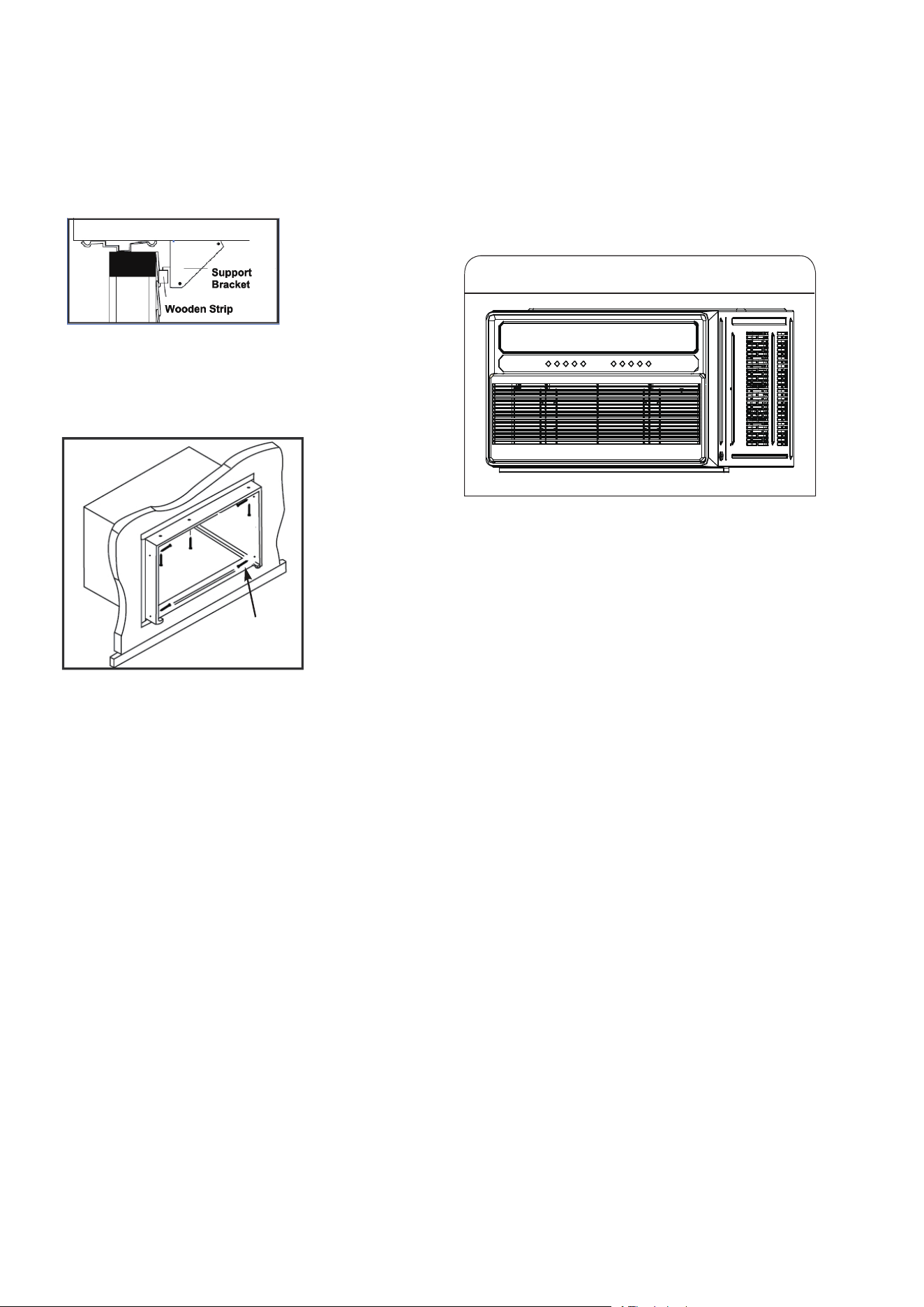
ASSEMBLY & INSTALLATION-THRU-THE-WALL (CONT.)
Refer to the SUPPORT BRACKET
ASSEMBLY in the WINDOW MOUNTING
section to assemble the support brackets.
A wooden strip nailed to the outside wall
should be used in conjunction with the
angled sill support brackets.
5. Screw or nail the cabinet to the wooden
frame using shims if the frame is oversized,
to eliminate possible noise Remember to
maintain proper slope for water elirnination.
6.Install the chassis into the cabinet by
following the steps described in the
WINDOW MOUNTING section.
OPTIONAL: Caulking and installation of the
trim on the interior wall may be done ifdesired.
Caulk the openings around the top and sides
of the cabinet and all sides of the wood sleeve
to the opening.
NOTE: See the WINDOW MOUNTING
instructions for the bottom rail seal location.
17
Push the whole machine into the outer box, fasten
the screws on both sides of the outer box, and
assemble the panels to complete the assembly of
the whole machine
Installing the Chassis into the Cabinet
⁵⁄16” Long
Hex-head Screw
Other Features
Filter Reminder
When the running time reaches 500 hours, the filter reminder will light up to indicate the filter
needs to be cleaned. Press and hold the Filter button for 5 seconds to reset the filter reminder.
Please see the maintenance section of this manual for filter cleaning instructions.
Display Auto Off
• Display will dim after 30 seconds (or after 15 seconds in sleep mode)
• Wake up the display by pressing any button
Memory
If the air conditioner is turned off but stays connected to the power,it will resume the previous
settings (except the timer setting) when it is turned on again.
Drain Water
This unit was designed to collect moisture from condensation in a collection pan in the base of
the unit. The collected water is distributed by the rear fan on to the condenser coil. This aids in the
overall efficiency of the unit.
It is normal to hear the water sloshing around when the fan is spinning.
If this behavior is not desired, the drain cap at the rear of the AC can be removed to drain a
portion of the water.Doing so may lessen the efficiency of the AC.A minimal amount of water will
still remain in the drain pan.
Window Requir
18
Inside
Outside
Maintenance
Care and Cleaning
Clean your air conditioner occasionally to keep it looking new. Before cleaning, be sure to
unplug the unit from any and all power sources to prevent electric shock or fire hazards.
Air Filter
The air filter should be checked at least once every month to see if it needs cleaning. Never
use hot water over 104°F (40°C) to clean the air filter. Never attempt to operate the unit without
the air filter. Trapped particles and dust can build up over time, which can result in decreased
airflow and can cause the coils to accumulate frost. To clean the air filter:
1. Pull the grille out from the indents on both sides at the front and remove the filter inside.
2. Wash the filter using liquid dish soap and warm water. Rinse the filter thoroughly. Gently
shake the filter to remove excess water.
3. Let the filter dry completely before placing it into the air conditioner.
Note: If you do not wish to wash the filter, you may vacuum the filter to remove the dust and
other particles.
Cabinet Cleaning
To clean the air conditioner’s cabinet:
• Using a cloth dampened in a solution of warm water and mild liquid soap, wipe down the unit
and the front panel. Then, using a clean dampened cloth, make sure to wipe down the unit to
remove all excess soap and continue to dry.
• Never use harsh cleaners, wax, or polish on the cabinet front.
• Be sure to wring out excess water from the cloth before wiping round the control. Excess water
may damage the unit.
Storage
If you want to store the unit when not in use, we recommend removing the drain plug at the back
of the unit and slightly tilting the unit towards the rear to drain any water in the pan in a safe
manner. Next, clean the unit and then store it back in the original packaging or box until next use.
19

Trouble shooting
20
PROBLEM POSSIBLE CAUSES SOLUTIONS
The air conditioner
will not start
The air conditioner is unplugged
Make sure the air conditioner plug
is pushed completely into the outlet.
The fuse is blown/circuit breaker is
tripped
Check the house fuse/circuit breaker
box and replace the fuse or reset the
breaker.
• The unit will automatically restart
when power is restored.
• There is a protective time delay
(approx. 3 minutes) to prevent
tripping and overloading the
compressor. For this reason, the unit
may not start normal cooling for 3
minutes after it is turned back on.
Power failure
The current interrupter device is
tripped
• Press the RESET button located on
the power cord plug.
• If the RESET button will not stay
engaged, discontinue use of the
airconditioner and contact a qualified
service technician.
The air conditioner
does not cool as it
should
Air flow is restricted
Make sure there are no curtains,
blinds or furniture blocking the front
of the air conditioner.
The temperature control may not
be set correctly.
Lower the set thermostat
temperature.
The air filter is dirty
Clean the filter. Refer to
MAINTENANCE.
The room may be too warm
Please allow time for the room to
cool down after turning on the air
conditioner.
Cold air is escaping
Check for open furnace registers
and cold air returns.
The cooling coils are frozen
Switch to high fan speed and set the
thermostat to a higher temperature.
Temperature sensor is not well
situated.
Temperature sensor behind the air
filter is touching the coil. Try to move
it so it does not contact the cold coil.

21
The air conditioner
is freezing up
Ice blocks the air flow and stops the
air conditioner from cooling the
room
Switch to high fan speed and set the
thermostat to a higher temperature.
The batteries are inserted
incorrectly
Replace the batteries.The batteries may be dead
The remote control
is not working
Check the position of the batteries.
Water is dripping
outside
Hot and humid weather This is normal.
Water is dripping
INSIDE when the
unit is cooling
The air conditioner is not
correctly tilted outside
Improper installation. Tilt air
conditioner slightly to the outside
to allow water drainage. Refer to
installation instructions.
Water is dripping
INSIDE when the
unit is cooling
Moisture removed from the air is
draining into the base pan
This is normal for a short period in
areas with low humidity and normal
for a longer period in areas with high
humidity
Noise when the
unit starts
A "da-da" sound may occur for 30
seconds when the unit is turned
on due to the compressor starting.
This is normal.