p/n: P-164000628
Revision 05
For use with the Following:
Eaton 9155 UPS (8–15kVA)
Eaton 9170+ UPS (3–18kVA)
Eaton 9PX Split-Phase UPS (6–10kVA)
Eaton 9PXM Split Phase UPS (4–20kVA)
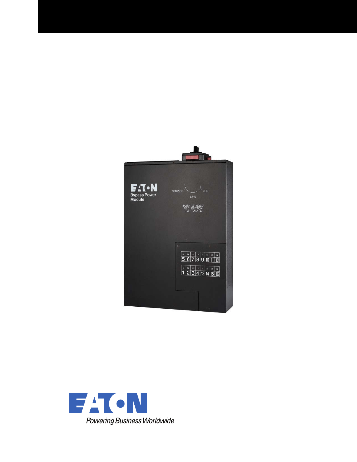
Eaton Bypass Power Module (BPM) Users Guide

©Copyright 2022 Eaton, Raleigh, NC, USA. All rights reserved. No part of this document may be reproduced in any way without the
express written approval of Eaton.
SSppeecciiaall SSyymmbboollss
The following are examples of symbols used on the product to alert you to important information:
RISK OF ELECTRIC SHOCK - Observe the warning associated with the risk of
electric shock symbol.
CAUTION: REFER TO OPERATOR'S MANUAL - Refer to your operator's
manual for additional information, such as important operating and maintenance
instructions.
This symbol indicates that you should not discard the product in the trash. This
product must be disposed of properly. For more information, contact your local
recycling/reuse or hazardous waste center.
This symbol indicates that you should not discard waste electrical or electronic
equipment (WEEE) in the trash. For proper disposal, contact your local recycling/
reuse or hazardous waste center.
!
IMPORTANT
To ensure you have the most up-to-date content and information for this product, please review the
latest manual revision on our website, www.eaton.com.

User’s Guide P-164000628 P-164000628—Rev 05 iii
TTaabbllee ooff CCoonntteennttss
11 IInnttrroodduuccttiioonn....................................................................................................................................................................................................................................................................................................11
1.1 Introduction...............................................................................................................................................1
1.2 Bypass Overview ....................................................................................................................................... 1
22 IInnssttaallllaattiioonn ......................................................................................................................................................................................................................................................................................................33
2.1 Installation ................................................................................................................................................ 3
2.2 Bypass Power Module Dimensions ................................................................................................................ 3
2.3 Rackmount Installation ................................................................................................................................4
2.4 Wallmount BPM Installation.......................................................................................................................... 6
2.5 Input Current and Wire Ratings......................................................................................................................7
2.6 Signal Wire Routing..................................................................................................................................... 8
33 BBPPMM ttoo UUPPSS CCoonnnneeccttiioonn DDiiaaggrraammss................................................................................................................................................................................................................................ 1111
3.1 Eaton 9155 UPS to BPM Connection Diagram ................................................................................................ 11
3.2 Eaton 9170+ UPS to BPM Connection Diagram .............................................................................................. 12
3.3 9PX Split Phase UPS to BPM Connection Diagram .......................................................................................... 13
3.4 Eaton 9PXM UPS Connection Diagram.......................................................................................................... 14
44 OOppeerraattiioonn........................................................................................................................................................................................................................................................................................................ 1155
4.1 No Break Transfer from UPS Mode to Service Mode ........................................................................................ 15
4.2 Lock-out/Tag-out ...................................................................................................................................... 16
4.3 No Break Transfer from Service Bypass to UPS Mode ...................................................................................... 16
55 SSppeecciiffiiccaattiioonnss.......................................................................................................................................................................................................................................................................................... 1199

iv User’s Guide P-164000628 P-164000628—Rev 05
Table of Contents

User’s Guide P-164000628 P-164000628—Rev 05 v
LLiisstt ooff FFiigguurreess
Figure 1. BPM Dimensions (in millimeters)....................................................................................................... 3
Figure 2. Install Rail Kit.................................................................................................................................4
Figure 3. Push BPM into the Rack .................................................................................................................. 4
Figure 4. Remove the Wire Access-Point Covers ............................................................................................... 5
Figure 5. Remove the Access Panel Cover ....................................................................................................... 5
Figure 6. Install the Mounting Ears ................................................................................................................. 5
Figure 7. Secure the BPM to the Rack............................................................................................................. 6
Figure 8. BPM with Wallmount Brackets .........................................................................................................6
Figure 9. BPM Hardwired Overview ...............................................................................................................7
Figure 10. Signal Wire RoutingSignal Wire Routing .............................................................................................. 9
Figure 11. Eaton 9155 UPS to BPM Connection Diagram Using Signal Inputs.......................................................... 11
Figure 12. Eaton 9170+ UPS to BPM Connection Diagram With Signal Inputs ......................................................... 12
Figure 13. 9PX Split Phase UPS to BPM Connection Diagram with Signal Inputs...................................................... 13
Figure 14. 9PXM UPS Connection Diagram with Signal Inputs ............................................................................. 14
Figure 15. From UPS to LINE ........................................................................................................................ 15
Figure 16. From LINE to SERVICE.................................................................................................................. 16
Figure 17. LOTO Feature ............................................................................................................................. 16
Figure 18. From SERVICE to LINE.................................................................................................................. 17
Figure 19. From Line to UPS ......................................................................................................................... 17

vi User’s Guide P-164000628 P-164000628—Rev 05
List of Figures

User’s Guide P-164000628 P-164000628—Rev 05 vii
LLiisstt ooff TTaabblleess
Table 1. BPM Positions ................................................................................................................................ 1
Table 2. RBPM Terminal Block Sizing .............................................................................................................. 8

viii User’s Guide P-164000628 P-164000628—Rev 05
List of Tables

User’s Guide P-164000628 P-164000628—Rev 05 1
CChhaapptteerr 11 IInnttrroodduuccttiioonn
11..11 IInnttrroodduuccttiioonn
The Eaton® Bypass Power Module (BPM) is designed to be a maintenance bypass switch that also contains
flexible output power distribution and mounting options. The BPM is a bypass module that can be used with a
variety of Eaton UPS models including the 9170+, 9155, and 9PX SP.
The BPM provides added reliability to Eaton uninterruptable power supply (UPS) systems by ensuring
seamless, uninterrupted, no-break transfer as well as a lock-out/tag-out (LOTO) feature to ensure the greatest
safety for UPS technicians and electricians. The BPM also offers output distribution in order to simplify wiring in
a rackmount IT environment, potentially removing the need for a panelboard, breakers, and conduit for
distribution.
Although the BPM is designed to be safe, the bypass can carry high levels of voltage and current. The BPM
should only be operated by an experienced user, familiar with UPS behavior and functionality. Installation for
models requiring hardwire connections should be performed by a qualified electrician following local electrical
codes. Please refer to the installation chapter of your UPS manual for the BPM wiring diagram.
11..22 BByyppaassss OOvveerrvviieeww
The BPM has three operating positions (see Table 1). Failure to understand the correct bypass sequence and
position may cause the critical load to be dropped. Consider both the operating state of the UPS and the BPM
when protecting your critical loads.
NOTE In the UPS or LINE position, AC input power is still connected to the input terminals
inside the UPS.
Table 1. BPM Positions
Switch
Position
Description
UPS The normal operating state of the system occurs when the BPM switch is
in the UPS position. Utility power is fed to the bypass, where power is then
fed to the UPS. The UPS provides critical battery backup and power
conditioning and power is then fed back to the bypass switch and then the
critical load.

2 User’s Guide P-164000628 P-164000628—Rev 05
Table 1. BPM Positions (Continued)
LINE When the switch is in the LINE position, utility power is directly connected
to the critical load and the output of the UPS is disconnected. In this state
the UPS remains powered, which is often beneficial for troubleshooting,
obtaining logs, or updating firmware.
SERVICE Like the LINE position, the SERVICE position connects the load directly to
AC input power and disconnects UPS output; however, because SERVICE
also disconnects AC input from the UPS, this is the appropriate position for
UPS maintenance or repair. In the SERVICE position, the UPS can be
completely removed from the system.
Bypass Overview

User’s Guide P-164000628 P-164000628—Rev 05 3
CChhaapptteerr 22 IInnssttaallllaattiioonn
22..11 IInnssttaallllaattiioonn
Risk of electrical shock. Only qualified service personnel (such as a licensed electrician) should perform the
electrical installation.
To prevent electrical shock or damage to the equipment, verify that the Eaton UPS is OFF before you remove
the entrance panel. The circuit breaker or disconnect switch must also be off at the AC input service panel.
Also, turn OFF the AC disconnect and bypass switches before you connect any wires to the bypass switch
terminal strip.
22..22 BByyppaassss PPoowweerr MMoodduullee DDiimmeennssiioonnss
Figure 1 shows the dimensions of the Bypass Power Module (BPM) in millimeters (inches).
Figure 1. BPM Dimensions (in millimeters)
0.0
0.0
0.0
130.1
(5.1)
603
(23.7)
663
(26.1)
440
(17.3)

4 User’s Guide P-164000628 P-164000628—Rev 05
22..33 RRaacckkmmoouunntt IInnssttaallllaattiioonn
• The BPM distributes high density power in a small form factor.
• Read the complete installation procedure before beginning any electrical wiring.
To install the BPM in a rack:
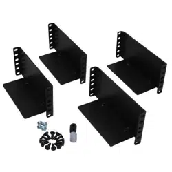
1. Install the 4-post rail kit included with the BPM (see Figure 2).
Figure 2. Install Rail Kit
2. Place the BPM on the rails and push the BPM into the rack.
Verify that the breakers are facing the front of the rack and the BPM wiring terminals are facing the rear of
the rack.
3. Push the BPM past the back of the rack to allow access to the rear wire access-point covers and the wire
access panel cover (see Figure 3).
Figure 3. Push BPM into the Rack
4. Remove the wire access-point covers (see Figure 4).
Rackmount Installation

User’s Guide P-164000628 P-164000628—Rev 05 5
Figure 4. Remove the Wire Access-Point Covers
5. Remove the access panel cover (see Figure 5).
Figure 5. Remove the Access Panel Cover
6. To wire the BPM, .
7. After wiring is complete, replace the covers removed in Step 4 and Step 5.
8. Push the BPM past the front of the rack to allow access for the mounting ears installation.
9. Install the mounting ears to the BPM using the provided screws (see Figure 6).
Figure 6. Install the Mounting Ears
10. Push the BPM into the rack and secure the mounting ears to the rack using the provided screws (see
Figure 7).
Rackmount Installation

6 User’s Guide P-164000628 P-164000628—Rev 05
Figure 7. Secure the BPM to the Rack
22..44 WWaallllmmoouunntt BBPPMM IInnssttaallllaattiioonn
• The BPM distributes high density power in a small form factor.
• Read the complete installation procedure before beginning any electrical wiring.
To install the BPM in a wallmount form factor:
1. Select a mounting location for the bypass switch within sight of the UPS.
NOTE The bypass switch should be mounted securely to a sturdy surface. You may need to
turn the cabinet 90 degrees (on its side) to enable operator access to the switch handle.
2. Use the provided wallmount brackets to firmly secure the BPM to the wall (Figure 8).
Figure 8. BPM with Wallmount Brackets
3. Remove the six (6) screws on the BPM front cover and remove the cover.
Remove any packing material inside the BPM.
4. Remove the knockouts in the bottom of the BPM as needed for wiring (see Figure 9).
Wallmount BPM Installation

User’s Guide P-164000628 P-164000628—Rev 05 7
Figure 9. BPM Hardwired Overview
Wire routing
Refer to UPS manuals for proper
wiring connections
Auxillary Single UPS Contacts
Refer to UPS manuals for proper
wiring connections
Remove cover to gain
access to the wiring
terminal blocks
MBP
INPUT
WIRING
5. To wire the BPM, see 2.6 Signal Wire Routing .
6. After wiring is complete, replace the cover removed in Step 3.
22..55 IInnppuutt CCuurrrreenntt aanndd WWiirree RRaattiinnggss
Wiring to the BPM varies based on the UPS selection. Refer to the UPS manual for recommended input
breaker size. To easily expand the system, it is recommended that initial installation of the BPM and UPS
contains wiring to support the maximum capacity of the UPS system. For example, if the UPS is now designed
to be a 12 kVA system with an 80A input, but can be expanded to 18 kVA requiring 125A input in the future,
then 125A wiring would be used initially to prevent rewiring costs during future expansion.
Local electrical codes should always be followed, but be sure to check with the terminal block sizing on both
the UPS and the BPM. The UPS terminal block sizing can be found in the UPS manual, while the BPM terminal
block sizing can be found in Table 2.
Input Current and Wire Ratings

8 User’s Guide P-164000628 P-164000628—Rev 05
Table 2. RBPM Terminal Block Sizing
BPM Terminal Block
Sizing
75°C Copper Wire Size Conductor Screw Torque
Wire Size Range
BPM 125A Models
42.1 mm
2
(1 AWG) 6.6 Nm (50 lb in) 10 - 1/0 AWG
BPM 30A Models
8.4 mm
2
(8 AWG) 4.5 Nm (40 lb in) 14 - 6 AWG
!
IMPORTANT
FOR U.S. INSTALLATIONS, READ THIS IMPORTANT NOTE
• Table 2 lists the mm
2
and AWG wire size for each circuit breaker size shown on the wiring diagrams. The
minimum recommended circuit breaker sizes for each model and voltage application are listed on the
wiring diagrams.
• Conductor sizes shall be no smaller than the 75°C wire size based on the ampacities given in Table 310–
16 of the National Electrical Code® (NEC®), ANSI/NFPA 70-1999, and article 220. All circuit conductors,
including the neutral conductor, must be the same size (ampacity) wire. Code may require a larger AWG
size than shown in this table because of temperature, number of conductors in the conduit, or long service
runs. Follow local code requirements.
22..66 SSiiggnnaall WWiirree RRoouuttiinngg
The auxiliary contacts must be wired to the BPM from the UPS for proper functionality. These auxiliary contacts
signal the UPS to go to Internal Bypass mode to provide a synchronized transfer. Failure to wire the auxiliary
contacts can be dangerous and result in system failure. Check the UPS users guide that is being used with the
BPM for specific contact functionality.
NOTE 1 Refer to the UPS manual and “Input Current and Wire Ratings” on page 11 for breaker,
terminal block, and wire sizing.
NOTE 2 Provide enough flexibility in the conduit for the BPM to be firmly mounted in the rack.
NOTE 3 Connection diagrams can be found on pages 11–14 for wiring details.
To route signal wires (customer supplied):
1. Route the signal wires through the provided insulation.
2. Pass the insulated wires through the opening in the rear panel (Figure 10).
3. Connect terminal blocks to signal wires.
4. Plug in the terminal blocks into their proper locations.
5. Place the insulated wires into the two wire clips as shown.
Signal Wire Routing

User’s Guide P-164000628 P-164000628—Rev 05 9
Figure 10. Signal Wire RoutingSignal Wire Routing
Signal Wire
Openin
g
Rear of
BPM
Wire
Clips
Signal Wirings
Terminal
Blocks
Insulation
Signal Wire Routing

10 User’s Guide P-164000628 P-164000628—Rev 05
Signal Wire Routing

User’s Guide P-164000628 P-164000628—Rev 05 11
CChhaapptteerr 33 BBPPMM ttoo UUPPSS CCoonnnneeccttiioonn DDiiaaggrraammss
33..11 EEaattoonn 99115555 UUPPSS ttoo BBPPMM CCoonnnneeccttiioonn DDiiaaggrraamm
Figure 11. Eaton 9155 UPS to BPM Connection Diagram Using Signal Inputs
1 2 3 4
5
6
7 8
AC TO
UPS INPUT
AC FROM
UPS OUTPUT
L2 N L1
L2 N L1
Input
Output
1 2 3 4
5
6
7
8
L2
N L1
L2 N L1
AC TO LOADS
CABLES FROM UPS AND AC
INPUT/OUTPUT THROUGH BPM
BOTTOM ACESS PLATE
AC LINE INPUT
BPM Signal
Terminals
Install conduit
over signal wires
To Signal
Input 1
To Signal
input 2
BPM Signal
Terminals
To Signal input 1
Two Connector Option
One Connector Option
Note: The signal inputs must be programmed via the keypad on the UPS
White Wire
Red and
White Wires
Black Wire
Red and
Black Wires
White and
Black Wires
Red and
Black Wires
White and
Black Wires
Red and
Black Wires
UPS Terminal Block
To Load
To Utility
Lower BPM Terminal Block
Upper BPM Terminal Block

12 User’s Guide P-164000628 P-164000628—Rev 05
33..22 EEaattoonn 99117700++ UUPPSS ttoo BBPPMM CCoonnnneeccttiioonn DDiiaaggrraamm
Figure 12. Eaton 9170+ UPS to BPM Connection Diagram With Signal Inputs
1 2 3 4
5
6
7 8
AC TO
UPS INPUT
AC FROM
UPS OUTPUT
L2 N L1
L2 N L1
1 2 3 4
5
6
7
8
L2
N L1
L2 N L1
AC TO LOADS
CABLES FROM UPS AND AC
INPUT/OUTPUT THROUGH BPM
BOTTOM ACESS PLATE
AC LINE INPUT
To Load
To Utility
+DC
X3
X2
X1
N
-DC
9170+ Output Terminals
3
2
1
9170+ Input Terminals
BPM Signal
Terminals
(Install conduit
over signal wires)
UPS Signal
Terminals
1
2
3
4 5 6
Signal Common
External Bypass
*(short to common when active)
Black Wire
Red Wire
Red Wire
Black Wire
Upper BPM Terminal Block
Lower BPM Terminal Block
Eaton 9170+ UPS to BPM Connection Diagram

User’s Guide P-164000628 P-164000628—Rev 05 13
33..33 99PPXX SSpplliitt PPhhaassee UUPPSS ttoo BBPPMM CCoonnnneeccttiioonn DDiiaaggrraamm
Figure 13. 9PX Split Phase UPS to BPM Connection Diagram with Signal Inputs
1 2 3 4
5
6
7 8
AC TO
UPS INPUT
AC FROM
UPS OUTPUT
L2 N L1
L2 N L1
1 2 3 4
5
6
7
8
L2
N L1
L2 N L1
AC TO LOADS
CABLES FROM UPS AND AC
INPUT/OUTPUT THROUGH BPM
BOTTOM ACESS PLATE
AC LINE INPUT
L1 N L2 L1 N
L2
UPS Output
UPS Input
BPM Signal
Terminals
(Install conduit
over signal wires)
To ROO/MBP
Black Wire
Red Wire
Black Wire
Red Wire
To Utility
To Load
Upper BPM Terminal Block
Lower BPM Terminal Block
9PX Split Phase UPS to BPM Connection Diagram

14 User’s Guide P-164000628 P-164000628—Rev 05
33..44 EEaattoonn 99PPXXMM UUPPSS CCoonnnneeccttiioonn DDiiaaggrraamm
Figure 14. 9PXM UPS Connection Diagram with Signal Inputs
1 2 3 4
5
6
7 8
AC TO
UPS INPUT
AC FROM
UPS OUTPUT
L2 N L1
L2 N L1
1 2 3 4
5
6
7
8
L2
N L1
L2
N L1
AC TO LOADS
CABLES FROM UPS AND AC
INPUT/OUTPUT THROUGH BPM
BOTTOM ACESS PLATE
AC LINE INPUT
To Load
To Utility
L1
L2
N
L1
L2
N
9PXM Output Terminals 9PXM Input Terminals
(Install conduit
over signal wires)
BPM Signal
Terminals
** Set the value of “Signal Input 1 and Signal Input 2” through the UPS front display to “Normally Open”. **
White Wire
White Wire
Black Wire
Red Wire
Red Wire
Black Wire
Upper BPM Terminal Block
Lower BPM Terminal Block
Eaton 9PXM UPS Connection Diagram

User’s Guide P-164000628 P-164000628—Rev 05 15
CChhaapptteerr 44 OOppeerraattiioonn
44..11 NNoo BBrreeaakk TTrraannssffeerr ffrroomm UUPPSS MMooddee ttoo SSeerrvviiccee MMooddee
It is critical that the following steps are followed to ensure correct and safe operation.
Do not attempt to push the red interlock button or attempt to move the bypass switch handle if the UPS is
operating on battery power.
Refer to the UPS user guide or call the Eaton service help desk for specific BPM to UPS signal functionality.
To turn the BPM to SERVICE:
1. Press and hold the red button and turn the switch to LINE (see Figure 15).
NOTE Pressing the red button sends the UPS into Internal Bypass mode. This allows the UPS
output to synchronize with utility for safe, uninterrupted transfer.
The UPS is now in LINE mode. The critical load is fed directly from utility and the UPS remains energized
from utility power. The UPS may be left in this mode while trying to troubleshoot, gather alarms from the
UPS, or perform other preventative maintenance activities.
Figure 15. From UPS to LINE
2. Turn the switch from LINE to SERVICE (see Figure 16). The critical load is fed directly from utility and the
UPS is now completely disconnected from AC power. Ensure that the UPS is off and the terminals are
completely de-energized before performing any maintenance on the UPS.

16 User’s Guide P-164000628 P-164000628—Rev 05
Figure 16. From LINE to SERVICE
44..22 LLoocckk--oouutt//TTaagg--oouutt
The BPM comes with a Lock-out/Tag-out (LOTO) feature to keep the BPM bypass switch locked in SERVICE
mode while qualified service personnel works on the UPS. To use the LOTO feature:
1. Press and hold the red bar (see ).
Figure 17. LOTO Feature
2. Install a lock and tag in any opening at the base of the switch according to LOTO procedures.
3. Remove the lock and tag to reset the LOTO position.
44..33 NNoo BBrreeaakk TTrraannssffeerr ffrroomm SSeerrvviiccee BByyppaassss ttoo UUPPSS MMooddee
After the system has been placed into SERVICE mode, it must be returned to UPS state to resume normal
operation.
It is critical that the following steps are followed to ensure correct and safe operation.
Do not attempt to push the red interlock button or attempt to move the bypass switch handle if the UPS is
operating on battery power.
Refer to the UPS user guide or call the Eaton service help desk for specific BPM to UPS signal functionality.
Lock-out/Tag-out

User’s Guide P-164000628 P-164000628—Rev 05 17
To turn the BPM to UPS mode:
1. Turn the switch from SERVICE to LINE (see Figure 18).
The UPS is now in LINE mode and is energized. It is often best practice to check the UPS status and
configure settings in this mode before transitioning to UPS mode. Simply check the status of the UPS
through the front LCD menu to ensure the UPS is prepared for use.
Figure 18. From SERVICE to LINE
1
2. To transition the UPS from LINE to UPS, press and hold the red button and turn the switch to UPS (see ).
NOTE 1 Pressing the red button sends the UPS into Internal Bypass mode. This allows the UPS
output to synchronize with utility for safe, uninterrupted transfer.
NOTE 2 In UPS mode, the UPS resets from Internal Bypass to UPS Normal mode ( online mode
). This transition may take as long as 60 seconds.
NOTE 3 Do not attempt to push the red interlock button or attempt to move the bypass switch
handle if the UPS is operating on battery power.
Figure 19. From Line to UPS
2 3
3. Once the switch is in UPS mode and the UPS is in Normal mode (online mode), the system is in normal
operation and prepared to provide uninterrupted power to the critical load.
No Break Transfer from Service Bypass to UPS Mode

18 User’s Guide P-164000628 P-164000628—Rev 05
No Break Transfer from Service Bypass to UPS Mode

User’s Guide P-164000628 P-164000628—Rev 05 19
CChhaapptteerr 55 SSppeecciiffiiccaattiioonnss
55..11 WWeeiigghhttss aanndd DDiimmeennssiioonnss
This chapter provides the following specifications:
• Dimensions and weights
• Electrical connections
• Rear Panel Outlet Options
Table 3. Weights and Dimensions
Model
Dimensions HXWXD (mm/inch)
Weight (kg/lb)
BPM125XX 130 x 440 x 663 / 5.1 x 17.3 x 26.1 17/38
Table 4. Input Connection Type
Model
Input Connection
BPM125XX
Hardwired (L1, L2, N, G)
Figure 20. Rear Panel Outlet Options
L14-30R
L6-30R
L6-20R
5-20R
C19 Blank
Panel 1 Panel 2

P-16400062805
P-164000628 05