
perator's
I:RnFrSMRN°
LAWN TRACTOR
21 HP, Variation Speed
46" Deck
Model No. 247.288852
• Espanol, P. 58
This product has a low emission engine which operates differently
from previously built engines. Before you start the engine, read and
understand this Operator's Manual.
Before using this equipment,
read this manual and follow
all safety rules and operating
instructions.
For answers to your questions about
this product, Call:
1-800=659=5917
Craftsman Tractor Help Line
7 am = 7 pm CT, Mort. =Sun.
Sears Brands Management Corporation, Hoffman Estates, IL 60179 U.S.A.
Visit our website: www.craftsman.com FormNo.769-06474D
(February3,2012)

Warranty Statement .......................................................... 2
Safety Instructions ............................................................ 3
Slope Gauge ..................................................................... 8
Assembly ........................................................................... 9
Operation ........................................................................ 11
Service and Maintenance .............................................. 17
Off-Season Storage ........................................................ 26
Trou bleshooting .............................................................. 27
Labels ............................................................................. 28
Parts List ......................................................................... 30
Espa_ol ............................................................................ 58
Service Numbers ............................................. Back Cover
CRAFTSMAN FULL WARRANTY
FORTWOYEARSfromthe dateof purchase,all non-expendablepartsof thisridingequipmentarewarrantedagainstany defectsin material
orworkmanship.A defectivenon-expendablepartwill receivefreein-homerepairor replacementif repairis impossible.
FORFIVEYEARSfromthedateof purchase,the frameof thisridingequipmentis warrantedagainstanydefects in materialor workmanship.
Adefectiveframewill receivefreein-homerepairor replacementif repairis impossible.
FORTENYEARSfromthe dateof purchase,the frontaxleof thisridingequipmentis warrantedagainstany defectsin materialorworkman-
ship.A defectivefront axle will receivefree in-homerepairor replacementif repairis impossible.
FOR90 DAYSfromthe dateof purchase,the battery(anexpendablepart)of this ridingequipmentis warrantedagainstanydefects in material
orworkmanship(ourtestingprovesthatit will not holdacharge).A defectivebatterywill receivefree in-homereplacement.
ADDiTiONAL LiFETiMELiMiTEDWARRANTYon CAST iRONFRONTAXLE(if equipped)
FORAS LONGASIT IS USEDbythe originalownerafter the tenthyearfrom the dateof purchase,thecast ironfront axle(if equipped)of
thisridingequipmentiswarrantedagainst anydefectsinmaterialor workmanship.Withproofof purchase,a defectivecast ironfront axlewill
receivefreein-homereplacement.
WARRANTYSERVICE
Forwarrantycoveragedetails toobtainfree repairor replacement,call 1-800-659-5917orvisit the website: www.craftsman.corn
In all casesabove,if part repairor replacementisimpossible,the ridingequipmentwill be replacedfreeof chargewith the sameor an
equivalentmodel.
Allof theabovewarrantycoverageisvoidifthisridingequipmentiseverusedwhileprovidingcommercialservicesorif rentedto anotherperson.
This warrantycovers ONLYdefects in materialandworkmanship. Warranty coverage does NOTinclude:
• Expendableparts(exceptbattery)that canwearout from normalusewithinthe warrantyperiod,includingbut not limitedto blades,
sparkplugs,aircleaners,belts,andoil filters.
• Standardmaintenanceservicing,oilchanges,or tune-ups.
• Tire replacementor repaircausedby puncturesfromoutsideobjects,suchas nails,thorns,stumps,or glass.
• Tireor wheelreplacementor repairresultingfromnormalwear,accident,orimproperoperationor maintenance.
• Repairsnecessarybecauseof operatorabuse,includingbutnot limitedto damagecausedby towingobjectsbeyondthe capabilityof
the ridingequipment,impactingobjectsthat bend theframe,axleassemblyor crankshaft,or over-speedingthe engine.
• Repairsnecessarybecauseof operatornegligence,includingbut not limitedto,electricalandmechanicaldamagecausedby
improperstorage,failureto usethe propergradeandamountof engineoil, failureto keepthe deckclearof flammabledebris, or
failureto maintainthe ridingequipmentaccordingto the instructionscontainedinthe operator'smanual.
• Engine(fuelsystem)cleaningor repairscausedbyfuel determinedto be contaminatedor oxidized(stale).In general,fuel shouldbe
usedwithin30 daysof itspurchasedate.
• Normaldeteriorationandwearof the exteriorfinishes,or productlabelreplacement.
Thiswarrantygivesyou specificlegalrights,and youmayalsohaveotherrights whichvary from stateto state.
Sears Brands ManagementCorporation, Hoffman Estates, IL 60179
EngineOil: SAE30
Fuel: UnleadedGasoline
SparkPlug: Champion®RC12YC
Engine: Briggs& Stratton
ModelNumber:
Serial Number:
Dateof Purchase:
Recordthe modelnumber,serialnumber,
anddateof purchaseabove.
© KCD IR LLC 2
Thissymbolpointsout importantsafetyinstructionswhich,if not
followed,couldendangerthepersonalsafetyand/orpropertyof
yourselfandothers. Readandfollowall instructionsin thismanual
beforeattemptingto operatethismachine.Failureto complywith
theseinstructionsmayresultin personalinjury.Whenyou seethis
symbol,HEEDITS WARNING!
CALIFORNIA PROPOSITION 65
EngineExhaust,someof its constituents,and certainvehicle
componentscontainor emit chemicalsknownto Stateof California
to cause cancerandbirthdefectsorother reproductiveharm.
Batteryposts,terminals,and relatedaccessoriescontainleadand
leadcompounds,chemicalsknownto the Stateof Californiato
causecancerand reproductiveharm.Washhandsafterhandling.
Thismachinewasbuiltto be operatedaccordingto the safeopera-
tion practicesin this manual.As with anytypeof powerequipment,
carelessnessorerroron the partof the operatorcan resultin serious
injury.Thismachineis capableof amputatingfingers,hands,toes
andfeet and throwingdebris.Failureto observethe followingsafety
instructionscouldresultin seriousinjuryor death.
Your Responsibility--Restrict the useof thispowermachineto
personswho read,understandand follow thewarningsand instruc-
tionsin this manualand on the machine.
SAVE THESE INSTRUCTIONS!
GENERAL OPERATION
• Read,understand,andfollowall instructionson the machineand
in themanual(s)beforeattemptingto assembleand operate.
Keepthis manualina safe placefor futureand regularreference
andfor orderingreplacementparts.
• Befamiliarwithall controlsandtheir properoperation.Knowhow
to stop the machineand disengagethemquickly.
• Neverallowchildrenunder14yearsoldto operatethis machine.
Children14yearsoldand over shouldreadand understandthe
operationinstructionsandsafetyrulesin this manualandshould
betrainedandsupervisedbya parent.
• Neverallowadultsto operatethis machinewithoutproper
instruction.
• Tohelpavoidbladecontactor a thrownobjectinjury,keep
bystanders,helpers,childrenand pets at least75 feet fromthe
machinewhile it is in operation.Stopmachineif anyoneenters
the area.
• Thoroughlyinspectthe area wherethe equipmentis to be used.
Removeallstones,sticks,wire,bones,toys,and otherforeign
objectswhichcouldbe pickedupand thrownby the blade(s).
Thrownobjectscan causeseriouspersonalinjury.
• Planyour mowingpatternto avoiddischargeof materialtoward
roads,sidewalks,bystandersandthe like.Also,avoiddischarg-
ingmaterialagainstawall orobstructionwhichmaycause
dischargedmaterialto ricochetback towardthe operator.
• Alwayswear safetyglassesor safetygogglesduring operation
andwhile performingan adjustmentor repairto protectyoureyes.
Thrownobjectswhich ricochetcancauseseriousinjuryto the
eyes.
• Wearsturdy,rough-soledworkshoesandclose-fittingslacksand
shirts.Loosefittingclothesandjewelry canbe caughtin movable
parts.Neveroperatethismachineinbarefeetorsandals.
• Be awareof the mowerand attachmentdischargedirectionand
do not pointit at anyone.Donot operatethe mowerwithoutthe
dischargecover or entiregrasscatcherin its properplace.
Donot put handsor feet near rotatingpartsor underthe cutting
deck. Contactwiththe blade(s)can amputatehandsandfeet.
A missingor damageddischargecovercan causebladecontact
or thrownobjectinjuries.
• Stoptheblade(s)whencrossinggraveldrives,walks,or roads
andwhile notcuttinggrass.
• Watchfor trafficwhenoperatingnear or crossingroadways.This
machineis not intendedfor useon any public roadway.
• Donot operatethe machinewhile underthe influenceof alcohol
or drugs.
• Mowonly indaylightorgoodartificiallight.
Nevercarry passengers.
• Disengageblade(s)beforeshiftinginto reverse.Backup slowly.
Alwayslookdownandbehindbeforeandwhile backingto avoida
back-overaccident.
3
• Slowdownbeforeturning.Operatethe machinesmoothly.Avoid
erraticoperationandexcessivespeed.
Disengageblade(s),set parkingbrake,stopengineand wait until
the blade(s)come to a completestopbeforeremovinggrass
catcher,emptyinggrass,uncloggingchute,removinganygrassor
debris,or makinganyadjustments.
Neverleavea runningmachineunattended.Alwaysturnoff
blade(s),setparkingbrake,stopengineand removekey before
dismounting.
Useextracare whenloadingorunloadingthe machineintoa
traileror truck. This machineshouldnot bedrivenupor down
ramp(s),becausethe machinecouldtip over,causingserious
personalinjury.The machinemustbe pushedmanuallyon
ramp(s)to loador unloadproperly.
Mufflerandenginebecomehotandcan causea burn.Do not
touch.
Checkoverheadclearancescarefullybeforedrivingunderlow
hangingtree branches,wires,dooropeningsetc.,wherethe
operatormaybe struckor pulledfrom the machine,whichcould
resultinseriousinjury.
Disengageall attachmentclutchesand depressthe brakepedal
completelybeforeattemptingto start engine.
Yourmachineisdesignedto cut normalresidentialgrass of a
heightno morethan 10".Do not attemptto mowthroughunusually
tall,dry grass (e.g.,pasture)orpiles of dry leaves.Dry grass or
leavesmaycontactthe engineexhaustand/or build up on the
mowerdeckpresentinga potentialfire hazard.
Useonlyaccessoriesand attachmentsapprovedfor this machine
by the machinemanufacturer.Read,understandand followall
instructionsprovidedwiththe approvedaccessoryor attachment.
Fora list of approvedaccessoriesandattachments,call 1-800-
659-5917.
Dataindicatesthatoperators,age 60 years and above,are
involvedin a largepercentageof ridingmower-relatedinjuries.
Theseoperatorsshouldevaluatetheirabilityto operatethe riding
mowersafelyenoughto protectthemselvesandothersfrom
seriousinjury.
If situationsoccurwhich are not coveredinthismanual,usecare
andgoodjudgment.Contact1-800-659-5917for informationand
assistance.
SLOPE OPERATION
Slopesare a majorfactorrelatedto loss of controlandtip-over
accidentswhichcan resultinsevereinjuryor death.All slopes require
extracaution.Ifyoucannotback up the slopeor if youfeel uneasyon
it, do not mowit.
Foryoursafety,use the SlopeGuide includedas partof this manual
to measureslopesbeforeoperatingthis machineon a slopedor hilly
area. If the slopeis greaterthan15degreesas shownon the Slope
Guide,do notoperatethis machineon that area or seriousinjurycould
result.
Do:
o
Mowupand down slopes,not across.Exerciseextremecaution
whenchangingdirectionon slopes.
• Watchfor holes,ruts,bumps,rocks,orother hiddenobjects.
Uneventerraincouldoverturnthe machine.Tallgrasscan hide
obstacles.
Useslowspeed.Choosea lowenoughspeedsettingso that
you will nothaveto stopor shiftwhileon the slope.Tiresmay
lose tractionon slopeseventhoughthe brakesarefunctioning
properly.Alwayskeepmachinein gearwhen goingdownslopes
to take advantageof enginebrakingaction.
• Followthe manufacturer'srecommendationsfor wheelweights
or counterweightsto improvestability.Forrecommendations,call
1-800-659-5917.
• Useextra carewithgrass catchersor otherattachments.These
can changethe stabilityof the machine.
Keepallmovementon the slopesslowand gradual.Do not make
suddenchangesin speedor direction.Rapidengagementor
brakingcouldcausethe frontof the machineto lift andrapidlyflip
overbackwardswhich couldcauseseriousinjury.
• Avoidstartingorstoppingona slope. If tires losetraction,disen-
gagethe blade(s)and proceedslowlystraightdownthe slope.
DoNot:
• Donot turnon slopesunlessnecessary;then, turnslowlyand
graduallydownhill,if possible.
• Donot mowneardrop-offs,ditchesor embankments.The mower
could suddenlyturnover if a wheelis overthe edgeof a cliff,
ditch,or if an edgecavesin.
• Donot try to stabilizethe machineby puttingyourfooton the
ground.
• Donot usea grass catcheron steepslopes.
• Donot mowon wetgrass.Reducedtractioncouldcausesliding.
• Donot attemptto coastdownhill.Over-speedingmaycausethe
operatorto lose controlof the machineresultingin seriousinjury
or death.
• Donot towheavypull behindattachments(e.g. loadeddumpcart,
lawn roller,etc.)on slopesgreaterthan5 degrees.Whengoing
down hill,the extraweighttendsto pushthe tractorandmay
causeyou to loosecontrol(e.g. tractormayspeedup, brakingand
steeringabilityare reduced,attachmentmayjack-knifeandcause
tractorto overturn).
4
CHILDREN
Tragicaccidentscanoccurifthe operatoris notalert to the presence
of children.Childrenare often attractedto the machineandthe mowing
activity.They do notunderstandthe dangers.Neverassumethat
childrenwill remainwhereyou lastsawthem.
• Keepchildrenout of the mowingareaand inwatchfulcare of a
responsibleadultotherthanthe operator.
• Bealert and turnmachineoff ifa childentersthe area.
• Beforeandwhilebacking,lookbehindand downfor small
children.
Nevercarrychildren,evenwiththe blade(s)shut off.Theymay
fall off and be seriouslyinjuredor interferewith safe machine
operation.
• Useextremecarewhenapproachingblindcorners,doorways,
shrubs,treesor otherobjectsthat may block yourvisionof a child
whomay run intothe machine.
Toavoidback-overaccidents,alwaysdisengagethe cutting
blade(s)beforeshiftingintoReverse.If equipped,the "Reverse
CautionMode"(bladesoperatewhilemachineridesinreverse)
shouldnotbe usedwhenchildrenor othersare around.
Keepchildrenawayfrom hotor runningengines.They cansuffer
burnsfroma hotmuffler.
• Removekeywhenmachineisunattendedto preventunauthorized
operation.
Neverallowchildrenunder 14 yearsof ageto operatethis machine.
Children14andovershouldreadand understandthe instructionsand
safeoperationpracticesin thismanualandon the machineand should
betrainedandsupervisedbyan adult.
TOWING
Towonlywith a machinethat hasa hitch designedfor towing.Do
not attachtowedequipmentexceptat the hitch point.
Followthe manufacturersrecommendationforweightlimitsfor
towedequipmentand towingon slopes.For recommendations,
call 1-800-659-5917.
Neverallowchildrenor othersin or on towedequipment.
Onslopes,theweightof thetowedequipmentmaycauselossof
tractionandloss of control.
Alwaysuseextra cautionwhentowingwitha machinecapableof
makingtightturns (e.g."zero-turn"ride-onmower). Makewide
turnsto avoidjack-knifing.
Travelslowlyandallowextradistanceto stop.
Do notcoastdownhill.
SERVICE
SafeHandlingof Gasoline
Toavoidpersonalinjuryorpropertydamageuse extremecarein
handlinggasoline.Gasolineisextremelyflammableand the vaporsare
explosive.Seriouspersonalinjurycanoccurwhengasolineis spilled
on yourselforyour clotheswhich can ignite.Washyourskin and
changeclothesimmediately.
• Useonly anapprovedgasolinecontainer.
Neverfill containersinsidea vehicleoron a truckortrailer bed
witha plasticliner.Alwaysplacecontainerson the groundaway
fromyourvehiclebeforefilling.
Whenpractical,removegas-poweredequipmentfromthe truck
or trailerand refueliton theground.Ifthis isnot possible,then
refuelsuchequipmenton a trailerwitha portablecontainer,rather
than froma gasolinedispensernozzle.
Keepthe nozzleincontactwiththe rim of the fueltank or
containeropeningat all timesuntilfuelingiscomplete.Donot use
a nozzlelock-opendevice.
Extinguishall cigarettes,cigars,pipesandothersourcesof
ignition.
• Neverfuel machineindoors.
Neverremovegascap or addfuelwhilethe engineis hotor run-
ning.Allowengineto coolat leasttwominutesbeforerefueling.
Neveroverfill fuel tank. Filltankto no morethan 1/2inchbelow
bottomof filler neckto allowspaceforfuel expansion.
• Replacegasolinecap andtightensecurely.
• If gasolineis spilled,wipeitoff the engineandequipment.Move
machineto anotherarea.Wait 5 minutesbeforestartingthe
engine.
• To reducefire hazards,keepmachinefree of grass,leaves,or
otherdebrisbuild-up.Cleanup oilor fuel spillageand removeany
fuel soakeddebris.
• Neverstorethe machineor fuelcontainerinsidewherethere isan
openflame,sparkor pilotlight as on a waterheater,spaceheater,
furnace,clothesdryeror othergasappliances.
Allowa machineto coolat leastfive minutesbeforestoring.
GeneralService
• Neverrunanengineindoorsorinapoorlyventilatedarea.Engine
exhaustcontainscarbonmonoxide,anodorless,anddeadlygas.
• Beforecleaning,repairing,orinspecting,makecertainthe
blade(s)andallmovingpartshavestopped.Disconnectthespark
plugwireandgroundagainsttheenginetopreventunintended
starting.
• Periodicallychecktomakesurethebladescometocomplete
stopwithinapproximately(5)fivesecondsafteroperatingthe
bladedisengagementcontrol.Ifthebladesdonotstopwithinthe
thistimeframe,yourmachineshouldbeservicedprofessionally
byaSearsorotherqualifiedservicedealer.
• Checkbrakeoperationfrequentlyasitissubjectedtowearduring
normaloperation.Adjustandserviceasrequired.
• Checktheblade(s)andenginemountingboltsatfrequent
intervalsforpropertightness.Also,visuallyinspectblade(s)
fordamage(e.g.,excessivewear,bent,cracked).Replacethe
blade(s)withtheoriginalequipmentmanufacturer's(O.E.M.)
blade(s)only,listedinthismanual.Useofpartswhichdonot
meettheoriginalequipmentspecificationsmayleadtoimproper
performanceandcompromisesafety!
• Mowerbladesaresharp.Wrapthebladeorweargloves,anduse
extracautionwhenservicingthem.
• Keepallnuts,bolts,andscrewstighttobesuretheequipmentis
insafeworkingcondition.
• Nevertamperwiththe safetyinterlocksystemor othersafety
devices.Checktheir properoperationregularly.
• Afterstrikinga foreignobject,stop the engine,disconnectthe
sparkplugwire(s)and groundagainstthe engine.Thoroughly
inspectthe machinefor anydamage.Repairthe damagebefore
startingandoperating.
• Neverattemptto makeadjustmentsor repairsto the machine
whilethe engineis running.
• Grasscatchercomponentsand the dischargecoverare subject
to wearanddamagewhich couldexposemovingpartsor allow
objectsto bethrown.Forsafetyprotection,frequentlycheck
componentsand replaceimmediatelywithoriginalequipment
manufacturer's(O.E.M.)partsonly,listedinthis manual.Use of
partswhichdo not meetthe originalequipmentspecificationsmay
leadto improperperformanceand compromisesafety!
• Donot changethe enginegovernorsettingsor over-speedthe
engine.The governorcontrolsthe maximumsafe operatingspeed
of the engine.
Maintainor replacesafetyand instructionlabels,as necessary.
• Observeproperdisposallawsandregulationsfor gas, oil, etc.to
protecttheenvironment.
• Accordingto the ConsumerProductsSafetyCommission(CPSC)
andthe U.S.EnvironmentalProtectionAgency(EPA),this product
has an AverageUsefulLifeof seven(7) years,or 270 hours
of operation.At the endof the AverageUsefulLife,buy anew
machineor havethe machineinspectedannuallybya Searsor
otherqualifiedservicedealerto ensurethatall mechanicaland
safetysystemsare workingproperlyand not wornexcessively.
Failureto do so can resultin accidents,injuriesor death.
DO NOT MODIFY ENGINE
Toavoid seriousinjuryor death,do notmodifyenginein anyway.
Tamperingwiththe governorsettingcanleadto a runawayengineand
causeit to operateat unsafespeeds.Nevertamperwithfactorysetting
of enginegovernor.
NOTICE REGARDING EMISSIONS
Engineswhicharecertifiedto complywithCaliforniaandfederal
EPAemissionregulationsfor SORE(SmallOffRoadEquipment)are
certifiedto operateon regularunleadedgasoline,and may include
the followingemissioncontrolsystems:EngineModification(EM)and
ThreeWay Catalyst(TWO)if so equipped.
SPARK ARRESTOR
Thismachineis equippedwithan internalcombustionengineand
shouldnotbe usedonor nearanyunimprovedforest-covered,
brushcoveredor grass-coveredland unlessthe engine'sexhaust
systemisequippedwith a sparkarrestormeetingapplicablelocalor
statelaws (if any).
Ifa sparkarrestoris used,it shouldbe maintainedin effectiveworking
orderby the operator.Inthe Stateof Californiatheaboveis required
by law (Section4442of the CaliforniaPublicResourcesCode). Other
statesmayhavesimilarlaws.Federallaws applyonfederallands.
A sparkarrestorfor the muffleris availablethroughyournearestSears
PartsandRepairServiceCenter.
6
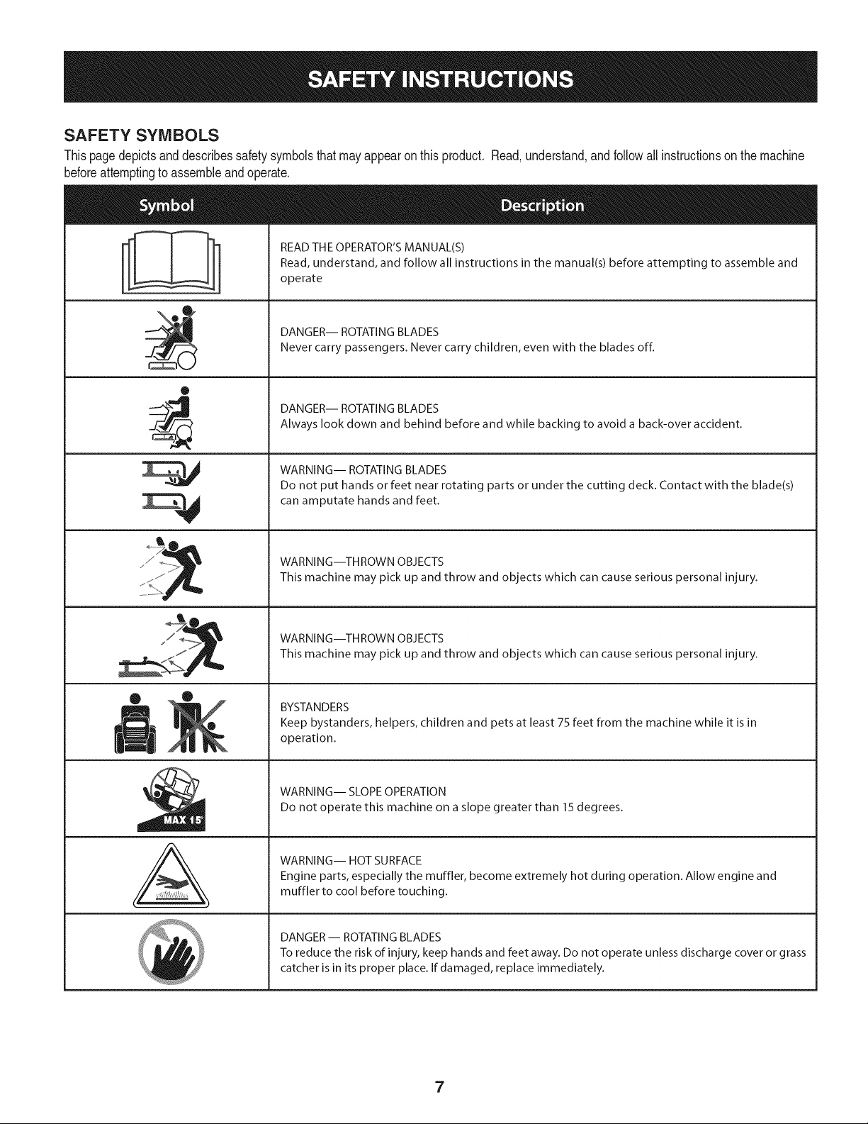
SAFETY SYMBOLS
Thispagedepictsand describessafety symbolsthatmayappearonthis product. Read,understand,and follow all instructionson the machine
beforeattemptingto assembleandoperate.
0
A
READ THE OPERATOR'S MANUAL(S)
Read, understand, and follow all instructions in the manual(s) before attempting to assemble and
operate
DANGER-- ROTATING BLADES
Never carry passengers. Never carry children, even with the blades off.
DANGER-- ROTATING BLADES
Always look down and behind before and while backing to avoid a back-over accident.
WARNING-- ROTATING BLADES
Do not put hands or feet near rotating parts or under the cutting deck. Contact with the blade(s)
can amputate hands and feet.
WARNING--THROWN OBJECTS
This machine may pick up and throw and objects which can cause serious personal injury.
WARNING--THROWN OBJECTS
This machine may pick up and throw and objects which can cause serious personal injury.
BYSTANDERS
Keep bystanders, helpers, children and pets at least 75 feet from the machine while it is in
operation.
WARNING-- SLOPE OPERATION
Do not operate this machine on a slope greater than 15 degrees.
WARNING-- HOT SURFACE
Engine parts, especially the muffler, become extremely hot during operation. Allow engine and
muffler to cool before touching.
DANGER-- ROTATING BLADES
To reduce the risk of injury, keep hands and feet away. Do not operate unless discharge cover or grass
catcher is in its proper place. If damaged, replace immediately.
7
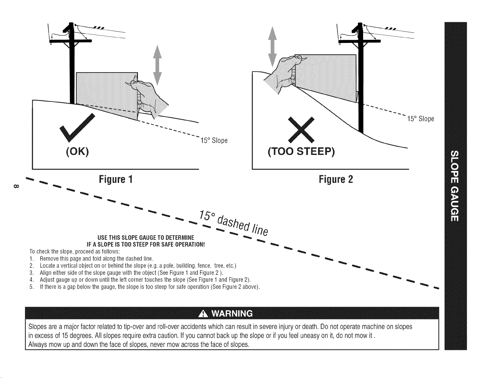
(OK)
15° Slope
X
(TOO STEEP)
15° Slope
'_. _ Figure1
USETHISSLOPEGAUGETODETERMINE
IFA SLOPEIS TOOSTEEPFORSAFEOPERATION!
To checkthe slope,proceedas follows:
1. Removethis pageandfold along the dashedline.
2. Locatea verticalobject onor behindthe slope (e.g. a pole, building,fence, tree, etc.)
3. Align eitherside of the slope gaugewith the object (See Figure1 and Figure2 ).
4. Adjust gaugeupor down until the left cornertouchesthe slope (SeeFigure1 and Figure2).
5.
15°
dashed line
If there is agap belowthe gauge,the slope is too steepfor safeoperation(SeeFigure2 above).
Figure2
Slopes are a majorfactor related to tip-over and roll-over accidents which can result in severe injury or death. Do not operatemachine on slopes
in excess of 15 degrees. All slopes require extra caution. If you cannot back up the slope or if you feel uneasy on it, do not mow it.
Always mow up and down the face of slopes, never mow across the face of slopes.
IMPORTANT:Yourtractoris shippedwithmotoroil in theengine.
However,you MUSTcheckthe oil levelbeforeoperating.Referto the
Service& Maintenancesectionfor instructionson checkingtheoil
level.
Attaching the Battery Cables
CALIFORNIA PROPOSITION 65
Batteryposts,terminals,andrelatedaccessoriescontainleadand
leadcompounds,chemicalsknownto the Stateof Californiato
causecancerand reproductiveharm.Washhandsafter handling.
Whenattachingbatterycables,alwaysconnectthe POSITIVE(Red)
wireto its terminalfirst,followedby the NEGATIVE(Black)wire.
Forshippingreasons,bothbatterycablesonyourequipmenthave
beenleft disconnectedfrom the terminalsat the factory.Toconnect
the batterycables,proceedas follows:
NOTE:Thepositivebatteryterminalis markedPos. (+).The negative
batteryterminalis markedNeg.(i).
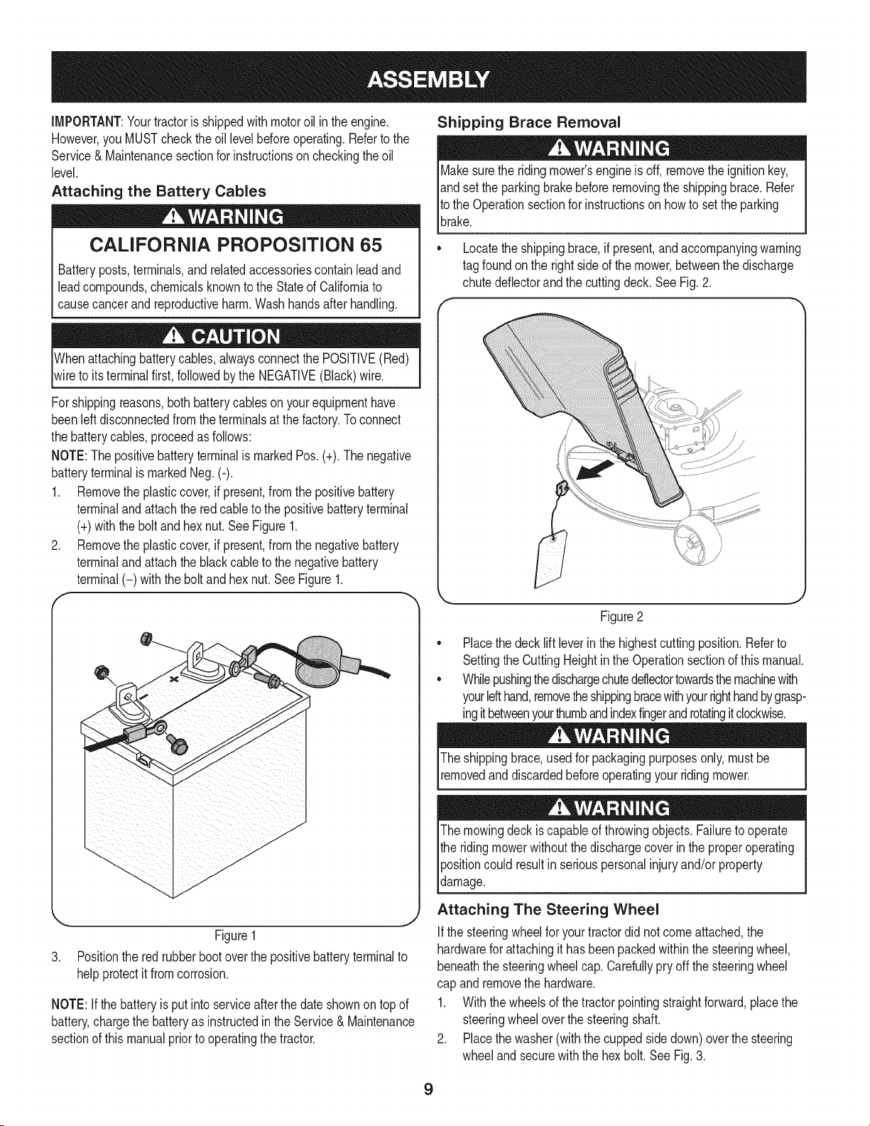
1. Removethe plasticcover,if present,fromthe positivebattery
terminaland attachthe redcableto the positivebatteryterminal
(+)withthe bolt andhexnut.See Figure1.
2. Removethe plasticcover,if present,fromthe negativebattery
terminaland attachthe blackcableto the negativebattery
terminal(-) withthe bolt andhex nut.SeeFigure1.
f
J
Figure1
3. Positionthe red rubberbootoverthe positivebatteryterminalto
helpprotectit fromcorrosion.
NOTE:If thebatteryis put into serviceafter the dateshownon topof
battery,chargethe batteryas instructedinthe Service & Maintenance
sectionof this manualprior to operatingthe tractor.
Shipping Brace Removal
Makesurethe ridingmower'sengineis off, removetheignitionkey,
andset the parkingbrakebeforeremovingthe shippingbrace. Refer
Itothe Operationsectionfor instructionson howto setthe parking
lbrake.
• Locatethe shippingbrace,if present,andaccompanyingwarning
tag foundonthe rightsideof the mower,betweenthe discharge
chutedeflectorand the cuttingdeck. See Fig. 2.
Figure2
Placethe deck lift leverinthe highestcuttingposition.Referto
SettingtheCuttingHeightin the Operationsectionof thismanual.
Whilepushingthedischargechuteddlectortowardsthemachinewith
yourlefthand,removetheshippingbracewithyourrighthandbygrasp-
ingitbetweenyourthumbandindexfingerandrotatingitclockwise.
The shippingbrace,usedfor packagingpurposesonly, mustbe
removedand discardedbeforeoperatingyour ridingmower.
The mowingdeck iscapableof throwingobjects.Failureto operate
the ridingmowerwithoutthe dischargecoverin the properoperating
Ipositioncould resultin seriouspersonalinjuryand/orproperty
ldamage.
Attaching The Steering Wheel
Ifthe steeringwheelfor yourtractordid notcomeattached,the
hardwarefor attachingit has beenpackedwithinthe steeringwheel,
beneaththe steeringwheelcap.Carefullypry off the steeringwheel
cap and removethe hardware.
1. Withthe wheelsof the tractorpointingstraightforward,placethe
steeringwheeloverthe steeringshaft.
2. Placethe washer(withthe cuppedsidedown)overthe steering
wheeland securewiththe hex bolt.SeeFig.3.
9
f
\
Figure3
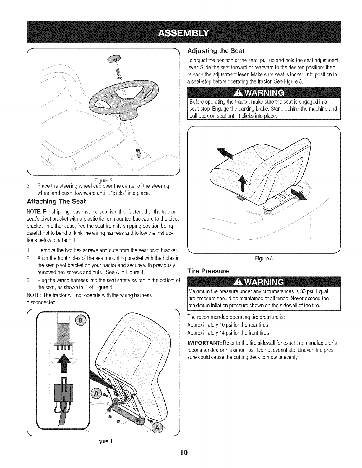
3. Placethe steeringwheelcap overthe center of the steering
wheeland pushdownwarduntilit "clicks"intoplace.
Attaching The Seat
NOTE:Forshippingreasons,the seatis eitherfastenedtothe tractor
seat'spivotbracketwitha plastictie, or mountedbackwardto the pivot
bracket.Ineithercase,free the seatfromits shippingpositionbeing
carefulnotto bendor kink the wiringharnessandfollowtheinstruc-
tionsbelowto attach it.
1. Removethetwo hexscrewsandnuts fromthe seatpivot bracket.
2. Alignthefrontholesof the seat mountingbracketwith the holesin
the seat pivotbracketon yourtractorand securewith previously
removedhex screwsandnuts. See A in Figure4.
3. Plugthe wiringharnessintothe seat safetyswitchinthe bottomof
the seat,as shownin Bof Figure4.
NOTE:The tractorwill not operatewiththe wiringharness
disconnected.
," -)
Adjusting the Seat
Toadjust the positionof the seat,pull up and hold the seatadjustment
lever.Slide the seatforwardor rearwardto thedesiredposition;then
releasethe adjustmentlever.Makesure seatis lockedintopositionin
a seat-stopbeforeoperatingthe tractor.See Figure5.
Beforeoperatingthe tractor,makesurethe seatis engagedin a
seat-stop.Engagethe parkingbrake.Standbehindthe machineand
pull backon seatuntil it clicks intoplace.
Figure5
Tire Pressure
Maximumtire pressureunderany circumstancesis 30 psi.Equal
tire pressureshouldbe maintainedat all times.Neverexceedthe
_maxmum nfat onpressureshownonthe s dewa of thet re.
The recommendedoperatingtire pressureis:
Approximately10psi forthe reartires
Approximately14psi forthe fronttires
iMPORTANT: Referto the tire sidewallfor exacttire manufacturer's
recommendedor maximumpsi. Donot overinfiate.Uneventirepres-
surecouldcausethe cuttingdeckto mowunevenly.
Figure4
10
J
C
D
E
G
F
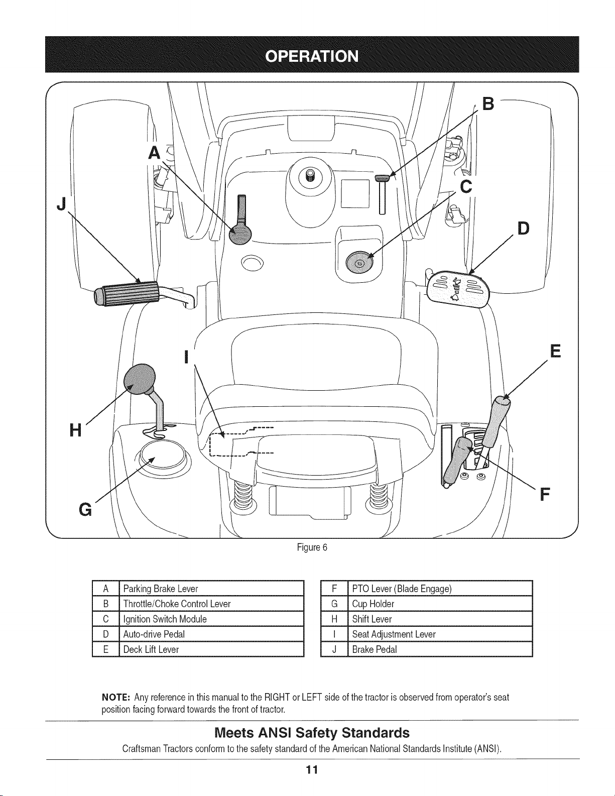
Figure6
A ParkingBrakeLever
B Throttle/ChokeControlLever
C IgnitionSwitchModule
D Auto-drivePedal
E DeckLift Lever
F PTOLever(BladeEngage)
G Cup Holder
H Shift Lever
I SeatAdjustmentLever
J BrakePedal
NOTE: Any referencein this manualto the RIGHTorLEFTsideof the tractoris observedfromoperator'sseat
positionfacingforwardtowardsthe frontof tractor.
Meets ANS! Safety Standards
CraftsmanTractorsconformto the safetystandardof theAmericanNationalStandardsInstitute(ANSI).
11
PARKING BRAKE LEVER
To set the parkingbrake: Fullydepressthe brakepedal.Movethe
parkingbrakeleverintothe parkingbrakeposition.Releasethe brake
pedalto allowthe parkingbraketo engage.
To releasethe parking brake: Depressthe brakepedalandthe park-
ingbrakeleverwill moveoutof the parkingbrakepositionon its own.
The parkingbrakewill then be released.Releasethe brakepedal.
NOTE: The parkingbrakemustbe setif the operatorleavesthe seat
withtheengine runningor the enginewill automaticallyshutoff.
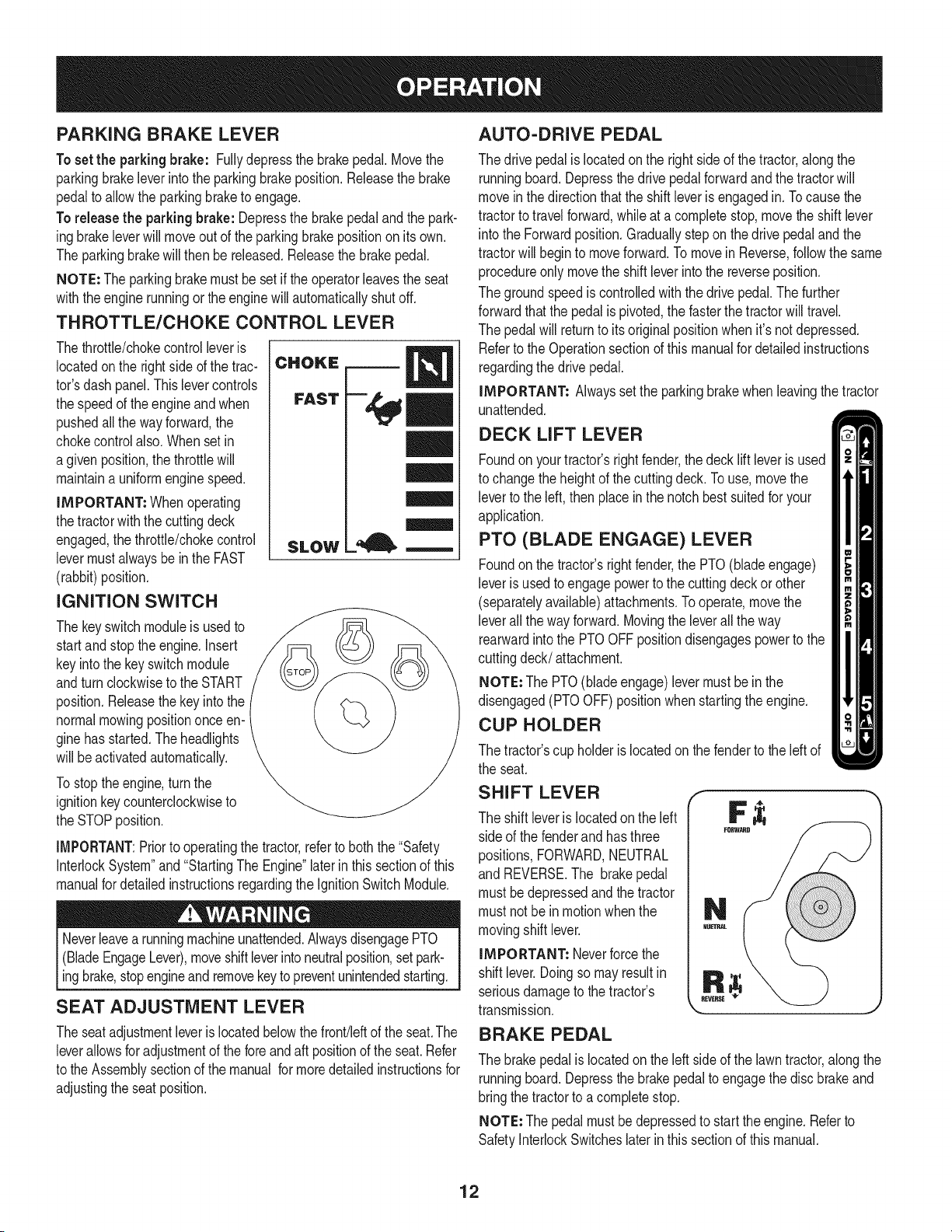
THROTTLE/CHOKE CONTROL LEVER
Thethrottle/chokecontrolleveris
locatedonthe rightside of the trac-
tor'sdash panel.Thislevercontrols
the speedof theengineandwhen
pushedall the wayforward,the
chokecontrolalso.Whensetin
agiven position,the throttlewill
maintaina uniformenginespeed.
iMPORTANT: Whenoperating
thetractorwiththe cuttingdeck
engaged,the throttle/chokecontrol
levermustalwaysbe inthe FAST
(rabbit)position.
IGNITION SWITCH
The keyswitch moduleis usedto
startand stopthe engine.Insert
keyintothe keyswitchmodule
andturnclockwiseto the START
position.Releasethekey into the
normalmowingpositiononceen-
ginehas started.The headlights
will be activatedautomatically.
Tostop theengine,turnthe
ignitionkeycounterclockwiseto
the STOPposition.
CHOKE
FAST
SLOW
-tell
IMPORTANT:Priorto operatingthe tractor,referto boththe "Safety
InterlockSystem"and"StartingThe Engine"laterin this sectionof this
manualfor detailedinstructionsregardingthe IgnitionSwitchModule.
Neverleavea runningmachineunattended.AlwaysdisengagePTO
(BladeEngageLever),moveshiftleverinto neutralposition,setpark-
ingbrake,stopengineand removekey topreventunintendedstarting.
SEAT ADJUSTMENT LEVER
Theseat adjustmentleveris locatedbelowthe front!leftof the seat.The
leverallowsfor adjustmentof the foreandaft positionof the seat.Refer
to the Assemblysectionof the manual formoredetailedinstructionsfor
adjustingthe seatposition.
AUTO-DRIVE PEDAL
The drivepedalis locatedonthe right sideof the tractor,alongthe
runningboard.Depressthe drivepedalforwardandthe tractorwill
moveinthe directionthatthe shiftleveris engagedin. Tocausethe
tractorto travelforward,whileat a completestop,movethe shift lever
into the Forwardposition.Graduallystep on the drivepedal and the
tractorwill beginto moveforward.To movein Reverse,followthe same
procedureonly movethe shiftleverintothe reverseposition.
The groundspeedis controlledwith the drivepedal.Thefurther
forwardthatthe pedalis pivoted,the fasterthe tractorwill travel.
The pedalwill returnto itsoriginal positionwhen it's notdepressed.
Referto the Operationsectionof thismanualfor detailedinstructions
regardingthe drive pedal.
IMPORTANT: Alwayssetthe parkingbrakewhenleavingthe tractor
unattended.
DECK LIFT LEVER
Foundonyourtractor'srightfender,the decklift leveris used
to changethe heightof thecuttingdeck.To use, movethe
leverto the left, thenplace inthe notchbestsuitedfor your
application.
PTO (BLADE ENGAGE) LEVER
Foundonthe tractor'srightfender,the PTO(blade engage)
leveris usedto engagepowerto the cuttingdeck or other
(separatelyavailable)attachments.Tooperate,movethe
leverall thewayforward.Movingthe leverall the way
rearwardinto the PTOOFFpositiondisengagespowerto the
cuttingdeck/attachment.
NOTE: The PTO(blade engage)levermustbein the
disengaged(PTOOFF)positionwhenstartingtheengine.
CUP HOLDER
The tractor'scup holderis locatedon the fenderto the left of
the seat.
SHIFT LEVER _"
The shift leveris locatedon the left
side of the fenderand hasthree
positions,FORWARD,NEUTRAL
and REVERSE.The brakepedal
must be depressedandthe tractor
must notbe in motionwhenthe
movingshift lever.
IMPORTANT: Neverforcethe
shift lever.Doingso mayresultin
seriousdamageto thetractor's
transmission.
BRAKE PEDAL
The brakepedalis locatedon the left sideof the lawntractor,alongthe
runningboard.Depressthe brakepedalto engagethe discbrakeand
bringthe tractorto acompletestop.
NOTE: Thepedal mustbedepressedto startthe engine.Referto
SafetyInterlockSwitcheslaterin this sectionof thismanual.
12
GAS AND OIL FILL-UP
0il
IMPORTANT: Yourtractorisshippedwith motoroil in the engine.
However,you MUSTcheckthe oil levelbeforeoperating.Be careful
not tooverfill.
For instructionsonhowto checkthe engineoil, referto CheckingThe
EngineOilin the ServiceandMaintenancesectionof this manual.
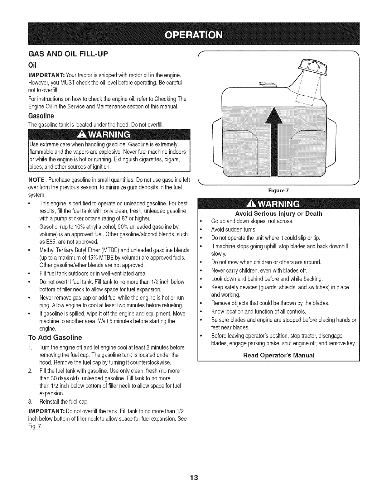
Gasoline
Thegasolinetank islocatedunderthe hood.Do notoverfill.
Useextremecarewhenhandlinggasoline.Gasolineis extremely
flammableandthe vaporsare explosive.Neverfuel machineindoors
orwhile theengineishotor running.Extinguishcigarettes,cigars,
p pes,andothersourcesof gn t on.
NOTE : Purchasegasolineinsmall quantities.Do notuse gasolineleft
overfrom the previousseason,to minimizegumdepositsinthe fuel
system.
• Thisengineiscertifiedto operateonunleadedgasoline.For best
results,fill thefuel tankwithonlyclean, fresh,unleadedgasoline
witha pumpstickeroctaneratingof 87or higher.
• Gasohol(upto 10%ethylalcohol,90% unleadedgasolineby
volume)is an approvedfuel.Othergasoline/alcoholblends,such
as E85,arenot approved.
• MethylTertiaryButylEther(MTBE)andunleadedgasolineblends
(upto a maximumof 15%MTBEby volume)areapprovedfuels.
Othergasoline/etherblendsarenotapproved.
• Fill fueltankoutdoorsor in well-ventilatedarea.
• Do notoverfillfuel tank. Filltankto no morethan 1/2inchbelow
bottomof fillerneck to allowspacefor fuel expansion.
• Neverremovegas cap oradd fuel whilethe engineishot or run-
ning.Allowengineto cool at leasttwo minutesbeforerefueling.
• If gasolineisspilled,wipe itoff the engineandequipment.Move
machineto anotherarea.Wait5 minutesbeforestartingthe
engine.
To Add Gasoline
1. Turnthe engineoff andlet enginecoolat least2 minutesbefore
removingthe fuelcap. Thegasolinetank islocatedunderthe
hood.Removethefuel cap byturningitcounterclockwise.
2. Fill thefuel tankwith gasoline.Useonly clean,fresh(nomore
than30 daysold), unleadedgasoline.Filltankto no more
than 1/2 inchbelowbottomof filler neckto allowspacefor fuel
expansion.
3. Reinstallthe fuelcap.
IMPORTANT: Donot overfillthe tank.Filltankto nomorethan 1/2
inchbelowbottomof fillerneck to allowspace forfuel expansion.See
Fig.7.
Figure7
Avoid Serious injury or Death
• Go upanddownslopes,notacross.
• Avoidsuddenturns.
• Donot operatethe unitwhereitcould slipor tip.
• If machinestopsgoinguphill,stopbladesandbackdownhill
slowly.
• Donot mowwhenchildrenorothersarearound.
• Nevercarry children,evenwithbladesoff.
• Lookdownandbehind beforeand whilebacking.
• Keepsafetydevices(guards,shields,and switches)in place
andworking.
• Removeobjectsthatcould be thrownby the blades.
• Knowlocationand functionof all controls.
• Be surebladesand enginearestoppedbeforeplacinghandsor
feetnear blades.
• Beforeleavingoperator'sposition,stoptractor,disengage
blades,engageparkingbrake,shutengineoff, and removekey.
Read Operator's Manual
13
SAFETY iNTERLOCK SYSTEM
The safetyinterlocksystemisdesignedfor safeoperationof thetrac-
tor.Ifthis systemshouldevermalfunction,do notoperatethetractor,
Immediatelycontact1-800-4-MY-HOMEto havethe systemserviced.
• The safetyinterlocksystempreventstheenginefromstarting
unlessthe parkingbrakeis engagedandthe PTO(BladeEngage)
leveris inthe disengaged(OFF)position.
• The safetyinterlocksystemwill automaticallyshut off theengineif
theoperatorleavesthe seatbeforeengagingthe parkingbrake.
• The safetyinterlocksystemwill automaticallyshut off theengine
ifthe operatorleavesthetractor'sseat with the PTO(Blade
Engage)leverengaged,regardlessof whetherthe parkingbrake
is engaged.
• Theenginewill automaticallyshutoff if the PTO(BladeEngage)
leveris movedintothe engaged(ON)positionwith the shift lever
in Reverse.
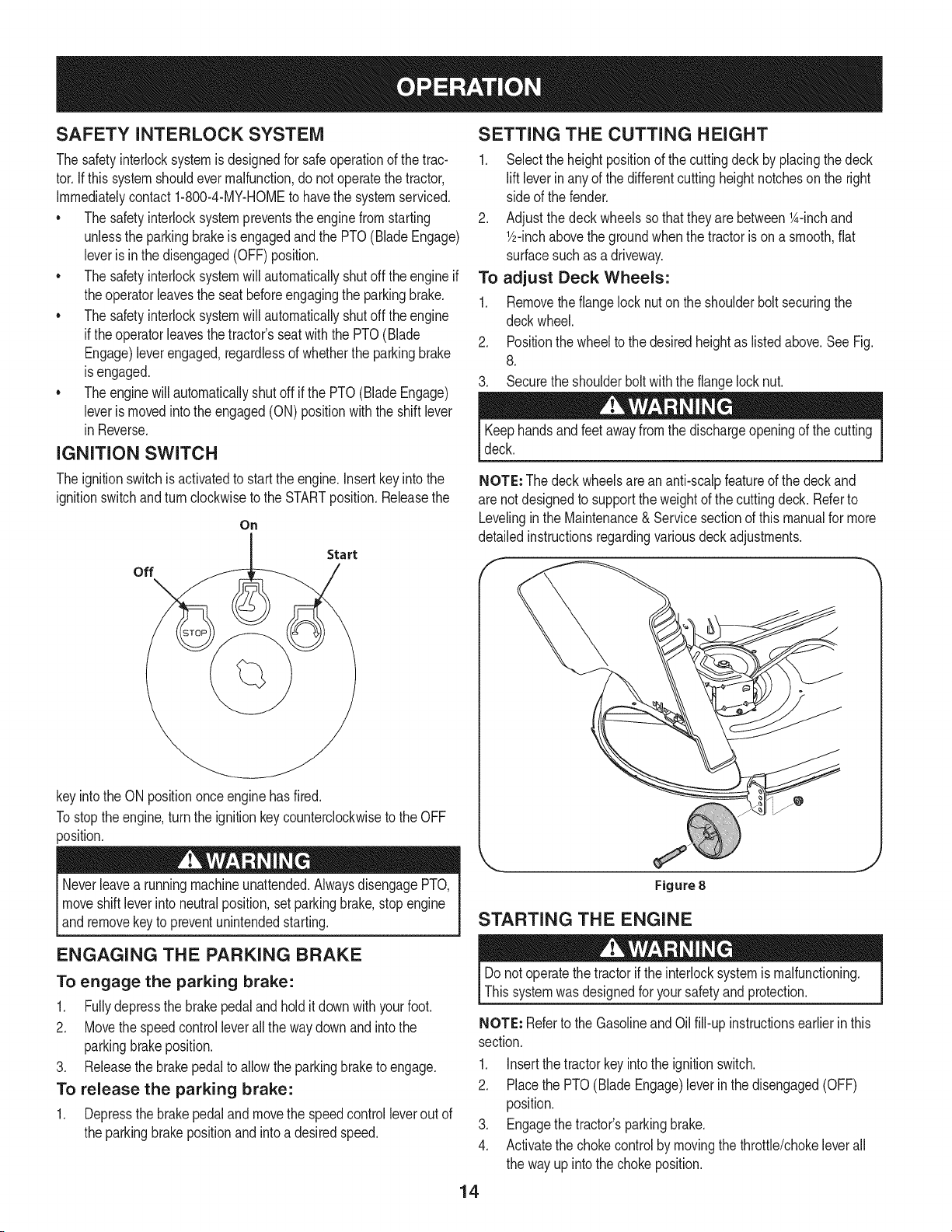
IGNITION SWITCH
The ignitionswitchis activatedto startthe engine,insert keyinto the
ignitionswitchandturnclockwiseto the STARTposition.Releasethe
On
Start
off
keyintothe ON positiononceenginehasfired.
Tostop theengine,turnthe ignitionkey counterclockwiseto the OFF
position.
Neverleavea runningmachineunattended.AlwaysdisengagePTO,
moveshift leverintoneutralposition,set parkingbrake,stop engine
_andremovekey to preventunntendedstartng.
ENGAGING THE PARKING BRAKE
To engage the parking brake:
1. Fullydepressthe brakepedalandholdit down withyourfoot.
2. Movethe speedcontrolleverallthe way downandintothe
parkingbrakeposition.
3. Releasethe brakepedalto allowthe parkingbraketo engage.
To release the parking brake:
1. Depressthe brakepedalandmovethe speedcontrolleverout of
the parkingbrakepositionandintoa desiredspeed.
SETTING THE CUTTING HEIGHT
1. Selectthe heightpositionof the cuttingdeckby placingthe deck
lift leverin anyof the differentcuttingheightnotchesonthe right
side of the fender.
2. Adjustthe deck wheelssothat they are between1A-inchand
1/2-inchabovethe groundwhenthe tractoris ona smooth,fiat
surfacesuch as adriveway.
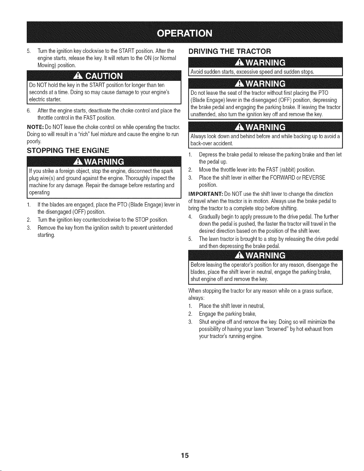
To adjust Deck Wheels:
1. Removethe flangelocknuton the shoulderbolt securingthe
deckwheel.
2. Positionthe wheelto thedesiredheightas listedabove.See Fig.
8.
3. Securethe shoulderboltwith the flangelock nut.
Keephandsandfeet awayfrom the dischargeopeningof the cutting
deck.
NOTE: Thedeck wheelsare an anti-scalpfeatureof the deckand
are notdesignedto supportthe weightof the cuttingdeck. Referto
Levelinginthe Maintenance& Servicesectionof thismanualfor more
detailedinstructionsregardingvariousdeck adjustments.
Figure8
STARTING THE ENGINE
Donot operatethe tractorif the interlocksystemis malfunctioning.
Thissystemwasdesignedfor yoursafetyand protection.
NOTE: Referto the Gasolineand Oil fill-up instructionsearlierinthis
section.
1. Insertthe tractorkeyintothe ignitionswitch.
2. Placethe PTO(Blade Engage)leverinthe disengaged(OFF)
position.
3. Engagethe tractor'sparkingbrake.
4. Activatethe chokecontrolby movingthethrottle/chokeleverall
the way up intothechokeposition.
14
5. Turnthe ignitionkeyclockwiseto the STARTposition.Afterthe
enginestarts,releasethe key.It will returnto the ON (or Normal
Mowing)position.
Do NOThold the keyin the STARTpositionfor longerthan ten
secondsat a time.Doingso maycause damageto yourengine's
electricstarter.
6. Aftertheenginestarts,deactivatethe chokecontroland placethe
throttlecontrolin the FASTposition.
NOTE: Do NOTleavethe chokecontrolon whileoperatingthetractor.
Doingso will resultin a "rich" fuelmixtureandcausethe engineto run
poorly.
STOPPING THE ENGINE
Ifyou strikea foreignobject,stopthe engine,disconnectthe spark
plugwire(s)andgroundagainstthe engine.Thoroughlyinspectthe
machinefor anydamage.Repairthe damagebeforerestartingand
operating
.
3.
If the bladesare engaged,placethe PTO(Blade Engage)leverin
the disengaged(OFF)position.
Turnthe ignitionkeycounterclockwiseto the STOPposition.
Removethekey from the ignitionswitchto preventunintended
starting.
DRIVING THE TRACTOR
Avoidsuddenstarts,excessivespeedandsuddenstops.
Donot leavethe seat of the tractorwithoutfirst placingthe PTO
(BladeEngage)leverin thedisengaged(OFF)position,depressing
the brakepedalandengagingthe parkingbrake.If leavingthe tractor
unattended,also turnthe ignitionkeyoff and removethekey.
Alwayslook downandbehindbeforeandwhile backingup to avoida
back-overaccident.
1. Depressthe brakepedalto releasethe parkingbrakeand thenlet
the pedal up.
2. Movethe throttleleverintothe FAST(rabbit)position.
3. Placethe shift leverineitherthe FORWARDor REVERSE
position.
iMPORTANT: Do NOTuse theshift leverto changethe direction
of travel whenthetractoris inmotion.Alwaysusethe brakepedalto
bringthe tractorto a completestopbeforeshifting.
4. Graduallybeginto apply pressureto the drivepedal.Thefurther
downthe pedalispushed,the fasterthe tractorwilltravelinthe
desireddirectionbasedon the positionof the shift lever.
5. The lawntractorisbroughtto a stopby releasingthedrive pedal
andthen depressingthe brakepedal.
Beforeleavingthe operator'spositionfor any reason,disengagethe
blades,placethe shift leverinneutral,engagethe parkingbrake,
shutengineoff and removethe key.
Whenstoppingthetractorfor any reasonwhileon a grass surface,
always:
1. Placethe shift leverinneutral,
2. Engagethe parkingbrake,
3. Shutengineoffand removethe key.Doingso will minimizethe
possibilityof havingyour lawn"browned"by hot exhaustfrom
yourtractor'srunningengine.
15
DRiViNG ON SLOPES
Referto the SLOPEGAUGEin the SafetyInstructionssectionof the
manualto help determineslopeswhereyou mayoperatethistractor
safely.
Do notmowon inclineswitha slope inexcessof 15degrees(a rise
of approximately2-1/2feetevery 10feet). Thetractorcouldoverturn
[and causeserous njury.
• Mowupanddownslopes,NEVERacross.
Exerciseextremecautionwhenchangingdirectionon slopes.
Watchfor holes, ruts,bumps,rocks,or otherhiddenobjects.
Uneventerraincouldoverturnthe machine.Tallgrasscan hide
obstacles.
Avoidturnswhendrivingon a slope. If a turn mustbe made,turn
downthe slope.Turningupa slopegreatlyincreasesthe chance
of a roll over.
Avoidstoppingwhendrivingupa slope.Ifit isnecessaryto stop
whiledrivingupa slope,start upsmoothlyandcarefullyto reduce
the possibilityof flippingthetractoroverbackward.
ENGAGING THE BLADES
Engagingthe PTO(Blade Engage)transferspowerto thecuttingdeck
orother (separatelyavailable)attachments.Toengagethe blades,
proceedas follows:
1. Movethe throttle/chokecontrolleverto the FAST(rabbit)position.
2. Graspthe PTO(BladeEngage)leverand pivotit all the way
forwardintothe engaged(ON)position.
3. Keepthe throttleleverinthe FAST(rabbit)positionfor the most
efficientuseof the cuttingdeckor other(separatelyavailable)
attachments.
NOTE: The enginewill automaticallyshutoff ifthe PTOisengaged
withthe shiftleverinpositionfor reversetravelwiththe ignitionkeyin
the ONposition.
MULCHING
A mulchkit is availableas an attachment.Mulchingis a processof
recirculatinggrassclippingsrepeatedlybeneaththe cuttingdeck. The
ultra-fineclippingsare thenforcedback intothe lawnwheretheyact as
a naturalfertilizer.
A mulchkitcan be purchasedthroughthe retaillocationinwhichyou
purchasedthis tractor.For more information,simply contact Sears
at 1-800-4-MY-HOME®.
USING THE DECK LIFT LEVER
To raisethe cuttingdeck,movethe decklift leverto the left,then place
itin the notchbestsuitedfor yourapplication.Referto SettingThe
CuttingHeightearlier inthis section.
MOWING
To helpavoidbladecontactora thrownobjectinjury,keepbystand-
ers,helpers,childrenand petsat least75feetfromthe machine
whileit is in operation.Stopmachineif anyoneentersthe area.
The followinginformationwill behelpfulwhenusingthe cuttingdeck
withyourtractor:
Planyourmowingpatternto avoiddischargeof materialstoward
roads,sidewalks,bystandersand the like.Also,avoiddischarging
materialagainstawall orobstructionwhichmaycausedischarged
materialto ricochetbacktowardthe operator.
• Donot mowat highgroundspeed,especiallyif a mulchkit or
grasscollectoris installed.
• Forbestresultsit isrecommendedthatthe first twolaps be cut
withthe dischargethrowntowardsthe center.After the firsttwo
laps, reversethedirectionto throwthe dischargeto theoutside
for the balanceof cutting.Thiswill givea betterappearanceto the
lawn.
• Donot cutthe grass tooshort. Shortgrassinvitesweedgrowth
andyellowsquicklyin dry weather.
• Mowingshouldalwaysbedone with the engineat full throttle.
• Underheavierconditionsit maybe necessaryto go backoverthe
cut areaa secondtimeto get a cleancut.
• Do NOTattemptto mowheavybrushand weedsand extremely
tall grass.Yourtractorisdesignedto mowlawns,NOTclear
brush.
• Keepthe bladessharpand replacethe bladeswhenworn. Refer
to CuttingBladesinthe Servicesectionof thismanualfor proper
bladesharpeninginstructions.
HEADLIGHTS
• The lampsare ON wheneverthetractor'sengineis running.
• The lampsturn OFFwhenthe ignitionkeyismovedto the STOP
position.
16
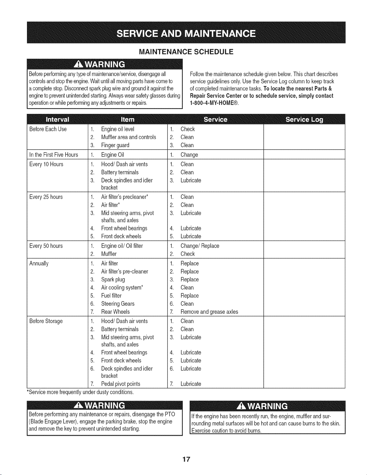
MAINTENANCE SCHEDULE
Beforeperforminganytypeof maintenance/service,disengageall
controlsand stoptheengine.Waituntilallmovingpartshavecometo
acompletestop.Disconnectsparkplugwireandgrounditagainstthe
engineto preventunintendedstarting.Alwayswearsafetyglassesduring
operationorwhileperforminganyadjustmentsor repairs.
Followthe maintenanceschedulegivenbelow.This chart describes
serviceguidelinesonly.Usethe ServiceLogcolumnto keeptrack
of completedmaintenancetasks.To locate the nearestParts&
Repair Service Centeror to scheduleservice,simplycontact
1-800-4-MY-HOME®.
BeforeEachUse 1.
2.
3.
In the FirstFive Hours 1.
Every10Hours 1.
2.
3.
Every25 hours 1.
2.
3.
4.
5.
Every50 hours 1.
2.
Annually 1.
2.
3.
4.
5.
6.
7.
BeforeStorage 1.
2.
3.
4.
5.
6.
7.
*Servicemorefrequentlyunder
Engineoil level
Mufflerareaandcontrols
Fingerguard
EngineOil
Hood/Dashair vents
Batteryterminals
Deckspindlesand idler
bracket
Air filter'sprecleaner*
Air filter*
Midsteeringarms,pivot
shafts,andaxles
Frontwheelbearings
Frontdeckwheels
Engineoil/Oil filter
Muffler
Air filter
Air filter'spre-cleaner
Sparkplug
Air coolingsystem*
Fuelfilter
SteeringGears
RearWheels
Hood/Dashair vents
Batteryterminals
Midsteeringarms,pivot
shafts,andaxles
Frontwheelbearings
Frontdeckwheels
Deckspindlesand idler
bracket
Pedalpivotpoints
dustyconditions.
1. Check
2. Clean
3. Clean
1. Change
1. Clean
2. Clean
3. Lubricate
1. Clean
2. Clean
3. Lubricate
4. Lubricate
5. Lubricate
1. Change/Replace
2. Check
1. Replace
2. Replace
3. Replace
4. Clean
5. Replace
6. Clean
7. Removeandgreaseaxles
1. Clean
2. Clean
3. Lubricate
4. Lubricate
5. Lubricate
6. Lubricate
7. Lubricate
Beforeperformingany maintenanceor repairs,disengagethe PTO
(BladeEngageLever),engagethe parkingbrake,stopthe engine
andremovethe keyto preventunintendedstarting.
If the enginehas beenrecentlyrun,the engine,mufflerand sur-
roundingmetalsurfaceswill behot and cancauseburnsto the skin.
Exercisecautionto avoidburns.
17
ENGINE MAINTENANCE
Checking the Engine Oil
Onlyuse highqualitydetergentoil ratedwithAPIserviceclassification
SF,SG,SH, or SJ. Selectthe oil's SAEviscositygradeaccordingto
theexpectedoperatingtemperature.Followthe chartbelow.
Althoughmulti-viscosityoils (5W20,10W30,etc.)improvestarting
incold weather,they will resultinincreasedoil consumptionwhen
usedabove32°E Checkyourengine oil level morefrequentlyto avoid
possibleenginedamagefromrunninglowon oil.
Colder_ 32°F _Warmer
5W20
Oil Viscosity Chart
_, J
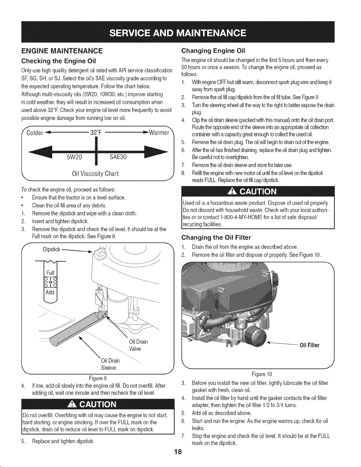
Tocheckthe engineoil, proceedas follows:
• Ensurethatthe tractoris ona levelsurface.
• Cleantheoil fill area of anydebris.
1. Removethe dipstickand wipe witha cleancloth.
2. Insertand tightendipstick.
3. Removethe dipstickand checkthe oil level.It shouldbe at the
Fullmark on the dipstick.See Figure9.
f
Dipstick
.
OilDrain
Valve
Oil Drain
Sleeve
._.,,, J
Figure 9
If low,addoil slowlyintothe engineoilfill. Do notoverfill.After
addingoil, wait oneminuteandthenrecheckthe oil level.
Do not overfill.Overfillingwith oil maycause theengineto notstart,
hardstarting,or engine smoking.If overthe FULLmarkon the
dipstick,drainoil to reduceoil levelto FULLmarkon dipstick.
5. Replaceand tighten dipstick.
Changing Engine Oil
The engineoil shouldbe changedinthe first 5 hoursand thenevery
50 hoursor once a season.To changethe engineoil, proceedas
follows:
1. WithengineOFFbutstillwarm,disconnectsparkplugwireandkeepit
awayfromsparkplug.
2. Removetheoil fillcap/dipstickfromtheoilfilltube.SeeFigure9.
3. Turnthesteeringwheelallthewaytotherighttobetterexposethedrain
plug.
4. Cliptheoildrainsleeve(packedwiththismanual)ontotheoildrainport.
Routetheoppositeendd thesleeveintoanappropriateoilcollection
containerwithacapacitygreatenoughto collecttheusedoil.
5. Removetheoil drainplug,Theoil willbegintodrainoutof theengine.
6. Aftertheoilhasfinisheddraining,replacetheoil drainplugandtighten.
Becarefulnottoovertighten.
7. Removetheoil drainsleeveandstoreforlateruse.
8. Rdilltheenginewithnewmotoroil untiltheoillevelonthedipstick
readsFULL.Replacetheoilfillcap/dipstick.
Usedoil is a hazardouswasteproduct.Disposeof usedoil properly.
Do notdiscardwithhouseholdwaste.Checkwithyour localauthori-
tiesoror contact 1-800-4-MY-HOMEfora listof safedisposal/
recyclingfacilities.
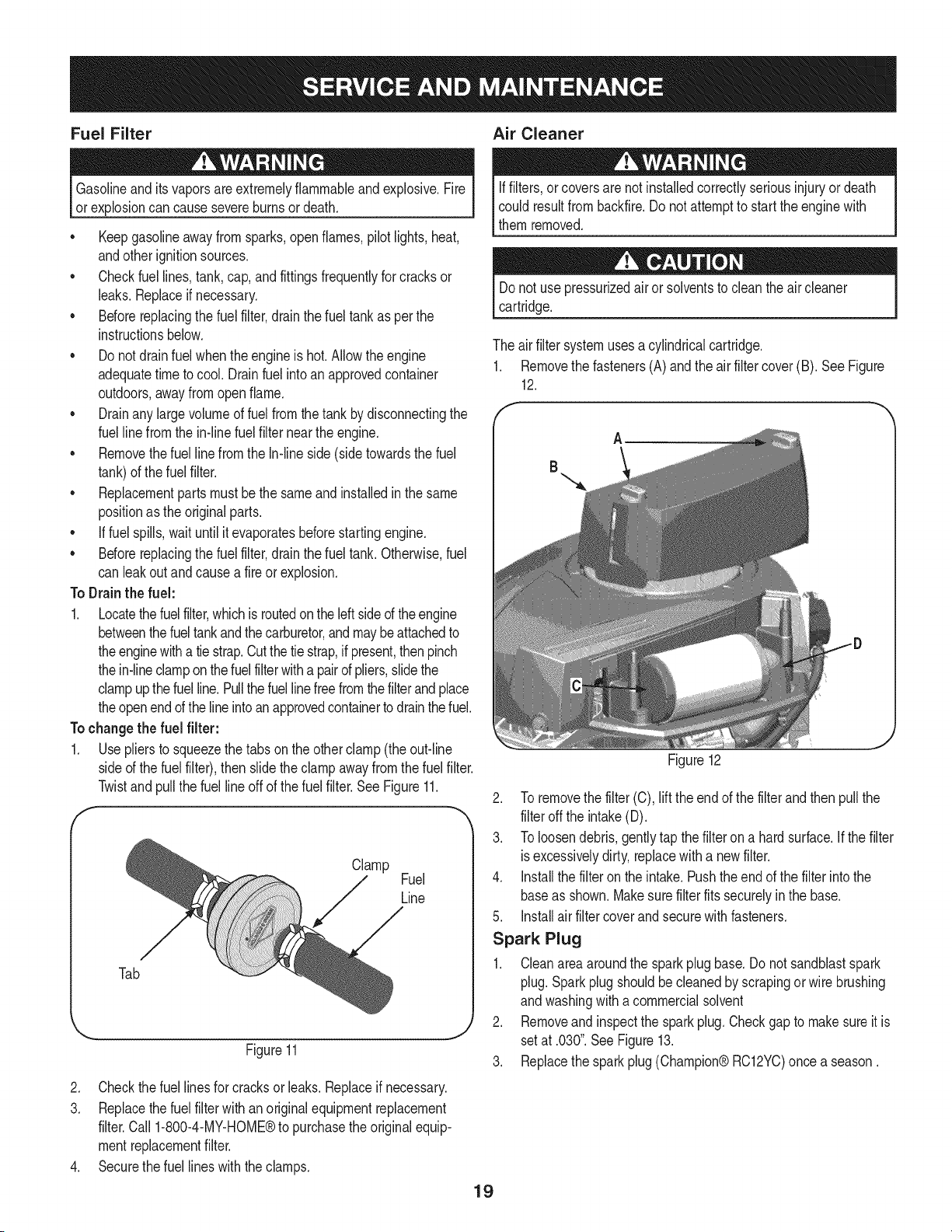
Changing the Oil Filter
1. Drainthe oil fromthe engineas describedabove.
2. Removethe oilfilteranddisposeof properly.See Figure10.
Figure10
3. Beforeyou installthe newoil filter, lightlylubricatethe oil filter
gasketwith fresh,cleanoil.
4. Installthe oilfilterby hand untilthe gasketcontactsthe oilfilter
adapter,then tightenthe oil filter 1/2to 3/4 turns.
5. Addoil as describedabove.
6. Startand run theengine.As theenginewarmsup,checkfor oil
leaks.
7. Stopthe engineand checktheoil level. It shouldbeat the FULL
markonthe dipstick.
18
Fuel Filter Air Cleaner
Gasolineandits vaporsare extremelyflammableand explosive.Fire
or explosioncan causesevereburnsor death.
• Keepgasolineawayfromsparks,openflames,pilotlights,heat,
andotherignitionsources.
• Checkfuellines,tank,cap, and fittingsfrequentlyfor cracksor
leaks.Replaceif necessary.
• Beforereplacingthe fuel filter,drain the fueltank as perthe
instructionsbelow.
• Do notdrainfuel whentheengineis hot.Allowtheengine
adequatetimeto cool. Drainfuel intoan approvedcontainer
outdoors,awayfromopenflame.
• Drainany largevolumeof fuelfromthe tank by disconnectingthe
fuelline from the in-linefuel filter neartheengine.
• Removethefuel linefrom the In-lineside (sidetowardsthe fuel
tank)of thefuel filter.
• Replacementpartsmustbethe same and installedin the same
positionas the originalparts.
• If fuelspills,waituntil it evaporatesbeforestartingengine.
• Beforereplacingthe fuel filter,drain the fueltank. Otherwise,fuel
can leakoutand causea fireor explosion.
To Drainthe fuel:
1. Locatethefuel filter,which isroutedonthe leftsideof theengine
betweenthefueltankand thecarburetor,andmaybe attachedto
theenginewitha tie strap.Cutthetie strap,if present,thenpinch
thein-lineclampon thefuelfilterwitha pairof pliers,slidethe
clampupthefuelline. Pullthe fuellinefreefromthefilterand place
theopenend of theline intoan approvedcontainerto drainthefuel.
Tochangethe fuel filter:
1. Usepliersto squeezethe tabs on the otherclamp (theout-line
sideof the fuel filter),thenslide theclamp awayfrom thefuel filter.
Twistandpull the fuelline off of the fuelfilter.See Figure11.
f
Clamp
Fuel
Line
Tab
J
Figure11
2. Checkthefuel linesfor cracksor leaks.Replaceif necessary.
3. Replacethefuel filterwith an originalequipmentreplacement
filter.Call 1-800-4-MY-HOME®to purchasethe originalequip-
mentreplacementfilter.
4. Securethe fuel lineswiththe clamps.
Iffilters,or coversare notinstalledcorrectlyseriousinjury or death
could resultfrom backfire.Do not attemptto startthe enginewith
themremoved.
Donot use pressurizedair orsolventsto cleanthe aircleaner
cartridge.
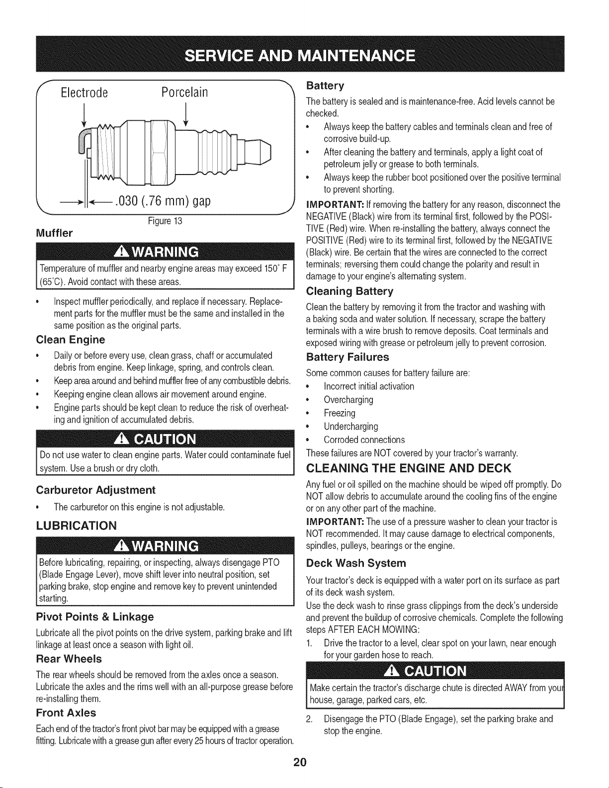
The air filter systemuses a cylindricalcartridge.
1. Removethe fasteners(A)andthe air filtercover (B). SeeFigure
12.
A
Figure12
2. To removethe filter (C), lift the endof the filterand thenpullthe
filteroff the intake(D).
3. To loosendebris,gentlytap thefilteron a hardsurface.If thefilter
isexcessivelydirty, replacewith a newfilter.
4. Installthe filteronthe intake.Pushthe endof the filterintothe
baseas shown.Makesurefilter fits securelyin the base.
5. Installair filtercover and securewith fasteners.
Spark Plug
1. Cleanareaaroundthe sparkplugbase.Donot sandblastspark
plug.Sparkplug shouldbecleanedby scrapingor wirebrushing
andwashingwith a commercialsolvent
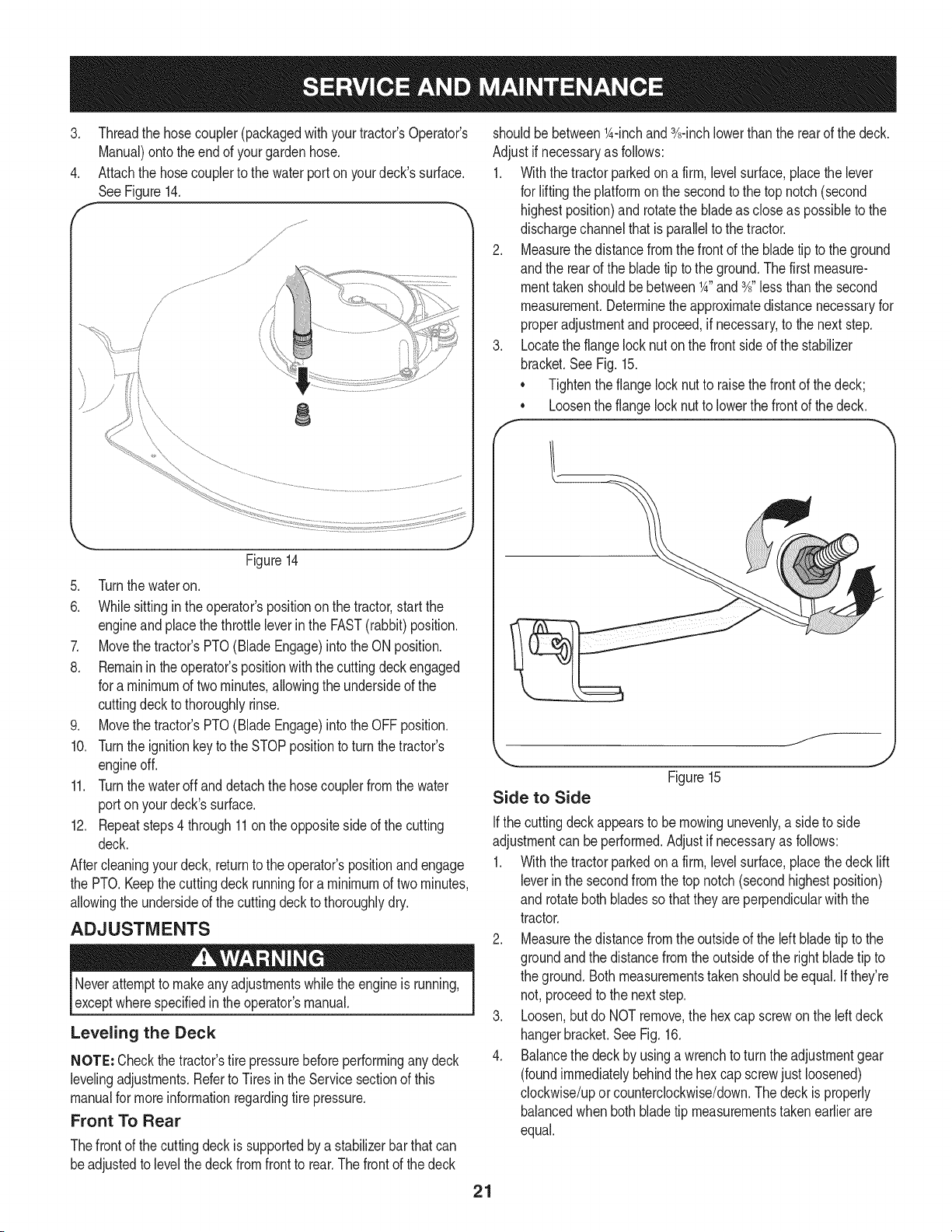
2. Removeandinspectthe sparkplug.Checkgapto make sureitis
setat .030".SeeFigure13.
3. Replacethe sparkplug(Champion®RC12YC)oncea season.
19
Electrode
Porcelain
Muffler
i. _ .030 (.76 mm) gap
Figure13
J
Temperatureof mufflerand nearbyengine areasmayexceed150° F
(65°0).Avoidcontact with theseareas.
• inspectmufflerperiodically,and replaceif necessary.Replace-
mentpartsfor the mufflermustbe the sameand installedin the
samepositionas the originalparts.
Clean Engine
• Dailyor beforeeveryuse,cleangrass,chaffor accumulated
debrisfromengine.Keeplinkage,spring,andcontrolsclean.
• Keepareaaroundandbehindmufflerfreeofanycombustibledebris.
• Keepingenginecleanallows air movementaroundengine.
• Enginepartsshouldbe keptcleanto reducethe riskof overheat-
ingandignitionof accumulateddebris.
Do notuse waterto cleanengineparts.Watercouldcontaminatefuel
system.Usea brushor dry cloth.
Carburetor Adjustment
• Thecarburetoronthis engineis not adjustable.
LUBRICATION
Beforelubricating,repairing,or inspecting,alwaysdisengagePTO
(BladeEngageLever),moveshift leverintoneutralposition,set
parkingbrake,stopengineand removekeyto preventunintended
starting.
Pivot Points & Linkage
Lubricateall thepivotpointson the drivesystem,parkingbrakeand lift
linkageat least oncea seasonwith light oil.
Rear Wheels
Battery
The batteryis sealedand is maintenance-free.Acidlevelscannotbe
checked.
• Alwayskeepthe batterycablesand terminalscleanandfree of
corrosivebuild-up.
• Aftercleaningthe batteryandterminals,applya lightcoatof
petroleumjelly orgreaseto bothterminals.
• Alwayskeepthe rubberbootpositionedoverthe positiveterminal
to preventshorting.
iMPORTANT: if removingthe batteryfor any reason,disconnectthe
NEGATIVE(Black) wirefromitsterminalfirst,followedby the POSi-
TIVE(Red)wire.Whenre-installingthe battery,alwaysconnectthe
POSITIVE(Red)wireto its terminalfirst,followedbythe NEGATIVE
(Black)wire.Becertainthat the wiresareconnectedto the correct
terminals;reversingthemcouldchangethe polarityandresult in
damageto your engine'salternatingsystem.
Cleaning Battery
Cleanthe batteryby removingit fromthe tractorand washingwith
a bakingsodaandwatersolution.Ifnecessary,scrape thebattery
terminalswitha wirebrushto removedeposits.Coatterminalsand
exposedwiringwith greaseor petroleumjelly to preventcorrosion.
Battery Failures
Somecommoncausesfor batteryfailureare:
incorrectinitialactivation
Overcharging
Freezing
Undercharging
Corrodedconnections
Thesefailuresare NOTcoveredby yourtractor'swarranty.
CLEANING THE ENGINE AND DECK
Any fuelor oil spilledon the machineshouldbe wipedoff promptly.Do
NOTallowdebristo accumulatearoundthe coolingfinsof theengine
or onany otherpart of the machine.
IMPORTANT: Theuse of a pressurewasherto cleanyourtractoris
NOTrecommended,it may causedamageto electricalcomponents,
spindles,pulleys,bearingsor the engine.
Deck Wash System
Yourtractor'sdeckis equippedwitha waterport on itssurfaceas part
of itsdeck washsystem.
Usethe deck washto rinsegrassclippingsfromthedeck'sunderside
and preventthe buildupof corrosivechemicals.Completethefollowing
stepsAFTEREACHMOWING:
1. Drivethetractorto a level,clear spot on yourlawn,nearenough
for yourgardenhoseto reach.
The rearwheelsshouldbe removedfrom the axlesoncea season.
Lubricatethe axlesandthe rimswell withanall-purposegreasebefore
re-installingthem.
Front Axles
Eachendof thetractor'sfrontpivotbarmaybeequippedwithagrease
fitting.Lubricatewitha greasegunafterevery25 hoursoftractoroperation.
Makecertain the tractor'sdischargechuteis directedAWAYfrom you
house,garage,parkedcars,etc.
2. Disengagethe PTO(Blade Engage),set the parkingbrakeand
stopthe engine.
2O
3. Threadthe hosecoupler(packagedwith yourtractor'sOperator's
Manual)ontothe endof yourgardenhose.
4. Attachthe hosecouplerto the waterport on yourdeck'ssurface.
SeeFigure14.
,/JJ"
/ ......:%:_................................................
8
Figure14
5. Turnthe wateron.
6. Whilesittingin theoperator'spositionon the tractor,startthe
engineandplacethe throttleleverinthe FAST(rabbit)position.
7. Movethe tractor'sPTO(BladeEngage)intothe ONposition.
8. Remaininthe operator'spositionwiththecuttingdeckengaged
for a minimumof two minutes,allowingthe undersideof the
cuttingdeckto thoroughlyrinse.
9. Movethe tractor'sPTO(BladeEngage)intothe OFFposition.
10. Turnthe ignitionkeyto the STOPpositionto turnthe tractor's
engineoff.
11. Turnthe wateroff and detachthe hosecouplerfrom the water
porton yourdeck'ssurface.
12. Repeatsteps4 through11on theoppositeside of the cutting
deck.
Aftercleaningyourdeck,returnto the operator'spositionand engage
the PTO.Keepthe cuttingdeckrunningfora minimumof twominutes,
allowingthe undersideof the cuttingdeckto thoroughlydry.
ADJUSTMENTS
Neverattemptto makeanyadjustmentswhilethe engine is running,
exceptwherespecifiedin theoperator'smanual.
Leveling the Deck
NOTE: Checkthe tractor'stire pressurebeforeperforminganydeck
levelingadjustments.Referto Tires in theServicesectionof this
manualfor moreinformationregardingtire pressure.
Front To Rear
Thefront of the cuttingdeckis supportedbya stabilizerbar thatcan
beadjustedto levelthe deckfromfrontto rear.Thefrontof the deck
shouldbe betweenl_-inchand3A-inchlowerthanthe rearof the deck.
Adjustif necessaryas follows:
1. Withthe tractorparkedona firm, levelsurface,placethe lever
for lifting the platformonthe secondto the top notch(second
highestposition)and rotatethe bladeas closeas possibleto the
dischargechannelthatis parallelto the tractor.
2. Measurethedistancefromthe front of the bladetip to theground
andthe rearof the bladetip tothe ground.Thefirst measure-
menttakenshouldbe between1_"and3A"less thanthe second
measurement.Determinetheapproximatedistancenecessaryfor
properadjustmentand proceed,if necessary,to the next step.
3. Locatethe flangelock nut on the frontsideof the stabilizer
bracket.See Fig. 15.
• Tightenthe flangelocknutto raisethe frontof the deck;
Loosentheflangelock nutto lowerthe frontof thedeck.
o
f__
Figure15
Side to Side
Ifthe cuttingdeckappearsto be mowingunevenly,a sideto side
adjustmentcan beperformed.Adjustif necessaryas follows:
1. Withthe tractorparkedona firm, levelsurface,placethe decklift
leverin the secondfromthe top notch(secondhighestposition)
and rotatebothbladesso thattheyare perpendicularwith the
tractor.
2. Measurethedistancefromthe outsideof the left bladetip to the
groundandthe distancefromthe outsideof the rightbladetip to
the ground.Bothmeasurementstakenshouldbe equal.Ifthey're
not,proceedto the next step.
3. Loosen,but do NOTremove,the hex capscrewon the left deck
hangerbracket.See Fig. 16.
4. Balancethe deckby usinga wrenchto turnthe adjustmentgear
(foundimmediatelybehindthe hex cap screwjustloosened)
clockwise/upor counterclockwise/down.Thedeck is properly
balancedwhenboth bladetip measurementstakenearlierare
equal.
21
HexCap Screw
Figure16
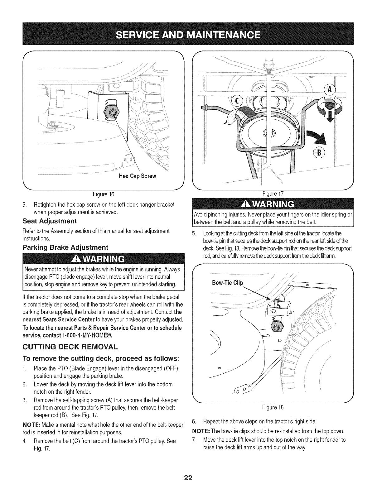
5. Retightenthe hexcap screwonthe left deckhangerbracket
when properadjustmentis achieved.
Seat Adjustment
Referto the Assemblysectionof thismanualfor seat adjustment
instructions.
Parking Brake Adjustment
Neverattemptto adjustthebrakeswhiletheengineis running.Always
disengagePTO(bladeengage)lever,moveshiftleverintoneutral
3osition,stopengineandremovekeyto preventunintendedstarting.
the tractordoesnot cometo a completestopwhenthe brakepedal
is completelydepressed,or if the tractor'srearwheelscan roll with the
parkingbrakeapplied,the brakeis in needof adjustment.Contactthe
nearest Sears Service Centerto haveyour brakesproperlyadjusted,
Tolocatethe nearest Parts& Repair Service Centeror to schedule
service,contact 1-800-4-MY-HOME®.
CUTTING DECK REMOVAL
To remove the cutting deck, proceed as follows:
1. Placethe PTO(BladeEngage)leverin the disengaged(OFF)
positionand engagetheparkingbrake.
2. Lowerthe deck by movingthe deck lift lever intothe bottom
notchon the rightfender.
3. Removethe self-tappingscrew(A)that securesthe belt-keeper
rodfromaroundthetractor's PTOpulley,then removethe belt
keeperrod (B). See Fig.17.
NOTE: Makea mentalnotewhatholethe otherend of the belt-keeper
rodis insertedin for reinstallationpurposes.
4. Removethe belt(C) fromaroundthe tractor'sPTOpulley.See
Fig. 17.
Figure17
Avoidpinchinginjuries.Neverplaceyourfingerson the idler springor
betweenthe beltand a pulleywhileremovingthe belt.
Lookingatthecuttingdeckfromtheleftsideofthetractor,locatethe
bow-tiepinthatsecuresthedecksupportrodon therearIdtsideofthe
deck.SeeFig.18.Removethebow-tiepinthatsecuresthedecksupport
rod,andcarefullyremovethedecksupportfromthedeckliftarm.
f
\
Figure18
6. Repeatthe abovestepson the tractor'srightside.
NOTE: Thebow-tieclips shouldbe re-installedfromthe topdown.
7. Movethedecklift leverintothe top notchon the rightfenderto
raisethedecklift arms up and out of the way.
22
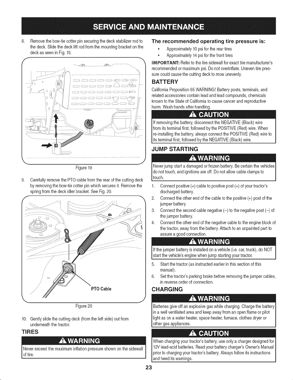
.
f
Removethebow-tiecotter pinsecuringthe deckstabilizerrodto
the deck.Slidethedecklift rod from the mountingbracketon the
deckas seenin Fig. 19.
h
..........._,,_2_...................... /_ ,/ .....................
L}}(- } C J_ C}_} /
f
The recommended operating tire pressure is:
Approximately10psifor the reartires
Approximately14psi for thefront tires
IMPORTANT: Referto the tire sidewallfor exacttire manufacturer's
recommendedor maximumpsi. Donot overinflate.Uneventirepres-
surecouldcausethe cuttingdeckto mowunevenly.
BATTERY
CaliforniaProposition65 WARNING!Batteryposts,terminals,and
relatedaccessoriescontainleadandleadcompounds,chemicals
knownto the Stateof Californiato causecancerand reproductive
harm.Washhandsafter handling.
If removingthe battery,disconnectthe NEGATIVE(Black)wire
fromitsterminalfirst,followedbythe POSITIVE(Red)wire. When
re-installingthe battery,alwaysconnectthe POSITIVE(Red)wireto
[ ts termna f rst,fo owedby the NEGATVE (Back) w re.
JUMP STARTING
.
Figure19
Carefullyremovethe PTOcablefromthe rearof the cuttingdeck
by removingthe bow-tiecotter pinwhich securesit. Removethe
springfromthe deckidlerbracket.SeeFig.20.
Neverjump starta damagedor frozenbattery.Be certainthe vehicles
do nottouch,andignitionsare off. Do notallowcable clampsto
touch.
1. Connectpositive(+)cableto positivepost (+)of yourtractor's
dischargedbattery.
2. Connectthe otherendof the cableto thepositive(+)post of the
jumperbattery.
3. Connectthe secondcable negative(-) to the negativepost(-) of
the jumperbattery.
4. Connectthe otherendof the negativecableto the engineblockof
the tractor,awayfromthe battery.Attachto anunpaintedpartto
assurea goodconnection.
Figure20
10. Gentlyslidethe cuttingdeck (from theleft side)out from
underneaththe tractor.
TIRES
Neverexceedthemaximuminflationpressureshownonthe sidewall
of tire.
Ifthejumper batteryis installedon a vehicle (i.e.car, truck), do NOT
start the vehicle'senginewhenjump startingyourtractor.
5. Startthe tractor(as instructedearlierin thissectionof this
manual).
6. Setthe tractor'sparkingbrakebeforeremovingthejumpercables,
inreverseorder of connection.
CHARGING
Batteriesgive off an explosivegas whilecharging.Chargethe battery
in a wellventilatedareaand keepawayfrom an openflame or pilot
light as ona waterheater,spaceheater,furnace,clothesdryeror
othergas appliances.
Whenchargingyourtractor'sbattery,useonlya chargerdesignedfor I
12Vlead-acidbatteries.Readyourbatterycharger_s Owner'sManualI
priorto chargingyourtractors battery.Alwaysfollowits instructions I
_andheed tswarnngs. J
23
Ifyour tractorhasnot been putinto usefor anextendedperiodof time, 4.
chargethe batteryas follows:
1. Setyour batterychargerto delivera maxof 10amperes.
Ifyour batterychargeris automatic,chargethe batteryuntilthe
chargerindicatesthatchargingis complete.Ifthe chargeris not
automatic,chargefor nofewerthaneight hours, f
FUSE
One20 AMPfuseis installedin yourtractor'swiring harnessto protect
thetractor'selectricalsystemfrom damagecausedby excessive
amperage.
Ifthe electricalsystemdoesnot function,or yourtractor'senginewill
notcrank,first checkto becertainthatthe fuse hasnot blown.It can
befoundat the rear of the unit, underneaththe fenderlocatedby the
battery.
Alwaysusea fuse with the sameamperagecapacityfor replacement.
CUTTING BLADES
Shutthe engineoffand removeignitionkeybeforeremovingthe
cuttingblade(s)for sharpeningor replacement.Protectyourhands
_byusng heavyg oves whengraspngthe bade.
Periodicallyinspectthe bladeand/or spindleforcracksor damage,
especiallyafter you'vestrucka foreignobject. Donot operatethe
machineuntil damagedcomponentsare replaced.
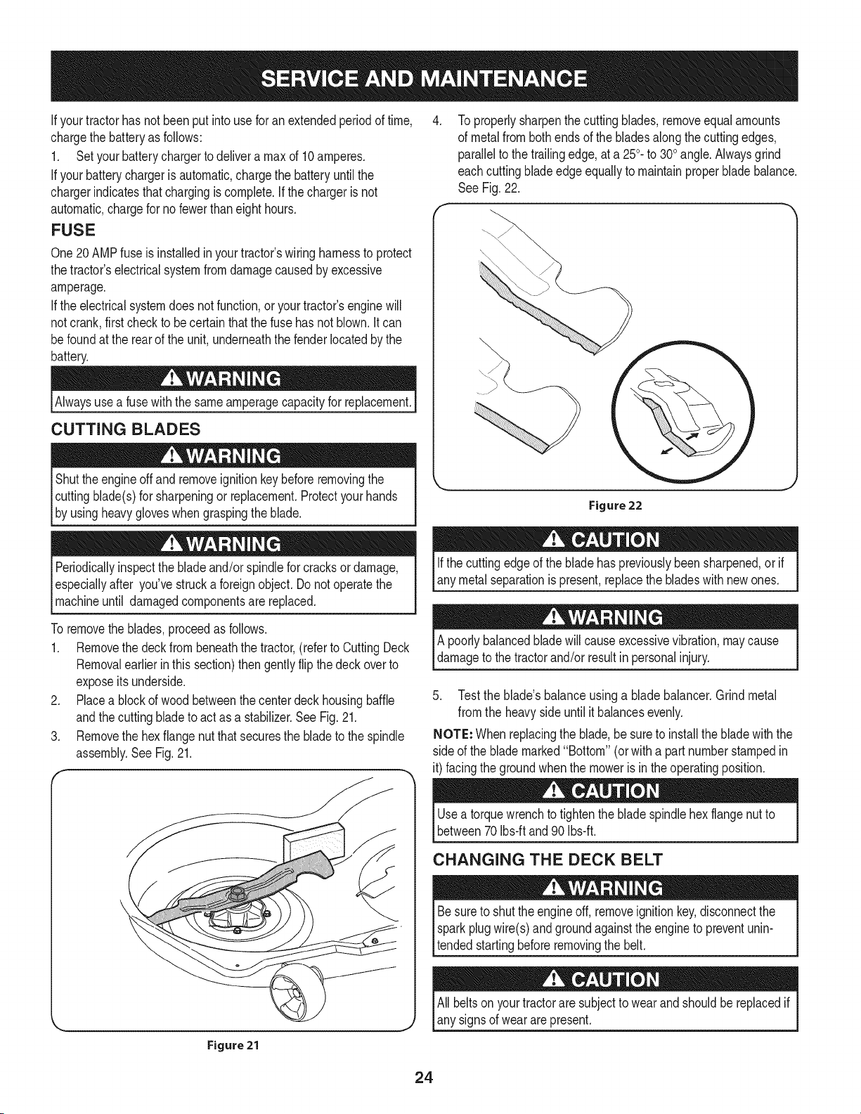
To properlysharpenthecutting blades,removeequalamounts
of metalfrombothendsof the bladesalongthe cuttingedges,
parallelto the trailingedge,at a 250.to 300angle.Alwaysgrind
eachcuttingbladeedge equallyto maintainproperbladebalance.
See Fig.22.
Figure22
Ifthe cuttingedgeof the bladehas previouslybeen sharpened,or if
any metalseparationis present,replacethe bladeswithnew ones.
To removetheblades,proceedas follows.
1. Removethe deck from beneaththe tractor,(referto CuttingDeck
Removalearlierinthis section)thengently flip thedeck overto
exposeitsunderside.
2. Placea blockof wood betweenthe centerdeck housingbaffle
andthe cuttingbladeto act asa stabilizer.See Fig. 21.
3. Removethe hexflangenutthatsecuresthe bladeto the spindle
assembly.SeeFig.21.
A poorlybalancedbladewill causeexcessivevibration,maycause
damageto thetractorand/or resultin personalinjury.
5. Testthe blade'sbalanceusinga bladebalancer.Grindmetal
fromthe heavyside untilit balancesevenly.
NOTE: Whenreplacingthe blade,be sureto installthe bladewith the
side of the blademarked"Bottom" (or witha partnumberstampedin
it) facingthe groundwhenthe moweris in the operatingposition.
Figure 21
Usea torquewrenchto tightenthe bladespindlehexflangenut to
between70 Ibs-ft and 90 Ibs-ft.
CHANGING THE DECK BELT
Besureto shut the engineoff, removeignitionkey,disconnectthe
sparkplugwire(s)and groundagainstthe engineto preventunin-
tendedstartingbeforeremovingthe belt.
All beltsonyourtractorare subjectto wearandshouldbereplacedif
any signsof wear arepresent.
24
iMPORTANT: The V-beltfoundon yourtractoris speciallydesigned
to engageanddisengagesafely.A substitute(non-OEM)V-beltcan
bedangerousby notdisengagingcompletely.Fora properworking
machine,useidenticalequipmentbeltsas listedin the partspagesof
thisOperator'sManual.
Tochangeor replacethedeckbelt onyourtractor,proceedas follows:
1. Removethedeck as instructedearlier in this section.
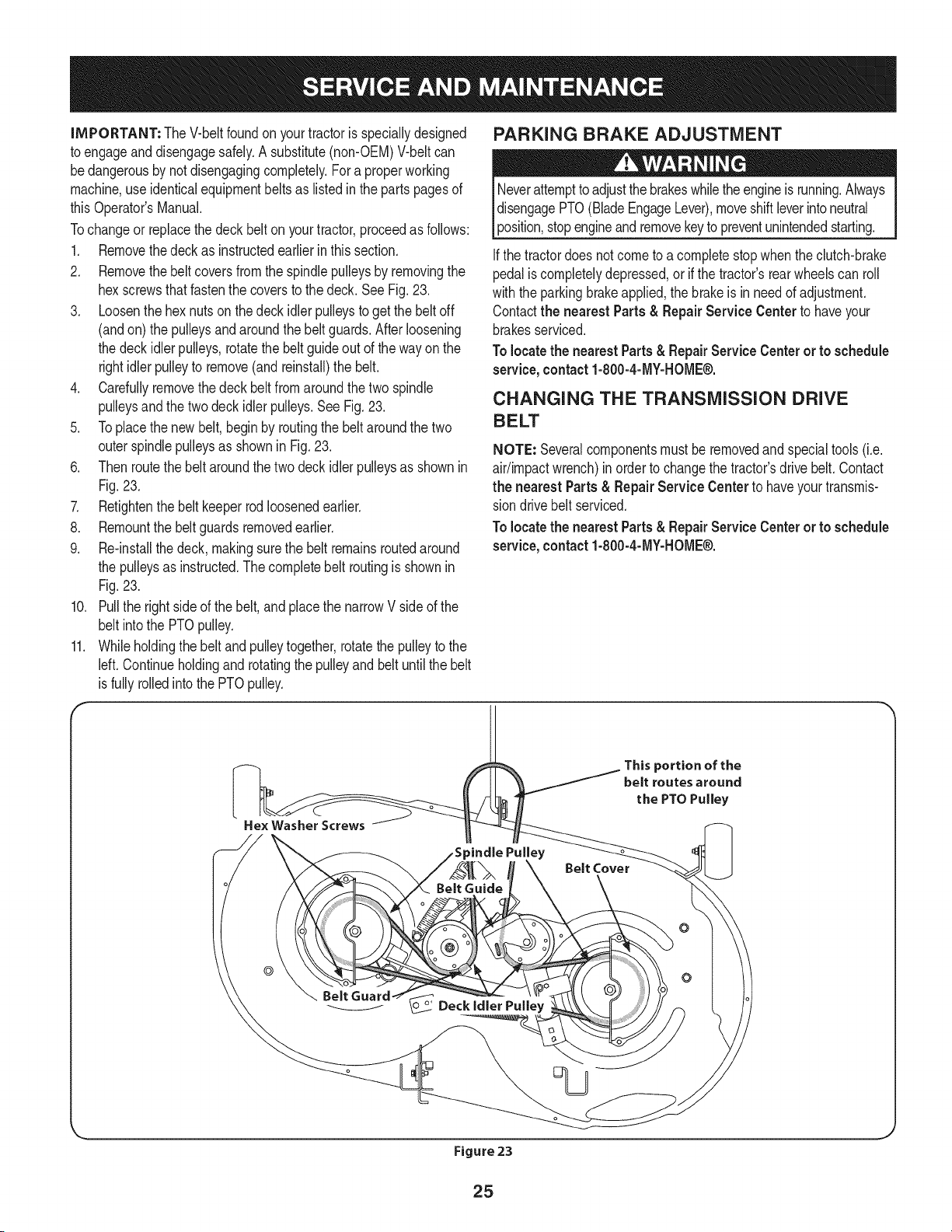
2. Removethebelt coversfromthe spindlepulleysby removingthe
hexscrewsthat fastenthe coversto the deck.See Fig. 23.
3. Loosenthe hex nutson thedeck idlerpulleysto get the beltoff
(andon) the pulleysandaroundthe beltguards.Afterloosening
the deck idlerpulleys,rotatethe beltguide out of thewayonthe
rightidler pulleyto remove(andreinstall)the belt.
4. Carefullyremovethe deckbeltfrom aroundthe twospindle
pulleysand thetwo deckidler pulleys.See Fig.23.
5. Toplacethe newbelt, begin by routingthe beltaroundthe two
outerspindlepulleysas shownin Fig.23.
6. Thenroutethe beltaroundthe twodeckidler pulleysas shownin
Fig.23.
7. Retightenthe belt keeperrod loosenedearlier.
8. Remountthebeltguardsremovedearlier.
9. Re-installthe deck,makingsurethe belt remainsroutedaround
the pulleysas instructed.Thecompletebelt routingis shownin
Fig.23.
10. Pullthe rightsideof thebelt,and placethe narrowV sideof the
belt intothe PTOpulley.
11. Whileholdingthe beltand pulleytogether,rotatethe pulleyto the
left. Continueholdingand rotatingthe pulleyand beltuntil thebelt
is fully rolledintothe PTOpulley.
F
PARKING BRAKE ADJUSTMENT
Neverattempttoadjustthe brakeswhilethe engineis running.Always
disengagePTO(BladeEngageLever),moveshiftleverintoneutral
3osition,stopengineandremovekeyto preventunintendedstarting.
Ifthe tractordoesnotcome to a completestopwhentheclutch-brake
pedalis completelydepressed,or if the tractor'srearwheelscan roll
withthe parkingbrakeapplied,thebrakeis inneed of adjustment.
Contactthe nearest Parts & Repair Service Centerto haveyour
brakesserviced.
Tolocatethe nearest Parts& RepairService Centeror to schedule
service,contact1-800-4-MY-HOME®.
CHANGING THE TRANSMISSION DRIVE
BELT
NOTE: Severalcomponentsmustbe removedandspecialtools(i.e.
air/impactwrench)in orderto changethetractor'sdrivebelt. Contact
the nearest Parts& Repair Service Centerto haveyourtransmis-
siondrivebelt serviced.
Tolocatethe nearest Parts& RepairService Centeror to schedule
service,contact1-800-4-MY-HOME®.
He× Washer Screws
This portion of the
belt routes around
the PTO Pulley
Belt Cover
o
Figure 23
25
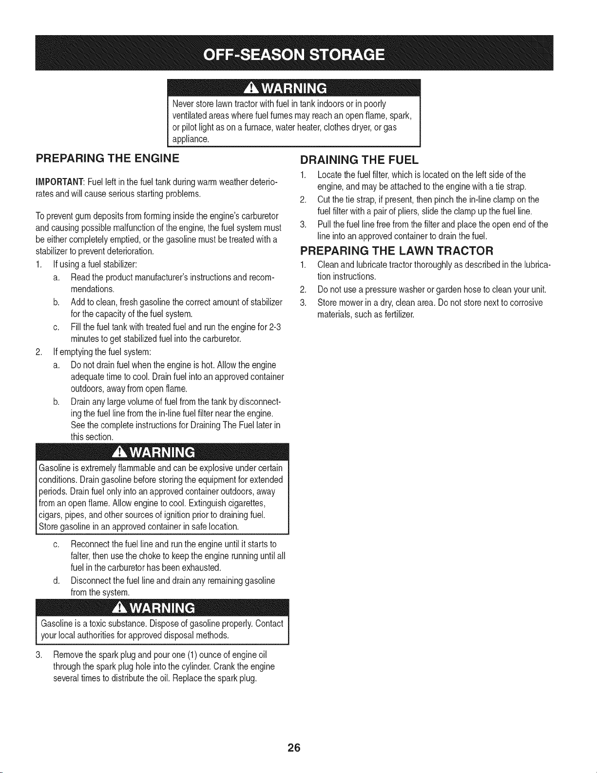
Neverstorelawntractorwithfuel intankindoorsor in poorly
ventilatedareaswherefuel fumesmay reachan openflame,spark,
or pilot lightas ona furnace,waterheater,clothesdryer,or gas
appliance.
PREPARING THE ENGINE
IMPORTANT:Fuelleft in the fueltank duringwarmweatherdeterio-
ratesandwillcauseseriousstartingproblems.
To preventgumdepositsfromforminginsidethe engine'scarburetor
andcausingpossiblemalfunctionof theengine,the fuelsystemmust
be eithercompletelyemptied,or the gasolinemustbe treatedwith a
stabilizerto preventdeterioration.
1. Ifusinga fuel stabilizer:
a. Readthe productmanufacturer'sinstructionsand recom-
mendations.
b. Addto clean,freshgasolinethe correctamountof stabilizer
for the capacityof the fuelsystem.
c. Fillthe fueltank with treatedfuel andrunthe enginefor 2-3
minutesto get stabilizedfuel intothe carburetor.
2. Ifemptyingthe fuel system:
a. Donot drainfuel whenthe engineis hot. Allowthe engine
adequatetimeto cool.Drainfuelinto an approvedcontainer
outdoors,awayfromopen flame.
b. Drainany largevolumeof fuel fromthetankby disconnect-
ingthe fuel line from the in-linefuel filter nearthe engine.
Seethe completeinstructionsfor DrainingThe Fuellaterin
this section.
Gasolineis extremelyflammableand can be explosiveundercertain
conditions.Draingasolinebeforestoringthe equipmentfor extended
periods.Drainfuel onlyinto anapprovedcontaineroutdoors,away
froman openflame.Allowengineto cool.Extinguishcigarettes,
cigars,pipes, and othersourcesof ignitionprior to drainingfuel.
Storegasolinein an approvedcontainerin safe location.
c. Reconnectthe fuel lineand run the engineuntilit startsto
falter,thenusethe choke to keepthe enginerunninguntilall
fuel in the carburetorhas beenexhausted.
d. Disconnectthefuel lineand drain any remaininggasoline
fromthe system.
DRAINING THE FUEL
1. Locatethe fuel filter,which is locatedon theleft sideof the
engine,and maybe attachedto the enginewith a tie strap.
2. Cutthe tie strap,if present,then pinchthe in-lineclampon the
fuel filter with a pairof pliers,slidethe clampup the fuel line.
3. Pullthe fuel line freefromthe filterand placetheopenend of the
line intoan approvedcontainerto drain the fuel.
PREPARING THE LAWN TRACTOR
1. Cleanand lubricatetractorthoroughlyas describedin the lubrica-
tion instructions.
2. Donot usea pressurewasheror gardenhoseto cleanyour unit.
3. Store mowerin a dry,cleanarea. Do notstorenextto corrosive
materials,such as fertilizer.
Gasolineis a toxic substance.Disposeof gasolineproperly.Contact
yourlocalauthoritiesforapproveddisposalmethods.
3. Removethe sparkplugandpourone(1)ounceof engineoil
throughthe sparkplughole intothe cylinder.Crankthe engine
severaltimesto distributethe oil. Replacethe sparkplug.
26
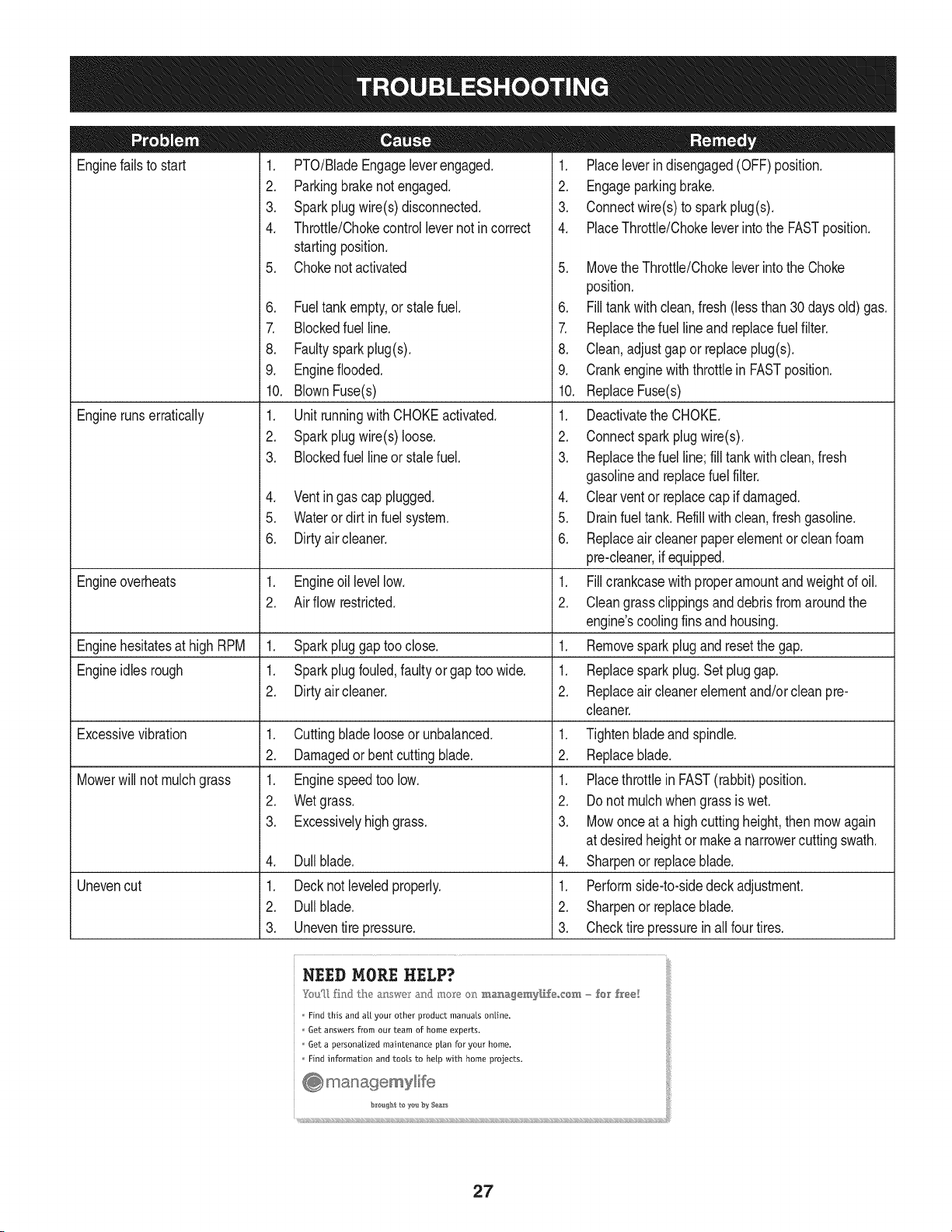
Enginefailsto start
Enginerunserratically
1. PTO/BladeEngageleverengaged.
2. Parkingbrakenotengaged.
3. Sparkplugwire(s) disconnected.
4. Throttle/Chokecontrollevernot incorrect
startingposition.
5. Chokenotactivated
6. Fueltank empty,or stale fuel.
7. Blockedfuel line.
8. Faultysparkplug(s).
9. Engineflooded.
10. BlownFuse(s)
1. Unitrunningwith CHOKEactivated.
2. Sparkplugwire(s) loose.
3. Blockedfuel lineor stalefuel.
4. Ventingas cap plugged.
5. Wateror dirt in fuel system.
6. Dirtyair cleaner.
Engineoverheats 1. Engineoillevellow. 1.
2. Airflow restricted. 2.
Enginehesitatesat high RPM 1. Sparkpluggaptoo close. 1.
Engineidles rough 1. Sparkplugfouled,faultyor gap too wide. 1.
2. Dirtyair cleaner. 2.
Excessivevibration
Mowerwill not mulchgrass
Unevencut
1. Cuttingbladelooseor unbalanced.
2. Damagedor bent cuttingblade.
1. Enginespeedtoo low.
2. Wetgrass.
3. Excessivelyhighgrass.
4. Dullblade.
1. Decknot leveledproperly.
2. Dullblade.
3. Uneventire pressure.
1. Placeleverindisengaged(OFF) position.
2. Engageparkingbrake.
3. Connectwire(s)to sparkplug(s).
4. PlaceThrottle/Chokeleverintothe FASTposition.
5. MovetheThrottle/Chokeleverintothe Choke
position.
6. Filltank with clean,fresh (less than 30 days old) gas.
7. Replacethe fuel line and replacefuel filter.
8. Clean,adjustgapor replaceplug(s).
9. Crankenginewiththrottlein FASTposition.
10. ReplaceFuse(s)
1. Deactivatethe CHOKE.
2. Connectsparkplugwire(s).
3. Replacethe fuel line;fill tankwithclean,fresh
gasolineandreplacefuel filter.
4. Clearventor replacecap if damaged.
5. Drainfuel tank. Refillwith clean,fresh gasoline.
6. Replaceair cleanerpaper elementor cleanfoam
pre-cleaner,if equipped.
Fillcrankcasewith properamountandweightof oil.
Cleangrassclippingsanddebrisfrom aroundthe
engine'scoolingfins and housing.
Removesparkplugandresetthe gap.
Replacespark plug.Set pluggap.
Replaceair cleanerelementand/orcleanpre-
cleaner.
1. Tightenbladeand spindle.
2. Replaceblade.
1. Placethrottlein FAST(rabbit)position.
2. Do notmulchwhen grassis wet.
3. Mowonceat a highcuttingheight,then mowagain
at desiredheightor makea narrowercuttingswath.
4. Sharpenor replaceblade.
1. Performside-to-sidedeck adjustment.
2. Sharpenor replaceblade.
3. Checktire pressureinallfour tires.
NEED MORE HELP?
_m_[_ fhlJ lhe a:__wc_r_:md mo_e o_ m_agemy[_,f÷,,,cem - for h'ee[
Find this and aft your other product manuals online.
Get answers from our team of home experts.
Get a personalized maintenance ptan for your home.
I:ind information and toots to help with home projects.
27
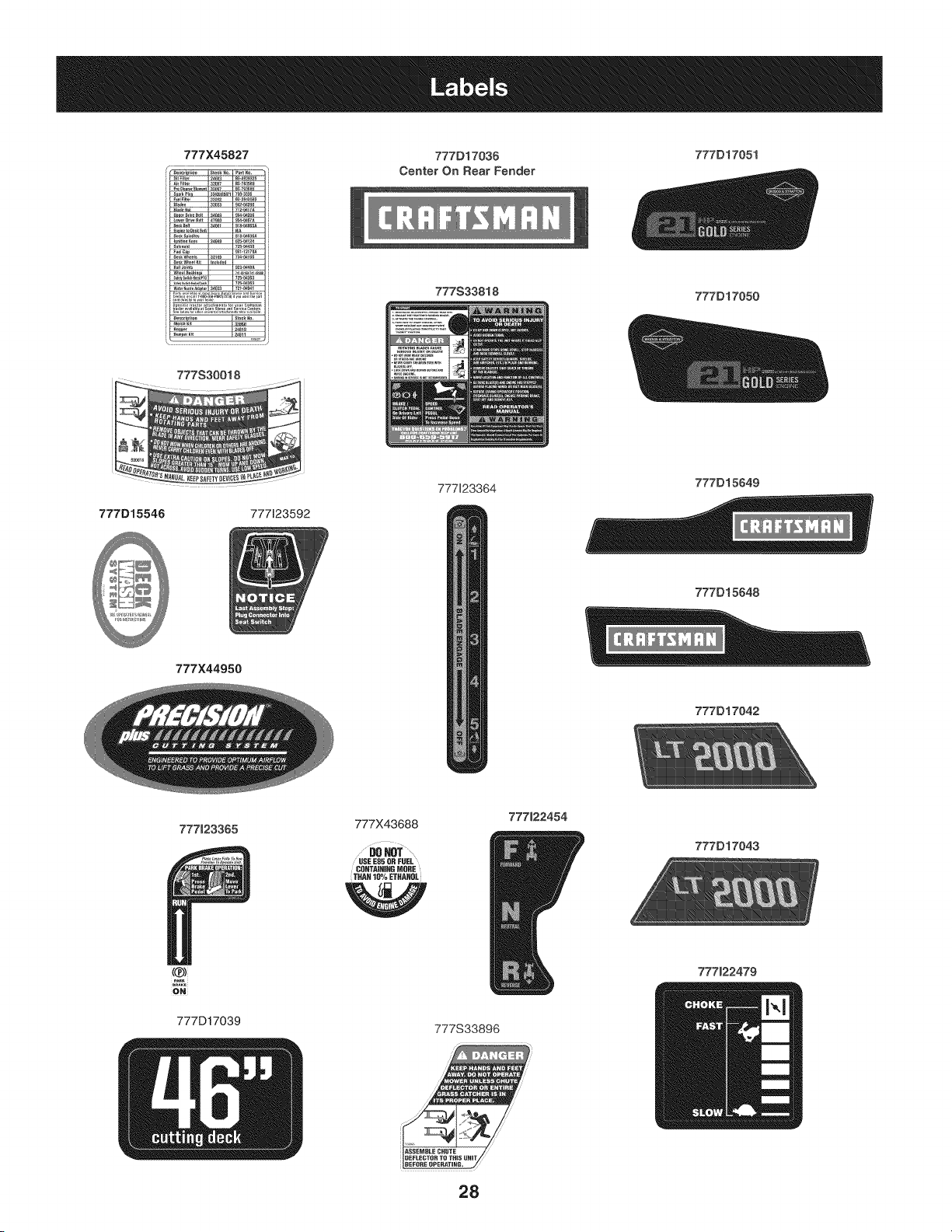
777X45827 777D1703(} 777D17051
Center On Rear Fender
777S30018
777533818
777D17050
777D15546
777X44950
777123592
777123364
777D15649
777D15648
777D17042
777J23365
ONi
777D17039
777X43688
.......
USE E85 OU FUEL
CUNTA_UmU MORE
THAN 10% ETUANUL
W
777122454
777S33896
28
777D17043
777122479

This page intentionally left blank. Use this page to make any notes regarding your tractor.
29
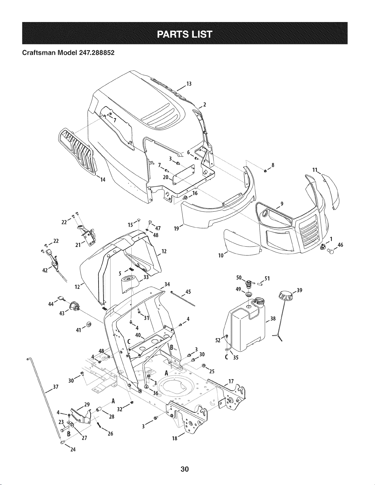
Craftsman IViodel 247.288852
10
17
3O
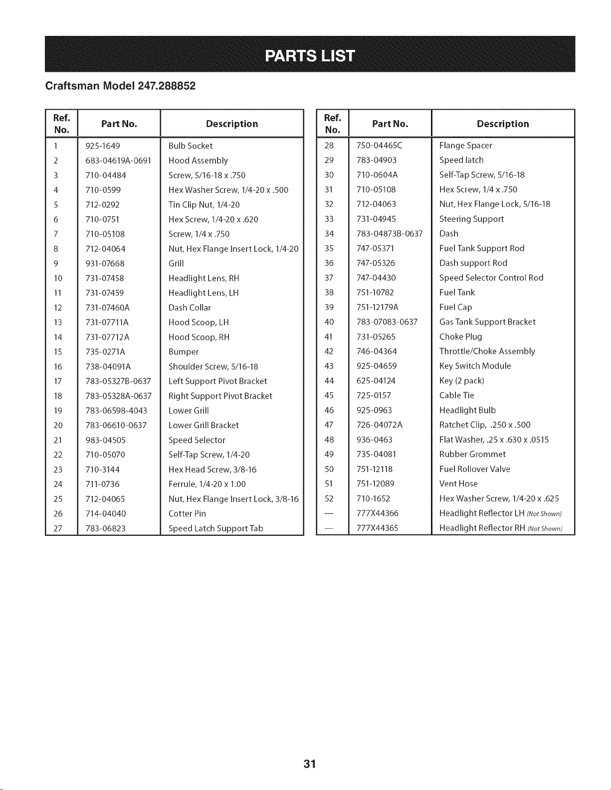
Craftsman Model 247.288852
Ref, [
No.
I 925-1649
2 683-04619A-0691
3 710-04484
4 710-0599
S 712-0292
6 710-0751
7 710-05108
8 712-04064
9 931-07668
10 731-07458
II 731-07459
12 731-07460A
13 731-07711A
14 731-07712A
15 735-0271A
16 738-04091A
17 783-05327B-0637
18 783-05328A-0637
19 783-06598-4043
20 783-06610-0637
21 983-04505
22 710-05070
23 710-3144
24 711-0736
25 712-04065
26 714-04040
27 783-06823
Part No. Description
Bulb Socket
Hood Assembly
Screw, 5/16-18 x .750
Hex Washer Screw, 1/4-20 x .500
Tin Clip Nut, 1/4-20
Hex Screw, 1/4-20 x .620
Screw, 1/4 x .750
Nut, Hex Flange Insert Lock, 1/4-20
Grill
Headlight Lens, RH
Headlight Lens, LH
Dash Collar
Hood Scoop, LH
Hood Scoop, RH
Bumper
Shoulder Screw, 5/16-18
Left Support Pivot Bracket
Right Support Pivot Bracket
Lower Grill
Lower Grill Bracket
Speed Selector
Self-Tap Screw, 1/4-20
Hex Head Screw, 3/8-16
Ferrule, 1/4-20 x 1.00
Nut, Hex Flange Insert Lock, 3/8-16
Cotter Pin
Speed Latch Support Tab
Ref, I
No,
28 750-04465C
29 783-04903
30 710-0604A
31 710-05108
32 712-04063
33 731-04945
34 783-04873B-0637
35 747-05371
36 747-05326
37 747-04430
38 751-10782
39 751-12179A
40 783-07083-0637
41 731-05265
42 746-04364
43 925-04659
44 625-04124
45 725-0157
46 925-0963
47 726-04072A
48 936-0463
49 735-04081
50 751-12118
51 751-12089
52 710-1652
-- 777X44366
-- 777X44365
Part No, Description
Flange Spacer
Speed latch
Self-Tap Screw, 5/16-18
Hex Screw, 1/4 x .750
Nut, Hex Flange Lock, 5/16-18
Steering Support
Dash
Fuel Tank Support Rod
Dash support Rod
Speed Selector Control Rod
Fuel Tank
Fuel Cap
Gas Tank Support Bracket
Choke Plug
Throttle/Choke Assembly
Key Switch Module
Key (2 pack)
Cable Tie
Headlight Bulb
Ratchet Clip, .250 x .500
Flat Washer, .25 x .630 x .0515
Rubber Grommet
Fuel Rollover Valve
Vent Hose
Hex Washer Screw, 1/4-20 x .625
Headlight Reflector LH (NotShown)
Headlight Reflector RH (NotShown)
31
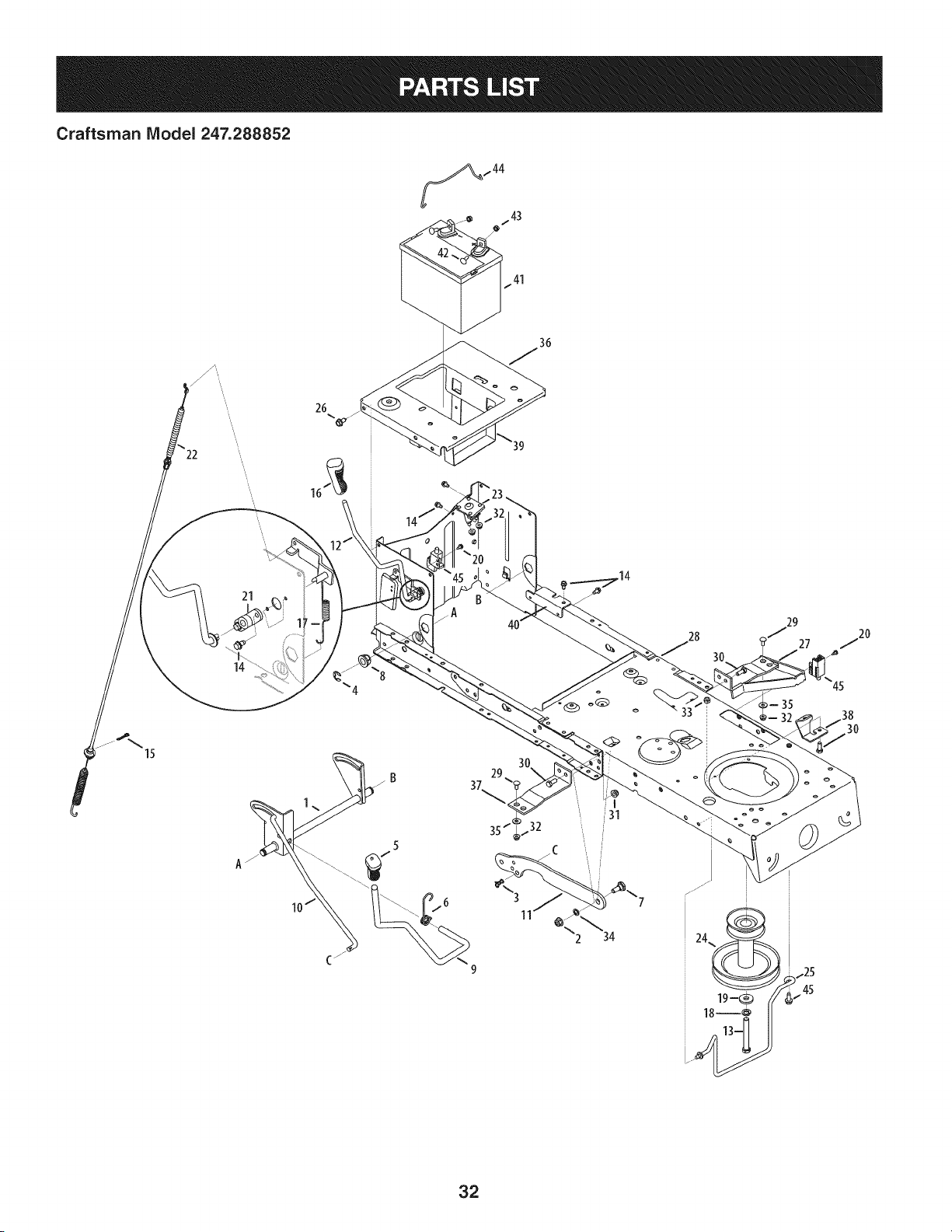
Craftsman IViodel 247.288852
26
15
21
14
37
29
29
27
45
30
32
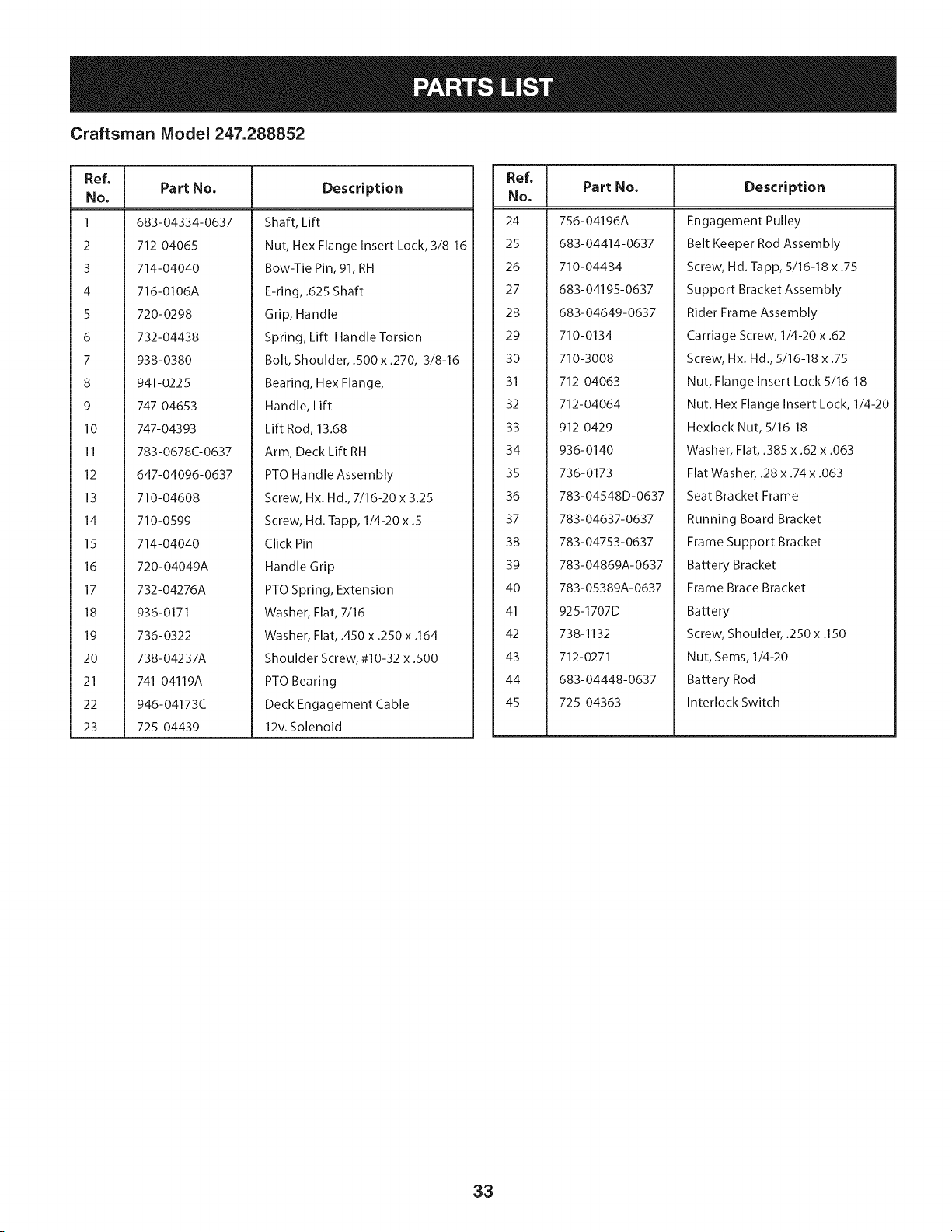
Craftsman Model 247.288852
Ref, [
No,
1 683-04334-0637
2 712-04065
3 714-04040
4 716-0106A
5 720-0298
6 732-04438
7 938-0380
8 941-0225
9 747-04653
10 747-04393
II 783-0678C-0637
12 647-04096-0637
13 710-04608
14 710-0599
15 714-04040
16 720-04049A
17 732-04276A
18 936-0171
19 736-0322
20 738-04237A
21 741-04119A
22 946-04173C
23 725-04439
Part No, Description
Shaft, Lift
Nut, Hex Flange Insert Lock, 3/8-16
Bow-Tie Pin, 91, RH
E-ring, .625 Shaft
Grip, Handle
Spring, Lift Handle Torsion
Bolt, Shoulder, .500 x .270, 3/8-16
Bearing, Hex Flange,
Handle, Lift
Lift Rod, 13.68
Arm, Deck Lift RH
PTO Handle Assembly
Screw, Hx. Hd., 7/16-20 x 3.25
Screw, Hd. Tapp, 1/4-20 x .5
Click Pin
Handle Grip
PTO Spring, Extension
Washer, Flat, 7/16
Washer, Flat, .450 x .250 x .164
Shoulder Screw, #10-32 x .500
PTO Bearing
Deck Engagement Cable
12v. Solenoid
Ref, I
No,
24 756-04196A
25 683-04414-0637
26 710-04484
27 683-04195-0637
28 683-04649-0637
29 710-0134
30 710-3008
31 712-04063
32 712-04064
33 912-0429
34 936-0140
35 736-0173
36 783-04548D-0637
37 783-04637-0637
38 783-04753-0637
39 783-04869A-0637
40 783-05389A-0637
41 925-1707D
42 738-1132
43 712-0271
44 683-04448-0637
45 725-04363
Part No, Description
Engagement Pulley
Belt Keeper Rod Assembly
Screw, Hd. Tapp, 5/16-18 x .75
Support Bracket Assembly
Rider Frame Assembly
Carriage Screw, 1/4-20 x .62
Screw, Hx. Hd., 5/16-18 x .75
Nut, Flange Insert Lock 5/16-18
Nut, Hex Flange Insert Lock, 1/4-20
Hexlock Nut, 5/16-18
Washer, Flat, .385 x .62 x .063
Flat Washer, .28 x .74 x .063
Seat Bracket Frame
Running Board Bracket
Frame Support Bracket
Battery Bracket
Frame Brace Bracket
Battery
Screw, Shoulder, .250 x .150
Nut, Sems, 1/4-20
Battery Rod
Interlock Switch
33
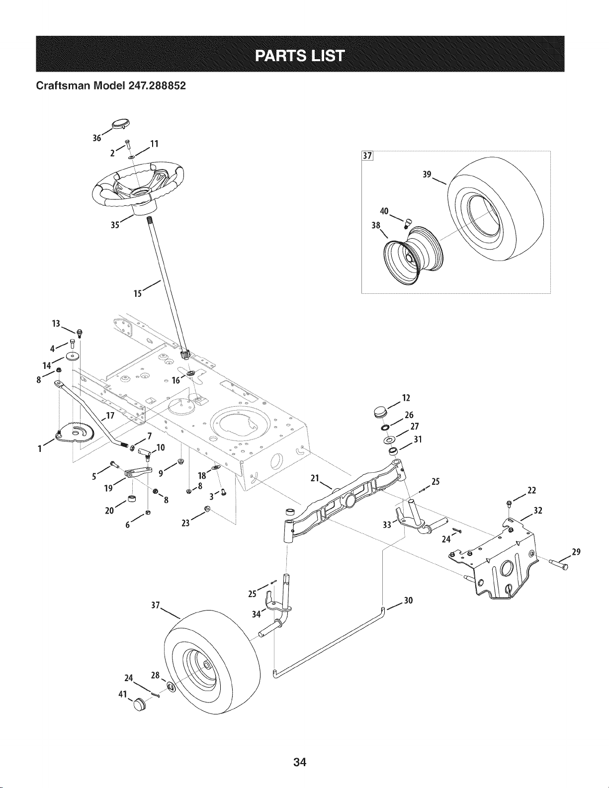
Craftsman IViodel 247.288852
4O
38
\
13
4j
24 28
12
QJ 26
o _ 27
_J31
29
34
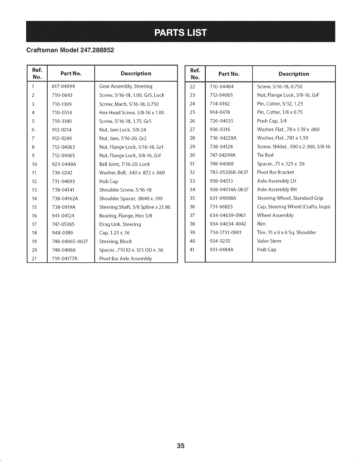
Craftsman Model 247.288852
Ref, I
No,
1 617-04094
2 710-0643
3 710-1309
4 710-0514
S 710-3180
6 912-0214
7 912-0240
8 712-04063
9 712-04065
10 923-0448A
11 736-0242
12 731-04693
13 738-04141
14 738-04162A
15 738-0919A
16 941-04124
17 747- 05385
18 948-0389
19 748-04065-0637
20 748-04068
21 719-04177A
Part No. Description
Gear Assembly, Steering
Screw, 5/16-18, 1.00, GrS, Lock
Screw, Mach, 5/16-18, 0.750
Hex Head Screw, 3/8-16 x 1.00
Screw, 5/16-18, 1.75, Gr5
Nut, Jam Lock, 3/8-24
Nut, Jam, 7/16-20, Gr2
Nut, Flange Lock, 5/16-18, Grf
Nut, Flange Lock, 3/8-16, Grf
Ball Joint, 7/16-20, Lock
Washer, Bell, .340 x .872 x .060
Hub Cap
Shoulder Screw, 5/16-18
Shoulder Spacer, .8840 x .190
Steering Shaft, 5/8 Spline x 21.86
Bearing, Flange, Hex 5/8
Drag Link, Steering
Cap, 1.25 x .16
Steering, Block
Spacer, .710 ID x .125 OD x .56
Pivot Bar Axle Assembly
Ref, I
No,
22 710-04484
23 712-04065
24 714-0162
25 914-0474
26 726-04035
27 936-0316
28 736-04228A
29 738-04128
30 747-04299A
31 748-04068
32 783-05326B-0637
33 938-04013
34 938-04014A-0637
35 631-04008A
36 731-06825
37 634-04639-0961
38 934-04634-4042
39 734-1731-0901
40 934-0255
41 931-0484A
Part No. Description
Screw, 5/16-18, 0.750
Nut, Flange Lock, 3/8-16, GrF
Pin, Cotter, 5/32, 1.25
Pin, Cotter, 1/8 x 0.75
Push Cap, 3/4
Washer, Flat, .78 x 1.59 x .060
Washer, Flat, .781 x 1.59
Screw, Shlder, .500 x 2.380, 3/8-16
Tie Rod
Spacer, .71 x .125 x .56
Pivot Bar Bracket
Axle Assembly LH
Axle Assembly RH
Steering Wheel, Standard Grip
Cap, Steering Wheel (Crafts. logo)
Wheel Assembly
Rim
Tire, 15 x 6 x 6 Sq. Shoulder
Valve Stem
Hub Cap
35
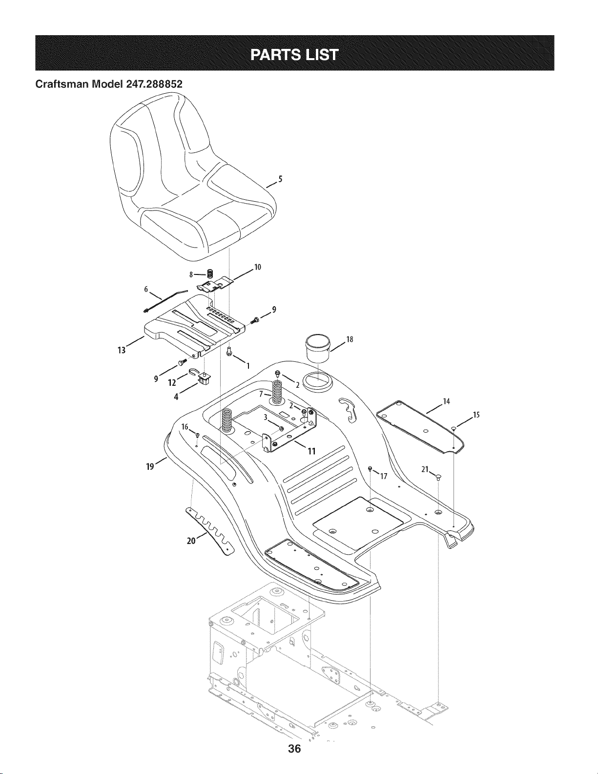
Craftsman Model 247.288852
13
\
11
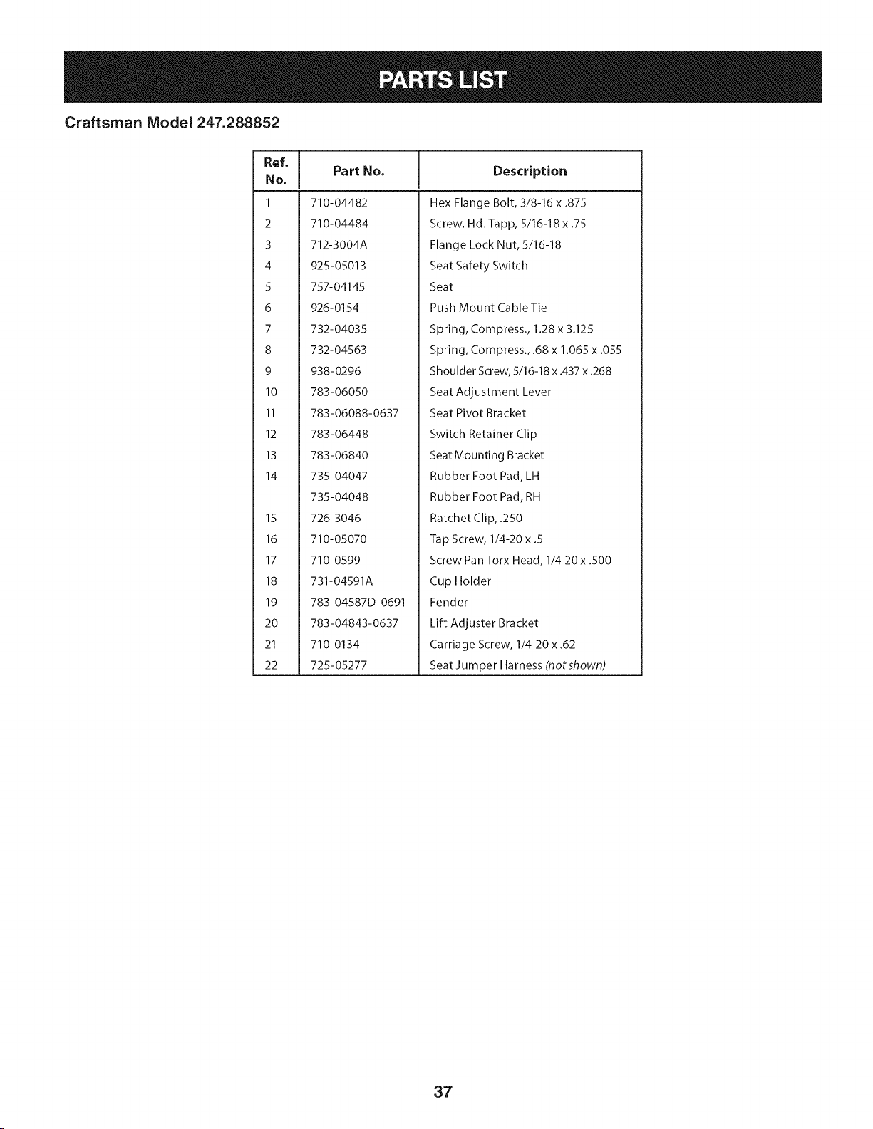
Craftsman Model 247.288852
Ref, [
No,
1 710-04482
2 710-04484
3 712-3004A
4 925-05013
5 757-04145
6 926-0154
7 732-04035
8 732-04563
9 938-0296
10 783-06050
II 783-06088-0637
12 783-06448
13 783-06840
14 735-04047
735-04048
15 726-3046
16 710-05070
17 710-0599
18 731-04591A
19 783-04587D-0691
20 783-04843-0637
21 710-0134
22 725-05277
Part No, Description
Hex Flange Bolt, 3/8-16 x .875
Screw, Hd. Tapp, 5/16-18 x .75
Flange Lock Nut, 5/16-18
Seat Safety Switch
Seat
Push Mount Cable Tie
Spring, Compress., 1.28 x 3.125
Spring, Compress., .68 x 1.065 x .055
Shoulder Screw, 5/16-18 x .437 x .268
Seat Adjustment Lever
Seat Pivot Bracket
Switch Retainer Clip
Seat Mounting Bracket
Rubber Foot Pad, LH
Rubber Foot Pad, RH
Ratchet Clip, .250
Tap Screw, 1/4-20 x .5
Screw Pan Torx Head, I/4-20x .500
Cup Holder
Fender
Lift Adjuster Bracket
Carriage Screw, 1/4-20 x .62
Seat Jumper Harness (notshown)
37
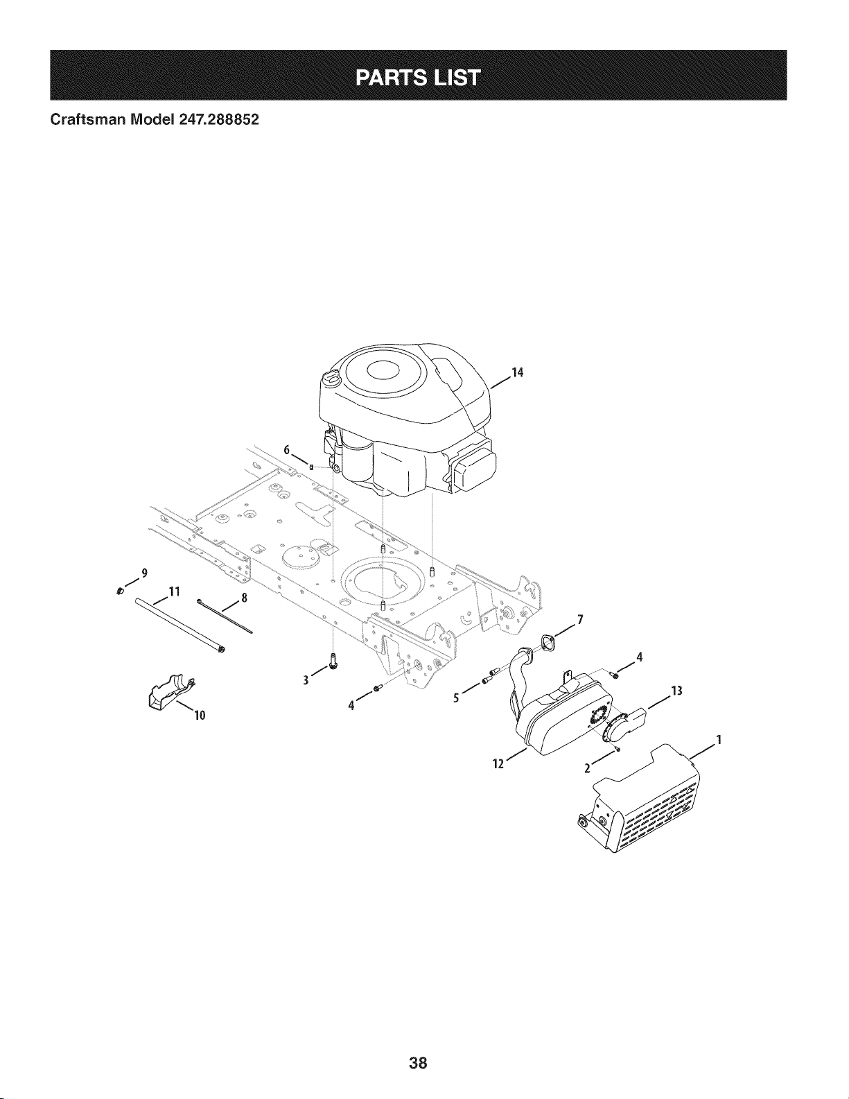
Craftsman IViodel 247.288852
13
38
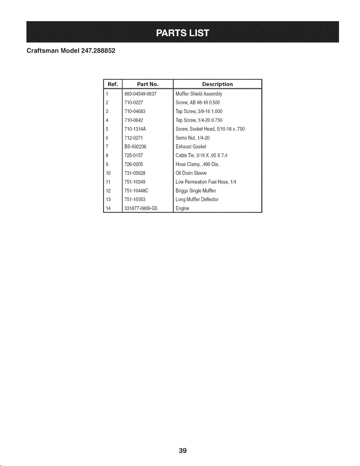
Craftsman IViodel 247.288852
I
Ref.
I Part No.
1 683-04549-0637
2 710-0227
3 710-04683
4 710-0642
5 710-1314A
6 712-0271
7 BS-692236
8 725-0157
9 726-0205
10 731-05628
11 751-10349
12 751-10448C
13 751-10353
14 331877-0869-G5
Description
MufflerShieldAssembly
Screw,AB #8-180.500
TapScrew,3/8-16 1.000
TapScrew,1/4-200.750
Screw,SocketHead,5/16-18x .750
Sems Nut, 1/4-20
ExhaustGasket
CableTie,3/16 X .05X 7.4
HoseClamp,.490 Dia.
Oil DrainSleeve
LowPermeationFuelHose,1/4
BriggsSingleMuffler
LongMufflerDeflector
Engine
39
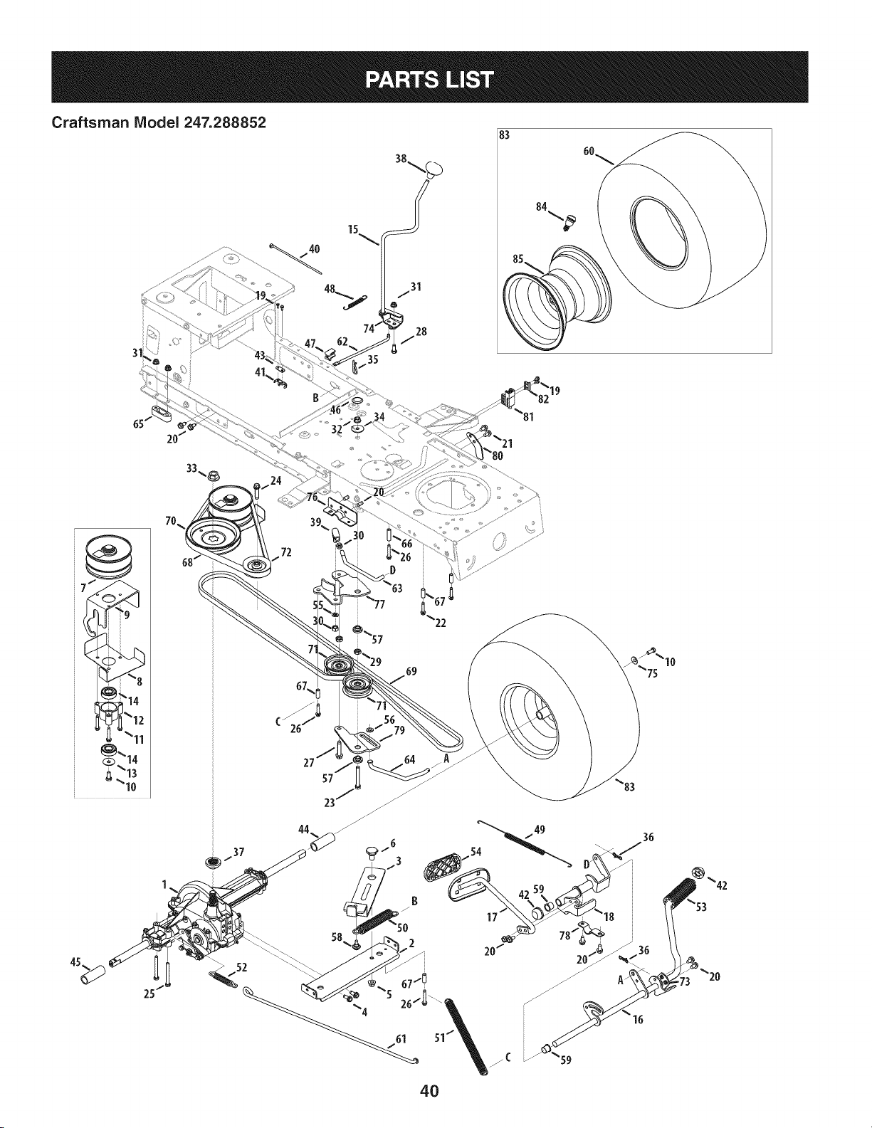
Craftsman Model 247.288852
83
15
.40
31
35
19
72
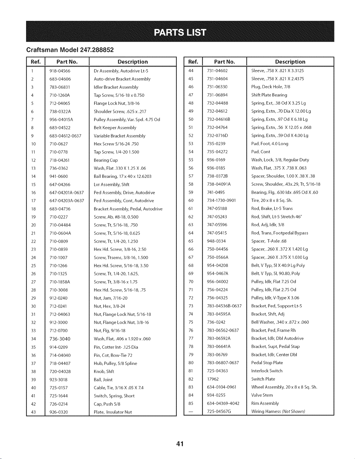
Craftsman Model 247.288852
I
Ref.
I Part No.
1 918-04566
2 683-04606
3 783-06831
4 710-1260A
5 712-04065
6 738-0322A
7 956-04015A
8 683-04522
9 683-04612-0637
10 710-0627
II 710-0778
12 718-04261
13 736-0362
14 941-0600
15 647-04266
16 647-04201A-0637
17 647-04203A-0637
18 683-04736
19 710-0227
20 710-04484
21 710-0604A
22 710-0809
23 710-0859
24 710-1007
25 710-1266
26 710-1325
27 710-1858A
28 710-3008
29 912-0240
30 712-0241
31 712-04063
32 912-3000
33 712-0700
34 736-3040
35 914-0209
36 714-04040
37 718-04407
38 720-04028
39 923-3018
40 725-0157
41 725-1644
42 726-0214
43 926-0320
Description
Dr Assembly, Autodrive Lt-5
Auto-drive Bracket Assembly
Idler Bracket Assembly
Tap Screw, 5/16-18 x 0.750
Flange Lock Nut, 3/8-16
Shoulder Screw, .625 x .217
Pulley Assembly, Var. Spd. 4.75 Od
Belt Keeper Assembly
Variable Bracket Assembly
Hex Screw 5/16-24.750
Tap Screw, 1/4-20 1.500
Bearing Cup
Wash, Flat .330 X 1.25 X .06
Ball Bearing, 17 x 40 x 12.6203
Lvr Assembly, Shft
Ped Assembly, Drive, Autodrive
Ped Assembly, Cont, Autodrive
Bracket Assembly, Pedal, Autodrive
Screw, Ab, #8-18, 0.500
Screw, Tt, 5/16-18, .750
Screw, Tt, 5/16-18, 0.625
Screw, Tt, 1/4-20, 1.250
Hex Hd. Screw, 3/8-16, 2.50
Screw, Ttsems, 3/8-16, 1.500
Hex Hd. Screw, 5/16-18, 3.50
Screw, Tt, 1/4-20, 1.625,
Screw, Tt, 3/8-16 x 1.75
Hex Hd. Screw, 5/16-18, .75
Nut, Jam, 7/16-20
Nut, Hex, 3/8-24
Nut, Flange Lock Nut, 5/16-18
Nut, Flange Lock Nut, 3/8-16
Nut, Fig, 9/16-18
Wash, Flat, .406 x 1.920 x .060
Pin, Cotter Int- .125 Dia
Pin, Cot, Bow-Tie 72
Hub, Pulley, 5/8 Spline
Knob, Shft
Ball, Joint
Cable, Tie, 3/16 X .05 X 7.4
Switch, Spring, Short
Cap, Push 5/8
Plate, Insulator Nut
|
Ref,
[ Part No,
44 731-04602
45 731-04604
46 731-06330
47 731-06894
48 732-04488
49 732-04612
50 732-046163
51 732-04764
52 732-0716D
53 735-0239
54 735-04272
55 936-0169
56 936-0185
57 738-0372B
58 738-04091A
59 741-0495
60 734-1730-0901
61 747-05188
62 747-05243
63 747-05596
64 747-05415
65 948-0334
66 750-04456
67 750-0566A
68 954-04208
69 954-0467A
70 956-04002
71 756-04224
72 756-04325
73 783-04536B-0637
74 783-04595A
75 736-0242
76 783-06562-0637
77 783-06592A
78 783-06641A
79 783-06769
80 783-06807-0637
81 725-04363
82 17962
83 634-0104-0961
84 934-0255
85 634-04369-4042
-- 725-045670
Description
Sleeve, .758 X .821 X 3.3125
Sleeve, .758 X .821 X 2.4375
Plug, Deck Hole, 7/8
Shift Plate Bearing
Spring, Ext, .38 Od X 3.25 Lg
Spring, Extn, .70 Dia X 12.00 Lg
Spring, Extn, .97 Od X 6.18 Lg
Spring, Extn, .56 X 12.05 x .068
Spring, Extn, .59 Od X 4.00 Lg
Pad, Foot, 4.0 Long
Pad, Cont
Wash, Lock, 3/8, Regular Duty
Wash, Flat, .375 X .738 X .063
Spacer, Shoulder, 1.O0 X .38 X .38
Screw, Shoulder, .43x.29, Tt, 5/16-18
Bearing, Fig, .630 Idx .695 Od X .60
Tire, 20 x 8 x 8 Sq. Sh.
Rod, Brake, Lt-5 Trans
Rod, Shift, Lt-5 Stretch 46"
Rod, Adj, Idlr, 3/8
Rod, Trans, Footpedal Bypass
Spacer, T-Axle .68
Spacer, .260 X .372 X 1.420 Lg
Spacer, .260 X .375 X 1.030 Lg
Belt, V Typ, 51 X 40.9 Lg Poly
Belt, V Typ, 51, 90.80, Poly
Pulley, Idlr, Flat 7.25 Od
Pulley, Idlr, Flat 2.75 Od
Pulley, Idlr, V-Type X 3.06
Bracket, Ped, Support Lt-5
Bracket, Shft, Adj
Bell Washer, .340 x .872 x .060
Bracket, Ped, Frame Rh
Bracket, Idlr, Dbl Autodrive
Bracket, Supt, Pedal Stap
Bracket, Idlr, Center Dbl
Pedal Stop Plate
Interlock Switch
Switch Plate
Wheel Assembly, 20 x 8 x 8 Sq. Sh.
Valve Stem
Rim Assembly
Wiring Harness (NotShown)
41
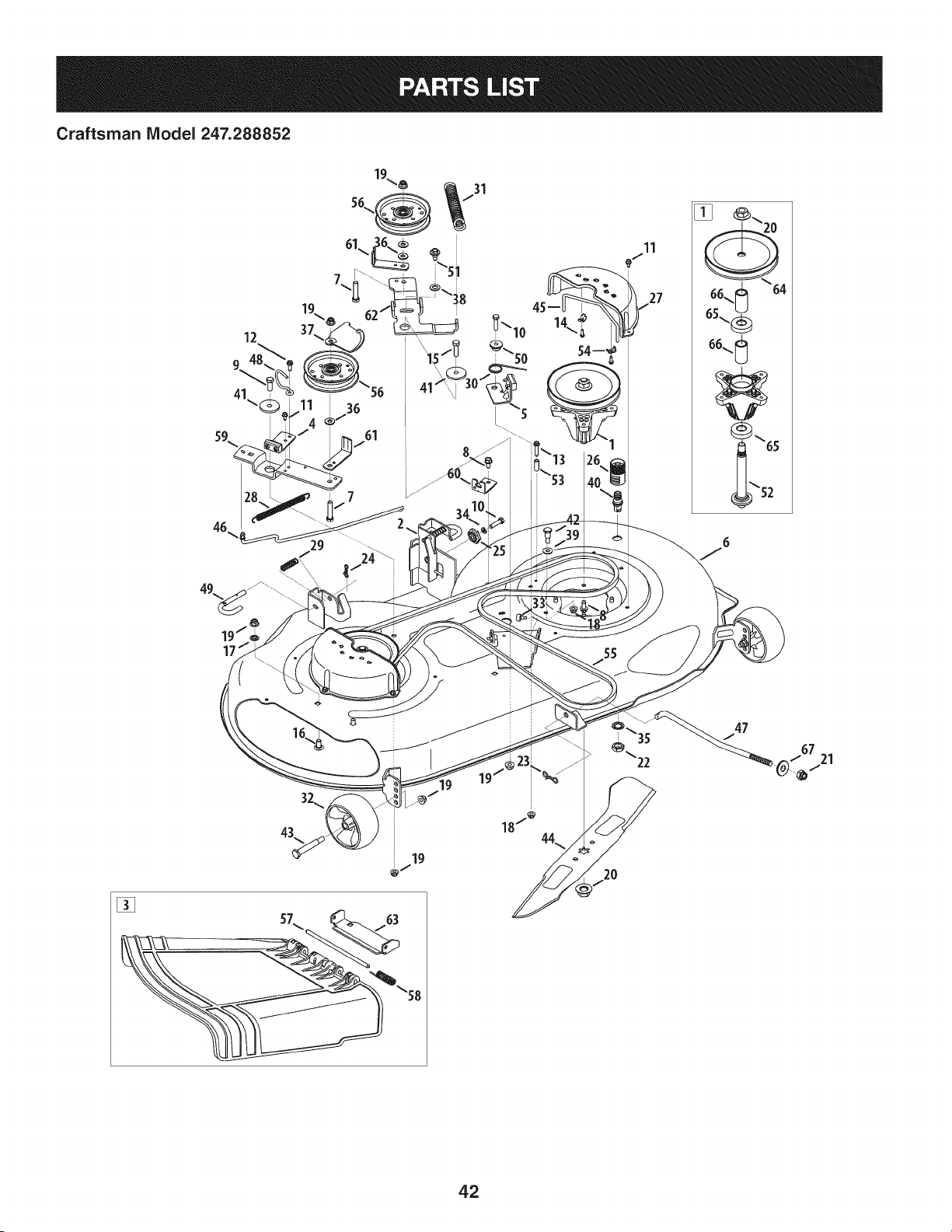
Craftsman IViodel 247.288852
42
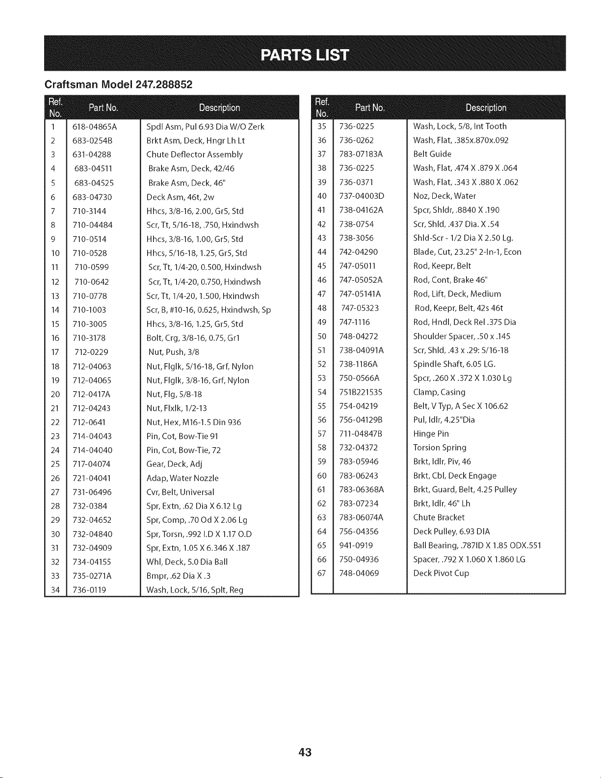
Craftsman Model 247.288852
m
m
1
2
3
4
5
6
7
8
9
10
11
12
13
14
15
16
17
18
19
20
21
22
23
24
25
26
27
28
29
3O
31
32
33
34
618-04865A
683-0254B
631-04288
683-04511
683-04525
683-04730
710-3144
710-04484
710-0514
710-0528
710-0599
710-0642
710-0778
710-1003
710-3005
710-3178
712-0229
712-04063
712-04065
712-0417A
712-04243
712-0641
714-04043
714-04040
717-04074
721-04041
731-06496
732-0384
732-04652
732-04840
732-04909
734-04155
735-0271A
736- 0119
Spdl Asm, Pul 6.93 Dia W/O Zerk
Brkt Asm, Deck, Hngr Lh Lt
Chute Deflector Assembly
Brake Asm, Deck, 42/46
Brake Asm, Deck, 46"
Deck Asm, 46t, 2w
Hhcs, 3/8-16, 2.00, GrS, Std
Scr, Tt, 5/16-18, .750, Hxindwsh
Hhcs, 3/8-16, 1.00, GrS, Std
Hhcs, 5/16-18, 1.25, GrS, Std
Scr, Tt, 1/4-20, 0.500, Hxindwsh
Scr, Tt, 1/4-20, 0.750, Hxindwsh
Scr, Tt, 1/4-20, 1.500, Hxindwsh
Scr, B, #10-16, 0.625, Hxindwsh, Sp
Hhcs, 3/8-16, 1.25, GrS, Std
Bolt, Crg, 3/8-16, 0.75, Grl
Nut, Push, 3/8
Nut, Flglk, 5/16-18, Grf, Nylon
Nut, Flglk, 3/8-16, Grf, Nylon
Nut, Fig, 5/8-18
Nut, Flxlk, 1/2-13
Nut, Hex, M16-1.5 Din 936
Pin, Cot, Bow-Tie 91
Pin, Cot, Bow-Tie, 72
Gear, Deck, Adj
Adap, Water Nozzle
Cvr, Belt, Universal
Spr, Extn, .62 Dia X 6.12 Lg
Spr, Comp, .70 Od X 2.06 Lg
Spr, Torsn, .992 I.D X 1.17 O.D
Spr, Extn, 1.05 X 6.346 X .187
Whl, Deck, S.0 Dia Ball
Bmpr, .62 Dia X .3
Wash, Lock, 5/16, Spit, Reg
m
35
36
37
38
39
4O
41
42
43
44
45
46
47
48
49
5O
51
52
53
54
55
56
57
58
59
6O
61
62
63
64
65
66
67
736-0225
736-0262
783-07183A
736-0225
736-0371
737-04003D
738-04162A
738-0754
738-3056
742-04290
747-05011
747-05052A
747-05141A
747-05323
747-1116
748-04272
738-04091A
738-1186A
750-0566A
751B221535
754-04219
756-04129B
711-04847B
732-04372
783-05946
783-06243
783-06368A
783-07234
783-06074A
756-04356
941-0919
750-04936
748-04069
Wash, Lock, 5/8, Int Tooth
Wash, Flat, .385x.870x.092
Belt Guide
Wash, Flat, .474 X .879 X .064
Wash, Flat, .343 X .880 X .062
Noz, Deck, Water
Spcr, Shldr, .8840 X .190
Scr, Shld, .437 Dia. X .54
Shld-Scr - 1/2 Dia X 2.50 Lg.
Blade, Cut, 23.25" 2-1n-1, Econ
Rod, Keepr, Belt
Rod, Cont, Brake 46"
Rod, Lift, Deck, Medium
Rod, Keepr, Belt, 42s 46t
Rod, Hndl, Deck Rel .375 Dia
Shoulder Spacer, .50 x .145
Scr, Shld, .43 x .29:5/16-18
Spindle Shaft, 6.05 LG.
Spcr, .260 X .372 X 1.030 Lg
Clamp, Casing
Belt, V Typ, A Sec X 106.62
Pul, Idlr, 4.25"Dia
Hinge Pin
Torsion Spring
Brkt, Idlr, Piv, 46
Brkt, Cbl, Deck Engage
Brkt, Guard, Belt, 4.25 Pulley
Brkt, Idlr, 46" Lh
Chute Bracket
Deck Pulley, 6.93 DIA
Ball Bearing, .7871D X 1.85 ODX.SS1
Spacer, .792 X 1.060 X 1.860 LG
Deck Pivot Cup
43
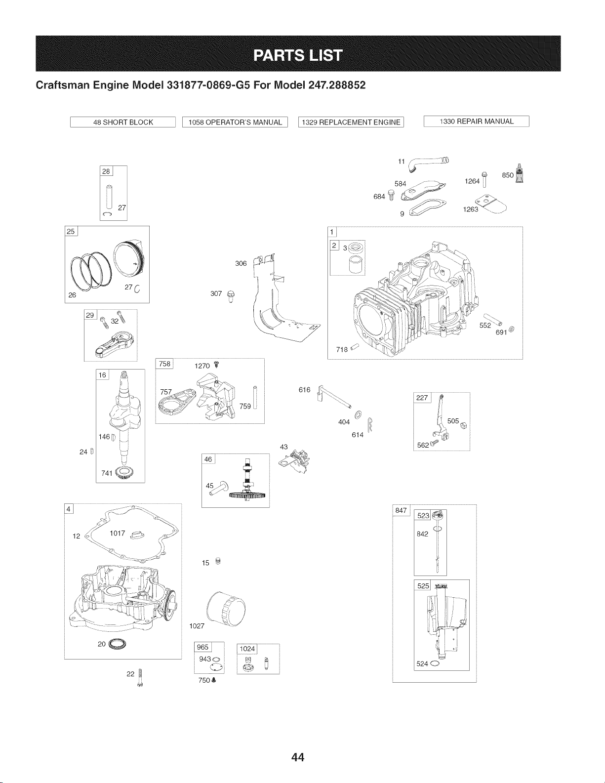
Craftsman Engine IViodel 331877=0869=G5 For IViodel 247.288852
48 SHORT BLOCK
1058 OPERATOR'S MANUAL ] I1329 REPLACEMENT ENGINE ]
1330 REPAIR MANUAL
26
12 1017_i_2__'_ _-'-.__i i
200
22
306
307
U
k _
15 _
1027
75O &
43
616
11 ,_
584 ..-/_. __ 1264
9 _ 1263 _-. y
552 _
691 _
718
404 ion.,505
614 _-,'-_¢,_
562 _ _"
847 _
524 d_7,
44
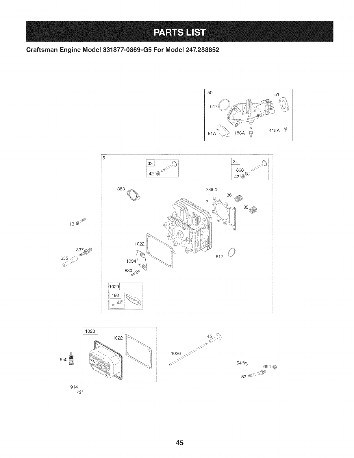
Craftsman Engine Model 331877=0869=G5 For Model 247.288852
5__ 51
51A
186A _ 415A
13_
635_
883
1022
617
i1029}
85O
102
914
1026 _
54%
654 _
53 .......
45
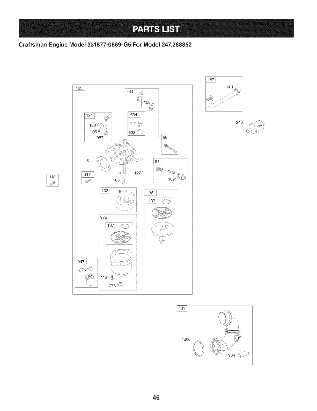
Craftsman Engine IViodel 331877-0869-G5 For IViodel 247.288852
125
13o 1
95 '_ _
987
51
lO2
1270
1091 {{L#
947
276 <_')
_ 1127
_ 276 '-<_
601
24O
1266
46
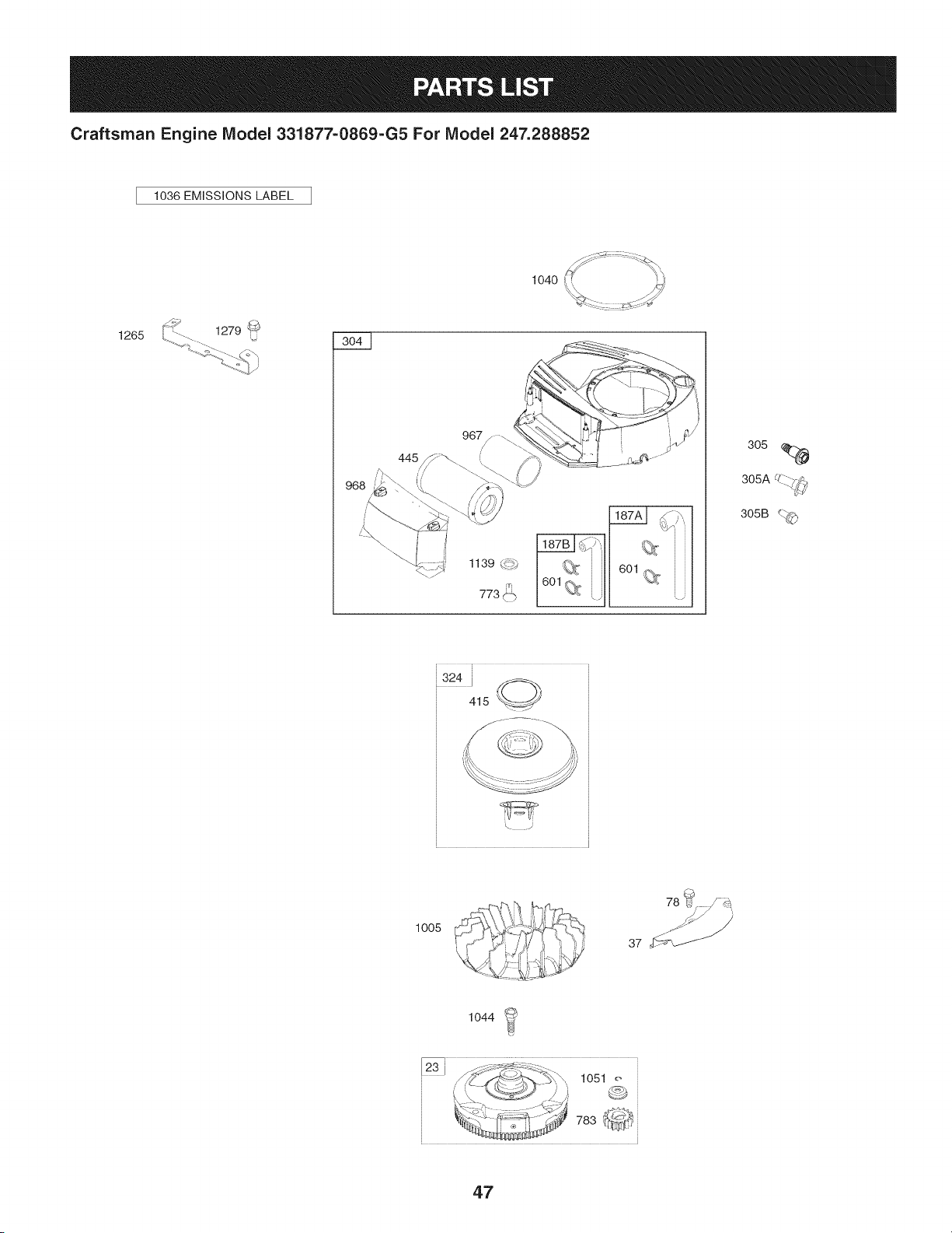
Craftsman Engine IViodel 331877=0869=G5 For IViodel 247.288852
1036 EMiSSiONS LABEL
1265
1139 _._,
305
UZ_--..
305A -.. 7_',
305B _._
,324 i _,
415 _//
:!!!i!!--_
\ .J
1005
78 _¢
37 '_f_
1044
47
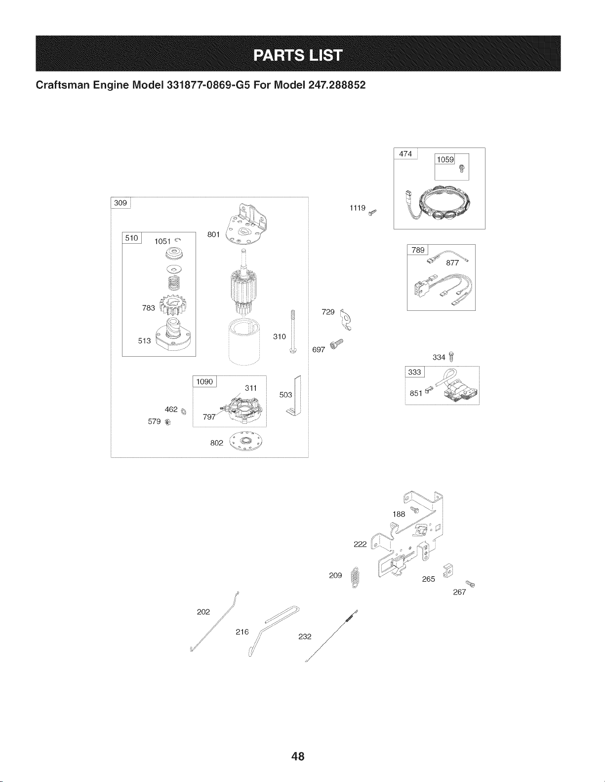
Craftsman Engine IViodel 331877-0869-G5 For IViodel 247.288852
309
1051 <"
783
513
801
310 iii
462 _;
579 _
802
729
697 _
1119
474
334
851
216
2O9
,,,_/ 232
265
267
48
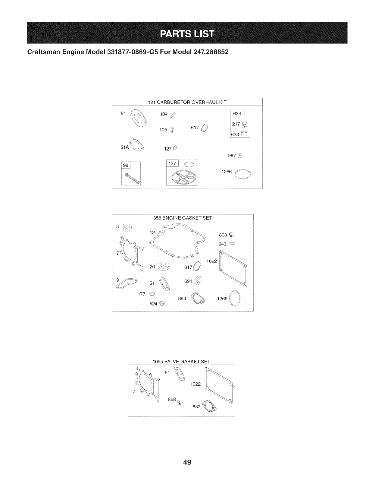
Craftsman Engine Model 331877=0869=G5 For Model 247.288852
51
121 CARBURETOR OVERHAUL KIT
104 _lO50 61__,
127 (_'
987 4_b
, 1266 _ ;_" ;_
ti
/
358 ENGINE GASKET SET
12
1o22
,_
691 _'7//'
1266
1095 VALVE GASKET SET
51
1022
49

Craftsman Engine Model 331877=0869=G5 For Model 247.288852
I
Ref,
I Part No.
No,
I
1 794128
2 399265
3 391086s
4 697188
5 796026
7 794114
9 697109
II 794683
12 697110
13 793988
15 690946
16 797579
20 795387
22 692125
23 698281
24 796335
25 795858
795877
26 794126
794127
27 698469
28 795861
29 794122
32 791118
33 792868
34 791935
35 691279
36 691279
37 699882
42 499586
43 691968
45 690564
46 793880
48 795446
50 796180
51 692137
51A 794312
53 690227
54 691148
78 691693
94 793610
95 690718
Description
Cylinder Assembly
Bushing/Seal Kit (Magneto Side)
Seal-Oil (Magneto Side)
Sump-Engine
Head-Cylinder
Gasket-Cylinder Head
Gasket-Breather
Tube-Breather
Gasket-Crankcase
Screw (Cylinder Head)
Plug-Oil Drain
Crankshaft
Seal-Oil (PTO Side)
Screw (Crankcase Cover/Sump)
Flywheel
Key-Flywheel (Steel)
Piston Assembly (Standard)
Piston Assembly (020" Oversize)
Ring Set (Standard)
Ring Set (.020" Oversize)
Lock-Piston Pin
Pin-Piston
Rod-Connecting
Screw (Connecting Rod)
Valve-Exhaust
Valve-Intake
Spring-Valve (Intake)
Spring-Valve (Exhaust)
Guard-Flywheel
Keeper-Valve
Slinger-Governor/Oil
Tappet-Valve
Camshaft
Short Block
Manifold-Intake
Gasket-Intake
Gasket-Intake
Stud (Carburetor)
Screw (Intake Manifold)
Screw (Flywheel Guard)
Kit-Idle Mixture
Screw (Throttle Valve)
Ref,
No,
98 695408
104 694918
105 696136
108 695419
117 796251
118 791406
121 796184
125 796587
127 690727
130 792747
131 792765
133 694914
135 698780
137 698781
141 792777
146 691639
186 794873
187 791805
187A 791806
187B 791744
188 691693
192 691986
202 691841
209 692208
216 691840
217 695409
222 694042
227 691374
232 691842
238 691843
240 394358s
265 691024
267 794904
276 695410
304 798670
305 697102
305A 793376
305B 795891
306 794953
307 691693
309 693551
I Part No, Description
Kit-Idle Speed
Pin-Float Hinge
Valve-Float Needle
Valve-Choke
Jet-Main (Standard)
Jet-Main (High Altitude)
Kit-Carburetor Overhaul
Carburetor
Plug-Welch
Valve-Throttle
Kit-Throttle Shaft
Float-Carburetor
Tube-Fuel Transfer
Gasket-Float Bowl
Kit-Choke Shaft
Key-Timing
Hose-Connector (Intake Manifold)
Line-Fuel (Formed) (Cut to Length)
Line-Fuel (Formed) (21") (Cut to Length)
Line-Fuel (Formed) (14") (Cut to Length)
Screw (Control Bracket)
Adjuster-Rocker Arm
Link-Mechanical Governor
Spring-Governor (Green)
Link-Choke
Spring-Choke Return
Bracket-Control
Lever-Governor Control
Spring-Governor Link
Cap-Valve
Filter-Fuel
Clamp-Casing
Screw (Casing Clamp)
Washer-Sealing
Housing-Blower
Screw (Blower Housing) (1/4-20x1.14)
Screw (Blower Housing) (1/4-20x.68)
Screw (Blower Housing) (Blower Housing to
Elbow)
Shield-Cylinder
Screw (Cylinder Shield)
Motor-Starter
50
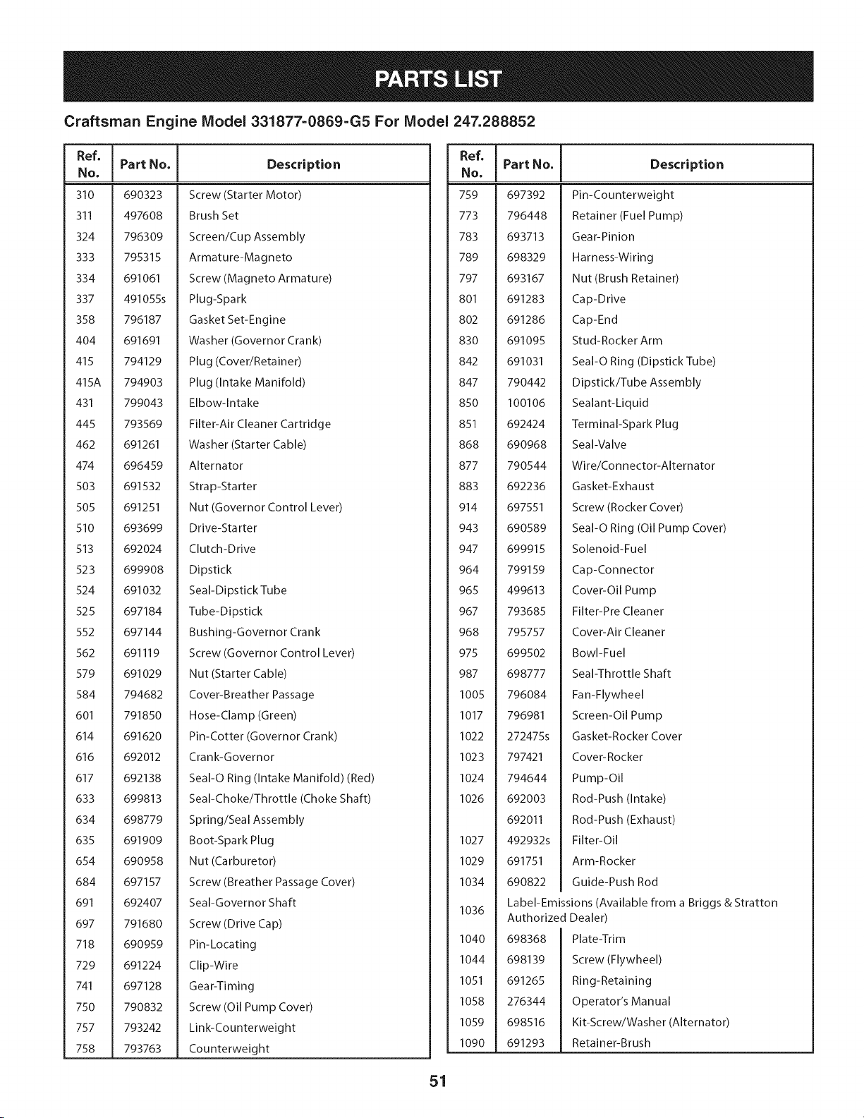
Craftsman Engine Model 331877-0869-G5 For Model 247.288852
I Part No. Description
Ref. Ref.
No. I No.
310 690323
311 497608
324 796309
333 795315
334 691061
337 491055s
358 796187
404 691691
415 794129
415A 794903
431 799043
445 793569
462 691261
474 696459
503 691532
505 691251
510 693699
513 692024
523 699908
524 691032
525 697184
552 697144
562 691119
579 691029
584 794682
601 791850
614 691620
616 692012
617 692138
633 699813
634 698779
635 691909
654 690958
684 697157
691 692407
697 791680
718 690959
729 691224
741 697128
750 790832
757 793242
758 793763
Screw (Starter Motor)
Brush Set
Screen/Cup Assembly
Armature-Magneto
Screw (Magneto Armature)
Plug-Spark
Gasket Set-Engine
Washer (Governor Crank)
Plug (Cover/Retainer)
Plug (Intake Manifold)
Elbow-Intake
Filter-Air Cleaner Cartridge
Washer (Starter Cable)
Alternator
Strap-Starter
Nut (Governor Control Lever)
Drive-Sta rter
Clutch-Drive
Dipstick
Seal-Dipstick Tube
Tube-Dipstick
Bushing-Governor Crank
Screw (Governor Control Lever)
Nut (Starter Cable)
Cover-Breather Passage
Hose-Clamp (Green)
Pin-Cotter (Governor Crank)
Crank-Governor
SeaI-O Ring (Intake Manifold) (Red)
Seal-Choke/Throttle (Choke Shaft)
Spring/Seal Assembly
Boot-Spark Plug
Nut (Carburetor)
Screw (Breather Passage Cover)
Seal-Governor Shaft
Screw (Drive Cap)
Pin-Locating
Clip-Wire
Gear-Timing
Screw (Oil Pump Cover)
Link-Counterweight
Counterweight
Part No.
759 697392
773 796448
783 693713
789 698329
797 693167
801 691283
802 691286
830 691095
842 691031
847 790442
850 100106
851 692424
868 690968
877 790544
883 692236
914 697551
943 690589
947 699915
964 799159
965 499613
967 793685
968 795757
975 699502
987 698777
1005 796084
1017 796981
1022 272475s
1023 797421
1024 794644
1026 692003
692011
1027 492932s
1029 691751
1034 690822
1036
I040
1044
1051
1058
1059
1090
Description
Pin-Counterweight
Retainer (Fuel Pump)
Gear-Pinion
Harness-Wiring
Nut (Brush Retainer)
Cap-Drive
Cap-End
Stud-Rocker Arm
SeaI-O Ring (Dipstick Tube)
Dipstick/Tube Assembly
Sealant-Liquid
Terminal-Spark Plug
Seal-Valve
Wire/Connector-Alternator
Gasket-Exhaust
Screw (Rocker Cover)
SeaI-O Ring (Oil Pump Cover)
Solenoid-Fuel
Cap-Connector
Cover-Oil Pump
Filter-Pre Cleaner
Cover-Air Cleaner
Bowl-Fuel
Seal-Throttle Shaft
Fan-Flywheel
Screen-Oil Pump
Gasket-Rocker Cover
Cover-Rocker
Pump-Oil
Rod-Push (Intake)
Rod-Push (Exhaust)
Filter-Oil
Arm-Rocker
Guide-Push Rod
Label-Emissions (Available from a Briggs & Stratton
Authorized Dealer)
698368
698139
691265
276344
698516
691293
Plate-Trim
Screw (Flywheel)
Ring-Retaining
Operator's Manual
Kit-Screw/Washer (Alternator)
Retainer-Brush
51
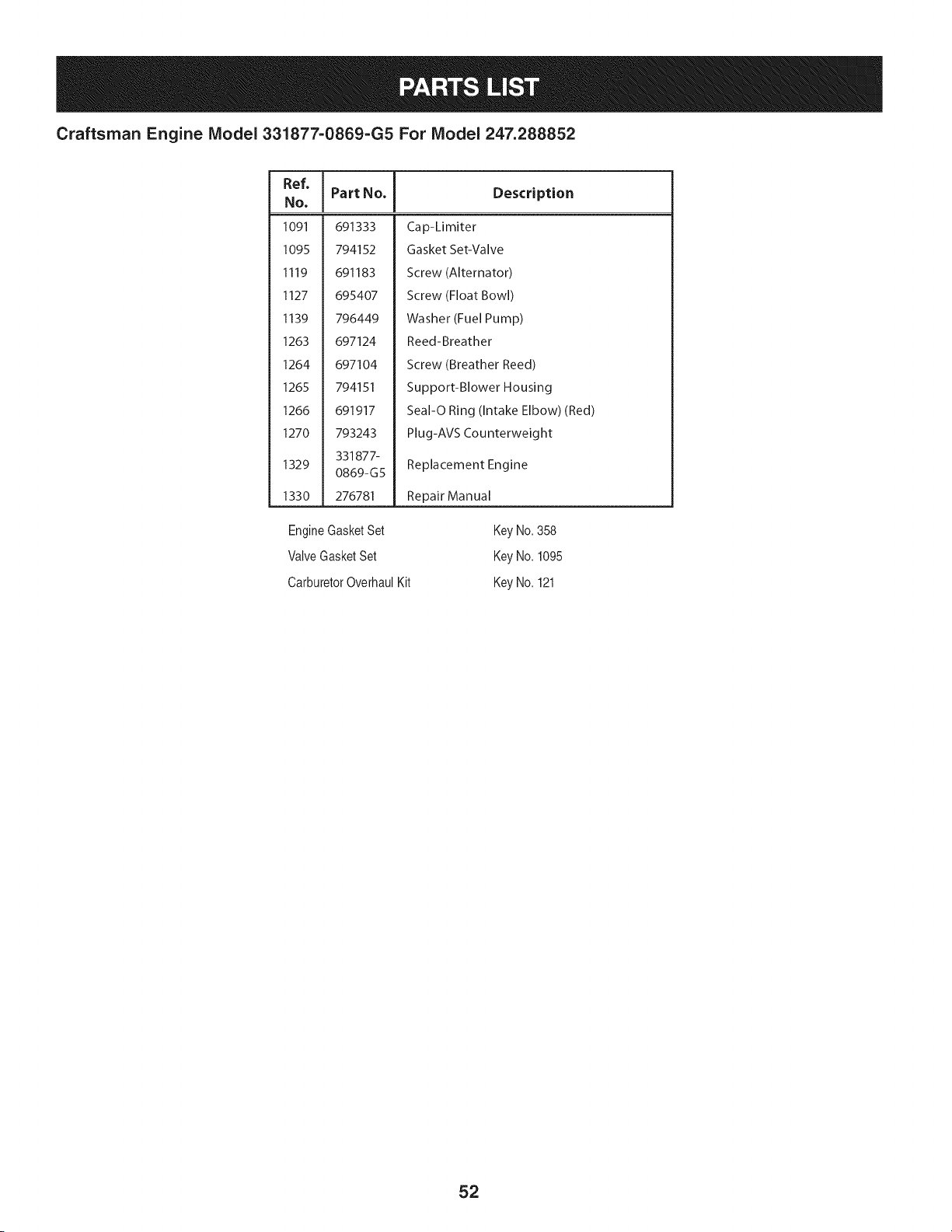
Craftsman Engine Model 331877=0869=G5 For Model 247.288852
Ref,
No.
1091 691333
1095 794152
1119 691183
1127 695407
1139 796449
1263 697124
1264 697104
1265 794151
1266 691917
1270 793243
331877-
1329
0869-G5
1330 276781
I Part No. Description
Cap-Limiter
Gasket Set-Valve
Screw (Alternator)
Screw (Float Bowl)
Washer (Fuel Pump)
Reed-Breather
Screw (Breather Reed)
Support-Blower Housing
Seal-O Ring (Intake Elbow) (Red)
Plug-AVS Counterweight
Replacement Engine
Repair Manual
EngineGasketSet
ValveGasketSet
CarburetorOverhaulKit
Key No.358
Key No.1095
Key No.121
52
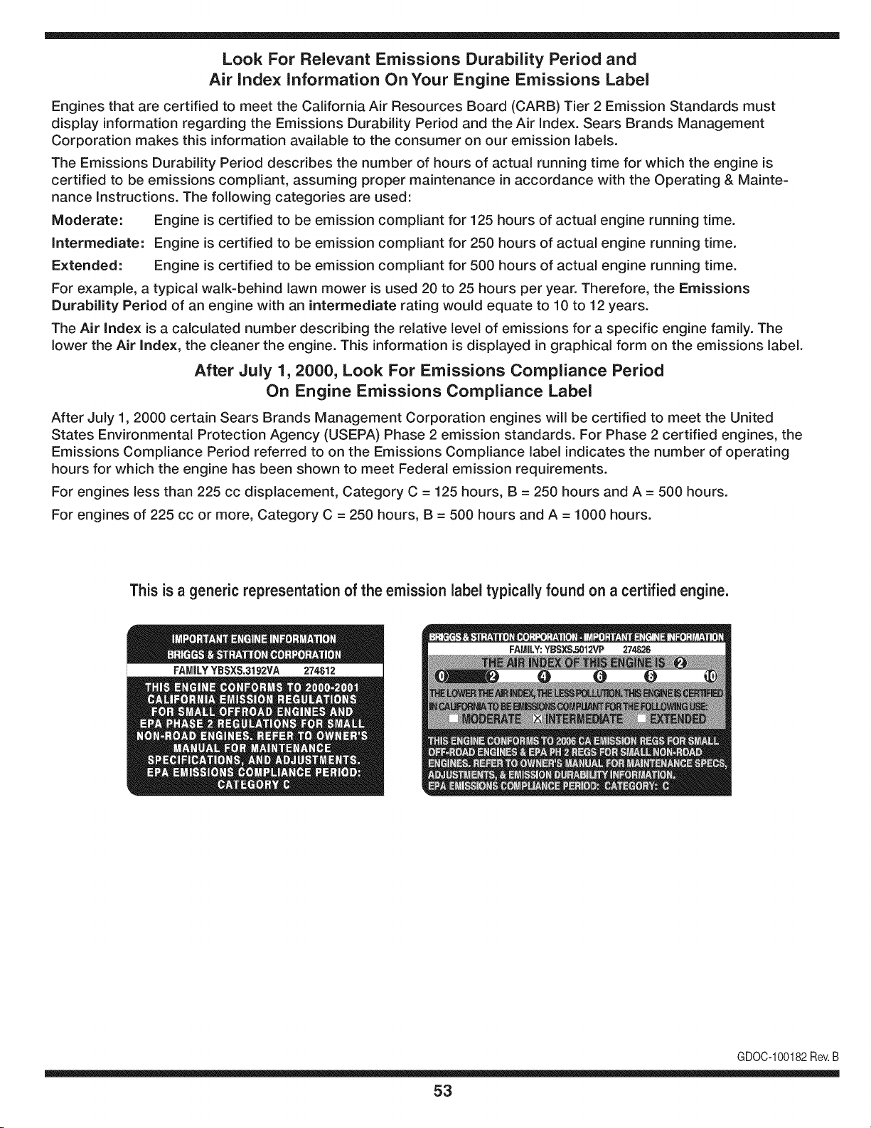
Look For Relevant Emissions Durability Period and
Air index information On Your Engine Emissions Label
Engines that are certified to meet the California Air Resources Board (CARB) Tier 2 Emission Standards must
display information regarding the Emissions Durability Period and the Air Index. Sears Brands Management
Corporation makes this information available to the consumer on our emission labels.
The Emissions Durability Period describes the number of hours of actual running time for which the engine is
certified to be emissions compliant, assuming proper maintenance in accordance with the Operating & Mainte-
nance Instructions. The following categories are used:
Moderate: Engine is certified to be emission compliant for 125 hours of actual engine running time.
Intermediate: Engine is certified to be emission compliant for 250 hours of actual engine running time.
Extended: Engine is certified to be emission compliant for 500 hours of actual engine running time.
For example, a typical walk-behind lawn mower is used 20 to 25 hours per year. Therefore, the Emissions
Durability Period of an engine with an intermediate rating would equate to 10 to 12 years.
The Air index is a calculated number describing the relative level of emissions for a specific engine family. The
lower the Air Index, the cleaner the engine. This information is displayed in graphical form on the emissions label.
After July 1,2000, Look For Emissions Compliance Period
On Engine Emissions Compliance Label
After July 1, 2000 certain Sears Brands Management Corporation engines will be certified to meet the United
States Environmental Protection Agency (USEPA) Phase 2 emission standards. For Phase 2 certified engines, the
Emissions Compliance Period referred to on the Emissions Compliance label indicates the number of operating
hours for which the engine has been shown to meet Federal emission requirements.
For engines less than 225 cc displacement, Category C = 125 hours, B = 250 hours and A = 500 hours.
For engines of 225 cc or more, Category C = 250 hours, B = 500 hours and A = 1000 hours.
This is a generic representation of the emission label typically found on a certified engine.
FAMILYYBSXS.3192VA 274812
GDOC-100182Rev.B
53
(Thispageapplicablein the U.S.A.and Canadaonly.)
Sears Brands Management Corporation (Sears), the California Air Resources Board (CARD)
and the United States Environmental Protection Agency (U.S. EPA)
Emission Control System Warranty Statement (Owner's Defect Warranty Rights and Obligations)
EMISSIONCONTROLWARRANTYCOVERAGEISAPPLICABLETOCERTI-
FIEDENGINESPURCHASEDIN CALIFORNIAIN 1995ANDTHEREAF-
TER,WHICHARE USEDINCALIFORNIA,ANDTO CERTIFIEDMODEL
California and United States Emission
The CaliforniaAir ResourcesBoard(CARD),U.S.EPAand Searsare pleased
to explainthe EmissionControlSystemWarrantyon your modelyear2000and
latersmalloff-roadengine(SORE).In California,newsmall off-roadengines
mustbe designed,builtand equippedto meetthe State'sstringentanti-smog
standards.Elsewherein the UnitedStates, newnon-road,spark-ignition
enginescertifiedfor modelyear 1997and latermustmeetsimilarstandardsset
forth bythe U.S.EPA.Sears mustwarrantthe emissioncontrolsystemon your
YEAR 1997AND LATERENGINESWHICHARE PURCHASEDAND USED
ELSEWHEREIN THE UNITEDSTATES(ANDAFTERJANUARY1,2001 IN
CANADA).
Control Defects Warranty Statement
enginefor theperiodsoftime listedbelow,providedtherehas been noabuse,
neglector impropermaintenanceof your smalloff-roadengine.Youremis-
sion controlsystemincludespartssuch as the carburetor,air cleaner,ignition
system,mufflerand catalyticconverter.Also includedmay be connectorsand
otheremissionrelatedassemblies.Wherea warrantableconditionexists,Sears
will repairyour smalloff-roadengineat no costto you includingdiagnosis,parts
and labor.
Sears Emission Control Defects Warranty Coverage
Smalloff-roadenginesarewarrantedrelativeto emissioncontrolpartsdefects
fora periodof one year,subjectto provisionsset forth below.Ifany covered
Owner's Warranty
Asthe smalloff-roadengine owner,you are responsiblefor the performanceof
therequiredmaintenancelistedin yourOperatingand MaintenanceInstruc-
tions.Searsrecommendsthatyou retain all yourreceiptscoveringmaintenance
on yoursmalloff-roadengine,but Sears cannotdenywarrantysolelyfor the
lackof receiptsorfor yourfailureto ensurethe performanceof all scheduled
maintenance.As the smalloff-roadengineowner,you shouldhoweverbe
awarethat Searsmaydenyyou warrantycoverageif your smalloff-roadengine
ora part hasfaileddueto abuse,neglect,impropermaintenanceor unap-
parton yourengineis defective,the part willbe repairedorreplacedbySears.
Responsibilities
provedmodifications.Youare responsiblefor presentingyour smalloff-road
engineto an AuthorizedSearsServiceDealeras soonas a problemexists.The
undisputedwarrantyrepairsshouldbe completedina reasonableamountof
time,notto exceed30days. Ifyou haveanyquestionsregardingyourwarranty
rightsand responsibilities,you shouldcontacta SearsService Representative
at 1-800-469-4663.The emissionwarrantyis a defectswarranty.Defectsare
judgedon normalengineperformance.The warrantyis not relatedto an in-use
emissiontest.
Sears Emission Control Defects Warranty Provisions
ThefollowingarespecificprovisionsrelativetoyourEmissionControlDefectsWarrantyCoverage.ItisinadditiontotheSearsenginewarrantyfornon-regulated
enginesfound in theOperatingand MaintenanceInstructions.
1. WarrantedParts
Coverageunderthis warrantyextendsonly to the parts listedbelow (the
emissioncontrolsystemsparts)to the extentthese partswere presenton
theengine purchased.
a. FuelMeteringSystem
• Cold start enrichmentsystem
• Carburetorand internalparts
• FuelPump
b. Air lnduction System
• Air cleaner
• Intakemanifold
c. IgnitionSystem
• Spark plug(s)
• Magnetoignitionsystem
d. CatalystSystem
• Catalyticconverter
• Exhaustmanifold
• Air injectionsystemor pulsevalve
e. MiscellaneousItemsUsedin AboveSystems
• Vacuum,temperature,position,timesensitivevalves
andswitches
• Connectorsandassemblies
2. Lengthof Coverage
Searswarrantsto the initialownerand eachsubsequentpurchaserthat
theWarrantedPartsshallbefree from defects in materialsandworkman-
shipwhich causedthefailure of the WarrantedPartsfor a periodof one
yearfrom the datethe engineis deliveredto a retailpurchaser.
3. NoCharge
Repairor replacementof anyWarrantedPartwill be performedat no
chargeto the owner,includingdiagnosticlabor whichleadsto the
determinationthata WarrantedPartis defective,ifthe diagnosticworkis
performedat an AuthorizedSearsServiceDealer.For emissionswarranty
servicecontact yournearestAuthorizedSears ServiceDealeras listed in
the "YellowPages"under"Engines,Gasoline,""GasolineEngines,""Lawn
Mowers,"or similarcategory.
4. Claimsand CoverageExclusions
Warrantyclaimsshall be filed in accordancewiththe provisionsof the
Sears EngineWarrantyPolicy.Warrantycoverageshall be excludedfor
failuresof WarrantedPartswhichare notoriginal Sears partsor because
of abuse,neglector impropermaintenanceas setforth inthe Sears
EngineWarrantyPolicy.Searsis notliableto coverfailuresof Warranted
Partscausedby the use of add-on, non-original,or modifiedparts.
5. Maintenance
Any WarrantedPart whichis notscheduledfor replacementas required
maintenanceor whichis scheduledonly for regularinspectionto the effect
of "repairor replaceas necessary"shallbe warrantedas to defectsfor the
warrantyperiod.Any WarrantedPartwhich is scheduledfor replacement
as requiredmaintenanceshallbe warrantedas to defectsonly forthe
periodof time upto the first scheduledreplacementfor that part. Any
replacementpart that is equivalentin performanceand durabilitymay
be usedin the performanceof any maintenanceor repairs.The owneris
responsibleforthe performanceof all requiredmaintenance,as definedin
the SearsOperatingand MaintenanceInstructions.
6. ConsequentialCoverage
Coveragehereundershallextendto thefailure of any engine components
caused bythe failureof any WarrantedPartstill underwarranty.
Inthe USAandCanada,a 24 hour hot line, 1-800-469-4663,has a menu of pre-recordedmessagesofferingyou enginemaintenanceinformation.
GDOC-100188Rev.B
54
FEDERAL and/or CALIFORNIA EMISSION CONTROL WARRANTY STATEMENT
YOUR WARRANTY RIGHTS AND OBLIGATIONS
MTDConsumerGroupInc,the UnitedStatesEnvironmentalProtectionAgency (EPA),and, forthose productscertifiedfor sale in the stateof California,the
CaliforniaAir ResourcesBoard(CARB)are pleasedto explainthe emission(evaporativeand/or exhaust)controlsystem(ECS) warrantyon youroutdoor 2006
andlater smalloff-roadspark-ignitedengineandequipment(outdoorequipmentengine)In California,new outdoorequipmentengines mustbe designed,built and
equippedto meetthe State'sstringentanti-smogstandards(in otherstates, 1997andlater modelyear equipmentmustbe designed,built, and equippedto meet
theU.S. EPAsmalloff-road, sparkignitionengine regulations.MTDConsumerGroupInc mustwarrantthe ECSon your outdoorequipmentenginefor the period of
timelisted belowprovidedthere has been no abuse,neglector impropermaintenanceof outdoor equipmentengine.
Your ECSmay includeparts such as thecarburetor,fuel-injectionsystem,the ignitionsystem,catalyticconverter,fuel tanks,fuel lines,fuel caps,valves,canisters,
filters,vaporhoses,clamps,connectors,andotherassociatedemission-relatedcomponents.
Wherea warrantableconditionexists, MTDConsumerGroupIncwill repairyouroutdoor equipmentengineat no cost to you includingdiagnosis,parts and labor.
MANUFACTURER'S WARRANTY COVERAGE:
Thisemissioncontrolsystemis warrantedfor two years. If any emission-relatedpart on your outdoorequipmentengineis defective,the part will be repairedor
replacedby MTDCONSUMERGROUPINC.
OWNER'S WARRANTY RESPONSIBILITIES:
Asthe outdoorequipmentengineowner,you are responsiblefor performanceof the requiredmaintenancelisted inyour owner'smanual.MTDConsumerGroup
Inc recommendsthat you retain all receiptscoveringmaintenanceon youroutdoorequipmentengine,butMTDConsumerGroupInc cannotdeny warrantysolely
forthe lackof receipts.
Asthe outdoorequipmentengineowner,you shouldhoweverbe awarethat MTDConsumerGroupInc may denyyou warrantycoverageif your outdoorequipment
engineor a part has faileddue to abuse, neglect,or impropermaintenanceor unapprovedmodifications.
Youare responsiblefor presentingyouroutdoorequipmentengineto MTDConsumerGroupInc's distributioncenterorservicecenteras soon asthe problem
exists.The warrantyrepairsshouldbe completedin a reasonableamountof time, not to exceed30 days.If you havea questionregardingyour warrantycoverage,
you shouldcontactthe MTDConsumerGroup IncService Departmentat 1-800-800-7310orvia email at http://support.mtdproducts.com
GENERAL EMISSIONS WARRANTY COVERAGE:
MTDConsumerGroupIncwarrantsto the ultimatepurchaserand eachsubsequentpurchaserthat the outdoorequipmentengineis: Designed,built and equipped
so asto conformwithall applicableregulations;and freefrom defects in materialsand workmanshipthatcausethe failureof a warrantedpart to be identicalin all
materialrespectsto that part as describedin MTDConsumerGroup Inc'sapplicationfor certification.
The warrantyperiod beginson the date the outdoorequipmentengineis deliveredto an ultimatepurchaserorfirst placedinto service.The warrantyperiodis two
years.
Subjectto certainconditionsand exclusionsasstated below,the warrantyon emission-relatedparts is asfollows:
1. Any warrantedpart that is notscheduledfor replacementas requiredmaintenancein thewritten instructionssupplied,is warrantedforthe warrantyperiod
statedabove. Ifthe part fails duringthe periodof warrantycoverage,thepart will be repairedor replacedbyMTDConsumerGroupInc accordingto subsection
(4) below. Anysuch part repairedor replacedunderwarrantywillbe warrantedfor the remainderof the period.
2. Any warrantedpart that is scheduledonly for regularinspectionin the writteninstructionssupplied is warrantedforthe warrantyperiodstatedabove.Any such
part repairedor replacedunderwarrantywill be warrantedforthe remainingwarrantyperiod.
3. Any warrantedpart that is scheduledfor replacementas requiredmaintenancein the written instructionssuppliedis warrantedfor the periodof time beforethe
first scheduledreplacementdatefor that part. If the partfails beforethe first scheduledreplacement,the part will berepairedorreplacedby MTDConsumer
GroupInc accordingto subsection(4) below.Any such part repairedor replacedunderwarrantywill be warrantedfor the remainderof the period prior to the
first scheduledreplacementpointfor the part.
4. Repairor replacementof any warrantedpart underthe warrantyprovisionshereinmustbe performedat a warrantystationat no chargeto the owner.
5. Notwithstandingthe provisionsherein,warrantyservicesor repairswill be providedat all of our distributioncentersthatare franchisedto servicethe subject
enginesor equipment.
6. The outdoorequipmentengine ownerwill notbe chargedfor diagnostic laborthat is directlyassociatedwithdiagnosisof a defective,emission-relatedwar-
rantedpart, providedthat suchdiagnosticwork is performedat a warrantystation.
7. MTDConsumerGroupInc is liablefor damagesto otherengineor equipmentcomponentsproximatelycausedby a failure underwarrantyof any warranted
part.
8. Throughoutthe off-roadengineand equipmentwarrantyperiodstatedabove, MTDConsumerGroupInc will maintaina supply of warrantedparts sufficientto
meetthe expecteddemandfor such parts.
9. Any replacementpart maybe usedinthe performanceof any warrantymaintenanceor repairsand mustbe providedwithoutchargeto the owner.Suchusewill
notreducethe warrantyobligationsof MTDConsumerGroupInc.
10.Add-onor modifiedpartsthat are not exemptedbythe Air ResourcesBoardmay not beused.The use of any non-exemptedadd-on or modifiedparts by the
ultimatepurchaserwill be groundsfor disallowinga warrantyclaims. MTDConsumerGroup Incwill not be liable to warrantfailuresof warrantedparts caused
bythe use of a non-exemptedadd-onor modifiedpart.
WARRANTED PARTS:
The repairor replacementof any warrantedpart otherwiseeligiblefor warrantycoveragemay be excludedfrom such warrantycoverageif MTDConsumerGroup
Inc demonstratesthatthe outdoor equipmentengine has beenabused,neglected,orimproperlymaintained,and that suchabuse, neglect,or impropermainte-
nancewasthe direct causeof the needfor repairor replacementof the part.That notwithstanding,any adjustmentof a componentthat hasa factory installed,
andproperlyoperating,adjustmentlimitingdevice is still eligible for warrantycoverage.Further,the coverageunderthis warrantyextendsonly to partsthat were
presenton the off-roadengineand equipmentpurchased.
Thefollowing emissionwarrantypartsare covered(if applicable):
(1) FuelMeteringSystem
• Cold start enrichmentsystem(softchoke)
• Carburetorand internalparts (or fuel injectionsystem)
• Fuelpump
• Fueltank
(2) Air InductionSystem
• Air cleaner
• Intakemanifold
(3) IgnitionSystem
• Spark plug(s)
• Magnetoignitionsystem
(4) ExhaustSystem
• Catalyticconverter
• SAI (Reed valve)
(5) MiscellaneousItemsUsedin AboveSystem
• Vacuum,temperature,position,timesensitivevalvesand switches
• Connectorsandassemblies
(6) EvaporativeControl
• Fuelhose
• Fuelhoseclamps
• Tetheredfuel cap
• Carboncanister
• Vapor lines
GDOC-100223Rev.A

Congratulations on making a smart purchase. Your new Craftsman® product is designed and
manufactured for years of dependable operation. But like all products, it may require repair
from time to time. That's when having a Repair Protection Agreement can save you money and
aggravation.
Here's what the Repair Protection Agreement* includes:
[] Expert service by our 10,000 professional repair specialists
[] Unlimited service and no charge for parts and labor on all covered repairs
[] Product replacement up to $1500 if your covered product can't be fixed
[] Discount of 25% from regular price of service and related installed parts not covered by the
agreement; also, 25% off regular price of preventive maintenance check
[] Fast help by phone - we call it Rapid Resolution - phone support from a Sears representative.
Think of us as a "talking owner's manual."
Once you purchase the Repair Protection Agreement, a simple phone call is all that it takes for you
to schedule service. You can call anytime day or night, or schedule a service appointment online.
The Repair Protection Agreement is a risk-free purchase. If you cancel for any reason during the
product warranty period, we will provide a full refund. Or, a prorated refund anytime after the
product warranty period expires. Purchase your Repair Protection Agreement today!
Some limitations and exclusions apply. For prices and additional information in the U.S.A.
call 1=800=827=6655.
*Coverage in Canada varies on some items. For full details call Sears Canada at 1=800=361=
6665.
Sears Installation Service
For Sears professional installation of home appliances, garage door openers, water heaters, and
other major home items, in the U.S.A. or Canada call 1=800=4=MY=HOME®.
57
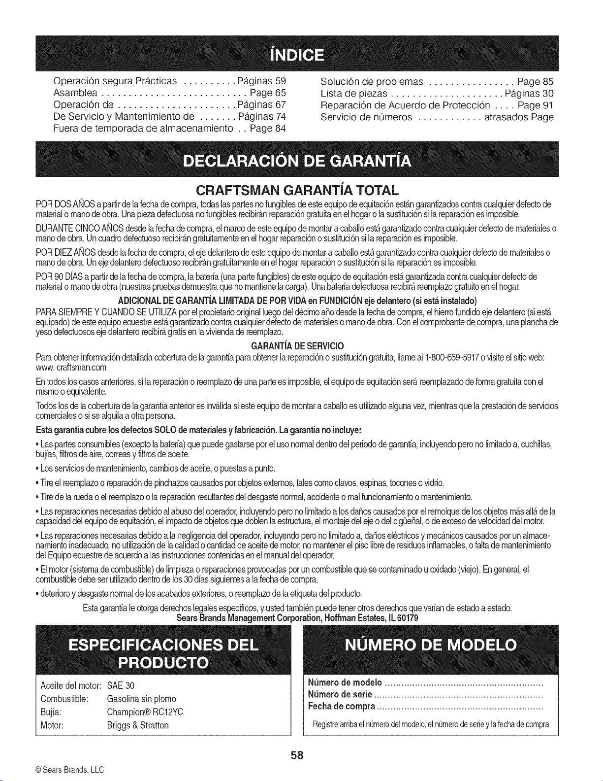
Operaci6n segura Pr,_cticas .......... Paginas 59 Soluci6n de problemas ................ Page 85
Asamblea ........................... Page 65 Lista de piezas ..................... Paginas 30
Operaci6n de ...................... Paginas 67 Reparaci6n de Acuerdo de Protecci6n .... Page 91
De Servicio y Mantenimiento de ....... Paginas 74 Servicio de nOmeros ............ atrasados Page
Fuera de temporada de almacenamiento .. Page 84
CRAFTSMAN GARANTiA TOTAL
PORDOSANOSapartrde la fechade cornpra,todaslaspartesnofungiblesdeesteequipodeequitaci6nest_ngarantizadoscontracualquierdefectode
materialornanodeobra.Unapiezadefectuosanofungiblesrecibir_.nreparaci6ngratuitaenel hogarolasustituci6nsilareparaci6nesirnposible.
DURANTECINCOANOSdesdela fechadecornpra,el marcode esteequipodernontara cabaloest_garantizadocontracualquierdefectode rnaterialeso
rnanodeobra.Uncuadrodefectuosorecibir_ngratuitarnenteenel hogarreparaci6no sustituci6nsila reparaci6nes irnposible.
PORDIEZANOSdesdelafechadecornpra,elejedelanterodeesteequipodernontaracabaloest_garantizadocontracualquierdefectodernaterialeso
rnanodeobra.Unejedelanterodefectuosorecibir_ngratuitarnenteenelhogarreparacbnosustitucbnsi la reparacbnes irnposible.
POR90DfASa partrde lafechadecornpra,labateria(unapartefungibles)de esteequipode equitaci6nest_garantizadacontracualquierdefectode
materialornanodeobra(nuestraspruebasdernuestraquenornantienelacarga).Unabateriadefectuosarecibir_,reernplazogratuitoenel hogar.
ADICIONALDEGARANTiALIMITADADEPORVIDAen FUNDICKSNejedelantero(si est_instalado)
PARASIEMPREY CUANDOSE UTILIZAporelpropietariooriginalluegodeld_cirnoaio desdela fechade cornpra,el hierrofundidoejedelantero(siest£
equipado)deesteequipoecuestreest_garantizadocontracualquierdefectodernaterialeso rnanodeobra.Conel cornprobantedecornpra,unaplanchade
yesodefectuososejedelanterorecibir_gratisenlaviviendadereernplazo.
GARANTiADESERViClO
Paraobtenerinformaci6ndetaladacoberturade lagarantaparaobtenerlareparaci6no sustituci6ngratuita,lameal 1-800-659-5917o visiteelsitioweb:
www.craftsman.corn
Entodosloscasosanteriores,silareparaci6no reernplazode unaparteesirnposible,elequipodeequitaci6nser_.reernplazadodeforrnagratuitaconel
rnisrnoo equivalente.
Todoslosdela coberturadela garantaanterioresinv&lidasiesteequipodernontara cabaloesutlizadoalgunavez,rnientrasquelaprestaci6nde servicios
cornercialeso si sealqulaa otrapersona.
Estagaranta cubrelosdefectosSOLOde materialesy fabricaci6n.Lagaranta noincluye:
• Laspartesconsurnibles(exceptolabateria)quepuedegastarseporel usonormaldentrodelperiododegaranta,induyendoperonolrnitadoa,cuchilas,
bujias,fltrosdeaire,correasy fltrosdeaceite.
• Losserviciosde rnantenirniento,carnbiosdeaceite,o puestasapunto.
•Tireel reernplazoo reparaci6nde pinchazoscausadospotobjetosexternos,talescornoclavos,espinas,toconeso vidrio.
•Tiredelaruedaoelreernplazoolareparaci6nresutantesdeldesgastenormal,accidenteo rnalfuncionarnientoornantenirniento.
• Lasreparacionesnecesariasdebidoalabusodel operador,incluyendoperonolrnitadoa losdaBoscausadosporelrernolquede losobjetosrn_.sall_.dela
capacidaddelequipodeequitaci6n,elirnpactode objetosquedoblenlaestructura,elrnontajedelejeo delcigieBal,o deexcesodevelocidaddelmotor.
• Lasreparacionesnecesariasdebidoalanegligenciadel operador,induyendoperonoIrnitadoa, daios el6ctricosy rnecanicoscausadosporunalrnace-
narnientoinadecuado,no utlizaci6ndelacalidado cantidadde aceitede motor,nornantenerelpisolibrede residuosintarnables,o faltade rnantenirniento
delEquipoecuestrede acuerdoalas instruccionescontenidasenelmanualdeloperador.
• Elmotor(sisternadecombustible)delirnpiezao reparacionesprovocadasporuncombustiblequesecontarninadou oxidado(viejo).Engeneral,el
combustibledebeserutlizadodentrode los30 diassiguientesa lafechadecornpra.
• deterioroy desgastenormalde losacabadosexteriores,o reernplazode laetiquetadel producto.
Estagarantialeotorgaderechoslegalesespecificos,y ustedtarnbi6npuedetenerotrosderechosquevariande estadoa estado.
SearsBrandsManagementCorporation,HoffmanEstates,IL 60179
Aceitedel motor: SAE30
Combustible: Gasolna sinpJorno
Bujia: Champion@RC12YC
Motor: Briggs& Stratton
NSrnerode rnodelo ..........................................................
N_mero de serie ..............................................................
Fechade compra .............................................................
RegistrearribaelnQmerodelmodelo,elnQmerodeserieylafechadecompra
© Sears Brands,LLC
58
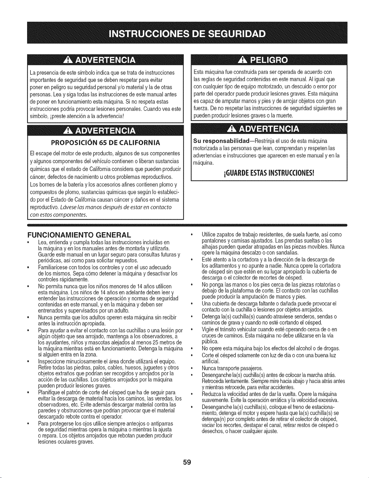
Lapresenciade este sirnboloindicaque setratade instrucciones
irnportantesde seguridadquese deben respetarparaevitar
poneren peligrosu seguridadpersonaly/o materialy lade otras
personas.Leay siga todaslas instruccionesdeestemanualantes
de poneren funcionarnientoesta rn_.quina.Si no respetaestas
instruccionespodriaprovocarlesionespersonales.Cuandoveaeste
sirnbolo,ipresteatenci6na la advertencia!
PROPOSICION 65 DE CALIFORNIA
Elescapedel motordeeste producto,algunosde suscornponentes
y algunoscornponentesdelvehiculocontieneno liberansustancias
quirnicasqueel estado de Californiaconsideraque puedenproducir
c_.ncer,defectosde nacirnientouotros problernasreproductivos.
Losbornesdela bateriay los accesoriosalinescontienenplornoy
cornpuestosde plorno,sustanciasquirnicasque seg_nIo estableci-
do porel Estadode Californiacausanc_.ncery da_osen el sisterna
reproductivo.Ldveselas manos despu_sde estaren contacto
con estoscomponentes.
Estarn_.quinarueconstruidaparaseroperadade acuerdocon
las reglasde seguridadcontenidasen este manual.AI igualque
concualquiertipo deequipornotorizado,undescuidoo errorpor
partedel operadorpuedeproducirlesionesgraves.Estarn_.quina
es capazde arnputarrnanosy piesy dearrojarobjetoscon gran
fuerza.Deno respetarlas instruccionesde seguridadsiguientesse
puedenproducirlesionesgraveso la rnuerte.
Su responsabilidad--Restrinja el usode esta rn_.quina
rnotorizadaalas personasque lean,cornprendany respetenlas
advertenciase instruccionesqueaparecenen estemanualyen la
rn_.quina.
iGUARDEESTASINSTRUCCIONES!
FUNCIONAMIENTO GENERAL
• Lea,entienday curnplatodaslas instruccionesincluidasen
la rn_.quinayen los rnanualesantes de rnontarlay utilizarla.
Guardeestemanualen un lugarseguroparaconsultasfuturasy
peri6dicas,asi cornoparasolicitarrepuestos.
• Farniliaricesecontodoslos controlesy con el usoadecuado
delos rnisrnos.Sepa c6rnodetenerlarn_.quinay desactivarlos
controlesr_.pidarnente.
• No perrnitanuncaque los ni_osrnenoresde 14a_osutilicen
estarn_.quina.Los ni_osde 14a_osen adelantedebenleer y
entenderlas instruccionesde operaci6ny norrnasdeseguridad
contenidaseneste manual,yen la rn_.quinay debenser
entrenadosy supervisadospor unadulto.
• Nuncaperrnitaquelos adultosoperenesta rn_.quinasin recibir
antesla instrucci6napropiada.
• Paraayudara evitar el contactocon las cuchillaso una lesi6npor
algQnobjetoque sea arrojado,rnantengaa los observadores,a
los ayudantes,ni_osy rnascotasalejadosal rnenos25 metrosde
la rn_.quinarnientrasest,.en funcionarniento.Detengala rn_.quina
si alguienentraen la zona.
• Inspeccionerninuciosarnenteel Areadondeutilizar_,el equipo.
Retiretodaslas piedras,palos,cables,huesos,juguetesy otros
objetosextra_osquepodrianser recogidosy arrojadospor la
acci6nde las cuchillas.Losobjetosarrojadospor la rn_.quina
puedenproducirlesionesgraves.
• Planifiqueel patr6ndecortedelc_spedque hade seguirpara
evitarla descargade materialhacialoscarninos,las veredas,los
observadores,etc.Eviteadern_.sdescargarmaterialcontralas
paredesy obstruccionesque podrianprovocarqueel material
descargadorebotecontrael operador.
• Paraprotegerselos ojos utilicesiernpreanteojoso antiparras
deseguridadrnientrasopera la rn_.quinao rnientrasla ajusta
o repara.Losobjetosarrojadosque rebotanpuedenproducir
lesionesocularesgraves.
• Utilicezapatosde trabajoresistentes,desuelafuerte,asi corno
pantalonesy carnisasajustados.Las prendassueltaso las
alhajaspuedenquedaratrapadasenlas piezasrnovibles.Nunca
operela rn_.quinadescalzoo con sandalias.
• Est_atentoa la cortadoray a la direcci6nde la descargade
losaditarnentosy noapuntea nadie.Nuncaoperelacortadora
de c_spedsin queest_nen su lugarapropiadola cubiertade
descargao elcolectorde recortesdecesped.
• Nopongalasrnanoso lospies cercade las piezasrotatoriaso
debajode la plataforrnadecorte. Elcontactocon las cuchillas
puedeproducirla arnputaci6ndernanosy pies.
• Unacubiertade descargafaltanteo da_adapuedeprovocarel
contactocon lacuchillao lesionespot objetosarrojados.
• Detengala(s)cuchilla(s)cuandoatraviesesenderos,sendaso
carninosde gravay cuandono est_cortandoel cesped.
• Vigileel tr_.nsitovehicularcuandoest_operandocercadeo en
crucesde carninos.Estarn_.quinanodebeutilizarseen la via
pQblica.
• Noopereestarn_.quinabajolosefectosdelalcoholode drogas.
• Corteel cespedsolarnentecon luzdedia o conunabuenaluz
artificial.
• Nuncatransportepasajeros.
• Desenganchela(s)cuchilla(s)antesde colocarla rnarchaatr_.s.
Retrocedalentarnente.Siernpremirehaciaabajoy haciaatr_.santes
y rnientrasretrocede,paraevitaraccidentes.
• Reduzcala velocidadantesdedarlavuelta.Operelarn_.quina
suavernente.Evitelaoperaci6nerr_.ticay la velocidadexcesiva.
• Desenganchela(s)cuchilla(s),coloqueel frenodeestaciona-
rniento,detengaelmotory esperehastaque la(s)cuchilla(s)se
detenga(n)porcornpletoantesderetirarelcolectordec_sped,
vaciarlos recortes,destaparelcanal,retirarrestosde cespedo
desechos,o hacercualquierajuste.
59
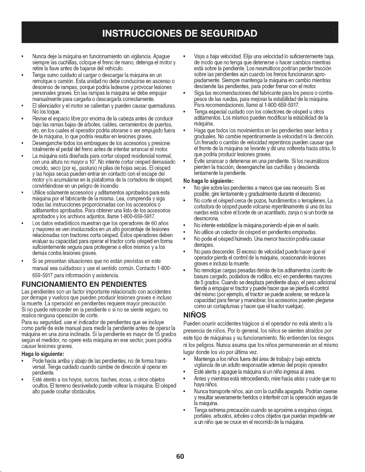
• Nuncadejelarn_.quinaen funcionarnientosinvigilancia.Apague
siernprelascuchillas,coloqueel frenodernano,detengael motory
retirela Ilaveantesde bajarsedelvehiculo.
• Tengasurnocuidadoal cargaro descargarla rn_.quinaen un
rernolqueocarni6n.Estaunidadno debeconducirseenascensoo
descensoderarnpas,porquepodrialadearsey provocarlesiones
personalesgraves.Enlas rarnpasla rn_.quinasedebeernpujar
rnanualrnenteparacargarlao descargarlacorrectarnente.
• Elsilenciadory el motorse calientany puedencausarquernaduras.
Nolos toque.
• Reviseel espaciolibrepot encirnade la cabezaantesde conducir
bajolas rarnasbajasde_.rboles,cables,cerrarnientosde puertas,
etc.en loscualeseloperadorpodriaatorarseo serernpujadofuera
dela rn_.quina,Ioquepodriaresultaren lesionesgraves.
• Desenganchetodoslosernbraguesde los accesoriosy presione
totalrnenteel pedaldel frenoantesde intentararrancarel motor.
• Larn_.quinaest,.diseSadaparacortarc_spedresidencialnormal,
conuna alturano mayora 10".Nointentecortarcespeddernasiado
crecido,seco(porej.,pastura)nipilasdehojassecas.El c_sped
y las hojassecaspuedenentraren contactoconel escapedel
motory/o acurnularseen la plataforrnade lacortadorade cesped,
convirti_ndoseen unpeligrodeincendio
• Utilicesolarnenteaccesoriosy aditarnentosaprobadosparaesta
rn_.quinapot el fabricantede la rnisrna.Lea,cornprenday siga
todaslasinstruccionesproporcionadasconlosaccesorioso
aditarnentosaprobados.Paraobteneruna listade losaccesorios
aprobadosy losarchivosadjuntos,Ilarne1-800-659-5917.
• Losdatosestadsticosrnuestranquelosoperadoresde60 aSos
y rnayoresseven involucradosenunaltoporcentajede lesiones
relacionadascontractorescorta cesped.Estosoperadoresdeben
evaluarsu capacidadparaoperarel tractorcortac_spedenforrna
suficienternenteseguraparaprotegersea ellosrnisrnosy a los
dern_.scontralesionesgraves.
Si se presentansituacionesqueno est_.nprevistasen este
manualsea cuidadosoy use el sentidocornQn.Contacto1-800-
659-5917parainforrnaci6ny asistencia.
FUNCIONAiVIIENTO EN PENDIENTES
Las pendientesson unfactorirnportanterelacionadoconaccidentes
porderrapey vuelcosquepuedenproducirlesionesgravese incluso
la rnuerte.La operaci6nen pendientesrequieremayorprecauci6n.
Si nopuederetrocederen la pendienteo si no se sienteseguro,no
realiceningunaoperaci6ndecorte.
Parasu seguridad,use el indicadorde pendientesquese incluye
cornopartede este manualpara rnedirla pendienteantes de operarla
rn_.quinaen una zonainclinada.Sila pendientees mayorde 15 grados
segQnel rnedidor,no opereesta rn_.quinaenese sector,puespodria
causarlesionesgraves.
HagaIo siguiente:
• Podehaciaarribay abajode las pendientes,no de forrnatrans-
versal.Tengacuidadocuandocarnbiededirecci6nal operaren
pendiente.
• Est_atentoa loshoyos,surcos,baches,rocas,u otrosobjetos
ocultos.El terrenodesniveladopuedevoltearla rn_.quina.El cesped
altopuedeocultarobst_.culos.
Vayaa bajavelocidad.ElijaunavelocidadIosuficienternentebaja,
de rnodoque no tengaque detenerseo hacercarnbiosrnientras
est,.sobrela pendiente.Losneurn_.ticospodrianperdertracci6n
sobrelaspendientesaQncuandolosfrenosfuncionaranapro-
piadarnente.Siernprernantengalarn_.quinaen carnbiornientras
desciendelaspendientes,parapoderfrenarconel motor.
• Sigalas recornendacionesdelfabricanteparalos pesoso contra-
pesosdelas ruedas,pararnejorarla estabilidadde la rn_.quina.
Pararecornendaciones,Ilarneal 1-800-659-5917.
• Tengaespecialcuidadocon loscolectoresdecespedu otros
aditarnentos.Losrnisrnospuedenrnodificarla estabilidadde la
rn_.quina.
• Hagaquetodoslos rnovirnientosen laspendientesseanlentosy
graduales.Nocarnbierepentinarnentelavelocidadniladirecci6n.
Unfrenadoo carnbiodevelocidadrepentinospuedencausarque
el frentede la rn_.quinase levantey d_ unavolteretahaciaatr_.s,Io
quepodriaproducirlesionesgraves.
• Evitearrancaro detenerseen una pendiente.Si losneurn_.ticos
pierdenlatracci6n,desenganchelascuchillasy descienda
lentarnentela pendiente.
No hagaIo siguiente:
• Nogire sobrelas pendientesa rnenosqueseanecesario.Sies
posible,girelentarnentey gradualrnenteduranteel descenso.
• Nocorteel c_spedcercade pozos,hundirnientosoterraplenes.La
cortadoradec_spedpuedevolcarserepentinarnentesiunade las
ruedasest,.sobreelhordede unacantilado,zanjao siunhordese
desrnorona.
• Nointenteestabilizarla rn_.quinaponiendoelpieenel suelo.
• Noutiliceuncolectordecespeden pendientesernpinadas.
• Nopodeel cespedh_rnedo.Unarnenortracci6npodriacausar
derrapes.
• Noparadescender.Elexcesodevelocidadpuedehacerqueel
operadorpierdael controlde la rn_.quina,ocasionandolesiones
gravese inclusola rnuerte.
• Norernolquecargaspesadasdetr_.sde losaditarnentos(carritode
basuracargado,podadoraderodillos,etc)en pendientesrnayores
de5 grados.Cuandosedesplazapendienteabajo,el pesoadicional
tiendeaernpujareltractory puedehacerquese pierdaelcontrol
delrnisrno(porejernplo,eltractorsepuedeacelerar,se reducela
capacidadparafrenary rnaniobrar,losaccesoriospuedenplegarse
cornouncortaplurnasy hacerqueeltractorvuelque).
NINOS
Puedenocurriraccidentestr_.gicossi el operadornoest,.atentoa la
presenciade niSos.PotIo general,los niSosse sientenatraidospor
estetipo de rn_.quinasy su funcionarniento.Noentiendenlos riesgos
ni los peligros.Nuncaasurnaquelos niSosperrnanecer_.nen el rnisrno
lugardonde losvio pot Qltirnavez.
• Mantengaa losniSosfueradel_.readetrabajoy bajoestricta
vigilanciadeunadultoresponsableadern_.sdel propiooperador.
Est_alertay apaguela rn_.quinasiunniSoingresaal _.rea.
• Antesy rnientrasest,.retrocediendo,mirehaciaatr_.sy cuidequeno
hayaniSos.
NuncatransporteniSos,aQnconlacuchillaapagada.Podriancaerse
y resultarseverarnenteheridoso interferirconla operaci6nsegurade
la rn_.quina.
Tengaextrernaprecauci6ncuandoseaproxirneaesquinasciegas,
portales,arbustos,_.rbolesu otrosobjetosquepuedanirnpedirlever
a unniSoquesecruceenel recorridode la rn_.quina.
6O
• Paraevitaraccidentesal operaren rnarchaatr_.s,siernpredesengan-
chelascuchillasantesdecolocarrnarchaatr_.s.Siest,.instalado,
el"ModoPrecaucidnMarchaAtr_.s"(hojasdeoperarlarn_.quina,
rnientrasquelospaseosa la inversa)no debeutilizarsecuandohay
ni_osuotraspersonaspresentes.
• Mantengaa losni_osalejadosdelosrnotoresen rnarchao calientes.
Puedensufrirquernadurasconunsilenciadorcaliente.
• RetirelaIlavecuandodejelarn_.quinasinvigilancia,evitequeuna
personasinautorizaci6nlarnaneje.
No perrnitanuncaque los ni_osrnenoresde 14a_osutilicenesta
rn_.quina.Losni_osde 14a_osen adelantedebenleery entenderlas
instruccionesdeoperaci6ny norrnasde seguridadcontenidasen este
manual,yen la rn_.quinay debenserentrenadosy supervisadospor
unadulto.
REIVIOLQUE
• Rernolque_nicarnenteconunarn_.quinaquecuenteconun
enganchediseSadopararernolcar.Noacopleequiporernolcado
exceptoen el puntodeenganche.
• SigalasrecornendacionesdelfabricanteenIoque respectaalos
lirnitesdepesodelosequiposa rernolcary al rernolqueen pendien-
tes.Pararecornendaciones,Ilarneal 1-800-659-5917.
• Nuncaperrnitala presenciade niSosuotraspersonasdentroosobre
losequiposrernolcados.
• Enlaspendientes,el pesodelequiporernolcadopuedecausar
p_rdidadetraccidny perdidade controlde la rn_.quina.
• Siernpreuseextralaprecauci6nrernolcandoconunarn_.quina
capazde hacervueltasapretadas(p.ejpaseo"devueltacero"-enel
cortacesped).Hagaarnpliasvueltasparaevitaralgato-knifing.
• Despl_.ceselentarnentey dejedistanciaadicionalparafrenado.
• Noparadescender.
SERVIClO
Manejo seguro de la gasolina
Paraevitarlesionespersonaleso daSosrnaterialessea surnarnente
cuidadosoal rnanipularla gasolina.La gasolinaes surnarnente
infiarnabley sus vaporespuedencausarexplosiones.Se puede
lesionargravernentesi derrarnagasolinasobreustedo sobrela ropa,
ya que _stase puedeincendiar. L_.vesela piely c_.rnbiesede ropade
inrnediato.
• Utilices61olos recipientesparagasolinaautorizados.
• NuncaIlenelos recipientesen el interiorde un vehiculoo carnidn
o cajade rernolquecon recubrirnientopl_.stico.Coloquesiernpre
los recipientesen el piso y lejosdel vehiculoantes de realizarla
carga.
• Cuandoseafactible,retireel equipoa gasolinadel carni6no
rernolquey II_neloen elsuelo. Si esto no es posible,Ileneel
equipoen unrernolqueconun contenedorport_.til,en vez de
hacerlocon una boquilladispensadoradegasolina.
• Mantengala boquillade Ilenadoen contactoconel hordedel
dep6sitode combustibleo con la aberturadel recipienteen todo
rnornento,hastaterrninarlacarga. No utiliceundispositivode
boquilladeapertura/cierre.
• Apaguetodosloscigarrillos,cigarros,pipasy otrasfuentesde
cornbustidn.
• Nuncacarguecombustibleen la rn_.quinaenun espaciocerrado.
• Nuncasaquela tapadel combustibleni agreguecombustible
rnientrasel motorest,.calienteo enrnarcha.Dejequeel motor
seenfrie porIornenosdos rninutosantesde volvera cargar
combustible.
• NuncaIleneen excesoel dep6sitode combustible.Lleneel
tanqueno rn_.sde 1/2pulgadapordebajode la basedel cuello
del tap6nde carga, paradejar espacioparalaexpansi6ndel
combustible.
• Vuelvaa colocarlatapa de la gasolinay ajQstelabien.
• Lirnpieel combustibleque se hayaderrarnadosobreel motory el
equipo.Trasladelarn_.quinaa otrazona.Espere5 rninutosantes
de encenderelmotor.
• Parareducirel riesgode incendio,rnantengala rn_.quinalirnpia
de pasto,hojasy de acurnulacidnde otros residuos.Lirnpielos
derrarnesdeaceiteo combustibley saquetodos los residuos
ernbebidosde combustible.
• Nuncaguarde la rn_.quinao el recipientede combustibleen un
espaciocerradodondehayafuego,chispaso luz piloto,corno
porejernplodecalentadoresdeagua,calefactoresde arnbientes,
hornos,secadoresde ropau otrosaparatosa gas.
• Dejequela rn_.quinase enfriecincorninutospor Iornenosantes
de guardarla.
Servicio general
• Nuncaenciendael motoren espacioscerradoso en unazona
con pocaventilacidn.Elescapedel motorcontienernondxidode
carbono,ungas inodoroy letal.
• Antesdelirnpiar,repararo inspeccionarla rn_.quina,cornpruebe
que la(s)cuchilla(s)y todaslas partesen rnovirnientose hayan
detenido.Desconecteel cablede la bujfay p6ngalohaciendo
rnasacontrael motorparaevitarque se enciendaaccidental-
rnente.
• Reviseperi6dicarnenteparaasegurarseque las cuchillasse
detenganporcornpletoen aproxirnadarnentecinco(5) segundos
despu_sdeaccionarel controlde desenganchede la(s)
cuchilla(s).Si las cuchillasno se detienendentrode este lapso
de tiernpo,su unidaddeber_,ser reparadaporsu distribuidorde
servicioautorizadoMTD.
• Reviseconfrecuenciaelfuncionarnientodelsisternadefrenos
ya que est,.sujetoa desgasteporla operaci6nnormal.Ajustey
efectQernantenirnientosegQnse requiera.
61
• Reviselos pernosdemontajede la(s) cuchilla(s)y del motora
intervalosfrecuentesparaverificarque est_n bien apretados.
Adem_.s,inspeccionevisualmentela(s) cuchilla(s)en buscade
daSos(porejemplo,desgasteexcesivo,abolladuras,rajaduras,
etc.). Reemplacela(s) cuchilla(s)Qnicamentecon lascuchillas
defabricantesde equiposoriginales(O.E.M.)listadasen este
manual.Elusode piezasqueno cumplencon las especifi-
cacionesdelequipooriginal podriatenercomoresultadoun
rendimientoincorrectoy adem_.sponeren riesgola seguridad.
• Lascuchillasdelas podadorassonmuyafiladas.Envuelvala
cuchillao utiliceguantesy extremelasprecaucionescuando
efectQemantenimiento.
Mantengatodoslos pernos,tuercasy tornillosbienajustados
paraasegurarsede que la m_.quinase encuentraen condiciones
segurasde operaci6n.
• Nuncaaltereel sistemade enclavamientode seguridadni
otrosmecanismosde seguridad.Controleperiddicamenteque
funcionencorrectamente.
Despu_sdegolpearcon algQnobjetoextraSo,detengael motor,
desconecteel cablede la bujfay conecteel motora masa.
Inspeccioneminuciosamentela m_.quinaparaver si est,. daSada.
Repareel daSoantes de arrancary ufilizarla m_.quina.
Nuncatratede hacerajusteso reparacionesa la m&quina
mientrasel motorest&enmarcha.
• Loscomponentesdel colectorde c_spedy la cubiertade
descarga,estansujetosa desgastey daSosque podriandejar
expuestaspartesen movimientoo permitirque se arrojenobjetos.
Paraprotegersuseguridad,verifiquefrecuentementetodoslos
componentesy reempl_.celosinmediatamentes61ocon piezasde
los fabricantesdel equipooriginal,listadosen estemanual.Eluso
de piezasque no cumplencon las especificacionesdel equipo
originalpodriatenercomo resultadoun rendimientoincorrectoy
adem_.sponeren riesgola seguridad.
• Nocambielaconfiguraci6ndel reguladordel motorni Ioopere
a sobrevelocidad.El reguladordel motorcontrolala velocidad
m_.ximasegurade funcionamientodel motor.
• Mantengao reemplacelasefiquetasde seguridade instrucciones
segQnseanecesario.
Respetelas normasreferentesa ladisposicidncorrectay las
reglamentacionessobregasolina,aceite,etc. paraprotegerel
medicambiente.
• SegQnla Comisi6ndeSeguridadde Productosparael Consumi-
dorde los EstadosUnidos(CPSC)y laAgenciade Protecci6n
Ambientalde los EstadosUnidos(EPA),esteproductotieneuna
vida Qtilmediade siete(7)aSos,6 270 horasdefuncionamiento.
AIfinalizarla vidaQtilmedia,adquieraunam_.quinanuevao haga
inspeccionaranualmente_staSearspor uno u otrodistribuidorde
serviciosparacerciorarsedeque todos los sistemasmec_.nicos
y de seguridadfuncionancorrectamentey no tienenexcesivo
desgaste.Si no Io hace,puedenproducirseaccidentes,lesiones
o muerte.
NO MODIFIQUE EL MOTOR
Paraevitarlesionesgraveso lamuerte,nomodifiqueel motorbajo
ningunacircunstancia.Si cambialaconfiguraci6ndel reguladordel
motorel motorpuededescontrolarsey operara velocidadesinsegu-
ras.Nuncacambie la configuraci6nde f_.bricadel reguladordel motor.
AVlSO REFERIDO A EMISlONES
Losmotoresque estAncertificadosy cumplencon las regulaciones
de emisionesfederalesEPAy de CaliforniaparaSORE(Equipos
pequeSostodoterreno)estAncertificadosparaoperar congasolina
comQnsin plomoy puedenincluirlos siguientessistemasde control
de emisiones:Modificacidnde motor(EM) y catalizadorde tresvias
(TWC) siest_.nequipadosde esa manera.
GUARDACHISPAS
Estam&quinaest,.equipadacon unmotorde combusti6ninternay
nodebe ser ufilizadaen o cercade unterrenoagrestecubiertopor
bosque,malezaso hierbaexceptosi el sistemade escapedelmotor
est&equipadocon unamortiguadorde chispasque cumplacon las
leyeslocaleso estatalescorrespondientes,encasode haberlas.
Si se utiliza un amortiguadorde chispasel operadorIo debe mantener
en condicionesde usoadecuadas.Enel Estadode California las
medidasanteriormentemencionadassonexigidasporIcy (Arficulo
4442del C6digode RecursosPOblicosde California).Esposible
queexistanleyessimilaresenotros estados.Lasleyesfederalesse
aplicanen territoriosfederales.
Puedeconseguirel amortiguadorde chispasparael silenciadora
travesde su distribuidorautorizadode motoreso poni_ndoseen
contactoconel centrode servicioSears.
62
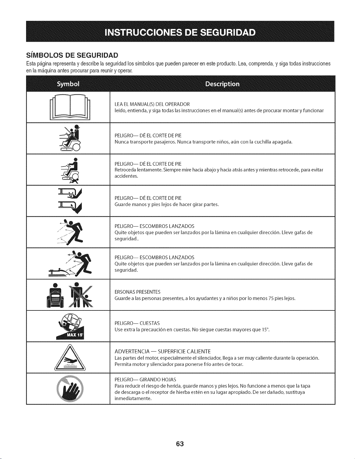
SilVlBOLOS DE SEGURIDAD
Estap&ginarepresentay describela seguridadlos simbolosquepuedenpareceren este producto.Lea,comprenda,y sigatodasinstrucciones
enla m_quinaantesprocurarpara reuniry operar.
0
J
AL
LEA EL MANUAL(S) DEL OPERADOR
leido, entienda, y siga todas las instrucciones en el manual(s) antes de procurar montar y funcionar
PELIGRO-- DE EL CORTE DE PIE
Nunca transporte pasajeros. Nunca transporte niffos, aun con la cuchilla apagada.
PELIGRO-- DIe EL CORTE DE PIE
Retroceda lentamente. Siempre mire hacia abajo y hacia atr_is antes y mientras retrocede, para evitar
accidentes.
PELIGRO-- DIe EL CORTE DE PIE
Guarde manos y pies lejos de hacer girar partes.
PELIGRO-- ESCOMBROS LANZADOS
Quite objetos que pueden set lanzados por la I_imina en cualquier direcci6n. Lleve gafas de
seguridad..
PELIGRO-- ESCOMBROS LANZADOS
Quite objetos que pueden set lanzados por la I_imina en cualquier direcci6n. Lleve gafas de
seguridad.
ERSONAS PRESENTES
Guarde a las personas presentes, a los ayudantes y a ni_os por Io menos 75 pies lejos.
PELIGRO-- CU ESTAS
Use extra la precauci6n en cuestas. No siegue cuestas mayores que 15°.
ADVERTENCIA-- SUPERFICIECALIENTE
Las partes del motor, especialmente el silenciador, Ilega a set muy caliente durante la operaci6n.
Permita motor y silenciador para ponerse frio antes de tocar.
PELIGRO-- GIRANDO HOJAS
Para reducir el riesgo de herida, guarde manos y pies lejos. No funcione a menos que la tapa
de descarga o el receptor de hierba est_n en su lugar apropiado. De set dahado, sustituya
inmediatamente.
63
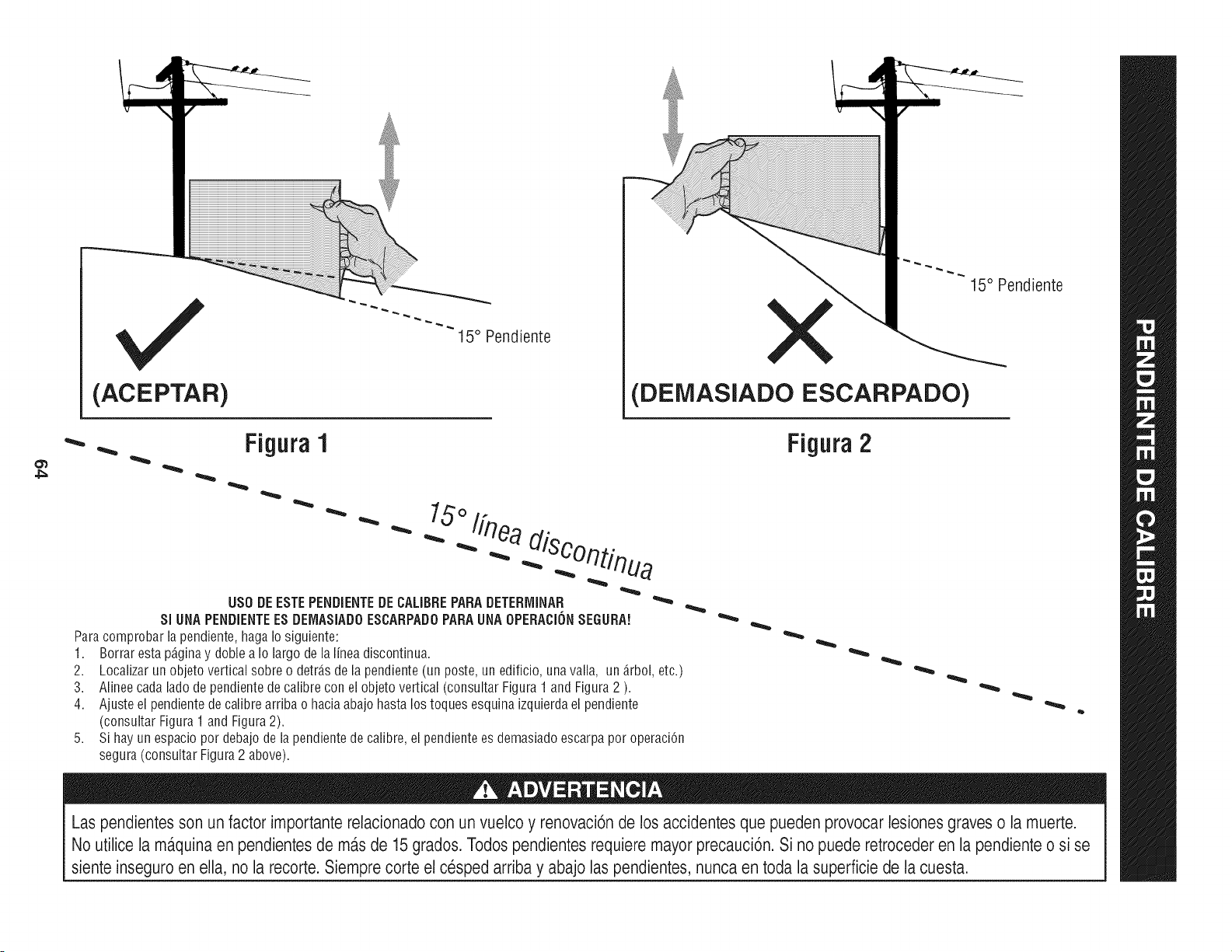
(ACEPTAR)
I5 ° Pendiente
X
(DEMASIADO ESCARPADO)
15° Pendiente
4_
• Figura1
"'"
USO DE ESTE PENDiENTE DE CALIBRE PARA DETERrvIINAR
SlUNA PENDIENTEES DEIVlASIADOESCARPADO PARA UNA OPEBACION SEGURA!
Para comprobar la pendiente, haga Io siguiente:
1. Borrar esta p_ginay doble a Io largo de la linea discontinua.
2.
3.
4.
5,
Localizar un objeto vertical sobre o detr_.sde la pendiente (un poste, un edificio, una valla, un _.rbol, etc.)
Alinee cada lado de pendiente de calibre con el objeto vertical (consultar Figura 1 and Figura 2 ).
Ajuste el pendiente de calibre arriba o hacia abajo hasta los toques esquina izquierda el pendiente
(consultar Figura 1 and Figura 2).
Si hay un espacio por debajo de la pendiente de calibre, el pendiente es demasiado escarpa por operaci6n
segura (consultar Figura 2 above).
Figura 2
Las pendientes son un factor importante relacionado con un vuelco y renovaci6nde los accidentes que pueden provocar lesiones graves o la muerte.
No utilice la ma.quinaen pendientesde ma.sde 15 grados. Todos pendientes requiere mayor precauci6n. Si no puede retroceder en la pendienteo si se
siente inseguro en ella, no la recorte. Siemprecorte el cesped arriba y abajo las pendientes, nunca en toda la superficie de la cuesta.
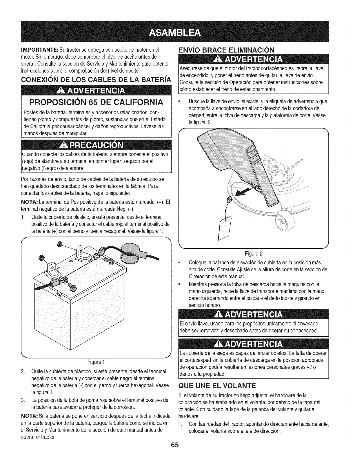
IMPORTANTE: Su tractorseentregaconaceitede motoren el
motor.Sinembargo,debe cornprobarel niveldeaceiteantes de
operar.Consultela secci6nde Servicioy Mantenirnientoparaobtener
instruccionessobrelacornprobaci6ndel nivelde aceite.
CONEXION DE LOS CABLES DE LA BATER{A
PROPOSlClON 65 DE CALiFORNiA
Postesdela bateria,terrninalesy accesoriosreladonados,con-
fienen plornoy cornpuestosde plorno,sustanciasqueen el Estado
de Californiapor causarc_.ncery daSosreproducfivos.L_.veselas
rnanosdespu_sde rnanipular.
Cuandoconecteloscablesde la bateria,siernpreconecteel posifivo
I(rojo)de alarnbrea su terminalen primerlugar,seguidopor el
pgafivo (Negro)dealarnbre.
Porrazonesde envb, tanto de cablesde la bateriade su equipose
hanquedadodesconectadode los terrninalesen laf_.brica.Para
conectarlos cablesde la bateria,hagaIo siguiente:
NOTA: La terminalde Pospositivode labateriaest,.rnarcada.(+). El
terminalnegativode la bateriaest&rnarcadaNeg.(-).
1. Quitela cubiertade pl&stico,si est&presente,desdeelterminal
positivode labateriay conectarel cablerojoal terminalpositivode
labateria(+)conel pernoy tuercahexagonal.Veaselafigura1.
f --,,
ENV{O BRACE ELllVIINACI(SN
AsegQresedequeel motordel tractorcortacespedes, retirela Ilave
de encendido,y ponerel frenoantesde quitarla Ilavedeenv[o.
IConsultela secci6nde Operaci6nparaobtenerinstruccionessobre
[c6rnoestaNecerel frenode estacionarniento.
Busquela Ilavedeenvio,siexiste,y laetiquetadeadvertenciaque
acornpaSaa encontrarseenel ladoderechode lacortadorade
cesped,entrela tolvade descargay la plataforrnade corte.Wase
la figura.2.
//
Figura1
2. Quitela cubierta de pl_.stico,si est,.presente,desdeel terminal
negativode la bateriay conectarel cable negroal terminal
negativode la bateria(-) con elpernoy tuerca hexagonal.V_ase
lafigura 1.
3. La posici6nde la botadegorna rojasobreel terminalpositivode
la bater[apara ayudara protegerde la corrosi6n.
NOTA: Si la bater[ase poneen serviciodespu_sde lafecha indicada
en lapartesuperiorde la bater[a,carguela bater[acornose indicaen
el Servicioy Mantenirnientode la secci6ndeestemanualantesde
operarel tractor.
Figura2
Coloquelapalancade elevaci6ndecubiertaen la posici6nrn_.s
altade corte.ConsulteAjustede la alturade corte en la secci6nde
Operaci6ndeestemanual.
Mientraspresionalatolvadedescargahaciala rn_.quinacon la
rnanoizquierda,retirela Ilavede transporternar[tirnoconla rnano
derechaagarrandoentreel pulgary el dedo[ndicey girandoen
sentidohorario.
ElenvioIlave,usadoparalos prop6sitosQnicarnenteel envasado,
debeser rernovidoy desechadoantesde operarsu cortacesped.
Lacubiertade la siegaes capazdelanzarobjetos.La faltade operar
el cortac_spedsin lacubiertade descargaen la posici6napropiada
de operaci6npodriaresultarenlesionespersonalesgravesy / o I
lda_osa a propedad. j
QUE UNE EL VOLANTE
Si el volantede su tractorno Ileg6adjunta,el hardwarede la
colocaci6nse ha ernbaladoenel volante,pordebajode latapa del
volante.Con cuidadola tapade la palancadelvolantey quitarel
hardware.
1. Con las ruedasdeltractor,apuntandodirectarnentehaciadelante,
colocarel volantesobreel eje de direcci6n.
65
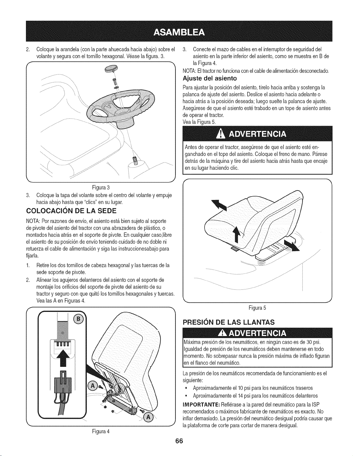
2. Coloquela arandela(con la parteahuecadahaciaabajo) sobreel
volantey seguracon el tornillohexagonal.Wase la figura.3.
f -,
Figura3
3. Coloquela tapadel volantesobreel centrodel volantey empuje
haciaabajo hastaque "clics"en su lugar.
COLOCAClON DE LA SEDE
NOTA:Porrazonesde envfo,el asientoest,. bien sujetoal soporte
depivotedel asientodel tractorcon unaabrazaderadepl_.stico,o
montadoshaciaatr_.sen elsoportede pivote.Encualquiercaso,libre
el asientode su posici6ndeenvfoteniendocuidadode no doble ni
retuerzael cablede alimentaci6ny sigalas instruccionesabajopara
fijarla.
1. Retirelos dostornillosde cabezahexagonaly lastuercasde la
sedesoportede pivote.
2. Alinearlosagujerosdelanterosdel asientoconel soportede
montajelosorificiosdelsoportede pivotedel asientode su
tractory segurocon que quit6los tornilloshexagonalesy tuercas.
Vealas A en Figuras4.
f-
Figura4
3. Conecteel rnazode cablesen el interruptorde seguridaddel
asientoen la parteinferiordel asiento,como se muestraen Bde
laFigura4.
NOTA:El tractorno funcionaconel cabledealimentaci6ndesconectado.
Ajuste del asiento
Paraajustarla posici6ndel asiento,firelohaciaarriba y sostengala
palancadeajustedel asiento.Desliceel asientohaciaadelanteo
haciaatr_.sa la posici6ndeseada;luegosueltela palancade ajuste.
AsegQresedequeel asientoest_ trabadoen un topede asientoantes
de operarel tractor.
Veala Figura5.
Antesde operarel tractor,asegQresede que el asientoest_ en-
ganchadoenel topedel asiento.Coloqueel frenode mano.P_.rese
detr_.sde la m_.quinay tire delasientohaciaatr_.shastaque encaje
en su lugarhaciendoclic.
Figura5
PFIESl0N DE LAS LLANTAS
M_.ximapresi6nde los neum_.ticos,en ning_ncasoes de30 psi.
Igualdadde presi6nde los neum_.ticosdeben mantenerseen todo
momento.Nosobrepasarnuncalapresi6nm_.ximade infiadofiguran
len e f anco de neum_.tco.
Lapresi6nde los neum_.ticosrecomendadade funcionamientoes el
siguiente:
• Aproximadamenteel 10psi para los neum_.ticostraseros
• Aproximadamenteel 14psi para los neum_.ticosdelanteros
INIPORTANTE: Refi_rasea la pareddel neum_.ticoparala ISP
recomendadoso m_.ximosfabricantede neum_.ticoses exacto.No
inflardemasiado.Lapresi6ndel neum_.ticodesigualpodriacausarque
laplataformade corteparacortarde maneradesigual.
66
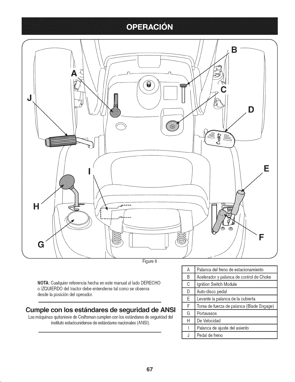
J
C
D
E
F
j
Figure6
NOTA:Cualquierreferenciahechaeneste manualal lado DERECHO
o IZQUIERDOdeltractordebe entendersetal comose observa
desdela posici6ndel operador.
Cumple con los est_ndares de seguridad de ANSI
Lasm_.quinasquitanievede Craftsmancumplenconlosest_.ndaresde seguridaddel
institutoestadounidensede est_.ndaresnacionales(ANSI).
A Palancadel frenode estacionamiento
B Aceleradory palancade control de Choke
C IgnitionSwitchModule
D Auto-discopedal
E Levantela palancade la cubierta
F Tomadefuerza de palanca(Blade Engage)
G Portavasos
H De Velocidad
I Palancade ajustedel asiento
J Pedalde freno
67
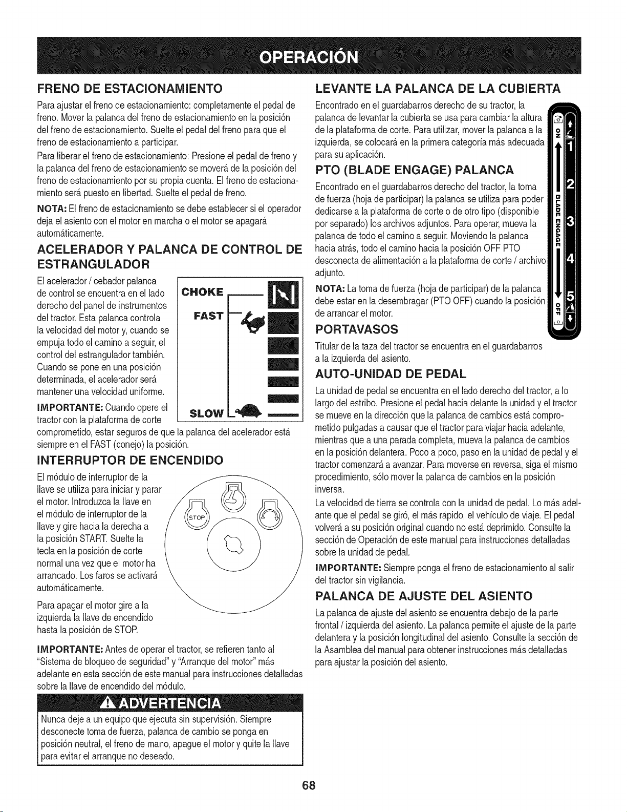
FRENO DE ESTACIONAIVllENTO
Paraajustarel frenode estacionarniento:cornpletarnenteel pedalde
freno.Moverla palancadel frenode estacionarnientoen la posici6n
delfrenode estacionarniento.Suelteel pedaldel freno paraqueel
frenode estacionarnientoa participar.
Paraliberarel frenode estacionarniento:Presioneelpedal de frenoy
la palancadelfrenode estacionarnientose rnover_,de la posici6ndel
frenode estacionarnientopor su propiacuenta.El frenode estaciona-
rnientoser_.puestoen libertad.Suelteel pedalde freno.
NOTA: El frenode estacionarnientosedebeestablecersi el operador
dejael asientocon el motorenrnarchao el motorse apagar_.
autorn_.ticarnente.
ACELERADOR Y PALANCA DE CONTROL DE
ESTRANGULADOR
Elacelerador/ cebadorpalanca
decontrol seencuentraenel lado
derechodel paneldeinstrurnentos
deltractor.Estapalancacontrola
lavelocidaddelmotory, cuandose
ernpujatodo elcarninoa seguir,el
controldelestranguladortarnbi_n.
Cuandose poneenunaposici6n
deterrninada,el aceleradorser_.
rnantenerunavelocidaduniforrne.
IMPORTANTE: Cuandoopere el
tractorcon la plataforrnadecorte
SLOW
= EE
cornprornetido,estar segurosde que la palancadelaceleradorest,.
siernpreen el FAST(conejo)la posici6n.
INTERRUPTOR DE ENCENDIDO
El rn6dulode interruptorde la
Ilavese utilizapara iniciary parar
el motor.Introduzcala Ilaveen
el rn6dulode interruptorde la
Ilavey gire haciala derechaa
la posici6nSTART.Sueltela
teclaen la posici6nde corte
normalunavez que el motorha
arrancado.Losfarosse activar_.
autorn_.ticarnente.
Paraapagarel motorgirea la
izquierdalaIlavede encendido
hastala posici6nde STOR
llVIPORTANTE: Antesde operarel tractor,se refierentantoal
"Sisternade bloqueode seguridad"y "Arranquedel motor"rn_.s
adelanteenesta secci6nde este manualpara instruccionesdetalladas
sobrela Ilavede encendidodel rn6dulo.
Nuncadejea un equipoque ejecutasin supervisi6n.Siernpre
desconectetornade fuerza,palancade carnbiose pongaen
posici6nneutral,el frenode rnano,apagueel motory quitela Ilave
paraevitarel arranqueno deseado.
LEVANTE LA PALANCA DE LA CUBIERTA
Encontradoenel guardabarrosderechode su tractor,la
palancade levantarla cubiertase usa paracarnbiarlaaltura
de la plataforrnadecorte. Parautilizar,moverla palancaa la
izquierda,secolocar_,en laprirneracategoriarn_.sadecuada
parasu aplicaci6n.
PTO (BLADE ENGAGE) PALANCA
Encontradoenel guardabarrosderechodel tractor,la torna
de fuerza(hojade participar)la palancase utilizaparapoder
dedicarsea laplataforrnade corte o de otrotipo (disponible
por separado)los archivosadjuntos.Paraoperar,rnuevala
palancade todoel carninoa seguir.Moviendola palanca
haciaatr_.s,todo elcarninohacia la posici6nOFF PTO
desconectade alirnentaci6na la plataforrnade corte/ archivo
adjunto.
NOTA: La tornade fuerza (hojade participar)de lapalanca
debeestar en la desernbragar(PTOOFF)cuandola posici6n
de arrancarel motor.
PORTAVASOS
Titularde la tazadel tractorse encuentraenel guardabarros
a la izquierdadelasiento.
AUTO-UNIDAD DE PEDAL
Launidadde pedalse encuentraenel lado derechodel tractor,a Io
largodel estribo.Presioneel pedalhaciadelantela unidady el tractor
se rnueveen la direcci6nquela palancadecarnbiosest,.cornpro-
rnetidopulgadasa causarque el tractorparaviajar haciaadelante,
rnientrasque a una paradacornpleta,rnuevala palancade carnbios
en la posici6ndelantera.Pocoa poco, pasoenla unidadde pedaly el
tractorcornenzar_,a avanzar.Pararnoverseen reversa,sigael rnisrno
procedirniento,s61omoverla palancadecarnbiosen la posici6n
inversa.
Lavelocidadde tierra se controlacon la unidadde pedal.Lorn_.sadel-
anteque el pedal se gir6,el rn_.sr_.pido,el vehiculode viaje. El pedal
volver_,a su posici6noriginalcuandonoest,. deprirnido.Consultela
secci6nde Operaci6nde este manualparainstruccionesdetalladas
sobrela unidadde pedal.
IMPORTANTE: Siernprepongael frenode estacionarnientoal salir
del tractorsinvigilancia.
PALANCA DE AJUSTE DEL ASIENTO
Lapalancade ajustedel asientose encuentradebajode la parte
frontal/izquierda delasiento.Lapalancaperrniteel ajuste de la parte
delanteray laposici6nlongitudinaldel asiento.Consultelasecci6nde
la Asarnbleadel manualparaobtenerinstruccionesrn_.sdetalladas
paraajustarla posici6ndel asiento.
68
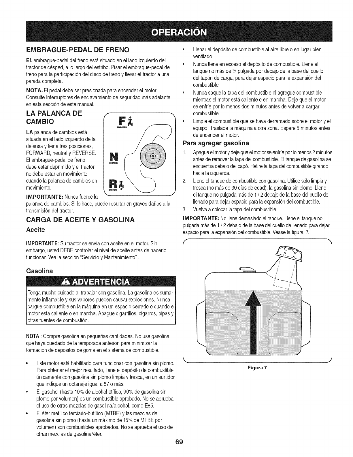
EMBRAGUE-PEDAL DE FRENO
EL ernbrague-pedaldel frenoest,. situadoen el lado izquierdodel
tractorde c_sped,a Io largo delestribo.Pisarel ernbrague-pedalde
frenopara la participaci6ndel disco de frenoy Ilevarel tractora una
paradacornpleta.
NOTA: El pedal debe ser presionadaparaencenderel motor.
ConsulteInterruptoresde enclavarnientode seguridadrn_.sadelante
enesta secci6ndeeste manual.
LA PALANCA DE f
cAMBIo F ;i;
LA palancade carnbiosest,.
situadaenel lado izquierdode la
defensay tienetresposiciones,
FORWARD,neutraly REVERSE.
Elernbrague-pedalde freno
debeestardeprirnidoy el tractor
nodebe estar en rnovirniento
cuandola palancade carnbiosen
rnovirniento.
IMPORTANTE: Nuncafuercela
palancade carnbios.Si Io hace,puede resultarengravesdaSosa la
transrnisi6ndel tractor.
CARGA DE ACEITE Y GASOLINA
Aceite
• Llenarel dep6sitode combustiblealaire libreo en lugarbien
ventilado.
• NuncaIleneen excesoel dep6sitode combustible.Lleneel
tanqueno rn_.sde 1/2pulgadapordebajode la basedel cuello
del tap6nde carga, paradejar espacioparalaexpansi6ndel
combustible.
• Nuncasaquela tapadel combustibleni agreguecombustible
rnientrasel motorest,.calienteo enrnarcha.Dejequeel motor
seenfrie porIornenosdos rninutosantesde volvera cargar
combustible.
• Lirnpieel combustibleque se hayaderrarnadosobreel motory el
equipo.Trasladelarn_.quinaa otrazona.Espere5 rninutosantes
de encenderelmotor.
Para agregar gasolina
1. Apagueel motory dejequeelmotorseenfriepot Iornenos2 rninutos
antesde removerlatapadel combustible.Eltanquede gasolinase
encuentradebajodelcap6.Retirela tapadel combustiblegirando
hacialaizquierda.
2. Lleneel tanquede combustiblecongasolina.Utilices61olirnpiay
fresca(norn_.sde 30 diasde edad),la gasolinasinplorno.Llene
el tanquenopulgadarn_.sde 1 / 2 debajode la basedelcuellode
Ilenadoparadejarespacioparala expansi6ndel combustible.
3. Vuelvaacolocarla tapadelcombustible.
IMPORTANTE: NoIlenedernasiadoeltanque.Lleneel tanqueno
pulgadarn_.sde 1/ 2 debajode la basedel cuellode Ilenadoparadejar
espacioparalaexpansi6ndel combustible.Wase lafigura.7.
IMPORTANTE:Su tractorse enviacon aceiteen el motor.Sin
embargo,usted DEBEcontrolarel nivelde aceiteantesde hacerlo
funcionar.Vealasecci6n"Servicioy Mantenirniento".
Gasolina
Tengarnuchocuidadoal trabajarcon gasolina.Lagasolinaes surna-
rnenteinfiarnabley sus vaporespuedencausarexplosiones.Nunca
carguecombustibleen la rn_.quinaenun espaciocerradoo cuandoel
motorest,.calienteo en rnarcha.Apaguecigarrillos,cigarros,pipasy
otrasfuentesde cornbusti6n.
NOTA: Cornpregasolinaen pequeSascantidades.No usegasolina
quehayaquedadode la ternporadaanterior,pararninirnizarla
forrnaci6nde dep6sitosdegornaen el sisternade combustible.
• Estemotorest,.habilitadoparafuncionarcongasolinasin plorno.
Paraobtenerel rnejorresultado,Ileneel dep6sitode combustible
Onicarnentecongasolinasin plornolirnpiay fresca,enun surtidor
queindiqueun octanajeigual a 87 o rn_.s.
• Elgasohol(hasta 10%de alcoholefilico,90% de gasolinasin
plornoporvolurnen)es un combustibleaprobado.No seaprueba
el usode otrasrnezclasde gasolina/alcohol,cornoE85.
• El_ter rnefilicoterciario-bufilico(MTBE)y las rnezclasde
gasolinasin plorno(hastaun rn_.xirnode 15%de MTBEpor
volurnen)son combustiblesaprobados.Nose apruebael uso de
otrasrnezclasdegasolina/eter.
69
Figura 7
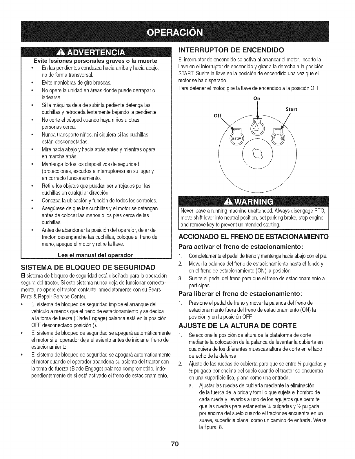
Evite lesiones personales graves o la muerte
• Enlas pendientesconduzcahaciaarriba y haciaabajo,
node forrnatransversal.
• Eviternaniobrasde girobruscas.
• No operela unidaden _.reasdonde puedederraparo
ladearse.
• Si larn_.quinadejade subirla pedientedetengalas
cuchillasy retrocedalentarnentebajandola pendiente.
• No corte el c_spedcuandohayani_osu otras
personascerca.
• Nuncatransporteni_os,ni siquierasi las cuchillas
est_.ndesconectadas.
• Mirehaciaabajoy haciaatr_.santesy rnientrasopera
en rnarchaatr_.s.
• Mantengatodoslos dispositivosde seguridad
(protecciones,escudose interruptores)ensu lugar y
encorrectofuncionarniento.
• Retirelos objetosque puedanserarrojadosporlas
cuchillasencualquierdirecci6n.
• Conozcalaubicaci6ny funci6nde todoslos controles.
• AsegQresedequelas cuchillasy el motorsedetengan
antesde colocarlas rnanoso los piescercade las
cuchillas.
• Antesde abandonarlaposici6ndel operafor,dejar de
tractor,desenganchelascuchillas,coloqueel frenode
rnano,apagueel motory retirela Ilave.
Lea el manual del o erador
SISTENIA DE BLOQUEO DE SEGURIDAD
El sisternade bloqueode seguridadest&dise_adoparala operaci6n
seguradel tractor.Si este sisternanuncadejadefuncionarcorrecta-
rnente,no opere el tractor,contacteinrnediatarnentecon su Sears
Parts& RepairServiceCenter.
• El sisternade bloqueode seguridadirnpideel arranquedel
vehiculoa rnenosque elfrenode estacionarnientoy se dedica
a latornade fuerza (Blade Engage)palancaest,.en laposici6n
OFFdesconectadoposici6nO.
• El sisternade bloqueode seguridadseapagar_,autorn_.ticarnente
el motorsi el operadordejael asientoantesde iniciarel frenode
estacionarniento.
• El sisternade bloqueode seguridadseapagar_,autorn_.ticarnente
el motorcuandoel operadorabandonasuasientodel tractorcon
latornade fuerza(Blade Engage)palancacornprornetido,inde-
pendienternentede si est,. activadoel frenodeestacionarniento.
INTERRUPTOR DE ENCENDIDO
Elinterruptorde encendidose activaalarrancarel motor.Insertela
Ilaveen el interruptorde encendidoy girara la derechaa la posici6n
START.Sueltela Ilaveen la posici6nde encendidouna vez que el
motorse ha disparado.
Paradetenerel motor,girela Ilavede encendidoa la posici6nOFE
On
Start
off
Neverleavea runningmachineunattended.AlwaysdisengagePTO,
moveshiftleverinto neutralposition,set parkingbrake,stopengine
and removekey to preventunintendedstarting.
ACCIONADO EL FRENO DE ESTACIONAMIENTO
Para activar el freno de estacionamiento:
1. Completarnenteelpedaldefrenoy rnantengahaciaabajoconel pie.
2. Moverla palancadel frenodeestacionarnientohastael rondoy
en elfrenode estacionarniento(ON)la posici6n.
3. Suelteel pedaldel frenoparaqueel frenodeestacionarnientoa
participar.
Para liberar el freno de estacionamiento:
1. Presioneel pedalde frenoy moverla palancadel frenode
estacionarnientofueradelfrenode estacionarniento(ON) la
posici6nyen la posici6nOFE
AJUSTE DE LA ALTURA DE CORTE
.
Seleccionela posici6nde alturade la plataforrnadecorte
rnediantelacolocaci6nde la palancade levantarla cubiertaen
cualquierade losdiferentesrnuescasalturadecorte en el lado
derechode la defensa.
Ajustede las ruedasde cubiertaparaquese entre1Apulgadasy
1/2pulgadapot encirnadel suelocuandoel tractorse encuentra
en unasuperficielisa, planacornounaentrada.
a. Ajustarlasruedasde cubierta rnediantela elirninaci6n
de latuerca de la brida y tornilloque sujetael hornbrode
cada rueday Ilevarlosa uno de los agujerosqueperrnite
que las ruedaspara estarentre 1Apulgadasy 1/2pulgada
por encirnadel suelocuandoel tractorse encuentraenun
suave,superficieplana,cornouncarninode entrada.Wase
la figura.8.
7O
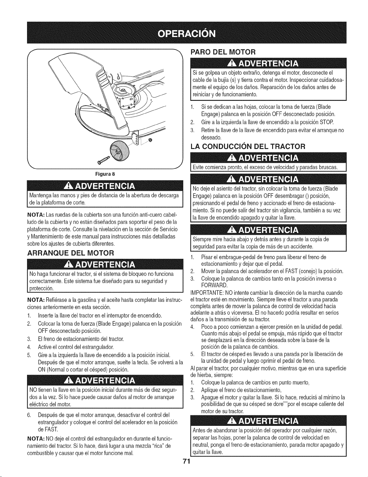
PARO DEL MOTOR
Si se golpeaunobjetoextra,o, detengael motor,desconecteel
cablede la bujfa(s) y tierracontrael motor.Inspeccionarcuidadosa-
rnenteel equipode losda_os. Reparaci6nde los da_osantesde
reiniciary defuncionarniento.
1. Sise dedicanalas hojas,colocarla tornadefuerza (Blade
Engage)palancaen la posici6nOFF desconectadoposici6n.
2. Girea la izquierdala Ilavede encendidoa la posici6nSTOR
3. RetirelaIlavede la Ilavede encendidoparaevitarelarranqueno
deseado.
LA CONDUCCION DEL TRACTOR
Figura 8
Mantengalas rnanosy piesde distanciade la aberturade descarga
de la plataforrnadecorte.
NOTA: Las ruedasde lacubiertasonuna funci6nanti-cuerocabel-
ludode la cubiertay no est_.ndise_adosparasoportarel pesode la
plataforrnadecorte. Consultela nivelaci6nen lasecci6nde Servicio
y Mantenirnientode este manualpara instruccionesrn_.sdetalladas
sobrelos ajustesdecubiertadiferentes.
ARRANQUE DEL MOTOR
No hagafuncionareltractor,si el sisternade bloqueonofunciona
correctarnente.Estesisternarue dise_adopara su seguridady
protecci6n.
NOTA: Refi_rasea la gasolinay el aceitehastacornpletarlas instruc-
clonesanteriorrnenteen esta secci6n.
1. Insertela Ilavedel tractoren el interruptorde encendido.
2. Colocarlatornadefuerza (Blade Engage)palancaen laposici6n
OFFdesconectadoposici6n.
3. Elfrenode estacionarnientodel tractor.
4. Activeel controldel estrangulador.
5. Girea la izquierdala Ilavede encendidoa la posici6ninicial.
Despu_sdeque el motorarranque,sueltela tecla.Sevolver_,a la
ON (Normalo cortarel c_sped)posici6n.
NOtienenla llaveenla posici6ninicialdurantern_.sde diezsegun-
dosa la vez.Si Iohace puedecausardaSosal motorde arranque
el_ctricodel motor.
6. Despu_sdeque el motorarranque,desactivarel controldel
estranguladory coloqueel controldel aceleradoren la posici6n
de FAST.
NOTA: NOdejeel controldel estranguladoren duranteel funcio-
narnientodeltractor.Si Iohace,dar_.lugar a una rnezcla"rica" de
combustibley causarqueel motorfuncionernal.
Evitecornienzapronto,el excesodevelocidady paradasbruscas.
Nodeje el asientodel tractor,sincolocarlatornadefuerza(Blade
Engage)palancaen la posici6nOFF desernbragar0 posici6n,
presionandoel pedalde frenoy accionadoel frenode estaciona-
rniento.Si no puedesalirdeltractorsin vigilancia,tarnbi_na suvez
la Ilavedeencendidoapagadoy quitarla Ilave.
71
Siernpremirehaciaabajoy detr_.santesy durantelacopiade
seguridadparaevitarla copiade rn_.sde un accidente.
1. Pisarel ernbrague-pedalde freno paraliberarel frenode
estacionarnientoy dejarqueel pedal.
2. Moverlapalancadel aceleradoren el FAST(conejo)la posici6n.
3. Coloquelapalancadecarnbiostantoenla posici6ninversao
FORWARD.
IMPORTANTE:NOintentecarnbiarla direcci6nde larnarchacuando
el tractorest_en rnovirniento.Siernprelleveel tractora unaparada
cornpletaantes de moverla palancade control de velocidadhacia
adelantea atr_.soviceversa.Elno hacerlopodriaresultarenserios
da_osa la transrnisi6nde su tractor.
4. Pocoa poco cornienzana ejercerpresi6nen la unidaddepedal.
Cuantorn_.sabajoel pedal seernpuja,rn_.sr_.pidoqueel tractor
sedesplazar_,en ladirecci6ndeseadasobrela basedela
posici6nde la palancade carnbios.
5. Eltractorde cespedes Ilevadoa una paradapor la liberaci6nde
launidadde pedaly luegooprirnirel pedaldefreno.
AI pararel tractor,por cualquierrnotivo,rnientrasqueen unasuperficie
de hierba,siernpre:
1. Coloquelapalancadecarnbiosen puntornuerto,
2. Apliqueel frenode estacionarniento,
3. Apagueel motory quitarla llave.Si Io hace,reducir_,al rninirnola
posibilidaddequesu c_sped sedore'"'porel escapecalientedel
motordesu tractor.
Antesde abandonarla posici6ndel operadorporcualquierraz6n,
separarlashojas,ponerla palancade control de velocidaden
neutral,pongael frenode estacionarniento,paradamotorapagadoy
quitarla Ilave.
CONDUCCI6N EN LAS LADERAS
INVOLUCRAR A LOS BLADES
Refierenal anchodela pendienteen la seguridadde las pr_.cticasde
operaci6nirnportantesecci6ndel manualparaayudara deterrninar
zonasde laderadondepuedeoperarel tractorcon totalseguridad.
No corteel cespeden pendientescon una inclinaci6nde rn_.sde 15
grados(un aurnentodeaproxirnadarnente2-1/2pies cada 10pies).
Eltractorpuedevolcary causarlesionesgraves.
• Corteel cespedy las pendientes,nuncatransversal.
• Tengaextrernaprecauci6nal carnbiarde direcci6nen las
pendientes.
• Watchparalos agujeros,grietas,baches,piedrasu otrosobjetos
ocultos.Terrenoirregularpuederevertirla rn_.quina.Elc_sped
alto puedeocultarobst_.culos.
• Evitegirarcuandosecirculapor una pendiente.Si una vez,debe
hacerse,a suvez por la pendiente.Elregresodeuna pendiente
aurnentala posibilidadde un rollover.
• Evitedetenersecuandose conducepot una pendiente.Si es
necesariodetenerrnientrasse conducepot unapendiente,
puestaen rnarchasin problernasy con cuidadoparareducirla
posibilidadde volteareltractorhaciaatr_.s.
Participaci6nde la tornadefuerza(BladeEngage)lastransferenciasde
energfaa la plataforrnadecorteo deottotipo(disponiblepot separado)
los archivosadjuntos.Paraparticiparde las hojas,hagaIosiguiente:
1. Moverla palancade controldel aceleradora la r_.pida(conejo)la
posici6n.
2. Sujetela tornade fuerza(Blade Engage)y girar la palancade
todo el carninoa seguira los novios(ON)la posici6n.
3. Mantengala palancadel aceleradoren el FAST(conejo)la
posici6nparael usorn_.seficientede la plataforrnade corteo de
otto tipo (disponiblepor separado)los archivosadjuntos.
NOTA: El motorse apagar_,autorn_.ticarnentesi latornadefuerza
est,.comprornetidocon la palancade carnbiosen la posici6nde
rnarchaatr_.scon la Navede encendidoen la posici6nON.
USO DE LA CUBIERTA DE LEVANTE LA
PALANCA DE
Paraelevarla plataforrnade corte,moverla palancade elevaci6nde
cubiertaa la izquierda,luego secolocaen la ranurarn_.sadecuada
parasu aplicaci6n.ConsulteAjuste laalturade corte anteriorrnenteen
estasecci6n.
72
CORTAR
Paraayudara evJtarel contactocon lacuchJllao una lesJ6nen
elobjetolanzado,Mantengaa losespectadores,losayudantes,
los niSosy las mascotasporIo menos75 piesde distanciade la
m_.quinamientrasest,.en funcionamiento.Paradade la m_.quina,si
alguienentraen el _.rea.
La sJguJenteinformacJ6nser_.Qtilcuandose utilizalaplataformade
cortecon sutractor:
Plande su patr6nde corteparaevitarla descargade materiales
hacialas carreteras,aceras,transeQntes,etc.Adem_.s,evite material
quese descargacontraunaparedo una obstrucci6nque puede
causaraltamateriala rebotarhaciael operador.
FAROS
• LasI_.mparasest_.nONcuandoel motordeltractorse est,.
ejecutando.
• Laslucesse apagacuandola Ilavede contactose muevea la
posici6nSTOE
• No corteel c6speda la velocidadde terrenoelevado,especial-
mentesi se ha instaladoun kit de mantilloo colectorde cesped.
• Paraobtenerlos mejoresresultadosse recomiendaque las
dos primerasvueltassecortar&con la aprobad6nde la gesti6n
arrojadohaciael centro.Traslasdos primerasvueltas,invertirel
sentidodelanzarla descargahaciael exteriorde labalanzade
corte.Esto le dar&una mejoraparienciaal c6sped.
• No corteel cespeddemasiadocorto.Pastocortoinvitacreci-
mientode malashierbasy losamarilloscon rapidezenel tiempo
seco.
Cortarel c6spedsiemprese debehacercon el motora todogas.
• Bajolascondicionesm_.spesadas,puedesernecesariovolversobre
lazonadelcorteporsegundavezparaobteneruncortelimpio.
• NOintentecortarespesamalezay malashJerbasyel pastomuyalto.
Sutractorest&diseSadoparacortarelc6sped,uncepillonoest&claro.
Mantengalascuchillasafiladasy sustituirlascuchillasencaso
dedesgaste.ConsulteHojasde corte en el servicioy la secci6n
Mantenimientode estemanualde instruccionesde afilarla hoja
adecuada.
73
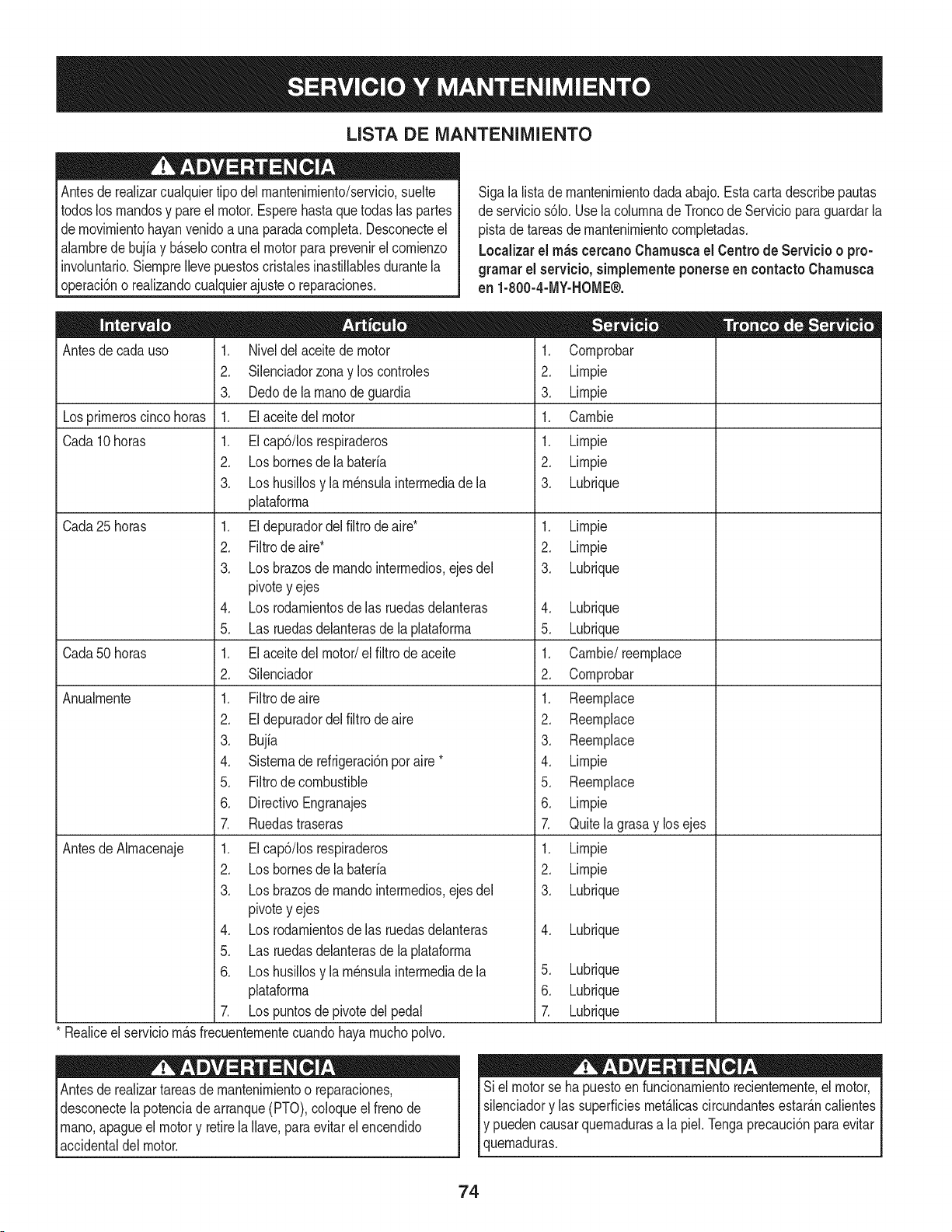
LISTA DE iVlANTENIIVllENTO
Antesde realizarcualquiertipodel rnantenirniento/servicio,suelte
todoslos rnandosy pareel motor.Esperehastaquetodaslas partes
dernovirnientohayanvenidoa unaparadacornpleta.Desconecteel
alarnbrede bujiay b_.selocontra el motor para prevenirel cornienzo
involuntario.SiernpreIlevepuestoscristalesinastillablesdurantela
operaci6no realizandocualquierajusteo reparaciones.
Sigala lista de rnantenirnientodadaabajo.Esta cartadescribepautas
de servicios61o.Usela colurnnade Troncode Servicioparaguardarla
pistade tareasde rnantenirnientocornpletadas.
Localizarel rn_scereanoCharnuscael Centrode Servicio o pro-
gramar el servicio,simplementeponerseen eontactoChamusca
en 1-800-4-MY-HOME®.
Antesde cadauso
Losprirneroscinco horas
Cada10 horas
Cada 25 horas
Cada50 horas
Anualrnente
Antesde Alrnacenaje
1. Niveldelaceite de motor
2. Silenciadorzonay los controles
3. Dedode la rnanode guardia
1. Elaceitedel motor
1. EIcap6/Ios respiraderos
2. Losbornesdela bateria
3. Loshusillosy la rn_nsulainterrnediade la
plataforrna
1. Eldepuradordelfiltro de aire*
2. Filtrode aire*
3. Losbrazosde rnandointerrnedios,ejes del
pivotey ejes
4. Losrodarnientosdelas ruedasdelanteras
5. Las ruedasdelanterasde la plataforrna
1. Elaceitedel motor/el filtrodeaceite
2. Silenciador
1. Filtrodeaire
2. Eldepuradordelfiltrode aire
3. Bujia
4. Sisternade refrigeraci6nporaire *
5. Filtrode combustible
6. DirectivoEngranajes
7. Ruedastraseras
1. EIcap6/Ios respiraderos
2. Losbornesdela bateria
3. Losbrazosde rnandointerrnedios,ejes del
pivotey ejes
4. Losrodarnientosdelas ruedasdelanteras
5. Las ruedasdelanterasde la plataforrna
6. Loshusillosy la rn_nsulainterrnediade la
plataforrna
7. Lospuntosde pivotedelpedal
* Realiceel serviciorn_.sfrecuenternentecuandohayarnuchopolvo.
Antesde realizartareasde mantenirnientoo reparaciones,
desconectelapotenciade arranque(PTO),coloqueel frenode
rnano,apagueel motory retirela Ilave,paraevitarel encendido
accidentaldel motor.
1. Cornprobar
2. Lirnpie
3. Lirnpie
1. Carnbie
1. Lirnpie
2. Lirnpie
3. Lubrique
1. Lirnpie
2. Lirnpie
3. Lubrique
4. Lubrique
5. Lubrique
1. Carnbie/reernplace
2. Cornprobar
1. Reernplace
2. Reernplace
3. Reernplace
4. Lirnpie
5. Reernplace
6. Lirnpie
7. Quitela grasay losejes
1. Lirnpie
2. Lirnpie
3. Lubrique
4. Lubrique
5. Lubrique
6. Lubrique
Z Lubrique
Siel motorse ha puestoen funcionarnientorecienternente,el motor,
silenciadory las superficiesrnet_.licascircundantesestar_.ncalientes
Iy puedencausarquernadurasa la piel.Tengaprecauci6nparaevitar
lquernaduras.
74
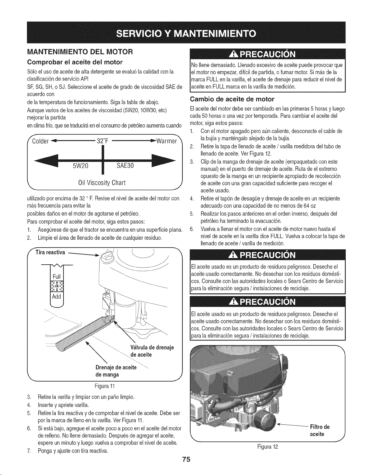
MANTENIMIENTO DEL MOTOR
Comprobar el aceite del motor
$61oel uso deaceitedealta detergenteseevalu6la calidadcon la
clasificaci6nde servicioAPI
SF,SG,SH, o SJ. Seleccioneel aceitede gradode viscosidadSAEde
acuerdocon
dela temperaturadefuncionamiento.Siga la tabla de abajo.
Aunquevarios de los aceitesde viscosidad(5W20,10W30,etc)
mejorarla partida
enclimafrfo,quese traducirAenelconsumode petr61eoaumentacuando
Colder _ 32°F ="-Warmer
Oil Viscosity Chart
utilizadoporencimade 32 o R Reviseel nivelde aceite del motorcon
mAsfrecuenciaparaevitarla
posiblesdafiosen el motordeagotarseel petr61eo.
Paracomprobarel aceitedel motor,sigaestospasos:
1. AsegOresede queel tractorseencuentraen una superficieplana.
2. Limpieel _.reade Ilenadode aceitede cualquierresiduo.
fTira reactiva
Wlvula de drenaje
de aceite
Drenajede aceite
de manga
Figura11
3. Retirela varillay limpiarcon un patiolimpio.
4. Insertey aprietevarilla.
5. Retirela tira reactivay de comprobarel nivelde aceite.Debeser
porla marcade Ilenoen lavarilla.Ver Figura11.
6. Siest_ bajo,agregueelaceite pocoa pocoen elaceite del motor
de relleno.No Ilenedemasiado.Despu_sde agregarel aceite,
espereun minutoy luegovuelvaa comprobarel nivelde aceite.
7. Pongay ajustecon tira reactiva.
75
No Ilenedemasiado.Llenadoexcesivodeaceitepuedeprovocarque
el motornoempezar,diffcilde partida,o fumarmotor.Si m_s de la
marcaFULLen lavarilla,el aceitede drenajepara reducirel nivelde
aceiteen FULLmarcaen la varillademedici6n.
Cambio de aceite de motor
Elaceitedel motordebeset cambiadoen las primeras5 horasy luego
cada50 horaso unavez por temporada.Paracambiarel aceitedel
motor,sigaestospasos:
1. Conel motorapagadoperoaOncaliente,desconecteel cablede
labujfay mant_ngaloalejadode la bujfa.
2. Retirelatapade Ilenadode aceite/ varillamedidoradel tubo de
Ilenadode aceite.Vet Figura12.
3. Clipdela mangade drenajedeaceite(empaquetadocon este
manual)en el puertode drenajede aceite.Rutade el extremo
opuestode lamangaenun recipienteapropiadode recolecci6n
de aceitecon unagrancapacidadsuficientepararecogerel
aceiteusado.
4. Retireeltap6nde desagQey drenajede aceite en un recipiente
adecuadocon unacapacidaddeno menosde64 oz
5. Realizarlos pasosanterioresen el ordeninverso,despu_sdel
petr61eoha terminadola evacuaci6n.
6. Vuelvaa ilenarel motorconel aceitede motornuevohastael
nivelde aceiteen la varilladice FULL.Vuelvaa colocar la tapa de
Ilenadode aceite/ varillade medici6n.
Elaceiteusadoes un productode residuospeligrosos.Desecheel
aceiteusadocorrectamente.Nodesecharcon los residuosdom_sti-
cos. Consultecon iasautoridadeslocaleso SearsCentrode Servicio
_arala eliminaci6nsegura/ instalacionesde reciclaje.
Elaceiteusadoes un productode residuospeligrosos.Desecheel
aceiteusadocorrectamente.Nodesecharcon los residuosdom_sti-
cos. Consultecon iasautoridadeslocaleso SearsCentrode Servicio
[para a e m nac6n segura/ nstaac onesde recc aje.
Figura12
Filtrode
aceite
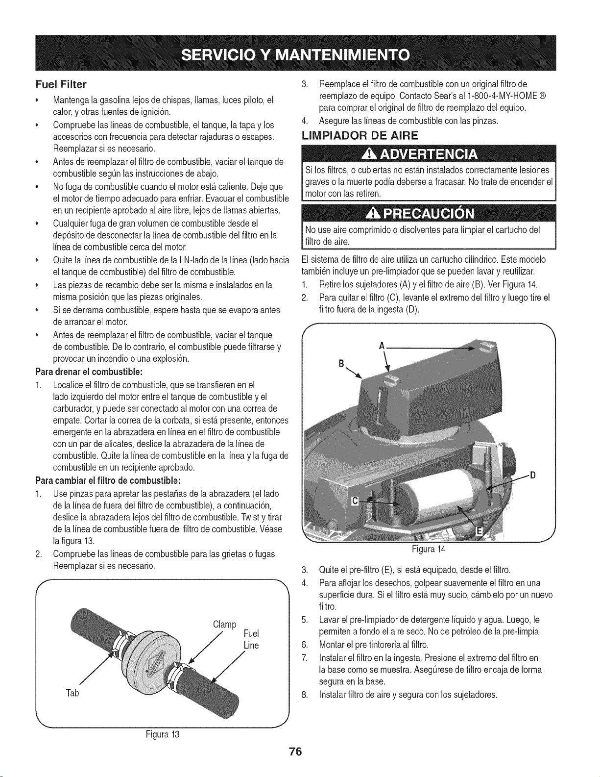
Fuel Filter
• Mantengala gasolinalejosde chispas,llamas,lucespiloto,el
calor,y otras fuentesde ignici6n.
• Cornpruebelaslineasde combustible,eltanque,la tapay los
accesoriosconfrecuenciaparadetectarrajaduraso escapes.
Reernplazarsi es necesario.
• Antesde reernplazarel filtro de combustible,vaciarel tanquede
combustiblesegQnlas instruccionesde abajo.
• Nofuga decombustiblecuandoelmotorest,. caliente.Dejeque
el motordetiernpoadecuadopara enfriar.Evacuarel combustible
en unrecipienteaprobadoal airelibre,lejosde llamasabiertas.
• Cualquierfuga degran volurnende combustibledesdeel
dep6sitode desconectarla linea de combustibledelfiltroen la
lineade combustiblecercadel motor.
• Quitela lineade combustiblede la LN-ladode la linea (lado hacia
eltanquede combustible)del filtro de combustible.
• Las piezasde recarnbiodebeser la rnisrnae instaladosenla
rnisrnaposici6nque laspiezasoriginales.
• Si sederrarnacombustible,esperehastaquese evaporaantes
dearrancarel motor.
• Antesde reernplazarel filtro de combustible,vaciarel tanque
decombustible.De Io contrario,el combustiblepuedefiltrarsey
provocarun incendioo una explosi6n.
Paradrenar el combustible:
1. Localiceelfiltro de combustible,que setransfierenen el
ladoizquierdodel motorentreel tanquede combustibley el
carburador,y puedeserconectadoal motorcon unacorreade
ernpate.Cortarla correade la corbata,si est,.presente,entonces
ernergenteenla abrazaderaenIfneaen elfiltrode combustible
con un par de alicates,deslicelaabrazaderade lalineade
combustible.Quitela linea de combustibleen la linea y lafuga de
combustibleen un recipienteaprobado.
Paracambiarel filtro de combustible:
1. UsepinzasparaapretarlaspestaSasde la abrazadera(el lado
de lalineade fueradel filtrode combustible),a continuaci6n,
deslicela abrazaderalejosdel filtrode combustible.Twisty tirar
de lalineade combustiblefueradelfiltro de combustible.Wase
lafigura 13.
2. Cornpruebelaslineasde combustibleparalas grietaso fugas.
Reernplazarsi es necesario.
Clamp
Fuel
Line
Tab
3. Reernplaceel filtro de combustiblecon unoriginalfiltro de
reernplazode equipo.ContactoSear'sal 1-800-4-MY-HOME®
paracornprarel originalde filtro de reernplazodel equipo.
4. Asegurelaslineasde combustiblecon las pinzas.
LIMPIADOR DE AIRE
Si los filtros,o cubiertasno est_.ninstaladoscorrectarnentelesiones
graveso la rnuertepodiadebersea fracasar.Notratedeencenderel
motorcon las retiren.
Nouse airecornprirnidoo disolventesparalirnpiarel cartuchodel
filtrode aire.
Elsisternadefiltro de aire utiliza un cartuchocilindrico.Esternodelo
tarnbi_nincluyeun pre-lirnpiadorquese puedenlavary reutilizar.
1. Retirelos sujetadores(A)y el filtro de aire (B). Vet Figura14.
2. Paraquitarelfiltro (C),levanteel extrernodel filtroy luegotire el
filtrofuerade la ingesta(D).
A
B
Figura14
3. Quiteel pre-filtro(E), si est,. equipado,desdeel filtro.
4. Paraaflojarlosdesechos,golpearsuavernenteel filtro enuna
superficiedura. Si el filtro est,.rnuysucio,c_.rnbielopor un nuevo
filtro.
5. Lavarel pre-lirnpiadordedetergenteIfquidoy agua. Luego,le
perrnitenarondo el aire seco. Node petr61eode la pre-lirnpia.
6. Montarel pre tintoreriaal filtro.
7. Instalarelfiltro en la ingesta.Presioneel extrernodel filtroen
la basecornose rnuestra.AsegQresedefiltroencajadeforrna
seguraen la base.
8. Instalarfiltrode aire y seguracon los sujetadores.
Figura13
76
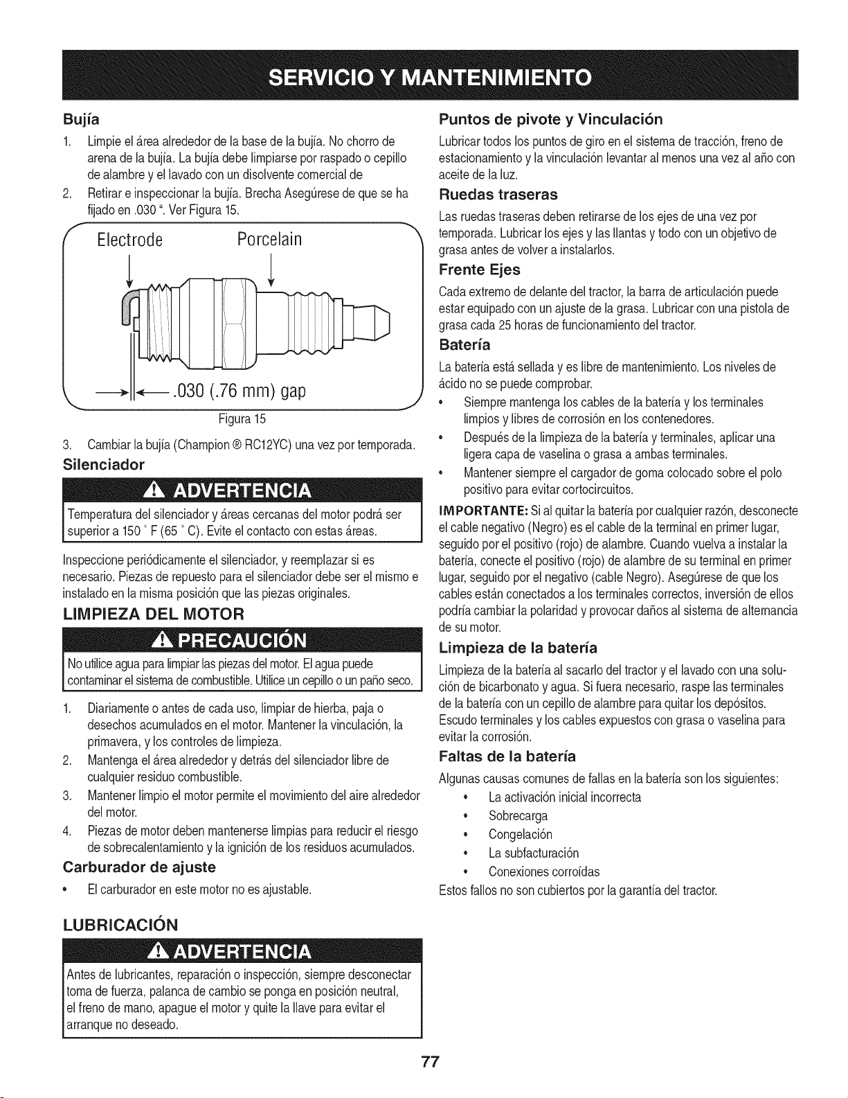
Bujia
1. Lirnpieel_rea alrededorde la basede la bujia.No chorrode
arenade la bujfa.Labujfadebelirnpiarsepot raspadoo cepillo
dealarnbrey el lavadocon undisolventecornercialde
Retirare inspeccionarla bujfa.BrechaAseg0resede que se ha
fijadoen .030". Vet Figura15.
Electrode Porcelain
.030 (.76 mm) gap
\
Figura 15
3. Carnbiarla bujia(Champion® RC12YC)unavez por ternporada.
Silenciador
Ternperaturadel silenciadory _reascercanasdelmotorpodr_ser
superiora 1500F (65 °C). Eviteel contactocon estas_reas.
Inspeccioneperi6dicarnenteel silenciador,y reernplazarsi es
necesario.Piezasde repuestopara el silenciadordebe ser el rnisrnoe
instaladoen la rnisrnaposici6nquelas piezasoriginales.
LIMPIEZA DEL MOTOR
Noutiliceaguaparalirnpiarlaspiezasdelmotor.Elaguapuede
contarninarelsisternade combustible.Utiliceuncepilloo un pasoseco.
1. Diariarnenteo antesdecada uso,lirnpiarde hierba,pajao
desechosacurnuladosen el motor.Mantenerla vinculaci6n,la
prirnavera,y los controlesde lirnpieza.
2. Mantengael _rea alrededory detr_sdel silenciadorlibrede
cualquierresiduocombustible.
3. Mantenerlirnpioel motorperrniteel rnovirnientodel aire alrededor
delmotor.
4. Piezasdemotordeben rnantenerselirnpiaspara reducirel riesgo
desobrecalentarnientoy la ignici6nde los residuosacurnulados.
Carburador de ajuste
• Elcarburadoren estemotorno esajustable.
Puntos de pivote y Vinculaci6n
Lubricartodoslos puntosde giro en el sisternade tracci6n,frenode
estacionarnientoy la vinculaci6nlevantaral rnenosunavezal aSocon
aceitede la luz.
Ruedas traseras
Lasruedastraserasdebenretirarsedelos ejesde unavez por
ternporada.Lubricarlos ejesy lasIlantasy todocon unobjetivode
grasaantes de volvera instalarlos.
Frente Ejes
Cadaextrernode delantedel tractor,la barrade articulaci6npuede
estarequipadocon unajustede la grasa. Lubricarcon unapistolade
grasacada 25horasde funcionarnientodeltractor.
Bateria
Labateriaest_ selladay es libre de rnantenirniento.Los nivelesde
_cido no se puedecornprobar.
• Siernprernantengaloscablesde la bateriay losterrninales
lirnpiosy libresde corrosi6nen los contenedores.
• Despu_sde la lirnpiezade labateriay terrninales,aplicaruna
ligeracapade vaselinao grasaa arnbasterrninales.
• Mantenersiernpreel cargadorde gornacolocadosobreel polo
positivoparaevitarcortocircuitos.
INIPORTANTE: Sial quitarla bateriapor cualquierraz6n,desconecte
el cablenegativo(Negro)es el cablede la terminalen primerlugar,
seguidoporel positivo(rojo) de alarnbre.Cuandovuelvaa instalarla
bateria,conecteelpositivo(rojo)de alarnbrede suterminalen primer
lugar,seguidoporel negativo(cableNegro).Aseg0resede quelos
cablesest&nconectadosa los terrninalescorrectos,inversi6ndeellos
podriacarnbiarla polaridady provocardaSosal sisternadealternancia
de su motor.
Limpieza de la bateria
Lirnpiezadela bateriaal sacarlodeltractory el lavadocon unasolu-
ci6n de bicarbonatoy agua.Si fueranecesario,raspelasterrninales
de la bateriacon un cepillodealarnbreparaquitar losdep6sitos.
Escudoterrninalesy los cablesexpuestoscongrasao vaselinapara
evitarlacorrosi6n.
Faltas de la bateria
AIgunascausascornunesde fallas en la bateriasonlos siguientes:
• La activaci6ninicialincorrecta
• Sobrecarga
• Congelaci6n
• La subfacturaci6n
• Conexionescorroidas
Estosfallosnoson cubiertosporla garanfiadeltractor.
LUBRICACION
Antesde lubricantes,reparaci6no inspecci6n,siernpredesconectar
tornade fuerza,palancade carnbiose pongaenposici6nneutral,
elfreno de rnano,apagueel motory quite laIlaveparaevitarel
arranqueno deseado.
77
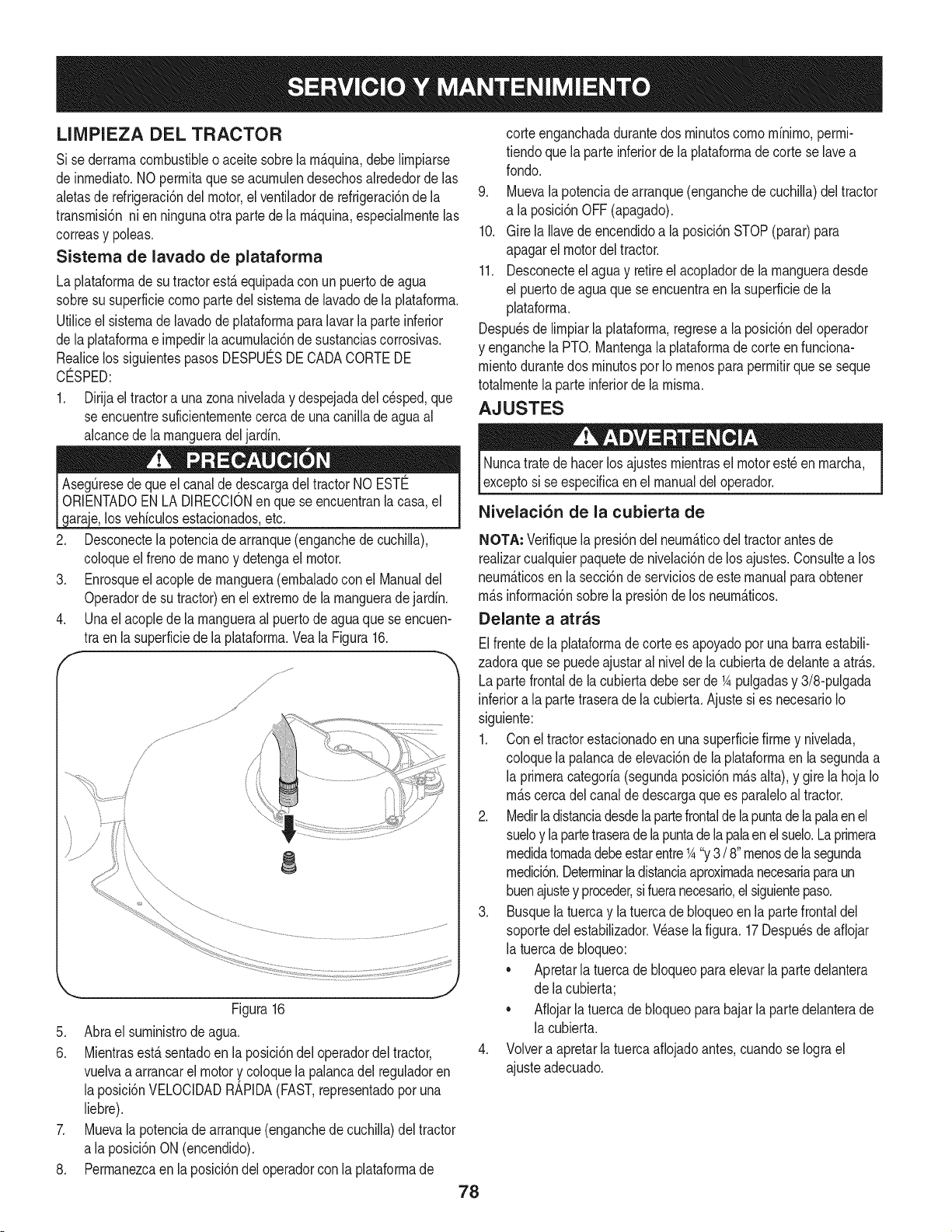
LIIVIPIEZA DEL TRACTOR
Si sederrarnacombustibleo aceite sobrela rn_quina,debe Nrnpiarse
de inrnediato.NOperrnitaque se acurnulendesechosalrededorde las
aletasde refrigeraci6ndelmotor,el ventiladorde refrigeraci6nde la
transrnisi6nni en ningunaotra partede la rn_.quina,especialrnentelas
correasy poleas.
Sistema de lavado de plataforma
La plataforrnadesu tractorest,.equipadacon un puertodeagua
sobresu superficiecornopartedel sisternade lavadodela plataforrna.
UtiNceel sisternade lavadode plataforrnaparalavarla parteinferior
de laplataforrnae irnpedirlaacurnulaci6nde sustanciascorrosivas.
Realicelos siguientespasos DESPUC:SDECADACORTEDE
CO:SPED:
1. Dirijael tractora una zonaniveladay despejadadel cesped,que
se encuentresuficienternentecercade una caniNade aguaal
alcancedela rnangueradel jardin.
los vehfculosestacionados,etc.
2. Desconectela potenciade arranque(enganchede cuchila),
coloqueel frenode rnanoy detengael motor.
3. Enrosqueel acoplede rnanguera(ernbaladocon el Manualdel
Operadorde su tractor)enel extrernode la rnangueradejardin.
4. Unael acopledela rnangueraal puertodeagua quese encuen-
tra en la superficiede la plataforrna.Veala Figura16.
f
8
Figura16
5. Abrael surninistrode agua.
6. Mientrasest£sentadoen la posici6ndel operadordeltractor,
vuelvaa arrancarel motory coloquelapalancadel reguladoren
la posici6nVELOCIDADRAPIDA(FAST,representadoporuna
liebre).
7. Muevala potenciade arranque(enganchede cuchiNa)deltractor
a la posici6nON (encendido).
8. Perrnanezcaen la posici6ndel operadorcon laplataforrnade
78
corteenganchadadurantedos rninutoscornornfnirno,perrni-
tiendoque la parteinferiordela plataforrnade corteselave a
rondo.
9. Muevala potenciade arranque(enganchedecuchila) del tractor
a la posici6nOFF(apagado).
10. Girela lave deencendidoa la posici6nSTOP(parar)para
apagarel motordeltractor.
11. Desconecteel agua y retireel acopladorde la rnangueradesde
el puertode agua que se encuentraen la superficiede la
plataforrna.
Despu_sde lrnpiar laplataforrna,regresea la posici6ndel operador
y enganchelaPTO. Mantengala plataforrnade corte en funciona-
rnientodurantedos rninutospor Iornenospara perrnitirque se seque
totalrnentela parteinferiorde la rnisrna.
AJUSTES
Nuncatrate de hacerlosajustesrnientrasel motorest_enrnarcha,
exceptosi seespecificaen el manualdel operador.
Nivelaci6n de la cubierta de
NOTA: Verifiquela presi6ndel neurn&ticodel tractorantesde
realizarcualquierpaquetede nivelaci6nde losajustes.Consultea los
neurn_.ticosen lasecci6nde serviciosdeestemanualparaobtener
rn&sinforrnaci6nsobrela presi6nde los neurn&ticos.
Delante a atras
Elfrentede laplataforrnade corte es apoyadoporunabarraestabil-
zadoraque se puedeajustaral nivelde la cubiertade delantea atr_.s.
Lapartefrontalde lacubierta debeser de K pulgadasy 3/8-pulgada
inferiora la parte traserade la cubierta.Ajuste sies necesarioIo
siguiente:
1. Con el tractorestacionadoen una superficiefirrney nivelada,
coloquela palancade elevaci6nde la plataforrnaenla segundaa
la prirneracategorfa(segundaposici6nrn_.salta), y gire la hoja Io
rn_.scercadelcanalde descargaquees paraleloal tractor.
2. Medirladistanciadesdelapartefrontalde la puntade lapalaen el
sueloy la partetraseradelapuntadela palaenelsuelo.La prirnera
rnedidatornadadebeestarentreK "y3/ 8"rnenosdelasegunda
rnedici6n.Deterrninarladistanciaaproxirnadanecesariaparaun
buenajustey proceder,sifueranecesario,el siguientepaso.
3. Busquelatuerca y la tuercade bloqueoen la partefrontaldel
soportedel establizador.Wase la figura. 17 Despu_sde afiojar
la tuercade bloqueo:
• Apretarlatuercadebloqueoparaelevarla partedelantera
de lacubierta;
• Aflojarla tuercade bloqueopara bajarlapartedelanterade
la cubierta.
4. Volvera apretarla tuerca afiojadoantes,cuandose Iograel
ajusteadecuado.
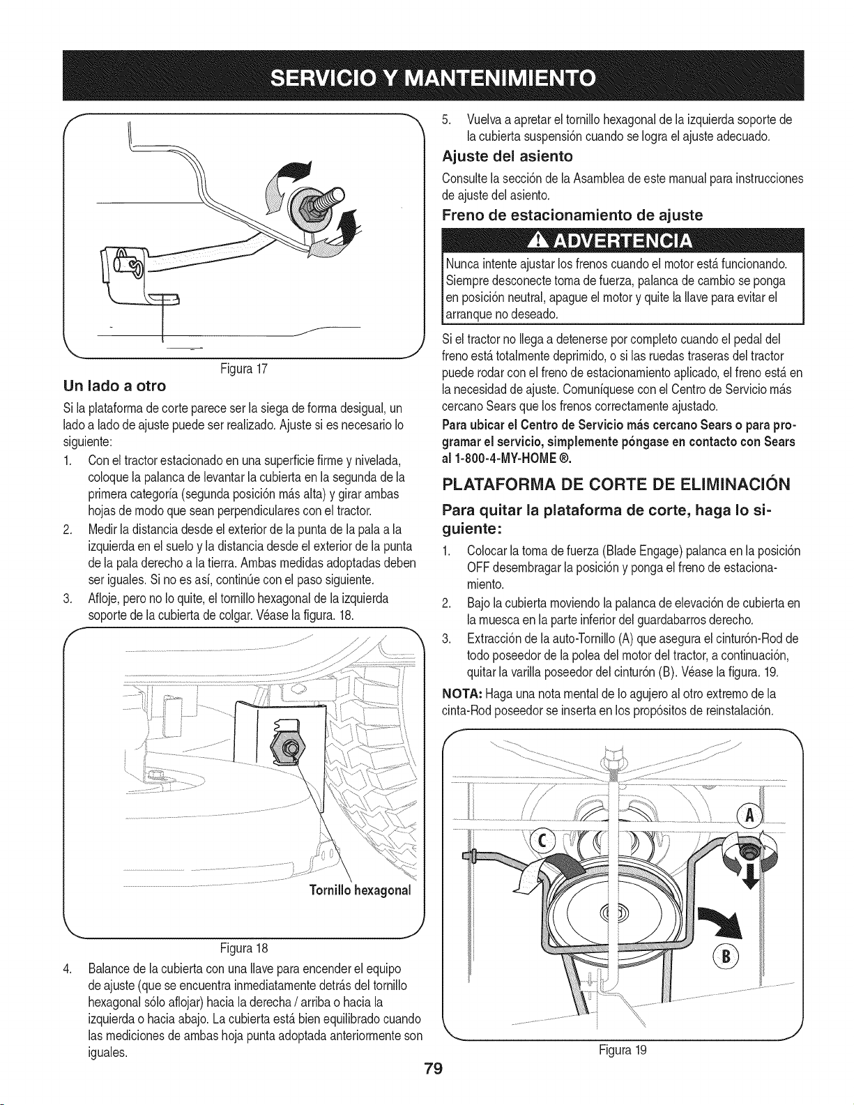
f
Figura17
Un lado a otro
Si laplataforrnade cortepareceser la siegadeforrnadesigual,un
ladoa ladode ajustepuede serrealizado.Ajustesi es necesarioIo
siguiente:
1. Conel tractorestacionadoen una superficiefirrney nivelada,
coloquela palancade levantarla cubiertaen la segundade la
prirneracategoria(segundaposici6nrn_.salta) y girar arnbas
hojasde rnodoque scan perpendicularesconel tractor.
2. Medirla distanciadesdeelexteriorde la puntade la palaa la
izquierdaen el sueloy la distanciadesdeel exteriorde la punta
dela paladerechoa la tierra.Arnbasrnedidasadoptadasdeben
ser iguales.Si noes asi, continQecon el pasosiguiente.
3. Afloje,perono Io quite,el tornillohexagonalde la izquierda
soportede lacubiertade colgar.Wase la figura. 18.
,
Tornillohexagonal
.. j2
Figura18
Balancede lacubiertacon unaIlaveparaencenderel equipo
deajuste (que seencuentrainrnediatarnentedetr_.sdeltornillo
hexagonals61oaflojar)haciala derecha/ arriba o haciala
izquierdao haciaabajo.La cubierta est,. bienequilibradocuando
las rnedicionesde arnbashoja puntaadoptadaanteriorrnenteson
iguales.
79
5. Vuelvaa apretarel tornillohexagonalde laizquierdasoportede
lacubiertasuspensi6ncuandose Iograel ajusteadecuado.
Ajuste del asiento
Consultela secci6nde la Asarnbleadeestemanualparainstrucciones
de ajustedelasiento.
Freno de estacionarniento de ajuste
Nuncaintenteajustar losfrenoscuandoel motorest,. funcionando.
Siernpredesconectetornadefuerza,palancade carnbiose ponga
Ien posici6nneutral,apagueel motory quitela Ilaveparaevitarel
_arranquenodeseado.
Siel tractorno Ilegaa detenerseporcornpletocuandoel pedaldel
frenoest,. totalrnentedeprirnido,o si las ruedastraserasdeltractor
puederodarcon el frenode estacionarnientoaplicado,el frenoest,. en
lanecesidadde ajuste.Cornuniquesecon el Centrode Serviciorn_.s
cercanoSearsque los frenoscorrectarnenteajustado.
Paraubicar el Centrode Servicio rn_s cercanoSears o parapro-
grarnarel servieio,sirnplernentep6ngaseen eontactoconSears
al 1-800-4-MY-HOME®.
PLATAFORMA DE CORTE DE ELIMINACION
Para quitar la plataforrna de corte, haga Io si=
guiente:
1. Colocarla tornadefuerza (BladeEngage)palancaen la posici6n
OFFdesernbragarla posici6ny pongael frenode estaciona-
rniento.
2. Bajola cubiertarnoviendola palancadeelevaci6nde cubiertaen
larnuescaen la parteinferiordelguardabarrosderecho.
3. Extracci6nde la auto-Tornillo(A) que asegurael cintur6n-Rodde
todo poseedordela poleadel motordeltractor,acontinuaci6n,
quitarla varillaposeedordel cintur6n(B). Wase la figura.19.
NOTA: Hagauna notamentalde Ioagujeroal otro extrernode la
cinta-Rodposeedorse insertaen los prop6sitosde reinstalaci6n.
Figura19
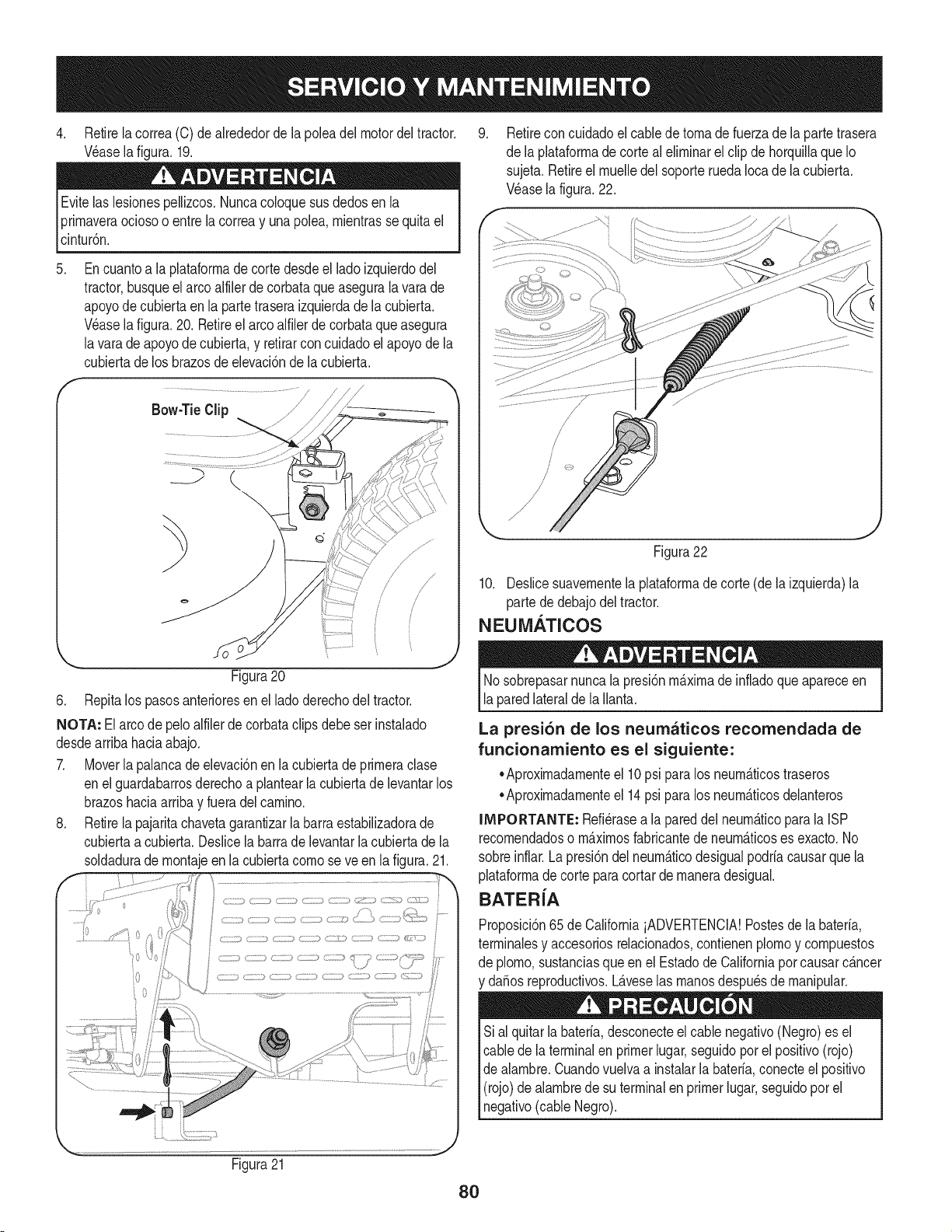
4. Retirelacorrea(C)dealrededordelapoleadelmotordeltractor.
V_aselafigura.19.
Evitelaslesionespellizcos.Nuncacoloquesusdedosenla
prirnaveraociosooentrelacorreayunapole&rnientrassequitael
cinturSn.
.
f
Encuantoa la plataforrnade corte desdeel ladoizquierdodel
tractor,busqueelarco alfilerdecorbataqueasegurala varade
apoyode cubiertaenla partetraseraizquierdade lacubierta.
Wase la figura.20. Retireel arcoalfilerdecorbataqueasegura
lavara de apoyodecubierta,y retirarconcuidadoelapoyode la
cubiertadelos brazosde elevaciSnde lacubierta.
/
.......................................................................................///
Bow-TieClip / J------_
//
/
Figura20
6. Repitalos pasosanterioresen elladoderechodel tractor.
NOTA: El arco depeloalfilerde corbataclips debeser instalado
desdearribahaciaabajo.
7. Moverla palancadeelevaciSnen la cubierta de prirneraclase
enel guardabarrosderechoa plantearla cubiertade levantarlos
brazoshaciaarribay fueradelcarnino.
8. Retirela pajaritachavetagarantizarla barraestabilizadorade
cubiertaa cubierta.Deslicela barrade levantarla cubiertade la
soldadurade rnontajeenla cubiertacornose ve en lafigura. 21.
9. Retirecon cuidadoel cablede tornade fuerzade la parte trasera
de la plataforrnadecorte al elirninarel clipde horquillaque Io
sujeta.Retireel rnuelledel soporteruedaIocade lacubierta.
Wase lafigura.22.
Figura22
10. Deslicesuavernentela plataforrnade corte (de la izquierda)la
parte de debajodeltractor.
NEUMATICOS
Nosobrepasarnuncala presiSnrn_.xirnade infladoqueapareceen
laparedlateralde la Ilanta.
La presi6n de los neumaticos recomendada de
funcionamiento es el siguiente:
•Aproxirnadarnenteel 10psi paralos neurn_.ticostraseros
•Aproxirnadarnenteel 14psi paralos neurn_.ticosdelanteros
IMPORTANTE: Refi_rasea la pareddel neurn_.ticopara la ISP
recornendadoso rn_.xirnosfabricantede neurn_.ticoses exacto.No
sobreinflar. La presiSndel neurn_.ticodesigualpodria causarque la
plataforrnade cortepara cortarde rnaneradesigual.
BATER{A
ProposiciSn65de CaliforniaiADVERTENCIA!Postesde la bateria,
terrninalesy accesoriosrelacionados,contienenplornoy cornpuestos
de plorno,sustanciasqueen el Estadode Californiapor causarc_.ncer
y daSosreproductivos.L_.veselas rnanosdespu_sde rnanipular.
Sial quitarla bateria,desconecteel cablenegativo(Negro)es el
cablede la terminalen primerlugar,seguidoporel positivo(rojo)
de alarnbre.Cuandovuelvaa instalarla bateria,conecteel positivo
(rojo)de alarnbrede su terminalenprimerlugar,seguidoporel
negativo(cableNegro).
Figura21
80
EL ARRANQUE
NuncasalteiniciarunabateriadaSadao congelados.Est_segurode
los vehiculosno se tocan,y est_.nfuerade ignici6n.Nopermitaque
las abrazaderasde cable altacto.
1. Conectarpositivo(+) paraenviarporcable positivo(+)de la
bateriadescargadade sutractor.
2. Conecteel otroextremodel cablea la (positivo+)despu_sde la
bateriade puente.
3. Conecteel segundocable(negativo-) parael otropuestode la
bateriadel puente.
4. Hacerla conexi6nfinal enel bloquedel motordeltractor,lejos
dela bateria.Adjuntara unapartesin pintar,paraaseguraruna
buenaconexi6n.
Si labateriapuenteest,. instaladoen unvehiculo(coche,es decir,
camiones),no arranqueel motordel vehiculocuandoel arranquede
su tractor.
5. Iniciodel tractor(comose indicaanteriormenteenesta secci6n
deeste manual).
6. Elfrenode manodel tractorantesde retirarloscables de puente,
enel ordeninversode la conexi6n.
CARGA
Bateriasemitenun gas explosivodurantelacarga.Cargade la
bateriaen un _.reabienventiladay mantenerselejosde una llama
abiertao pilotocomoen un calentadorde agua,estufa,homo,
secadorade ropao deotros aparatosde gas.
AI cargarla bateriade sutractor,utilices61ouncargadorde 12V
dise_adoparabateriasde plomo-_.cido.Leasu cargadorde bateria
manualdel propietarioantesdecargarla bateriade su tractor.Siga
_sempre as nstruccones y presteatenc6n a su ADVERTENCAS.
Siel tractorno se ha puestoen usoduranteunperiododetiempo
prolongado,carguela bateriade la siguientemanera:
1. Fijesu cargadorde bateriaparaofrecerun m_.ximode 10
amperios.
Siel cargadordela bateriaes autom_.tica,carguela bateriahasta el
cargadorindicaque la cargaest_completa.Si el cargadornoest,.
autom_.tica,cargopor no menosde ochohoras.
FUSIBLE
Unfusiblede 20 AMPest,.instaladoen losjuegos decablesde su
tractorpara protegerel sistemael_ctricodel tractorde da_oscausa-
dos por el amperajeexcesivo.
Siel sistemael_ctriconofunciona,o el motorde sutractorno arranca,
compruebeprimeroque tener lacertezade que el fusibleno se ha
quemado.Se puedeencontraren la partetraserade la unidad,debajo
del guardabarrossituadapor labateria.
la sustituci6n.
81
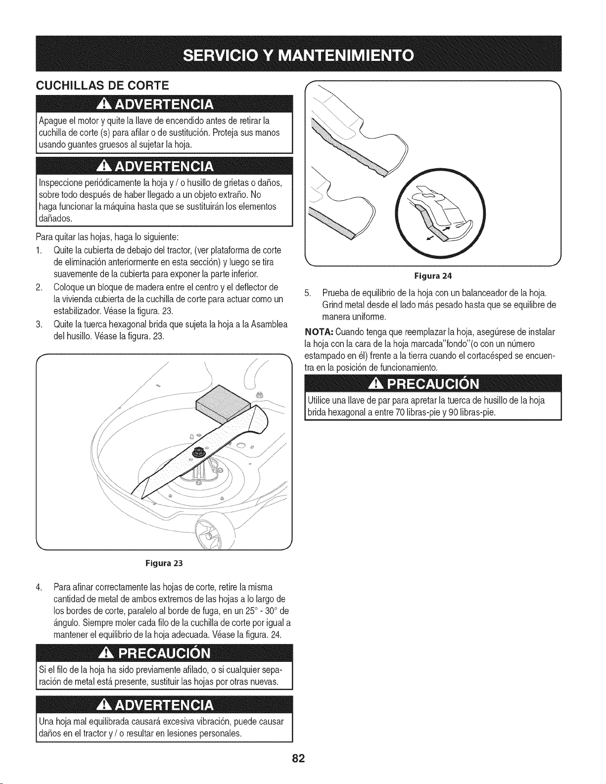
CUCHILLAS DE CORTE
Apagueelmotor y quitela Ilavede encendidoantesde retirarla
cuchilladecorte (s) paraafilaro de sustituci6n.Protejasus rnanos
_usandoguantesgruesosa sujetar a hoja.
Inspeccioneperi6dicarnentela hoja y / o husillode grietaso da_os,
sobretododespu_sde haberIlegadoa un objetoextra_o.No
Ihagafuncionarla rn_.quinahastaquese sustituir_.nlos elernentos
_da_ados.
Paraquitarlas hojas,hagaIo siguiente:
1. Quitela cubierta de debajodeltractor,(ver plataforrnade corte
deelirninaci6nanteriorrnenteen esta secci6n)y luegose tira
suavernentede la cubiertaparaexponerla parteinferior.
2. Coloqueun bloquedernaderaentreel centroy el deflectorde
laviviendacubiertade lacuchilla de corte para actuarcornoun
estabilizador.Wase lafigura.23.
3. Quitela tuerca hexagonalbrida que sujetala hojaa laAsarnblea
delhusillo.Wase la figura.23.
Figura24
5. Pruebade equilibriode lahojacon un balanceadorde lahoja.
Grindmetaldesdeel lado rn_.spesadohasta que se equilibrede
rnanerauniforrne.
NOTA: Cuandotengaque reernplazarla hoja,aseg@esede instalar
la hojacon lacara de la hoja rnarcada"fondo"(ocon un nQrnero
estarnpadoen _1)frentea latierracuandoel cortac_spedseencuen-
tra en la posici6nde funcionarniento.
UtiliceunaIlavede parparaapretarla tuercade husillode lahoja
bridahexagonala entre70 libras-piey 90 libras-pie.
,
/
Figura 23
Paraafinarcorrectarnentelas hojasde corte,retirela rnisrna
cantidadde metalde arnbosextrernosde las hojasa Iolargode
los hordesde corte,paraleloalhordedefuga,en un250. 300de
_.ngulo.Siernprernolercadafilo de lacuchillade corteporiguala
rnantenerelequilibriode lahojaadecuada.Wase la figura.24.
Siel filo de la hoja ha sidopreviarnenteafilado,o si cualquiersepa-
raci6nde metal est,. presente,sustituirlas hojaspor otras nuevas.
Unahoja rnal equilibradacausar_,excesivavibraci6n,puedecausar
daSosenel tractory / o resultaren lesionespersonales.
82
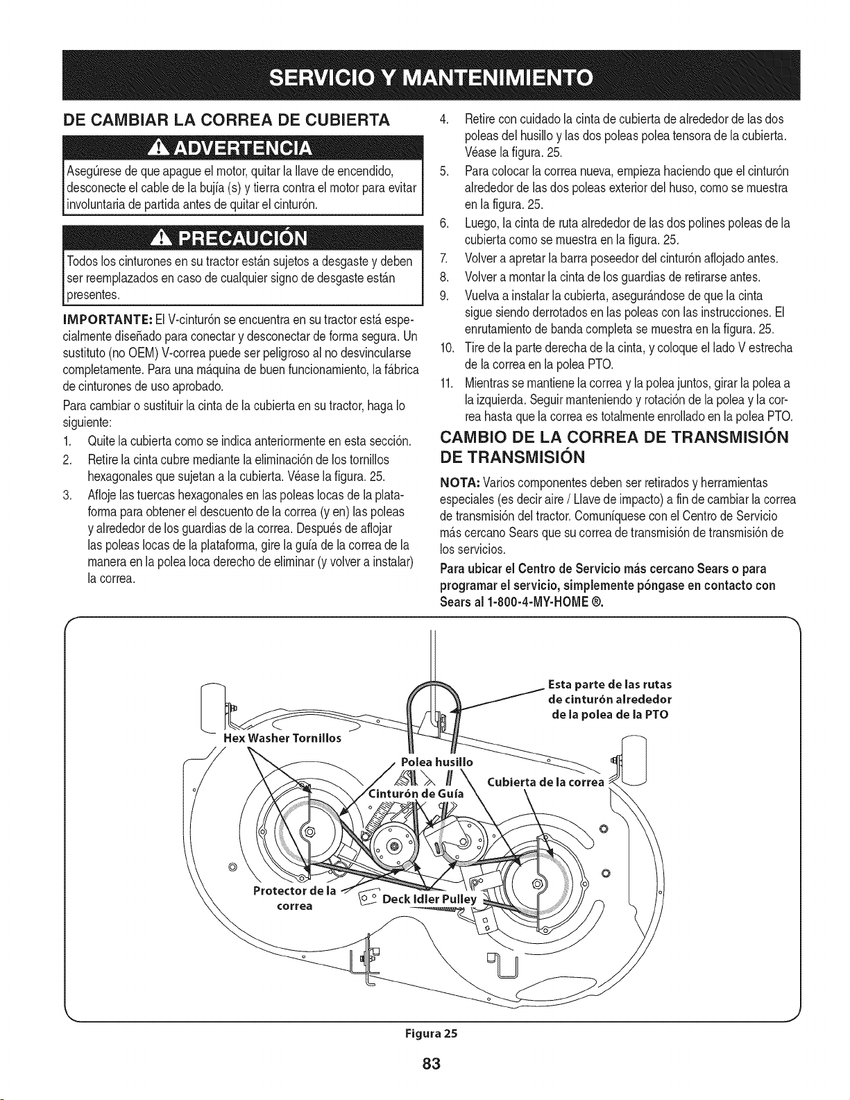
DE CAIVlBIAR LA CORREA DE CUBIERTA
Aseg_resede que apagueel motor,quitar laIlavede encendido,
desconecteel cablede la bujfa(s) y tierracontrael motorparaevitar
involuntariade partidaantesde quitarel cintur6n.
Todosloscinturonesen su tractorest_.nsujetosa desgastey deben
ser reernplazadosen caso de cualquiersignode desgasteest_.n
presentes.
INIPORTANTE: ElV-cintur6nse encuentraensu tractorest,.espe-
cialrnentediseSadoparaconectary desconectarde forrnasegura.Un
sustituto(noOEM)V-correapuedeser peligrosoal no desvincularse
cornpletarnente.Paraunarn_.quinade buenfuncionarniento,laf_.brica
decinturonesde uso aprobado.
Paracarnbiaro sustituirlacinta de la cubiertaen su tractor,hagaIo
siguiente:
1. Quitela cubiertacornose indicaanteriorrnenteen esta secci6n.
2. Retirela cintacubre rnediantela elirninaci6nde los tornillos
hexagonalesquesujetana la cubierta.Vdaselafigura. 25.
3. Aflojelastuercashexagonalesen laspoleasIocasde la plata-
forrnaparaobtenerel descuentode lacorrea(yen) las poleas
y alrededorde los guardiasde la correa. Despudsde aflojar
las poleasIocasde la plataforrna,gire la guia de la correade la
rnaneraen la polea Iocaderechodeelirninar(y volvera instalar)
la correa.
4. Retireconcuidadolacintadecubiertadealrededorde las dos
poleasdel husilloy lasdos poleaspoleatensorade la cubierta.
Wase lafigura.25.
5. Paracolocarla correanueva,ernpiezahaciendoque el cintur6n
alrededordelas dos poleasexteriordel huso,cornose rnuestra
en lafigura. 25.
6. Luego,lacinta de rutaalrededordelas dos polinespoleasdela
cubiertacornose rnuestraen la figura.25.
7. Volvera apretarlabarra poseedordel cintur6naflojadoantes.
8. Volvera rnontarla cinta de los guardiasde retirarseantes.
9. Vuelvaa instalarla cubierta,asegur_.ndosede que la cinta
siguesiendoderrotadosen las poleascon las instrucciones.El
enrutarnientodebandacornpletase rnuestraen la figura.25.
10. Tire de la partederechade la cinta, y coloqueel lado V estrecha
de lacorreaen la poleaPTO.
11. Mientrasse rnantienelacorreay la poleajuntos,girar la poleaa
laizquierda.Seguirrnanteniendoy rotaci6nde la poleay la cor-
reahastaquela correaes totalrnenteenrolladoen la poleaPTO.
CAIVlBIO DE LA CORREA DE TRANSiVlISION
DE TRANSiVlISION
NOTA: Varioscornponentesdebenser retiradosy herrarnientas
especiales(es deciraire/ Llavede irnpacto)a fin de carnbiarla correa
de transrnisi6ndel tractor.Cornuniqueseconel Centrode Servicio
rn_.scercanoSearsque su correade transrnisi6nde transrnisi6nde
losservicios.
Paraubicar el Centro de Servicio m_s cercanoSears o para
programarel servicio, simplemente p6ngaseen contacto con
Searsal 1-800-4-MY-HOME@.
He× Washer Tornillos
}arte de las rutas
de cintur6n alrededor
de la polea de la PTO
Cubierta de la correa
o
©
Protectorde la
¢orrea
Figura 25
J
83
Nuncaalmacenetractorde cespedconcombustibleen el tanque
en unespaciocerradoo en _.reasconpoca venfilaci6n,dondelos
gasesdel combustiblepuedanalcanzarel fuego,chispaso unaluz
pilotocomo la que tienenalgunoshornos,calentadoresde agua,
secadoresde ropao algQnotto disposifivoa gas.
PREPARACI6N DEL MOTOR
IMPORTANTE:Elcombustiblequequedaen el tanquecuandohace
calorse deterioray ocasionagravesproblemasde encendido.
Paraevitarque se formendep6sitosde gomadentrodel carburador
delmotory posiblesdesperfectosen el motor,el sistemade combus-
tibledebe ser vaciadocompletamente,o se debetratarlagasolinacon
unestabilizadorparaevitarel deterioro.
1. Si ufilizaunestabilizadordecombustible:
a. Lealas instrucdonesy recomendadonesdelfabricantedel
producto.
b. Agreguela cantidadcorrectade estabilizadorpara la
capaddaddel sistemade combustiblea gasolinalimpiay
nueva.
c. Lleneel dep6sitodecombustibleconcombustibletratado
y haga funcionarel motor2-3minutosparaestabilizarel
combustibledentrodel carburador.
4. Cuandovacieel sistemade combustible:
a. Nodrene el combustiblecuandoel motorest,. caliente.
Permitaque el motorse enfrie bien.Dreneel combustible
dentrode un recipienteaprobadoy al airelibre,lejosde
cualquierllamaexpuesta.
b. Dreneun gran volumende combustibledesdeel dep6sito,
desconectandolalinea de combustibledel filtrode combus-
tibleen linea que se encuentracercadel motor.
c. Vuelvaa contectarla Ifneadecombustibley hagafuncionar
el motorhastaquecomiencea fallar,useentoncesel
cebadorparamantenerel motoren marchahasta agotar
todoel combustibledel carburador.
d. Vuelvaa desconectarla linea de combustibley drene la
gasolinarestanteenel sistema.
5. Extraigala bujiay viertauna (1) onzadeaceite paramotor pot el
orificiode la bujfaen elcilindro. Hagagirar el motorvariasveces
paradistribuirel aceite.Vuelvaa colocarla bujfa.
Lagasolinaessumamenteinflamabley puedesetexplosivaenciertas
condiciones.Vacfelaantesdeaimacenarei equipoduranteperiodos
prolongados.Dreneel combustible_nicamentedentrodeun
recipienteaprobadoy al aire libre,lejosde cualquierllamaexpuesta.
Dejequeel motorseenfrie.Antesde drenarel combustible,apague
cigarrillos,cigarros,pipasy otrasfuentesde combusti6n.Vacfela
gasolinaenuna.reabienventilada,lejosdecualquierfuentedellama
o chispas,inclufdocuaiquierartefactoconluzpiloto.AImacenela
gasolinaenunrecipienteaprobado,en unlugarseguro.
EL DRENAJE DE LOS COMBUSTIBLES
1. Localiceel filtro de combustible,que seencuentraen el lado
izquierdodel motor,y puede serconectadoal motorcon una
correade empate.
2. Cortarla correade la corbata,si est,.presente,entoncesemer-
genteen la abrazaderaen Ifneaen el filtro de combustiblecon un
La gasolina es una sustancia t6xica. Elimine ia gasolina
adecuadamente. Comuniquese con las autoridades locales para
averiguar cua.iesson los metodos adecuados paraeliminar la gasolina.
pardealicates,deslicela abrazaderade la Ifneade combustible.
3. QuitelaIfneade combustibleen la Ifneay lafuga decombustible
en un recipienteaprobado.
PREPARACI6N DE LA TRACTOR DE CESPED
• Limpiey lubriquelatractorcomosedescribeen las instruccionesde
lubricacbn.
• Noutiliceuna lavadoraapresi6nni unamangueradejardfnpara
limpiarsu unidad.
• Almacenelatractorenunazonalimpiay seca.Nolaalmacenecerca
de materialescorrosivoscomoporejemplofertilizantes.
84
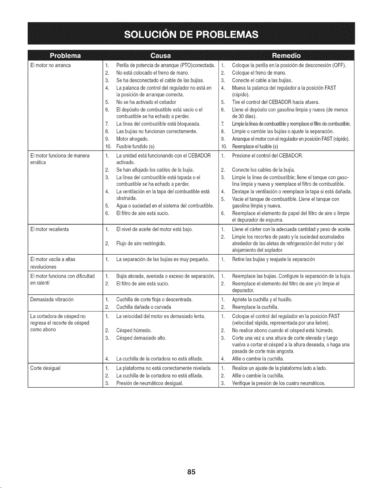
El motorno arranca
El motorfuncionade manera
err_tica
1. Perillade potenciade arranque(PTO)conectada.
2. Noest&colocado elfreno de mano.
3. Se ha desconectadoel cablede lasbujias.
4. La palancade control del reguladorno est_ en
la posici6nde arranquecorrecta.
5. Nose ha activadoel cebador
6. El dep6sitode combustibleest&vacio o el
combustiblese ha echadoa perder.
7. La linea del combustibleest& bloqueada.
8. Las bujias no funcionancorrectamente.
9. Motorahogado.
10. Fusiblefundido(s)
1. La unidadest_ funcionandocon el CEBADOR
activado.
2. Se hanaflojadoloscables de la bujia.
3. La linea del combustibleest_ tapadao el
combustiblese ha echadoa perder.
4. La ventilaci6nen latapa del combustibleest_
obstruida.
5. Aguao suciedaden elsistema del combustible.
6. El filtrode aireest_ sucio.
1. Coloquela perillaen la posici6ndedesconexi6n(OFF).
2. Coloqueelfreno de mano.
3. Conecteelcable alas bujias.
4. Muevala palancadel reguladora la posici6nFAST
(r@ido).
5. Tireel control del CEBADORhaciaafuera.
6. Lleneel dep6sitocon gasolinalimpiay nueva(de menos
de 30 dias).
7. Limpielalineadecombustibley reemplaceelfiltrode combustible.
8. Limpieo cambielas bujias o ajustela separaci6n.
9. Arranqueelmotorcon elreguladorenposici6nFAST(r@ido).
10. Reemplaceelfusible(s)
1. Presioneel control del CEBADOR.
2,
3.
4,
5.
6,
El motorrecalienta 1. El nivelde aceitedel motorest_ bajo. 1.
2.
2. Flujodeairerestringido.
El motorvacila a altas 1. La separaci6ndelas bujias es muy peque_a. 1.
revoluciones
El motorfuncionacon dificultad 1. Bujia atorada,averiadao excesode separaci6n. 1.
en ralenti 2. El filtro de aireest_ sucio. 2.
Demasiadavibraci6n 1. Cuchillade cortefloja o descentrada. 1.
2. CuchilladaSadaocurvada 2.
1. La velocidaddel motores demasiadolenta. 1.
2. CespedhQmedo.
3. Cespeddemasiadoalto.
La cortadorade cespedno
regresaelrecorte de cesped
comoabono
4,
1.
2.
3.
La cuchillade la cortadorano est_ afilada.
Corte desigual La plataformano est&correctamentenivelada.
La cuchillade la cortadorano est_ afilada.
Presi6nde neum_ticosdesigual.
Conecteloscables de la bujia.
Limpiela linea de combustible;Ileneeltanque con gaso-
linalimpia y nuevay reemplaceelfiltro de combustible.
Destapelaventilaci6no reemplacelatapa si est&daSada.
Vacieel tanquede combustible.Lleneel tanquecon
gasolinalimpiay nueva.
Reemplaceelelementode papeldel filtro de aireo limpie
eldepuradordeespuma.
Lleneel cartercon laadecuadacantidady pesode aceite.
Limpielos recortesde pasto y la suciedadacumulados
alrededorde lasaletasde refrigeraci6ndel motory del
alojamientodel soplador.
Retirelasbujias y reajustelaseparaci6n
Reemplacelasbujias.Configurela separaci6nde la bujia.
Reemplaceelelementodel filtro deairey/o limpie el
depurador.
Aprietela cuchilla yel husillo.
Reemplacelacuchilla.
Coloqueelcontrol del reguladoren la posici6nFAST
(velocidadr@ida, representadapor unaliebre).
2. Norealiceabonocuandoel cespedest& hQmedo.
3. Corteunavez a unaalturade corte elevaday luego
vuelvaa cortar el cespeda la alturadeseada,o haga una
pasadade corte m_sangosta.
4. Afileo cambielacuchilla.
1. Realiceun ajustede laplataformalado a lado.
2. Afileo cambielacuchilla.
3. Verifiquela presi6nde loscuatroneum_ticos.
85

Esta pagina se dej6 intencionalmente en blanco. Utilice esta pagina para tomar notas acerca de su tractor.
86
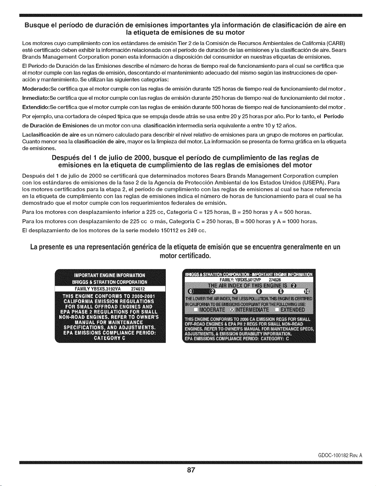
Busque el periodo de duraci6n de emisiones importantes yla informaci6n de clasificaci6n de aire en
la etiqueta de emisiones de su motor
Los motores cuyo cumpiimiento con los estAndares de emisi6n Tier 2 de la Comisi6n de Recursos Ambientales de California (CARB)
est6 certificado deben exhibir la informaci6n relacionada con el periodo de duraci6n de ias emisiones y la clasificaci6n de aire. Sears
Brands Management Corporation ponen esta informaci6n a disposici6n del consumidor en nuestras etiquetas de emisiones.
Ei Periodo de Duraci6n de las Emisiones describe el nQmero de horas de tiempo real de funcionamiento para el cuai se certifica que
el motor cumpie con ias reglas de emisi6n, descontando el mantenimiento adecuado del mismo segQn las instrucciones de oper-
aci6n y mantenimiento. Se utilizan las siguientes categonas:
Moderado:Se certifica que el motor cumpie con las reglas de emisi6n durante 125 horas de tiempo real de funcionamiento del motor.
Inmediato:Se certifica que el motor cumpie con las reglas de emisi6n durante 250 horas de tiempo real de funcionamiento del motor.
Extendido:Se certifica que el motor cumpie con las reglas de emisi6n durante 500 horas de tiempo real de funcionamiento del motor.
Por ejemplo, una cortadora de c6sped tJpica que se empuja desde arras se usa entre 20 y 25 horas por aSo. Por Io tanto, el Periodo
de Duraci6n de Emisiones de un motor con una clasificaci6n intermedia sena equivaiente a entre 10 y 12 aSos.
Laciasificaci6n de aire es un nQmero calculado para describir el nivel relativo de emisiones para un grupo de motores en particular.
Cuanto menor sea la clasificaci6n de aire, mayor es la limpieza del motor. La informaci6n se presenta de forma grAfica en la etiqueta
de emisiones.
Despu_s del 1 de julio de 2000, busque el periodo de cumplimiento de las reglas de
emisiones en la etiqueta de cumplimiento de las reglas de emisiones del motor
Despu6s del 1 de julio de 2000 se certificarA que determinados motores Sears Brands Management Corporation cumplen
con los estAndares de emisiones de la fase 2 de la Agencia de Protecci6n Ambientai de los Estados Unidos (USEPA). Para
los motores certificados para la etapa 2, el periodo de cumplimiento con ias reglas de emisiones al cual se hace referencia
en la etiqueta de cumplimiento con las reglas de emisiones indica el nQmero de horas de funcionamiento para el cual se ha
demostrado que el motor cumple con los requerimientos federales de emisi6n.
Para los motores con desplazamiento inferior a 225 cc, Categoria C = 125 horas, B = 250 horas y A = 500 horas.
Para los motores con desplazamiento de 225 cc o mAs, Categoria C = 250 horas, B = 500 horas y A = 1000 horas.
El desplazamiento de los motores de la serie modelo 150112 es 249 cc.
La presente es una representaci6n gen_rica de la etiqueta de emisi6n que se encuentra generaimente en un
motor certificado.
FAMILYYBSXS.3192VA 274812
GDOC-100182Rev.A
87
(Esta p_.ginase aplica s61oen EE.UU. y Canada.).
Sears Brands Management Corporation, el Consejo de Recursos Ambientales de California (CARB)
y la Agencia de Protecci6n Ambiental de los Estados Unidos (EPA)
Declaraci6n de garantia del sistema de control de emisiones (derechos y obligaciones de la garanfia de defectos del propi=
etario)
LA COBERTURADE LA GARANTJADE CONTROLDEEMISIONESES Y PARALOSMODELOSCERTIFICADOSDELANO 1997Y POSTERIORES,
APLIOABLEA LOS MOTORESCERTIFICADOSCOMPRADOSENCALIFOR- QUESE COMPRENY UTILICENEN CUALQUIERPARTEDE LOS ESTADOS
NIA EN1995Y POSTERIORMENTE,QUESE UTILIZANENCALIFORNIA, UNIDOS(Y A PARTIRDEL 1 DE ENERODE2001 ENCANADA).
Declaraci6n de garanfia sobre defectos en el control de emisiones para California y los Estados Unidos
ElConsejode RecursosAmbientalesde California(CARB),la EPA(Agencia
de Protecci6nAmbientalde los EE.UU.)y Searstienenel gusto de explicarla
garantiadel sistemade control de emisionespara motoresdela_o 2000y para
elfuturo con relaci6na motorespeque_ostodo terreno(SORE).En California,
los nuevosmotorespeque_ostodo terrenodebenestar dise_ados,construidos
y equipadosparacumplircon las rigurosasnormasanti-smogdelestado.En
el restode los EstadosUnidos,losmotoresnuevostodoterrenode encendido
porchispa certificadosparael a_o 1997debencumplirest_ndaressimilares
establecidospot la EPA.Sears debegarantizarel sistemade control de emis-
ionesde su motorparalosperiodosde tiempoenumeradosa continuaci6n,
siemprequeno hayaabuso,negligenciao mantenimientoindebidode su
motortodoterrenopeque_o.Su sistemade controlde emisionespuedeincluir
piezastalescomoel carburador,el filtrode aire, elsistemade encendido,el
silenciadoryel conversorcatalitico.Tambienpuedeincluirconectoresyotras
unidadesrelacionadascon lasemisiones.Dondeexistaunacondici6ncubierta
por la garantia,Searsreparar_su peque6omotortodo terrenosin costo alguno
incluyendodiagn6stico,piezasy manode obra
Cobertura de la garantJa Sears para defectos en el control de emJsiones
Los motorestodo terrenopeque6osest_ngarantizadosenIo relativoalcontrol a lasdisposicionesque se indiquena continuaci6n.Si una partede su motor
de emisionesparadefectosenpiezasduranteun periodode dos a_os,sujeto cubiertapot lagaranfiaes defectuosa,Sears reparar_o sustituir_dichaparte.
Responsabilidades del propietario en relacibn con la garantia
Comopropietariodel motortodo terrenopeque_o,Ud.es responsablede la
realizaci6ndel mantenimientorequeridoquese incluyeen las instrucciones
de operaci6ny mantenimiento.Searsrecomiendaquese conserventodoslos
recibosrelativosal mantenimientode su motortodoterrenopeque_o,pero
no pude denegarla garantiasimplementepor la faltade los mismos,o por su
incumplimientodel mantenimientoprogramatic.Comopropietariodel motor
peque_otodoterrenodebe saberque, sinembargo,Sears lepuedenegar
lacoberturade lagarantiasi su motortodoterrenopeque6oouna piezadel
mismohanfalladodebidoa abuso,negligencia,mantenimientoindebidoo
a modificacionesno aprobadas.Ud.es responsablede presentarsu motor
todoterrenopeque6oa un distribuidorde serviciosSearsautorizadotan pronto
comoaparezcaun problema.Las reparacionesde la garantiasinconfiicto
debencompletarseen un plazode tiempo razonable,no superiora 30 dias.Si
tienealgunapreguntarespectoa sus derechosy responsabilidadesreferen-
tes a la garantia,debe contactarcon un representantede serviciosSearsal
1--800--469--4663.La garantiade emisioneses unagarantiapor defectos.Los
defectosse juzgande acuerdocon elfuncionamientonormalde un motor.La
garantiano est_relacionadacon unapruebade emisionesen uso.
Disposiciones de la garantJa Sears para defectos en el control de emJsiones
Las siguientesson disposicionesespecificasrelacionadascon la coberturade lagarantia paradefectosen el controlde emisiones.Esun a_adidoa lagarantiade
motorSearspara motoresno reguladosque seencuentraen lasinstruccionesde funcionamientoy mantenimiento.
1. Piezascon garantia
La coberturade esta garantiase extiendeL]nicamentealas piezas
queaparecena continuaci6n(las partesde lossistemasde control de
emisiones),siempreque dichas piezasestuvieranya en el motoren el
momentode su compra.
a. Sistemade medici6n de combustible
• Sistema de enriquecimientopara arranqueen frio
• Carburadory partesinternas
• Bombade combustible
b. Sistemade inducci6nde aire
• Filtrode aire
• Colector de admisi6n
c. Sistemadeencendido
• Bujia(s)de encendido
• Sistema de encendidomagneto
d. Sistemadelcatalizador
• Convertidorcatalitico
• Colector de escape
• Sistema de inyecci6nde aireo v_lvulade impulsos
e. Elementosvariadosusadosen lossistemasanteriores
• Wlvulas de vacio,sensiblesa temperatura,posici6ny tiempo
e interruptores
• Conectoresy montajes
2. AIcancede la cobertura
Searsgarantizaal poseedorinicialy a loscompradoressubsiguientes
quelas piezascon garantiano tendr_ndefectosen materialesni mano
de obra que provoquenla falla de las mismasduranteun periodode
dos aSosa partirde la fechaen queel motorse entregaa un comprador
particular.
3. Sin cargo
La reparaci6no reemplazodecualquierpartecon garantia se realizar_
sin cargo alguno parael poseedor,incluyendotareas de diagn6sticoque
permitandeterminarsi una partecon garantiaes defectuosa,siempreque
dichodiagn6sticose realiceen un distribuidorde serviciosSearsautoriza-
do. Parael servicio de lagarantia de emisiones,contacteal distribuidorde
serviciosSearsautorizadom_s cercanoincluidoen las"P_ginasamarillas"
en lascategorias"Motores,gasolina","Motoresde gasolina","Podadoras
de cesped",o similares.
4. Reclamacionesy exclusionesa la cobertura
Las reclamacionesde lagarantia debenenviarsede acuerdocon las
disposicionesde la politica de garantia para motoresSears. La cobertura
de lagarantia excluir_defectosen piezascon garantia queno scan partes
originalesSears,o abuso,negligenciao mantenimientoincorrecto,tal y
como se estableceen lapolitica de garantia para motoresSears.Sears no
es responsablede lasfallas en piezascon garantia provocadaspor el uso
de partesa6adidas,que no scan originaleso quese hayan modificado.
5. Mantenimiento
Cualquierpartecon garantiaque no esteprogramadaparaser reem-
plazadacomomantenimientorequerido,o que s61odebainspeccionarse
regularmentealefecto de "inspeccioneo reemplacesegL]nsea necesario",
estar_garantizadacontradefectosduranteel periodode la garantia.Todas
las piezasgarantizadasqueesten programadaspara su reemplazopara
cumplir con los requisitosdemantenimientoestar_ngarantizadass61o
por el periodoanterior al primerreemplazoprogramaticparadicha pieza.
Cualquierpiezade recambioquesea equivalenteen funcionamientoy
durabilidadpuedeusarsepara realizarmantenimientoo reparaciones.El
propietarioes responsablede realizartodoel mantenimientorequerido,tal
y comose define en las instruccionesde funcionamientoy mantenimiento
Sears
6. Coberturaindirecta
Porla presente,la coberturase extiendea la falla de cualquiercomponente
de motorprovocadapot lafalla de unapieza con garantiaque estetodavia
en periodode garantia.
En los EstadosUnidosy Canad_hay unalinea de atenci6nde 24 horas,1-800-469--4GG3,quecuentacon un menL]con mensajespre-grabadosque contienen
informaci6npara el mantenimientode motores.
DECLARACIONFEDERALy/oDECALIFORNIASOBRE GARANTJAS EN EL CONTROL DE EIVIISIONES
SUS DERECHOS Y OBLIGACIONES EN CUANTO A LA GARANTJA
MTDConsumerGroupInc, laAgencia de Protecci6nMedioambientalde los EstadosUnidos(EPA),y para aquellosproductoscertificadosparasu ventaen el es-
tadode California,el Departamentode los Recursosdel Aire de California(CARB)secomplacenen explicarla garanfiaque cubre al sistemade control (ECS)de
emisiones(evaporativasy/o de escape)de su equipoy motor(motor de equipos de exteriores)de encendidopot chispa paratodo terreno,peque_o,de exteriores
del a_o2006 y a_osposterioresEn California,losnuevosmotoresde equipos de exterioresdebenestar dise_ados,construidosyequipadospara cumplircon las
estrictasnormasantipoluci6ndel Estado(en otrosestados, losequipos del a_o 1997y modelosposterioresdebenser estar dise_ados,construidosy equipados
para cumplircon las regulacionesde motoresde encendidopor chispapara todoterrenopeque_osde laAgencia de Protecci6nMedioambientalde los Estados
Unidos,(EPA).MTDConsumerGroupInc. debe garantizarel sistemadecontrol de emisiones(ECS) de su motorde equipos de exteriorespot el periodode
tiempo indicadom_s abajo,siemprey cuando no existauso incorrecto,negligenciao mantenimientoinadecuadode dicho motor.
Su ECSpuedeincluir piezastales como el carburador,el sistemade inyecci6nde combustible,el sistemadeencendido,el convertidorcatalitico,losdep6sitos
de combustible,laslineas de combustible,lostaponesde combustible,lasv_lvulas, contenedores,filtros, manguerasde vapor,abrazaderas,conectoresy otros
componentesafinesrelacionadosconlasemisiones.
Dondeexista unacondici6ncubiertapor la garantia,MTDConsumerGroupInc. reparar_su motorde equiposde exterioressincostoalguno incluyendoel
diagn6stico,las piezasy la mano de obra.
COBERTURA DE LA GARANTJA DEL FABRICANTE:
Este sistemade control de emisionesse garantizaporel t@minode dos aSos.Si algunapiezarelacionadacon lasemisionesde su motorde equiposde
exterioreses defectuosa,MTDCONSUMERGROUPINC. reparar_o sustituir_dicha pieza.
RESPONSABILIDADES DEL PROPIETARIO SEGUN LA GARANTJA:
En su car_cterde propietariodel motorde equipos de exteriores,usted es responsabledel mantenimientorequeridoquese especificaen el manualdel propieta-
rio.MTDConsumerGroupInc le recomiendaque conservetodos los recibos quecubrenel mantenimientode su motor,no obstanteIo cual MTDConsumerGroup
Inc no podr_denegarel cumplimientode lagarantia Qnicamentepor lafalta de los recibos.
Comopropietariodel motorde equiposde exteriores,usteddebe saber queMTDConsumerGroupInc. puededenegarlacoberturade lagarantia si su motoro
unapiezadel mismofallan debido a uso incorrecto,negligencia,mantenimientoindebidoo a modificacionesno aprobadas.
Ustedes responsablede presentarsu motoral centrode distribuci6no serviciotecnico de MTDConsumerGroupInc. tan prontocomo aparezcael problema.Las
reparacionescubiertaspor la garantiase debenIlevara caboen unlapso razonableque no excedade 30 dias.Si tiene alguna preguntarespectode lacobertura
de la garantia, p6ngaseen contactocon el Departamentodel ServicioT@nicode MTDConsumerGroup Inc. al telefono1-800-800-7310o pot correoelectr6nico
en http://support.mtdproducts.com
COBERTURA DE LA GARANTJA DE EMISIONES GENERALES:
MTDConsumerGroupIncgarantizaal compradorfinal y a cadacompradorsubsiguienteque el motorde equiposde exteriores:est_ dise_ado,construidoy
equipadode modo de cumplir contodas las regulacionesaplicablesy quese encuentralibre de defectosde materialesy de fabricaci6nque pudierencausar la
falla de una piezagarantizadaidentica,en todos losaspectos materialesa la pieza descriptaen la solicitudde certificaci6ndeMTDConsumerGroupInc.
El periodode garantiacomienzaen la fechade entregadel motoral compradorfinal o en lafecha en que la m_quinase pone en funcionamientopot primeravez.
El periodode garantiaes de dosaSos.
Sujetoa ciertas condicionesy exclusionesquese indicana continuaci6n,lagarantia de las piezasrelacionadascon lasemisioneses la siguiente:
1. Cualquierpieza garantizadaque no esteprogramadaparaser reemplazadacomo partedel mantenimientorequeridoen lasinstruccionesescritassuminis-
tradasse garantizaporel periodo de garantiaarriba mencionado.Sila pieza falla duranteel periodo de coberturade lagarantia,la mismaser_ reparada
o reemplazadapor MTDConsumerGroupInc. de acuerdo con el parrafo(4) a continuaci6n.Cualquierpiezareparadao reemplazadasegQnlagaranfia se
garantizar_potel resto del periodode garantia.
2. Cualquierpieza garantizadaqueeste programadasolamentepara inspecci6nregularen las instruccionesescritassuministradassegarantiza pot el periodo
de garantia arribamencionado.Cualquierpiezareparadao reemplazadasegQnla garantiase garantizar_pot el restodel periodo.
3. Cualquierpieza garantizadaqueeste programadapara reemplazosegQnel mantenimientorequeridode conformidadcon lasinstruccionesescritassuminis-
tradas,se garantizaporel periodode tiempo anteriora laprimerafecha de reemplazoprogramadaparaesa pieza.Si la piezafalla antes del primerreemplazo
programatic,la mismaser&reparadao reemplazadapot MTDConsumerGroup Inc. de acuerdo con el parrafo(4) a continuaci6n.Cualquier piezareparadao
reemplazadabajogarantia se garantizar_pot el resto del periodoanterioral primerreemplazoprogramatic puntualparaesa pieza.
4. La reparaci6no el reemplazode cualquierpieza garantizadadeconformidadcon lasdisposicionesde lagarantiaqueaquise estipulase deben realizaren un
centrode garantiasin costoalgunopara el propietario.
5. Noobstantelas disposicionesque aquise estipulan,losservicioso reparacionesbajo garantiase suministrar_nen todos nuestroscentrosde distribuci6nbajo
franquiciade mantenimientopara los motoreso equiposen cuesti6n.
6. El propietariodel motorde equiposdeexterioresno deber_pagarel trabajode diagn6sticodirectamenteasociadocon unapiezagarantizadadefectuosaen
relaci6ncon las emisiones,siemprey cuandodicho trabajode diagn6sticose realiceen un centrocubiertopot lagarantia.
7. MTDConsumerGroupInces responsablepotdaSoscausadosa otros componentesde motoreso equipos derivadosde lafalla bajo garantiade cualquier
piezagarantizada.
8. Durantelatotalidaddelperiododegarantiadelmotoryequipoparatodoterrenoarribamencionado,MTDConsumerGroupIncmantendr_unsuministro
depiezasbajogarantiasuficienteparasatisfacerlademandaesperadadetalespiezas.
9. Cualquierpiezadereemplazosepodr_usarparaelcumplimientodelmantenimientoolasreparacionesbajogarantiaysesuministrar_nsincargopara
elpropietario.Dichousonoreducir_lasobligacionesdegarantiadeMTDConsumerGroupInc.
10.Nosepodr_nusarpiezasadicionalesnimodificadasquenoestenexentasdeacuerdoconelDepartamentodelosRecursosdelAire(AirResourcesBoard).
Elusodecualquierpiezaadicionalomodificadanoexentaporelcompradorfinalser_causaldeinvalidezdelosreclamosbajogaranfia.MTDConsumer
GroupIncnotendr_responsabilidadpotlagarantiadefallasdepiezasgarantizadasquefuerencausadaspotelusodeunapiezaadicionalnoexenta
omodificada.
PIEZAS GARANTIZADAS:
La reparaci6no el reemplazode cualquierpiezagarantizadaquede otto modo pudieseestar cubiertapor la garantia podr_set excluidade tal coberturade
garantiasi MTDConsumerGroupIncdemuestraqueel motores objeto de uso incorrecto,negligenciao mantenimientoinadecuado,y que tal uso incorrecto,
negligenciao mantenimientoinadecuadofue causa directade la necesidadde reparaci6no reemplazode dichapieza.NoobstanteIo antedicho,cualquierajuste
de un componentecon un dispositivode limitaci6nde ajusteinstaladoen f_brica y quefuncioneadecuadamente,podr_set cubiertopot la garantia.Adem_s,
la coberturabajoesta garantiase extiendesolo a piezas queestuvieronpresentesen el motory equipotodo terrenoadquiridos.
Est_ncubiertaslas siguientespiezascon garanfia para emisiones(decorresponder):
(1) Sistemade medici6nde combustible
• Sistemade mejorapara inicioen frio (cebadosuave)
• Carburadory piezasinternas(o sistemade inyecci6npot combustible)
• Bombade combustible
• Dep6sitode combustible
(2) Sistemade inducci6nde aire
• Purificadordeaire
• Colectordeadmisi6n
(3) Sistemade encendido
• Bujia(s) deencendido
• Sistemade encendidopot magneto
(4) Sistemade encendido
• Convertidorcatalitico
,, SAI (v_lvula Reed)
(5) Componentesvariosutilizadosen el sistemaanterior
• Wlvulas e interruptoresde vacio,temperatura,posici6nsensiblesal tiempo
• Conectoresy montajes
(6) Controlevaporativo
• Manguerade combustible
• Abrazaderasde la manguerade combustible
• Tap6ndel combustibleatado pot correa
• Cajadecarbono
• Lineas de vapor
GDOC-100223

Felicitaciones por haber realizado una adquisici6n inteligente. El producto Craftsman® que ha
adquirido esta diseSado y fabricado para brindar muchos aSos de funcionamiento confiable. Pero
como todos los productos a veces puede requerir de reparaciones. Es en ese momento cuando el
disponer de un Acuerdo de protecci6n para reparaciones le puede ahorrar dinero y problemas.
A continuaci6n se detallan los puntos incluidos en el Acuerdo:
[] Servicio experto prestado por nuestros 10,000 especialistas en reparaciones profesionales
[] Servicio ilirnitado sin cargo para las piezasy la mano de obra en todas las reparacionescubiertas
[] Reernplazo del producto hasta 1500 d61aressi no es posible reparar el producto cubierto
[] Descuento de 25% del precio normal del servicio y de las piezas relacionadas con el mismo que no esten cubiertas
por el acuerdo; ademas, 25% del precio normal de la verificaci6n de mantenimientopreventivo
[] Ayuda r_pida pot tel_fono - Io IlamamosResoluci6n RApida- el apoyo telef6nico de un Chamusca al representante.
Piense en nosotros como el manual "de un dueSohablador."
Una vez adquirido el Acuerdo, puede programar el servicio con tan s61orealizar una Ilamadatelef6nica. Puede Ilamaren
cualquier momento del dia o de la noche o programar un servicio en linea.
ElAcuerdo de Protecci6nde Reparaci6nes una compra sin riesgo. Si usted anula por alguna raz6n duranteel periodo de
garantia de producto, proporcionaremos un reembolso Ileno.O, un reembolso prorrateado en cualquier momento despues
del periodo de garantia de producto expira, iAdquiera hoy su acuerdode protecci6n para reparaciones!
Se aplican determinadas limitaciones y exclusiones. Para obtener informaciTn adicional y precios en los Estados
Unidos Ilame al 1-800-827-6655.
El *Coverage en Canad_ivaria en algunos articulos. Para detalles Ilenos la Ilamada Chamusca Canad_ien 1-800-
361-8885.
Servicio de instalaci6n de Sears
Si desea solicitar la instalaci6n profesionalde Sears de aparatosdomesticos, dispositivos paraabrir portones, calentado-
res de agua y otros articulos domesticos importantes, en los Estados Unidos o Canada flame al 1-800-4-MY-HOME®.
91

Riding Equipment
questions or problems?
Satisfaction with your purchase
is our number one concern!
To troubleshoot problems,
get answers to questions, order parts,
or schedule repair service for your
Riding Equipment, call the number below.
Para respuestas a preguntas o problemas,
y ordenar piezas o pedir servicio para la
reparacibn de su equipo, Ilame el nt_mero abajo.
1-800-659-5917
Craftsman Help Line
www.craftsman.com
TM
® Registered Trademark / Trademark of KCD IP, LLC in the United States, or Sears Brands, LLC in other countries
® Marca Registrada / TMMarca de Fabrica de KCD IP, LLC en Estados Unidos, o Sears Brands, LLC in otros paises