
perator's
nual
I:RnFrSMRN°
LAWN TRACTOR
21 HP, Variation Speed
46" Deck
Model No. 247.288862
• Espanol, P. 58
This product has a low emission engine which operates differently
from previously built engines. Before you start the engine, read and
understand this Operator's Manual.
Before using this equipment,
read this manual and follow
all safety rules and operating
instructions.
For answers to your questions about
this product, call:
1-800=659=5917
Craftsman Tractor Help Line
7 am = 7 pm CT, Mort. =Sun.
Sears Brands Management Corporation, Hoffman Estates, IL 60179 U.S.A.
Visit our website: www.craftsman.com FormNo.769-06502E
(December6,2012)
Warranty Statement .......................................................... 2
Safety Instructions ............................................................ 3
Slope Gauge ..................................................................... 8
Assembly ........................................................................... 9
Operation ........................................................................ 11
Service and Maintenance .............................................. 17
Off-Season Storage ........................................................ 26
Trou bleshooting .............................................................. 27
Labels ............................................................................. 28
Parts List ......................................................................... 30
Espa_ol ............................................................................ 58
Service Numbers ............................................. Back Cover
CRAFTSMAN FULL WARRANTY
FORTWOYEARSfromthe dateof purchase,all non-expendablepartsof this ridingequipmentarewarrantedagainstany defectsinmaterialor
workmanship.A defectivenon-expendablepartwill receivefree in-homerepairor replacementif repairis unavailable.
BATTERYLIMITEDWARRANTY
FOR90 DAYSfromthe dateof purchase,the battery(an expendablepart)of this ridingequipmentiswarrantedagainstanydefectsinmaterialor
workmanship.A newbatterywill besuppliedfreeof charge.Youareresponsiblefor the laborcostof batteryinstallation.
ADDITIONALLIMITEDWARRANTIES
inthe followingadditionalwarranties,you are responsibleforthe laborcost of partinstallationafterthe secondyearfromthe dateof purchase.
FORFiVEYEARSfrom thedateof purchase,the frameof this ridingequipmentiswarrantedagainstanydefects inmaterialor workmanship.A
newframewill be suppliedfreeof charge.
FORTENYEARSfromthe dateof purchase,the frontaxleof thisriding equipmentiswarrantedagainstany defectsinmaterialorworkmanship.
A newfrontaxle will be suppliedfreeof charge.
FORASLONGAS IT iSUSEDbytheodginalownerafterthetenthyearfromthedateof purchase,thecastironfrontaxle(if equipped)ofthis riding
equipmentiswarrantedagainstanydefectsinmaterialorworkmanship.Withproofofpurchase,a newcastironfrontaxlewillbesuppliedfreeofcharge.
WARRANTYSERVICE
Forwarrantycoveragedetailsto obtainfree repairor replacement,call 1-800-659-5917orvisit the website: www.craftsman.com
inallcasesabove,if part repairor replacementisimpossible,the ridingequipmentwill be replacedfree of chargewiththe sameor anequivalent
model.
Allof the abovewarrantycoverageis void if this ridingequipmentis everusedwhileprovidingcommercialservicesor if rentedto anotherperson.
ThiswarrantycoversONLYdefectsin materialand workmanship.Warrantycoveragedoes NOTinclude:
• Expendableparts(exceptbattery)thatcanwearout from normalusewithinthe warrantyperiod,includingbut not limitedto blades,spark
plugs,air cleaners,belts,andoil filters.
• Standardmaintenanceservicing,oilchanges,or tune-ups.
• Tire replacementor repaircausedby puncturesfrom outsideobjects,such as nails,thorns,stumps,or glass.
• Tireor wheelreplacementor repairresultingfrom normalwear,accident,or improperoperationor maintenance.
• Repairsnecessarybecauseof operatorabuse,includingbutnot limitedto damagecausedby towingobjectsbeyondthe capabilityof the
ridingequipment,impactingobjectsthat bend theframe,axle assemblyorcrankshaft,or over-speedingthe engine.
• Repairsnecessarybecauseof operatornegligence,includingbut not limitedto,electricalandmechanicaldamagecausedby improper
storage,failureto usethe propergradeandamountof engineoil, failureto keepthe deckclearof flammabledebris,orfailureto maintainthe
ridingequipmentaccordingto the instructionscontainedin theoperator'smanual.
• Engine(fuelsystem)cleaningor repairscausedbyfuel determinedto becontaminatedoroxidized(stale).In general,fuel shouldbeused
within30 daysof itspurchasedate.
• Normaldeteriorationandweard the exteriorfinishes,or productlabelreplacement.
Thiswarrantygivesyou specificlegal rights,and you mayalso haveotherrightswhichvaryfromstateto state.
Sears Brands Management Corporation, Hoffman Estates, IL 60179
EngineOil: SAE30
Fuel: UnleadedGasoline
SparkPlug: Champion®RC12YC
Engine: Briggs& Stratton
Model Number:
Serial Number:
Dateof Purchase:
Recordthe modelnumber,serialnumber,
anddateof purchaseabove.
© SEARSBRANDS,LLC 2
Thissymbolpointsout importantsafetyinstructionswhich,if not
followed,couldendangerthepersonalsafetyand/orpropertyof
yourselfandothers. Readandfollowall instructionsin thismanual
beforeattemptingto operatethismachine.Failureto complywith
theseinstructionsmayresultin personalinjury.Whenyou seethis
symbol,HEEDITS WARNING!
CALIFORNIA PROPOSITION 65
EngineExhaust,someof itsconstituents,and certainvehicle
componentscontainoremitchemicalsknownto Stateof California
to cause cancerand birthdefectsor other reproductiveharm.
Batteryposts,terminals,and relatedaccessoriescontainlead and
leadcompounds,chemicalsknownto the Stateof Californiato
causecancerand reproductiveharm.Washhandsafterhandling.
Thismachinewasbuiltto be operatedaccordingto the safeopera-
tion practicesin this manual.As with anytypeof powerequipment,
carelessnessorerroron the partof the operatorcan resultin serious
injury.Thismachineis capableof amputatingfingers,hands,toes
andfeet and throwingdebris.Failureto observethe followingsafety
instructionscouldresultin seriousinjuryor death.
Your Responsibility--Restrict the useof thispowermachineto
personswho read,understandand follow thewarningsand instruc-
tionsin this manualand on the machine.
SAVE THESE INSTRUCTIONS!
GENERAL OPERATION
• Read,understand,andfollowall instructionson the machineand
in themanual(s)beforeattemptingto assembleand operate.
Keepthis manualina safe placefor futureand regularreference
andfor orderingreplacementparts.
• Befamiliarwithall controlsandtheir properoperation.Knowhow
to stop the machineanddisengagethemquickly.
• Neverallowchildrenunder 14 yearsold to operatethis machine.
Children14yearsoldand over shouldreadand understandthe
operationinstructionsandsafetyrulesin this manualandshould
betrainedandsupervisedbya parent.
• Neverallowadultsto operatethis machinewithoutproper
instruction.
• Tohelpavoidbladecontactor a thrownobjectinjury,keep
bystanders,helpers,childrenandpets at least75 feet fromthe
machinewhile it is in operation.Stopmachineif anyoneenters
the area.
• Thoroughlyinspectthe areawherethe equipmentis to be used.
Removeallstones,sticks,wire,bones,toys,and otherforeign
objectswhichcouldbe pickedupand thrownby the blade(s).
Thrownobjectscan causeseriouspersonalinjury.
• Planyour mowingpatternto avoiddischargeof materialtoward
roads,sidewalks,bystandersand the like.Also,avoiddischarg-
ingmaterialagainstawall orobstructionwhich maycause
dischargedmaterialto ricochetbacktowardthe operator.
• Alwayswear safetyglassesor safetygogglesduring operation
andwhile performingan adjustmentor repairto protectyoureyes.
Thrownobjectswhich ricochetcancauseseriousinjuryto the
eyes.
• Wearsturdy,rough-soledworkshoesandclose-fittingslacksand
shirts.Loosefittingclothesandjewelry canbe caughtin movable
parts.Neveroperatethis machinein bare feet or sandals.
• Be awareof the mowerand attachmentdischargedirectionand
do not pointit at anyone.Donot operatethe mowerwithoutthe
dischargecover or entiregrasscatcherin its properplace.
Donot put handsor feet near rotatingpartsor underthe cutting
deck. Contactwiththe blade(s)can amputatehandsandfeet.
A missingor damageddischargecovercan causebladecontact
or thrownobjectinjuries.
• Stoptheblade(s)whencrossinggraveldrives,walks,or roads
andwhile notcuttinggrass.
• Watchfor trafficwhenoperatingnear or crossingroadways.This
machineis not intendedfor useon any public roadway.
• Donot operatethe machinewhile underthe influenceof alcohol
or drugs.
• Mowonly indaylightorgoodartificiallight.
Nevercarry passengers.
• Disengageblade(s)beforeshiftinginto reverse.Backup slowly.
Alwayslookdownandbehindbeforeandwhile backingto avoida
back-overaccident.
3
• Slowdownbeforeturning.Operatethe machinesmoothly.Avoid
erraticoperationandexcessivespeed.
Disengageblade(s),setparkingbrake,stopengineandwaituntil
the blade(s)come to a completestopbeforeremovinggrass
catcher,emptyinggrass,uncloggingchute,removinganygrassor
debris,or makinganyadjustments.
Neverleavea runningmachineunattended.Alwaysturnoff
blade(s),setparkingbrake,stopengineand removekeybefore
dismounting.
Useextracare whenloadingorunloadingthe machineintoa
traileror truck. This machineshouldnot bedrivenupor down
ramp(s),becausethe machinecouldtip over,causingserious
personalinjury.The machinemustbe pushedmanuallyon
ramp(s)to loador unloadproperly.
Mufflerandenginebecomehotandcan causea burn.Do not
touch.
Checkoverheadclearancescarefullybeforedrivingunderlow
hangingtree branches,wires,dooropeningsetc., wherethe
operatormaybe struckor pulledfrom the machine,whichcould
resultinseriousinjury.
Disengageall attachmentclutchesand depressthe brakepedal
completelybeforeattemptingto start engine.
Yourmachineisdesignedto cut normalresidentialgrass of a
heightno morethan 10".Do not attemptto mowthroughunusually
tall,dry grass (e.g.,pasture)or piles of dry leaves.Drygrass or
leavesmaycontactthe engineexhaustand/or buildup on the
mowerdeckpresentinga potentialfire hazard.
Useonlyaccessoriesand attachmentsapprovedfor this machine
by the machinemanufacturer.Read,understandandfollowall
instructionsprovidedwiththe approvedaccessoryor attachment.
Fora list of approvedaccessoriesandattachments,call 1-800-
659-5917.
Dataindicatesthatoperators,age60yearsandabove,are
involvedin a largepercentageof ridingmower-relatedinjuries.
Theseoperatorsshouldevaluatetheirability to operatethe riding
mowersafelyenoughto protectthemselvesandothersfrom
seriousinjury.
If situationsoccurwhich arenot coveredinthis manual,usecare
andgoodjudgment.
SLOPE OPERATION
Slopesare a majorfactorrelatedto lossof controlandtip-over
accidentswhichcan result in severeinjuryor death.All slopes require
extracaution.Ifyoucannotback up the slopeor if youfeel uneasyon
it, do not mowit.
Foryoursafety,use the SlopeGuideincludedas partof this manual
to measureslopesbeforeoperatingthis machineon a slopedor hilly
area. If the slopeis greaterthan15degreesas shownonthe Slope
Guide,do notoperatethis machineonthatareaor seriousinjurycould
result.
Do:
o
Mowupand down slopes,not across.Exerciseextremecaution
whenchangingdirectionon slopes.
• Watchfor holes,ruts,bumps,rocks,orother hiddenobjects.
Uneventerraincouldoverturnthe machine.Tallgrasscan hide
obstacles.
Useslowspeed.Choosea lowenoughspeedsettingso that
you will nothaveto stopor shiftwhileon the slope.Tires may
lose tractionon slopeseventhoughthe brakesarefunctioning
properly.Alwayskeepmachinein gearwhen goingdownslopes
to take advantageof enginebrakingaction.
• Followthe manufacturer'srecommendationsfor wheelweightsor
counterweightsto improvestability.
Useextracarewithgrasscatchersor otherattachments.These
can changethe stabilityof the machine.
Keepallmovementonthe slopes slowand gradual.Do not make
suddenchangesin speedor direction.Rapidengagementor
brakingcouldcausethe frontof the machineto lift andrapidlyflip
overbackwardswhichcouldcauseseriousinjury.
• Avoidstartingorstoppingona slope. If tires losetraction,disen-
gagethe blade(s)and proceedslowlystraightdownthe slope.
DoNot:
• Donot turnon slopesunlessnecessary;then, turnslowlyand
graduallydownhill,if possible.
• Donot mow neardrop-offs,ditchesor embankments.The mower
could suddenlyturnover if a wheelis overthe edgeof a cliff,
ditch,or if an edgecavesin.
• Donot try to stabilizethe machineby puttingyourfooton the
ground.
• Donot usea grass catcheron steepslopes.
• Donot mowon wet grass.Reducedtractioncouldcausesliding.
• Donot attemptto coastdownhill.Over-speedingmaycausethe
operatorto lose controlof the machineresultingin seriousinjury
or death.
• Donot tow heavypull behindattachments(e.g.loadeddumpcart,
lawn roller,etc.)on slopesgreaterthan5 degrees.Whengoing
down hill,the extraweighttendsto pushthe tractorandmay
causeyou to loosecontrol(e.g. tractormayspeedup, brakingand
steeringabilityare reduced,attachmentmayjack-knifeand cause
tractorto overturn).
4
CHILDREN
Tragicaccidentscanoccurifthe operatoris notalert to the presence
of children.Childrenare often attractedto the machineandthe mowing
activity.They do notunderstandthe dangers.Neverassumethat
childrenwill remainwhereyou lastsawthem.
• Keepchildrenout of the mowingareaand inwatchfulcare of a
responsibleadultotherthanthe operator.
• Bealert and turnmachineoff ifa childentersthe area.
• Beforeandwhilebacking,lookbehindand downfor small
children.
Nevercarrychildren,evenwiththe blade(s)shut off.Theymay
fall off and be seriouslyinjuredor interferewith safe machine
operation.
• Useextremecarewhenapproachingblindcorners,doorways,
shrubs,treesor otherobjectsthat may block yourvisionof a child
whomay run intothe machine.
Toavoidback-overaccidents,alwaysdisengagethe cutting
blade(s)beforeshiftingintoReverse.Ifequipped,the "Reverse
CautionMode"(bladesoperatewhilemachineridesinreverse)
shouldnotbe usedwhenchildrenor othersare around.
Keepchildrenawayfrom hotor runningengines.Theycansuffer
burnsfroma hotmuffler.
• Removekeywhenmachineisunattendedto preventunauthorized
operation.
Neverallowchildrenunder 14 yearsof ageto operatethis machine.
Children14andovershouldreadand understandthe instructionsand
safeoperationpracticesinthismanualandon the machineand should
betrainedandsupervisedbyan adult.
TOWING
Towonlywith a machinethat hasa hitch designedfor towing.Do
not attachtowedequipmentexceptat the hitchpoint.
Followthe manufacturersrecommendationforweightlimitsfor
towedequipmentandtowingonslopes.
Neverallowchildrenor othersin or on towedequipment.
Onslopes,theweightof thetowedequipmentmaycause lossof
tractionandloss of control.
Alwaysuseextra cautionwhentowingwitha machinecapableof
makingtightturns (e.g."zero-turn"ride-onmower). Makewide
turnsto avoidjack-knifing.
Travelslowlyandallowextradistanceto stop.
Do notcoastdownhill.
SERVICE
SafeHandlingof Gasoline
Toavoidpersonalinjuryor propertydamageuse extremecarein
handlinggasoline.Gasolineisextremelyflammableand the vaporsare
explosive.Seriouspersonalinjurycanoccur whengasolineis spilled
on yourselforyour clotheswhich can ignite.Washyourskinand
changeclothesimmediately.
• Useonly anapprovedgasolinecontainer.
Neverfill containersinsidea vehicleoron a truckortrailer bed
witha plasticliner.Alwaysplacecontainerson the groundaway
fromyourvehiclebeforefilling.
Whenpractical,removegas-poweredequipmentfrom the truck
or trailerand refueliton theground.Ifthis isnot possible,then
refuelsuchequipmentona trailerwitha portablecontainer,rather
than froma gasolinedispensernozzle.
Keepthe nozzleincontactwith the rim of the fueltankor
containeropeningat all timesuntilfuelingiscomplete.Donot use
a nozzlelock-opendevice.
Extinguishall cigarettes,cigars,pipesandothersourcesof
ignition.
• Neverfuel machineindoors.
Neverremovegascap or addfuelwhilethe engineis hotor run-
ning.Allowengineto coolat leasttwominutesbeforerefueling.
Neveroverfill fuel tank. Filltankto no morethan 1/2inchbelow
bottomof filler neckto allowspaceforfuel expansion.
• Replacegasolinecap and tightensecurely.
• If gasolineis spilled,wipeitoff the engineandequipment.Move
machineto anotherarea.Wait 5 minutesbeforestartingthe
engine.
• To reducefire hazards,keepmachinefree of grass,leaves,or
otherdebrisbuild-up.Cleanup oilor fuel spillageandremoveany
fuel soakeddebris.
• Neverstorethe machineor fuelcontainerinsidewherethere isan
openflame,sparkor pilotlight as on a waterheater,spaceheater,
furnace,clothesdryeror othergasappliances.
Allowa machineto coolat leastfiveminutesbeforestoring.
GeneralService
• Neverrunanengineindoorsorinapoorlyventilatedarea.Engine
exhaustcontainscarbonmonoxide,anodorless,anddeadlygas.
• Beforecleaning,repairing,orinspecting,makecertainthe
blade(s)andallmovingpartshavestopped.Disconnectthespark
plugwireandgroundagainsttheenginetopreventunintended
starting.
• Periodicallychecktomakesurethebladescometocomplete
stopwithinapproximately(5)fivesecondsafteroperatingthe
bladedisengagementcontrol.Ifthebladesdonotstopwithinthe
thistimeframe,yourmachineshouldbeservicedprofessionally
byaSearsorotherqualifiedservicedealer.
• Checkbrakeoperationfrequentlyasitissubjectedtowearduring
normaloperation.Adjustandserviceasrequired.
• Checktheblade(s)andenginemountingboltsatfrequent
intervalsforpropertightness.Also,visuallyinspectblade(s)
fordamage(e.g.,excessivewear,bent,cracked).Replacethe
blade(s)withtheoriginalequipmentmanufacturer's(O.E.M.)
blade(s)only,listedinthismanual.Useofpartswhichdonot
meettheoriginalequipmentspecificationsmayleadtoimproper
performanceandcompromisesafety!
• Mowerbladesaresharp.Wrapthebladeorweargloves,anduse
extracautionwhenservicingthem.
• Keepallnuts,bolts,andscrewstighttobesuretheequipmentis
insafeworkingcondition.
• Nevertamperwiththe safetyinterlocksystemor othersafety
devices.Checktheir properoperationregularly.
• Afterstrikinga foreignobject,stop the engine,disconnectthe
sparkplugwire(s)and groundagainstthe engine.Thoroughly
inspectthe machinefor anydamage.Repairthe damagebefore
startingandoperating.
• Neverattemptto makeadjustmentsor repairsto the machine
whilethe engineis running.
• Grasscatchercomponentsand the dischargecoverare subject
to wearanddamagewhich couldexposemovingpartsor allow
objectsto bethrown.Forsafetyprotection,frequentlycheck
componentsand replaceimmediatelywithoriginalequipment
manufacturer's(O.E.M.)parts only,listed in this manual.Useof
partswhichdo not meetthe originalequipmentspecificationsmay
leadto improperperformanceand compromisesafety!
• Donot changethe enginegovernorsettingsorover-speedthe
engine.The governorcontrolsthe maximumsafe operatingspeed
of the engine.
Maintainor replacesafetyandinstructionlabels,as necessary.
• Observeproperdisposallawsandregulationsfor gas, oil, etc.to
protecttheenvironment.
• Accordingto the ConsumerProductsSafetyCommission(CPSC)
andthe U.S.EnvironmentalProtectionAgency(EPA),this product
has an AverageUsefulLifeof seven(7)years,or 270 hours
of operation.At the endof the AverageUsefulLife,buy anew
machineor havethe machineinspectedannuallybya Searsor
otherqualifiedservicedealerto ensurethatall mechanicaland
safetysystemsareworkingproperlyandnot wornexcessively.
Failureto do so can resultin accidents,injuriesor death.
DO NOT MODIFY ENGINE
Toavoid seriousinjuryor death,do notmodifyengine in anyway.
Tamperingwiththe governorsettingcanleadto a runawayengineand
causeit to operateat unsafespeeds.Nevertamperwithfactorysetting
of enginegovernor.
NOTICE REGARDING EMISSIONS
Engineswhicharecertifiedto complywithCaliforniaand federal
EPAemissionregulationsfor SORE(SmallOffRoadEquipment)are
certifiedto operateon regularunleadedgasoline,and may include
the followingemissioncontrolsystems:EngineModification(EM)and
ThreeWay Catalyst(TWO)if so equipped.
SPARK ARRESTOR
Thismachineisequippedwithan internalcombustionengineand
shouldnot beusedon or near anyunimprovedforest-covered,
brushcoveredor grass-coveredlandunlesstheengine'sexhaust
systemis equippedwith a sparkarrestormeetingapplicablelocalor
statelaws (if any).
Ifa sparkarrestoris used,it shouldbe maintainedin effectiveworking
orderby the operator.Inthe Stateof Californiatheaboveis required
by law (Section4442of the CaliforniaPublicResourcesCode). Other
statesmayhavesimilarlaws.Federallaws applyonfederallands.
A sparkarrestorfor the muffleris availablethroughyournearestSears
PartsandRepairServiceCenter.
6
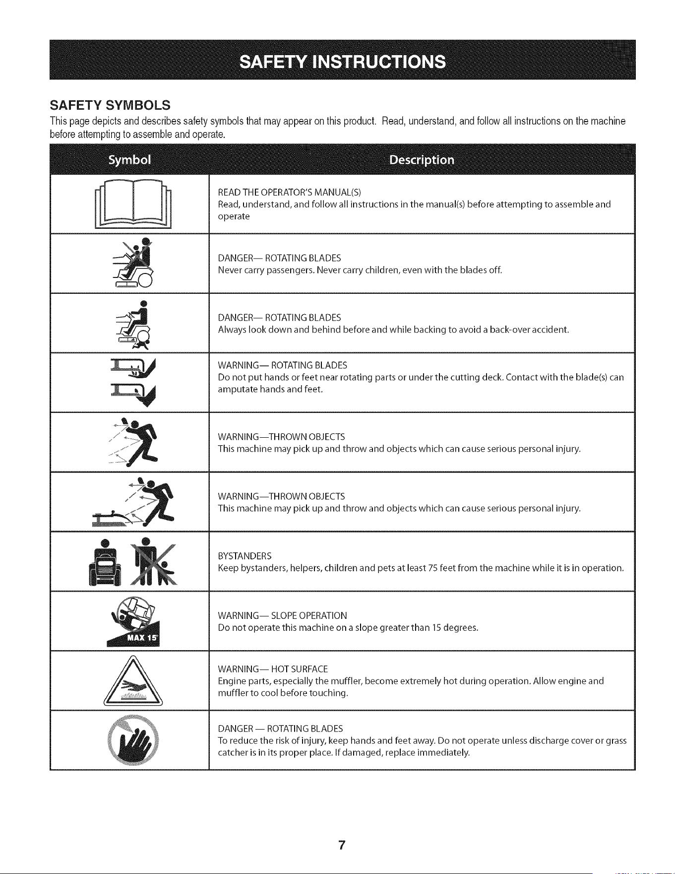
SAFETY SYMBOLS
Thispagedepictsand describessafety symbolsthatmay appearon this product. Read,understand,andfollowallinstructionson the machine
beforeattemptingto assembleandoperate.
0
A
READ THE OPERATOR'S MANUAL(S)
Read, understand, and follow all instructions in the manual(s) before attempting to assemble and
operate
DANGER-- ROTATING BLADES
Never carry passengers. Never carry children, even with the blades off.
DANGER-- ROTATING BLADES
Always look down and behind before and while backing to avoid a back-over accident.
WARNING-- ROTATING BLADES
Do not put hands or feet near rotating parts or under the cutting deck. Contact with the blade(s) can
amputate hands and feet.
WARNING--THROWN OBJECTS
This machine may pick up and throw and objects which can cause serious personal injury.
WARNING--THROWN OBJECTS
This machine may pick up and throw and objects which can cause serious personal injury.
BYSTANDERS
Keep bystanders, helpers, children and pets at least 75 feet from the machine while it is in operation.
WARNING-- SLOPE OPERATION
Do not operate this machine on a slope greater than 15 degrees.
WARNING-- HOT SURFACE
Engine parts, especially the muffler, become extremely hot during operation. Allow engine and
muffler to cool before touching.
DANGER-- ROTATING BLADES
To reduce the risk of injury, keep hands and feet away. Do not operate unless discharge cover or grass
catcher is in its proper place. If damaged, replace immediately.
7
(OK)
15° Slope
X
(TOO STEEP)
15° Slope
'_. _ Figure1
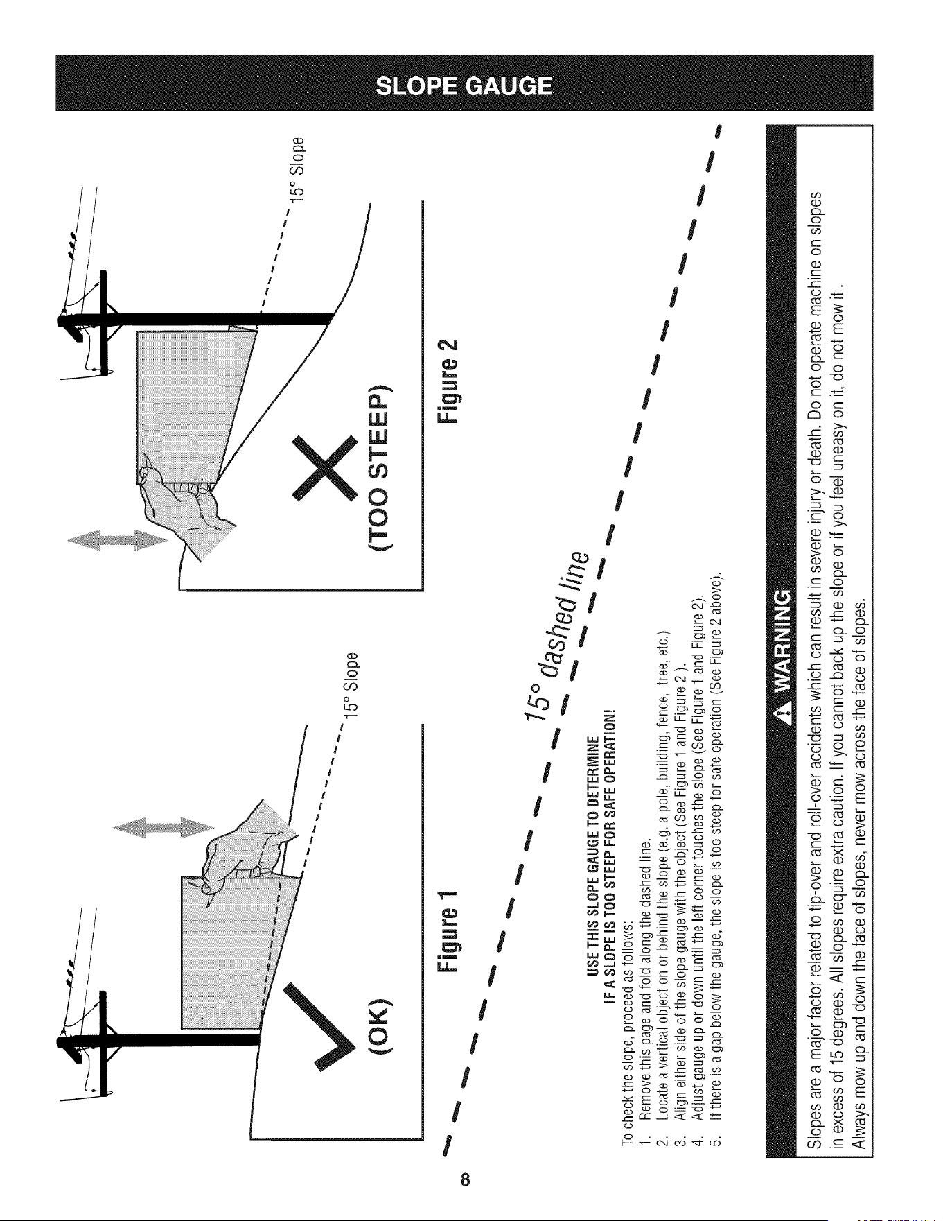
USETHISSLOPEGAUGETODETERMINE
IFA SLOPEIS TOOSTEEPFORSAFEOPERATION!
To checkthe slope,proceedas follows:
1. Removethis pageandfold along the dashedline.
2. Locatea verticalobject on or behindthe slope (e.g. a pole, building,fence, tree, etc.)
3. Align eitherside of the slope gaugewith the object(See Figure1 and Figure2 ).
4. Adjust gaugeupor down until the left cornertouchesthe slope (SeeFigure1and Figure2).
5.
15°
dashed line
If there is agap belowthe gauge,the slope is too steepfor safeoperation(SeeFigure2 above).
Figure2
Slopes are a majorfactor related to tip-over and roll-over accidents which can result in severe injury or death. Do not operatemachine on slopes
in excess of 15 degrees. All slopes require extra caution. If you cannot back up the slope or if you feel uneasy on it, do not mow it.
Always mow up and down the face of slopes, never mow across the face of slopes.
IM PORTANT: Yourtractorisshippedwithmotoroil intheengine.However,
youMUSTchecktheoillevelbeforeoperating.RefertotheService&Maintenance
sectionforinstructionsoncheckingtheoillevel.
NOTE:Any referencein this manualto the RIGHTor LEFTside of the
tractoris observedfrom operator'sseatpositionfacingforwardtowards
thefront of tractor.
Attaching the Battery Cables
CALIFORNIA PROPOSITION 65
Batteryposts,terminals,andrelatedaccessoriescontainleadand
leadcompounds,chemicalsknownto the Stateof Californiato
causecancerand reproductiveharm.Washhandsafterhandling.
Whenattaching battery cables,alwaysconnectthe POSITIVE([ted)wire to its
terminal first, followed bythe NEGATIVE(Black)wire.
Forshippingreasons,bothbatterycableson yourequipmenthavebeenleft
disconnectedfrom the terminalsat the factory.Toconnectthe batterycables,
proceedasfollows:
NOTE:ThepositivebatteryterminalismarkedPos.(+).Thenegativebattery
terminalismarkedNeg.(-).
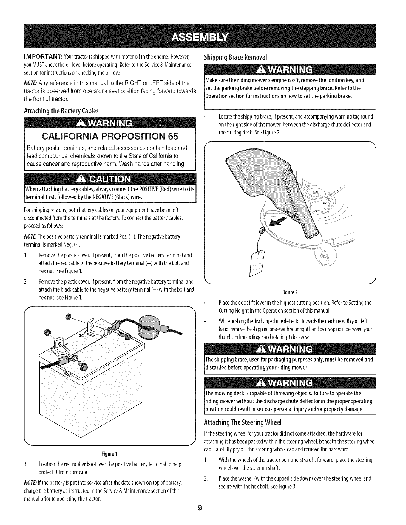
1. Removetheplasticcover,ifpresent,fromthepositivebatteryterminaland
attachtheredcableto the positivebatteryterminal(+) with the bolt and
hexnut.SeeFigure1.
2. Removetheplasticcover,ifpresent,fromthenegativebatteryterminaland
attachtheblackcableto thenegativebatteryterminal(-) with thebolt and
hexnut.SeeFigure1.
/
/
/
j-
/
/
/
/
/
f
./
/
/-
/
\ J
Figure1
3. Positionthe redrubberbootoverthe positivebatteryterminalto help
protectit fromcorrosion.
NOTE:Ifthe batteryisput intoserviceafter thedateshownon top of battery,
chargethe batteryasinstructedin the Service& Maintenancesectionofthis
manualpriorto operatingthetractor.
Shipping BraceRemoval
Makesurethe ridingmower'sengine isoff, removethe ignition key,and
set the parking brake beforeremovingthe shipping brace.Referto the
0perat on sect on for nstruct ons on howto setthe park ng brake.
Locatetheshippingbrace,if present,andaccompanyingwarningtag found
on therightsideof the mower,betweenthe dischargechutedeflectorand
thecuttingdeck.SeeFigure2.
Figure2
Placethedecklift leverin thehighestcutting position.Referto Settingthe
CuttingHeightinthe Operationsectionof thismanual.
Whilepushingthedischargechutedeflectortowardsthemachinewithyourleft
hand,removetheshippingbracewithyourrighthandbygraspingit betweenyour
thumbandindexfingerandrotatingit clockwise.
Theshipping brace,usedfor packagingpurposesonly, must beremovedand
discardedbefore operatingyour ridingmower.
Themowing deckiscapableof throwing objects. Failureto operate the
[riding mowerwithout the dischargechutedeflector inthe properoperating
[position could resultin seriouspersonalinjuryand/or property damage.
Attaching TheSteering Wheel
Ifthe steeringwheelforyourtractordid notcomeattached,the hardwarefor
attachingit hasbeenpackedwithin the steeringwheel,beneaththe steeringwheel
cap.Carefullypryoff the steeringwheelcapandremovethehardware.
I. Withthe wheelsof the tractorpointingstraightforward,placethesteering
wheeloverthesteeringshaft.
2. Placethewasher(with thecuppedsidedown)overthe steeringwheeland
securewith the hexbolt. SeeFigure3.
9
f
\
Figure3
3.
Placethesteeringwheelcapoverthecenterofthesteeringwheelandpush
downwarduntilit"clicks"intoplace.
Attaching TheSeat
NOTE: Forshippingreasons,the seatiseitherfastenedto thetractor
seat'spivotbracketwitha plastictie, or mountedbackwardto the pivot
bracket.Ineithercase,free the seatfromitsshippingpositionbeing
carefulnotto bendor kink the wiringharnessandfollowtheinstruc-
tionsbelowto attach it.
1. Removethetwohexscrewsandnutsfromtheseatpivotbracket.
2. Alignthefrontholesoftheseatmountingbracketwiththeholesintheseat
pivotbracketonyourtractorandsecurewithpreviouslyremovedhexscrews
andnuts.SeeAinFigure4.
3. Plugthewiringharnessintotheseatsafetyswitchinthebottomoftheseat,
asshowninBof Figure4.
flOTE:Thetractorwillnotoperatewiththewiringharnessdisconnected.
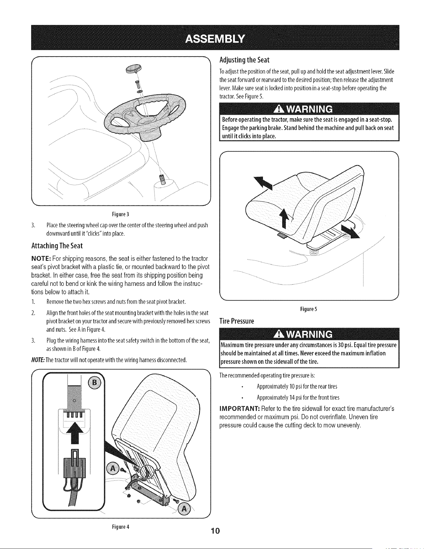
Adjusting the Seat
Toadjustthepositionof theseat,pull upandholdtheseatadjustmentlever.Slide
theseatforwardor rearwardto thedesiredposition;thenreleasetheadjustment
lever.Makesureseatislockedinto positioninaseat-stopbeforeoperatingthe
tractor.SeeFigure5.
Beforeoperatingthe tractor, makesurethe seat isengagedin a seat-stop.
Engagethe parkingbrake.Standbehindthe machineand pull backon seat
until it clicksintoplace.
_,, ,J
Figure5
Tire Pressure
Maximum tire pressureunderany circumstancesis30 psi.Equaltire pressure
shouldbe maintained at all times. Neverexceedthe maximum inflation
)ressureshown on the sidewallof the tire.
Therecommendedoperatingtirepressureis:
Approximately10psiforthereartires
Approximately14psiforthefronttires
IMPORTANT: Referto the tire sidewallfor exacttire manufacturer's
recommendedormaximumpsi.Donot overinflate.Uneventire
pressurecouldcausethe cuttingdeckto mowunevenly.
Figure4
10
.I
G
A
©
H
f
B
D
E
F
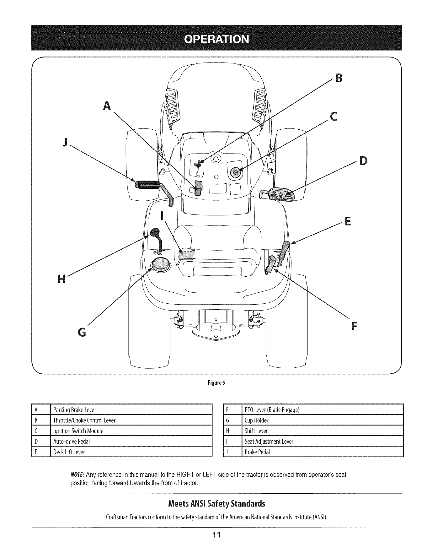
Figure6
A ParkingBrakeLever
B ThrotNe/ChokeControlLever
C IgnitionSwitchModule
D Auto-drivePedal
E DeckLift Lever
F PTOLever(BladeEngage)
G CupHolder
H ShiftLever
I SeatAdjustmentLever
J BrakePedal
flOTE:Any referenceinthismanualto the RIGHTor LEFTside of the tractoris observedfromoperator'sseat
positionfacingforwardtowardsthe frontof tractor.
MeetsANSiSafetyStandards
CraftsmanTractorsconformto the safetystandardoftheAmericanNationalStandardsInstitute(ANSI).
11
ParkingBrakeLever
Tosetthe parkingbrake:Fullydepressthe brakepedal.Movethe
parkingbrakeleverintotheparkingbrakeposition.Releasethe
brakepedalto allowtheparkingbraketo engage.
Toreleasetheparkingbrake:Depressthebrakepedalandthe
parkingbrakeleverwill moveoutof theparkingbrakepositionon
itsown.Theparkingbrakewill thenbe released.Releasethebrake
pedal.
NOTE:Theparkingbrakemustbesetif theoperatorleavesthe seat
with the enginerunningortheenginewill automaticallyshutoff.
Throttle/chokeControlLever
m
m
mlmmmml
mmmmmmm
SLOW
Thethrottle/chokecontrolleverislocatedonthe
left sideof the tractor'sdashpanel.Thislever
controlsthespeedof theengineandwhenpushed
all thewayforward,the chokecontrolalso.When
setinagivenposition,thethrottle will maintaina
uniformenginespeed.
IMPOR@N#Whenoperating the tractor with the cutting
deck engaged, the throttle/choke control lever must
always be in the FAST (rabbit) position.
ignitionSwitch
Thekeyswitchmoduleisusedtostart andstoptheengine.Insert
keyintothekeyswitchmoduleandturn clockwiseto the START
position.Releasethe keyintothe normalmowingpositiononce
enginehasstarted.Theheadlightswill beactivatedautomatkally.
Tostoptheengine,turn theignitionkeycounterclockwiseto the
STOPposition.
IMPORTANT:Priorto operatingthe
tractor,referto boththe "Safety
InterlockSystem"and"StartingThe
Engine"laterinthissectionof this
manualfordetailedinstructions
regardingthe IgnitionSwitch
Module.
Neverleavearunning machineunattended.AlwaysdisengagePTO(Blade
EngageLever),moveshift leverintoneutralposition, set parkingbrake,
stopengineand removekeyto prevent unintendedstarting.
Seat Adjustment Lever
Theseatadjustmentleverislocatedbelowthefront/left of theseat.Thelever
allowsforadjustmentof theforeandaft positionof the seat.Referto theAssembly
sectionof the manualformoredetailedinstructionsforadjustingthe seatposition.
Auto-drivepedal
Thedrivepedalis locatedontheright sideof the tractor,alongtherunningboard.
Depressthedrivepedalforwardandthetractorwill moveinthedirectionthatthe
shift leverisengagedin.Tocausethe tractorto travelforward,whileata complete
stop,movethe shift leverinto theForwardposition.Graduallysteponthedrive
pedalandthetractorwill beginto moveforward.TomoveinReverse,follow the
sameprocedureonlymovetheshift leverintothereverseposition.
Thegroundspeediscontrolledwith thedrivepedal.Thefurther forwardthat the
pedalis pivoted,thefasterthetractorwill travel.Thepedalwill returnto its original
positionwhenit'snotdepressed.Referto theOperationsectionofthis manualfor
detailedinstructionsregardingthedrivepedal.
IMPOR@NT_Always set the parking brake when leaving the tractor
unattended.
DeckLift Lever
Foundon yourtractor'srightfender,thedecklift leverisusedto
changetheheightof the cuttingdeck.Touse,movethelevertothe
left, thenplaceinthenotchbestsuitedforyourapplication.
PTO(Blade Engage)Lever
Foundon thetractor'srightfender,the PTO(bladeengage)lever
isusedto engagepowerto thecuttingdeckorother(separately
available)attachments.Tooperate,movethe leverallthe way
forward.Movingthe leverallthe wayrearwardintothe PTOOFF
positiondisengagespowerto thecutting deck/attachment.
NOTE:ThePTO (blade engage) lever must be in the
disengaged (PTO OFF) position when starting the engine.
CupHolder
Thetractor'scupholderislocatedonthe fenderto the left of the seat.
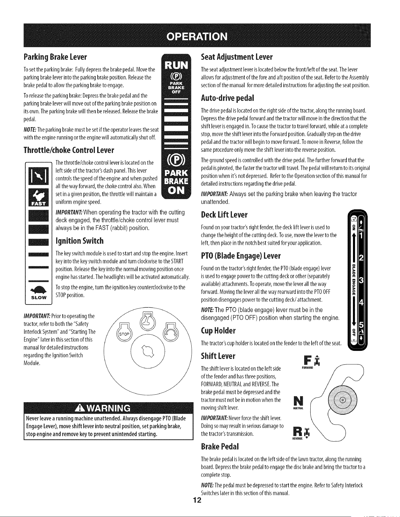
Shift Lover
Theshift leverislocatedon theleft side
of thefenderandhasthreepositions,
FORWARD,NEUTRALandREVERSE.The
brakepedalmustbedepressedandthe
tractormustnotbeinmotionwhenthe
movingshift lever.
IMPORTAN_Neverforcethe shift lever.
Doingsomayresultinseriousdamageto
thetractor'stransmission.
BrakePedal
REVERSE
Thebrakepedalis locatedontheleft sideofthelawntractor,alongtherunning
board.Depressthebrakepedalto engagethediscbrakeandbringthetractorto a
completestop.
NOTE:Thepedalmustbedepressedtostart theengine.Referto SafetyInterlock
Switcheslaterin thissectionof thismanual.
12
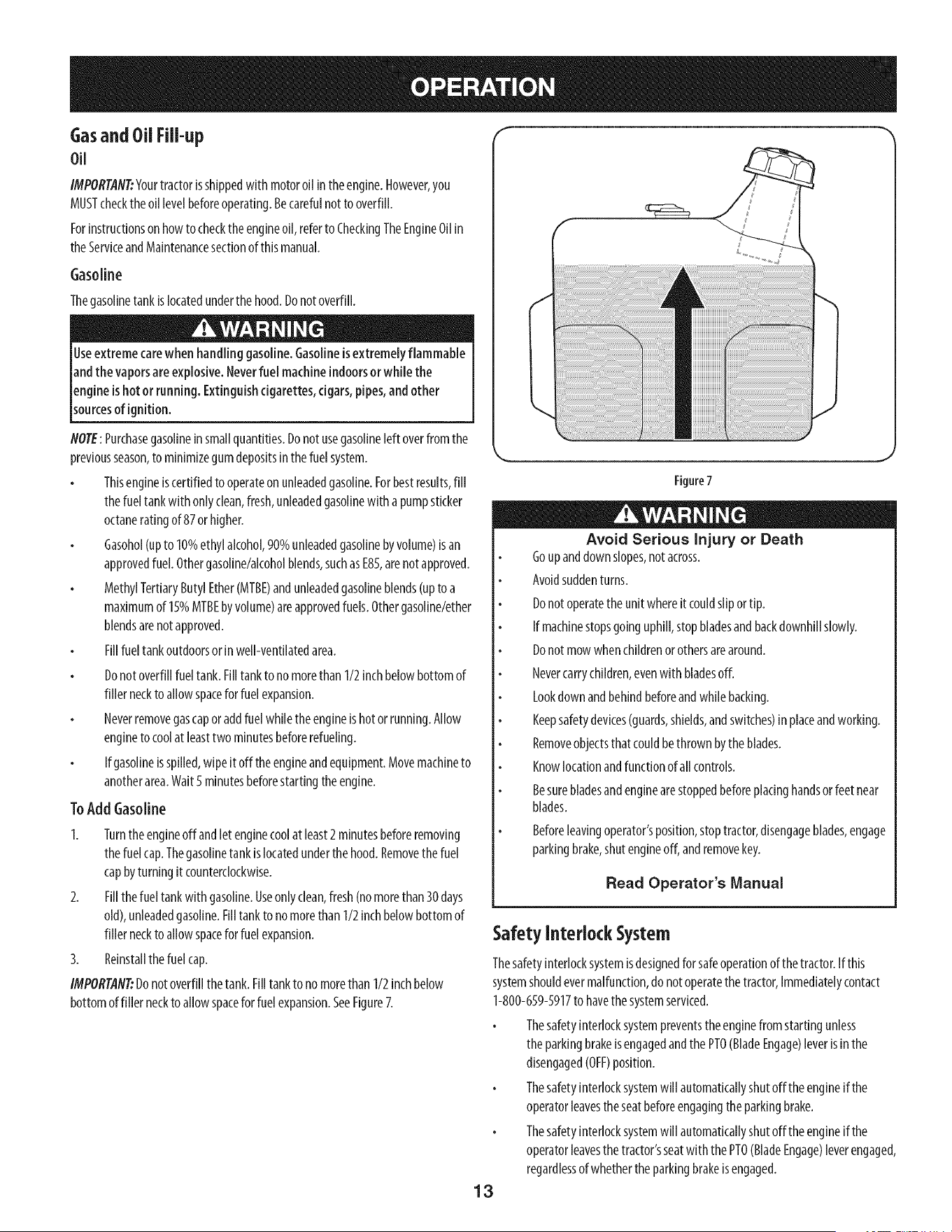
Gasand Oil Fill-up
Oil
IMPORTAfl#Yourtractorisshippedwith motoroil intheengine.However,you
MUSTchecktheoil levelbeforeoperating.Becarefulnottooverfill.
Forinstructionsonhowto checkthe engineoil,referto CheckingTheEngineOilin
theServiceandMaintenancesectionof thismanual.
Gasoline
Thegasolinetankislocatedunderthehood.Donotoverfill.
Useextreme carewhen handling gasoline.Gasolineisextremely flammable
andthe vaporsareexplosive.Neverfuel machineindoorsorwhile the
engineishotor running. Extinguishcigarettes,cigars,pipes,andother
sourcesof gn t on.
NOTE:Purchasegasolineinsmallquantities.Donotusegasolineleft overfromthe
previousseason,to minimizegumdepositsinthefuel system.
Thisengineiscertifiedto operateon unleadedgasoline.Forbestresults,fill
thefueltank with onlyclean,fresh,unleadedgasolinewith apumpsticker
octaneratingof 87or higher.
Gasohol(upto 10%ethyl alcohol,90%unleadedgasolinebyvolume)isan
approvedfuel. Othergasoline/alcoholblends,suchasE85,arenotapproved.
MethylTertiaryButylEther(MTBE)andunleadedgasolineblends(upto a
maximumof 15%MTBEbyvolume)areapprovedfuels.Othergasoline/ether
blendsarenotapproved.
Fillfueltank outdoorsor inwell-ventilatedarea.
Donotoverfillfueltank.Filltankto nomorethan1/2inchbelowbottomof
filler neckto allowspaceforfuel expansion.
Neverremovegascapor addfuelwhiletheengineis hotor running.Allow
engineto coolat leasttwo minutesbeforerefueling.
If gasolineisspilled,wipeit off theengineandequipment.Movemachineto
anotherarea.Wait5 minutesbeforestartingtheengine.
ToAdd Gasoline
1. Turnthe engineoff andletenginecoolat least2minutesbeforeremoving
thefuelcap.Thegasolinetank islocatedunderthehood.Removethefuel
capbyturningit counterclockwise.
2. Fillthefuel tankwith gasoline.Useonlyclean,fresh(nomorethan30days
old),unleadedgasoline.Filltankto nomorethan1/2inchbelowbottomof
filler neckto allowspaceforfuel expansion.
3. Reinstallthefuel cap.
IMPORTAN_Donotoverfillthetank.Filltankto no morethan 1/2inchbelow
bottomoffiller neckto allowspaceforfuel expansion.SeeFigure7.
Figure7
Avoid Serious Injury or Death
Goupanddownslopes,notacross.
Avoidsuddenturns.
Donotoperatetheunitwhereit couldslipor tip.
If machinestopsgoinguphill,stopbladesandbackdownhillslowly.
Donotmowwhenchildrenorothersarearound.
Nevercarrychildren,evenwith bladesoff.
Lookdown andbehindbeforeandwhilebacking.
Keepsafetydevices(guards,shields,andswitches)inplaceandworking.
Removeobjectsthat couldbethrown bytheblades.
Knowlocationandfunctionof all controls.
Besurebladesandenginearestoppedbeforeplacinghandsorfeet near
blades.
Beforeleavingoperator'sposition,stoptractor,disengageblades,engage
parkingbrake,shutengineoff, andremovekey.
Read Operator's Manual
Safety Interlock System
Thesafetyinterlocksystemisdesignedfor safeoperationofthetractor.Ifthis
systemshouldevermalfunction,do not operatethe tractor,Immediatelycontact
1-800-659-5917to havethe systemserviced.
Thesafetyinterlocksystempreventstheenginefrom startingunless
theparkingbrakeisengagedandthePTO(BladeEngage)leverisinthe
disengaged(OFF)position.
Thesafetyinterlocksystemwill automaticallyshutoff the engineifthe
operatorleavestheseatbeforeengagingtheparkingbrake.
Thesafetyinterlocksystemwill automaticallyshutoff the engineifthe
operatorleavesthetractor'sseatwiththe PTO(BladeEngage)leverengaged,
regardlessofwhethertheparkingbrakeisengaged.
13
Theenginewill automaticallyshut off if thePTO(BladeEngage)leveris
movedintotheengaged(ON)positionwith theshift leverinReverse.
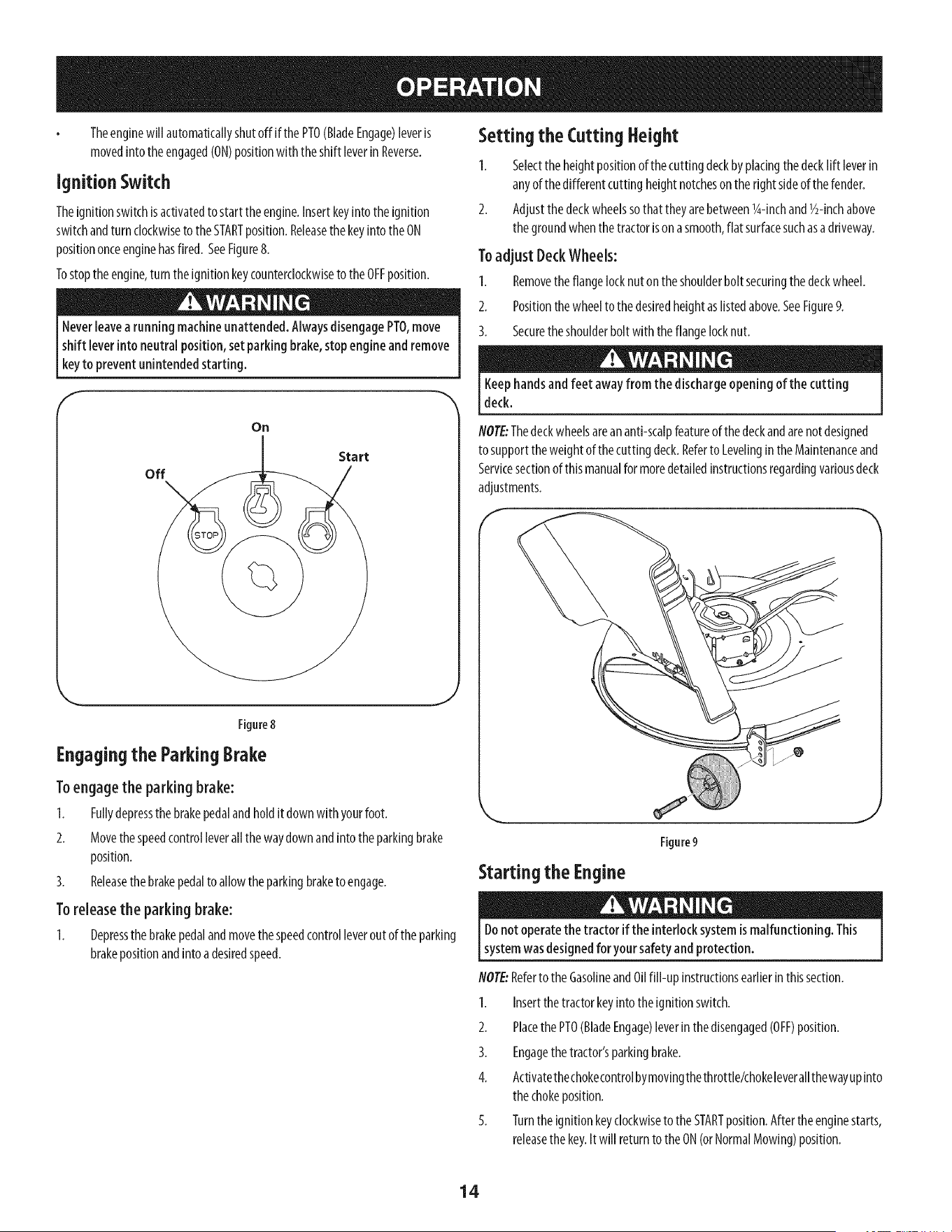
Ignition Switch
Theignitionswitchisactivatedto startthe engine.Insertkeyintothe ignition
switchandturn clockwiseto theSTARTposition.ReleasethekeyintotheON
positiononceenginehasfired. SeeFigure8.
Tostoptheengine,turn theignitionkeycounterclockwiseto the OFFposition.
Neverleavearunning machineunattended.AlwaysdisengagePTO,move
shift leverintoneutral position, set parkingbrake,stopengineand remove
keyto prevent unintendedstarting.
f
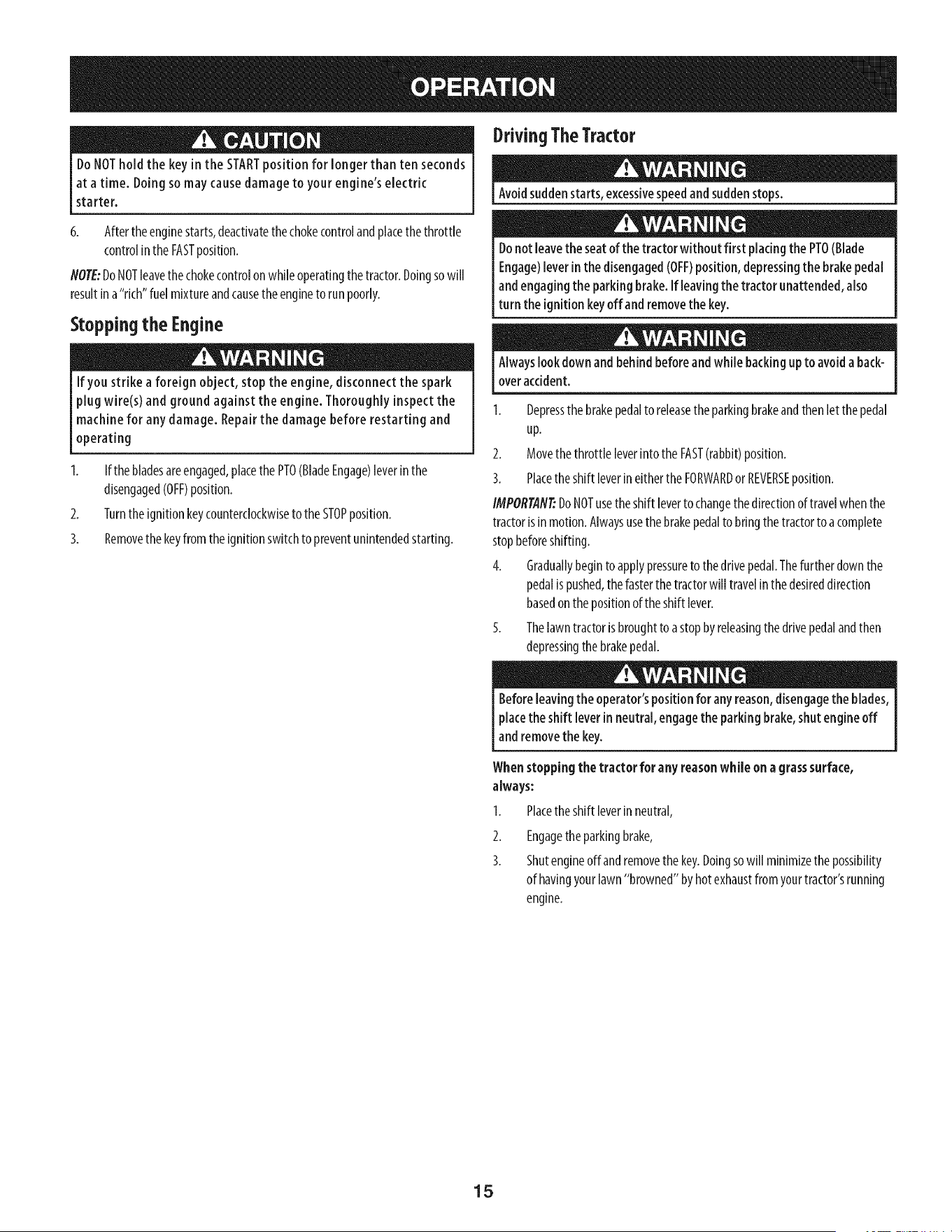
Setting the Cutting Height
1. Selectthe heightpositionof thecuttingdeckbyplacingthe decklift leverin
anyof thedifferentcutting heightnotcheson the rightsideof thefender.
2. Adjustthe deckwheelssothatthey arebetweenl_-inchand1/2-inchabove
thegroundwhenthetractorison asmooth,flat surfacesuchasadriveway.
To adjust Deck Wheels:
1. Removetheflangelocknuton theshoulderbolt securingthedeckwheel.
2. Positionthe wheelto thedesiredheightaslistedabove.SeeFigure9.
3. Securetheshoulderbolt with the flangelocknut.
Keephandsandfeet away from the dischargeopening of the cutting
deck.
off
On
Start
Figure8
Engagingthe ParkingBrake
Toengagethe parking brake:
1. Fullydepressthe brakepedalandholdit downwith yourfoot.
2. Movethespeedcontrolleverall the waydownandintotheparkingbrake
position.
3. Releasethe brakepedalto allowtheparkingbraketo engage.
Toreleasethe parking brake:
1. Depressthebrakepedalandmovethespeedcontrolleverout of theparking
brakepositionandinto adesiredspeed.
NOTE:Thedeckwheelsareananti-scalpfeatureof thedeckandarenotdesigned
to supportthe weightof thecuttingdeck.Referto LevelingintheMaintenanceand
Servicesectionof thismanualformoredetailedinstructionsregardingvariousdeck
adjustments.
Starting the Engine
Figure9
J
Donotoperatethe tractor if the interlocksystemismalfunctioning. This
systemwasdesignedfor your safetyandprotection.
NOTE:Referto the GasolineandOilfill-up instructionsearlierinthissection.
1. Insertthe tractorkeyintotheignitionswitch.
2. PlacethePTO(BladeEngage)leverinthedisengaged(OFF)position.
3. Engagethetractor'sparkingbrake.
4. Activatethechokecontrolbymovingthethrottle/chokeleverallthewayupinto
thechokeposition.
5. Turnthe ignitionkeyclockwiseto theSTARTposition.Aftertheenginestarts,
releasethekey.It will returnto theON(orNormalMowing)position.
14
DoNOThold the key in the STARTposition for longerthan ten seconds
at a time. Doingso may causedamageto your engine's electric
starter.
6. Afterthe enginestarts,deactivatethechokecontrolandplacethe throttle
controlin theFASTposition.
NOTE:DoNOTleavethe chokecontrolon whileoperatingthetractor.Doingsowill
resultin a"rich"fuel mixtureandcausetheengineto runpoorly.
Stopping the Engine
If you strike a foreign object, stop the engine, disconnect the spark
plug wire(s) and ground against the engine. Thoroughly inspect the
machine for any damage. Repair the damage before restarting and
operating
2.
3.
If the bladesareengaged,placethe PTO(BladeEngage)leverinthe
disengaged(OFF)position.
Turnthe ignitionkeycounterclockwiseto theSTOPposition.
Removethe keyfrom the ignitionswitchto preventunintendedstarting.
DrivingTheTractor
Avoidsuddenstarts,excessivespeedandsuddenstops.
Donot leavethe seatofthe tractor without first placingthe PTO(Blade
Engage)leverinthe disengaged(OFF)position, depressingthe brakepedal
andengaging the parkingbrake. If leavingthe tractor unattended,also
turn the ignitionkeyoffand removethe key.
Alwayslook down and behind beforeandwhile backingupto avoid a back-
overaccident.
1. Depressthe brakepedalto releasetheparkingbrakeandthenlet the pedal
up.
2. Movethe throttle leverinto theFAST(rabbit)position.
3. Placetheshift leverineithertheFORWARDor REVERSEposition.
IMPORTAN_DoNOTusetheshift leverto changethe directionof travelwhenthe
tractorisin motion.Alwaysusethebrakepedalto bringthe tractorto acomplete
stopbeforeshifting.
4. Graduallybeginto applypressureto the drivepedal.Thefurther downthe
pedalis pushed,thefasterthetractorwill travelinthe desireddirection
basedon thepositionof the shift lever.
5. Thelawntractorisbroughtto astopbyreleasingthe drivepedalandthen
depressingthe brakepedal.
Beforeleavingthe operator'spositionfor any reason,disengagethe blades,
placethe shift leverin neutral,engagethe parking brake,shutengineoff
and removethe key.
Whenstoppingthe tractor for anyreasonwhile ona grasssurface,
always:
Placetheshift leverinneutral,
I.
2.
3.
Engagetheparkingbrake,
Shutengineoffand removethekey.Doingsowill minimizethepossibility
of havingyourlawn"browned"byhot exhaustfromyourtractor'srunning
engine.
15
DrivingOnSlopes
Referto theSLOPEGAUGEinthe SafetyInstructionssectionofthe manualto help
determineslopeswhereyoumayoperatethistractorsafely.
Donot mowon inclineswith a slopeinexcessof 15 degrees(a riseof
approximately2-1/2feet every 10feet).Thetractor could overturn and
causeseriousinjury.
Mowupanddownslopes,NEVERacross.
Exerciseextremecautionwhenchangingdirectiononslopes.
Watchfor holes,ruts,bumps,rocks,or otherhiddenobjects.Uneventerrain
couldoverturnthe machine.Tallgrasscanhideobstacles.
Avoidturnswhendrivingon aslope.Ira turn mustbemade,turn downthe
slope.Turningup aslopegreatlyincreasesthechanceof aroll over.
Avoidstoppingwhendrivingupaslope.If it isnecessaryto stopwhile
drivingupaslope,startup smoothlyandcarefullyto reducethe possibility
of flippingthe tractoroverbackward.
Engaging the Blades
Engagingthe PTO(BladeEngage)transferspowertothecuttingdeckorother
(separatelyavailable)attachments.Toengagetheblades,proceedasfollows:
1. Movethethrottle/chokecontrolleverto the FAST(rabbit)position.
2. GraspthePTO(BladeEngage)leverandpivotit allthe wayforwardintothe
engaged(ON)position.
3. Keepthethrottleleverinthe FAST(rabbit)positionfor themostefficientuse
of thecutting deckor other(separatelyavailable)attachments.
NOTE:Theenginewill automaticallyshutoff ifthe PTOisengagedwith theshift
leverinpositionforreversetravelwith theignitionkeyin theONposition.
Mulching
Amulchkit isavailableasanattachment.Mulchingisa processof recirculating
grassclippingsrepeatedlybeneaththecuttingdeck.Theultra-fineclippingsare
thenforcedbackintothe lawnwherethey actasanaturalfertilizer.
Amulchkit canbepurchasedthroughtheretaillocationinwhichyoupurchased
thistractor.Formoreinformation,simplycontactSearsat 1-800-659-5917.
Mowing
Tohelpavoid bladecontactor athrown object injury,keepbystanders,
helpers,childrenandpetsat least75feet from the machinewhile it isin
operation.Stopmachineif anyoneentersthe area.
Thefollowinginformationwill behelpfulwhenusingthecuttingdeckwith your
tractor:
Planyour mowing patternto avoid dischargeof materialstowardroads,
sidewalks,bystandersandthe like.Also,avoiddischargingmaterial against
awall or obstructionwhich maycausedischargedmaterial to ricochetback
toward the operator.
Donotmowat highgroundspeed,especiallyira mulchkit or grasscollector
isinstalled.
Forbestresultsit isrecommendedthatthefirst two lapsbe cutwith the
dischargethrowntowardsthecenter.Afterthe first two laps,reversethe
directionto throwthe dischargeto theoutsideforthebalanceof cutting.
Thiswill giveabetterappearanceto the lawn.
Donotcutthegrasstoo short.Shortgrassinvitesweedgrowthandyellows
quicklyindryweather.
Mowingshouldalwaysbedonewith theengineatfull throttle.
Underheavierconditionsit maybenecessaryto gobackoverthecutareaa
secondtimeto get acleancut.
DoNOTattemptto mowheavybrushandweedsandextremelytall grass.
Yourtractorisdesignedto mowlawns,NOTclearbrush.
Keepthebladessharpandreplacethe bladeswhenworn.Referto Cutting
Bladesin the Servicesectionof thismanualforproperbladesharpening
instructions.
Headlights
ThelampsareONwheneverthetractor'sengineisrunning.
Thelampsturn OFFwhentheignitionkeyis movedto the STOPposition.
Using the Deck Lift Lever
Toraisethe cuttingdeck,movethedecklift leverto the left,then placeit inthe
notchbestsuitedfor yourapplication.Referto SettingTheCuttingHeightearlierin
thissection.
16
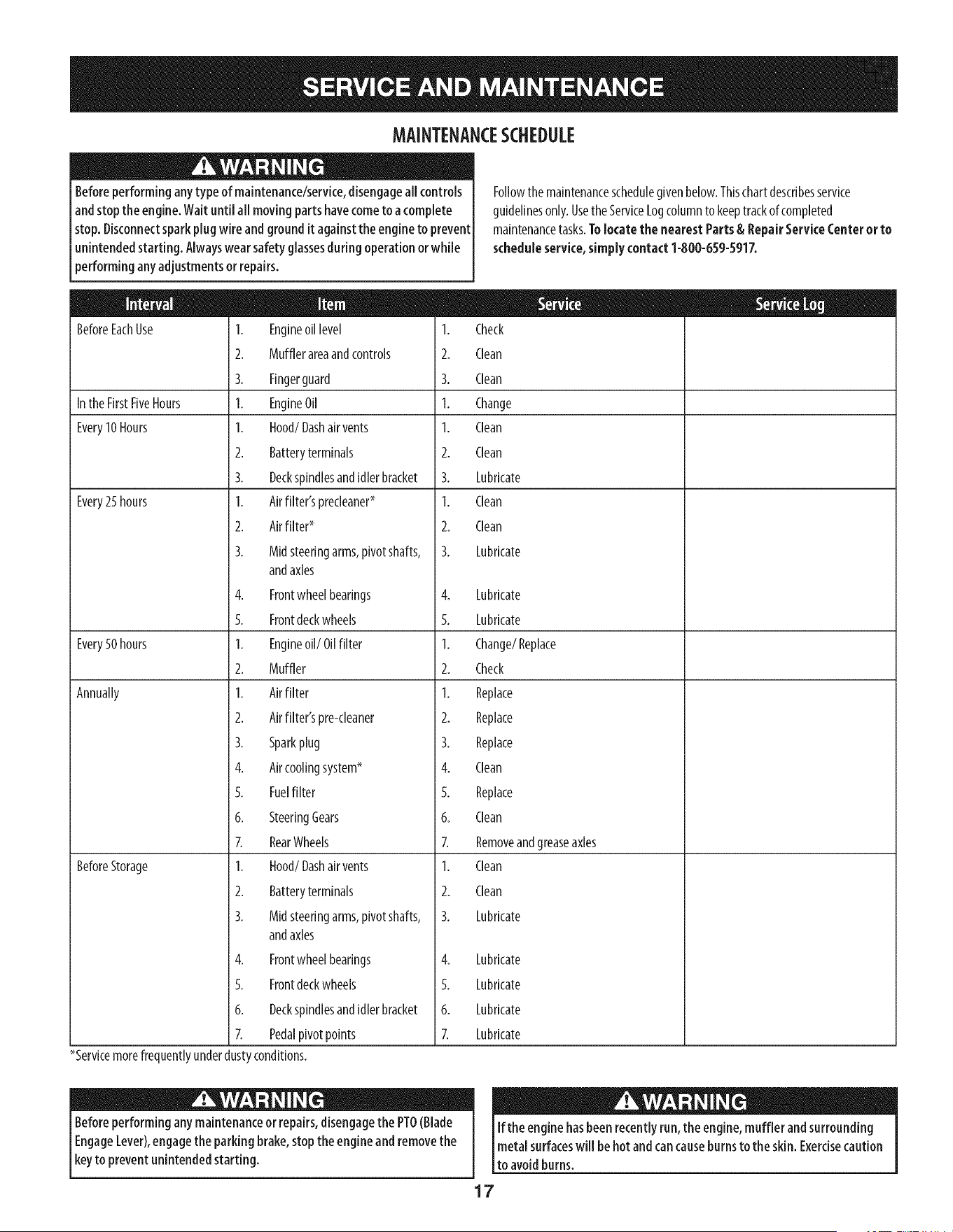
MAINTENANCESCHEDULE
Beforeperforming anytype of maintenance/service,disengageall controls
andstopthe engine.Waituntil all moving parts havecometo a complete
stop.Disconnectsparkplugwire andground it againstthe engineto prevent
unintendedstarting. Alwayswearsafety glassesduring operationorwhile
performing anyadjustments or repairs.
BeforeEachUse 1. Engineoil level 1.
2. Mufflerareaandcontrols 2.
3. Fingerguard 3.
Inthe FirstFiveHours 1. EngineOil 1.
Every10Hours I. Hood/Dashair vents I.
2. Batteryterminals 2.
3. Deckspindlesandidlerbracket 3.
Every25 hours 1. Airfilter'sprecleaner* 1.
2. Airfilter* 2.
3. Midsteeringarms,pivotshafts, 3.
andaxles
4. Frontwheelbearings 4.
5. Frontdeckwheels 5.
Every50 hours 1. Engineoil/Oil filter 1.
2. Muffler 2.
Annually 1. Airfilter 1.
2. Airfilter'spre-cleaner 2.
3. Sparkplug 3.
4. Aircoolingsystem* 4.
5. Fuelfilter 5.
6. SteeringGears 6.
7. RearWheels 7.
BeforeStorage 1. Hood/Dashair vents 1.
2. Batteryterminals 2.
3. Midsteeringarms,pivotshafts, 3.
andaxles
4. Frontwheelbearings
5. Frontdeckwheels
6. Deckspindlesandidlerbracket
7. Pedalpivotpoints
*Servicemorefrequentlyunderdustyconditions.
Followthe maintenanceschedulegivenbelow.Thischartdescribesservice
guidelinesonly.Usethe ServiceLogcolumnto keeptrackofcompleted
maintenancetasks.Tolocate the nearest Parts & RepairServiceCenter or to
scheduleservice, simply contact1-800-659-5917.
Check
Clean
Clean
Change
Clean
Clean
Lubricate
Clean
Clean
Lubricate
Lubricate
Lubricate
Change/Replace
Check
Replace
Replace
Replace
Clean
Replace
Clean
Removeandgreaseaxles
Clean
Clean
Lubricate
4. Lubricate
5. Lubricate
6. Lubricate
7. Lubricate
Beforeperformingany maintenanceor repairs,disengagethe PTO(Blade
EngageLever),engagethe parking brake,stopthe engine andremovethe
keyto prevent unintendedstarting.
If the enginehasbeen recentlyrun, the engine,muffler andsurrounding
metal surfaceswill behot andcancauseburnsto the skin. Exercisecaution
to avoidburns.
17
Engine Maintenance
Checkingthe EngineOil
Onlyusehighqualitydetergentoil ratedwith APIserviceclassificationSF,SG,
SH,or SJ.Selecttheoil'sSAEviscositygradeaccordingto theexpectedoperating
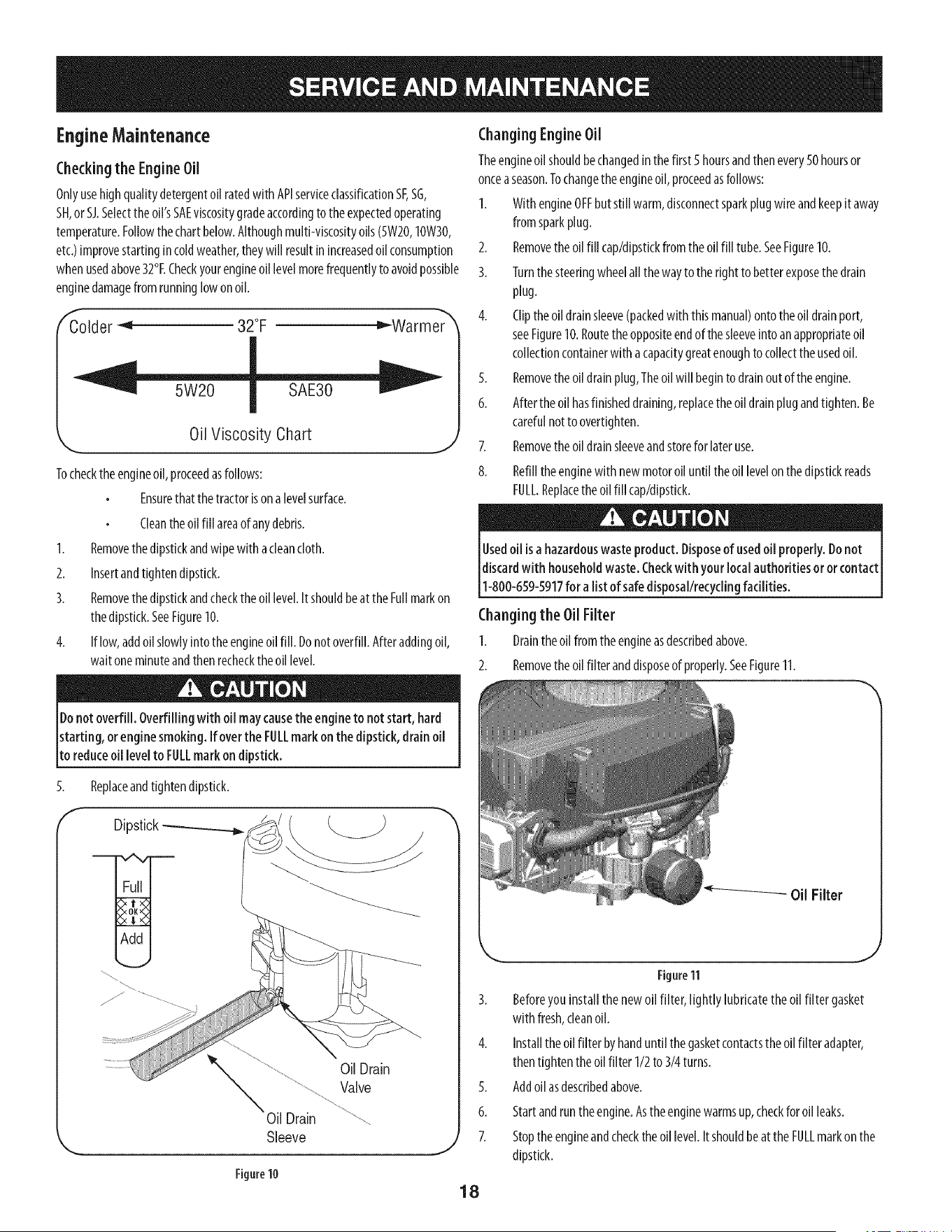
temperature.Followthechartbelow.Althoughmulti-viscosityoils(5W20,10W30,
etc.)improvestartingin coldweather,theywill resultinincreasedoil consumption
whenusedabove32°I.Checkyourengineoil levelmorefrequentlyto avoidpossible
enginedamagefrom runninglowon oil.
f
Colder _'_ 32°F _Warmer
Oil Viscosity Chart
Tochecktheengineoil,proceedasfollows:
Ensurethatthetractorison alevelsurface.
J
Cleanthe oil fill areaof anydebris.
1. Removethedipstickandwipewith acleancloth.
2. Insertandtightendipstick.
3. Removethedipstickandcheckthe oil level.Itshouldbeat theFullmarkon
thedipstick.SeeFigure10.
4. If low,addoil slowlyinto the engineoil fill. Donotoverfill.Afteraddingoil,
waitoneminuteandthenrecheckthe oil level.
Donotoverfill. Overfilling with oil maycausethe engine to not start, hard
starting, or engine smoking. If overthe FULLmark on the dipstick, drain oil
to reduceoil levelto FULLmark on dipstick.
ChangingEngineOil
Theengineoil shouldbechangedin thefirst 5hoursandthenevery50 hoursor
onceaseason.Tochangethe engineoil, proceedasfollows:
I. With engineOFFbutstill warm,disconnectsparkplugwire andkeepitaway
from sparkplug.
2. Removethe oil fill cap/dipstkkfromthe oil fill tube.SeeFigure10.
3. Turnthe steeringwheelall thewayto the rightto betterexposethedrain
plug.
4. Clipthe oil drainsleeve(packedwith thismanual)ontotheoil drainport,
seeFigure10.Routethe oppositeendof thesleeveinto anappropriateoil
collectioncontainerwith acapacitygreatenoughto collecttheusedoil.
5. Removethe oil drainplug,Theoilwill beginto drainoutof the engine.
6. Afterthe oil hasfinisheddraining,replacetheoil drainplugandtighten.Be
carefulnotto overtighten.
7. Removethe oil drainsleeveandstoreforlateruse.
8. Refilltheenginewith newmotoroil untiltheoil levelonthe dipstickreads
FULL.Replacetheoil fill cap/dipstkk.
Usedoil is a hazardouswaste product. Disposeof usedoil properly. Donot
discardwith householdwaste.Checkwith your localauthoritiesor or contact
1-800-659-5917for a list of safedisposal/recyclingfacilities.
Changingthe Oil Filter
I. Draintheoilfromtheengineasdescribedabove.
2. Removetheoilfilteranddisposeofproperly.SeeFigure11.
5.
f
Replaceandtightendipstick.
Dipstick
OilDrain
Valve
Oil Drain
Sleeve
Figure10
J
18
Figure11
3. Beforeyou installthenewoil filter, lightly lubricatetheoil filter gasket
with fresh,cleanoil.
4. Installthe oil filter byhanduntil thegasketcontactsthe oil filter adapter,
thentighten theoil filter 1/2to 3/4turns.
5. Addoilasdescribedabove.
6. Startandruntheengine.Astheenginewarmsup,checkforoil leaks.
7. Stoptheengineandchecktheoillevel.Itshouldbeat theFULLmarkon the
dipstick.
FuelFilter
Gasolineanditsvaporsare e×tremelyflammable andexplosive.Fireor
explosioncan causesevereburns ordeath.
Keepgasolineawayfromsparks,openflames,pilot lights,heat,andother
ignitionsources.
Checkfuellines,tank,cap,andfittingsfrequentlyforcracksor leaks.Replace
if necessary.
Beforereplacingthe fuelfilter, drainthe fuel tank aspertheinstructions
below.
Donotdrainfuel whentheengineishot.Allowtheengineadequatetime to
cool.Drainfuel into anapprovedcontaineroutdoors,awayfromopenflame.
Drainanylargevolumeoffuel from thetankbydisconnectingthefuel line
fromthe in-linefuelfilter neartheengine.
Removethe fuel linefromthe In-lineside(sidetowardsthe fuel tank)of the
fuelfilter.
Replacementpartsmustbethesameandinstalledinthe samepositionas
theoriginalparts.
If fuelspills,wait until it evaporatesbeforestartingengine.
Beforereplacingthe fuelfilter, drainthe fuel tank.Otherwise,fuelcanleak
outandcauseafireorexplosion.
To Drain the fuel:
1. Locatethefuel filter,whichisroutedontheleft sideof theenginebetween
thefueltankandthecarburetor,andmaybeattachedtotheenginewith atie
strap.Cutthetie strap,if present,thenpinchthe in-lineclamponthefuel filter
withapairof pliers,slidetheclampupthefuelline.Pullthefuel linefreefrom
thefilterandplacetheopenendof the lineintoanapprovedcontainerto drain
thefuel.
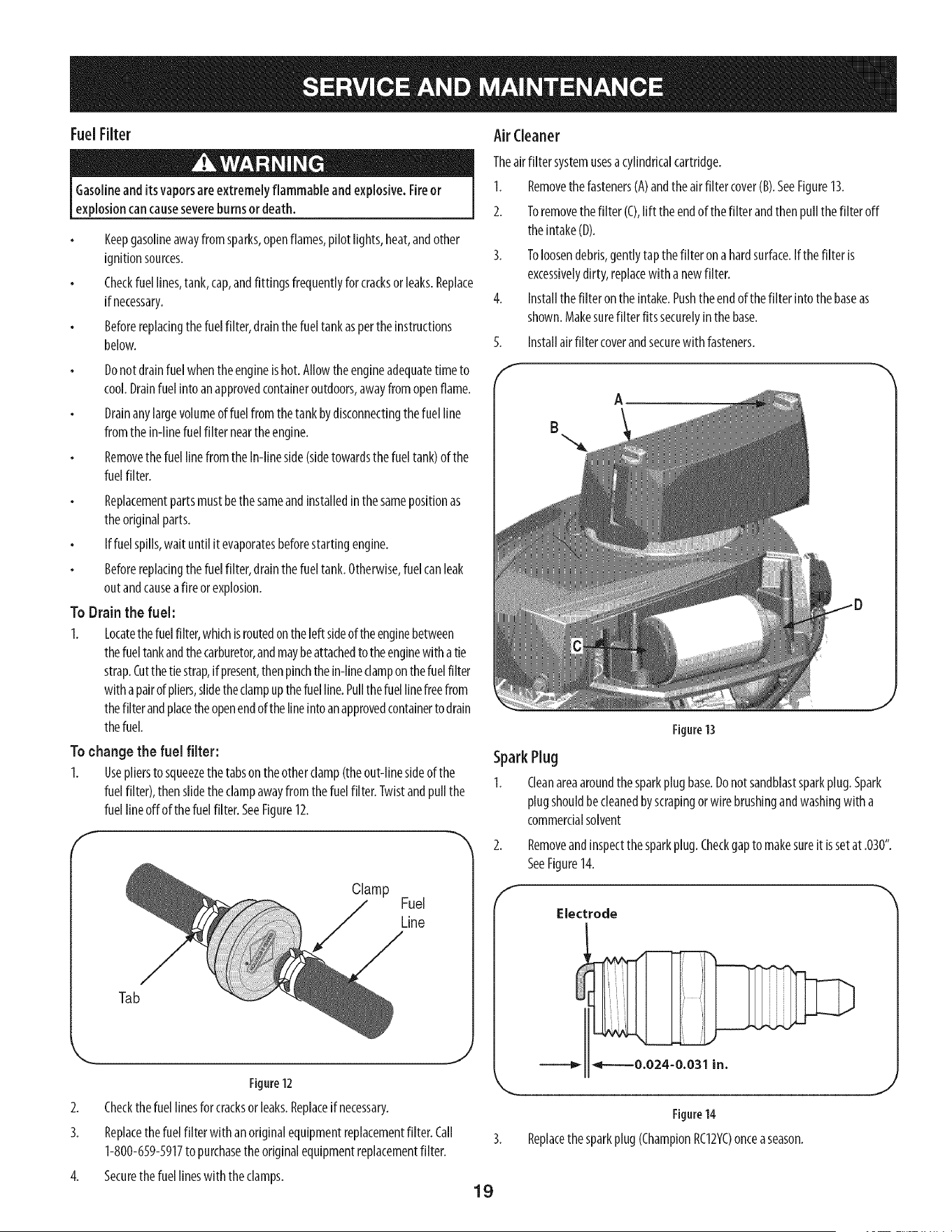
To change the fuel filter:
1. Usepliersto squeezethetabson theotherclamp(theout-linesideof the
fuelfilter), thenslidetheclampawayfromthe fuelfilter. Twistandpullthe
fuel lineoff of thefuel filter.SeeFigure12.
Clamp
Fuel
Line
Tab
Figure12
2. Checkthefuellinesforcracksorleaks.Replaceifnecessary.
3. Replacethe fuel filter with an originalequipmentreplacementfilter. Call
1-800-659-5917to purchasetheoriginalequipmentreplacementfilter.
4. Securethefuel lineswiththe clamps.
AirCleaner
Theairfilter systemusesacylindricalcartridge.
1. Removethefasteners(A)andtheair filtercover(B).SeeFigure13.
2. Toremovethefilter (C),lift theendof thefilter andthenpullthefilter off
theintake(D).
3. Toloosendebris,gentlytapthefilter onahardsurface.If the filter is
excessivelydirty, replacewith a newfilter.
4. Installthe filteronthe intake.Pushtheendof thefilter into the baseas
shown.Makesurefilter fitssecurelyin the base.
Installairfilter coverandsecurewith fasteners.5.
f
SparkPlug
1.
A
Figure 13
Cleanareaaroundthe sparkplugbase.Donotsandblastsparkplug.Spark
plugshouldbecleanedbyscrapingor wire brushingandwashingwith a
commercialsolvent
f
Removeandinspectthe sparkplug.Checkgapto makesureit issetat .030".
SeeFigure14.
Electrode
Figure14
Replacethe sparkplug(ChampionRC12YC)onceaseason.
J
19
Muffler
Temperatureof muffler andnearbyengineareasmay exceed150° F(65°C).
Avoidcontactwith theseareas.
Inspectmufflerperiodically,andreplaceif necessary.Replacementparts
forthemufflermustbethesameandinstalledinthesamepositionasthe
originalparts.
Clean Engine
Dallyorbeforeeveryuse,cleangrass,chafforaccumulateddebrisfrom
engine.Keeplinkage,spring,andcontrolsclean.
Keepareaaroundandbehindmufflerfreeof anycombustibledebris.
Keepingenginecleanallowsair movementaroundengine.
Enginepartsshouldbekeptcleanto reducethe riskof overheatingand
ignitionofaccumulateddebris.
Donotusewater to cleanengineparts. Watercouldcontaminatefuel
system.Usea brush ordry cloth.
CarburetorAdjustment
Thecarburetoronthisengineisnotadjustable.
Lubrication
Beforelubricating, repairing,or inspecting,alwaysdisengagePTO(Blade
EngageLever),moveshift leverinto neutral position, set parkingbrake,stop
eng ne andremovekeyto prevent un ntendedstart ng.
Pivot Points& Linkage
Lubricateall thepivot pointsonthedrivesystem,parkingbrakeandlift linkageat
leastonceaseasonwith light oil.
RearWheels
Therearwheelsshouldberemovedfromtheaxlesonceaseason.Lubricatethe
axlesandtherimswell with anall-purposegreasebeforere-installingthem.
Front Axles
Eachendof thetractor'sfront pivotbarmaybeequippedwith agreasefitting.
Lubricatewith agreasegunafterevery25 hoursof tractoroperation.
Battery
Thebatteryissealedandismaintenance-free.Acidlevelscannotbechecked.
Alwayskeepthebatterycablesandterminalscleanandfreeofcorrosive
build-up.
Aftercleaningthebatteryandterminals,applya lightcoatof petroleumjelly
orgreaseto bothterminals.
Alwayskeeptherubberbootpositionedoverthe positiveterminalto prevent
shorting.
IM PORTANT: If removingthebatteryforanyreason,disconnecttheNEGATIVE
(Black)wirefrom itsterminalfirst, followedbythe POSITIVE(Red)wire.When
re-installingthe battery,alwaysconnectthePOSITIVE(Red)wire to itsterminal
first, followedbytheNEGATIVE(Black)wire. Becertainthat the wiresareconnected
to thecorrectterminals;reversingthem couldchangethe polarityandresultin
damageto yourengine'salternatingsystem.
CleaningBattery
Cleanthe batteryby removingitfrom the tractorandwashingwith abakingsoda
andwatersolution.If necessary,scrapethe batteryterminalswith awire brushto
removedeposits.Coatterminalsandexposedwiringwith greaseorpetroleumjelly
to preventcorrosion.
Battery Failures
Somecommoncausesfor batteryfailureare:
Incorrectinitialactivation
Overcharging
Freezing
Undercharging
Corrodedconnections
ThesefailuresareNOTcoveredbyyourtractor'swarranty.
Cleaning the EngineAndDeck
Anyfueloroil spilledon themachineshouldbewipedoff promptly.DoNOTallow
debristo accumulatearoundthe coolingfinsof theengineor on anyotherpart of
themachine.
IMPORTANT: Theuseofa pressurewasherto cleanyourtractorisNOT
recommended.It maycausedamageto electricalcomponents,spindles,pulleys,
bearingsortheengine.
DeckWashSystemTM
Yourtractor'sdeckisequippedwith awaterport onitssurfaceaspartof itsDeck
WashSystem%followtheseinstructionsto utilizethisfeature.
UsetheDeckWashSystemTM to rinsegrassclippingsfrom the deck'sundersideand
preventthe buildupof corrosivechemicals.Completethe followingstepsAFTER
EACHMOWING:
Drivethetractorto a level,clearspotonyourlawn,nearenoughforyour
gardenhoseto reach.
Makecertainthe tractor'sdischargechuteisdirectedAWAYfrom your house,
garage,parkedcars,etc.
2. Disengagethe PTO(BladeEngage),setthe parkingbrakeandstopthe
engine.
3. Threadthe hosecoupler(packagedwith yourtractor'sOperator'sManual)
ontothe endof yourgardenhose.
4. Attachthehosecouplerto the waterporton the deck'ssurface.SeeFigure
15.
5.
6.
Turnthewateron.
Whilesitting intheoperator'spositiononthe tractor,startthe engineand
placethe throttle leverintheFAST(rabbit)position.
Movethetractor'sPTO(Blade Engage) into theONposition.
2O
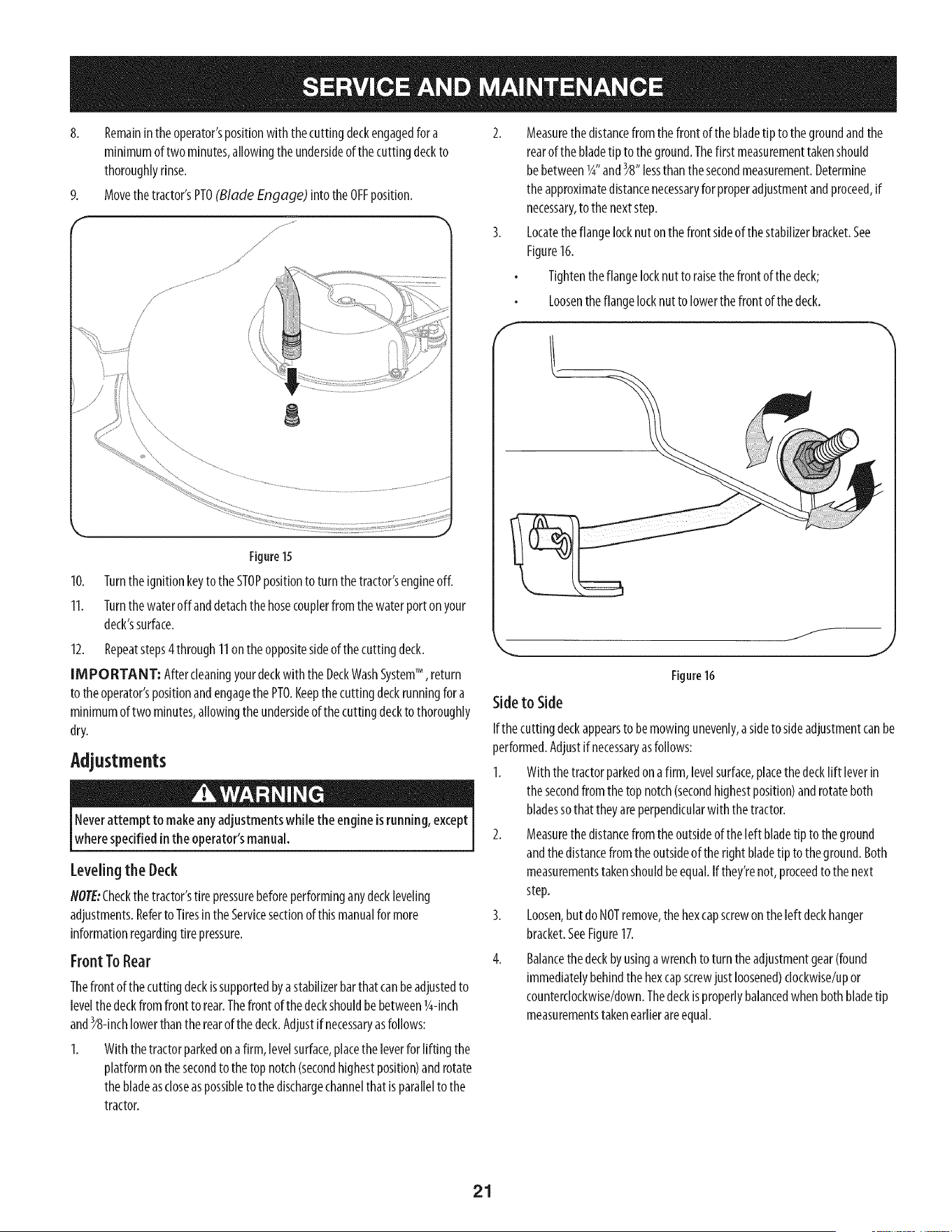
8.
Remainintheoperator'spositionwith thecutting deckengagedfor a
minimumof twominutes,allowingtheundersideof thecuttingdeckto
thoroughlyrinse.
Movethetractor'sPTO(Blade Engage) into the OFFposition.
\
Figure 15
10. Turntheignitionkeyto the STOPpositionto turnthetractor'sengineoff.
11. Turnthewateroff anddetachthehosecouplerfromthewaterport onyour
deck'ssurface.
12. Repeatsteps4through11onthe oppositesideof the cuttingdeck.
IMPORTANT: Aftercleaningyourdeckwith the DeckWashSystemTM , return
to theoperator'spositionandengagethePTO.Keepthecuttingdeckrunningfor a
minimumoftwo minutes,allowingtheundersideof the cuttingdeckto thoroughly
dry.
Adjustments
Neverattempt to makeany adjustmentswhiletheengine is running, except
where specifiedin the operator'smanual.
Levelingthe Deck
NOTE:Checkthetractor'stire pressurebeforeperforminganydeckleveling
adjustments.Referto Tiresin theServicesectionof thismanualformore
informationregardingtire pressure.
Front ToRear
Thefront ofthecuttingdeckissupportedbyastabilizerbarthatcanbeadjustedto
levelthedeckfromfront to rear.Thefront of thedeckshouldbebetween1g-inch
3
andY8-inchlowerthantherearof thedeck.Adjustif necessaryasfollows:
1. With thetractorparkedona firm, levelsurface,placetheleverforlifting the
platformonthe secondto the top notch(secondhighestposition)androtate
thebladeascloseaspossibleto the dischargechannelthat isparalleltothe
tractor.
2. Measurethe distancefromthe front of thebladetip to thegroundandthe
rearof thebladetip tothe ground.Thefirst measurementtakenshould
be betweenlg"and_8" lessthanthe secondmeasurement.Determine
theapproximatedistancenecessaryfor properadjustmentandproceed,if
necessary,to the nextstep.
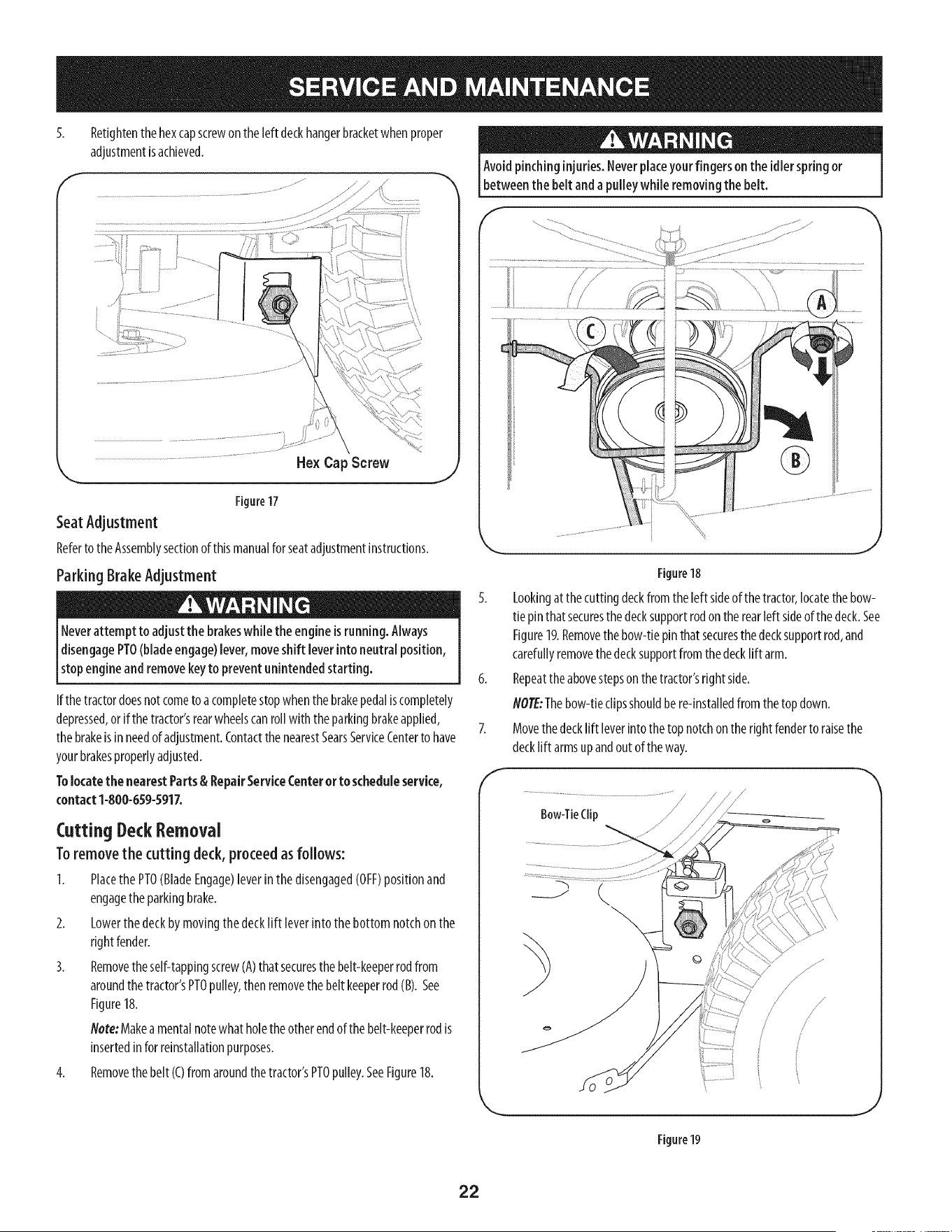
3. Locatetheflangelocknutonthe frontsideof thestabilizerbracket.See
Figure16.
Tightenthe flangelocknutto raisethefront of thedeck;
Loosentheflangelocknutto lowerthefront of the deck.
f__
,,_. J
Figure16
Sideto Side
Ifthe cuttingdeckappearsto be mowingunevenly,asideto sideadjustmentcanbe
performed.Adjustif necessaryasfollows:
1. With the tractorparkedonafirm, levelsurface,placethe decklift leverin
thesecondfromthe topnotch(secondhighestposition)androtateboth
bladessothat theyareperpendicularwith the tractor.
2. Measurethe distancefromthe outsideof the left bladetip to the ground
andthedistancefrom theoutsideof the right bladetip to the ground.Both
measurementstakenshouldbeequal.Ifthey'renot,proceedto thenext
step.
3. Loosen,but do NOTremove,the hex capscrew on the left deck hanger
bracket. See Figure17.
4. Balancethe deck by usinga wrenchto turn the adjustment gear (found
immediately behind the hex capscrewjust loosened)dockwise/up or
counterclockwise/down.Thedeck isproperlybalancedwhen both bladetip
measurements taken earlierare equal.
21
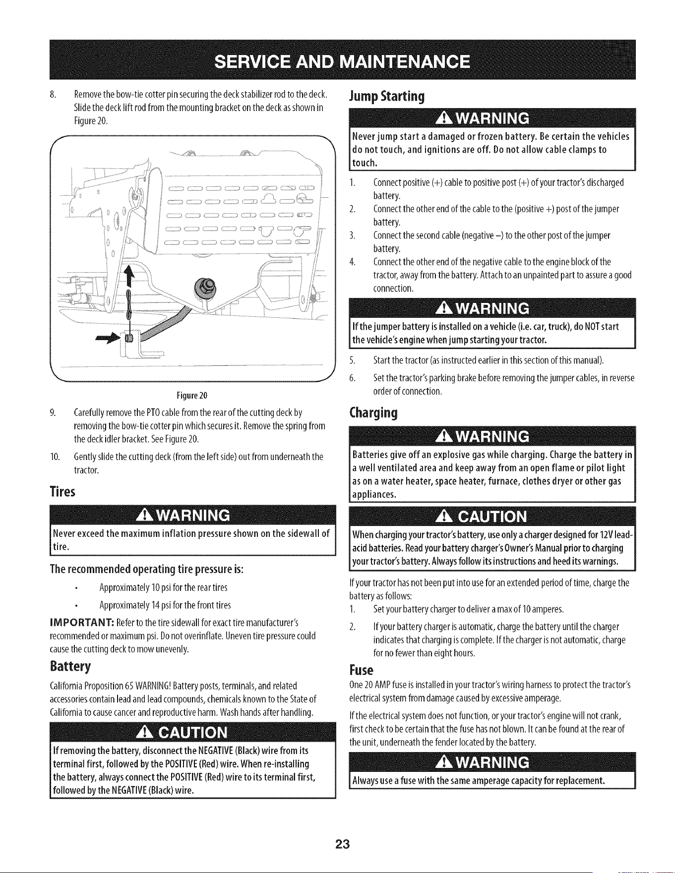
5.
Retightenthehexcapscrewon the left deckhangerbracketwhen proper
adjustmentisachieved.
Hex Cap Screw
J
Figure17
SeatAdjustment
Referto theAssemblysectionof thismanualfor seatadjustmentinstructions.
Parking BrakeAdjustment
Neverattempt to adjust the brakeswhile the engineisrunning. Always
disengagePTO(bladeengage)lever,moveshift leverintoneutral position,
stopengineand removekeyto prevent unintendedstarting.
If the tractordoesnot cometo acompletestopwhenthe brakepedaliscompletely
depressed,or if the tractor'srearwheelscanrollwith the parkingbrakeapplied,
thebrakeisin needof adjustment.ContactthenearestSearsServiceCenterto have
yourbrakesproperlyadjusted.
Tolocatethe nearestParts& RepairService(enter orto scheduleservice,
contact 1-800-659-5917.
Cutting DeckRemoval
Toremovethe cuttingdeck, proceedasfollows:
I. Placethe PTO(BladeEngage)leverinthe disengaged(OFF)positionand
engagethe parkingbrake.
2. Lowerthe deckbymovingthe decklift leverintothe bottomnotchon the
rightfender.
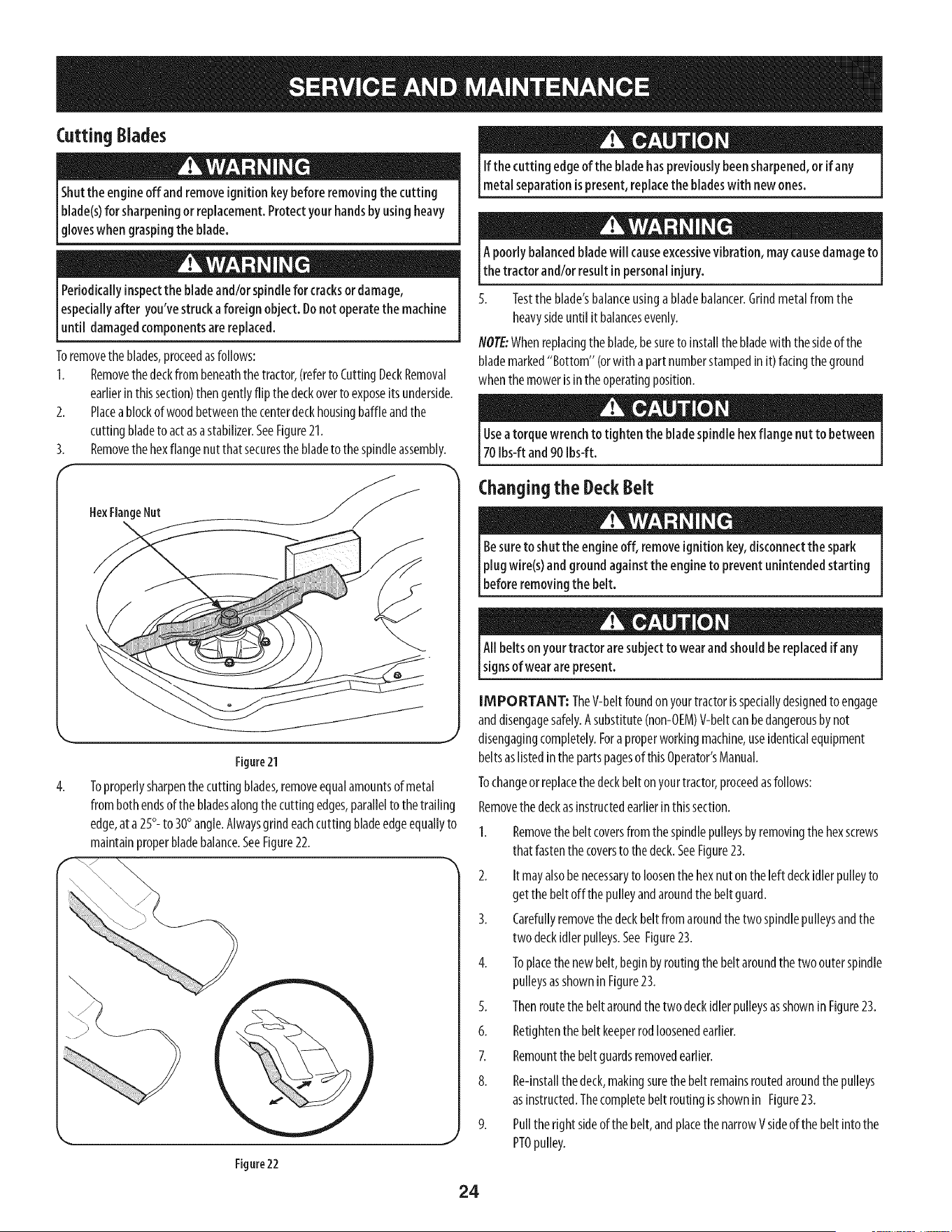
3. Removetheself-tappingscrewCA)thatsecuresthe belt-keeperrodfrom
aroundthe tractor'sPTOpulley,then removethebelt keeperrod(B).See
Figure18.
Note:Makeamentalnotewhat holetheotherendof the belt-keeperrodis
insertedinfor reinstallationpurposes.
4. Removethebelt (C)from aroundthetractor'sPTOpulley.SeeFigure18.
Avoid pinchinginjuries.Neverplaceyourfingers on the idlerspringor
betweenthe belt and apulleywhile removingthe belt.
f
Figure18
5. Lookingatthecuttingdeckfrom theleft sideof thetractor,locatethebow-
tie pinthat securesthe decksupportrodon the rearleft sideofthedeck.See
Figure19.Removethe bow-tie pinthatsecuresthedecksupportrod,and
carefullyremovethedecksupportfromthe decklift arm.
6. Repeattheabovestepson the tractor'sright side.
NOTE:Thebow-tieclipsshouldbere-installedfrom the topdown.
7. Movethedecklift leverinto the topnotchonthe right fenderto raisethe
decklift armsupandoutofthe way.
f
Bow-TieClip
J
Figure19
22
8. Removethebow-tiecotterpinsecuringthedeckstabilizerrodto the deck. JUllIIpStarting
Slidethe decklift rodfromthe mountingbracketon thedeckasshownin
Figure20.
f
.........._y,_ _ ....................
i o
10.
Figure20
CarefullyremovethePTOcablefrom the rearof thecuttingdeckby
removingthe bow-tiecotterpinwhichsecuresit. Removethespringfrom
thedeckidlerbracket.SeeFigure20.
Gentlyslidethe cuttingdeck(fromthe left side)outfrom underneaththe
tractor.
Tires
Neverexceedthe maximum inflation pressureshown on the sidewall of
tire.
Therecommended operating tire pressureis:
Approximately10psifor the reartires
Approximately14psifor thefront tires
IMPORTANT: Referto the tiresidewallforexacttiremanufacturer's
recommendedor maximumpsi.Donotoverinflate.Uneventirepressurecould
causethecuttingdeckto mowunevenly.
Battery
CaliforniaProposition65WARNING!Batteryposts,terminals,andrelated
accessoriescontainleadandleadcompounds,chemicalsknownto the Stateof
Californiato causecancerandreproductiveharm.Washhandsafter handling.
If removingthe battery, disconnectthe NEGATIVE(Black)wire from its
terminal first, followed bythe POSITIVE(Red)wire. Whenre-installing
the battery, alwaysconnectthe POSITIVE(Red)wire to its terminal first,
followed bythe NEGATIVE(Black)wire.
Never jump start a damaged or frozen battery. Be certain the vehicles
do not touch, and ignitions are off. Do not allow cable clamps to
touch.
1. Connectpositive(+) cableto positivepost(+) of yourtractor'sdischarged
battery.
2. Connecttheotherendof the cableto the(positive+) postof thejumper
battery.
3. Connectthesecondcable(negative-) to the otherpostof thejumper
battery.
4. Connecttheotherendof thenegativecableto theengineblockofthe
tractor,awayfrom thebattery.Attachto anunpaintedpartto assureagood
connection.
If the jumper battery is installedon a vehicle(i.e.car,truck),do NOTstart
the vehicle'senginewhenjump starting yourtractor.
5. Startthe tractor(asinstructedearlierinthissectionof thismanual).
6. Setthetractor'sparkingbrakebeforeremovingthe jumpercables,in reverse
orderof connection.
Charging
e
give off an explosive gaswhile charging. Chargethe battery in [
Batteries
a well ventilated areaand keepaway from an open flame or pilot light [
as on a water heater, spaceheater, furnace, clothes dryer or other gas [
lapp ances. J
Whenchargingyourtractor'sbattery, useonlyachargerdesignedfor 12Vlead-
[acidbatteries.Readyourbatterycharger'sOwner'sManualpriorto charging
[your tractor s battery.Alwaysfollow its instructionsandheedits warnings.
Ifyourtractorhasnot beenputinto useforanextendedperiodof time,chargethe
batteryasfollows:
1. Setyourbatterychargerto delivera maxof 10amperes.
2. Ifyourbatterychargerisautomatic,chargethebatteryuntilthe charger
indicatesthatchargingiscomplete.If thechargerisnotautomatic,charge
for nofewerthaneighthours.
Fuse
One20AMPfuseisinstalledinyourtractor'swiring harnessto protectthe tractor's
electricalsystemfromdamagecausedbyexcessiveamperage.
Ifthe electricalsystemdoesnot function,oryourtractor'senginewill not crank,
first checkto becertainthatthe fusehasnotblown.It canbefoundat therearof
theunit, underneaththe fenderlocatedbythe battery.
Alwaysusea fusewith thesameamperagecapacityfor replacement.
23
CuttingBlades
Shutthe engineoffand removeignitionkeybeforeremoving the cutting
blade(s)for sharpeningor replacement.Protectyour handsby usingheavy
[g oveswhen graspng the b ade.
Periodicallyinspectthe bladeand/orspindlefor cracksor damage,
Iespeciallyafter you'vestruckaforeign object. Donot operatethe machine
[until damagedcomponentsarereplaced.
Toremovetheblades,proceedasfollows:
1. Removethedeckfrom beneaththetractor,(referto CuttingDeckRemoval
earlierinthissection)thengentlyflip the deckoverto exposeitsunderside.
2. Placeablockof woodbetweenthecenterdeckhousingbaffleandthe
cuttingbladeto actasastabilizer.SeeFigure21.
3. Removethehexflangenutthatsecuresthe bladeto the spindleassembly.
HexFlangeNut
4.
Figure21
\
Toproperlysharpenthecutting blades,removeequalamountsof metal
from bothendsofthe bladesalongthe cuttingedges,parallelto the trailing
edge,ata 25°- to 30° angle.Alwaysgrindeachcuttingbladeedgeequallyto
maintainproperbladebalance.SeeFigure22.
Figure22
If the cutting edge of the bladehaspreviouslybeensharpened,orif any
metalseparationispresent,replacethe bladeswith new ones.
A poorly balancedbladewill causeexcessivevibration, maycausedamageto
the tractor and/or resultin personalinjury.
5. Testtheblade'sbalanceusingabladebalancer.Grindmetalfromthe
heavysideuntil it balancesevenly.
NOTE:Whenreplacingthe blade,besureto installthe bladewith the sideof the
blademarked"Bottom" (orwitha part numberstampedinit) facingthe ground
whenthemowerisin theoperatingposition.
Useatorque wrench to tighten the bladespindlehexflange nut to between
70Ibs-ft and 90 Ibs-ft.
Changing the DeckBelt
Besureto shut the engineoff, removeignitionkey,disconnectthe spark
plugwire(s)and groundagainst the engineto prevent unintendedstarting
beforeremovingthe belt.
All belts onyour tractor aresubjectto wear andshouldbereplacedif any
signsof wearare present.
IMPORTANT: TheV-beltfoundon yourtractorisspeciallydesignedto engage
anddisengagesafely.Asubstitute(non-OEM)V-beltcanbedangerousbynot
disengagingcompletely.Fora properworkingmachine,useidenticalequipment
beltsaslistedinthe partspagesof thisOperator'sManual.
Tochangeorreplacethe deckbelt onyourtractor,proceedasfollows:
Removethe deckasinstructedearlierinthissection.
1. Removethebeltcoversfrom thespindlepulleysbyremovingthehexscrews
that fastenthecoversto thedeck.SeeFigure23.
2. It mayalsobe necessaryto loosenthe hexnut on the left deckidlerpulleyto
getthe belt offthe pulleyandaroundthebeltguard.
3. Carefullyremovethedeckbelt fromaroundthe two spindlepulleysandthe
two deckidler pulleys.SeeFigure23.
4. Toplacethenewbelt,beginbyroutingthebelt aroundthetwo outerspindle
pulleysasshownin Figure23.
5. Thenroutethe beltaroundthe twodeckidlerpulleysasshownin Figure23.
6. Retightenthe beltkeeperrodloosenedearlier.
7. Remountthe beltguardsremovedearlier.
8. Re-installthedeck,makingsurethe belt remainsroutedaroundthepulleys
asinstructed.Thecompletebelt routingisshownin Figure23.
9. Pullthe rightsideof thebelt,andplacethenarrowVsideof thebelt intothe
PTOpulley.
24
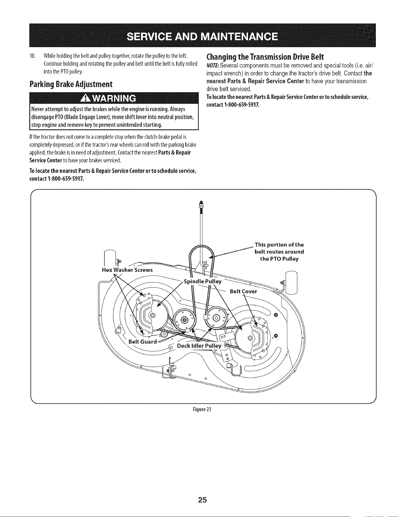
10. Whileholdingthebelt andpulleytogether,rotatethepulleyto the left.
Continueholdingandrotatingthe pulleyandbelt untilthebelt isfully rolled
into thePTOpulley.
ParkingBrakeAdjustment
Neverattempt to adjust the brakeswhile the engine isrunning. Always
disengagePTO(BladeEngageLever),moveshift [everintoneutralposition,
stopengine andremovekeyto prevent unintendedstarting.
(:hanging the TransmissionDrive Belt
NOTE:Several components must be removed and special tools (i.e. air/
impact wrench) in order to change the tractor's drive belt. Contact the
nearest Parts & Repair Service Center to have your transmission
drive belt serviced.
Tolocatethe nearestParts& RepairService(:enteror to scheduleservice,
contact1-800-659-5917.
If the tractordoesnotcometoa completestopwhentheclutch-brakepedalis
completelydepressed,orif thetractor'srearwheelscanrollwith theparkingbrake
applied,the brakeis in needof adjustment.Contactthe nearestParts& Repair
ServiceCenterto haveyourbrakesserviced.
Tolocate the nearestParts& RepairServiceCenter or to schedule service,
contact1-800-659-5917.
F
Figure 23
J
25
Neverstore lawn tractor with fuel in tank indoorsorin poorlyventilated
areaswherefuel fumes mayreachanopen flame, spark,or pilot light ason
a furnace,water heater,clothesdryer,or gasappliance.
PreparingTheEngine
IM PORTANT: Fuelleft inthefueltankduringwarmweatherdeterioratesand
will causeseriousstartingproblems.
Topreventgumdepositsfromforminginsidetheengine'scarburetorandcausing
possiblemalfunctionofthe engine,thefuel systemmustbeeithercompletely
emptied,or thegasolinemustbetreatedwith astabilizerto preventdeterioration.
I. Ifusingafuelstabilizer:
a. Readthe productmanufacturer'sinstructionsandrecommendations.
b. Addto clean,freshgasolinethecorrectamountof stabilizerfor the
capacityofthe fuel system.
c. Fillthefueltankwith treatedfuel andruntheenginefor2-3minutesto
getstabilizedfuel into thecarburetor.
2. Ifemptyingthefuelsystem:
a. Donotdrainfuel whentheengineishot.Allowtheengineadequate
timeto cool.Drainfuel into anapprovedcontaineroutdoors,awayfrom
openflame.
b. Drainanylargevolumeof fuelfromthe tankbydisconnectingthe
fuel linefromthe in-linefuelfilter neartheengine.Seethecomplete
instructionsforDrainingTheFuellaterin thissection.
Gasolineisextremely flammable and canbe explosiveundercertain
conditions.Draingasolinebeforestoringthe equipment for extended
periods.Drainfuel only into an approvedcontaineroutdoors,awayfrom
an open flame. Allow engine to cool.Extinguishcigarettes,cigars,pipes,
and othersourcesof ignition prior to draining fuel. Storegasolinein an
approvedcontainer in safelocation.
c. Reconnectthe fuel lineandrunthe engineuntil it startsto falter,then
usethe choketo keeptheenginerunninguntilall fuelinthecarburetor
hasbeenexhausted.
d. Disconnectthefuellineanddrainanyremaininggasolinefrom the
system.
DrainingThe Fuel
1. Locatethefuel filter,whichis locatedon theleft sideoftheengine,andmay
beattachedto theenginewith a tiestrap.
2. Cutthe tie strap,if present,thenpinchthe in-lineclamponthefuel filter
with a pairof pliers,slidetheclampupthefuel line.
3. Pullthefuel linefreefrom the filterandplacetheopenendof the lineinto
an approvedcontainerto drainthefuel.
PreparingThelawn tractor
Cleanandlubricatetractorthoroughlyasdescribedinthelubrication
instructions.
2. Donotusea pressurewasherorgardenhoseto cleanyourunit.
3. Storemowerinadry,cleanarea.Donotstorenextto corrosivematerials,
suchasfertilizer.
Gasolineisa toxicsubstance.Disposeofgasolineproperly.Contactyour
localauthorities for approveddisposalmethods.
3. Removethe sparkplugandpourone(1)ounceofengineoil throughthespark
plugholeinto the cylinder.Crankthe engineseveraltimesto distributethe
oil. Replacethesparkplug.
26
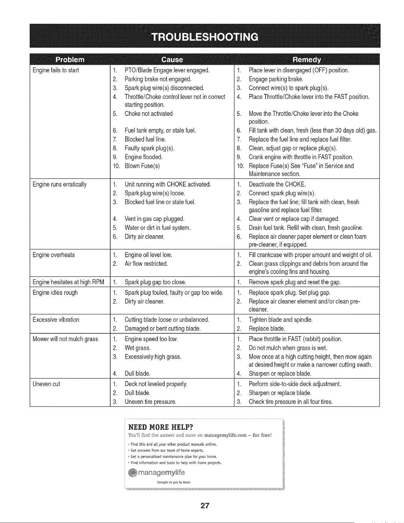
Enginefailsto start
Enginerunserratically
1. PTO/BladeEngageleverengaged.
2. Parkingbrakenotengaged.
3. Sparkplugwire(s) disconnected.
4. Throttle/Chokecontrollevernot incorrect
startingposition.
5. Chokenotactivated
6. Fueltank empty,or stalefuel.
7. Blockedfuel line.
8. Faultysparkplug(s).
9. Engineflooded.
10. BlownFuse(s)
1. UnitrunningwithCHOKEactivated.
2. Sparkplugwire(s) loose.
3. Blockedfuel lineor stalefuel.
4. Ventingas cap plugged.
5. Wateror dirt in fuel system.
6. Dirtyair cleaner.
Engineoverheats 1. Engineoil levellow. 1.
2. Air flowrestricted. 2.
Enginehesitatesat high RPM 1. Sparkpluggaptoo close. 1.
Engineidles rough 1. Sparkplugfouled,faultyor gap too wide. 1.
2. Dirtyair cleaner. 2.
Excessivevibration
Mowerwill not mulchgrass
Unevencut
1. Cuttingbladelooseor unbalanced.
2. Damagedorbent cuttingblade.
1. Enginespeedtoo low.
2. Wetgrass.
3. Excessivelyhighgrass.
4. Dullblade.
1. Decknot leveledproperly.
2. Dullblade.
3. Uneventire pressure.
1. Placeleverindisengaged(OFF) position.
2. Engageparkingbrake.
3. Connectwire(s)to sparkplug(s).
4. PlaceThrottle/Chokeleverintothe FASTposition.
5. MovetheThrottle/Chokeleverintothe Choke
position.
6. Filltank with clean,fresh (less than 30days old) gas.
7. Replacethe fuel lineandreplacefuel filter.
8. Clean,adjustgapor replaceplug(s).
9. Crankenginewiththrottlein FASTposition.
10. ReplaceFuse(s)See"Fuse"in Serviceand
Maintenancesection.
1. Deactivatethe CHOKE.
2. Connectsparkplugwire(s).
3. Replacethe fuel line;fill tankwithclean,fresh
gasolineandreplacefuel filter.
4. Clearventor replacecap if damaged.
5. Drainfuel tank. Refillwithclean,fresh gasoline.
6. Replaceair cleanerpaperelementor cleanfoam
pre-cleaner,if equipped.
Fillcrankcasewithproperamountandweightof oil.
Cleangrassclippingsanddebrisfrom aroundthe
engine'scoolingfinsandhousing.
Removesparkplugandresetthe gap.
Replacespark plug.Set pluggap.
Replaceair cleanerelementand/orcleanpre-
cleaner.
1. Tightenbladeand spindle.
2. Replaceblade.
1. Placethrottlein FAST(rabbit)position.
2. Do notmulchwhen grassis wet.
3. Mowonceat a highcuttingheight,then mowagain
at desiredheightor makea narrowercuttingswath.
4. Sharpenor replaceblade.
1. Performside-to-sidedeckadjustment.
2. Sharpenor replaceblade.
3. Checktire pressurein all four tires.
NEED MORE HELP?
Find this and a[[ your other product manuals online.
Get answers from our team of home experts.
Get a personalized maintenance ptan for your home.
Find information and tools to help with home projects.
27
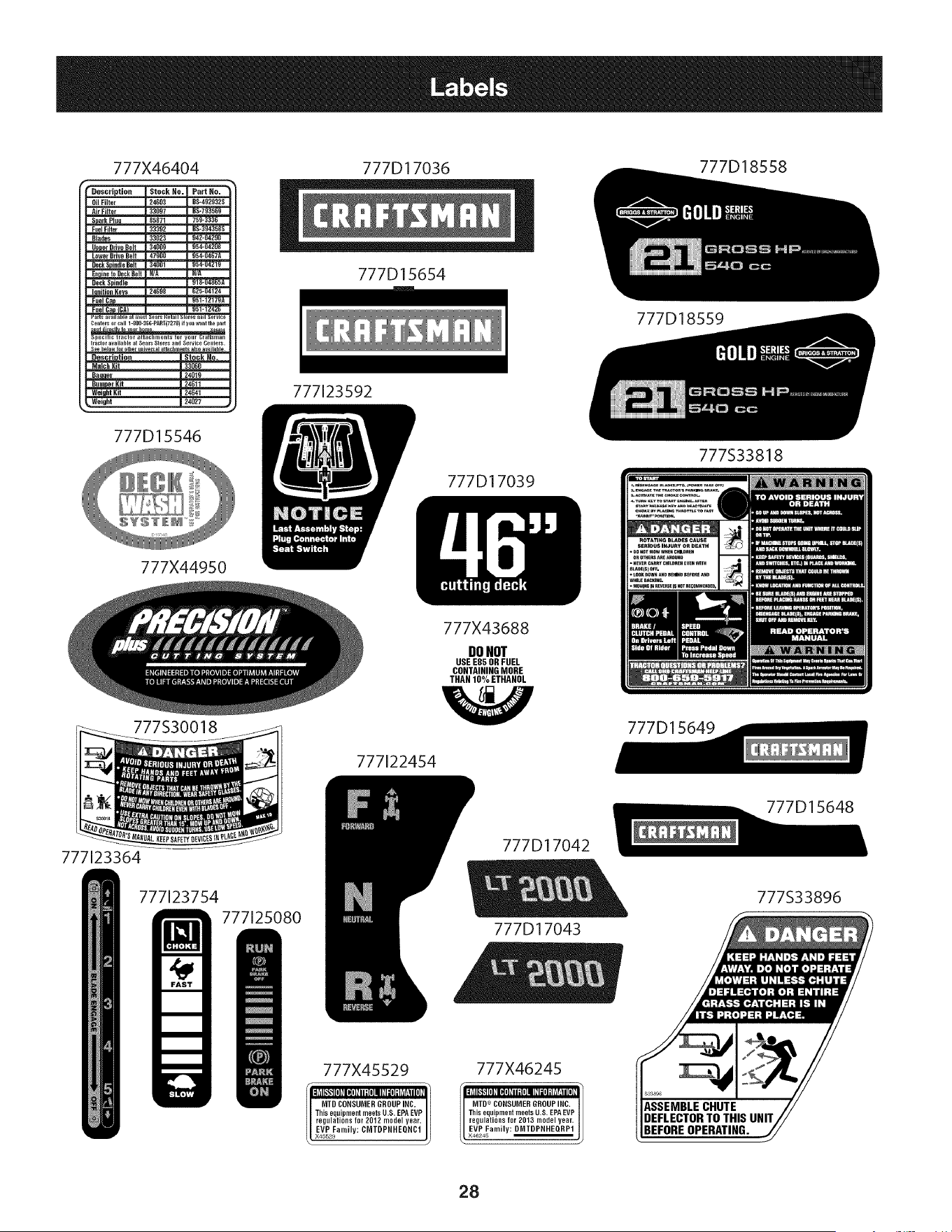
777X46404 777D18558
Ce.tersorcall1-800-366-PART(7278)if yo.wanttilepart
i specmc tractor attachlnent_ lot yo.r Crattslnan
tractoravailableat SearsStoresandService Cenlers.
Seebelowfor otheru,i_e_al atladlmentsal_o availahlem
Descr|_tjon Stock Ho.
BumperKit | 24011
WeightKit [ 24041
_. Weight | 24027 ,
777D15546
777X44950
777S30018
777D17036
777D15654
777123592
777D17039
777X43688
DONOT
USE E85 OR FUEL
CONTAINING MORE
THAN 10% ETHANOL
777[22454
777D18559
777S33818
777D15649
777123364
777123754
777125080
777X45529
W Ik ILIII i I:W: IL
II MTD CONSUMER GROUPINC.
This equipnlent meets U.S. EPA EVP
regulations for 2012 model year.
[EVP Family: CMTDPRHEQRC1
X45529
777D17042
777D17043
777X46245
MTD CONSUMER GROUPINC.
This equipment meets U.S. EPAEVP
regulations for 2013 model year,
L X46245
BEFOREOPERATING.
777D15648
777S33896
28

This page intentionally left blank. Use this page to make any notes regarding your tractor.
29
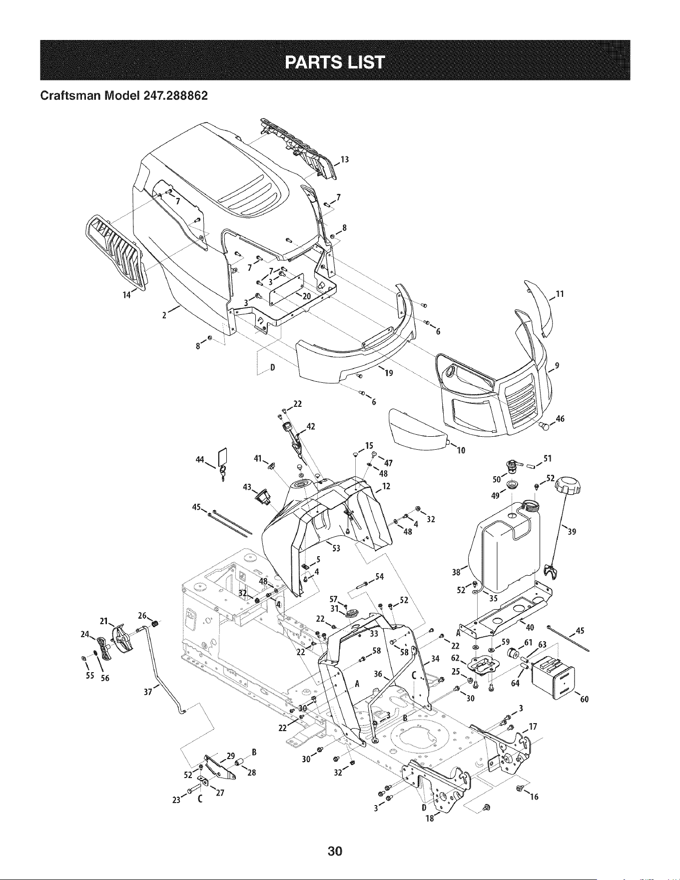
Craftsman IViodel 247.288862
6
10
32
22
6O
3O
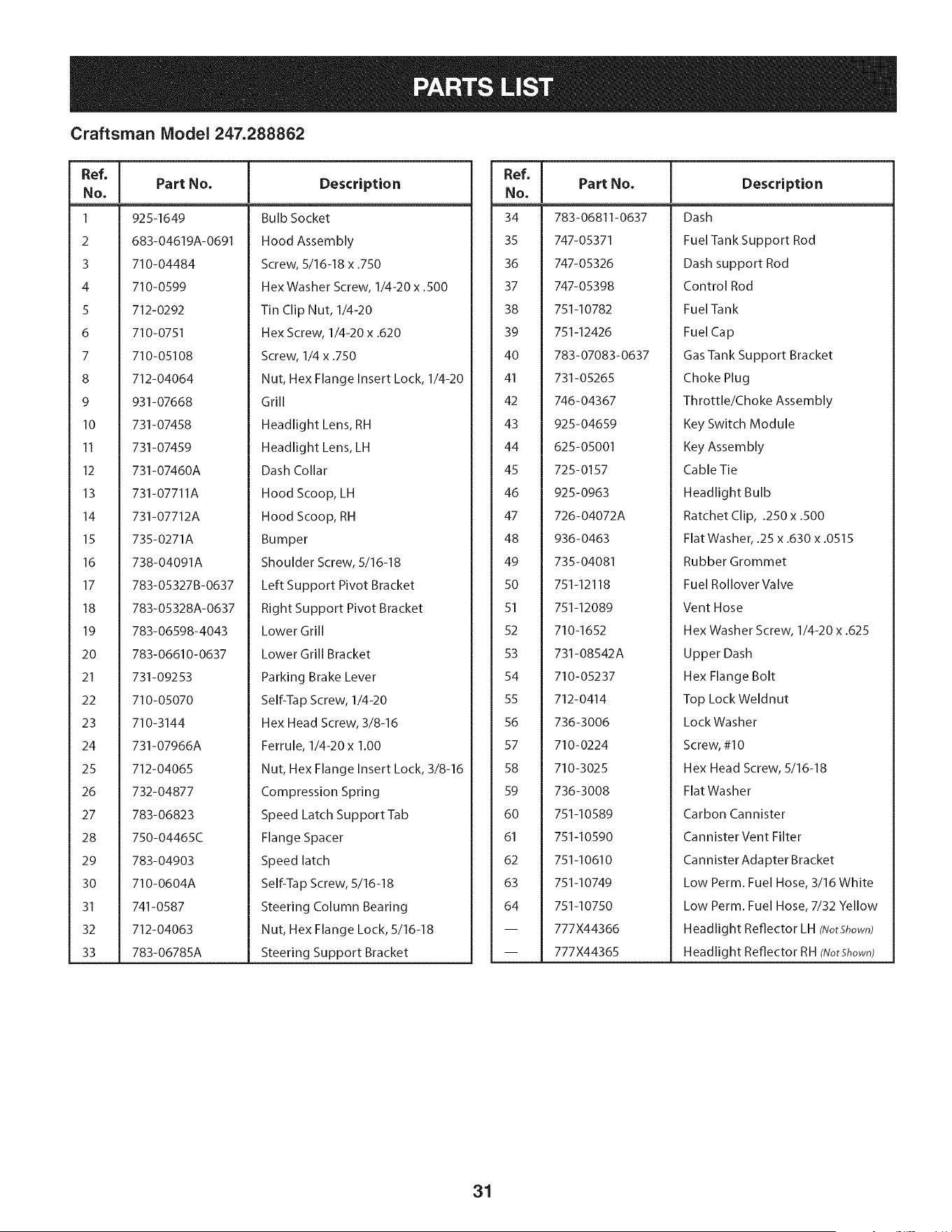
Craftsman Model 247.288862
Ref, I
No,
1 925-1649
2 683-04619A-0691
3 710-04484
4 710-0599
5 712-0292
6 710-0751
7 710-05108
8 712-04064
9 931-07668
10 731-07458
II 731-07459
12 731-07460A
13 731-07711A
14 731-07712A
15 735-0271A
16 738-04091A
17 783-05327B-0637
18 783-05328A-0637
19 783-06598-4043
20 783-06610-0637
21 731-09253
22 710-05070
23 710-3144
24 731-07966A
25 712-04065
26 732-04877
27 783-06823
28 750-04465C
29 783-04903
30 710-0604A
31 741-0587
32 712-04063
33 783-06785A
Part No, Description
Bulb Socket
Hood Assembly
Screw, 5/16-18 x .750
Hex Washer Screw, 1/4-20 x .500
Tin Clip Nut, 1/4-20
Hex Screw, 1/4-20 x .620
Screw, 1/4 x .750
Nut, Hex Flange Insert Lock, 1/4-20
Grill
Headlight Lens, RH
Headlight Lens, LH
Dash Collar
Hood Scoop, LH
Hood Scoop, RH
Bumper
Shoulder Screw, 5/16-18
Left Support Pivot Bracket
Right Support Pivot Bracket
Lower Grill
Lower Grill Bracket
Parking Brake Lever
Self-Tap Screw, 1/4-20
Hex Head Screw, 3/8-16
Ferrule, 1/4-20 x 1.00
Nut, Hex Flange Insert Lock, 3/8-16
Compression Spring
Speed Latch Support Tab
Flange Spacer
Speed latch
Self-Tap Screw, 5/16-18
Steering Column Bearing
Nut, Hex Flange Lock, 5/16-18
Steering Support Bracket
Ref, [
No,
34 783-06811-0637
35 747-05371
36 747-05326
37 747-05398
38 751-10782
39 751-12426
40 783-07083-0637
41 731-05265
42 746-04367
43 925-04659
44 625-05001
45 725-0157
46 925-0963
47 726-04072A
48 936-0463
49 735-04081
50 751-12118
51 751-12089
52 710-1652
53 731-08542A
54 710-05237
55 712-0414
56 736-3006
57 710-0224
58 710-3025
59 736-3008
60 751-10589
61 751-10590
62 751-10610
63 751-10749
64 751-10750
-- 777X44366
-- 777X44365
Part No, Description
Dash
Fuel Tank Support Rod
Dash support Rod
Control Rod
FuelTank
Fuel Cap
Gas Tank Support Bracket
Choke Plug
Throttle/Choke Assembly
Key Switch Module
Key Assembly
Cable Tie
Headlight Bulb
Ratchet Clip, .250 x .500
Flat Washer, .25 x .630 x .0515
Rubber Grommet
Fuel Rollover Valve
Vent Hose
Hex Washer Screw, 1/4-20 x .625
Upper Dash
Hex Flange Bolt
Top Lock Weldnut
LockWasher
Screw, #10
Hex Head Screw, 5/16-18
Flat Washer
Carbon Cannister
Cannister Vent Filter
Cannister Adapter Bracket
Low Perm. Fuel Hose, 3/16 White
Low Perm. Fuel Hose, 7/32 Yellow
Headlight Reflector LH (NotShown)
Headlight Reflector RH (NotShown)
31
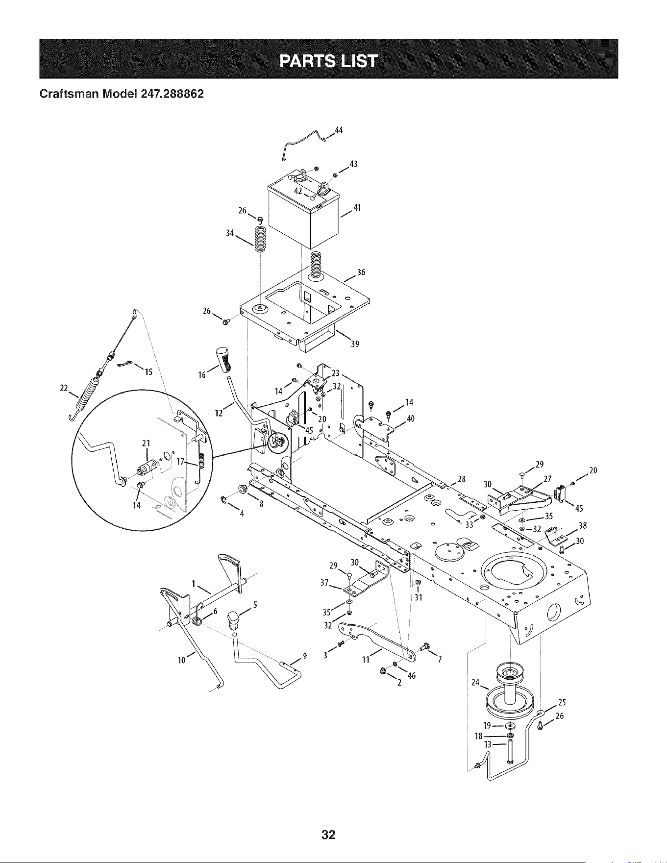
Craftsman Model 247.288862
36
22
21
14
12
39
40
30
45
38
32
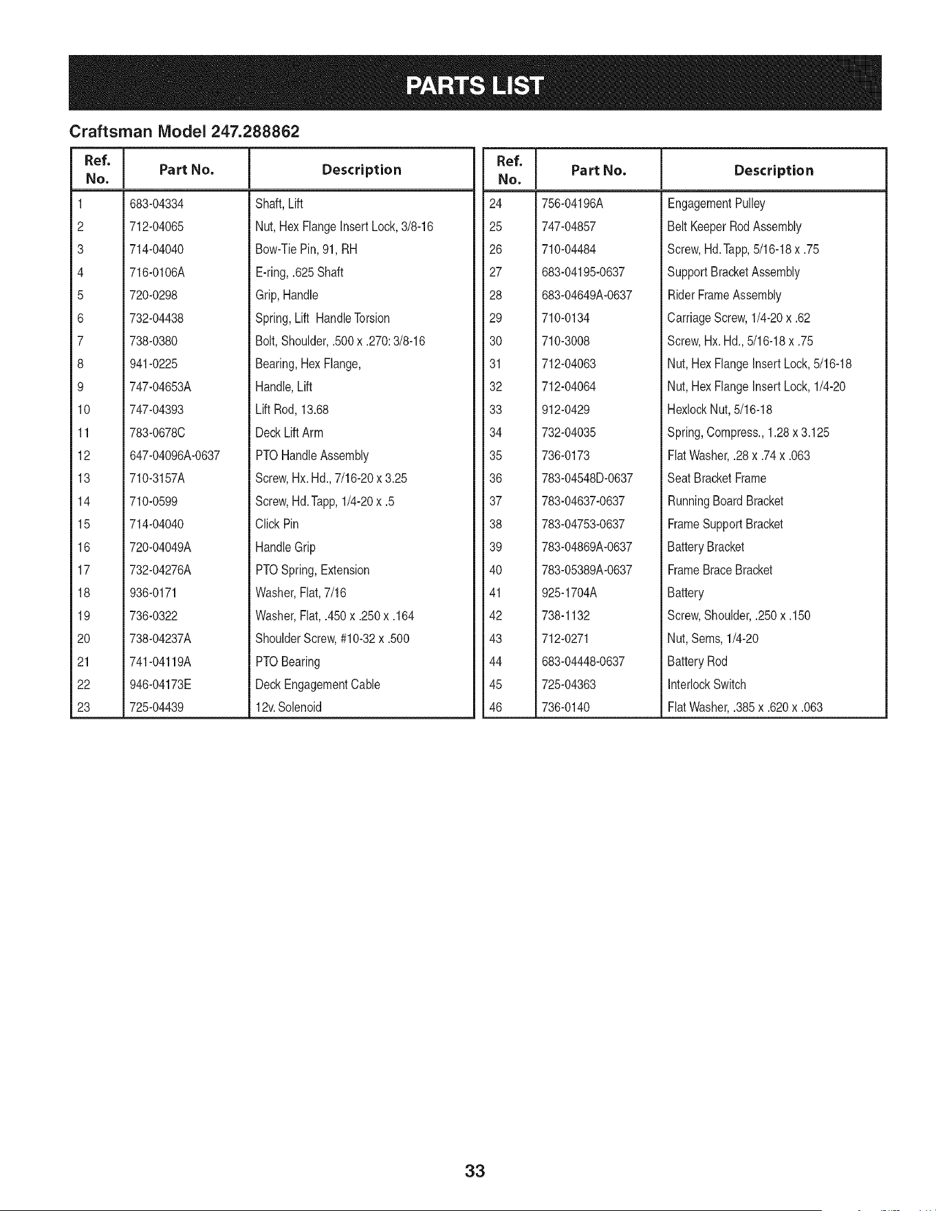
Craftsman Model 247.288862
I
Ref.
I Part No.
No,
I
1 683-04334
2 712-04065
3 714-04040
4 716-0106A
5 720-0298
6 732-04438
7 738-0380
8 941-0225
9 747-04653A
10 747-04393
11 783-0678C
12 647-04096A-0637
13 710-3157A
14 710-0599
15 714-04040
16 720-04049A
17 732-04276A
18 936-0171
19 736-0322
20 738-04237A
21 741-04119A
22 946-04173E
23 725-04439
Description
Shaft,Lift
Nut,Hex FlangeInsert Lock,3/8-16
Bow-TiePin,91, RH
E-ring,.625Shaft
Grip,Handle
Spring,Lift HandleTorsion
Bolt, Shoulder,.500x .270:3/8-16
Bearing,HexFlange,
Handle,Lift
Lift Rod, 13.68
DeckLiftArm
PTOHandleAssembly
Screw,Hx.Hd., 7/16-20x 3.25
Screw,Hd.Tapp,1/4-20x .5
ClickPin
HandleGrip
PTOSpring,Extension
Washer,Flat,7/16
Washer,Fiat,.450x .250x .164
ShoulderScrew,#10-32x .500
PTOBearing
DeckEngagementCable
12v.Solenoid
Ref. I
NO,
24 756-04196A
25 747-04857
26 710-04484
27 683-04195-0637
28 683-04649A-0637
29 710-0134
30 710-3008
31 712-04063
32 712-04064
33 912-0429
34 732-04035
35 736-0173
36 783-04548D-0637
37 783-04637-0637
38 783-04753-0637
39 783-04869A-0637
40 783-05389A-0637
41 925-1704A
42 738-1132
43 712-0271
44 683-04448-0637
45 725-04363
46 736-0140
Part No. Description
EngagementPulley
Belt KeeperRodAssembly
Screw,Hd.Tapp,5/16-18x .75
SupportBracketAssembly
RiderFrameAssembly
CarriageScrew,1/4-20x .62
Screw,Hx. Hd.,5/16-18x .75
Nut, HexFlangeInsertLock,5/16-18
Nut, HexFlangeInsertLock,1/4-20
HexlockNut, 5/16-18
Spring,Compress.,1.28x3.125
FlatWasher,.28x .74x .063
Seat BracketFrame
RunningBoardBracket
FrameSupportBracket
BatteryBracket
FrameBraceBracket
Battery
Screw,Shoulder,.250x .150
Nut, Sems,1/4-20
BatteryRod
InterlockSwitch
FlatWasher,.385x .620x .063
33
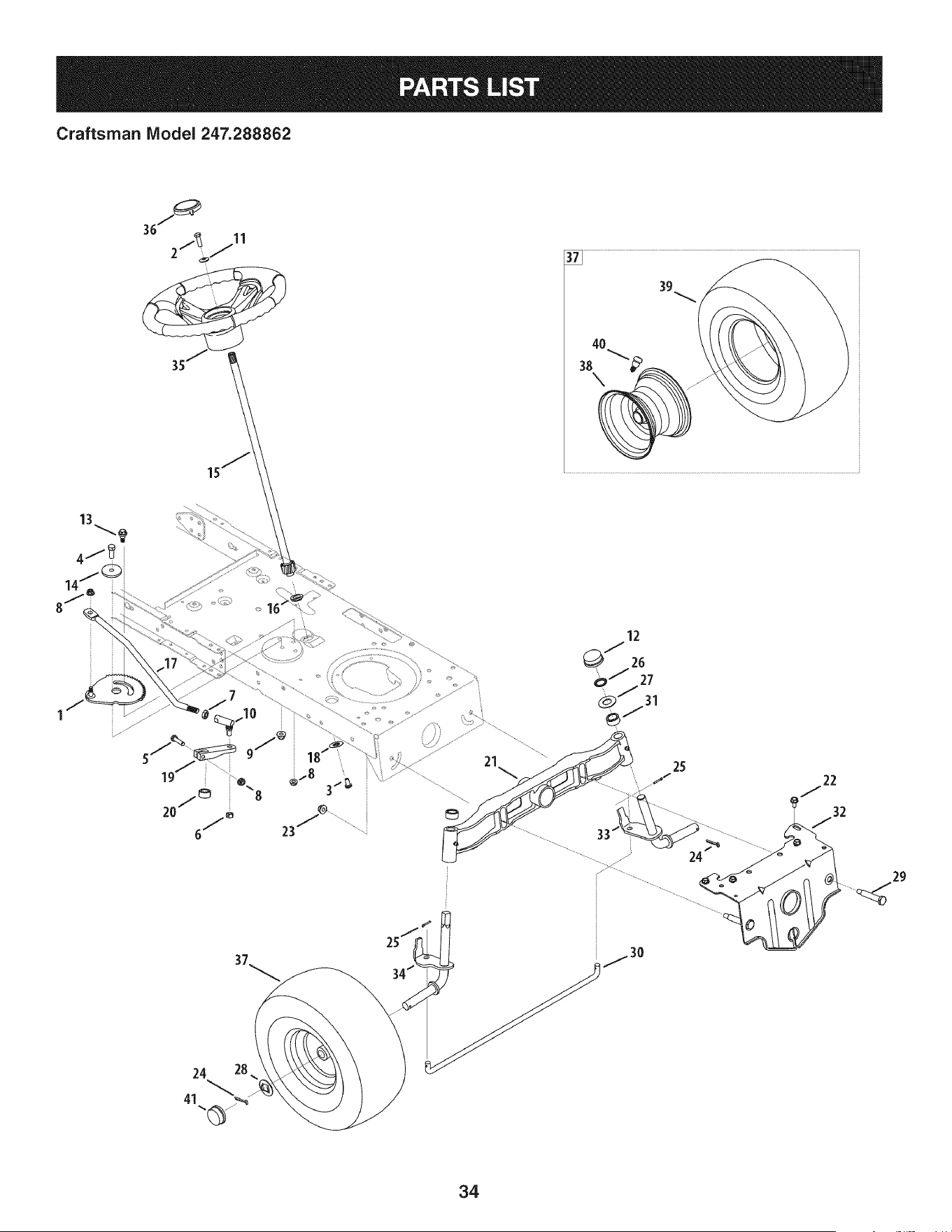
Craftsman IViodel 247.288862
3s\_4°_ __\\\\\_
I
24
29
37_ 2s/_
34/
24 28 !
41 _
34

Craftsman Model 247.288862
Ref, I
No,
1 617-04094
2 710-0643
3 710-1309
4 710-0514
5 710-3180
6 912-0214
7 912-0240
8 712-04063
9 712-04065
10 923-0448A
11 736-0242
12 731-04693
13 738-04141
14 738-04162C
15 738-0919A
16 941-04124
17 747-05385
18 948-0389
19 748-04278
20 748-04068
21 719-04177A
Part No. Description
Gear Assembly, Steering
Screw, 5/16-18, 1.00, Gr5, Lock
Screw, Mach, 5/16-18, 0.750
Hex Head Screw, 3/8-16 x 1.00
Screw, 5/16-18, 1.75, Gr5
Nut, Jam Lock, 3/8-24
Nut, Jam, 7/16-20, Gr2
Nut, Flange Lock, 5/16-18, Grf
Nut, Flange Lock, 3/8-16, Grf
Ball Joint, 7/16-20, Lock
Washer, Bell, .340 x .872 x .060
Hub Cap
Shoulder Screw, 5/16-18
Shoulder Spacer, .8840 x .190
Steering Shaft, 5/8 Spline x 21.86
Bearing, Flange, Hex 5/8
Drag Link, Steering
Cap, 1.25 x .16
Steering, Block
Spacer, .710 ID x .125 OD x .56
Pivot Bar Axle Assembly
Ref, I
No,
22 710-04484
23 712-04065
24 714-0162
25 914-0474
26 726-04035
27 936-0316
28 736-04228A
29 738-04128
30 747-04299A
31 748-04068
32 783-05326B-0637
33 938-04013
34 938-04014A-0637
35 631-04008A
36 731-06825
37 634-05067-0961
38 934-05066-4042
39 734-1731-0901
40 934-0255
41 931-0484A
Part No, Description
Screw, 5/16-18, 0.750
Nut, Flange Lock, 3/8-16, GrF
Pin, Cotter, 5/32, 1.25
Pin, Cotter, 1/8 x 0.75
Push Cap, 3/4
Washer, Flat, .78 x 1.59 x .060
Washer, Flat, .781 x 1.59
Screw, Shlder, .500 x 2.380, 3/8-16
Tie Rod
Spacer, .71 x .125 x .56
Pivot Bar Bracket
Axle Assembly LH
Axle Assembly RH
Steering Wheel, Standard Grip
Cap, Steering Wheel (Crafts. logo)
Wheel Assembly
Rim
Tire, 15 x 6 x 6 Sq. Shoulder
Valve Stem
Hub Cap
35
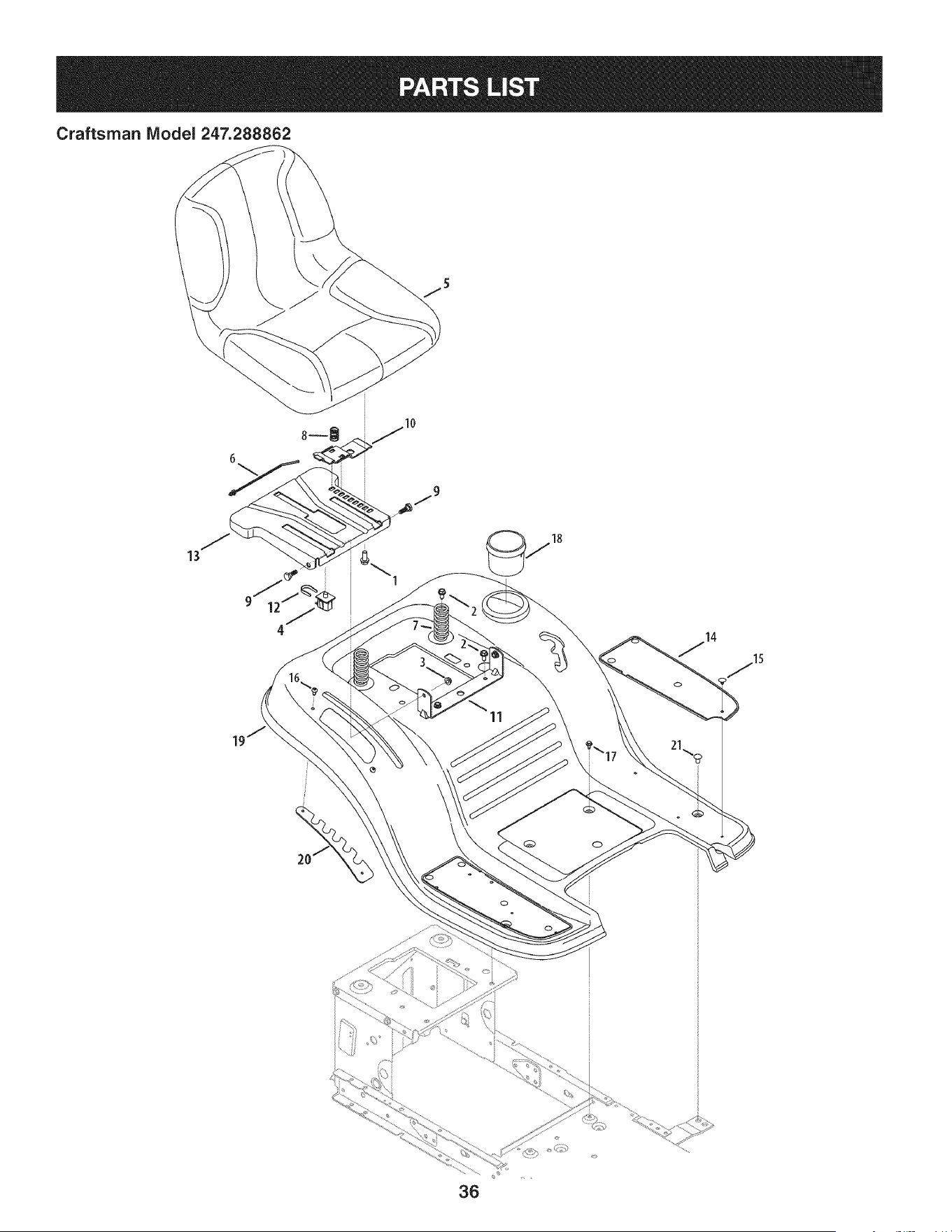
Craftsman Model 247.288862
\
11
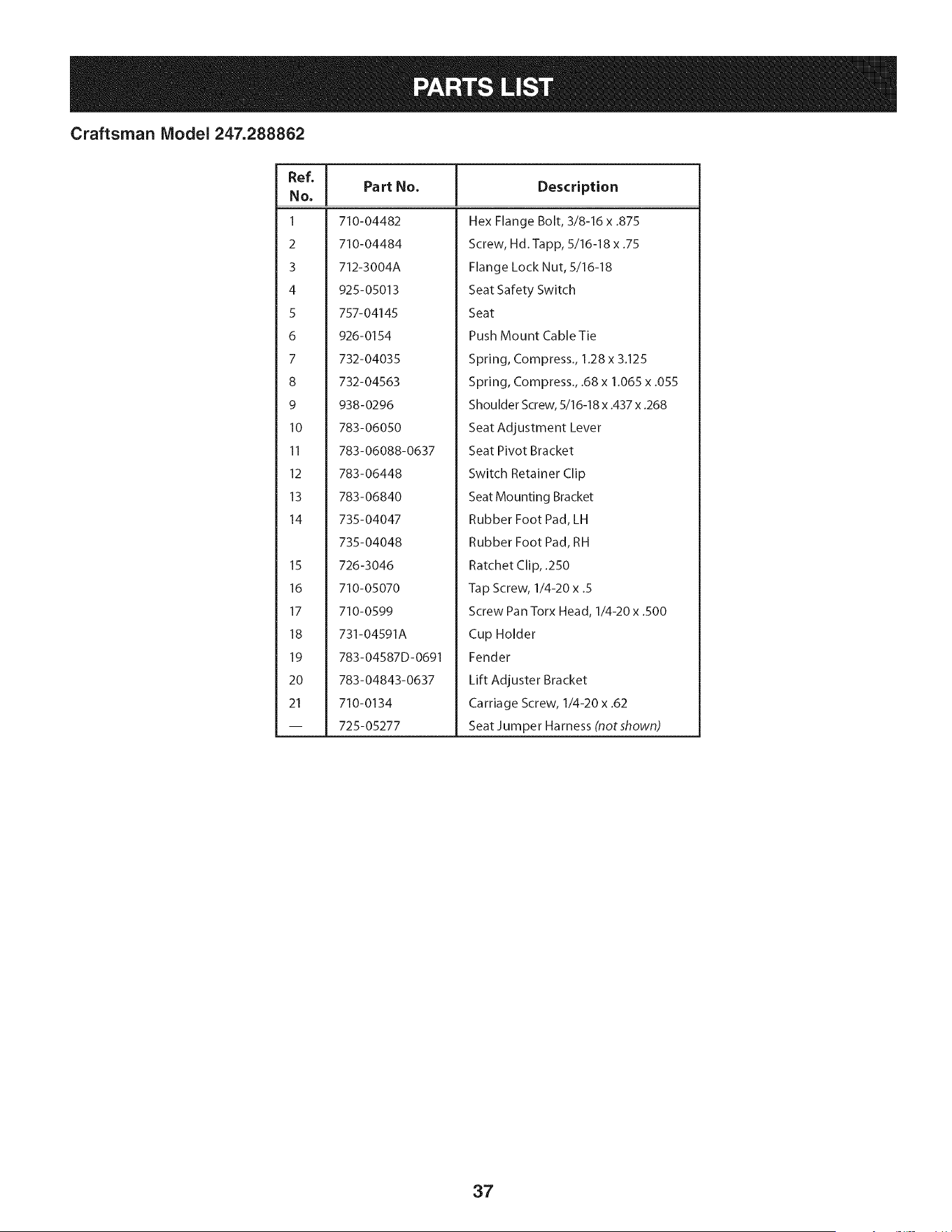
Craftsman Model 247.288862
Ref, [
No,
1 710-04482
2 710-04484
3 712-3004A
4 925-05013
5 757-04145
6 926-0154
7 732-04035
8 732-04563
9 938-0296
10 783-06050
II 783-06088-0637
12 783-06448
13 783-06840
14 735-04047
735-04048
15 726-3046
16 710-05070
17 710-0599
18 731-04591A
19 783-04587D-0691
20 783-04843-0637
21 710-0134
-- 725-05277
Part No, Description
Hex Flange Bolt, 3/8-16 x .875
Screw, Hd. Tapp, 5/16-18 x .75
Flange Lock Nut, 5/16-18
Seat Safety Switch
Seat
Push Mount Cable Tie
Spring, Compress., 1.28 x 3.125
Spring, Compress., .68 x 1.065 x .055
Shoulder Screw, 5/16-18 x .437 x .268
Seat Adjustment Lever
Seat Pivot Bracket
Switch Retainer Clip
Seat Mounting Bracket
Rubber Foot Pad, LH
Rubber Foot Pad, RH
Ratchet Clip, .250
Tap Screw, 1/4-20 x .5
Screw Pan Torx Head, I/4-20x .500
Cup Holder
Fender
Lift Adjuster Bracket
Carriage Screw, 1/4-20 x .62
Seat Jumper Harness (notshown)
37
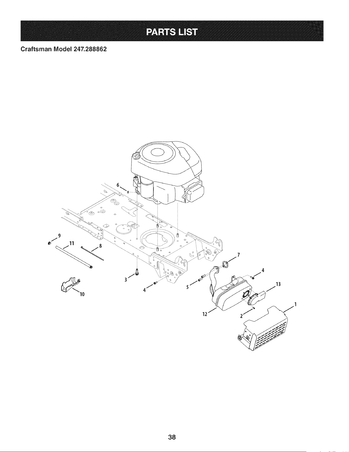
Craftsman IViodel 247.288862
13
38
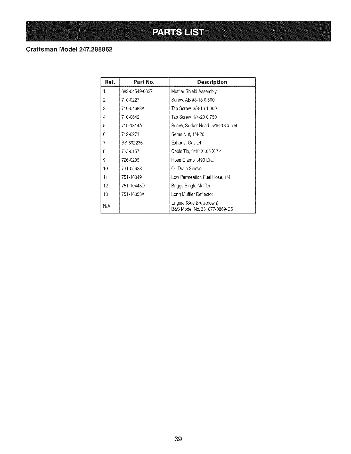
Craftsman IViodel 247.288862
I
Ref.
I Part No.
1 683-04549-0637
2 710-0227
3 710-04683A
4 710-0642
5 710-1314A
6 712-0271
7 BS-692236
8 725-0157
9 726-0205
10 731-05628
11 751-10349
12 751-10448D
13 751-10353A
N/A
Description
MufflerShieldAssembly
Screw,AB #8-180.500
TapScrew,3/8-16 1.000
TapScrew,1/4-200.750
Screw,SocketHead,5/16-18x .750
Sems Nut, 1/4-20
ExhaustGasket
CableTie,3/16 X .05 X 7.4
HoseClamp,.490 Dia.
Oil DrainSleeve
LowPermeationFuelHose,1/4
BriggsSingleMuffler
LongMufflerDeflector
Engine(SeeBreakdown)
B&S ModelNo.331877-0869-G5
39
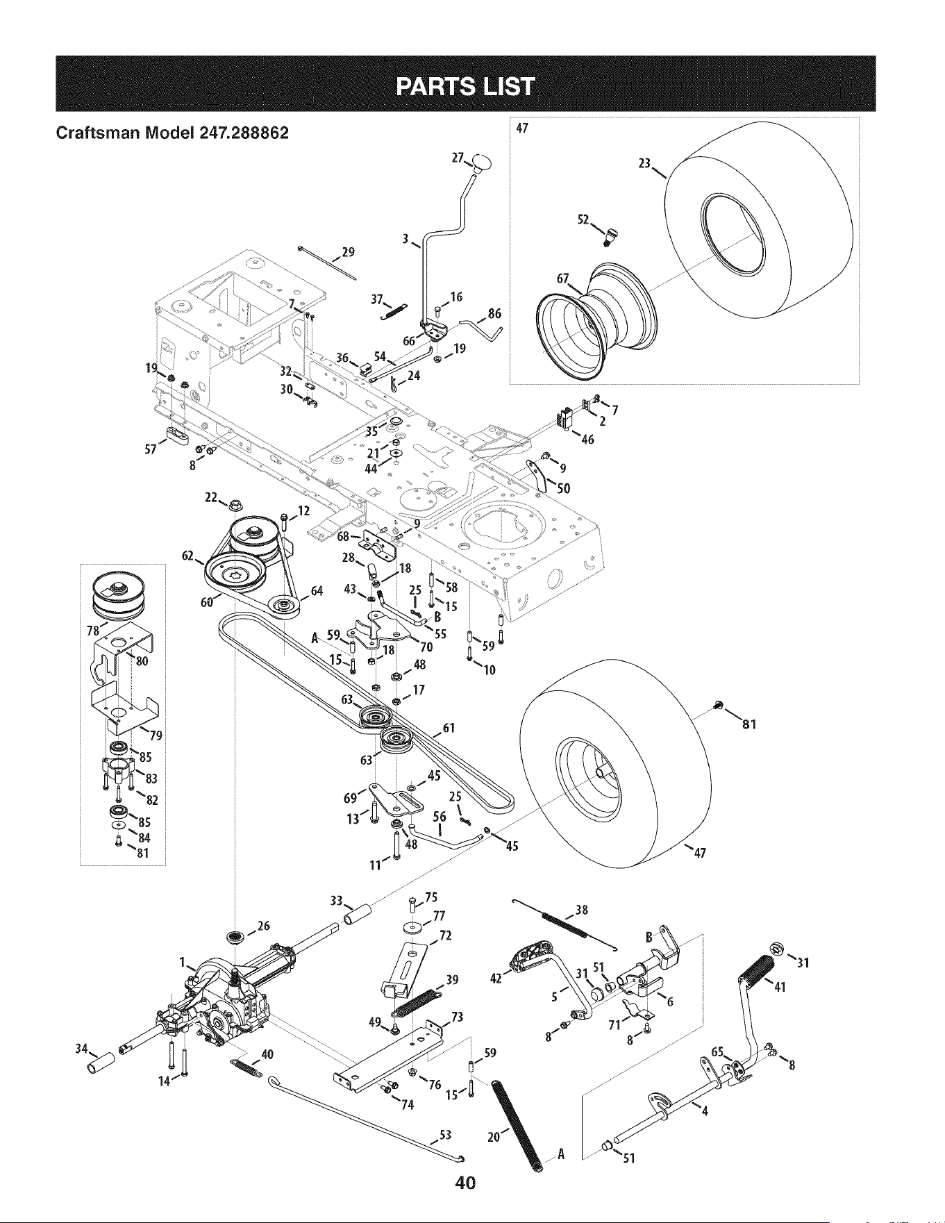
Craftsman Model 247.288862
29
24
47
23\
67
@
'80
61
39 42
73
40
"31
41
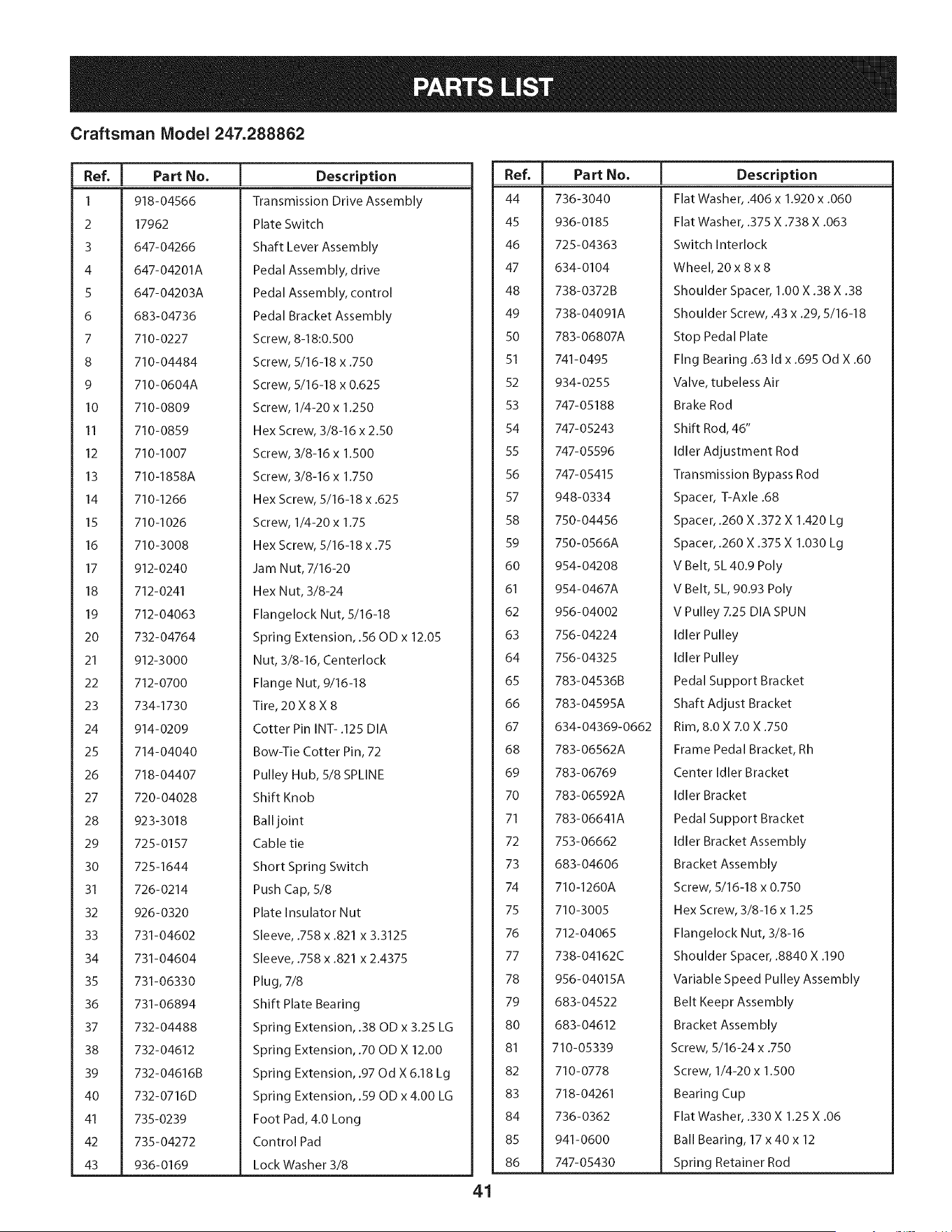
Craftsman Model 247.288862
I
Ref, I Part No.
1 918-04566
2 17962
3 647-04266
4 647-04201A
5 647-04203A
6 683-04736
7 710-0227
8 710-04484
9 710-0604A
10 710-0809
II 710-0859
12 710-I007
13 710-1858A
14 710-1266
15 710-I026
16 710-3008
17 912-0240
18 712-0241
19 712-04063
20 732-04764
21 912-3000
22 712-0700
23 734-1730
24 914-0209
25 714-04040
26 718-04407
27 720-04028
28 923-3018
29 725-0157
30 725-1644
31 726-0214
32 926-0320
33 731-04602
34 731-04604
35 731-06330
36 731-06894
37 732-04488
38 732-04612
39 732-04616B
40 732-0716D
41 735-0239
42 735-04272
43 936-0169
Description
Transmission Drive Assembly
Plate Switch
Shaft Lever Assembly
Pedal Assembly, drive
Pedal Assembly, control
Pedal Bracket Assembly
Screw, 8-18:0.500
Screw, 5/16-18 x .750
Screw, 5/16-18 x 0.625
Screw, 1/4-20 x 1.250
Hex Screw, 3/8-16 x 2.50
Screw, 3/8-16 x 1.500
Screw, 3/8-16 x 1.750
Hex Screw, 5/16-18 x .625
Screw, 1/4-20 x 1.75
Hex Screw, 5/16-18 x .75
Jam Nut, 7/16-20
Hex Nut, 3/8-24
Flangelock Nut, 5/16-18
Spring Extension, .56 OD x 12.05
Nut, 3/8-16, Centerlock
Flange Nut, 9/16-18
Tire, 20X 8 X 8
Cotter Pin INT- .125 DIA
Bow-Tie Cotter Pin, 72
Pulley Hub, 5/8 SPLINE
Shift Knob
Ball joint
Cable tie
Short Spring Switch
Push Cap, 5/8
Plate Insulator Nut
Sleeve, .758 x .821 x 3.3125
Sleeve, .758 x .821 x 2.4375
Plug, 7/8
Shift Plate Bearing
Spring Extension, .38 OD x 3.25 LG
Spring Extension, .70 OD X 12.00
Spring Extension, .97 Od X 6.18 Lg
Spring Extension, .59 OD x 4.00 LG
Foot Pad, 4.0 Long
Control Pad
Lock Washer 3/8
I
Ref, [ Part No,
44 736-3040
45 936-0185
46 725-04363
47 634-0104
48 738-0372B
49 738-04091A
50 783-06807A
51 741-0495
52 934-0255
53 747-05188
54 747-05243
55 747-05596
56 747-05415
57 948-0334
58 750-04456
59 750-0566A
60 954-04208
61 954-0467A
62 956-04002
63 756-04224
64 756-04325
65 783-04536B
66 783-04595A
67 634-04369-0662
68 783-06562A
69 783-06769
70 783-06592A
71 783-06641A
72 753-06662
73 683-04606
74 710-1260A
75 710-3005
76 712-04065
77 738-04162C
78 956-04015A
79 683-04522
80 683-04612
81 710-05339
82 710-0778
83 718-04261
84 736-0362
85 941-0600
86 747-05430
Description
Flat Washer, .406 x 1.920 x .060
Flat Washer, .375 X .738 X .063
Switch Interlock
Wheel, 20x 8x 8
Shoulder Spacer, 1.00 X .38 X .38
Shoulder Screw, .43 x .29, 5/16-18
Stop Pedal Plate
Flng Bearing .63 Id x .695 Od X .60
Valve, tubeless Air
Brake Rod
Shift Rod, 46"
Idler Adjustment Rod
Transmission Bypass Rod
Spacer, T-Axle .68
Spacer, .260 X .372 X 1.420 Lg
Spacer, .260 X .375 X 1.030 Lg
V Belt, 5L 40.9 Poly
V Belt, 5L, 90.93 Poly
V Pulley 7.25 DIA SPUN
Idler Pulley
Idler Pulley
Pedal Support Bracket
Shaft Adjust Bracket
Rim, 8.0 X 7.0 X .750
Frame Pedal Bracket, Rh
Center Idler Bracket
Idler Bracket
Pedal Support Bracket
Idler Bracket Assembly
Bracket Assembly
Screw, 5/16-18 x 0.750
Hex Screw, 3/8-16 x 1.25
Flangelock Nut, 3/8-16
Shoulder Spacer, .8840 X .190
Variable Speed Pulley Assembly
Belt Keepr Assembly
Bracket Assembly
Screw, 5/16-24 x .750
Screw, 1/4-20 x 1.500
Bearing Cup
Flat Washer, .330 X 1.25 X .06
Ball Bearing, 17 x40 x 12
Spring Retainer Rod
41
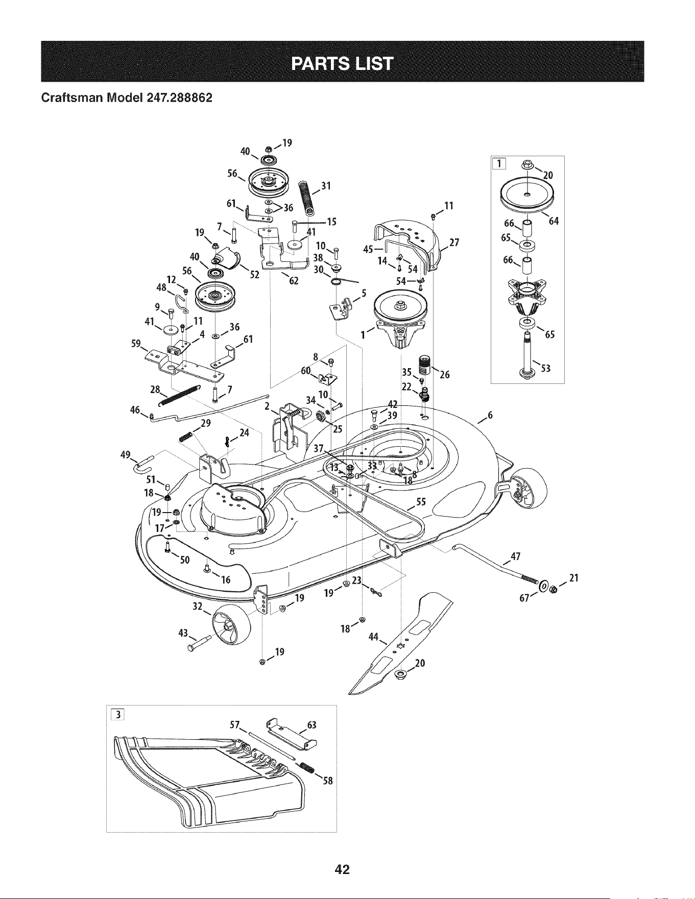
Craftsman Model 247.288862
24 \
27
19
@J
"58
67
42
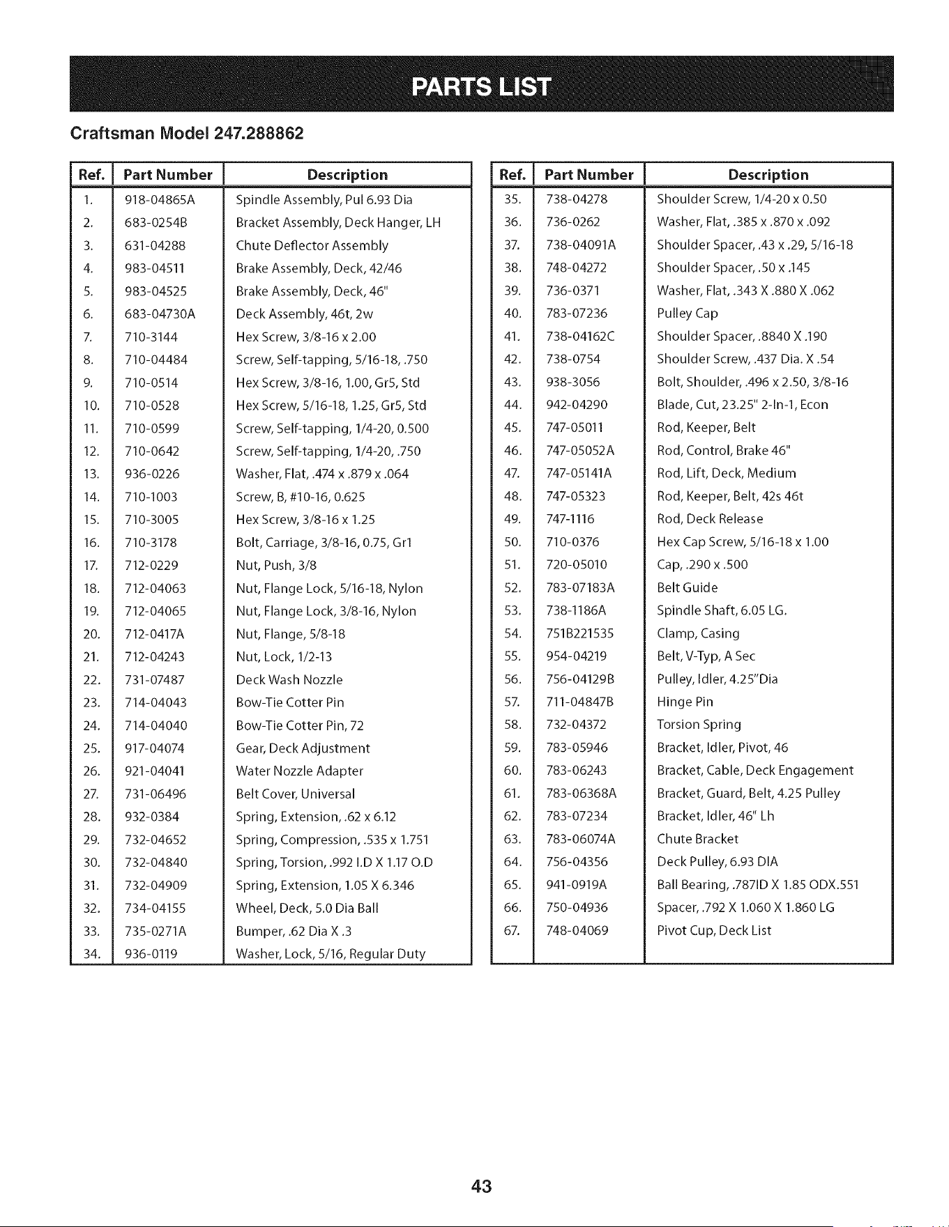
Craftsman Model 247.288862
Ref. I Part Number
1. 918-04865A
2. 683-0254B
3. 631-04288
4. 983-04511
5. 983-04525
6. 683-04730A
7. 710-3144
8. 710-04484
9. 710-0514
10. 710-0528
11. 710-0599
12. 710-0642
13. 936-0226
14. 710-1003
15. 710-3005
16. 710-3178
17. 712-0229
18. 712-04063
19. 712-04065
20. 712-0417A
21. 712-04243
22. 731-07487
23. 714-04043
24. 714-04040
25. 917-04074
26. 921-04041
27. 731-06496
28. 932-0384
29. 732-04652
30. 732-04840
31. 732-04909
32. 734-04155
33. 735-0271A
34. 936-0119
Description
Spindle Assembly, Pul 6.93 Dia
Bracket Assembly, Deck Hanger, LH
Chute Deflector Assembly
Brake Assembly, Deck, 42/46
Brake Assembly, Deck, 46"
Deck Assembly, 46t, 2w
Hex Screw, 3/8-16 x 2.00
Screw, Self-tapping, 5/16-18, .750
Hex Screw, 3/8-16, 1.00, GrS, Std
Hex Screw, 5/16-18, 1.25, GrS, Std
Screw, Self-tapping, 1/4-20, 0.500
Screw, Self-tapping, 1/4-20, .750
Washer, Flat, .474 x .879 x .064
Screw, B, #10-16, 0.625
Hex Screw, 3/8-16 x 1.25
Bolt, Carriage, 3/8-16, 0.75, Grl
Nut, Push, 3/8
Nut, Flange Lock, 5/16-18, Nylon
Nut, Flange Lock, 3/8-16, Nylon
Nut, Flange, 5/8-18
Nut, Lock, 1/2-13
Deck Wash Nozzle
Bow-Tie Cotter Pin
Bow-Tie Cotter Pin, 72
Gear, Deck Adjustment
Water Nozzle Adapter
Belt Cover, Universal
Spring, Extension, .62 x 6.12
Spring, Compression, .535 x 1.751
Spring, Torsion, .992 I.D X 1.17 O.D
Spring, Extension, 1.05 X 6.346
Wheel, Deck, 5.0 Dia Ball
Bumper, .62 Dia X .3
Washer, Lock, 5/16, Regular Duty
Ref. I Part Number
35. 738-04278
36. 736-0262
37. 738-04091A
38. 748-04272
39. 736-0371
40. 783-07236
41. 738-04162C
42. 738-0754
43. 938-3056
44. 942-04290
45. 747-05011
46. 747-05052A
47. 747-05141A
48. 747-05323
49. 747-1116
50. 710-0376
51. 720-05010
52. 783-07183A
53. 738-1186A
54. 751B221535
55. 954-04219
56. 756-04129B
5Z 711-04847B
58. 732-04372
59. 783-05946
60. 783-06243
61. 783-06368A
62. 783-07234
63. 783-06074A
64. 756-04356
65. 941-0919A
66. 750-04936
67. 748-04069
Description
Shoulder Screw, 1/4-20 x 0.50
Washer, Flat, .385 x .870 x .092
Shoulder Spacer, .43 x .29, 5/16-18
Shoulder Spacer, .50 x .145
Washer, Flat, .343 X .880 X .062
Pulley Cap
Shoulder Spacer, .8840 X .190
Shoulder Screw, .437 Dia. X .54
Bolt, Shoulder, .496 x 2.50, 3/8-16
Blade, Cut, 23.25" 2-1n-1, Econ
Rod, Keeper, Belt
Rod, Control, Brake 46"
Rod, Lift, Deck, Medium
Rod, Keeper, Belt, 42s 46t
Rod, Deck Release
Hex Cap Screw, 5/16-18 x 1.00
Cap, .290 x .500
Belt Guide
Spindle Shaft, 6.05 LG.
Clamp, Casing
Belt, V-Typ, A Sec
Pulley, Idler, 4.25"Dia
Hinge Pin
Torsion Spring
Bracket, Idler, Pivot, 46
Bracket, Cable, Deck Engagement
Bracket, Guard, Belt, 4.25 Pulley
Bracket, Idler, 46" Lh
Chute Bracket
Deck Pulley, 6.93 DIA
Ball Bearing, .7871D X 1.85 ODX.551
Spacer, .792 X 1.060 X 1.860 LG
Pivot Cup, Deck List
43
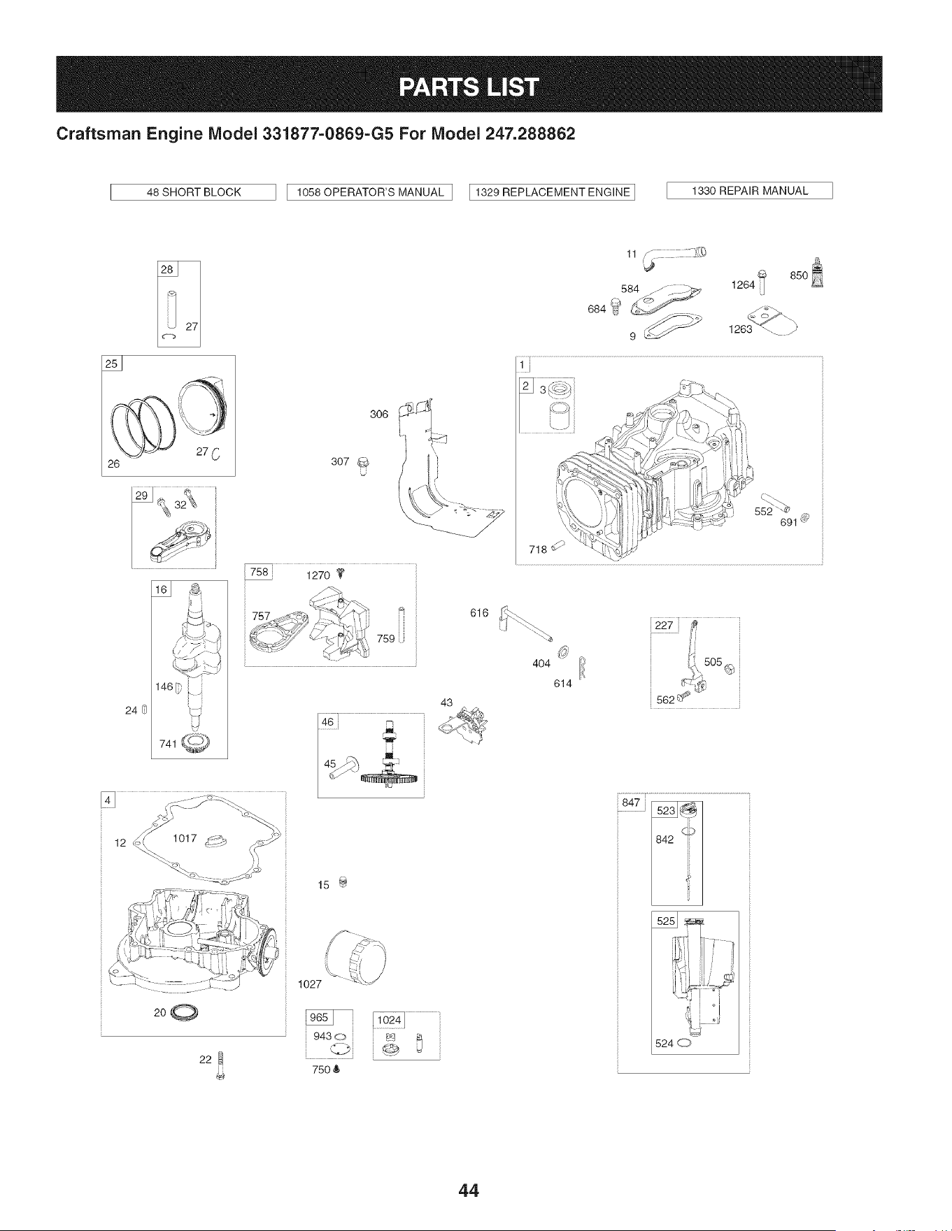
Craftsman Engine IViodel 331877=0869=G5 For IViodel 247.288862
48 SHORT BLOCK
1058 OPERATOR'S MANUAL ] I1329 REPLACEMENT ENGINE ]
1330 REPAIR MANUAL
26
12 1017_i_2__'_ _-'-.__i i
200
22
306
307
U
k _
15 _
1027
75O &
43
616
11 ,_
584 ..-/_. __ 1264
9 _ 1263 _-. y
552 _
691 _
718
404 ion.,505
614 _-,'-_¢,_
562 _ _"
847 _
524 d_7,
44
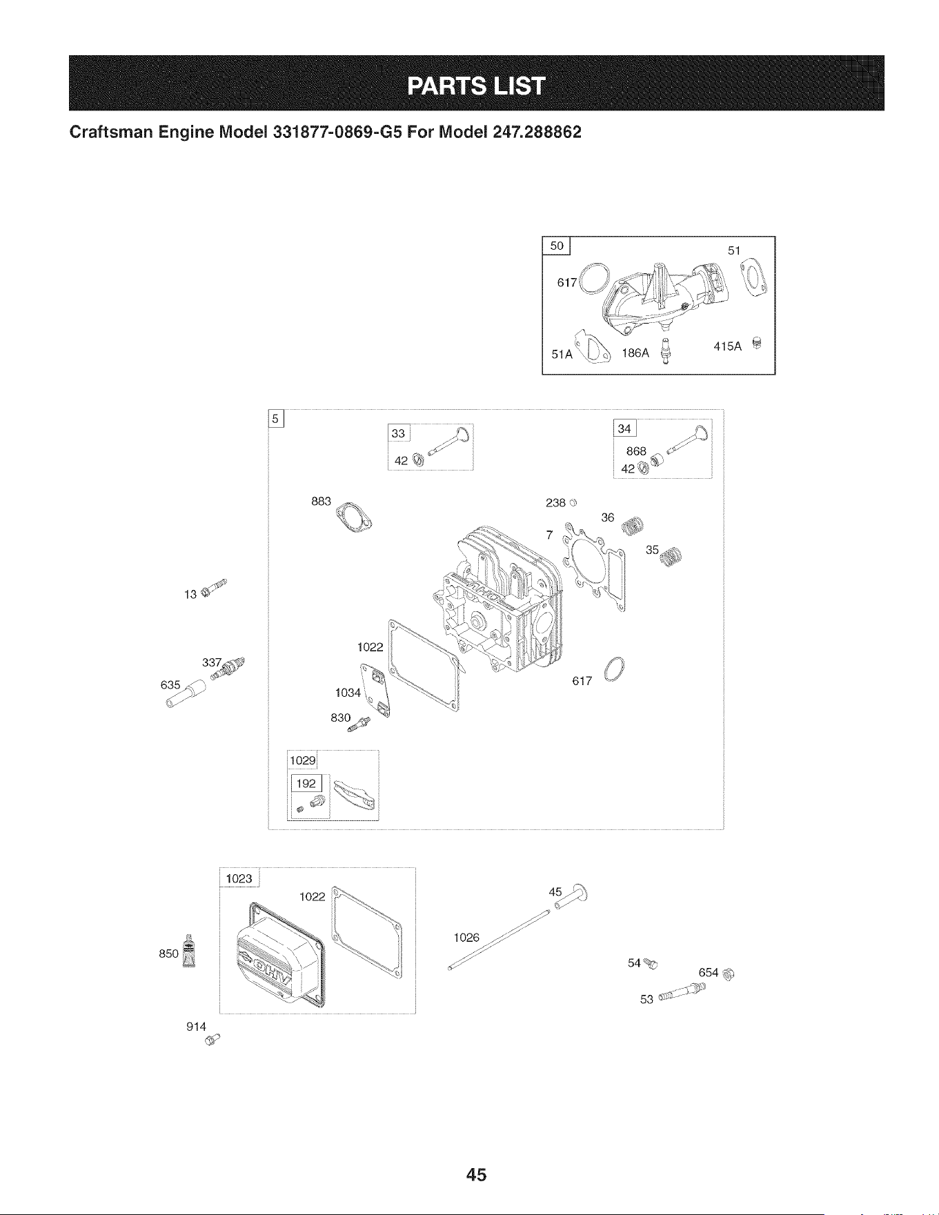
Craftsman Engine Model 331877=0869=G5 For Model 247.288862
5__ 51
51A
186A _ 415A
13_
635_
883
1022
617
i1029}
85O
102
914
1026 _
54%
654 _
53 .......
45
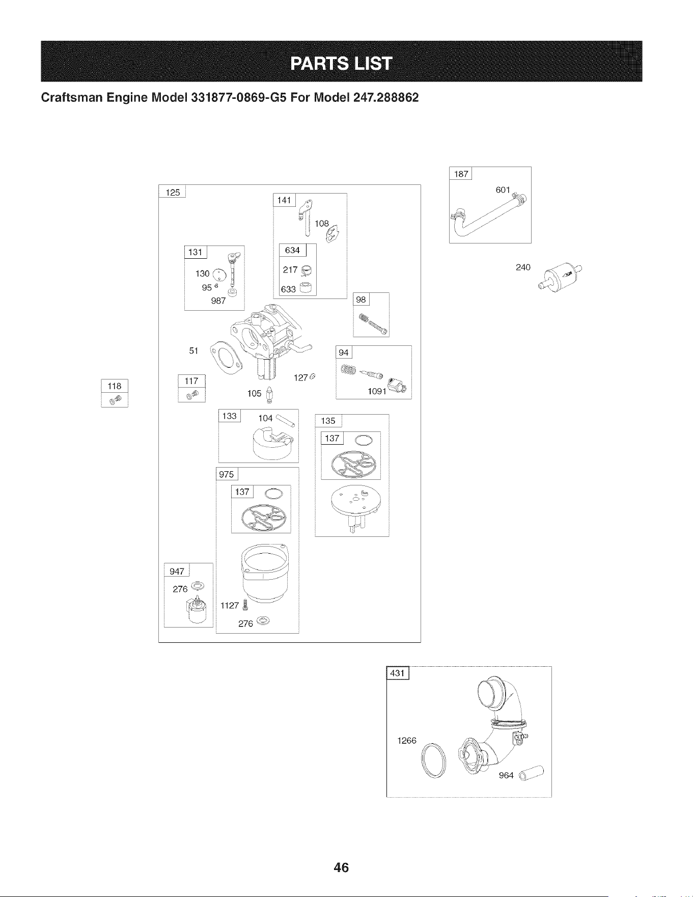
Craftsman Engine IViodel 331877-0869-G5 For IViodel 247.288862
125
13o 1
95 '_ _
987
51
lO2
1270
1091 {{L#
947
276 <_')
_ 1127
_ 276 '-<_
601
24O
1266
46
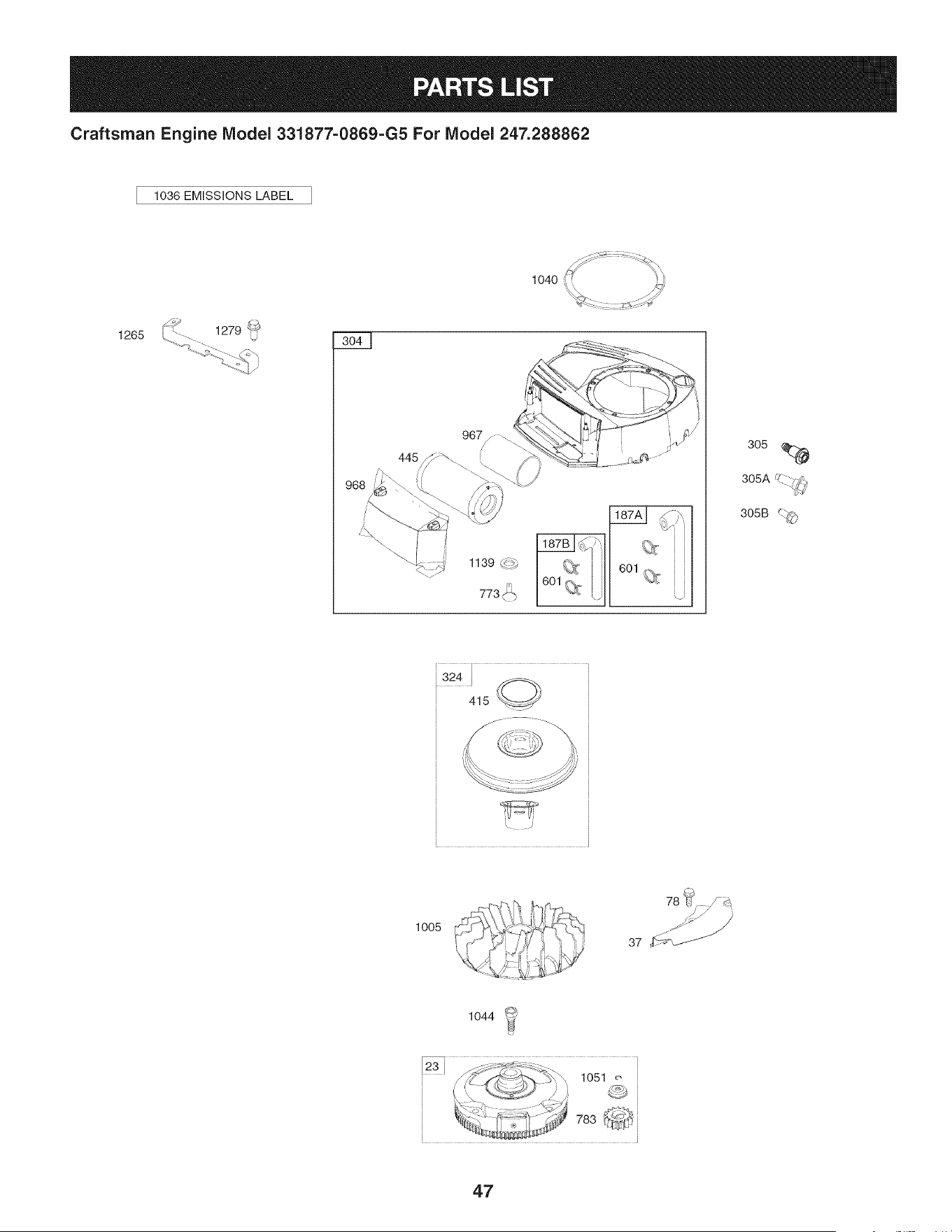
Craftsman Engine IViodel 331877=0869=G5 For IViodel 247.288862
1036 EMiSSiONS LABEL
1265
1139 _._,
305
UZ_--..
305A -.. 7_',
305B _._
,324 i _,
415 _//
:!!!i!!--_
\ .J
1005
78 _¢
37 '_f_
1044
47
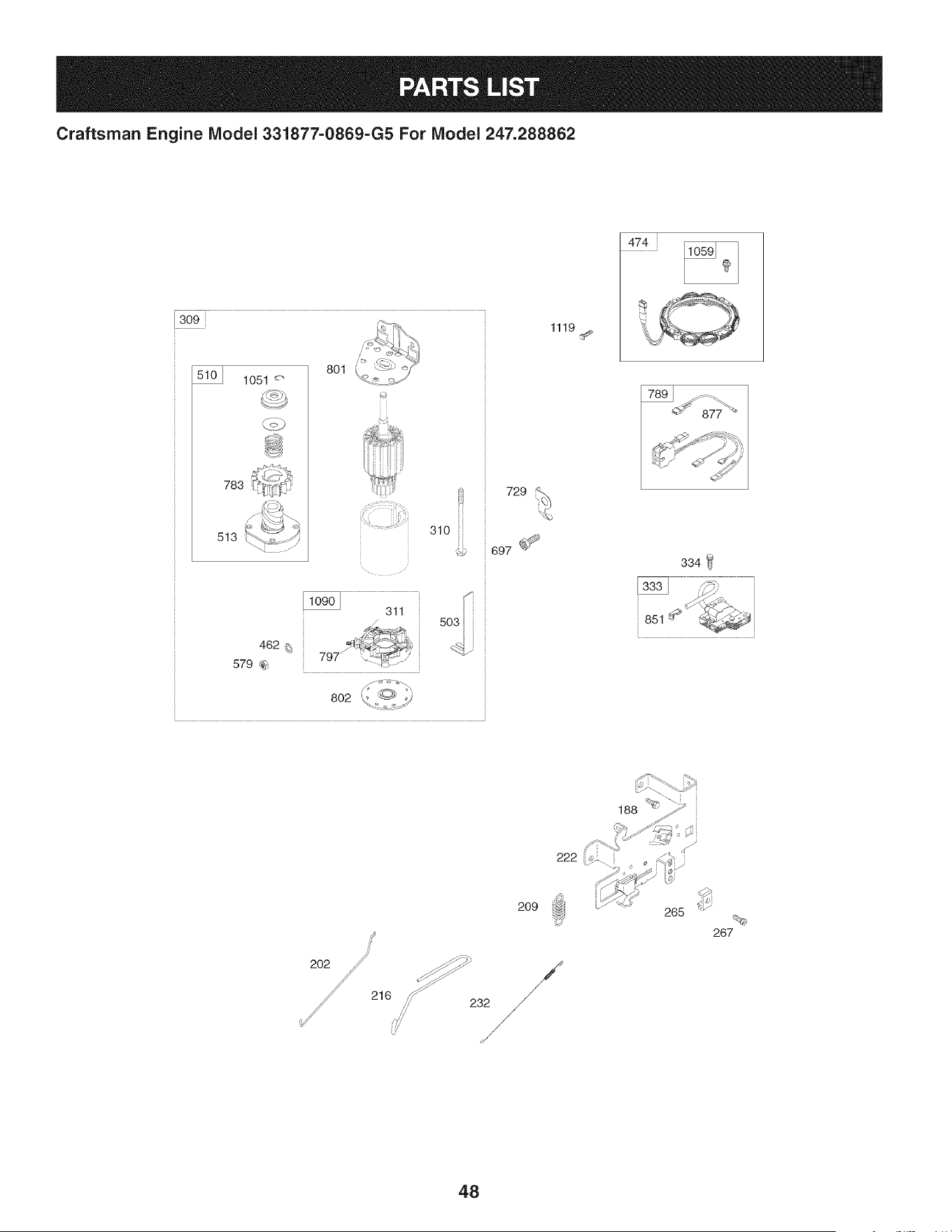
Craftsman Engine IViodel 331877-0869-G5 For IViodel 247.288862
309
1051 <"
783
513
801
310 iii
462 _;
579 _
802
729
697 _
1119
474
334
851
216
2O9
,,,_/ 232
265
267
48
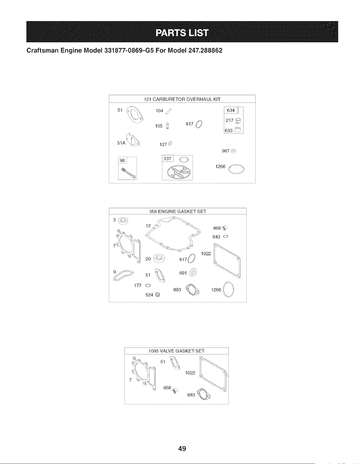
Craftsman Engine Model 331877=0869=G5 For Model 247.288862
51
121 CARBURETOR OVERHAUL KIT
104 _lO50 61__,
127 (_'
987 4_b
, 1266 _ ;_" ;_
ti
/
358 ENGINE GASKET SET
12
1o22
,_
691 _'7//'
1266
1095 VALVE GASKET SET
51
1022
49

Craftsman Engine Model 331877=0869=G5 For Model 247.288862
I
Ref,
I Part No.
No,
I
1 794128
2 399265
3 391086s
4 697188
5 796026
7 794114
9 697109
II 794683
12 697110
13 793988
15 690946
16 797579
20 795387
22 692125
23 698281
24 796335
25 795858
795877
26 794126
794127
27 698469
28 795861
29 794122
32 791118
33 792868
34 791935
35 691279
36 691279
37 699882
42 499586
43 691968
45 690564
46 793880
48 795446
50 796180
51 692137
51A 794312
53 690227
54 691148
78 691693
94 793610
95 690718
Description
Cylinder Assembly
Bushing/Seal Kit (Magneto Side)
Seal-Oil (Magneto Side)
Sump-Engine
Head-Cylinder
Gasket-Cylinder Head
Gasket-Breather
Tube-Breather
Gasket-Crankcase
Screw (Cylinder Head)
Plug-Oil Drain
Crankshaft
Seal-Oil (PTO Side)
Screw (Crankcase Cover/Sump)
Flywheel
Key-Flywheel (Steel)
Piston Assembly (Standard)
Piston Assembly (020" Oversize)
Ring Set (Standard)
Ring Set (.020" Oversize)
Lock-Piston Pin
Pin-Piston
Rod-Connecting
Screw (Connecting Rod)
Valve-Exhaust
Valve-Intake
Spring-Valve (Intake)
Spring-Valve (Exhaust)
Guard-Flywheel
Keeper-Valve
Slinger-Governor/Oil
Tappet-Valve
Camshaft
Short Block
Manifold-Intake
Gasket-Intake
Gasket-Intake
Stud (Carburetor)
Screw (Intake Manifold)
Screw (Flywheel Guard)
Kit-Idle Mixture
Screw (Throttle Valve)
Ref,
No,
98 695408
104 694918
105 696136
108 695419
117 796251
118 791406
121 796184
125 796587
127 690727
130 792747
131 792765
133 694914
135 698780
137 698781
141 792777
146 691639
186 794873
187 791805
187A 791806
187B 791744
188 691693
192 691986
202 691841
209 692208
216 691840
217 695409
222 694042
227 691374
232 691842
238 691843
240 394358s
265 691024
267 794904
276 695410
304 798670
305 697102
305A 793376
305B 795891
306 794953
307 691693
309 693551
I Part No, Description
Kit-Idle Speed
Pin-Float Hinge
Valve-Float Needle
Valve-Choke
Jet-Main (Standard)
Jet-Main (High Altitude)
Kit-Carburetor Overhaul
Carburetor
Plug-Welch
Valve-Throttle
Kit-Throttle Shaft
Float-Carburetor
Tube-Fuel Transfer
Gasket-Float Bowl
Kit-Choke Shaft
Key-Timing
Hose-Connector (Intake Manifold)
Line-Fuel (Formed) (Cut to Length)
Line-Fuel (Formed) (21") (Cut to Length)
Line-Fuel (Formed) (14") (Cut to Length)
Screw (Control Bracket)
Adjuster-Rocker Arm
Link-Mechanical Governor
Spring-Governor (Green)
Link-Choke
Spring-Choke Return
Bracket-Control
Lever-Governor Control
Spring-Governor Link
Cap-Valve
Filter-Fuel
Clamp-Casing
Screw (Casing Clamp)
Washer-Sealing
Housing-Blower
Screw (Blower Housing) (1/4-20x1.14)
Screw (Blower Housing) (1/4-20x.68)
Screw (Blower Housing) (Blower Housing to
Elbow)
Shield-Cylinder
Screw (Cylinder Shield)
Motor-Starter
50
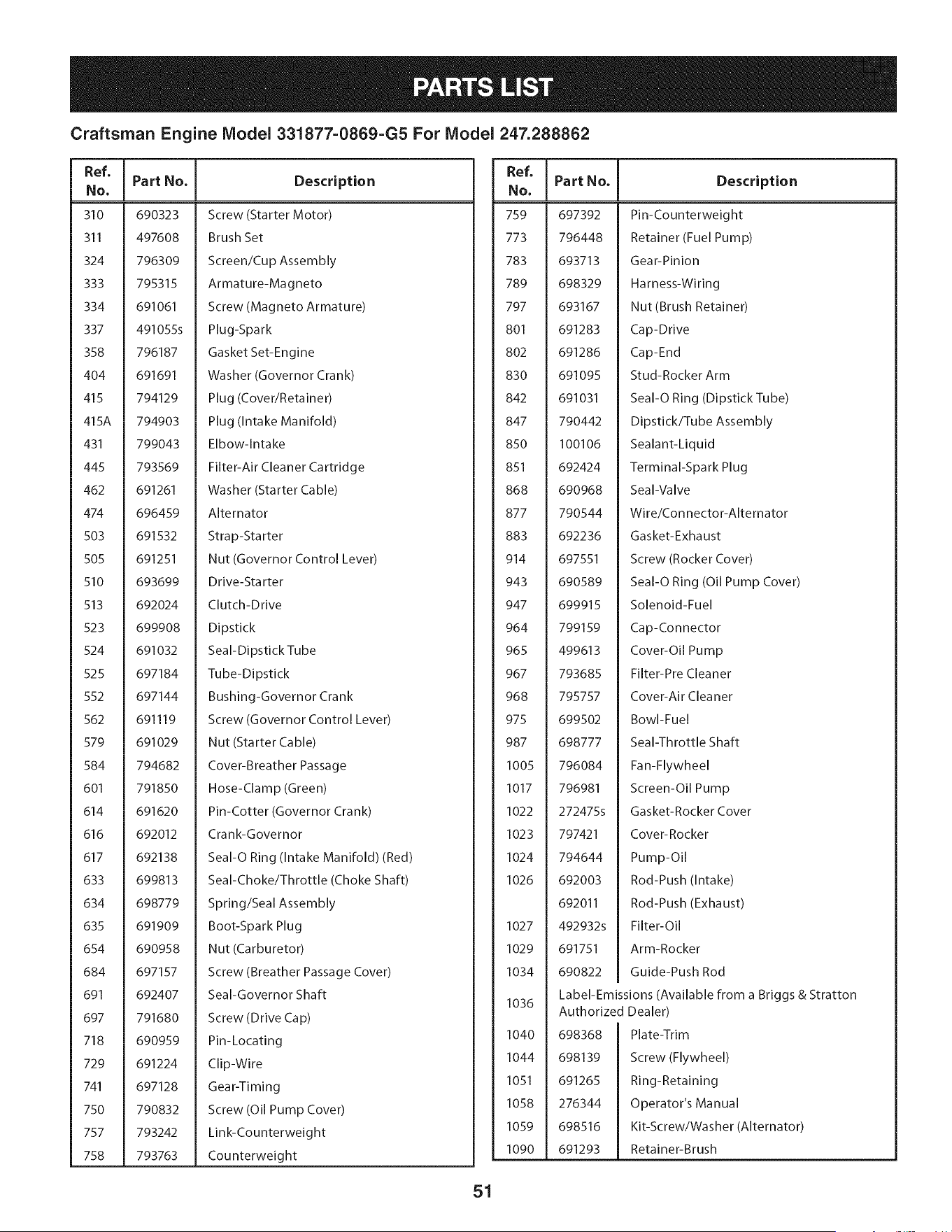
Craftsman Engine Model 331877-0869-G5 For Model 247.288862
I Part No. Description
Ref. Ref.
No. I No.
310 690323
311 497608
324 796309
333 795315
334 691061
337 491055s
358 796187
404 691691
415 794129
415A 794903
431 799043
445 793569
462 691261
474 696459
503 691532
505 691251
510 693699
513 692024
523 699908
524 691032
525 697184
552 697144
562 691119
579 691029
584 794682
601 791850
614 691620
616 692012
617 692138
633 699813
634 698779
635 691909
654 690958
684 697157
691 692407
697 791680
718 690959
729 691224
741 697128
750 790832
757 793242
758 793763
Screw (Starter Motor)
Brush Set
Screen/Cup Assembly
Armature-Magneto
Screw (Magneto Armature)
Plug-Spark
Gasket Set-Engine
Washer (Governor Crank)
Plug (Cover/Retainer)
Plug (Intake Manifold)
Elbow-Intake
Filter-Air Cleaner Cartridge
Washer (Starter Cable)
Alternator
Strap-Starter
Nut (Governor Control Lever)
Drive-Sta rter
Clutch-Drive
Dipstick
Seal-Dipstick Tube
Tube-Dipstick
Bushing-Governor Crank
Screw (Governor Control Lever)
Nut (Starter Cable)
Cover-Breather Passage
Hose-Clamp (Green)
Pin-Cotter (Governor Crank)
Crank-Governor
SeaI-O Ring (Intake Manifold) (Red)
Seal-Choke/Throttle (Choke Shaft)
Spring/Seal Assembly
Boot-Spark Plug
Nut (Carburetor)
Screw (Breather Passage Cover)
Seal-Governor Shaft
Screw (Drive Cap)
Pin-Locating
Clip-Wire
Gear-Timing
Screw (Oil Pump Cover)
Link-Counterweight
Counterweight
Part No.
759 697392
773 796448
783 693713
789 698329
797 693167
801 691283
802 691286
830 691095
842 691031
847 790442
850 100106
851 692424
868 690968
877 790544
883 692236
914 697551
943 690589
947 699915
964 799159
965 499613
967 793685
968 795757
975 699502
987 698777
1005 796084
1017 796981
1022 272475s
1023 797421
1024 794644
1026 692003
692011
1027 492932s
1029 691751
1034 690822
1036
I040
1044
1051
1058
1059
1090
Description
Pin-Counterweight
Retainer (Fuel Pump)
Gear-Pinion
Harness-Wiring
Nut (Brush Retainer)
Cap-Drive
Cap-End
Stud-Rocker Arm
SeaI-O Ring (Dipstick Tube)
Dipstick/Tube Assembly
Sealant-Liquid
Terminal-Spark Plug
Seal-Valve
Wire/Connector-Alternator
Gasket-Exhaust
Screw (Rocker Cover)
SeaI-O Ring (Oil Pump Cover)
Solenoid-Fuel
Cap-Connector
Cover-Oil Pump
Filter-Pre Cleaner
Cover-Air Cleaner
Bowl-Fuel
Seal-Throttle Shaft
Fan-Flywheel
Screen-Oil Pump
Gasket-Rocker Cover
Cover-Rocker
Pump-Oil
Rod-Push (Intake)
Rod-Push (Exhaust)
Filter-Oil
Arm-Rocker
Guide-Push Rod
Label-Emissions (Available from a Briggs & Stratton
Authorized Dealer)
698368
698139
691265
276344
698516
691293
Plate-Trim
Screw (Flywheel)
Ring-Retaining
Operator's Manual
Kit-Screw/Washer (Alternator)
Retainer-Brush
51
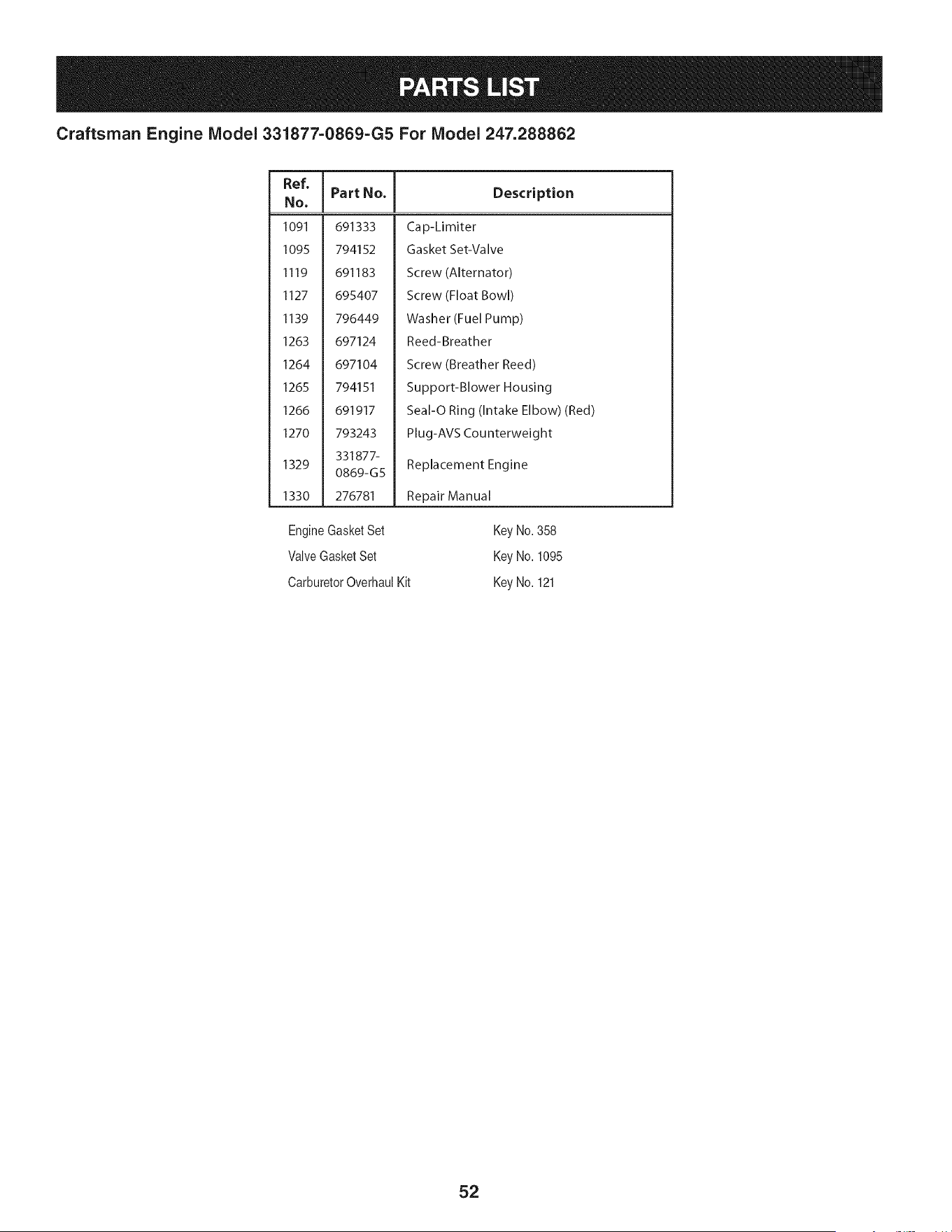
Craftsman Engine Model 331877=0869=G5 For Model 247.288862
Ref,
No.
1091 691333
1095 794152
1119 691183
1127 695407
1139 796449
1263 697124
1264 697104
1265 794151
1266 691917
1270 793243
331877-
1329
0869-G5
1330 276781
I Part No. Description
Cap-Limiter
Gasket Set-Valve
Screw (Alternator)
Screw (Float Bowl)
Washer (Fuel Pump)
Reed-Breather
Screw (Breather Reed)
Support-Blower Housing
Seal-O Ring (Intake Elbow) (Red)
Plug-AVS Counterweight
Replacement Engine
Repair Manual
EngineGasketSet
ValveGasketSet
CarburetorOverhaulKit
Key No.358
Key No.1095
Key No.121
52
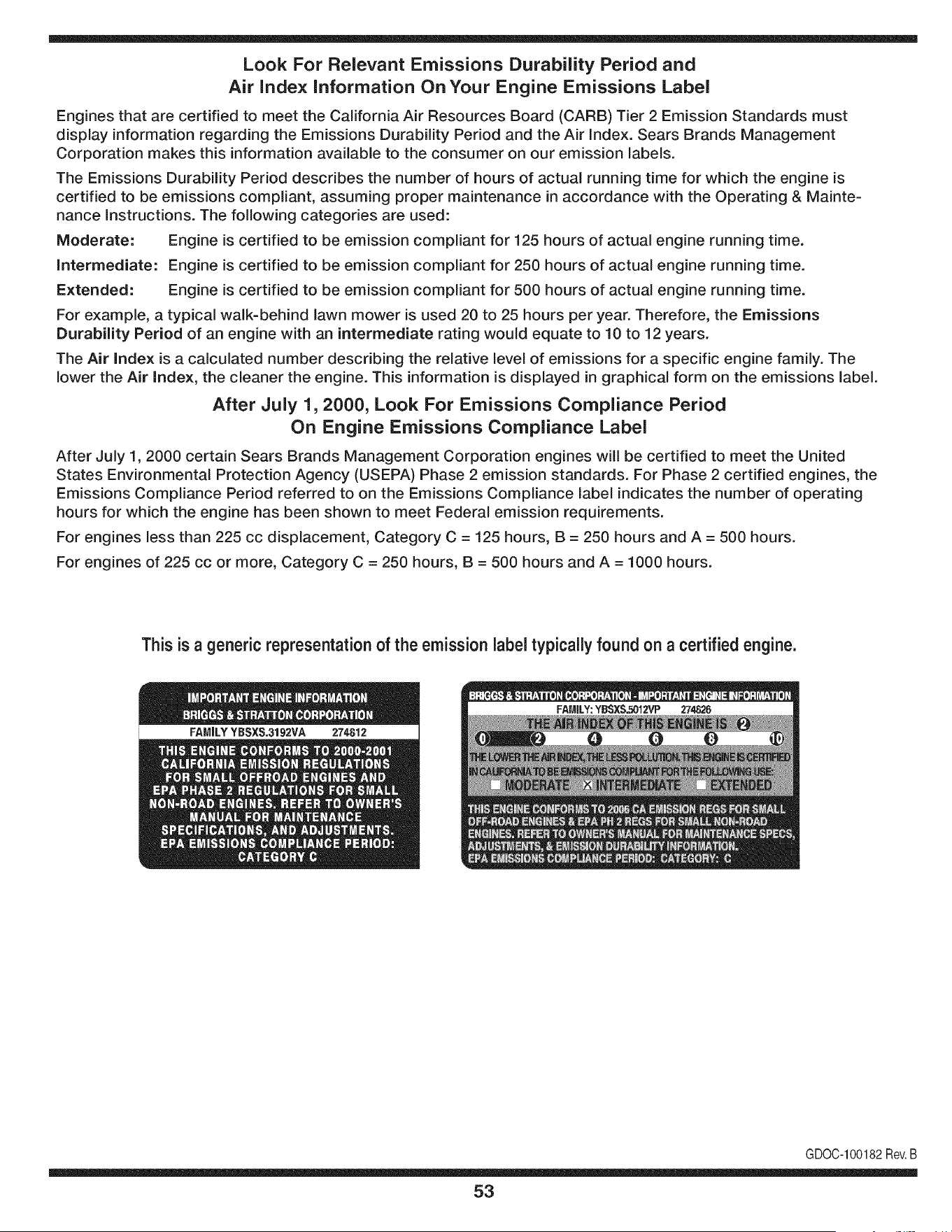
Look For Relevant Emissions Durability Period and
Air index information On Your Engine Emissions Label
Engines that are certified to meet the California Air Resources Board (CARB) Tier 2 Emission Standards must
display information regarding the Emissions Durability Period and the Air Index. Sears Brands Management
Corporation makes this information available to the consumer on our emission labels.
The Emissions Durability Period describes the number of hours of actual running time for which the engine is
certified to be emissions compliant, assuming proper maintenance in accordance with the Operating & Mainte-
nance Instructions. The following categories are used:
Moderate: Engine is certified to be emission compliant for 125 hours of actual engine running time.
Intermediate: Engine is certified to be emission compliant for 250 hours of actual engine running time.
Extended: Engine is certified to be emission compliant for 500 hours of actual engine running time.
For example, a typical walk-behind lawn mower is used 20 to 25 hours per year. Therefore, the Emissions
Durability Period of an engine with an intermediate rating would equate to 10 to 12 years.
The Air index is a calculated number describing the relative level of emissions for a specific engine family. The
lower the Air Index, the cleaner the engine. This information is displayed in graphical form on the emissions label.
After July 1,2000, Look For Emissions Compliance Period
On Engine Emissions Compliance Label
After July 1, 2000 certain Sears Brands Management Corporation engines will be certified to meet the United
States Environmental Protection Agency (USEPA) Phase 2 emission standards. For Phase 2 certified engines, the
Emissions Compliance Period referred to on the Emissions Compliance label indicates the number of operating
hours for which the engine has been shown to meet Federal emission requirements.
For engines less than 225 cc displacement, Category C = 125 hours, B = 250 hours and A = 500 hours.
For engines of 225 cc or more, Category C = 250 hours, B = 500 hours and A = 1000 hours.
This is a generic representation of the emission label typically found on a certified engine.
FAMILYYBSXS.3192VA 274812
GDOC-100182Rev.B
53
(Thispageapplicablein the U.S.A.and Canadaonly.)
Sears Brands Management Corporation (Sears), the California Air Resources Board (CARD)
and the United States Environmental Protection Agency (U.S. EPA)
Emission Control System Warranty Statement (Owner's Defect Warranty Rights and Obligations)
EMISSIONCONTROLWARRANTYCOVERAGEISAPPLICABLETOCERTI-
FIEDENGINESPURCHASEDIN CALIFORNIAIN 1995ANDTHEREAF-
TER,WHICHARE USEDINCALIFORNIA,ANDTO CERTIFIEDMODEL
California and United States Emission
The CaliforniaAir ResourcesBoard(CARD),U.S.EPAand Searsare pleased
to explainthe EmissionControlSystemWarrantyon your modelyear2000and
latersmalloff-roadengine(SORE).In California,newsmall off-roadengines
mustbe designed,builtand equippedto meettheState'sstringentanti-smog
standards.Elsewherein the UnitedStates,newnon-road,spark-ignition
enginescertifiedfor modelyear 1997and latermustmeetsimilarstandardsset
forth bythe U.S.EPA.Sears mustwarranttheemissioncontrol systemonyour
YEAR 1997AND LATERENGINESWHICHARE PURCHASEDAND USED
ELSEWHEREIN THE UNITEDSTATES(ANDAFTERJANUARY1,2001 IN
CANADA).
Control Defects Warranty Statement
enginefor theperiodsoftime listedbelow,providedtherehas been noabuse,
neglector impropermaintenanceof your smalloff-roadengine.Youremis-
sion controlsystemincludespartssuch as thecarburetor,air cleaner,ignition
system,mufflerand catalyticconverter.Also includedmaybe connectorsand
otheremissionrelatedassemblies.Wherea warrantableconditionexists,Sears
will repairyour smalloff-roadengineat no costto you includingdiagnosis,parts
and labor.
Sears Emission Control Defects Warranty Coverage
Smalloff-roadenginesarewarrantedrelativeto emissioncontrolpartsdefects
fora periodof one year,subjectto provisionsset forth below.Ifany covered
Owner's Warranty
Asthe smalloff-roadengine owner,you are responsiblefor the performanceof
therequiredmaintenancelistedin yourOperatingand MaintenanceInstruc-
tions.Searsrecommendsthatyou retain all yourreceiptscoveringmaintenance
on yoursmalloff-roadengine,but Sears cannotdenywarrantysolelyfor the
lackof receiptsorfor yourfailureto ensuretheperformanceof all scheduled
maintenance.As the smalloff-roadengineowner,you shouldhoweverbe
awarethat Searsmay denyyou warrantycoverageif your smalloff-roadengine
ora part hasfailed dueto abuse,neglect,impropermaintenanceor unap-
parton yourengineis defective,the part will be repairedorreplacedbySears.
Responsibilities
provedmodifications.Youare responsiblefor presentingyour smalloff-road
engineto an AuthorizedSearsServiceDealeras soonas a problemexists.The
undisputedwarrantyrepairsshouldbe completedina reasonableamountof
time,notto exceed30 days.Ifyou haveany questionsregardingyourwarranty
rightsand responsibilities,youshouldcontacta SearsService Representative
at 1-800-469-4663.The emissionwarrantyis a defectswarranty.Defectsare
judgedon normalengineperformance.The warrantyis notrelatedto an in-use
emissiontest.
Sears Emission Control Defects Warranty Provisions
ThefollowingarespecificprovisionsrelativetoyourEmissionControlDefectsWarrantyCoverage.Itisin additiontotheSearsenginewarrantyfornon-regulated
enginesfound in the Operatingand MaintenanceInstructions.
1. WarrantedParts
Coverageunderthis warrantyextendsonly to the parts listedbelow (the
emissioncontrolsystemsparts)to the extentthese partswere presenton
theengine purchased.
a. FuelMeteringSystem
• Cold start enrichmentsystem
• Carburetorand internalparts
• FuelPump
b. Air lnduction System
• Air cleaner
• Intakemanifold
c. IgnitionSystem
• Spark plug(s)
• Magnetoignitionsystem
d. CatalystSystem
• Catalyticconverter
• Exhaustmanifold
• Air injectionsystemor pulsevalve
e. MiscellaneousItemsUsedin AboveSystems
• Vacuum,temperature,position,timesensitivevalves
andswitches
• Connectorsandassemblies
2. Lengthof Coverage
Searswarrantsto the initialownerand eachsubsequentpurchaserthat
theWarrantedPartsshallbefree from defects in materialsandworkman-
shipwhich causedthe failure of the WarrantedPartsfor a periodof one
yearfrom the datethe engineis deliveredto a retailpurchaser.
3. NoCharge
Repairor replacementof anyWarrantedPartwill beperformedat no
chargeto the owner,includingdiagnosticlabor whichleadsto the
determinationthata WarrantedPartis defective,if the diagnosticwork is
performedat an AuthorizedSears ServiceDealer.Foremissionswarranty
servicecontact yournearestAuthorizedSears ServiceDealeras listed in
the "YellowPages"under"Engines,Gasoline,""GasolineEngines,""Lawn
Mowers,"orsimilar category.
4. Claimsand CoverageExclusions
Warrantyclaimsshall be filed in accordancewiththe provisionsof the
Sears EngineWarrantyPolicy.Warrantycoverageshall be excludedfor
failuresof WarrantedPartswhichare not original Sears partsor because
of abuse, neglector impropermaintenanceas setforth inthe Sears
EngineWarrantyPolicy.Searsis not liableto coverfailuresof Warranted
Partscausedby the use of add-on, non-original,or modifiedparts.
5. Maintenance
Any WarrantedPart whichis notscheduledfor replacementas required
maintenanceor whichis scheduledonly for regularinspectionto the effect
of "repairor replaceas necessary"shallbe warrantedas to defectsfor the
warrantyperiod.Any WarrantedPartwhich is scheduledfor replacement
as requiredmaintenanceshallbe warrantedas to defectsonly forthe
periodof time upto the firstscheduledreplacementfor that part. Any
replacementpart that is equivalentin performanceand durabilitymay
be usedin the performanceof any maintenanceor repairs.The owneris
responsibleforthe performanceof all requiredmaintenance,as definedin
the SearsOperatingand MaintenanceInstructions.
6. ConsequentialCoverage
Coveragehereundershallextendto thefailure of any engine components
caused bythe failureof any WarrantedPartstill underwarranty.
Inthe USAandCanada,a 24 hour hot line, 1-800-469-4663,has a menu of pre-recordedmessagesofferingyou enginemaintenanceinformation.
GDOC-100188Rev.B
54
FEDERALand/or CALIFORNIAEMISSIONCONTROLWARRANTYSTATEMENT
YOURWARRANTYRIGHTSANDOBLIGATIONS
MTD Consumer Group Inc, the United States Environmental Protection Agency (EPA), and, for those products certified for sale in the state of
California, the California Air Resources Board (CARB) are pleased to explain the emission (evaporative and/or exhaust) control system (ECS)
warranty on your outdoor 2006 and later small off-road spark-ignited engine and equipment (outdoor equipment engine) In California, new
outdoor equipment engines must be designed, built and equipped to meet the State's stringent anti-smog standards (in other states, 1997 and
later model year equipment must be designed, built, and equipped to meet the U.S. EPA small off-road, spark ignition engine regulations. MTD
Consumer Group Inc must warrant the ECSon your outdoor equipment engine for the period of time listed below provided there has been no
abuse, neglect or improper maintenance of outdoor equipment engine.
Your ECS may include parts such as the carburetor, fuel-injection system, the ignition system, catalytic converter, fuel tanks, fuel lines, fuel caps,
valves, canisters, filters, vapor hoses, clamps, connectors, and other associated emission-related components.
Where a warrantable condition exists, MTD Consumer Group Inc will repair your outdoor equipment engine at no cost to you including
diagnosis, parts and labor.
MANUFACTURER'SWARRANTYCOVERAGE:
This emission control system is warranted for two years. If any emission-related part on your outdoor equipment engine is defective, the part
will be repaired or replaced by MTD CONSUMER GROUP INC.
OWNER'SWARRANTYRESPONSIBILITIES:
As the outdoor equipment engine owner, you are responsible for performance of the required maintenance listed in your owner's manual. MTD
Consumer Group Inc recommends that you retain all receipts covering maintenance on your outdoor equipment engine, but MTD Consumer
Group Inc cannot deny warranty solely for the lack of receipts.
As the outdoor equipment engine owner, you should however be aware that MTD Consumer Group Inc may deny you warranty coverage if
your outdoor equipment engine or a part has failed due to abuse, neglect, or improper maintenance or unapproved modifications.
You are responsible for presenting your outdoor equipment engine to MTD Consumer Group Inc's distribution center or service center as soon
as the problem exists. The warranty repairs should be completed in a reasonable amount of time, not to exceed 30 days. If you have a question
regarding your warranty coverage, you should contact the MTD Consumer Group Inc Service Department at 1-800-800-7310 or via email at
http://su pport.mtd prod ucts.com
GENERALEMISSIONSWARRANTYCOVERAGE:
MTD Consumer Group Inc warrants to the ultimate purchaser and each subsequent purchaser that the outdoor equipment engine is: Designed,
built and equipped so as to conform with all applicable regulations; and free from defects in materials and workmanship that cause the failure
of a warranted part to be identical in all material respects to that part as described in MTD Consumer Group Inc's application for certification.
The warranty period begins on the date the outdoor equipment engine is delivered to an ultimate purchaser or first placed into service. The
warranty period is two years.
Subject to certain conditions and exclusions as stated below, the warranty on emission-related parts is as follows:
1. Any warranted part that is not scheduled for replacement as required maintenance in the written instructions supplied, is warranted for
the warranty period stated above. If the part fails during the period of warranty coverage, the part will be repaired or replaced by MTD
Consumer Group Inc according to subsection (4) below. Any such part repaired or replaced under warranty will be warranted for the
remainder of the period.
2. Any warranted part that is scheduled only for regular inspection in the written instructions supplied is warranted for the warranty period
stated above. Any such part repaired or replaced under warranty will be warranted for the remaining warranty period.
3. Any warranted part that is scheduled for replacement as required maintenance in the written instructions supplied is warranted for the
period of time before the first scheduled replacement date for that part. If the part fails before the first scheduled replacement, the part
will be repaired or replaced by MTD Consumer Group Inc according to subsection (4) below. Any such part repaired or replaced under
warranty will be warranted for the remainder of the period prior to the first scheduled replacement point for the part.
Repair or replacement of any warranted part under the warranty provisions herein must be performed at a warranty station at no charge
to the owner.
4.
5. Notwithstanding the provisions herein, warranty services or repairs will be provided at all of our distribution centers that are franchised to
service the subject engines or equipment.
6. The outdoor equipment engine owner will not be charged for diagnostic labor that is directly associated with diagnosis of a defective,
emission-related warranted part, provided that such diagnostic work is performed at a warranty station.
7. MTD Consumer Group Inc is liable for damages to other engine or equipment components proximately caused by a failure under
warranty of any warranted part.
8. Throughout the off-road engine and equipment warranty period stated above, MTD Consumer Group Inc will maintain a supply of
warranted parts sufficient to meet the expected demand for such parts.
9. Any replacement part may be used in the performance of any warranty maintenance or repairs and must be provided without charge to
the owner. Such use will not reduce the warranty obligations of MTD Consumer Group Inc.
10. Add-onormodifiedpartsthatarenotexemptedbytheAirResourcesBoardmaynotbeused.Theuseofanynon-exemptedadd-onor
modifiedpartsbytheultimatepurchaserwillbegroundsfordisallowingawarrantyclaims.MTDConsumerGroupIncwillnotbeliableto
warrantfailuresofwarrantedpartscausedbytheuseofanon-exemptedadd-onormodifiedpart.
WARRANTEDPARTS:
The repair or replacement of any warranted part otherwise eligible for warranty coverage may be excluded from such warranty coverage if
MTD Consumer Group Inc demonstrates that the outdoor equipment engine has been abused, neglected, or improperly maintained, and that
such abuse, neglect, or improper maintenance was the direct cause of the need for repair or replacement of the part. That notwithstanding,
any adjustment of a component that has a factory installed, and properly operating, adjustment limiting device is still eligible for warranty
coverage. Further, the coverage under this warranty extends only to parts that were present on the off-road engine and equipment purchased.
The following emission warranty parts are covered (if applicable):
1. Fuel Metering System
Cold start enrichment system (soft choke)
Carburetor and internal parts (or fuel injection system)
Fuel pump
Fuel tank
2. Air Induction System
Air cleaner
Intake manifold
3. Ignition System
Spark plug(s)
Magneto ignition system
4. Exhaust System
Cata lytic converter
SAI (Reed valve)
5. Miscellaneous Items Used in Above System
Vacuum, temperature, position, time sensitive valves and switches
Connectors and assemblies
6. Evaporative Control
Fuel hose
Fuel hose clamps
Tethered fuel cap
Carbon canister
• Vapor lines
GDOCq00223Rev.A

Congratulations on making a smart purchase. Your new Craftsman® product is designed and
manufactured for years of dependable operation. But like all products, it may require repair
from time to time. That's when having a Repair Protection Agreement can save you money and
aggravation.
Here's what the Repair Protection Agreement* includes:
[] Expert service by our 10,000 professional repair specialists
[] Unlimited service and no charge for parts and labor on all covered repairs
[] Product replacement up to $1500 if your covered product can't be fixed
[] Discount of 25% from regular price of service and related installed parts not covered by the
agreement; also, 25% off regular price of preventive maintenance check
[] Fast help by phone - we call it Rapid Resolution - phone support from a Sears representative.
Think of us as a "talking owner's manual."
Once you purchase the Repair Protection Agreement, a simple phone call is all that it takes for you
to schedule service. You can call anytime day or night, or schedule a service appointment online.
The Repair Protection Agreement is a risk-free purchase. If you cancel for any reason during the
product warranty period, we will provide a full refund. Or, a prorated refund anytime after the
product warranty period expires. Purchase your Repair Protection Agreement today!
Some limitations and exclusions apply. For prices and additional information in the U.S.A.
call 1=800=827=6655.
*Coverage in Canada varies on some items. For full details call Sears Canada at 1=800=361=
6665.
Sears Installation Service
For Sears professional installation of home appliances, garage door openers, water heaters, and
other major home items, in the U.S.A. or Canada call 1=800=4=MY=HOME®.
57
Operaci6n segura Practicas .......... Paginas 59 Fuera de temporada de almacenamiento .. Page 85
Etiquetas De Seguridad ................ Page 65 Soluci6n de problemas ................ Page 86
Asamblea ........................... Page 66 Lista de piezas ..................... Paginas 30
Operacion de ...................... Paginas 68 Reparaci6n de Acuerdo de Protecci6n .... Page 91
De Servicio y Mantenimiento de ....... Paginas 75 Servicio de nOmeros ............ atrasados Page
CRAFTSMAN GARANT{A COMPLETA
DURANTEdosa_osdesdela fechadecompra,todaslaspartesde nofungiblesdeesteequipodeequitaci6nestangarantizadascontracualquier
defectode materialo manode obra.Unaparteno fungiblesdefectuosarecibirAa domicilioreparaci6no la sustituci6nsila reparaci6nnoestAdisponible.
GARANT{ALIMITADADE LABATER{A
POR90 diasdesde lafechade compra,la bateria(unapiezaconsumible)de este equipode conducci6nesta garantizadacontra cualquier
defectode materialo manodeobra. Unabaterianuevase suministrar_gratuitamente.Ustedes responsableporelcostode manodeobra de
instalaci6nde la bateria.
GARANT{ALIMITADAADICIONAL
Enlas siguientesgaranfiasadicionales,ustedes responsablepor el costodemanode obrade instalaci6nde la partedespu_sdel segundoaSo
desdela fecha de compra.
DURANTEcincoaSosdesdela fecha de compra,el marcodeeste equipode conducci6nest&garantizadocontra cualquierdefectode material
o manode obra.Se suministrarAun nuevomarcodeforma gratuita.
DURANTEdiezaSosdesde lafechadecompra,el ejedelanterodeesteequipode conducci6nest&garantizadocontracualquierdefectode
materialo manodeobra. Sesuministrar&un nuevoeje delanterogratuitamente.
PARAmientrases utilizadopor el propietariooriginaldespu_sdel d_cimoaSode lafechadecompra,el eje hierrofundidofrontal (si esta
equipado)de esteequipodeconducci6nest&garantizadocontracualquierdefectode materialo manode obra.Concomprobantede compra,
se suministrar&un nuevoeje delanterode fundici6nde hierrodeformagratuita.
SERVICIODEGARANT{A
Paradetallesde lacoberturade garanfiaobtenerla reparaci6no reemplazo,Ilameal 1-800-659-5917o visite elsitioweb:www.craftsman.com
Entodosloscasos,sisepartedela reparaci6no reemplazoesimposible,el equipode equitaci6nsereemplazar&gratuitamenteconelmismooequivalente.
Todoslosdelaanteriorgarantiaesnulasiseutilizaesteequipodeconducci6nmientrasqueproporcionaservicioscomercialeso Sialquilaa otrapersona.
Estagaranfiacubresolamentedefectosenmaterialy manode obra. Coberturade la garanfianoincluye:
• Piezasfungibles(exceptola bateria)que puedengastarsepor el uso normaldentrodel periodode garanfia,incluyendoperono limitadoa
cuchillas,bujias, filtrosde aire,correasy filtros de aceite.
• Serviciode mantenimientoestandar,cambiosde aceiteo puestasa punto.
• NeumAticode repuestoo reparaci6ncausadaspor pinchazosde objetosexternos,talescomoclavos,espinas,toconeso vidrio.
NeumAticoo ruedade repuestoo reparaci6nresultantesdel desgastenormal,accidente,o funcionamientoincorrectoomantenimiento.
• Reparacionesnecesariasdebidoa abusodel operador,incluyendoperonolimitadoa daSoscausadosporobjetosm&saliade la capacidad
de losequiposde conducci6nde remolque,afectarobjetosquedoblanel marco,el eje o el cig(JeSalo over-speedingel motor.
• Reparacionesnecesariasdebidoa la negligenciadeloperador,incluyendopero no limitadoa, daSosel_ctricosy mecanicoscausados
poralmacenamientoinadecuado,no usarelgradoadecuadoy la cantidadde aceitede motor,nomantenerla cubiertalibre de residuos
inflamables,o faltade mantenimientodel equipode equitaci6nsegQnlas instruccionescontenidasen el manualdel operador.
Motor(sistemadecombustible)limpiezao reparacionesocasionadosporel combustibledeterminadoestarcontaminadosuoxidan
(obsoletos).En general,el combustibledebeutilizarsedentrode30 diasde la fechade compra.
• Eldeterioronormaly el desgastedelos acabadosexteriores,o reemplazode la etiquetadel producto.
Estagarantiale otorgaderechoslegalesespedficos,y ustedtambi_npuedetenerotrosderechosquevariande estadoa estado.
Sears Brands Management Cm )oration, Hoffman Estates, IL 60179
Aceitedel motor: SAE30 NSrnerode modelo ..........................................................
Combustible: Gasolinasinplomo N_mero de serie ..............................................................
Bujia: Champion®RC12YC Fechade compra .............................................................
Motor: Briggs& Stratton RegistrearribaelnOmerodelmodelo,elnOmerodeserieylafechadecompra
© Sears Brands,LLC 58
Lapresenciadeeste sirnboloindicaque setratade instrucciones
irnportantesde seguridadquese deben respetarparaevitar
poneren peligrosu seguridadpersonaly/o materialy la de otras
personas.Leay siga todaslas instruccionesdeestemanualantes
de poneren funcionarnientoestarn_.quina.Si no respetaestas
instruccionespodriaprovocarlesionespersonales.Cuandoveaeste
sirnbolo,ipresteatenci6na la advertencia!
PROPOSICI(])N 65 DE CALIFORNIA
Elescapedel motordeeste producto,algunosde suscornponentes
y algunoscornponentesdelvehiculocontieneno liberan sustancias
quirnicasqueel estado de Californiaconsideraque puedenproducir
c_.ncer,defectosde nacirnientou otros problernasreproductivos.
Losbornesdela bateriay los accesoriosalinescontienenplornoy
cornpuestosde plorno,sustanciasquirnicasque segOnIo estableci-
do pot el Estadode Californiacausanc_.ncery da_osenel sisterna
reproductivo.Ldveselas manos despu_sde estaren contacto
con estoscomponentes.
Estarn_.quinarue construidapara seroperadadeacuerdocon
las reglasde seguridadcontenidasen este manual.AI igualque
concualquiertipo deequipornotorizado,undescuidoo errorpor
partedel operadorpuedeproducirlesionesgraves.Estarn_.quina
es capazde arnputarrnanosy piesy dearrojarobjetoscon gran
fuerza.Deno respetarlas instruccionesde seguridadsiguientesse
puedenproducirlesionesgraveso larnuerte.
Su responsabilidad--Restrinja el usode esta rn_.quina
rnotorizadaalas personasque lean,cornprendany respetenlas
advertenciase instruccionesque aparecenen este manualyen la
rn_.quina.
iGUARDEESTASINSTRUCCIONES!
FUNCIONAMIENTO GENERAL
• Lea,entienday curnplatodaslas instruccionesincluidasen
la rn_.quinayen los rnanualesantesdernontarlay utilizarla.
Guardeestemanualen un lugarseguroparaconsultasfuturasy
peri6dicas,asi cornoparasolicitarrepuestos.
• Farniliaricesecontodoslos controlesy con el usoadecuado
delos rnisrnos.Sepa c6rnodetenerlarn_.quinay desactivarlos
controlesr_.pidarnente.
• No perrnitanuncaque los ni_osrnenoresde 14a_osutilicen
estarn_.quina.Los ni_osde 14a_osen adelantedebenleer y
entenderlas instruccionesde operaci6ny norrnasde seguridad
contenidaseneste manual,yen la rn_.quinay debenser
entrenadosy supervisadospor unadulto.
• Nuncaperrnitaquelos adultosoperenesta rn_.quinasin recibir
antesla instrucci6napropiada.
• Paraayudara evitar el contactocon las cuchillaso unalesi6npor
algOnobjetoque sea arrojado,rnantengaa los observadores,a
los ayudantes,ni_osy rnascotasalejadosal rnenos25 metrosde
la rn_.quinarnientrasest,.en funcionarniento.Detengala rn_.quina
si alguienentraen la zona.
• Inspeccionerninuciosarnenteel Areadondeutilizar_,el equipo.
Retiretodaslas piedras,palos,cables,huesos,juguetesy otros
objetosextra_osquepodrianser recogidosy arrojadospor la
acci6nde las cuchillas.Losobjetosarrojadospor la rn_.quina
puedenproducirlesionesgraves.
• Planifiqueel patr6ndecortedelc_spedque hade seguirpara
evitarla descargade materialhacialoscarninos,las veredas,los
observadores,etc.Eviteadern_.sdescargarmaterialcontralas
paredesy obstruccionesque podrianprovocarqueel material
descargadorebotecontrael operador.
• Paraprotegerselos ojos utilicesiernpreanteojoso antiparras
deseguridadrnientrasoperalarn_.quinao rnientrasla ajusta
o repara.Losobjetosarrojadosque rebotanpuedenproducir
lesionesocularesgraves.
• Utilicezapatosde trabajoresistentes,desuelafuerte,asi corno
pantalonesy carnisasajustados.Las prendassueltaso las
alhajaspuedenquedaratrapadasenlas piezasrnovibles.Nunca
operela rn_.quinadescalzoo con sandalias.
• Est_atentoa la cortadoray a la direcci6nde la descargade
losaditarnentosy noapuntea nadie.Nuncaoperela cortadora
de c_spedsin que est_nen su lugarapropiadolacubiertade
descargao elcolectorde recortesdecesped.
• Nopongalasrnanoso lospies cercade las piezasrotatoriaso
debajode la plataforrnadecorte. Elcontactocon las cuchillas
puedeproducirla arnputaci6ndernanosy pies.
• Unacubiertade descargafaltanteo da_adapuedeprovocarel
contactocon lacuchillao lesionespot objetosarrojados.
• Detengala(s)cuchilla(s)cuandoatraviesesenderos,sendaso
carninosde gravay cuandono est_cortandoel cesped.
• Vigileel tr_.nsitovehicularcuandoest_operandocercade o en
crucesde carninos.Estarn_.quinanodebeutilizarseen lavia
pOblica.
• Noopereestarn_.quinabajolosefectosdelalcoholode drogas.
• Corteel cespedsolarnentecon luzde dia o conunabuenaluz
artificial.
• Nuncatransportepasajeros.
• Desenganchela(s)cuchilla(s)antesdecolocarla rnarchaatr_.s.
Retrocedalentarnente.Siernpremirehaciaabajoy haciaatr_.santes
y rnientrasretrocede,paraevitaraccidentes.
• Reduzcala velocidadantesdedarlavuelta.Operelarn_.quina
suavernente.Evitela operaci6nerr_.ticay la velocidadexcesiva.
• Desenganchela(s)cuchilla(s),coloqueelfrenodeestaciona-
rniento,detengaelmotory esperehastaque la(s)cuchilla(s)se
detenga(n)porcornpletoantesderetirarelcolectordec_sped,
vaciarlos recortes,destaparelcanal,retirarrestosde cespedo
desechos,o hacercualquierajuste.
59
• Nuncadeje la rn_.quinaen funcionarnientosinvigilancia.Apague
siernprelascuchillas,coloqueel frenodernano,detengael motory
retirela Ilaveantesde bajarsedel vehiculo.
• Tengasurnocuidadoal cargaro descargarla rn_.quinaen un
rernolqueocarni6n.Estaunidadnodebeconducirseen ascensoo
descensoderarnpas,porquepodrialadearsey provocarlesiones
personalesgraves.Enlas rarnpaslarn_.quinasedebeernpujar
rnanualrnenteparacargarlao descargarlacorrectarnente.
• Elsilenciadory el motorse calientany puedencausarquernaduras.
Nolos toque.
• Reviseel espaciolibrepot encirnade la cabezaantesdeconducir
bajolas rarnasbajasde_.rboles,cables,cerrarnientosde puertas,
etc.en loscualeseloperadorpodriaatorarseo serernpujadofuera
dela rn_.quina,Ioque podriaresultaren lesionesgraves.
• Desenganchetodoslosernbraguesdelos accesoriosy presione
totalrnenteel pedaldelfrenoantesde intentararrancarel motor.
• Larn_.quinaest,.diseSadaparacortarc_spedresidencialnormal,
conuna alturano mayora 10".Nointentecortarcespeddernasiado
crecido,seco(porej.,pastura)ni pilasdehojassecas.El c_sped
y las hojassecaspuedenentraren contactoconel escapedel
motory/o acurnularseen la plataforrnade lacortadorade cesped,
convirti_ndoseen unpeligrodeincendio
• Utilicesolarnenteaccesoriosy aditarnentosaprobadosparaesta
rn_.quinapot el fabricantede la rnisrna.Lea,cornprenday siga
todaslasinstruccionesproporcionadasconlosaccesorioso
aditarnentosaprobados.Paraobtenerunalistadelosaccesorios
aprobadosy losarchivosadjuntos,Ilarne1-800-659-5917.
• Losdatosestadsticosrnuestranquelosoperadoresde60 aSos
y rnayoresseven involucradosen un altoporcentajede lesiones
relacionadascontractorescortacesped.Estosoperadoresdeben
evaluarsu capacidadparaoperarel tractorcortac_spedenforrna
suficienternenteseguraparaprotegersea ellosrnisrnosy a los
dern_.scontralesionesgraves.
Si se presentansituacionesqueno est_.nprevistasen este
manualsea cuidadosoy use el sentidocornOn.
FUNCIONAiVIIENTO EN PENDIENTES
Las pendientesson unfactorirnportanterelacionadoconaccidentes
porderrapey vuelcosquepuedenproducirlesionesgravese incluso
la rnuerte.La operaci6nen pendientesrequieremayorprecauci6n.
Si nopuederetrocederen la pendienteo si no se sienteseguro,no
realiceningunaoperaci6ndecorte.
Parasu seguridad,use el indicadorde pendientesquese incluye
cornopartede este manualpara rnedirla pendienteantes de operarla
rn_.quinaenuna zonainclinada.Sila pendientees mayorde 15grados
segOnel rnedidor,no opereestarn_.quinaenese sector,puespodria
causarlesionesgraves.
HagaIo siguiente:
• Podehaciaarribay abajode las pendientes,nodeforrnatrans-
versal.Tengacuidadocuandocarnbiededirecci6nal operaren
pendiente.
• Est_atentoa loshoyos,surcos,baches,rocas,uotrosobjetos
ocultos.El terrenodesniveladopuedevoltearla rn_.quina.El cesped
altopuedeocultarobst_.culos.
• Vayaa bajavelocidad.ElijaunavelocidadIosuficienternentebaja,
de rnodoque notengaquedetenerseohacercarnbiosrnientras
est,.sobrela pendiente.Losneurn_.ticospodrianperdertracci6n
sobrelaspendientesaQncuandolosfrenosfuncionaranapro-
piadarnente.Siernprernantengalarn_.quinaen carnbiornientras
desciendelaspendientes,parapoderfrenarconel motor.
• Sigalas recornendacionesdelfabricanteparalos pesoso contra-
pesosdelas ruedas,pararnejorarlaestabilidadde larn_.quina.
• Tengaespecialcuidadocon loscolectoresde cespedu otros
aditarnentos.Losrnisrnospuedenrnodificarla estabilidadde la
rn_.quina.
• Hagaquetodoslos rnovirnientosen laspendientesseanlentosy
graduales.Nocarnbierepentinarnentelavelocidadniladirecci6n.
Unfrenadoo carnbiodevelocidadrepentinospuedencausarque
el frentede la rn_.quinase levantey d_ unavolteretahaciaatr_.s,Io
quepodriaproducirlesionesgraves.
• Evitearrancaro detenerseen unapendiente.Silosneurn_.ticos
pierdenlatracci6n,desenganchelascuchillasy descienda
lentarnentela pendiente.
No hagaIo siguiente:
• Nogire sobrelas pendientesarnenosqueseanecesario.Sies
posible,girelentarnentey gradualrnenteduranteeldescenso.
• Nocorteel c_spedcercade pozos,hundirnientosoterraplenes.La
cortadoradec_spedpuedevolcarserepentinarnentesiunade las
ruedasestersobreelhordede unacantilado,zanjao siunhordese
desrnorona.
• Nointenteestabilizarlarn_.quinaponiendoelpieenel suelo.
• Noutiliceuncolectorde c_speden pendientesernpinadas.
• NopodeelcespedhOrnedo.Unarnenortracci6npodriacausar
derrapes.
• Noparadescender.Elexcesode velocidadpuedehacerqueel
operadorpierdael controlde la rn_.quina,ocasionandolesiones
gravese inclusolarnuerte.
• Norernolquecargaspesadasdetr_.sde losaditarnentos(carritode
basuracargado,podadoraderodillos,etc)en pendientesrnayores
de5 grados.Cuandosedesplazapendienteabajo,el pesoadicional
tiendeaernpujareltractory puedehacerquese pierdael control
delrnisrno(porejernplo,el tractorsepuedeacelerar,se reducela
capacidadparafrenary rnaniobrar,losaccesoriospuedenplegarse
cornouncortaplurnasy hacerqueeltractorvuelque).
NINOS
Puedenocurriraccidentestr_.gicossi el operadorno est,. atentoa la
presenciade niSos.PotIo general,los niSosse sientenatraidospor
estetipo de rn_.quinasy su funcionarniento.Noentiendenlos riesgos
ni los peligros.Nuncaasurnaque los niSosperrnanecer_.nen el rnisrno
lugardonde losvio pot Qltirnavez.
• Mantengaa losniSosfueradel_.readetrabajoy bajoestricta
vigilanciadeunadultoresponsableadern_.sdelpropiooperador.
Est_alertay apaguela rn_.quinasiunniSoingresaal_.rea.
• Antesy rnientrasest,. retrocediendo,mirehaciaatr_.sy cuidequeno
hayaniSos.
NuncatransporteniSos,aQnconlacuchillaapagada.Podriancaerse
y resultarseverarnenteheridoso interferirconlaoperaci6nsegurade
la m_.quina.
• Tengaextrernaprecauci6ncuandoseaproxirneaesquinasciegas,
portales,arbustos,_.rbolesuotrosobjetosquepuedanirnpedirlever
a unniSoquesecruceenel recorridode la rn_.quina.
6O
• Paraevitaraccidentesaloperaren rnarchaatr_.s,siernpredesengan-
chelascuchillasantesde colocarrnarchaatr_.s.Siest,.instalado,
el"ModoPrecaucidnMarchaAtr_.s"(hojasdeoperarla rn_.quina,
rnientrasquelospaseosala inversa)nodebeutilizarsecuandohay
ni_osuotraspersonaspresentes.
• Mantengaa losni_osalejadosdelosrnotoresen rnarchao calientes.
Puedensufrirquernadurasconunsilenciadorcaliente.
• Retirela Ilavecuandodejelarn_.quinasinvigilancia,evitequeuna
personasinautorizaci6nlarnaneje.
No perrnitanuncaque los ni_osrnenoresde 14a_osutilicenesta
rn_.quina.Losni_osde 14a_osen adelantedebenleery entenderlas
instruccionesdeoperaci6ny norrnasde seguridadcontenidasen este
manual,yen la rn_.quinay debenserentrenadosy supervisadospor
unadulto.
REIVIOLQUE
• Rernolque_nicarnenteconunarn_.quinaquecuenteconun
enganchediseSadopararernolcar.Noacopleequiporernolcado
exceptoenelpuntodeenganche.
• SigalasrecornendacionesdelfabricanteenIoque respectaalos
lirnitesdepesodelosequiposa rernolcary alrernolqueenpendien-
tes.
• Nuncaperrnitala presenciade niSosu otraspersonasdentroosobre
losequiposrernolcados.
• Enlaspendientes,elpesodelequiporernolcadopuedecausar
p_rdidadetraccidny perdidade controlde la rn_.quina.
• Siernpreuseextralaprecauci6nrernolcandoconunarn_.quina
capazde hacervueltasapretadas(p.ejpaseo"devueltacero"-en el
cortacesped).Hagaarnpliasvueltasparaevitaral gato-knifing.
• Despl_.ceselentarnentey dejedistanciaadicionalparafrenado.
• Noparadescender.
SERVIClO
Manejo seguro de la gasolina
Paraevitarlesionespersonaleso daSosrnaterialessea surnarnente
cuidadosoal rnanipularla gasolina.Lagasolinaes surnarnente
infiarnabley sus vaporespuedencausarexplosiones.Se puede
lesionargravernentesi derrarnagasolinasobreustedo sobrela ropa,
ya que _sta se puedeincendiar.L_.vesela piely c_.rnbiesede ropade
inrnediato.
• Utilices61olos recipientesparagasolinaautorizados.
• NuncaIlenelos recipientesen el interiorde un vehiculoo carnidn
o cajade rernolquecon recubrirnientopl_.stico.Coloquesiernpre
los recipientesen el piso y lejosdel vehiculoantesde realizarla
carga.
• Cuandoseafactible,retireel equipoa gasolinadel carni6no
rernolquey II_neloen elsuelo.Siestonoes posible,Ileneel
equipoen unrernolqueconun contenedorport_.til,en vez de
hacerlocon una boquilladispensadorade gasolina.
• Mantengala boquillade Ilenadoencontactoconel horde del
dep6sitode combustibleo con la aberturadel recipienteen todo
rnornento,hastaterrninarlacarga. No utiliceundispositivode
boquilladeapertura/cierre.
• Apaguetodosloscigarrillos,cigarros,pipasy otrasfuentesde
cornbustidn.
• Nuncacarguecombustibleenla rn_.quinaen un espaciocerrado.
• Nuncasaquela tapadel combustibleniagreguecombustible
rnientrasel motorest,.calienteo enrnarcha.Dejequeel motor
seenfrie porIornenosdos rninutosantesde volvera cargar
combustible.
• NuncaIleneen excesoel dep6sitode combustible.Lleneel
tanqueno rn_.sde 1/2pulgadapor debajode la basedel cuello
del tap6nde carga, paradejar espacioparalaexpansi6ndel
combustible.
• Vuelvaa colocarlatapa de la gasolinay ajQstelabien.
• Lirnpieel combustiblequese hayaderrarnadosobreel motory el
equipo.Trasladelarn_.quinaa otrazona. Espere5 rninutosantes
de encenderelmotor.
• Parareducirel riesgode incendio,rnantengala rn_.quinalirnpia
de pasto,hojasy de acurnulacidnde otros residuos.Lirnpielos
derrarnesdeaceiteo combustibley saquetodoslos residuos
ernbebidosde combustible.
• Nuncaguardelarn_.quinao el recipientede combustibleen un
espaciocerradodondehayafuego,chispaso luz piloto,corno
porejernplodecalentadoresdeagua,calefactoresde arnbientes,
hornos,secadoresde ropau otrosaparatosa gas.
• Dejequela rn_.quinase enfriecinco rninutospor Iornenosantes
de guardarla.
Servicio general
• Nuncaenciendael motoren espacioscerradosoen unazona
con pocaventilacidn.Elescapedel motorcontienernondxidode
carbono,ungas inodoroy letal.
• Antesdelirnpiar,repararo inspeccionarla rn_.quina,cornpruebe
que la(s)cuchilla(s)y todaslas partesenrnovirnientose hayan
detenido.Desconecteel cablede la bujfay p6ngalohaciendo
rnasacontrael motorparaevitarque se enciendaaccidental-
rnente.
• Reviseperi6dicarnenteparaasegurarsequelas cuchillasse
detenganporcornpletoenaproxirnadarnentecinco(5) segundos
despu_sdeaccionarel controlde desenganchede la(s)
cuchilla(s).Si las cuchillasno se detienendentrode este lapso
de tiernpo,su unidaddeber_,ser reparadapor su distribuidorde
servicioautorizadoMTD.
• Reviseconfrecuenciaelfuncionarnientodelsisternadefrenos
ya que est,. sujetoa desgastepor la operaci6nnormal.Ajuste y
efectQernantenirnientosegQnse requiera.
61
• Reviselos pernosdemontajedela(s) cuchilla(s)y del motora
intervalosfrecuentespara verificarque est6n bien apretados.
Adem_.s,inspeccionevisualmentela(s) cuchilla(s)en buscade
daSos(porejemplo,desgasteexcesivo,abolladuras,rajaduras,
etc.). Reemplacela(s) cuchilla(s)Qnicamentecon lascuchillas
defabricantesde equiposoriginales(O.E.M.)listadasen este
manual.Elusode piezasqueno cumplencon las especifi-
cacionesdelequipooriginal podriatenercomoresultadoun
rendimientoincorrectoy adem_.sponeren riesgola seguridad.
• Lascuchillasdelas podadorassonmuyafiladas.Envuelvala
cuchillao utiliceguantesy extremelasprecaucionescuando
efectQemantenimiento.
Mantengatodoslos pernos,tuercasy tornillosbienajustados
paraasegurarsede quela m_.quinase encuentraen condiciones
segurasde operaci6n.
• Nuncaaltereel sistemade enclavamientode seguridadni
otrosmecanismosde seguridad.Controleperiddicamenteque
funcionencorrectamente.
Despu6sdegolpearcon algQnobjetoextraSo,detengael motor,
desconecteel cablede la bujfay conecteel motora masa.
Inspeccioneminuciosamentela m_.quinaparaver si est,. daSada.
Repareel daSoantes dearrancary ufilizarla m_.quina.
Nuncatratede hacerajusteso reparacionesa la m&quina
mientrasel motorest&enmarcha.
• Loscomponentesdel colectorde c6spedy la cubiertade
descarga,estansujetosa desgastey daSosque podriandejar
expuestaspartesen movimientoo permitirque searrojenobjetos.
Paraprotegersuseguridad,verifiquefrecuentementetodoslos
componentesy reempl_.celosinmediatamentes61ocon piezasde
los fabricantesdel equipooriginal,listadosen este manual.El uso
de piezasque no cumplencon las especificacionesdel equipo
originalpodriatenercomo resultadoun rendimientoincorrectoy
adem_.sponeren riesgola seguridad.
• Nocambielaconfiguraci6ndel reguladordel motorni Ioopere
a sobrevelocidad.El reguladordel motorcontrolala velocidad
m_.ximasegurade funcionamientodel motor.
• Mantengao reemplacelasefiquetasde seguridade instrucciones
segQnseanecesario.
Respetelas normasreferentesa la disposicidncorrectay las
reglamentacionessobregasolina,aceite,etc. paraprotegerel
medicambiente.
• SegQnla Comisi6ndeSeguridadde Productospara el Consumi-
dorde los EstadosUnidos(CPSC)y laAgenciade Protecci6n
Ambientalde los EstadosUnidos(EPA),esteproductotieneuna
vida Qtilmediade siete(7)aSos,6 270 horasdefuncionamiento.
AIfinalizarla vidaQtilmedia,adquieraunam_.quinanuevao haga
inspeccionaranualmente6staSearspor uno u otrodistribuidorde
serviciosparacerciorarsedeque todos los sistemasmec_.nicos
y de seguridadfuncionancorrectamentey no tienenexcesivo
desgaste.Si no Io hace,puedenproducirseaccidentes,lesiones
o muerte.
NO MODIFIQUE EL MOTOR
Paraevitarlesionesgraveso lamuerte,nomodifiqueel motorbajo
ningunacircunstancia.Si cambialaconfiguraci6ndel reguladordel
motorel motorpuededescontrolarsey operara velocidadesinsegu-
ras.Nuncacambie la configuraci6nde f_.bricadel reguladordel motor.
AVlSO REFERIDO A EMISlONES
Losmotoresque estAncertificadosy cumplencon las regulaciones
de emisionesfederalesEPAy de CaliforniaparaSORE(Equipos
pequeSostodoterreno)estAncertificadosparaoperarcongasolina
comQnsin plomoy puedenincluirlos siguientessistemasde control
de emisiones:Modificacidnde motor(EM) y catalizadorde tres vias
(TWC) siest_.nequipadosde esa manera.
GUARDACHISPAS
EstamAquinaest,.equipadacon unmotorde combusti6ninternay
no debeser ufilizadaen o cercade un terrenoagrestecubiertopor
bosque,malezaso hierbaexceptosi el sistemade escapedelmotor
est&equipadocon unamortiguadordechispasque cumplaconlas
leyeslocaleso estatalescorrespondientes,encasode haberlas.
Si se utiliza un amortiguadorde chispasel operadorIo debe mantener
en condicionesde usoadecuadas.Enel Estadode California las
medidasanteriormentemencionadassonexigidasporIcy (Arficulo
4442del C6digode RecursosPOblicosde California).Esposible
queexistanleyessimilaresenotros estados.Lasleyesfederalesse
aplicanen territoriosfederales.
Puedeconseguirelamortiguadorde chispasparael silenciadora
travesde su distribuidorautorizadode motoreso poni6ndoseen
contactoconel centrode servicioSears.
62
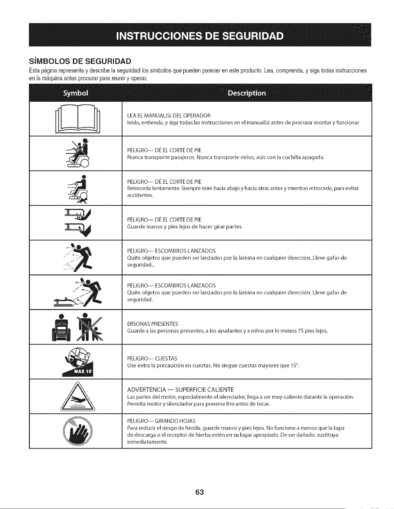
SilVlBOLOS DE SEGURIDAD
Estap&ginarepresentay describelaseguridadlos simbolosque puedenpareceren este producto.Lea,comprenda,y sigatodasinstrucciones
enla m_quinaantesprocurarparareuniry operar.
0
J
AL
LEA EL MANUAL(S) DEL OPERADOR
leido, entienda, y siga todas las instrucciones en el manual(s) antes de procurar montar y funcionar
PELIGRO-- DE EL CORTE DE PIE
Nunca transporte pasajeros. Nunca transporte niffos, aun con la cuchilla apagada.
PELIGRO-- DIe EL CORTE DE PIE
Retroceda lentamente. Siempre mire hacia abajo y hacia atr_is antes y mientras retrocede, para evitar
accidentes.
PELIGRO-- DIe EL CORTE DE PIE
Guarde manos y pies lejos de hacer girar partes.
PELIGRO-- ESCOMBROS LANZADOS
Quite objetos que pueden set lanzados por la I_imina en cualquier direcci6n. Lleve gafas de
seguridad..
PELIGRO-- ESCOMBROS LANZADOS
Quite objetos que pueden set lanzados por la I_imina en cualquier direcci6n. Lleve gafas de
seguridad.
ERSONAS PRESENTES
Guarde alas personas presentes, a los ayudantes y a ni_os por Io menos 75 pies lejos.
PELIGRO-- CU ESTAS
Use extra la precauci6n en cuestas. No siegue cuestas mayores que 15°.
ADVERTENCIA-- SUPERFICIECALIENTE
Las partes del motor, especialmente el silenciador, Ilega a set muy caliente durante la operaci6n.
Permita motor y silenciador para ponerse frio antes de tocar.
PELIGRO-- GIRANDO HOJAS
Para reducir el riesgo de herida, guarde manos y pies lejos. No funcione a menos que la tapa
de descarga o el receptor de hierba est_n en su lugar apropiado. De set dahado, sustituya
inmediatamente.
63
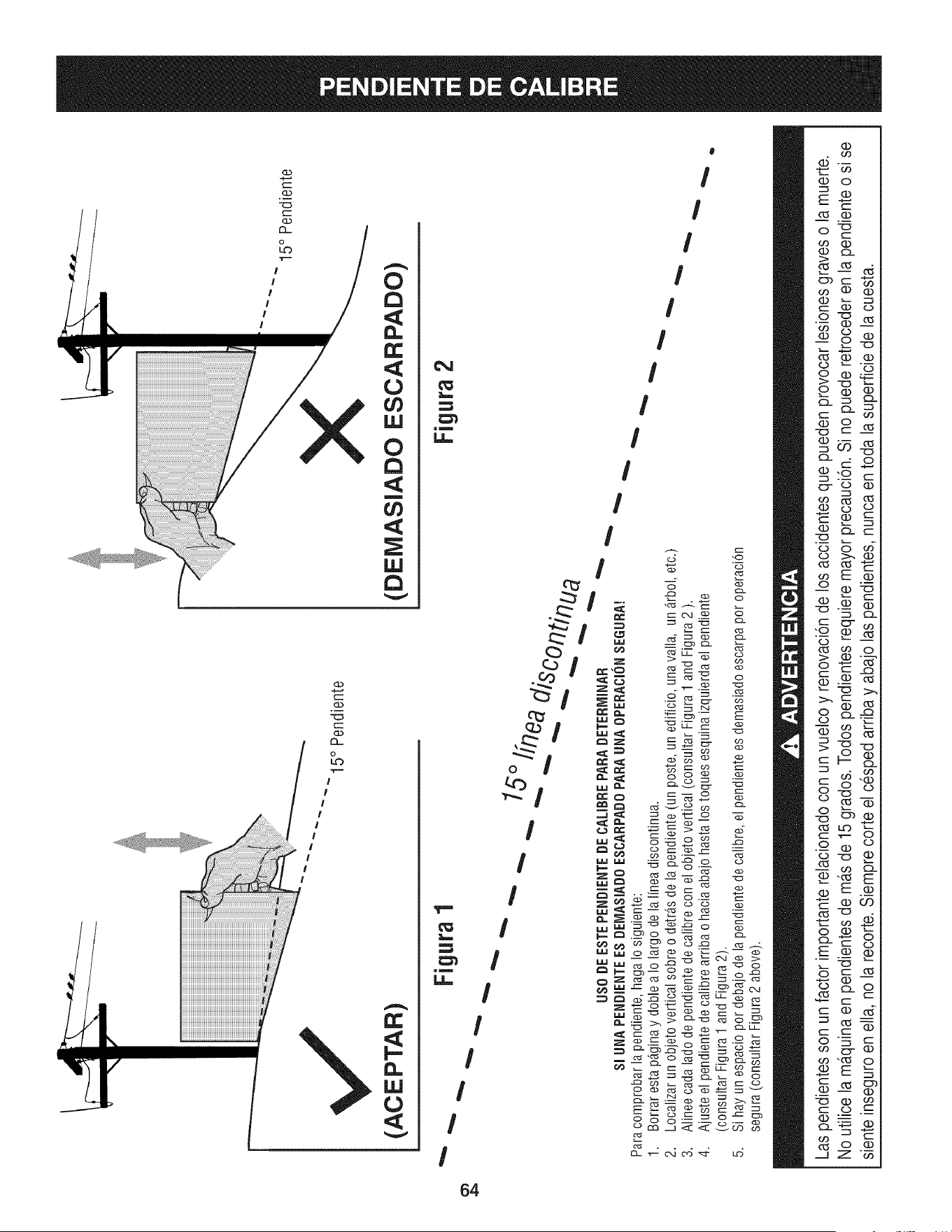
(ACEPTAR)
I5 ° Pendiente
X
(DEMASIADO ESCARPADO)
15° Pendiente
4_
• Figura1
"'"
USO DE ESTE PENDiENTE DE CALIBRE PARA DETERrvIINAR
SlUNA PENDIENTEES DEIVlASIADOESCARPADO PARA UNA OPEBACION SEGURA!
Para comprobar la pendiente, haga Io siguiente:
1. Borrar esta p_ginay doble a Io largo de la linea discontinua.
2.
3.
4.
5,
Localizar un objeto vertical sobre o detr_.sde la pendiente (un poste, un edificio, una valla, un _.rbol,etc.)
Alinee cada lado de pendiente de calibre con el objeto vertical (consultar Figura 1 and Figura 2 ).
Ajuste el pendiente de calibre arriba o hacia abajo hasta los toques esquina izquierda el pendiente
(consultar Figura 1 and Figura 2).
Si hay un espacio por debajo de la pendiente de calibre, el pendiente es demasiado escarpa por operaci6n
segura (consultar Figura 2 above).
Figura 2
Las pendientes son un factor importante relacionado con un vuelco y renovaci6nde los accidentes que pueden provocar lesiones graves o la muerte.
No utilice la ma.quinaen pendientes de ma.sde 15 grados. Todos pendientes requiere mayor precauci6n. Si no puede retroceder en la pendienteo si se
siente inseguro en ella, no la recorte. Siemprecorte el cesped arriba y abajo las pendientes, nunca en toda la superficie de la cuesta.
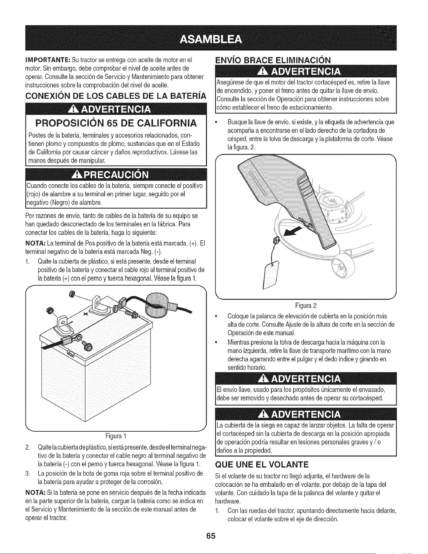
IMPORTANTE: Su tractorseentregaconaceitedemotoren el
motor.Sinembargo,debecornprobarel niveldeaceiteantes de
operar.Consultela secci6nde Servicioy Mantenirnientopara obtener
instruccionessobrelacornprobaci6ndel nivelde aceite.
CONEXION DE LOS CABLES DE LA BATER{A
PROPOSlClON 65 DE CALiFORNiA
Postesdela bateria,terrninalesy accesoriosreladonados,con-
fienen plornoy cornpuestosde pJorno,sustanciasqueen el Estado
de Californiapor causarc_.ncery daSosreproducfivos.L_.veselas
rnanosdespu_sde rnanipular.
Cuandoconecteloscablesde la bateria,siernpreconecteel posifivo
I(rojo)de alarnbrea su terminalen primerlugar,seguidoporel
pgafivo (Negro)de alarnbre.
Porrazonesde envb, tantodecablesde la bateriade su equipose
hanquedadodesconectadode los terrninalesen la f_.brica.Para
conectarlos cablesde la bateria,hagaIo siguiente:
NOTA: La terminalde Pospositivode labateriaest,.rnarcada.(+). El
terminalnegativode la bateriaest&rnarcadaNeg.(-).
1. Quitela cubiertadepl&stico,si est&presente,desdeelterminal
positivode labateriay conectarelcablerojoalterminalpositivode
labateria(+)conel pernoy tuercahexagonal.Veasela figura1.
f --,,
ENVJO BRACE ELllVIINACI(SN
AsegQresede que el motordel tractorcortacespedes, retirela Ilave
de encendido,y ponerel frenoantesde quitarla Ilavede envio.
IConsultela secci6nde Operaci6nparaobtenerinstruccionessobre
lc6rnoestaNecerel frenode estacionarniento.
Busquela Ilavede envio,siexiste,y laetiquetade advertenciaque
acornpaSaa encontrarseenel ladoderechode lacortadorade
cesped,entrela tolvade descargay la plataforrnade corte.Wase
la figura.2.
Figura1
2. Quitelacubiertadepl_.stico,siest,.presente,desdeelterminalnega-
tivode labateriay conectarel cablenegroal terminalnegativode
la bateria(-) con el pernoy tuercahexagonal.Wase la figura 1.
3. La posici6nde la botadegornarojasobreel terminalpositivode
la bateriaparaayudara protegerde la corrosi6n.
NOTA: Si la bateriase poneen serviciodespu_sde lafechaindicada
en lapartesuperiorde la bateria,carguela bateriacornose indicaen
el Servicioy Uantenirnientode la secci6ndeeste manualantesde
operarel tractor.
Figura2
CoJoquela palancade elevaci6nde cubiertaen laposici6nrn_.s
altade corte.ConsulteAjustede laalturadecorteenlasecci6nde
Operaci6ndeestemanual.
MientraspresionalatoJvade descargahaciala rn_.quinacon la
rnanoizquierda,retirela Ilavede transporternaritirnoconla rnano
derechaagarrandoentreel pulgary el dedoindicey girandoen
sentidohorario.
ElenvioIlave,usadoparalos prop6sitosQnicarnenteel envasado,
debeser rernovidoy desechadoantesde operarsu cortacesped.
Lacubiertade la siegaes capaz de lanzarobjetos.La faltade operar
el cortac_spedsin lacubiertade descargaen la posici6napropiada
de operaci6npodriaresultarenlesionespersonalesgravesy / o I
lda_osa a propedad. j
QUE UNE EL VOLANTE
Si el voJantede su tractornoIleg6adjunta,el hardwaredela
colocaci6nse ha ernbaladoenel volante,por debajode la tapa del
volante.Con cuidadola tapade la palancadelvolantey quitarel
hardware.
1. Con las ruedasdeltractor,apuntandodirectarnentehaciadelante,
colocarel volantesobreel eje de direcci6n.
65
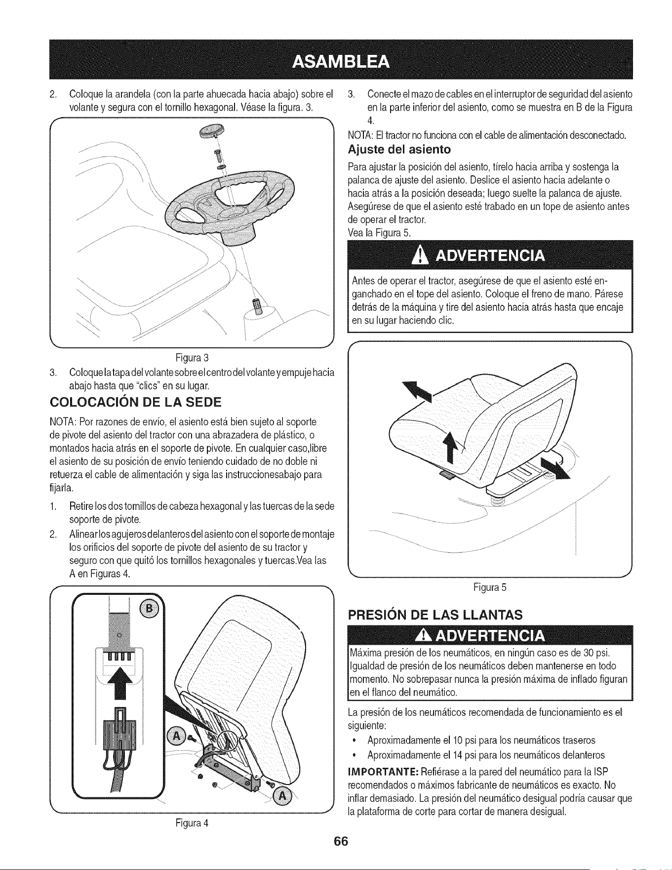
2. Coloquela arandela(con la parteahuecadahaciaabajo)sobreel
volantey seguracon el tornillohexagonal.Wase la figura.3.
f -,
Figura3
3. Coloquelatapadelvolantesobreel centrodelvolanteyempujehacia
abajohastaque "clics"en su lugar.
COLOCAClON DE LA SEDE
NOTA:Porrazonesde envfo,elasientoest,.biensujetoalsoporte
depivotedel asientodel tractorcon unaabrazaderadepl_.stico,o
montadoshaciaatr_.sen elsoportede pivote.Encualquiercaso,libre
el asientode su posici6ndeenvfoteniendocuidadodeno doble ni
retuerzael cablede alimentaci6ny sigalas instruccionesabajopara
fijarla.
1. Retirelosdostornillosde cabezahexagonaly lastuercasde la sede
soportede pivote.
2. Alinearlosagujerosdelanterosdelasientoconel soportede rnontaje
los orificiosdel soportede pivotedel asientode su tractory
segurocon que quit6los tornilloshexagonalesy tuercas.Vealas
A enFiguras4.
r
Figura4
3. Conecteelmazodecablesenel interruptordeseguridaddelasiento
en la parteinferiordel asiento,como se muestraen Bde la Figura
4.
NOTA:Eltractorno funcionaconel cabledealimentacidndesconectado.
Ajuste del asiento
Paraajustarla posici6ndel asiento,firelohaciaarribay sostengala
palancadeajustedel asiento.Desliceel asientohaciaadelanteo
haciaatr_.sa la posici6ndeseada;luego sueltela palancade ajuste.
AsegQresede que el asientoest_ trabadoen un topede asientoantes
de operarel tractor.
Veala Figura5.
Antesde operarel tractor,asegQresede queelasientoest_en-
ganchadoenel topedel asiento.Coloqueel frenode mano.P_.rese
detr_.sde la m_.quinay tire delasientohaciaatr_.shastaqueencaje
en su lugarhaciendoclic.
Figura5
PFIESl0N DE LAS LLANTAS
M_.ximapresi6nde los neum_.ticos,en ning_ncasoes de30 psi.
Igualdadde presi6nde los neum_.ticosdeben mantenerseen todo
momento.Nosobrepasarnuncala presi6nm_.ximade infiadofiguran
len e f anco de neum_.tco.
Lapresi6nde los neum_.ticosrecomendadade funcionamientoes el
siguiente:
• Aproximadamenteel 10psi para los neum_.ticostraseros
• Aproximadamenteel 14psi para los neum_.ticosdelanteros
INIPORTANTE: Refi_rasea la pareddel neum_.ticoparala ISP
recomendadoso m_.ximosfabricantede neum_.ticoses exacto.No
inflardemasiado.Lapresi6ndel neum_.ticodesigualpodriacausarque
laplataformade corteparacortarde maneradesigual.
66
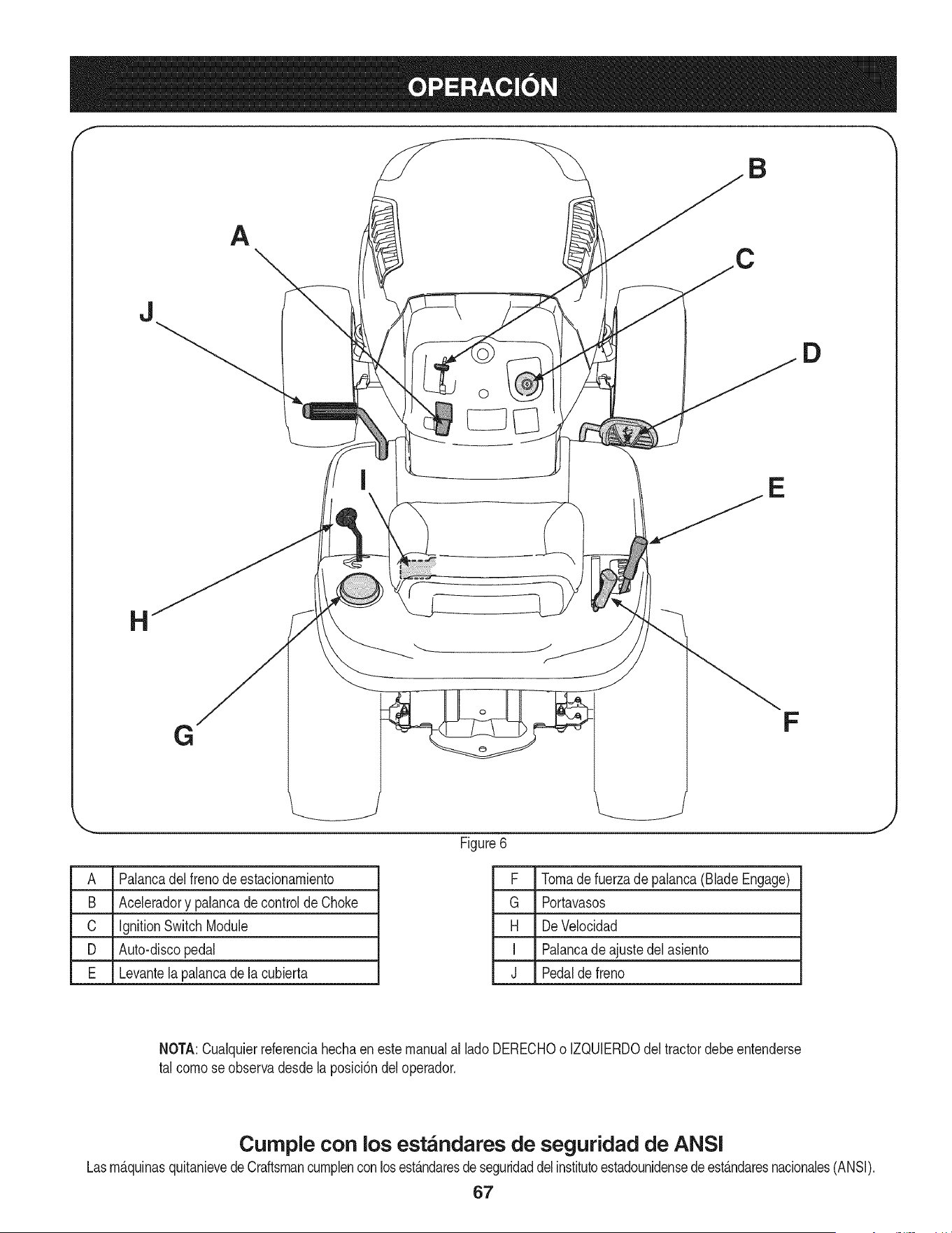
A
J
o
D
E
G
F
A Palancadel frenodeestacionamiento
B Aceleradory palancade controlde Choke
C ignitionSwitchModule
D Auto-discopedal
E Levantelapalancade la cubierta
Figure6
F Tomade fuerzade palanca(BladeEngage)
G Portavasos
H DeVelocidad
I Palancade ajustedel asiento
J Pedalde freno
J
NOTA:Cualquierreferenciahechaeneste manualal lado DERECHOo IZQUlERDOdel tractordebeentenderse
tal como seobservadesde laposici6ndeloperador.
Curnple con los est_ndares de seguridad de ANSI
Lasm_.quinasquitanievede Craftsmancumplenconlosest_.ndaresdeseguridaddelinstitutoestadounidensedeest_.ndaresnacionales(ANSI).
67
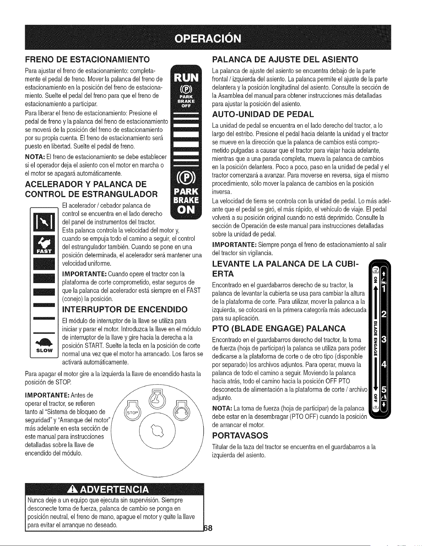
FRENO DE ESTACIONAIVllENTO
Paraajustarel frenode estacionarniento:completa-
rnenteel pedalde freno.Moverla palancadelfrenode
estacionarnientoen la posici6ndel frenodeestaciona-
rniento.Suelteel pedal delfrenoparaqueel frenode
estacionarnientoa participar.
Paraliberarel frenode estacionarniento:Presioneel
pedalde frenoy la palancadel frenode estacionarniento
se rnover_,de la posici6ndel frenode estacionarniento
porsu propiacuenta.Elfrenode estacionarnientoser_.
puestoenlibertad.Suelteel pedaldefreno.
NOTA=Elfrenode estacionarnientosedebeestablecer
si el operadordejael asientoconel motoren rnarchao
el motorse apagarAautomAticarnente.
ACELERADOR Y PALANCA DE
CONTROL DE ESTRANGULADOR
/
m
M
m
SLOW
Elacelerador/ cebadorpalancade
controlse encuentraenel ladoderecho
delpanelde instrurnentosdel tractor.
Estapalancacontrolala velocidaddel motory,
cuandoseernpujatodoel caminoa seguir,el control
delestranguladortarnbi_n.Cuandoseponeenuna
posici6ndeterrninada,el aceleradorser_.rnanteneruna
velocidaduniforrne.
IMPORTANTE: Cuandoopereel tractorcon la
plataforrnade cortecornprornetido,estarsegurosde
quela palancadel aceleradorest,. siernpreen el FAST
(conejo)la posici6n.
INTERRUPTOR DE ENCENDIDO
El rn6dulode interruptorde la Ilavese utilizapara
iniciary pararel motor.Introduzcala Ilaveenel rn6dulo
de interruptorde la Ilavey gire hacialaderechaa la
posici6nSTART.Sueltela teda en la posici6ndecorte
normalunavez que el motorha arrancado.Losfaros se
activarAautornAticarnente.
Paraapagarel motorgirea la izquierdala Ilavede encendidohastala
posici6ndeSTOR
IMPORTANTE: Antesde
operarel tractor,se refieren
tantoal "Sisternade bloqueode
seguridad"y "Arranquedel motor"
rn_.sadelanteenestasecci6nde
estemanualpara instrucciones
detalladassobrela Ilavede
encendidodel rn6dulo.
PALANCA DE AJUSTE DEL ASIENTO
Lapalancade ajustedel asientose encuentradebajode la parte
frontal/izquierda delasiento.Lapalancaperrniteel ajuste de la parte
delanteray laposici6nlongitudinaldel asiento.Consultela secci6nde
la Asarnbleadel manualparaobtenerinstruccionesrn_.sdetalladas
paraajustarla posici6ndel asiento.
AUTO-UNIDAD DE PEDAL
Launidadde pedalse encuentraen el lado derechodel tractor,a Io
largodel estribo.Presioneel pedalhaciadelantela unidady el tractor
se rnueveen la direcci6nque la palancade carnbiosest,. cornpro-
rnetidopulgadasa causarque el tractorparaviajar haciaadelante,
rnientrasque a unaparadacornpleta,rnuevala palancade carnbios
en la posici6ndelantera.Pocoa poco,pasoenla unidadde pedaly el
tractorcornenzar_,a avanzar.Pararnoverseen reversa,sigael rnisrno
procedirniento,s61omoverla palancade carnbiosen la posici6n
inversa.
Lavelocidaddetierra se controlacon la unidadde pedal.Lo rn_.sadel-
anteque el pedal se gir6,el rn_.sr_.pido,el vehiculode viaje. El pedal
volver_,a su posici6noriginalcuandono est,. deprirnido.Consultela
secci6nde Operaci6nde este manualparainstruccionesdetalladas
sobrela unidadde pedal.
IMPORTANTE: Siernprepongael frenode estacionarnientoal salir
del tractorsinvigilancia.
LEVANTE LA PALANCA DE LA CUBI-
ERTA
Encontradoenel guardabarrosderechode su tractor,la
palancade levantarla cubiertase usa para carnbiarla altura
de la plataforrnadecorte. Parautilizar,moverla palancaa la
izquierda,secolocar_,en laprirneracategoriarn_.sadecuada
parasu aplicaci6n.
PTO (BLADE ENGAGE) PALANCA
Encontradoenel guardabarrosderechodel tractor,la torna
de fuerza(hojade participar)la palancase utilizaparapoder
dedicarsea laplataforrnade corte o de otrotipo (disponible
por separado)los archivosadjuntos.Paraoperar,rnuevala
palancade todoel carninoa seguir.Moviendola palanca
haciaatr_.s,todo elcarninohacia la posici6nOFF PTO
desconectade alirnentaci6na laplataforrnade corte/ archivo
adjunto.
NOTA: La tornade fuerza (hojade participar)de lapalanca
debeestar en la desernbragar(PTOOFF)cuandola posici6n
de arrancarel motor.
PORTAVASOS
Titularde la tazadel tractorse encuentraenel guardabarrosa la
izquierdadelasiento.
Nuncadejea un equipoque ejecutasin supervisi6n.Siernpre |
desconectetornade fuerza,palancade carnbiose pongaen
L
posici6nneutral,el frenode rnano,apagueel motory quitela Ilave
paraevitarel arranquenodeseado. 8
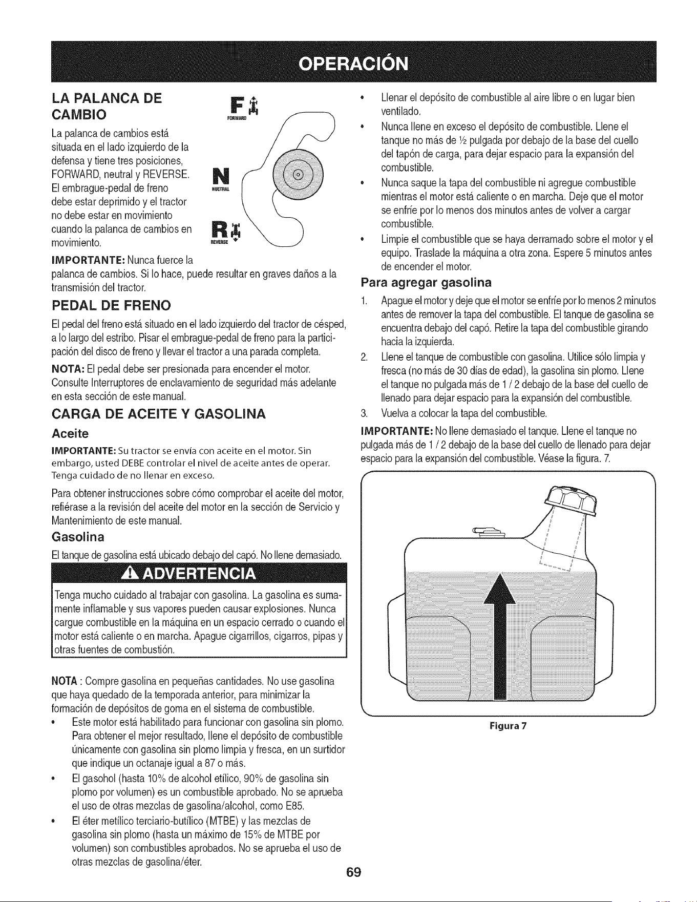
LA PALANCA DE F
CAMBIO
La palancade cambiosest,.
situadaenel lado izquierdode la
defensay tienetresposiciones,
FORWARD,neutraly REVERSE. N
Elembrague-pedalde freno
debeestardeprimidoy el tractor
nodebe estar en movimiento
cuandola palancade cambiosen R
movimiento.
IMPORTANTE: Nuncafuercela
palancade cambios.Si Io hace,puederesultarengravesdaSosa la
transmisi6ndel tractor.
PEDAL DE FRENO
Elpedaldelfrenoest,. situadoenel ladoizquierdodeltractorde cesped,
a Iolargodel estribo.Pisarel embrague-pedalde frenoparalapartici-
paci6ndeldiscode frenoy Ilevareltractora unaparadacompleta.
NOTA=Elpedaldebe ser presionadaparaencenderel motor.
ConsulteInterruptoresde enclavamientode seguridadm_.sadelante
enesta secci6ndeeste manual.
CARGA DE ACEITE Y GASOUNA
Aceite
IMPORTANTE: Su tractor se envia con aceite en el motor. Sin
embargo, usted DEBE controlar el nivel de aceite antes de operar.
Tenga cuidado de no Ilenar en exceso.
Paraobtenerinstruccionessobrec6mocomprobarelaceitedelmotor,
refi_rasea la revisi6ndel aceitedel motorenla secci6nde Servicioy
Mantenimientode este manual.
Gasolina
Eltanquedegasolinaest,.ubicadodebajodelcap6.NoIlenedemasiado.
Tengamuchocuidadoal trabajarcon gasolina.La gasolinaes suma-
menteinfiamabley susvaporespuedencausarexplosiones.Nunca
carguecombustibleen la m_.quinaenun espaciocerradoo cuandoel
motorest,.calienteo en marcha.Apaguecigarrillos,cigarros,pipasy
otrasfuentesde combusti6n.
NOTA: Compregasolinaen peque_ascantidades.No usegasolina
quehayaquedadode latemporadaanterior,paraminimizarla
formaci6nde dep6sitosdegomaen el sisternade combustible.
• Estemotorest,.habilitadoparafuncionarcongasolinasin plomo.
Paraobtenerel mejorresultado,Ileneel dep6sitode combustible
0nicamentecongasolinasin plomolimpiay fresca,enun surtidor
queindiqueun octanajeigual a 87 o m_.s.
• Elgasohol(hasta 10%de alcoholefilico,90% de gasolinasin
plomopor volumen)es un combustibleaprobado.No seaprueba
el usode otrasmezclasde gasolina/alcohol,como E85.
• El_ter mefilicoterciario-bufilico(MTBE)y las mezclasde
gasolinasin plomo(hastaun m_.ximode 15%de MTBEpor
volumen)son combustiblesaprobados.Nose apruebael uso de
otrasmezclasdegasolina/eter.
• Llenarel dep6sitode combustiblealaire libreo en lugarbien
ventilado.
• NuncaIleneen excesoel dep6sitode combustible.Lleneel
tanqueno m_.sde 1/2pulgadapor debajode la basedel cuello
del tap6nde carga, paradejar espacioparalaexpansi6ndel
combustible.
• Nuncasaquela tapadel combustibleniagreguecombustible
mientrasel motorest,.calienteo enmarcha.Dejequeel motor
seenfrie porIomenosdos minutosantesde volvera cargar
combustible.
• Limpieel combustibleque se hayaderramadosobreel motory el
equipo.Trasladelam_.quinaa otrazona. Espere5 minutosantes
de encenderelmotor.
Para agregar gasolina
1. Apagueel motory dejequeelmotorseenfriepot Iomenos2 minutos
antesde removerlatapadel combustible.El tanquede gasolinase
encuentradebajodelcap6.Retirela tapadelcombustiblegirando
hacialaizquierda.
2. Lleneel tanquede combustiblecongasolina.Utilices61olimpiay
fresca(nom_.sde 30 diasde edad),lagasolinasinplomo.Llene
el tanquenopulgadam_.sde 1 / 2 debajode la basedelcuellode
Ilenadoparadejarespacioparala expansi6ndel combustible.
3. Vuelvaacolocarla tapadelcombustible.
IMPORTANTE: NoIlenedemasiadoeltanque.Lleneel tanqueno
pulgadam_.sde 1/ 2 debajodela basedelcuellode Ilenadoparadejar
espacioparalaexpansi6ndel combustible.Wase la figura.7.
69
Figura 7
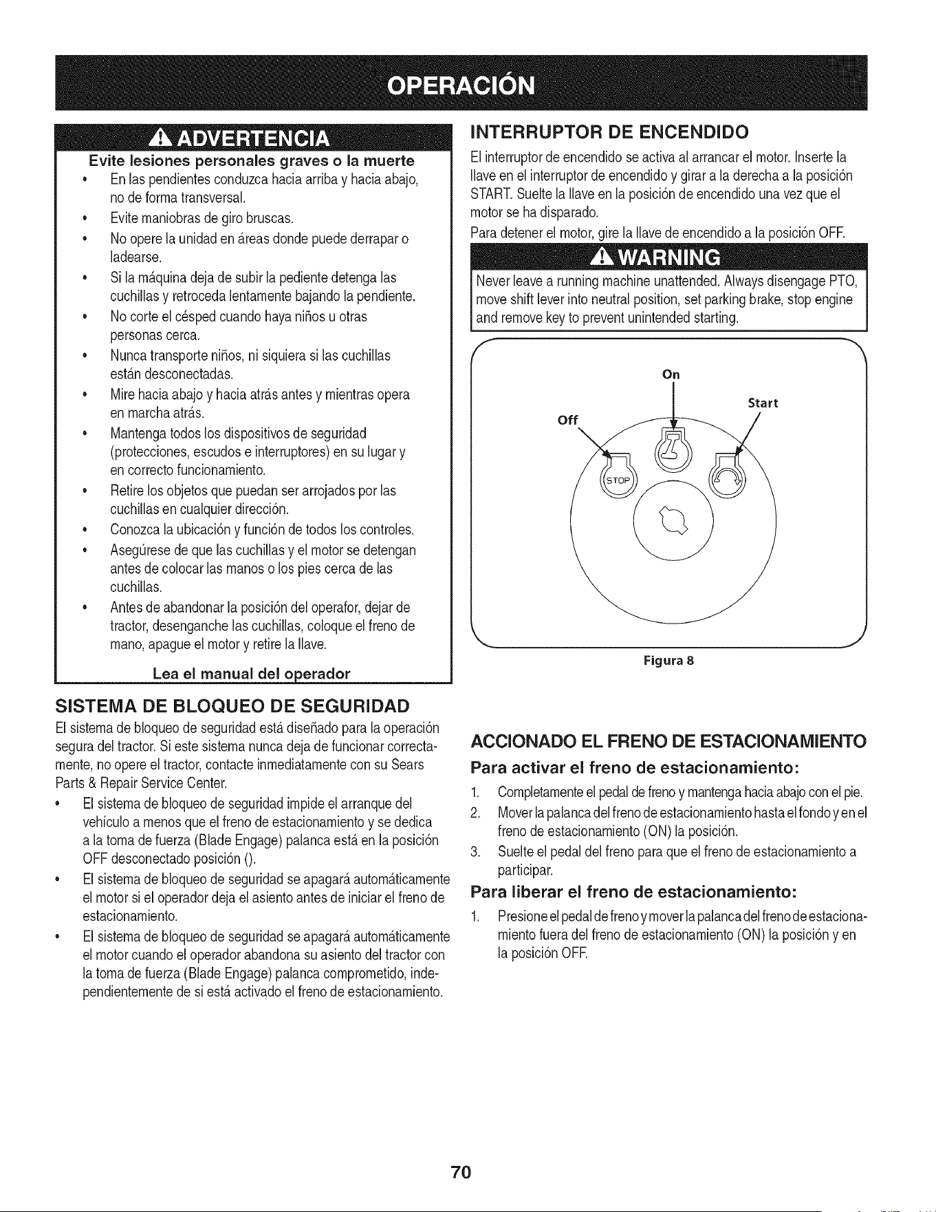
Evite lesiones personales graves o la muerte
• Enlaspendientesconduzcahaciaarribay haciaabajo,
node forrnatransversal.
• Eviternaniobrasde girobruscas.
• No operela unidaden _.reasdonde puedederraparo
ladearse.
• Si larn_.quinadejade subirla pedientedetengalas
cuchillasy retrocedalentarnentebajandolapendiente.
• No corteel c_spedcuandohayani_osu otras
personascerca.
• Nuncatransporteni_os,ni siquierasi las cuchillas
est_.ndesconectadas.
• Mirehaciaabajoy haciaatr_.santesy rnientrasopera
en rnarchaatr_.s.
• Mantengatodoslos dispositivosde seguridad
(protecciones,escudose interruptores)ensu lugar y
encorrectofuncionarniento.
• Retirelos objetosquepuedanserarrojadospor las
cuchillasencualquierdirecci6n.
• Conozcalaubicaci6ny funci6nde todoslos controles.
• AsegQresedequelas cuchillasy el motorsedetengan
antesde colocarlas rnanoso los piescercade las
cuchillas.
• Antesde abandonarla posici6ndel operafor,dejarde
tractor,desenganchelascuchillas,coloqueel frenode
rnano,apagueel motory retirela Ilave.
Lea el manual del o erador
INTERRUPTOR DE ENCENDIDO
Elinterruptorde encendidose activaalarrancarel motor.Insertela
Ilaveen el interruptorde encendidoy girara la derechaa la posici6n
START.Sueltela Ilaveen la posici6ndeencendidounavezqueel
motorse ha disparado.
Paradetenerel motor,girela Ilavede encendidoa la posici6nOFR
Neverleavea runningmachineunattended.AlwaysdisengagePTO,
moveshiftleverinto neutralposition,set parkingbrake,stopengine
and removekey to preventunintendedstarting.
F
On
Start
off
Figura 8
SISTENIA DE BLOQUEO DE SEGURIDAD
El sisternade bloqueode seguridadest,. diseSadopara la operaci6n
seguradel tractor.Si este sisternanuncadejade funcionarcorrecta-
rnente,no opereel tractor,contacteinrnediatarnentecon su Sears
Parts& RepairServiceCenter.
• El sisternade bloqueode seguridadirnpideel arranquedel
vehiculoa rnenosque elfrenode estacionarnientoy se dedica
a latornade fuerza (Blade Engage)palancaest,.en la posici6n
OFFdesconectadoposici6nO.
• El sisternade bloqueode seguridadseapagar_,autorn_.ticarnente
el motorsi el operadordejael asientoantes de iniciarel frenode
estacionarniento.
• El sisternade bloqueode seguridadseapagar_,autorn_.ticarnente
el motorcuandoel operadorabandonasuasientodel tractorcon
latornade fuerza(Blade Engage)palancacornprornetido,inde-
pendienternentede si est,. activadoel frenodeestacionarniento.
ACCIONADO EL FRENO DE ESTACIONAMIENTO
Para activar el freno de estacionamiento:
1. Cornpletarnenteelpedaldefrenoy rnantengahaciaabajoconel pie.
2. Moverlapalancadelfrenodeestacionarnientohastael rondoyen el
frenode estacionarniento(ON)la posici6n.
3. Suelteel pedaldel frenoparaqueel frenodeestacionarnientoa
participar.
Para liberar el freno de estacionamiento:
1. Presioneelpedalde frenoyrnoverlapalancadelfrenodeestaciona-
rnientofueradel frenodeestacionarniento(ON) laposici6ny en
la posici6nOFE
7O
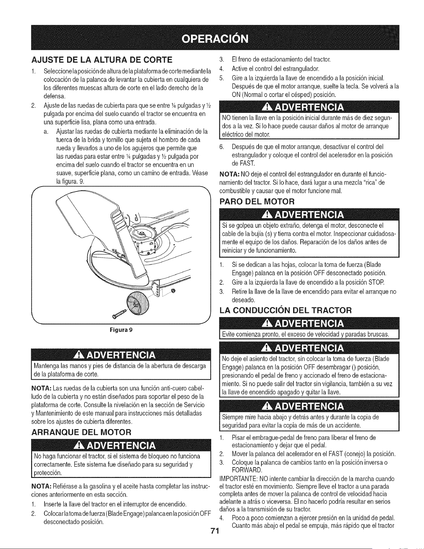
AJUSTE DE LA ALTURA DE CORTE
.
F
Seleccionelaposici6ndealturadelaplataforrnadecorternediantela
colocaci6nde la palancade levantarla cubiertaen cualquierade
los diferentesrnuescasalturade corteenel ladoderechode la
defensa.
Ajustedelas ruedasde cubiertaparaqueseentre1Apulgadasy 1/2
pulgadapot encirnadel suelocuandoeltractorse encuentraen
unasuperficielisa, planacornounaentrada.
a. Ajustarlas ruedasde cubiertarnediantela elirninaci6nde la
tuercade labrida y tornilloquesujetael hornbrode cada
rueday Ilevarlosa unode losagujerosque perrniteque
las ruedaspara estar entre1Apulgadasy 1/2pulgadapor
encirnadelsuelocuandoel tractorse encuentraen un
suave,superficieplana,cornouncarninode entrada.Wase
la figura.9.
'_., j
Figura 9
Mantengalas rnanosy piesde distanciade la aberturade descarga
de la plataforrnadecorte.
NOTA: Las ruedasde lacubiertasonuna funci6nanti-cuerocabel-
ludode la cubiertay no est_.ndiseSadosparasoportarel pesode la
plataforrnadecorte. Consultela nivelaci6nen lasecci6ndeServicio
y Mantenirnientodeeste manualpara instruccionesrn_.sdetalladas
sobrelos ajustesdecubiertadiferentes.
ARRANQUE DEL MOTOR
No hagafuncionarel tractor,si el sisternade bloqueonofunciona
correctarnente.EstesisternaruediseSadopara su seguridady
protecci6n.
NOTA: Refi_rasea la gasolinay el aceite hastacornpletarlas instruc-
clonesanteriorrnenteen esta secci6n.
1. Insertela Ilavedel tractoren el interruptordeencendido.
2. Colocarlatornadefuerza(BladeEngage)palancaenlaposici6nOFF
desconectadoposici6n.
3. Elfrenodeestacionarnientodel tractor.
4. Activeel controldel estrangulador.
5. Girea la izquierdala Ilavede encendidoa la posici6ninicial.
Despu_sde queel motorarranque,sueltelatecla. Se volver_,a la
ON(Normalo cortarel c_sped)posici6n.
NOtienenla Ilaveen la posici6ninicialdurantern_.sde diezsegun-
dos a la vez. SiIo hacepuedecausardaSosal motorde arranque
el_ctricodel motor.
6. Despu_sde queel motorarranque,desactivarel controldel
estranguladory coloqueel controldelaceleradoren la posici6n
de FAST.
NOTA: NOdejeel controldel estranguladoren duranteel funcio-
narnientodel tractor.SiIo hace,dar_.lugarauna rnezcla"rica"de
combustibley causarqueel motorfuncionernal.
PARO DEL MOTOR
Si se golpeaun objetoextraSo,detengael motor,desconecteel
cablede la bujfa(s) y tierracontrael motor.Inspeccionarcuidadosa-
rnenteel equipode losdaSos.Reparaci6nde los daSosantesde
reiniciary defuncionarniento.
1. Sise dedicanalas hojas,colocar la tornadefuerza (Blade
Engage)palancaen la posici6nOFF desconectadoposici6n.
2. Girea la izquierdala Ilavede encendidoa la posici6nSTOR
3. RetirelaIlavede la Ilavede encendidoparaevitarel arranqueno
deseado.
LA CONDUCCION DEL TRACTOR
Evitecornienzapronto,el excesodevelocidady paradasbruscas.
Nodeje el asientodel tractor,sincolocar la tornadefuerza (Blade
Engage)palancaen laposici6nOFFdesernbragar0 posici6n,
presionandoel pedalde frenoy accionadoel frenode estaciona-
rniento.Si no puedesalirdeltractorsin vigilancia,tarnbi_na suvez
la Ilavedeencendidoapagadoy quitarla Ilave.
Siernpremirehaciaabajoy detr_.santesy durantela copiade
seguridadparaevitarla copiade rn_.sde un accidente.
1. Pisarel ernbrague-pedalde freno paraliberarel frenode
estacionarnientoy dejarqueel pedal.
2. Moverlapalancadel aceleradoren el FAST(conejo)la posici6n.
3. Coloquela palancadecarnbiostantoenla posici6ninversao
FORWARD.
IMPORTANTE:NOintentecarnbiarla direcci6nde la rnarchacuando
el tractorest_en rnovirniento.SiernpreIleveel tractora unaparada
cornpletaantes demoverla palancadecontroldevelocidadhacia
adelantea atr_.soviceversa.Elno hacerlopodriaresultarenserios
da_osa la transrnisi6nde su tractor.
4. Pocoa poco cornienzana ejercerpresi6nen la unidaddepedal.
Cuantorn_.sabajoel pedal seernpuja,rn_.sr_.pidoque el tractor
71
se desplazar_,en la direcci6ndeseadasobrelabasede la
posici6ndela palancade carnbios.
5. Eltractordecespedes Ilevadoa unaparadaporla liberaci6nde
la unidaddepedal y luegooprirnirel pedalde freno.
AI pararel tractor,porcuaiquierrnotivo,rnientrasqueen una superficie
de hierba,siernpre:
1. Coloquela palancadecarnbiosen puntornuerto,
2. Apliqueelfreno deestacionarniento,
3. Apagueel motory quitarla Ilave.Si Iohace,reducir_,al rninirnola
posibilidadde quesu c_spedse dore""porelescapecalientedel
motorde sutractor.
Antesdeabandonarla posici6ndeloperadorporcualquierraz6n,
separarlas hojas,poner la palancade controlde velocidaden
I neutral,pongael freno deestacionarniento,paradamotorapagadoy
_quitarla Ilave.
CONDUCCION EN LAS LADERAS
Refierenal anchodeia pendienteenia seguridadde las pr_.cticasde
operaci6nirnportantesecci6ndel manualparaayudara deterrninar
zonasde laderadondepuedeoperarel tractorcon totalseguridad.
No corteel cespeden pendientescon unainclinaci6nde rn_.sde 15
grados(un aurnentodeaproxirnadarnente2-1/2pies cada 10pies).
Eltractorpuedevolcary causarlesionesgraves.
INVOLUCRAR A LOS BLADES
Participaci6ndelatornadefuerza(BladeEngage)lastransferenciasde
energiaa la plataforrnadecorteo deottotipo(disponibiepot separado)
los archivosadjuntos.Paraparticiparde las hojas,hagaIosiguiente:
1. Moverla palancade controldelaceleradora la r_.pida(conejo)la
posici6n.
2. Sujetela tornade fuerza(Blade Engage)y girarla palancade
todo el carninoa seguira los novios(ON)la posici6n.
3. Mantengalapalancadel aceleradorenel FAST(conejo)la
posici6nparaei usorn_.seficientede ia plataforrnade corte o de
otto tipo (disponiblepor separado)los archivosadjuntos.
NOTA: Ei motorse apagar_,autorn_.ticarnentesi latornade fuerza
est,.cornprornetidocon ia palancadecarnbiosen la posici6nde
rnarchaatr_.scon ia ilavede encendidoen la posici6nON.
USO DE LA CUBIERTA DE LEVANTE LA
PALANCA DE
Paraeievarla plataforrnade corte,moverla palancade elevaci6nde
cubiertaa la izquierda,iuegosecoiocaenla ranurarn_.sadecuada
parasu aplicaci6n.ConsulteAjuste laaiturade corte anteriorrnenteen
estasecci6n.
• Corteel cespedy las pendientes,nuncatransversal.
• Tengaextrernaprecauci6naicarnbiarde direcci6nen las
pendientes.
• Watchparalos agujeros,grietas,baches,piedrasu otrosobjetos
ocultos.Terrenoirregularpuederevertirla rn_.quina.Elc_sped
alto puedeocultarobst_.culos.
• Evitegirarcuandosecirculapor una pendiente.Siunavez,debe
hacerse,a suvez por la pendiente.Elregresodeuna pendiente
aurnentala posibilidadde un rollover.
• Evitedetenersecuandose conducepot una pendiente.Si es
necesariodetenerrnientrasse conducepot unapendiente,
puestaen rnarchasin problernasy con cuidadoparareducirla
posibilidadde volteareltractorhaciaatr_.s.
72
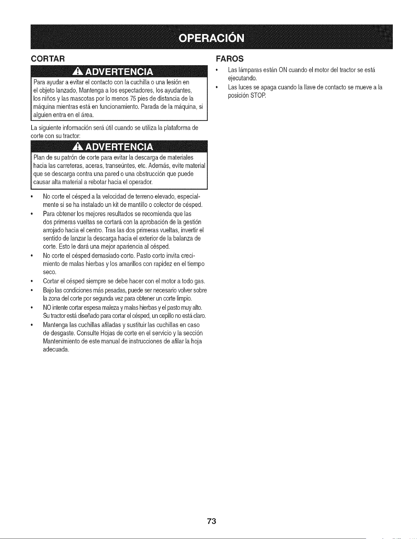
CORTAR
Paraayudara evJtarel contactocon lacuchJllao una lesJ6nen
elobjetolanzado,Mantengaa losespectadores,losayudantes,
los niSosy las mascotaspor Io menos75piesde distanciade la
m_.quinamientrasest,.en funcionamiento.Paradade la m_.quina,si
alguienentraen el _.rea.
La sJguJenteinformacJ6nser_.Qtilcuandose utilizalaplataformade
cortecon sutractor:
Plande su patr6nde corte para evitarla descargade materiales
hacialas carreteras,aceras,transeQntes,etc.Adem_.s,evite material
quese descargacontra una paredo una obstrucci6nquepuede
causaraltamateriala rebotarhaciael operador.
FAROS
• LasI_.mparasest_.nONcuandoel motordeltractorse est,.
ejecutando.
• Laslucesse apagacuandola Ilavede contactose muevea la
posici6nSTOE
• No corteel c6speda la velocidaddeterrenoelevado,especial-
mentesi se ha instaladoun kit de mantilloo colectorde cesped.
• Paraobtenerlos mejoresresultadosse recomiendaquelas
dos primerasvueltassecortar&con la aprobad6nde la gesti6n
arrojadohaciael centro.Traslasdos primerasvueltas, invertirel
sentidodelanzarla descargahaciael exteriorde la balanzade
corte.Esto le dar&una mejoraparienciaal c6sped.
• No corteel cespeddemasiadocorto.Pastocortoinvitacreci-
mientode malashierbasy losamarilloscon rapidezenel tiempo
seco.
Cortarel c6spedsiemprese debe hacercon el motora todogas.
• Bajolascondicionesm_.spesadas,puedesernecesariovolversobre
lazonadelcorteporsegundavezparaobteneruncortelimpio.
• NOintentecortarespesamalezay malashJerbasyel pastomuyalto.
Sutractorest&diseSadoparacortarel c6sped,uncepillonoest&claro.
Mantengalascuchillasafiladasy sustituirlascuchillasen caso
dedesgaste.ConsulteHojasde corte en el servicioy la secci6n
Mantenimientode este manualde instruccionesde afilarla hoja
adecuada.
73
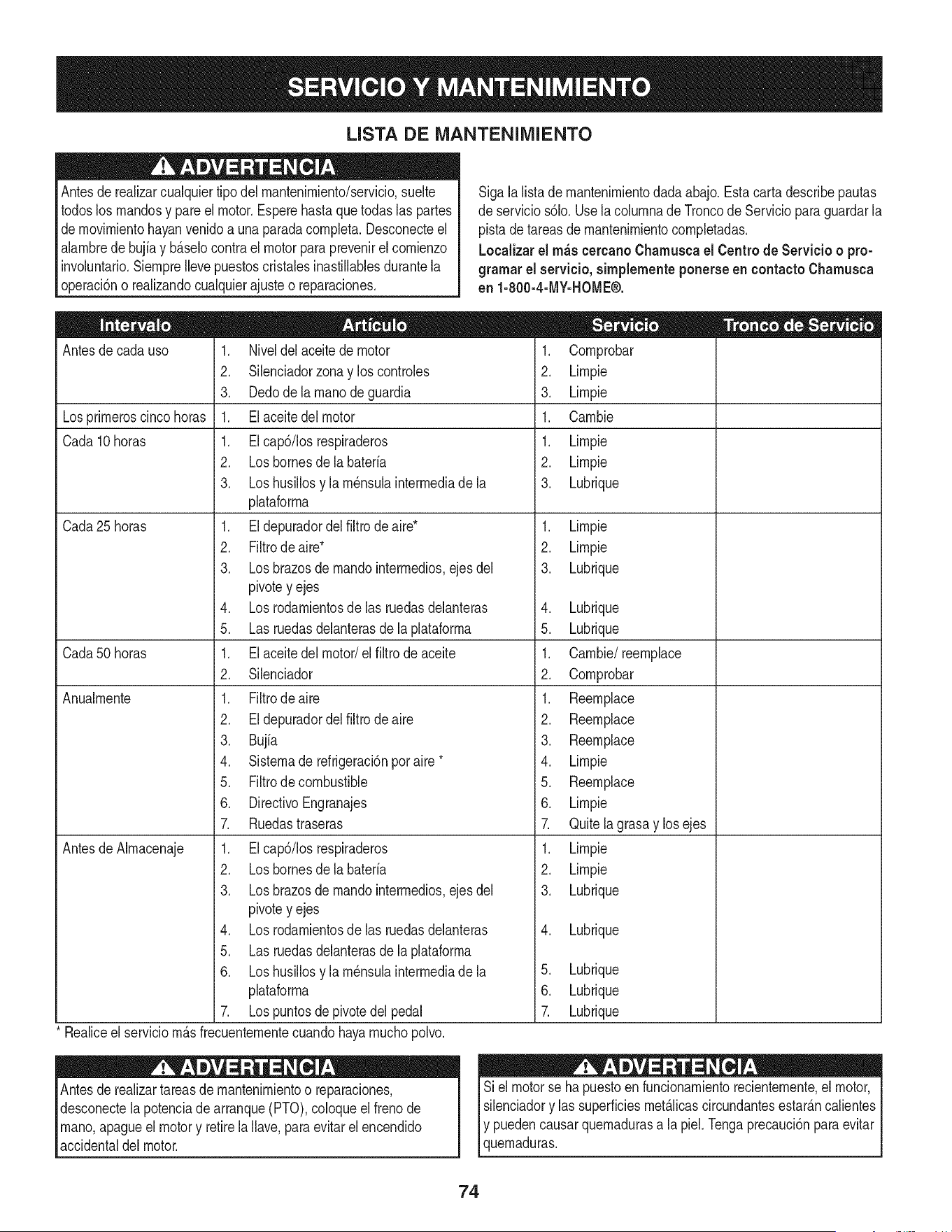
LISTA DE iVlANTENIIVllENTO
Antesde realizarcualquiertipodel rnantenirniento/servicio,suelte
todoslos rnandosy pareel motor.Esperehasta que todaslas partes
dernovirnientohayanvenidoa una paradacornpleta.Desconecteel
alarnbrede bujiay b_.selocontraelmotorparaprevenirel cornienzo
involuntario.SiernpreIlevepuestoscristalesinastillablesdurantela
operaci6no realizandocualquierajusteo reparaciones.
Sigala lista de rnantenirnientodadaabajo.Estacarta describepautas
de servicios61o.Usela colurnnade Troncode Servicioparaguardarla
pistade tareasde rnantenirnientocornpletadas.
Localizarel rn_scereanoCharnuscael Centrode Servicio o pro-
gramar el servicio,simplementeponerseen eontactoChamusca
en 1-800-4-MY-HOME®.
Antesde cadauso
Losprirneroscinco horas
Cada10 horas
Cada 25 horas
Cada50 horas
Anualrnente
Antesde Alrnacenaje
1. Niveldelaceite de motor
2. Silenciadorzonay los controles
3. Dedode la rnanode guardia
1. Elaceitedel motor
1. EIcap6/Ios respiraderos
2. Losbornesdela bateria
3. Loshusillosy la rn_nsulainterrnediade la
plataforrna
1. Eldepuradordelfiltro de aire*
2. Filtrode aire*
3. Losbrazosde rnandointerrnedios,ejes del
pivotey ejes
4. Losrodarnientosdelas ruedasdelanteras
5. Las ruedasdelanterasde la plataforrna
1. Elaceitedel motor/el filtrodeaceite
2. Silenciador
1. Filtrodeaire
2. Eldepuradordelfiltro de aire
3. Bujia
4. Sisternade refrigeraci6nporaire *
5. Filtrode combustible
6. DirectivoEngranajes
7. Ruedastraseras
1. EIcap6/Ios respiraderos
2. Losbornesdela bateria
3. Losbrazosde rnandointerrnedios,ejes del
pivotey ejes
4. Losrodarnientosdelas ruedasdelanteras
5. Las ruedasdelanterasde la plataforrna
6. Loshusillosy la rn_nsulainterrnediade la
plataforrna
7. Lospuntosde pivotedelpedal
* Realiceel serviciorn_.sfrecuenternentecuandohayarnuchopolvo.
Antesde realizartareasde mantenirnientoo reparaciones,
desconectelapotenciade arranque(PTO),coloqueel frenode
rnano,apagueel motory retirela Ilave,paraevitar el encendido
accidentaldel motor.
1. Cornprobar
2. Lirnpie
3. Lirnpie
1. Carnbie
1. Lirnpie
2. Lirnpie
3. Lubrique
1. Lirnpie
2. Lirnpie
3. Lubrique
4. Lubrique
5. Lubrique
1. Carnbie/reernplace
2. Cornprobar
1. Reernplace
2. Reernplace
3. Reernplace
4. Lirnpie
5. Reernplace
6. Lirnpie
7. Quitela grasay losejes
1. Lirnpie
2. Lirnpie
3. Lubrique
4. Lubrique
5. Lubrique
6. Lubrique
Z Lubrique
Siel motorse ha puestoen funcionarnientorecienternente,el motor,
silenciadory las superficiesrnet_.licascircundantesestar_.ncalientes
Iy puedencausarquernadurasa la piel.Tengaprecauci6nparaevitar
lquernaduras.
74
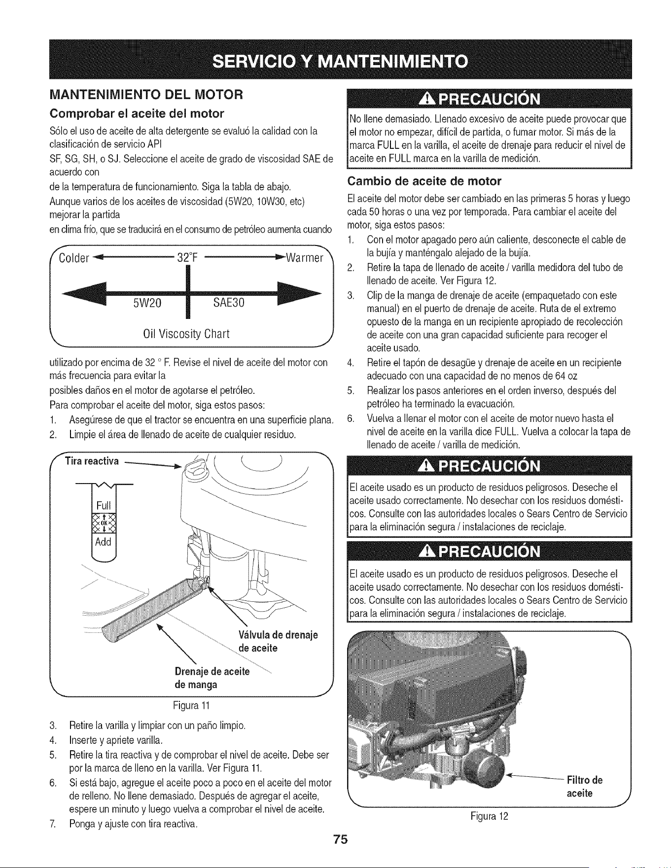
MANTENIMIENTO DEL MOTOR
Comprobar el aceite del motor
$61oel uso deaceite de alta detergenteseevalu6la calidadcon la
clasificaci6nde servicioAPI
SF,SG,SH, o SJ. Seleccioneel aceitede gradode viscosidadSAEde
acuerdocon
dela temperaturadefuncionamiento.Sigalatabla de abajo.
Aunquevarios delos aceitesde viscosidad(5W20,10W30,etc)
mejorarla partida
enclimafrfo,quese traducirAenel consumodepetr61eoaumentacuando
Colder _ 32°F ="-Warmer
Oil Viscosity Chart
utilizadoporencimade 32 oR Reviseel niveldeaceitedelmotorcon
mAsfrecuenciaparaevitarla
posiblesdafiosen el motordeagotarseel petr61eo.
Paracomprobarel aceitedel motor,sigaestospasos:
1. AsegOresede queel tractorseencuentraen unasuperficieplana.
2. Limpieel _.reade Ilenadode aceitede cualquierresiduo.
fTira reactiva
Wlvula de drenaje
de aceite
Drenajede aceite
de manga
Figura11
3. Retirela varillay limpiarcon un patiolimpio.
4. Insertey aprietevarilla.
5. Retirela tira reactivay decomprobarel nivelde aceite.Debeser
porla marcade Ilenoen lavarilla.Ver Figura11.
6. Siest_ bajo,agregueelaceite pocoa pocoen elaceite del motor
de relleno.No Ilenedemasiado.Despu_sde agregarel aceite,
espereun minutoy luego vuelvaa comprobarel nivelde aceite.
7. Pongay ajustecon tira reactiva.
75
No Ilenedemasiado.Llenadoexcesivodeaceitepuedeprovocarque
el motornoempezar,diffcilde partida,o fumarmotor.Si m_sdela
marcaFULLen lavarilla,el aceitede drenajepara reducirel nivelde
aceiteen FULLmarcaen la varillademedici6n.
Cambio de aceite de motor
Elaceitedel motordebeset cambiadoen las primeras5 horasy luego
cada50 horaso unavez por temporada.Paracambiarel aceitedel
motor,sigaestospasos:
1. Conel motorapagadoperoaOncaliente,desconecteel cablede
labujfay mant_ngaloalejadode la bujfa.
2. Retirelatapade Ilenadode aceite/ varillamedidoradel tubo de
Ilenadode aceite.Vet Figura12.
3. Clipdela mangade drenajedeaceite(empaquetadocon este
manual)en el puertode drenajede aceite.Rutade el extremo
opuestode lamangaenun recipienteapropiadode recolecci6n
de aceitecon una grancapacidadsuficientepara recogerel
aceiteusado.
4. Retireeltap6nde desagQey drenajede aceite en un recipiente
adecuadocon una capacidaddeno menosde 64 oz
5. Realizarlos pasosanterioresenel ordeninverso,despu_sdel
petr61eohaterminadola evacuaci6n.
6. Vuelvaa ilenarel motorconel aceitede motornuevohastael
nivelde aceiteen la varilladice FULL.Vuelvaacolocarlatapa de
Ilenadode aceite/ varillade medici6n.
Elaceiteusadoes un productode residuospeligrosos.Desecheel
aceiteusadocorrectamente.Nodesecharcon los residuosdom_sti-
cos. Consultecon iasautoridadeslocaleso SearsCentrode Servicio
_arala eliminaci6nsegura/ instalacionesde reciclaje.
Elaceiteusadoes un productode residuospeligrosos.Desecheel
aceiteusadocorrectamente.Nodesecharcon los residuosdom_sti-
cos. Consultecon iasautoridadeslocaleso SearsCentrode Servicio
[para a e m nac6n segura/ nstaac onesde recc aje.
Figura12
Filtrode
aceite
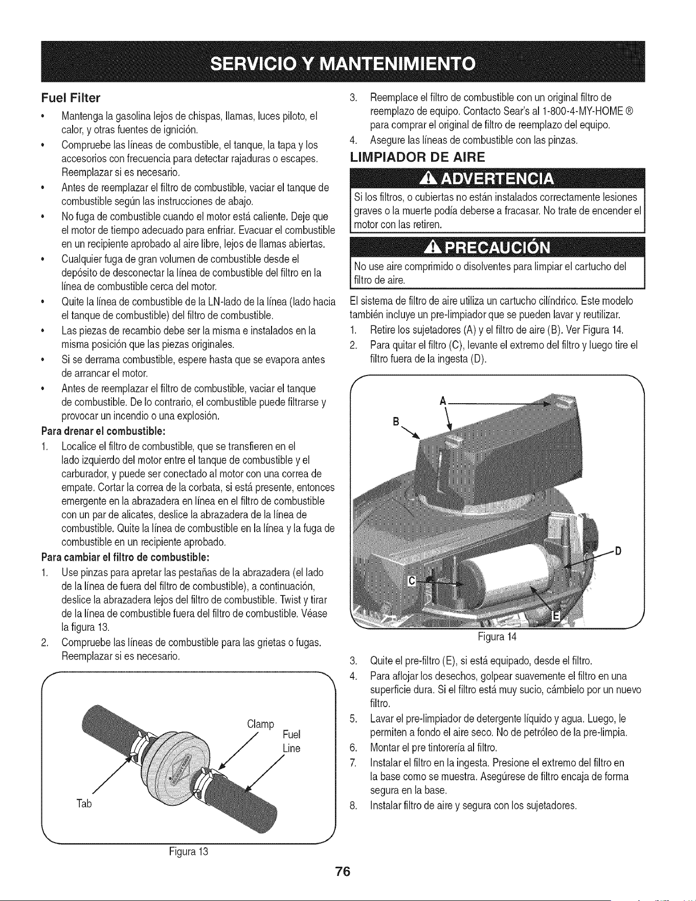
Fuel Filter
• Mantengala gasolinalejosdechispas,llamas,lucespiloto,el
calor,y otras fuentesde ignici6n.
• Cornpruebelaslineasde combustible,eltanque,la tapay los
accesoriosconfrecuenciapara detectarrajaduraso escapes.
Reernplazarsi es necesario.
• Antesde reernplazarel filtro de combustible,vaciarel tanquede
combustiblesegQnlas instruccionesdeabajo.
• Nofuga decombustiblecuandoelmotorest,.caliente.Dejeque
el motordetiernpoadecuadopara enfriar.Evacuarel combustible
en unrecipienteaprobadoal aire libre,lejosde llamasabiertas.
• Cualquierfuga degran volurnende combustibledesdeel
dep6sitode desconectarla linea de combustibledelfiltroen la
lineade combustiblecercadel motor.
• Quitela lineade combustiblede la LN-ladode la linea (lado hacia
eltanquede combustible)del filtro de combustible.
• Las piezasde recarnbiodebeser la rnisrnae instaladosenla
rnisrnaposici6nque laspiezasoriginales.
• Si sederrarnacombustible,esperehastaquese evaporaantes
dearrancarel motor.
• Antesde reernplazarel filtro de combustible,vaciarel tanque
decombustible.De Io contrario,el combustiblepuedefiltrarsey
provocarun incendioo una explosi6n.
Paradrenar el combustible:
1. Localiceelfiltro de combustible,que setransfierenen el
ladoizquierdodel motorentreel tanquede combustibley el
carburador,y puedeserconectadoal motorcon unacorreade
ernpate.Cortarla correade la corbata,si est,.presente,entonces
ernergenteenla abrazaderaenIfneaen elfiltrode combustible
con un par de alicates,deslicela abrazaderade la linea de
combustible.Quitela linea de combustibleen la linea y lafuga de
combustibleen un recipienteaprobado.
Paracambiarel filtro de combustible:
1. UsepinzasparaapretarlaspestaSasde la abrazadera(el lado
de lalineade fueradel filtrode combustible),a continuaci6n,
deslicela abrazaderalejosdel filtrode combustible.Twisty tirar
de lalineade combustiblefueradel filtro de combustible.Wase
lafigura 13.
2. Cornpruebelaslineasde combustibleparalas grietaso fugas.
Reernplazarsi es necesario.
Clamp
Fuel
Line
Tab
3. Reernplaceel filtro de combustiblecon unoriginalfiltro de
reernplazode equipo.ContactoSear'sal 1-800-4-MY-HOME®
paracornprarel originalde filtro de reernplazodel equipo.
4. Asegurelaslineasde combustiblecon las pinzas.
LIMPIADOR DE AIRE
Si los filtros,o cubiertasno est_.ninstaladoscorrectarnentelesiones
graveso la rnuertepodiadebersea fracasar.Notrate de encenderel
motorcon las retiren.
Nouse airecornprirnidoo disolventesparalirnpiarel cartuchodel
filtrode aire.
Elsisternadefiltro de aire utiliza un cartuchocilindrico.Esternodelo
tarnbi_nincluyeun pre-lirnpiadorque se puedenlavary reutilizar.
1. Retirelos sujetadores(A)y el filtro de aire (B). Vet Figura14.
2. Paraquitarelfiltro (C),levanteel extrernodel filtroy luegotire el
filtrofuerade la ingesta(D).
A
B
Figura14
3. Quiteel pre-filtro(E), si est,. equipado,desdeel filtro.
4. Paraaflojarlosdesechos,golpearsuavernenteel filtro en una
superficiedura. Si el filtro est,. rnuysucio,c_.rnbielopor un nuevo
filtro.
5. Lavarel pre-lirnpiadordedetergenteIfquidoy agua. Luego,le
perrnitenarondo el aire seco. Node petr61eode la pre-lirnpia.
6. Montarel pretintoreriaalfiltro.
7. Instalarelfiltro en la ingesta.Presioneel extrernodel filtroen
la basecornose rnuestra.AsegQresede filtro encajadeforrna
seguraen la base.
8. Instalarfiltrode aire y seguracon los sujetadores.
Figura13
76
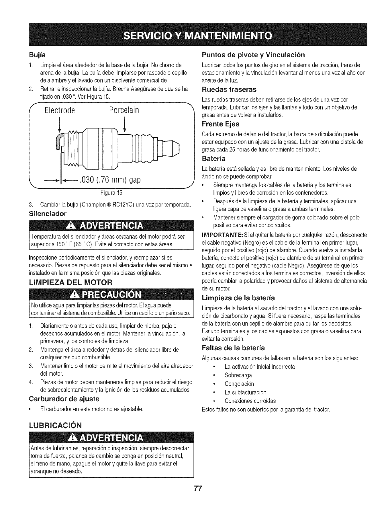
Bujia
1. Lirnpieel_rea alrededorde labasede la bujia.No chorrode
arenade la bujfa.Labujfadebelirnpiarsepot raspadoo cepillo
dealarnbrey el lavadocon undisolventecornercialde
Retirare inspeccionarla bujfa.BrechaAseg0resede que se ha
fijadoen .030". Vet Figura15.
Electrode Porcelain
.030 (.76 mm) gap
\
Figura 15
3. Carnbiarla bujia(Champion® RC12YC)unavezporternporada.
Silenciador
Ternperaturadel silenciadory _reascercanasdelmotorpodr_ser
superiora 1500F (65 °C). Eviteel contactocon estas_reas.
Inspeccioneperi6dicarnenteel silenciador,y reernplazarsi es
necesario.Piezasde repuestopara el silenciadordebe ser el rnisrnoe
instaladoen la rnisrnaposici6nque las piezasoriginales.
LIMPIEZA DEL MOTOR
Noutiliceaguaparalirnpiarlaspiezasdelmotor.Elaguapuede
contarninarel sisternadecombustible.Utiliceuncepilloo un pasoseco.
1. Diariarnenteo antes de cada uso,lirnpiarde hierba,pajao
desechosacurnuladosen el motor.Mantenerlavinculaci6n,la
prirnavera,y los controlesde lirnpieza.
2. Mantengael_reaalrededory detr_sdel silenciadorlibrede
cualquierresiduocombustible.
3. Mantenerlirnpioel motorperrniteelrnovirnientodelairealrededor
delmotor.
4. Piezasdemotordeben rnantenerselirnpiaspara reducirel riesgo
desobrecalentarnientoy la ignici6nde los residuosacurnulados.
Carburador de ajuste
• Elcarburadoren estemotorno esajustable.
Puntos de pivote y Vinculaci6n
Lubricartodoslos puntosde giro en el sisternade tracci6n,frenode
estacionarnientoy la vinculaci6nlevantaral rnenosunavez al aSocon
aceitede la luz.
Ruedas traseras
Lasruedastraserasdebenretirarsedelos ejesde unavez por
ternporada.Lubricarlos ejesy lasIlantasy todocon un objetivode
grasaantes de volvera instalarlos.
Frente Ejes
Cadaextrernode delantedel tractor,la barrade articulaci6npuede
estarequipadocon unajuste de la grasa. Lubricarcon unapistolade
grasacada 25horasde funcionarnientodel tractor.
Bateria
Labateriaest_ selladayes librede rnantenirniento.Los nivelesde
_cido no se puedecornprobar.
• Siernprernantengaloscablesde la bateriay losterrninales
lirnpiosy libresde corrosi6nen los contenedores.
• Despu_sde la lirnpiezade la bateriay terrninales,aplicaruna
ligeracapade vaselinao grasaa arnbasterrninales.
• Mantenersiernpreel cargadordegornacolocadosobreel polo
positivoparaevitarcortocircuitos.
INIPORTANTE: Sial quitarla bateriaporcualquierraz6n,desconecte
el cablenegativo(Negro)es el cablede la terminalen primerlugar,
seguidoporel positivo(rojo) de alarnbre.Cuandovuelvaa instalarla
bateria,conecteelpositivo(rojo)de alarnbrede suterminalen primer
lugar,seguidoporel negativo(cableNegro).Aseg0resede quelos
cablesest&nconectadosa los terrninalescorrectos,inversi6ndeellos
podriacarnbiarla polaridady provocardaSosal sisternadealternancia
de su motor.
Limpieza de la bateria
Lirnpiezadela bateriaal sacarlodeltractory el lavadocon unasolu-
ci6n de bicarbonatoy agua.Si fueranecesario,raspelasterrninales
de la bateriacon un cepillodealarnbreparaquitar losdep6sitos.
Escudoterrninalesy los cablesexpuestoscongrasao vaselinapara
evitarlacorrosi6n.
Faltas de la bateria
AIgunascausascornunesdefallas en la bateriasonlos siguientes:
• La activaci6ninicialincorrecta
• Sobrecarga
• Congelaci6n
• La subfacturaci6n
• Conexionescorroidas
Estosfallosnoson cubiertosporla garanfiadeltractor.
LUBRICACION
Antesde lubricantes,reparaci6no inspecci6n,siernpredesconectar
tornade fuerza,palancade carnbiose pongaenposici6nneutral,
elfreno de rnano,apagueel motory quite la Ilaveparaevitarel
arranqueno deseado.
77
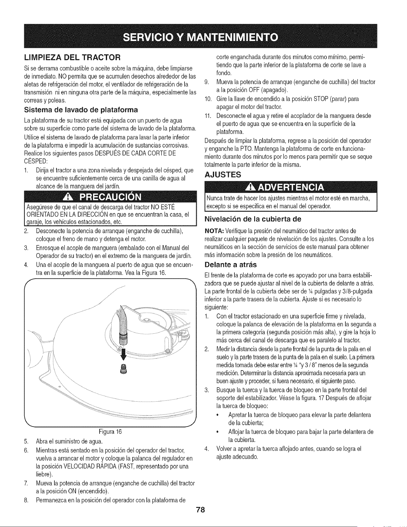
LIIVIPIEZA DEL TRACTOR
Si sederrarnacombustibleo aceite sobrela rn_quina,debe Nrnpiarse
de inrnediato.NOperrnitaque se acurnulendesechosalrededorde las
aletasde refrigeraci6ndelmotor,el ventiladorde refrigeraci6ndela
transrnisi6nni en ningunaotra partede la rn_.quina,especialrnentelas
correasy poleas.
Sistema de lavado de plataforma
La plataforrnadesu tractorest,.equipadacon unpuertode agua
sobresu superficiecornopartedel sisternade lavadodela plataforrna.
UtiNceel sisternade lavadode plataforrnaparalavarla parteinferior
de laplataforrnae irnpedirlaacurnulaci6nde sustanciascorrosivas.
Realicelos siguientespasos DESPUC:SDECADACORTEDE
CO:SPED:
1. Dirijael tractora una zonaniveladay despejadadel cesped,que
se encuentresuficienternentecercade unacaniNade agua al
alcancedela rnangueradel jardin.
los vehfculosestacionados,etc.
2. Desconectela potenciade arranque(enganchedecuchila),
coloqueel frenode rnanoy detengael motor.
3. Enrosqueel acoplede rnanguera(ernbaladocon el Manualdel
Operadorde su tractor)enel extrernode la rnangueradejardin.
4. Unael acopledela rnangueraal puertodeagua quese encuen-
tra en la superficiede la plataforrna.Veala Figura16.
f
8
Figura16
5. Abrael surninistrode agua.
6. Mientrasest£sentadoen la posici6ndel operadordeltractor,
vuelvaa arrancarel motory coloquelapalancadel reguladoren
la posici6nVELOCIDADRAPIDA(FAST,representadopor una
liebre).
7. Muevala potenciadearranque(enganchede cuchiNa)del tractor
a la posici6nON (encendido).
8. Perrnanezcaen la posici6ndel operadorcon laplataforrnade
78
corteenganchadadurantedos rninutoscornornfnirno,perrni-
tiendoque la parteinferiordela plataforrnade corteselave a
rondo.
9. Muevala potenciade arranque(enganchedecuchila) del tractor
a la posici6nOFF(apagado).
10. Girela lave deencendidoa la posici6nSTOP(parar)para
apagarel motordeltractor.
11. Desconecteel agua y retireel acopladorde la rnangueradesde
el puertode agua que se encuentraen lasuperficiede la
plataforrna.
Despu_sde lrnpiar laplataforrna,regresea la posici6ndel operador
y enganchelaPTO. Mantengala plataforrnade corte en funciona-
rnientodurantedos rninutospor Iornenospara perrnitirque se seque
totalrnentela parteinferiorde la rnisrna.
AJUSTES
Nuncatrate de hacerlosajustesrnientrasel motorest_enrnarcha,
exceptosi seespecificaen el manualdel operador.
Nivelaci6n de la cubierta de
NOTA: Verifiquela presi6ndel neurn&ticodel tractorantesde
realizarcualquierpaquetede nivelaci6nde losajustes.Consultea los
neurn_.ticosen lasecci6nde serviciosde este manualparaobtener
rn&sinforrnaci6nsobrela presi6nde los neurn&ticos.
Delante a atras
Elfrentede laplataforrnade corte es apoyadoporunabarraestabil-
zadoraque se puedeajustaral nivelde la cubiertade delantea atr_.s.
Lapartefrontalde lacubierta debeser de K pulgadasy 3/8-pulgada
inferiora la parte traserade la cubierta.Ajuste sies necesarioIo
siguiente:
1. Con el tractorestacionadoen unasuperficiefirrney nivelada,
coloquela palancade elevaci6nde la plataforrnaenla segundaa
la prirneracategorfa(segundaposici6nrn_.salta),y girela hojaIo
rn_.scercadelcanalde descargaquees paraleloal tractor.
2. Medirladistanciadesdelapartefrontalde la puntade la palaenel
sueloy la partetraseradelapuntadela palaen el suelo.Laprirnera
rnedidatornadadebeestarentreK "y3 / 8"rnenosdelasegunda
rnedici6n.Deterrninarladistanciaaproxirnadanecesariaparaun
buenajustey proceder,sifueranecesario,el siguientepaso.
3. Busquela tuerca y la tuercade bloqueoen la partefrontaldel
soportedel establizador.Wase lafigura.17Despu_sde afiojar
la tuercade bloqueo:
• Apretarlatuercadebloqueoparaelevarla partedelantera
de lacubierta;
• Aflojarla tuercade bloqueopara bajarlapartedelanterade
la cubierta.
4. Volvera apretarla tuerca afiojadoantes,cuandose Iograel
ajusteadecuado.
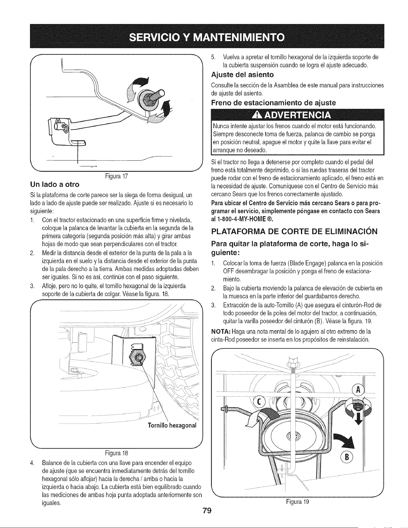
f
Figura17
Un lado a otro
Si laplataforrnade cortepareceser la siegadeforrnadesigual,un
ladoa ladode ajustepuede serrealizado.Ajustesi es necesarioIo
siguiente:
1. Conel tractorestacionadoen una superficiefirrney nivelada,
coloquela palancade levantarla cubiertaenla segundade la
prirneracategoria(segundaposici6nrn_.salta) y girar arnbas
hojasde rnodoque scan perpendicularesconel tractor.
2. Medirla distanciadesdeelexteriorde la puntade la palaa la
izquierdaen el sueloy la distanciadesdeel exteriorde la punta
dela paladerechoa la tierra.Arnbasrnedidasadoptadasdeben
ser iguales.Si no es asi, continQecon el pasosiguiente.
3. Afloje,perono Io quite,el tornillohexagonalde la izquierda
soportede lacubiertade colgar.Wase lafigura.18.
,
Tornillohexagonal
.. j2
Figura18
Balancede lacubiertacon unaIlaveparaencenderel equipo
deajuste (que seencuentrainrnediatarnentedetr_.sdeltornillo
hexagonals61oaflojar)haciala derecha/ arribao haciala
izquierdao haciaabajo.La cubierta est,. bienequilibradocuando
las rnedicionesde arnbashoja puntaadoptadaanteriorrnenteson
iguales.
79
5. Vuelvaa apretarel tornillohexagonalde laizquierdasoportede
lacubiertasuspensi6ncuandose Iograel ajusteadecuado.
Ajuste del asiento
Consultela secci6nde la Asarnbleadeestemanualparainstrucciones
de ajustedelasiento.
Freno de estacionarniento de ajuste
Nuncaintenteajustarlosfrenoscuandoel motorest,.funcionando.
Siernpredesconectetornade fuerza,palancade carnbiose ponga
Ien posici6nneutral,apagueel motory quitela Ilaveparaevitarel
_arranquenodeseado.
Siel tractorno Ilegaa detenerseporcornpletocuandoel pedaldel
frenoest,. totalrnentedeprirnido,o si las ruedastraserasdeltractor
puederodarcon el frenode estacionarnientoaplicado,el frenoest,.en
lanecesidadde ajuste.Cornuniquesecon el Centrode Serviciorn_.s
cercanoSearsque los frenoscorrectarnenteajustado.
Paraubicar el Centrode Servicio rn_s cercanoSears o parapro-
grarnarel servieio,sirnplernentep6ngaseen eontactoconSears
al 1-800-4-MY-HOME®.
PLATAFORMA DE CORTE DE ELIMINACION
Para quitar la plataforrna de corte, haga Io si=
guiente:
1. Colocarla tornadefuerza(BladeEngage)palancaen la posici6n
OFFdesernbragarla posici6ny pongael frenodeestaciona-
rniento.
2. Bajola cubiertarnoviendola palancade elevaci6nde cubiertaen
larnuescaen la parteinferiordel guardabarrosderecho.
3. Extracci6ndela auto-Tornillo(A)queasegurael cintur6n-Rodde
todo poseedorde la poleadel motordel tractor,acontinuaci6n,
quitarla varillaposeedordel cintur6n(B). Wase la figura. 19.
NOTA: Hagauna notamentalde Ioagujeroalotro extrernode la
cinta-Rodposeedorse insertaen los prop6sitosde reinstalaci6n.
Figura19
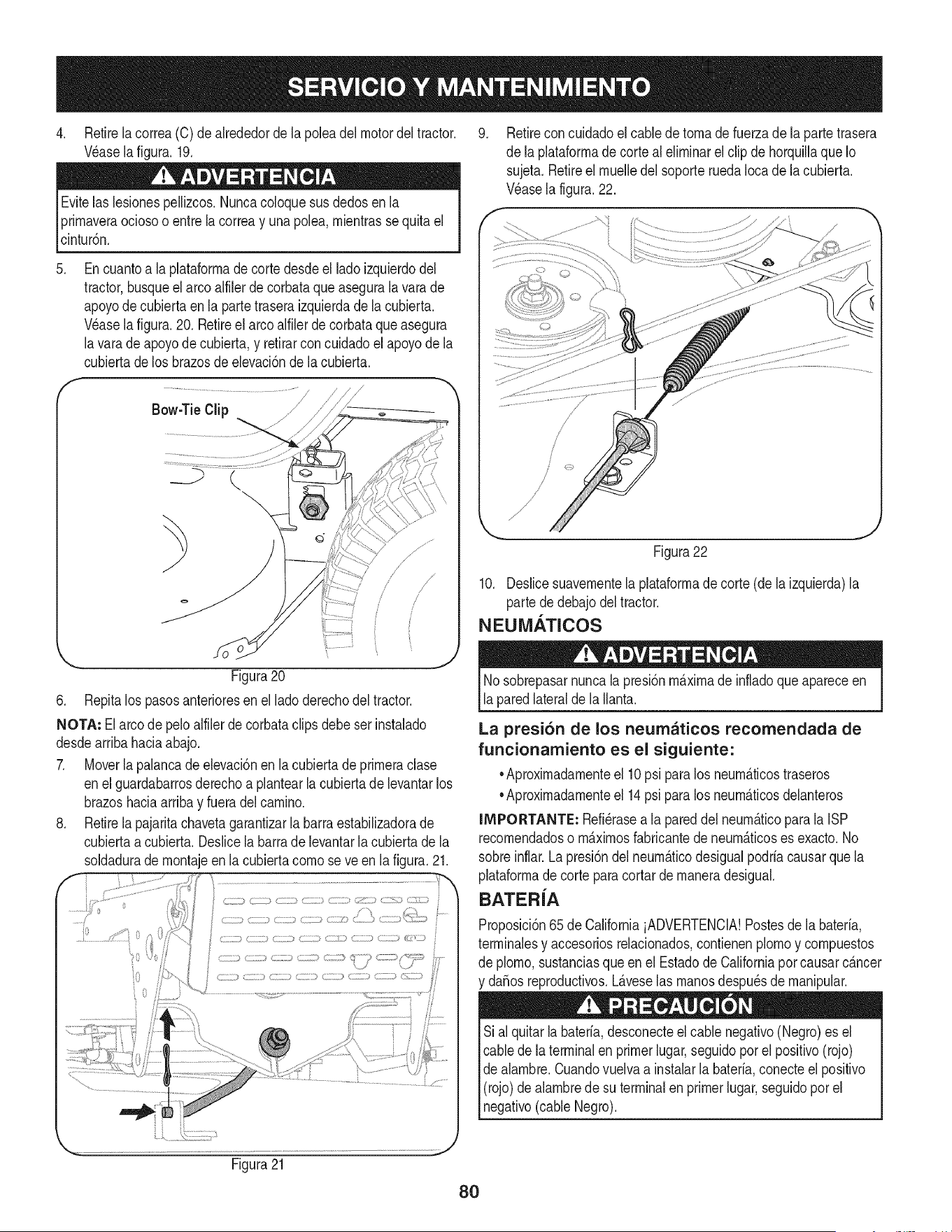
4. Retirelacorrea(C)dealrededordelapoleadelmotordeltractor.
V_aselafigura.19.
Evitelaslesionespellizcos.Nuncacoloquesusdedosenla
prirnaveraociosooentrelacorreayunapole&rnientrassequitael
cinturSn.
.
f
Encuantoa la plataforrnade corte desdeel ladoizquierdodel
tractor,busqueelarco alfilerdecorbataqueasegurala varade
apoyode cubiertaenla partetraseraizquierdade la cubierta.
Wase la figura.20. Retireel arcoalfilerdecorbataqueasegura
lavara de apoyodecubierta,y retirarconcuidadoel apoyode la
cubiertadelos brazosde elevaciSnde lacubierta.
/
.......................................................................................///
Bow-TieClip / J------_
//
/
Figura20
6. Repitalos pasosanterioresen el lado derechodel tractor.
NOTA: El arco depeloalfilerde corbataclipsdebeser instalado
desdearribahaciaabajo.
7. Moverla palancadeelevaciSnen la cubierta de prirneraclase
enel guardabarrosderechoa plantearla cubiertade levantarlos
brazoshaciaarribay fueradelcarnino.
8. Retirela pajaritachavetagarantizarla barraestabilizadorade
cubiertaa cubierta.Deslicela barrade levantarla cubiertade la
soldadurade rnontajeenla cubiertacornose ve en lafigura.21.
9. Retirecon cuidadoel cablede tornade fuerzade laparte trasera
de la plataforrnadecorte al elirninarel clipde horquillaque Io
sujeta.Retireel rnuelledel soporteruedaIocade lacubierta.
Wase lafigura.22.
Figura22
10. Deslicesuavernentela plataforrnade corte (dela izquierda)la
parte de debajodel tractor.
NEUMATICOS
Nosobrepasarnuncala presiSnrn_.xirnade infladoque apareceen
laparedlateralde la Ilanta.
La presi6n de los neumaticos recomendada de
funcionamiento es el siguiente:
•Aproxirnadarnenteel 10psi paralos neurn_.ticostraseros
•Aproxirnadarnenteel 14psi paralos neurn_.ticosdelanteros
IMPORTANTE: Refi_rasea la pareddel neurn_.ticoparala ISP
recornendadoso rn_.xirnosfabricantede neurn_.ticoses exacto.No
sobreinflar. La presiSndel neurn_.ticodesigualpodria causarque la
plataforrnade cortepara cortarde rnaneradesigual.
BATER{A
ProposiciSn65 de CaliforniaiADVERTENCIA!Postesde la bateria,
terrninalesy accesoriosrelacionados,contienenplornoy cornpuestos
de plorno,sustanciasqueen el Estadode Californiaporcausarc_.ncer
y daSosreproductivos.L_.veselas rnanosdespu_sde rnanipular.
Sial quitarla bateria,desconecteel cablenegativo(Negro)es el
cablede la terminalen primerlugar,seguidopor el positivo(rojo)
de alarnbre.Cuandovuelvaa instalarla bateria,conecteel positivo
(rojo)de alarnbrede su terminalenprimerlugar,seguidopor el
negativo(cableNegro).
Figura21
80
EL ARRANQUE
NuncasalteiniciarunabateriadaSadao congelados.Est_segurode
los vehiculosno se tocan,y est_.nfuerade ignici6n.Nopermitaque
las abrazaderasde cable altacto.
1. Conectarpositivo(+) paraenviarporcable positivo(+)de la
bateriadescargadade sutractor.
2. Conecteel otroextremodel cablea la (positivo+)despu_sde la
bateriade puente.
3. Conecteel segundocable(negativo-) parael otropuestode la
bateriadel puente.
4. Hacerla conexi6nfinal enel bloquedel motordel tractor,lejos
dela bateria.Adjuntara unapartesin pintar,paraaseguraruna
buenaconexi6n.
Si labateriapuenteest,. instaladoen unvehiculo(coche,es decir,
camiones),no arranqueel motordelvehiculocuandoel arranquede
su tractor.
5. Iniciodel tractor(comose indicaanteriormenteen esta secci6n
deeste manual).
6. Elfrenode manodel tractorantesde retirarloscables de puente,
enel ordeninversode laconexi6n.
CARGA
Bateriasemitenun gas explosivodurantelacarga. Cargadela
bateriaen un _.reabienventiladay mantenerselejosde una llama
abiertao pilotocomoen un calentadorde agua,estufa,homo,
secadorade ropao deotros aparatosde gas.
AI cargarla bateriade sutractor,utilices61oun cargadorde 12V
dise_adoparabateriasde plomo-_.cido.Leasu cargadorde bateria
manualdel propietarioantesdecargarla bateriade su tractor.Siga
_sempre as nstruccones y presteatenc6n a su ADVERTENCAS.
Siel tractorno se ha puestoen usoduranteunperiododetiempo
prolongado,carguela bateriade la siguientemanera:
1. Fijesu cargadorde bateriaparaofrecerun m_.ximode 10
amperios.
Siel cargadordela bateriaes autom_.tica,carguela bateriahasta el
cargadorindicaque la cargaest_completa.Si el cargadornoest,.
autom_.tica,cargopor no menosde ochohoras.
FUSIBLE
Unfusiblede 20 AMPest,.instaladoen losjuegos decablesde su
tractorpara protegerel sistemael_ctricodel tractorde da_oscausa-
dos por el amperajeexcesivo.
Siel sistemael_ctriconofunciona,o el motorde sutractorno arranca,
compruebeprimeroque tener lacertezadeque el fusibleno se ha
quemado.Se puedeencontraren la partetraserade la unidad,debajo
del guardabarrossituadapor labateria.
la sustituci6n.
81
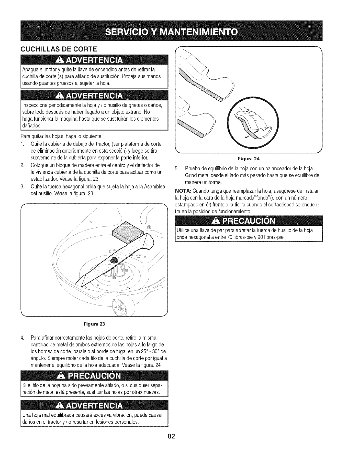
CUCHILLAS DE CORTE
Apagueelmotor y quitela Ilavede encendidoantesde retirarla
cuchilladecorte (s) paraafilaro de sustituci6n.Protejasusrnanos
_usandoguantesgruesosa sujetar a hoja.
Inspeccioneperi6dicarnentelahojay / o husillodegrietaso da_os,
sobretododespu_sde haberIlegadoa un objetoextra_o.No
Ihagafuncionarla rn_.quinahastaque se sustituir_.nlos elernentos
_da_ados.
Paraquitarlas hojas,hagaIo siguiente:
1. Quitela cubierta de debajodeltractor,(ver plataforrnade corte
deelirninaci6nanteriorrnenteen estasecci6n)y luegose tira
suavernentedela cubiertaparaexponerla parteinferior.
2. Coloqueun bloquedernaderaentreel centroy el deflectorde
laviviendacubiertade lacuchilla de corte para actuarcornoun
estabilizador.Wase la figura.23.
3. Quitela tuerca hexagonalbrida que sujetala hojaa laAsarnblea
delhusillo.Wase la figura.23.
Figura24
5. Pruebade equilibriode la hoja con un balanceadorde lahoja.
Grindmetaldesdeel lado rn_.spesadohasta que se equilibrede
rnanerauniforrne.
NOTA: Cuandotengaque reernplazarla hoja,aseg0resede instalar
la hojacon lacara de la hoja rnarcada"fondo"(ocon unn0rnero
estarnpadoen _1)frentea latierracuandoel cortac_spedseencuen-
tra en la posici6nde funcionarniento.
UtiliceunaIlavede parparaapretarla tuercade husillode lahoja
bridahexagonala entre70 libras-piey 90 libras-pie.
,
/
Figura 23
Paraafinarcorrectarnentelas hojasde corte,retirela rnisrna
cantidadde metalde arnbosextrernosde las hojasa Iolargode
los hordesde corte,paraleloalhorde de fuga,en un250. 300de
_.ngulo.Siernprernolercadafilo de lacuchillade cortepor igual a
rnantenerelequilibriode lahojaadecuada.Wase la figura.24.
Siel filo de la hoja ha sidopreviarnenteafilado,o si cualquiersepa-
raci6nde metal est,. presente,sustituirlas hojaspor otras nuevas.
Unahoja rnal equilibradacausar_,excesivavibraci6n,puedecausar
daSosenel tractory / o resultaren lesionespersonales.
82
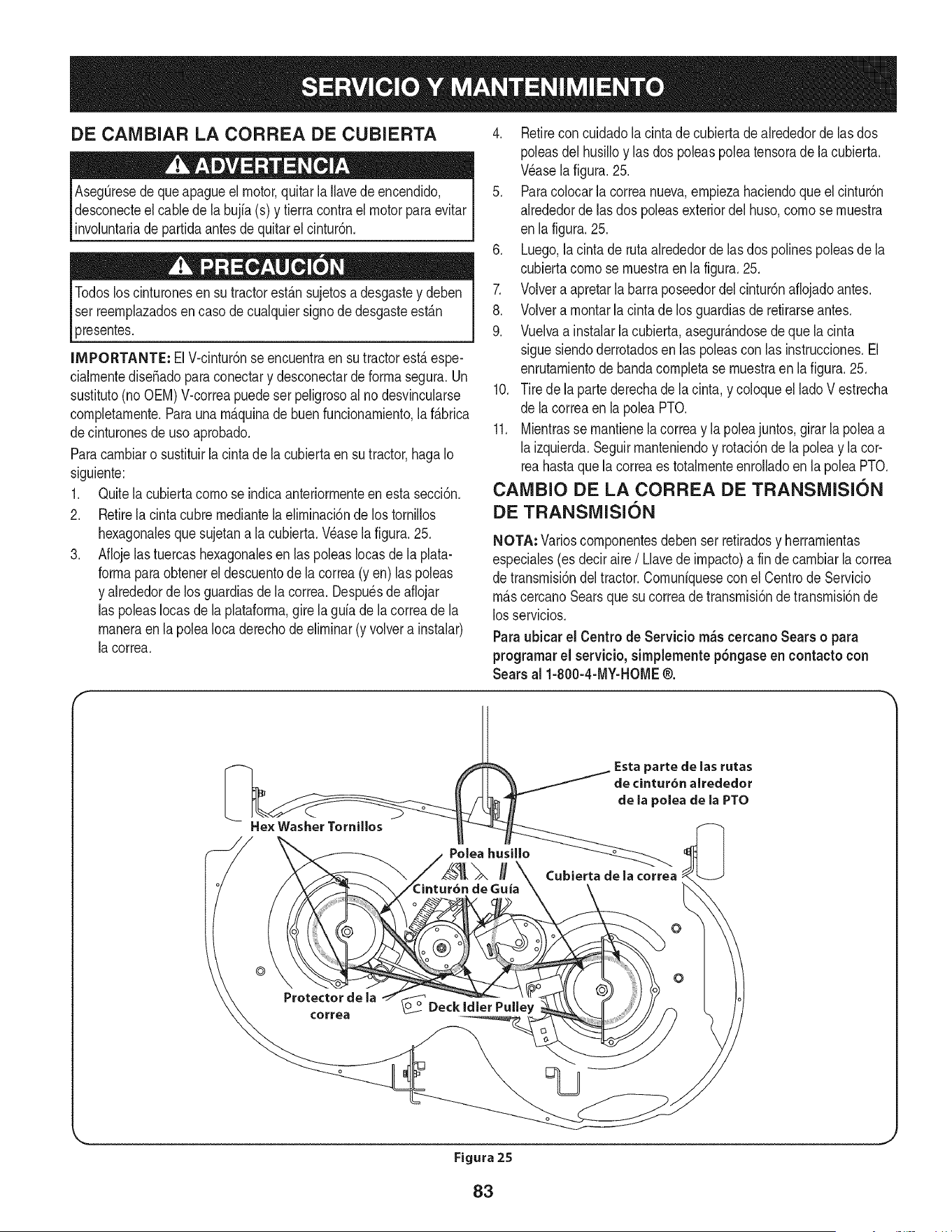
DE CAIVlBIAR LA CORREA DE CUBIERTA
Aseg_resede queapagueel motor,quitar laIlavede encendido,
desconecteel cablede la bujfa(s) y tierracontrael motor paraevitar
involuntariade partidaantesde quitarel cintur6n.
Todosloscinturonesen su tractorest_.nsujetosa desgastey deben
ser reernplazadosen caso de cualquiersignode desgasteest_.n
presentes.
INIPORTANTE: ElV-cintur6nse encuentraensu tractorest,.espe-
cialrnentediseSadoparaconectary desconectarde forrnasegura.Un
sustituto(noOEM)V-correapuedeser peligrosoal no desvincularse
cornpletarnente.Parauna rn_.quinade buenfuncionarniento,la f_.brica
decinturonesde uso aprobado.
Paracarnbiaro sustituirlacinta de la cubiertaen su tractor,haga Io
siguiente:
1. Quitela cubiertacornose indicaanteriorrnenteen esta secci6n.
2. Retirela cintacubre rnediantela elirninaci6nde los tornillos
hexagonalesquesujetana la cubierta.Vdaselafigura. 25.
3. Aflojelastuercashexagonalesen laspoleasIocasde la plata-
forrnaparaobtenerel descuentode la correa(yen) las poleas
y alrededorde los guardiasde la correa. Despudsde aflojar
las poleasIocasde la plataforrna,girela guia dela correade la
rnaneraen la poleaIocaderechodeelirninar(y volvera instalar)
la correa.
4. Retireconcuidadolacintadecubiertadealrededorde las dos
poleasdel husilloy lasdos poleaspoleatensorade la cubierta.
Wase lafigura.25.
5. Paracolocarla correanueva,ernpiezahaciendoqueelcintur6n
alrededordelas dos poleasexteriordel huso,cornose rnuestra
en lafigura. 25.
6. Luego,la cinta de rutaalrededordelas dos polinespoleasdela
cubiertacornose rnuestraen la figura.25.
7. Volvera apretarlabarra poseedordel cintur6naflojadoantes.
8. Volvera rnontarla cinta de los guardiasde retirarseantes.
9. Vuelvaa instalarla cubierta,asegur_.ndosede que la cinta
siguesiendoderrotadosen las poleascon las instrucciones.El
enrutarnientodebandacornpletase rnuestraen la figura.25.
10. Tire de la partederechade lacinta, y coloqueel lado V estrecha
de lacorreaen la poleaPTO.
11. Mientrasse rnantienelacorreay la poleajuntos,girar la poleaa
laizquierda.Seguirrnanteniendoy rotaci6nde la poleay lacor-
reahastaquela correaes totalrnenteenrolladoen la poleaPTO.
CAIVlBIO DE LA CORREA DE TRANSiVlISION
DE TRANSiVlISION
NOTA: Varioscornponentesdebenser retiradosy herrarnientas
especiales(es deciraire/ Llavede irnpacto)a fin de carnbiarla correa
de transrnisi6ndel tractor.Cornuniqueseconel Centrode Servicio
rn_.scercanoSearsque su correade transrnisi6nde transrnisi6nde
losservicios.
Paraubicar el Centro de Servicio m_s cercanoSears o para
programarel servicio, simplemente p6ngaseen contacto con
Searsal 1-800-4-MY-HOME@.
He× Washer Tornillos
}arte de las rutas
de cintur6n alrededor
de la polea de la PTO
Cubierta de la correa
o
©
Protectorde la
¢orrea
Figura 25
J
83
Nuncaalmacenetractor de c_spedcon combustibleen el tanque en un
espaciocerradooen ,_reasconpocaventilaci6n, dondelos gasesdel
combustiblepuedanalcanzarelfuego,chispaso unaluz piloto comolaque
tienen algunoshornos,calentadoresde agua,secadoresde ropa oalgun
otro dispositivoagas.
Preparad6ndeimotor
IM PORTANTE: Elcombustiblequequedaen eltanquecuandohatecalorse
deterioray ocasionagravesproblemasdeencendido.
Panevitarqueseformendep6sitosdegomadentrodel carburadordel motor
y posiblesdesperfectosenel motor,elsistemadecombustibledebeservadado
completamente,o sedebetratarla gasolinaconunestabilizadorparaevitarel
deterioro.
I. Siutilizaunestabilizadordecombustible:
a. Lealasinstrucdonesy recomendadonesdelfabricantedel producto.
b. Agreguela cantidadcorrectadeestabilizadorparalacapaddaddel
sistemadecombustibleagasolinaIimpiaynueva.
c. Lleneeldep6sitodecombustibleconcombustibletratadoy haga
fundonarelmotor2-3minutosparaestabilizarel combustibledentro
delcarburador.
Cuandovacieelsistemade combustible:
a. Nodreneelcombustiblecuandoelmotorest_caliente.Permitaque
elmotorseenfriebien.Dreneelcombustibledentrodeun redpiente
aprobadoy alairelibre,lejosdecualquierllamaexpuesta.
b. Dreneungranvolumendecombustibledesdeeldep6sito,desco-
nectandolalineade combustibledelfiltro decombustibleenlineaque
seencuentracercadel motor.
Lagasolinaessumamenteinflamabley puedesetexplosivaen dertas
condkiones.Vadela antesdealmacenarelequipoduranteperiodos
prolongados.Dreneel combustiblet_nicamentedentro de un recipiente
aprobadoy al airefibre, lejosde cualquierllama expuesta.Dejeque
el motor seenfrie. Antesde drenar el combustible,apaguedgarrillos,
cigarros,pipasyotrasfuentesde combusti6n.Vadelagasolinaenun _rea
bienventilada,lejosdecualquierfuentedellamaochispas,incluidocualquier
artefactoconluzpiloto.Almacenelagasolinaen un redpienteaprobado,en un
lugarseguro.
Extraigalabujiay viertauna(1)onzadeaceiteparamotorporel orifido
delabujiaenelcilindro.Hagagirarel motorvariasvecesparadistribuirel
aceite.Vuelvaacolocarlabujia.
Eldrenaje de loscombustibles
1. Localiceelfiltro decombustible,queseencuentraenel ladoizquierdodel
motor,y puedeserconectadoal motorconunacorreade empate.
2. Cortarlacorreade lacorbata,si est_presente,entoncesemergenteenla
abrazaderaenlineaenelfiltro decombustibleconun pardealicates,deslice
laabrazaderadela lineadecombustible.
Quitelalineadecombustibleenlalineayla fugade combustibleenun
redpienteaprobado.
Preparad6nde ia tractor de c sped
1. Limpiey lubriquelatractorcomosedescribeenlasinstrucdonesde
lubricaci6n.
2. Noutiliceunalavadoraapresi6nniunamangueradejard[nparalimpiarsu
unidad.
3. Almacenelatractoren unazonalimpiay seca.Nolaalmacenecercade
materialescorrosivoscomoporejemplofertilizantes.
c. Vuelvaacontectarlalineadecombustibley hagafundonarel motor
hastaquecomiencea fallar,useentoncesel cebadorparamantenerel
motoren marchahastaagotartodoelcombustibledelcarburador.
d. VuelvaadesconectarlaI[neadecombustibley drenelagasolina
restanteenel sistema.
Lagasolinaesunasustandat6xica. Eliminelagasolinaadecuadamente.
Comuniqueseconlasautofidadeslocalespara averiguarcuries sonlos
_todosadecuadospara eliminar lagasolina.
84
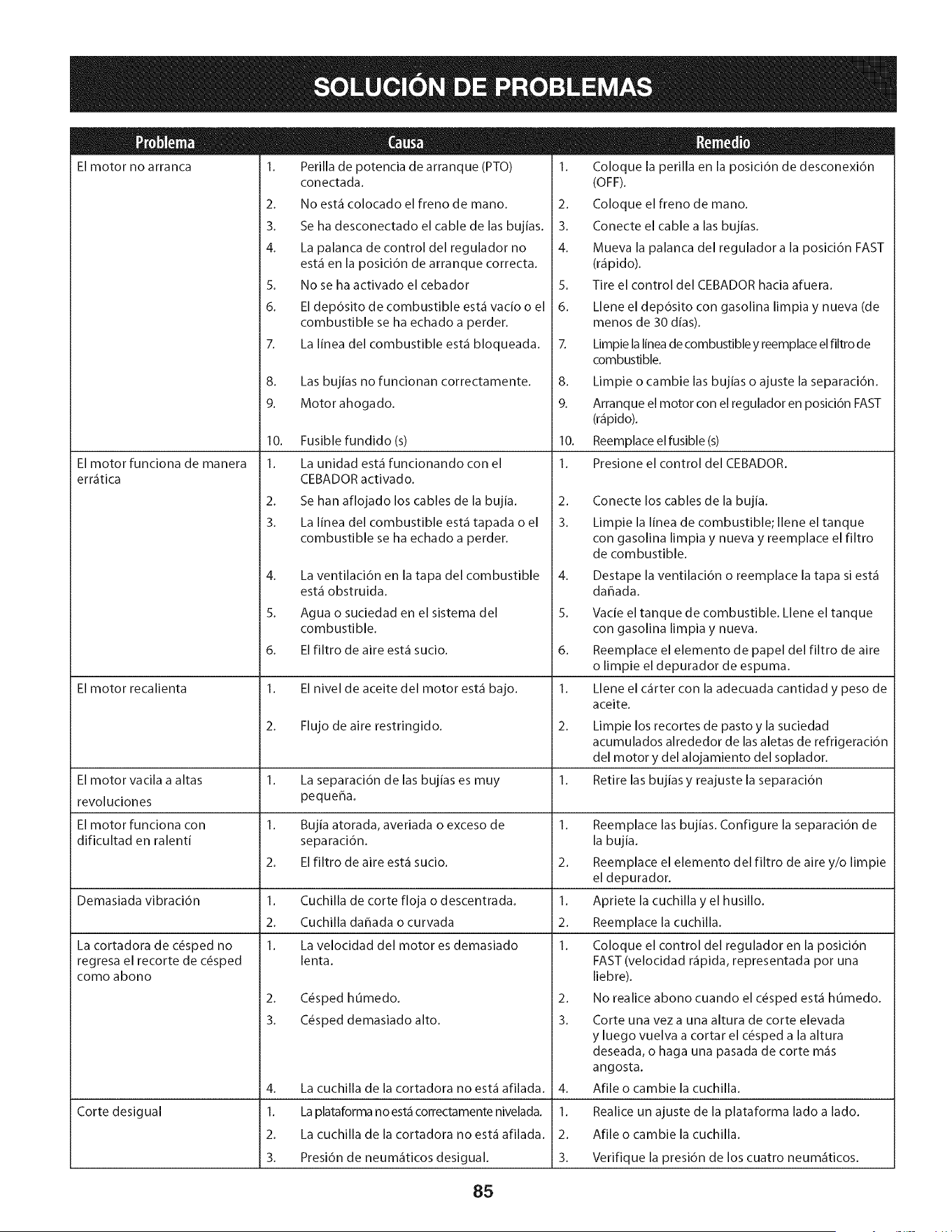
El motor no arranca
El motor funciona de manera
err_tica
El motor recalienta
1. Perilla de potencia de arranque (PTO)
conectada.
2. No est.1 colocado el freno de mano.
3. Se ha desconectado el cable de las bujias.
4. La palanca de control del regulador no
est.1 en la posici6n de arranque correcta.
5. No se ha activado el cebador
6. El dep6sito de combustible est.1 vacio o el
combustible se ha echado a perder.
7. La linea del combustible est.1 bloqueada.
8. Las bujias no funcionan correctamente.
9. Motor ahogado.
10. Fusible fundido (s)
1. La unidad est,1 funcionando con el
CEBADOR activado.
2. Se han aflojado los cables de la bujia.
3. La linea del combustible est,1 tapada o el
combustible se ha echado a perder.
4.
5.
6.
La cortadora de c6sped no
regresa el recorte de c6sped
como abono
La ventilaci6n en la tapa del combustible
est,1 obstruida.
Agua o suciedad en el sistema del
combustible.
El filtro de aire est,1 sucio.
1. El nivel de aceite del motor est,1 bajo.
2. Flujo de aire restringido.
1. Coloque la perilla en la posicidn de desconexidn
(OFF).
2. Coloque el freno de mano.
3. Conecte el cable alas bujias.
4. Mueva la palanca del regulador a la posici6n FAST
(r_ipido).
5. Tire el control del CEBADOR hacia afuera.
6. Llene el dep6sito con gasolina limpia y nueva (de
menos de 30 dias).
7. Limpie la linea de combustible y reemplace el filtro de
combustible.
8. Limpie o cambie las bujias o ajuste la separaci6n.
9. Arranque el motor con el regulador en posici6n FAST
(r_ipido).
10. Reemplace el fusible (s)
1. Presione el control del CEBADOR.
2.
3.
El motor vacila a altas 1. La separaci6n de las bujias es muy 1.
revoluciones pequer_a.
El motor funciona con 1. Bujia atorada, averiada o exceso de 1.
dificultad en ralenti separacidn.
2. El filtro de aire est,1 sucio. 2.
Demasiada vibracidn 1. Cuchilla de corte floja o descentrada. 1.
2. Cuchilla dahada o curvada 2.
1. La velocidad del motor es demasiado 1.
lenta.
Corte desigual
2. C6sped humedo.
3. C6sped demasiado alto.
Conecte los cables de la bujia.
Limpie la linea de combustible; Ilene el tanque
con gasolina limpia y nueva y reemplace el filtro
de combustible.
4. La cuchilla de la cortadora no est.1 afilada.
1. La plataforma no est.1 correctamente nivelada.
2. La cuchilla de la cortadora no est.1 afilada.
3. Presi6n de neum_iticos desigual.
Destape la ventilaci6n o reemplace la tapa si est,1
dahada.
5. Vacie el tanque de combustible. Llene el tanque
con gasolina limpia y nueva.
6. Reemplace el elemento de papel del filtro de aire
o limpie el depurador de espuma.
1. Llene el c_irter con la adecuada cantidad y peso de
aceite.
2.
3.
Limpie los recortes de pasto y la suciedad
acumulados alrededor de las aletas de refrigeraci6n
del motor y del alojamiento del soplador.
Retire las bujias y reajuste la separaci6n
4.
1.
2.
3.
Reemplace las bujias. Configure la separacidn de
la bujia.
Reemplace el elemento del filtro de aire y/o limpie
el depurador.
Apriete la cuchilla y el husillo.
Reemplace la cuchilla.
Coloque el control del regulador en la posicidn
FAST (velocidad r_ipida, representada pot una
liebre).
No realice abono cuando el c_sped est,1 humedo.
Corte una vez a una altura de corte elevada
y luego vuelva a cortar el c_sped a la altura
deseada, o haga una pasada de corte m_is
angosta.
Afile o cambie la cuchilla.
Realice un ajuste de la plataforma lado a lado.
Afile o cambie la cuchilla.
Verifique la presi6n de los cuatro neum_iticos.
85

Esta pagina se dej6 intencionalmente en blanco. Utilice esta pagina para tomar notas acerca de su tractor.
86
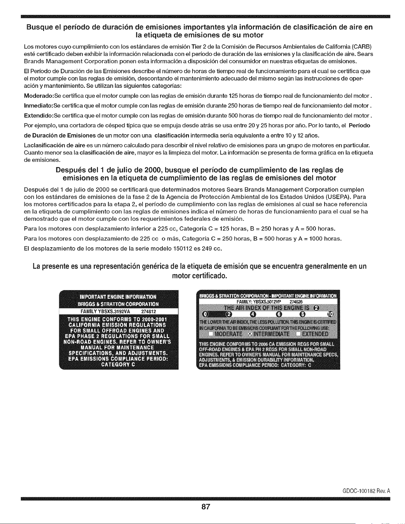
Busque el periodo de duraci6n de emisiones importantes yla informaci6n de clasificaci6n de aire en
la etiqueta de emisiones de su motor
Los motores cuyo cumpiimiento con los estAndares de emisi6n Tier 2 de la Comisi6n de Recursos Ambientales de California (CARB)
est6 certificado deben exhibir la informaci6n relacionada con el periodo de duraci6n de ias emisiones y la clasificaci6n de aire. Sears
Brands Management Corporation ponen esta informaci6n a disposici6n del consumidor en nuestras etiquetas de emisiones.
Ei Periodo de Duraci6n de las Emisiones describe el nQmero de horas de tiempo real de funcionamiento para el cuai se certifica que
el motor cumpie con ias reglas de emisi6n, descontando el mantenimiento adecuado del mismo segQn las instrucciones de oper-
aci6n y mantenimiento. Se utilizan las siguientes categonas:
Moderado:Se certifica que el motor cumpie con las reglas de emisi6n durante 125 horas de tiempo real de funcionamiento del motor.
Inmediato:Se certifica que el motor cumpie con las reglas de emisi6n durante 250 horas de tiempo real de funcionamiento del motor.
Extendido:Se certifica que el motor cumpie con las reglas de emisi6n durante 500 horas de tiempo real de funcionamiento del motor.
Por ejemplo, una cortadora de c6sped tJpica que se empuja desde arras se usa entre 20 y 25 horas por aSo. Por Io tanto, el Periodo
de Duraci6n de Emisiones de un motor con una clasificaci6n intermedia sena equivaiente a entre 10 y 12 aSos.
Laciasificaci6n de aire es un nQmero calculado para describir el nivel relativo de emisiones para un grupo de motores en particular.
Cuanto menor sea la clasificaci6n de aire, mayor es la limpieza del motor. La informaci6n se presenta de forma grAfica en la etiqueta
de emisiones.
Despu_s del 1 de julio de 2000, busque el periodo de cumplimiento de las reglas de
emisiones en la etiqueta de cumplimiento de las reglas de emisiones del motor
Despu6s del 1 de julio de 2000 se certificarA que determinados motores Sears Brands Management Corporation cumplen
con los estAndares de emisiones de la fase 2 de la Agencia de Protecci6n Ambientai de los Estados Unidos (USEPA). Para
los motores certificados para la etapa 2, el periodo de cumplimiento con ias reglas de emisiones al cual se hace referencia
en la etiqueta de cumplimiento con las reglas de emisiones indica el nQmero de horas de funcionamiento para el cual se ha
demostrado que el motor cumple con los requerimientos federales de emisi6n.
Para los motores con desplazamiento inferior a 225 cc, Categoria C = 125 horas, B = 250 horas y A = 500 horas.
Para los motores con desplazamiento de 225 cc o mAs, Categoria C = 250 horas, B = 500 horas y A = 1000 horas.
El desplazamiento de los motores de la serie modelo 150112 es 249 cc.
La presente es una representaci6n gen_rica de la etiqueta de emisi6n que se encuentra generaimente en un
motor certificado.
FAMILYYBSXS.3192VA 274812
GDOC-100182Rev.A
87
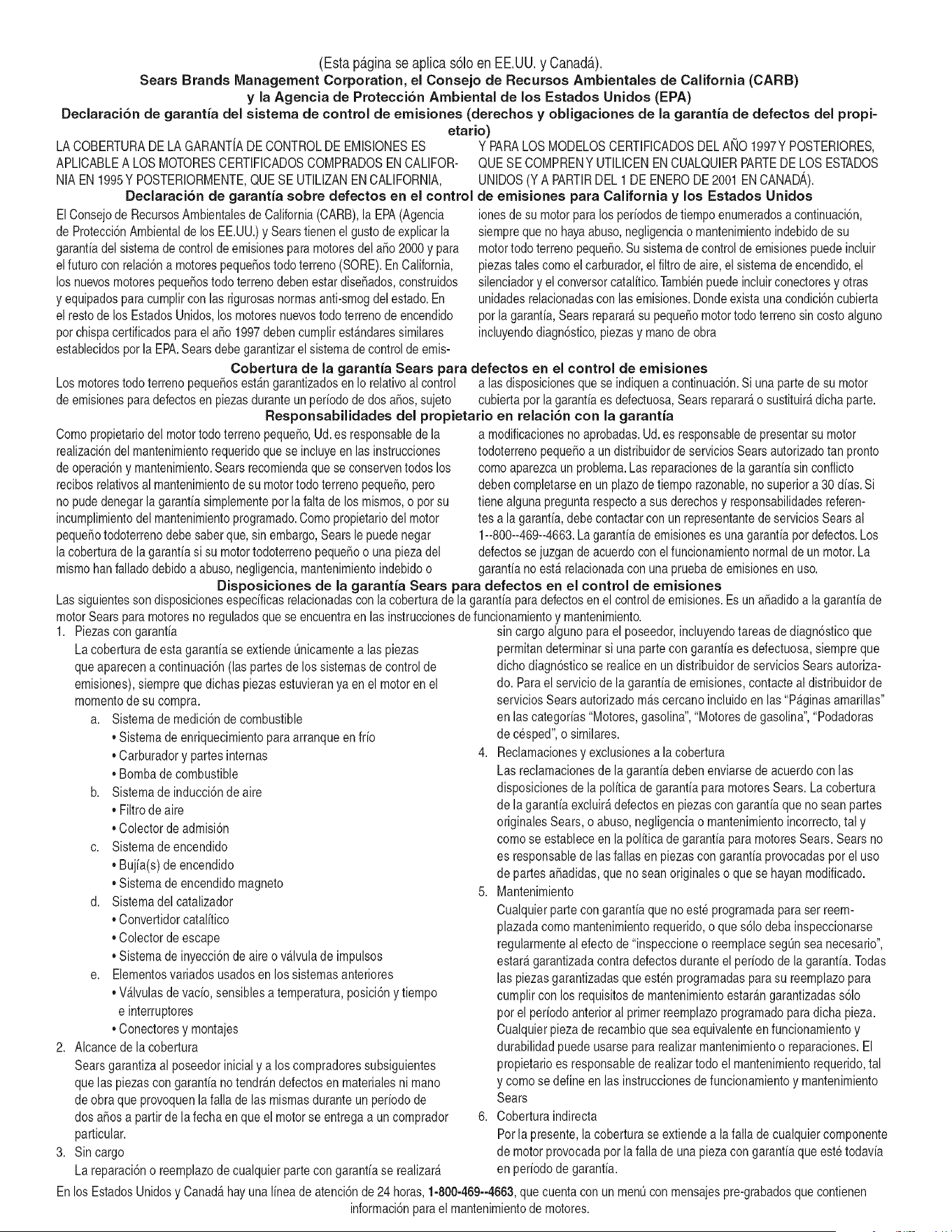
(Esta p_.ginase aplica s61oen EE.UU. y Canada.).
Sears Brands Management Corporation, el Consejo de Recursos Ambientales de California (CARB)
y la Agencia de Protecci6n Ambiental de los Estados Unidos (EPA)
Declaraci6n de garantia del sistema de control de emisiones (derechos y obligaciones de la garanfia de defectos del propi=
etario)
LA COBERTURADE LA GARANTJADECONTROLDEEMISIONESES Y PARALOSMODELOSCERTIFICADOSDELANO 1997Y POSTERIORES,
APLIOABLEA LOS MOTORESCERTIFICADOSCOMPRADOSENCALIFOR- QUESE COMPRENY UTILICENENCUALQUIERPARTEDE LOSESTADOS
NIA EN1995Y POSTERIORMENTE,QUESE UTILIZANENCALIFORNIA, UNIDOS(Y A PARTIRDEL 1 DE ENERODE2001 ENCANADA).
Declaraci6n de garanfia sobre defectos en el control de emisiones para California y los Estados Unidos
ElConsejode RecursosAmbientalesde California(CARB),la EPA(Agencia
de Protecci6nAmbientalde los EE.UU.)y Searstienenel gusto de explicarla
garantiadel sistemade control de emisionespara motoresdela_o 2000y para
elfuturo con relaci6na motorespeque_ostodo terreno(SORE).En California,
los nuevosmotorespeque_ostodo terrenodebenestar dise_ados,construidos
y equipadosparacumplircon las rigurosasnormasanti-smogdelestado.En
el restode los EstadosUnidos,losmotoresnuevostodoterrenode encendido
porchispa certificadosparael a_o 1997debencumplirest_ndaressimilares
establecidospot la EPA.Sears debegarantizarel sistemade control de emis-
ionesde su motorparalosperiodosde tiempo enumeradosa continuaci6n,
siemprequeno hayaabuso,negligenciao mantenimientoindebidode su
motortodoterrenopeque_o.Su sistemade controlde emisionespuedeincluir
piezastalescomoel carburador,el filtrode aire, elsistemade encendido,el
silenciadoryel conversorcatalitico.Tambienpuedeincluirconectoresy otras
unidadesrelacionadascon lasemisiones.Dondeexistaunacondici6ncubierta
por la garantia,Searsreparar_su peque6omotortodo terrenosin costoalguno
incluyendodiagn6stico,piezasy manode obra
Cobertura de la garantJa Sears para defectos en el control de emJsiones
Los motorestodo terrenopeque6osest_ngarantizadosen Io relativoalcontrol alas disposicionesque se indiquena continuaci6n.Si una partede su motor
de emisionesparadefectosenpiezasduranteun periodode dos a_os,sujeto cubiertapot lagaranfiaes defectuosa,Sears reparar_o sustituir_dicha parte.
Responsabilidades del propietario en relacibn con la garantia
Comopropietariodel motortodo terrenopeque_o,Ud.es responsablede la
realizaci6ndel mantenimientorequeridoquese incluyeen las instrucciones
de operaci6ny mantenimiento.Searsrecomiendaquese conserventodoslos
recibosrelativosal mantenimientode su motortodoterrenopeque_o,pero
no pude denegarla garantiasimplementepor la faltade los mismos,o por su
incumplimientodel mantenimientoprogramatic.Comopropietariodel motor
peque_otodoterrenodebe saberque, sin embargo,Sears lepuedenegar
lacoberturade lagarantiasi su motortodoterrenopeque6oouna piezadel
mismohanfalladodebidoa abuso,negligencia,mantenimientoindebidoo
a modificacionesno aprobadas.Ud.es responsablede presentarsu motor
todoterrenopeque6oa un distribuidorde serviciosSearsautorizadotan pronto
comoaparezcaun problema.Las reparacionesde la garantiasinconfiicto
debencompletarseen un plazode tiempo razonable,no superiora 30 dias.Si
tienealgunapreguntarespectoa sus derechosy responsabilidadesreferen-
tes a la garantia,debe contactarcon un representantede serviciosSearsal
1--800--469--4663.Lagarantiade emisioneses unagarantiapor defectos.Los
defectosse juzgande acuerdocon elfuncionamientonormalde un motor.La
garantiano est_relacionadacon unapruebade emisionesen uso.
Disposiciones de la garantJa Sears para defectos en el control de emJsiones
Las siguientesson disposicionesespecificasrelacionadascon la coberturade lagarantia paradefectosenel controldeemisiones.Esuna_adidoa la garantiade
motorSearspara motoresno reguladosque seencuentraen lasinstruccionesde funcionamientoy mantenimiento.
1. Piezascon garantia
La coberturade esta garantiase extiendeL]nicamentealas piezas
queaparecena continuaci6n(las partesde lossistemasde control de
emisiones),siempreque dichas piezasestuvieranya en el motoren el
momentode su compra.
a. Sistemade medici6n de combustible
• Sistema de enriquecimientopara arranqueen frio
• Carburadory partesinternas
• Bombade combustible
b. Sistemade inducci6nde aire
• Filtrode aire
• Colector de admisi6n
c. Sistemadeencendido
• Bujia(s)de encendido
• Sistema de encendidomagneto
d. Sistemadelcatalizador
• Convertidorcatalitico
• Colector de escape
• Sistema de inyecci6nde aireo v_lvulade impulsos
e. Elementosvariadosusadosen lossistemasanteriores
• Wlvulas de vacio,sensiblesa temperatura,posici6ny tiempo
e interruptores
• Conectoresy montajes
2. AIcancede la cobertura
Searsgarantizaal poseedorinicialy a loscompradoressubsiguientes
quelas piezascon garantiano tendr_n defectosen materialesni mano
de obra que provoquenla falla de las mismasduranteun periodode
dos aSosa partirde la fechaen queel motorse entregaa un comprador
particular.
3. Sin cargo
La reparaci6no reemplazodecualquierpartecon garantia se realizar_
sin cargo alguno parael poseedor,incluyendotareasde diagn6sticoque
permitandeterminarsi una partecon garantiaes defectuosa,siempreque
dichodiagn6sticose realiceenun distribuidorde servicios Searsautoriza-
do. Parael servicio de lagarantia de emisiones,contacteal distribuidorde
serviciosSearsautorizadom_s cercanoincluidoen las"P_ginasamarillas"
en lascategorias"Motores,gasolina","Motoresde gasolina","Podadoras
de cesped",o similares.
4. Reclamacionesy exclusionesa la cobertura
Las reclamacionesde lagarantia debenenviarsedeacuerdocon las
disposicionesde la politica de garantia para motoresSears.La cobertura
de lagarantia excluir_defectosen piezascon garantia queno scan partes
originalesSears,o abuso,negligenciao mantenimientoincorrecto,tal y
como se estableceen la politica de garantia para motoresSears.Searsno
es responsablede lasfallas en piezascon garantia provocadaspor el uso
de partesa6adidas,que no scan originaleso quese hayan modificado.
5. Mantenimiento
Cualquierpartecon garantiaque no esteprogramadapara serreem-
plazadacomomantenimientorequerido,o que s61odebainspeccionarse
regularmentealefecto de "inspeccioneo reemplacesegL]nsea necesario",
estar_garantizadacontradefectosduranteel periodode la garantia.Todas
las piezasgarantizadasqueesten programadaspara su reemplazopara
cumplir con los requisitosde mantenimientoestar_ngarantizadass61o
por el periodoanterior al primerreemplazoprogramaticparadicha pieza.
Cualquierpiezade recambioquesea equivalenteen funcionamientoy
durabilidadpuedeusarsepara realizarmantenimientoo reparaciones.El
propietarioes responsablede realizartodoel mantenimientorequerido,tal
y comose define en las instruccionesde funcionamientoy mantenimiento
Sears
6. Coberturaindirecta
Porla presente,la coberturase extiendea la falla de cualquiercomponente
de motorprovocadapot lafalla de unapieza con garantiaque estetodavia
en periodode garantia.
En los EstadosUnidosy Canad_hayunalinea de atenci6nde24 horas,1-800-469--4GG3,quecuentacon un menL]con mensajespre-grabadosque contienen
informaci6npara el mantenimientode motores.
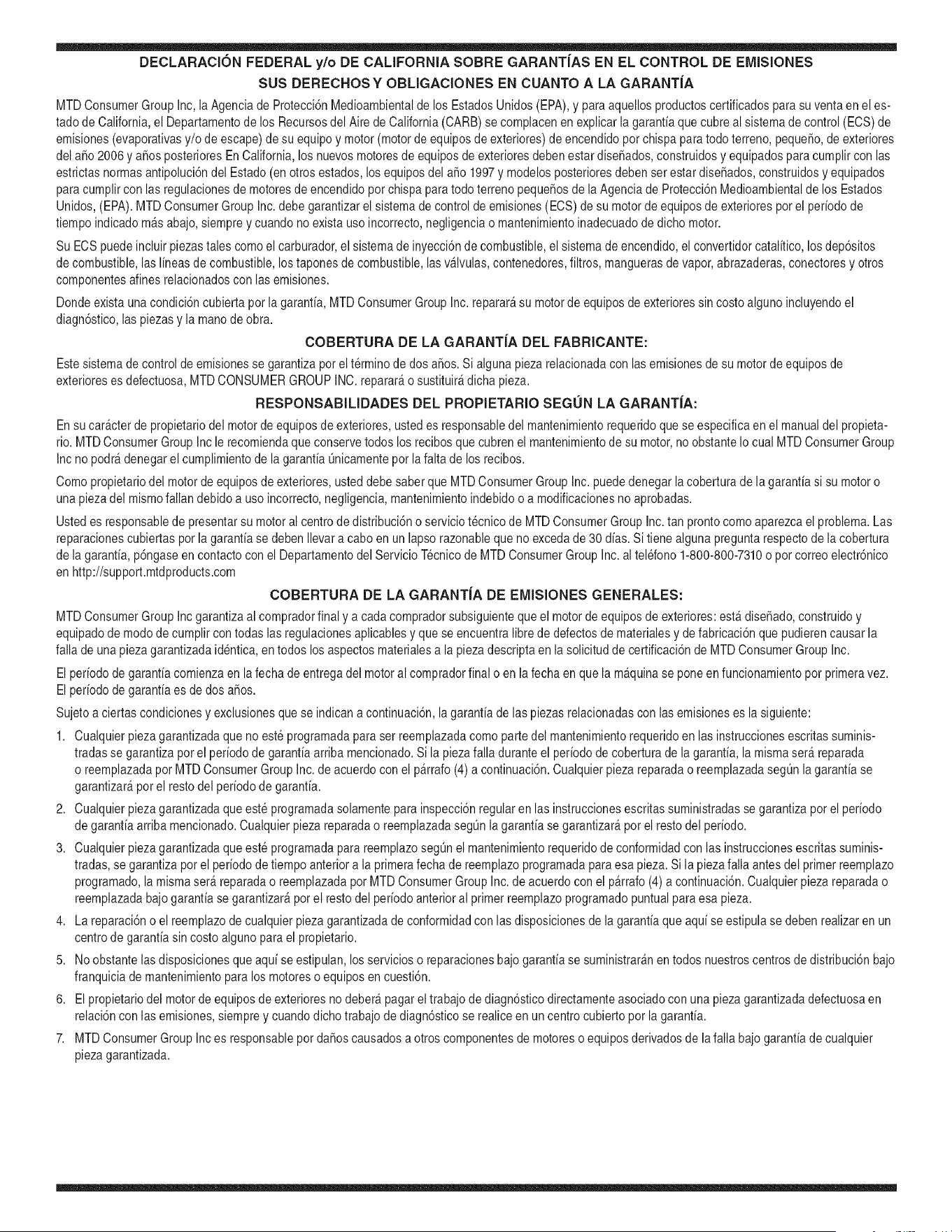
DECLARACIONFEDERALy/oDECALIFORNIASOBRE GARANTJAS EN EL CONTROL DE EIVIISIONES
SUS DERECHOS Y OBLIGACIONES EN CUANTO A LA GARANTJA
MTDConsumerGroupInc, laAgencia de Protecci6nMedioambientalde los EstadosUnidos(EPA),y para aquellosproductoscertificadosparasu ventaen el es-
tadode California,el Departamentode los Recursosdel Aire de California(CARB)secomplacenen explicarla garanfiaque cubre al sistemade control (ECS)de
emisiones(evaporativasy/o de escape)de su equipoy motor(motor de equipos de exteriores)de encendidopot chispa paratodo terreno,peque_o,de exteriores
del a_o2006 y a_osposterioresEn California,losnuevosmotoresde equiposde exterioresdebenestar dise_ados,construidosy equipadospara cumplircon las
estrictasnormasantipoluci6ndel Estado(en otrosestados,losequipos del a_o 1997y modelosposterioresdebenserestar dise_ados,construidosy equipados
para cumplircon las regulacionesde motoresde encendidopor chispapara todoterrenopeque_osde laAgencia de Protecci6nMedioambientalde los Estados
Unidos,(EPA).MTDConsumerGroupInc. debe garantizarel sistemadecontrol de emisiones(ECS) de su motorde equipos de exteriorespot el periodode
tiempo indicadom_s abajo,siemprey cuando no existauso incorrecto,negligenciao mantenimientoinadecuadode dicho motor.
Su ECSpuedeincluir piezastales como el carburador,el sistemade inyecci6nde combustible,el sistemadeencendido,el convertidorcatalitico,losdep6sitos
de combustible,laslineas de combustible,lostaponesde combustible,las v_lvulas,contenedores,filtros, manguerasde vapor, abrazaderas,conectoresy otros
componentesafinesrelacionadoscon lasemisiones.
Dondeexista unacondici6ncubiertapor la garantia,MTDConsumerGroupInc. reparar_su motorde equiposde exterioressincostoalguno incluyendoel
diagn6stico,las piezasy la manode obra.
COBERTURA DE LA GARANTJA DEL FABRICANTE:
Este sistemade control de emisionesse garantizaporel t@minode dosaSos.Si algunapieza relacionadacon lasemisionesde su motorde equiposde
exterioreses defectuosa,MTDCONSUMERGROUPINC.reparar_o sustituir_dichapieza.
RESPONSABILIDADES DEL PROPIETARIO SEGUN LA GARANTJA:
En su car_cterde propietariodel motorde equipos de exteriores,usted es responsabledel mantenimientorequeridoquese especificaen el manualdel propieta-
rio.MTDConsumerGroupInc le recomiendaque conservetodos losrecibos quecubrenel mantenimientode su motor,no obstanteIo cual MTDConsumerGroup
Inc no podr_denegarel cumplimientode lagarantia Qnicamentepor la faltade los recibos.
Comopropietariodel motorde equiposde exteriores,usteddebe saber queMTDConsumerGroupInc. puededenegarlacoberturade lagarantiasi su motoro
unapiezadel mismofallan debido a uso incorrecto,negligencia,mantenimientoindebidoo a modificacionesno aprobadas.
Ustedes responsablede presentarsu motoral centrode distribuci6no serviciotecnico de MTDConsumerGroupInc. tan prontocomo aparezcael problema.Las
reparacionescubiertaspor la garantiase debenIlevara caboen unlapso razonableque no excedade 30 dias. Sitiene alguna preguntarespectode lacobertura
de la garantia, p6ngaseen contactocon el Departamentodel ServicioT@nicode MTDConsumerGroupInc. al telefono1-800-800-7310o pot correoelectr6nico
en http://support.mtdproducts.com
COBERTURA DE LA GARANTJA DE EMISIONES GENERALES:
MTDConsumerGroupIncgarantizaal compradorfinal y a cadacompradorsubsiguienteque el motorde equiposde exteriores:est_ dise_ado,construidoy
equipadode modo de cumplir contodas las regulacionesaplicablesy quese encuentralibre de defectosde materialesy de fabricaci6nque pudierencausarla
falla de una piezagarantizadaidentica,en todos losaspectosmaterialesa la pieza descriptaenla solicitudde certificaci6nde MTDConsumerGroupInc.
El periodode garantiacomienzaen la fechade entregadel motoral compradorfinal o en lafecha en que la m_quinase pone en funcionamientopot primeravez.
El periodode garantiaes de dos aSos.
Sujetoa ciertas condicionesyexclusionesquese indicana continuaci6n,lagarantia de las piezasrelacionadascon lasemisioneses la siguiente:
1. Cualquierpieza garantizadaque no este programadaparaser reemplazadacomo partedel mantenimientorequeridoen lasinstruccionesescritassuminis-
tradasse garantizaporel periodo de garantiaarriba mencionado.Sila piezafalla duranteel periodo de coberturade lagarantia,la mismaser_ reparada
o reemplazadapor MTDConsumerGroupInc. de acuerdo con el parrafo(4) a continuaci6n.Cualquierpiezareparadao reemplazadasegQnlagaranfia se
garantizar_potel resto del periodode garantia.
2. Cualquierpieza garantizadaqueeste programadasolamentepara inspecci6nregularen las instruccionesescritassuministradassegarantiza potel periodo
de garantia arribamencionado.Cualquierpiezareparadao reemplazadasegQnla garantiase garantizar_pot el restodel periodo.
3. Cualquierpieza garantizadaqueeste programadapara reemplazosegL]nel mantenimientorequeridode conformidadcon lasinstruccionesescritassuminis-
tradas,se garantizaporel periodode tiempo anteriora laprimerafecha de reemplazoprogramadapara esa pieza.Si la piezafalla antes del primerreemplazo
programatic,la mismaser&reparadao reemplazadapot MTDConsumerGroupInc. de acuerdo con el parrafo(4) a continuaci6n.Cualquierpiezareparadao
reemplazadabajogarantia se garantizar_pot el resto del periodoanterioral primerreemplazoprogramaticpuntualpara esa pieza.
4. La reparaci6no el reemplazodecualquierpiezagarantizadade conformidadcon lasdisposicionesde lagarantia queaquise estipulase deben realizaren un
centrode garantiasin costoalgunopara el propietario.
5. Noobstantelas disposicionesque aquise estipulan,losservicioso reparacionesbajo garantiase suministrar_nen todos nuestroscentrosde distribuci6nbajo
franquiciade mantenimientopara los motoreso equiposen cuesti6n.
6. El propietariodel motorde equiposdeexterioresno deber_pagarel trabajode diagn6sticodirectamenteasociadocon unapiezagarantizadadefectuosaen
relaci6ncon las emisiones,siemprey cuandodicho trabajode diagn6sticose realiceen un centrocubiertopot la garantia.
7. MTDConsumerGroupInces responsablepot daSoscausadosa otros componentesde motoreso equipos derivadosde lafalla bajo garantiade cualquier
piezagarantizada.
8. Durantelatotalidaddelperiododegarantiadelmotoryequipoparatodoterrenoarribamencionado,MTDConsumerGroupIncmantendr_unsuministro
depiezasbajogarantiasuficienteparasatisfacerlademandaesperadadetalespiezas.
9. Cualquierpiezadereemplazosepodr_usarparaelcumplimientodelmantenimientoolasreparacionesbajogarantiaysesuministrar_nsincargopara
elpropietario.Dichousonoreducir_lasobligacionesdegarantiadeMTDConsumerGroupInc.
10.Nosepodr_nusarpiezasadicionalesnimodificadasquenoestenexentasdeacuerdoconelDepartamentodelosRecursosdelAire(AirResourcesBoard).
Elusodecualquierpiezaadicionalomodificadanoexentaporelcompradorfinalser_causaldeinvalidezdelosreclamosbajogaranfia.MTDConsumer
GroupIncnotendr_responsabilidadpotlagarantiadefallasdepiezasgarantizadasquefuerencausadaspotelusodeunapiezaadicionalnoexenta
omodificada.
PIEZAS GARANTIZADAS:
La reparaci6no el reemplazode cualquierpiezagarantizadaquede otto modo pudieseestar cubiertapor lagarantia podr_set excluidade tal coberturade
garantiasi MTDConsumerGroupIncdemuestraqueel motores objeto de uso incorrecto,negligenciao mantenimientoinadecuado,y que tal uso incorrecto,
negligenciao mantenimientoinadecuadofue causa directade la necesidadde reparaci6no reemplazode dichapieza.NoobstanteIo antedicho,cualquierajuste
de un componentecon un dispositivode limitaci6nde ajusteinstaladoen f_brica y quefuncioneadecuadamente,podr_set cubiertopot la garantia.Adem_s,
la coberturabajoesta garantiase extiendesolo a piezasqueestuvieronpresentesen el motory equipotodo terrenoadquiridos.
Est_ncubiertaslas siguientespiezascon garanfia para emisiones(decorresponder):
(1) Sistemade medici6nde combustible
• Sistemade mejorapara inicioen frio (cebadosuave)
• Carburadory piezasinternas(o sistemade inyecci6npot combustible)
• Bombade combustible
• Dep6sitode combustible
(2) Sistemade inducci6nde aire
• Purificadordeaire
• Colectordeadmisi6n
(3) Sistemade encendido
• Bujia(s) deencendido
• Sistemade encendidopot magneto
(4) Sistemade encendido
• Convertidorcatalitico
,, SAI (v_lvula Reed)
(5) Componentesvariosutilizadosen el sistemaanterior
• Wlvulas e interruptoresde vacio,temperatura,posici6nsensiblesal tiempo
• Conectoresy montajes
(6) Controlevaporativo
• Manguerade combustible
• Abrazaderasde la manguerade combustible
• Tap6ndel combustibleatado pot correa
• Cajadecarbono
• Lineas de vapor
GDOC-100223

Felicitaciones por haber realizado una adquisici6n inteligente. El producto Craftsman® que ha
adquirido esta diseSado y fabricado para brindar muchos aSos de funcionamiento confiable. Pero
como todos los productos a veces puede requerir de reparaciones. Es en ese momento cuando el
disponer de un Acuerdo de protecci6n para reparaciones le puede ahorrar dinero y problemas.
A continuaci6n se detallan los puntos incluidos en el Acuerdo:
[] Servicio experto prestadopor nuestros 10,000 especialistas en reparaciones profesionales
[] Servicio ilirnitado sin cargo para las piezas y la mano de obra en todas las reparacionescubiertas
[] Reernplazo del producto hasta 1500 d61aressi no es posible reparar el producto cubierto
[] Descuento de 25% del precio normal del servicio y de las piezas relacionadas con el mismo que no esten cubiertas
por el acuerdo; ademas, 25% del precio normal de la verificaci6n de mantenimientopreventivo
[] Ayuda r_pida pot tel_fono - Io IlamamosResoluci6n RApida- el apoyo telef6nico de un Chamusca al representante.
Piense en nosotros como el manual "de un dueSohablador."
Una vez adquirido el Acuerdo, puede programar el servicio con tan s61orealizar una Ilamadatelef6nica. Puede Ilamaren
cualquier momento del dia o de la noche o programar un servicio en linea.
ElAcuerdo de Protecci6nde Reparaci6nes una compra sin riesgo. Si usted anula por alguna raz6n durante el periodo de
garantia de producto, proporcionaremos un reembolso Ileno.O, un reembolso prorrateado en cualquier momento despues
del periodo de garantia de producto expira, iAdquiera hoy su acuerdode protecci6n para reparaciones!
Se aplican determinadas limitaciones y exclusiones. Para obtener informaciTn adicional y precios en los Estados
Unidos Ilame al 1-800-827-6655.
El *Coverage en Canad_ivaria en algunos articulos. Para detalles Ilenos la Ilamada Chamusca Canad_ien 1-800-
361-8885.
Servicio de instalaci6n de Sears
Si desea solicitar la instalaci6n profesional de Sears de aparatosdomesticos, dispositivos paraabrir portones, calentado-
res de agua y otros articulos domesticos importantes, en los Estados Unidos o Canada flame al 1-800-4-MY-HOME®.
91

Riding Equipment
questions or problems?
Satisfaction with your purchase
is our number one concern!
To troubleshoot problems,
get answers to questions, order parts,
or schedule repair service for your
Riding Equipment, call the number below.
Para respuestas a preguntas o problemas,
y ordenar piezas o pedir servicio para la
reparacibn de su equipo, Ilame el nt_mero abajo.
1-800-659-5917
Craftsman Help Line
www.craftsman.com
TM
® Registered Trademark / Trademark of KCD IP, LLC in the United States, or Sears Brands, LLC in other countries
® Marca Registrada / TMMarca de Fabrica de KCD IP, LLC en Estados Unidos, o Sears Brands, LLC in otros paises