


Ver. 1 2/17
•Apple,Mac,MacOS,andMacBookaretrademarksofAppleInc.registeredintheU.S.andothercountries.
•Microsoft,Windows,WindowsVista,InternetExplorer,.NETFrameworkandPowerPointareeitheraregistered
trademarkortrademarkofMicrosoftCorporationintheUnitedStatesand/orothercountries.
•MicroSaverisaregisteredtrademarkofKensingtonComputerProductsGroup,adivisionofACCOBrands.
•Adobe,AdobePDF,AdobeReader,andAcrobatareeitherregisteredtrademarksortrademarksofAdobeSystems
IncorporatedintheUnitedStatesand/orothercountries.
•AccuBlend,NaViSet,andVirtualRemotearetrademarksorregisteredtrademarksofNECDisplaySolutions,Ltd.
inJapan,intheUnitedStateandothercountries.
•ThetermsHDMIandHDMIHigh-DenitionMultimediaInterface,andtheHDMILogoaretrademarksorregistered
trademarksofHDMILicensing,LLCintheUnitedStatesandothercountries.
•DisplayPortandDisplayPortComplianceLogoaretrademarksownedbytheVideoElectronicsStandardsAssocia-
tion.
•HDBaseT™isatrademarkofHDBaseTAlliance.
•TrademarkPJLinkisatrademarkappliedfortrademarkrightsinJapan,theUnitedStatesofAmericaandother
countries and areas.
•Blu-rayisatrademarkofBlu-rayDiscAssociation.
•CRESTRONandROOMVIEWareregisteredtrademarksofCrestronElectronics,Inc.intheUnitedStatesandother
countries.
•ExtronandXTPareregisteredtrademarksofRGBSystems,Inc.intheUnitedStates.
•EthernetiseitheraregisteredtrademarkortrademarkofFujiXeroxCo.,Ltd.
•Otherproductandcompanynamesmentionedinthisuser’smanualmaybethetrademarksorregisteredtrademarks
of their respective holders.
•VirtualRemoteToolusesWinI2C/DDClibrary,©NicomsoftLtd.
NOTES
(1)Thecontentsofthisuser’smanualmaynotbereprintedinpartorwholewithoutpermission.
(2)Thecontentsofthisuser’smanualaresubjecttochangewithoutnotice.
(3)Greatcarehasbeentakeninthepreparationofthisuser’smanual;however,shouldyounoticeanyquestionable
points,errorsoromissions,pleasecontactus.
(4)Notwithstandingarticle(3),NECwillnotberesponsibleforanyclaimsonlossofprotorothermattersdeemed
toresultfromusingtheProjector.
i
Important Information
Pleaseusethepowercordsuppliedwiththisprojector.Ifthesuppliedpowercorddoesnotsatisfy
requirementsofyourcountry’ssafetystandard,andvoltageandcurrentforyourregion,make
suretousethepowercordthatconformstoandsatisesthem.
•Thepowercordyouusemustbeapprovedbyandcomplywiththesafetystandardsofyour
country.Pleaserefertothepage159aboutthepowercordspecication.
Ratedvoltagebycountryislistedbelowforyourreference.Forselectinganappropriatepower
cord,pleasecheckratedvoltageforyourregionbyyourself.
AC230V: Europeancountries
AC120V: North America
Safety Cautions
Precautions
PleasereadthismanualcarefullybeforeusingyourNECprojectorandkeepthemanualhandyforfuturereference.
CAUTION
Toturnoffmainpower,besuretoremovetheplugfrompoweroutlet.
Thepoweroutletsocketshouldbeinstalledasneartotheequipmentaspossible,andshouldbeeasily
accessible.
CAUTION
TOPREVENTSHOCK,DONOTOPENTHECABINET.
THEREAREHIGH-VOLTAGECOMPONENTSINSIDE.
REFERSERVICINGTOQUALIFIEDSERVICEPERSONNEL.
Thissymbolwarnstheuserthatuninsulatedvoltagewithintheunitmaybesufficienttocauseelectrical
shock.Therefore,itisdangeroustomakeanykindofcontactwithanypartinsideoftheunit.
Thissymbolalertstheuserthatimportantinformationconcerningtheoperationandmaintenanceofthis
unit has been provided.
Theinformationshouldbereadcarefullytoavoidproblems.
WARNING:TOPREVENTFIREORSHOCK,DONOTEXPOSETHISUNITTORAINORMOISTURE.
DONOTUSETHISUNIT’SPLUGWITHANEXTENSIONCORDORINANOUTLETUNLESSALLTHEPRONGS
CANBEFULLYINSERTED.
Machine Noise Information Regulation - 3. GPSGV,
Thehighestsoundpressurelevelislessthan70dB(A)inaccordancewithENISO7779.
CAUTION
Avoiddisplayingstationaryimagesforaprolongedperiodoftime.
DoingsocanresultintheseimagesbeingtemporarilysustainedonthesurfaceoftheLCDpanel.
Ifthisshouldhappen,continuetouseyourprojector.Thestaticbackgroundfrompreviousimageswill
disappear.
ii
Important Information
Disposing of your used product
In the European Union
EU-widelegislationasimplementedineachMemberStaterequiresthatusedelectricalandelectronicprod-
uctscarryingthemark(left)mustbedisposedofseparatelyfromnormalhouseholdwaste.Thisincludes
projectorsandtheirelectricalaccessories.Whenyoudisposeofsuchproducts,pleasefollowtheguidance
ofyourlocalauthorityand/orasktheshopwhereyoupurchasedtheproduct.
Aftercollectingtheusedproducts,theyarereusedandrecycledinaproperway.Thiseffortwillhelpusreduce
thewastesaswellasthenegativeimpacttothehumanhealthandtheenvironmentattheminimumlevel.
ThemarkontheelectricalandelectronicproductsonlyappliestothecurrentEuropeanUnionMemberStates.
Outside the European Union
IfyouwishtodisposeofusedelectricalandelectronicproductsoutsidetheEuropeanunion,pleasecontact
yourlocalauthorityandaskforthecorrectmethodofdisposal.
For EU:Thecrossed-outwheeledbinimpliesthatusedbatteriesshouldnotbeputtothegeneralhousehold
waste!Thereisaseparatecollectionsystemforusedbatteries,toallowpropertreatmentandrecyclingin
accordancewithlegislation.
According the EU directive 2006/66/EC, the battery can’t be disposed improperly. The battery shall be sepa-
rated to collect by local service.
WARNING TO CALIFORNIA RESIDENTS:
Handlingthecablessuppliedwiththisproductwillexposeyoutolead,achemicalknowntotheStateofCalifornia
tocausebirthdefectsorotherreproductiveharm.WASHHANDSAFTERHANDLING.
DOC Compliance Notice (for Canada only)
ThisClassAdigitalapparatuscomplieswithCanadianICES-003.
WARNING:
ThisequipmentiscompliantwithClassAofCISPR32.Inaresidentialenvironmentthisequipmentmaycause
radio interference.
CAUTION
•Inordertoreduceanyinterferencewithradioandtelevisionreceptionuseasignalcablewithferritecoreattached.
Useofsignalcableswithoutaferritecoreattachedmaycauseinterferencewithradioandtelevisionreception.
•ThisequipmenthasbeentestedandfoundtocomplywiththelimitsforaClassAdigitaldevice,pursuanttoPart
15oftheFCCRules.Theselimitsaredesignedtoprovidereasonableprotectionagainstharmfulinterference
whentheequipmentisoperatedinacommercialenvironment.Thisequipmentgenerates,uses,andcanradi-
ateradiofrequencyenergyand,ifnotinstalledandusedinaccordancewiththeinstallationmanual,maycause
harmfulinterferencetoradiocommunications.Operationofthisequipmentinaresidentialareaislikelytocause
harmfulinterferenceinwhichcasetheuserwillberequiredtocorrecttheinterferenceathisownexpense.

iii
Important Information
Important Safeguards
Thesesafetyinstructionsaretoensurethelonglifeofyourprojectorandtopreventreandshock.Pleasereadthem
carefullyandheedallwarnings.
Installation
•Donotplacetheprojectorinthefollowingconditions:
-onanunstablecart,stand,ortable.
-nearwater,baths,ordamprooms.
-indirectsunlight,nearheaters,orheatradiatingappliances.
-inadusty,smokyorsteamyenvironment.
-onasheetofpaperorcloth,rugsorcarpets.
•Donotinstallandstoretheprojectorinthebelowcircumstances.Failuretodosomaycauseofmalfunction.
-Inpowerfulmagneticelds
-Incorrosivegasenvironment
-Outdoors
•Ifyouwishtohavetheprojectorinstalledontheceiling:
-Donotattempttoinstalltheprojectoryourself.
-Theprojectormustbeinstalledbyqualiedtechniciansinordertoensureproperoperationandreducetherisk
of bodily injury.
-Inaddition,theceilingmustbestrongenoughtosupporttheprojectorandtheinstallationmustbeinaccordance
withanylocalbuildingcodes.
- Please consult your dealer for more information.
WARNING
•Donotcoverthelenswiththelenscaporequivalentwhiletheprojectorison.Doingsocanleadtomeltingof
thecapduetotheheatemittedfromthelightoutput.
•Donotplaceanyobjects,whichareeasilyaffectedbyheat,infrontoftheprojectorlens.Doingsocouldlead
totheobjectmeltingfromtheheatthatisemittedfromthelightoutput.
Thebelowpictogramindicatedonthecabinetmeanstheprecautionforavoidingtoplaceobjectsinfrontofthe
projector lens.
iv
Important Information
Fire and Shock Precautions
•Ensurethatthereissufficientventilationandthatventsareunobstructedtopreventthebuild-upofheatinsideyour
projector.Allowenoughspacebetweenyourprojectorandawall.(→page
xi)
•Preventforeignobjectssuchaspaperclipsandbitsofpaperfromfallingintoyourprojector.Donotattempttoretrieve
anyobjectsthatmightfallintoyourprojector.Donotinsertanymetalobjectssuchasawireorscrewdriverintoyour
projector.Ifsomethingshouldfallintoyourprojector,disconnectitimmediatelyandhavetheobjectremovedbya
qualiedservicepersonnel.
•Donotplaceanyobjectsontopoftheprojector.
•Donottouchthepowerplugduringathunderstorm.Doingsomaycauseelectricalshock.
•Theprojectorisdesignedtooperateonapowersupplyof100-240VAC50/60Hz.Ensurethatyourpowersupply
tsthisrequirementbeforeattemptingtouseyourprojector.
•Makesuretomountthepowercordstopperbeforeattemptingtouseyourprojector.Pleaserefertopage
15 about
the power cord stopper.
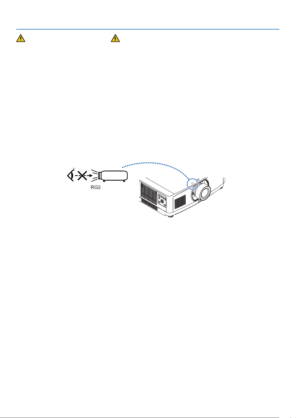
•Donotlookintothelightsourceusingopticalinstruments(suchasmagnifyingglassesandmirrors).Visualimpair-
ment could result.
•Whenturningontheprojector,ensurethatnobodyisfacingtowardsthelensinthepathofthelightemittedfromthe
laser.Donotlookintothelenswhiletheprojectorison.Seriousdamagetoyoureyescouldresult.Thefollowing
label,thatisindicatedatthelens-mounting-sectionontheprojectorcabinet,describesthisprojectoriscategorized
intheriskgroup2ofIEC62471-5:2015.Aswithanybrightlightsource,donotstareintothebeam,RG2IEC62471-
5:2015.
•Performtheadjustmentfrombehindorfromthesideoftheprojector.Adjustingfromthefrontcouldexposeyour
eyestostronglightwhichcouldinjurethem.
•Keepanyitems(magnifyingglassetc.)outofthelightpathoftheprojector.Thelightpathbeingprojectedfromthe
lensisextensive,thereforeanykindofabnormalobjectsthatcanredirectlightcomingoutofthelens,cancause
anunpredictableoutcomesuchasareorinjurytotheeyes.
•Donotplaceanyobjects,whichareeasilyaffectedbyheat,infrontofaprojectorexhaustvent.
Doingsocouldleadtotheobjectmeltingorgettingyourhandsburnedfromtheheatthatisemittedfromtheexhaust
vent.
•Handlethepowercordcarefully.Adamagedorfrayedpowercordcancauseelectricshockorre.
-Donotbendortugthepowercordexcessively.
-Donotplacethepowercordundertheprojector,oranyheavyobject.
-Donotcoverthepowercordwithothersoftmaterialssuchasrugs.
-Donotheatthepowercord.
-Donothandlethepowerplugwithwethands.
•Turnofftheprojector,unplugthepowercordandhavetheprojectorservicedbyaqualiedservicepersonnelunder
thefollowingconditions:
-Whenthepowercordorplugisdamagedorfrayed.
-Ifliquidhasbeenspilledintotheprojector,orifithasbeenexposedtorainorwater.
-Iftheprojectordoesnotoperatenormallywhenyoufollowtheinstructionsdescribedinthisuser’smanual.
-Iftheprojectorhasbeendroppedorthecabinethasbeendamaged.
-Iftheprojectorexhibitsadistinctchangeinperformance,indicatinganeedforservice.
•Disconnectthepowercordandanyothercablesbeforecarryingtheprojector.
•Turnofftheprojectorandunplugthepowercordbeforecleaningthecabinetorcleaningorreplacingthelens.
•Turnofftheprojectorandunplugthepowercordiftheprojectorisnottobeusedforanextendedperiodoftime.
•WhenusingaLANcable:
Forsafety,donotconnecttotheconnectorforperipheraldevicewiringthatmighthaveexcessivevoltage.
•Donotusethemalfunctionedprojector.Itmaycauseofnotonlyelectricshockorrebutalsoseriousdamageto
youreyesight.

v
Important Information
•Donotletchildrentooperatetheprojectorbythemselves.Iftheprojectorisoperatedbychildren,adultsneedto
attendandkeeptheireyesonchildren.
•Ifdamageormalfunctionoftheprojectorisfound,immediatelystoptouseitandconsultyourdealerforrepair.
•Neverdisassemble,repair,andremodelbyendusers.Iftheseareperformedbyendusers,itmaycauseofserious
problem on users’ safety.
•Consultyourdealerfordisposingtheprojector.Neverdisassembletheprojectorbeforedisposingit.
CAUTION
•Donotusethetilt-footforpurposesotherthanoriginallyintended.Misusessuchasgrippingthetilt-footorhang-
ingonthewallcancausedamagetotheprojector.
•Donotholdthecablecoverwhilemovingtheprojectorordonotapplyexcessiveforcetothecablecover.Doing
somaydamagethecablecover,resultingininjury.
•Besuretotightenthescrewsafterattachingthecablecover.Failuretodosomaycausethecablecovertocome
offandfall,resultingininjuryordamagetothecablecover.
•Donotputbundledcablesinthecablecover.Doingsomaydamagethepowercord,resultinginare.
•Select[HIGH]inFanmodeifyoucontinuetousetheprojectorforconsecutivedays.(Fromthemenu,select
[SETUP]→[OPTIONS(1)]→[FANMODE]→[MODE]→[HIGH].)
•Donotunplugthepowercablefromthewalloutletorprojectorwhentheprojectorispoweredon.Doingsocan
causedamagetotheACINterminaloftheprojectorand(or)theprongplugofthepowercable.
ToturnofftheACpowersupplyunderthestatetheprojectorisON,useapowerstripequippedwithaswitch
andabreaker.
•Aminimumoftwopersonsarerequiredtocarrytheprojector.Otherwisetheprojectormaytumbleordrop,caus-
ingpersonalinjury.
Caution on Handling the Optional Lens
Whenshippingtheprojectorwiththelens,removethelensbeforeshippingtheprojector.Alwaysattachthedustcap
tothelenswheneveritisnotmountedontheprojector.Thelensandthelensshiftmechanismmayencounterdam-
agecausedbyimproperhandlingduringtransportation.
Donotholdthelenspartwhencarryingtheprojector.
Doingsocouldcausethefocusringtorotate,resultinginaccidentaldroppingoftheprojector.
Intheconditiontheprojectorisnolensmounted,donotputyourhandsinthelensmountopeningforcarryingthe
projector.
Keephandsawayfromthelensmountingportionwhileperformingalensshift.Failuretodosocouldresultinngers
beingpinchedbythemovinglens.
Remote Control Precautions
•Handletheremotecontrolcarefully.
•Iftheremotecontrolgetswet,wipeitdryimmediately.
•Avoidexcessiveheatandhumidity.
•Donotshort,heat,ortakeapartbatteries.
•Donotthrowbatteriesintore.
•Ifyouwillnotbeusingtheremotecontrolforalongtime,removethebatteries.
•Ensurethatyouhavethebatteries’polarity(+/−)alignedcorrectly.
•Donotusenewandoldbatteriestogether,orusedifferenttypesofbatteriestogether.
•Disposeofusedbatteriesaccordingtoyourlocalregulations.
•Replacetwobatteriesatthesametimewiththequitesameonesthathasbeeninstalledintheremotecontrolor
AAsizedalkalisbatterythatisconformedtoIEC60086-5.
About High Altitude mode
•Set[FANMODE]to[HIGHALTITUDE]whenusingtheprojectorataltitudesapproximately5500feet/1700meters
orhigher.
Usingtheprojectorataltitudesapproximately5500feet/1700metersorhigherwithoutsettingto[HIGHALTITUDE]
cancausetheprojectortooverheatandtheprotectorcouldshutdown.Ifthishappens,waitacoupleminutesand
turn on the projector.

vi
Important Information
•Usingtheprojectorataltitudeslessthanapproximately5500feet/1700metersandsettingto[HIGHALTITUDE]
cancausethelightmoduletoovercool,causingtheimagetoicker.Switch[FANMODE]to[AUTO].
•Usingtheprojectorataltitudesapproximately5500feet/1700metersorhighercanshortenthelifeofopticalcom-
ponentssuchasthelightmodule.
Light Module
1.Alightmodulecontainingmultiplelaserdiodesisequippedintheproductasthelightsource.
2. Theselaserdiodesaresealedinthelightmodule.Nomaintenanceorserviceisrequiredfortheperformanceof
thelightmodule.
3. Enduserisnotallowedtoreplacethelightmodule.
4. Contactqualieddistributorforlightmodulereplacementandfurtherinformation.
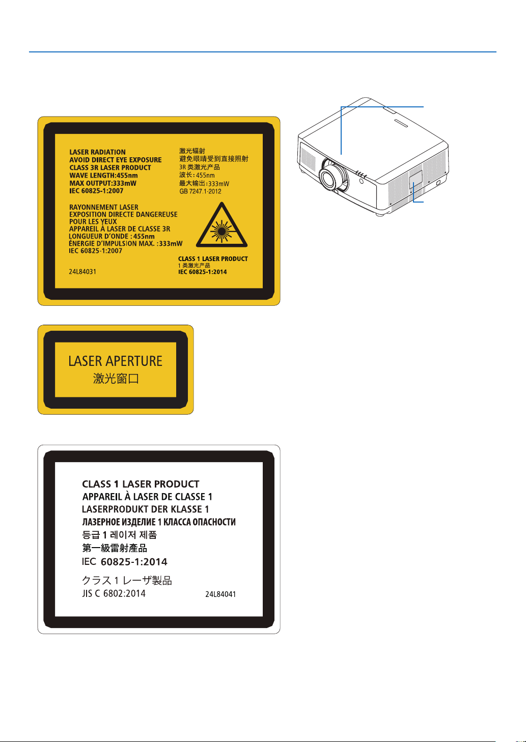
Laser Safety Caution
•For USA
ThisproductisclassiedasClass3RofIEC60825-1Secondedition2007-03
ComplieswithFDAperformancestandardsforlaserproductsexceptfordeviationspursuanttoLaserNoticeNo.
50,datedJune24,2007.
For other regions
ThisproductisclassiedasClass1ofIEC60825-1Thirdedition2014-05andRG2ofIEC62471-5Firstedition
2015-06.
Obeythelawsandregulationsofyourcountryinrelationtotheinstallationandmanagementofthedevice.
•Outlineoflaseremittedfromthebuilt-inlightmodule:
•Wavelength:455nm
•Maximumpower:140W(PA653UL),168W(PA803UL)
•Radiationpatternfromtheprotectivehousing:
•Wavelength:455nm
•Maximumlaserradiationoutput:333mW
•Thelasermoduleisequippedinthisproduct.Useofcontrolsoradjustmentsofproceduresotherthanthosespeci-
edhereinmayresultinhazardousradiationexposure.
CAUTION
•Useofcontrolsoradjustmentsorperformanceofproceduresotherthanthosespeciedhereinmayresultin
hazardousradiationexposure.
CAUTION – CLASS 3R OF IEC 60825-1 SECOND EDITION LASER PRODUCT
LASERLIGHT–AVOIDDIRECTEYEEXPOSURE
vii
Important Information
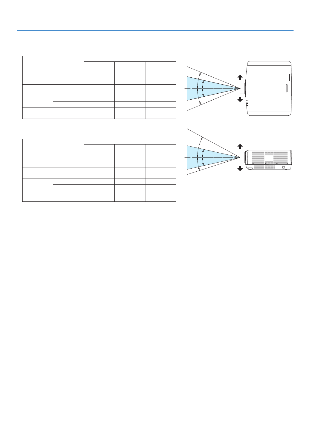
Applicable lens unit: NP40ZL/NP41ZL/NP42ZL
Horizontalangle(unit:degree)
Lens unit Zoom
Lens position
Rightmost
Center
(Reference
value)
Left most
HRHCHL
NP40ZL
Tele31.7 23.8 31.7
Wide41.0 31.9 41.0
NP41ZL
Tele12.8 9.2 12.8
Wide27.7 20.6 27.7
NP42ZL
Tele6.6 4.7 6.6
Wide12.9 9.3 12.9
Verticalangle(unit:degree)
Lens unit Zoom
Lens position
Upper most
Center
(Reference
value)
Lower most
VU VCVD
NP40ZL
Tele29.3 18.3 21.6
Wide38.4 25.0 29.2
NP41ZL
Tele11.7 6.9 8.3
Wide25.6 15.7 18.7
NP42ZL
Tele6.0 3.5 4.2
Wide11.8 7.0 8.4
VC
VC
HC
HC
VU
VD
HR
HL
Lower
Left
Upper
Right
viii
Important Information
•ThecautionandtheexplanatorylabelsoftheLASERPRODUCTinCLASS3RconformingtoIEC60825-1Second
edition,andinClass1conformingtoIEC60825-1Thirdeditionarestuckonthebelowindicatedpositions.
For USA
Label 1
Label 1
Label 2
Label 2
For other regions
Label 1

ix
Important Information
•Manufacturer’sIDLabel(forUSA)
(ForPA803UL)
(ForPA653UL)

x
Important Information
About Copyright of original projected pictures:
Pleasenotethatusingthisprojectorforthepurposeofcommercialgainortheattractionofpublicattentioninavenue
suchasacoffeeshoporhotelandemployingcompressionorexpansionofthescreenimagewiththefollowingfunc-
tionsmayraiseconcernabouttheinfringementofcopyrightswhichareprotectedbycopyrightlaw.
[ASPECTRATIO],[KEYSTONE],Magnifyingfeatureandothersimilarfeatures.
Turkish RoHS information relevant for Turkish market
EEE Yönetmeliğine Uygundur.
Health precautions to users viewing 3D images
Beforeviewing,besuretoreadhealthcareprecautionsthatmaybefoundintheuser’smanualincludedwithyour3D
eyeglassesoryour3DcompatiblecontentsuchasBlu-rayDiscs,videogames,computer’svideolesandthelike.
Toavoidanyadversesymptoms,heedthefollowing:
•Donotuse3Deyeglassesforviewinganymaterialotherthan3Dimages.
•Allowadistanceof2m/7feetorgreaterbetweenthescreenandauser.Viewing3Dimagesfromtooclosea
distance can strain your eyes.
•Avoidviewing3Dimagesforaprolongedperiodoftime.Takeabreakof15minutesorlongeraftereveryhour
ofviewing.
•Ifyouoranymemberofyourfamilyhasahistoryoflight-sensitiveseizures,consultadoctorbeforeviewing3D
images.
•Whileviewing3Dimages,ifyougetsicksuchasnausea,dizziness,queasiness,headache,eyestrain,blurry
vision,convulsions,andnumbness,stopviewingthem.Ifsymptomsstillpersist,consultadoctor.
•View3Dimagesfromthefrontofthescreen.Viewingfromananglemaycausefatigueoreyestrain.
AUTO POWER OFF Function
Thefactorydefaultsettingfor[AUTOPOWEROFF]is15minutes.Ifnoinputsignalisreceivedandnooperationis
performedontheprojectorduring15minutes,theprojectorisautomaticallypoweredoffforsavingthepowercon-
sumption.Inordertocontroltheprojectorbyanexternaldevice,setthe[AUTOPOWEROFF]to[OFF].Pleaserefer
page
131 for details.
xi
Important Information
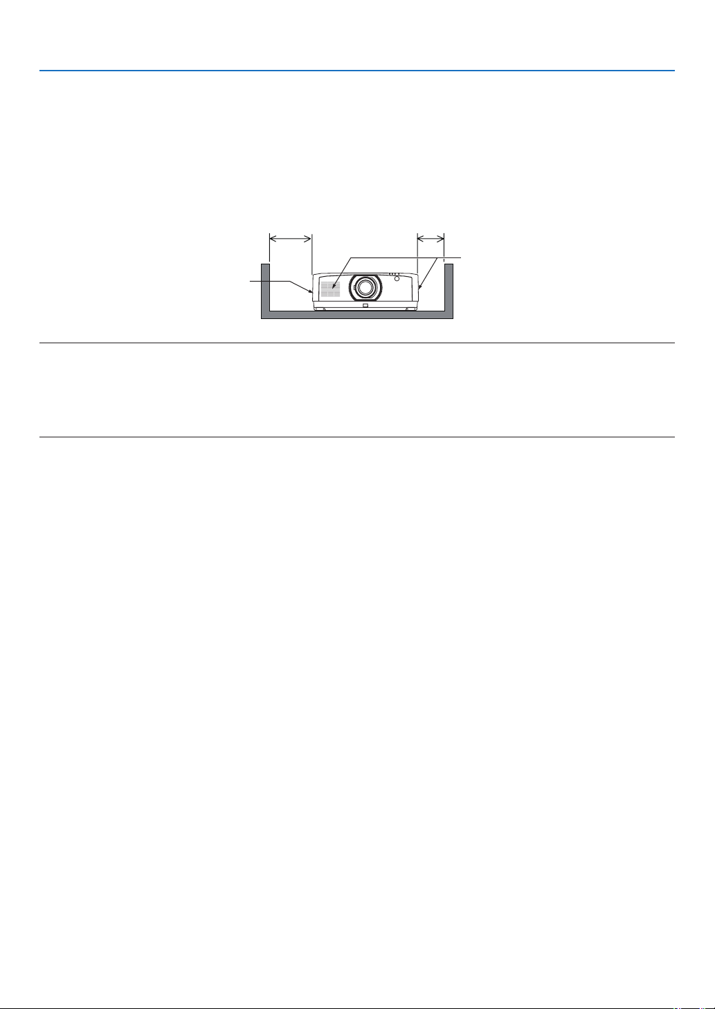
Clearance for Installing the Projector
Allowampleclearancebetweentheprojectoranditssurroundingsasshownbelow.Thehightemperatureexhaust
comingoutofthedevicemaybesuckedintothedeviceagain.Requiredclearanceissamewhenevertheprojector
isinstalledinanyangle.
AvoidinstallingtheprojectorinaplacewhereairmovementfromtheHVACisdirectedattheprojector.
HeatedairfromtheHVACcanbetakeninbytheprojector’sintakevent.Ifthishappens,thetemperatureinsidethe
projectorwillrisetoohighcausingtheover-temperatureprotectortoautomaticallyturnofftheprojectorspower.
20 cm/7.9" or greater 13 cm/5.1" or greater
Intake vent
Exhaust vent
NOTE:
•Thedrawingshowstheproperclearancerequiredfortheleftandrightoftheprojectorassumingsufcientclearancehasbeen
keptforthefront,backandtopoftheprojector.
•Pleaseconsidersufcientclearancetotheprojectorrearsideforsettingthecablecover.
•Fortheportraitprojection,eachrequiredclearancebetweentheoorandtheintakeortheexhaustventissamewiththeclearance
ontheupperillustration.Seepage
148foraninstallationexampleonportraitprojection.

xii
Table of Contents
Important Information ............................................................................................i
1. Introduction ...........................................................................................................1
❶What’sintheBox? ..........................................................................................................1
❷IntroductiontotheProjector ............................................................................................ 2
General .....................................................................................................................2
Lightsource·Brightness ..........................................................................................2
Installation ................................................................................................................. 2
Videos .......................................................................................................................2
Network .....................................................................................................................3
Energy-saving ...........................................................................................................3
About this user’s manual ........................................................................................... 4
❸ Part Names of the Projector ...........................................................................................5
Front/Top ...................................................................................................................5
Rear ..........................................................................................................................6
Mountingthecablecover ..........................................................................................7
Controls/IndicatorPanel ............................................................................................8
Terminals ..................................................................................................................9
❹PartNamesoftheRemoteControl ...............................................................................10
BatteryInstallation .................................................................................................. 11
RemoteControlPrecautions ................................................................................... 11
OperatingRangeforWirelessRemoteControl .......................................................12
2. Projecting an Image (Basic Operation) ...............................................13
❶FlowofProjectinganImage .........................................................................................13
❷ConnectingYourComputer/ConnectingthePowerCord ..............................................14
Usingthepowercordstopper .................................................................................15
❸TurningontheProjector ................................................................................................16
PerformingLensCalibration ...................................................................................16
NoteonStartupscreen(MenuLanguageSelectscreen) ....................................... 17
❹SelectingaSource .......................................................................................................18
❺AdjustingthePictureSizeandPosition ........................................................................20
Adjustingtheverticalpositionofaprojectedimage(Lensshift) .............................21
Focus ......................................................................................................................22
Zoom ....................................................................................................................... 25
AdjustingtheTiltFoot ..............................................................................................26
❻OptimizingComputerSignalAutomatically ...................................................................27
❼TurningUporDownVolume .........................................................................................27
❽TurningofftheProjector ................................................................................................28
❾ After Use .......................................................................................................................29
3. Convenient Features ......................................................................................30
❶Turnoffthelightoftheprojector(LENSSHUTTER) ..................................................... 30
❷TurningofftheImageandSound .................................................................................. 30
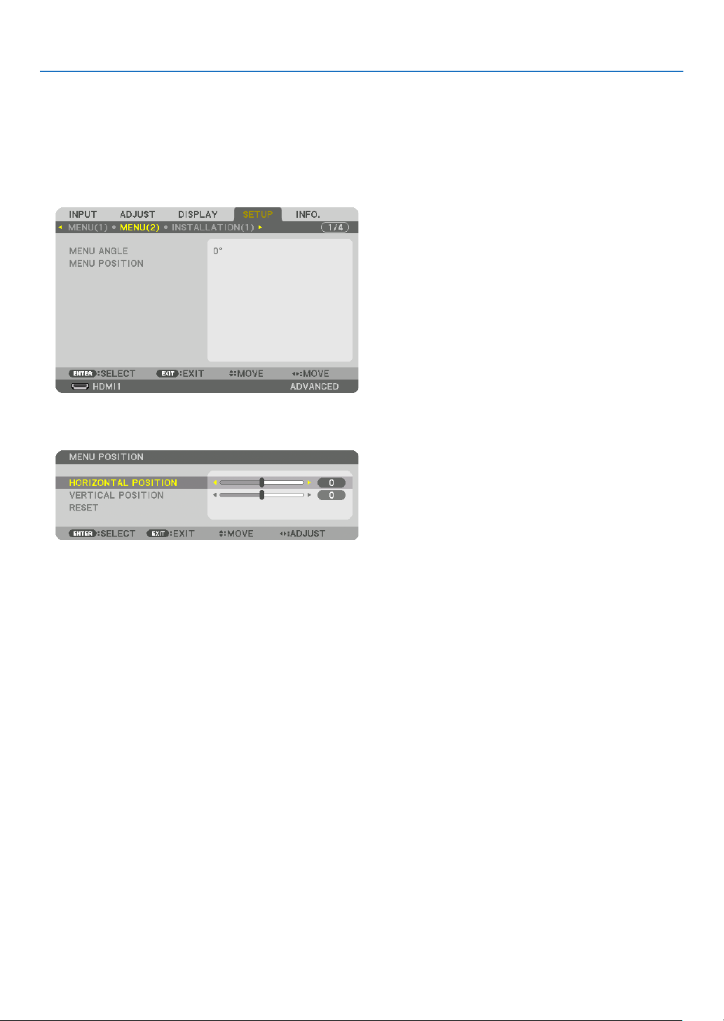
❸ShifttheOn-ScreenMenudisplayingposition ..............................................................31
❹FreezingaPicture ......................................................................................................... 32
❺EnlargingaPicture .......................................................................................................32

xiii
Table of Contents
❻ChangingLIGHTMODE/CheckingEnergy-SavingEffectUsingLIGHTMODE
[LIGHTMODE]........................................................................................................33
CheckingEnergy-SavingEffect[CARBONMETER] ...............................................35
❼CorrectingHorizontalandVerticalKeystoneDistortion[CORNERSTONE] ..................36
❽OperationfortheOn-ScreenMenubyacommerciallyavailableUSBmouse ..............38
Menu operation .......................................................................................................38
Menu position control ..............................................................................................39
Geometriccorrection ...............................................................................................39
❾PreventingtheUnauthorizedUseoftheProjector[SECURITY] ...................................41
❿Projecting3Dvideos .....................................................................................................44
Proceduretowatch3Dvideosusingthisprojector .................................................44
Whenvideoscannotbeviewedin3D .....................................................................46
⓫ControllingtheProjectorbyUsinganHTTPBrowser ...................................................47
⓬StoringChangesforLensShift,Zoom,andFocus[LENSMEMORY]..........................54
Tostoreyouradjustedvaluesin[REF.LENSMEMORY]: .......................................55
Tocallupyouradjustedvaluesfrom[REF.LENSMEMORY]: ................................57
4. Multi-Screen Projection ...............................................................................60
❶Thingsthatcanbedoneusingmulti-screenprojection ................................................60
Case1.Usingasingleprojectortoprojecttwotypesofvideos[PIP/PICTURE
BYPICTURE]..........................................................................................................60
Case2.Usingfourprojectorstoprojectvideoswitharesolutionof3840×
2160pixels[TILING] ...............................................................................................61
Thingstonotewheninstallingprojectors ................................................................63
❷DisplayingTwoPicturesattheSameTime ...................................................................64
Projectingtwoscreens ............................................................................................65
Switchingthemaindisplaywiththesub-displayandviceversa .............................66
Restrictions .............................................................................................................67
❸DisplayingaPictureUsing[EDGEBLENDING] ...........................................................68
Settingtheoverlapofprojectionscreens ................................................................69
[BLENDCURVE].....................................................................................................71
BlackLevelAdjustment ...........................................................................................72
5. Using On-Screen Menu ................................................................................. 74
❶UsingtheMenus ........................................................................................................... 74
❷MenuElements .............................................................................................................75
❸ListofMenuItems ........................................................................................................76
❹MenuDescriptions&Functions[INPUT] ......................................................................82
❺MenuDescriptions&Functions[ADJUST] ...................................................................86
[PICTURE] ..............................................................................................................86
[IMAGEOPTIONS] .................................................................................................90
[VIDEO] ................................................................................................................... 94
[3DSETTINGS] ......................................................................................................96
UsingtheLensMemoryFunction[LENSMEMORY] .............................................. 97
❻MenuDescriptions&Functions[DISPLAY] ..................................................................99
[PIP/PICTUREBYPICTURE] .................................................................................99
[GEOMETRICCORRECTION] ............................................................................. 101
[EDGEBLENDING] ..............................................................................................106
[MULTISCREEN]..................................................................................................107

xiv
Table of Contents
❼MenuDescriptions&Functions[SETUP] ................................................................... 10 9
[MENU(1)] ............................................................................................................. 10 9
[MENU(2)] ............................................................................................................. 110
[INSTALLATION(1)] ................................................................................................111
[INSTALLATION(2)] ............................................................................................... 115
[CONTROL] .......................................................................................................... 116
[NETWORKSETTINGS] .......................................................................................123
[SOURCEOPTIONS] ...........................................................................................128
[POWEROPTIONS] .............................................................................................130
ReturningtoFactoryDefault[RESET] ..................................................................132
❽MenuDescriptions&Functions[INFO.] .....................................................................133
[USAGETIME] ......................................................................................................133
[SOURCE(1)] ........................................................................................................134
[SOURCE(2)] ........................................................................................................134
[SOURCE(3)] ........................................................................................................134
[SOURCE(4)] ........................................................................................................135
[WIREDLAN] ........................................................................................................ 135
[VERSION(1)] .......................................................................................................135
[OTHERS] .............................................................................................................136
[CONDITIONS] .....................................................................................................136
[HDBaseT] ............................................................................................................137
6. Connecting to Other Equipment ...........................................................138
❶Mountingalens(soldseparately) ...............................................................................138
Mountingthelens..................................................................................................138
Removingthelens ................................................................................................140
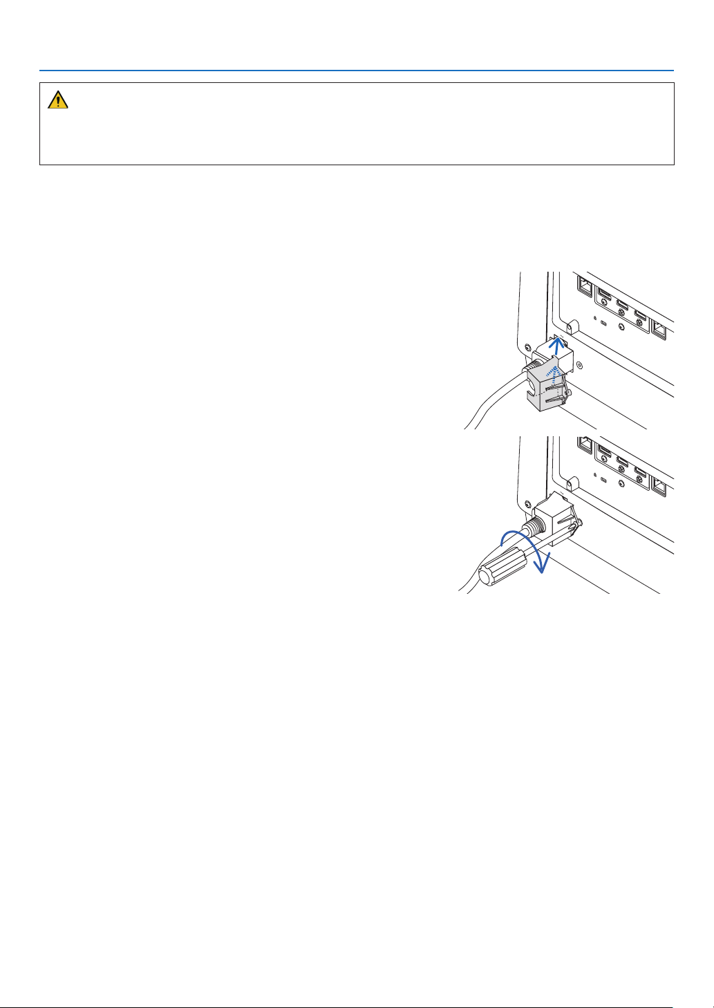
❷MakingConnections ...................................................................................................141
AnalogRGBsignalconnection .............................................................................141
DigitalRGBsignalconnection ..............................................................................142
ConnectingComponentInput ...............................................................................144
ConnectingHDMIInput .........................................................................................145
ConnectingtoaHDBaseTtransmissiondevice(soldcommercially) ....................146
Connectingseveralprojectors .............................................................................. 14 7
Portrait projection (vertical orientation) .................................................................148
ConnectingtoaWiredLAN ................................................................................... 150
7. Maintenance .....................................................................................................151
❶CleaningtheLens.......................................................................................................151
❷CleaningtheCabinet ..................................................................................................151
8. Appendix ..............................................................................................................152
❶Throwdistanceandscreensize .................................................................................152
Lens types and throw distance .............................................................................152
Tablesofscreensizesanddimensions .................................................................153
Lensshiftingrange ................................................................................................153
❷CompatibleInputSignalList ....................................................................................... 15 5
❸Specications .............................................................................................................158
❹CabinetDimensions ...................................................................................................161
❺Pinassignmentsandsignalnamesofmainconnectors .............................................162

xv
Table of Contents
❻ChangingtheBackgroundLogo(VirtualRemoteTool) ...............................................164
❼Troubleshooting ..........................................................................................................165
Featureofeachindicator ......................................................................................165
IndicatorMessage(Statusmessage) ...................................................................165
IndicatorMessage(Errormessage) ......................................................................167
ExplanationonthePOWERindicatorandstandbystate ......................................16 8
CommonProblems&Solutions ............................................................................170
Ifthereisnopicture,orthepictureisnotdisplayedcorrectly. ...............................172
❽PCControlCodesandCableConnection ..................................................................173
ABOUTTHEASCIICONTROLCOMMAND ......................................................... 174
❾TroubleshootingCheckList ......................................................................................... 176
❿REGISTERYOURPROJECTOR!(forresidentsintheUnitedStates,Canada,and
Mexico) .................................................................................................................178
1
1. Introduction
❶ What’s in the Box?
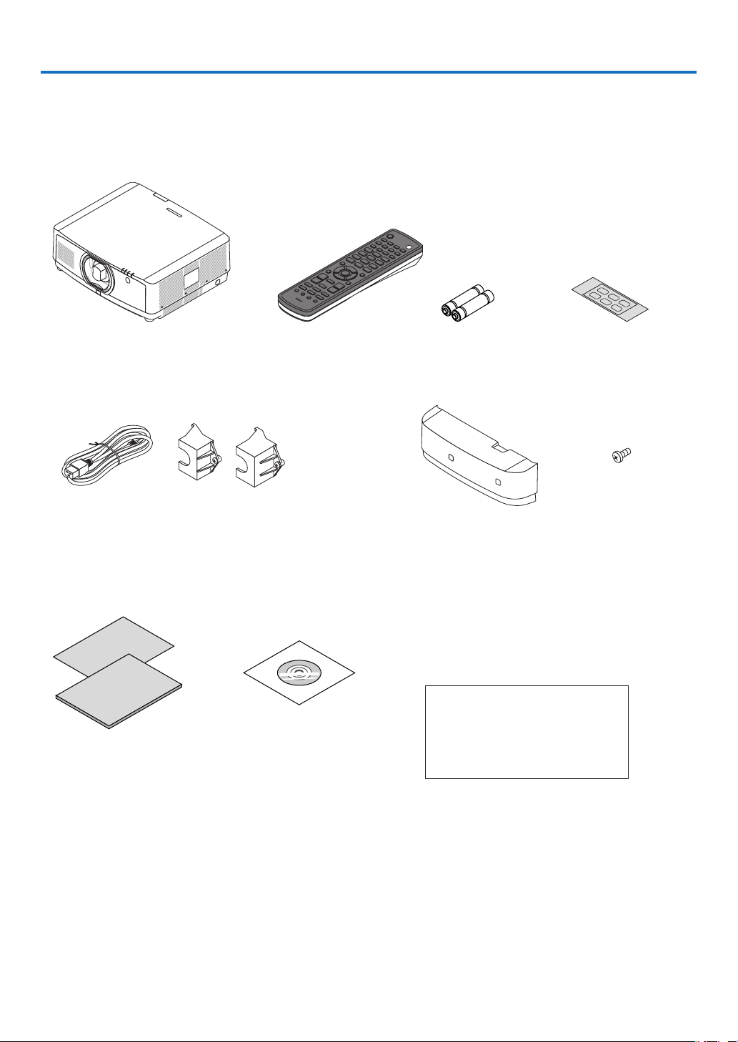
Makesureyourboxcontainseverythinglisted.Ifanypiecesaremissing,contactyourdealer.
Pleasesavetheoriginalboxandpackingmaterialsifyoueverneedtoshipyourprojector.
Projector
Dust cap for lens (24F54091)
* The projector is shipped without
a lens. For the types of lens and
throw distances, see page
152.
Remote control
(7N901081)
AA alkaline batteries
(x2)
Input selection char-
acter sticker
Power cord
(US: 7N080533)
(EU: 7N080030)
Power cord stopper
(24FU2631 for the power cord 7N080533)
(24FU2621 for the power cord 7N080030)
For the preventive measure from dropping
off the power cord.
Cable cover
(24DU4661)
Lens theft prevention
screw (24V00941)
This screw makes it dif-
cult to remove the lens
mounted on the projec-
to r. ( → page 139)
For North America only
Limited warranty
For customers in Europe:
You will nd our current valid Guar-
antee Policy on our Web Site:
www.nec-display-solutions.com
•ImportantInfomation(ForNorth
America: 7N8N7991)
•QuickSetupGuide(ForNorth
America: 7N8N8001) (For Other
countries than North America:
7N8N8001 and 7N8N8011)
•SecuritySticker
(Use this sticker when security
password is set on.)
NEC Projector CD-ROM
User’s manual (PDF)
(7N952581)

2
1. Introduction
❷ Introduction to the Projector
Thissectionintroducesyoutoyournewprojectoranddescribesthefeaturesandcontrols.
General
•Liquidcrystaltypehighbrightness/highresolutionprojector
Model BrightnessResolutionAspectRatio
PA803UL 8000 lm WUXGA(1920×1200)16:10
PA653UL 6500 lm WUXGA(1920×1200)16:10
Light source · Brightness
•Along-lifelaserdiodeisequippedinthelightmodule
Theproductcanbeoperatedatlowcostbecausethelaserlightsourcecanbeusedforalongtimewithoutrequir-
ingreplacementormaintenance.
•Brightnesscanbeadjustedwithinawiderange
Unlikewithordinarylightsources,thebrightnesscanbeadjustedfrom25to100%in1%increments.
•[CONSTANTBRIGHTNESS]mode
Brightnessnormallydecreaseswithuse,butbyselecting[CONSTANTBRIGHTNESS]mode,sensorsinsidethe
projectordetectandautomaticallyadjusttheoutput,therebymaintainingconstantbrightnessthroughoutthelife
ofthelightmodule.
However,ifbrightnessoutputissetatthemaximum,brightnesswilldecreasewithuse.
Installation
•Widerangeofoptionallensesselectableaccordingtotheplaceofinstallation
Thisprojectorsupportsthreetypesofoptionallenses,providingaselectionoflensesadaptedtoavarietyofplaces
of installation and projection methods.
Inaddition,thelensescanbemountedandremovedinonetouch.
Note that no lens is mounted upon shipment from the factory. Please purchase optional lenses separately.
•Motorizedlenscontrolfunctionforeasilyadjustingthepositionoftheprojectedimage
Thepositionoftheprojectedimage(lensshift),Zoom,andFocuscanbeadjustedbybuttonseitheronthecontrol
panel on the side face of the cabinet or the remote control.
•Thisprojectorcanbeinstalleduniversallyineveryangle
Forcontrollingneinclination,usethetiltfoot.Installanappropriatemetalandastandthathasenoughstrength
tosupporttheprojectorforcontrollingtheinstallationangle.
Videos
•Widerangeofinput/outputterminals(HDMI,DisplayPort,HDBaseT,etc.)
Theprojectorisequippedwithavarietyofinput/outputterminals:HDMI(input×2),DisplayPort,HDBaseT(input
x1,outputx1),computer(analog),etc.
Theprojector’sHDMIinput,DisplayPortinputterminalsandHDBaseTPortssupportHDCP.
•HDMIandHDBaseTsupportHDCP2.2/1.4
•DisplayPortsupportsHDCP1.4
•Simultaneousdisplayof2images(PIP/PICTUREBYPICTURE)
Twoimagescanbeprojectedsimultaneouslywithasingleprojector.
Therearetwotypesoflayoutsforthetwoimages:“picture-in-picture”inwhichasub-pictureisdisplayedonthe
mainpicture,and“picture-by-picture”inwhichthemainandsubpicturesaredisplayednexttoeachother.

3
1. Introduction
•Multi-screenprojectionusingmultipleprojectors
ThisprojetorequipstheHDBaseTIN/EthernetandHDBaseTOUT/Ethernetports.Multipleprojectorsinsame
brightnessuptofourunitscanbeconnetedinadaisychainbyaLAN*
1
cableviatheseterminals.Ahighquality
pictureisachievedbydividingandprojectinghighresolutionvideosamongthevariousprojectors.
Furthermore,theboundariesofthescreensaresmoothedusinganedgeblendingfunction.
*
1
UseacommerciallyavailableCAT5eSTPcableoroneinahigherspecication.
•Seamlessswitchfunctionforsmootherscreenchangeswhenswitchingthesignal
Whentheinputconnectorisswitched,theimagedisplayedbeforeswitchingisheldsothatthatthenewimagecan
beswitchedtowithoutabreakduetoabsenceofasignal.
•SupportsHDMI3Dformat
Thisprojectorcanbeusedtowatchvideosin3Dusingcommercially-availableactiveshutter-type3Deyewearand
3DemittersthatsupportXpand3D.
Network
•SupportswiredLAN
EquipstheLANandHDBaseT/Ethernet(RJ-45)ports.UtilizingawiredLANconnectedwiththeseports,itenables
to control the projector by a computer.
•CRESTRONROOMVIEWandExtronXTPcompatibility
TheprojectorsupportsCRESTRONROOMVIEWandExtronXTP,allowingmultipledevicesconnectedinthe
networktobemanagedandcontrolledfromacomputer.Moreover,itenablestooutputandcontrolimageviaan
ExtronXTPtransmitterconnectedwiththeprojector.
•Convenientutilitysoftware(UserSupportware)providedasstandard
Thisprojectorsupportsourutilitysoftware(NaViSetAdministrator2,VirtualRemoteTool,etc.).
NaViSetAdministrator2helpsyoucontroltheprojectorbyacomputerviawiredLANconnection.
VirtualRemoteToolhelpsyouperformoperationsbyavirtualremotecontrolsuchasprojector’spoweronoroff
andsignalselectionviawiredLANconnection.Moreover,ithasfunctiontosendanimagetotheprojectorand
registeritasthelogodata.
Pleasevisitourwebsitefordownloadingeachsoftware.
URL:http://www.nec-display.com/dl/en/index.html
Energy-saving
•Energy-savingdesignwithastandbypowerconsumptionof0.15W(100-130VAC)/0.21W(200-240VAC)
Whentheon-screenmenu’sstandbymodeissetto“NORMAL”,thepowerconsumptioninthestandbymodeac-
tivatingthePowerManagementis0.15W(100-130VAC)/0.21W(200-240VAC)and0.11W(100-130VAC)/
0.16W(200-240VAC)whenLANisineffective.
•[LIGHTMODE]forlowpowerconsumptionand“CarbonMeter”display
Theprojectorisequippedwithan[LIGHTMODE]forreducingpowerconsumptionduringuse.Furthermore,the
power-savingeffectwhenoneoptionamong[ECO1],[ECO2]and[LONGLIFE]issetisconvertedintotheamount
ofreductionsofCO
2
emissionsandthisisindicatedontheconrmationmessagedisplayedwhenthepoweris
turnedoffandat[INFORMATION]ontheon-screenmenu(CARBONMETER).

4
1. Introduction
About this user’s manual
Thefastestwaytogetstartedistotakeyourtimeanddoeverythingrightthersttime.Takeafewminutesnowto
reviewtheuser’smanual.Thismaysaveyoutimelateron.Atthebeginningofeachsectionofthemanualyou’llnd
anoverview.Ifthesectiondoesn’tapply,youcanskipit.
5
1. Introduction
❸ Part Names of the Projector
Front/Top
Thelensissoldseparately.ThedescriptionbelowisforwhentheNP41ZLlensismounted.
Controls
(→ page
8)
Lens
Remote Sensor (located on the
front and the rear)
(→ page
12)
Remote Sensor
(→ page
12)
Lens Cap
(The optional lens is shipped with
the lens cap.)
Adjustable Tilt Foot
(→ page 26)
Indicator Section
(→ page
8)
Lens Release Button
(→ page
140)
Adjustable Tilt Foot
(→ page 26)
Exhaust vent
Heated air is exhausted from here.
Howtopastetheinputselectioncharacterstickeroftheremotecontrol
•PeeloffthecoverofthestickerandalignthestickerholeswithButtons1to6beforepasting.
•Pleasetakecarenottoletthestickercontactthebuttonswhenpasting.
•Theexplanationsandillustrationsinthismanualareprovidedwiththestickerpasted.
Intake vent
(→ page xi, 148)
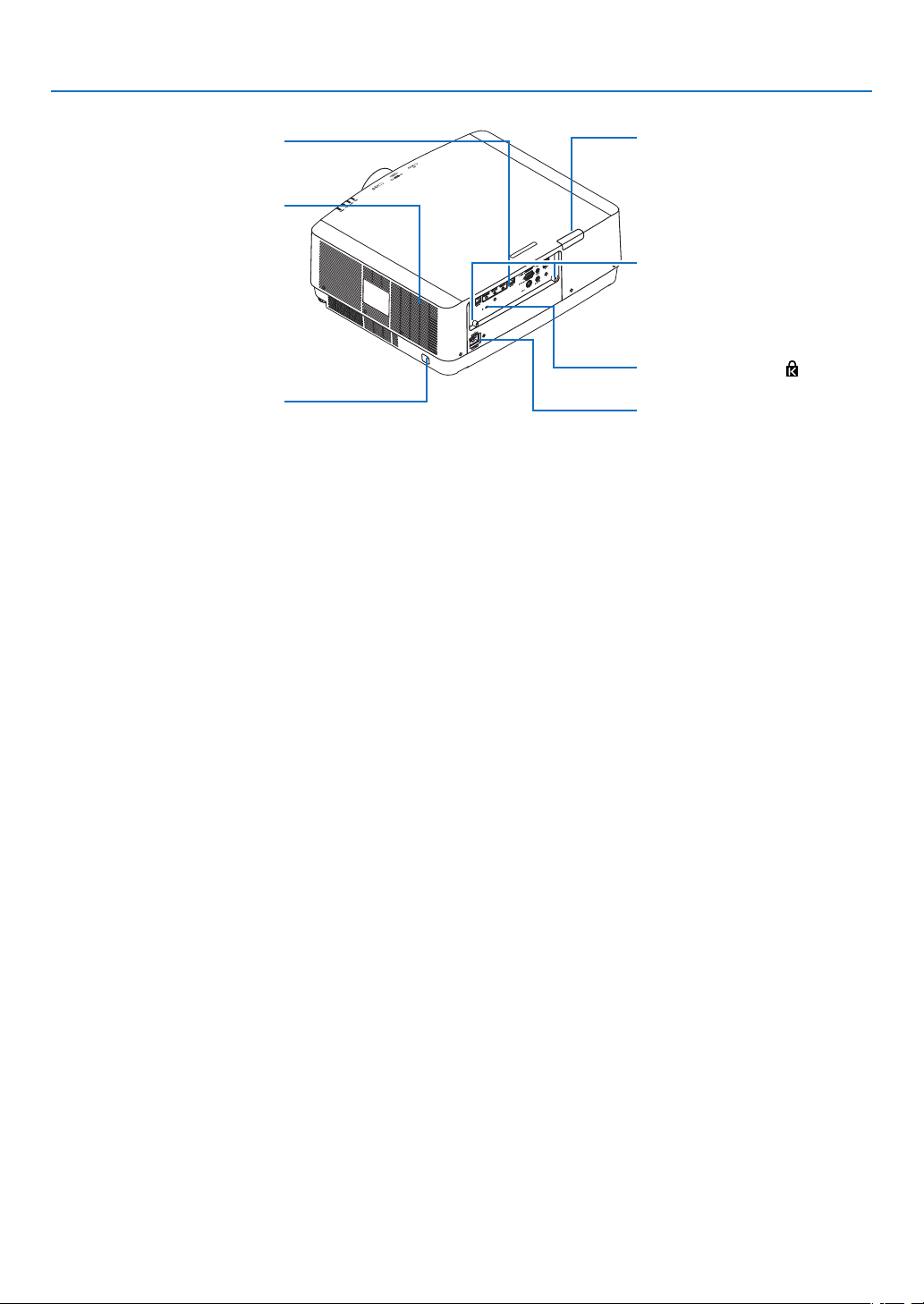
6
1. Introduction
Terminals
(→ page 9)
Rear
Remote Sensor (located on the
front and the rear)
(→ page
12)
AC IN Terminal
Connect the supplied power cord’s
three-pin plug here, and plug the
other end into an active wall outlet.
(→ page
14)
*ThissecurityslotsupportstheMicroSaver
®
SecuritySystem.
Built-in Security Slot (
)*
Cable cover connection
(right and left)
Screw holes and grooves for the
optional cable cover
(→ page
7)
Intake vent
(→ page
xi, 148)
Security Bar
Attach an anti-theft device.
The security bar accepts security
wires or chains up to 0.18 inch/4.6
mm in diameter.
7
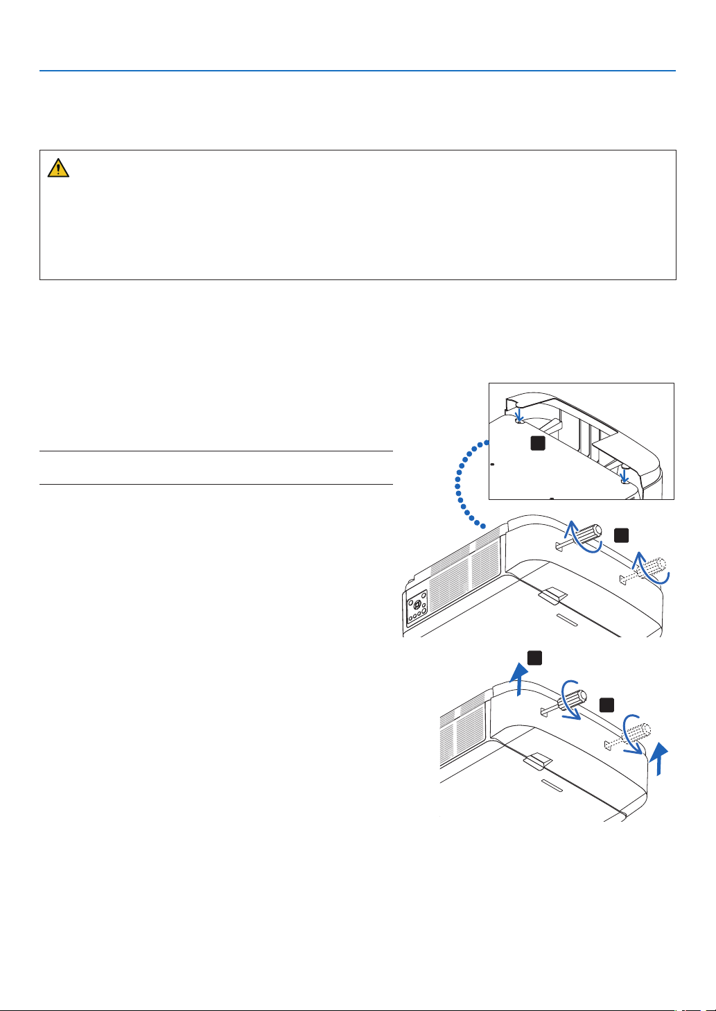
1. Introduction
Mounting the cable cover
Mountingthecablecoverontheprojectorallowsyouhidethecablesforatidyappearance.
CAUTION
•Aftermountingthecablecover,besuretofastenusingthescrewsprovided.Ifnot,thecablecovercouldfall
anddamagethecablecoverandpossiblyresultingininjury.
•Donotbundlethepowercordandplaceitunderthecablecover.Doingsocouldleadtore.
•Donotholdthecablecoverwhilemovingtheprojectoranddonotapplyexcessiveforcetothecablecover.
Doingsocoulddamagethecablecover,resultingintheprojectorfallingorcausinginjury.
Mounting
Preparations:
1. Connect the power cord and cables to the projector (the connection cords are omitted from the diagrams).
2. Prepare a Phillips screwdriver.
1.Insertthetworoundprotrusionsontheleftandrightedges
ofthecablecoverintothegroovesinthebottomofthe
projectortolineitup.
NOTE:Becarefulnottoletthepowercordandcablesgetpinchedbythe
cablecover.
2.Turnthecablecoverscrewclockwise.
•Tightenthescrewsecurely.
2
1
Removing
1.Turnthecablecoverscrewcounterclockwiseuntilitturns
loosely.
•Holdthecablecoverwhiledoingthistopreventitfrom
falling.
•Thescrewdoesnotcomecompletelyoff.
2.Removethecablecover.
•Turnthecablecoveralittle,thenliftitoff.
1
2
8
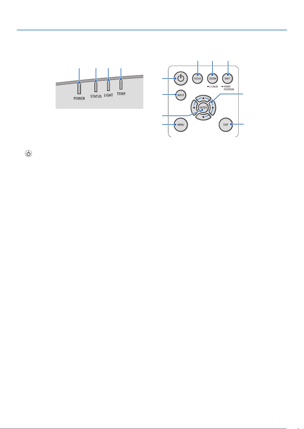
1. Introduction
Controls/Indicator Panel
2 3 4 5
10
7
8
1
6
9
11 12 13
1. (POWER)Button
(→page16,28)
2. POWER Indicator
(→page
14,16,28,165,166,167)
3. STATUS Indicator
(→page
165,166,167)
4.LIGHTIndicator
(→page
165,166,167)
5.TEMP.Indicator
(→page
165,166,167)
6.INPUTButton
(→page
18)
7.MENUButton
(→page
74)
8. ▲▼◀▶/VolumeButtons◀▶
(→page
27,74)
9.ENTERButton
(→page
74)
10.EXITButton
(→page
74)
11.FOCUSButton
(→page
23)
12.ZOOM/L-CALIB.Button
(→page
25)
13.SHIFT/HOMEPOSITIONButton
(→page
21)
9
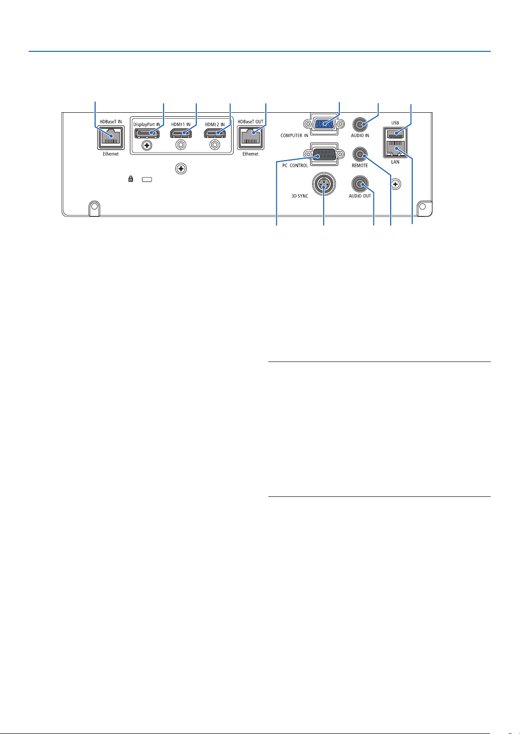
1. Introduction
Terminals
2 73 1
4
5
811
12
13 10
6 9
1.HDMI1INTerminal(TypeA)
(→page142,143,145)
2.HDMI2INTerminal(TypeA)
(→page
142,143,145)
3. DisplayPort IN Terminal
(→page
142)
4.COMPUTERIN/ComponentInputTerminal(Mini
D-Sub15Pin)
(→page
141,144)
5.COMPUTERAUDIOINMiniJack(StereoMini)
(→page
141,143)
6.HDBaseTIN/EthernetPort(RJ-45)
(→page
146,147)
7. HDBaseTOUT/EthernetPort(RJ-45)
(→page
61,147)
8.AUDIOOUTMiniJack(StereoMini)
(→page
141,143,145)
9.USB-APort(TypeA)
(→page
38)
10. LANPort(RJ-45)
(→page
150)
11.3DSYNCTerminal(MiniDIN3Pin)
(→page
44)
12.PCCONTROLPort(D-Sub9Pin)
(→page
163)
UsethisporttoconnectaPCorcontrolsystem.
Thisenablesyoutocontroltheprojectorusingserial
communicationprotocol.Ifyouarewritingyourown
program,typicalPCcontrolcodesareonpage
173.
13.REMOTETerminal(StereoMini)
Use this terminal for wired remote control of the pro-
jectorusingtheNECremotecontrol,RD-465E.
Connecttheprojectorandourremotecontrol,RD-
465E,usingacommerciallyavailablewiredremote
control cable.
NOTE:
•WhenaremotecontrolcableisconnectedtotheREMOTE
terminal,infraredremotecontroloperationscannotbeper-
formed.
•When[HDBaseT]isselectedinthe[REMOTESENSOR]
andtheprojectorisconnectedtoacommercially-available
transmissiondevicethatsupportsHDBaseT,remotecontrol
operationsininfra-redcannotbecarriedoutiftransmission
ofremotecontrolsignalshasbeensetupinthetransmission
device.However,remotecontrolusinginfraredrayscanbe
carriedoutwhenthepowersupplyofthetransmissiondevice
isswitchedoff.
10
1. Introduction
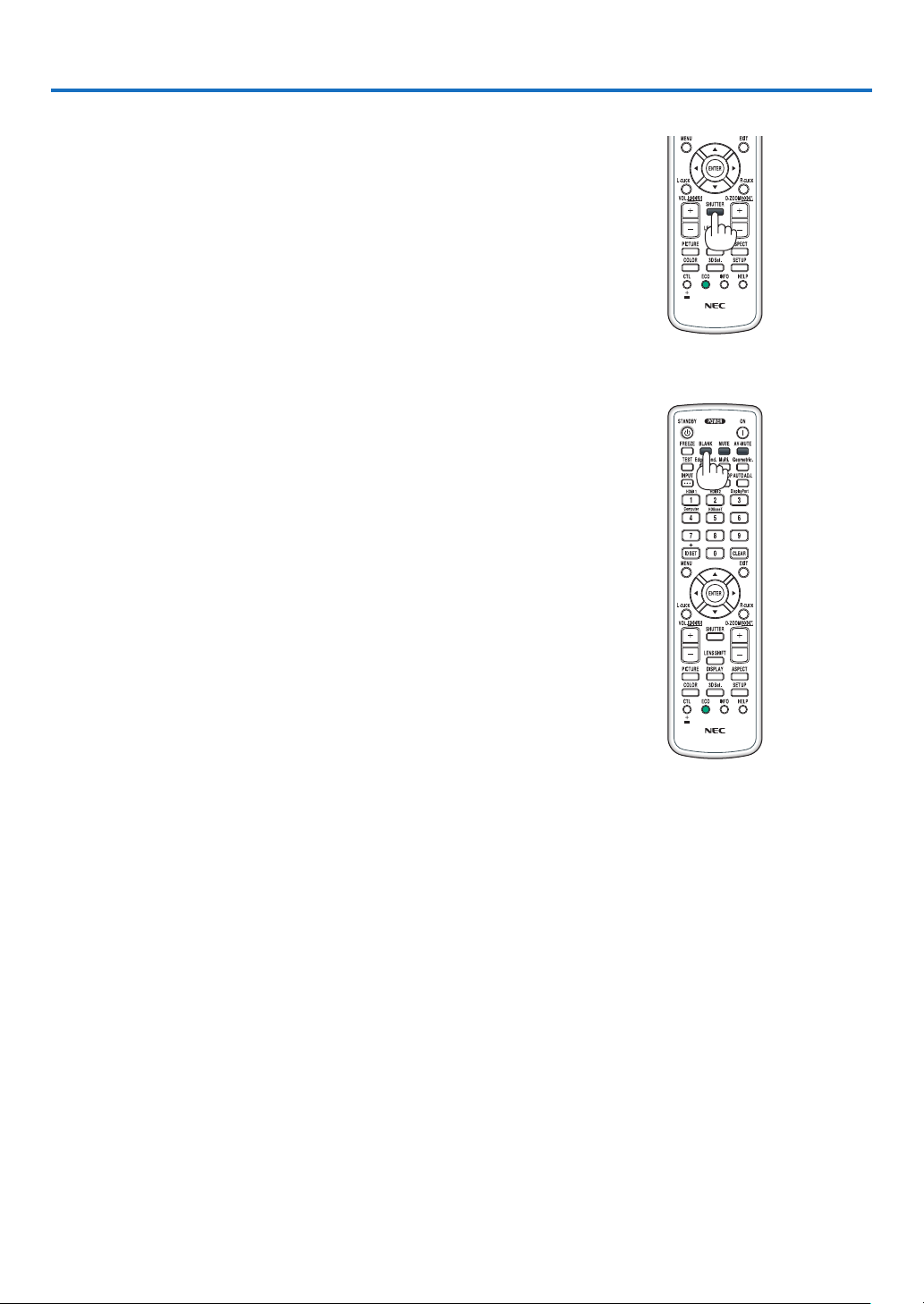
❹ Part Names of the Remote Control
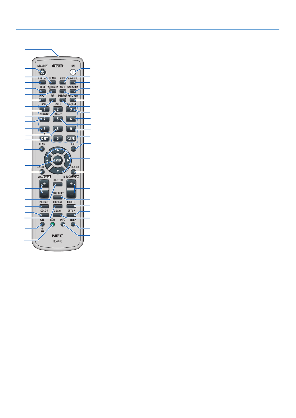
9.EdgeBlend.Button
(→page
69)
10.Multi.Button
(→page
107)
11.Geometric.Button
(→page
36,101)
12.INPUTButton
(→page
18)
13.PIPButton
(→page
64)
14.PBP/POPButton
(→page
64)
15.AUTOADJ.Button
(→page
27)
16.1(HDMI1)Button
(→page
18)
17.2(HDMI2)Button
(→page
18)
18.3(DisplayPort)Button
(→page
18)
19.4(Computer)Button
(→page
18)
20.5(HDBaseT)Button
(→page
18)
21.6Button
(not available on this series of
projectors)
22.7Button
(not available on this series of
projectors)
23.8Button
(not available on this series of
projectors)
24.9Button
(not available on this series of
projectors)
25.IDSETButton
(→page
121)
26.NumericKeypadButton/
CLEARButton
(→page
121)
27.MENUButton
(→page
74)
28.EXITButton
(→page
74)
1.InfraredTransmitter
(→page
12)
2.POWERONButton
(→page
16)
3.STANDBYButton
(→page
28)
4.FREEZEButton
(→page
32)
5.BLANKButton
(→page
30)
6.MUTEButton
(→page
30)
7.AV-MUTEButton
(→page
30)
8.TESTButton
(→page85)
29. ▲▼◀▶Button
(→page
74)
30.ENTERButton
(→page
74)
31.L-CLICKButton*
32.R-CLICKButton*
33.VOL./FOCUS(+)(−)Button
(→page
23,27)
34.D-ZOOM/ZOOM(+)(−)Button
(→page
25,32)
35.SHUTTERButton
(→page
30)
36.LENSSHIFTButton
(→page
21)
37.PICTUREButton
(→page
86)
38.DISPLAYButton
(→page
99)
39.ASPECTButton
(→page
92)
40.COLORButton
(→page
88)
41.3DSet.Button
(→page
44)
42.SETUPButton
(→page
109)
43.CTLButton
(→page
23,24,25)
44.ECOButton
(→page
33)
45.INFOButton
(→page
134)
46.HELPButton
(→page
133)
1
3
5
4
8
9
12
13
2
6
7
11
10
15
14
16
19
22
25
23
17
27
31
33
35
30
21
28
29
20
32
24
26
18
34
36
43
44
46
45
37
40
38
42
41
39
*The▲▼◀▶,L-CLICKandR-CLICKbuttonsworkonlywhenaUSBcableisconnectedwithyourcomputer.
11
1. Introduction
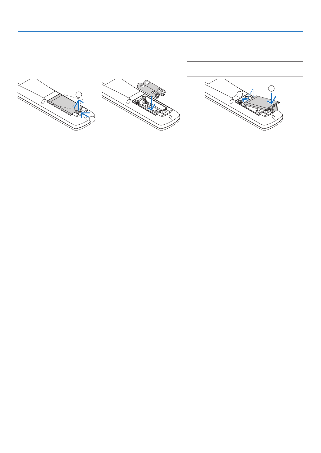
Battery Installation
1.Pressthecatchandremove
thebatterycover.
2.Installnewones(AA).En-
surethatyouhavethebat-
teries’polarity(+/−)aligned
correctly.
3.Slipthecoverbackoverthebatteriesuntil
itsnapsintoplace.
NOTE:Donotmixdifferenttypesofbatteriesornew
andoldbatteries.
1
2
1
2
Remote Control Precautions
•Handletheremotecontrolcarefully.
•Iftheremotecontrolgetswet,wipeitdryimmediately.
•Avoidexcessiveheatandhumidity.
•Donotshort,heat,ortakeapartbatteries.
•Donotthrowbatteriesintore.
•Ifyouwillnotbeusingtheremotecontrolforalongtime,removethebatteries.
•Ensurethatyouhavethebatteries’polarity(+/−)alignedcorrectly.
•Donotusenewandoldbatteriestogether,orusedifferenttypesofbatteriestogether.
•Disposeofusedbatteriesaccordingtoyourlocalregulations.
•Replacetwobatteriesatthesametimewiththequitesameonesthathasbeeninstalledintheremotecontrolor
AAsizedalkalisbatterythatisconformedtoIEC60086-5.
12
1. Introduction
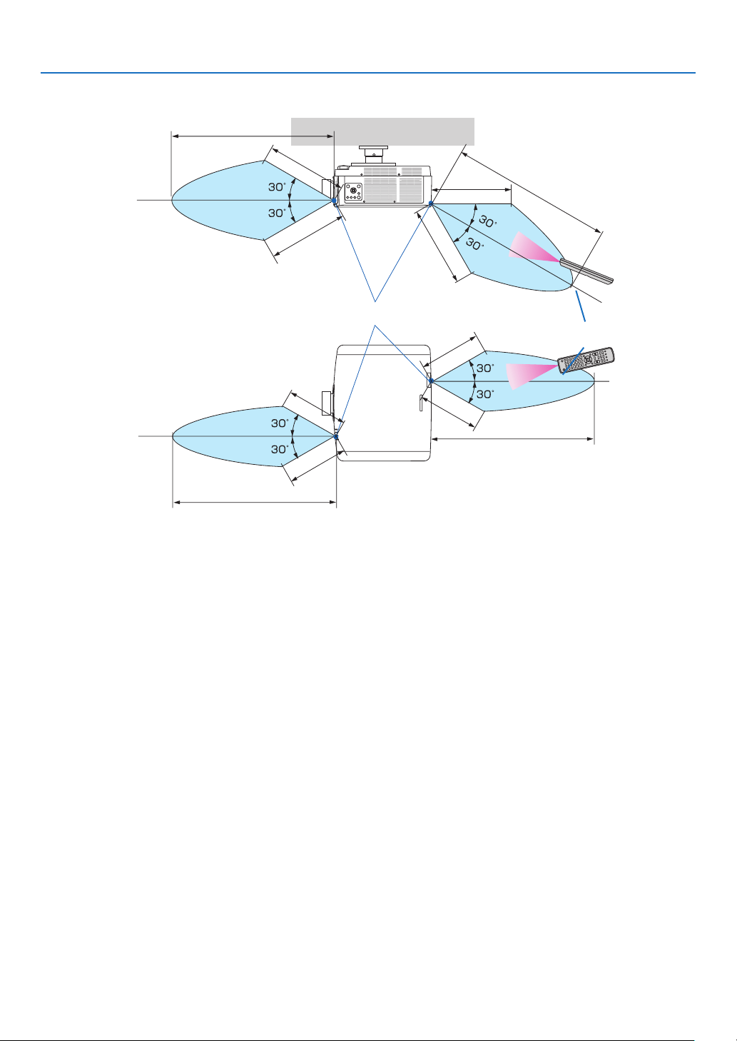
Operating Range for Wireless Remote Control
40 m/1575 inch
40 m/1575 inch
Remote control
Remote sensor on projector cabinet
40 m/1575 inch
40 m/1575 inch
20 m/787 inch
20 m/787 inch
20 m/787 inch
20 m/787 inch
15 m/591 inch
15 m/591 inch
15 m/591 inch
15 m/591 inch
•Theinfraredsignaloperatesbyline-of-sightuptoadistanceofabovemetersandwithina60-degreeangleofthe
remote sensor on the projector cabinet.
•Theprojectorwillnotrespondifthereareobjectsbetweentheremotecontrolandthesensor,orifstronglightfalls
onthesensor.Weakbatterieswillalsopreventtheremotecontrolfromproperlyoperatingtheprojector.

13
Thissectiondescribeshowtoturnontheprojectorandtoprojectapictureontothescreen.
❶ Flow of Projecting an Image
Step1
•Connectingyourcomputer/Connectingthepowercord(→page
14)
Step2
•Turningontheprojector(→page
16)
Step3
•Selectingasource(→page
18)
Step4
•Adjustingthepicturesizeandposition(→page
20)
•Correctingkeystonedistortion[CORNERSTONE](→page
36, 101)
Step5
•Adjustingapictureandsound
- Optimizing a computer signal automatically (→ page
27)
- Turning up or down volume (→ page
27)
Step6
•Makingapresentation
Step7
•Turningofftheprojector(→page
28)
Step8
•Afteruse(→page
29)
2. Projecting an Image (Basic Operation)
14
2. Projecting an Image (Basic Operation)
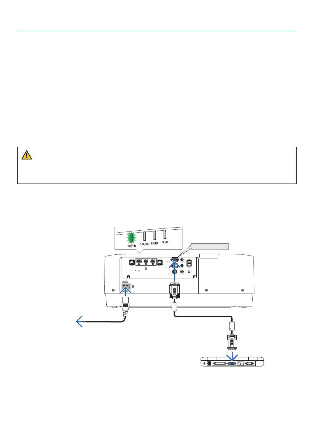
❷ Connecting Your Computer/Connecting the Power Cord
1.Connectyourcomputertotheprojector.
This section will show you a basic connection to a computer. For information about other connections, see “6-2
Making Connections” on page
141.
Connect the display output terminal (mini D-sub 15 pin) on the computer to the computer video input terminal
on the projector with a commercially-available computer cable (with ferrite core) and then turn the knobs of the
connectors to secure them.
2.Connectthesuppliedpowercordtotheprojector.
First connect the supplied power cord’s three-pin plug to the AC IN terminal of the projector, and then connect
another plug of the supplied power cord directly in the wall outlet. Do not use any plug converter.
CAUTION
•Topreventthepowercordfromcomingloose,makesurethatalltheprongsofthepowercordplugarefullyin-
sertedintotheACINterminaloftheprojectorbeforeusingthepowercordstopper.Aloosecontactofthepower
cordmaycauseareorelectricshock.
Upon connecting the power cable, the POWER indicator of the projector will light in green. If there are no input
signals, the device will go into the standby state.
(In the state, standby mode is NORMAL.) (→page
130)
COMPUTER IN
Make sure that the prongs are fully inserted into
both the AC IN and the wall outlet.
To wall outlet
Computer cable (with ferrite core)
(sold commercially)
15
2. Projecting an Image (Basic Operation)
CAUTION:
PartsoftheprojectormaybecometemporarilyheatediftheprojectoristurnedoffwiththePOWERbuttonorifthe
ACpowersupplyisdisconnectedduringnormalprojectoroperation.
Usecautionwhenpickinguptheprojector.
Using the power cord stopper
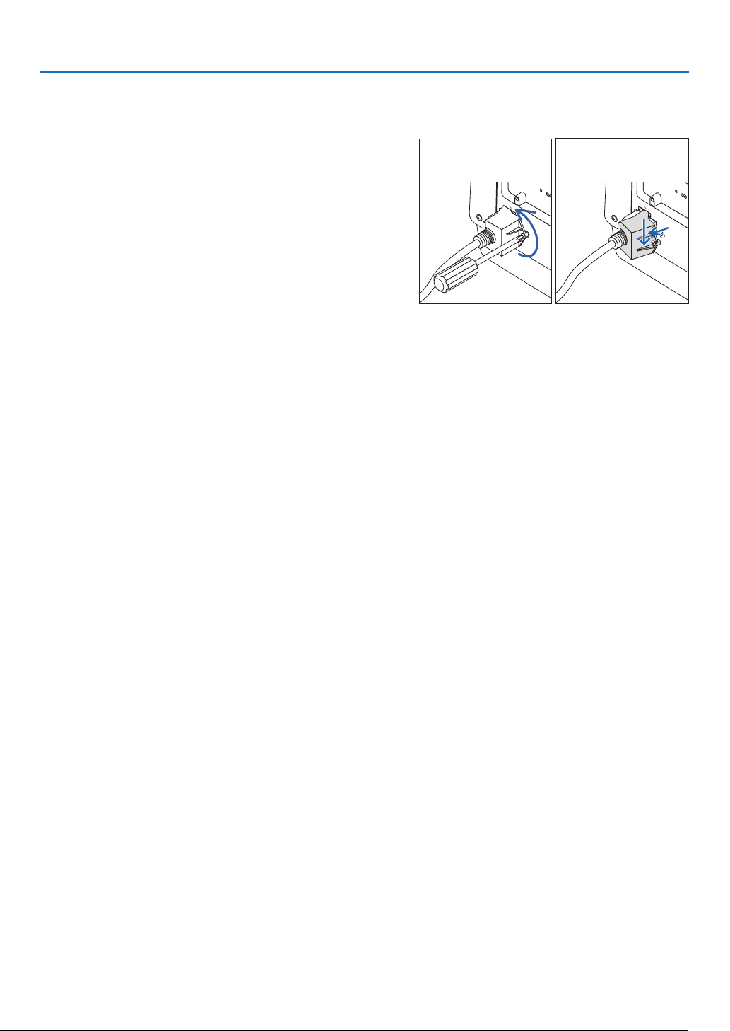
TopreventthepowercordfromaccidentlyremovingfromtheACINoftheprojector,usethepowercordstopper.
Requiredtool:Phillipsscrewdriver
1.Mountthepowercordstopperoverthepowerplugthatconnected
totheACINterminal.
2.Fastenthescrewonthepowercordstopper.
16
2. Projecting an Image (Basic Operation)
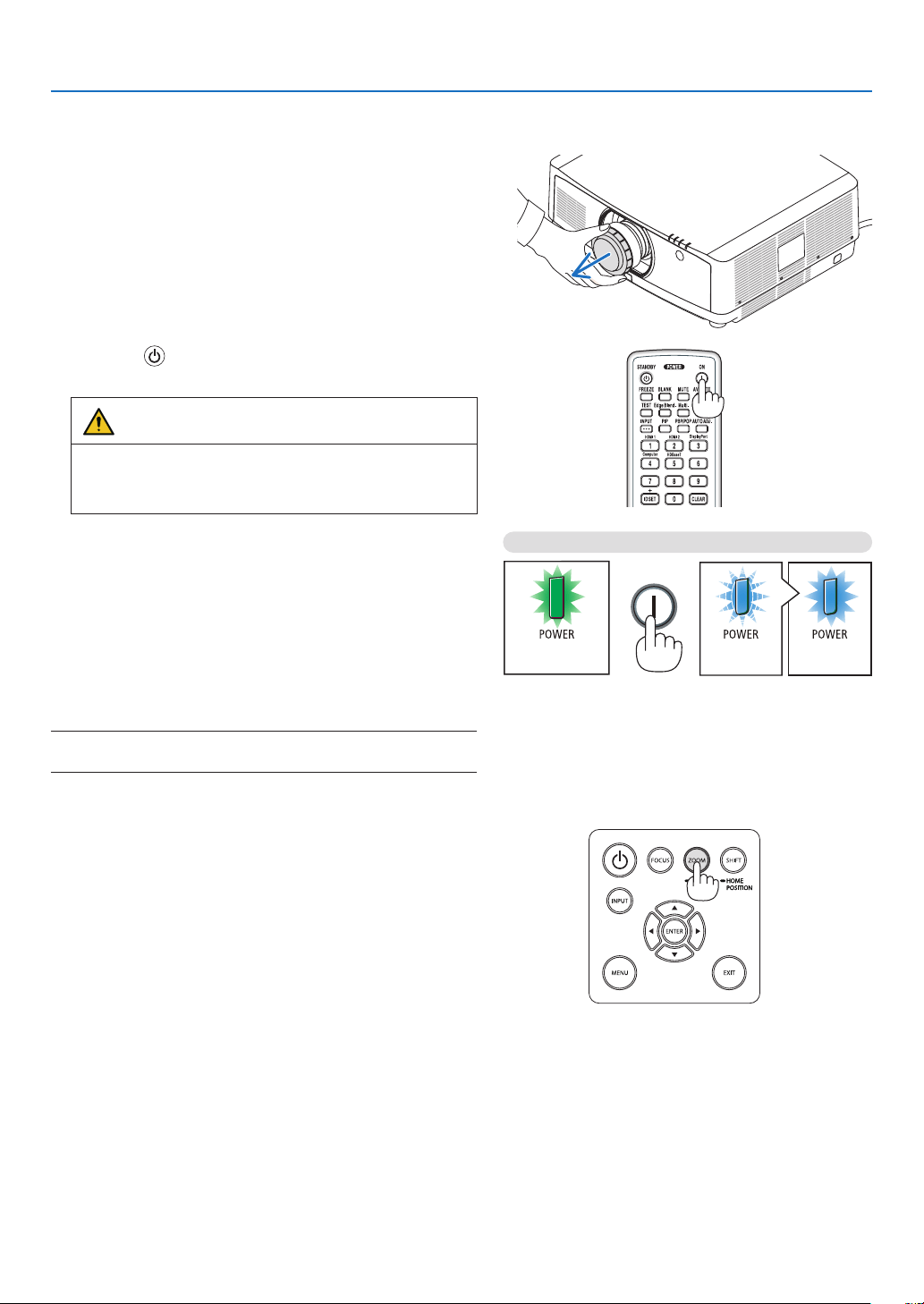
❸ Turning on the Projector
1.Removethelenscap.
2.Pressthe(POWER)buttonontheprojectorcabinet
orthePOWERONbuttonontheremotecontrol.
WARNING
Theprojectorproducesastronglight.Whenturningon
thepower,makesurenoonewithinprojectionrangeis
lookingatthelens.
The POWER indicator lit in green will start to blink in blue.
After that, the image will be projected onto the screen.
TIP:
•Whenthemessage“PROJECTORISLOCKED!ENTERYOUR
PASSWORD.”isdisplayed,itmeansthatthe[SECURITY]
featureisturnedon.(→page
41)
After you turn on your projector, ensure that the computer
or video source is turned on.
NOTE:Abluescreen(bluebackground)isdisplayedwhennosignal
isbeinginput(byfactorydefaultmenusettings).
Sleep state Blinking Power On
Blinking in green
Blinking blue
light
Steady blue
light
(→page
165)
Performing Lens Calibration
Aftermountingtheseparatelyavailablelensunitorreplacing
alensunit,perform[LENSCALIBRATION]byholdingtopress
ZOOM/L-CALIB.buttononthecabinetovertwoseconds.
Calibrationcorrectstheadjustablezoom,shift,andfocus
range.Ifcalibrationisnotperformed,youmaynotbeableto
getthebestfocusandzoomevenifyouadjustthefocusand
zoomforthelens.
17
2. Projecting an Image (Basic Operation)
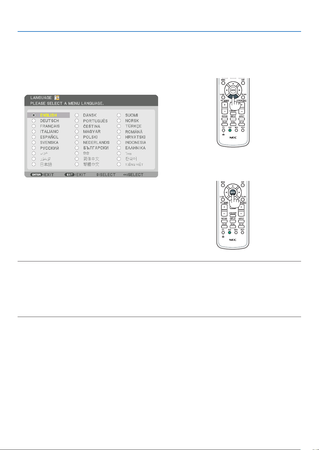
Note on Startup screen (Menu Language Select screen)
Whenyourstturnontheprojector,youwillgettheStartupmenu.Thismenugivesyoutheopportunitytoselectone
ofthe30menulanguages.
Toselectamenulanguage,followthesesteps:
1.Usethe▲, ▼, ◀ or ▶buttontoselectoneofthe30
languagesfromthemenu.
2.PresstheENTERbuttontoexecutetheselection.
Afterthishasbeendone,youcanproceedtothemenu
operation.
Ifyouwant,youcanselectthemenulanguagelater.
(→[LANGUAGE]onpage
78 and 109)
NOTE:
•Ifthemessage,[PLEASESET"DATEANDTIME".]isshown,pleasesetthecurrentdateandtime.(→page120)
•Inthecasethismessageisnotshown,the[DATEANDTIMESETTING]isrecommendedtocomplete.
•Keepthelenscapoffthelenswhiletheprojector’spowerison.
Ifthelenscapison,itcouldbewarpedduetohightemperature.
•IftheSTATUSindicatorlightsorangewiththepowerbuttonpressed,theprojectorwillnotbeturnedonsincethe[CONTROL
PANELLOCK]hasbeenON.Cancelthelockbyturningitoff.(→page120)
•WhilethePOWERindicatorisblinkingblueinshortcycles,thepowercannotbeturnedoffbyusingthepowerbutton.
18
2. Projecting an Image (Basic Operation)
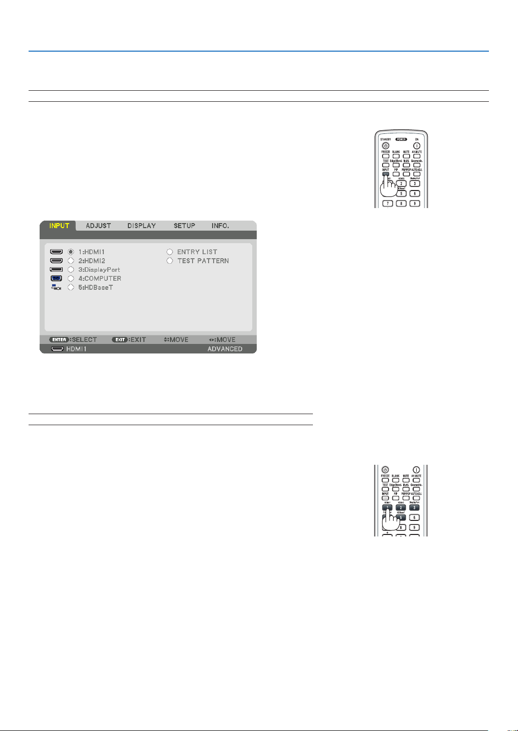
❹ Selecting a Source
Selecting the computer or video source
NOTE:Turnonthecomputerorvideosourceequipmentconnectedtotheprojector.
Detecting the Signal Automatically
PresstheINPUTbuttonfor1secondorlonger.Theprojectorwillsearch
fortheavailableinputsourceanddisplayit.Theinputsourcewillchange
as follows:
HDMI1→HDMI2→DisplayPort→COMUPTER→HDBaseT→HDMI1
→ …
•Pressitbrieytodisplaythe[INPUT]screen.
Press the ▼/▲buttonstomatchthetargetinputterminalandthenpress
theENTERbuttontoswitchtheinput.Todeletethemenudisplayin
the[INPUT]screen,presstheMENUorEXITbutton.
TIP:Ifnoinputsignalispresent,theinputwillbeskipped.
Using the Remote Control
Pressanyoneofthe1/HDMI1,2/HDMI2,3/DisplayPort,4/Computer,
or5/HDBaseTbutton.
19
2. Projecting an Image (Basic Operation)
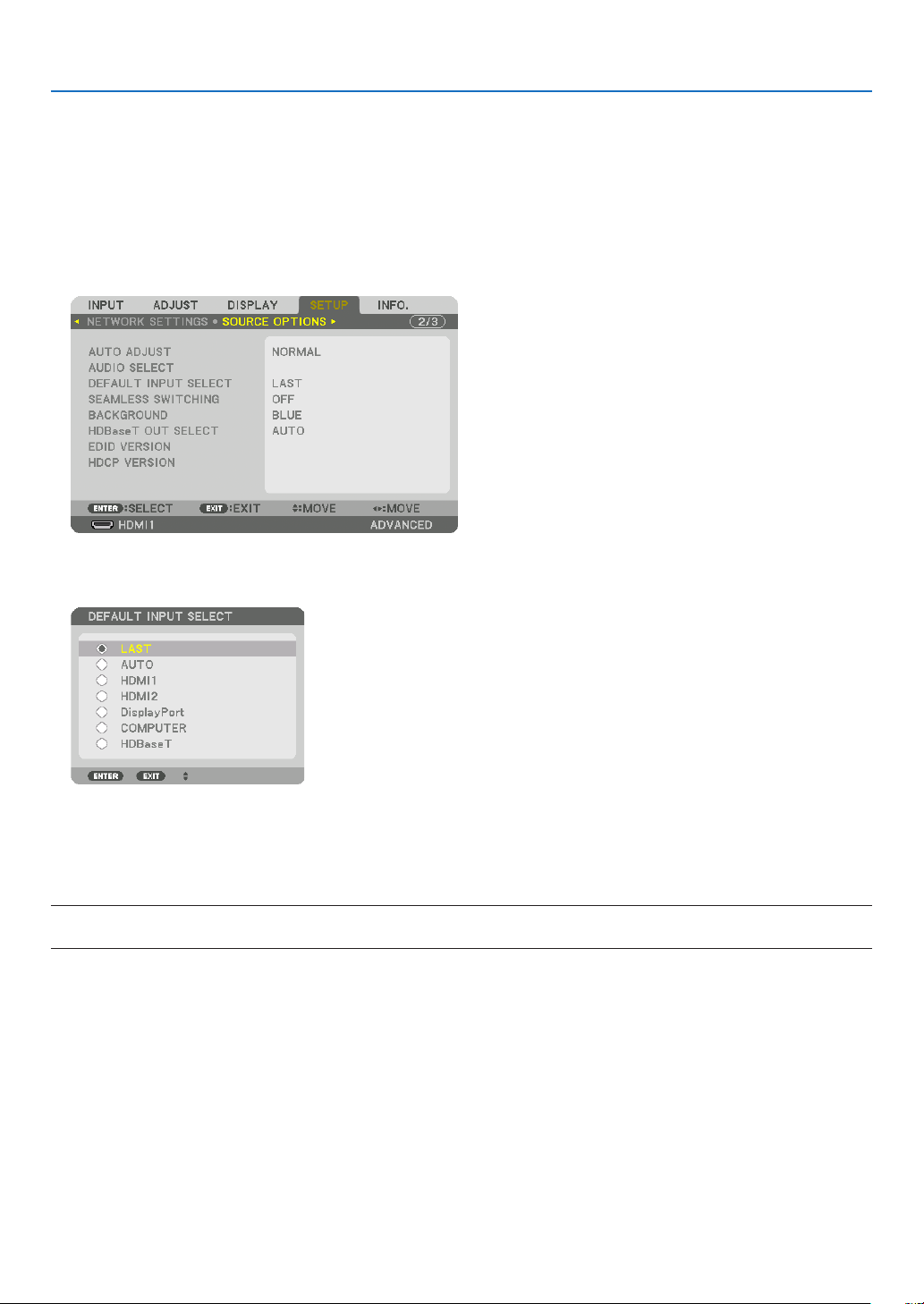
SelectingDefaultSource
Youcansetasourceasthedefaultsourcesothatitwillbedisplayedeachtimetheprojectoristurnedon.
1.PresstheMENUbutton.
The menu will be displayed.
2.Pressthe▶buttontoselect[SETUP]andpressthe▼buttonortheENTERbuttontoselect[BASIC].
3.Pressthe▶buttontoselect[SOURCEOPTIONS]andpressthe▼buttonortheENTERbutton.
4.Pressthe▼buttonthreetimestoselect[DEFAULTINPUTSELECT]andpresstheENTERbutton.
The [DEFAULT INPUT SELECT] screen will be displayed.
(→ page
128)
5.Selectasourceasthedefaultsource,andpresstheENTERbutton.
6.PresstheEXITbuttonafewtimestoclosethemenu.
7.Restarttheprojector.
The source you selected in step 5 will be projected.
NOTE:Evenwhen[AUTO]isturnedon,the[HDBaseT]willnotbeautomaticallyselected.Tosetyournetworkasthedefaultsource,
select[HDBaseT].
TIP:
•WhentheprojectorisinStandbymode,applyingacomputersignalfromacomputerconnectedtotheCOMPUTERINinputwill
powerontheprojectorandsimultaneouslyprojectthecomputer’simage.
([AUTOPOWERONSELECT]→page
130)
•OntheWindows7keyboard,acombinationoftheWindowsandPkeysallowsyoutosetupexternaldisplayeasilyandquickly.
20
2. Projecting an Image (Basic Operation)
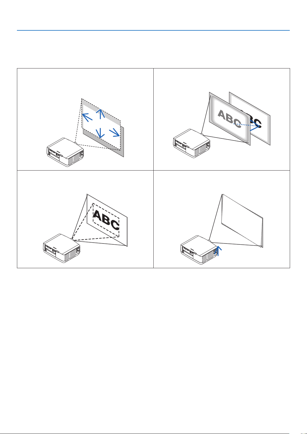
❺ Adjusting the Picture Size and Position
Usethelensshiftdial,theadjustabletiltfootlever,thezoomandthefocusringtoadjustthepicturesizeandposition.
In this chapter drawings and cables are omitted for clarity.
Adjustingtheprojectedimage’sverticalandhorizontal
position
[Lensshift]
(→page21)
Adjustingthefocus
[Focus]
(→page22)
Finelyadjustingthesizeofanimage
[Zoom]
(→page25)
Adjustingtheprojectedimage’sinclination
[Tiltfoot]
(→page26)
21
2. Projecting an Image (Basic Operation)
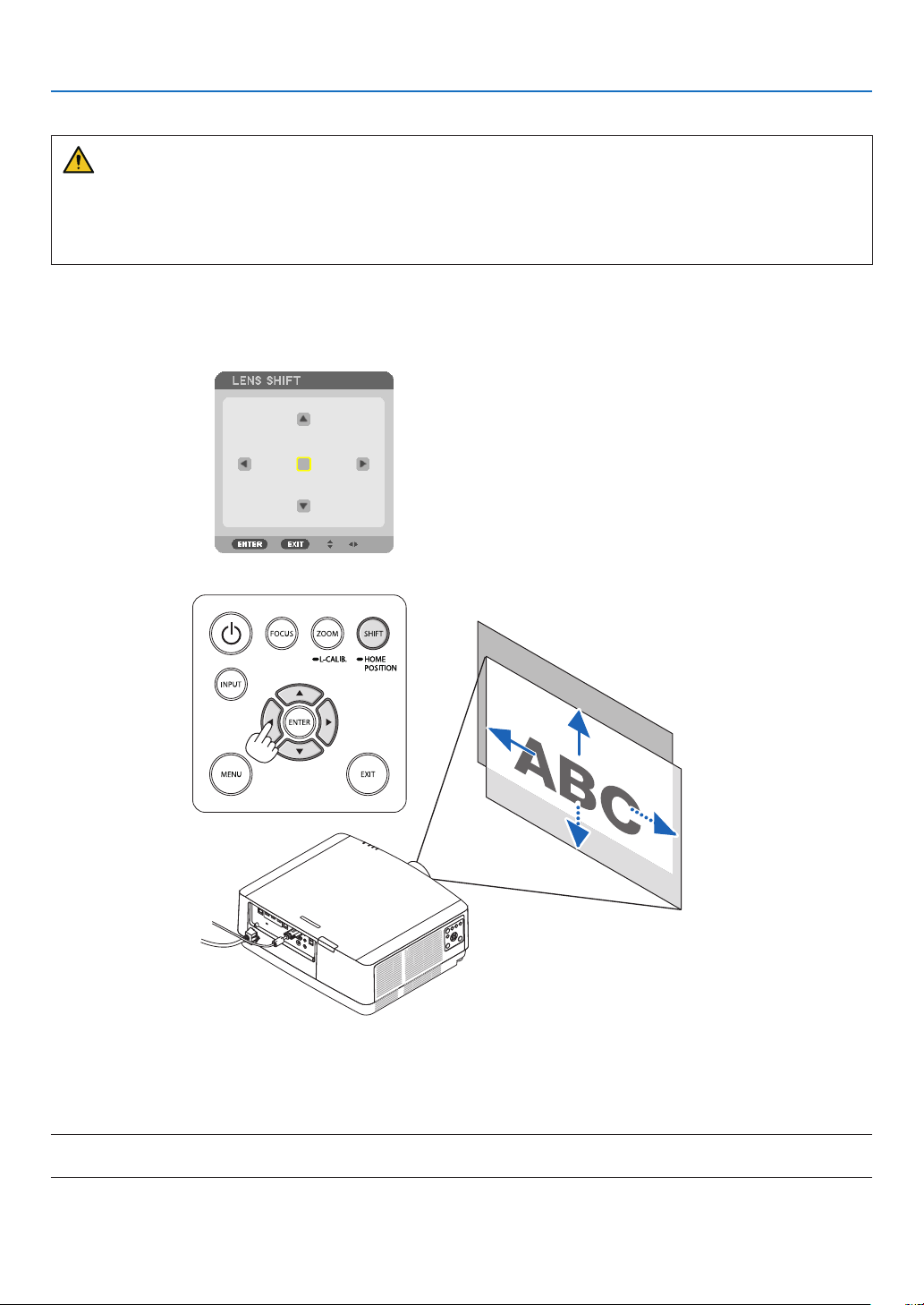
Adjusting the vertical position of a projected image (Lens shift)
CAUTION
•Performtheadjustmentfrombehindorfromthesideoftheprojector.Adjustingfromthefrontcouldexposeyour
eyestostronglightwhichcouldinjurethem.
•Keephandsawayfromthelensmountingportionwhileperformingalensshift.Failuretodosocouldresultin
ngersbeingpinchedbythemovinglens.
1.PresseitherSHIFT/HOMEPOSITIONbuttononthecabinetorLENS
SHIFTbuttonontheremotecontrol.
The [LENS SHIFT] screen will be displayed.
2.Pressthe▼▲◀▶buttonstomovetheprojectedimage.
•Tosetbackthelenstothehomeposition
Press and hold the SHIFT/HOME POSITION button over 2 seconds. The lens mounted on the projector goes
back to the home position. (roughly to the center position)
NOTE:
•Ifthelensisshiftedtothemaximuminthediagonaldirection,thescreenperipheralareawillbedarkorshaded.
22
2. Projecting an Image (Basic Operation)
TIP:
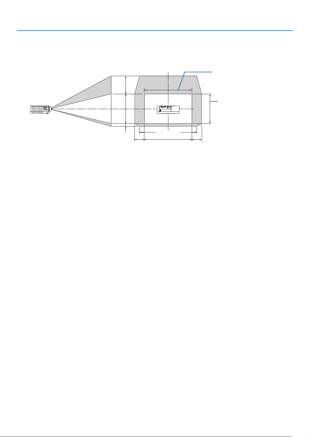
•Thediagrambelowshowsthelensshiftadjustmentrange(orientation:desk/front).
100%V
50%V
10%V
100%H
20%H
20%H
10%H10%H
Height of projected image
Width of projected image
Descriptionofsymbols:Vindicatesvertical(heightoftheprojectedimage),Hindicateshorizontal(widthoftheprojectedimage).
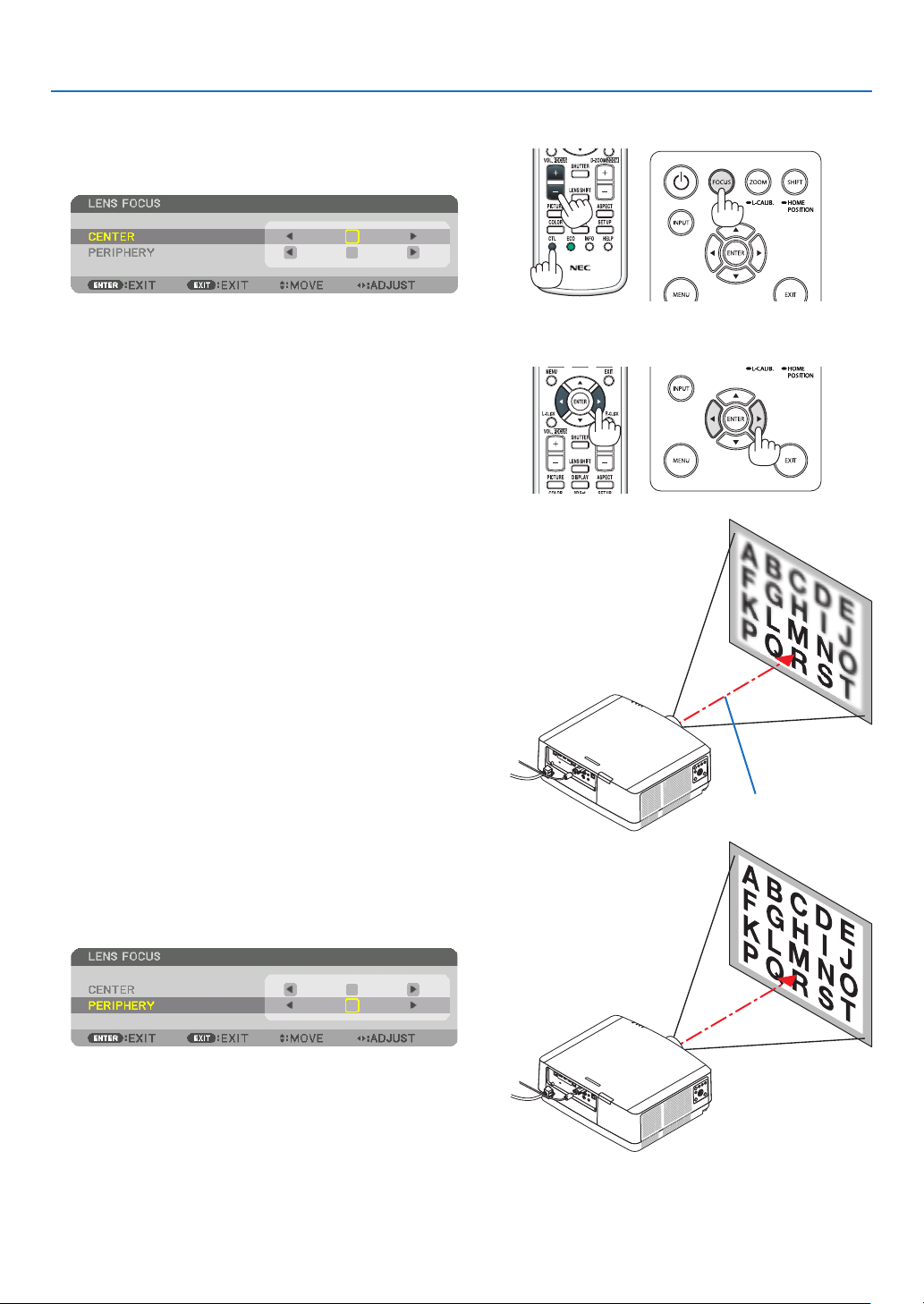
Focus
RecommendtoperformthefocusadjustmentafterleavingtheprojectorunderthestatetheTESTPATTERNhas
been projected for over 30 minutes.
Pleaserefertopage
85intheUser’sManualabouttheTESTPATTERN.
23
2. Projecting an Image (Basic Operation)
Applicablelens:NP40ZL/NP41ZL
1.PresstheFOCUSbuttononthecabinet.
The LENS FOCUS control screen will be displayed on.
* Press ◀▶ buttons to adjust focus. In another way, press
and hold the CTL button and then press VOL./FOCUS
+/− button on the remote control
2.WhenthecursorisontheCENTERonon-screenmenu,
press either ◀ or ▶buttontoalignfocusaroundthe
opticalaxis.
* The picture shows and example when the lens shift
is moved upward. The focus for the lower part of the
screen is aligned.
When the lens is at the center, the focus for the center
of the screen is aligned.
Optical axis
3.Press▼buttontoselectthePERIPHERYontheon-
screenmenu,andthenpresseither◀ or ▶buttonto
alignthefocusofscreenperipheralarea.Duringthis
operation,thefocusforaroundtheopticalaxiswillbe
maintained.
24
2. Projecting an Image (Basic Operation)
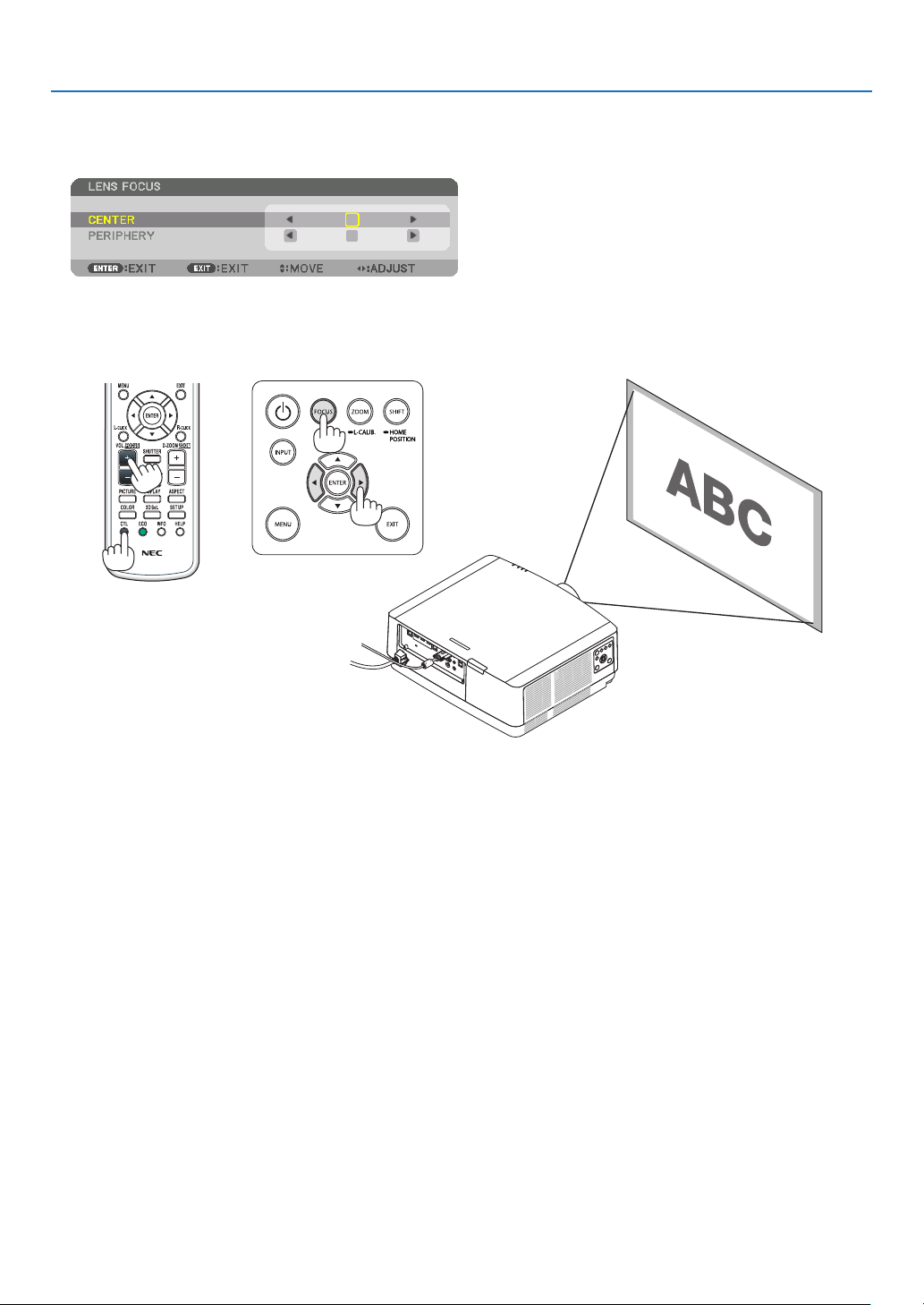
Applicablelens:NP42ZL
1.PresstheFOCUSbuttononthecabinet.
Press ◀▶ buttons to adjust focus. In another way, press and hold the CTL button and then press VOL./FOCUS
+/− button on the remote control.
* PERIPHERY LENS FOCUS is not available for this lens unit.
25
2. Projecting an Image (Basic Operation)
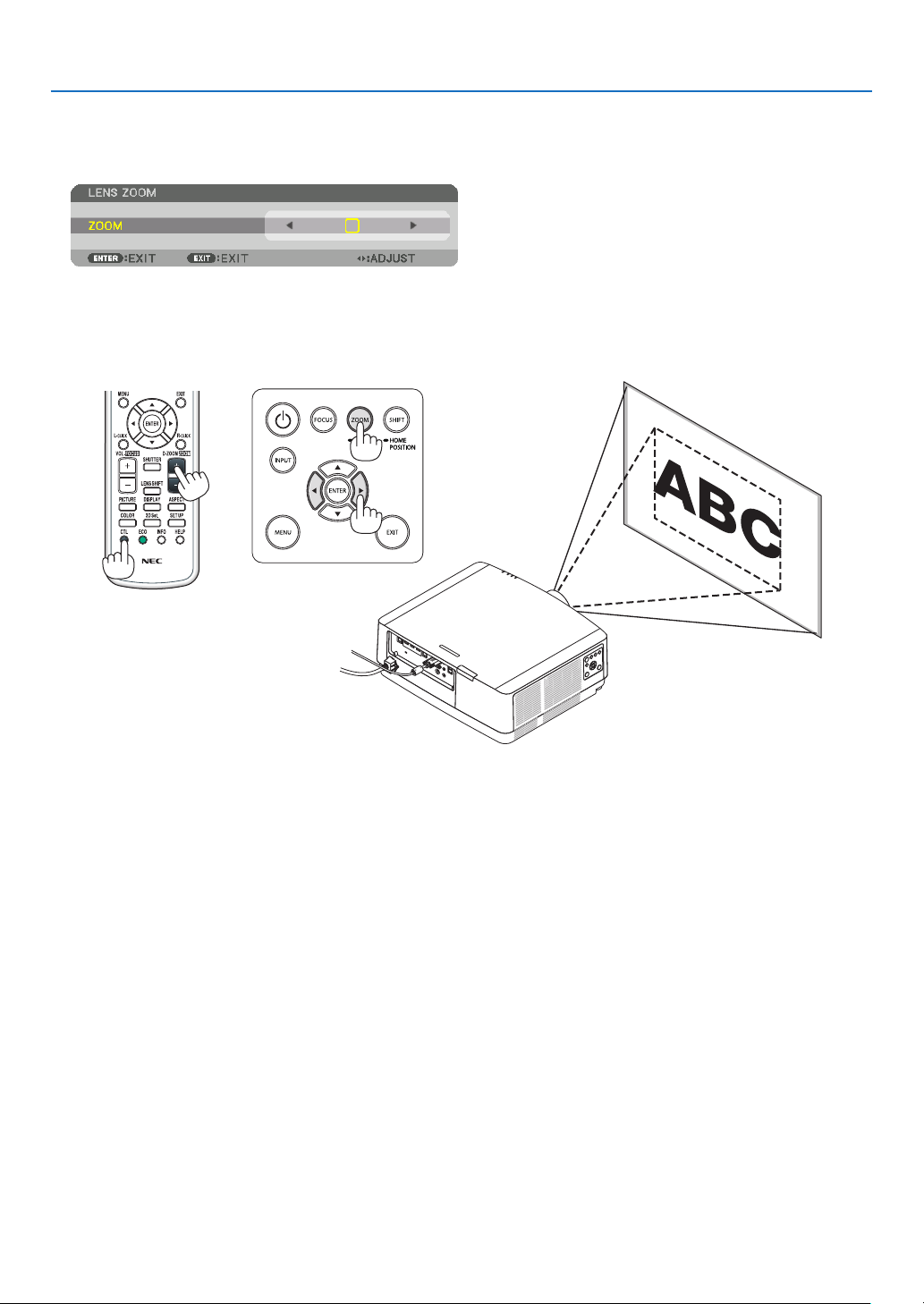
Zoom
1.PressZOOM/L-CALIB.button.
The ZOOM adjustment screen will be displayed on.
•◀ or ▶ buttons on the cabinet or the remote control are available to adjust ZOOM while the ZOOM adjustment
screen is displayed on.
•Ontheremotecontrol,whilepressingontheCTLbutton,presstheD-ZOOM/ZOOM(+)or(−)button.
The zoom is adjusted.
26
2. Projecting an Image (Basic Operation)
Adjusting the Tilt Foot
1.Turntheleftandrighttiltfoottoadjust.
The tilt foot lengthen and shorten when turned.
Turn one of the tilt foot to adjust the image so that it is level.
•Iftheprojectedimageisdistorted,see“3-7CorrectingHorizontal
and Vertical Keystone Distortion [CORNERSTONE]” (→ page
36)
and “[GEOMETRIC CORRECTION]” (→ page 101).
•Thetiltfootcanbelengthenedbyamaximumof10mm/0.4".
•Thetiltfootcanbeusedtotilttheprojectorbyamaximumof1.4°.
NOTE:
•Donotlengthenthetiltfootanymorethan10mm/0.4".Doingsowillmakethe
projectorunstable.
•Donotusethetiltfootforanypurposeotherthanadjustinginclinationofthe
projectorinstallationangle.
Handlingthetiltfootimproperly,suchascarryingtheprojectorbygraspingthe
tiltfootorhookingitontoawallusingthetiltfoot,coulddamagetheprojector.
Up
Tilt foot
Down
27
2. Projecting an Image (Basic Operation)
❻ Optimizing Computer Signal Automatically
Adjusting the Image Using Auto Adjust
Whenprojectingasignalfromthecomputervideoinputterminal,HDMI1INterminal,HDMI2INterminal,DisplayPort
INterminal,HDBaseTIN/Ethernetport,adjustthepicturequalitywithasingletouchofthebuttoniftheedgesofthe
screenarecutofforiftheprojectionqualityisbad.
PresstheAUTOADJ.buttontooptimizeacomputerimageautomatically.
Thisadjustmentmaybenecessarywhenyouconnectyourcomputerforthersttime.
[Poor picture] [Normal picture]
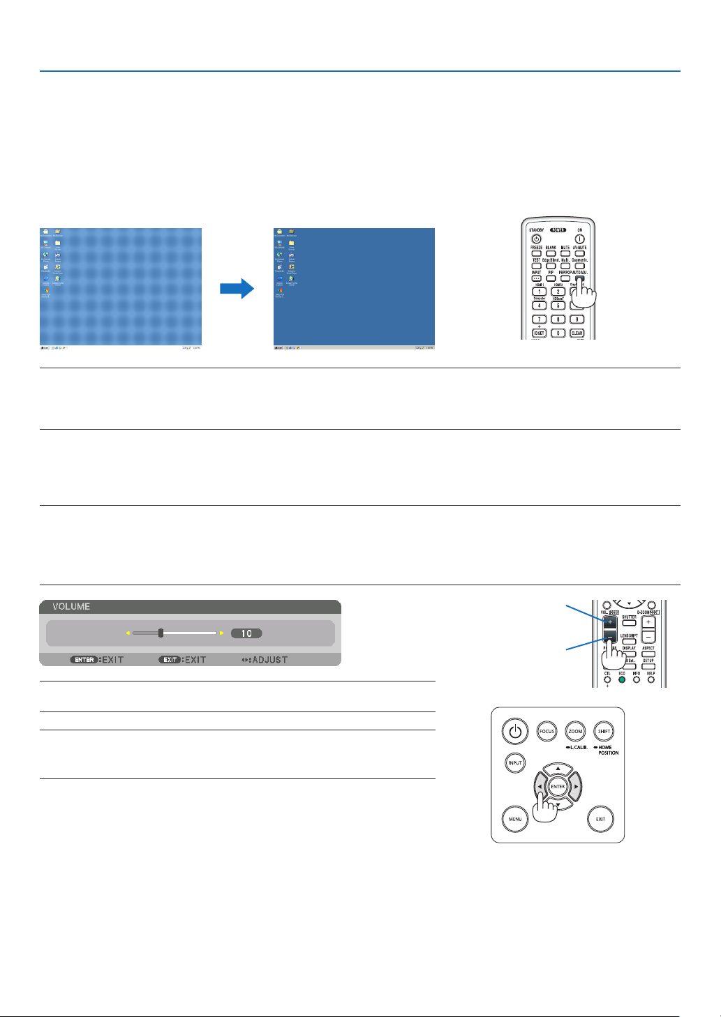
NOTE:
Somesignalsmaytaketimetodisplayormaynotbedisplayedcorrectly.
•IftheAutoAdjustoperationcannotoptimizethecomputersignal,trytoadjust[HORIZONTAL],[VERTICAL],[CLOCK],and[PHASE]
manually.(→page90,91)
❼ Turning Up or Down Volume
SoundlevelfromtheAUDIOOUTterminalcanbeadjusted.
Important:
•DonotturnupthevolumetothemaximumlevelontheexternalspeakersystemconnectedtotheAUDIOOUToftheprojector.
Doingsomayproduceanunexpected,loudsoundatthetimeofturningonorofftheprojector,causingdamagetoyourhearing.
Whenadjustingthevolumeontheexternalspeakersystem,setvolumelevelofthespeakersystemtolessthanhalfitsratingand
adjustthevolumeontheprojectortogetappropriatesoundlevel.
TIP:Whennomenusappear,the◀and▶buttonsontheprojectorcabinetwork
asavolumecontrol.
NOTE:
•Volumecontrolisnotavailablewiththe◀or▶buttonwhenanimageisenlarged
byusingtheD-ZOOM(+)buttonorwhenthemenuisdisplayed.
Increase volume
Decrease volume
28
2. Projecting an Image (Basic Operation)
❽ Turning off the Projector
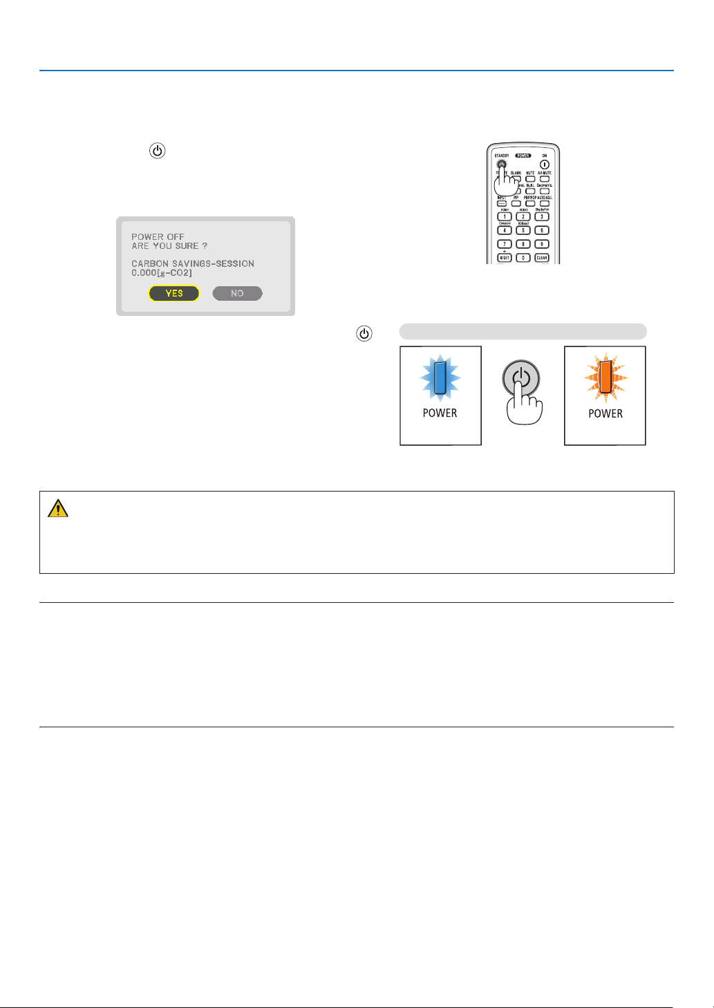
Toturnofftheprojector:
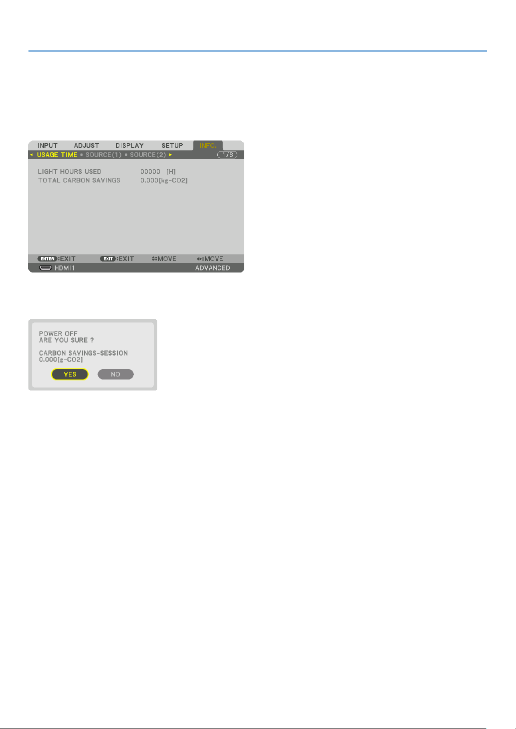
1.First,pressthe
(POWER)buttonontheprojector
cabinetortheSTANDBYbuttonontheremotecontrol.
The [POWER OFF / ARE YOU SURE ? / CARBON SAV-
INGS- SESSION 0.000[g-CO2]] message will appear.
2.Secondly,presstheENTERbuttonorpressthe
(POWER)ortheSTANDBYbuttonagain.
The light source will be turned off and the power supply will
be cut. The projector will go to sleep state and the POWER
indicator will light in green. If no operation is performed
on the projector and no signal is input to the projector,
the projector will be in standby state. The POWER indica-
tor will blilnk in orange (In the state, the standby mode is
NORMAL.).
Power On
Steadily lights in
blue
Standby
Blinks in orange
CAUTION:
PartsoftheprojectormaybecometemporarilyheatediftheprojectoristurnedoffwiththePOWERbuttonorifthe
ACpowersupplyisdisconnectedduringnormalprojectoroperation.
Usecautionwhenpickinguptheprojector.
NOTE:
•WhilethePOWERindicatorisblinkingblueinshortcycles,thepowercannotbeturnedoff.
•Youcannotturnoffthepowerfor60secondsimmediatelyafterturningitonanddisplayinganimage.
•Donotunplugthepowercordfromtheprojectororfromthepoweroutletwhileanimageisbeingprojected.Doingsocould
deterioratetheprojector’sACINterminalorthepowerplug’scontact.ToturnofftheACpowerwhileanimageisbeingprojected,
usethepowerstrip’sswitch,thebreaker,etc.
•DonotdisconnecttheACpowersupplytotheprojectorwithin10secondsofmakingadjustmentorsettingchangesandclosing
themenu.Doingsocancauselossofadjustmentsandsettings.
29
2. Projecting an Image (Basic Operation)
❾ After Use
Preparation:Makesurethattheprojectoristurnedoff.
1.Unplugthepowercord.
Loosen the screw coun-
terclockwise until it starts
racing.
Draw off the power cord
stopper.
2.Disconnectanyothercables.
3.Mountthelenscaponthelens.
4.Beforemovingtheprojector,screwinthetiltfootifthey
havebeenlengthened.
30
❶ Turn off the light of the projector (LENS SHUTTER)
PresstheSHUTTERbuttonontheremotecontrol.
Thelightsourcewillturnofftemporarily.
Pressagaintoallowthescreentobecomeilluminatedagain.
•Youcansettheprojectionlighttograduallyfadeinorout.
❷ Turning off the Image and Sound
Theprojectedvideoandtheoutputsoundfromthesoundoutputterminal
will disappear momentarily.
PresstheBLANKbutton.
Theprojectedvideowillbecutoff.
PresstheMUTEbutton.
Theaudiowillbecutoff.
PresstheAV-MUTEbutton.
Theprojectedvideoandaudiowillbecutoff.
•Pressthebuttonsonemoretimeforthecancelledvideoandaudioto
appearagain.
TIP:
•Thevideowilldisappearbutnotthemenudisplay.
3. Convenient Features
31
3. Convenient Features
❸ Shift the On-Screen Menu displaying position
1.PresstheMENUbutton.
The On-Screen Menu will be displayed on.
2.Movethecursorbythe▶buttontothe[SETUP]andthenpresstheENTERbutton.
The cursor will move to the [MENU(1)].
3.Movethecursorbythe▶buttontothe[MENU(2)].
4.Movethecursorbythe▼buttontothe[MENUPOSITION]andthenpresstheENTER.
The On-Screen Menu will go into the MENU POSITION setup screen.
5.Movethecursoreitherto[HORIZONTALPOSITION]or[VERTICALPOSITION]bypressing▼ or ▲button
andthenpress◀/▶buttontoshifttheOn-ScreenMenu.
For finishing the setting on the On-Screen Menu, press the MENU button on the remote control.
TIP:
•Oncetheprojectorispoweredoff,theOn-ScreenMenudisplayingpositionwillberesettothedefaultfactorysettingposition.
•Thisfunctiondoesnotinuencetothedisplaypositionofinputterminalinformationandmessage.
•ItenablestomovethemenubymouseclickwhenacommerciallyavailableUSBmouseisconnected.
•Itenablestomovethemenupositionbythe▼▲◀and▶buttonsholdingtopresstheCTLbuttonontheremotecontrolor
mouseclick.
•WhiletheMENUPOSITIONoftheon-screenmenuisdisplayedonandthemenuismovedbythe▼▲◀and▶buttonsholding
topresstheCTLbuttonontheremotecontrol,theindicationofadjustedvalueonthemenuwillnotbechanged.Inthiscase,
closetheMENUPOSITIONmenuonceanddisplayitagainforindicatingtheadjustedvalueproperly.
32
3. Convenient Features
❹ Freezing a Picture
PresstheFREEZEbuttontofreezeapicture.Pressagaintoresume
motion.
NOTE:Theimageisfrozenbuttheoriginalvideoisstillplayingback.
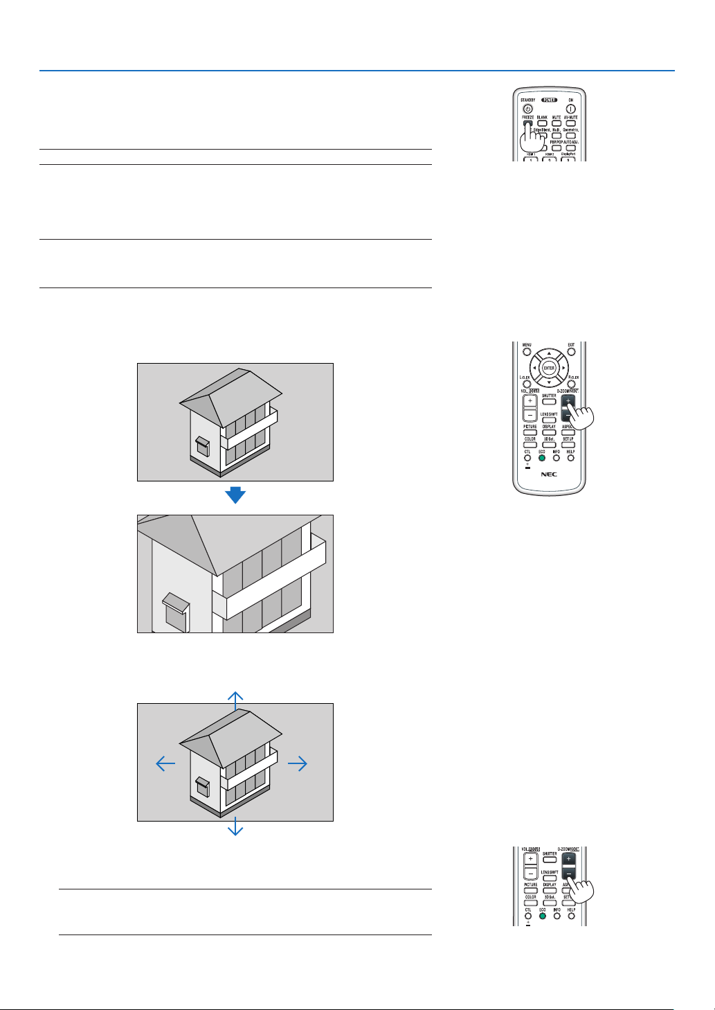
❺ Enlarging a Picture
Youcanenlargethepictureuptofourtimes.
NOTE:
•Dependingonaninputsignal,themaximummagnicationmaybelessthan
fourtimes,orthefunctionmayberestricted.
Todoso:
1.PresstheD-ZOOM(+)buttontomagnifythepicture.
2.Press the ▲▼◀▶button.
The area of the magnified image will be moved
3.PresstheD-ZOOM(−)button.
Each time the D-ZOOM (−) button is pressed, the image is reduced.
NOTE:
•Theimagewillbeenlargedorreducedatthecenterofthescreen.
•Displayingthemenuwillcancelthecurrentmagnication.
33
3. Convenient Features
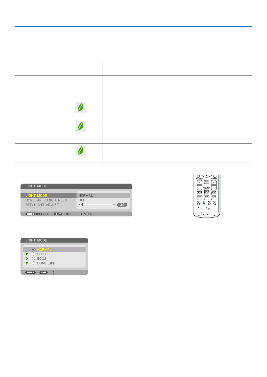
❻ Changing LIGHT MODE/Checking Energy-Saving Effect
Using LIGHT MODE [LIGHT MODE]
Wheneither[ECO1]or[ECO2]in[LIGHTMODE]isselected,motionnoiseoftheprojectoriscutdownbylowering
brightnessofitslightsource.
LIGHTMODE
Iconatthebottom
of the menu
Description
NORMAL
100%brightness
Thescreenwillbebrightlylit.
Dependingontheinstallationcircumstances,theservicelifeofoptical
parts may be shorten.
ECO1
Brightnesswillbeatabout80%.
Thecoolingfanwillalsoslowdownaccordingly.
Lower power consumption
ECO2
Brightnesswillbeatabout60%.
Thecoolingfanwillalsoslowdownaccordingly.
Lower power consumption considerably
Moreeco-friendlysettingthanNORMALandECO1.
LONGLIFE
Brightnessisabout30%.
Thissettingspeedsupthecoolingfanandoptimizestheservicelifeof
theopticalparts.Themosteco-friendlysettingamongtheoptions.
Toturnonthe[LIGHTMODE],dothefollowing:
1.PressECObuttonontheremotecontrol.
The [LIGHT MODE] screen will be displayed.
2.PresstheENTERbutton.
The [LIGHT MODE] selection screen will be displayed.
3.Usethe▼▲buttonstomakeaselection,andpresstheENTER
button.
The display will return to the [LIGHT MODE] screen and the selected
option will be applied.
Press the EXIT button to return to the original screen.

34
3. Convenient Features
NOTE:
•The[LIGHTMODE]canbechangedbyusingthemenu.
Select[SETUP]→[INSTALLATION(1)]→[LIGHTMODE]→[LIGHTMODE].
•Thelightmoduleusedhourscanbecheckedin[USAGETIME].Select[INFO.]→[USAGETIME].
•Afteralapseof1minutefromwhentheprojectordisplaysablue,blackorlogoscreen,theprojectorwillautomaticallylower
thebrightnesstotheequivalentlevelof[ECO2]when[NORMAL]or[ECO1]hasbeenselectedfor[LIGHTMODE]anditwillbe
automaticallybacktothepreviousbrightnesswhenitdetectsinputsignal.
•Iftheprojectorisoverheatedin[NORMAL]or[ECO1]mode,theremaybeacasetheprojectorautomaticallylowersthebright-
nessasaprotectivefunction.Thisiscalled“ForcedECOMODE”.WhentheprojectorisintheForcedECOMODE,thepicture
brightnessdecreasesslightlyandtheTEMP.indicatorlightsorange.AtthesametimetheThermometersymbol[]isdisplayed
atthebottomrightofthescreen.
Whentheambienttemperatureisloweredunderapprox33°,theForcedECOMODEiscancelledandtheprojectorgoesbackinto
thepreviouslysetstate.
35
3. Convenient Features
Checking Energy-Saving Effect [CARBON METER]
Thisfeaturewillshowenergy-savingeffectintermsofCO
2
emissionreduction(kg)whentheprojector’s[LIGHTMODE]
issettoeither[ECO1],[ECO2],or[LONGLIFE].Thisfeatureiscalledas[CARBONMETER].
Therearetwomessages:[TOTALCARBONSAVINGS]and[CARBONSAVINGS-SESSION].The[TOTALCARBON
SAVINGS]messageshowsthetotalamountofCO
2
emissionreductionfromthetimeofshipmentuptonow.Youcan
checktheinformationon[USAGETIME]from[INFO.]ofthemenu.(→page
133)
The[CARBONSAVINGS-SESSION]messageshowstheamountofCO
2
emission reduction between the time of
changingtoLIGHTMODEimmediatelyafterthetimeofpower-onandthetimeofpower-off.The[CARBONSAVINGS-
SESSION]messagewillbedisplayedinthe[POWEROFF/AREYOUSURE?]messageatthetimeofpower-off.
TIP:
•TheformulashownbelowisusedtocalculatetheamountofCO
2
emissionreduction.AmountofCO
2
emissionreduction=(Power
consumptionin[NORMAL]LIGHTMODE–Powerconsumptionincurrentsetting)×CO
2
conversionfactor.*Settingthe[LIGHT
MODE]to[ECO1],[ECO2],or[LONGLIFE]increasesCO
2
emissionssavings.
*CalculationforamountofCO
2
emissionreductionisbasedonanOECDpublication“CO
2
EmissionsfromFuelCombustion,
2008Edition”.
•The[TOTALCARBONSAVINGS]iscalculatedbasedonsavingsrecordedin15minutesintervals.
•Thisformulawillnotapplytothepowerconsumptionwhichisnotaffectedbywhether[LIGHTMODE]isturnedonoroff.
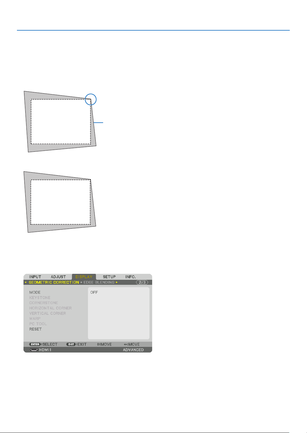
36
3. Convenient Features
❼ Correcting Horizontal and Vertical Keystone Distortion
[CORNERSTONE]
Usethe[CORNERSTONE]featuretocorrectkeystone(trapezoidal)distortiontomakethetoporbottomandtheleft
orrightsideofthescreenlongerorshortersothattheprojectedimageisrectangular.
1.Projectanimagesothatthescreenissmallerthantheareaoftheraster.
Projected image
The drawing shows the upper right corner.
2.Pickupanyoneofthecornersandalignthecorneroftheimagewithacornerofthescreen.
3.PresstheGeometric.buttoneitheronthecabinetortheremotecontrol.
Display the [GEOMETRIC CORRECTION] screen of the on-screen menu.
4.Movethecursoronto[MODE]by▼buttonandpresstheENTER.
The mode selection screen will displayed on.
5.Select[CORNERSTONE]andpresstheENTER.
Go back to display the [GEOMETRIC CORRECTION] screen of the on-screen menu.
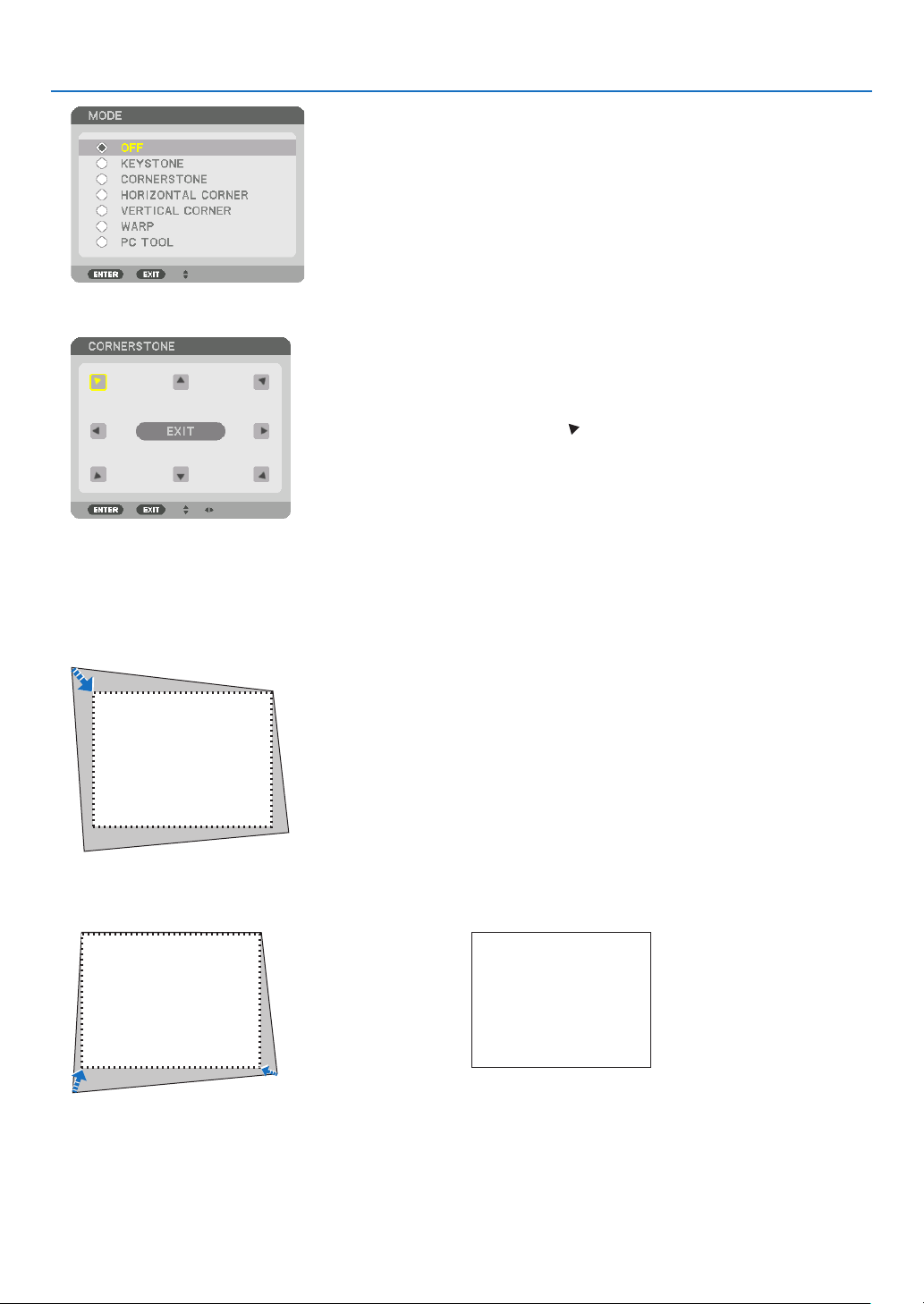
37
3. Convenient Features
6.Pressthe▼buttontoalignwiththe[CORNERSTONE]andthenpresstheENTERbutton.
The drawing shows the upper left icon ( ) is selected.
The screen will switch to the [CORNERSTONE] screen.
7.Usethe▲▼◀▶buttontoselectoneicon(▲)whichpointsinthedirectionyouwishtomovetheprojected
imageframe.
8.PresstheENTERbutton.
9.Usethe▲▼◀▶buttontomovetheprojectedimageframeasshownontheexample.
10
.PresstheENTERbutton.
11
.Usethe▲▼◀▶buttontoselectanothericonwhichpointsinthedirection.
On the [CORNERSTONE] screen, select [EXIT] or press the EXIT button on the remote control.

38
3. Convenient Features
The confirmation screen is displayed.
12
.Pressthe◀ or ▶buttontohighlightthe[OK]andpresstheENTERbutton.
This completes the [CORNERSTONE] correction.
•Select[CANCEL]andpresstheENTERbuttontoreturntothe[CORNERSTONE]screen.
Selecting[CANCEL]willreturntotheadjustmentscreenwithoutsavingchanges(Step3).
Selecting[RESET]willreturntothefactorydefault.
Selecting[UNDO]willexitwithoutsavingchanges.
NOTE:
•Evenwhentheprojectoristurnedon,thelastusedcorrectionvaluesareapplied.
•Carryouteitheroneofthefollowingactionstocleartheadjustmentvalueof[CORNERSTONE].
•InStep11,select[RESET]andthenpresstheENTERbutton.
•Inthestate[CORNERSTONE]hasbeenselectedfor[MODE]inthe[GEOMETRICCORRECTION]:
•PresstheGeometric.buttonfor2ormoreseconds.
•Run[DISPLAY]→[GEOMETRICCORRECTION]→[RESET]intheon-screenmenu.
•UsingCORNERSTONEcorrectioncancausetheimagetobeslightlyblurredbecausethecorrectionismadeelectronically.
•AcommerciallyavailableUSBmouseisavailableforCORNERSTONEcorrection.
❽ Operation for the On-Screen Menu by a commercially
available USB mouse
OnceacommerciallyavailableUSBmouseisconnectedtothisprojector,itenablestoperformtheoperationforthe
on-screenmenuandthegeometriccorrectioneasily.
NOTE:
•NotguaranteetheperformanceofallUSBmouseavailableonthemarket.
Menu operation
1.Displaytheon-screenmenubyrightclick.
2.Selectadesiredmenuandperformadjustmentbyleftclick.
The adjustment bar can be control by drag and drop.
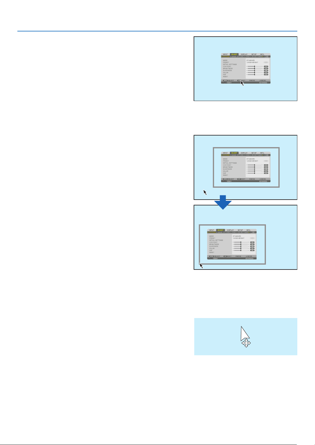
39
3. Convenient Features
3.Select[EXIT]displayedatthebottomofthemenubyleftclick
forgoingbacktothepreviouslevel.Ifthecursorisonthemain
menuoption,itworksforclosingthemenu.(Itworksasthesame
performancewiththe[EXIT]buttonontheremotecontrol.
Menu position control
1.Clickthewheelbuttontodisplaytheon-screenmenuindication
frame.
2.Leftclickatthepositionontheprojectionscreenwhereyouwant
toshifttheon-screenmenu.Thenearestcorneroftheon-screen
menuindicationframewillshifttotheclickedposition.
3.Clickthewheelbuttontoclosethemenuindicationframe.
Geometric correction
TheUSBmousecanbeusedforCORNERSTONECORRECTION,HORIZONTALCORNER,VERTICALCORNER
andWARP.Inthisclause,theCORNERSTONECORRECTIONbyanUSBmouseisexplainedasanexample.
1.WhiletheadjustmentscreenoftheCORNERSTONE
CORRECTIONisdisplayed,rightclickonthepro-
jectionscreen.Theshapeofmousepointerwillbe
changedandthecorrectionwillbecomeavailable.
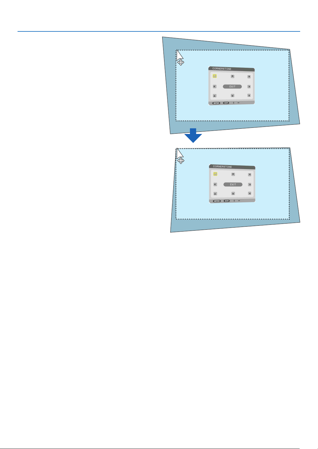
40
3. Convenient Features
2.Leftclickatthescreencorner.Theprojectionscreen
cornerwillmovetothemouseclickedposition.
3.Repeatthestep2forcorrectingalldistortion.After
completionofdistortioncorrection,rightclickon
theprojectionscreen.Theshapeofmousepointer
willbechangedtonormal.
4.Leftclick[EXIT]onthecorrectionscreentofinish.
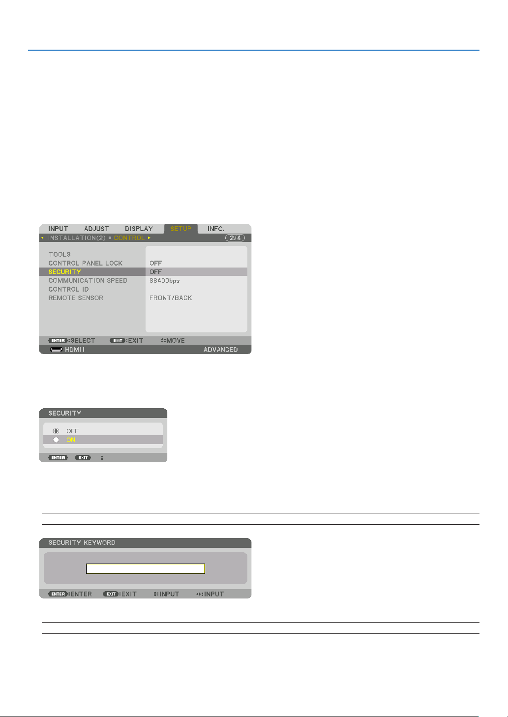
41
3. Convenient Features
❾
Preventing the Unauthorized Use of the Projector [SECURITY]
AkeywordcanbesetforyourprojectorusingtheMenutoavoidoperationbyanunauthorizeduser.Whenakeyword
isset,turningontheprojectorwilldisplaytheKeywordinputscreen.Unlessthecorrectkeywordisentered,thepro-
jectorcannotprojectanimage.
•The[SECURITY]settingcannotbecancelledbyusingthe[RESET]ofthemenu.
ToenabletheSecurityfunction:
1.PresstheMENUbutton.
The menu will be displayed.
2.Pressthe▶buttontwicetoselect[SETUP]andpressthe▼buttonortheENTERbuttontoselect[MENU(1)].
3.Pressthe▶buttontoselect[CONTROL].
4.Pressthe▼buttonthreetimestoselect[SECURITY]andpresstheENTERbutton.
The OFF/ON menu will be displayed.
5.Pressthe▼buttontoselect[ON]andpresstheENTERbutton.
The [SECURITY KEYWORD] screen will be displayed.
6.Typeinacombinationofthefour▲▼◀▶buttonsandpresstheENTERbutton.
NOTE:Akeywordmustbe4to10digitsinlength.
The [CONFIRM KEYWORD] screen will be displayed.
NOTE:Makeanoteofyourpasswordandstoreitinasafeplace.
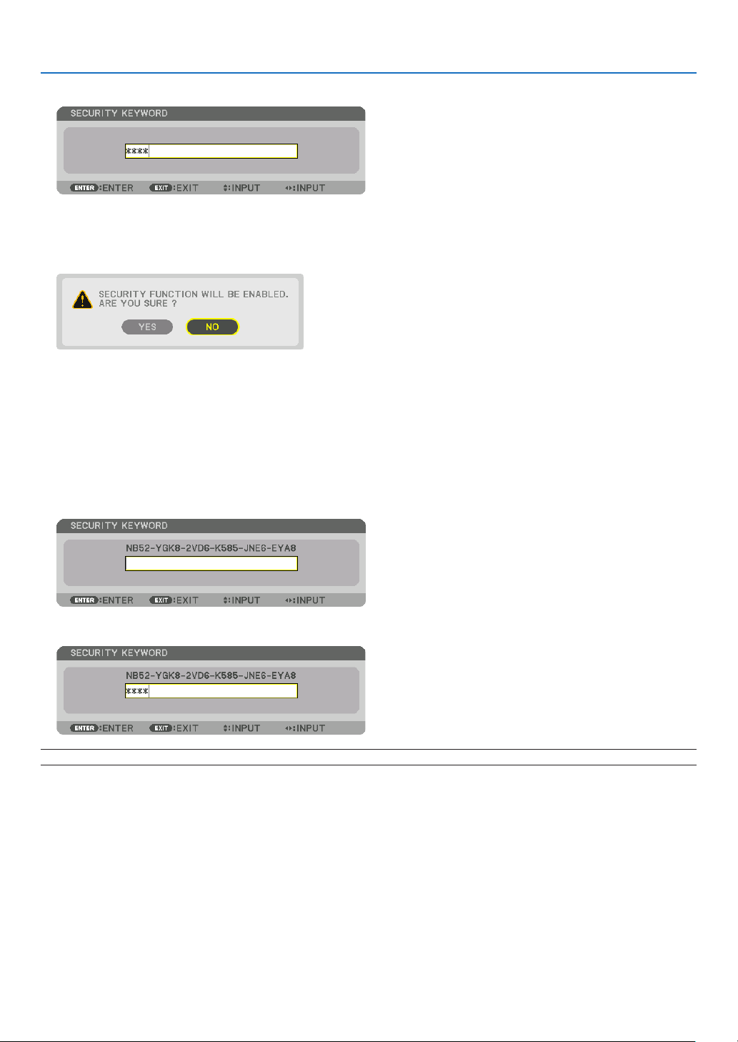
42
3. Convenient Features
7.Typeinthesamecombinationof▲▼◀▶buttonsandpresstheENTERbutton.
The confirmation screen will be displayed.
8.Select[YES]andpresstheENTERbutton.
The SECURITY function has been enabled.
Toturnontheprojectorwhen[SECURITY]isenabled:
1.PressthePOWERbutton.
The projector will be turned on and display a message to the effect that the projector is locked.
2.PresstheMENUbutton.
3.TypeinthecorrectkeywordandpresstheENTERbutton.Theprojectorwilldisplayanimage.
NOTE:Thesecuritydisablemodeismaintaineduntilthemainpoweristurnedofforunpluggingthepowercord.
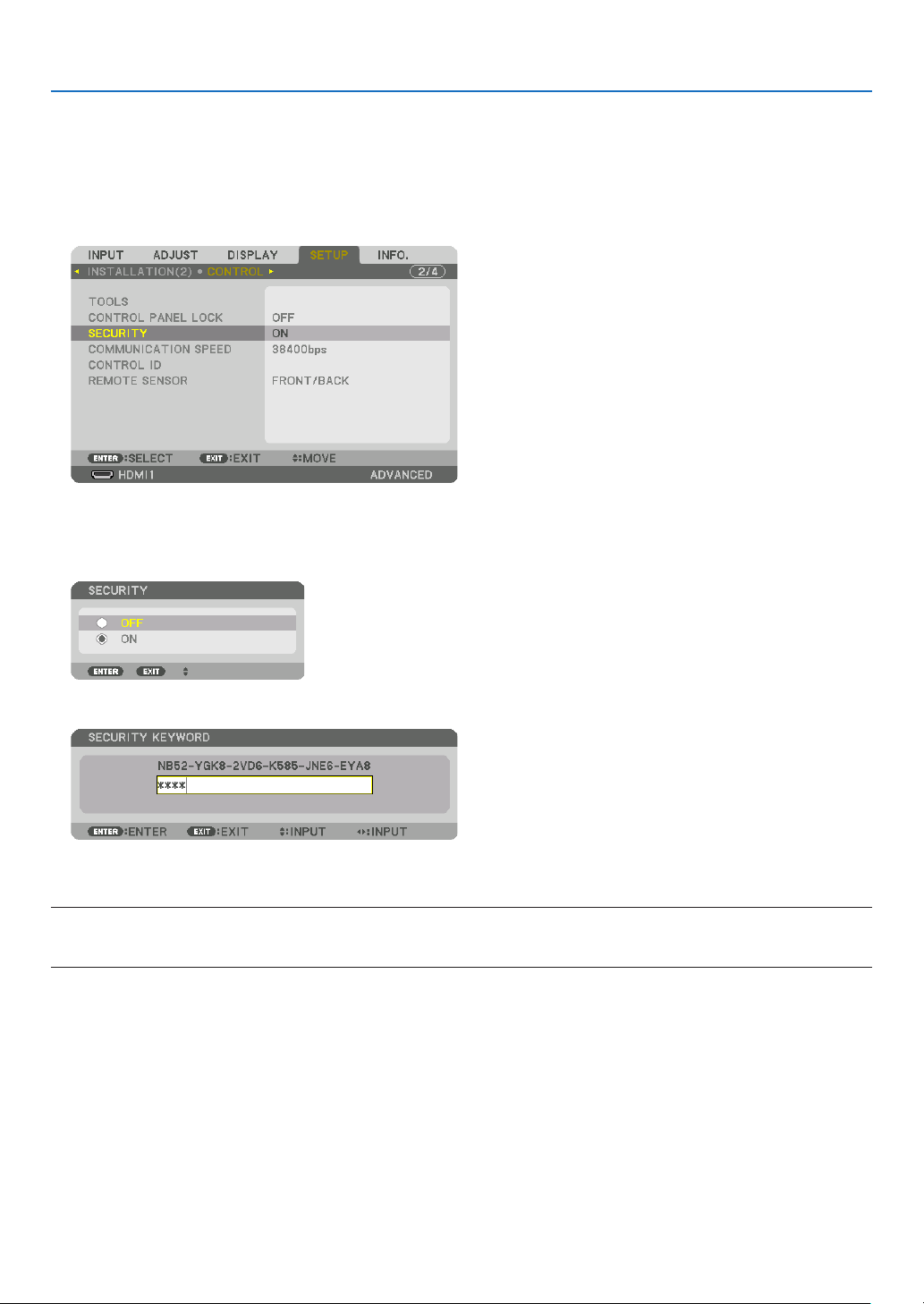
43
3. Convenient Features
TodisabletheSECURITYfunction:
1.PresstheMENUbutton.
The menu will be displayed.
2.Select[SETUP]→[CONTROL]→[SECURITY]andpresstheENTERbutton.
The OFF/ON menu will be displayed.
3.Select[OFF]andpresstheENTERbutton.
The SECURITY KEYWORD screen will be displayed.
4.TypeinyourkeywordandpresstheENTERbutton.
When the correct keyword is entered, the SECURITY function will be disabled.
NOTE:Ifyouforgetyourkeyword,contactyourdealer.Yourdealerwillprovideyouwithyourkeywordinexchangeforyourrequest
code.YourrequestcodeisdisplayedintheKeywordConrmationscreen.Inthisexample[NB52-YGK8-2VD6-K585-JNE6-EYA8]
isarequestcode.

44
3. Convenient Features
❿ Projecting 3D videos
Thisprojectorcanbeusedtowatchvideosin3Dusingcommercially-availableactiveshutter-type3Deyewear.In
ordertosynchronizethe3Dvideoandeyewear,acommercially-available3Demitterneedstobeconnectedtothe
projector (on the projector side).
The3Deyewearreceivesinformationfromthe3Demitterandperformsopeningandclosingontheleftandright.
CAUTION
Health precautions
Beforeuse,pleasemakesuretoreadanyhealthprecautionsthatmaybestatedintheoperatingmanualsenclosed
withthe3Deyewearand3Dvideosoftware(Blu-rayplayer,games,computeranimationles,etc.).
Pleasetakenoteofthefollowinginordertoavoidadversehealtheffects.
•Pleasedonotusethe3Deyewearforpurposesotherthantowatch3Dvideos.
•Pleasekeepadistanceofatleast2mawayfromthescreenwhenwatchingvideos.Watchingavideotooclose
tothescreenwillincreaseeyefatigue.
•Pleasedonotwatchvideoscontinuouslyforalongperiodoftime.Pleasetakea15minutes’breakafterevery
hourofwatching.
•Pleaseconsultadoctorbeforewatchingifyouoranyofyourfamilymembershaveahistoryofsufferingfrom
seizurescausedbylightsensitivity.
•Pleasestopwatchingimmediatelyandtakearestwhenyoufeelphysicallyunwellwhilewatching(vomiting,gid-
diness,nausea,headaches,soreeyes,blurredvision,crampsanddumbnessinthelimbs,etc.).Pleaseconsult
a doctor if the symptoms persist.
•Pleasewatcha3Dvideodirectlyinfrontofthescreen.Ifyouwatcha3Dvideoobliquelyfromthesides,this
mayresultinphysicalandeyefatigue.
3D eyewear and 3D emitter preparations
Pleaseuseanactiveshutter-type3DeyewearthatconformswiththeVESAstandard.
Acommercially-availableRFtypemadebyXpandisrecommended.
3D eyewear ............ Xpand X105-RF
3D emitter .............. Xpand AD025-RF-X1
Procedure to watch 3D videos using this projector
1.Connectthevideodevicetotheprojector.
2.Switchonthepowersupplytotheprojector.
3.Runthe3Dvideosoftwareandprojectthevideousingtheprojector.
This has been automatically set up when shipped from the factory. When a 3D video cannot be projected, it may
be because the 3D detection signals are not included or because they are not detectable by the projector.
Please manually select the format.
4.Selectthe3Dvideoformat.
(1) Press the “3D Set.” button on the remote control.

45
3. Convenient Features
The [3D SETTINGS] screen will be displayed.
(2) Press the ▼ button to align the cursor with the [FORMAT] and press the ENTER button.
The format screen will be displayed.
(3) Select the input signal format using the ▼ button and then press the ENTER button.
The 3D settings screen will disappear and the 3D video will be projected.
Press the MENU button and the on-screen menu will disappear.
The 3D caution message screen will be displayed when switching to a 3D video (default factory setting when
shipped). Please read the “Health Precautions” on the previous page to watch videos in the correct manner. The
screen will disappear after 60 seconds or when the ENTER button is pressed. (→ page
109)
5.Turnonthepowersupplyofthe3Deyewearandweartheeyeweartowatchthevideo.
A normal video will be shown when a 2D video is input.
To watch a 3D video in 2D, select [OFF(2D)] in the [FORMAT] screen mentioned above in (3).
NOTE:
•Uponswitchingto3Dimage,thefollowingfunctionswillbecancelledanddisabled.[BLANKING],[PIP/PICTUREBYPICTURE],
[GEOMETRICCORRECTION],[EDGEBLENDING]([GEOMETRICCORRECTION]and[EDGEBLENDING]adjustmentvalueswill
bemaintained.)
•Theoutputmaynotautomaticallyswitchtoa3Dvideodependingonthe3Dinputsignal.
•ChecktheoperatingconditionsdescribedintheusermanualoftheBlu-rayplayer.
•PleaseconnecttheDINterminalofthe3Demittertothe3DSYNCofthemainprojector.
•The3Deyewearallowsvideostobeviewedin3Dbyreceivingsynchronizedopticalsignalsoutputfromthe3Demitter.
Asaresult,the3Dimagequalitymaybeaffectedbyconditionssuchasthebrightnessofthesurroundings,screensize,viewing
distance,etc.
•Whenplayinga3Dvideosoftwareonacomputer,the3DimagequalitymaybeaffectedifthecomputerCPUandgraphicschip
performancearelow.Pleasechecktherequiredoperatingenvironmentofthecomputerthatisstatedintheoperatingmanual
attachedtothe3Dvideosoftware.
•Dependingonthesignal,[FORMAT]and[L/RINVERT]maynotbeabletobeselected.Pleasechangethesignalinthatcase.

46
3. Convenient Features
When videos cannot be viewed in 3D
Pleasecheckthefollowingpointswhenvideoscannotbeviewedin3D.
Pleasealsoreadtheoperatingmanualattachedtothe3Deyewear.
Possible reasons Solutions
The selected signal does not support 3D output. Please change the video signal input to one that supports 3D.
The format for the selected signal is turned to [OFF(2D)]. Please change the format in the on-screen menu to [AUTO] or a
format that supports 3D.
A eyewear that is not supported by the projector is being used. Please purchase a commercially-available 3D eyewear or 3D emitter
(recommended). (→ page
44)
Please check the following points when a video cannot be viewed in
3D using a 3D eyewear that is supported by the projector.
The power supply of the 3D eyewear is turned off. Please turn on the power supply of the 3D eyewear.
The internal battery of the 3D eyewear is flat. Please charge or replace the battery.
The viewer is located too far away from the screen. Please get closer to the screen until the video can be seen in 3D.
Please turn the L/R INVERT in the on-screen menu to [OFF].
Due to multiple 3D projectors working at the same time in the vi-
cinity, the projectors may interfere with one another. Alternatively,
there may be a bright light source near the screen.
Please maintain sufficient distance between the projectors.
Please keep the light source away from the screen.
Please turn the L/R INVERT in the on-screen menu to [OFF].
There is an obstacle between the optical receiver of the 3D eyewear
and the 3D emitter.
Please remove the obstacle.
The 3D format of the 3D video contents is not supported. Please check with the company selling the 3D video contents.

47
3. Convenient Features
⓫ Controlling the Projector by Using an HTTP Browser
Overview
Usingthewebbrowseronthecomputer,theHTTPserverscreenoftheprojectorcanbedisplayedtooperatethe
projector.
Possible operations on the HTTP server screen
•Congurethesettingsrequiredforconnectingtheprojectortothenetwork(wiredLAN).(NETWORKSETTINGS)
•Conguretheemailnotication.(ALERTMAIL)
Whentheprojectorisconnectedtoanetwork(wiredLAN),noticationsonvariouserrorsaresenttotheemail
address that has been set up.
•Operatetheprojector.
Operationssuchpoweron/offoftheprojector,inputterminalswitchover,volumecontrol,picturecontrol,andlens
control etc. can be carried out.
•Congurethe[PJLinkPASSWORD],[AMXBEACON],and[CRESTRON]etc.
To view the HTTP server screen
1.ConnecttheprojectortothecomputerwithaLANcablesoldcommercially.(→page
150)
2.Select[SETUP]→[NETWORKSETTINGS]→[WIREDLAN]intheon-screenmenutoconfigurethenetwork
settings.(→page
124)
3.StartupthewebbrowseronyourcomputerandentertheaddressorURLintheinputfield.
Specify the address or URL as “http://<IP Address of Projector>/index.html”.
The basic HTTP server screen will be displayed.
TIP:ThefactorysettingIPaddressis[DHCPON].
NOTE:
•Tousetheprojectorinanetwork,consultwithyournetworkadministratoraboutnetworksettings.
•Thedisplay’sorbutton’sresponsecanbesloweddownoroperationmaynotbeaccepteddependingthesettingsofyournetwork.
Shouldthishappen,consultyournetworkadministrator.Theprojectormaynotrespondifitsbuttonsarerepeatedlypressedin
rapidintervals.Shouldthishappen,waitamomentandrepeat.Ifyoustillcan’tgetanyresponse,turnoffandbackontheprojec-
tor.
•IfthePROJECTORNETWORKSETTINGSscreendoesnotappearinthewebbrowser,presstheCtrl+F5keystorefreshyourweb
browser(orclearthecache).
•Thisprojectoruses“JavaScript”and“Cookies”andthebrowsershouldbesettoacceptthesefunctions.Thesettingmethodwill
varydependingontheversionofbrowser.Pleaserefertothehelplesandtheotherinformationprovidedinyoursoftware.
Preparation before Use
ConnecttheprojectortoacommerciallyavailableLANcablebeforeengaginginbrowseroperations.(→page
150)
Operationwithabrowserthatusesaproxyservermaynotbepossibledependingonthetypeofproxyserverandthe
settingmethod.Althoughthetypeofproxyserverwillbeafactor,itispossiblethatitemsthathaveactuallybeenset
willnotbedisplayeddependingontheeffectivenessofthecache,andthecontentssetfromthebrowsermaynotbe
reectedinoperation.Itisrecommendedthataproxyservernotbeusedunlessitisunavoidable.
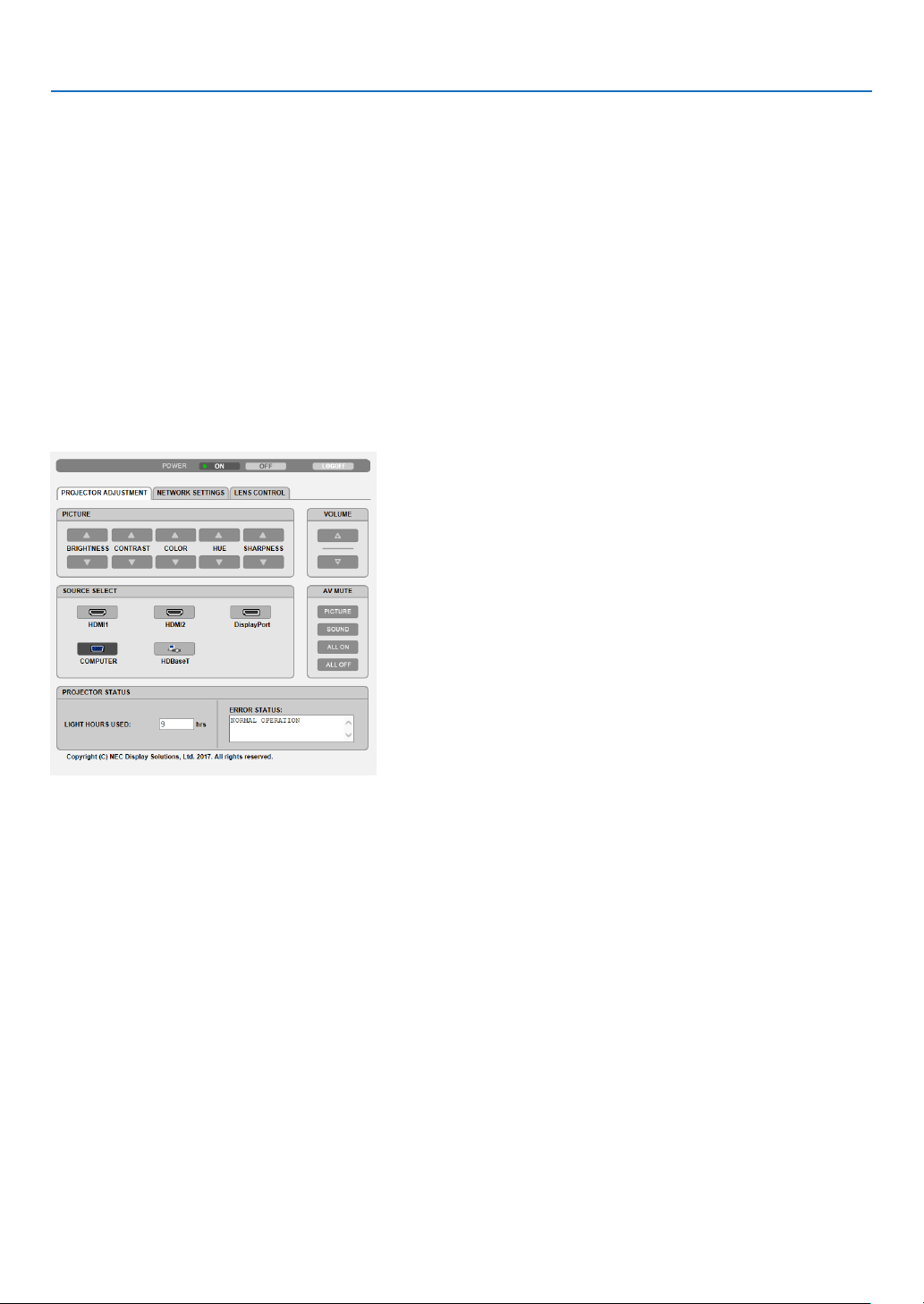
48
3. Convenient Features
Handling of the Address for Operation via a Browser
RegardingtheactualaddressthatisenteredfortheaddressorenteredtotheURLcolumnwhenoperationofthe
projectorisviaabrowser,thehostnamecanbeusedasitiswhenthehostnamecorrespondingtotheIPaddress
oftheprojectorhasbeenregisteredtothedomainnameserverbyanetworkadministrator,orthehostnamecor-
respondingtotheIPaddressoftheprojectorhasbeensetinthe“HOSTS”leofthecomputerbeingused.
Example1:Whenthehostnameoftheprojectorhasbeensetto“pj.nec.co.jp”,accessisgainedtothenetwork
settingbyspecifying
http://pj.nec.co.jp/index.html
fortheaddressortheentrycolumnoftheURL.
Example2:WhentheIPaddressoftheprojectoris“192.168.73.1”,accessisgainedtothenetworksettingby
specifying
http://192.168.73.1/index.html
fortheaddressortheentrycolumnoftheURL.
PROJECTOR ADJUSTMENT
POWER:Thiscontrolsthepoweroftheprojector.
ON ......................... Power is switched on.
OFF ........................ Power is switched off.
VOLUME:Thiscontrolsthevolumeoftheprojector.
▲ ........................... Increases the volume adjustment value for the AUDIO OUT terminal.
▼ ........................... Decreases the volume adjustment value for the AUDIO OUT terminal.
AV-MUTE:Thiscontrolsthemutefunctionoftheprojector.
PICTURE ON .......... Mutes the video.
PICTURE OFF ......... Cancels the video muting.
SOUND ON ............ Mutes the audio from the AUDIO OUT terminal.
SOUND OFF ........... Cancels the audio muting from the AUDIO OUT terminal.
ALL ON .................. Mutes each of the video, and audio functions for the AUDIO OUT terminal.
ALL OFF ................. Cancels the muting of each of the video, and audio functions for the AUDIO OUT terminal.

49
3. Convenient Features
PICTURE:Controlsthevideoadjustmentoftheprojector.
BRIGHTNESS ▲ .... Increases the brightness adjustment value.
BRIGHTNESS ▼ .... Decreases the brightness adjustment value.
CONTRAST ▲ ........ Increases the contrast adjustment value.
CONTRAST ▼ ........ Decreases the contrast adjustment value.
COLOR ▲ .............. Increases the color adjustment value.
COLOR ▼ .............. Decreases the color adjustment value.
HUE ▲ ................... Increases the hue adjustment value.
HUE ▼ ................... Decreases the hue adjustment value.
SHARPNESS ▲ ..... Increases the sharpness adjustment value.
SHARPNESS ▼ ..... Decreases the sharpness adjustment value.
•Thefunctionsthatcanbecontrolledwillvarydependingonthesignalbeinginputtotheprojector.(→page
88,
89)
SOURCESELECT:Thisswitchestheinputconnectoroftheprojector.
HDMI1 ................... Switches to the HDMI 1 IN connector.
HDMI2 ................... Switches to the HDMI 2 IN connector.
DisplayPort ............ Switches to the DisplayPort.
COMPUTER ........... Switches to the COMPUTER IN connector.
HDBaseT ................ Switch to image input sent from a transmission device that supports HDBaseT.
PROJECTORSTATUS:Thisdisplaystheconditionoftheprojector.
LIGHT HOURS USED ..........Displays how many hours the light module has been used.
ERROR STATUS ..................Displays the status of errors occurring within the projector.
LOGOFF:Loggingoffyourprojectorandreturningtotheauthenticationscreen(LOGONscreen).

50
3. Convenient Features
NETWORK SETTINGS
http://<IPAddressofProjector(Basic)>/index.html
•SETTINGS
WIRED LAN
INTERFACESelect[LAN]forconnectingLANbywirethrutheLANport.
Select[HDBaseT]forconnectingLANbywirethrutheHDBaseTIN/Ethernetport.
SETTINGSetforwiredLAN.
PROFILE1/PROFILE2TwosettingscanbesetforwiredLANconnection.SelectPROFILE1orPROFILE2.
DISABLETurnoffwiredLANconnection.ThePOWERindicatorthatisinformingtheSTANDBY
statewillstarttoblinkinorangelonginterval(→page165).
DHCPONAutomaticallyassignIPaddress,subnetmask,andgatewaytotheprojectorfromyour
DHCPserver.
DHCPOFFSetIPaddress,subnetmask,andgatewaytotheprojectorassignedbyyournetwork
administrator.
IPADDRESSSetyourIPaddressofthenetworkconnectedtotheprojector.
SUBNETMASKSetyoursubnetmasknumberofthenetworkconnectedtotheprojector.
GATEWAYSetthedefaultgatewayofthenetworkconnectedtotheprojector.
AUTODNSONDHCPserverwillautomaticallyassignIPaddressofDNSserverconnectedtothe
projector.
AUTODNSOFFSetyourIPaddressassignedbyyournetworkadministrator.
DNSSetyourIPaddressofDNSserverconnectedtotheprojector.
SAVEClickthisbuttontosaveyoursettingstotheprojector’smemory.
APPLYApplyyoursettingstowiredLAN.

51
3. Convenient Features
•NAME
PROJECTORNAMEEnteranameforyourprojectorsothatyourcomputercanidentifytheprojector.A
projector name must be 16 characters or less.
TIP:Projectornamewillnotbeaffectedevenwhen[RESET]isdonefromthemenu.
HOSTNAMEEnterthehostnameofthenetworkconnectedtotheprojector.Ahostnamemustbe
16 or less.
DOMAINNAMEEnterthedomainnameofthenetworkconnectedtotheprojector.Adomainname
must be 60 characters or less.
SAVE
Clickthisbuttontosaveyoursettingstotheprojector’smemory.
•ALERTMAIL
ALERTMAILThisoptionwillnotifyvariouserrorstoyourcomputerviae-mailwhenusingwiredLAN.
PlacingacheckmarkwillturnontheAlertMailfeature.
ClearingacheckmarkwillturnofftheAlertMailfeature.
Sampleofamessagetobesentfromtheprojector:
Subject:[Projector]ProjectorInformation
THECOOLINGFANHASSTOPPED.
[INFORMATION]
PROJECTORNAME:xxxxx
LIGHTHOURSUSED:xxxx[H]
SENDER’SADDRESSEntersender’saddress.
SMTPSERVERNAMEEntertheSMTPservernametobeconnectedtotheprojector.
RECIPIENT’SADDRESS
1,2,3
Enteryourrecipient’saddress.Uptothreeaddressescanbeentered.
TESTMAIL
Sendatestmailtocheckwhetheryoursettingsarecorrectornot
NOTE:
•Ifyouexecuteatest,youmaynotreceiveanAlertmail.Shouldthishappen,checkifnetwork
settingsarecorrect.
•Ifyouenteredanincorrectaddressinatest,youmaynotreceiveanAlertmail.Shouldthis
happen,checkiftheRecipient’sAddressiscorrect.
SAVEClickthisbuttontosaveyoursettingstotheprojector’smemory.

52
3. Convenient Features
•NETWORKSERVICE
PJLinkPASSWORDSetapasswordforPJLink*.Apasswordmustbe32charactersorless.Donotforget
yourpassword.However,ifyouforgetyourpassword,consultwithyourdealer.
HTTPPASSWORDSetapasswordforHTTPserver.Apasswordmustbe10charactersorless.
Whenapasswordissetup,youwillbepromptedforyourusername(arbitrary)and
passwordduringLOGON.
AMXBEACONTurnonorofffordetectionfromAMXDeviceDiscoverywhenconnectingtothenetwork
supportedbyAMX’sNetLinxcontrolsystem.
TIP:
WhenusingadevicethatsupportsAMXDeviceDiscovery,allAMXNetLinxcontrolsystemwill
recognizethedeviceanddownloadtheappropriateDeviceDiscoveryModulefromanAMXserver.
PlacingacheckmarkwillenabledetectingtheprojectorfromAMXDeviceDiscovery.
ClearingacheckmarkwilldisabledetectingtheprojectorfromAMXDeviceDiscovery.
ExtronXTPSetforconnectingthisprojectortotheExtronXTPtransmitter.Placingacheckmark
willenabletoconnectwiththeXTPtransmitter.Clearingacheckmarkwilldisableto
connectwiththeXTPtransmitter.
SAVEClickthisbuttontosaveyoursettingstotheprojector’smemory.
NOTE:Ifyouforgetyourpassword,contactyourdealer.Pleasecheck24digitsserialnumber(XXXX-XXXX-XXXX-XXXX-XXXX-XXXX)
displayedonthecolumnforthepassword.
*WhatisPJLink?
PJLinkisastandardizationofprotocolusedforcontrollingprojectorsofdifferentmanufacturers.Thisstandard
protocolisestablishedbyJapanBusinessMachineandInformationSystemIndustriesAssociation(JBMIA)in2005.
TheprojectorsupportsallthecommandsofPJLinkClass1.
SettingofPJLinkwillnotbeaffectedevenwhen[RESET]isdonefromthemenu.
•CRESTRON
ROOMVIEWformanagingfromthecomputer.
DISABLEDisablesROOMVIEW.
ENABLEEnablesROOMVIEW.
CRESTRONCONTROLformanagingfromthecontroller.
DISABLEDisablesCRESTRONCONTROL.
ENABLEEnablesCRESTRONCONTROL.
IPADDRESSSetyourIPaddressofCRESTRONSERVER.
IPIDSetyourIPIDofCRESTRONSERVER.
SAVEClickthisbuttontosaveyoursettingstotheprojector’smemory.
TIP:TheCRESTRONsettingsarerequiredonlyforusewithCRESTRONROOMVIEW.
Formoreinformation,visit
http://www.crestron.com
•INFORMATION
WIREDLANDisplayalistofsettingsofwiredLANconnection.
UPDATEReectsettingswhentheyarechanged.
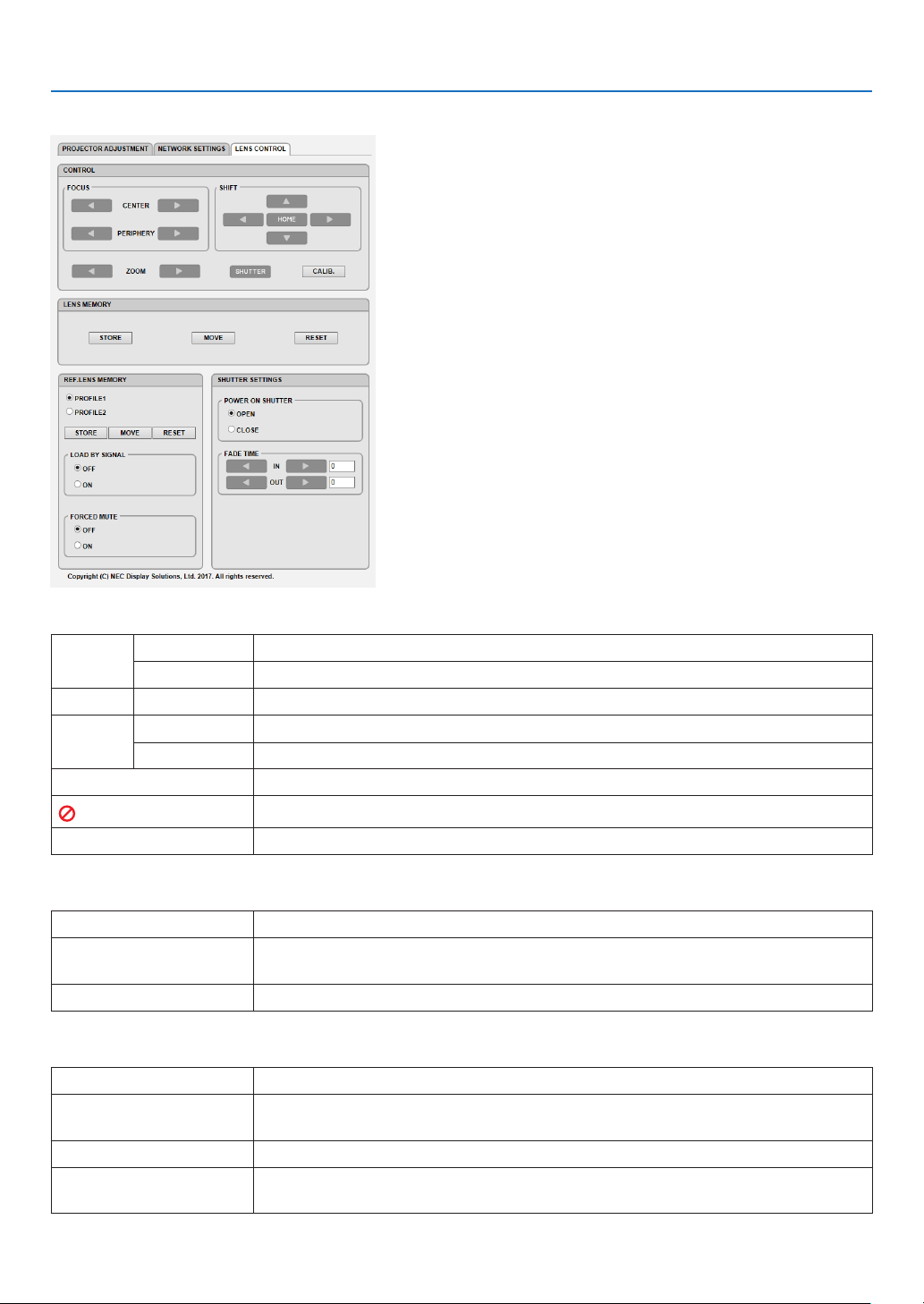
53
3. Convenient Features
LENS CONTROL
•CONTROL
FOCUSCENTERAlignthefocusaroundtheopticalaxis.
PERIPHERYAlignthefocusforthescreenperipheralarea.
ZOOM
◀/▶
Finelyadjustingthesizeofanimage.
SHIFT
▼▲◀▶
Adjusttheprojectedimage’sverticalandhorizontalposition.
HOMEReturnthelensshiftpositiontothehomeposition.
SHUTTERTurnoffthelightsourcetemporarily.
SHUTTER
Turnonthelightsource.
CALIB.Correcttheadjustablezoom,focusandlesshiftrange.
•LENSMEMORY
STOREStorethecurrentadjustedvaluesinmemoryforeachinputsignal.
MOVEAppliestheadjustedvaluesofLENSSHIFT,ZOOM,andFOCUStothecurrent
signal.
RESET
Returntheadjustedvaluedtothelastcondition.
•REF.LENSMEMORY
PROFILE1/PROFILE2Selectastored[PROFILE]number.
STOREStoreeachadjustedvalueofLENSSHIFT,ZOOMandFOCUSfortheselected
proleasthecommonvaluesforeveryinputsignal.
MOVEMovethelenstothestoredvaluesfortheselectedprole.
RESETResetselected[REF.LENSMEMORY]fortheselected[PROFILE]tothedefault
factorysettings.

54
3. Convenient Features
LOADBY
SIGNAL
OFFIfinputsignalisswitched,thelenswillnotshifttothelesshift,zoomandfocusval-
uesfortheselected[PROFILE]number.
ONIfinputsignalisswitched,thelenswillshifttothevaluesfortheselected[PROFILE]
number.
Ifnoadjustedvalueshavebeenstoredto[LENSMEMORY],thelenswillapply
[REF.LENSMEMORY]adjustedvalues.Alternatively,ifnoadjustedvalueshave
beenstoredto[REF.LENSMEMORY],thelenswillstayunmoved.
FORCED
MUTE
OFFNotturnofftheimageduringlesshift.
ONTurnofftheimageduringlesshift.
•SHUTTERSETTINGS
POWERON
SHUTTER
OPENWhenthepoweristurnedon,thelightsourcecomesonandthepictureisprojected.
CLOSEThelightsourcedoesnotcomeonwhenthepoweristurnedon.
WhentheSHUTTERbuttonispressed,theshutterisreleasedandthelightsource
is turned on.
FADETIMEINSethowlongthelightwilltaketofadeinaftertheSHUTTERbuttonispressed.
Thetimecanbesetfrom0to10secondsinincrementsof1second.
OUTSethowlongthelightwilltaketofadeoutaftertheSHUTTERbuttonispressed.
Thetimecanbesetfrom0to10secondsinincrementsof1second.
⓬ Storing Changes for Lens Shift, Zoom, and Focus [LENS
MEMORY]
ThisfunctionservestostoretheadjustedvalueswhenusingtheLENSSHIFT,ZOOMandFOCUSbuttonsofthepro-
jector.Adjustedvaluescanbeappliedtothesignalyouselected.Thiswilleliminatetheneedtoadjustlensshift,focus,
andzoomatthetimeofsourceselection.Therearetwowaystosaveadjustedvaluesforlensshift,zoom,andfocus.
FunctionnameDescriptionpage
REF.LENSMEMORYAdjustedvaluescommontoallinputsignals.Atthetimeofinstallation,
twokindsofadjustedvaluescanbestored.
Ifnoadjustedvalueshavebeensavedto[LENSMEMORY],thelens
willapply[REF.LENSMEMORY]adjustedvalues.
→page
114
LENSMEMORYAdjustedvaluesforeachinputsignal.
Usetheadjustedvaluesforthesignalwithadifferentaspectratioor
resolution.Theadjustedvaluescanbeappliedatthetimeofsource
selection.
→page
97
NOTE:
•Besuretocarryout[LENSCALIBRATION]afterreplacingthelens.
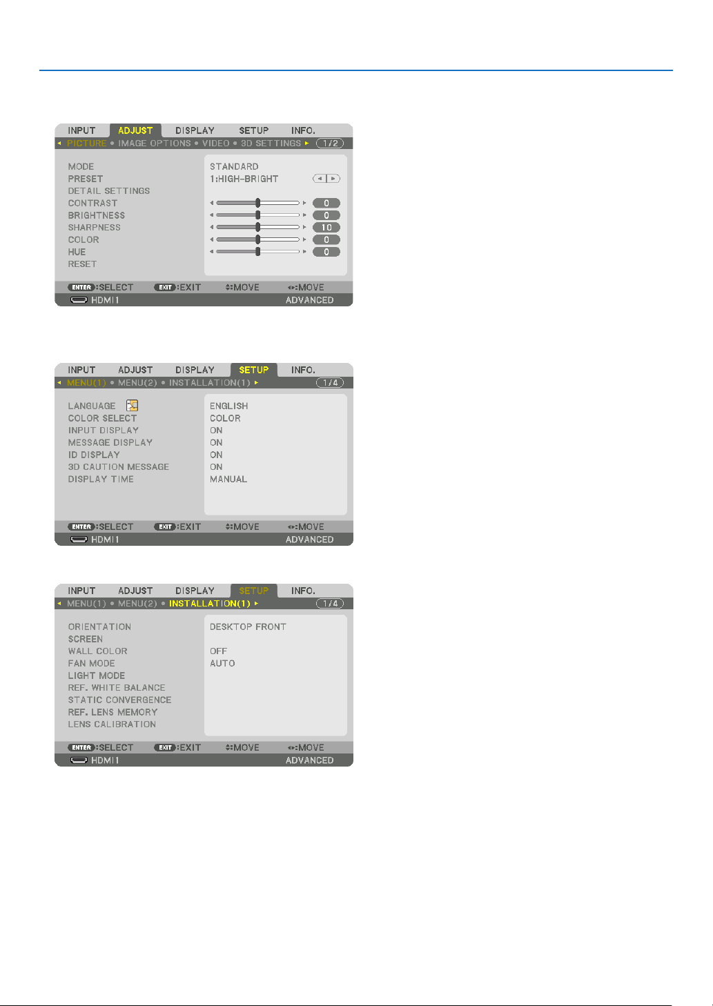
55
3. Convenient Features
To store your adjusted values in [REF. LENS MEMORY]:
1.PresstheMENUbutton.
The menu will be displayed.
2.Pressthe▶buttontoselect[SETUP]andpresstheENTERbutton.
3.Pressthe▶buttontoselect[INSTALLATION(1)].
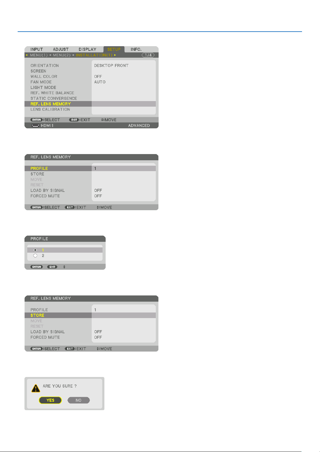
56
3. Convenient Features
4.Pressthe▼buttontoselect[REF.LENSMEMORY]andpresstheENTERbutton.
The [REF. LENS MEMORY] screen will be displayed.
5.Makesure[PROFILE]ishighlighted,thenpresstheENTERbutton.
The [PROFILE] selection screen appears.
6.Pressthe▼/▲buttonstoselectthe[PROFILE]number,thenpresstheENTERbutton.
Return to the [REF. LENS MEMORY] settings screen.
7.Select[STORE]andpresstheENTERbutton.
The confirmation screen will be displayed.
8.Pressthe◀buttontoselectand[YES]andpresstheENTERbutton.
Select a [PROFILE] number and save the adjusted [LENS SHIFT], [ZOOM], and [FOCUS] values to it.
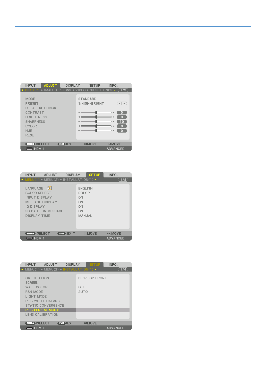
57
3. Convenient Features
9.PresstheMENUbutton.
The menu will be closed.
TIP:
•Tostoreadjustedvaluesforeachinputsource,usetheLensMemoryfunction.(→page
97)
To call up your adjusted values from [REF. LENS MEMORY]:
1.PresstheMENUbutton.
The menu will be displayed.
2.Pressthe▶buttontoselect[SETUP]andpresstheENTERbutton.
3.Pressthe▶buttontoselect[INSTALLATION(1)].
4.Pressthe▼buttontoselect[REF.LENSMEMORY]andpresstheENTERbutton.
The [REF. LENS MEMORY] screen will be displayed.
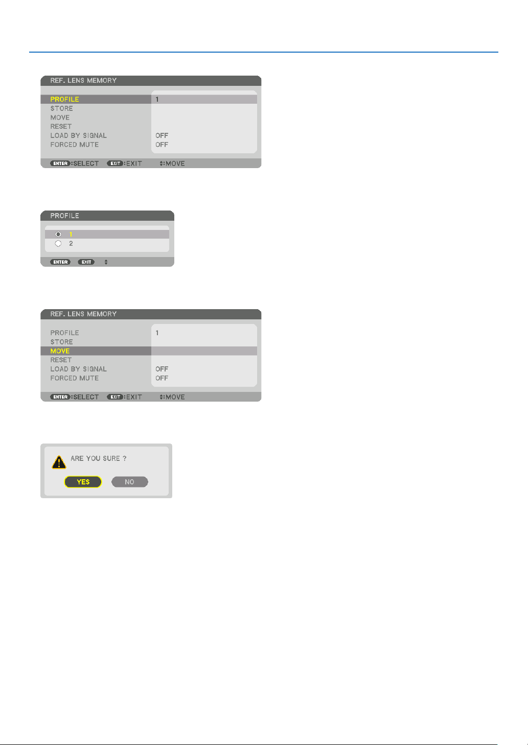
58
3. Convenient Features
5.Makesure[PROFILE]ishighlighted,thenpresstheENTERbutton.
The [PROFILE] selection screen appears.
6.Pressthe▼/▲buttonstoselectthe[PROFILE]number,thenpresstheENTERbutton.
Return to the [REF. LENS MEMORY] settings screen.
7.Select[MOVE]andpresstheENTERbutton.
The lens will shift based on the adjusted values stored in the selected [PROFILE].
8.Pressthe◀buttontoselectand[YES]andpresstheENTERbutton.
The adjusted values will be applied to the current signal. .
9.PresstheMENUbutton.
The menu will be closed.
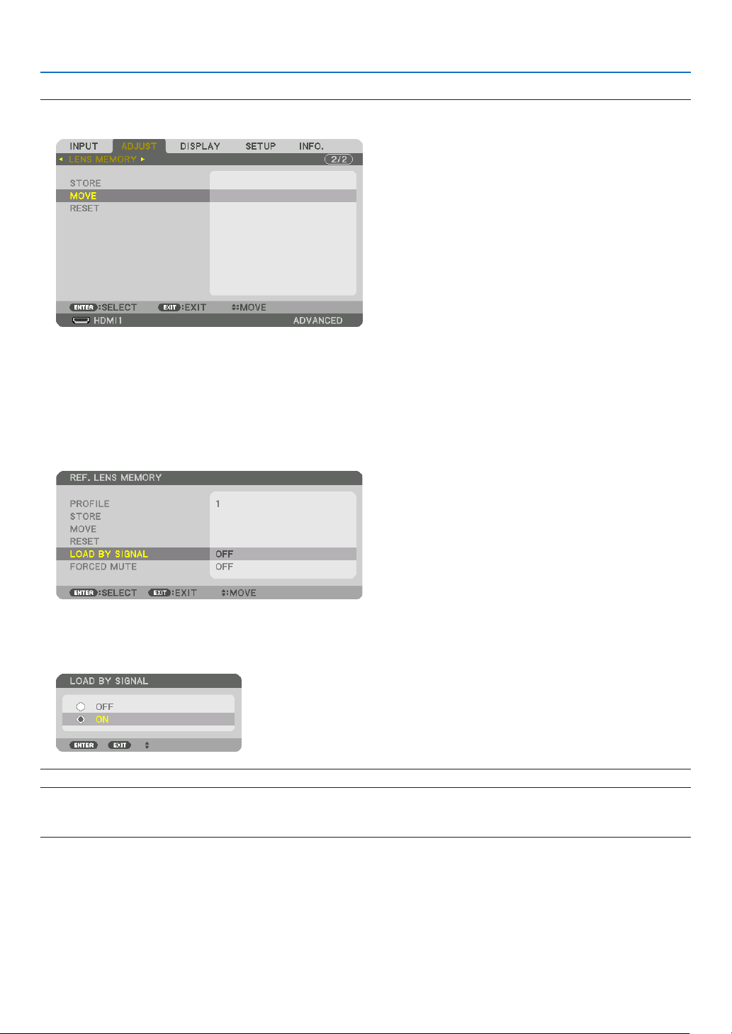
59
3. Convenient Features
TIP:
Tocallupthestoredvaluesfrom[LENSMEMORY]:
1.Fromthemenu,select[ADJUST]→[LENSMEMORY]→[MOVE]andpresstheENTERbutton.
The confirmation screen will be displayed.
2.Pressthe◀buttontoselectand[YES]andpresstheENTERbutton.
During projection, if the adjusted values for an input signal have been saved, the lens will shift. If not, the lens will
shift according to the adjusted values stored in the selected [REF. LENS MEMORY] [PROFILE] number.
Toautomaticallyapplythestoredvaluesatthetimeofsourceselection:
1.Fromthemenu,select[SETUP]→[REF.LENSMEMORY]→[LOADBYSIGNAL]andpresstheENTERbutton.
2.Pressthe▼buttontoselectand[ON]andpresstheENTERbutton.
This will move the lens automatically to the position at the time of source selection according to the adjusted
values.
NOTE:TheLensMemoryfunctionmaynotproduceacompletelyalignedimage(duetotolerancesinthelenses)usingtheadjusted
valuesstoredintheprojector.AftercallingupandapplyingthestoredvaluesfromtheLensMemoryfunction,nelyadjustthelens
shift,zoomandfocustoproducethebestpossibleimage.
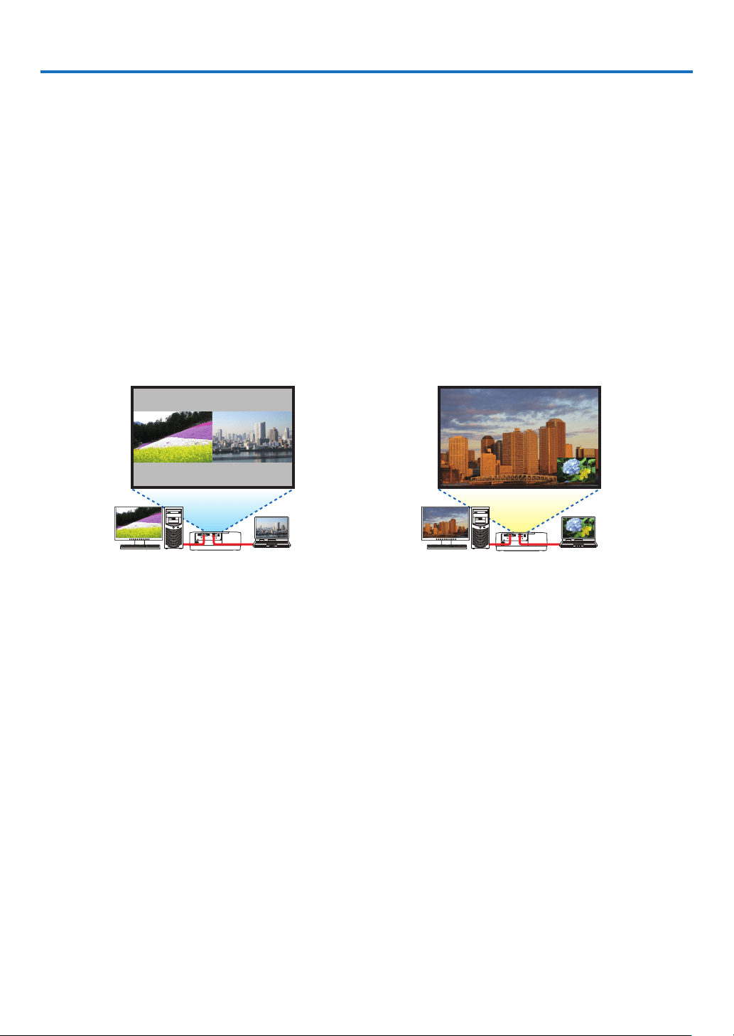
60
4. Multi-Screen Projection
❶ Things that can be done using multi-screen projection
Thisprojectorcanbeusedsinglyorarrangedinmultipleunitsformulti-screenprojection.
Wewillintroduceanexampleusingtwoprojectionscreenshere.
Case 1
Usingasingleprojectortoprojecttwotypesofvideosatthesametime
[PIP/PICTUREBYPICTURE]
Case 2
Usingfourprojectorstoprojectvideowitharesolutionof3840×2160pixels
[TILING]
Case 1. Using a single projector to project two types of videos [PIP/PICTURE BY
PICTURE]
Connectionexampleandprojectionimage
In the case of [PICTURE BY PICTURE] In the case of [PIP]
On-screen menu operations
Display[DISPLAY]→[PIP/PICTUREBYPICTURE]→[MODE]screenintheon-screenmenuandselect[PIP]or
[PICTUREBYPICTURE].
Fordetails,pleasereferto“4-2DisplayingTwoPicturesattheSameTime”.(→page
64)
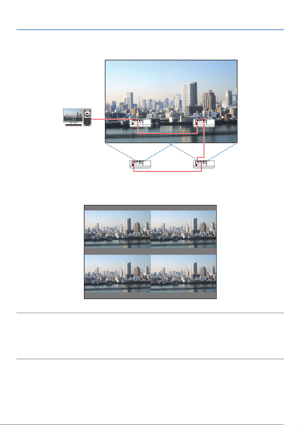
61
4. Multi-Screen Projection
Case 2. Using four projectors to project videos with a resolution of 3840 × 2160 pixels
[TILING]
Connectionexampleandprojectionimage
On-screen menu operations
1Foursimilarvideosaredisplayedwhenfourprojectorsareprojected.
Please request the retail store to adjust the projection position of each projector.
NOTE:
•Whensettinguptheprojector,assignauniquecontrolIDtoeachprojector.
•Setthe“Colorsetting”and“DeepColorsetting”onyourBlu-rayplayerorcomputerto“Auto”.Refertotheowner’smanualac-
companiedwithyourBlu-rayplayerorcomputerformoreinformation.
•ConnectanHDMIoutputofyourBlu-rayplayerorcomputertotherstprojectorandthenconnecttoHDBaseTIN/Ethernetport
ofthesecondandsubsequentprojectors.
•SelectinganotherinputsourceonthesecondandsubsequentprojectorswilldisabletheHDBaseTrepeaterfunction.
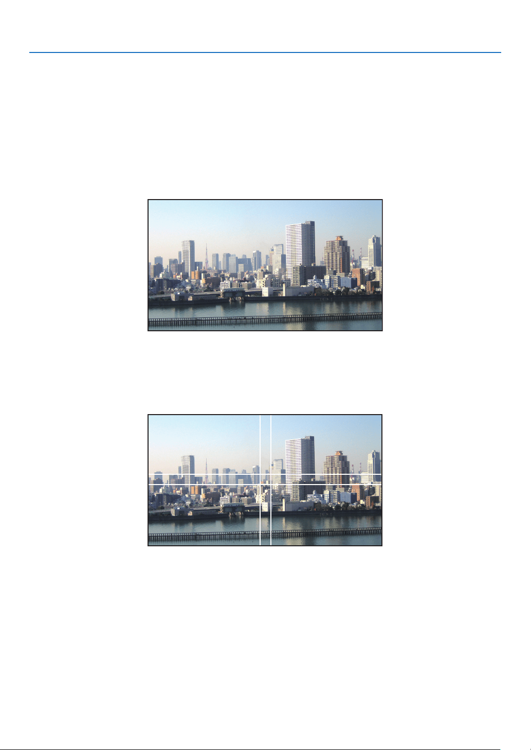
62
4. Multi-Screen Projection
2Operatetheon-screenmenuusingthefourrespectiveprojectorstodividetheimageintofourportions.
Display [DISPLAY] → [MULTI SCREEN] → [PICTURE SETTING] Screen in the on-screen menu and select [TIL-
ING].
(1) In the screen for setting the number of horizontal units, select [2 UNITS]. (number of units in the horizontal
direction)
(2) In the screen for setting the number of vertical units, select [2 UNITS]. (number of units in the vertical direction)
(3) In the screen for setting the horizontal order, select [1st UNIT] or [2nd UNIT].
(look at the screens, the one on the left is the [1st UNIT] while the one on the right is the [2nd UNIT])
(4) In the screen for setting the vertical order, select the [1st UNIT] or the [2nd UNIT].
(look at the screens, the one at the top is the [1st UNIT] while the one at the bottom is the [2nd UNIT])
3Adjustthelensshiftofeachprojectortofine-tunetheboundariesofthescreen.
For further fine-tuning, adjust using [DISPLAY] → [EDGE BLENDING] in the on-screen menu for each projector.
For details, please refer to “4-3 Displaying a Picture Using [EDGE BLENDING]”.
(→ page
68)
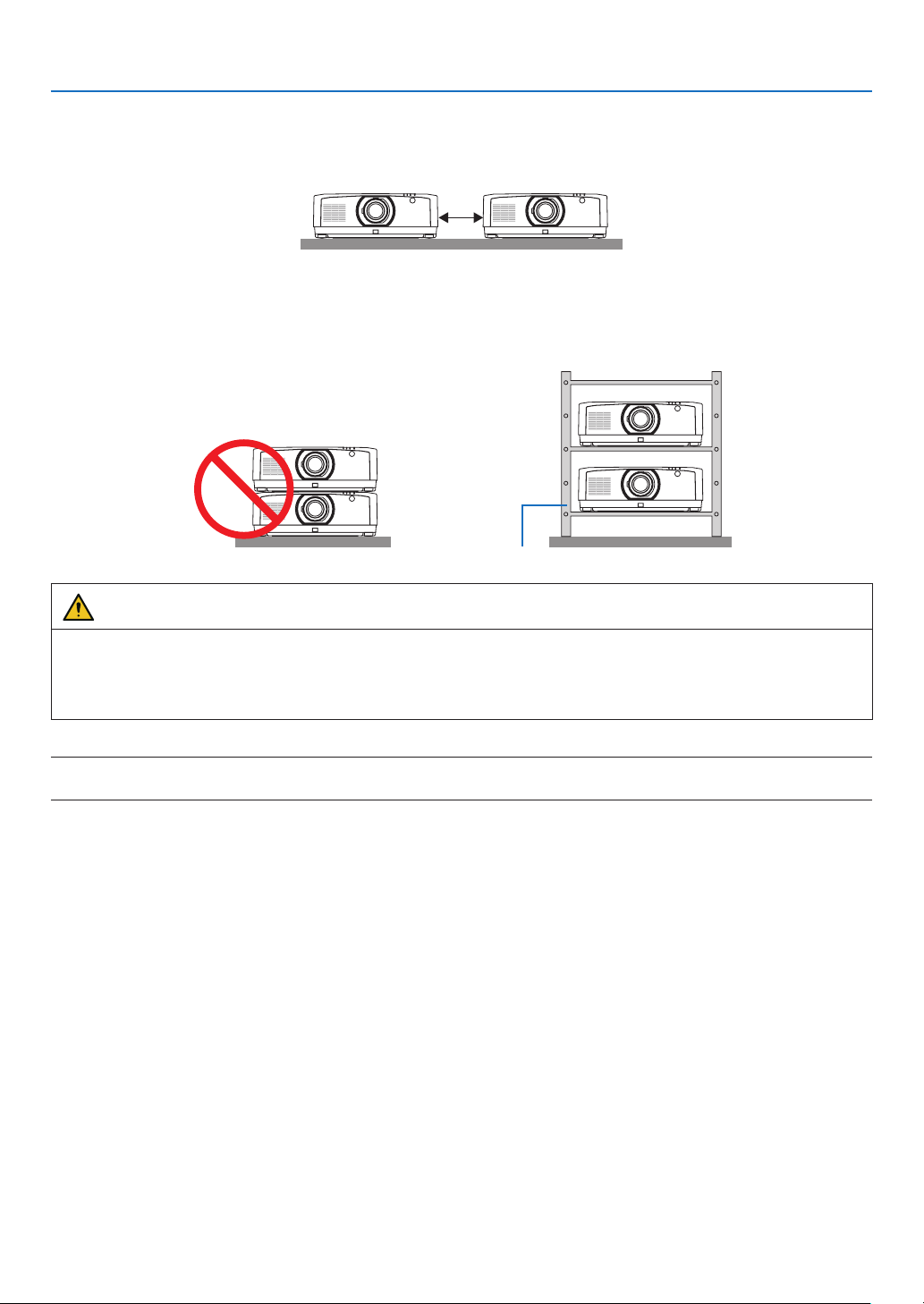
63
4. Multi-Screen Projection
Things to note when installing projectors
•Leavesufficientspaceontheleftandrightoftheprojectorsothattheintakeandexhaustventsoftheprojectorare
notobstructed.Whentheintakeandexhaustventsareobstructed,thetemperatureinsidetheprojectorwillrise
and this may result in a malfunction.
•Pleasedonotpileuptheprojectorsdirectlyontopofoneanotherwheninstallingthem.Whentheprojectorsare
piledupontopofoneanother,theymayfalldown,resultingindamageandfailure.
Thefollowinginstallationisrecommendedwhencombiningtheinstallationoftwoprojectorsformulti-screenprojec-
tion.Pleaseleavesufficientspaceontheleftandrightoftheprojector.
Cabinet
WARNING
Pleaserequesttheretailstoreforspecialinstallationservicessuchaswhenmountingtheprojectortotheceiling.
Nevercarryouttheinstallationbyyourself.Theprojectormayfalldownandresultininjury.Pleaseuseasturdy
cabinetthatcanwithstandtheweightoftheprojectorfortheinstallation.Pleasedonotpileuptheprojectorsdirectly
on top of one another.
NOTE:
•Fortherangeoftheprojectiondistance,pleaserefertotheAppendix“Throwdistanceandscreensize”.(→page
152)
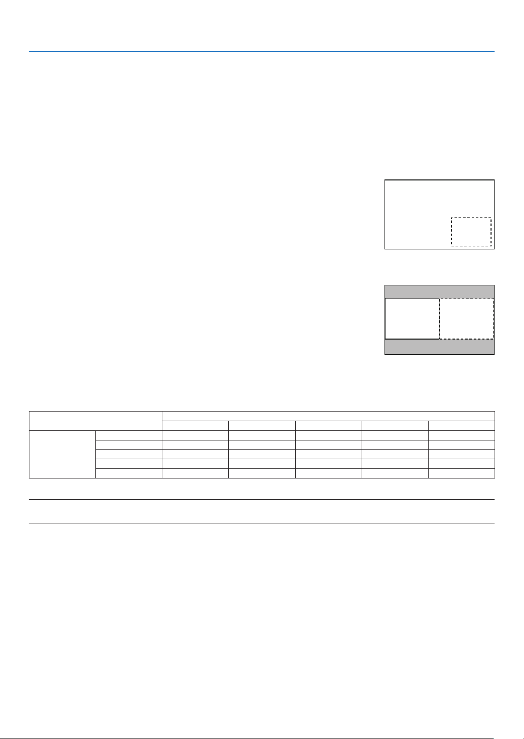
64
4. Multi-Screen Projection
❷ Displaying Two Pictures at the Same Time
Theprojectorhasafeaturethatallowsyoutoviewtwodifferentsignalssimultaneously.Youhavetwomodes:PIP
modeandPICTUREBYPICTUREmode.
Theprojectionvideointherstscreendisplayisknownasthemaindisplaywhiletheprojectionvideothatiscalled
outsubsequentlyisknownasthesub-display.
Selecttheprojectionfunctionunder[DISPLAY]→[PIP/PICTUREBYPICTURE]→[MODE]intheon-screenmenu
(thedefaultfactorysettingwhenshippedisPIP).(→page
99)
•Asinglescreenisprojectedwhenpoweristurnedon.
PictureinPicturefunction
A small sub-display is displayed inside the main display.
Thesub-displaycanbesetupandadjustedasfollows.(→page
99)
•Selectwhethertodisplaythesub-displayatthetopright,topleft,bottomright
orbottomleftofthescreen(thesizeofthesub-displaycanbeselectedand
thepositioncanbene-tuned)
•Switchthemaindisplaywiththesub-display
Main Display
Sub-Display
Picturebypicturefunction
Displaythemaindisplayandsub-displaysidebyside.
Themaindisplayandsub-displaycanbesetupandadjustedasfollows.(→
page100)
•Selectingthedisplayboundary(ratio)ofthemaindisplayandsub-display
•Switchthemaindisplayandsub-display
Main Display Sub-Display
Inputterminalsthatcanbeusedforthemainscreenandsub-screen.
Themainscreenandsub-screencanprovidethefollowinginputterminals.
•Themaindisplayandsub-displaysupportcomputersignalsuptoWUXGA@60HzRB.
Sub-Display or additional display
HDMI1 HDMI2 DisplayPort COMPUTER HDBaseT
Main Display
HDMI1 No Yes Yes Yes Yes
HDMI2 Yes No Yes Yes Yes
DisplayPort Yes Yes No Yes Yes
COMPUTER Yes Yes Yes No Yes
HDBaseT Yes Yes Yes Yes No
NOTE:
•Somesignalsmaynotappeardependingontheresolution.
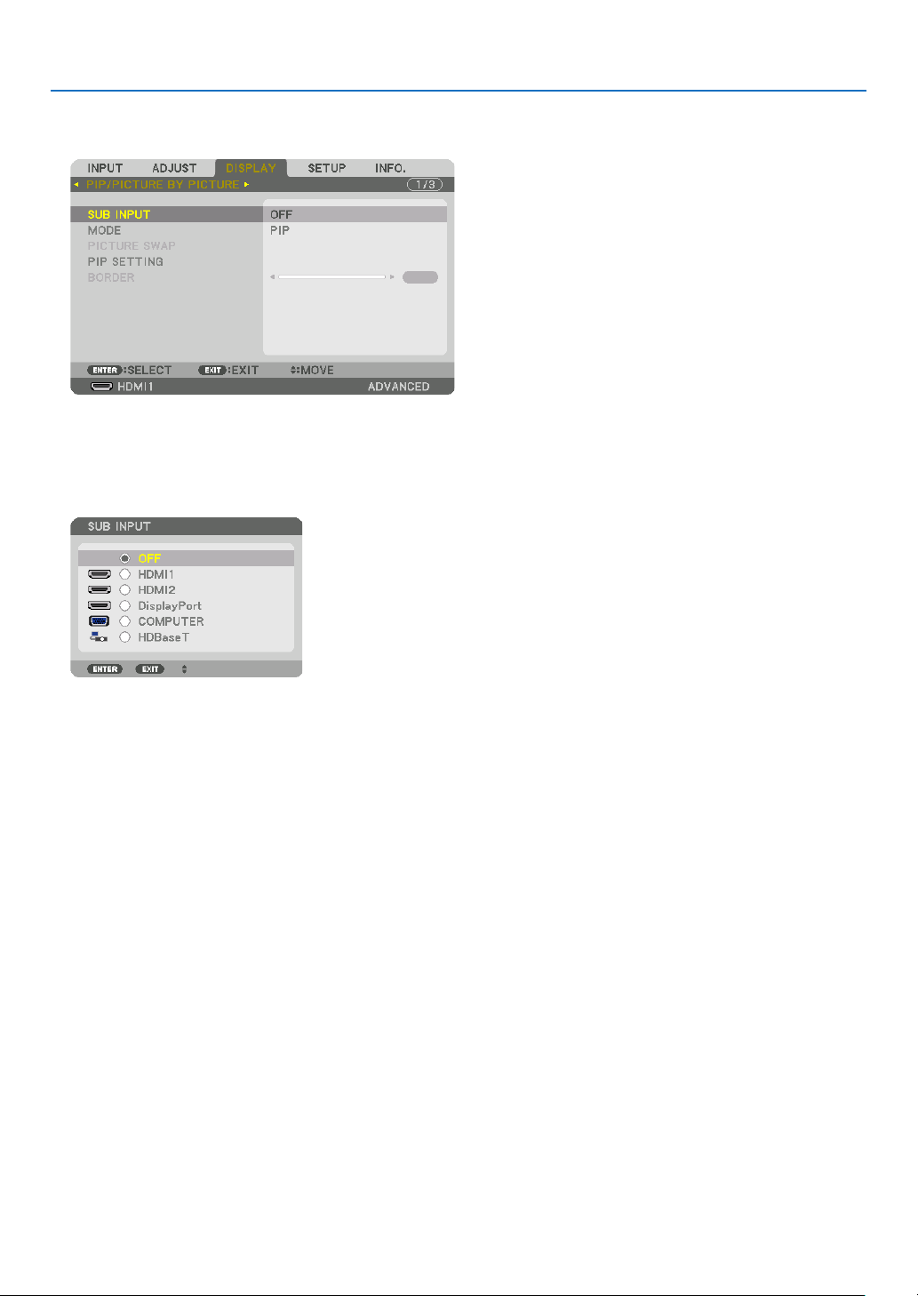
65
4. Multi-Screen Projection
Projecting two screens
1.PresstheMENUbuttontodisplaytheon-screenmenuandselect[DISPLAY]→[PIP/PICTUREBYPICTURE].
This displays the [PIP/PICTURE BY PICTURE] screen in the on-screen menu.
2.Select[SUBINPUT]usingthe▼/▲buttons,andpresstheENTERbutton.
This displays the [SUB INPUT] screen.
3.Selecttheinputsignalusingthe▼/▲buttons,andpresstheENTERbutton.
* This screen belongs to a HDBaseT model.
The [PIP] (PICTURE IN PICTURE) or [PICTURE BY PICTURE] screen set up under [MODE] is projected. (→
page
99)
•Whenthesignalnameisdisplayedingrey,thismeansthatitcannotbeselected.
•ThesignalcanalsobeselectedbypressingthePIPbuttonorPBP/POPbuttonontheremotecontrol.
4.PresstheMENUbutton.
The on-screen menu will disappear.
5.Whenreturningtosinglescreen,displaythe[PIP/PICTUREBYPICTUE]screenonemoretimeandselect
[OFF]inthe[SUBINPUT]screenoftheStep3.
TIP:
•Duringdual-screenprojection,iftheselectedinputisnotsupportedbythesub-screen,thesub-screenwillappearasablack
screen.
66
4. Multi-Screen Projection
Switching the main display with the sub-display and vice versa
1.PresstheMENUbuttontodisplaytheon-screenmenuandselect[DISPLAY]→[PIP/PICTUREBYPICTURE].
This displays the [PIP/PICTURE BY PICTURE] screen in the on-screen menu.
2.Select[PICTURESWAP]usingthe▼/▲buttonsandthenpresstheENTERbutton.
Display the screen for switching the display positions.
3.Select[ON]usingthe▼buttonandthenpresstheENTERbutton.
The video of the main display will switch with that of the sub-display.
When turned “OFF” When turned “ON”
Sub-display video
Main display video Sub-display video
Main display video
The signal output from the HDBaseT OUT/Ethernet terminal does not change even if the display positions are
switched.
4.PresstheMENUbutton.
The on-screen menu will disappear.

67
4. Multi-Screen Projection
Restrictions
•Thefollowingoperationsareenabledonlyforthemaindisplay.
•Audio-visualadjustments
•Videomagnication/compressionusingthepartialD-ZOOM/ZOOM+/−buttons.
However,magnication/compressionisuptothepositionssetin[PICTUREBYPICTUREBORDER]only.
•TESTPATTERN
•Thefollowingoperationsareenabledforboththemaindisplayandsub-display.Theseoperationscannotbeap-
plied individually.
•Momentarydeletionofvideo/audio
•Videopause
•[PIP/PICTUREBYPICTURE]cannotbeusedwhena3Dvideoisbeingdisplayed.
•Whenusingthe[PIP/PICTUREBYPICTURE]function,[DYNAMICCONTRAST]cannotbeused.
•[PIP/PICTUREBYPICTURE]cannotbeusedwhenthesignalinputhasaresolutionof1920×1200ormore.
•TheHDBaseTOUT/Ethernetporthasarepeaterfunction.Theoutputresolutionislimitedbythemaximumresolu-
tion of the connected monitor and projector.
68
4. Multi-Screen Projection
❸ Displaying a Picture Using [EDGE BLENDING]
Ahighresolutionvideocanbeprojectedonanevenbiggerscreenbycombiningmultipleprojectorsontheleft,right,
top and bottom.
Thisprojectorisequippedwithan“EDGEBLENDINGFunction”thatmakestheedges(boundaries)oftheprojection
screenindistinguishable.
NOTE:
•Forprojectorthrowdistances,referto“Throwdistanceandscreensize”onpage
152.
•BeforeperformingtheEdgeBlendingfunction,placetheprojectorinthecorrectpositionsothattheimagebecomessquarein
theappropriatesize,andthenmakeopticaladjustments(lensshift,focus,andzoom).
•Adjustthebrightnessofeachprojectorusing[REF.LIGHTADJUST]under[LIGHTMODE].Inaddition,use[REF.WHITEBALANCE]
toadjustthe[CONTRAST],[BRIGHTNESS]and[UNIFORMITY].
BeforeexplaininguseoftheEdgeBlendingfunction
Thissectionexplainsthecasefor“Example:Placingtwoprojectorssidebyside”.Asshown,theprojectedimageon
theleftisreferredtoas“ProjectorA”andtheprojectedimageontherightisreferredto“ProjectorB”.Unlessotherwise
speciedhereinafter,the“projector”isusedtomeanbothAandB.
Example:Placingtwoprojectorssidebyside
Edge Blending area
Projected area
Projected area
Projector A Projector B
69
4. Multi-Screen Projection
Preparation:
•Turnontheprojectoranddisplayasignal.
•Whenperformingsettingsoradjustmentsusingoneremotecontrol,enablethe[CONTROLID]forassigningIDto
each projector so as not to activate the other projectors. (→page
121)
Setting the overlap of projection screens
①
Enable[EDGEBLENDING].
1Pressthe“EdgeBlend.”button.
The [EDGE BLENDING] screen will be displayed. Align the cursor with [MODE] and then press the ENTER but-
ton. The mode screen will be displayed.
2Select[MODE]→[ON]andpresstheENTERbutton.
This enables the Edge Blending function. The following menu items are available:
[TOP], [BOTTOM], [LEFT], [RIGHT], [BLACK LEVEL], and [BLEND CURVE]
3Select[RIGHT]forProjectorAand[LEFT]forProjectorB.
Press the ENTER button.
The following items are available:
[CONTROL], [MARKER], [RANGE], and [POSITION]
70
4. Multi-Screen Projection
4Select[CONTROL]→[ON]andpresstheENTERbutton.
Each [TOP], [BOTTOM], [LEFT], [RIGHT], and [BLACK LEVEL] has its own [CONTROL], [MARKER], [RANGE],
and [POSITION].
•ForProjectorA,setthe[CONTROL]forthe[TOP],[LEFT]and[BOTTOM]to[OFF].SimilarlyforProjectorB,
set the [CONTROL] for the [TOP], [RIGHT] and [BOTTOM] to [OFF].
②Adjust[RANGE]and[POSITION]todetermineanareaofoverlappededgesofimages
projectedfromeachprojector.
Turningon[MARKER]willdisplaymarkersinmagentaandgreen.
Themagentamarkerisusedfor[RANGE]andgreenonefor[POSITION].
[RANGE]
(Determine an area of overlapped edges of
images.)
[POSITION]
(Determine the position of overlapped edges of images.)
Green marker
Turn on [RIGHT]
Magenta marker
Turn on [LEFT]
Magenta marker
*The2screensareseparatedinthediagramforexplanatorypurposes.
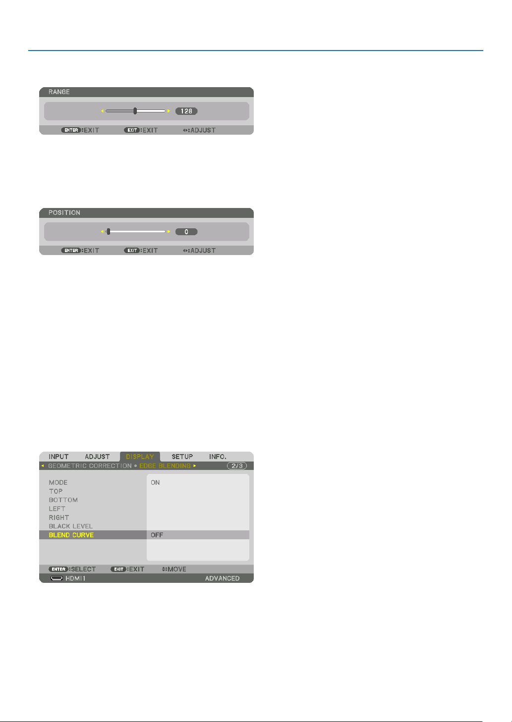
71
4. Multi-Screen Projection
1Adjust[RANGE].
Use the ◀ or ▶ button to adjust the overlapped area.
TIP:
•Adjusttooverlaponeprojector’markerwiththeotherprojector’smarker.
2Adjust[POSITION].
Use the ◀ or ▶ button to align one edge with the other edge of overlapped images.
TIP:
•Whendisplayingasignalwithadifferentresolution,performtheEdgeBlendingfunctionfromthestart.
•Settingof[MARKER]willnotbesavedandreturnto[OFF]whentheprojectoristurnedoff.
•Todisplayorhidethemarkerwhiletheprojectorisrunning,turnonoroff[MARKER]fromthemenu.
[BLEND CURVE]
Adjustthebrightnessoftheoverlappedsectiononthescreens.Accordingtothenecessity,adjustthebrightnessof
theoverlappedsectiononthescreensbythe[BLENDCURVE]AND[BLACKLEVEL].
•Setthe[MODE]to[ON]forselecting[BLENDCURVE]and[BLACKLEVEL].
Selectinganoptionforthe[BLENDCURVE]
Bycontrollingthegraduationoftheoverlappedsectiononthescreens,itmakestheborderontheprojectedscreens
inconspicuous.Selecttheoptimaloptionamongnine.
1.OntheOn-ScreenMenu,movethecursorontothe[DISPLAY]→[EDGEBLENDING]→[BLENDCURVE]and
thenpresstheENTER.Theoptionsettingscreenforthe[BRENDCURVE]isdisplayedon.
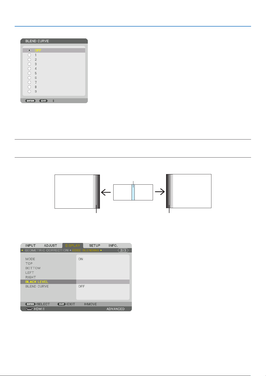
72
4. Multi-Screen Projection
2.Selectoneoptionamongnineby▲ or ▼.
Black Level Adjustment
Thisadjuststheblackleveloftheoverlappingareaandthenon-overlappingareaofthemulti-screen(EDGEBLENDING).
Adjustthebrightnesslevelifyoufeelthedifferenceistoolarge.
NOTE:
Thisfunctionisenabledonlywhen[MODE]isturnedon.
Adjustableareavariesdependingonwhatcombinationof[TOP],[BOTTOM],[LEFT]and[RIGHT]areturnedon.
Example:AdjustingtheBlackLevelwhenplacingtwoprojectorssidebyside
Width of overlap
Adjust [CENTER] Adjust [CENTER]
Projector A’s
image
Projector B’s
image
Adjust [CENTER-RIGHT] Adjust [CENTER-LEFT]
1.Select[DISPLAY]→[EDGEBLENDING]→[BLACKLEVEL]andpresstheENTERbutton.
The screen will switch to the black level adjustment screen.
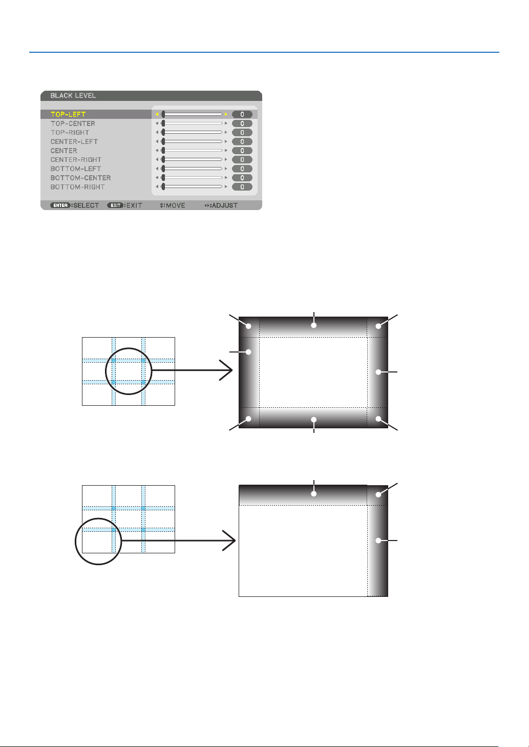
73
4. Multi-Screen Projection
2.Usethe▼ or ▲buttontoselectanitemandusethe◀ or ▶toadjusttheblacklevel.
Do this for the other projector if necessary.
9-segmentedportionsforBlackLeveladjustment
Thecenterprojector
Thisfunctionadjuststhebrightnesslevelof9-segmentedportionsforthecenterprojectorand4-segmentedportions
for the left bottom projector as shown below.
TOP-LEFT
BOTTOM-LEFT
CENTER-
LEFT
TOP-RIGHT
CENTER-RIGHT
BOTTOM-RIGHT
TOP-CENTER
CENTER
CENTER
BOTTOM-CENTER
TOP-RIGHT
CENTER-RIGHT
TOP-CENTER
TIP:
•Thenumberofblackleveldivisionscreens(maximumofninedivisions)changesdependingonthenumberofedgeblending
positionsselected(top,bottom,right,left).Inaddition,whenthetop/bottomandleft/rightendsareselected,thecornerdivision
screenappears.
•Theedgeblendingwidthisthewidthsetintherangeandthecornerisformedbytheintersectingareaofthetop/bottomends
orleft/rightends.
•The[BLACKLEVEL]canbeadjustedtomakeitbrighteronly.
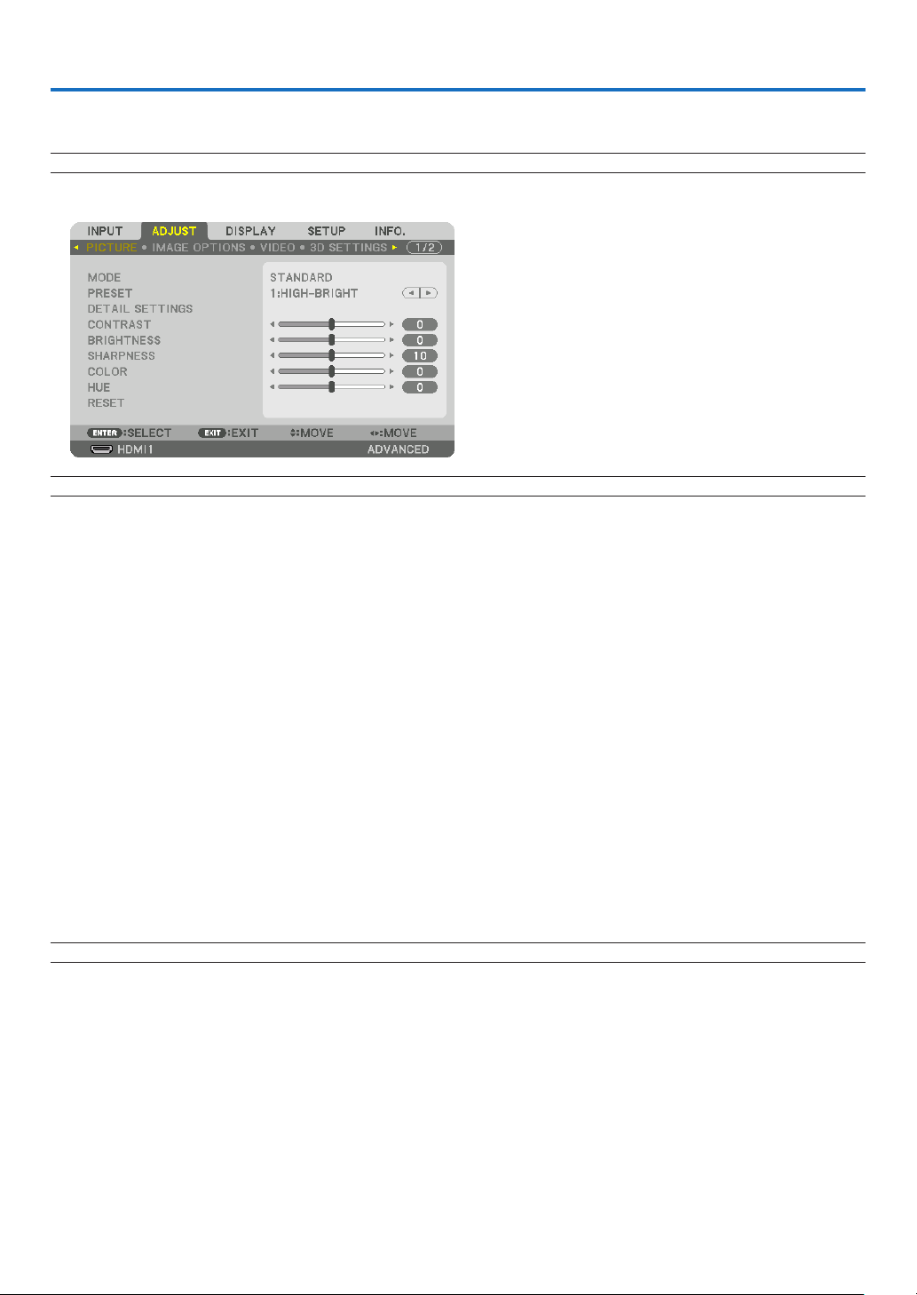
74
5. Using On-Screen Menu
❶ Using the Menus
NOTE:Theon-screenmenumaynotbedisplayedcorrectlywhileinterlacedmotionvideoimageisprojected.
1.PresstheMENUbuttonontheremotecontrolortheprojectorcabinettodisplaythemenu.
NOTE:ThecommandssuchasENTER,EXIT,▲▼,◀▶inthebottomshowavailablebuttonsforyouroperation.
2.Pressthe◀▶buttonsontheremotecontrolortheprojectorcabinettodisplaythesubmenu.
3.PresstheENTERbuttonontheremotecontrolortheprojectorcabinettohighlightthetopitemorthefirst
tab.
4.Usethe▲▼buttonsontheremotecontrolortheprojectorcabinettoselecttheitemyouwanttoadjustor
set.
Youcanusethe◀▶buttonsontheremotecontrolortheprojectorcabinettoselectthetabyouwant.
5.PresstheENTERbuttonontheremotecontrolortheprojectorcabinettodisplaythesubmenuwindow.
6.Adjustthelevelorturntheselecteditemonoroffbyusingthe▲▼◀▶buttonsontheremotecontrolorthe
projectorcabinet.
Changes are stored until adjusted again.
7.Repeatsteps2-6toadjustanadditionalitem,orpresstheEXITbuttonontheremotecontrolortheprojector
cabinettoquitthemenudisplay.
NOTE:Whenamenuormessageisdisplayed,severallinesofinformationmaybelost,dependingonthesignalorsettings.
8.PresstheMENUbuttontoclosethemenu.
Toreturntothepreviousmenu,presstheEXITbutton.
75
5. Using On-Screen Menu
❷
Menu Elements
Slide bar
Solid triangle
Menu mode
Ta b
Radio button
High Altitude symbol
LIGHT MODE symbol
Menuwindowsordialogboxestypicallyhavethefollowingelements:
Highlight ............................. Indicates the selected menu or item.
Solid triangle ......................Indicates further choices are available. A highlighted triangle indicates the item is active.
Tab ......................................Indicates a group of features in a dialog box. Selecting on any tab brings its page to the front.
Radio button ....................... Use this round button to select an option in a dialog box.
Source ................................Indicates the currently selected source.
Menu mode ........................Indicates the current menu mode: BASIC or ADVANCED.
Off Timer remaining time .... Indicates the remaining countdown time when the [OFF TIMER] is preset.
Slide bar .............................Indicates settings or the direction of adjustment.
LIGHT MODE symbol ..........Indicates [LIGHT MODE] is set.
Key Lock symbol ................Indicates the [CONTROL PANEL LOCK] is enabled.
Thermometer symbol .........Indicates the [LIGHT MODE] is forcibly set to [ON] mode because the internal temperature is too
high.
High Altitude symbol ..........Indicates the [FAN MODE] is set to [HIGH ALTITUDE] mode.
Source
Available buttons
Thermometer symbol
Key Lock symbol
Off Timer remaining
time
Highlight
76
5. Using On-Screen Menu
*Theasterisk(*)indicatesthatthedefaultsettingvariesdependingonthesignal.
*1The[GAMMACORRECTION]itemisavailablewhenanitemotherthan[DICOMSIM.]isselectedfor[REFERENCE].
*2The[SCREENSIZE]itemisavailablewhen[DICOMSIM.]isselectedfor[REFERENCE].
*3When[HIGH-BRIGHT]isselectedin[REFERENCE],the[COLORTEMPERATURE]isnotavailable.
*4The[INPUTRESOLUTION]itemcanbeselectedforCOMPUTERinput.
*5The[HDRMODE]itemisavailableexclusivelyfor4Ksignal.
•Basicmenuitemsareindicatedbyshadedarea.
❸ List of Menu Items
Somemenuitemsarenotavailabledependingontheinputsource.
Menu Item Default Options
INPUT
1:HDMI1 *
2:HDMI2 *
3:DisplayPort *
4:COMPUTER *
5:HDBaseT
ENTRY LIST
TEST PATTERN
ADJUST
PICTURE
MODE STANDARD STANDARD, PROFESSIONAL
PRESET *
AUTO, 1:HIGH-BRIGHT, 2:PRESENTATION, 3:VIDEO, 4:MOVIE,
5:GRAPHIC, 6:sRGB, 7:DICOM SIM.
DETAIL SETTINGS
GENERAL
REFERENCE *
HIGH-BRIGHT, PRESENTATION, VIDEO, MOVIE, GRAPHIC, sRGB,
DICOM SIM.
GAMMA CORRECTION*
1
DYNAMIC, NATURAL, BLACK DETAIL
SCREEN SIZE*
2
* LARGE, MEDIUM, SMALL
COLOR TEMPERATURE*
3
*
DYNAMIC CONTRAST * OFF, MOTION IMAGE, STILL IMAGE
LIGHT ADJUST *
WHITE BALANCE
CONTRAST R 0
CONTRAST G 0
CONTRAST B 0
BRIGHTNESS R 0
BRIGHTNESS G 0
BRIGHTNESS B 0
COLOR CORRECTION
RED 0 HUE, SATURATION
GREEN 0 HUE, SATURATION
BLUE 0 HUE, SATURATION
YELLOW 0 HUE, SATURATION
MAGENTA 0 HUE, SATURATION
CYAN 0 HUE, SATURATION
CONTRAST 50
BRIGHTNESS 50
SHARPNESS 10
COLOR 50
HUE 0
VOLUME
RESET
IMAGE
OPTIONS
CLOCK *
PHASE *
HORIZONTAL *
VERTICAL *
BLANKING * TOP, BOTTOM, LEFT, RIGHT
OVERSCAN AUTO, 0[%], 5[%], 10[%]
ASPECT RATIO
AUTO
(HDTV/SDTV) AUTO, NORMAL, 4:3, LETTERBOX, WIDE SCREEN,
ZOOM, FULL
AUTO
(COMPUTER) AUTO, NORMAL, 4:3, 5:4, 16:9, 15:9, 16:10, FULL,
NATIVE
INPUT RESOLUTION*
4
* –
VIDEO
NOISE REDUCTION
RANDOM NR * OFF, LOW, MEDIUM, HIGH
MOSQUITO NR OFF OFF, LOW, MEDIUM, HIGH
BLOCK NR OFF OFF, LOW, MEDIUM, HIGH
DEINTERLACE NORMAL NORMAL, MOVIE, STILL
CONTRAST
ENHANCEMENT
MODE AUTO OFF, AUTO, NORMAL
GAIN
SIGNAL TYPE AUTO AUTO, RGB, REC601, REC709, REC2020
VIDEO LEVEL AUTO AUTO, NORMAL, ENHANCED, SUPER WHITE
HDR MODE*
5
AUTO AUTO, OFF, ON

77
5. Using On-Screen Menu
Menu Item Default Options
ADJUST
3D SETTINGS
STEREO VIEWER SINGLE SINGLE, DUAL LEFT, DUAL RIGHT
STEREO FILTER SINGLE SINGLE, DUAL LEFT, DUAL RIGHT
FORMAT AUTO
AUTO, OFF(2D), FRAME PACKING, SIDE BY SIDE(HALF), SIDE
BY SIDE(FULL), TOP AND BOTTOM, FRAME ALTERNATIVE, LINE
ALTERNATIVE
L/R INVERT OFF OFF, ON
LENS
MEMORY
STORE
MOVE
RESET
DISPLAY
PIP/PICTURE
BY PICTURE
SUB INPUT OFF OFF, HDMI1, HDMI2, DisplayPort, COMPUTER, HDBaseT
MODE PIP PIP, PICTURE BY PICTURE
PICTURE SWAP OFF OFF, ON
PIP SETTING
START POSITION TOP-LEFT TOP-LEFT, TOP-RIGHT, BOTTOM-LEFT, BOTTOM-RIGHT
HORIZONTAL POSITION
VERTICAL POSITION
SIZE MEDIUM LARGE, MEDIUM, SMALL
BORDER
GEOMETRIC
CORRECTION
MODE OFF
OFF, KEYSTONE, CORNERSTONE, HORIZONTAL CORNER,
VERTICAL CORNER, WARP, PC TOOL
KEYSTONE
HORIZONTAL
VERTICAL
TILT
THROW RATIO
CORNERSTONE
TOP-LEFT, TOP, TOP-RIGHT, LEFT, RIGHT, BOTTOM-LEFT,
BOTTOM, BOTTOM-RIGHT
HORIZONTAL CORNER
TOP-LEFT, TOP, TOP-RIGHT, LEFT, RIGHT, BOTTOM-LEFT,
BOTTOM, BOTTOM-RIGHT
VERTICAL CORNER
TOP-LEFT, TOP, TOP-RIGHT, LEFT, RIGHT, BOTTOM-LEFT,
BOTTOM, BOTTOM-RIGHT
WARP
TOP-LEFT, TOP, TOP-RIGHT, LEFT, RIGHT, BOTTOM-LEFT,
BOTTOM, BOTTOM-RIGHT
PC TOOL OFF OFF, 1, 2, 3
RESET
EDGE
BLENDING
MODE OFF OFF, ON
TOP
CONTROL ON OFF, ON
MARKER OFF OFF, ON
RANGE
POSITION
BOTTOM
CONTROL ON OFF, ON
MARKER OFF OFF, ON
RANGE
POSITION
LEFT
CONTROL ON OFF, ON
MARKER OFF OFF, ON
RANGE
POSITION
RIGHT
CONTROL ON OFF, ON
MARKER OFF OFF, ON
RANGE
POSITION
BLACK LEVEL
TOP-LEFT
TOP-CENTER
TOP-RIGHT
CENTER-LEFT
CENTER
CENTER-RIGHT
BOTTOM-LEFT
BOTTOM-CENTER
BOTTOM-RIGHT
BLEND CURVE 5 OFF, 1, 2, 3, 4, 5, 6, 7, 8, 9
78
5. Using On-Screen Menu
Menu Item Default Options
DISPLAY
MULTI
SCREEN
WHITE BALANCE
MODE OFF OFF, ON
CONTRAST W
CONTRAST R
CONTRAST G
CONTRAST B
BRIGHTNESS W
BRIGHTNESS R
BRIGHTNESS G
BRIGHTNESS B
PICTURE SETTING
MODE OFF OFF, ZOOM, TILING
ZOOM
HORIZONTAL ZOOM
VERTICAL ZOOM
HORIZONTAL
POSITION
VERTICAL POSITION
TILING
WIDTH 1 UNIT, 2 UNITS, 3 UNITS, 4 UNITS
HEIGHT 1 UNIT, 2 UNITS, 3 UNITS, 4 UNITS
HORIZONTAL
POSITION
1st UNIT, 2nd UNIT, 3rd UNIT, 4th UNIT
VERTICAL POSITION 1st UNIT, 2nd UNIT, 3rd UNIT, 4th UNIT
SETUP
MENU(1)
LANGUAGE ENGLISH
ENGLISH, DEUTSCH, FRANÇAIS, ITALIANO, ESPAÑOL, SVENSKA,
日本語
DANSK, PORTUGUÊS, ČEŠTINA, MAGYAR, POLSKI,
NEDERLANDS, SUOMI
NORSK, TÜRKÇE, РУССКИЙ,
, Ελληνικά, 简体中文, 한국어
ROMÂNĂ, HRVATSKA, БЪЛГАРСКИ, INDONESIA, , ไทย,
, 繁體中文, Tiếng Việt
COLOR SELECT COLOR COLOR, MONOCHROME
INPUT DISPLAY ON OFF, ON
MESSAGE DISPLAY ON OFF, ON
ID DISPLAY ON OFF, ON
3D CAUTION MESSAGE ON OFF, ON
DISPLAY TIME
AUTO 45
SEC
MANUAL, AUTO 5 SEC, AUTO 15 SEC, AUTO 45 SEC
MENU(2)
MENU ANGLE 0°, 90°, 270°
MENU POSITION
HORIZONTAL POSITION
VERTICAL POSITION
RESET
INSTALLA-
TION(1)
ORIENTATION AUTO
AUTO, DESKTOP FRONT, CEILING REAR, DESKTOP REAR,
CEILING FRONT
SCREEN
SCREEN TYPE FREE FREE, 4:3 SCREEN, 16:9 SCREEN, 16:10 SCREEN
POSITION
WALL COLOR OFF
OFF, WHITEBOARD, BLACKBOARD, BLACKBOARD (GRAY), LIGHT
YELLOW, LIGHT GREEN, LIGHT BLUE, SKY BLUE, LIGHT ROSE,
PINK
FAN MODE AUTO AUTO, NORMAL, HIGH, HIGH ALTITUDE
LIGHT MODE
LIGHT MODE ECO1 NORMAL, ECO1, ECO2, LONG LIFE
CONSTANT BRIGHTNESS OFF OFF, ON
REF. LIGHT ADJUST
REF. WHITE BALANCE
CONTRAST R
CONTRAST G
CONTRAST B
BRIGHTNESS R
BRIGHTNESS G
BRIGHTNESS B
UNIFORMITY R
UNIFORMITY B
STATIC CONVERGENCE
HORIZONTAL R
HORIZONTAL G
HORIZONTAL B
VERTICAL R
VERTICAL G
VERTICAL B
REF. LENS MEMORY
PROFILE 1 1, 2
STORE
MOVE
RESET
LOAD BY SIGNAL OFF OFF, ON
FORCED MUTE OFF OFF, ON
LENS CALIBRATION
79
5. Using On-Screen Menu
Menu Item Default Options
SETUP
INSTALLA-
TION(2)
SHUTTER SETTINGS
POWER ON SHUTTER OPEN OPEN, CLOSE
FADE IN TIME 0–10 SEC
FADE OUT TIME 0–10 SEC
CONTROL
TOOLS
ADMINISTRA-
TOR MODE
MENU MODE ADVANCED ADVANCED, BASIC
NOT SAVE SETTING VALUES OFF OFF, ON
NEW PASSWORD
CONFIRM PASSWORD
PROGRAM
TIMER
ENABLE OFF OFF, ON
SETTINGS
EDIT
ACTIVE OFF OFF, ON
DAY SUN
SUN, MON, TUE, WED, THU, FRI, SAT, MON-FRI, MON-SAT,
EVERY DAY
TIME
FUNCTION POWER POWER, INPUT, LIGHT MODE
ADVANCED
SETTINGS
POWER OFF OFF, ON
INPUT HDMI1 HDMI1, HDMI2, DisplayPort, COMPUTER, HDBaseT
LIGHT MODE ECO1 NORMAL, ECO1, ECO2, LONG LIFE
REPEAT OFF OFF, ON
DELETE
UP
DOWN
BACK
DATE AND TIME
SETTINGS
TIME
ZONE
SETTIMGS
UTC
-12:00, -11:30, -11:00, -10:30, -10:00, -09:30, -09:00, -08:30,
-08:00, -07:30, -07:00, -06:30, -06:00, -05:30, -05:00, -04:30,
-04:00, -03:30, -03:00, -02:30, -02:00, -01:30, -01:00, -00:30,
00:00, +00:30, +01:00, +01:30, +02:00, +02:30, +03:00, +03:30,
+04:00, +04;30, +05:00, +05:30, +06:00, +06:30, +07:00, +07:30,
+08:00, +08:30, +09:00, +09:30, +10:00, +10:30, +11:00, +11:30,
+12:00, +12:30, +13:00
DATE
AND TIME
SETTINGS
DATE MM/DD/YYYY
TIME HH:MM
INTERNET TIME
SERVER
OFF, ON
IP ADDRESS
UPDATE
SUMMER
TIME
SETTINGS
ENABLE OFF, ON
MON(START) 1, 2, 3, 4, 5, 6, 7, 8, 9, 10, 11, 12
DAY(START)
FIRST WEEK, SECOND WEEK, THIRD WEEK, FOURTH WEEK, LAST
WEEK
SUN, MON, TUE, WED, THU, FRI, SAT
TIME(START)
MON(EXIT) 1, 2, 3, 4, 5, 6, 7, 8, 9, 10, 11, 12
DAY(EXIT)
FIRST WEEK, SECOND WEEK, THIRD WEEK, FOURTH WEEK, LAST
WEEK
SUN, MON, TUE, WED, THU, FRI, SAT
TIME(EXIT)
TIME DIFFERENCE +01:00, +00:30, -00:30, -01:00
MOUSE
BUTTON RIGHT HAND RIGHT HAND, LEFT HAND
SENSITIVITY MEDIUM FAST, MEDIUM, SLOW
CONTROL PANEL LOCK OFF OFF, ON
SECURITY OFF OFF, ON
COMMUNICATION SPEED 38400bps 4800bps, 9600bps, 19200bps, 38400bps, 115200bps
CONTROL ID
CONTROL ID NUMBER 1 1–254
CONTROL ID OFF OFF, ON, AUTO
REMOTE SENSOR
FRONT/
BACK
FRONT/BACK, FRONT, BACK, HDBaseT
80
5. Using On-Screen Menu
Menu Item Default Options
SETUP
NETWORK
SETTINGS
WIRED LAN
INTERFACE LAN, HDBaseT
PROFILES DISABLE, PROFILE 1, PROFILE 2
DHCP OFF, ON
IP ADDRESS
SUBNET MASK
GATEWAY
AUTO DNS OFF, ON
DNS CONFIGURATION
RECONNECT
PROJECTOR NAME PROJECTOR NAME PJ-********
DOMAIN
HOST NAME pj-********
DOMAIN NAME
ALERT MAIL
ALERT MAIL OFF, ON
HOST NAME pj-********
DOMAIN NAME
SENDER'S ADDRESS
SMTP SERVER NAME
RECIPIENT'S ADDRESS 1
RECIPIENT'S ADDRESS 2
RECIPIENT'S ADDRESS 3
TEST MAIL
NETWORK SERVICE
HTTP
SERVER
NEW PASSWORD
CONFIRM PASSWORD
PJLink
NEW PASSWORD
CONFIRM PASSWORD
AMX BEACON OFF, ON
CREST-
RON
ROOMVIEW
CRESTRON
CONTROL
ENABLE
IP
ADDRESS
IP ID
Extron XTP OFF, ON
SOURCE
OPTIONS
AUTO ADJUST NORMAL OFF, NORMAL, FINE
AUDIO SELECT
HDMI1 HDMI1 HDMI1, COMPUTER
HDMI2 HDMI2 HDMI2, COMPUTER
DisplayPort DisplayPort DisplayPort, COMPUTER
HDBaseT HDBaseT HDBaseT, COMPUTER
DEFAULT INPUT SELECT LAST LAST, AUTO, HDMI1, HDMI2, DisplayPort, COMPUTER, HDBaseT
SEAMLESS SWITCHING OFF OFF, ON
BACKGROUND BLUE BLUE, BLACK, LOGO
HDBaseT OUT SELECT AUTO AUTO, HDMI1, HDMI2, DisplayPort, HDBaseT
EDID VERSION
HDMI1 MODE1 MODE1, MODE2
HDMI2 MODE1 MODE1, MODE2
HDCP VERSION
HDMI1
HDCP2.2 HDCP2.2, HDCP1.4
HDMI2 HDCP2.2 HDCP2.2, HDCP1.4
HDBaseT HDCP1.4 HDCP2.2, HDCP1.4
POWER
OPTIONS
STANDBY MODE NORMAL NORMAL, SLEEP
DIRECT POWER ON OFF OFF, ON
AUTO POWER ON SELECT OFF OFF, HDMI1, HDMI2, DisplayPort, COMPUTER, HDBaseT
AUTO POWER OFF 0:15 OFF, 0:05, 0:10, 0:15, 0:20, 0:30, 1:00
OFF TIMER OFF OFF, 0:30, 1:00, 2:00, 4:00, 8:00, 12:00, 16:00
RESET
CURRENT SIGNAL
ALL DATA
ALL DATA (INCLUDING ENTRY LIST)

81
5. Using On-Screen Menu
Menu Item Default Options
INFO.
USAGE TIME
LIGHT HOURS USED
TOTAL CARBON SAVINGS
SOURCE(1)
INPUT TERMINAL
RESOLUTION
HORIZONTAL FREQUENCY
VERTICAL FREQUENCY
SYNC TYPE
SYNC POLARITY
SCAN TYPE
SOURCE NAME
ENTRY NO.
SOURCE(2)
SIGNAL TYPE
BIT DEPTH
VIDEO LEVEL
SAMPLING FREQUENCY
3D FORMAT
SOURCE(3)
INPUT TERMINAL
RESOLUTION
HORIZONTAL FREQUENCY
VERTICAL FREQUENCY
SYNC TYPE
SYNC POLARITY
SCAN TYPE
SOURCE NAME
ENTRY NO.
SOURCE(4)
SIGNAL TYPE
BIT DEPTH
VIDEO LEVEL
SAMPLING FREQUENCY
3D FORMAT
WIRED LAN
IP ADDRESS
SUBNET MASK
GATEWAY
MAC ADDRESS
VERSION(1)
FIRMWARE
DATA
FIRMWARE2
OTHERS
DATE TIME
PROJECTOR NAME
MODEL NO.
SERIAL NUMBER
CONTROL ID*
5
DETECTED PROJECTORS
LENS ID
CONDITIONS
INTAKE TEMPERATURE
EXHAUST TEMPERATURE
ATMOSPHERIC PRESSURE
INSTALLATION POSITION
X-AXIS
Y-AXIS
Z-AXIS
HDBaseT
SIGNAL QUALITY
OPERATION MODE
LINK STATUS
HDMI STATUS
*5[CONTROLID]willbedisplayedwhen[CONTROLID]hasbeensetup.

82
5. Using On-Screen Menu
❹ Menu Descriptions & Functions [INPUT]
1:HDMI1
ThisprojectsthevideoofthedeviceconnectedtotheHDMI1INterminal.
2:HDMI2
ThisprojectsthevideoofthedeviceconnectedtotheHDMI2INterminal.
3:DisplayPort
ThisprojectsthevideoofthedeviceconnectedtotheDisplayPortINterminal.
4:COMPUTER
Thisprojectsthevideoofthedeviceconnectedtothecomputervideoinputterminal.
(ThisprojectstheanalogRGBsignalorcomponentsignal.)
5:HDBaseT
ProjectingtheHDBaseTsignal.
ENTRY LIST
Displaysalistofsignals.Seethefollowingpages.
TEST PATTERN
Closesthemenuandswitchestothetestpatternscreen.
83
5. Using On-Screen Menu
Using the Entry List
Whenanysourceadjustmentsaremade,theadjustmentsareautomaticallyregisteredintheEntryList.The(adjust-
mentvaluesof)registeredsignalscanbeloadedfromtheEntryListwhenevernecessary.
However,onlyupto100patternscanberegisteredintheEntryList.When100patternshavebeenregisteredinthe
EntryList,anerrormessageisthendisplayedandnoadditionalpatternscanberegistered.Youshouldthusdelete
(adjustmentvaluesof)signalsthatarenolongerneeded.
Displaying the Entry list
1.PresstheMENUbutton.
The menu will be displayed.
2.Pressthe◀ or ▶buttontoselect[INPUT].
The INPUT list will be displayed.
* This screen belongs to a HDBaseT model.
3.Usethe◀, ▶, ▲, or ▼toselect[ENTRYLIST]andpresstheENTERbutton.
The ENTRY LIST windows will be displayed.
If the ENTRY LIST window is not displayed, switch the menu to [ADVANCED].
To switch the menu between [ADVANCED] and [BASIC], select [SETUP] → [CONTROL] → [TOOLS] → [AD-
MINISTRATOR MODE] → [MENU MODE]. (→ page
116)
84
5. Using On-Screen Menu
EnteringthecurrentlyprojectedsignalintotheEntryList[(STORE)]
1.Pressthe▲ or ▼buttontoselectanynumber.
2.Pressthe◀ or ▶buttontoselect[
(STORE)]andpresstheENTERbutton.
CallingupasignalfromtheEntryList[(LOAD)]
Press the ▲ or ▼buttontoselectasignalandpresstheENTERbutton.
EditingasignalfromtheEntryList[
(EDIT)]
1.Pressthe▲ or ▼buttontoselectasignalyouwishtoedit.
2.Pressthe◀, ▶, ▲, or ▼buttontoselect[
(EDIT)]andpresstheENTERbutton.
The EDIT window will be displayed.
SOURCENAMEEnterasignalname.Upto18alphanumericcharacterscanbeused.
INPUTTheinputterminalcanbechanged.SwitchingbetweenHDMI/DisplayPort/Computer/
HDBaseTispossible.
LOCK
Setsothattheselectedsignalcannotbedeletedwhen[
(ALLDELETE)]isexecuted.
ThechangesmadeafterLOCKexecutioncannotbesaved.
SKIP
Setsothattheselectedsignalwillbeskippedduringautosearch.
3.Settheaboveitemsandselect[OK]andpresstheENTERbutton.
NOTE:Theinputterminalcannotbechangedtothecurrentlyprojectedsignal.
85
5. Using On-Screen Menu
CuttingasignalfromtheEntryList[(CUT)]
1.Pressthe▲ or ▼buttontoselectasignalyouwishtodelete.
2.Pressthe◀, ▶, ▲, or ▼buttontoselect[
(CUT)]andpresstheENTERbutton.
The signal will be deleted from the Entry List and the deleted signal will be displayed on the clipboard at the bot-
tom of the Entry List.
NOTE:
•Thecurrentlyprojectedsignalcannotbedeleted.
•Whenthelockedsignalisselected,itwillbedisplayedingraywhichindicatesitisnotavailable.
TIP:
•DataontheclipboardcanbepassedontotheEntryList.
•DataontheclipboardwillnotbelostaftertheEntryListisclosed.
CopyingandpastingasignalfromtheEntryList[
(COPY)]/[(PASTE)]
1.Pressthe▲ or ▼buttontoselectasignalyouwishtocopy.
2.Pressthe◀, ▶, ▲, or ▼buttontoselect[
(COPY)]andpresstheENTERbutton.
The copied signal will be displayed on the clipboard at the bottom of the Entry List.
3.Pressthe◀ or ▶buttontomovetothelist.
4.Pressthe▲ or ▼buttontoselectasignal.
5.Pressthe◀, ▶, ▲, or ▼buttontoselect[
(PASTE)]andpresstheENTERbutton.
Data on the clipboard will be pasted to the signal.
DeletingallthesignalsfromtheEntryList[(ALLDELTE)]
1.Pressthe◀, ▶, ▲, or ▼buttontoselect[(ALLDELETE)]andpresstheENTERbutton.
The confirmation message will be displayed.
2.Pressthe◀ or ▶buttontoselect[YES]andpresstheENTERbutton.
NOTE:Thelockedsignalcannotbedeleted.
UsingTestPattern[TESTPATTERN]
Displaysthetestpatternforadjustingdistortiononthescreenandthefocusatthetimeoftheprojectorsetup.Once
the[TESTPATTERN]ontheonscreenmenuisselected,thepatternforadjustmentwillbedisplayedon.Ifyound
distortiononthepattern,adjusttheprojectorinstallationangleorcorrectdistortionbypressingtheGeometric.button
ontheremote.Ifthefocusadjustmentisrequired,presstheFOCUSbuttonontheremotecontrolfordisplayingthe
FOCUSadjustmentscreenandthenadjustFOCUSby◀ or ▶button.Recommendtoperformthefocusadjustment
afterleavingtheprojectorunderthestatetheTESTPATTERNhasbeenprojectedforover30minutes.PressEXIT
button to close the test pattern and return to the menu.
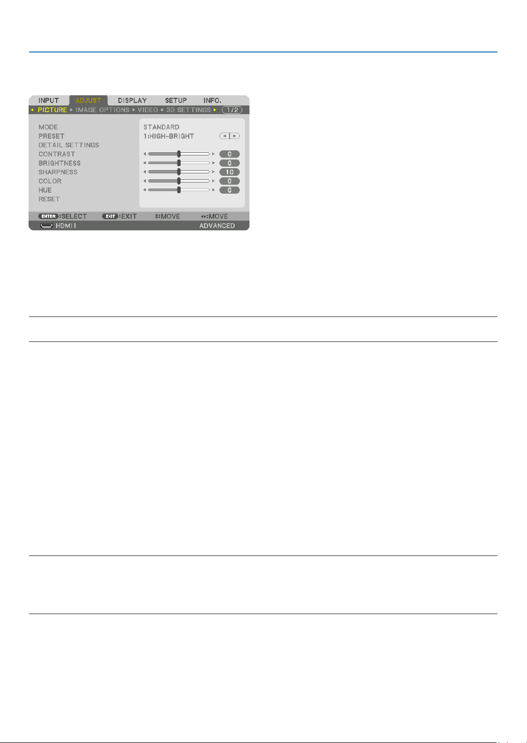
86
5. Using On-Screen Menu
❺ Menu Descriptions & Functions [ADJUST]
[PICTURE]
[MODE]
Thisfunctionallowsyoutodeterminehowtosavesettingsfor[DETAILSETTINGS]of[PRESET]foreachinput.
STANDARD ............ Saves settings for each item of [PRESET] (Preset 1 through 7)
PROFESSIONAL ..... Saves all the settings of [PICTURE] for each input.
NOTE:
•When[TESTPATTERN]isdisplayed,[MODE]cannotbeselected.
[PRESET]
Thisfunctionallowsyoutoselectoptimizedsettingsforyourprojectedimage.
Youcanadjustneutraltintforyellow,cyanormagenta.
Therearesevenfactorypresetsoptimizedforvarioustypesofimages.Youcanalsouse[DETAILSETTINGS]toset
useradjustablesettingstocustomizeeachgammaorcolor.
Yoursettingscanbestoredin[PRESET1]to[PRESET7].
AUTO ..................... Automatically distinguish the optimal setting for the input signal.
HIGH-BRIGHT ........ Recommended for use in a brightly lit room.
PRESENTATION ..... Recommended for making a presentation using a PowerPoint file.
VIDEO .................... Recommended for typical TV program viewing.
MOVIE ................... Recommended for movies.
GRAPHIC ............... Recommended for graphics.
sRGB ..................... Standard color values
DICOM SIM. .......... Recommended for DICOM simulation format.
NOTE:
•The[DICOMSIM.]optionisfortraining/referenceonlyandshouldnotbeusedforactualdiagnosis.
•DICOMstandsforDigitalImagingandCommunicationsinMedicine.ItisastandarddevelopedbytheAmericanCollegeofRadiol-
ogy(ACR)andtheNationalElectricalManufacturersAssociation(NEMA).
Thestandardspecieshowdigitalimagedatacanbemovedfromsystemtosystem.
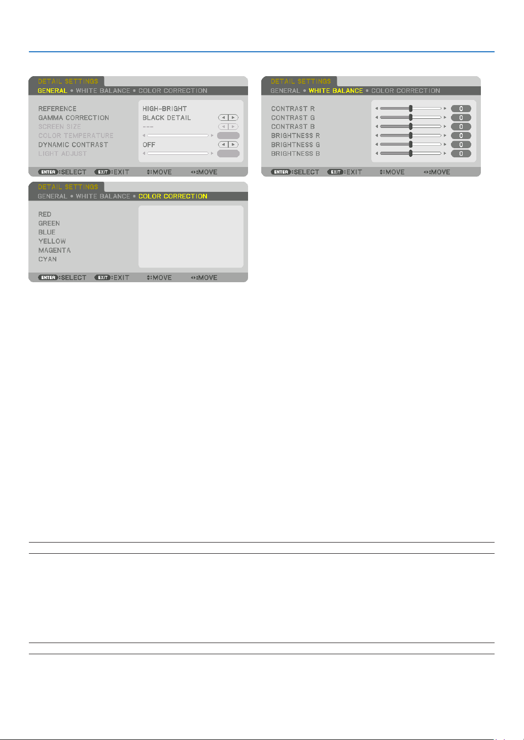
87
5. Using On-Screen Menu
[DETAILSETTINGS]
[GENERAL]
StoringYourCustomizedSettings[REFERENCE]
Thisfunctionallowsyoutostoreyourcustomizedsettingsin[PRESET1]to[PRESET7].
First,selectabasepresetmodefrom[REFERENCE],thenset[GAMMACORRECTION]and[COLORTEMPERA-
TURE].
HIGH-BRIGHT ........ Recommended for use in a brightly lit room.
PRESENTATION ..... Recommended for making a presentation using a PowerPoint file.
VIDEO .................... Recommended for typical TV program viewing.
MOVIE ................... Recommended for movies.
GRAPHIC ............... Recommended for graphics.
sRGB ..................... Standard color values.
DICOM SIM. .......... Recommended for DICOM simulation format.
SelectingGammaCorrectionMode[GAMMACORRECTION]
Eachmodeisrecommendedfor:
DYNAMIC .............. Creates a high-contrast picture.
NATURAL ............... Natural reproduction of the picture.
BLACK DETAIL ....... Emphasizes detail in dark areas of the picture.
NOTE:Thisfunctionisnotavailablewhen[DICOMSIM.]isselectedfor[DETAILSETTINGS].
SelectingScreenSizeforDICOMSIM[SCREENSIZE]
Thisfunctionwillperformgammacorrectionappropriateforthescreensize.
LARGE ................... For screen size of 150"
MEDIUM ................ For screen size of 100"
SMALL ................... For screen size of 50"
NOTE:Thisfunctionisavailableonlywhen[DICOMSIM.]isselectedfor[DETAILSETTINGS].

88
5. Using On-Screen Menu
AdjustingColorTemperature[COLORTEMPERATURE]
Thisoptionallowsyoutoselectthecolortemperatureofyourchoice.
Avaluebetween5000Kand10500Kcanbesetin100Kunits.
NOTE:When[HIGH-BRIGHT]isselectedin[REFERENCE],thisfunctionisnotavailable.
AdjustingBrightnessandContrast[DYNAMICCONTRAST]
Whenset,themostoptimalcontrastratioisadjustedaccordingtothevideo.
OFF ........................ Dynamic contrast is disabled.
MOTION IMAGE ..... Most optimal settings for moving images.
STILL IMAGE ......... Most optimal settings for static images. Rapidly follows any changes in the video.
NOTE:
•Dependingontheconditions,projectorsettingssuchas[DYNAMICCONTRAST]maynotbeabletobeselected.
AdjustingBrightness[LIGHTADJUST]
Theadjustmentiseffectivewhen[PROFESSIONAL]isselectedfor[MODE].
AdjustingWhiteBalance[WHITEBALANCE]
Thisallowsyoutoadjustthewhitebalance.Contrastforeachcolor(RGB)toadjustthewhitelevelofthescreen;
Brightnessforeachcolor(RGB)isusedtoadjusttheblacklevelofthescreen.
[COLORCORRECTION]
Correctsthecolorforallsignals.
Adjuststhetoneforthecolorsred,green,blue,yellow,magentaandcyan.
REDHUE+DirectionMagentadirection
−DirectionYellowdirection
SATURATION+DirectionVivid
−DirectionWeak
GREENHUE
+DirectionYellowdirection
−DirectionCyandirection
SATURATION+DirectionVivid
−DirectionWeak
BLUEHUE
+DirectionCyandirection
−DirectionMagentadirection
SATURATION+DirectionVivid
−DirectionWeak
YELLOWHUE
+DirectionReddirection
−DirectionGreendirection
SATURATION+DirectionVivid
−DirectionWeak
MAGENTAHUE
+DirectionBluedirection
−DirectionReddirection
SATURATION+DirectionVivid
−DirectionWeak
CYANHUE
+DirectionGreendirection
−DirectionBluedirection
SATURATION+DirectionVivid
−DirectionWeak
[CONTRAST]
Adjuststheintensityoftheimageaccordingtotheincomingsignal.
[BRIGHTNESS]
Adjuststhebrightnesslevelorthebackrasterintensity.

89
5. Using On-Screen Menu
[SHARPNESS]
Controlsthedetailoftheimage.
[COLOR]
Increasesordecreasesthecolorsaturationlevel.
[HUE]
Variesthecolorlevelfrom+/−greento+/−blue.Theredlevelisusedasreference.
NOTE:
•When[TESTPATTERN]isdisplayed,[CONTRAST],[BRIGHTNESS],[SHARPNESS],[COLOR]and[HUE]cannotbeadjusted.
[RESET]
Thesettingsandadjustmentsfor[PICTURE]willbereturnedtothefactorydefaultsettingswiththeexceptionofthe
following;Presetnumbersand[REFERENCE]withinthe[PRESET]screen.
Thesettingsandadjustmentsunder[DETAILSETTINGS]withinthe[PRESET]screenthatarenotcurrentlyselected
will not be reset.
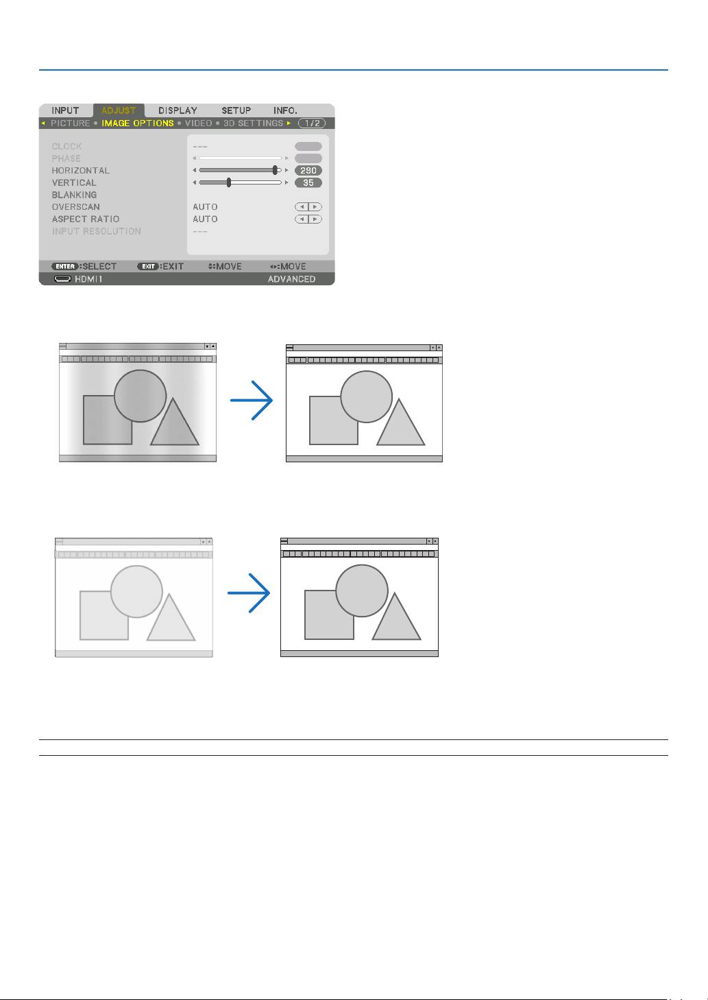
90
5. Using On-Screen Menu
[IMAGE OPTIONS]
AdjustingClockandPhase[CLOCK/PHASE]
ThisallowsyoutomanuallyadjustCLOCKandPHASE.
CLOCK ................... Use this item to fine tune the computer image or to remove any vertical banding that might appear. This
function adjusts the clock frequencies that eliminate the horizontal banding in the image.
This adjustment may be necessary when you connect your computer for the first time.
PHASE ................... Use this item to adjust the clock phase or to reduce video noise, dot interference or cross talk. (This is
evident when part of your image appears to be shimmering.)
Use [PHASE] only after the [CLOCK] is complete.
NOTE:The[CLOCK]and[PHASE]itemsareavailableforRGBsignalsonly.
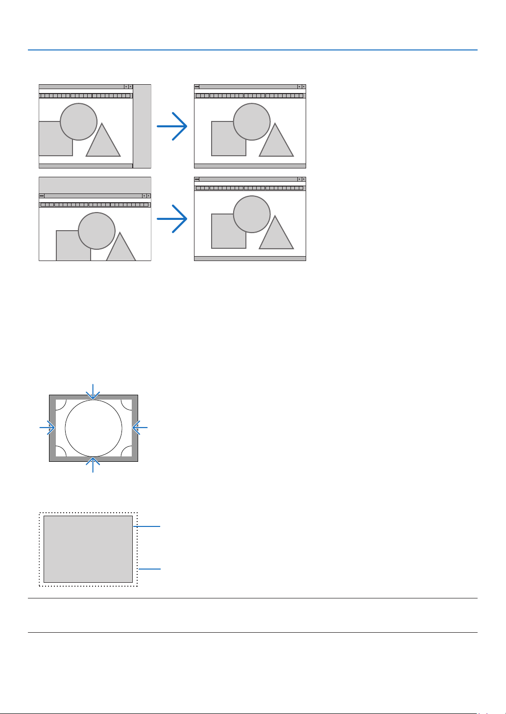
91
5. Using On-Screen Menu
AdjustingHorizontal/VerticalPosition[HORIZONTAL/VERTICAL]
Adjuststheimagelocationhorizontallyandvertically.
•Animagecanbedistortedduringtheadjustmentof[CLOCK]and[PHASE].Thisisnotmalfunction.
•Theadjustmentsfor[CLOCK],[PHASE],[HORIZONTAL],and[VERTICAL]willbestoredinmemoryforthecur-
rentsignal.Thenexttimeyouprojectthesignalwiththesameresolution,horizontalandverticalfrequency,its
adjustments will be called up and applied.
Todeleteadjustmentsstoredinmemory,fromthemenu,youselect[SETUP]→[RESET]→[CURRENTSIGNAL]
and reset the adjustments.
[BLANKING]
Adjuststhedisplayrange(blanking)atthetop,bottom,leftandrightedgesoftheinputsignal.
SelectingOverscanPercentage[OVERSCAN]
Selectoverscanpercentage(Auto,0%,5%and10%)forsignal.
Projected image
Overscaned by 10%
NOTE:
•The[OVERSCAN]itemisnotavailable:
-when[NATIVE]isselectedfor[ASPECTRATIO].
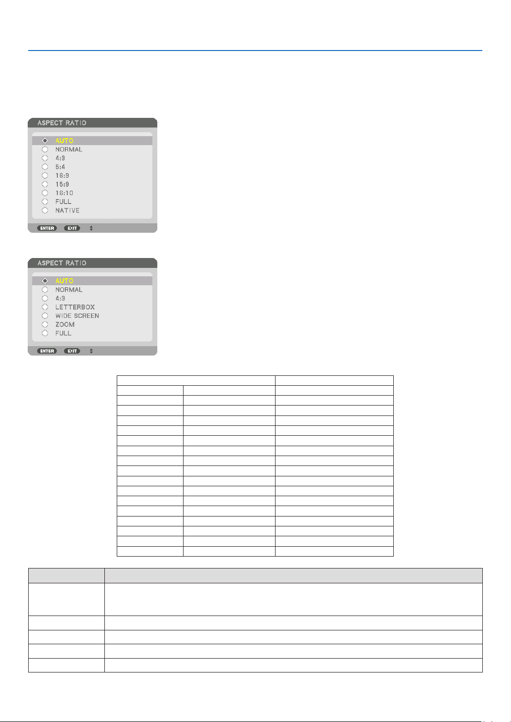
92
5. Using On-Screen Menu
SelectingtheAspectRatio[ASPECTRATIO]
Usethisfunctiontoselectthescreen’slateral:longitudinalaspectratio.
Theprojectorautomaticallyidentiesthesignalbeinginputandsetstheoptimumaspectratio.
For Computer signal
ForHDTV/SDTVsignals
ResolutionAspectRatio
VGA640×4804:3
SVGA
800×6004:3
XGA
1024×7684:3
WXGA
1280×76815:9
WXGA
1280×80016:10
HD(FWXGA)
1366×768approx.16:9
WXGA+1440×90016:10
SXGA
1280×10245:4
SXGA+
1400×10504:3
WXGA++
1600×90016:9
UXGA
1600×12004:3
WSXGA+
1680×105016:10
FHD(1080P)
1920×108016:9
WUXGA
1920×120016:10
WQXGA
2560×160016:10
QuadHD3840×216016:9
QuadHD4096×216019:7
OptionsFunction
AUTO
Theprojectorwillautomaticallydeterminetheincomingsignalanddisplayitinitsaspectratio.
Theprojectormayerroneouslydeterminetheaspectratiodependingonitssignal.Ifthisoccurs,select
theappropriateaspectratiofromthefollowing.
NORMALTheimageisdisplayedinitsoriginalaspectratioofitsinputsignal..
4:3 Theimageisdisplayedin4:3aspectratio.
5:4 Theimageisdisplayedin5:4aspectratio
16:9 Theimageisdisplayedin16:9aspectratio
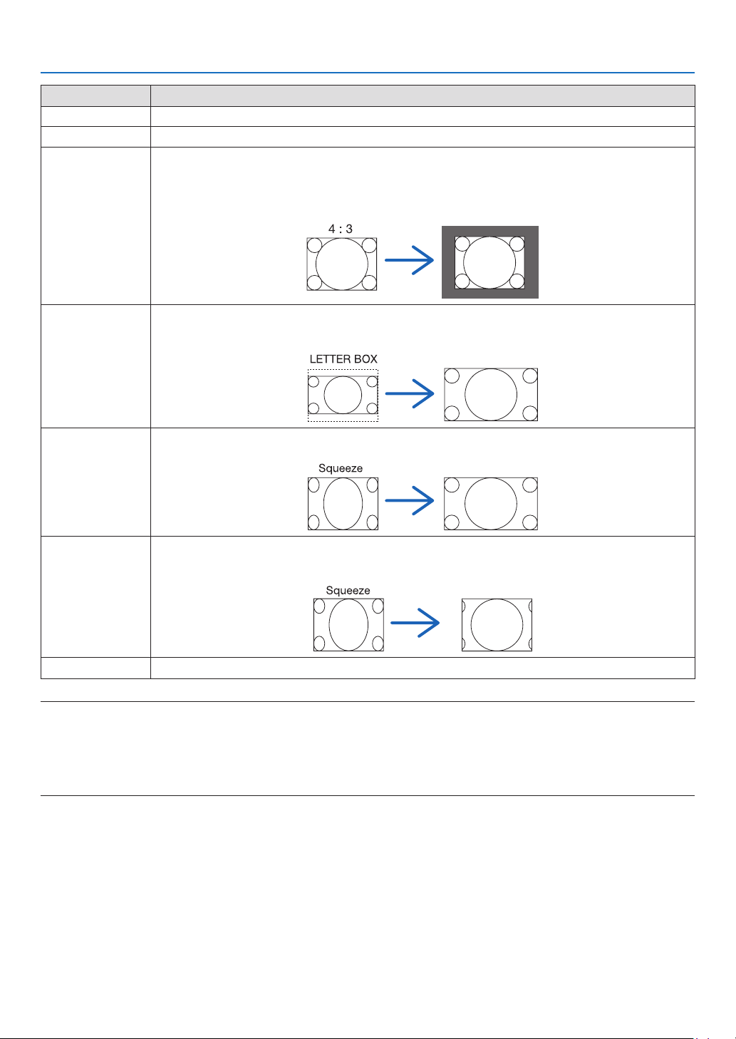
93
5. Using On-Screen Menu
OptionsFunction
15:9
Theimageisdisplayedin15:9aspectratio
16:10 Theimageisdisplayedin16:10aspectratio
NATIVETheprojectordisplaysthecurrentimageinitstrueresolutionwhentheincomingcomputersignalhasa
lowerorhigherresolutionthantheprojector’snativeresolution.(→page
2)
Whentheincomingcomputersignalhasahigherresolutionthantheprojector’snativeresolution,the
centerofanimagewillbedisplayed.
LETTERBOXTheimageofaletterboxsignal(16:9)isstretchedequallyinthehorizontalandverticaldirectionstotthe
screen.
WIDESCREENTheimageofasqueezesignal(16:9)isstretchedleftandrightin16:9.
ZOOMTheimageofasqueezesignal(16:9)isstretchedleftandrightin4:3.
Partsofthedisplayedimagearecroppedattheleftandrightedgesandthereforenotvisible.
FULLProjecttofullscreensize.
TIP:
•Imagepositioncanbeadjustedverticallyusing[POSITION]whenthe[16:9],[15:9],or[16:10]aspectratiosareselected.
•Theterm“letterbox”referstoamorelandscape-orientedimagewhencomparedtoa4:3image,whichisthestandardaspect
ratioforavidesource.
Theletterboxsignalhasaspectratioswiththevistasize“1.85:1”orcinemascopesize“2.35:1”formovielm.
•Theterm“squeeze”referstothecompressedimageofwhichaspectratioisconvertedfrom16:9to4:3.
[INPUTRESOLUTION]
Theresolutionisassignedautomaticallywhentheresolutionoftheinputsignalfromthecomputervideoinputterminal
(analogRGB)cannotbedistinguished.

94
5. Using On-Screen Menu
[VIDEO]
UsingNoiseReduction[NOISEREDUCTION]
Whenprojectingavideoimage,youcanusethe[NOISEREDUCTION]functiontoreducethescreennoise(roughness
anddistortion).Thisdeviceisequippedwiththreetypesofnoisereductionfunctions.Selectthefunctionaccordingto
thetypeofnoise.Dependingonthenoiselevel,thenoisereductioneffectcanbesetto[OFF],[LOW],[MEDIUM]or
[HIGH].[NOISEREDUCTION]canbeselectedforSDTV,HDTVsignalandcomponentsignalinput.
RANDOM NR ......... Reduces flickering random noise in an image.
MOSQUITO NR ...... Reduces mosquito noise that appears around the edges of an image during Blu-ray playback.
BLOCK NR ............. Reduces block noise or mosaic-like patterns.
SelectingInterlacedProgressiveConversionProcessMode[DEINTERLACE]
Thisfunctionallowsyoutoselectaninterlaced-to-progressiveconversionprocessforvideosignals.
NORMAL ................ Automatically distinguishes a moving image from a static image to create a distinct image. Please select
[MOVIE] if there are any obvious jitter and noises.
MOVIE ................... Select when projecting moving images. This is suitable for signals with a lot of jitter and noise.
STILL ..................... Select when projecting static images. The video will flicker when a moving image is projected.
[CONTRASTENHANCEMENT]
Usingthecharacteristicsofthehumaneye,apicturequalitywithasenseofcontrastandresolutionisachieved.
OFF ........................ Suite vision is switched off.
AUTO ..................... Contrast and picture quality are automatically improved using the suite vision function.
NORMAL ................ Adjust the gain manually.

95
5. Using On-Screen Menu
[SIGNALTYPE]
SelectionofRGBandcomponentsignals.Normally,thisissetto[AUTO].Pleasechangethesettingifthecolorof
theimageremainsunnatural.
AUTO ..................... Automatically distinguishes RGB and component signals.
RGB ....................... Switches to the RGB input.
REC601 .................. Switches to the component signal conforming to the ITU-R Rec601 standard.
Setting appropriate to SDTV images.
REC709 .................. Switches to the component signal conforming to the ITU-R Rec709 standard.
Setting appropriate to Hi-Vision images.
REC2020 ................ Switches to the component signal conforming to the ITU-R Rec2020 standard.
Setting appropriate to 4K images.
[VIDEOLEVEL]
SelectionofthevideosignallevelwhenconnectinganexternaldevicetotheHDMI1INterminal,HDMI2INterminal,
DisplayPortinputterminal,andHDBaseTINterminaloftheprojector.
AUTO ..................... The video level is switched automatically based on the information from the device outputting the signal.
Depending on the connected device, this setting may not be made properly. In this case, switch to [NORMAL]
or [ENHANCED] from the menu and view with the optimum setting.
NORMAL ................ This disables the enhanced mode.
ENHANCED ............ This improves the image’s contrast, expressing the dark and light sections more dynamically.
SUPER WHITE ....... The video contrast is improved and the dark areas appear more dynamic.
[HDRMODE]
AUTO ..................... Automatically distinguishes HDR signal.
OFF ........................ Projects the image based on the input signal
ON ......................... Projects the image conforming to the HDR signal
Note:Theseoptionsareavailableexclusivelyfor4Ksignal.

96
5. Using On-Screen Menu
[3D SETTINGS]
Pleasereferto“3-10Projecting3Dvideos”(→page44) for the operation.
STEREOVIEWER
Stackupasingleormultipleprojectorsandcarryoutthesettingsforprojecting3Dvideos.Selecttheleft/rightset-
tingsofthe3Deyewearusingthestereoviewer.
SINGLE .................. Use a single projector to project 3D videos.
DUAL LEFT ............ Use a dedicated projector for displaying videos on the left.
DUAL RIGHT .......... Use a dedicated projector for displaying videos on the right.
STEREO FILTER
Stackupasingleormultipleprojectorsandcarryoutthesettingsforprojecting3Dvideos.Imagesettingfor3D
glassesmadebyIntec.
SINGLE .................. Use a single projector to project 3D videos.
DUAL LEFT ............ Use a dedicated projector for displaying videos on the left.
DUAL RIGHT .......... Use a dedicated projector for displaying videos on the right.
FORMAT
Selectthe3Dvideoformat(recording/transmissionformat).Selecttomatchthe3Dbroadcastand3Dmedia.Nor-
mally,[AUTO]isselected.Pleaseselectthe3Dinputsignalformatwhenthe3Ddetectionsignaloftheformatcannot
bedistinguished.
L/RINVERT
Invertthedisplayorderoftheleftandrightvideos.
Select[ON]ifyoufeeluncomfortablewiththe3Ddisplaywhen[OFF]isselected.
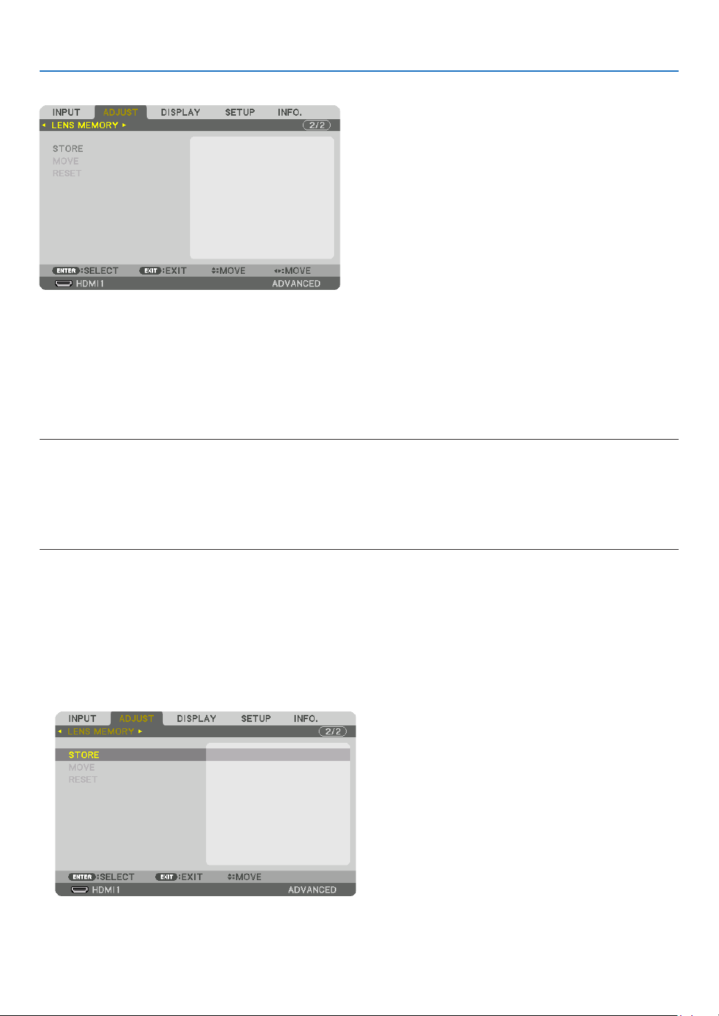
97
5. Using On-Screen Menu
Using the Lens Memory Function [LENS MEMORY]
ThisfunctionservestostoretheadjustedvaluesforeachinputsignalwhenusingtheLENSSHIFT,ZOOMandFO-
CUSbuttonsoftheprojector.Adjustedvaluescanbeappliedtothesignalyouselected.Thiswilleliminatetheneed
toadjustlensshift,focus,andzoomatthetimeofsourceselection.
STORE ................... Stores the current adjusted values in memory for each input signal.
MOVE .................... Applies the adjusted values to the current signal.
RESET .................... Returns the adjusted values to the last condition.
NOTE:
•LensmemoryadjustmentswillbeautomaticallyregisteredtheENTRYLIST.Theselensmemoryadjustmentscanbeloadedfrom
theENTRYLIST.(→page83)
Notethatperforming[CUT]or[ALLDELETE]intheENTRYLISTwilldeletelensmemoryadjustmentsaswellassourceadjust-
ments.Thisdeletionwillnottakeeffectuntilotheradjustmentsisloaded.
•Forstoringeachadjustmentoflensshift,zoomandfocusascommonvalueforallinputsignal,storethemasreferencelens
memory.
Tostoreyouradjustedvaluesin[LENSMEMORY]:
1.Projecttheconnecteddevicesignalyouwanttoadjust.
2.Adjusttheprojectingimageofposition,sizeandfocusbytheSHIFT/HOMEPOSITION,ZOOM+/−,andFOCUS
+/−buttons.
•Adjustmentcanbeperformedbytheremotecontrol.Pleasereferto“2-5AdjustingthePictureSizeandPosi-
tion” on page
20.
•Slightadjustmentbymovingtheprojectorpositionandbythetiltfootisnotsubjectof[LENSMEMORY].
3.Movethecursoron[STORE]andpressENTER.
4.Movethecursoron[YES]andpressENTER.
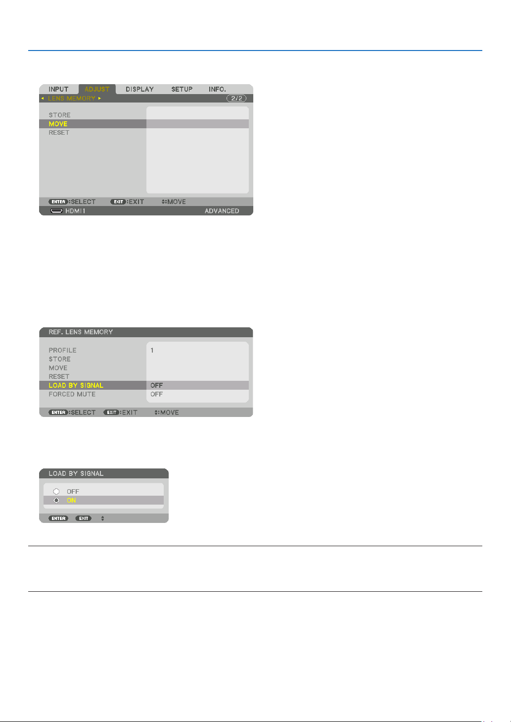
98
5. Using On-Screen Menu
Tocalluptheadjustedvaluesfrom[LENSMEMORY]:
1.Fromthemenu,select[ADJUST]→[LENSMEMORY]→[MOVE]andpresstheENTERbutton.
The confirmation screen will be displayed.
2.Pressthe◀buttontoselectand[YES]andpresstheENTERbutton.
During projection, if the adjusted values for an input signal have been saved, the lens will shift. If not, the lens will
shift according to the adjusted values stored in the selected [REF. LENS MEMORY] [PROFILE] number.
Toautomaticallyapplytheadjustedvaluesatthetimeofsourceselection:
1.Fromthemenu,select[SETUP]→[INSTALLATION(1)]→[REF.LENSMEMORY]→[LOADBYSIGNAL]and
presstheENTERbutton.
2.Pressthe▼buttontoselectand[ON]andpresstheENTERbutton.
This will move the lens automatically to the position at the time of source selection according to the adjusted
values.
NOTE:
•TheLensMemoryfunctionmaynotproduceacompletelyalignedimage(duetotolerancesinthelenses)usingtheadjusted
valuesstoredintheprojector.AftercallingupandapplyingtheadjustedvaluesfromtheLensMemoryfunction,nelyadjustthe
lensshift,zoomandfocustoproducethebestpossibleimage.

99
5. Using On-Screen Menu
❻ Menu Descriptions & Functions [DISPLAY]
[PIP/PICTURE BY PICTURE]
SUBINPUT
Selecttheinputsignaltobedisplayedinthesub-display.
Pleasereferto“4-2DisplayingTwoPicturesattheSameTime”(→page
64) for details on the operation.
MODE
SelecteitherPIP(PICTUREINPICTURE)orPICTUREBYPICTUREwhenswitchingto2-screendisplay.
PICTURE SWAP
Thevideosinthemaindisplayandsub-displaywillbeswitched.
Pleasereferto“4-2DisplayingTwoPicturesattheSameTime”(→page
64) for details.
PIP SETTING
Selectthedisplayposition,positionadjustmentandsizeofthesub-displayinthePIPscreen.
START POSITION ... Selection of the display position of the sub-display when switching to the PIP screen.
HORIZONTAL POSITION
.............................. Adjust the display position of the sub-display in the horizontal direction. The respective corners will serve
as reference points.
VERTICAL POSITION
.............................. Adjust the display position of the sub-display in the vertical direction. The respective corners will serve as
reference points.
SIZE ....................... Select the display size of the sub-display.
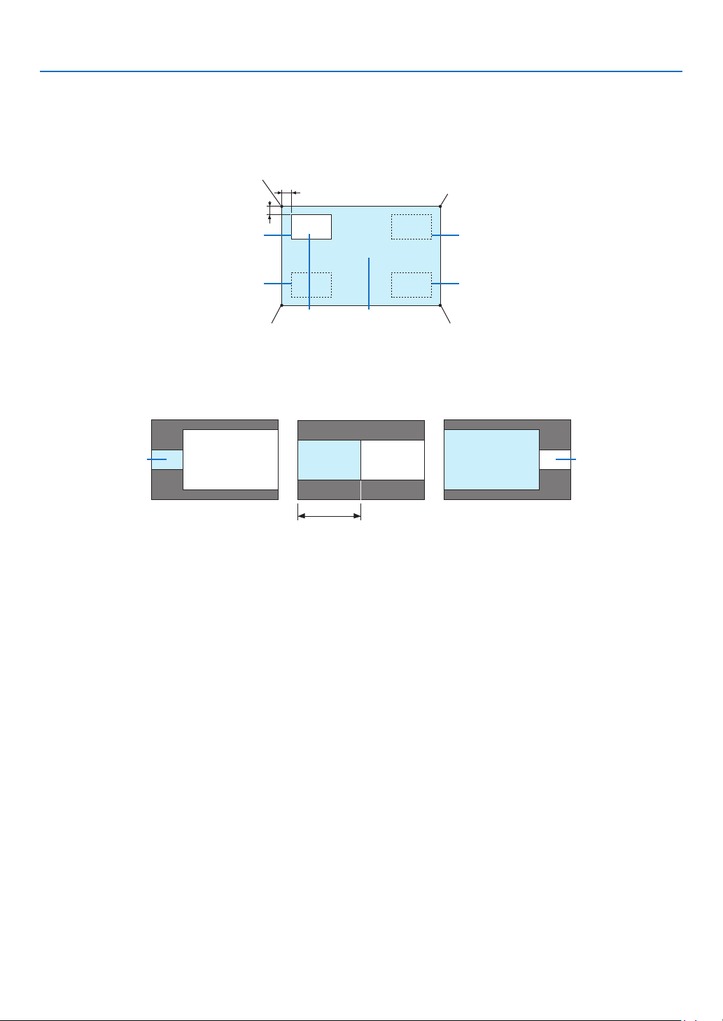
100
5. Using On-Screen Menu
TIP:
Thehorizontalpositionandverticalpositionaretheamountofmovementfromthereferencepoints.Forexample,whenTOP-LEFT
isadjusted,thepositionisdisplayedwiththesameamountofmovementevenifdisplayedwithotherstartingpositions.
Themaximumamountofmovementishalftheresolutionoftheprojector.
Reference point
Adjust using the horizon-
tal position
Sub-display Main display
Reference point
Adjust using the vertical position
TOP-LEFT TOP-RIGHT
BOTTOM-LEFT BOTTOM-RIGHT
Reference pointReference point
BORDER
Selectthedisplayboundaryofthemaindisplayandsub-displayofthe[PICTUREBYPICTURE]screen.
Display boundary
Main display
Sub-displayMain display
Sub-display
Main displaySub-display
TIP:
•Sevenoptionsfromzerotosixareavailable.
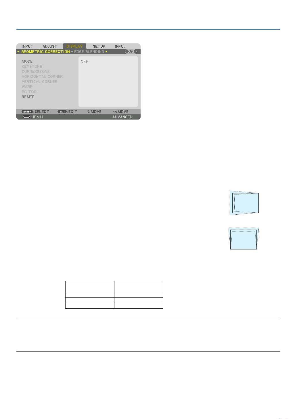
101
5. Using On-Screen Menu
[GEOMETRIC CORRECTION]
MODE
Setpatternforcorrectingdistortion.If[OFF]isselected,the[GEOMETRICCORRECTION]becomesineffective.
Ifyouneedtochangethe[MENUANGLE],makesuretochangeitbeforeperformingthe[GEOMETRICCORREC-
TION].If[MENUANGLE]ischangedafterperformingthe[GEOMETRICCORRECTION],correctedvalueswillbe
reset to the default values.
KEYSTONE
Correctdistortioninhorizontalandverticaldirections.
HORIZONTAL ......... Adjustments when projecting from a diagonal direction to the
screen.
VERTICAL .............. Adjustments when projecting from the top or bottom direction to
the screen.
TILT ....................... Adjusts the distortion when performing trapezoidal correction with the screen moved in the vertical direction
using the lens shift.
THROW RATIO ....... Adjusts according to the projection ratio of the optional lens used.
Model name of lens
unit
Adjustmentrange
NP40ZL 8-11
NP41ZL 13-30
NP42ZL 30-60
NOTE:
•Whenpowerissuppliedtothedevice,theadjustmentvalueofthe[KEYSTONE]usedpreviouslyisretainedevenifthegradient
ofthedeviceischanged.
•Aselectricalcorrectioniscarriedoutby[KEYSTONE],thebrightnessmaybereducedorthescreenqualitymaydeteriorate
sometimes.
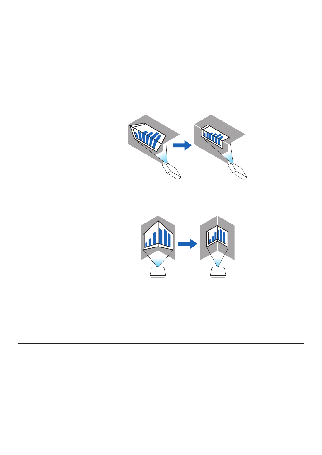
102
5. Using On-Screen Menu
CORNERSTONE
Displaythe4-pointcorrectionscreenandadjustthetrapezoidaldistortionoftheprojectionscreen.
Pleasereferto“CorrectingHorizontalandVerticalKeystoneDistortion[CORNERSTONE]”(→page
36) for details
on the operation.
HORIZONTALCORNER/VERTICALCORNER
Distortioncorrectionforcornerprojectionsuchaswallsurfaces.
HORIZONTAL CORNER
.............................. Performs correction for projection onto a wall lying at an angle to the horizontal direction.
* Reverse angle correction is also possible.
VERTICAL CORNER
.............................. Performs correction for projection onto a wall lying at an angle to the vertical direction.
* Reverse angle correction is also possible.
NOTE:
•Whenthemaximumadjustmentrangeisexceeded,distortionadjustmentisdisabled.Setuptheprojectoratanoptimalangleas
thedeteriorationintheimagequalityincreasesasthedistortionadjustmentvolumegetslarger.
•Pleasenotethattheimagewillgooutoffocusduetothedifferenceinthedistancebetweentheupperandlowerorleftandright
sidesandthecenterofthescreenforprojectionscuttingacrosscorners.Lenseswithshortfocalpointsarealsonotrecommended
forprojectionscuttingacrosscornersastheimagewillgooutoffocus.
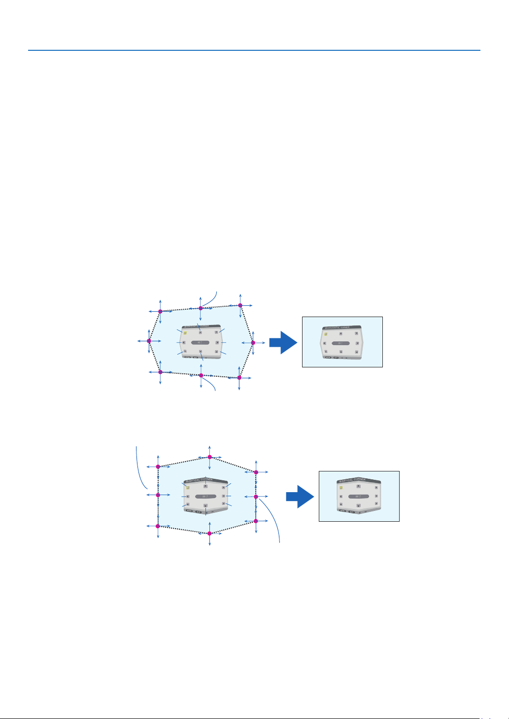
103
5. Using On-Screen Menu
Adjustmentmethod
1.Alignthecursorwiththe[HORIZONTALCORNER]or[VERTICALCORNER]ofthe[GEOMETRICCORREC-
TION]menuandthenpresstheENTERbutton.
•Theadjustmentscreenwillbedisplayed.
2.Pressthe▼▲◀▶buttonstoalignthecursor(yellowbox)withthetargetadjustmentpointandthenpress
theENTERbutton.
•Thecursorwillchangeintoanadjustmentpoint(yellowincolor).
3.Pressthe▼▲◀▶buttonstoadjustthecornersorsidesofthescreenandthenpresstheENTERbutton.
•Theadjustmentpointwillgobacktobeingacursor(yellowbox).
Explanation of screen transition
•Theadjustmentpointsofthefourcorners(a,c,fandhinthedrawing)willmoveindependently.
•Thefollowingadjustmentpointsdifferatthe[HORIZONTALCORNER]and[VERTICALCORNER].
HORIZONTAL CORNER: When Point b in the drawing is moved, and the upper side and Point g are moved,
the lower side will move in a parallel manner.
VERTICAL CORNER: When Point d in the drawing is moved, and the left side and Point e are moved, the right
side will move in a parallel manner.
[Adjustment points of the [HORIZONTAL CORNER] screen and movement points of the projection screen]
a
b
b
c
d
e
f
g
h
a
c
d
e
f
g
h
Point b will be displaced in a parallel manner at the same time as Points a, b, c
Point g will be displaced in a parallel manner at the same time as Points f, g, h
[Adjustment points of the [VERTICAL CORNER] screen and movement points of the projection screen]
a
a
b
b
c
c
d
d
e
e
f
f
g
g
h
h
Point d will be displaced in a parallel manner at the same time as Points a, d, f
Point e will be displaced in a parallel manner at the same time as Points f, g, h
4.StartfromStep2onwardstoadjusttheotherpoints.
5.Whentheadjustmentiscompleted,pressthe▼▲◀▶buttonstoalignthecursorwiththe[EXIT]inthead-
justmentscreenandthenpresstheENTERbutton.
•Switchtothe[GEOMETRICCORRECTION]menuscreen.
TIP:
AcommerciallyavailableUSBmouseisavailabletoperformcorrection.(→page
38)
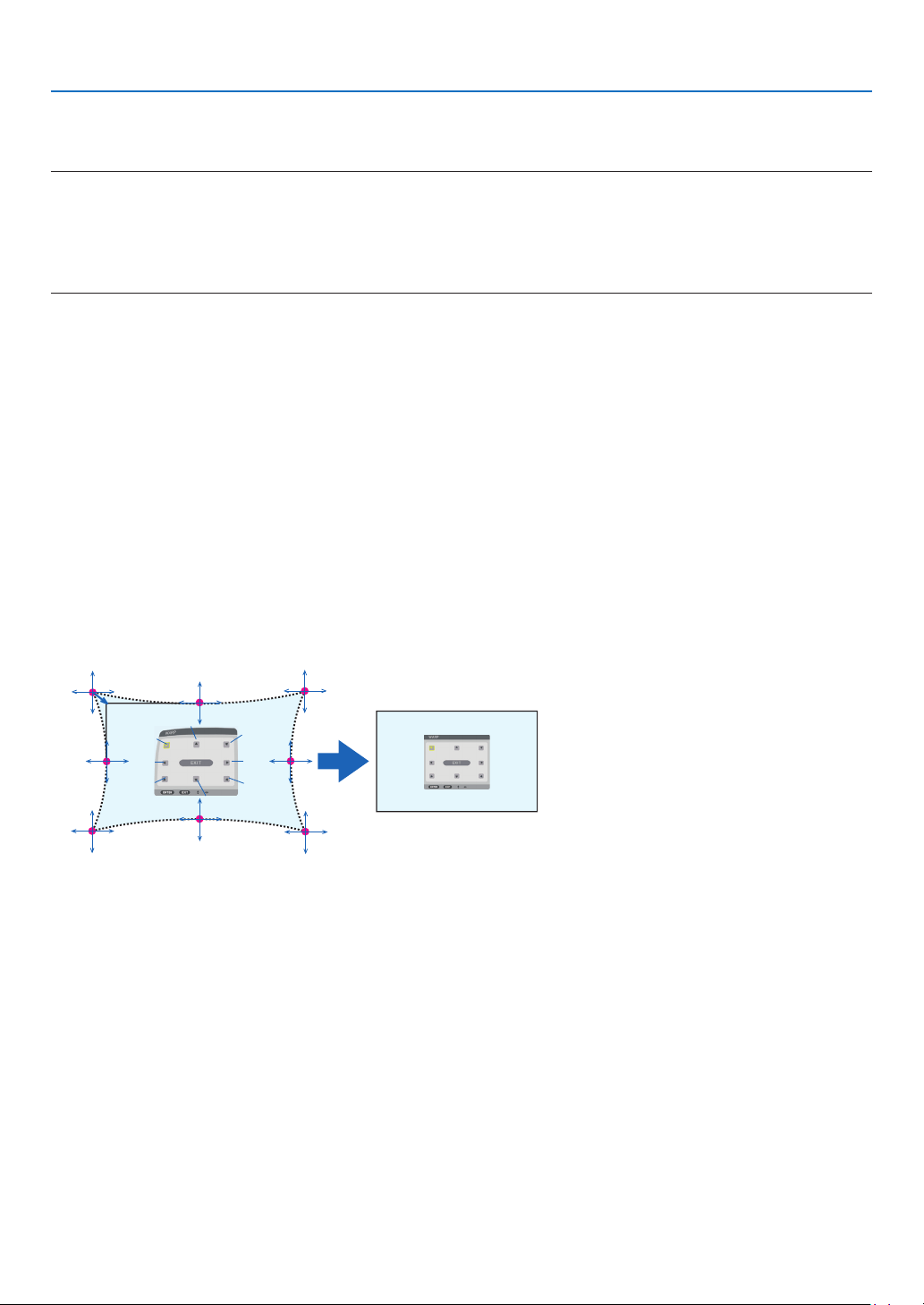
104
5. Using On-Screen Menu
WARP
Correctprojectedimagedistortiononaspecicsurfaceasacolumnorasphere.
NOTE:
•Whenthemaximumadjustmentrangeisexceeded,distortionadjustmentisdisabled.Setuptheprojectoratanoptimalangle
sincethemoretheadjustmentvolumegetslarge,themoreimagequalitygetsdeterioration.
•Pleasenotethattheimagewillgooutoffocusduetothedifferenceinthedistancebetweenperipheriesandthecenterofthescreen
forprojectionscuttingacrosscornersasonacolumnorasphere.Lenseswithshortfocalpointsarealsonotrecommendedfor
projectionscuttingacrosscornersastheimagewillgooutoffocus.
Adjustmentmethod
1.Alignthecursorwiththe[WARP]ofthe[GEOMETRICCORRECTION]menuandthepresstheENTER.
•Adjustmentscreenwillbedisplayedon.
2.Pressthe▼▲◀▶buttonstoalignthecursor(bluebox)withthetargetadjustmentpointandthenpressthe
ENTER.
•Thecursorwillchangeintoanadjustmentpoint(yellowincolor).
3.Pressthe▼▲◀▶buttonstoadjustthecornersorsidesofthescreenandthenpresstheENTER.
•Thecursorwillbacktoyellowbox.
Explanation for correcting distortion
•Eightadjustmentpointscanbemovedindependently.
•Forleftandrightsides,use◀/▶ buttons for adjusting the range of distortion, and ▼/▲ buttons for adjusting
the distortion peak.
•Fortopandbottomsides,use▼/▲ buttons for adjusting the range of distortion, and ◀/▶ buttons for adjusting
the distortion peak.
•Forcorners,use▼▲◀▶ buttons for moving positions.
a
b
c
e
h
d
g
f
b
a
c
d
e
f
g
h
4.Foradjustingotherpoints,repeatStep2onwards.
5.Whentheadjustmentiscompleted,movethecursorontothe[EXIT]ontheadjustmentscreenandpress
theENTER.
•Thescreenwillbeswitchedtothe[GEOMETRICCORRECTION]menu.
The adjustment completion screen will be displayed on.
6.Press◀ or ▶buttontomovethecursoronto[OK]thenpress[ENTER].
•TheadjustedvaluesforWARParestoredandthescreendisplaygoesbacktothe[GEOMETRICCORREC-
TION].
TIP:
AcommerciallyavailableUSBmouseisavailabletoperformcorrection.(→page
38)

105
5. Using On-Screen Menu
PC TOOL
Recallthegeometriccorrectiondatathatisregisteredintheprojectorbeforehand.
Threetypesofcorrectiondatacanberegistered.
NOTE:
• Aselectricalcorrectioniscarriedoutingeometriccorrection,thebrightnessmaybeaffectedandthepicturequalitymaybe
degraded.
RESET
ResettheadjustmentvaluethathasbeensetupasMODEinGEOMETRICCORRECTION(returntotheinitialvalue).
•ThisisineffectivewhenMODEissetOFF.
•ResetcanbeexecutedbypressingandholdingtheGeometeric.buttonontheremotecontrolforover2seconds.

106
5. Using On-Screen Menu
[EDGE BLENDING]
Thisadjuststheedges(boundaries)oftheprojectionscreenwhenprojectinghighresolutionvideosusingacombina-
tionofseveralprojectorsintheup,down,leftandrightpositions.
MODE
ThisenablesordisablestheEDGEBLENDINGfunction.
WhenMODEissettoON,theTOP,BOTTOM,LEFT,RIGHT,BLACKLEVELandBLENDCURVEsettingscanbe
adjusted.
TOP/BOTTOM/LEFT/RIGHT
ThisselectstheEDGEBLENDINGlocationsontheleft,right,topandbottomonthescreen.
Thefollowingsettingscanbeadjustedwhenanitemisselected.(→page
69)
CONTROL .............. Enable TOP, BOTTOM, LEFT and RIGHT functions.
MARKER ................ Set whether to display marker or not when adjusting the range and display position. When turned on, a
magenta marker for adjusting the range adjustment and a green marker for adjusting the display position
will be displayed.
RANGE ................... Adjust the range (width) of the edge blending.
POSITION .............. Adjust the display position of the edge blending.
BLACKLEVEL
Dividethescreenintoninepartsandkeeptheblackleveluniformforeachprojector.
TheninedivisionsscreensareTOP-LEFT,TOP-CENTER,TOP-RIGHT,CENTER-LEFT,CENTER,CENTER-RIGHT,
BOTTOM-LEFT,BOTTOM-CENTERandBOTTOM-RIGHT.(→page
72)
BLENDCURVE
SetbrightnessfortheEDGEBLENDINGsections.(→page
71)

107
5. Using On-Screen Menu
[MULTI SCREEN]
WHITEBALANCE
Thisadjuststhewhitebalanceforeachprojectorwhenprojectingusingacombinationofseveralprojectors.
Thiscanbeadjustedwhen[MODE]issetto[ON].
CONTRAST W, CONTRAST R, CONTRAST G, CONTRAST B
.............................. Adjusting the white color of the video.
BRIGHTNESS W, BRIGHTNESS R, BRIGHTNESS G, BRIGHTNESS B
.............................. Adjusting the black color of the video.
PICTURE SETTING
Thissetsthedivisionconditionwhenprojectingusingacombinationofseveralprojectors.
Pleasereferto“4.Multi-ScreenProjection”(→page
60) for details.
MODEOFFUse the projector in a standalone state.
ZOOMThisadjuststhepositionandwidthofthevideoareathatyouwishtodivide.Theedge
blendingwidthwillalsobeautomaticallysettothatwidth.
TILINGThisassignsthedividedscreenstotheprojectors.Theedgeblendingfunctionwillalso
be set automatically.
ZOOMHORIZONTAL
ZOOM
Thisenlargesthevideoareainthehorizontaldirection.
VERTICAL
ZOOM
Thisenlargesthevideoareaintheverticaldirection.
HORIZONTAL
POSITION
Thisshiftsthevideoareainthehorizontaldirection.
VERTICALPO-
SITION
Thisshiftsthevideoareaintheverticaldirection.
TILINGWIDTHThisselectsthenumberofprojectorstobearrangedhorizontally.
HEIGHTThisselectsthenumberofprojectorstobearrangedvertically.
HORIZONTAL
POSITION
Thisselectsthepositionoftheprojectorstartingfromtheleftamongthosearranged
horizontally.
VERTICALPO-
SITION
Thisselectsthepositionoftheprojectorstartingfromthetopamongthosearranged
vertically.
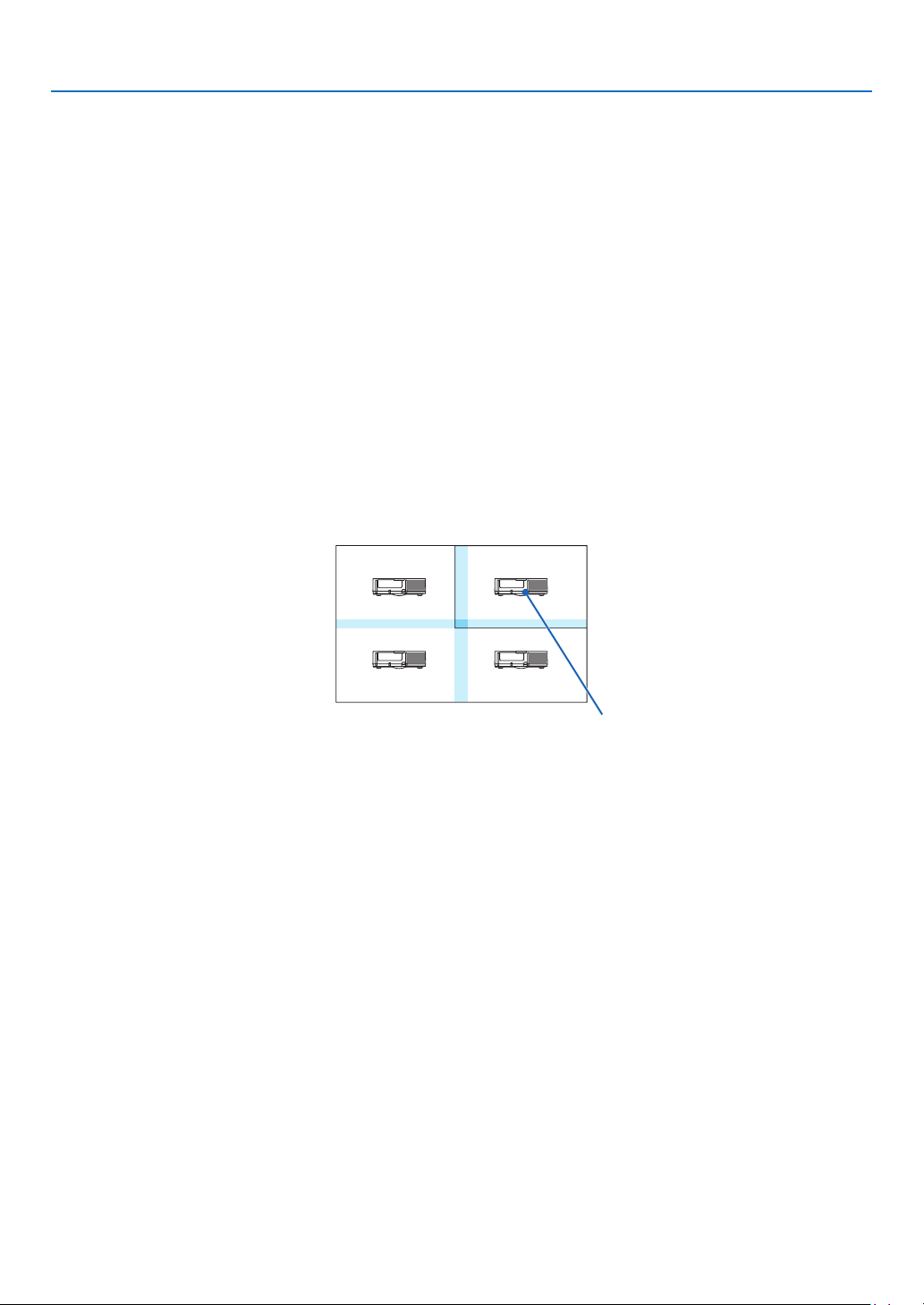
108
5. Using On-Screen Menu
Conditionsforusingtiling
•Alltheprojectorsneedtofullthefollowingconditions.
•Thepanelsizemustbethesame
•Theprojectionscreensizemustbethesame
•Theleftandrightendsortopandbottomendsoftheprojectionscreenmustbeconsistent.
•Thesettingsfortheleftandrightedgesoftheedgeblendingarethesame
•Thesettingsforthetopandbottomedgesoftheedgeblendingarethesame
Ifthetilingconditionsaresatised,thevideoscreenoftheprojectorateachinstallationpositionwillbeautomati-
callyextractedandprojected.
Ifthetilingconditionsarenotsatised,adjustthevideoscreenoftheprojectorateachinstallationpositionusing
thezoomfunction.
•AssignauniquecontrolIDtoeachprojector.
•Setthe“Colorsetting”and“DeepColorsetting”onyourBlu-rayplayerorcomputerto“Auto”.Refertotheowner’s
manualaccompaniedwithyourBlu-rayplayerorcomputerformoreinformation.ConnectanHDMIoutputsignal
ofyourBlu-rayplayerorcomputertotherstprojectorandthenconnecttotheHDBaseTOUT/Ethernetporton
therstprojectortotheHDBaseTIN/Ethernetportonthesecondprojector,sametothesequelprojectors..
Tilingsettingexample)Numberofhorizontalunits=2,Numberofverticalunits=2
Horizontal order = Second unit
Vertical order = First unit
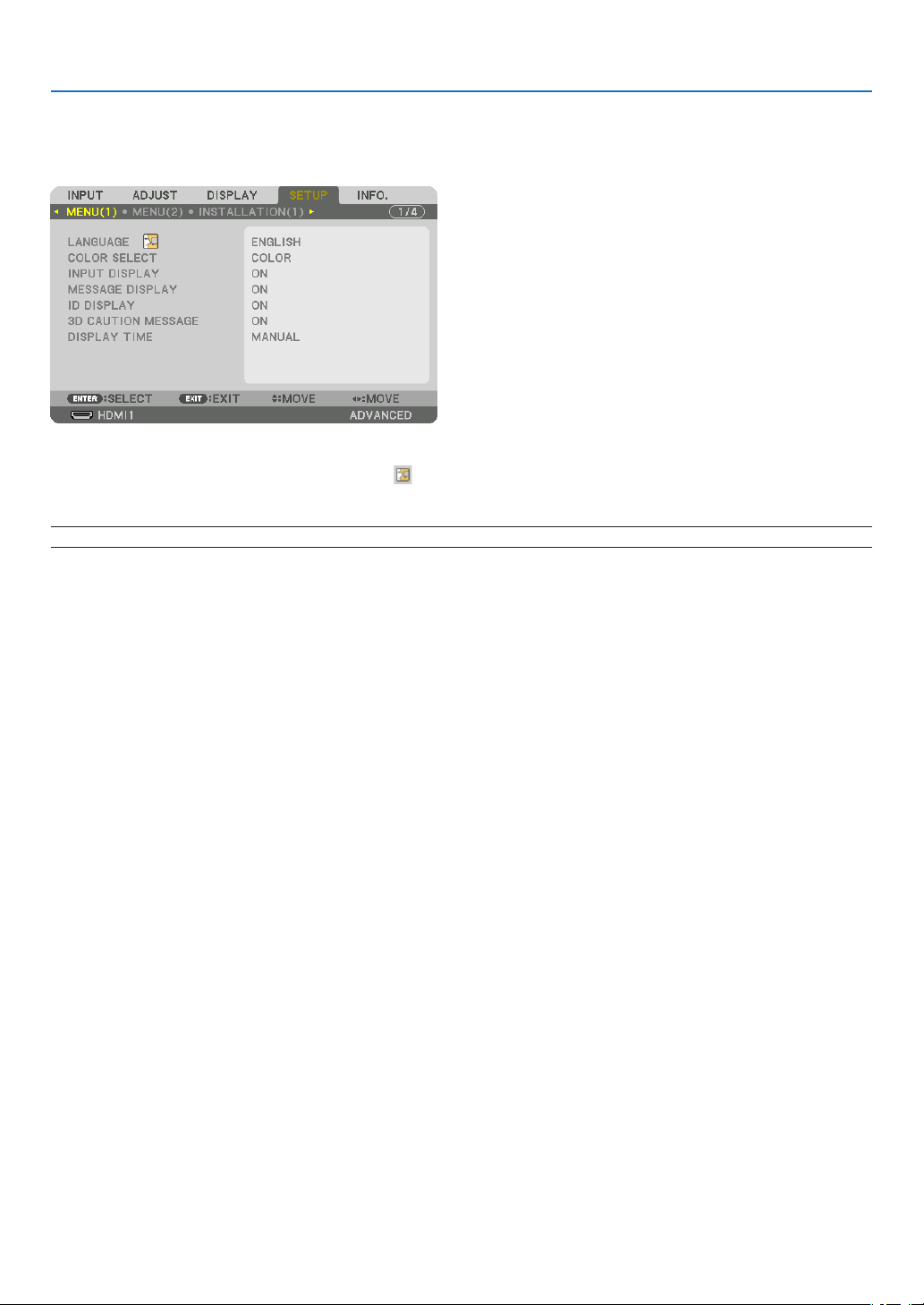
109
5. Using On-Screen Menu
❼ Menu Descriptions & Functions [SETUP]
[MENU(1)]
SelectingMenuLanguage[LANGUAGE]
Youcanchooseoneof30languagesforon-screeninstructions.
NOTE:Yoursettingwillnotbeaffectedevenwhen[RESET]isdonefromthemenu.
SelectingMenuColor[COLORSELECT]
Youcanchoosebetweentwooptionsformenucolor:COLORandMONOCHROME.
TurningOn/OffSourceDisplay[INPUTDISPLAY]
ThisoptionturnsonoroffinputnamedisplaysuchasHDMI1,HDMI2,DisplayPort,COMPUTER,HDBaseTtobe
displayedonthetoprightofthescreen.
Turningmessagesonandoff[MESSAGEDISPLAY]
Thisoptionselectswhetherornottodisplayprojectormessagesatthebottomoftheprojectedimage.
Evenwhen“OFF”isselected,thesecuritylockwarningisdisplayed.Thesecuritylockwarningturnsoffwhenthe
securitylockiscanceled.
TurningON/OFFControlID[IDDISPLAY]
ID DISPLAY ........... This option turns on or off the ID number which is displayed when the ID SET button on the remote control
is pressed. (→ page
121)
[3DCAUTIONMESSAGE]
Thisselectswhethertodisplayacautionmessageornotwhenswitchingtoa3Dvideo.
ThedefaultconditionwhenshippedfromthefactoryisON.
OFF ........................ The 3D caution message screen will not be displayed.
ON ......................... The 3D caution message screen will be displayed when switching to a 3D video. Press the ENTER button
to cancel the message.
•Themessagewilldisappearautomaticallyafter60secondsorwhenotherbuttonsarepressed.Ifitdisap-
pears automatically, the 3D caution message will be displayed again when switching to a 3D video.
SelectingMenuDisplayTime[DISPLAYTIME]
Thisoptionallowsyoutoselecthowlongtheprojectorwaitsafterthelasttouchofabuttontoturnoffthemenu.The
presetchoicesare[MANUAL],[AUTO5SEC],[AUTO15SEC],and[AUTO45SEC].The[AUTO45SEC]isthe
factory preset.

110
5. Using On-Screen Menu
[MENU(2)]
[MENUANGLE]
Selectthedirectionfordisplayingthemenu.
[MENUPOSITION]
Shiftthemenudisplayingposition.
HORISONTAL POSITION .....Shift the menu in the horizontal directions.
VERTICAL POSITION ..........Shift the menu in the vertical directions.
RESET .................................Reset the menu displaying position to the default factory setting (the screen center).
TIP
•Oncetheprojectorispoweredoff,themenudisplayingpositionwillresettothedefaultfactorysetting.
•Inputterminalandmessagedisplayingpositionarenotinuencedbythe[MENUPOSITION].
•ItenablestomovethemenubymouseclickwhenacommerciallyavailableUSBmouseisconnected.
•Itenablestomovethemenupositionbythe▼▲◀and▶buttonsholdingtopresstheCTLbuttonontheremotecontrolor
mouseclick.
•WhiletheMENUPOSITIONoftheon-screenmenuisdisplayedonandthemenuismovedbythe▼▲◀and▶buttonsholdingto
presstheCTLbuttonontheremotecontrolorbymouseclick,theindicationofadjustedvalueonthemenuwillnotbechanged.
Inthiscase,closetheMENUPOSITIONmenuonceanddisplayitagainforindicatingtheadjustedvalueproperly.
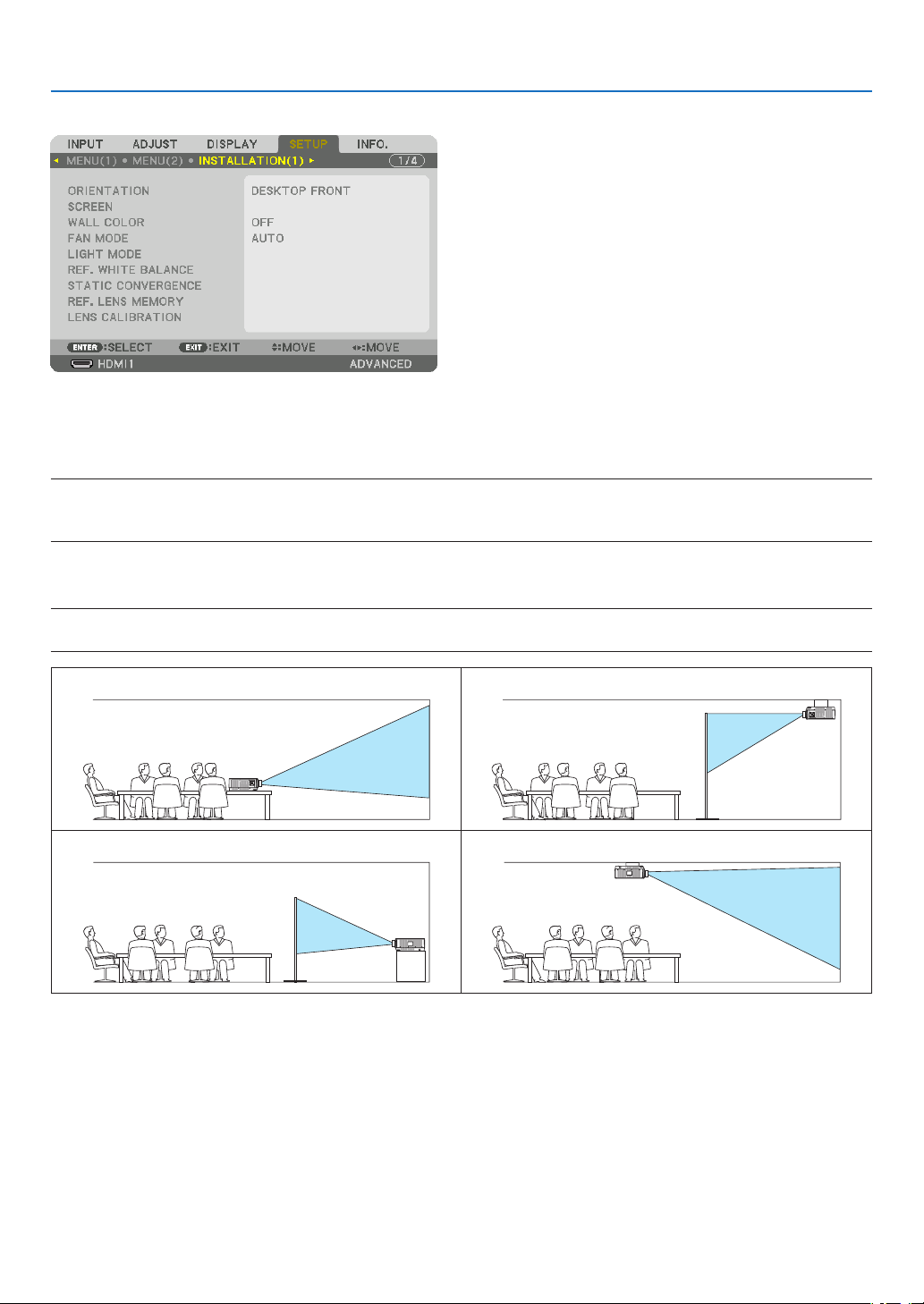
111
5. Using On-Screen Menu
[INSTALLATION(1)]
SelectingProjectorOrientation[ORIENTATION]
Thisreorientsyourimageforyourtypeofprojection.Theoptionsare:desktopfrontprojection,ceilingrearprojection,
desktoprearprojection,andceilingfrontprojection.
NOTE:
•Pleaseconsultthedealerifyourequirespecialinstallationservicese.g.whenmountingtheprojectortoaceiling.Neverinstall
theprojectoronyourown.Thismayresultintheprojectorfallingdownandcausinginjurytopeople.
AUTO ..................... This automatically detects and projects the DESKTOP FRONT and CEILING FRONT.
NOTE:
•TheDESKTOPREARandCEILINGREARwillnotbedetected.Pleaseselectmanually.
DESKTOPFRONTCEILINGREAR
DESKTOPREARCEILINGFRONT
TIP:
•CheckwhethertheautomaticDESKTOPFRONTisinstalledwithin±10degreesforoorinstallationandwhethertheCEILING
FRONTiswithin±10degreesforceilinginstallation.Selectmanuallywhentheprojectionscreenisinverted.
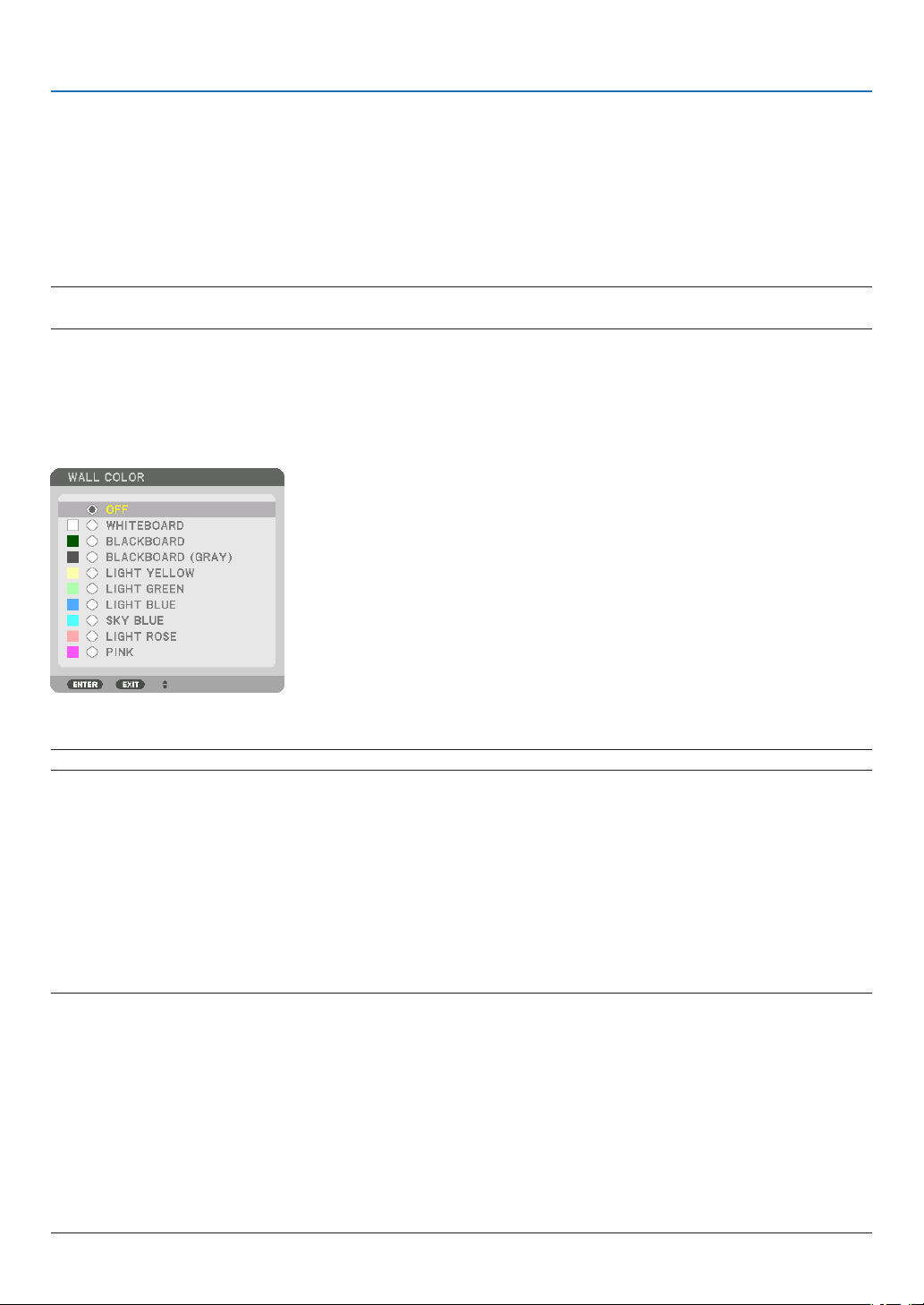
112
5. Using On-Screen Menu
SelectingAspectRatioandPositionforScreen[SCREEN]
[SCREENTYPE]
Setstheaspectratiooftheprojectionscreen.
FREE ...................... The ratio of the liquid crystal panel is selected. Select this when projecting multi-screen and 17:9 screen
(2K).
4:3 SCREEN ........... For a screen with a 4:3 aspect ratio
16:9 SCREEN ......... For a screen with a 16:9 aspect ratio
16:10 SCREEN ....... For a screen with a 16:10 aspect ratio
NOTE:
•
Afterchangingthescreentype,checkthesettingof[ASPECTRATIO]inthemenu.(→page
92)
[POSITION]
Adjustthescreenposition.Dependingonthemodelyouuseandthescreentype,thefunctionmaybecomeineffec-
tiveandtheadjustablerangemayvary.
UsingtheWallColorCorrection[WALLCOLOR]
Thisfunctionallowsforquickadaptivecolorcorrectioninapplicationswherethescreenmaterialisnotwhite.
NOTE:Selecting[WHITEBOARD]reduceslightsourcebrightness.
SelectingFanMode[FANMODE]
FanModeisusedtosetthespeedoftheinternalcoolingfan.
MODE .................... Select one among four modes: AUTO, NORMAL, HIGH, and HIGH ALTITUDE.
AUTO: The built-in fans automatically run at variable speed according to the detected temperature and
atmospheric pressure by the built-in sensor.
NORMAL: The built-in fans run at the appropriate speed based on the detection by the built-in temperature
sensor.
HIGH: The built-in fans run at high speed
HIGH ALTITUDE: The built-in fans run at high speed. Select this option when using the projector at altitudes
approximately 5500 feet/1700 meters or higher.
NOTE:
•Makesurethespeedissetto[HIGH]whenyouareusingthisdevicecontinuouslyforseveraldays.
•Set[FANMODE]to[AUTO]or[HIGHALTITUDE]whenusingtheprojectorataltitudesapproximately5500feet/1700metersor
higher.
•Usingtheprojectorataltitudesapproximately5500feet/1700metersorhigherwithoutsettingto[AUTO]or[HIGHALTITUDE]
cancausetheprojectortooverheatandtheprotectorcouldshutdown.Ifthishappens,waitacoupleminutesandturnonthe
projector.
•Usingtheprojectorataltitudeslessthanapproximately5500feet/1700metersandsettingto[HIGHALTITUDE]cancausethe
projectortoovercool,causingtheimagetoicker.Switch[FANMODE]to[AUTO].
•Usingtheprojectorataltitudesapproximately5500feet/1700metersorhighercanshortenthelifeofopticalcomponentssuch
asthelightsource.
•Yoursettingwillnotbeaffectedevenwhen[RESET]isdonefromthemenu.

113
5. Using On-Screen Menu
TIP:
•When[HIGHALTITUDE]isselectedfor[FANMODE],asymbolicon
willbedisplayedatthebottomofthemenu.
[LIGHTMODE]
Adjustingtheenergysavingssettingsandthebrightnessofeachprojectorinmulti-screenprojection.Forenergy
savingssettings,seepage
33“3-6.ChangingLIGHTMODE/CheckingEnergy-SavingEffectUsingLIGHTMODE
[LIGHTMODE]”.
LIGHTMODENORMALThelightmoduleluminance(brightness)willbecome100%andthescreenwillturnbright.
ECO1Bycontrollingthebrightnessandfanspeedaccordingtotheselectedsetting,energycan
be saved and motion noise and the power consumption can be lowered.
ECO2
LONGLIFEThemodeoptimizestheservicelifeoftheoptimalparts.Thebrightnessisabout30%of
NORMAL.
CONSTANT
BRIGHTNESS
OFF[CONSTANTBRIGHTNESS]modewillbecanceled.
ONMaintainsthebrightnessthatisineffectatthetime[ON]isselected.Unless[OFF]isse-
lected,thesamesettingswillremainineffectevenwhentheprojectoristurnedoff.
•Tore-adjustthebrightness,rstturnthissettingOFFbeforemakingfurtheradjustments.
NOTE:
•[CONSTANTBRIGHTNESS]modeisafunctionusedtomaintainthebrightnessataconstant
level.Colorwillnotbexed.
REF.LIGHTADJUSTBrightnesscanbeadjustedin1%incrementsfrom25to100%.
Whenseveralprojectorsareusedformulti-screenprojection,thebrightnesscanbead-
justed individually on each projector.
*[LIGHTMODE]isavailablewhen[OFF]isselectedfor[CONSTANTBRIGHTNESS].
*[REF.LIGHTADJUST]isavailablewhen[NORMAL]isselectedfor[LIGHTMODE]and[OFF]isselectedfor[CONSTANT
BRIGHTNESS].
TIP:
•Brightnessnormallydecreaseswithuse,butbyselecting[CONSTANTBRIGHTNESS]mode,sensorsinsidetheprojectordetect
brightnessandautomaticallyadjusttheoutput,therebymaintainingaconstantbrightnessthroughoutthelifeofthelightmodule.
However,ifoutputisalreadyatitsmaximum,brightnesswilldecreasewithuse.
Forthisreason,whenusingmulti-screenprojection,itisrecommendedtoadjustthebrightnesstoaslightlylowerlevel,then
settingthe[CONSTANTBRIGHTNESS]modeto[ON].
[REF.WHITEBALANCE]
Thisfeatureallowsyoutoadjustthewhitebalanceforallsignals.
Thewhiteandblacklevelsofthesignalareadjustedforoptimumcolorreproduction.
Uniformityisalsoadjustedwhentheredness(R)andblueness(B)ofthewhitecolorinthescreen’shorizontal(left/
right)directionareuneven.
CONTRAST R/CONTRAST G/CONTRAST B ...............These adjust the picture’s white color.
BRIGHTNESS R/BRIGHTNESS G/BRIGHTNESS B ....These adjust the picture’s black color.
UNIFORMITY R ......................................................... The further this is set to the + side, the stronger the redness on the left side
of the picture (increasing towards the left edge) and the weaker the redness
on the right side of the picture (decreasing towards the right edge).
This is reversed when set to the – side.
UNIFORMITY B .........................................................The further this is set to the + side, the stronger the blueness on the left side
of the picture (increasing towards the left edge) and the weaker the blueness
on the right side of the picture (decreasing towards the right edge).
This is reversed when set to the – side.

114
5. Using On-Screen Menu
[STATICCONVERGENCE]
Thisfeaturesallowsyoutoadjustforcolordeviationinthepicture.
Thiscanbeadjustedinunitsof±1pixelinthehorizontaldirectionforHORIZONTALR,GandB,intheverticaldirec-
tionforVERTICALR,GandB.
UsingtheReferenceLensMemoryFunction[REF.LENSMEMORY]
ThisfunctionservestostoretheadjustedvaluescommontoallinputsourceswhenusingtheLENSSHIFT,ZOOM
andFOCUSbuttonsoftheprojectorortheremotecontrol.Theadjustedvaluesstoredinmemorycanbeusedasa
reference to the current.
PROFILE ................ Select a stored [PROFILE] number.
STORE ................... Stores the current adjusted values in memory as a reference.
MOVE .................... Applies the adjusted reference values stored in [STORE] to the current signal.
RESET .................... Reset selected [PROFILE] number [REF. LENS MEMORY] to the factory default settings.
LOAD BY SIGNAL .. When you switch signals the lens will shift to the lens shift, zoom, and focus values for the selected [PRO-
FILE] number.
If no adjusted values have been saved to [LENS MEMORY], the lens will apply [REF. LENS MEMORY]
adjusted values. Alternatively, if no adjusted values have been saved to [REF. LENS MEMORY], the unit will
return to factory default settings.
FORCED MUTE ...... To turn off the image during lens shift, select [YES].
NOTE:
•Adjustedvaluesin[REF.LENSMEMORY]willnotbereturnedtodefaultwhenperforming[CURRENTSIGNAL]or[ALLDATA]for
[RESET]fromthemenu.
•Tostoreadjustedvaluesforeachinputsource,usetheLensMemoryfunction.(→page
54,97)
[LENSCALIBRATION]
Theadjustmentrangeofthezoom,focus,andshiftofthemountedlensiscalibrated.
Besuretocarryout[LENSCALIBRATION]afterreplacingthelens.

115
5. Using On-Screen Menu
[INSTALLATION(2)]
[SHUTTERSETTINGS]
Enablinganddisablingthelensshutterfunction.Youcanalsosethowlongthelightwilltaketofadeinandfadeout
wheneithertheSHUTTERbuttonontheremotecontrol.
POWERON
SHUTTER
OPENWhenthepoweristurnedon,thelightsourcecomesonandthepictureis
projected.
CLOSE
Thelightsourcedoesnotcomeonwhenthepoweristurnedon.
WhentheSHUTTERbuttonispressed,theshutterisreleasedandthelight
source is turned on.
FADEINTIMESethowlongthelightwilltaketofadeinaftertheSHUTTERbuttonispressed.
Thetimecanbesetfrom0to10secondsinincrementsof1second.
FADEOUTTIMESethowlongthelightwilltaketofadeoutaftertheSHUTTERbuttonispressed.
Thetimecanbesetfrom0to10secondsinincrementsof1second.
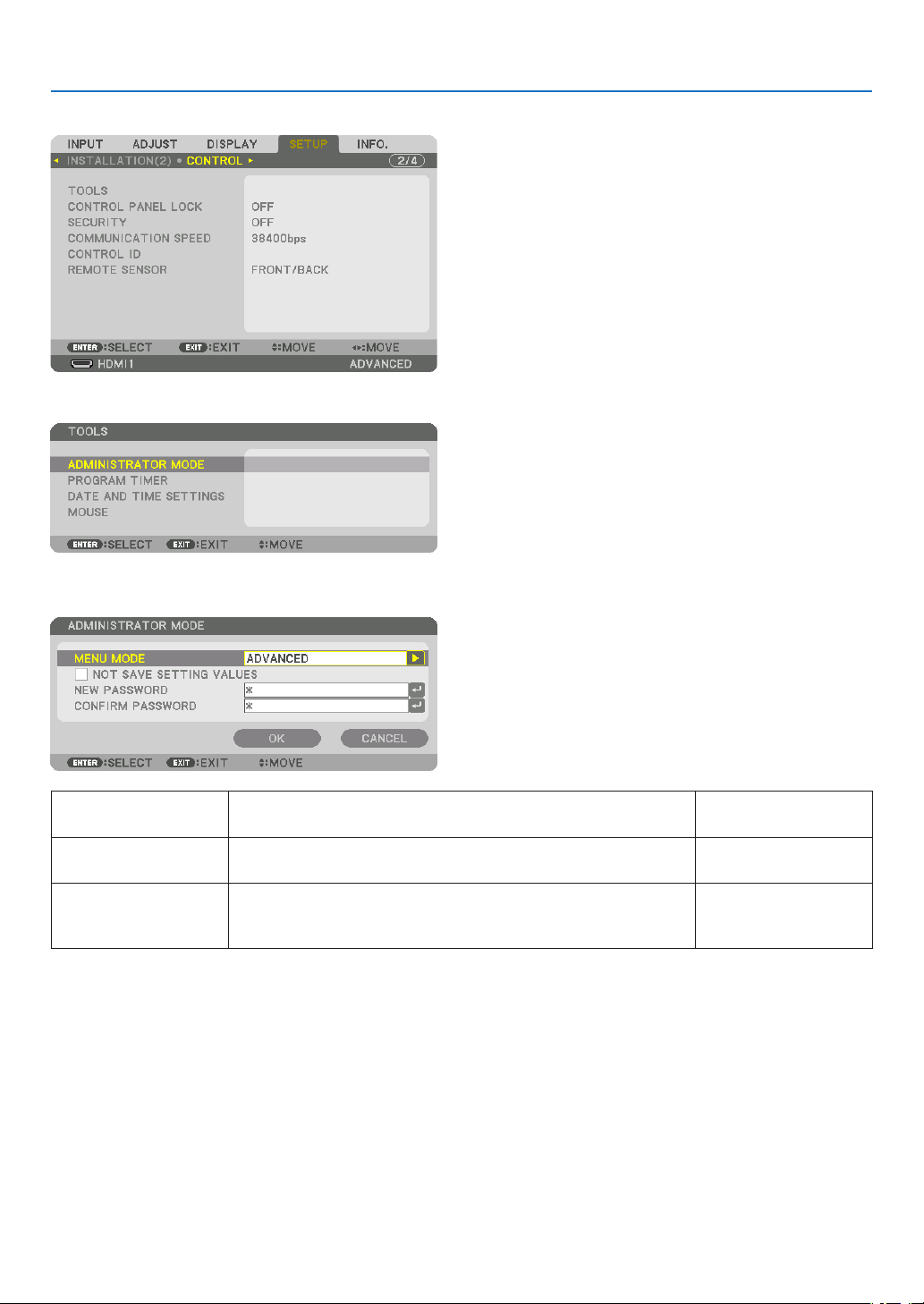
116
5. Using On-Screen Menu
[CONTROL]
TOOLS
ADMINISTRATORMODE
ThisallowsyoutoselectMENUMODE,savesettings,andsetapasswordfortheadministratormode.
MENUMODESelecteither[BASIC]or[ADVANCED]menu.
(→page
76)
—
NOTSAVESETTING
VALUES
Placingacheckmarkwillnotsaveyourprojectorsettings.
Clearthischeckboxtosaveyourprojectorsettings.
—
NEWPASSWORD/
CONFIRMPASS-
WORD
Assignapasswordfortheadministratormode.Up to 10 alphanumeric
characters
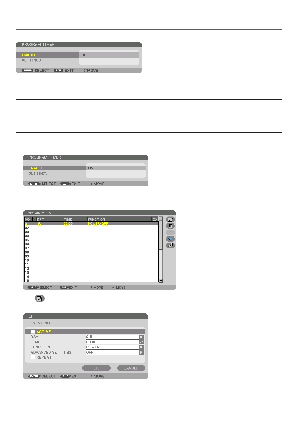
117
5. Using On-Screen Menu
PROGRAMTIMER
Thisoptionturnson/standbytheprojectorandchangesvideosignals,andselectsLIGHTmodeautomaticallyata
speciedtime.
NOTE:
•Beforeusing[PROGRAMTIMER],makesurethatthe[DATEANDTIME]featureisset.(→page120)
MakesurethattheprojectorisinthestandbyconditionwiththePOWERcordconnected.
Theprojectorhasabuilt-inclock.Theclockwillkeepworkingforaboutamonthafterthemainpoweristurnedoff.Ifthemain
powerisnotsuppliedtotheprojectorforamonthormore,itrequirestoset[DATEANDTIMESETTINGS]featureagain.
Setting a new program timer
1.OnthePROGRAMTIMERscreen,usethe▲ or ▼buttontoselect[SETTINGS]andpresstheENTERbutton.
The [PROGRAM LIST] screen will be displayed.
2.SelectablankprogramnumberandpresstheENTERbutton.
The [ (EDIT)] screen will be displayed.
3.Makesettingsforeachitemasrequired.
ACTIVE .................. Place a check mark to enable the program.
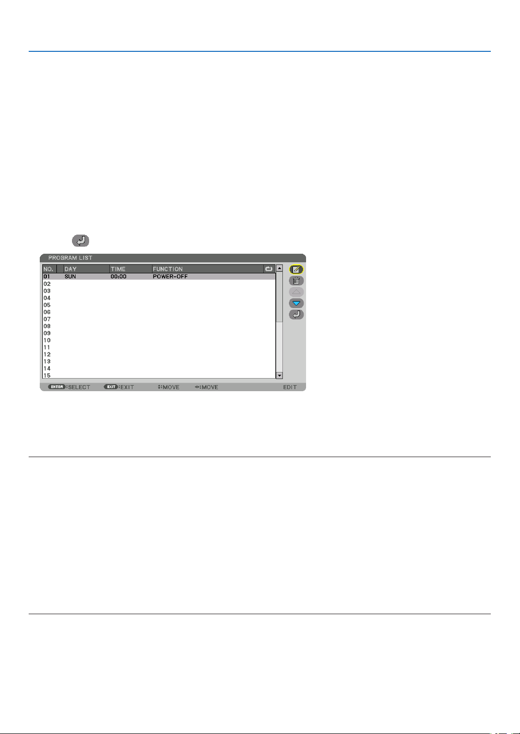
118
5. Using On-Screen Menu
DAY ........................ Select days of the week for the program timer. To execute the program from Monday to Friday, select [MON-
FRI]. To execute the program in everyday basis, select [EVERYDAY].
TIME ...................... Set the time to execute the program. Enter time in 24-hour format.
FUNCTION ............. Select a function to be executed. Selecting [POWER] will allow you to turn on or off the projector by setting
[ADVANCED SETTINGS]. Selecting [INPUT] will allow you to select an input terminal by setting [ADVANCED
SETTINGS]. Selecting [LIGHT MODE] will allow you to select one option among [NORMAL], [ECO1], [ECO2]
and [LONG LIFE] for [LIGHT MODE] by setting [ADVANCED SETTINGS].
ADVANCED SETTINGS
.............................. Select one option for the selected item in [FUNCTION].
REPEAT .................. Place a check mark to repeat the program continuing basis. To use the program this week only, clear the
check mark.
4.Select[OK]andpresstheENTERbutton.
This will complete the settings.
You will be returned to the [PROGRAM LIST] screen.
5.Select[
(BACK)]andpresstheENTERbutton.
You will be returned to the [PROGRAM TIMER] screen.
6.Select[EXIT]andpresstheENTERbutton.
You will be returned to the [TOOLS] screen.
NOTE:
•Upto30differenttimersettingscanbeprogrammed.
•TheProgramTimerisexecutedonasettimebasis,notinaprogrambasis.
•Oncetheprogramnotmarkedwithacheckin[REPEAT]hasbeenexecuted,thecheckmarkinthe[ACTIVE]checkboxwillbe
clearedautomaticallyandtheprogramwillbedisabled.
•Whentheon-timeandtheoff-timesetforthesametime,theoff-timesettingwilltakepreference.
•Whentwodifferentsourcesaresetforthesametime,thelargerprogramnumberwilltakepreference.
•Theon-timesettingwillnotbeexecutedwhilethecoolingfansarerunningoranerrorisoccurring.
•Iftheoff-timesettingisexpiredundertheconditioninwhichthepoweroffisnotpossible,theoff-timersettingwillnotbeexecuted
untilthepoweroffbecomespossible.
•Programsnotmarkedwithacheckmarkin[ACTIVE]ofthe[EDIT]screenwillnotbeexecutedeveniftheProgramTimeris
enabled.
•Whentheprojectoristurnedonbyusingtheprogramtimerandifyouwanttoturnofftheprojector,settheoff-timeordoit
manuallysoasnottoleavetheprojectoronforalongperiodoftime.

119
5. Using On-Screen Menu
Activating the program timer
1.Select[ENABLE]onthe[PROGRAMTIMER]screenandpresstheENTERbutton.
The selection screen will be displayed.
2.Pressthe▼buttontoalignthecursorwith[ON]andthenpresstheENTERbutton.
Return to the [PROGRAM TIMER] screen.
NOTE:
•Whentheeffectivesettingsofthe[PROGRAMTIMER]havenotbeensetto[ON],theprogramwillnotbeexecutedevenifthe
[ACTIVE]itemsintheprogramlisthavebeenticked.
•Evenwhentheeffectivesettingsofthe[PROGRAMTIMER]aresetto[ON],the[PROGRAMTIMER]willnotworkuntilthe[PRO-
GRAMTIMER]screenisclosed.
Editing the programmed settings
1.Onthe[PROGRAMLIST]screen,selectaprogramyouwanttoeditandpresstheENTERbutton.
2.Changethesettingsonthe[EDIT]screen.
3.Select[OK]andpresstheENTERbutton.
The programmed settings will be changed.
You will be returned to the [PROGRAM LIST] screen.
Changingtheorderofprograms
1.Onthe[PROGRAMLIST]screen,selectaprogramwhoseorderyouwanttochangeandpressthe▶button.
2.Pressthe▼buttontoselect▲ or ▼.
3.PresstheENTERbuttonafewtimestoselectarowtowhichyouwishtomovetheprogram.
The order of the programs will be changed.
Deleting the programs
1.Onthe[PROGRAMLIST]screen,selectaprogramnumberyouwanttodeleteandpressthe▶button.
2.Pressthe▼buttontoselect[
(DELETE)].
3.PresstheENTERbutton.
The confirmation screen will be displayed.
4.Select[YES]andpresstheENTERbutton.
The program will be deleted.
This will complete deleting the program.

120
5. Using On-Screen Menu
DATEANDTIMESETTINGS
Youcansetthecurrenttime,month,date,andyear.
NOTE:Theprojectorhasabuilt-inclock.Theclockwillkeepworkingforaboutamonthafterthemainpoweristurnedoff.Ifthe
mainpowerisoffforamonthormore,thebuilt-inclockwillcease.Ifthebuilt-inclockceases,setthedateandtimeagain.The
built-inclockwillnotceasewhileinthestandbymode.Inordertoactivatethebuilt-inclockcontinuouslyevenwhentheprojector
isnotused,leaveitinthestandbystatenotpluggingoffthepowercord.
TIME ZONE SETTINGS .............. Select your time zone.
DATE AND TIME SETTINGS ...... Set your current date (MM/DD/YYYY) and time (HH:MM).
INTERNET TIME SERVER: If you place a check mark, the projector’s built-in clock will be syn-
chronized with an Internet time server in every 24 hours and at the time of projector’s startup.
UPDATE: Synchronizes the projector’s built-in clock immediately. The UPDATE button is not
available unless the INTERNET TIME SERVER check box is turned on.
SUMMER TIME SETTINGS ....... If you place a check mark, the clock for daylight saving will be enabled.
[MOUSE]
ThisfunctionisforusingacommerciallyavailableUSBmouseviatheUSB-Aportonthisprojector.
BUTTON ................. Select for using the mouse either by right or left hand.
SENSITIVITY .......... Select the sensitivity of mouse among FAST, MIDDLE and LOW.
NOTE:ThissettingisnotguaranteedmotionofallcommerciallyavailableUSBmouses.
DisablingtheCabinetButtons[CONTROLPANELLOCK]
ThisoptionturnsonorofftheCONTROLPANELLOCKfunction.
NOTE:
•Howtocancelthe[CONTROLPANELLOCK]
Whenthe[CONTROLPANELLOCK]issetto[ON],presstheINPUTbuttononthemainbodyforabout10secondstocancelthe
[CONTROLPANELLOCK]setting.
TIP:
•Whenthe[CONTROLPANELLOCK]isturnedon,akeylockicon[
]willbedisplayedatthebottomrightofthemenu.
•ThisCONTROLPANELLOCKdoesnotaffecttheremotecontrolfunctions.
EnablingSecurity[SECURITY]
ThisfeatureturnsonorofftheSECURITYfunction.
Unlessthecorrectkeywordisentered,theprojectorcannotprojectanimage.(→page
41)
NOTE:Yoursettingwillnotbeaffectedevenwhen[RESET]isdonefromthemenu.
SelectingCommunicationSpeed[COMMUNICATIONSPEED]
ThisfeaturesetsthecommunicationspeedforthePCControlport(D-Sub9P).Makesuretosettheappropriate
speed for the device to connect.
NOTE:
•Yourselectedcommunicationspeedwillnotbeaffectedevenwhen[RESET]isdonefromthemenu.
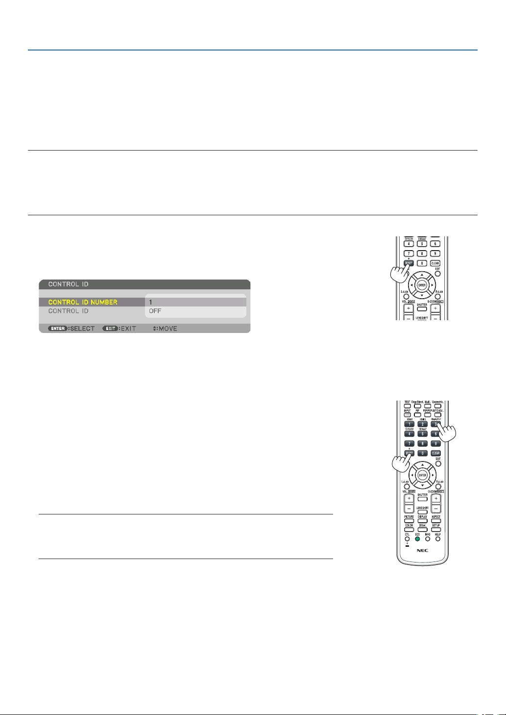
121
5. Using On-Screen Menu
SettingIDtotheProjector[CONTROLID]
YoucanoperatemultipleprojectorsseparatelyandindependentlywiththesingleremotecontrolthathastheCONTROL
IDfunction.IfyouassignthesameIDtoalltheprojectors,youcanconvenientlyoperatealltheprojectorstogether
usingthesingleremotecontrol.Todoso,youhavetoassignanIDnumbertoeachprojector.
CONTROL ID NUMBER ....... Select a number from 1 to 254 you wish to assign to your projector.
CONTROL ID .......................Select [OFF] to turn off the CONTROL ID setting and select [ON] to turn on the CONTROL ID setting.
NOTE:
•When[ON]isselectedfor[CONTROLID],theprojectorcannotbeoperatedbyusingtheremotecontrolthatdoesnotsupport
theCONTROLIDfunction.(Inthiscasethebuttonsontheprojectorcabinetcanbeused.)
•Yoursettingwillnotbeaffectedevenwhen[RESET]isdonefromthemenu.
•PressingandholdingtheENTERbuttonontheprojectorcabinetfor10secondswilldisplaythemenuforcancelingtheControl
ID.
Assigning or Changing the Control ID
1.Turnontheprojector.
2.PresstheIDSETbuttonontheremotecontrol.
The CONTROL ID screen will be displayed.
If the projector can be operated with the current remote control ID, the [AC-
TIVE] will be displayed. If the projector cannot be operated with the current
remote control ID, the [INACTIVE] will be displayed. To operate the inactive
projector, assign the control ID used for the projector by using the following
procedure (Step 3).
3.PressoneofnumerickeypadbuttonswhilepressingandholdingtheID
SETbuttonontheremotecontrol.
Example:
To assign “3”, press the “3” button on the remote control.
No ID means that all the projectors can be operated together with a single
remote control. To set “No ID”, enter “000” or press the CLEAR button.
TIP:TherangeofIDsisfrom1to254.
4.ReleasetheIDSETbutton.
The updated CONTROL ID screen will be displayed.
NOTE:
•TheIDscanbeclearedinafewdaysafterthebatteriesarerundownorremoved.
•Accidentallypressinganyoneofthebuttonsoftheremotecontrolwillclearcurrently
speciedIDwithbatteriesremoved.

122
5. Using On-Screen Menu
TurningOnorOffRemoteSensor[REMOTESENSOR]
Thisoptiondetermineswhichremotesensorontheprojectorisenabledinwirelessmode.
Theoptionsare:FRONT/BACK,FRONT,BACK,andHDBaseT*.
NOTE:
•TheremotecontroloftheprojectorwillnotbeabletoreceivesignalsifthepowersupplyoftheHDBaseTtransmissiondevice
connectedtotheprojectorisswitchedonwhenthishasbeensetto“HDBaseT”.
TIP:
•Iftheremotecontrolsystemdoesnotfunctionwhendirectsunlightorstrongilluminationstrikestheremotecontrolsensorof
theprojector,changetootheroption.

123
5. Using On-Screen Menu
[NETWORK SETTINGS]
Important:
•Consultwithyournetworkadministratoraboutthesesettings.
•WhenusingawiredLAN,connecttheEthernetcable(LANcable)totheLANportontheprojector.(→page150)
•Pleaseuseashieldedtwistedpair(STP)cableofCategory5eorhigherfortheLANcable(soldcommercially).
TIP:Thenetworksettingsyoumakewillnotbeaffectedevenwhen[RESET]isdonefromthemenu.
Hints on How to Set Up LAN Connection
TosetuptheprojectorforaLANconnection:
Select[WIREDLAN]→[PROFILES]→[PROFILE1]or[PROFILE2].
TwosettingscanbesetforwiredLAN.
Nextturnonorofffor[DHCP],[IPADDRESS],[SUBNETMASK],and[GATEWAY]andselect[OK]andpressthe
ENTERbutton.(→page124)
To recall LAN settings stored in the prole number:
Select[PROFILE1]or[PROFILE2]forwiredLAN,andthenselect[OK]andpresstheENTERbutton.(→page124)
To connect a DHCP server:
Turnon[DHCP]forwiredLAN.Select[ON]andpresstheENTERbutton.TospecifyIPaddresswithoutusingthe
DHCPserver,turnoff[DHCP].(→page124)
To receive error messages via e-mail:
Select[ALERTMAIL],andset[SENDER'SADDRESS],[SMTPSERVERNAME],and[RECIPIENT'SADDRESS].
Last,select[OK]andpresstheENTERbutton.(→page126)

124
5. Using On-Screen Menu
WIRED LAN
INTERFACESelect[LAN]forusingtheLANportforconnectingtothewired
LAN.Select[HDBaseT]forusingtheHDBaseTIN/Ethernetport
forconnectingtothewiredLAN.Thecontrolfromtheconnected
devicewillbedisabledifnosignalissentandreceivedforthree
minutesiftheprojectorisconnectedtowiredLANthrutheHD-
BaseTIN/Ethernet.Forrefusingthis,setthestandbymodeto
[SLEEP]inadvance.
—
PROFILES
•ThesettingsforthewiredLANcanberecordedintheprojector
memory in two ways.
•Select[PROFILE1]or[PROFILE2]andthendosettingsfor
[DHCP]andtheotheroptions.
Afterdoingthis,select[OK]andpresstheENTERbutton.This
willstoreyoursettingsinmemory.
•Torecallthesettingsfrommemory:
Afterselecting[PROFILE1]or[PROFILE2]fromthe[PRO-
FILES]list.
Select[OK]andpresstheENTERbutton.
•Select[DISABLE]whennotconnectingtoawiredLAN
—
DHCP
PlaceacheckmarktoautomaticallyassignanIPaddresstothe
projectorfromyourDHCPserver.
ClearthischeckboxtoregistertheIPaddressorsubnetmask
numberobtainedfromyournetworkadministrator.
—
IPADDRESSSetyourIPaddressofthenetworkconnectedtotheprojector
when[DHCP]isturnedoff.
Up to 12 numeric
characters
SUBNETMASKSetyoursubnetmasknumberofthenetworkconnectedtothe
projectorwhen[DHCP]isturnedoff.
Up to 12 numeric
characters
GATEWAY
Setthedefaultgatewayofthenetworkconnectedtotheprojector
when[DHCP]isturnedoff.
Up to 12 numeric
characters
AUTODNSPlaceacheckmarktoautomaticallyassigntheIPaddressofyour
DNSserverconnectedtotheprojectorfromyourDHCPserver.
ClearthischeckboxtosettheIPaddressofyourDNSserver
connected to the projector.
Up to 12 numeric
characters
DNSCONFIGURA-
TION
SettheIPaddressofyourDNSserveronthenetworkconnected
totheprojectorwhen[AUTODNS]iscleared.
Up to 12 numeric
characters
RECONNECT
Retrytoconnecttheprojectortoanetwork.Trythisifyouhave
changed[PROFILES].
—
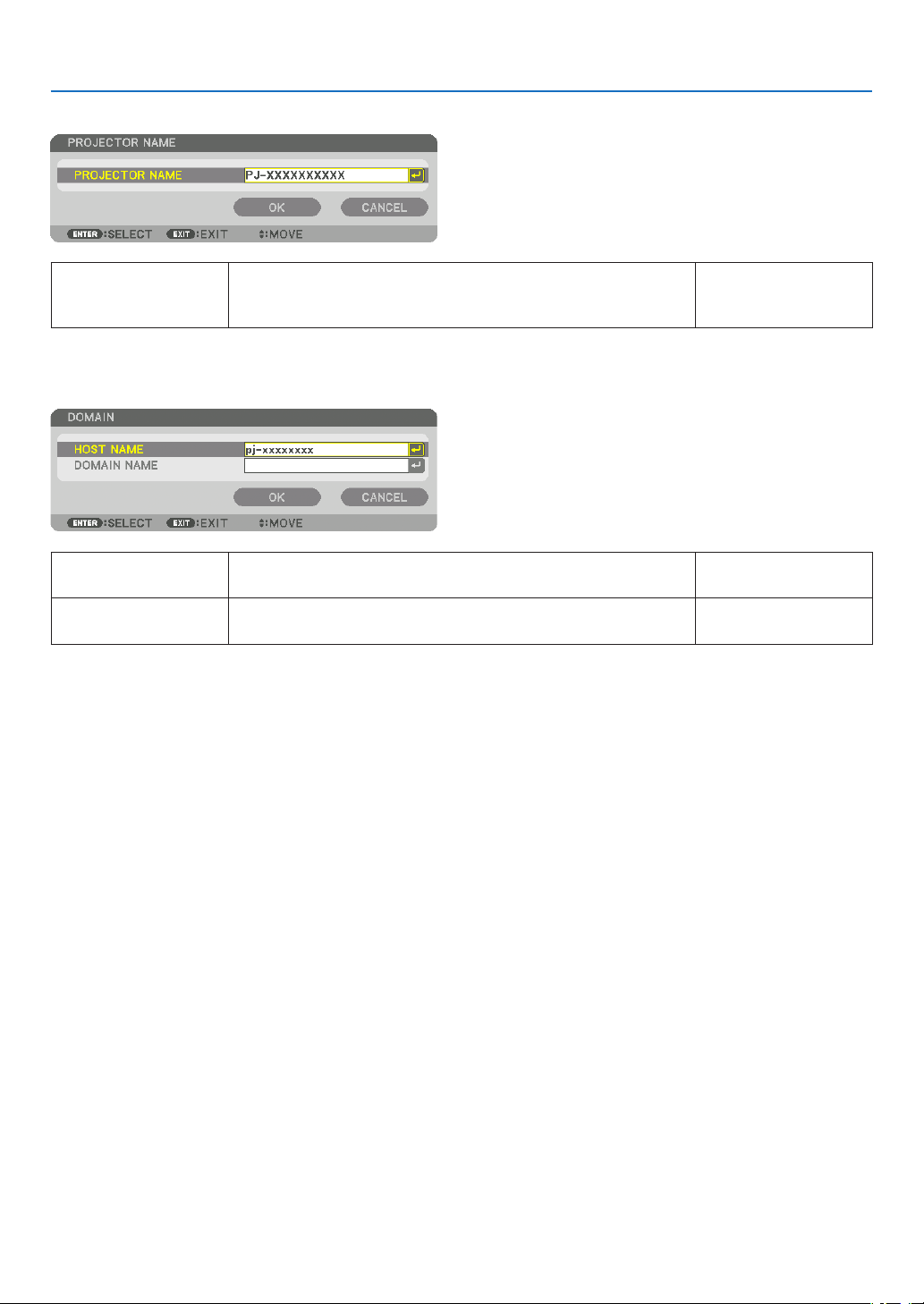
125
5. Using On-Screen Menu
PROJECTORNAME
PROJECTORNAMESetauniqueprojectorname.Up to 16 alphanu-
meric characters and
symbols
DOMAIN
Setahostnameanddomainnameoftheprojector.
HOSTNAMESetahostnameoftheprojector.Up to 16 alphanumeric
characters
DOMAINNAMESetadomainnameoftheprojector.Up to 60 alphanumeric
characters
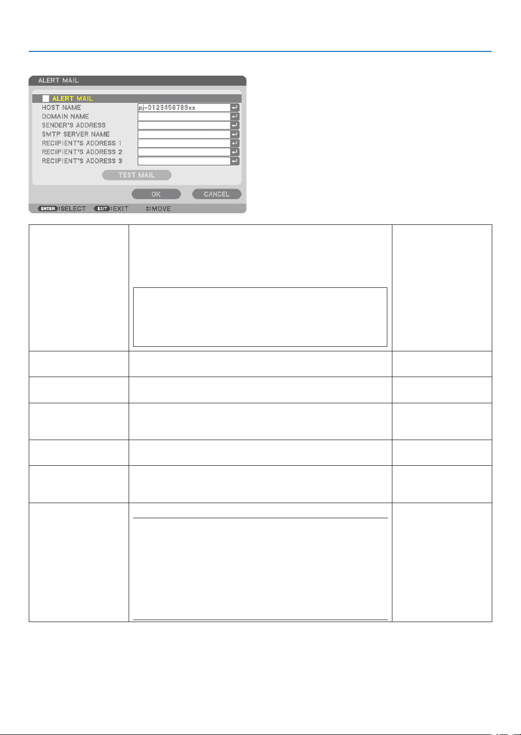
126
5. Using On-Screen Menu
ALERTMAIL
ALERTMAILThisoptionwillnotifyyourcomputeroferrormessagesviae-mail
whenusingwirelessorwiredLAN.
Placing a checkmark will turn on the Alert Mail feature.
Clearing a checkmark will turn off the Alert Mail feature.
Sampleofamessagetobesentfromtheprojector:
Subject:[Projector]ProjectorInformation
THECOOLINGFANHASSTOPPED.
[INFORMATION]
PROJECTORNAME:xxxxx
LIGHTHOURSUSED:xxxx[H]
—
HOSTNAMETypeinahostname.Up to 16 alphanumeric
characters
DOMAINNAMETypeinadomainnameofthenetworkconnectedtotheprojector.Up to 60 alphanumeric
characters
SENDER'SAD-
DRESS
Specifythesender’saddress.Up to 60 alphanu-
meric characters and
symbols
SMTPSERVER
NAME
TypeintheSMTPservernametobeconnectedtotheprojector.Up to 60 alphanumeric
characters
RECIPIENT'SAD-
DRESS1,2,3
Typeinyourrecipient’saddress.Up to 60 alphanu-
meric characters and
symbols
TESTMAIL
Sendatestmailtocheckifyoursettingsarecorrect.
NOTE:
•Ifyouenteredanincorrectaddressinatest,youmaynotreceivean
Alertmail.Shouldthishappen,checkiftheRecipient’sAddressis
correctlyset.
•Unlessanyoneofthe[SENDER'SADDRESS],[SMTPSERVER'S
NAME]or[RECIPIENT'SADDRESS1-3]isselected,[TESTMAIL]is
notavailable.
•Besuretohighlight[OK]andpresstheENTERbuttonbeforeexecuting
[TESTMAIL].
—

127
5. Using On-Screen Menu
NETWORKSERVICE
HTTPSERVERSetapasswordforyourHTTPserver.Up to 10 alphanumeric
characters
PJLink
Thisoptionallowsyoutosetapasswordwhenyouusethe
PJLinkfeature.
NOTE:
•Donotforgetyourpassword.However,ifyouforgetyourpassword,
consultwithyourdealer.
•WhatisPJLink?
PJLinkisastandardizationofprotocolusedforcontrollingprojectors
ofdifferentmanufacturers.Thisstandardprotocolisestablishedby
JapanBusinessMachineandInformationSystemIndustriesAssocia-
tion(JBMIA)in2005.
TheprojectorsupportsallthecommandsofPJLinkClass1.
•SettingofPJLinkwillnotbeaffectedevenwhen[RESET]isdonefrom
themenu.
Up to 32 alphanumeric
characters
AMXBEACONTurnonorofffordetectionfromAMXDeviceDiscoverywhen
connectingtothenetworksupportedbyAMX’sNetLinxcontrol
system.
TIP:
WhenusingadevicethatsupportsAMXDeviceDiscovery,allAMXNetLinx
controlsystemwillrecognizethedeviceanddownloadtheappropriate
DeviceDiscoveryModulefromanAMXserver.
Placing a checkmark will enable detecting the projector from AMX Device
Discovery.
Clearing a checkmark will disable detecting the projector from AMX
Device Discovery.
—
CRESTRON
ROOMVIEW:Turnonoroffwhencontrollingtheprojectorfrom
yourPC.
CRESTRONCONTROL:Turnonoroffwhencontrollingthe
projector from your controller.
•CONTROLLERIPADDRESS:EnteryourIPaddressofCREST-
RONSERVER.
•IPID:EnteryourIPIDofCRESTRONSERVER.
Up to 12 numeric
characters
ExtronXTPSetforconnectingthisprojectortotheExtronXTPtransmitter.ON
willenabletoconnectwiththeXTPtransmitter.OFFwilldisable
toconnectwiththeXTPtransmitter.
—
TIP:TheCRESTRONsettingsarerequiredonlyforusewithCRESTRONROOMVIEW.
Formoreinformation,visit
http://www.crestron.com

128
5. Using On-Screen Menu
[SOURCE OPTIONS]
SettingAutoAdjust[AUTOADJUST]
ThisfeaturesetstheAutoAdjustmodesothatthecomputersignalcanbeautomaticallyormanuallyadjustedfor
noiseandstability.Youcanautomaticallymakeadjustmentintwoways:[NORMAL]and[FINE].
OFF ........................ The computer signal will not be automatically adjusted. You can manually optimize the computer signal.
NORMAL ................ Default setting. The computer signal will be automatically adjusted. Normally select this option.
FINE ....................... Select this option if fine adjustment is needed. It takes more time to switch to the source than when [NOR-
MAL]is selected.
TIP:
•Thedefaultsettingwhenshippedfromthefactoryis[NORMAL].
•WhentheAUTOADJ.buttonispressed,thesame[FINE]adjustmentiscarriedout.
[AUDIOSELECT]
ThisselectstheaudioinputoftheHDMI1INterminal,HDMI2INterminal,DisplayPortINterminalandHDBaseT
IN/Ethernetport.
SelectingDefaultSource[DEFAULTINPUTSELECT]
Youcansettheprojectortodefaulttoanyoneofitsinputseachtimetheprojectoristurnedon.
LAST ...................... Sets the projector to default to the previous or last active input each time the projector is turned on.
AUTO ..................... Searches for an active source in order of HDMI1 → HDMI2 → DisplayPort → COMPUTER → HDBaseT and
displays the first found source.
HDMI1 ................... Displays the digital source from the HDMI 1 IN connector every time the projector is turned on.
HDMI2 ................... Displays the digital source from the HDMI 2 IN connector every time the projector is turned on.
DisplayPort ............ Displays the digital source from the DisplayPort every time the projector is turned on.
COMPUTER ........... Displays the computer signal from the COMPUTER IN connector every time the projector is turned on.
HDBaseT ................ Project the HDBaseT signal.
[SEAMLESSSWITCHING]
Whentheinputconnectorisswitched,theimagedisplayedbeforeswitchingisheldtoswitchtothenewimagewithout
abreakduetoabsenceofasignal.
SelectingaColororLogoforBackground[BACKGROUND]
Usethisfeaturetodisplayablue/blackscreenorlogowhennosignalisavailable.Thedefaultbackgroundis[BLUE].
NOTE:
•Evenwhenthebackgroundlogoisselected,iftwopicturesaredisplayedin[PIP/PICTUREBYPICTURE]mode,thebluebackground
isdisplayedwithoutthelogowhenthereisnosignal.

129
5. Using On-Screen Menu
[HDBaseTOUTSELECT]
SelectsignaltooutputfromtheHDBaseTOUT/Ethernetportontheprojector.Whentwoimagesareprojectedsimul-
taneously(PIP/PICTUREBYPICTURE),theimageforthemainscreenisoutput.
AUTO ..................... Output the input signal. When [PIP] has been set, the input signal for the main screen is output.
HDMI1 ................... Output the input signal thru the HDMI 1 IN terminal.
HDMI2 ................... Output the input signal thru the HDMI 2 IN terminal.
DisplayPort ............ Output the input signal thru the DisplayPort IN terminal.
HDBaseT ................ Output the input signal thru the HDBaseT IN/Ethernet port.
NOTE:
•SignalthrutheCOMPUTERINterminalcannotbeoutput.Inthestate[PIP]or[PICTUREBYPICTURE]hasbeensetand[AUTO]
hasbeensetforthisfunction,moreover,theinputterminalforthemainscreenistheCOMPUTERandtheinputterminalforthe
subscreenisoneamongtheHDMI1IN,HDMI2IN,DisplayPortINterminals,orHDBaseTIN/Ethernetport,thesignalfromthe
subscreenwillbeoutput.
•Ifthesetinputterminalsformainandsubscreenfor[PIP]and[PICTUREBYPICTURE]aredifferedfromtheselectedinput
terminals,anyimagewillbeoutput.
•4K60pand4K50psignalscannotbeoutput.
[EDIDVERSION]
SwitchtheEDIDversionfortheHDMI1INandHDMI2INterminals.
MODE1 .................. Supports general signal
MODE2 .................. Supports 4K signal
Select this mode for displaying 4K image using the device supporting 4K
NOTE:
Ifimageandsoundcannotbeoutputin[MODE2],switchto[MODE1].
[HDCPVERSION]
SwitchtheHDCPversionfortheHDMI1IN,HDMI2INandHDBaseTIN/Ethernetterminals.
HDCP2.2 ................ Automatically switch the mode HDCP2.2 and HDCP1.4
HDCP1.4 ................ Forcedly perform transmission with HDCP1.4
NOTE:
•IfimageandsoundcannotbeoutputfromthemonitorconnectedwiththeHDBaseTOUT/Ethernetport,switchtheHDCPversion
toHDCP1.4.

130
5. Using On-Screen Menu
[POWER OPTIONS]
[STANDBYMODE]
Selectthestandbymode:
NORMAL ................ Automatically transit the standby state and control consumption power based on the projector setting and
the state of the connected device. (→ page
168)
SLEEP .................... Maintain the state of sleep. Consumption power becomes higher than the setting of NORMAL. Select this
mode in the following cases:
•ForusingtheHDBaseTIN/EthernetandHDBaseTOUT/Ethernetportsconstantly.
•ForusingtheUSB-Aportconstantly.
[EXAMPLE]
- For connecting plural numbers of projector in a daisy chain. (→ page
147)
- For connecting to a HDBaseT transmission device (→ page
146)
TIP:
•The[STANDBYMODE]settingisnotchangedby[RESET].
•ConsumptionpowerintheSTANDBYMODEisexcludedfromthecalculationforcarbonsaving.
EnablingDirectPowerOn[DIRECTPOWERON]
Turnstheprojectoronautomaticallywhenthepowercordisinsertedintoanactivepoweroutlet.Thiseliminatesthe
needtoalwaysusethePOWERbuttonontheremotecontrolorprojectorcabinet.
TurningOntheProjectorbyDetectingInputSignal[AUTOPOWERONSELECT]
Underthestateofstandbyorsleep,theprojectorautomaticallydetectsandprojectssynchronizingsignalinputfrom
theselectedterminalsamongComputer,HDMI1/2,DisplayPort,andHDBaseTbythisfunction.
OFF ........................ AUTO POWER ON SELECT function becomes inactive.
HDMI1, HDMI2, DisplayPort, COMPUTER, HDBaseT*
.............................. When the projector detects the computer signal input from the selected terminal, automatically it will be
turned ON and will project the computer screen.
NOTE:
•IfyouwanttoactivatethisAUTOPOWERONSELECTfunctionafterpoweringOFFtheprojector,interruptsignalfrominput
terminalsorpulloutthecomputercablefromtheprojectorandwaitforover3secondsandtheninputsignalfromtheselected
terminal.Incasecomputersignaliscontinuouslyinputtotheprojector,howevertheprojectoristurnedOFFandisinthetransition
toSLEEPmode,itwillkeepSLEEPmodeandwillnotbeturnedONautomatically.Inaddition,ifsignalfromHDMI1/2,DisplayPort
orHDBaseTiscontinuouslyinputtotheprojector,theprojectormaybeturnedONagainautomaticallybasedonthesettingof
externaldeviceseveniftheprojectoristurnedOFFandintheconditionofSLEEPmode.
•Thisfunctionisnotactivatedeitherbycomponentsignalinputfromthecomputerscreeninputterminalorcomputersignalas
SynconGreenandCompositeSync.

131
5. Using On-Screen Menu
EnablingPowerManagement[AUTOPOWEROFF]
Whenthisoptionisselectedyoucanenabletheprojectortoautomaticallyturnoff(attheselectedtime:0:05,0:10,
0:15,0:20,0:30,1:00)ifthereisnosignalreceivedbyanyinputorifnooperationisperformed.
UsingOffTimer[OFFTIMER]
1.Selectyourdesiredtimebetween30minutesand16hours:OFF,0:30,1:00,2:00,4:00,8:00,12:00,16:00.
2.PresstheENTERbuttonontheremotecontrol.
3.TheremainingtimestartscountingdownanditisdisplayedatthebottomoftheOn-ScreenMenu.
4.Theprojectorwillturnoffafterthecountdowniscomplete.
NOTE:
•Tocancelthepresettime,set[OFF]forthepresettimeorturnoffthepower.
•Whentheremainingtimereaches3minutesbeforetheprojectoristurnedoff,the[THEPROJECTORWILLTURNOFFWITHIN3
MINUTES]messagewillbedisplayedonthebottomofthescreen.

132
5. Using On-Screen Menu
Returning to Factory Default [RESET]
TheRESETfeatureallowsyoutochangeadjustmentsandsettingstothefactorypresetfora(all)source(s)except
thefollowing:
[CURRENTSIGNAL]
Resetstheadjustmentsforthecurrentsignaltothefactorypresetlevels.
Theitemsthatcanberesetare:[PRESET],[CONTRAST],[BRIGHTNESS],[COLOR],[HUE],[SHARPNESS],[AS-
PECTRATIO],[HORIZONTAL],[VERTICAL],[CLOCK],[PHASE],and[OVERSCAN].
[ALLDATA]
Resetalltheadjustmentsandsettingsforallthesignalstothefactorypreset.
All items can be reset EXCEPT[ENTRYLIST],[LANGUAGE],[BACKGROUND],[EDGEBLENDING],[MULTI
SCREEN],[SCREENTYPE],[GEOMETRICCORRECTION],[REF.WHITEBALANCE],[STATICCONVERGENCE],
[ADMINISTRATORMODE],[CONTROLPANELLOCK],[SECURITY],[COMMUNICATIONSPEED],[DATEAND
TIMESETTINGS],[CONTROLID],[STANDBYMODE],[FANMODE],[REF.LENSMEMORY],[EDIDVERSION],
[HDCPVERSION],[LIGHTHOURSUSED],[TOTALCARBONSAVINGS],[WIREDLAN].
[ALLDATA(INCLUDINGENTRYLIST)]
Resetalltheadjustmentsandsettingsforallthesignalsincludingthe[ENTRYLIST]tothefactorypresetexcept
[LANGUAGE],[BACKGROUND],[EDGEBLENDING],[MULTISCREEN],[SCREENTYPE],[GEOMETRICCOR-
RECTION],[REF.WHITEBALANCE],[STATICCONVERGENCE],[ADMINISTRATORMODE],[CONTROLPANEL
LOCK],[SECURITY],[COMMUNICATIONSPEED],[DATEANDTIMESETTINGS],[CONTROLID],[STANDBY
MODE],[FANMODE],[REF.LENSMEMORY],[EDIDVERSION],[HDCPVERSION],[LIGHTHOURSUSED],[TO-
TALCARBONSAVINGS],[WIREDLAN].
Alsodeletesallthesignalsinthe[ENTRYLIST]andreturnstothefactorypreset.
NOTE:LockedsignalsinEntryListcannotbereset.
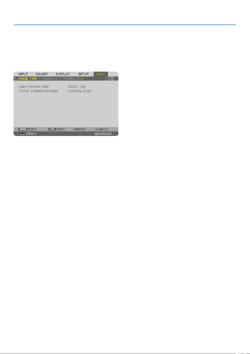
133
5. Using On-Screen Menu
❽ Menu Descriptions & Functions [INFO.]
Displaysthestatusofthecurrentsignalandlightmoduleusage.Thisitemhastenpages.Theinformationincluded
is as follows:
TIP:PressingtheHELPbuttonontheremotecontrolwillshowthe[INFO.]menuitems.
[USAGE TIME]
[LIGHTHOURSUSED](H)
[TOTALCARBONSAVINGS](kg-CO2)
•[TOTALCARBONSAVINGS]
Thisdisplaystheestimatedcarbonsavinginformationinkg.Thecarbonfootprintfactorinthecarbonsavingcal-
culationisbasedontheOECD(2008Edition).(→page
35)
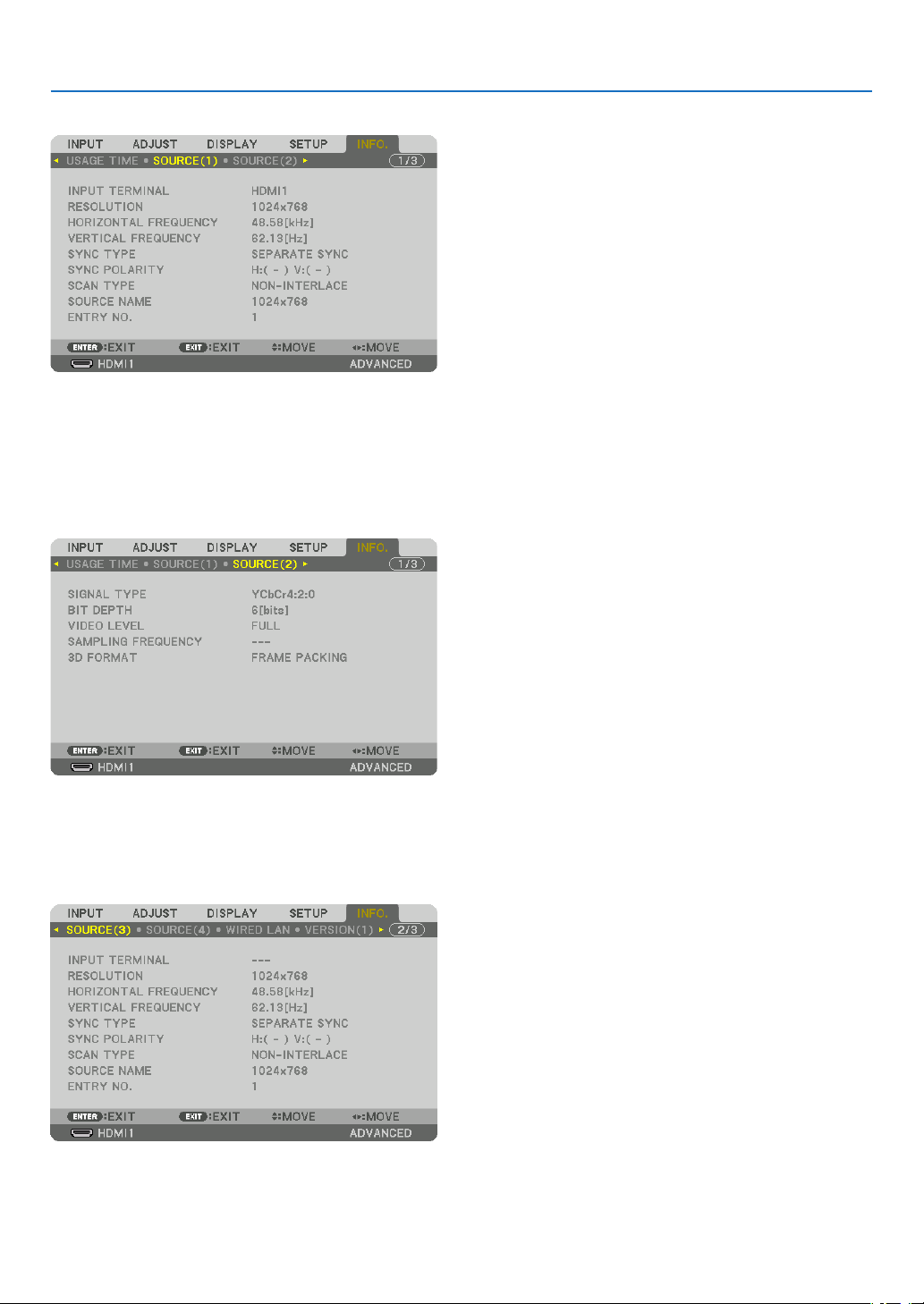
134
5. Using On-Screen Menu
[SOURCE(1)]
INPUTTERMINALRESOLUTION
HORIZONTALFREQUENCYVERTICALFREQUENCY
SYNCTYPESYNCPOLARITY
SCANTYPESOURCENAME
ENTRYNO.
[SOURCE(2)]
SIGNALTYPEBITDEPTH
VIDEOLEVELSAMPLINGFREQUENCY
3DFORMAT
[SOURCE(3)]
INPUTTERMINALRESOLUTION
HORIZONTALFREQUENCYVERTICALFREQUENCY
SYNCTYPESYNCPOLARITY
SCANTYPESOURCENAME
ENTRYNO.
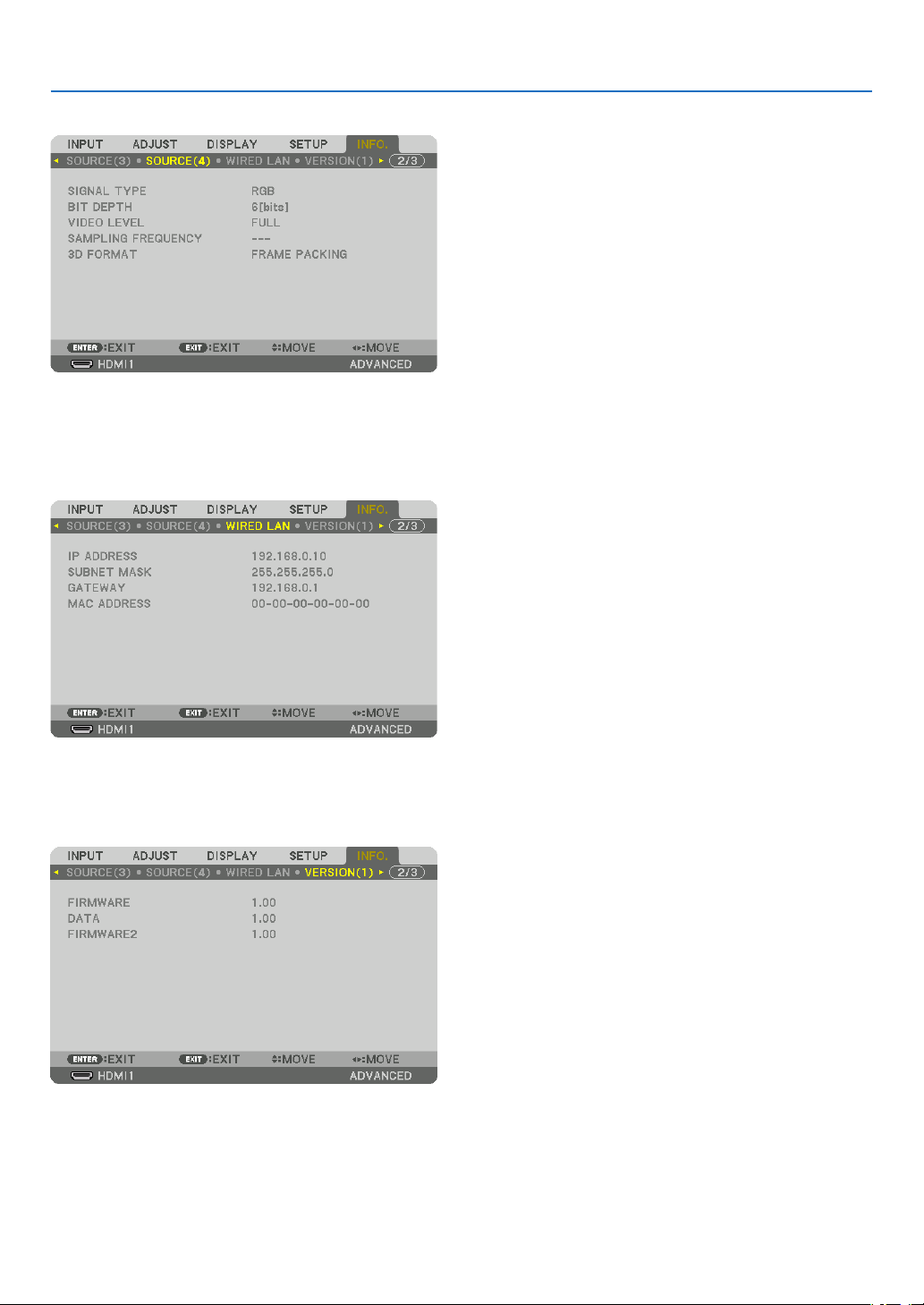
135
5. Using On-Screen Menu
[SOURCE(4)]
SIGNALTYPEBITDEPTH
VIDEOLEVELSAMPLINGFREQUENCY
3DFORMAT
[WIRED LAN]
IPADDRESSSUBNETMASK
GATEWAYMACADDRESS
[VERSION(1)]
FIRMWAREDATA
FIRMWARE2
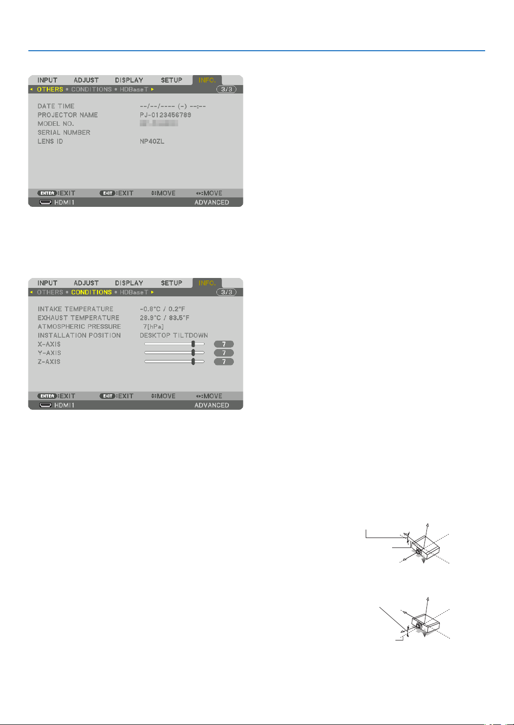
136
5. Using On-Screen Menu
[OTHERS]
DATETIMEPROJECTORNAME
MODELNO.SERIALNUMBER
LENSID
[CONDITIONS]
INTAKETEMPERATUREEXHAUSTTEMPERATURE
ATMOSPHERICPRESSUREINSTALLATIONPOSITION
X-AXISY-AXIS
Z-AXIS
AbouttheX-AXIS,Y-AXISandZ-AXISCONDITIONS
*ArrowdirectionoftheZ-AXISinthegurerepresentsthetopoftheprojector.
X-AXIS ................... Display the projector image at an angle of −100 – +100
degrees to the horizontal in the X-axis direction.
X-AXIS value of
the projector
Horizontal plane
X-axis
Gravity direction
Y-AXIS ................... Display the projector image at an angle of −100 – +100
degrees to the horizontal in the Y-axis direction.
Y-AXIS value of
the projector
Horizontal plane
Y-axis
Gravity direction
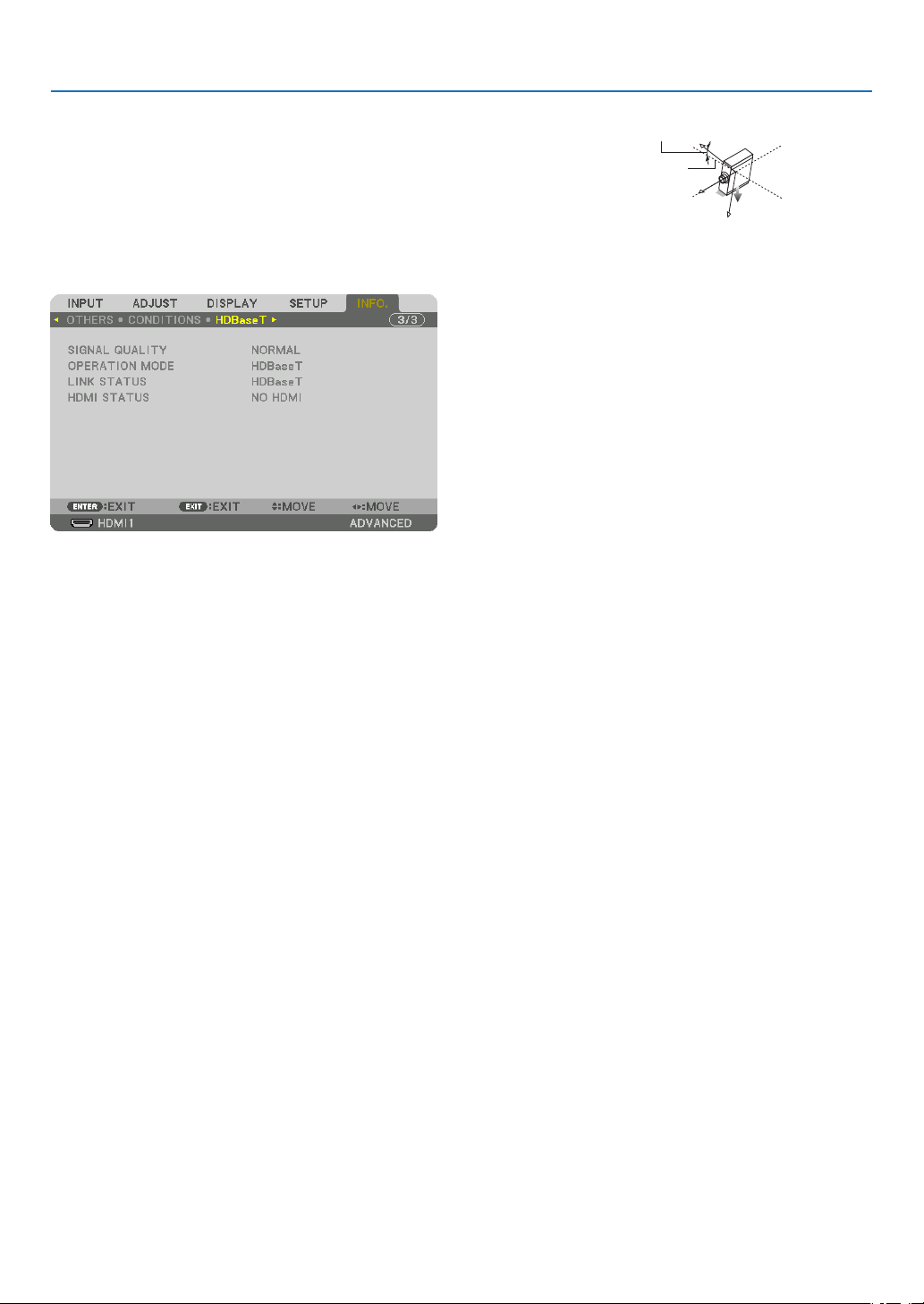
137
5. Using On-Screen Menu
Z-AXIS ................... Display the projector image at an angle of −100 – +100
degrees to the vertical in the Z-axis direction.
Z-AXIS value of
the projector
Horizontal
plane Z-axis
Gravity direction
[HDBaseT]
SIGNALQUALITYOPERATIONMODE
LINKSTATUSHDMISTATUS
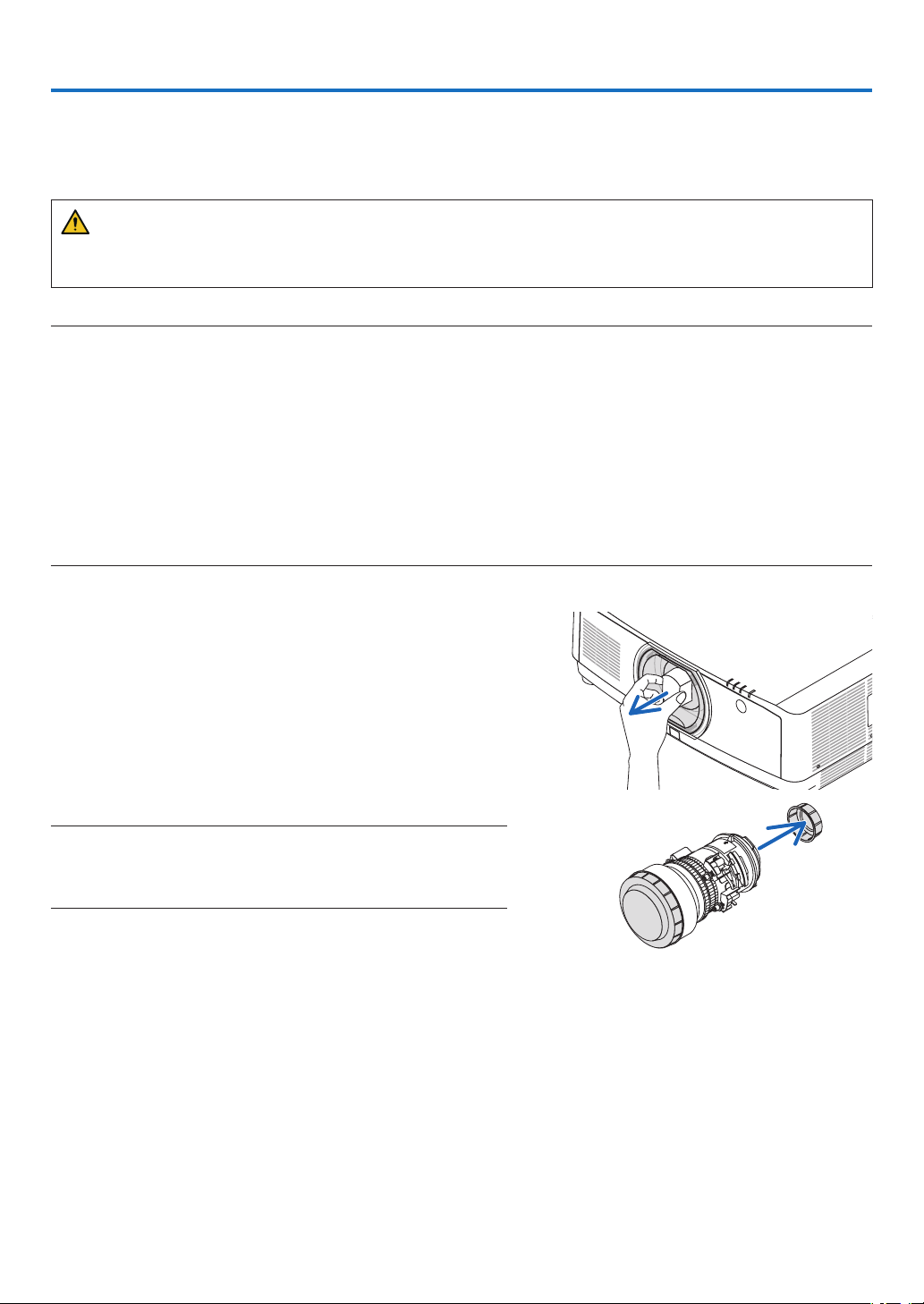
138
❶ Mounting a lens (sold separately)
Threeseparatebayonetstylelensescanbeusedwiththisprojector.ThedescriptionsherearefortheNP41ZLlens.
Mount other lenses in the same manner.
WARNING:
(1)Turnoffthepowerandwaitforthecoolingfantostop,(2)disconnectthepowercordandwaitfortheunitto
coolbeforemountingorremovingthelens.Failuretodosocanresultineyeinjury,electricshock,orburninjuries.
Important:
•Besuretocarryout[LENSCALIBRATION]afterreplacingthelens.
•Theprojectorandlensesaremadeofprecisionparts.Donotsubjectthemtoshockorexcessiveforces.
•Removetheseparatelysoldlenswhenmovingtheprojector.Ifnot,thelenscouldbesubjecttoshockwhiletheprojectorisbeing
moved,damagingthelensandthelensshiftmechanism.
•Whendismountingthelensfromtheprojector,returnthelenspositiontothehomepositionbeforeturningoffthepower.Failure
todosomaypreventthelensfrombeingmountedordismountedbecauseofnarrowspacebetweentheprojectorandthelens.
•Nevertouchthelenssurfacewhiletheprojectorisoperating.
•Beverycarefulnottoletdirt,grease,etc.,onthelenssurfaceandnottoscratchthelenssurface.
•Performtheseoperationsonaatsurfaceoverapieceofcloth,etc.,topreventthelensfromgettingscratched.
•Whenleavingthelensofftheprojectorforlongperiodsoftime,mountthedustcapontheprojectortopreventdustordirtfrom
gettinginside.
Mounting the lens
1.Removethedustcapfromtheprojector.
2.Removethelenscaponthebackofthelens.
NOTE:
•Makesuretoremovethelenscapattheunitbackside.Ifthelensunit
withthelenscapremainingonisinstalledontheprojector,itmaycause
ofmalfunction.
6. Connecting to Other Equipment
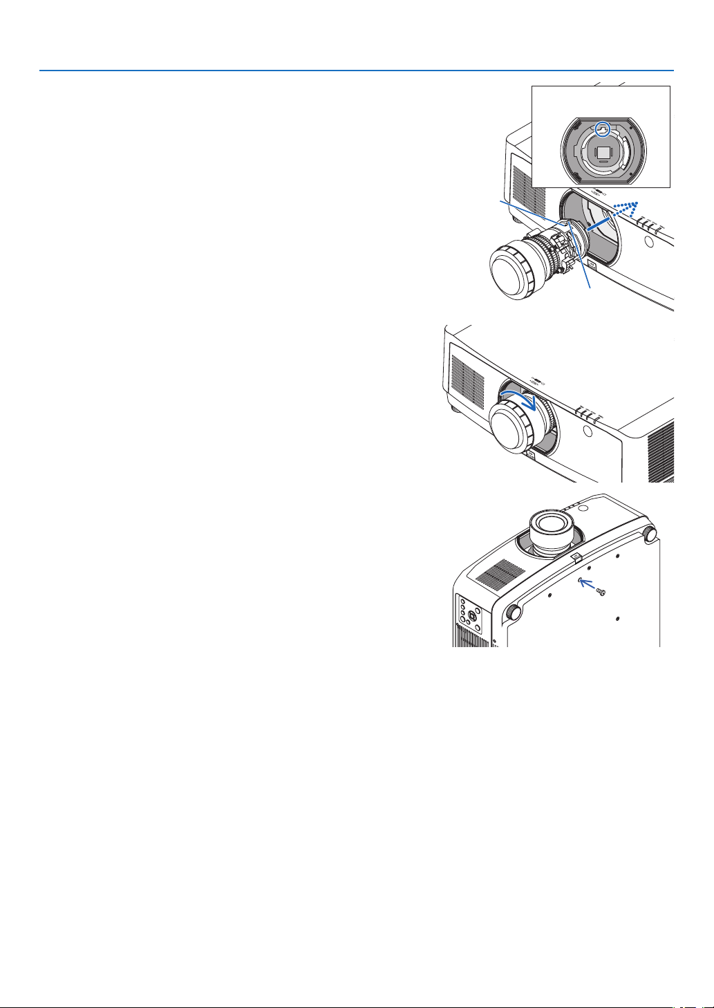
139
6. Connecting to Other Equipment
3.Insertthelensontotheprojectorfacingthearrowonthe
lens-labelupward.
Insert the lens slowly all the way in.
Guiding notch
Protrusion
Arrow
4.Turnthelensclockwise.
Turn until a click is heard.
The lens is now fastened onto the projector.
TIP:Mountingthelenstheftpreventionscrew
Fastenthelenstheftpreventionscrewincludedwiththeprojectortothe
bottomoftheprojectorsothatthelenscannotberemovedeasily.
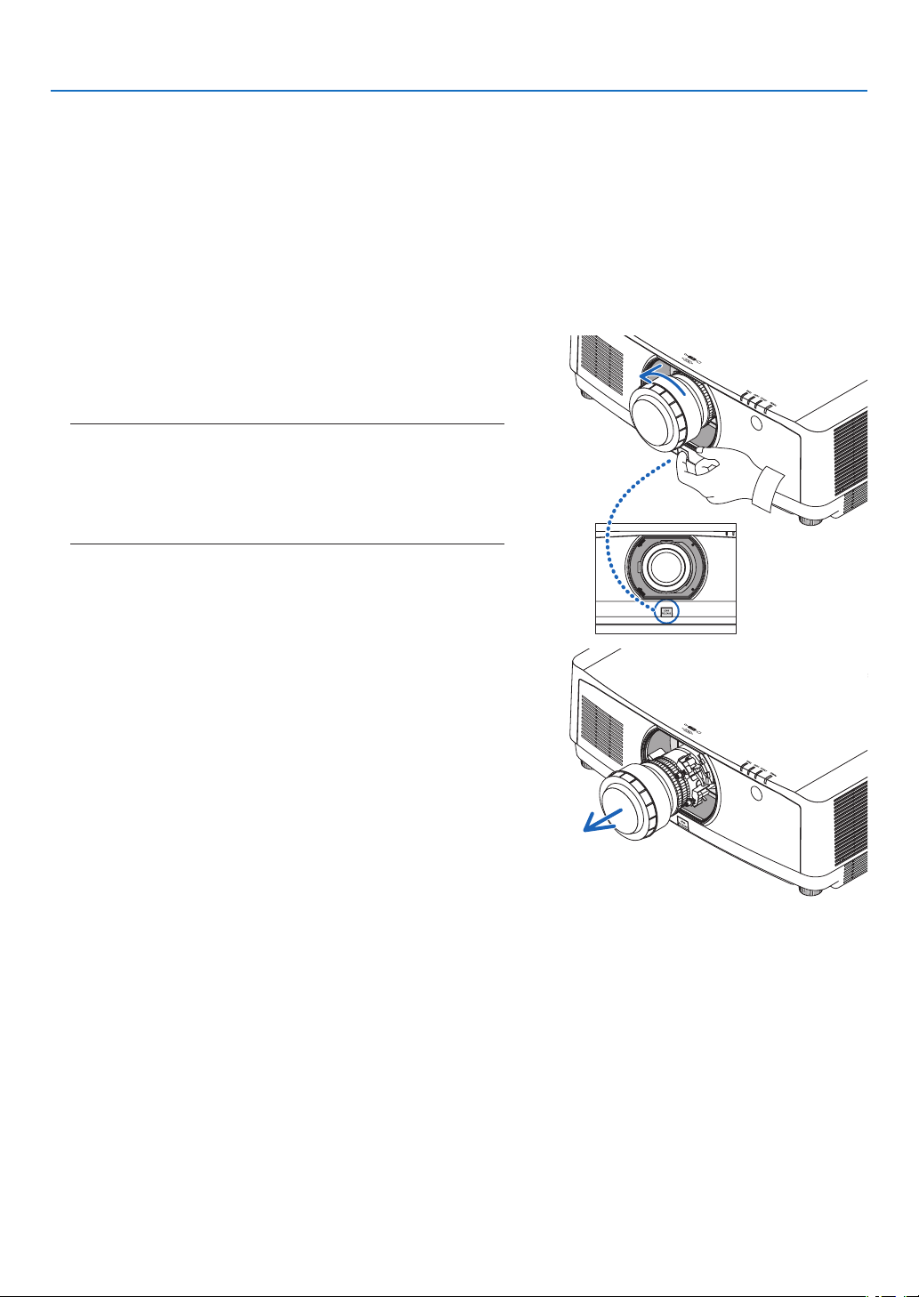
140
6. Connecting to Other Equipment
Removing the lens
Preparations:
1. Turn on the projector and display an image.
2. Press and hold the SHIFT/HOME POSITION button over 2 seconds.
The lens position will be moved to the home position.
3. Turn off the main power switch, and then unplug the power cord.
4. Wait until the projector cabinet is cool enough to handle.
Ifthelenstheftpreventionscrewhasbeenseton,removeitrst.
1.Whilepressingthelensreleasebuttonatthebottomof
lensmountingsectionontheprojector’sfrontpanelfully
in,turnthelenscounterclockwise.
The lens comes off.
NOTE:
•Checkthefollowingareasifthelensunitcannotberemovedeven
whenthelensreleasebuttonispressed.
1.Thelensreleasebuttonmaybelockedsometimes.Inthatcase,
turnthelensfullytotheright.Thelensreleasebuttonlockwill
bereleased.
2.Slowlypullthelensofftheprojector.
•Afterremovingthelens,mountthelenscaps(frontand
back) included with the lens before storing the lens.
•Ifnolensisgoingtobemountedontheprojector,mount
the dust cap included with the projector.
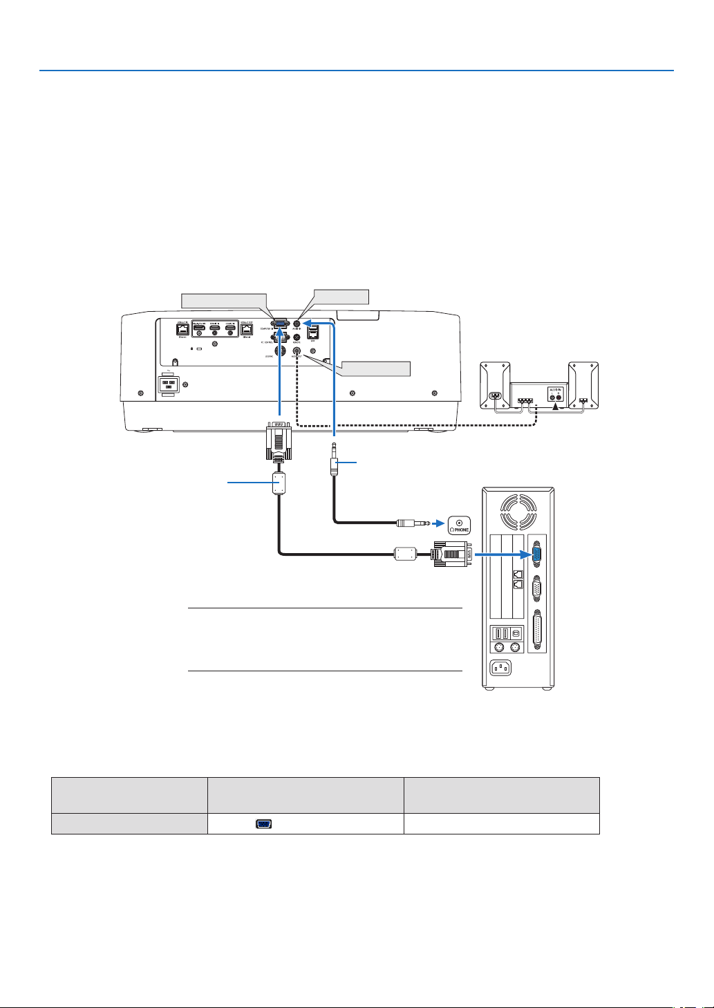
141
6. Connecting to Other Equipment
❷ Making Connections
Acomputercable,HDMIcable,oraDisplayPortcablecanbeusedtoconnecttoacomputer.
Theconnectioncableisnotenclosedwiththeprojector.Pleasegetreadyasuitablecablefortheconnection.
Analog RGB signal connection
•Connectthecomputercabletothemonitoroutterminal(miniD-sub15pin)onthecomputerandthecomputer
video input terminal on the projector. Please use a computer cable attached with a ferrite core.
•Selectthesourcenameforitsappropriateinputconnectorafterturningontheprojector.
InputconnectorINPUTbuttonontheprojector
cabinet
Buttonontheremotecontrol
COMPUTERIN
4:COMPUTER
4/COMPUTER
COMPUTER IN
AUDIO IN
AUDIO OUT
Stereo mini-plug audio cable (not supplied)
NOTE:
•Pleasechecktheoperatingmanualofthecomputeras
thename,positionanddirectionoftheterminalmay
differdependingonthecomputer.
Computer cable (sold commercially)
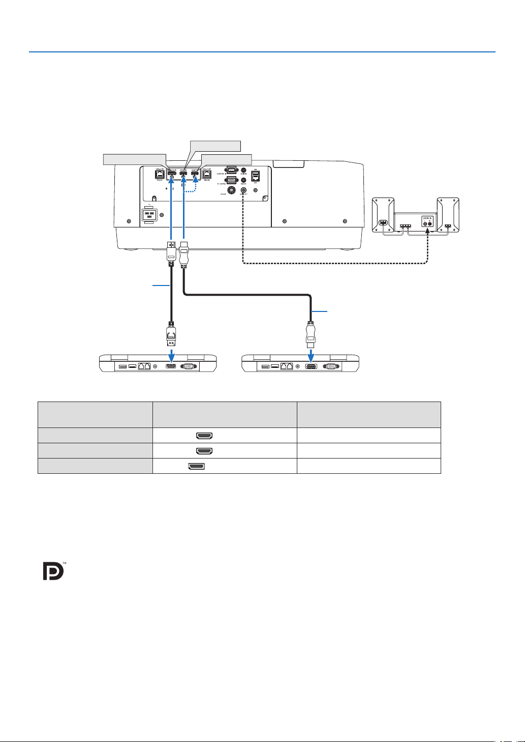
142
6. Connecting to Other Equipment
Digital RGB signal connection
•ConnectacommerciallyavailableHDMIcablebetweenthecomputer’sHDMIoutputconnectorandtheprojector’s
HDMI1INorHDMI2INconnector.
•ConnectacommerciallyavailableDisplayPortcablebetweenthecomputer’sDisplayPortoutputconnectorand
theprojector’sDisplayPortinputconnector.
•Selectthesourcenameforitsappropriateinputconnectorafterturningontheprojector.
InputconnectorINPUTbuttonontheprojector
cabinet
Buttonontheremotecontrol
HDMI1IN1:HDMI11/HDMI1
HDMI2IN
2:HDMI22/HDMI2
DisplayPortIN
3:DisplayPort
3/DisplayPort
CautionswhenconnectinganHDMIcable
•UseacertiedHighSpeedHDMI
®
CableorHighSpeedHDMI
®
CablewithEthernet.
Cautions when connecting a DisplayPort cable
•UseacertiedDisplayPortcable.
•Dependingonthecomputer,sometimemayberequireduntiltheimageisdisplayed.
•SomeDisplayPortcables(commerciallyavailable)havelocks.
•Todisconnectthecable,pressthebuttononthetopofthecable’sconnector,thenpullthecableout.
•IncasepowersupplyfromtheDisplayPortINterminalisrequired,pleasecontactyourdealer.
•WhensignalsfromadevicethatusesasignalconverteradapterareconnectedtotheDisplayPortinputconnector,
insomecasestheimagemaynotbedisplayed.
•WhentheHDMIoutputofacomputerisconnectedtotheDisplayPortinputconnector,useaconverter(commer-
cially available).
HDMI 1 IN
HDMI 2 IN
DisplayPort IN
HDMI cable (not supplied)
DisplayPort cable (not supplied)
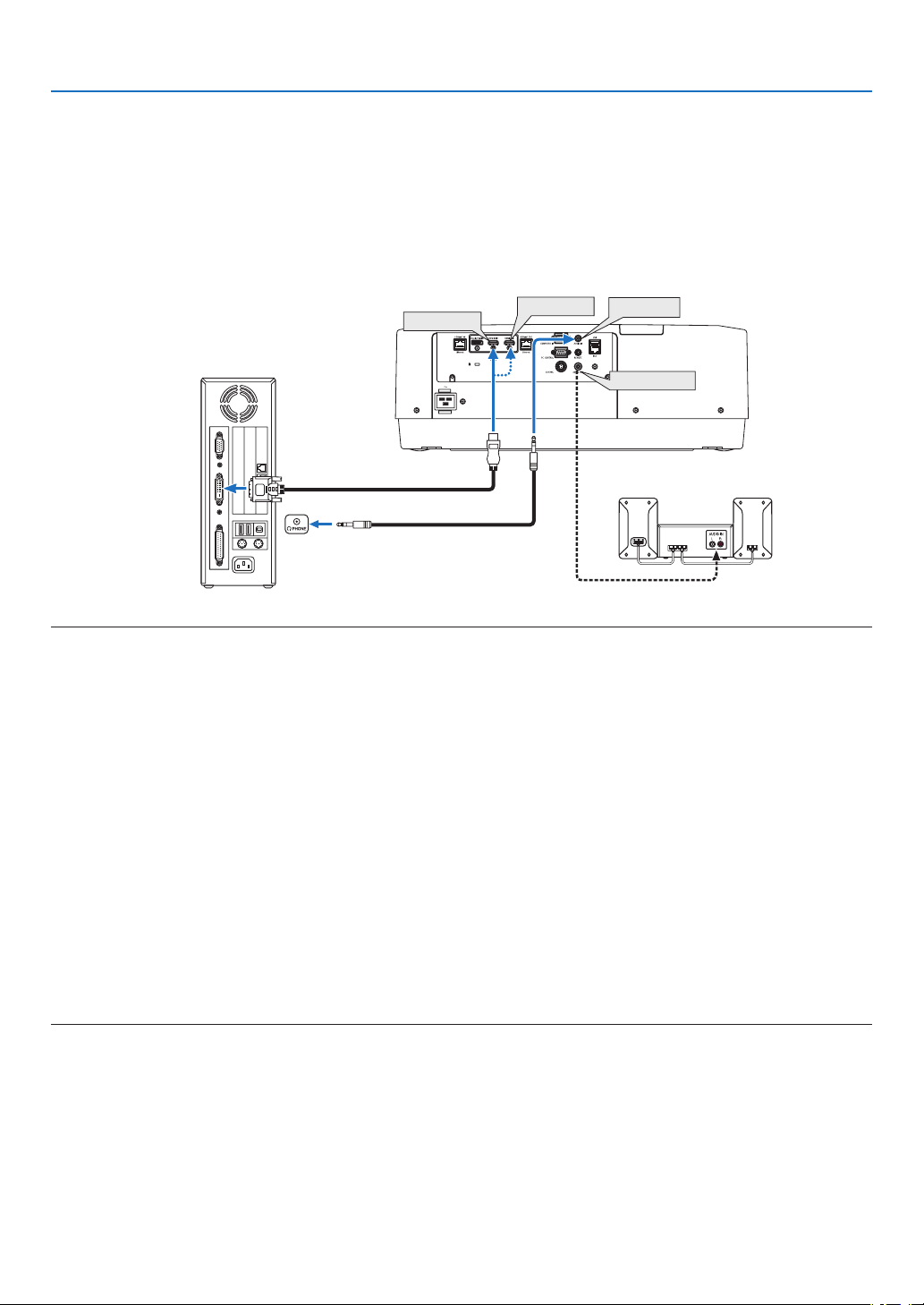
143
6. Connecting to Other Equipment
CautionswhenusingaDVIsignal
•WhenthecomputerhasaDVIoutputconnector,useacommerciallyavailableconvertercabletoconnectthe
computertotheprojector’sHDMI1INorHDMI2INconnector(onlydigitalvideosignalscanbeinput).Also,con-
nectthecomputer’saudiooutputtotheprojector’saudioinputconnector.Inthiscase,switchtheHDMI1orHDMI2
settingaton-screenmenu’saudioselectionontheprojectorto[COMPUTER].(→page
128)
Toconnectthecomputer’sDVIoutputconnectortotheprojector’sDisplayPortinputconnector,useacommercially
available converter.
HDMI 1 IN
HDMI 2 IN
AUDIO IN
AUDIO OUT
NOTE:WhenViewingaDVIDigitalSignal
•Turnoffthepowerofthecomputerandprojectorbeforeconnecting.
•Lowerthecomputer’svolumesettingbeforeconnectinganaudiocabletotheheadphonesconnector.Whenusingwithacomputer
connectedtotheprojector,adjustthevolumeofboththeprojectorandcomputertosettheappropriatevolumelevel.
•Ifthecomputerhasamini-jacktypeaudiooutputconnector,werecommendconnectingtheaudiocabletothatconnector.
•Whenavideodeckisconnectedviaascanconverter,etc.,thedisplaymaynotbecorrectduringfast-forwardingandrewinding.
•UseaDVI-to-HDMIcablecompliantwithDDWG(DigitalDisplayWorkingGroup)DVI(DigitalVisualInterface)revision1.0stan-
dard.Thecableshouldbewithin197"/5mlong.
•TurnofftheprojectorandthePCbeforeconnectingtheDVI-to-HDMIcable.
•ToprojectaDVIdigitalsignal:Connectthecables,turntheprojectoron,thenselecttheHDMIinput.Finally,turnonyourPC.
Failuretodosomaynotactivatethedigitaloutputofthegraphicscardresultinginnopicturebeingdisplayed.Shouldthishappen,
restartyourPC.
•SomegraphicscardshavebothanalogRGB(15-pinD-Sub)andDVI(orDFP)outputs.Useofthe15-pinD-Subconnectormay
resultinnopicturebeingdisplayedfromthedigitaloutputofthegraphicscard.
•DonotdisconnecttheDVI-to-HDMIcablewhiletheprojectorisrunning.Ifthesignalcablehasbeendisconnectedandthen
reconnected,animagemaynotbecorrectlydisplayed.Shouldthishappen,restartyourPC.
•TheCOMPUTERvideoinputconnectorssupportWindowsPlugandPlay.
•AMacsignaladapter(commerciallyavailable)mayberequiredtoconnectaMaccomputer.
ToconnectaMaccomputerequippedwithaMiniDisplayPorttotheprojector,useacommerciallyavailableMiniDisplayPort→
DisplayPortconvertercable.
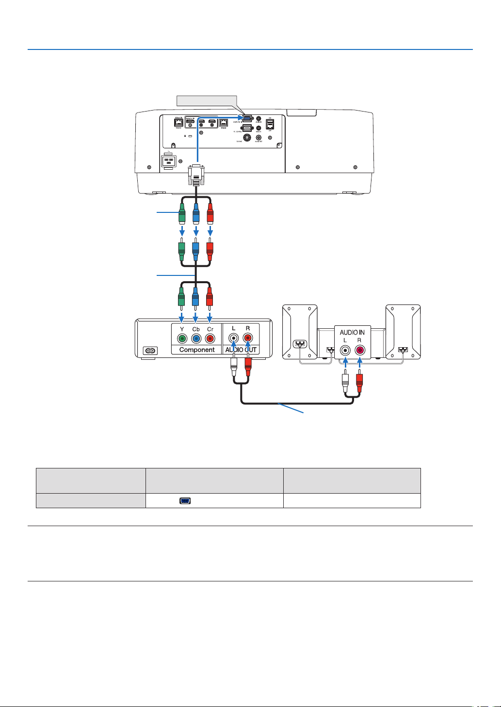
144
6. Connecting to Other Equipment
Connecting Component Input
•Selectthesourcenameforitsappropriateinputconnectorafterturningontheprojector.
InputconnectorINPUTbuttonontheprojector
cabinet
Buttonontheremotecontrol
COMPUTERIN
4:COMPUTER
4/COMPUTER
NOTE:
•Whenthesignalformatissetto[AUTO](defaultfactorysettingwhenshipped),thecomputersignalandcomponentsignalare
automaticallydistinguishedandswitched.Ifthesignalscannotbedistinguished,select[COMPONENT]under[ADJUST]→
[VIDEO]→[SIGNALTYPE]intheon-screenmenuoftheprojector.
•ToconnecttoavideodevicewithaDconnector,usethesoldseparatelyDconnectorconverteradapter(modelADP-DT1E).
COMPUTER IN
15-pin - to - RCA (female) × 3 cable
adapter (ADP-CV1E)
Stereo mini plug - to - RCA audio cable (not
supplied)
Component video RCA × 3 cable
(not supplied)
Blu-ray player
Audio Equipment
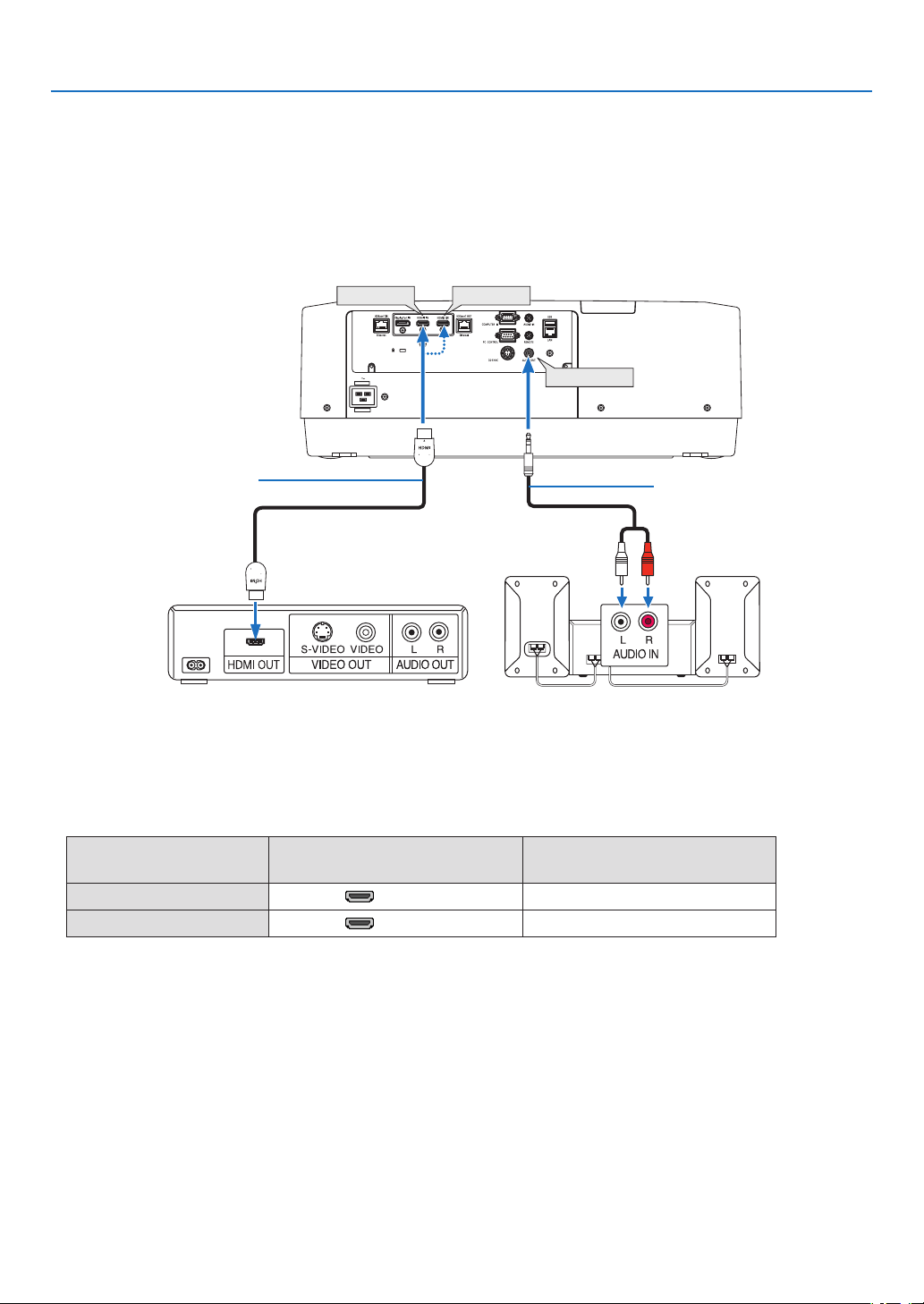
145
6. Connecting to Other Equipment
Connecting HDMI Input
YoucanconnecttheHDMIoutputofyourBlu-rayplayer,harddiskplayer,ornotebooktypePCtotheHDMI1INor
HDMI2INconnectorofyourprojector.
InputconnectorINPUTbuttonontheprojector
cabinet
Buttonontheremotecontrol
HDMI1IN
1:HDMI11/HDMI1
HDMI2IN2:HDMI22/HDMI2
TIP:ForusersofaudiovideoequipmentwithanHDMIconnector:
Select“Enhanced”ratherthan“Normal”ifHDMIoutputisswitchablebetween“Enhanced”and“Normal”.
Thiswillprovideimprovedimagecontrastandmoredetaileddarkareas.
Formoreinformationonsettings,refertotheinstructionmanualoftheaudiovideoequipmenttobeconnected.
•WhenconnectingtheHDMI1INorHDMI2INconnectoroftheprojectortotheBlu-rayplayer,theprojector’svideo
levelcanbemadesettingsinaccordancewiththeBlu-rayplayer’svideolevel.Inthemenuselect[ADJUST]→
[VIDEO]→[VIDEOLEVEL]andmakenecessarysettings.
•IftheHDMIinput’ssoundisnotoutput,checkif[HDMI1]and[HDMI2]areset[HDMI1]and[HDMI2]correctlythe
on-screenmenu[SETUP]→[SOURCEOPTIONS]→[AUDIOSELECT].(→page
128)
HDMI 1 IN
HDMI 2 IN
AUDIO OUT
Audio cable (not supplied)
HDMI cable (not supplied)
Use High Speed HDMI
®
Cable.
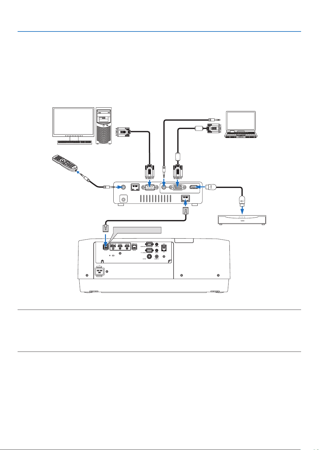
146
6. Connecting to Other Equipment
Connecting to a HDBaseT transmission device (sold commercially)
UseaLANcablesoldcommerciallytoconnecttheHDBaseTIN/Ethernetportoftheprojector(RJ-45)toaHDBaseT
transmission device sold commercially.
TheHDBaseTIN/EthernetportoftheprojectorsupportsHDMIsignals(HDCP)fromtransmissiondevices,control
signalsfromexternaldevices(serial,LAN)andremotecontrolsignals(IRcommands).
•Refertotheowner’smanualaccompaniedwithyourHDBaseTtransmissionforconnectingwithyourexternalde-
vices.
Connection example
RS-232CLAN
AUDIO IN HDMI IN
Wired-Remote
DC IN
HDBaseT
COMPUTER IN
HDBaseT IN/Ethernet
Computer (for control use)
Computer (for output use)
Example of a transmission device
Our company’s remote
control (RD-465E)
HDMI output video device
NOTE:
•Pleaseuseashieldedtwistedpair(STP)cableofCategory5eorhigherfortheLANcable(soldcommercially).
•ThemaximumtransmissiondistanceovertheLANcableis100m.(themaximumdistanceis70mfora4Ksignal)
•Pleasedonotuseothertransmissionequipmentbetweentheprojectorandtransmissionequipment.Thepicturequalitymaybe
degradedasaresult.
•ThisprojectorisnotguaranteedtoworkwithallHDBaseTtransmissiondevicessoldcommercially.
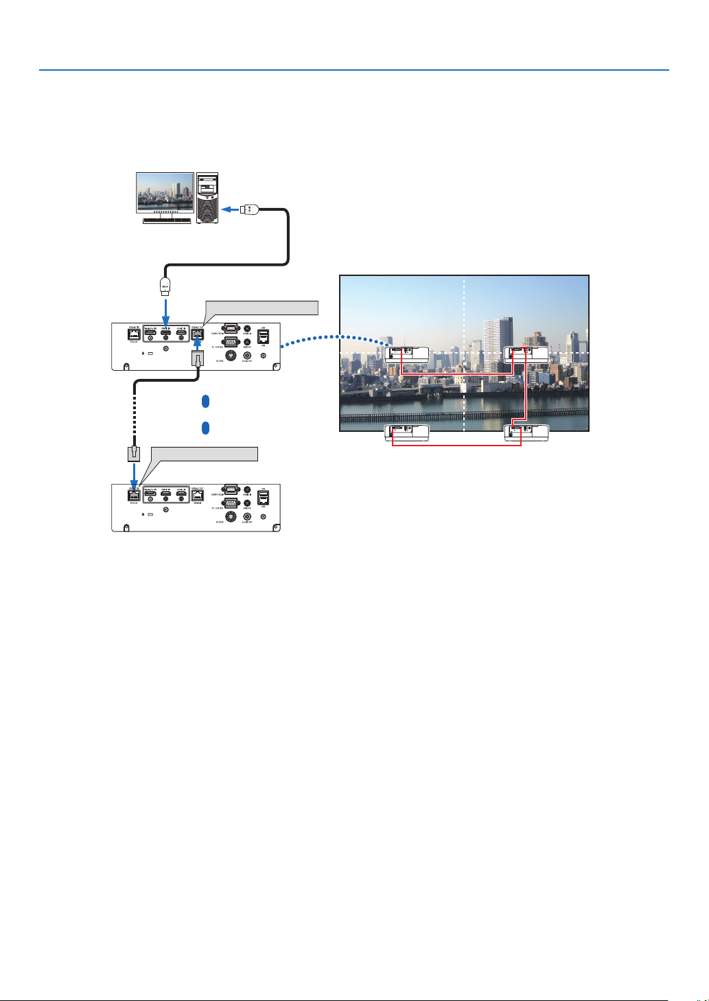
147
6. Connecting to Other Equipment
Connecting several projectors
ItenablestoprojectHDMI,DisplayPort,HDBaseTimageonseveralprojectorsconnectingtheHDBaseTIN/Ethernet
portandtheHDBaseTOUT/EthernetportbyLANcable.Theprojectorssupportsamebrightnesscanbeconnected
uptofourunits,
HDBaseT OUT/Ethernet
HDBaseT IN/Ethernet
•ThesignalfromtheCOMPUTERINterminalisnotoutputfromtheHDBaseTOUT/Ethernetportofthisprojector.
•PA803ULandPA653ULcannotbeconnected.Atthesametime,thisprojectorisnotguaranteedtoworkcorrectly
in the connection with an other device as a monitor.
•WhenoutputtingHDMIsignals,turnonthepowerofthevideodeviceontheoutputsideandkeepitconnected
beforeinputtingvideosignalsintothisdevice.TheHDMIoutputterminalsoftheprojectorareequippedwithrepeater
functions.WhenadeviceisconnectedtotheHDMIoutputterminal,theresolutionoftheoutputsignalislimitedby
the resolution supported by the connected device.
•ConnectinganddisconnectinganHDMIcableorselectinganotherinputsourceonthesecondandsubsequent
projectorswilldisabletheHDMIrepeaterfunction.
Master projector
Other projector
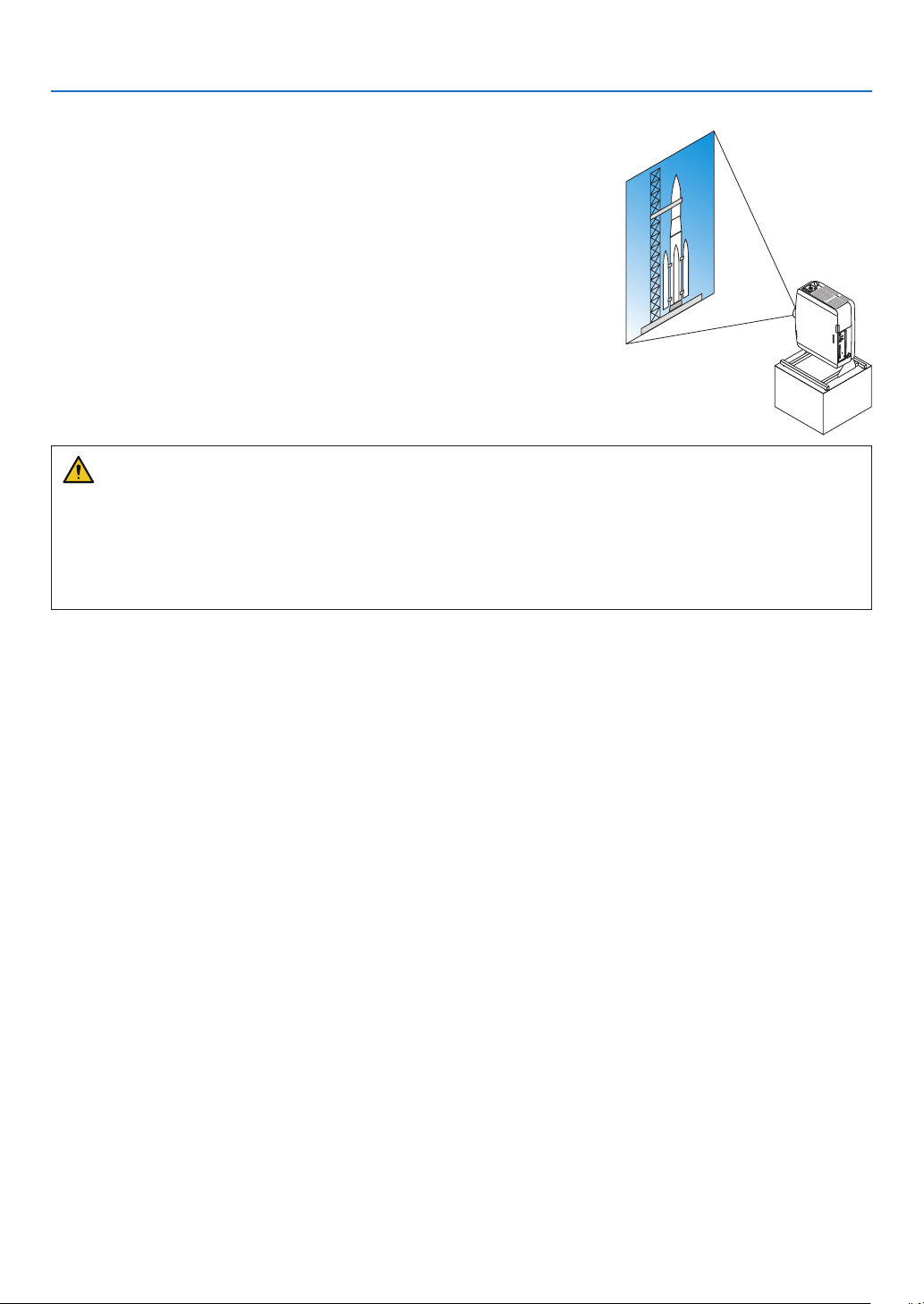
148
6. Connecting to Other Equipment
Portrait projection (vertical orientation)
Portraitscreensfromacomputercanbeprojectedbyinstallingtheprojec-
torinaverticalorientation.Angletodisplayallthescreenssuchasthe
on-screenmenucanbechangedbythemenu[SETUP]→[MENU(2)]
→[MENUANGLE].
Precautions during installation
•Pleasedonotinstalltheprojectorinaverticalorientationontopoftheoorortableonitsown.Theintakevent
maybeobstructed,resultingintheprojectorgettingwarmandthepossibilityofreandmalfunctionoccurring.
•Astandforsupportingtheprojectorneedstobemadeforportraitprojectionandforinstallingtheprojectorin
universalangle.Inthiscase,thestandmustbedesignedsuchthatthecenterofgravityoftheprojectorislocated
wellwithinthelegsofthestand.Ifnot,theprojectormayfalloverandresultininjury,damageandmalfunction.
Designandmanufacturingconditionsforthestand
Pleaseengageaninstallationserviceproviderforthedesignandmanufactureofthecustomizedstandtobeusedfor
portraitprojection.Pleaseensurethatthefollowingarecompliedwithwhendesigningthestand.
1.Securesufficientspacebetweentheprojectorandtheoor:
*Installationfacingtheintakeventdownward:130mmorgreater.
Installationfacingtheexhaustventdownward:200mmorgreater.
2. Usethefourscrewholesatthebackoftheprojectortosecureittothestand.
Screwholecenterdimension:200×250mm
Screwholedimensionontheprojector:M4withamaximumdepthof8mm.
*Pleasedesignthestandsuchthattherearlegsatthebackoftheprojectordonotcontactthestand.Thefront
legscanbeturnedandremoved.
3. Horizontaladjustmentmechanism(forexample,boltsandnutsinfourlocations)
4. Pleasedesignthestandsuchthatitdoesnottoppleovereasily.
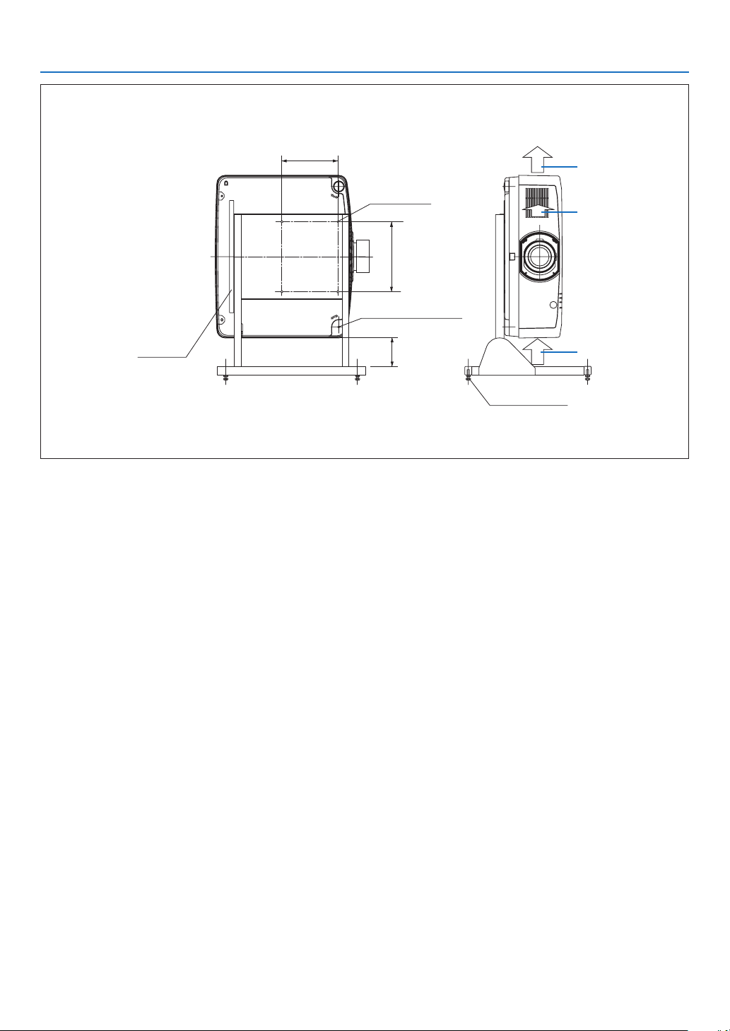
149
6. Connecting to Other Equipment
Referencedrawings
*Thedrawingshowingthedimensionalrequirementsisnotanactualstanddesigndrawing.
[Side View] [Front View]
Screw holes for 4 - M4 use
Tilt foot (remove)
130 or
greater**
200
Horizontal adjuster
Exhaust
Intake air
Intake airRear foot
250
**Pleaserefertothepreviouspage.
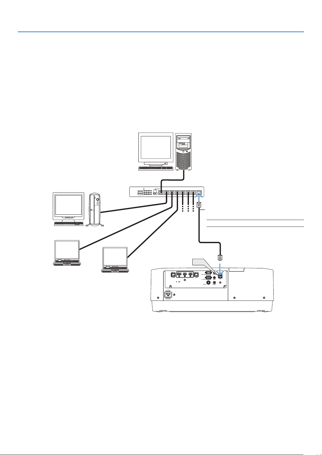
150
6. Connecting to Other Equipment
Connecting to a Wired LAN
TheprojectorcomesstandardwithaLANport(RJ-45)whichprovidesaLANconnectionusingaLANcable.
TouseaLANconnection,youarerequiredtosettheLANontheprojectormenu.Select[SETUP]→[NETWORK
SETTINGS]→[WIREDLAN].(→page
124).
ExampleofLANconnection
ExampleofwiredLANconnection
LAN
Server
Hub
LAN cable (not supplied)
NOTE:UseaCategory5orhigherLANcable.
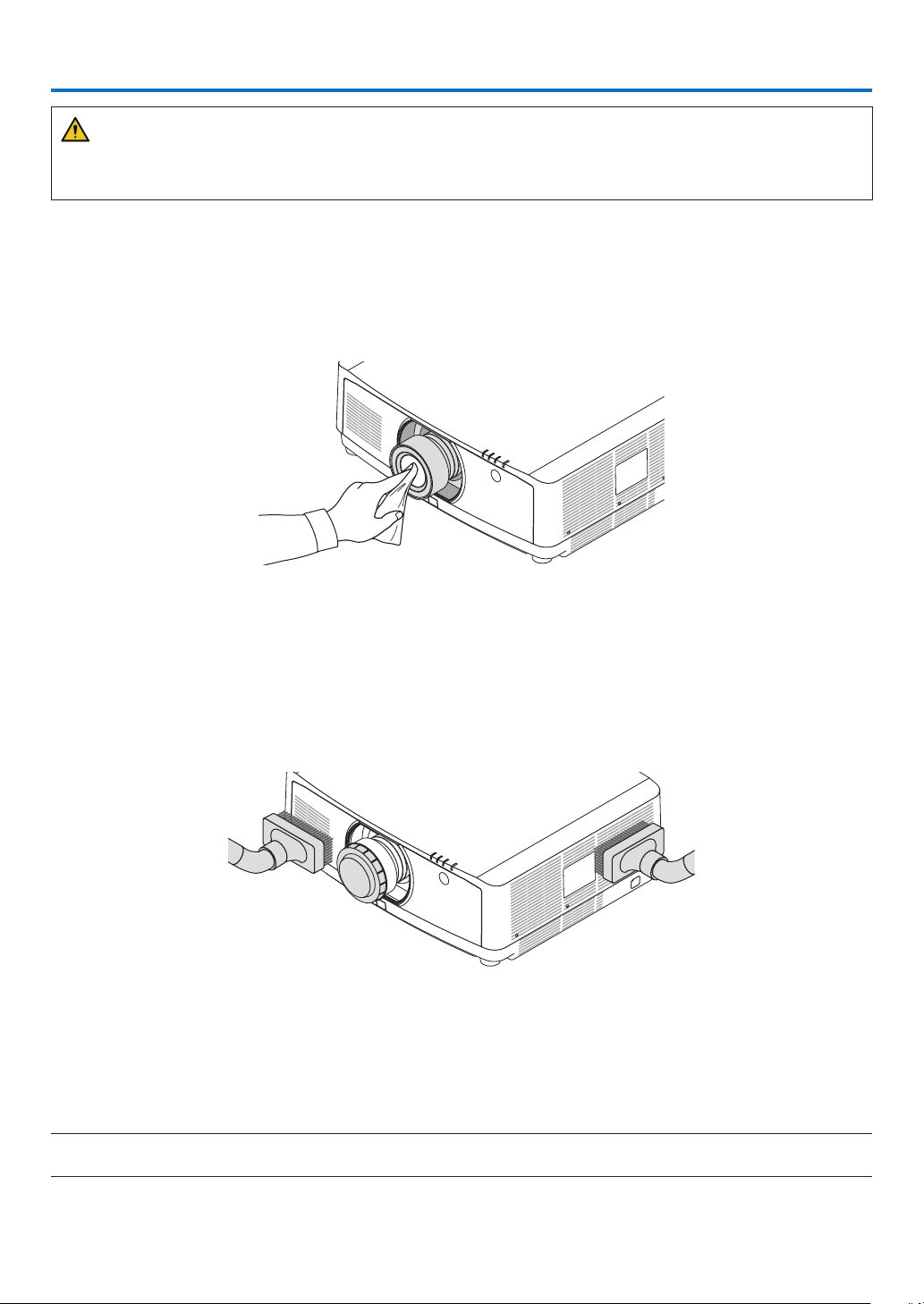
151
7. Maintenance
WARNING
•Pleasedonotuseaspraycontainingammablegastoremovedustattachedtothelensandcabinet.Doingso
mayresultinres.
❶ Cleaning the Lens
•Turnofftheprojectorbeforecleaning.
•Theprojectorhasaplasticlens.Useacommerciallyavailableplasticlenscleaner.
•Donotscratchormarthelenssurfaceasaplasticlensiseasilyscratched.
•Neverusealcoholorglasslenscleanerasdoingsowillcausedamagetotheplasticlenssurface.
❷ Cleaning the Cabinet
Turnofftheprojector,andunplugtheprojectorbeforecleaning.
•Useadrysoftclothtowipedustoffthecabinet.
Ifheavilysoiled,useamilddetergent.
•Neverusestrongdetergentsorsolventssuchasalcoholorthinner.
•Whencleaningtheventilationslitsorthespeakerusingavacuumcleaner,donotforcethebrushofthevacuum
cleaner into the slits of the cabinet.
Vacuum the dust off the ventilation slits.
•Cloggedventilationslitsmaycauseariseintheinternaltemperatureoftheprojector,resultinginmalfunction.
•Donotscratchorhitthecabinetwithyourngersoranyhardobjects
•Contactyourdealerforcleaningtheinsideoftheprojector.
NOTE:Donotapplyvolatileagentsuchasinsecticideonthecabinet,thelens,orthescreen.Donotleavearubberorvinylproduct
inprolongedcontactwithit.Otherwisethesurfacenishwillbedeterioratedorthecoatingmaybestrippedoff.
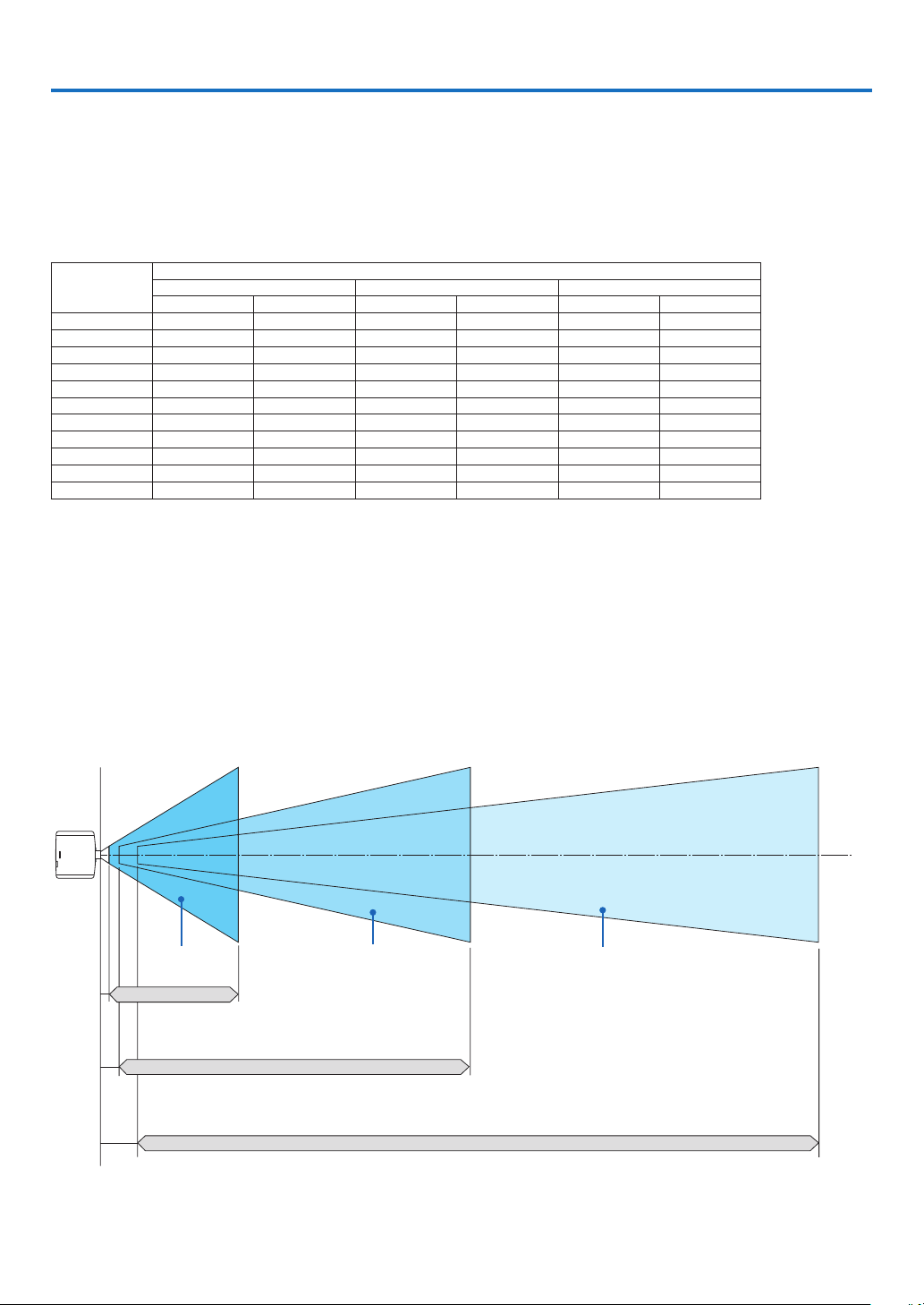
152
8. Appendix
❶ Throw distance and screen size
Threeseparatebayonetstylelensescanbeusedonthisprojector.Refertotheinformationonthispageandusea
lenssuitedfortheinstallationenvironment(screensizeandthrowdistance).Forinstructionsonmountingthelens,
seepage
138.
Lens types and throw distance
Screensize
(inches)
Lens model name
NP40ZL NP41ZL NP42ZL
(inches) (m) (inches) (m) (inches) (m)
50 33 - 46 0.8 - 1.2 54 - 127 1.4 - 3.2 125 - 245 3.2 - 6.2
60 39 - 56 1.1 - 1.4 66 - 153 1.7 - 3.9 149 - 293 3.8 - 7.4
80 53 - 75 1.4 - 1.9 88 - 204 2.2 - 5.2 197 - 389 5.0 - 9.9
100 67 - 94 1.7 - 2.4 110 - 256 2.8 - 6.5 245 - 485 6.2 - 12.3
120 81 - 114 2.0 - 2.9 133 - 307 3.4 - 7.8 292 - 581 7.4 - 14.8
150 101 - 142 2.6 - 3.6 166 - 384 4.2 - 9.8 364 - 725 9.3 - 18.4
200 135 - 190 3.4 - 4.8 223 - 513 5.7 - 13.0 484 - 965 12.3 - 24.5
240 163 - 229 4.1 - 5.8 267 - 616 6.8 - 15.6 580 - 1157 14.7 - 29.4
300 204 - 286 5.2 - 7.3 335 - 770 8.5 - 19.6 723 - 1446 18.4 - 36.7
400 272 - 382 6.9 - 9.7 447 - 1028 11.4 - 26.1 963 - 1926 24.5 - 48.9
500 340 - 478 8.6 - 12.1 559 - 1285 14.2 - 32.6 1202 - 2407 30.5 - 61.1
TIP
Calculationofthethrowdistancefromthescreensize
NP40ZLlensthrowdistance(inch/m)=Hx0.8toHx1.1:33"/0.8m(min.)to478"/12.1m(max.)
NP41ZLlensthrowdistance(inch/m)=Hx1.3toHx3.0:54"/1.4m(min.)to1285"/32.6m(max.)
NP42ZLlensthrowdistance(inch/m)=Hx2.9toHx5.7:125"/3.2m(min.)to2407"/61.1m(max.)
“H”(Horizontal)referstothescreenwidth.
*Figuresdifferbyseveral%withthetableabovebecausethecalculationisapproximate.
Ex.:Throwdistancewhenprojectingona150"screenusingtheNP41ZLlens:
Accordingtothe“ScreenSize(forreference)”table(→page
153),H(screenwidth)=127.2"/323.1cm.
Thethrowdistanceis127.2"/323.1cm×1.3to127.2"/323.1cm×3.0=165"/420.0cmto382"/969.3cm(becauseofthezoomlens).
Projectionrangeforthedifferentlenses
50-500" 50-500" 50-500"
NP40ZL : 33" - 478"/0.8 - 12.1 m
NP41ZL : 54" - 1285"/1.4 - 32.6 m
NP42ZL : 125" - 2407"/3.2 - 61.1 m
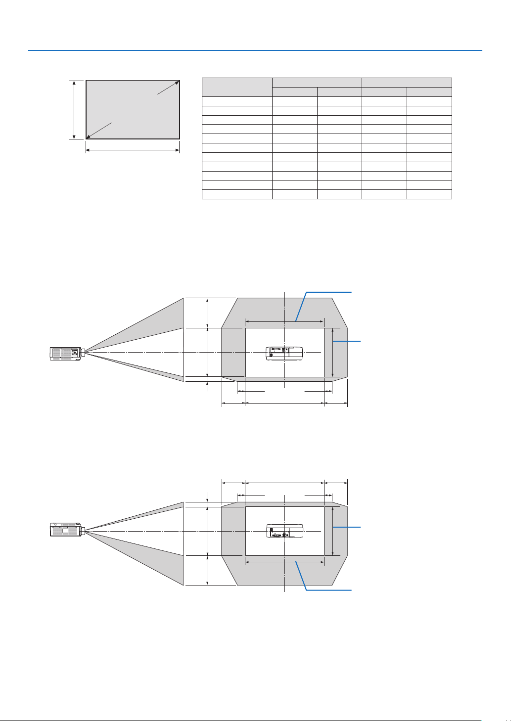
153
8. Appendix
Tables of screen sizes and dimensions
Screen
height
Screen width
16:10 screen size (di-
agonal)
Size(inches)ScreenwidthScreenheight
(inches) (cm) (inches) (cm)
50 42.4 107.7 26.5 67.3
60 50.9 129.2 31.8 80.8
80 67.8 172.3 42.4 107.7
100 84.8 215.4 53.0 134.6
120 101.8 258.5 63.6 161.5
150 127.2 323.1 79.5 201.9
200 169.6 430.8 106.0 269.2
240 203.5 516.9 127.2 323.1
300 254.4 646.2 159.0 403.9
400 339.2 861.6 212.0 538.5
500 424.0 1077.0 265.0 673.1
Lens shifting range
Thisprojectorisequippedwithalensshiftfunctionforadjustingthepositionoftheprojectedimagebybuttons.The
lenscanbeshiftedwithintherangeshownbelow.
Desk/frontprojection
100%V
100%H
10%H 10%H
50%V
10%V
20%H 20%H
Width of projected image
Height of projected image
Descriptionofsymbols:Vindicatesvertical(heightoftheprojectedimage),Hindicateshorizontal(widthofthepro-
jectedimage).
Ceiling/frontprojector
100%V
100%H
10%H
10%H
50%V
10%V
20%H 20%H
Height of projected image
Width of projected image

154
8. Appendix
Example:Whenprojectingona150"screen
Accordingtothetablesofscreensizesanddimensions(→page
153),H=127.2"(323.1cm),V=79.5"(201.9cm).
Adjustmentrangeintheverticaldirection:Theprojectedimagecanbemovedupwards0.5×79.5"(201.9cm)≈39.6"
(101cm),downwards0.1×79.5"(201.9cm)≈8"(20cm)(whenthelensisatthecenterposition).Foraceiling/front
installation,theaboveguresareinverted.
Adjustmentrangeinthehorizontaldirection:Theprojectedimagecanbemovedtotheleft0.2×127.2"(323.1cm)≈
25.5"(64.5cm),totheright0.2×127.2"(323.1cm)≈25.5"(64.5cm).
*Figuresdifferbyseveral%becausethecalculationisapproximate.

155
8. Appendix
❷ Compatible Input Signal List
HDMI/HDBaseT
SignalResolution(dots)AspectRatioRefreshRate(Hz)
VGA640 ×480 4 : 3 60/72/75/85/iMac
SVGA800 ×600 4 : 3 56/60/72/75/85/iMac
XGA1024 ×768 4 : 3 60/70/75/85/iMac
HD1280 ×720 16 : 9 60
WXGA
1280 ×768 15 : 9 60
1280 ×800 16 : 10 60
Quad-VGA1280 ×960 4 : 3 60
SXGA1280 ×1024 5 : 4 60
FWXGA
1360 ×768 16 : 9 60
1366 ×768 16 : 9 60
SXGA+1400 ×1050 4 : 3 60
WXGA+1440 ×900 16 : 10 60
WXGA++1600 ×900 16 : 9 60
WSXGA+1680 ×1050 16 : 10 60
UXGA1600 ×1200 *4 : 3 60
FullHD1920 ×1080 *16 : 9 60
WUXGA1920 ×1200 *16 : 10 60(ReducedBlanking)
2K2048 ×1080 17 : 9 60
WQHD
iMac 27"
2560 ×1440 16 : 9 60
WQXGA2560 ×1600 16 : 10 60(ReducedBlanking)
4K
3840 ×2160 16 : 9 24/25/30/50/60
4096 ×2160 17 : 9 24/25/30/50/60
HDTV(1080p)1920 ×1080 *16 : 9 24/25/30/50/60
HDTV(1080i)1920 ×1080 *16 : 9 48/50/60
HDTV(720p)1280 ×720 16 : 9 50/60
SDTV(480p)720/1440 ×480 4:3 / 16:9 60
SDTV(576p)720/1440 ×576 4:3 / 16:9 50
SDTV(480i)1440 ×480 4:3 / 16:9 60
SDTV(576i)1440 ×576 4:3 / 16:9 50
DisplayPort
SignalResolution(dots)AspectRatioRefreshRate(Hz)
VGA640 ×480 4 : 3 60
SVGA800 ×600 4 : 3 60
XGA1024 ×768 4 : 3 60
HD1280 ×720 16 : 9 60
WXGA
1280 ×768 15 : 9 60
1280 ×800 16 : 10 60
Quad-VGA1280 ×960 4 : 3 60
SXGA1280 ×1024 5 : 4 60
FWXGA
1360 ×768 16 : 9 60
1366 ×768 16 : 9 60
SXGA+1400 ×1050 4 : 3 60
WXGA+1440 ×900 16 : 10 60
WXGA++1600 ×900 16 : 9 60
WSXGA+1680 ×1050 16 : 10 60
UXGA1600 ×1200 *4 : 3 60
FullHD1920 ×1080 *16 : 9 60
WUXGA1920 ×1200 *16 : 10 60(ReducedBlanking)
2K2048 ×1080 17 : 9 60
WQHD
iMac 27"
2560 ×1440 16 : 9 60
WQXGA2560 ×1600 16 : 10
60(ReducedBlanking)
4K
3840 ×2160 16 : 9 24/25/30/50/60
4096 ×2160 17 : 9 24/25/30/50/60
HDTV(1080p)1920 ×1080 16 : 9 24/25/30/50/60
HDTV(720p)1280 ×720 16 : 9 50/60
SDTV(480i/p)720/1440 ×480 4:3 / 16:9 60
SDTV(576i/p)720/1440 ×576 4:3 / 16:9 50

156
8. Appendix
AnalogRGB
SignalResolution(dots)AspectRatioRefreshRate(Hz)
VGA640 ×480 4 : 3 60/72/75/85/iMac
SVGA800 ×600 4 : 3 56/60/72/75/85/iMac
XGA1024 ×768 4 : 3 60/70/75/85/iMac
XGA+1152 ×864 4 : 3 75
HD1280 ×720 16 : 9 60
WXGA
1280 ×768 15 : 9 60/75/85
1280 ×800 16 : 10 60/75/85
Quad-VGA1280 ×960 4 : 3 60/85
SXGA1280 ×1024 5 : 4 60/75/85
FWXGA
1360 ×768 16 : 9 60
1366 ×768 16 : 9 60
SXGA+1400 ×1050 4 : 3 60/75
WXGA+1440 ×900 16 : 10 60/75/85
WXGA++1600 ×900 16 : 9 60
UXGA1600 ×1200 *4 : 3 60
WSXGA+1680 ×1050 16 : 10 60
FillHD1920 ×1080 *16 : 9 60
WUXGA1920 ×1200 *16 : 10 60(ReducedBlanking)
2K2048 ×1080 17 : 9 60
FullHD1920 ×1080 *16 : 9 60
MAC13"640 ×480 4 : 3 67
MAC16"832 ×624 4 : 3 75
MAC19"1024 ×768 4 : 3 75
MAC21"1152 ×870 4 : 3 75
MAC23"1280 ×1024 5 : 4 65
Analog Component
SignalResolution(dots)AspectRatioRefreshRate(Hz)
HDTV(1080p)1920 ×1080 16 : 9 50/60
HDTV(1080i)1920 ×1080 16 : 9 48/50/60
HDTV(720p)1280 ×720 16 : 9 50/60
SDTV(480p)720 ×480 4:3 / 16:9 60
SDTV(576p)720 ×576 4:3 / 16:9 50
SDTV(480i)720 ×480 4:3 / 16:9 60
SDTV(576i)720 ×576 4:3 / 16:9 50
157
8. Appendix
HDMI/HDBaseT3D
SignalResolution(dots)AspectRatioRefreshRate(Hz)3DFormat
1920 ×1080p
16 : 9
23.98/24
FramePacking
SideBySide(Half)
TopAndBottom
25
SideBySide(Half)
TopAndBottom
29.97/30
FramePacking
SideBySide(Half)
TopAndBottom
50
SideBySide(Half)
TopAndBottom
59.94/60
SideBySide(Half)
TopAndBottom
1920 ×1080i
50
SideBySide(Half)
TopAndBottom
59.94/60
SideBySide(Half)
TopAndBottom
1280 ×720p
23.98/24
FramePacking
SideBySide(Half)
TopAndBottom
25
SideBySide(Half)
TopAndBottom
29.97/30
FramePacking
SideBySide(Half)
TopAndBottom
50
FramePacking
SideBySide(Half)
TopAndBottom
59.94/60
FramePacking
SideBySide(Half)
TopAndBottom
DisplayPort 3D
SignalResolution(dots)AspectRatioRefreshRate(Hz)3DFormat
1920 ×1080p
16 : 9
23.98/24
FramePacking
SideBySide(Half)
TopAndBottom
25
SideBySide(Half)
TopAndBottom
29.97/30
FramePacking
SideBySide(Half)
TopAndBottom
50
SideBySide(Half)
TopAndBottom
59.94/60
SideBySide(Half)
TopAndBottom
1280 ×720p
23.98/24
FramePacking
SideBySide(Half)
TopAndBottom
25
SideBySide(Half)
TopAndBottom
29.97/30
FramePacking
SideBySide(Half)
TopAndBottom
50
FramePacking
SideBySide(Half)
TopAndBottom
59.94/60
FramePacking
SideBySide(Half)
TopAndBottom
*Nativeresolution
•Signalsexceedingtheprojector’sresolutionarehandledwithAdvancedAccuBlend.
•WithAdvancedAccuBlend,thesizeofcharactersandruledlinesmaybeunevenandcolorsmaybeblurred.
•Uponshipment,theprojectorissetforsignalswithstandarddisplayresolutionsandfrequencies,butadjustmentsmayberequired
dependingonthetypeofcomputer.

158
8. Appendix
❸ Specifications
Model name PA803UL/PA653UL
Method
Threeprimarycolorliquidcrystalshutterprojectionmethod
Specicationsofmainparts
Liquidcrystal
panel
Size0.76"(withMLA)×3(aspectratio:16:10)
Pixels
(*1)
2,304,000(1920dots×1200lines)
Projection lenses
Refertothespecicationsofoptionlens(→
160page)
LightsourceLaser diode
OpticaldeviceIntegrator,DichroicMirror,XDP
Lightoutput
(*2)
(*3)
ECOOFFPA803UL: 8000 lm
PA653UL: 6500 lm
Contrastratio
(*2)
(allwhite/allblack)2500000:1 with dynamic contrast
Screensize(throwdistance)50" to 500"
Colorreproducibility10-bitcolorprocessing(approx.1.07billioncolors)
ScanningfrequencyHorizontalAnalog:15kHz,24to100kHz(24kHzorgreaterforRGBinputs),conformingto
VESAstandards
Digital:15kHz,24to153kHz,conformingtoVESAstandards
Vertical Analog:48Hz,50to85Hz,100,120HzconformingtoVESAstandards
Digital:24,25,30,48Hz,50to85Hz,100,120HzconformingtoVESAstandards
Main adjustment functions MotorizedZoom,MotorizedFocus,MotorizedLensShift,inputsignalswitching
(HDMI1/HDMI2/DisplayPort/COMPUTER/HDBaseT),autoimageadjustment,picture
enlarging,picturepositionadjustment,muting(bothvideoandaudio),poweron/
standby,on-screendisplay/selection,etc.
Max.displayresolution(horizontal×
vertical)
AnalogWUXGA(1920×1200)withAdvancedAccuBlendPixelclockfrequency:less
than165MHz
DigitalQuadHD(4096×2160)withAdvancedAccuBlendPixelclockfrequency:less
than600MHz(HDBaseT:300MHz)
Inputsignals
R,G,B,H,V
RGB:0.7Vp-p/75Ω
Y:1.0Vp-p/75Ω(withNegativePolaritySync)
Cb,Cr(Pb,Pr):0.7Vp-p/75Ω
H/VSync:4.0Vp-p/TTL
CompositeSync:4.0Vp-p/TTL
SynconG:1.0Vp-p/75Ω(withSync)
Component
Y:1.0Vp-p/75Ω(withSync)
Cb,Cr(Pb,Pr):0.7Vp-p/75Ω
DTV:480i,480p,720p,1080i,1080p(60Hz)
576i,576p,720p,1080i(50Hz)
DVD:Progressivesignal(50/60Hz)
Audio
0.5Vrms/22kΩorgreater
Input/outputconnectors
Computer/Com-
ponent
Video input MiniD-Sub15-pin×1
Audio input Stereominijack×1
Audio output Stereominijack×1(commonforallsignals)
HDMIVideo input HDMI
®
ConnectortypeA×2
RJ-450×1,100BASE-TXcompatible
DeepColor(colordepth):8-/10-/12-bitcompatible
Colorimetry:RGB,YCbCr444,YCbCr422,YCbCr420,REC2020,REC709,REC601
SupportsLipSync,HDCP
(*4)
,4KHDRand3D
Audio input HDMI:Samplingfrequency–32/44.1/48kHz,Samplingbits–16/20/24bits
HDBaseT/Eth-
ernet
Video input DeepColor(colordepth):Support8/10/12bits
Colorimetry:SupportRGB,YCbCr444,YCbCr422,YCbCr420,REC2020,REC709,
REC601
SupportLipSync,HDCP
(*4)
,4K,3D,HDR
Video output RJ-45x1,100BASE-TX
DeepColor(colordepth):Support8/10/12bits
Colorimetry:SupportRGB,YCbCr444,YCbCr422,REC709,REC601
SupportLipSync,HDCP
(*4)
,4K,3D
Audio input Samplingfrequency:32/44.1/48kHz
Samplingbit:16/20/24bit
Audio output Samplingfrequency:32/44.1/48kHz
Samplingbit:16/20/24bits
159
8. Appendix
Model name PA803UL/PA653UL
DisplayPortVideo input
DisplayPort×1
Datarate:5.4Gbps/2.7Gbps/1.62Gbps
No. lanes: 1 lane/2 lanes/4 lanes
Colordepth:8bits,10bits,12bits
Colorimetry:RGB,YCbCr444,YCbCr422,REC709,REC601
HDCPcompatible
(*4)
Audio input DisplayPort:Samplingfrequency–32/44.1/48kHz,Samplingbits–16/20/24bits
PCcontrolterminalD-Sub9-pin×1
USBportUSBtypeA×1
Ethernet/LAN/HDBaseTportRJ-45×1,Supports10BASE-T/100BASE-TX
RemoteterminalStereominijack×1
3DSYNCoutputterminal5V/10mA,synchronizedsignaloutputfor3Duse
UsageenvironmentOperatingtemperature:41to104°F(5to40°C)
(*5)
Operatinghumidity:20to80%(withnocondensation)
Storagetemperature:14to122°F(-10to50°C)
Storagehumidity:20to80%(withnocondensation)
Operatingaltitude:0to3650m/12000feet
(1700to3650m/5500to12000feet:Set[FANMODE]to[HIGHALUTITUDE])
Power supply 100-240VAC,50/60Hz
Power con-
sumption
LIGHT
MODE
NORMALPA803UL:798W(100-130VAC)/774W(200-240VAC)
PA653UL:627W(100-130VAC)/613W(200-240VAC)
ECO1PA803UL:604W(100-130VAC)/592W(200-240VAC)
PA653UL:580W(100-130VAC)/566W(200-240VAC)
ECO2PA803UL:470W(100-130VAC)/464W(200-240VAC)
PA653UL:437W(100-130VAC)/431W(200-240VAC)
LONGLIFEPA803UL:285W(100-130VAC)/285W(200-240VAC)
PA653UL:276W(100-130VAC)/276W(200-240VAC)
STANDBYLink-up0.15W(100-130VAC)/0.21W(200-240VAC)
Link-down0.11W(100-130VAC)/0.16W(200-240VAC)
RatedinputcurrentPA803UL:11.8A(100-130VAC),5.2A(200-240VAC)
PA653UL:10.2A(100-130VAC),4.5A(200-240VAC)
Powercordspecication15Aorhigher
(*6)
Externaldimensions(W×H×D)22.8"(width)×8.2"(height)×19.5"(depth)/580(width)×208(height)×494(depth)
mm(includingprotrudingparts)
22.8"(width)×8.1"(height)×19.3"(depth)/580(width)×205(height)×490(depth)
mm(notincludingprotrudingparts)
Weight40.2lbs/18.2kg(notincludinglens)
*1Effectivepixelsaremorethan99.99%.
*2CompliancewithISO21118-2012
*3Thisisthelightoutputvalue(lumens)mountingthelensunit,NP41ZL,whenthe[PRESET]modeissetto[HIGH-BRIGHT].The
lightoutputvalueswillbedroppedaccordingtothesettingof[LIGHTMODE].Ifanyothermodeisselectedasthe[PRESET]
mode,thelightoutputvaluemaydropslightly.
*4IfyouareunabletoviewmaterialviatheHDMIinput,thisdoesnotnecessarilymeantheprojectorisnotfunctioningproperly.With
theimplementationofHDCP,theremaybecasesinwhichcertaincontentisprotectedwithHDCPandmightnotbedisplayed
duetothedecision/intentionoftheHDCPcommunity(DigitalContentProtection,LLC).
Video:HDR,DeepColor,8/10/12-bit,LipSync.
Audio:LPCM;upto2ch,samplerate32/44.1/48KHz,samplebit;16/20/24-bit
HDMI:SupportsHDCP2.2/1.4
DisplayPort:SupportsHDCP1.4
HDBaseT:SupportsHDCP2.2/1.4
*5Dependingonthealtitudeandtemperature,theprojectorgoesinto“ForcedECOMode”inthestate[NORMAL]or[ECO1]has
beenselectedfor[LIGHTMODE].
*6InUK,useaBS-approvedpowercordwithmoldedplughavingablack(16A)fuseinstalledforusewiththisprojector.
•Thesespecicationsandtheproduct’sdesignaresubjecttochangewithoutnotice.

160
8. Appendix
Optionlens(soldseparately)
NP40ZL Throwratio0.79-1.11:1,F2.0-2.5,f=13.3-18.6mm
NP41ZL Throwratio1.30-3.02:1,F
1.7 - 2.0,f=21.8-49.7mm
NP42ZL Throwratio2.88-5.72:1,F2.2-2.6,f=49.7-99.8mm
NOTE:
•Theabovethrowratioisforprojectingon100"screen.
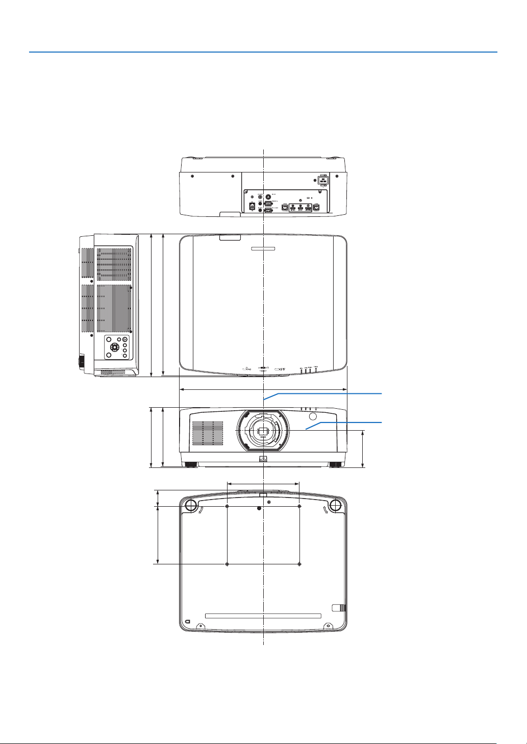
161
8. Appendix
INPUT
MENU
FOCUS SHIFT
EXIT
ZOOM
ENTER
L-CALIB.
HOME
POSITION
494 (19.4)
580 (22.8)
208 (8.2)
205 (8.1)
125 (4.9)
250 (9.8)
200 (7.9)
56.5 (2.2)
490 (19.3)
❹ Cabinet Dimensions
Lens center
Lens center
Unit: mm (inch)
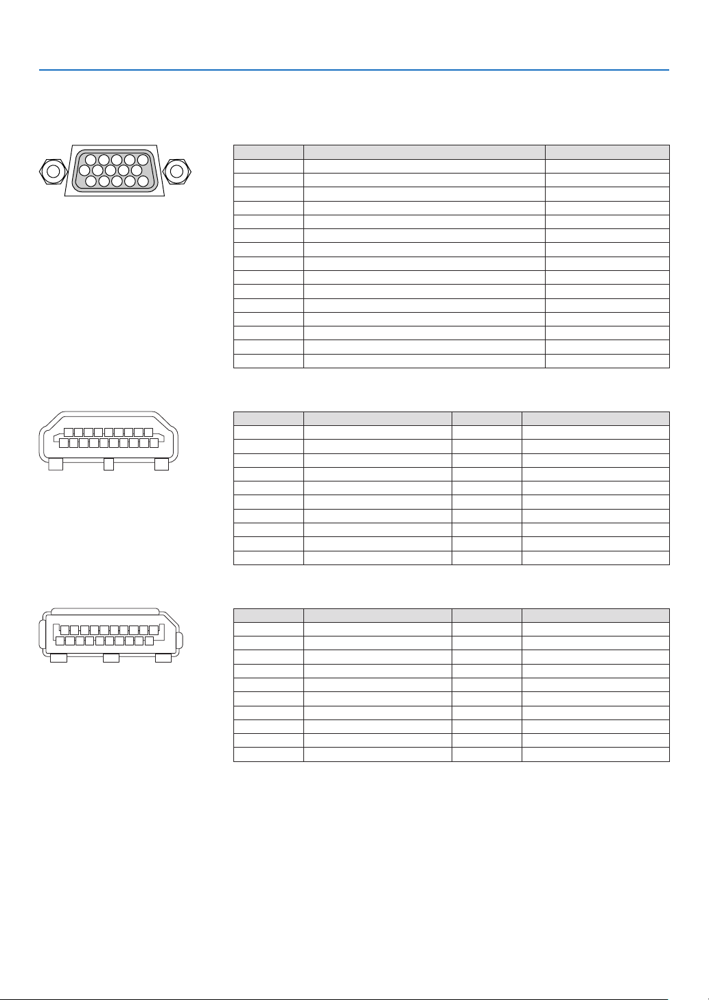
162
8. Appendix
❺ Pin assignments and signal names of main connectors
COMPUTER IN/ Component Input Connector (Mini D-Sub 15 Pin)
Connectionandsignallevelofeachpin
51423
10
11 12 13 14 15
6978
Signal Level
Videosignal:0.7Vp-p(Analog)
Syncsignal:TTLlevel
Pin No. RGBSignal(Analog)YCbCrSignal
1 RedCr
2
GreenorSynconGreenY
3 BlueCb
4 Ground
5 Ground
6
RedGroundCrGround
7 GreenGroundYGround
8 BlueGroundCbGround
9 NoConnection
10 SyncSignalGround
11 NoConnection
12 Bi-directionalDATA(SDA)
13 HorizontalSyncorCompositeSync
14 VerticalSync
15 DataClock
HDMI 1 IN/HDMI 2 IN Connector (Type A)
135791113151719
246810 12 14 16 18
Pin No. Signal Pin No. Signal
1
TMDSData2+11 TMDSClockShield
2 TMDSData2Shield12 TMDSClock−
3 TMDSData2−13 CEC
4
TMDSData1+14 Disconnection
5
TMDSData1Shield15 SCL
6
TMDSData1−16 SDA
7
TMDSData0+17 DDC/CECgrounding
8 TMDSData0Shield18 +5Vpowersupply
9 TMDSData0−19 Hotplugdetection
10 TMDSClock+
DisplayPort IN Connector
135791113151719
246810 12 14 16 18 20
Pin No. Signal Pin No. Signal
1
Mainlinklane3−11 Grounding0
2 Grounding312 Mainlinklane0+
3 Mainlinklane3+13 Conguration1
4 Mainlinklane2−14 Conguration2
5 Grounding215 Supplementarychannel+
6 Mainlinklane2+16 Grounding4
7 Mainlinklane1−17 Supplementarychannel−
8 Grounding118 Hotplugdetection
9 Mainlinklane1+19 Return
10
Mainlinklane0−20 +3.3Vpowersupply
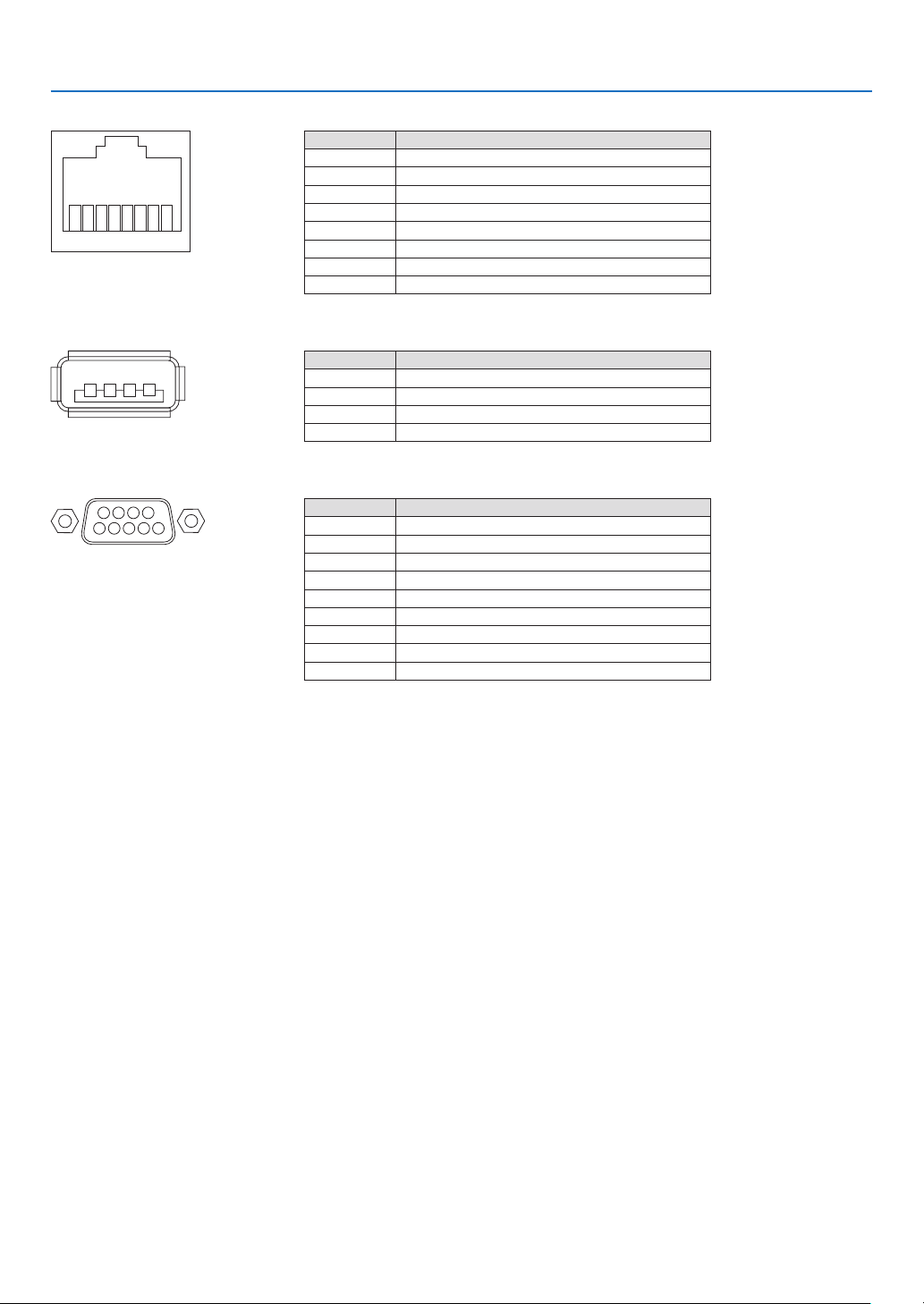
163
8. Appendix
HDBaseT IN/Ethernet Port (RJ-45)
12345678
Pin No. Signal
1 TxD+/HDBT0+
2 TxD−/HDBT0−
3 RxD+/HDBT1+
4 Disconnection/HDBT2+
5 Disconnection/HDBT2−
6 RxD−/HDBT1−
7 Disconnection/HDBT3+
8 Disconnection/HDBT3−
USB-A Port (Type A)
1
3
24
Pin No. Signal
1 V
BUS
2 D−
3 D+
4 Grounding
PC CONTROL Port (D-Sub 9 Pin)
1234
5
6789
Pin No. Signal
1 Unused
2
RxDreceptiondata
3 TxDtransmissiondata
4 Unused
5 Grounding
6 Unused
7
RTStransmissionrequest
8 CTStransmissionallowed
9 Unused
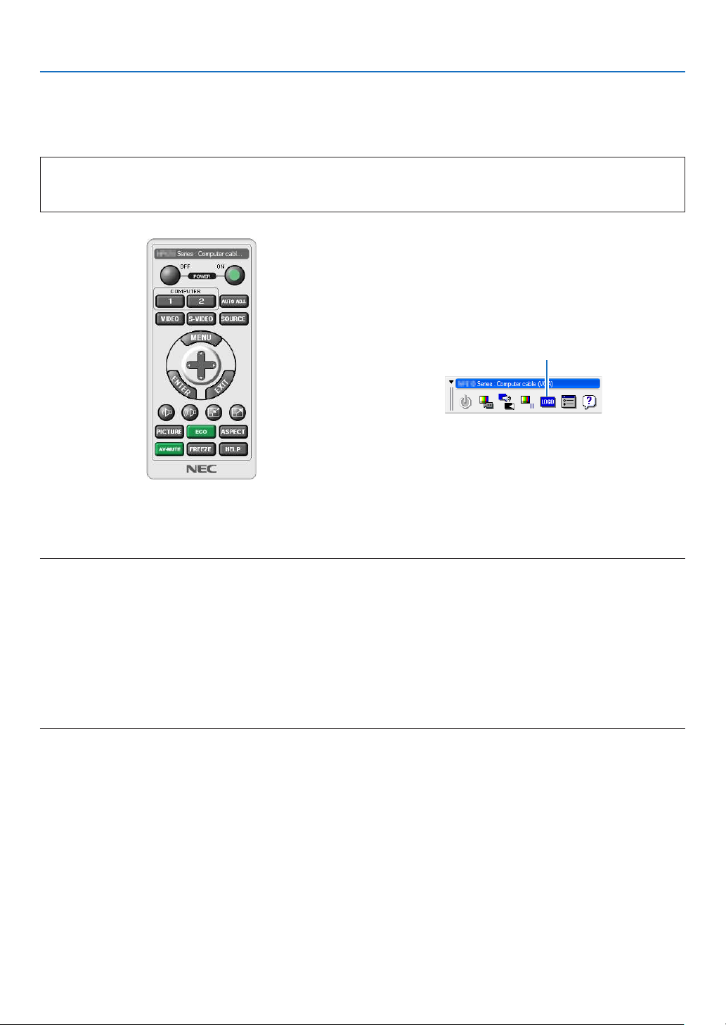
164
8. Appendix
❻ Changing the Background Logo (Virtual Remote Tool)
Thiswillhelpyouperformoperationssuchasprojector’spoweronoroffandsignalselectionviaaLANconnection.
Itisalsousedtosendanimagetotheprojectorandregisteritasthelogodataoftheprojector.Afterregisteringit,
youcanlockthelogotopreventitfromchanging.
Control Functions
PowerOn/Off,signalselection,picturefreeze,picturemute,audiomute,Logotransfertotheprojector,andremote
controloperationonyourPC.
VirtualRemotescreen
Use this button for changing
the background logo.
RemoteControlWindowToolbar
ForgettingtheVirtualRemoteTool,pleasevisitourwebsiteanddownloadit:
http://www.nec-display.com/dl/en/index.html
NOTE:
•RemoteControlWindowisnotavailableforchangingthebackgroundlogo.
PleaseseetheHELPmenuoftheVirtualRemoteToolabouthowtodisplaytheToolbar.
•Logodata(graphics)thatcanbesenttotheprojectorwithVirtualRemoteToolhasthefollowingrestrictions:
(OnlyviaserialorLANconnection)
*Filesize:Within256kilobytes
*Imagesize:Withintheresolutionoftheprojector
*Fileformat:PNG(Fullcolor)
•Logodata(image)sentusingtheVirtualRemoteToolwillbedisplayedinthecenterwiththesurroundingareainblack.
•Toputthedefault“NEClogo”backinthebackgroundlogo,youneedtoregisteritasthebackgroundlogobyusingtheimagele
(\Logo\necpj_bbwux.png)includedonthesuppliedNECProjectorCD-ROM.
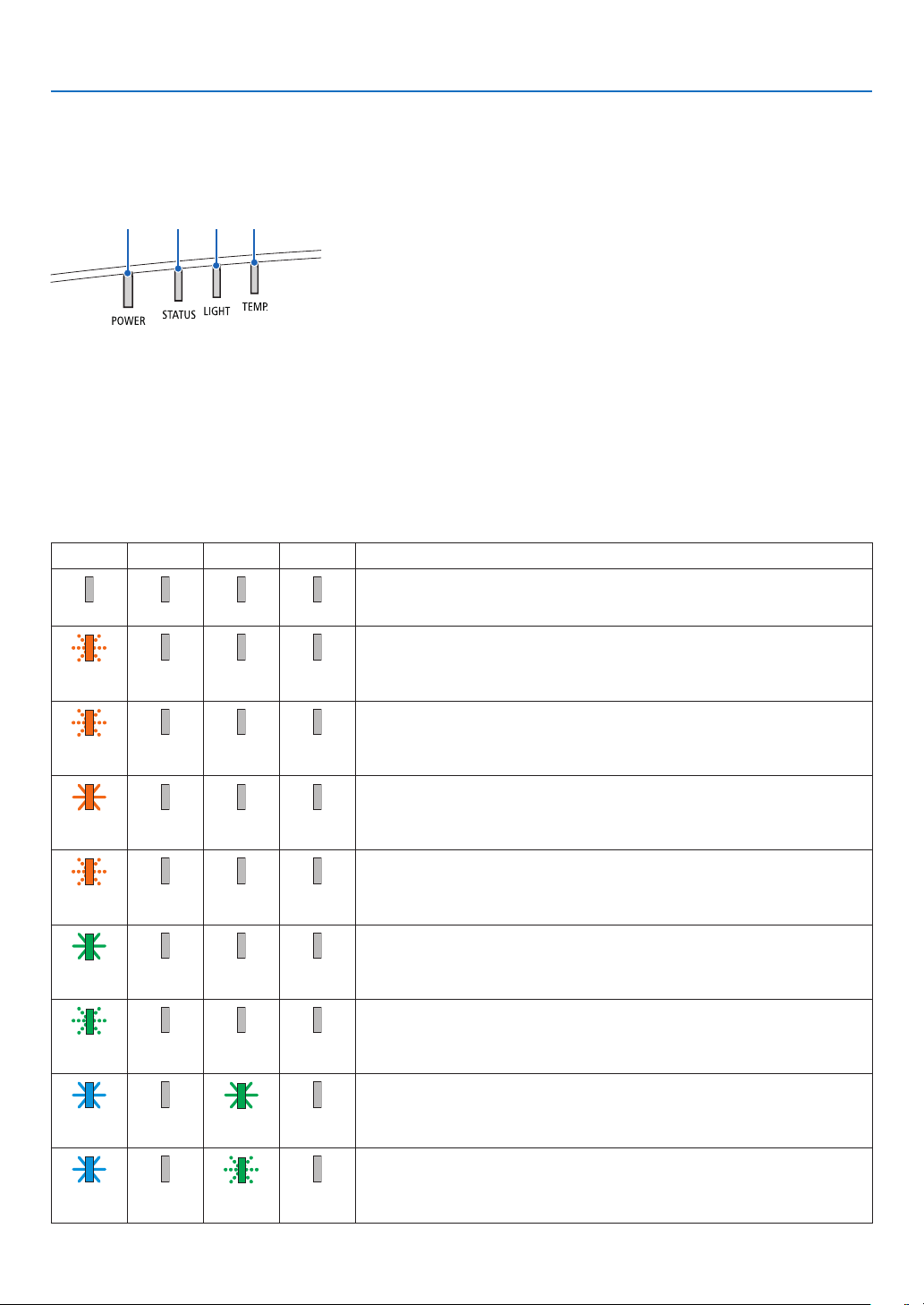
165
8. Appendix
❼ Troubleshooting
Thissectionhelpsyouresolveproblemsyoumayencounterwhilesettinguporusingtheprojector.
Feature of each indicator
②③④①
①POWERindicator
Thisindicatorinformsthepowerstatusoftheprojector.
②STATUSindicator
Thisindicatorlights/blinkswhenabuttonispressedwhiletheCONTROL
PANELLOCKfunctionisutilized,orwhileperformingthelenscalibration
andspecicoperations.
③LIGHTindicator
Thisindicatorinformsthestateoflightsource,usedtimeofthelight
source,andthestatusofLIGHTMODE.
④TEMP.indicator
Thisisthetemperatureindicatorinformingtemperaturetroublewhenthe
ambienttemperatureistoohigh/low.
Indicator Message (Status message)
POWERSTATUSLIGHTTEMP.Projector status
Power is off
Off Off Off Off
InthestateofStandby(StandbymodeisNORMALandthenetworkisready.
Orange
(Blink*
1
)
Off Off Off
InthestateofStandby(StandbymodeisNORMALandthenetworkisunavail-
able.
Orange
(Blink*
2
)
Off Off Off
InthestateofStandby(StandbymodeisNORMALandthenetworkisavail-
able)
Orange
(Light)
Off Off Off
ONtimeastheprogramtimerisactivated.(InthestateofStandby)
Orange
(Blink*
3
)
Off Off Off
InthestateofSleep
Green
(Light)
Off Off Off
ONtimeastheprogramtimerisactivated.(InthestateofSleep)
Green
(Blink*
3
)
Off Off Off
Poweredstate(LIGHTMODEisNORMALorECO1)
Blue
(Light)
Off Green
(Light)
Off
Poweredstate(LIGHTMODEisECO2orLONGLIFE)
Blue
(Light)
Off Green
(Blink*
3
)
Off
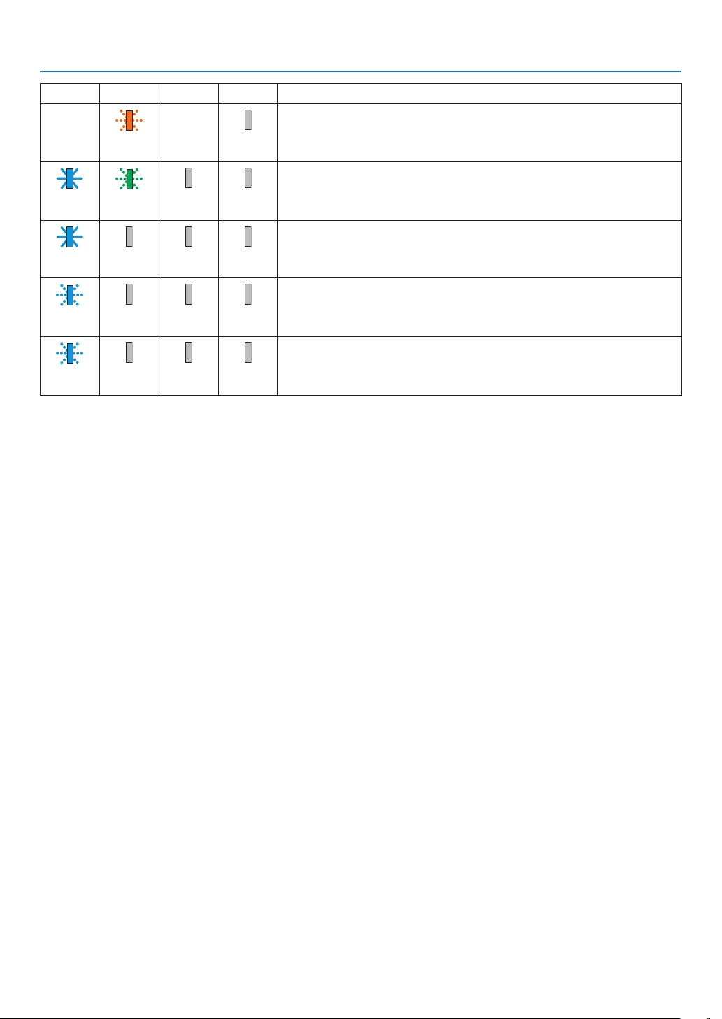
166
8. Appendix
POWERSTATUSLIGHTTEMP.Projector status
Lenscalibrationimplementrequest.
Status
varies
Orange
(Blink*
4
)
Status
varies
Off
Performingthelenscalibration
Blue
(Light)
Green
(Blink*
4
)
Status
varies
Off
Shutterfunctionisactivating
Blue
(Light)
Status
varies
Off Off
OFFTimerisactivated,OFFtimeastheproogramtimerisactivated(Powered
state)
Blue
(Blink*
3
)
Off Status
varies
Off
PreparingforpoweringON
Blue
(Blink*
5
)
Off Off Off
*1Repetitiontolightonfor1.5seconds/offfor1.5seconds
*2Repetitiontolightonfor1.5seconds/offfor7.5seconds
*3Repetitiontolightonfor2.5seconds/offfor0.5seconds
*4Repetitiontolightonfor0.5seconds/offfor0.5seconds/onfor0.5seconds/offfor2.5seconds
*5Repetitiontolightonfor0.5seconds/offfor0.5seconds
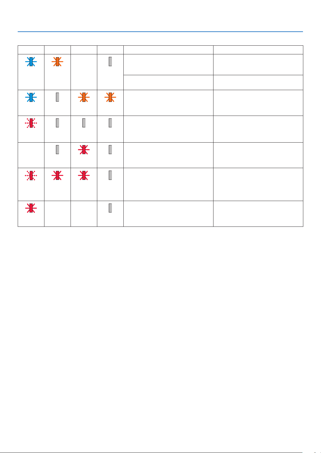
167
8. Appendix
Indicator Message (Error message)
POWERSTATUSLIGHTTEMP.Projector status Procedure
A button has been pressed while the
KEYLOCKisactivated.
Theprojector’skeysarelocked.The
settingmustbecanceledtooperate
the projector. (→page120)
Blue
(Light)
Orange
(Light)
Status
varies
Off
IDnumbersfortheprojectorandthe
remote control do not match.
CheckthecontrolIDs(→page
121)
Temperatureproblem(IntheForced
ECO)
Ambienttemtepratureishigh.Lower
the room temperature.
Blue
(Light)
Off Orange
(Light)
Orange
(Light)
TemperatureproblemAmbient temperature is out of the
operationtemperature.Checkifany
obstructionstaysneartheexhaust
vent.
Red
(Blink*
5
)
Off Off Off
HardwareproblemProblemwiththehardware.Contact
your dealer.
Status
varies
Off Red
(Blink*
5
)
Off
Lensmountingerror/LensproblemLens is not mounted properly. Mout it
(→seepage138,160).Iftheindica-
tormessageisremainunchanged
evenifthelensismountedproperly,
contact your dealer.
Red
(Blink*
5
)
Red
(Light)
Red
(Light)
Off
ErrorrequiringservicesupportContactyourdealerorserviceperson-
nel.Makesuretocheckandinform
indicatorstatusforaskingtorepair.
Red
(Light)
Status
varies
Status
varies
Off
*1Repetitiontolightonfor1.5seconds/offfor1.5seconds
*2Repetitiontolightonfor1.5seconds/offfor7.5seconds
*3Repetitiontolightonfor2.5seconds/offfor0.5seconds
*4Repetitiontolightonfor0.5seconds/offfor0.5seconds/onfor0.5seconds/offfor2.5seconds
*5Repetitiontolightonfor0.5seconds/offfor0.5seconds
•Whenthethermalprotectorisactivated:
Wheninsidetemperatureoftheprojectorbecomestoohighorlow,thePOWERindicatorstarttoredblinkinashortcycle.After
thishappened,thethermalprotectorwillactivateandtheprojectormaybeturnedoff.
Inthiscase,pleasetakethebelowmeasures:
-Pulloutthepowerplugfromthewallinlet.
-Placetheprojectorincoolplaceifithasbeenplacedinhighambienttemperature.
-Cleantheexhaustventifdusthasaccumulatedon.
-Leavetheprojectorforaboutonehouruntilinsidetemperaturegetslower.
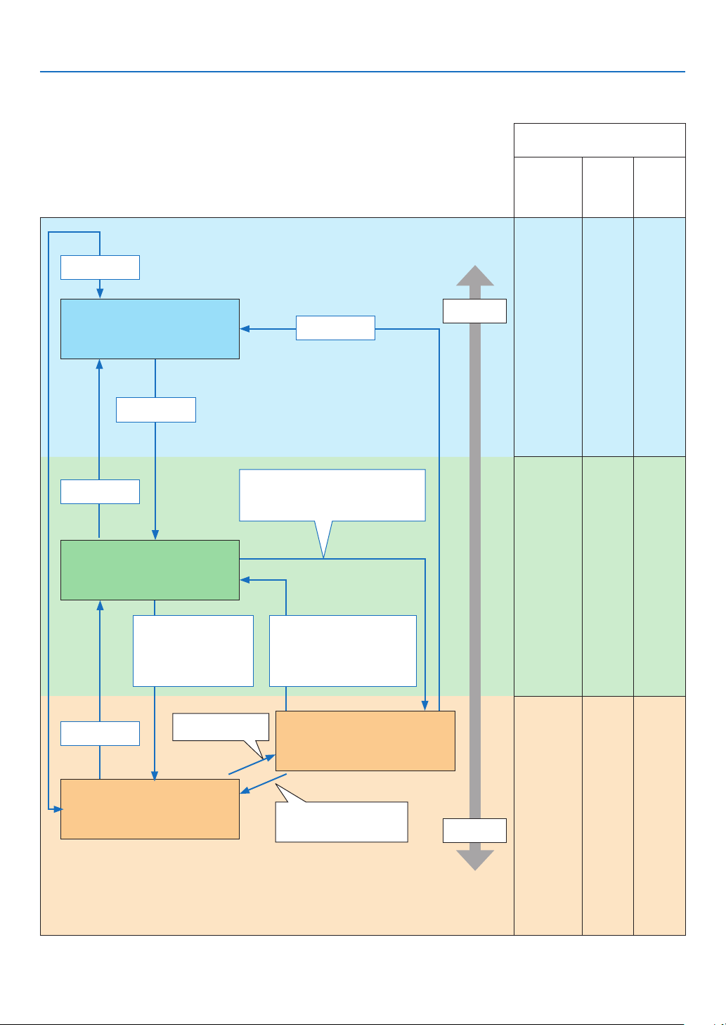
168
8. Appendix
Explanation on the POWER indicator and standby state
InthestatetheselectedPROFILEforWIREDLANisavailable.
Available ports in each state
(○: Available, ×: Unavailable)
HDBaseT IN/
Ethernet
HDBaseT OUT/
Ethernet
LAN PC CON-
TROL
○ ○ ○
○ ○ ○
× ○ ○
Indicator : Lights in blue
Powered ON state
Indicator : Lights in green
Sleep state
Indicator: Blinks in orange
Standby state: Waiting to link with the
network
Indicator: Lights in orange
Standby state: The network is linked.
Link-up network
Link-down network for approx.
10 seconds
Power
consumption
High
Low
Power On
Input signal
•Inputsignal
•Operationonthewebbrowser
via the HTTP server (→ See
page 47)
No operation / No communication with the
link-up network / No signal input for approx.
180 seconds
Power Off
Power On
Power On
No operation/Link-down
network/No signal input for
approx. 10 seconds
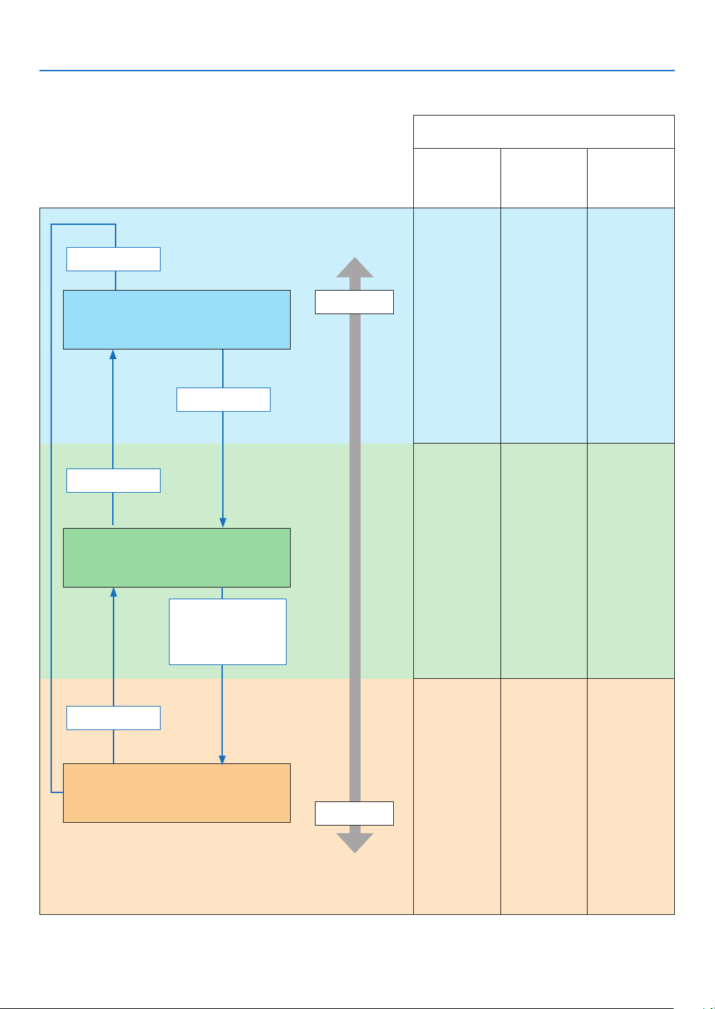
169
8. Appendix
InthestatetheselectedPROFILEforWIREDLANisunavailable.
Available ports in each state
(○: Available, ×: Unavailable)
HDBaseT IN/
Ethernet
HDBaseT OUT/
Ethernet
LAN PC CONTROL
○ × ○
○ × ○
× × ○
Indicator: Lights in blue
Powered ON state
Indicator: Lights in green
Sleep state
Indicator: Blinks in orange (with long interval)
Standby state: The network is unavailable.
Power consumption
High
Low
Power On
Input signal
Power Off
Power On
No operation / No signal in-
put for approx. 10 seconds

170
8. Appendix
Common Problems & Solutions
(→“IndicatorMessage”onpage
165.)
Problem Check These Items
Does not turn on
or shut down
• Checkthatthepowercordispluggedinandthatthepowerbuttonontheprojectorcabinetortheremotecontrol
is on. (→ pages
14, 16)
• Checktoseeiftheprojectorhastemperatureerror,Ifprojectorinsidetemperatureistoohotorcool,itdisabledto
turn on the projector as the protection. Wait for a moment and try turn on the projector again.
• Set[FANMODE]to[HIGHALTITUDE]whenusingtheprojectorataltitudesapproximately5500feet/1700meters
or higher. Using the projector at altitudes approximately 5500 feet/1700 meters or higher without setting to [HIGH
ALTITUDE] can cause the projector to overheat and the projector could shut down. If this happens, wait a couple
minutes and turn on the projector. (→ page 112)
If you turn on the projector immediately after the light module is turned off, the fans run without displaying an image
for some time and then the projector will display the image. Wait for a moment.
• Incaseit’shardtothinkthetroubleisnotcausedontheabovementionedconditions,unplugthepowercordfrom
the outlet. Then wait 5 minutes before plugging it in again. (→ page 28, 29)
Will turn off
• Ensurethatthe[OFFTIMER],[AUTOPOWEROFF]or[PROGRAMTIMER]isoff.(→ page
117, 131)
No picture
• Checkiftheappropriateinputisselected.(→ page
18) If there is still no picture, press the INPUT button or one of
the input buttons again.
• Ensureyourcablesareconnectedproperly.
• Usemenustoadjustthebrightnessandcontrast.(→ page 88)
• Isthe[POWERONSHUTTER]intheon-screenmenusetto[CLOSE]?
• CheckthattheSHUTTER(lensshutter)orAV-MUTE(imageoff)buttonsarenotpressed.
• Resetthesettingsoradjustmentstofactorypresetlevelsusingthe[RESET]intheMenu.(→ page 132)
• EnteryourregisteredkeywordiftheSecurityfunctionisenabled.(→ page 41)
• IftheHDMIinputortheDisplayPortsignalcannotbedisplayed,trythefollowing.
- Reinstall your driver for the graphics card built in your computer, or use the updated driver.
For reinstalling or updating your driver, refer to the user guide accompanied with your computer or graphics
card, or contact the support center for your computer manufacturer.
Install the updated driver or OS on your own responsibility.
We are not liable for any trouble and failure caused by this installation.
• ThesignalmaynotbesupporteddependingontheHDBaseTtransmissiondevice.Inaddition,RS232Cinterface
may not be supported.
• BesuretoconnecttheprojectorandnotebookPCwhiletheprojectorisinstandbymodeandbeforeturningonthe
power to the notebook PC.
In most cases the output signal from the notebook PC is not turned on unless connected to the projector before
being powered up.
* If the screen goes blank while using your remote control, it may be the result of the computer’s screen-saver or
power management software.
• Seealsothepage172.
Picture suddenly
becomes dark
• CheckiftheprojectorisintheForcedECOmodebecauseoftoohighambienttemperature.Ifthisisthecase,lower
the internal temperature of the projector by selecting [HIGH] for [FAN MODE]. (→ page
112)
Color tone or hue is
unusual
• Checkifanappropriatecolorisselectedin[WALLCOLOR].Ifso,selectanappropriateoption.(→ page
112)
• Adjust[HUE]in[PICTURE].(→ page 89)
Image isn’t square to
the screen
• Repositiontheprojectortoimproveitsangletothescreen.(→ page
20)
• Perform[GEOMETRICCORRECTION]whenthetrapezoidisdistorted.(→ page 101)
Picture is blurred
• Adjustthefocus.(→ page
22)
• Repositiontheprojectortoimproveitsangletothescreen.(→ page 20)
•Ensurethatthedistancebetweentheprojectorandscreeniswithintheadjustmentrangeofthelens.
(→ page
152)
• Hasthelensbeenshiftedbyanamountexceedingtheguaranteedrange?(→ page
153)
• Condensationmayformonthelensiftheprojectoriscold,broughtintoawarmplaceandisthenturnedon.Should
this happen, let the projector stand until there is no condensation on the lens.
Flicker appears on
screen
• Set[FANMODE]tootherthan[HIGHALTITUDE]modewhenusingtheprojectorataltitudesapproximately5500
feet/1700 meters or lower. Using the projector at altitudes less than approximately 5500 feet/1700 meters and set-
ting to [HIGH ALTITUDE] can cause the light module to overcool, causing the image to flicker. Switch [FAN MODE]
to [AUTO]. (→ page
112)
Image is scrolling
vertically, horizontally
or both
• Checkthecomputer’sresolutionandfrequency.Makesurethattheresolutionyouaretryingtodisplayissupported
by the projector. (→ page
155)
• AdjustthecomputerimagemanuallywiththeHorizontal/Verticalinthe[IMAGEOPTIONS].(→ page 91)
Remote control does
not work
• Installnewbatteries.(→ page
11)
• Makesuretherearenoobstaclesbetweenyouandtheprojector.
• Standwithin40m/1575inchoftheprojector.(→ page 12)

171
8. Appendix
Problem Check These Items
Indicator is lit or
blinking
• SeetheIndicatorMessage.(→ page
165)
Cross color in RGB
mode
• PresstheAUTOADJ.buttonontheprojectorcabinetortheremotecontrol.(→ page
27)
• Adjustthecomputerimagemanuallywith[CLOCK]/[PHASE]in[IMAGEOPTIONS]inthemenu.(→ page 90)
Formoreinformationcontactyourdealer.

172
8. Appendix
If there is no picture, or the picture is not displayed correctly.
•PoweronprocessfortheprojectorandthePC.
BesuretoconnecttheprojectorandnotebookPCwhiletheprojectorisinstandbymodeandbeforeturningon
thepowertothenotebookPC.
InmostcasestheoutputsignalfromthenotebookPCisnotturnedonunlessconnectedtotheprojectorbefore
beingpoweredup.
NOTE:Youcancheckthehorizontalfrequencyofthecurrentsignalintheprojector’smenuunderInformation.Ifitreads“0kHz”,
thismeansthereisnosignalbeingoutputfromthecomputer.(→page
134orgotonextstep)
•Enablingthecomputer’sexternaldisplay.
DisplayinganimageonthenotebookPC’sscreendoesnotnecessarilymeanitoutputsasignaltotheprojector.
WhenusingaPCcompatiblelaptop,acombinationoffunctionkeyswillenable/disabletheexternaldisplay.Usu-
ally,thecombinationofthe“Fn”keyalongwithoneofthe12functionkeysgetstheexternaldisplaytocomeon
oroff.Forexample,NEClaptopsuseFn+F3,whileDelllaptopsuseFn+F8keycombinationstotogglethrough
externaldisplayselections.
•Non-standardsignaloutputfromthecomputer
IftheoutputsignalfromanotebookPCisnotanindustrystandard,theprojectedimagemaynotbedisplayed
correctly.Shouldthishappen,deactivatethenotebookPC’sLCDscreenwhentheprojectordisplayisinuse.Each
notebookPChasadifferentwayofdeactivate/reactivatethelocalLCDscreensasdescribedinthepreviousstep.
Refertoyourcomputer’sdocumentationfordetailedinformation.
•ImagedisplayedisincorrectwhenusingaMac
WhenusingaMacwiththeprojector,settheDIPswitchoftheMacadapter(notsuppliedwiththeprojector)ac-
cordingtoyourresolution.Aftersetting,restartyourMacforthechangestotakeaffect.
ForsettingdisplaymodesotherthanthosesupportedbyyourMacandtheprojector,changingtheDIPswitchon
aMacadaptermaybounceanimageslightlyormaydisplaynothing.Shouldthishappen,settheDIPswitchto
the13"xedmodeandthenrestartyourMac.Afterthat,restoretheDIPswitchestoadisplayablemodeandthen
restarttheMacagain.
NOTE:AVideoAdaptercablemanufacturedbyAppleComputerisneededforaMacBookwhichdoesnothaveaminiD-Sub
15-pinconnector.
•MirroringonaMacBook
*WhenusingtheprojectorwithaMacBook,outputmaynotbesetto1920×1200unless“mirroring”isoffonyour
MacBook.Refertoowner’smanualsuppliedwithyourMaccomputerformirroring.
•FoldersoriconsarehiddenontheMacscreen
Foldersoriconsmaynotbeseenonthescreen.Shouldthishappen,select[View]→[Arrange]fromtheApple
menuandarrangeicons.
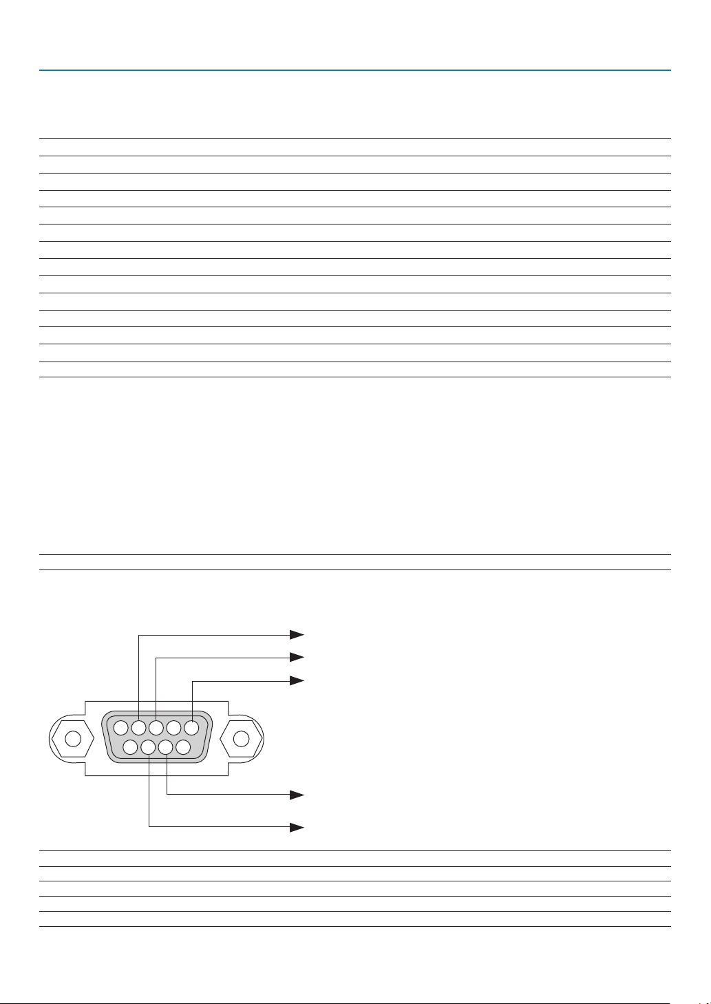
173
8. Appendix
❽ PC Control Codes and Cable Connection
PC Control Codes
Function Code Data
POWER ON 02H 00H 00H 00H 00H 02H
POWER OFF 02H 01H 00H 00H 00H 03H
INPUT SELECT HDMI1 02H 03H 00H 00H 02H 01H A1H A9H
INPUT SELECT HDMI2 02H 03H 00H 00H 02H 01H A2H AAH
INPUT SELECT DisplayPort 02H 03H 00H 00H 02H 01H A6H AEH
INPUT SELECT COMPUTER 02H 03H 00H 00H 02H 01H 01H 09H
INPUT SELECT HDBaseT 02H 03H 00H 00H 02H 01H BFH C7H
PICTURE MUTE ON 02H 10H 00H 00H 00H 12H
PICTURE MUTE OFF 02H 11H 00H 00H 00H 13H
SOUND MUTE ON 02H 12H 00H 00H 00H 14H
SOUND MUTE OFF 02H 13H 00H 00H 00H 15H
NOTE:ContactyourlocaldealerforafulllistofthePCControlCodesifneeded.
Cable Connection
CommunicationProtocol
Baud rate .........................................115200/38400/19200/9600/4800 bps
Data length ......................................8 bits
Parity ...............................................No parity
Stop bit ............................................1 bit
X on/off ............................................None
Communications procedure .............Full duplex
NOTE:Dependingontheequipment,alowerbaudratemayberecommendedforlongcableruns.
PC Control Port (D-SUB 9P)
15243
67 98
To GND of PC
To RxD of PC
To TxD of PC
To RTS of PC
To CTS of PC
NOTE1:Pins1,4,6and9arenoused.
NOTE2:Jumper“RequesttoSend”and“CleartoSend”togetheronbothendsofthecabletosimplifycableconnection.
NOTE3:Forlongcablerunsitisrecommendedtosetcommunicationspeedwithinprojectormenusto9600bps.

174
8. Appendix
ABOUT THE ASCII CONTROL COMMAND
ThisdevicesupportsthecommonASCIIControlCommandforcontrollingourprojectorandmonitor.
Please visit our web site for detailed information about the command.
http://www.nec-display.com/dl/en/pj_manual/lineup.html
HOWTOCONNECTWITHANEXTERNALDEVICE
Therearetwomethodstoconnecttheprojectorwithanexternaldevicesuchasacomputer.
1.Connectionthrutheserialport.
Connectstheprojectortoacomputerbyaserialcable(acrosscable).
2. Connectionvianetwork(LAN/HDBaseT)
ConnectstheprojectortoacomputerbyaLANcable.
ConcerningtothetypeofLANcable,pleaseasktoyournetworkadministrator.
CONNECTION INTERFACE
1.Connectionthrutheserialport.
CommunicationProtocol
ItemInformation
Baudrate115200/38400/19200/9600/4800 bps
Datalength8 bits
Parity bit No parity
Stopbit1 bit
FlowcontrolNone
CommunicationsprocedureFullduplex
2. Connectionvianetwork
CommunicationProtocol(ConnectionviaLAN)
ItemInformation
CommunicationspeedSetautomatically(10/100Mbps)
SupportedstandardIEEE802.3(10BASE-T)
IEEE802.3u(100BASE-TX,Auto-Negotiation)
UsetheTCPportnumber7142fortransmittingandreceivingcommand.
CommunicationProtocol(ConnectionviaHDBaseT)
ItemInformation
Communicationspeed100 Mbps
SupportedstandardIEEE802.3u(100BASE-TX,Auto-Negotiation)
UsetheTCPportnumber7142fortransmittingandreceivingcommand.
PARAMETERSFORTHISDEVICE
Input command
InputterminalResponseParameter
HDMI1hdmi1 hdmi1 or hdmi
HDMI2hdmi2 hdmi2
DisplayPortdisplayport displayport or displayport1
COMPUTERcomputer
Oneamongcomputer,computer1,vga,vga1,rgb,andrgb1
HDBaseThdbaset hdbaset or hdbaset1

175
8. Appendix
Status command
ResponseErrorStatus
error:temp Temperatureerror
error:fan Fantrouble
error:lightLightsourcetrouble
error:lens Lens trouble
error:system
Systemtrouble

176
8. Appendix
❾ Troubleshooting Check List
Beforecontactingyourdealerorservicepersonnel,checkthefollowinglisttobesurerepairsareneededalsoby
referringtothe“Troubleshooting”sectioninyouruser’smanual.Thischecklistbelowwillhelpussolveyourproblem
more efficiently.
*Printthispageandthenextpageforyourcheck.
Frequency of occurrence □ always □sometimes(Howoften?_____________________)□other(__________________)
Power
□
No power (POWER indicator does not light blue). See also “Status
Indicator (STATUS)”.
□
Power cord’s plug is fully inserted into the wall outlet.
□
No power even though you press and hold the POWER button.
□
Shut down during operation.
□
Power cord’s plug is fully inserted into the wall outlet.
□
[AUTO POWER OFF] is turned off (only models with the [AUTO
POWER OFF] function).
□
[OFF TIMER] is turned off (only models with the [OFF TIMER]
function).
Video and Audio
□
No image is displayed from your PC or video equipment to the
projector.
□
Still no image even though you connect the projector to the PC
first, then start the PC.
□
Enabling your notebook PC’s signal output to the projector.
• Acombinationoffunctionkeyswillenable/disabletheexter-
naldisplay.Usually,thecombinationofthe“Fn”keyalong
withoneofthe12functionkeysturnstheexternaldisplay
onoroff.
□
No image (blue or black background, no display).
□
Still no image even though you press the AUTO ADJ. button.
□
Still no image even though you carry out [RESET] in the
projector’s menu.
□
Signal cable’s plug is fully inserted into the input connector
□
A message appears on the screen.
(_____________________________________________)
□
The source connected to the projector is active and available.
□
Still no image even though you adjust the brightness and/or
the contrast.
□
Input source’s resolution and frequency are supported by the
projector.
□
Image is too dark.
□
Remains unchanged even though you adjust the brightness
and/or the contrast.
□
Image is distorted.
□
Image appears to be trapezoidal (unchanged even though you
carry out the [KEYSTONE] adjustment).
□
Parts of the image are lost.
□
Still unchanged even though you press the AUTO ADJ. button.
□
Still unchanged even though you carry out [RESET] in the
projector’s menu.
□
Image is shifted in the vertical or horizontal direction.
□
Horizontal and vertical positions are correctly adjusted on a
computer signal.
□
Input source’s resolution and frequency are supported by the
projector.
□
Some pixels are lost.
□
Image is flickering.
□
Still unchanged even though you press the AUTO ADJ. button.
□
Still unchanged even though you carry out [RESET] in the
projector’s menu.
□
Image shows flickering or color drift on a computer signal.
□
Still unchanged even though you change [FAN MODE] from
[HIGH ALTITUDE] to [AUTO].
□
Image appears blurry or out of focus.
□
Still unchanged even though you checked the signal’s resolution
on PC and changed it to projector’s native resolution.
□
Still unchanged even though you adjusted the focus.
□
No sound.
□
Audio cable is correctly connected to the audio input of the
projector.
□
Still unchanged even though you adjusted the volume level.
□
AUDIO OUT is connected to your audio equipment (only models
with the AUDIO OUT connector).
Other
□
Remote control does not work.
□
No obstacles between the sensor of the projector and the
remote control.
□
Projector is placed near a fluorescent light that can disturb the
infrared remote controls.
□
Batteries are new and are not reversed in installation.
□
Buttons on the projector cabinet do not work (only models with the
[CONTROL PANEL LOCK] function)
□
[CONTROL PANEL LOCK] is not turned on or is disabled in
the menu.
□
Still unchanged even though you press and hold the INPUT
button for a minimum of 10 seconds.
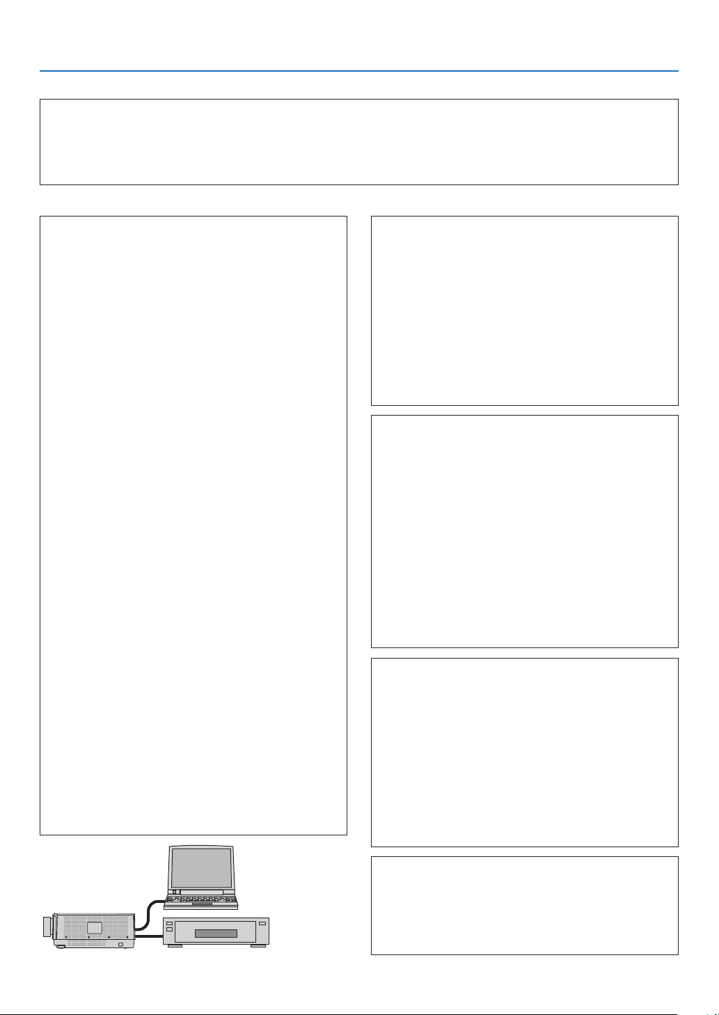
177
8. Appendix
In the space below please describe your problem in detail.
Information on application and environment where your projector is used
Installation environment
Screen size: inch
Screen type: □ White matte □ Beads □ Polarization
□ Wide angle □ High contrast
Throw distance: feet/inch/m
Orientation: □ Ceiling mount □ Desktop
Power outlet connection:
□
Connected directly to wall outlet
□ Connected to power cord extender or other (the
numberofconnectedequipment______________)
□ Connected to a power cord reel or other (the number
ofconnectedequipment______________)
Computer
Manufacturer:
Model number:
Notebook PC □ / Desktop □
Native resolution:
Refresh rate:
Video adapter:
Other:
Videoequipment
VCR, Blu-ray player, Video camera, Video game or other
Manufacturer:
Model number:
Signal cable
NECstandardorothermanufacturer’scable?
Model number: Length: inch/m
Distribution amplifier
Model number:
Switcher
Model number:
Adapter
Model number:
Projector
PC
Blu-ray player
Projector
Model number:
Serial No.:
Date of purchase:
Light operating time (hours):
LIGHT MODE: □ NORMAL □ ECO1
□ ECO2 □ LONG LIFE
Information on input signal:
Horizontal synch frequency [ ] kHz
Vertical synch frequency [ ] Hz
Synch polarity H □ (+) □ (−)
V □ (+) □ (−)
Synch type □ Separate □ Composite
□ Sync on Green
Indicator Message:
□ POWER
Blinks in □ Blue □ Green □ Orange □ Red
[ ] cycles
Lights in □ Blue □ Green □ Orange □ Red
□ STATUS
Blinks in □ Blue □ Green □ Orange □ Red
[ ] cycles
Lights in □ Blue □ Green □ Orange □ Red
□ LIGHT
Blinks in □ Blue □ Green □ Orange □ Red
[ ] cycles
Lights in □ Blue □ Green □ Orange □ Red
□ TEMP.
Blinks in □ Blue □ Green □ Orange □ Red
[ ] cycles
Lights in □ Blue □ Green □ Orange □ Red
Remote control model number:

178
8. Appendix
❿ REGISTER YOUR PROJECTOR! (for residents in the United
States, Canada, and Mexico)
Pleasetaketimetoregisteryournewprojector.ThiswillactivateyourlimitedpartsandlaborwarrantyandInstaCare
serviceprogram.
Visit our web site at
www.necdisplay.com,clickonsupportcenter/registerproductandsubmityourcompletedform
online.
Uponreceipt,wewillsendaconrmationletterwithallthedetailsyouwillneedtotakeadvantageoffast,reliable
warrantyandserviceprogramsfromtheindustryleader,NECDisplaySolutionsofAmerica,Inc.

©NECDisplaySolutions,Ltd.20177N952581
