Projector
PA622U/PA522U
PA672W/PA572W
PA722X/PA622X
User’s Manual
Model No.
NP-PA622U/NP-PA522U/NP-PA672W/NP-PA572W/NP-PA722X/
NP-PA622X

Ver. 1 1/2014
• Apple,Mac,MacOS,andMacBookaretrademarksofAppleInc.registeredintheU.S.andothercountries.
• Microsoft,Windows,WindowsVista,InternetExplorer,.NETFrameworkandPowerPointareeitheraregistered
trademarkortrademarkofMicrosoftCorporationintheUnitedStatesand/orothercountries.
• MicroSaverisaregisteredtrademarkofKensingtonComputerProductsGroup,adivisionofACCOBrands.
• Adobe,AdobePDF,AdobeReader,andAcrobatareeitherregisteredtrademarksortrademarksofAdobeSystems
IncorporatedintheUnitedStatesand/orothercountries.
• VirtualRemoteToolusesWinI2C/DDClibrary,©NicomsoftLtd.
• HDMI,theHDMILogoandHigh-DenitionMultimediaInterfacearetrademarksorregisteredtrademarksofHDMI
LicensingLLC.
• DisplayPortandDisplayPortComplianceLogoaretrademarksownedbytheVideoElectronicsStandardsAssocia-
tion.
• TrademarkPJLinkisatrademarkappliedfortrademarkrightsinJapan,theUnitedStatesofAmericaandother
countriesandareas.
• Wi-Fi
®
,Wi-FiAlliance
®
,andWi-FiProtected Access(WPA,WPA2)
®
areregistered trademarks of theWi-FiAlli-
ance.
• Blu-rayisatrademarkofBlu-rayDiscAssociation
• CRESTRONandROOMVIEWareregisteredtrademarksofCrestronElectronics,Inc.intheUnitedStatesandother
countries.
• Otherproductandcompanynamesmentionedinthisuser’smanualmaybethetrademarksorregisteredtrademarks
oftheirrespectiveholders.
NOTES
(1)Thecontentsofthisuser’smanualmaynotbereprintedinpartorwholewithoutpermission.
(2)Thecontentsofthisuser’smanualaresubjecttochangewithoutnotice.
(3)Greatcarehasbeentakeninthepreparationofthisuser’smanual;however,shouldyounoticeanyquestionable
points,errorsoromissions,pleasecontactus.
(4)Notwithstandingarticle(3),NECwillnotberesponsibleforanyclaimsonlossofprotorothermattersdeemed
toresultfromusingtheProjector.
i
Important Information
Safety Cautions
Precautions
PleasereadthismanualcarefullybeforeusingyourNECprojectorandkeepthemanualhandyforfuturereference.
CAUTION
Toturnoffmainpower,besuretoremovetheplugfrompoweroutlet.
Thepoweroutletsocketshouldbeinstalledasneartotheequipmentaspossible,andshouldbeeasily
accessible.
CAUTION
TOPREVENTSHOCK,DONOTOPENTHECABINET.
THEREAREHIGH-VOLTAGECOMPONENTSINSIDE.
REFERSERVICINGTOQUALIFIEDSERVICEPERSONNEL.
Thissymbolwarnstheuserthatuninsulatedvoltagewithintheunitmaybesufcienttocauseelectrical
shock.Therefore,itisdangeroustomakeanykindofcontactwithanypartinsideoftheunit.
Thissymbolalertstheuserthatimportantinformationconcerningtheoperationandmaintenanceofthis
unithasbeenprovided.
Theinformationshouldbereadcarefullytoavoidproblems.
WARNING:TOPREVENTFIREORSHOCK,DONOTEXPOSETHISUNITTORAINORMOISTURE.
DONOTUSETHISUNIT’SPLUGWITHANEXTENSIONCORDORINANOUTLETUNLESSALLTHEPRONGS
CANBEFULLYINSERTED.
DOC Compliance Notice (for Canada only)
ThisClassBdigitalapparatuscomplieswithCanadianICES-003.
Machine Noise Information Regulation - 3. GPSGV,
Thehighestsoundpressurelevelislessthan70dB(A)inaccordancewithENISO7779.
CAUTION
Avoiddisplayingstationaryimagesforaprolongedperiodoftime.
DoingsocanresultintheseimagesbeingtemporarilysustainedonthesurfaceoftheLCDpanel.
Ifthisshouldhappen,continuetouseyourprojector.Thestaticbackgroundfrompreviousimageswill
disappear.
Disposing of your used product
EU-widelegislationasimplementedineachMemberStaterequiresthatusedelectricalandelectronicprod-
uctscarryingthemark(left)mustbedisposedofseparatelyfromnormalhouseholdwaste.Thisincludes
projectorsandtheirelectricalaccessoriesorlamps.Whenyoudisposeofsuchproducts,pleasefollowthe
guidanceofyourlocalauthorityand/orasktheshopwhereyoupurchasedtheproduct.
Aftercollectingtheusedproducts,theyarereusedandrecycledinaproperway.Thiseffortwillhelpus
reducethewastesaswellasthenegativeimpactsuchasmercurycontainedinalamptothehumanhealth
andtheenvironmentattheminimumlevel.
ThemarkontheelectricalandelectronicproductsonlyappliestothecurrentEuropeanUnionMember
States.

ii
Important Information
WARNING TO CALIFORNIA RESIDENTS:
Handlingthecablessuppliedwiththisproductwillexposeyoutolead,achemicalknowntotheStateofCalifornia
tocausebirthdefectsorotherreproductiveharm.WASHHANDSAFTERHANDLING.
RF Interference (for USA only)
WARNING
TheFederalCommunicationsCommissiondoesnotallowanymodicationsorchangestotheunitEXCEPTthose
speciedbyNECDisplaySolutionsofAmerica,Inc.inthismanual.Failuretocomplywiththisgovernmentregu-
lationcouldvoidyourrighttooperatethisequipment.Thisequipmenthasbeentestedandfoundtocomplywith
thelimitsforaClassBdigitaldevice,pursuanttoPart15oftheFCCRules.Theselimitsaredesignedtoprovide
reasonableprotectionagainstharmfulinterferenceinaresidentialinstallation.Thisequipmentgenerates,uses,and
canradiateradiofrequencyenergyand,ifnotinstalledandusedinaccordancewiththeinstructions,maycause
harmfulinterferencetoradiocommunications.However,thereisnoguaranteethatinterferencewillnotoccurina
particularinstallation.
Ifthisequipmentdoescauseharmfulinterferencetoradioortelevisionreception,whichcanbedeterminedby
turningtheequipmentoffandon,theuserisencouragedtotrytocorrecttheinterferencebyoneormoreofthe
followingmeasures:
• Reorientorrelocatethereceivingantenna.
• Increasetheseparationbetweentheequipmentandreceiver.
• Connecttheequipmentintoanoutletonacircuitdifferentfromthattowhichthereceiverisconnected.
• Consultthedealeroranexperiencedradio/TVtechnicianforhelp.
ForUKonly:InUK,aBSapprovedpowercordwithmouldedplughasaBlack(veAmps)fuseinstalledforusewith
thisequipment.Ifapowercordisnotsuppliedwiththisequipmentpleasecontactyoursupplier.
Important Safeguards
Thesesafetyinstructionsaretoensurethelonglifeofyourprojectorandtopreventreandshock.Pleasereadthem
carefullyandheedallwarnings.
Installation
• Donotplacetheprojectorinthefollowingconditions:
- onanunstablecart,stand,ortable.
- nearwater,baths,ordamprooms.
- indirectsunlight,nearheaters,orheatradiatingappliances.
- inadusty,smokyorsteamyenvironment.
- onasheetofpaperorcloth,rugsorcarpets.
• Ifyouwishtohavetheprojectorinstalledontheceiling:
- Donotattempttoinstalltheprojectoryourself.
- Theprojectormustbeinstalledbyqualiedtechniciansinordertoensureproperoperationandreducetherisk
ofbodilyinjury.
- Inaddition,theceilingmustbestrongenoughtosupporttheprojectorandtheinstallationmustbeinaccordance
withanylocalbuildingcodes.
- Pleaseconsultyourdealerformoreinformation.
iii
Important Information
WARNING
• Donotcoverthelenswiththelenscaporequivalentwhiletheprojectorison.Doingsocanleadtomeltingof
thecapduetotheheatemittedfromthelightoutput.
• Donotplaceanyobjects,whichareeasilyaffectedbyheat,infrontoftheprojectorlens.Doingsocouldlead
totheobjectmeltingfromtheheatthatisemittedfromthelightoutput.
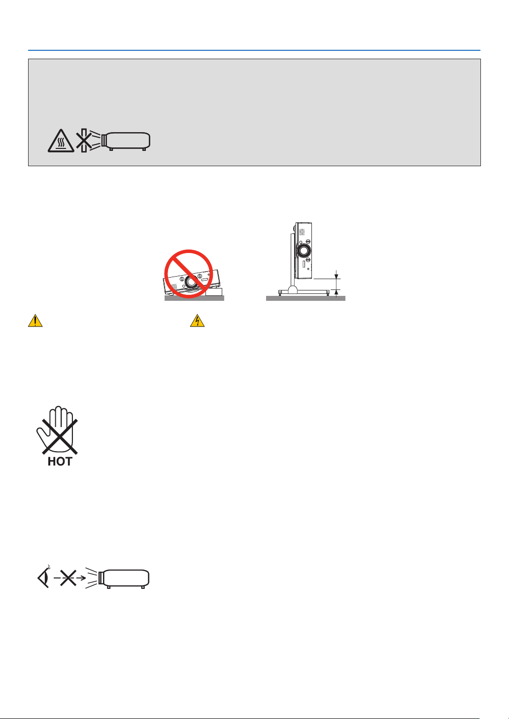
Donotusetheprojectorwithitleaningtotheleftandright.Thismayresultinamalfunction.However,portraitinstal-
lationispossible*(whenacustom-designedstandismade).Forportraitinstallation,installtheprojectorwiththeair
intakeatthebottomandleaveaspaceofatleast130mmbelowtheairintake.
130 mm or more
Fire and Shock Precautions
• Ensurethatthereissufcientventilationandthatventsareunobstructedtopreventthebuild-upofheatinsideyour
projector.Allowenoughspacebetweenyourprojectorandawall.(→pagevii)
• Donottrytotouchtheventilationoutletontheleftfront(whenseenfromthefront)asitcanbecomeheatedwhile
theprojectoristurnedonandimmediatelyaftertheprojectoristurnedoff.Partsoftheprojectormaybecometem-
porarilyheatediftheprojectoristurnedoffwiththePOWERbuttonoriftheACpowersupplyisdisconnectedduring
normalprojectoroperation.
Usecautionwhenpickinguptheprojector.
• Preventforeignobjectssuchaspaperclipsandbitsofpaperfromfallingintoyourprojector.Donotattempttoretrieve
anyobjectsthatmightfallintoyourprojector.Donotinsertanymetalobjectssuchasawireorscrewdriverintoyour
projector.Ifsomethingshouldfallintoyourprojector,disconnectitimmediatelyandhavetheobjectremovedbya
qualiedservicepersonnel.
• Donotplaceanyobjectsontopoftheprojector.
• Donottouchthepowerplugduringathunderstorm.Doingsocancauseelectricalshockorre.
• Theprojectorisdesignedtooperateonapowersupplyof100-240VAC50/60Hz.Ensurethatyourpowersupply
tsthisrequirementbeforeattemptingtouseyourprojector.
• Donotlookintothelenswhiletheprojectorison.Seriousdamagetoyoureyescouldresult.
• Keepanyitems(magnifyingglassetc.)outofthelightpathoftheprojector.Thelightpathbeingprojectedfromthe
lensisextensive,thereforeanykindofabnormalobjectsthatcanredirectlightcomingoutofthelens,cancause
anunpredictableoutcomesuchasareorinjurytotheeyes.
• Donotplaceanyobjects,whichareeasilyaffectedbyheat,infrontofaprojectorexhaustvent.
Doingsocouldleadtotheobjectmeltingorgettingyourhandsburnedfromtheheatthatisemittedfromtheex-
haust.

iv
Important Information
• Handlethepowercordcarefully.Adamagedorfrayedpowercordcancauseelectricshockorre.
- Donotuseanypowercordotherthantheonesuppliedwiththeprojector.
- Donotbendortugthepowercordexcessively.
- Donotplacethepowercordundertheprojector,oranyheavyobject.
- Donotcoverthepowercordwithothersoftmaterialssuchasrugs.
- Donotheatthepowercord.
- Donothandlethepowerplugwithwethands.
• Turnofftheprojector,unplugthepowercordandhavetheprojectorservicedbyaqualiedservicepersonnelunder
thefollowingconditions:
- Whenthepowercordorplugisdamagedorfrayed.
- Ifliquidhasbeenspilledintotheprojector,orifithasbeenexposedtorainorwater.
- Iftheprojectordoesnotoperatenormallywhenyoufollowtheinstructionsdescribedinthisuser’smanual.
- Iftheprojectorhasbeendroppedorthecabinethasbeendamaged.
- Iftheprojectorexhibitsadistinctchangeinperformance,indicatinganeedforservice.
• Disconnectthepowercordandanyothercablesbeforecarryingtheprojector.
• Turnofftheprojectorandunplugthepowercordbeforecleaningthecabinetorreplacingthelamp.
• Turnofftheprojectorandunplugthepowercordiftheprojectorisnottobeusedforanextendedperiodoftime.
• WhenusingaLANcable:
Forsafety,donotconnecttotheconnectorforperipheraldevicewiringthatmighthaveexcessivevoltage.
CAUTION
• Donotusethetilt-footforpurposesotherthanoriginallyintended.Misusessuchasgrippingthetilt-footorhang-
ingonthewallcancausedamagetotheprojector.
• Donotsendtheprojectorinthesoftcasebyparceldeliveryserviceorcargoshipment.Theprojectorinsidethe
softcasecouldbedamaged.
• Select[HIGH]inFanmodeifyoucontinuetousetheprojectorforconsecutivedays.(Fromthemenu,select
[SETUP]→[OPTIONS(1)]→[FANMODE]→[MODE]→[HIGH].)
• Donotmovetheprojectorbyholdingthecablecover.Doingsomayresultintheprojectorfallingorcausing
injury.
• Donotunplugthepowercablefromthewalloutletorprojectorwhentheprojectorispoweredon.Doingsocan
causedamagetotheACINconnectoroftheprojectorand(or)theprongplugofthepowercable.
ToturnofftheACpowersupplywhentheprojectorispoweredon,useapowerstripequippedwithaswitchand
abreaker.
• DonotturnofftheACpowerfor60secondsafterthelampisturnedonandwhilethePOWERindicatorisblink-
ingblue.Doingsocouldcauseprematurelampfailure.
Caution on Handling the Optional Lens
Whenshippingtheprojectorwiththelens,removethelensbeforeshippingtheprojector.Alwaysattachthedustcap
tothelenswheneveritisnotmountedontheprojector.Thelensandthelensshiftmechanismmayencounterdamage
causedbyimproperhandlingduringtransportation.
Donotholdthelenspartwhencarryingtheprojector.
Doingsocouldcausethefocusringtorotate,resultinginaccidentaldroppingoftheprojector.
Remote Control Precautions
• Handletheremotecontrolcarefully.
• Iftheremotecontrolgetswet,wipeitdryimmediately.
• Avoidexcessiveheatandhumidity.
• Donotshort,heat,ortakeapartbatteries.
• Donotthrowbatteriesintore.
• Ifyouwillnotbeusingtheremotecontrolforalongtime,removethebatteries.
• Ensurethatyouhavethebatteries’polarity(+/−)alignedcorrectly.
• Donotusenewandoldbatteriestogether,orusedifferenttypesofbatteriestogether.
• Disposeofusedbatteriesaccordingtoyourlocalregulations.

v
Important Information
Note for US Residents
Thelampinthisproductcontainsmercury.PleasedisposeaccordingtoLocal,StateorFederalLaws.
Lamp Replacement
• Usethespeciedlampforsafetyandperformance.
• Toreplacethelamp,followallinstructionsprovidedonpage142.
• Besuretoreplacethelampandlterwhenthemessage[THE LAMP HAS REACHED THE END OF ITS USABLE
LIFE. PLEASE REPLACE THE LAMP AND FILTER. USE THE SPECIFIED LAMP FOR SAFETY AND PERFOR-
MANCE.]appears.Ifyoucontinuetousethelampafterthelamphasreachedtheendofitsusablelife,thelamp
bulbmayshatter,andpiecesofglassmaybescatteredinthelampcase.Donottouchthemasthepiecesofglass
maycauseinjury.
Ifthishappens,contactyourdealerforlampreplacement.
A Lamp Characteristic
Theprojectorhasahigh-pressuremercurylampasalightsource.
Alamphasacharacteristicthatitsbrightnessgraduallydecreaseswithage.Alsorepeatedlyturningthelampon
andoffwillincreasethepossibilityofitslowerbrightness.
CAUTION:
• DONOTTOUCHTHELAMPimmediatelyafterithasbeenused.Itwillbeextremelyhot.Turntheprojectoroff
andthendisconnectthepowercord.Allowatleastonehourforthelamptocoolbeforehandling.
• Whenremovingthelampfromaceiling-mountedprojector,makesurethatnooneisundertheprojector.Glass
fragmentscouldfallifthelamphasbeenburnedout.
About High Altitude mode
• Set[FANMODE]to[HIGHALTITUDE]whenusingtheprojectorataltitudesapproximately5249feet/1600meters
orhigher.
Usingtheprojectorataltitudesapproximately5249feet/1600metersorhigherwithoutsettingto[HIGHALTITUDE]
cancausetheprojectortooverheatandtheprotectorcouldshutdown.Ifthishappens,waitacoupleminutesand
turnontheprojector.
• Usingtheprojectorataltitudeslessthanapproximately5249feet/1600metersandsettingto[HIGHALTITUDE]can
causethelamptoovercool,causingtheimagetoicker.Switch[FANMODE]to[AUTO].
• Usingtheprojectorataltitudesapproximately5249feet/1600metersorhighercanshortenthelifeofopticalcom-
ponentssuchasthelamp.
About Copyright of original projected pictures:
Pleasenotethatusingthisprojectorforthepurposeofcommercialgainortheattractionofpublicattentioninavenue
suchasacoffeeshoporhotelandemployingcompressionorexpansionofthescreenimagewiththefollowingfunc-
tionsmayraiseconcernabouttheinfringementofcopyrightswhichareprotectedbycopyrightlaw.
[ASPECTRATIO],[KEYSTONE],Magnifyingfeatureandothersimilarfeatures.
Turkish RoHS information relevant for Turkish market
EEE Yönetmeliğine Uygundur.
Thisdeviceisnotintendedforuseinthedirecteldofviewatvisualdisplayworkplaces.Toavoidincommodingreec-
tionsatvisualdisplayworkplacesthisdevicemustnotbeplacedinthedirecteldofview.

vi
Important Information
Health precautions to users viewing 3D images
Beforeviewing,besuretoreadhealthcareprecautionsthatmaybefoundintheuser’smanualincludedwithyour
3Deyeglassesoryour3DcompatiblecontentsuchasBlu-rayDiscs,videogames,computer’svideolesandthe
like.
Toavoidanyadversesymptoms,heedthefollowing:
• Donotuse3Deyeglassesforviewinganymaterialotherthan3Dimages.
• Allowadistanceof2m/7feetorgreaterbetweenthescreenandauser.Viewing3Dimagesfromtooclosea
distancecanstrainyoureyes.
• Avoidviewing3Dimagesforaprolongedperiodoftime.Takeabreakof15minutesorlongeraftereveryhour
ofviewing.
• Ifyouoranymemberofyourfamilyhasahistoryoflight-sensitiveseizures,consultadoctorbeforeviewing3D
images.
• Whileviewing3Dimages,ifyougetsicksuchasnausea,dizziness,queasiness,headache,eyestrain,blurry
vision,convulsions,andnumbness,stopviewingthem.Ifsymptomsstillpersist,consultadoctor.
• View3Dimagesfromthefrontofthescreen.Viewingfromananglemaycausefatigueoreyestrain.
Power management function
Inordertokeeppowerconsumptionlow,thefollowingpowermanagementfunctions(1)and(2)havebeensetwhen
shippedfromthefactory.Pleasedisplaytheon-screenmenuandchangethesettings(1)and(2)accordingtothe
aimofusingtheprojector.
1. STANDBY MODE (Factory preset: NORMAL)
• When[NORMAL]isselectedfor[STANDBYMODE],thefollowingconnectorsandfunctionswillnotwork:
HDMIOUTconnector,AUDIOOUTconnector,Ethernet/HDBaseTPort,USB-APort,LANfunctions,Mail
Alertfunction
(→page114)
2. AUTO POWER OFF (Factory preset: 60 minutes)
• When[1:00]isselectedfor[AUTOPOWEROFF],youcanenabletheprojectortoautomaticallyturnoffin1
hourifthereisnosignalreceivedbyanyinputorifnooperationisperformed.
(→page115)
vii
Important Information
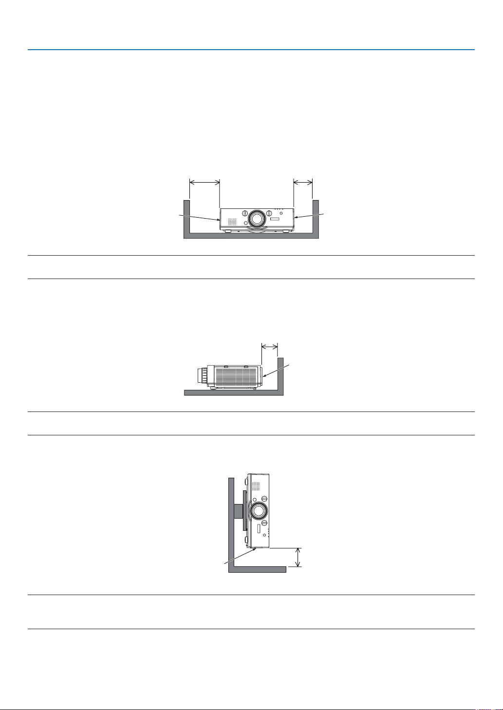
Clearance for Installing the Projector
Allowampleclearancebetweentheprojectoranditssurroundingsasshownbelow.
Thehightemperatureexhaustcomingoutofthedevicemaybesuckedintothedeviceagain.
AvoidinstallingtheprojectorinaplacewhereairmovementfromtheHVACisdirectedattheprojector.
HeatedairfromtheHVACcanbetakeninbytheprojector'sintakevent.Ifthishappens,thetemperatureinsidethe
projectorwillrisetoohighcausingtheover-temperatureprotectortoautomaticallyturnofftheprojectorspower.
Example 1 – If there are walls on both sides of the projector.
20cm/7.9"orgreater 13cm/5.1"orgreater
Filtercover
(Ventilation(inlet))
Lampcover
NOTE:
The drawing shows the proper clearance required for the front, back and top of the projector.
Example 2 – If there is a wall behind the projector.
10cm/3.9"orgreater
Ventilation(outlet)
NOTE:
The drawing shows the proper clearance required for the back, sides and top of the projector.
Example 3 – In the case of portrait projection.
Filtercover
(Ventilation(inlet))
13cm/5.1"orgreater
NOTE:
• Thedrawingshowstheproperclearancerequiredforthefront,backandtopoftheprojector.
• Seepage134 for an installation example on portrait projection.

viii
Table of Contents
Important Information ............................................................................................ i
1. Introduction ...........................................................................................................1
❶What’sintheBox? ..........................................................................................................1
❷IntroductiontotheProjector ...........................................................................................2
CongratulationsonYourPurchaseoftheProjector ..................................................2
Installation .................................................................................................................2
Videos .......................................................................................................................2
Network .....................................................................................................................3
Energy-saving ...........................................................................................................3
Maintenance .............................................................................................................3
Aboutthisuser’smanual ...........................................................................................4
❸PartNamesoftheProjector ...........................................................................................5
Front/Top ...................................................................................................................5
Rear ..........................................................................................................................6
ControlPanel/IndicatorSection ................................................................................7
TerminalPanelFeatures ...........................................................................................8
❹PartNamesoftheRemoteControl ................................................................................9
BatteryInstallation ..................................................................................................10
RemoteControlPrecautions ...................................................................................10
OperatingRangeforWirelessRemoteControl .......................................................11
2. Projecting an Image (Basic Operation) ...............................................12
❶FlowofProjectinganImage .........................................................................................12
❷ConnectingYourComputer/ConnectingthePowerCord ..............................................13
❸TurningontheProjector ...............................................................................................14
NoteonStartupscreen(MenuLanguageSelectscreen) .......................................15
❹SelectingaSource .......................................................................................................16
Selectingthecomputerorvideosource..................................................................16
❺AdjustingthePictureSizeandPosition ........................................................................18
Adjustingtheverticalpositionofaprojectedimage(Lensshift) .............................19
Focus ......................................................................................................................20
Applicablelens:NP30ZL .........................................................................................21
Applicablelens:NP11FL .........................................................................................22
Zoom .......................................................................................................................23
AdjustingtheTiltFeet .............................................................................................23
❻OptimizingComputerSignalAutomatically ..................................................................24
AdjustingtheImageUsingAutoAdjust ...................................................................24
❼TurningUporDownVolume .........................................................................................24
❽TurningofftheProjector ...............................................................................................25
❾AfterUse.......................................................................................................................26
3. Convenient Features ......................................................................................27
❶TurningofftheImageandSound .................................................................................27
❷FreezingaPicture ........................................................................................................28
❸EnlargingaPicture .......................................................................................................28
❹ChangingEcoMode/CheckingEnergy-SavingEffectUsingEcoMode[ECO
MODE] ....................................................................................................................29

ix
Table of Contents
CheckingEnergy-SavingEffect[CARBONMETER] ..............................................30
❺UsingtheOptionalRemoteMouseReceiver(NP01MR) .............................................31
❻CorrectingHorizontalandVerticalKeystoneDistortion[CORNERSTONE] .................33
❼PreventingtheUnauthorizedUseoftheProjector[SECURITY] ..................................36
❽Projecting3Dvideos.....................................................................................................39
Proceduretowatch3Dvideosusingthisprojector .................................................39
Whenvideoscannotbeviewedin3D .....................................................................41
❾ControllingtheProjectorbyUsinganHTTPBrowser ..................................................42
4. Multi-Screen Projection ...............................................................................48
❶Thingsthatcanbedoneusingmulti-screenprojection ................................................48
Case1.Usingasingleprojectortoprojecttwotypesofvideos[PIP/PICTURE
BYPICTURE] .........................................................................................................48
Case2.Usingfourprojectors(liquidcrystalpanel:XGA)toprojectvideoswith
aresolutionof1920×1080pixels[TILING]............................................................49
Thingstonotewheninstallingprojectors ................................................................51
❷DisplayingTwoPicturesattheSameTime ...................................................................52
Projectingtwoscreens ............................................................................................53
Switchingthemaindisplaywiththesub-displayandviceversa .............................54
Restrictions .............................................................................................................55
❸DisplayingaPictureUsing[EDGEBLENDING] ...........................................................56
Settingtheoverlapofprojectionscreens ................................................................57
BlackLevelAdjustment ...........................................................................................60
5. Using On-Screen Menu .................................................................................62
❶UsingtheMenus ...........................................................................................................62
❷MenuElements .............................................................................................................63
❸ListofMenuItems ........................................................................................................64
❹MenuDescriptions&Functions[INPUT] ......................................................................70
1:HDMI1 ..................................................................................................................70
2:HDMI2 ..................................................................................................................70
3:DisplayPort ...........................................................................................................70
4:BNC .....................................................................................................................70
5:BNC(CV) ..............................................................................................................70
6:BNC(Y/C) .............................................................................................................70
7:COMPUTER ........................................................................................................70
8:HDBaseT .............................................................................................................70
ENTRYLIST ...........................................................................................................70
TESTPATTERN ......................................................................................................70
❺MenuDescriptions&Functions[ADJUST] ...................................................................74
[PICTURE]
..............................................................................................................74
[IMAGEOPTIONS] .................................................................................................78
[VIDEO] ...................................................................................................................82
[3DSETTINGS] ......................................................................................................84
❻MenuDescriptions&Functions[DISPLAY] ..................................................................85
[PIP/PICTUREBYPICTURE] .................................................................................85
[GEOMETRICCORRECTION] ...............................................................................87
[EDGEBLENDING] ................................................................................................91
[MULTISCREEN]....................................................................................................92

x
Table of Contents
❼MenuDescriptions&Functions[SETUP] .....................................................................94
[MENU] ...................................................................................................................94
[INSTALLATION] .....................................................................................................96
[CONTROL] ............................................................................................................99
[NETWORKSETTINGS] .......................................................................................107
[SOURCEOPTIONS] ...........................................................................................112
[POWEROPTIONS] .............................................................................................114
ReturningtoFactoryDefault[RESET] ..................................................................116
❽MenuDescriptions&Functions[INFO.] .....................................................................118
[USAGETIME] ......................................................................................................118
[SOURCE(1)] ........................................................................................................119
[SOURCE(2)] ........................................................................................................119
[WIREDLAN] ........................................................................................................119
[VERSION(1)] .......................................................................................................120
[OTHERS] .............................................................................................................120
[CONDITIONS] .....................................................................................................121
[HDBaseT] ............................................................................................................122
6. Connecting to Other Equipment ...........................................................123
❶Mountingalens(soldseparately) ...............................................................................123
Mountingthelens..................................................................................................123
Removingthelens ................................................................................................124
❷MakingConnections ...................................................................................................125
AnalogRGBsignalconnection .............................................................................125
DigitalRGBsignalconnection ..............................................................................126
ConnectinganExternalMonitor ...........................................................................129
ConnectingYourBlu-rayPlayerorOtherAVEquipment .......................................130
ConnectingComponentInput ...............................................................................131
ConnectingHDMIInput.........................................................................................132
ConnectingtoaHDBaseTtransmissiondevice(soldcommercially) ....................133
Portraitprojection(verticalorientation) .................................................................134
ConnectingtoaWiredLAN ..................................................................................137
7. Maintenance .....................................................................................................138
❶CleaningtheFilters.....................................................................................................138
❷CleaningtheLens.......................................................................................................141
❸CleaningtheCabinet ..................................................................................................141
❹ReplacingtheLampandtheFilters ............................................................................142
8. User Supportware ..........................................................................................147
❶OperatingEnvironmentforSoftwareIncludedonCD-ROM .......................................147
NamesandFeaturesofBundledSoftwarePrograms ...........................................147
Downloadservice .................................................................................................147
OperatingEnvironment .........................................................................................147
❷InstallingSoftwareProgram .......................................................................................148
InstallationforWindowssoftware ..........................................................................148
❸OperatingtheProjectorViatheLAN(VirtualRemoteTool) ........................................151
ConnecttheprojectortoaLAN. ............................................................................152
❹ControllingtheProjectoroveraLAN(PCControlUtilityPro4/Pro5) ........................154

xi
Table of Contents
9. Appendix ..............................................................................................................158
❶Throwdistanceandscreensize .................................................................................158
Lenstypesandthrowdistance .............................................................................158
Tablesofscreensizesanddimensions ................................................................161
Lensshiftingrange ................................................................................................162
❷CompatibleInputSignalList .......................................................................................164
❸Specications .............................................................................................................167
❹CabinetDimensions ...................................................................................................169
❺Mountingthecablecover(soldseparately) ................................................................170
❻Pinassignmentsandsignalnamesofmainconnectors .............................................171
❼Troubleshooting ..........................................................................................................173
IndicatorMessages ...............................................................................................173
CommonProblems&Solutions ............................................................................175
Ifthereisnopicture,orthepictureisnotdisplayedcorrectly. ...............................177
❽PCControlCodesandCableConnection ..................................................................178
❾TroubleshootingCheckList .........................................................................................179
1
1. Introduction
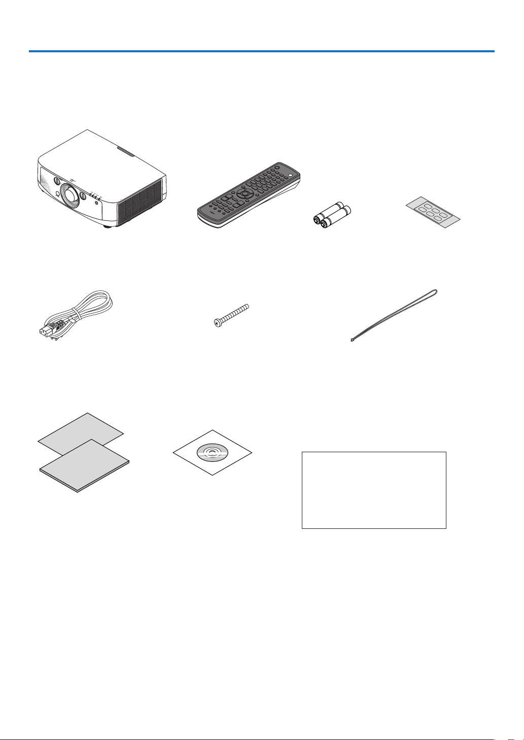
❶ What’s in the Box?
Makesureyourboxcontainseverythinglisted.Ifanypiecesaremissing,contactyourdealer.
Pleasesavetheoriginalboxandpackingmaterialsifyoueverneedtoshipyourprojector.
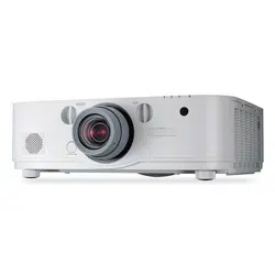
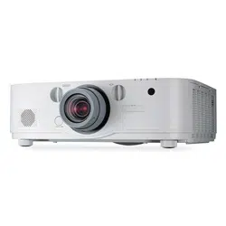
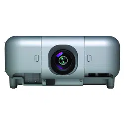
Projector
Dustcapforlens
* Theprojectorisshippedwithout
alens.Forthetypesoflensand
throwdistances,seepage158.
Remotecontrol
(7N900961)
AAalkalinebatteries
(x2)
Inputselectionchar-
acterseal
Powercord
(US:7N080241)
(EU:7N080022)
Lenstheftpreventionscrew
(24V00841)
Thisscrewmakesitdifcultto
removethelensmountedonthe
projector.(→page124)
Straps(24J23901)(forpreventinglampcoverfrom
falling)
Attachingthestrapstothelampcoverprevents
themfromfallingwhentheprojectorissuspended
fromtheceiling.
For North America only
Registrationcard
Limitedwarranty
For customers in Europe:
YouwillndourcurrentvalidGuar-
anteePolicyonourWebSite:
www.nec-display-solutions.com
• ImportantInfomation(ForNorth
America:7N8N4121)(ForOther
countriesthanNorthAmerica:
7N8N4121and7N8N4131)
• QuickSetupGuide(ForNorth
America:7N8N4141)(ForOther
countriesthanNorthAmerica:
7N8N4141and7N8N4151)
NECProjectorCD-ROM
User’smanual(PDF)andthe
utilitysoftware
(7N951971)

2
1. Introduction
❷ Introduction to the Projector
Thissectionintroducesyoutoyournewprojectoranddescribesthefeaturesandcontrols.
Congratulations on Your Purchase of the Projector
Thisprojectorisoneoftheverybestprojectorsavailabletoday.Theprojectorenablesyoutoprojectpreciseimages
upto500inchesacross(measureddiagonally)fromyourPCorMaccomputer(desktopornotebook),VCR,Blu-ray
player,ordocumentcamera.
Youcanusetheprojectoronatabletoporcart,youcanusetheprojectortoprojectimagesfrombehindthescreen,
andtheprojectorcanbepermanentlymountedonaceiling*
1
.Theremotecontrolcanbeusedwirelessly.
*
1
Donotattempttomounttheprojectoronaceilingyourself.
Theprojectormustbeinstalledbyqualiedtechniciansinordertoensureproperoperationandreducetherisk
ofbodilyinjury.
Inaddition,theceilingmustbestrongenoughtosupporttheprojectorandtheinstallationmustbeinaccordance
withanylocalbuildingcodes.Pleaseconsultyourdealerformoreinformation.
Installation
• Liquidcrystaltypehighbrightness/highresolutionprojector
Model Brightness Resolution AspectRatio
PA622U 6200lm WUXGA(1920×1200) 16:10
PA522U
5200lm WUXGA(1920×1200) 16:10
PA672W
6700lm WXGA(1280×800) 16:10
PA572W
5700lm WXGA(1280×800) 16:10
PA722X
7200lm XGA(1024×768) 4:3
PA622X
6200lm XGA(1024×768) 4:3
• Widerangeofoptionallensesselectableaccordingtotheplaceofinstallation
Thisprojectorsupports6typesofoptionallenses,providingaselectionoflensesadaptedtoavarietyofplaces
ofinstallationandprojectionmethods.
Inaddition,thelensescanbemountedandremovedinonetouch.
Notethatnolensismounteduponshipmentfromthefactory.Pleasepurchaseoptionallensesseparately.
• Lensshiftfunctionforeasilyadjustingthepositionoftheprojectedimage
Thepositionoftheprojectedimageismovedbyturningthetwodialsontheprojector’sfront,oneforthevertical
direction,oneforthehorizontaldirection.
• 360°installationangle(tilt-free)
Theprojectorcanbeinstalledatanyangle(360°).
Note,however,thatthe“fanmode”settingmustbechangedaccordingtotheangleofinstallation.
Also,theprojectorcannotbeinstalledtiltedtotheleftorright.
• Portraitprojectionispossible
Thisprojectorcanperformportraitprojectionwiththeprojectionscreenturned90°.
However,thelampreplacementtime*is2000hoursforportraitprojection.
* Replacementtimenotguaranteed.
Videos
• Widerangeofinput/outputconnectors(HDMI,DisplayPort,BNC,etc.)andbuilt-inmonauralspeaker
Theprojectorisequippedwithavarietyofinput/outputconnectors:HDMI(input×2,output×1),DisplayPort,BNC
(5-core),computer(analog),etc.
Theprojector’sHDMIinput/outputconnectorsandDisplayPortinputconnectorsupportHDCP.
Theprojectorisalsoequippedwithabuilt-in10Wmonauralspeaker.

3
1. Introduction
• EquippedwithHDBaseTinputterminal
ThisprojectorisequippedwithaHDBaseTinputterminalwhichcanbeconnectedtoaHDBaseTtransmission
devicesoldcommercially.
HDBaseTisaconnectionstandardforhomeappliancesthatisestablishedbytheHDBaseTAlliance.
• Simultaneousdisplayof2images(PIP/PICTUREBYPICTURE)
Twoimagescanbeprojectedsimultaneouslywithasingleprojector.
Therearetwotypesoflayoutsforthetwoimages:“picture-in-picture”inwhichasub-pictureisdisplayedonthe
mainpicture,and“picture-by-picture”inwhichthemainandsubpicturesaredisplayednexttoeachother.
• Multi-screenprojectionusingmultipleprojectors
ThisprojectorisequippedwithmultipleHDMIinput&outputterminalsthatcanconnectmultipleprojectorsina
digitalchain.Ahighqualitypictureisachievedbydividingandprojectinghighresolutionvideosamongthevarious
projectors.
Furthermore,theboundariesofthescreensaresmoothedusinganedgeblendingfunction.
• Seamlessswitchfunctionforsmootherscreenchangeswhenswitchingthesignal
Whentheinputconnectorisswitched,theimagedisplayedbeforeswitchingisheldsothatthatthenewimage
canbeswitchedtowithoutabreakduetoabsenceofasignal.
• SupportsHDMI3Dformat
Thisprojectorcanbeusedtowatchvideosin3Dusingcommercially-availableactiveshutter-type3Deyewear
and3DemittersthatsupportXpand3D.
Network
• Convenientutilitysoftware(UserSupportware)providedasstandard
ThethreeutilitysoftwarestoredintheenclosedNECProjectorCD-ROM(VirtualRemoteTool,PCControlUtility
Pro4(forWindows)andPCControlUtilityPro5(forMacOS))canbeused.Thefollowingthreeutilitysoftware
ontheCD-ROMcannotbeused.
ImageExpressUtilityLite(forWindows/MacOS),ImageExpressUtility2.0(forWindows)andDesktopControl
Utility1.0(forWindows)
Energy-saving
• Energy-saving design with a standby power consumption of 0.11 watts (100-130V)/0.16 watts (200-
240V)
Whentheon-screenmenu’sstandbymodeissetto“NORMAL”,thepowerconsumptioninthestandbymodeis
0.11watts.
• “Ecomode”forlowpowerconsumptionand“CarbonMeter”display
The projector is equipped with an “eco mode” for reducing powerconsumption during use. Furthermore, the
power-savingeffectwhentheecomodeissetisconvertedintotheamountofreductionsofCO
2
emissionsand
thisisindicatedontheconrmationmessagedisplayedwhenthepoweristurnedoffandat“Information”onthe
on-screenmenu(CARBONMETER).
Maintenance
• Maximumlampreplacementtimeof4000hoursandnoneedtocleanthelters
Whenusedintheecomode,thelampreplacementtime*isextendedtoamaximumof4000hours.
*Thistimeisnotguaranteed.
Furthermore,thisprojectoruseslarge2-layerlters.Whentheseltersarereplacedwithnewoneswhenchanging
thelamp,thereisnoneedforregularltercleaning.

4
1. Introduction
About this user’s manual
Thefastestwaytogetstartedistotakeyourtimeanddoeverythingrightthersttime.Takeafewminutesnowto
reviewtheuser’smanual.Thismaysaveyoutimelateron.Atthebeginningofeachsectionofthemanualyou’llnd
anoverview.Ifthesectiondoesn’tapply,youcanskipit.
5
1. Introduction
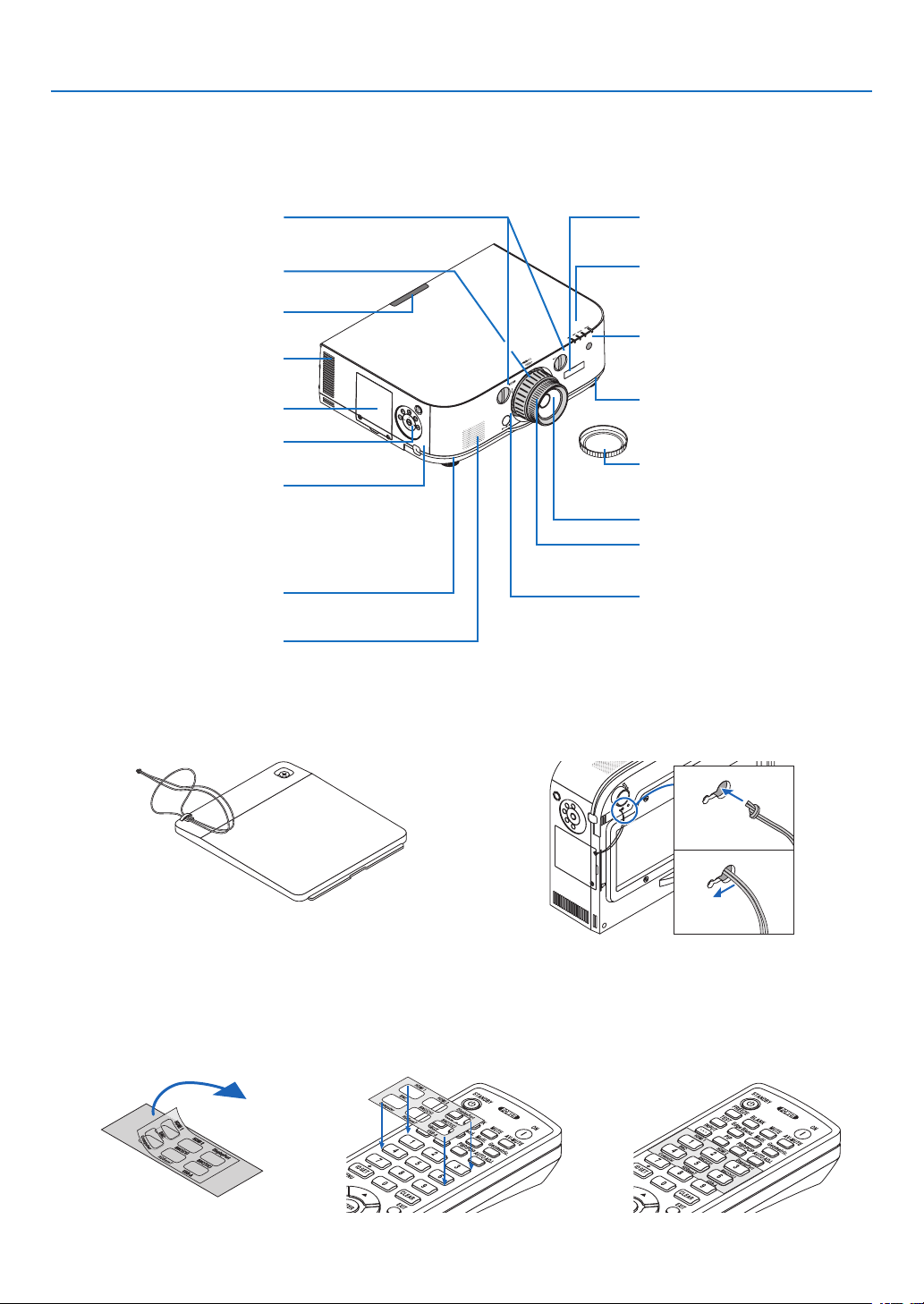
❸ Part Names of the Projector
Front/Top
Thelensissoldseparately.ThedescriptionbelowisforwhentheNP13ZLlensismounted.
ControlPanel
(→page7)
LensShiftDial(vertical/horizontal)
(→page19)
Lens
RemoteSensor(locatedonthe
frontandtherear)
(→page11)
RemoteSensor
(→page11)
ZoomLever/ZoomRing(→page
23)
LensCap
(Theoptionallensisshippedwith
thelenscap.)
FocusRing
(→page20)
AdjustableTiltFoot
(→page23)
IndicatorSection
(→page7)
Securinglevercover
(→page135)
LensReleaseButton
(→page124)
AdjustableTiltFoot
(→page23)
Ventilation(outlet)
Heatedairisexhaustedfromhere.
Mounting the strap
1. Mount the strap to the filter cover and lamp cover as shown on the diagram below.
2. Insert the knot in the strap into the hole on the bottom of the projector and pull in the direction of the arrow
to fasten.
a
b
Howtopastetheinputselectioncharacterstickeroftheremotecontrol
• PeeloffthecoverofthestickerandalignthestickerholeswithButtons1to6beforepasting.
• Pleasetakecarenottoletthestickercontactthebuttonswhenpasting.
• Theexplanationsandillustrationsinthismanualareprovidedwiththestickerpasted.
LampCover(→page143)
SecurityBar
Attachananti-theftdevice.
Thesecuritybaracceptssecurity
wiresorchainsupto0.18inch/4.6
mmindiameter.
MonauralSpeaker(10W)
6
1. Introduction
TerminalPanel
(→page8)
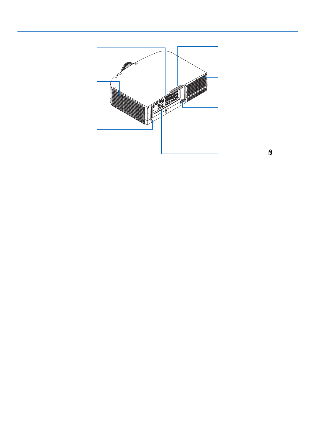
Rear
RemoteSensor(locatedonthe
frontandtherear)
(→page11)
ACInput
Connectthesuppliedpowercord’s
three-pinplughere,andplugthe
otherendintoanactivewalloutlet.
(→page13)
* ThissecurityslotsupportstheMicroSaver
®
SecuritySystem.
Built-inSecuritySlot( )*
Cablecoverconnection
(rightandleft)
Screwholesandgroovesforthe
optionalcablecover
(→page170)
Ventilation(inlet)/FilterCover
(→page138,145)
Ventilation(outlet)
Heatedairisexhaustedfromhere.
7
1. Introduction
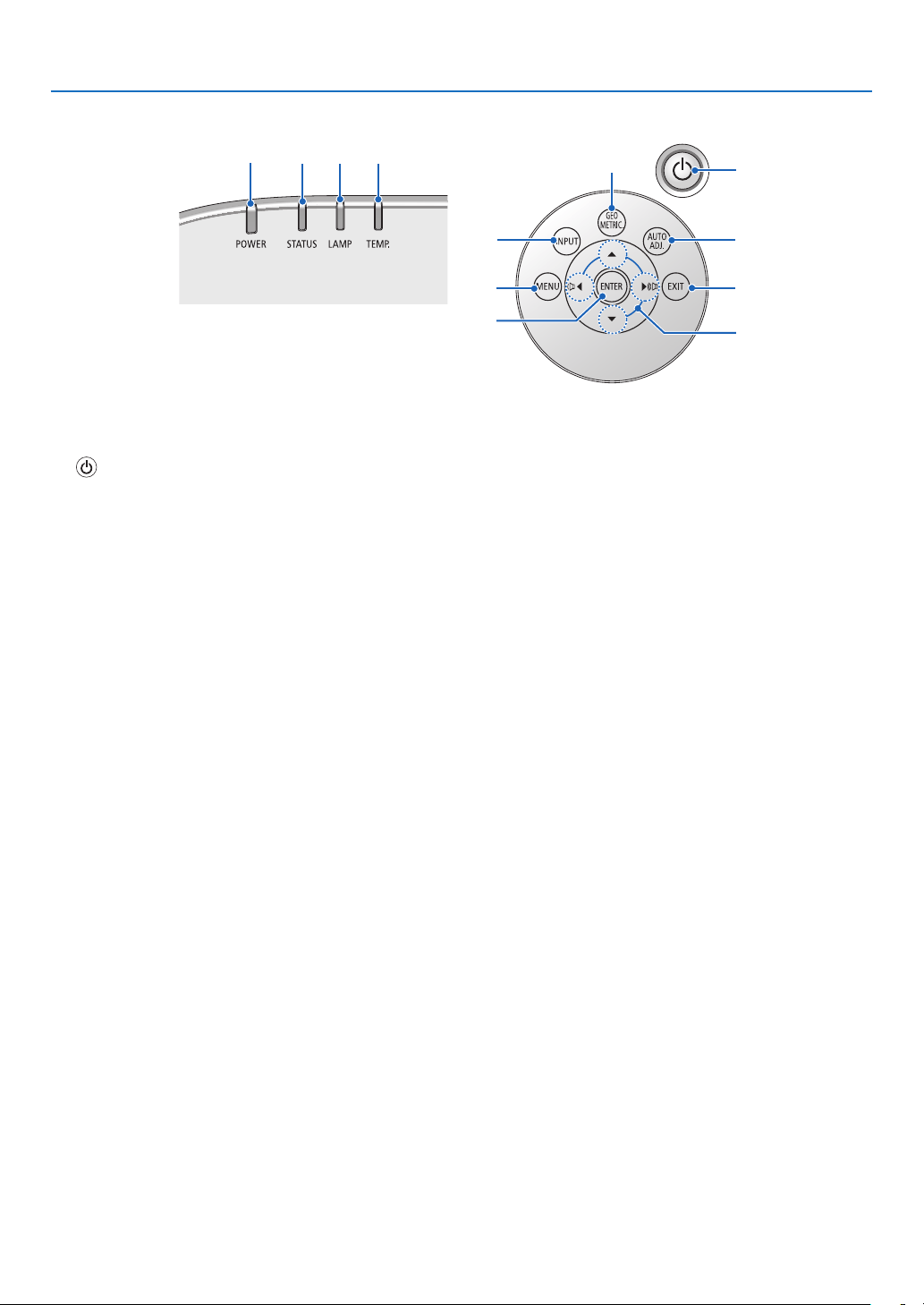
Control Panel/Indicator Section
11
10
7
2
3
4
5
8
1
6
12
9
1. (POWER)Button
(→page14,25)
2. POWER Indicator
(→page13,14,25,173)
3. STATUS Indicator
(→page173)
4. LAMP Indicator
(→page142,174)
5. TEMP. Indicator
(→page174)
6. INPUTButton
(→page16)
7. AUTO ADJ. Button
(→page24)
8. Geometric. Button
(→page33)
9. MENU Button
(→page62)
10.▲▼◀▶
/VolumeButtons◀▶
(→
page24,62)
11. ENTER Button
(→page62)
12. EXIT Button
(→page62)
8
1. Introduction
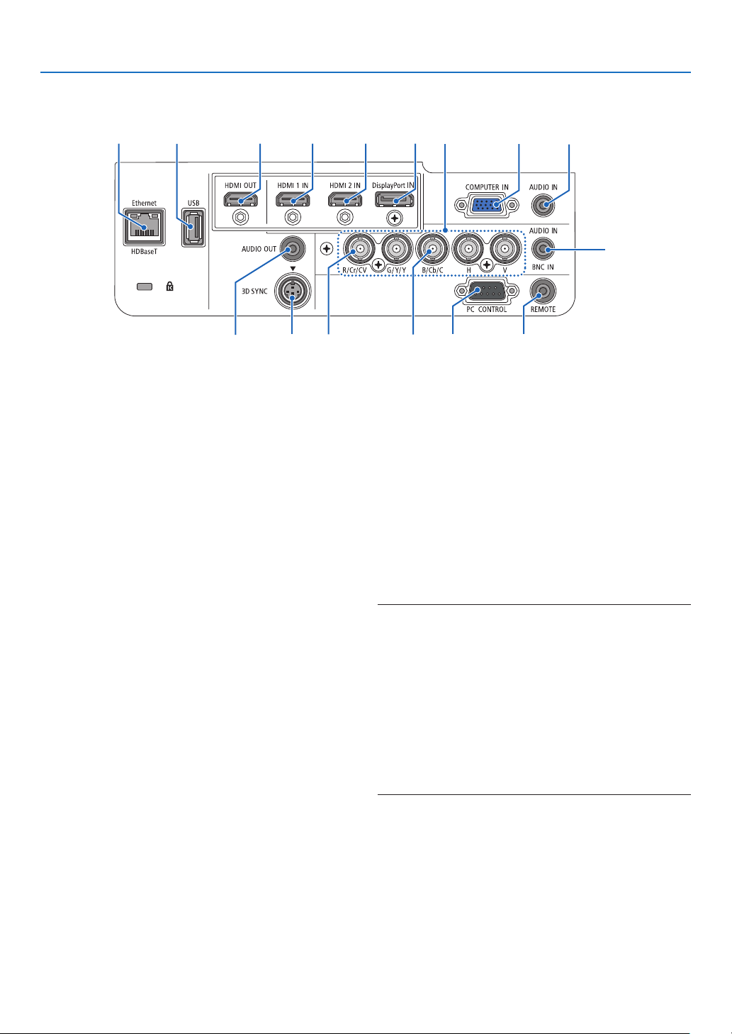
Terminal Panel Features
2 3112
8
9
10
11
7
4
5
15 16
13
14
6
1. HDMI1INConnector(TypeA)
(→page126,128,132,171)
2. HDMI2INConnector(TypeA)
(→page126,128,132,171)
3. DisplayPortINConnector
(→page126,171)
4. BNCIN[R/Cr/CV,G/Y/Y,B/Cb/C,H,V]Connec-
tors(BNC×5)
(→page125,130)
5. BNC(CV)InputConnector(BNC×1)
(→page130)
6. BNC(Y/C)InputConnector(BNC×2)
(→page130)
7. BNCAUDIOINMiniJack(StereoMini)
(→page128,130)
8. COMPUTERIN/ComponentInputConnector
(MiniD-Sub15Pin)
(→page13,125)
9. COMPUTERAUDIOINMiniJack(StereoMini)
(→page13,125)
10.Ethernet/HDBaseTPort(RJ-45)
(→page133,172)
11.USB-APort(TypeA)
(→page172)
(Forfutureexpansion.Thisportallowsforpowersup-
ply.)
12.HDMIOUTConnector(TypeA)
(→page129)
13.AUDIOOUTMiniJack(StereoMini)
(→page129)
14.3DSYNCConnector(MiniDIN4Pin)
(→page39)
15.PCCONTROLPort(D-Sub9Pin)
(→page172)
Use this port to connect a PC or control system.
Thisenablesyoutocontroltheprojectorusingserial
communicationprotocol.Ifyouarewritingyourown
program,typicalPCcontrolcodesareonpage178.
16.REMOTEConnector(StereoMini)
Use this connector forwired remote control of the
projectorusingtheNECoptionalremotecontrol.
Connect the projector and optional remote control
usingacommerciallyavailablewiredremotecontrol
cable.
NOTE:
• WhenaremotecontrolcableisconnectedtotheREMOTE
connector, infrared remote control operations cannot be
performed.
• When [HDBaseT] is selected in the [REMOTE SENSOR]
and the projector is connected to a commercially-available
transmissiondevicethatsupportsHDBaseT,remotecontrol
operations in infra-red cannot be carried out if transmission
of remote control signals has been set up in the transmission
device.However,remotecontrolusinginfraredrayscanbe
carried out when the power supply of the transmission device
is switched off.
9
1. Introduction
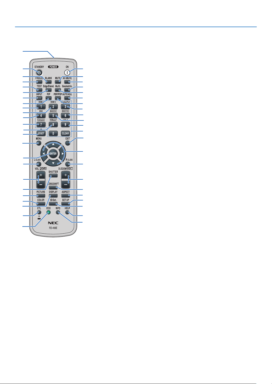
❹ Part Names of the Remote Control
8. TEST Button
(→page70)
9. Edge Blend. Button
(→page91)
10.Multi.Button
(→page92)
11. Geometric. Button
(→page33)
12. INPUT Button
(→page16)
13. PIP Button
(→page53)
14.PBP/POPButton
(→page53)
15. AUTO ADJ. Button
(→page24)
16.1(HDMI1)Button
(→page16)
17.2(HDMI2)Button
(→page16)
18.3(DisplayPort)Button
(→page16)
19.4(BNC)Button
(→page16)
20.5(BNC(CV))Button
(→page16)
21.6(BNC(Y/C))Button
(→page16)
22.7(Computer)Button
(→page16)
23.8(HDBaseT)Button
(→page16)
24.9(USB-A)Button
(→page16)
25. ID SET Button
(→page105)
26.NumericKeypadButton/
CLEAR Button
(→
page105)
27. MENU Button
(→page62)
28. EXIT Button
(→page62)
1. Infrared Transmitter
(→page11)
2. POWER ON Button
(→page14)
3. STANDBY Button
(→page25)
4. FREEZE Button
(→page28)
5. BLANKButton
(→page27)
6. MUTEButton
(→page27)
7. AV-MUTEButton
(→page27)
29. ▲▼◀▶ Button
(→
page62)
30.ENTERButton
(→page62)
31.L-CLICKButton*
(→page32)
32.R-CLICKButton*
(→page32)
33.VOL./FOCUS(+)(−)Button
(→page24)
34.D-ZOOM/ZOOM(+)(−)Button
(→page28)
(“ZOOM”Buttondoesnotworkon
thisseriesofprojectors)
35. SHUTTER Button
(not available on this series of
projectors)
36.LENSSHIFTButton
(not available on this series of
projectors)
37. PICTURE Button
(→page74,76)
38. DISPLAY Button
(→page85)
39. ASPECT Button
(→page80)
40.COLORButton
(→page76)
41. 3D Set. Button
(→page39)
42. SETUP Button
(→page94)
43. CTL Button
(→page31,32)
44. ECO Button
(→page29)
45. INFO Button
(→page118)
46.HELPButton
(→page118)
1
3
5
4
8
9
12
13
2
6
7
11
10
15
14
16
19
22
25
23
17
27
31
33
35
30
21
28
29
20
32
24
26
18
34
36
43
44
46
45
37
40
38
42
41
39
* The▲▼◀▶,L-CLICKandR-CLICKbuttonsworkonlywhenaUSBcableisconnectedwithyourcomputer.
10
1. Introduction
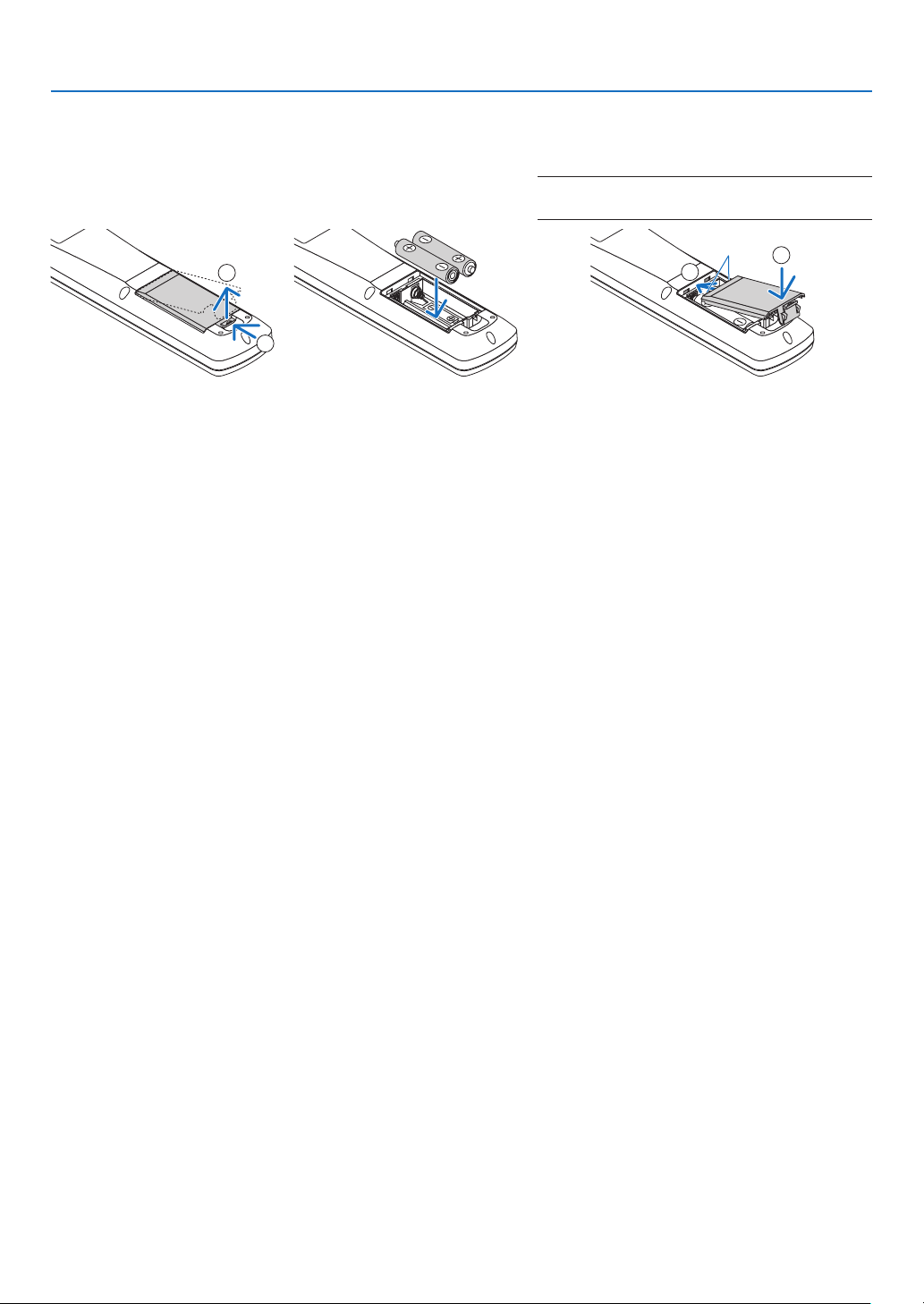
Battery Installation
1. Press the catch and remove
the battery cover.
2. Install new ones (AA). En-
sure that you have the bat-
teries’ polarity (+/−) aligned
correctly.
3. Slip the cover back over the batteries until
it snaps into place.
NOTE:Donotmixdifferenttypesofbatteriesornew
and old batteries.
1
2
1
2
Remote Control Precautions
• Handletheremotecontrolcarefully.
• Iftheremotecontrolgetswet,wipeitdryimmediately.
• Avoidexcessiveheatandhumidity.
• Donotshort,heat,ortakeapartbatteries.
• Donotthrowbatteriesintore.
• Ifyouwillnotbeusingtheremotecontrolforalongtime,removethebatteries.
• Ensurethatyouhavethebatteries’polarity(+/−)alignedcorrectly.
• Donotusenewandoldbatteriestogether,orusedifferenttypesofbatteriestogether.
• Disposeofusedbatteriesaccordingtoyourlocalregulations.
11
1. Introduction
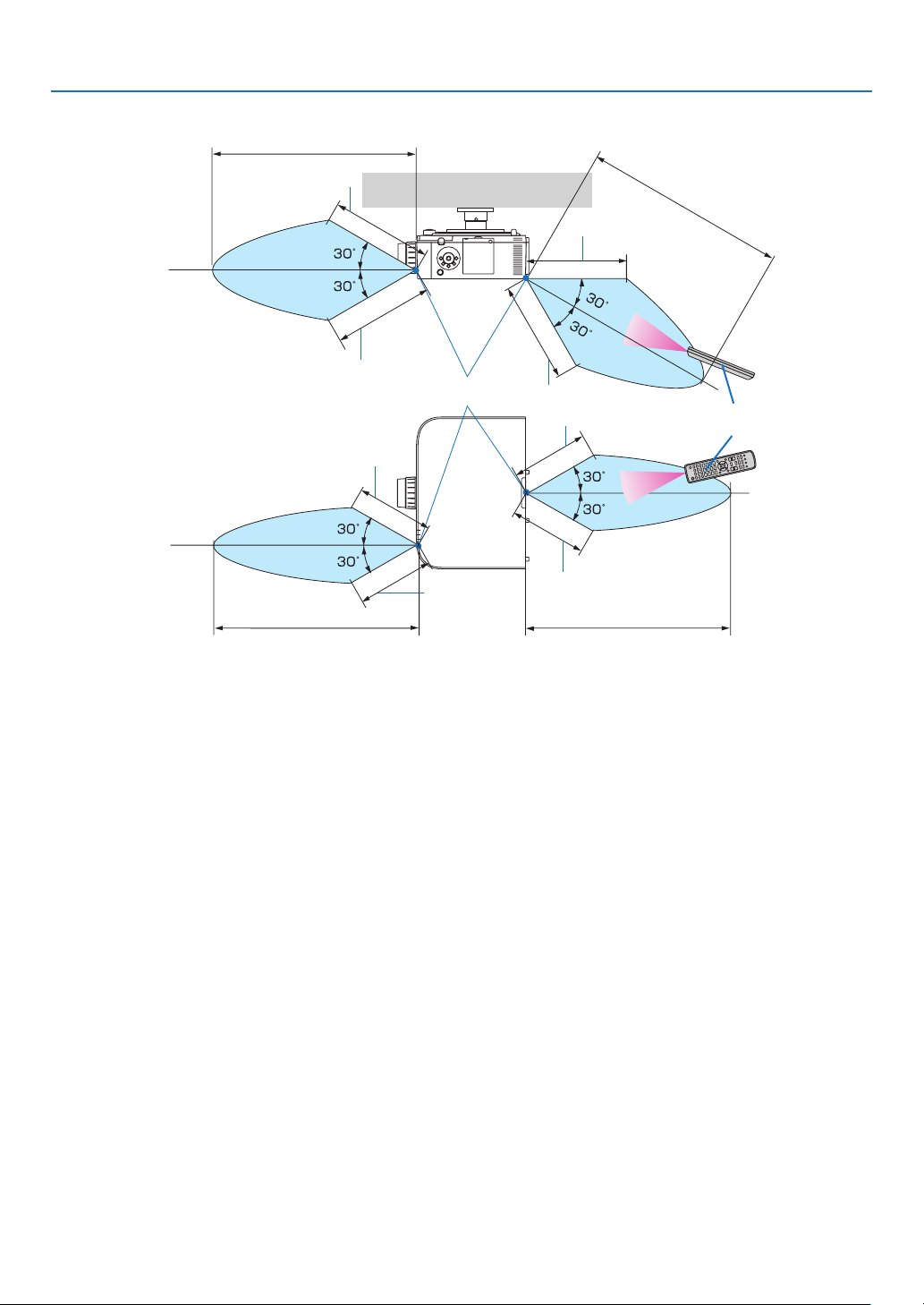
Operating Range for Wireless Remote Control
40m/1575inch
40m/1575inch
Remotecontrol
Remotesensoronprojectorcabinet
40m/1575inch
40m/1575inch
20m/787inch
20m/787inch
20m/787inch
20m/787inch
15m/591inch
15m/591inch
15m/591inch
15m/591inch
• Theinfraredsignaloperatesbyline-of-sightuptoadistanceofabovemetersandwithina60-degreeangleofthe
remotesensorontheprojectorcabinet.
• Theprojectorwillnotrespondifthereareobjectsbetweentheremotecontrolandthesensor,orifstronglightfalls
onthesensor.Weakbatterieswillalsopreventtheremotecontrolfromproperlyoperatingtheprojector.

12
Thissectiondescribeshowtoturnontheprojectorandtoprojectapictureontothescreen.
❶ Flow of Projecting an Image
Step 1
• Connectingyourcomputer/Connectingthepowercord(→ page 13)
Step 2
• Turningontheprojector(→ page 14)
Step 3
• Selectingasource(→ page 16)
Step 4
• Adjustingthepicturesizeandposition(→ page 18)
• Correctingkeystonedistortion[KEYSTONE](→ page 33)
Step 5
• Adjustingapictureandsound
- Optimizingacomputersignalautomatically(→page24)
- Turningupordownvolume(→page24)
Step 6
• Makingapresentation
Step 7
• Turningofftheprojector(→ page 25)
Step 8
• Afteruse(→ page 26)
2. Projecting an Image (Basic Operation)
13
2. Projecting an Image (Basic Operation)
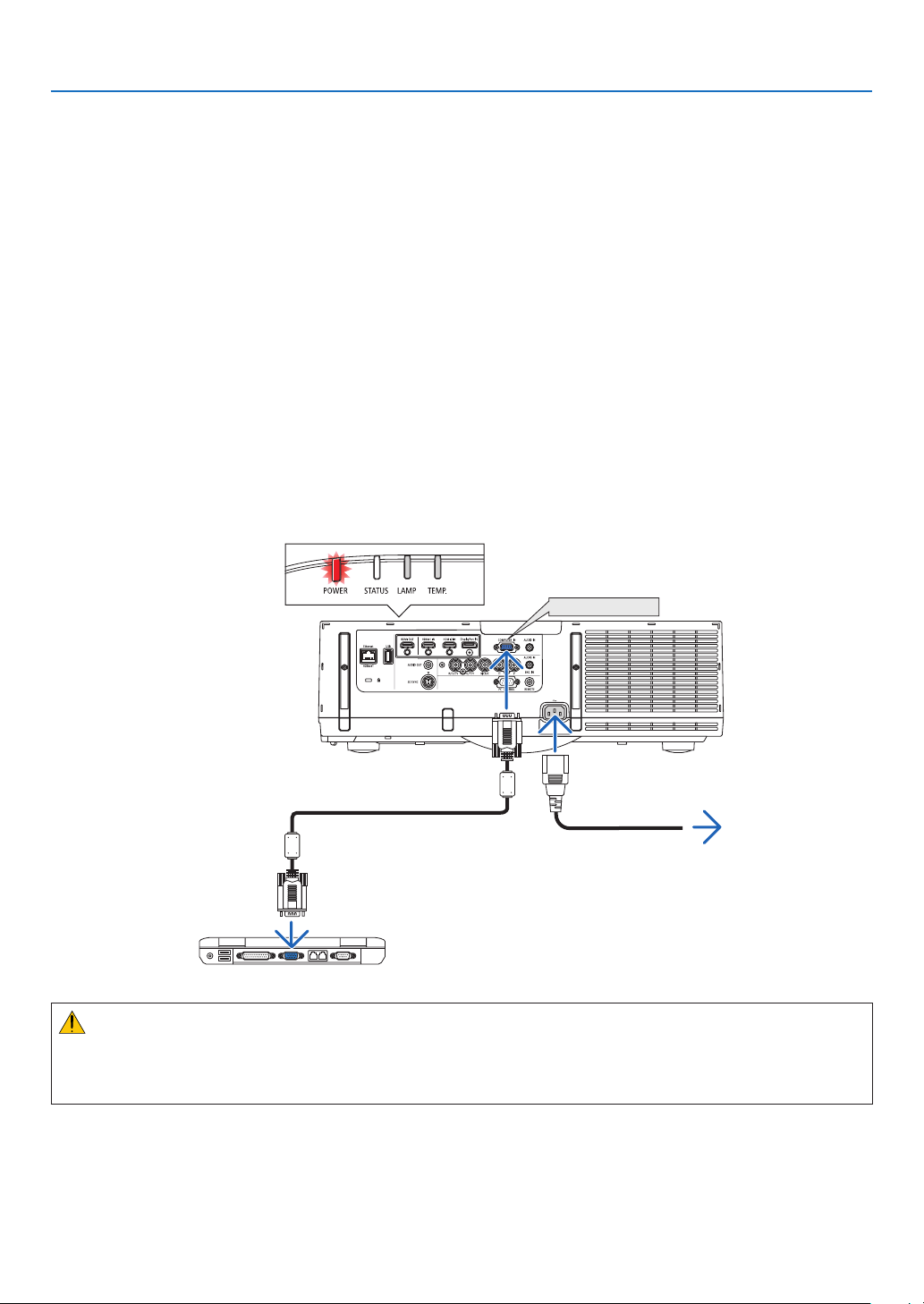
❷ Connecting Your Computer/Connecting the Power Cord
1. Connectyourcomputertotheprojector.
Thissectionwillshowyouabasicconnectiontoacomputer.Forinformationaboutotherconnections,see“(2)
MakingConnections”onpage125.
Connectthedisplayoutputterminal(miniD-sub15pin)onthecomputertothecomputervideoinputterminalon
theprojectorwithacommercially-availablecomputercable(withferritecore)andthenturntheknobsofthecon-
nectorstosecurethem.
2. Connectthesuppliedpowercordtotheprojector.
Firstconnectthesuppliedpowercord’sthree-pinplugtotheACINoftheprojector,andthenconnecttheother
plugofthesuppliedpowercordinthewalloutlet.
Uponconnectingthepowercable,thePOWERindicatoroftheprojectorwilllightupinorange.Iftherearenoinput
signals,thedevicewillgointothestandbymodeafterabout10secondsandlightupinred*.
TheSTATUSindicatorwilllightoff*.
*Thiswillapplyforbothindicatorswhen[NORMAL]isselectedfor[STANDBYMODE].SeethePowerIndicator
section.(→page173)
COMPUTER IN
Makesurethattheprongsarefullyinsertedinto
boththeACINandthewalloutlet.
Towalloutlet
Computercable(withferritecore)
(soldcommercially)
CAUTION:
PartsoftheprojectormaybecometemporarilyheatediftheprojectoristurnedoffwiththePOWERbuttonorifthe
ACpowersupplyisdisconnectedduringnormalprojectoroperation.
Usecautionwhenpickinguptheprojector.
14
2. Projecting an Image (Basic Operation)
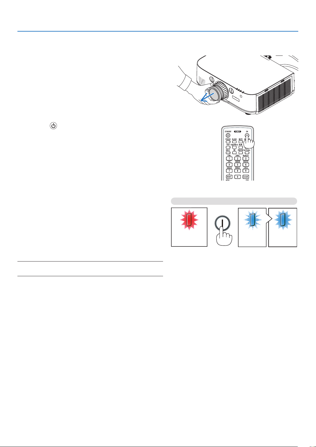
Standby Blinking Power On
Steady red light Blinking blue
light
Steady blue
light
❸ Turning on the Projector
1. Remove the lens cap.
2. Press the (POWER) button on the projector cabinet
or the POWER ON button on the remote control.
ThePOWERindicator willlightupin bluefrom red and
thenstartblinking.Afterthat,theimagewillbeprojected
ontothescreen.
TIP:
• Whenthemessage“PROJECTORISLOCKED!ENTERYOUR
PASSWORD.” is displayed, it means that the [SECURITY]
feature is turned on. (→ page 36)
• When the ECO message is displayed, it means that [ON] is
selectedfor[ECOMESSAGE].(→ page 95)
• PressingbuttonssuchaspowerbuttonandMENUbuttonwill
makesound.Toturnoffthebeepsound,select[OFF]for[BEEP]
from the menu. (→ page 106)
Afteryouturnonyourprojector,ensurethatthecomputer
orvideosourceisturnedon.
NOTE: A blue screen (blue background) is displayed when no signal
is being input (by factory default menu settings).
(→page173)
15
2. Projecting an Image (Basic Operation)
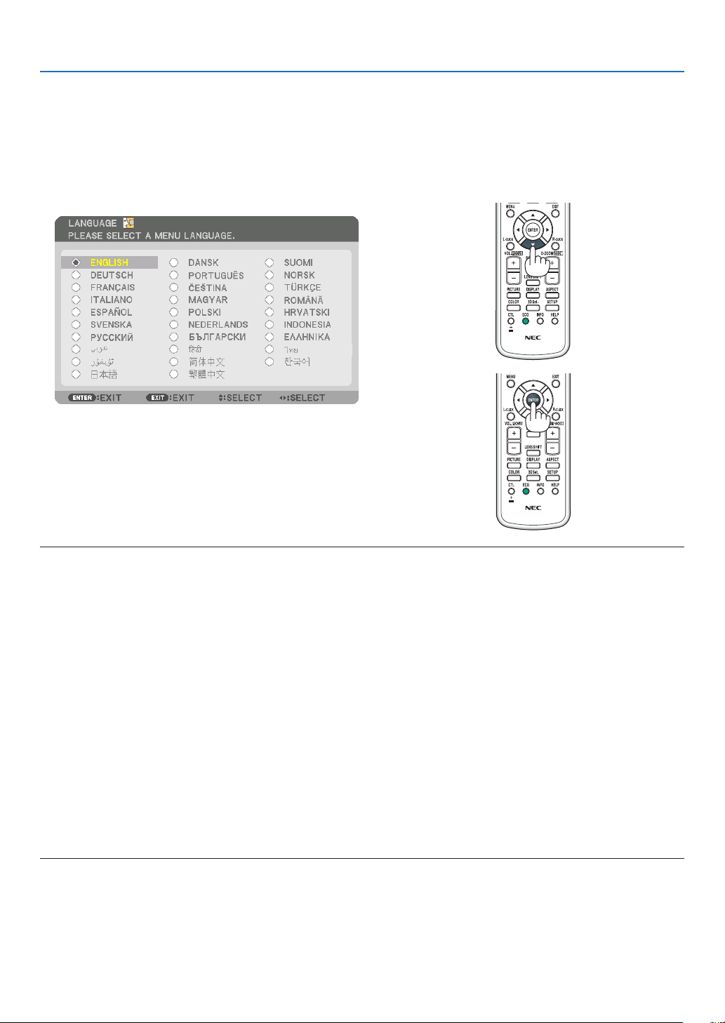
Note on Startup screen (Menu Language Select screen)
Whenyourstturnontheprojector,youwillgettheStartupmenu.Thismenugivesyoutheopportunitytoselectone
ofthe29menulanguages.
Toselectamenulanguage,followthesesteps:
1. Use the ▲, ▼, ◀ or ▶ button to select one of the 29
languages from the menu.
2. Press the ENTER button to execute the selection.
After this has been done, you can proceed to the menu
operation.
Ifyouwant,youcanselectthemenulanguagelater.
(→[LANGUAGE]onpage66and94)
NOTE:
• Duringprojection,aftershuttingdownthepowersupply(directpoweroff),waitforabout1minuteorlongerbeforeturningon
the power again.
• Keepthelenscapoffthelenswhiletheprojector’spowerison.
If the lens cap is on, it could be warped due to high temperature.
• Ifoneofthefollowingthingshappens,theprojectorwillnotturnon.
- If the internal temperature of the projector is too high, the projector detects abnormal high temperature. In this condition the
projectorwillnotturnontoprotecttheinternalsystem.Ifthishappens,waitfortheprojector’sinternalcomponentstocool
down.
- Whenthelampreachesitsendofusablelife,theprojectorwillnotturnon.Ifthishappens,replacethelamp.
- IftheSTATUSindicatorlightsorangewiththepowerbuttonpressed,itmeansthatthe[CONTROLPANELLOCK]isturnedon.
Cancelthelockbyturningitoff.(→ page 104)
- Ifthelampfailstolight,andiftheLAMPindicatorashesonandoffinacycleofsixtimes,waitafullminuteandthenturnon
the power.
• WhilethePOWERindicatorisblinkingblueinshortcycles,thepowercannotbeturnedoffbyusingthepowerbutton.
• Immediatelyafterturningontheprojector,screenickermayoccur.Thisisnormal.Wait3to5minutesuntilthelamplightingis
stabilized.
• Whentheprojectoristurnedon,itmaytakesometimebeforethelamplightbecomesbright.
• Ifyouturnontheprojectorimmediatelyafterthelampisturnedofforwhenthetemperatureishigh,thefansrunwithoutdisplay-
ing an image for some time and then the projector will display the image.
16
2. Projecting an Image (Basic Operation)
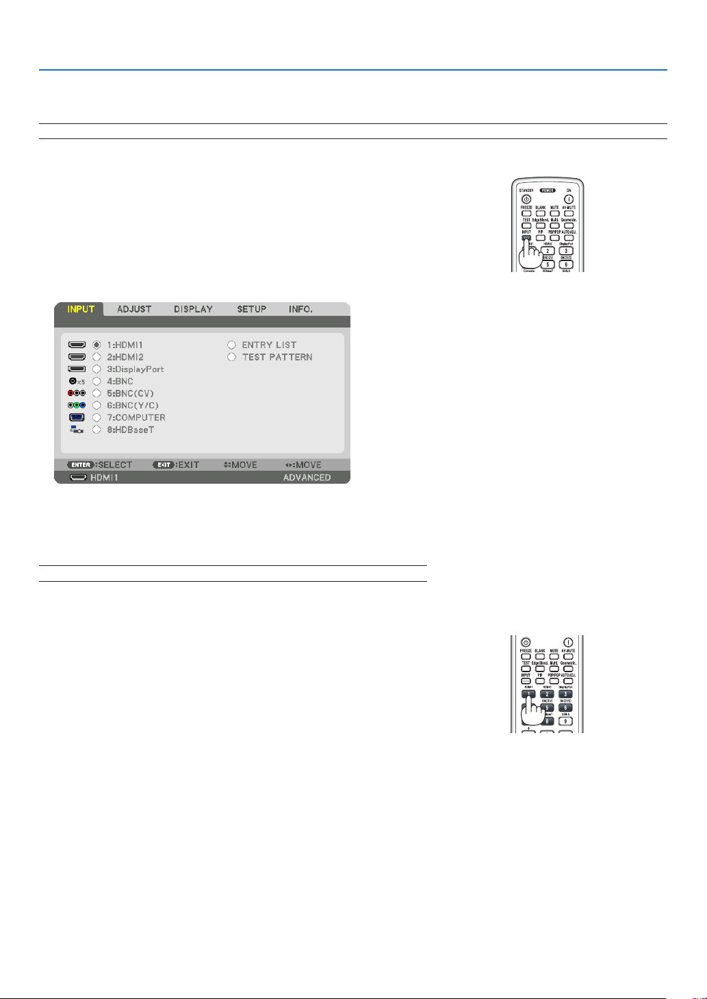
❹ Selecting a Source
Selecting the computer or video source
NOTE: Turn on the computer or video source equipment connected to the projector.
DetectingtheSignalAutomatically
PresstheINPUTbuttonfor1secondorlonger.Theprojectorwillsearch
fortheavailableinputsourceanddisplayit.Theinputsourcewillchange
asfollows:
HDMI1→HDMI2→DisplayPort→BNC→BNC(CV)→BNC(Y/C)→
COMUPTER→HDBaseT→HDMI1→ …
• Pressitbrieytodisplaythe[INPUT]screen.
Pressthe▼/▲buttonstomatchthetargetinputterminalandthen
presstheENTERbuttontoswitchtheinput.Todeletethemenudisplay
inthe[INPUT]screen,presstheMENUorEXITbutton.
TIP: If no input signal is present, the input will be skipped.
Using the Remote Control
Press any one of the 1/HDMI 1, 2/HDMI 2, 3/DisplayPort, 4/BNC, 5/
BNC(CV),6/BNC(Y/C),7/Computer,or8/HDBaseTbuttons.
17
2. Projecting an Image (Basic Operation)
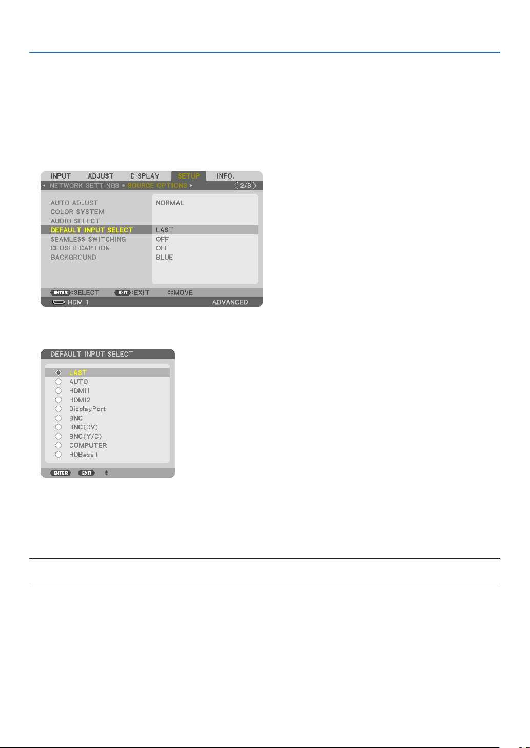
Selecting Default Source
Youcansetasourceasthedefaultsourcesothatitwillbedisplayedeachtimetheprojectoristurnedon.
1. Press the MENU button.
Themenuwillbedisplayed.
2. Press the ▶buttontoselect[SETUP]andpressthe▼buttonortheENTERbuttontoselect[BASIC].
3. Press the ▶buttontoselect[SOURCEOPTIONS].
4. Press the ▼buttonfourtimestoselect[DEFAULTINPUTSELECT]andpresstheENTERbutton.
The[DEFAULTINPUTSELECT]screenwillbedisplayed.
(→page112)
5. Select a source as the default source, and press the ENTER button.
6. Press the EXIT button a few times to close the menu.
7. Restart the projector.
Thesourceyouselectedinstep5willbeprojected.
NOTE:Evenwhen[AUTO]isturnedon,the[HDBaseT]willnotbeautomaticallyselected.Tosetyournetworkasthedefaultsource,
select[HDBaseT].
TIP:
• WhentheprojectorisinStandbymode,applyingacomputersignalfromacomputerconnectedtotheCOMPUTERINinputwill
powerontheprojectorandsimultaneouslyprojectthecomputer’simage.
([AUTOPOWERONSELECT]→ page 115)
• OntheWindows7keyboard,acombinationoftheWindowsandPkeysallowsyoutosetupexternaldisplayeasilyandquickly.
18
2. Projecting an Image (Basic Operation)
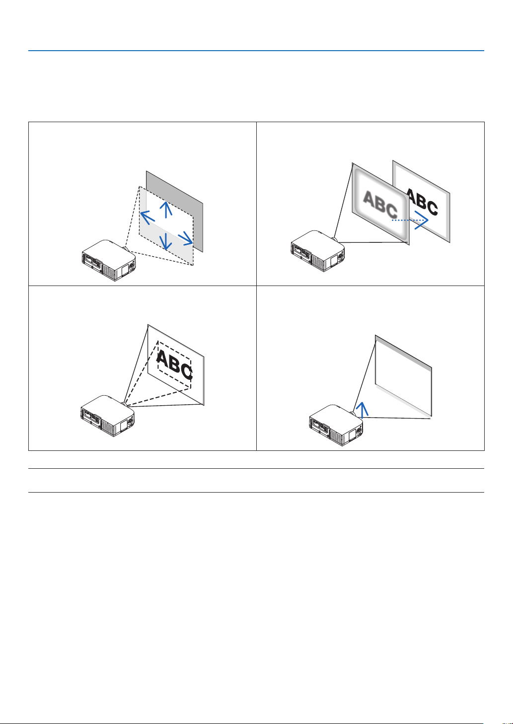
❺ Adjusting the Picture Size and Position
Usethelensshiftdial,theadjustabletiltfootlever,thezoomlever/zoomringandthefocusringtoadjustthepicture
sizeandposition.
Inthischapterdrawingsandcablesareomittedforclarity.
Adjustingtheprojected image’s vertical and horizontal
position
[Lensshift]
(→page19)
Adjustingthefocus
[Focusring]
(→page20)
Finelyadjustingthesizeofanimage
[Zoomlever/Zoomring]
(→page21,23)
Adjusting the projected image’s height and horizontal
tilt
[Tiltfoot]*¹
(→page23)
NOTE*
1
:Adjusttheprojectedimage’sheightusingthetiltfeetwhenyouwanttoprojecttheimageatapositionhigherthanthelens
shift adjustment range.
19
2. Projecting an Image (Basic Operation)
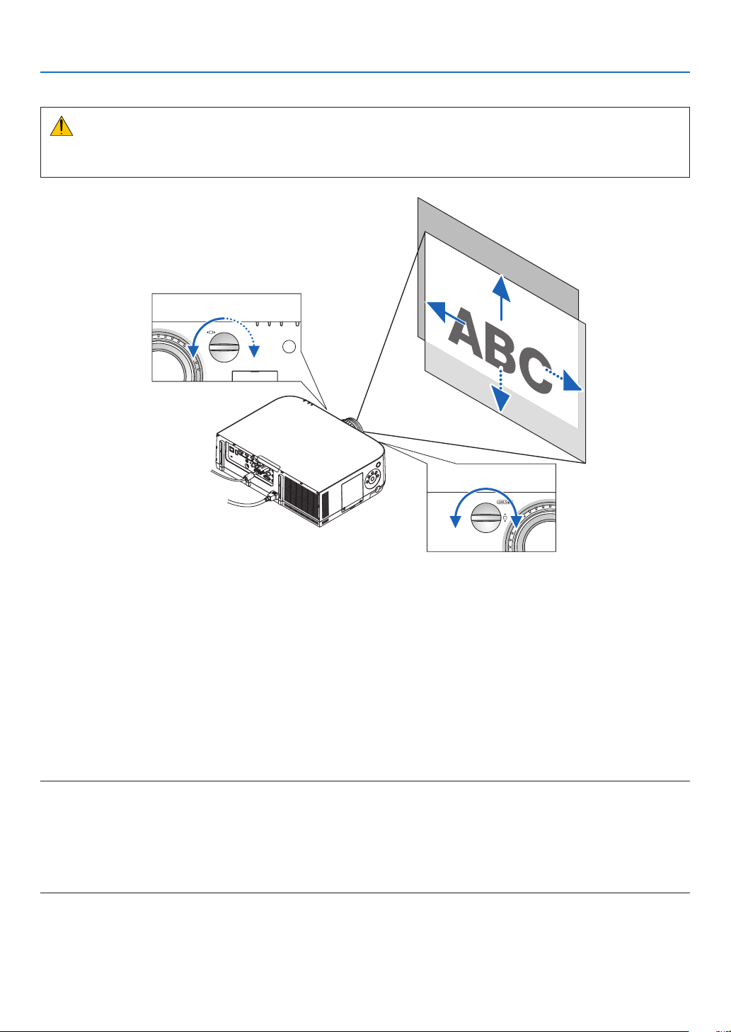
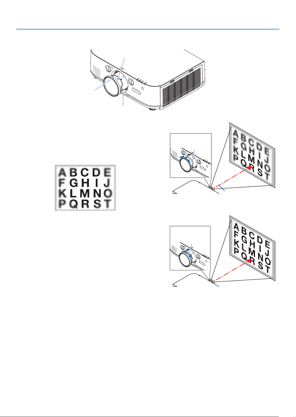
Adjusting the vertical position of a projected image (Lens shift)
CAUTION
Performtheadjustmentfrombehindorfromthesideoftheprojector.Adjustingfromthefrontcouldexposeyour
eyestostronglightwhichcouldinjurethem.
Downward
Upward
Lensshiftdial(Horizontal)
Lensshiftdial(Vertical)
RightwardLeftward
• Turnthelensshiftdialsclockwiseorcounterclockwise.
Verticaldial
Turnthisclockwiseorcounterclockwisetoadjusttheprojectionpositionintheverticaldirection.
Approximateturningrange:About6turnscounterclockwise,about2turnsclockwisewhenthelensisatthecenter
position.
Horizontaldial
Turnthisclockwiseorcounterclockwisetoadjusttheprojectionpositioninthehorizontaldirection.
Approximateturningrange:About1turn counterclockwise,about1turnclockwisewhenthelensisat thecenter
position.
NOTE:
• Thedialscanbeturnedmorethanonefullturn,buttheprojectionpositioncannotbemovedmorethantherangeindicatedon
the following page.
• Ifthelensisshiftedtothemaximuminthediagonaldirection,theedgesofthescreenwillbedarkorshaded.
• Theverticalshiftadjustmentmustbenishedwithanimageshiftedupward.Ifyounishtheverticalshiftadjustmentwithan
image shifted down, the zoom/focus adjustments or strong shaking may cause a projected image to slightly shift down.
• ThelensshiftfunctioncannotbeusedwhenusingtheseparatelysoldNP11FLlens.
20
2. Projecting an Image (Basic Operation)
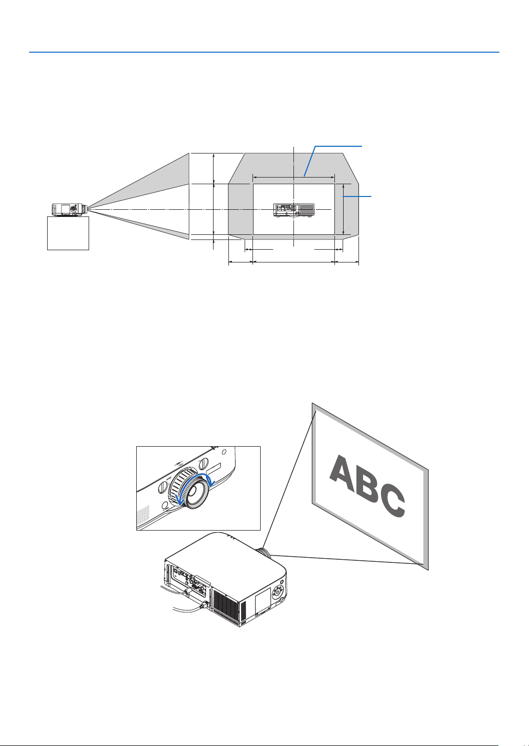
TIP:
• ThediagrambelowshowsthelensshiftadjustmentrangeforthePA622UandPA522U(projectionmode:desktopfront).Toraise
the projection position higher than this, use the tilt feet. (→ page 23)
• ForthePA672W/PA572W/PA722X/PA622Xandtheceilingmount/frontprojectionlensshiftadjustmentrange,seepage162,
163.
100%V
50%V
10%V
100%H
30%H 30%H
10%H 10%H
Heightofprojectedimage
Widthofprojectedimage
PA622U/PA522U
Descriptionofsymbols:Vindicatesvertical(heightoftheprojectedimage),Hindicateshorizontal(widthoftheprojectedim-
age).
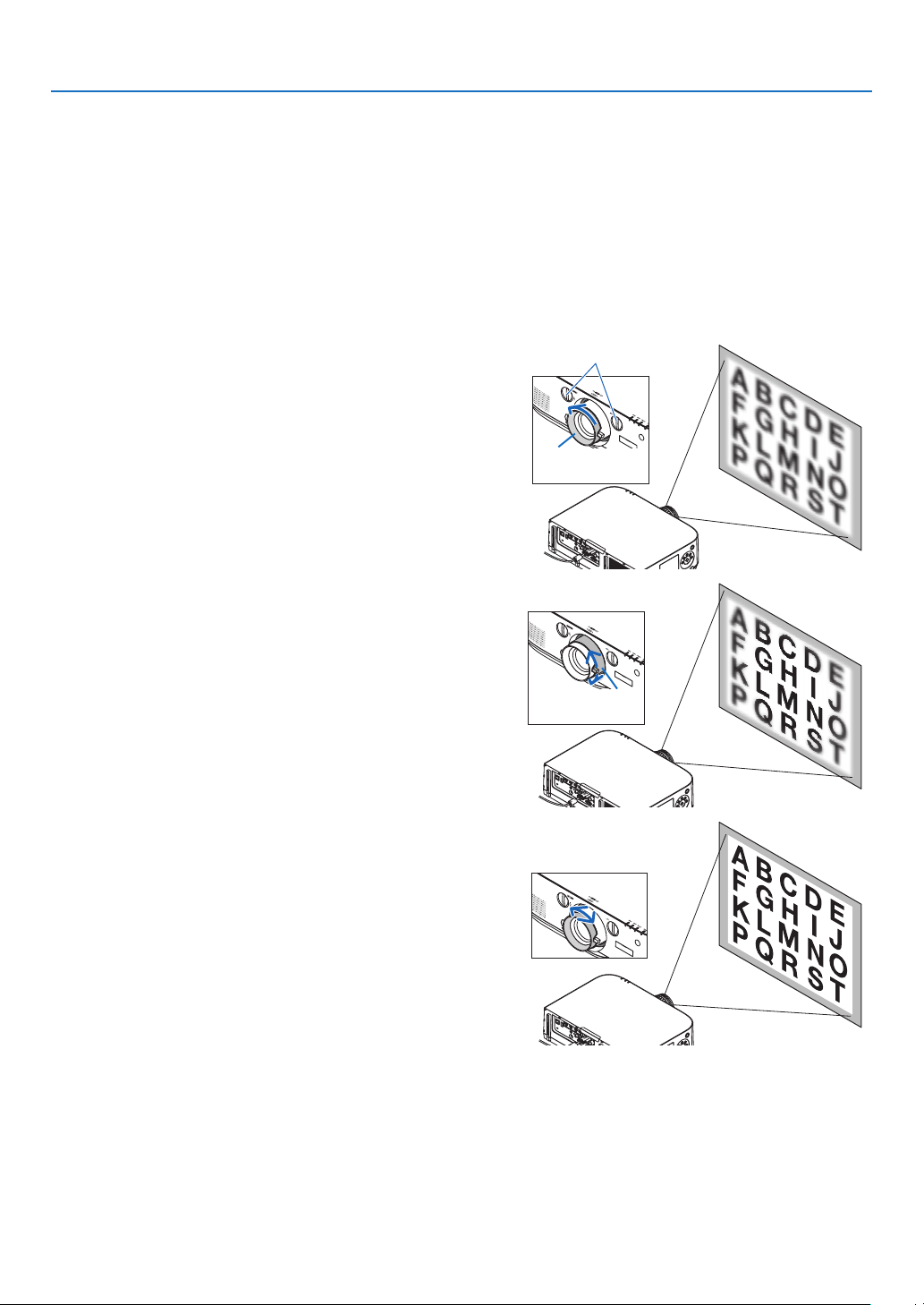
Focus
Applicablelens:NP12ZL/NP13ZL/NP14ZL/NP15ZL
UsetheFOCUSringtoobtainthebestfocus.
Focusring
21
2. Projecting an Image (Basic Operation)
Applicable lens: NP30ZL
TheNP30ZLlensunitalignstheperipheralfocusaroundtheopticalaxis.
Peripheralfocusring
FocusRing
ZoomLever
1. Turn the focus ring left and right to align the focus
around the optical axis.
* Thediagramshowsanexamplewhenthelensshiftis
movedtothetop.Thetopofthescreenisadjusted.
Whenthelensisinthecenter,thecenterofthescreen
isadjusted.
FocusRing
Opticalaxis
2. Turn the peripheral focus ring to the left and right to
align the focus of the overall screen.
Atthispoint,thefocusaroundtheopticalaxisadjustedin
(1)remainsunchanged.
Peripheralfocus
ring
22
2. Projecting an Image (Basic Operation)
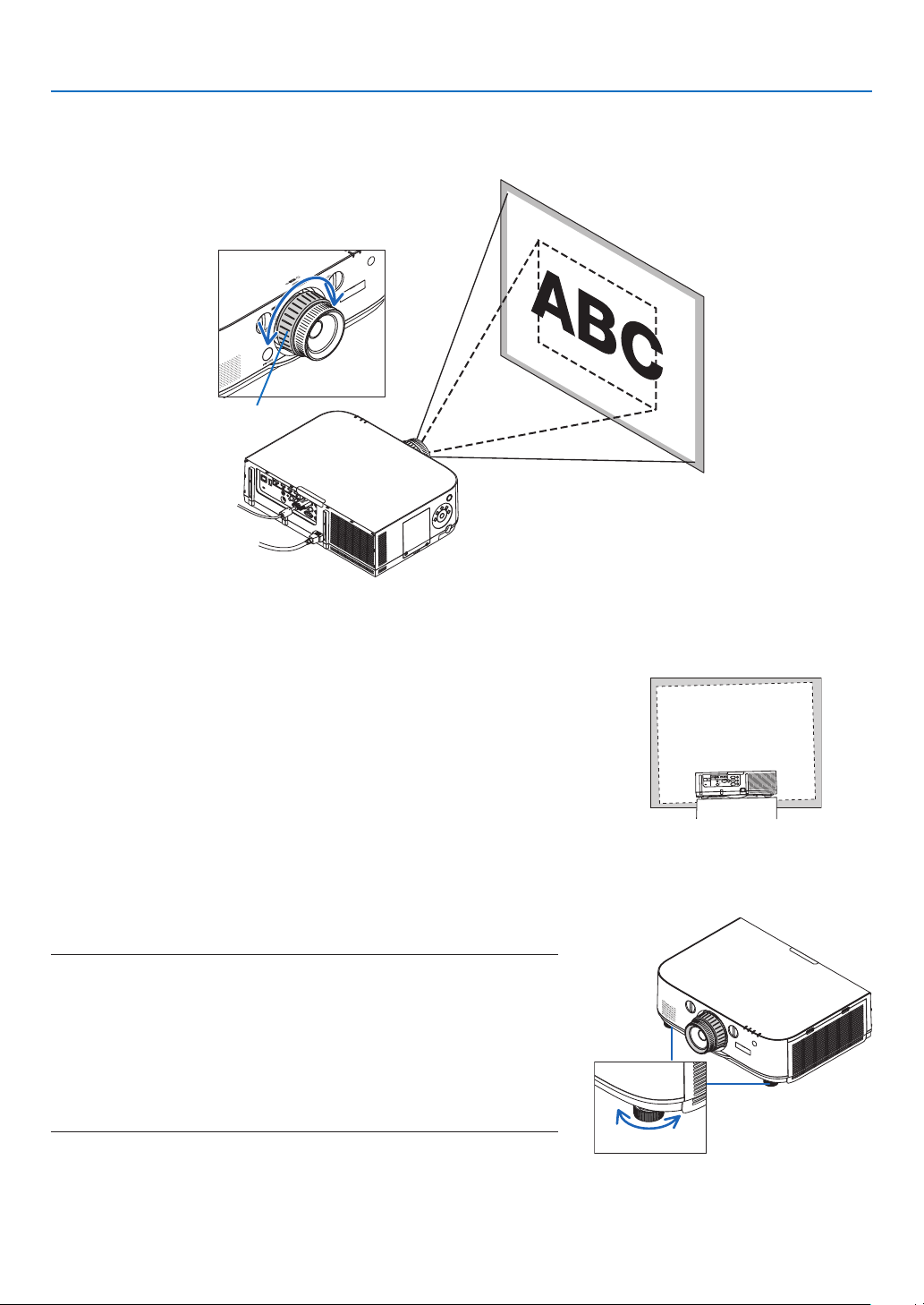
Applicable lens: NP11FL
WiththeNP11FLlens,adjustthefocusandpicturedistortion.
Preparations:
Turnthelensshiftdials(verticalandhorizontal)ontheprojectortoreturnthelensshifttothecenter.
Approximatelenscenterposition(explainedhereforthedesktopfrontprojectionmode)
Horizontal dial �������� First turn the dial to the left edge, then turn it further so that the knob is horizontal� From this position, turn
the dial 1 full turn clockwise�
Vertical dial ������������ First turn the dial to the bottom edge, then turn it further so that the knob is horizontal�
From this position, turn the dial 2 full turns counterclockwise�
1. Turn the distortion ring to the left edge.
Distortionring
Lensshiftdials
2. Turn the focus lever clockwise and counterclockwise
to adjust the focus at the center of the screen.
Focuslever
3. Use the distortion ring to correct the screen’s distor-
tion.
(Thisalsobringstheedgesofthescreenintofocus.)
4. Use the focus lever to adjust the screen’s overall fo-
cus.
* Ifthefocusatthecenterofthescreenisoff,turnthe
distortionringalittlecounterclockwise.Thefocusatthe
centerofthescreencannowbeadjustedwiththefocus
lever.
23
2. Projecting an Image (Basic Operation)
Adjusting the Tilt Feet
1. Turn the left and right tilt feet to adjust.
Thetiltfeetlengthenandshortenwhenturned.
Theheightoftheprojectedimageisadjustedbyturningtheleftand
righttiltfeet.
Iftheprojectedimageistilted,turnoneofthetiltfeettoadjustthe
imagesothatitislevel.
• Iftheprojectedimageisdistorted,see“3-6CorrectingHorizontal
andVerticalKeystoneDistortion[CORNERSTONE]”(→page33)
and“[GEOMETRICCORRECTION]”(→page87).
• Thetiltfeetcanbelengthenedbyamaximumof20mm.
• Thetiltfeetcanbeusedtotilttheprojectorbyamaximumof4º.
NOTE:
• Donotlengthenthetiltfeetanymorethan20mm/0.8".Doingsowillmakethe
tiltfeet’smountsectionunstableandcouldcausethetiltfeettocomeoffthe
projector.
• Donotuse thetiltfeet foranypurposeother thanadjustingtheprojector’s
projection angle.
Handlingthetiltfeetimproperly,suchascarryingtheprojectorbygraspingthe
tilt feet or hooking it onto a wall using the tilt feet, could damage the projec-
tor.
Zoom
Turnthezoomleverorzoomringclockwiseandcounterclockwise.
• TheseparatelysoldNP11FLlensdoesnothaveazoomring.
Zoomring
Up
Tiltfoot
Down
24
2. Projecting an Image (Basic Operation)
❻ Optimizing Computer Signal Automatically
Adjusting the Image Using Auto Adjust
Optimizingacomputerimageautomatically.(COMPUTER/BNC(AnalogRGB))
PresstheAUTOADJ.buttontooptimizeacomputerimageautomatically.
Thisadjustmentmaybenecessarywhenyouconnectyourcomputerforthersttime.
[Poorpicture]
[Normalpicture]
NOTE:
Somesignalsmaytaketimetodisplayormaynotbedisplayedcorrectly.
• IftheAutoAdjustoperationcannotoptimizethecomputersignal,trytoadjust[HORIZONTAL],[VERTICAL],[CLOCK],and[PHASE]
manually. (→ page 78, 79)
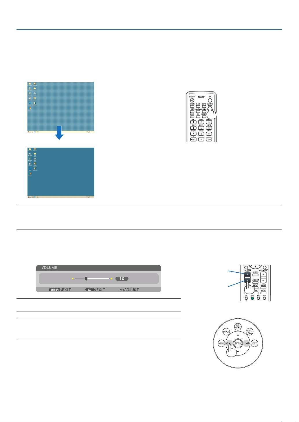
❼ Turning Up or Down Volume
Soundlevelfromthespeakercanbeadjusted.
TIP:Whennomenusappear,the◀ and ▶ buttons on the projector cabinet work
as a volume control.
NOTE:
• Volumecontrolisnotavailablewiththe◀ or ▶ button when an image is enlarged
byusingtheD-ZOOM(+)buttonorwhenthemenuisdisplayed.
Increasevolume
Decreasevolume
25
2. Projecting an Image (Basic Operation)
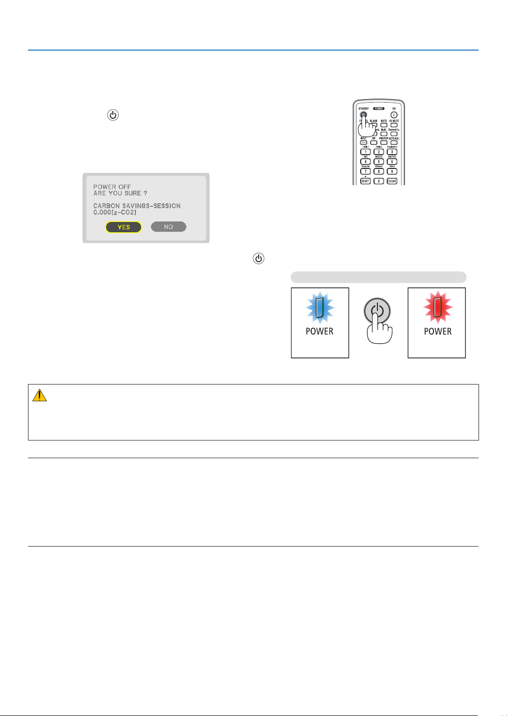
❽ Turning off the Projector
To turn off the projector:
1. First, press the (POWER) button on the projector
cabinet or the POWER OFF button on the remote con-
trol.
The[POWEROFF/AREYOUSURE?/CARBONSAV-
INGS-SESSION0.000[g-CO2]]messagewillappear.
2. Secondly, press the ENTER button or press the
(POWER) or the POWER OFF button again.
Thelampwillgooffandthepowersupplywillbecut.At
thispoint,iftherearenoinputsignals,theprojectorwillgo
into the standby mode after about 10 seconds.When in
standbymode,thePOWERindicatorwilllightredandthe
STATUSindicatorwilllightoffwhen[NORMAL]isselected
for[STANDBYMODE].
Power On
Steady blue light
Standby
Steady red light
Press twice
CAUTION:
PartsoftheprojectormaybecometemporarilyheatediftheprojectoristurnedoffwiththePOWERbuttonorifthe
ACpowersupplyisdisconnectedduringnormalprojectoroperation.
Usecautionwhenpickinguptheprojector.
NOTE:
• WhilethePOWERindicatorisblinkingblueinshortcycles,thepowercannotbeturnedoff.
• Youcannotturnoffthepowerfor60secondsimmediatelyafterturningitonanddisplayinganimage.
• Donotunplugthepowercordfromtheprojectororfromthepoweroutletwhileanimageisbeingprojected.Doingsocould
deterioratetheprojector’sACinputconnectororthepowerplug’scontact.ToturnofftheACpowerwhileanimageisbeing
projected,usethepowerstrip’sswitch,thebreaker,etc.
• DonotdisconnecttheACpowersupplytotheprojectorwithin10secondsofmakingadjustmentorsettingchangesandclosing
themenu.Doingsocancauselossofadjustmentsandsettings.

26
2. Projecting an Image (Basic Operation)
❾ After Use
Preparation:Makesurethattheprojectoristurnedoff.
1. Unplug the power cord.
2. Disconnect any other cables.
3. Mount the lens cap on the lens.
4. Before moving the projector, screw in the tilt feet if they have been lengthened.
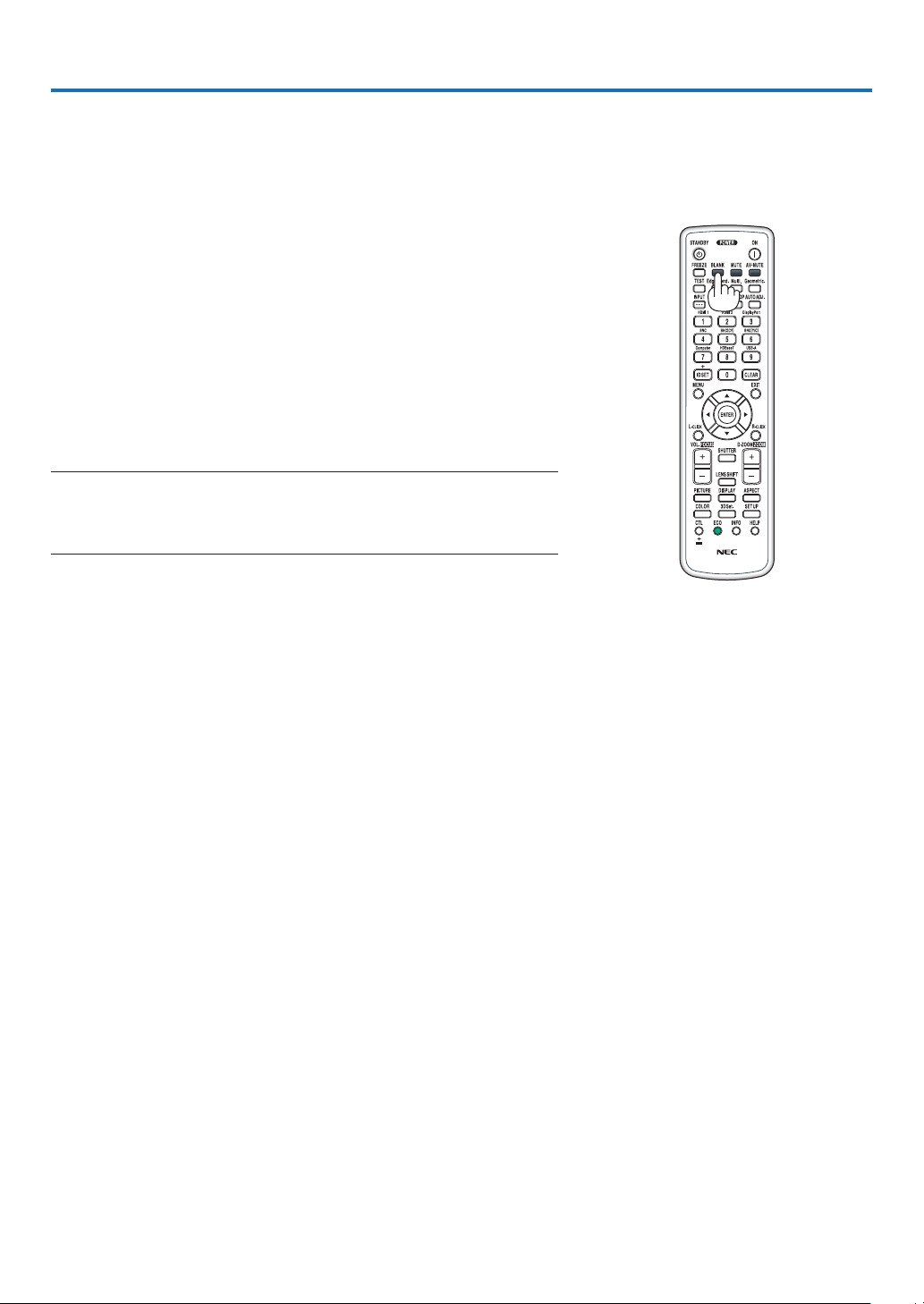
27
❶ Turning off the Image and Sound
Theprojectedvideoandtheoutputsoundfromtheinternalspeakerand
soundoutputterminalwilldisappearmomentarily.
PresstheBLANKbutton.
Theprojectedvideowillbecutoff.
Press the MUTE button.
Theprojectedaudiowillbecutoff.
PresstheAV-MUTEbutton.
Theprojectedvideoandaudiowillbecutoff.
• Pressthebuttonsonemoretimeforthecancelledvideoandaudioto
appearagain.
WhenAV-MUTEandBLANKarecontinuedforsometime,theenergy-
savingfunctionwillactivatetolowerthelamppower.
NOTE:
• When the AV-MUTE and BLANK buttons are pressed immediately after the
energy-saving function is activated, sometimes the brightness may not return
to normal immediately.
TIP:
• Thevideowilldisappearbutnotthemenudisplay.
3. Convenient Features
28
3. Convenient Features
❷ Freezing a Picture
PresstheFREEZEbuttonto freezeapicture.Pressagain to resume
motion.
NOTE: The image is frozen but the original video is still playing back.
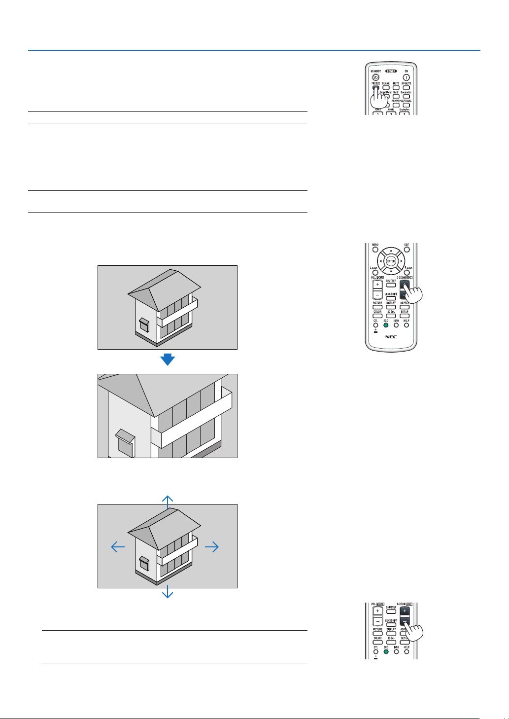
❸ Enlarging a Picture
Youcanenlargethepictureuptofourtimes.
NOTE:Themaximummagnicationmaybelessthanfourtimesdependingon
the signal.
Todoso:
1. Press the D-ZOOM (+) button to magnify the picture.
2. Press the ▲▼◀▶ button.
Theareaofthemagniedimagewillbemoved
3. Press the D-ZOOM (−) button.
EachtimetheD-ZOOM(−)buttonispressed,theimageisreduced.
NOTE:
• Theimagewillbeenlargedorreducedatthecenterofthescreen.
• Displayingthemenuwillcancelthecurrentmagnication.

29
3. Convenient Features
❹ Changing Eco Mode/Checking Energy-Saving Effect Using Eco
Mode [ECO MODE]
Thisfeatureenablesyoutoselecttwobrightnessmodesofthelamp:
OFFandONmodes.Thelamplifecanbeextendedbyturningonthe[ECOMODE].
[ECOMODE] Description
[OFF]
Thisisthedefaultsetting(100%Brightness).
[ON] Lowlamppowerconsumption(approx.80%Brightness).
Toturnonthe[ECOMODE],dothefollowing:
1. PresstheECObuttonontheremotecontroltodisplay[ECOMODE]screen.
2. Use the ▲ or ▼buttontoselect[ON].
3. Press the ENTER button.
Tochangefrom[ON]to[OFF],GobacktoStep2andselect[OFF].RepeatStep3.
NOTE:
• The[ECOMODE]canbechangedbyusingthemenu.
Select[SETUP]→[INSTALLATION]→[LAMPMODE]→[ECOMODE].
• Thelampliferemainingandlamphoursusedcanbecheckedin[USAGETIME].Select[INFO.]→[USAGETIME].
• [ECOMODE]isalwayssetto[OFF]for1minuteimmediatelyafterthelampisturnedon.Thelampconditionwillnotbeaffected
evenwhen[ECOMODE]ischanged.
• Afteralapseof1minutefromwhentheprojectordisplaysablue,blackorlogoscreen,[ECOMODE]willautomaticallyswitchto
[ON].
• Iftheprojectorisoverheatedin[OFF]mode,theremaybeacasewherethe[ECOMODE]automaticallychangesto[ON]mode
toprotecttheprojector.Thisiscalled“ForcedECOMode”.WhentheprojectorisintheForcedEcoMode,thepicturebrightness
decreasesslightlyandtheTEMP.indicatorlightsorange.AtthesametimetheThermometersymbol[ ]isdisplayedatthebot-
tom right of the screen.
Whentheprojectorcomesbacktonormaltemperature,theForcedEcoModeiscancelledandthe[ECOMODE]returnsto[OFF]
mode.
30
3. Convenient Features
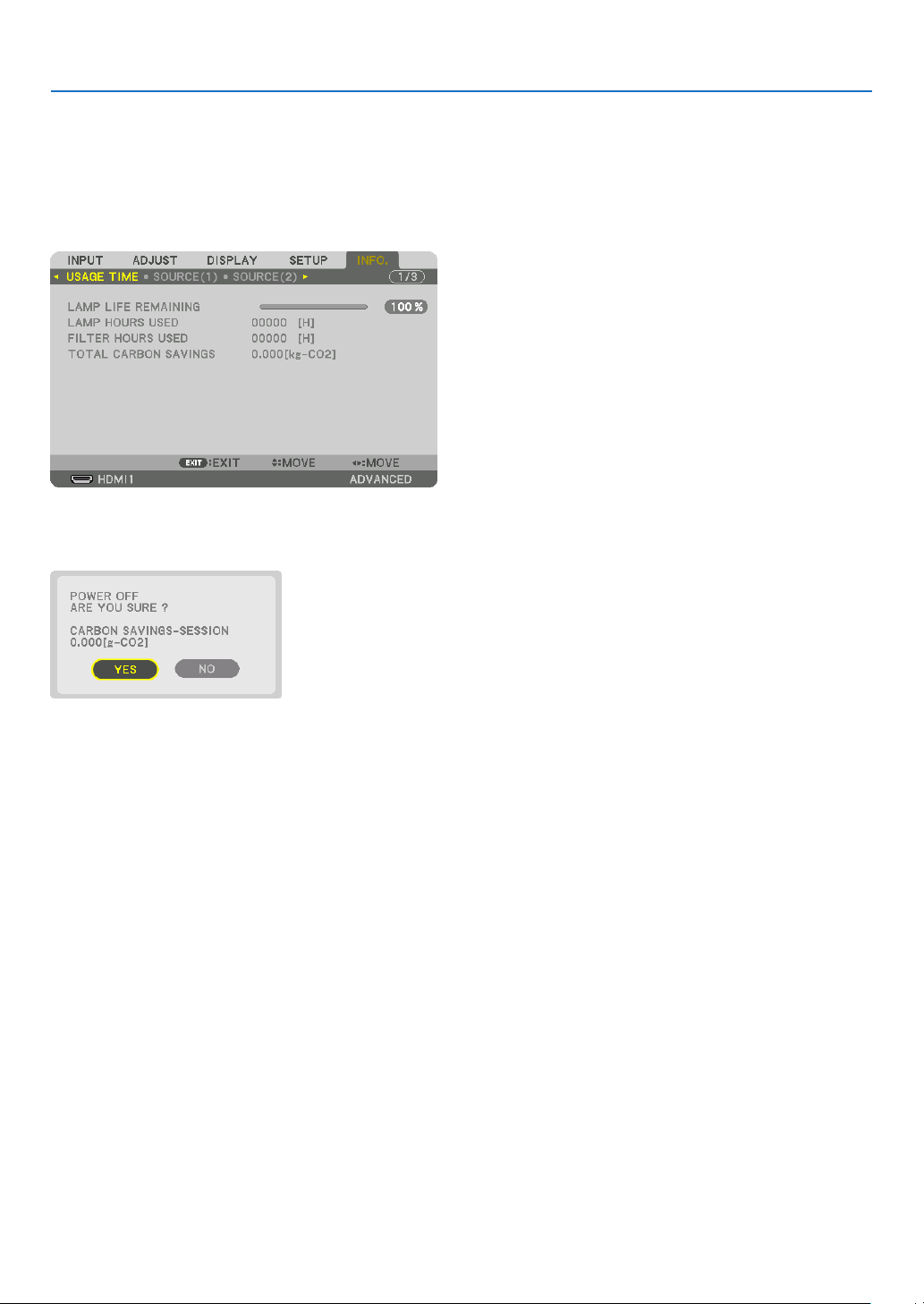
Checking Energy-Saving Effect [CARBON METER]
Thisfeaturewillshowenergy-savingeffectintermsofCO
2
emissionreduction(kg)whentheprojector’s[ECOMODE]
issetto[OFF],or[ON].Thisfeatureiscalledas[CARBONMETER].
Therearetwomessages:[TOTALCARBONSAVINGS]and[CARBONSAVINGS-SESSION].The[TOTALCARBON
SAVINGS]messageshowsthetotalamountofCO
2
emissionreductionfromthetimeofshipmentuptonow.Youcan
checktheinformationon[USAGETIME]from[INFO.]ofthemenu.(→page118)
The[CARBONSAVINGS-SESSION]messageshowstheamountofCO
2
emissionreductionbetweenthetimeof
changingtoECOMODEimmediatelyafterthetimeofpower-onandthetimeofpower-off.The[CARBONSAVINGS-
SESSION]messagewillbedisplayedinthe[POWEROFF/AREYOUSURE?]messageatthetimeofpower-off.
TIP:
• TheformulaasshownbelowisusedtocalculatetheamountofCO
2
emission reduction.
AmountofCO
2
emissionreduction=(PowerconsumptioninOFFforECOMODE−PowerconsumptioninONforECOMODE)×
CO
2
conversionfactor.*WhentheimageisturnedoffwiththeAV-MUTEbuttontheamountofCO
2
emmission reduction will also
increase.
* CalculationforamountofCO
2
emissionreductionisbasedonanOECDpublication“CO
2
EmissionsfromFuelCombustion,
2008Edition”.
• The[TOTALCARBONSAVINGS]iscalculatedbasedonsavingsrecordedin15minutesintervals.
• Thisformulawillnotapplytothepowerconsumptionwhichisnotaffectedbywhether[ECOMODE]isturnedonoroff.
31
3. Convenient Features
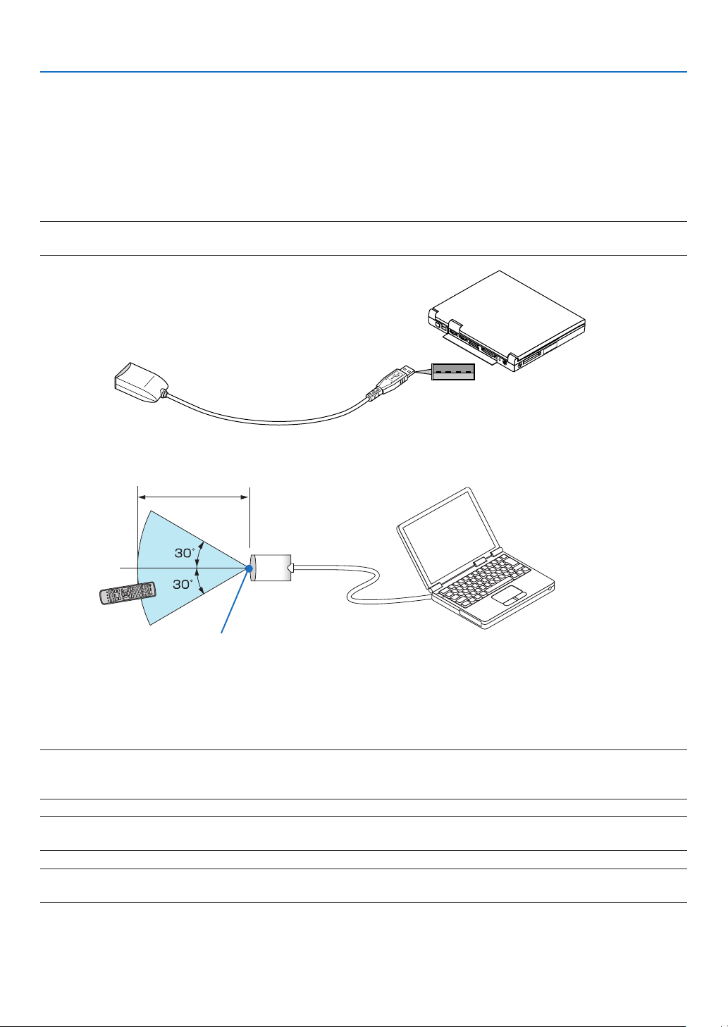
❺ Using the Optional Remote Mouse Receiver (NP01MR)
Theoptionalremotemousereceiverenablesyoutooperateyourcomputer’smousefunctionsfromtheremotecontrol.
Itisagreatconvenienceforclickingthroughyourcomputer-generatedpresentations.
Connectingtheremotemousereceivertoyourcomputer
Ifyouwishtousetheremotemousefunction,connectthemousereceiverandcomputer.
Themousereceivercanbeconnecteddirectlytothecomputer’sUSBport(typeA).
NOTE:DependingonthetypeofconnectionorOSinstalledonyourcomputer,youmayhavetorestartyourcomputerorchange
your computer settings.
When operating a computer via the remote mouse receiver
When connecting using the USB terminal
ForPC,themousereceivercanonlybeusedwithaWindowsXP*,WindowsVista,Windows7,orMacOSX10.0.0
orlateroperatingsystem.
*NOTE:InSP1orolderversionofWindowsXP,ifthemousecursorwillnotmovecorrectly,dothefollowing:
CleartheEnhancepointerprecisioncheckboxunderneaththemousespeedsliderintheMousePropertiesdialogbox[Pointer
Optionstab].
NOTE:WhenusingPowerPointforMacOS,theCTLbuttonandthepage▼/▲ buttons (page up and down) on the remote control
will be disabled.
NOTE:Waitatleast5secondsafterdisconnectingthemousereceiverbeforereconnectingitandviceversa.Thecomputermaynot
identify the mouse receiver if it is repeatedly connected and disconnected in rapid intervals.
Remotemousereceiver
Computer
ToUSBportofPCorMac
Remotesensoronthe
remotemousereceiver
7m/22feet

32
3. Convenient Features
Operatingyourcomputer’smousefromtheremotecontrol
Youcanoperateyourcomputer’smousefromtheremotecontrol.
CTL Button + PAGE ▼/▲ Button
������������������������������ scrolls the viewing area of the window or to move to the previous or next slide in PowerPoint on your
computer�
▲▼◀▶ Buttons ���� moves the mouse cursor on your computer�
L-CLICK Button ������ works as the mouse left button�
R-CLICK Button ����� works as the mouse right button�
NOTE:
• Whenyouoperatethecomputerusingthe▲▼◀ or ▶ button with the menu displayed, both the menu and the mouse pointer
willbeaffected.Closethemenuandperformthemouseoperation.
• WhenusingPowerPointforMacOS,theCTLbuttonandthepage▼/▲ buttons (page up and down) on the remote control will
be disabled.
About Drag Mode:
BypressingtheL-CLICKorR-CLICKbuttonfor2or3secondsthenreleasing,thedragmodeissetandthedrag
operationcanbeperformedsimplybypressingthe▲▼◀▶button.Todroptheitem,presstheL-CLICK(orR-CLICK)
button.Tocancelit,presstheR-CLICK(orL-CLICK)button.
TIP:YoucanchangethePointerspeedontheMousePropertiesdialogboxontheWindows.Formoreinformation,seetheuser
documentation or online help supplied with your computer.
33
3. Convenient Features
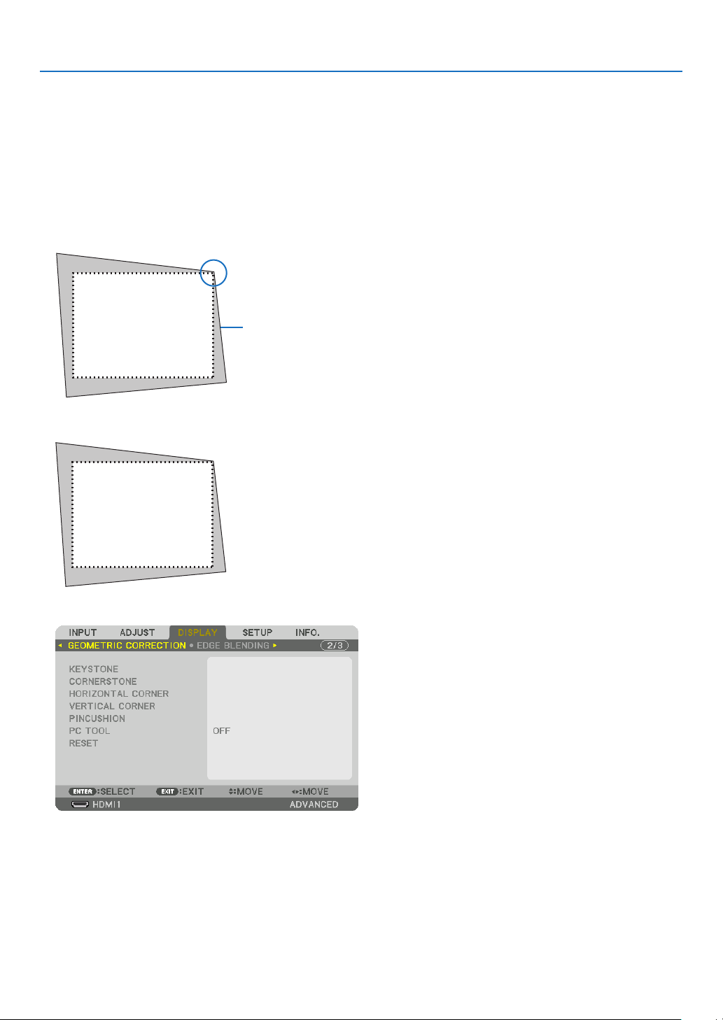
❻ Correcting Horizontal and Vertical Keystone Distortion [COR-
NERSTONE]
Usethe[CORNERSTONE]featuretocorrectkeystone(trapezoidal)distortiontomakethetoporbottomandtheleft
orrightsideofthescreenlongerorshortersothattheprojectedimageisrectangular.
1. Press and hold the Geometric. button for a minimum of 2 seconds to reset current adjustments.
Currentadjustmentsfor[GEOMETRICCORRECTION]willbecleared.
2. Project an image so that the screen is smaller than the area of the raster.
Projectedimage
Thedrawingshowstheupperrightcorner.
3. Pick up any one of the corners and align the corner of the image with a corner of the screen.
4. Press the Geometric. button.
Displaythe[GEOMETRICCORRECTION]screenoftheon-screenmenu.
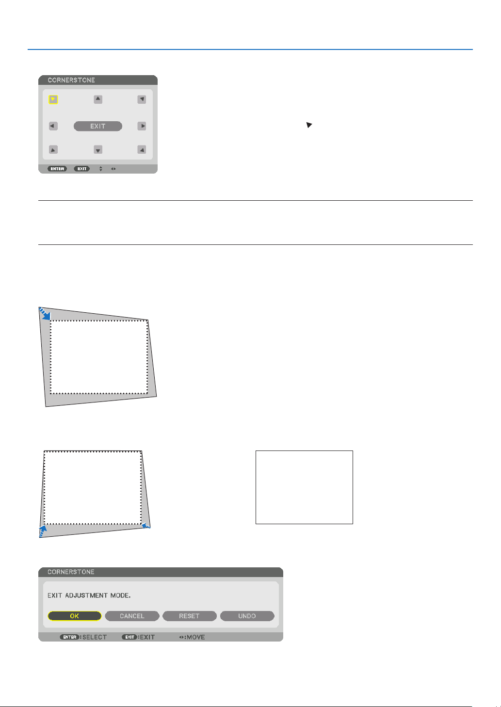
34
3. Convenient Features
5. Press the ▼buttontoalignwiththe[CORNERSTONE]andthenpresstheENTERbutton.
Thedrawingshowstheupperlefticon( )isselected.
Thescreenwillswitchtothe[CORNERSTONE]screen.
NOTE:
• Whena[GEOMETRICCORRECTION]functionotherthan[CORNERSTONE]hasbeensetup,the[CORNERSTONE]screenwill
notbedisplayed.Whenthescreenisnotdisplayed,eitherpresstheGeometric.buttonfor2ormoreseconds,orrun[RESET]
in[GEOMETRICCORRECTION]tocleartheadjustmentvalueof[GEOMETRICCORRECTION].
6. Use the ▲▼◀▶ button to select one icon (▲) which points in the direction you wish to move the projected
image frame.
7. Press the ENTER button.
8. Use the ▲▼◀▶ button to move the projected image frame as shown on the example.
9. Press the ENTER button.
10
. Use the ▲▼◀▶ button to select another icon which points in the direction.
Onthe[CORNERSTONE]screen,select[EXIT]orpresstheEXITbuttonontheremotecontrol.
Theconrmationscreenisdisplayed.

35
3. Convenient Features
11
. Press the ◀ or ▶buttontohighlightthe[OK]andpresstheENTERbutton.
Thiscompletesthe[CORNERSTONE]correction.
• Select[CANCEL]andpresstheENTERbuttontoreturntothe[CORNERSTONE]screen.
Selecting[CANCEL]willreturntotheadjustmentscreenwithoutsavingchanges(Step3).
Selecting[RESET]willreturntothefactorydefault.
Selecting[UNDO]willexitwithoutsavingchanges.
NOTE:
• Evenwhentheprojectoristurnedon,thelastusedcorrectionvaluesareapplied.
• Carryouteitheroneofthefollowingactionstocleartheadjustmentvalueof[CORNERSTONE].
• InStep11,select[RESET]andthenpresstheENTERbutton.
• PresstheGeometric.buttonfor2ormoreseconds.
• Run[DISPLAY]→[GEOMETRICCORRECTION]→[RESET]intheon-screenmenu.
• UsingCORNERSTONEcorrectioncancausetheimagetobeslightlyblurredbecausethecorrectionismadeelectronically.
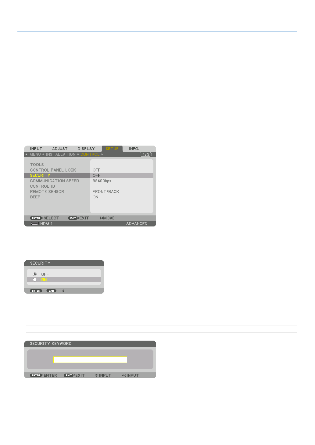
36
3. Convenient Features
❼
Preventing the Unauthorized Use of the Projector [SECURITY]
AkeywordcanbesetforyourprojectorusingtheMenutoavoidoperationbyanunauthorizeduser.Whenakeyword
isset,turningontheprojectorwilldisplaytheKeywordinputscreen.Unlessthecorrectkeywordisentered,thepro-
jectorcannotprojectanimage.
•The[SECURITY]settingcannotbecancelledbyusingthe[RESET]ofthemenu.
ToenabletheSecurityfunction:
1. Press the MENU button.
Themenuwillbedisplayed.
2. Press the ▶ buttontwice to select [SETUP] and press the ▼ button or the ENTER button to select
[MENU].
3. Press the ▶buttontoselect[CONTROL].
4. Press the ▼buttonthreetimestoselect[SECURITY]andpresstheENTERbutton.
TheOFF/ONmenuwillbedisplayed.
5. Press the ▼buttontoselect[ON]andpresstheENTERbutton.
The[SECURITYKEYWORD]screenwillbedisplayed.
6. Type in a combination of the four ▲▼◀▶ buttons and press the ENTER button.
NOTE: A keyword must be 4 to 10 digits in length.
The[CONFIRMKEYWORD]screenwillbedisplayed.
NOTE:Makeanoteofyourpasswordandstoreitinasafeplace.
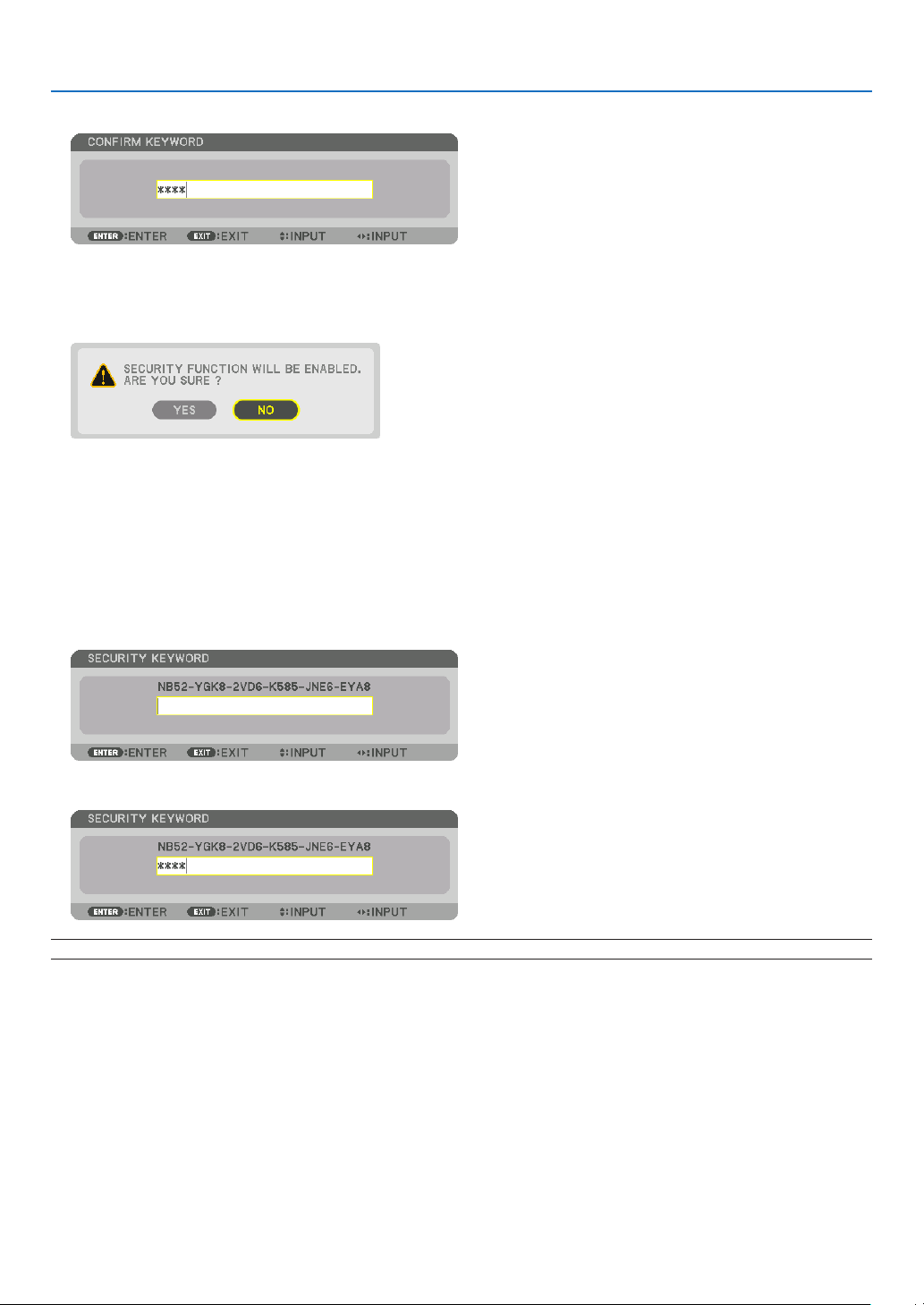
37
3. Convenient Features
7. Type in the same combination of ▲▼◀▶ buttons and press the ENTER button.
Theconrmationscreenwillbedisplayed.
8. Select[YES]andpresstheENTERbutton.
TheSECURITYfunctionhasbeenenabled.
To turn on the projector when [SECURITY] is enabled:
1. Press the POWER button.
Theprojectorwillbeturnedonanddisplayamessagetotheeffectthattheprojectorislocked.
2. Press the MENU button.
3. Type in the correct keyword and press the ENTER button. The projector will display an image.
NOTE: The security disable mode is maintained until the main power is turned off or unplugging the power cord.
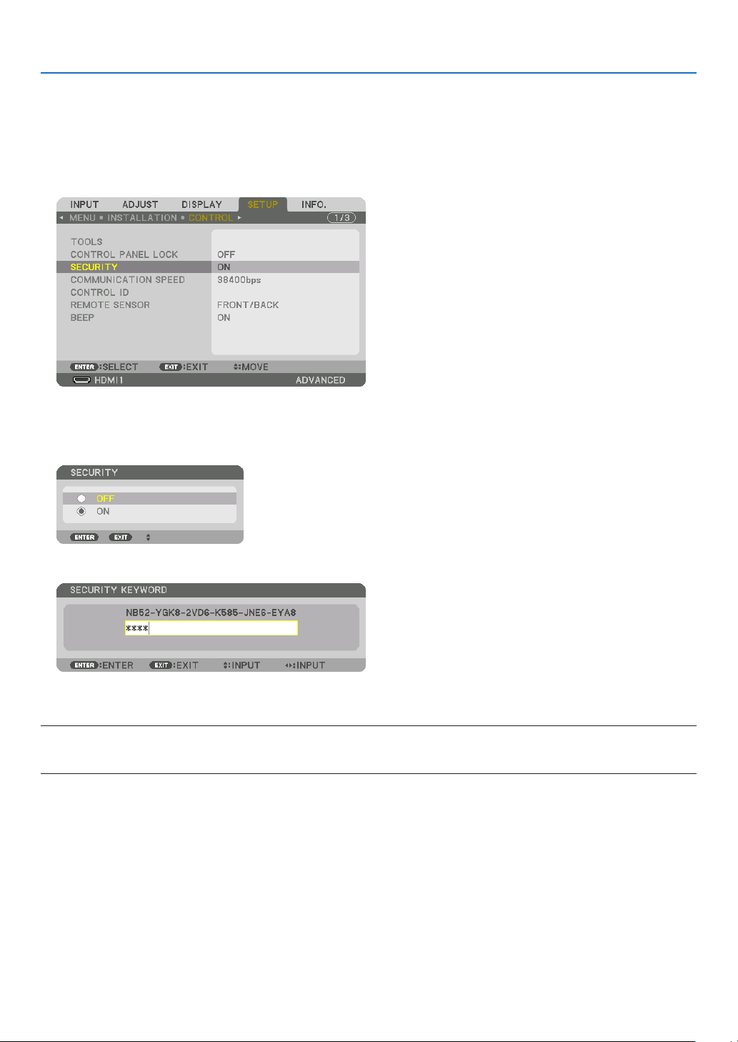
38
3. Convenient Features
To disable the SECURITY function:
1. Press the MENU button.
Themenuwillbedisplayed.
2.Select[SETUP]→[CONTROL]→[SECURITY]andpresstheENTERbutton.
TheOFF/ONmenuwillbedisplayed.
3. Select[OFF]andpresstheENTERbutton.
TheSECURITYKEYWORDscreenwillbedisplayed.
4. Type in your keyword and press the ENTER button.
Whenthecorrectkeywordisentered,theSECURITYfunctionwillbedisabled.
NOTE:Ifyouforgetyourkeyword,contactyourdealer.Yourdealerwillprovideyouwithyourkeywordinexchangeforyourrequest
code.YourrequestcodeisdisplayedintheKeywordConrmationscreen.Inthisexample[NB52-YGK8-2VD6-K585-JNE6-EYA8]
is a request code.

39
3. Convenient Features
❽ Projecting 3D videos
Thisprojectorcanbeusedtowatchvideosin3Dusingcommercially-availableactiveshutter-type3Deyewear.In
ordertosynchronizethe3Dvideoandeyewear,acommercially-available3Demitterneedstobeconnectedtothe
projector(ontheprojectorside).
The3Deyewearreceivesinformationfromthe3Demitterandperformsopeningandclosingontheleftandright.
CAUTION
Health precautions
Beforeuse,pleasemakesuretoreadanyhealthprecautionsthatmaybestatedintheoperatingmanualsenclosed
withthe3Deyewearand3Dvideosoftware(Blu-rayplayer,games,computeranimationles,etc.).
Pleasetakenoteofthefollowinginordertoavoidadversehealtheffects.
• Pleasedonotusethe3Deyewearforpurposesotherthantowatch3Dvideos.
• Pleasekeepadistanceofatleast2mawayfromthescreenwhenwatchingvideos.Watchingavideotooclose
tothescreenwillincreaseeyefatigue.
• Pleasedonotwatchvideoscontinuouslyforalongperiodoftime.Pleasetakea15minutes’breakafterevery
hourofwatching.
• Pleaseconsultadoctorbeforewatchingifyouoranyofyourfamilymembershaveahistoryofsufferingfrom
seizurescausedbylightsensitivity.
• Pleasestopwatchingimmediatelyandtakearestwhenyoufeelphysicallyunwellwhilewatching(vomiting,gid-
diness,nausea,headaches,soreeyes,blurredvision,crampsanddumbnessinthelimbs,etc.).Pleaseconsult
adoctorifthesymptomspersist.
• Pleasewatcha3Dvideodirectlyinfrontofthescreen.Ifyouwatcha3Dvideoobliquelyfromthesides,thismay
resultinphysicalandeyefatigue.
3Deyewearand3Demitterpreparations
Pleaseuseanactiveshutter-type3DeyewearthatconformswiththeVESAstandard.
Acommercially-availableRFtypemadebyXpandisrecommended.
3D eyewear ������������ Xpand X105-RF
3D emitter Xpand
��� AD025-RF-X1
Procedure to watch 3D videos using this projector
1. Connectthevideodevicetotheprojector.
2. Switch on the power supply to the projector.
3. Run the 3D video software and project the video using the projector.
Thishasbeenautomaticallysetupwhenshippedfromthefactory.Whena3Dvideocannotbeprojected,itmay
bebecausethe3Ddetectionsignalsarenotincludedorbecausetheyarenotdetectablebytheprojector.
Pleasemanuallyselecttheformat.
4. Select the 3D video format.
(1)Pressthe“3DSet.”buttonontheremotecontrol.
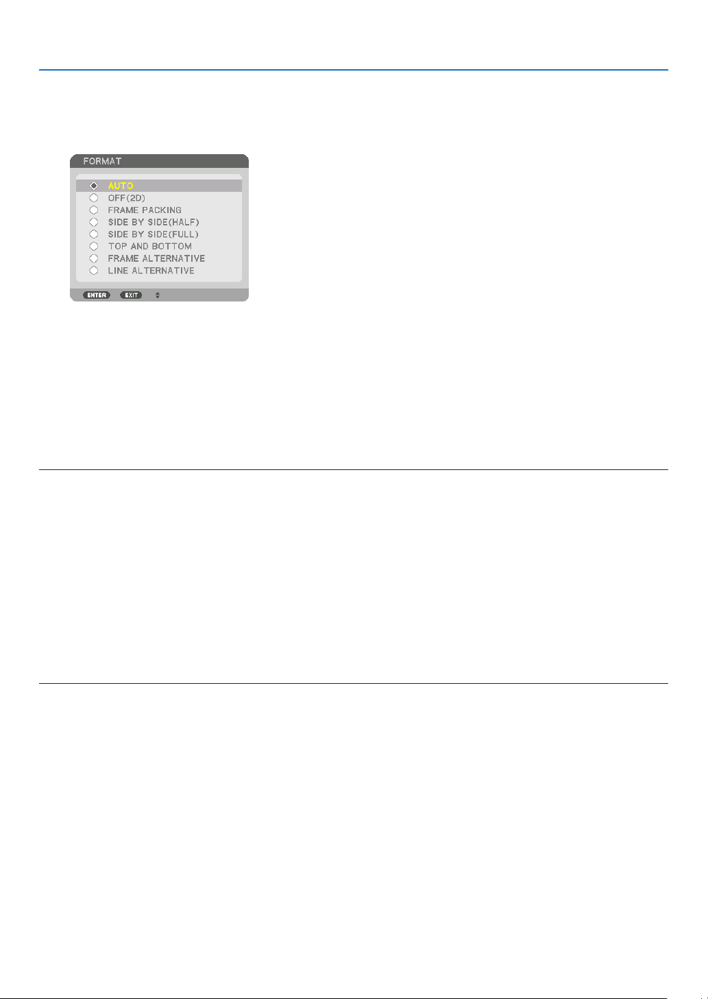
40
3. Convenient Features
The[3DSETTINGS]screenwillbedisplayed.
(2)Pressthe▼buttontoalignthecursorwiththe[FORMAT]andpresstheENTERbutton.
Theformatscreenwillbedisplayed.
(3)Selecttheinputsignalformatusingthe▼buttonandthenpresstheENTERbutton.
The3Dsettingsscreenwilldisappearandthe3Dvideowillbeprojected.
PresstheMENUbuttonandtheon-screenmenuwilldisappear.
The3D caution message screen willbedisplayedwhen switchingto a 3D video (defaultfactory setting when
shipped).Pleasereadthe“HealthPrecautions”onthepreviouspagetowatchvideosinthecorrectmanner.The
screenwilldisappearafter60secondsorwhentheENTERbuttonispressed.(→page95)
5. Turn on the power supply of the 3D eyewear and wear the eyewear to watch the video.
Anormalvideowillbeshownwhena2Dvideoisinput.
Towatcha3Dvideoin2D,select[OFF(2D)]inthe[FORMAT]screenmentionedabovein(3).
NOTE:
• Uponswitchingto3Dimage,thefollowingfunctionswillbecancelledanddisabled.[BLANKING],[PIP/PICTUREBYPICTURE],
[GEOMETRICCORRECTION],[EDGEBLENDING]([GEOMETRICCORRECTION]and[EDGEBLENDING]adjustmentvalueswill
be maintained.)
• Theoutputmaynotautomaticallyswitchtoa3Dvideodependingonthe3Dinputsignal.
• ChecktheoperatingconditionsdescribedintheusermanualoftheBlu-rayplayer.
• PleaseconnecttheDINterminalofthe3Demittertothe3DSYNCofthemainprojector.
• The3Deyewearallowsvideostobeviewedin3Dbyreceivingsynchronizedopticalsignalsoutputfromthe3Demitter.
Asaresult,the3Dimagequalitymaybeaffectedbyconditionssuchasthebrightnessofthesurroundings,screensize,viewing
distance, etc.
• Whenplayinga3Dvideosoftwareonacomputer,the3DimagequalitymaybeaffectedifthecomputerCPUandgraphicschip
performance are low. Please check the required operating environment of the computer that is stated in the operating manual
attachedtothe3Dvideosoftware.
• Dependingonthesignal,[FORMAT]and[L/RINVERT]maynotbeabletobeselected.Pleasechangethesignalinthatcase.

41
3. Convenient Features
When videos cannot be viewed in 3D
Pleasecheckthefollowingpointswhenvideoscannotbeviewedin3D.
Pleasealsoreadtheoperatingmanualattachedtothe3Deyewear.
Possible reasons Solutions
The selected signal does not support 3D output� Please change the video signal input to one that supports 3D�
The format for the selected signal is turned to [OFF(2D)]� Please change the format in the on-screen menu to [AUTO] or a
format that supports 3D�
A eyewear that is not supported by the projector is being used� Please purchase a commercially-available 3D eyewear or 3D emitter
(recommended)� (→ page 39)
Please check the following points when a video cannot be viewed in
3D using a 3D eyewear that is supported by the projector�
The power supply of the 3D eyewear is turned off� Please turn on the power supply of the 3D eyewear�
The internal battery of the 3D eyewear is flat� Please charge or replace the battery�
The viewer is located too far away from the screen� Please get closer to the screen until the video can be seen in 3D�
Please turn the L/R INVERT in the on-screen menu to [OFF]�
Due to multiple 3D projectors working at the same time in the vi-
cinity, the projectors may interfere with one another� Alternatively,
there may be a bright light source near the screen�
Please maintain sufficient distance between the projectors�
Please keep the light source away from the screen�
Please turn the L/R INVERT in the on-screen menu to [OFF]�
There is an obstacle between the optical receiver of the 3D eyewear
and the 3D emitter�
Please remove the obstacle�
The 3D format of the 3D video contents is not supported� Please check with the company selling the 3D video contents�

42
3. Convenient Features
❾ Controlling the Projector by Using an HTTP Browser
Overview
TheHTTPServerfunctionprovidessettingsandoperationsfor:
1. Settingforwirednetwork(NETWORKSETTINGS)
TousewiredLANconnection,connecttheprojectortothecomputerwithacommerciallyavailableLANcable.(→
page137)
2. Setting Alert Mail (ALERT MAIL)
Whentheprojectorisconnectedtoawirednetwork,lampreplacetimeorerrormessageswillbesentviae-mail.
3. Operating the projector
Poweron/off,selectinginput,volumecontrolandpictureadjustmentsarepossible.
4. SettingPJLinkPASSWORDandAMXBEACON
AccesstotheHTTPserverfunctionisavailable:
• StarttheWebbrowseronthecomputerviathenetworkconnectedtotheprojectorandenterthefollowing
URL :
http://<the projector’s IP address> /index.html
TIP:ThefactorysettingIPaddressis[DHCPON].
NOTE:
• Tousetheprojectorinanetwork,consultwithyournetworkadministratoraboutnetworksettings.
• Thedisplay’sorbutton’sresponsecanbesloweddownoroperationmaynotbeaccepteddependingthesettingsofyournet-
work.
Shouldthishappen,consultyournetworkadministrator.Theprojectormaynotrespondifitsbuttonsarerepeatedlypressedin
rapidintervals.Shouldthishappen,waitamomentandrepeat.Ifyoustillcan’tgetanyresponse,turnoffandbackontheprojec-
tor.
• IfthePROJECTORNETWORKSETTINGSscreendoesnotappearinthewebbrowser,presstheCtrl+F5keystorefreshyourweb
browser (or clear the cache).
• Thisprojectoruses“JavaScript”and“Cookies”andthebrowsershouldbesettoacceptthesefunctions.Thesettingmethodwill
varydependingontheversionofbrowser.Pleaserefertothehelplesandtheotherinformationprovidedinyoursoftware.
Preparation before Use
ConnecttheprojectortoacommerciallyavailableLANcablebeforeengaginginbrowseroperations.(→page137)
Operationwithabrowserthatusesaproxyservermaynotbepossibledependingonthetypeofproxyserverandthe
settingmethod.Althoughthetypeofproxyserverwillbeafactor,itispossiblethatitemsthathaveactuallybeenset
willnotbedisplayeddependingontheeffectivenessofthecache,andthecontentssetfromthebrowsermaynotbe
reectedinoperation.Itisrecommendedthataproxyservernotbeusedunlessitisunavoidable.
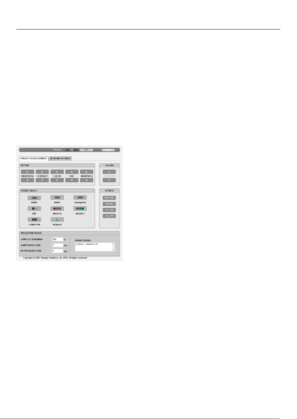
43
3. Convenient Features
Handling of the Address for Operation via a Browser
RegardingtheactualaddressthatisenteredfortheaddressorenteredtotheURLcolumnwhenoperationofthepro-
jectorisviaabrowser,thehostnamecanbeusedasitiswhenthehostnamecorrespondingtotheIPaddressofthe
projectorhasbeenregisteredtothedomainnameserverbyanetworkadministrator,orthehostnamecorresponding
totheIPaddressoftheprojectorhasbeensetinthe“HOSTS”leofthecomputerbeingused.
Example1:Whenthehostnameoftheprojectorhasbeensetto“pj.nec.co.jp”,accessisgainedtothenetwork
settingbyspecifying
http://pj.nec.co.jp/index.html
fortheaddressortheentrycolumnoftheURL.
Example2:WhentheIPaddressoftheprojectoris“192.168.73.1”,accessisgainedtothenetworksettingby
specifying
http://192.168.73.1/index.html
fortheaddressortheentrycolumnoftheURL.
PROJECTOR ADJUSTMENT
POWER:Thiscontrolsthepoweroftheprojector.
ON ������������������������� Power is switched on�
OFF ������������������������ Power is switched off�
VOLUME:Thiscontrolsthevolumeoftheprojector.
▲ ��������������������������� Increases the volume adjustment value�
▼ ��������������������������� Decreases the volume adjustment value�
AV-MUTE:Thiscontrolsthemutefunctionoftheprojector.
PICTURE ON ���������� Mutes the video�
PICTURE OFF ��������� Cancels the video muting�
SOUND ON ������������ Mutes the audio�
SOUND OFF ����������� Cancels the audio muting�
ALL ON ������������������ Mutes each of the video, and audio functions�
ALL OFF ����������������� Cancels the muting of each of the video, and audio functions�

44
3. Convenient Features
PICTURE:Controlsthevideoadjustmentoftheprojector.
BRIGHTNESS ▲ ���� Increases the brightness adjustment value�
BRIGHTNESS ▼ ���� Decreases the brightness adjustment value�
CONTRAST ▲ �������� Increases the contrast adjustment value�
CONTRAST ▼ �������� Decreases the contrast adjustment value�
COLOR ▲ �������������� Increases the color adjustment value�
COLOR ▼ �������������� Decreases the color adjustment value�
HUE ▲ ������������������� Increases the hue adjustment value�
HUE ▼ ������������������� Decreases the hue adjustment value�
SHARPNESS ▲ ����� Increases the sharpness adjustment value�
SHARPNESS ▼ ����� Decreases the sharpness adjustment value�
• Thefunctionsthatcanbecontrolledwillvarydependingonthesignalbeinginputtotheprojector.(→page76,
77)
SOURCESELECT:Thisswitchestheinputconnectoroftheprojector.
HDMI1 ������������������� Switches to the HDMI 1 IN connector�
HDMI2 ������������������� Switches to the HDMI 2 IN connector�
DisplayPort ������������ Switches to the DisplayPort�
BNC ����������������������� Switch to BNC (analog RGB) video input�
BNC(CV) ���������������� Switch to BNC (CV) video input�
BNC(Y/C) ��������������� Switch to BNC (Y/C) video input�
COMPUTER ����������� Switches to the COMPUTER IN connector�
HDBaseT ���������������� Switch to image input sent from a transmission device that supports HDBaseT�
PROJECTORSTATUS:Thisdisplaystheconditionoftheprojector.
LAMP LIFE REMAINING �����Displays the remaining life of the lamp as a percentage�
LAMP HOURS USED �����������Displays how many hours the lamp has been used�
FILTER HOURS USED ���������Displays how many hours the filter has been used�
ERROR STATUS ������������������Displays the status of errors occurring within the projector�
LOGOFF:Loggingoffyourprojectorandreturningtotheauthenticationscreen(LOGONscreen).

45
3. Convenient Features
NETWORK SETTINGS
•SETTINGS
WIRED
SETTING SetforwiredLAN.
APPLY ApplyyoursettingstowiredLAN.
PROFILE1/PROFILE2 TwosettingscanbesetforwiredLANconnection.SelectPROFILE1orPROFILE2.
DISABLE TurnoffwiredLANconnection
DHCPON AutomaticallyassignIPaddress,subnetmask,andgatewaytotheprojectorfromyour
DHCPserver.
DHCPOFF SetIPaddress,subnetmask,andgatewaytotheprojectorassignedbyyournetwork
administrator.
IPADDRESS SetyourIPaddressofthenetworkconnectedtotheprojector.
SUBNETMASK Setyoursubnetmasknumberofthenetworkconnectedtotheprojector.
GATEWAY Setthedefaultgatewayofthenetworkconnectedtotheprojector.
AUTODNSON DHCPserverwillautomaticallyassignIP address of DNS serverconnected to the
projector.
AUTODNSOFF SetyourIPaddressofDNSserverconnectedtotheprojector.

46
3. Convenient Features
•NAME
PROJECTORNAME Enteraname foryourprojector sothatyourcomputercan identify theprojector. A
projectornamemustbe16charactersorless.
TIP:Projectornamewillnotbeaffectedevenwhen[RESET]isdonefromthemenu.
HOSTNAME Enterthehostnameofthenetworkconnectedtotheprojector.Ahostnamemustbe
15orless.
DOMAINNAME Enterthedomainnameofthenetworkconnectedtotheprojector. Adomain name
mustbe60charactersorless.
•ALERTMAIL
ALERTMAIL Thisoptionwillnotifyyourcomputeroflampreplacetimeorerrormessagesviae-mail
whenusingwiredLAN.
PlacingacheckmarkwillturnontheAlertMailfeature.
ClearingacheckmarkwillturnofftheAlertMailfeature.
Sampleofamessagetobesentfromtheprojector:
Thelampandltersareattheendofitsusablelife.Pleasereplacethelampand
lters.
ProjectorName:NECProjector
LampHoursUsed:100[H]
SENDER’SADDRESS Entersender’saddress.
SMTPSERVERNAME EntertheSMTPservernametobeconnectedtotheprojector.
RECIPIENT’SADDRESS
1,2,3
Enteryourrecipient’saddress.Uptothreeaddressescanbeentered.
TESTMAIL Sendatestmailtocheckwhetheryoursettingsarecorrectornot
NOTE:
• Ifyouexecuteatest,youmaynotreceiveanAlertmail.Shouldthishappen,checkifnetwork
settings are correct.
• Ifyouenteredanincorrectaddressinatest,youmaynotreceiveanAlertmail.Shouldthis
happen,checkiftheRecipient’sAddressiscorrect.
SAVE Clickthisbuttontosaveyoursettingstotheprojector’smemory.

47
3. Convenient Features
•NETWORKSERVICE
PJLinkPASSWORD SetapasswordforPJLink*.Apasswordmustbe32charactersorless.Donotforget
yourpassword.However,ifyouforgetyourpassword,consultwithyourdealer.
HTTPPASSWORD SetapasswordforHTTPserver.Apasswordmustbe10charactersorless.
Whenapasswordissetup,youwillbepromptedforyourusername(arbitrary)and
passwordduringLOGON.
AMXBEACON TurnonorofffordetectionfromAMXDeviceDiscoverywhenconnectingtothenetwork
supportedbyAMX’sNetLinxcontrolsystem.
TIP:
WhenusingadevicethatsupportsAMXDeviceDiscovery,allAMXNetLinxcontrolsystemwillrec-
ognizethedeviceanddownloadtheappropriateDeviceDiscoveryModulefromanAMXserver.
PlacingacheckmarkwillenabledetectingtheprojectorfromAMXDeviceDiscovery.
ClearingacheckmarkwilldisabledetectingtheprojectorfromAMXDeviceDiscovery.
NOTE: If you forget your password, contact your dealer.
*WhatisPJLink?
PJLinkisastandardizationofprotocolusedforcontrollingprojectorsofdifferentmanufacturers.Thisstandardproto-
colisestablishedbyJapanBusinessMachineandInformationSystemIndustriesAssociation(JBMIA)in2005.
TheprojectorsupportsallthecommandsofPJLinkClass1.
SettingofPJLinkwillnotbeaffectedevenwhen[RESET]isdonefromthemenu.
•INFORMATION
WIREDLAN DisplayalistofsettingsofwiredLANconnection.
UPDATE Reectsettingswhentheyarechanged.
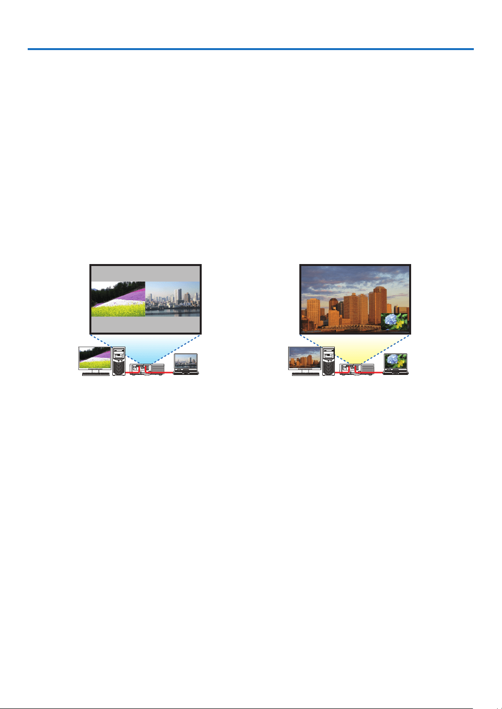
48
4. Multi-Screen Projection
❶ Things that can be done using multi-screen projection
Thisprojectorcanbeusedsinglyorarrangedinmultipleunitsformulti-screenprojection.
Wewillintroduceanexampleusingtwoprojectionscreenshere.
Case 1
Usingasingleprojectortoprojecttwotypesofvideosatthesametime
[PIP/PICTUREBYPICTURE]
Case 2
Usingfourprojectors(liquidcrystalpanel:XGA)toprojectvideowitharesolutionof1920×1080pixels
[TILING]
Case 1. Using a single projector to project two types of videos [PIP/PICTURE BY PIC-
TURE]
Connection example and projection image
Inthecaseof[PICTUREBYPICTURE] Inthecaseof[PIP]
On-screen menu operations
Display[DISPLAY]→[PIP/PICTUREBYPICTURE]→[MODE]screenintheon-screenmenuandselect[PIP]or
[PICTUREBYPICTURE].
Fordetails,pleasereferto“4-2DisplayingTwoPicturesattheSameTime”.(→page52)
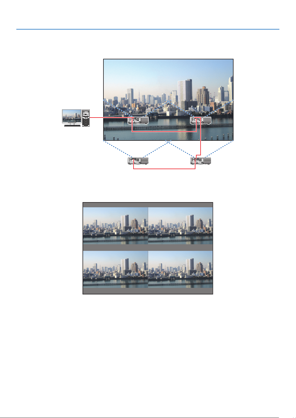
49
4. Multi-Screen Projection
Case 2. Using four projectors (liquid crystal panel: XGA) to project videos with a resolution
of 1920 × 1080 pixels [TILING]
Connection example and projection image
On-screen menu operations
1 Four similar videos are displayed when four projectors are projected.
Pleaserequesttheretailstoretoadjusttheprojectionpositionofeachprojector.
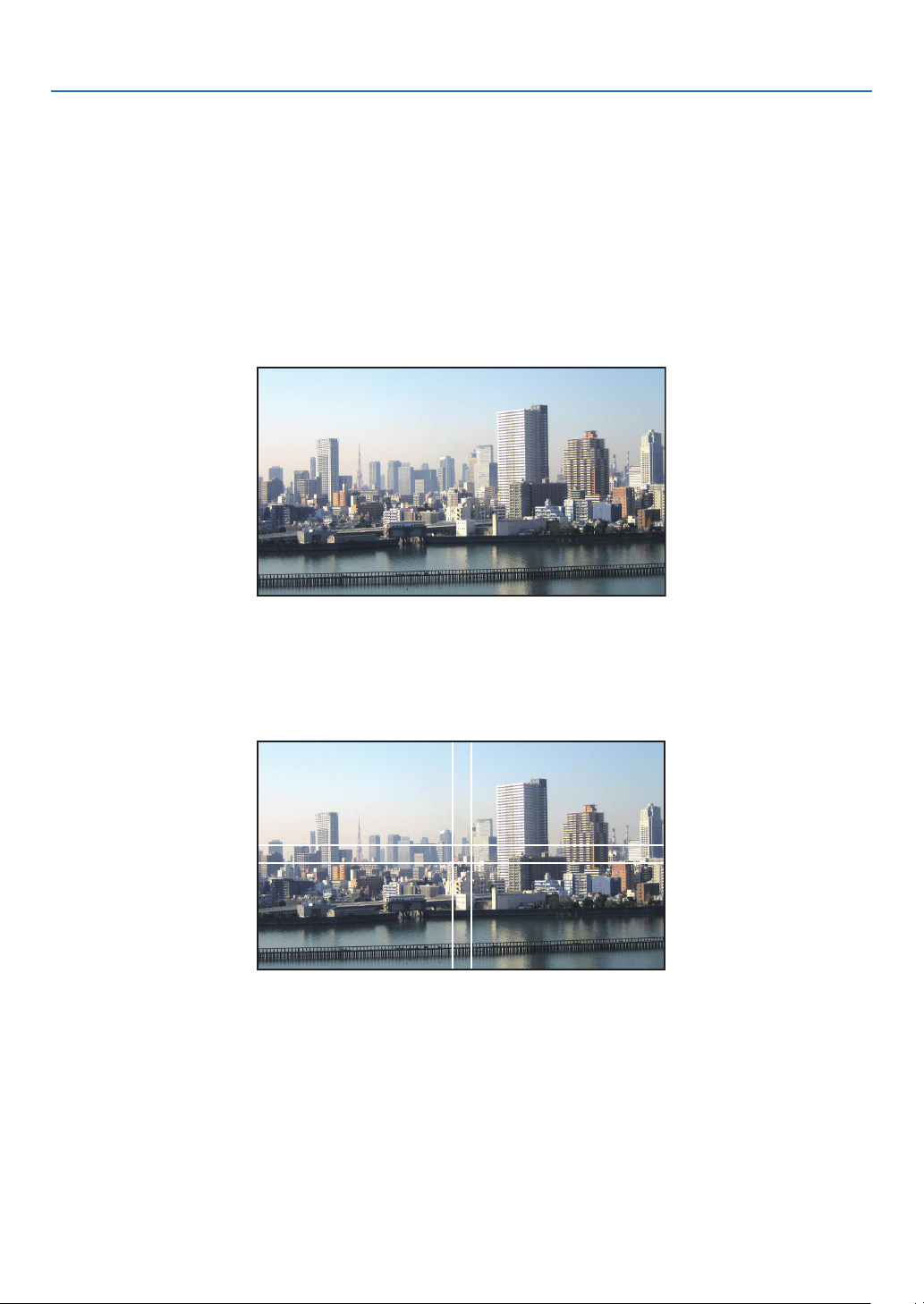
50
4. Multi-Screen Projection
2 Operate the on-screen menu using the four respective projectors to divide the image into four portions.
Display[DISPLAY]→[MULTISCREEN]→[PICTURESETTING]Screenintheon-screenmenuandselect[TIL-
ING].
(1)Inthescreenforsettingthenumberofhorizontalunits,select[2UNITS].(numberofunitsinthehorizontaldirec-
tion)
(2)Inthescreenforsettingthenumberofverticalunits,select[2UNITS].(numberofunitsintheverticaldirec-
tion)
(3)Inthescreenforsettingthehorizontalorder,select[1stUNIT]or[2ndUNIT].
(lookatthescreens,theoneontheleftisthe[1stUNIT]whiletheoneontherightisthe[2ndUNIT])
(4)Inthescreenforsettingtheverticalorder,selectthe[1stUNIT]orthe[2ndUNIT].
(lookatthescreens,theoneatthetopisthe[1stUNIT]whiletheoneatthebottomisthe[2ndUNIT])
3 Adjust the lens shift of each projector to fine-tune the boundaries of the screen.
Forfurtherne-tuning,adjustusing[DISPLAY]→[EDGEBLENDING]intheon-screenmenuforeachprojector.
Fordetails,pleasereferto“4-3DisplayingaPictureUsing[EDGEBLENDING]”.
(→page56)
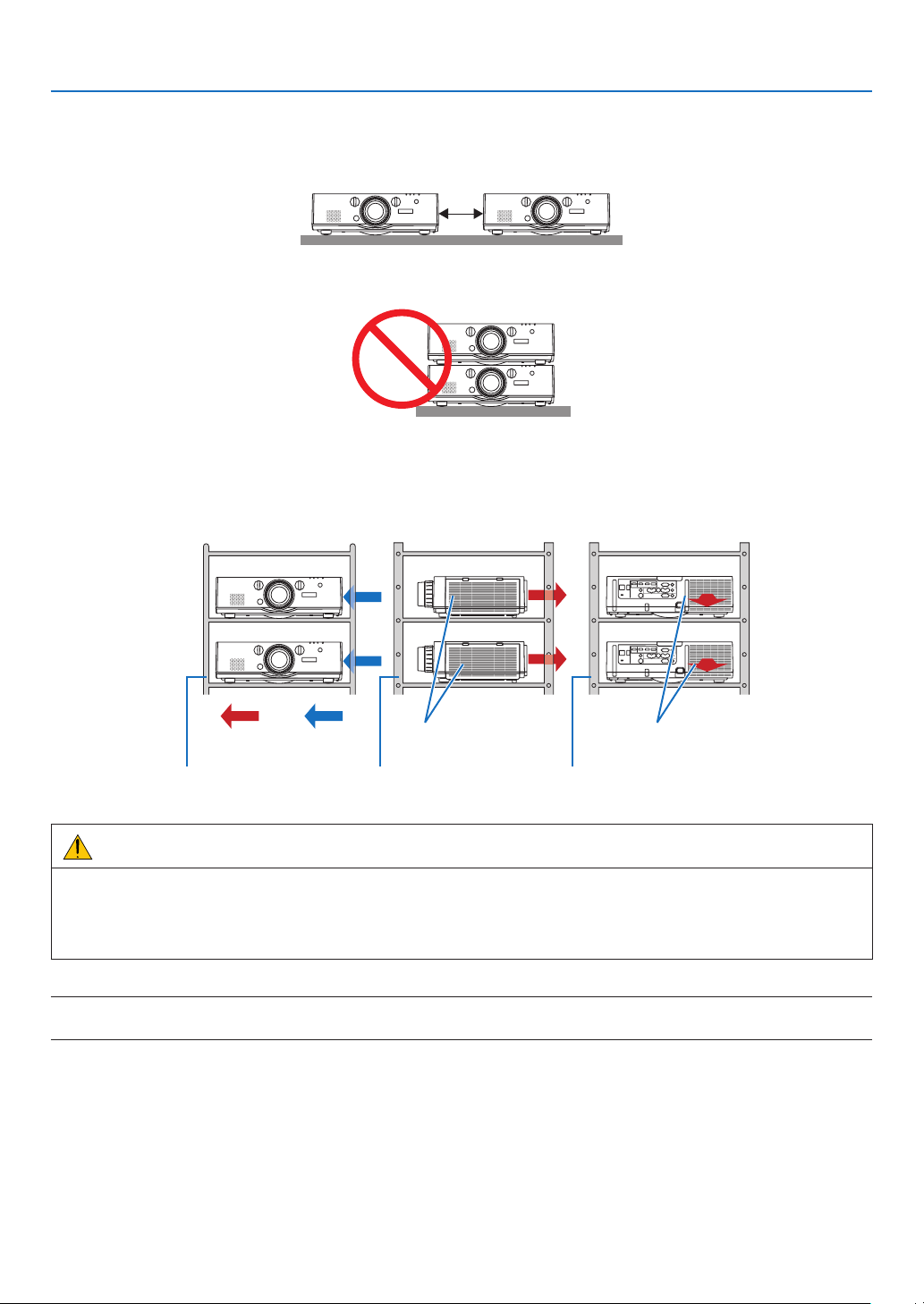
51
4. Multi-Screen Projection
Things to note when installing projectors
• Leavesufcientspaceontheleftandrightoftheprojectorsothattheairintakeanddischargeoutletsoftheprojector
arenotobstructed.Whentheairintakeanddischargeoutletareobstructed,thetemperatureinsidetheprojector
willriseandthismayresultinamalfunction.
• Pleasedonotpileuptheprojectorsdirectlyontopofoneanotherwheninstallingthem.Whentheprojectorsare
piledupontopofoneanother,theymayfalldown,resultingindamageandfailure.
• Installationexamplewhenusingtwoprojectors
Thefollowinginstallationisrecommendedwhencombiningtheinstallationoftwoprojectorsformulti-screenprojec-
tion.Pleaseleaveaspaceofatleast10cmbetweentheairintake/dischargeoutletandthewall.
[Installationexample]
Airintakeopening Airdischargeoutlet
CabinetCabinetCabinet
Airdis-
charge
Airintake
Front Rightside Back
WARNING
Pleaserequesttheretailstoreforspecialinstallationservicessuchaswhenmountingtheprojectortotheceiling.
Nevercarryouttheinstallationbyyourself.Theprojectormayfalldownandresultininjury.Pleaseuseasturdy
cabinetthatcanwithstandtheweightoftheprojectorfortheinstallation.Pleasedonotpileuptheprojectorsdirectly
ontopofoneanother.
NOTE:
• Fortherangeoftheprojectiondistance,pleaserefertotheAppendix“Throwdistanceandscreensize”.(→ page 158)
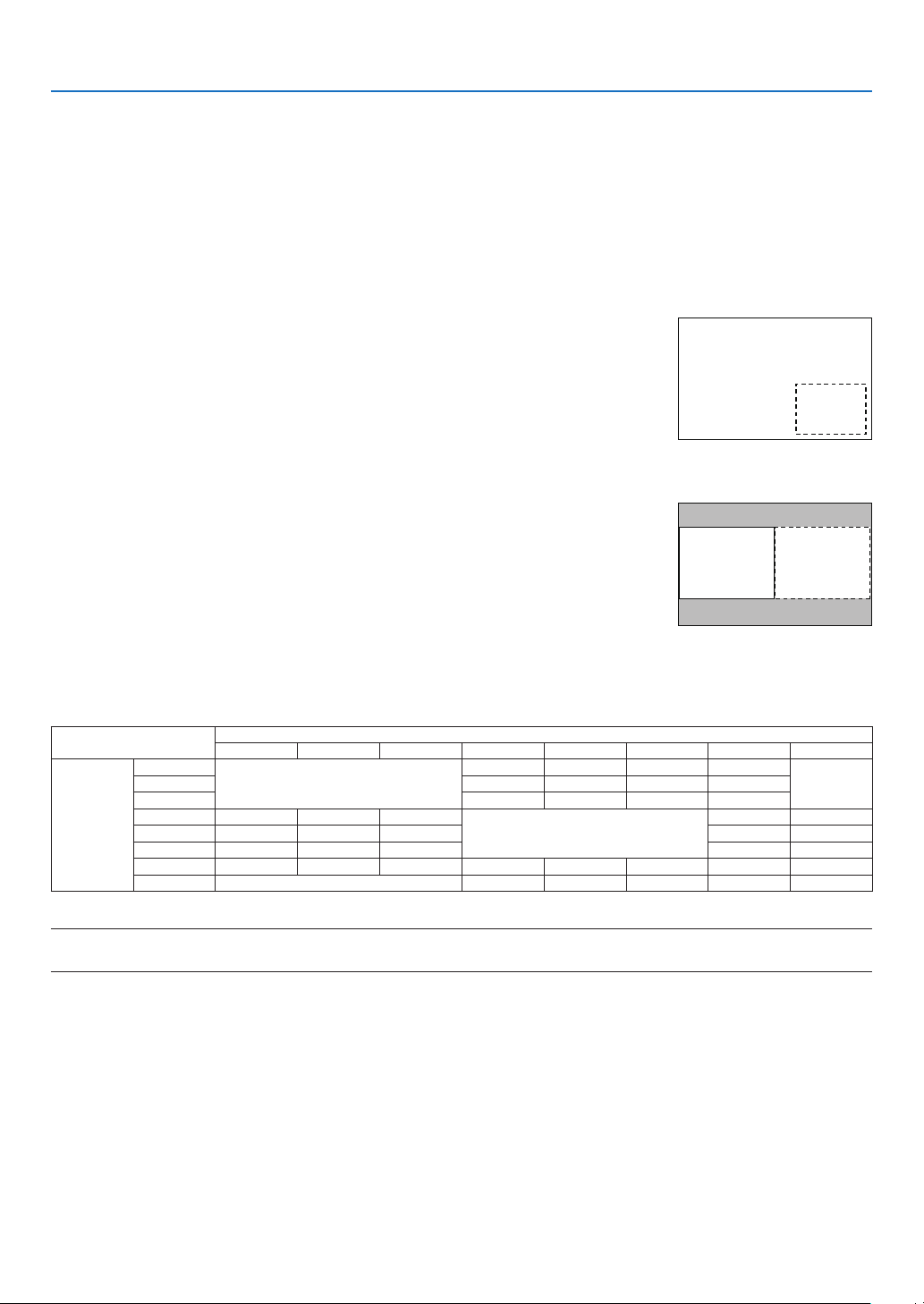
52
4. Multi-Screen Projection
❷ Displaying Two Pictures at the Same Time
Theprojectorhasafeaturethatallowsyoutoviewtwodifferentsignalssimultaneously.Youhavetwomodes:PIP
modeandPICTUREBYPICTUREmode.
Theprojectionvideointherstscreendisplayisknownasthemaindisplaywhiletheprojectionvideothatiscalled
outsubsequentlyisknownasthesub-display.
Selecttheprojectionfunctionunder[DISPLAY]→[PIP/PICTUREBYPICTURE]→[MODE]intheon-screenmenu
(thedefaultfactorysettingwhenshippedisPIP).(→page85)
• Asinglescreenisprojectedwhenpoweristurnedon.
Picture in Picture function
Asmallsub-displayisdisplayedinsidethemaindisplay.
Thesub-displaycanbesetupandadjustedasfollows.(→page86)
• Selectwhethertodisplaythesub-displayatthetopright,topleft,bottomright
orbottomleftofthescreen(thesizeofthesub-displaycanbeselectedand
thepositioncanbene-tuned)
• Switchthemaindisplaywiththesub-display
Main Display
Sub-
Display
Picturebypicturefunction
Displaythemaindisplayandsub-displaysidebyside.
Themaindisplayandsub-displaycanbesetupandadjustedasfollows.(→
page86)
• Selectingthedisplayboundary(ratio)ofthemaindisplayandsub-display
• Switchthemaindisplayandsub-display
Main Display Sub-Display
Input terminals that can be used for the main screen and sub-screen.
Themainscreenandsub-screencanprovidethefollowinginputterminals.
• Themaindisplayandsub-displaysupportcomputersignalsuptoWUXGA@60HzRB.
Sub-Display or additional display
HDMI1 HDMI2 DisplayPort BNC BNC(CV) BNC(Y/C) COMPUTER HDBaseT
Main Display
HDMI1
No
Yes Yes Yes Yes
NoHDMI2 Yes Yes Yes Yes
DisplayPort Yes Yes Yes Yes
BNC Yes Yes Yes
No
No Yes
BNC(CV) Yes Yes Yes Yes Yes
BNC(Y/C) Yes Yes Yes Yes Yes
COMPUTER Yes Yes Yes No Yes Yes No Yes
HDBaseT No Yes Yes Yes Yes No
NOTE:
• Somesignalsmaynotappeardependingontheresolution.
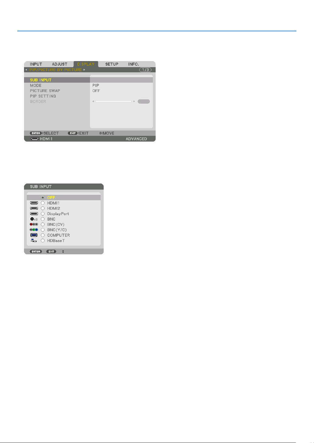
53
4. Multi-Screen Projection
Projecting two screens
1. PresstheMENU buttontodisplaytheon-screenmenuandselect[DISPLAY]→[PIP/PICTURE BYPIC-
TURE].
Thisdisplaysthe[PIP/PICTUREBYPICTURE]screenintheon-screenmenu.
2. Select[SUBINPUT]usingthe▼/▲ buttons, and press the ENTER button.
Thisdisplaysthe[SUBINPUT]screen.
3. Select the input signal using the ▼/▲ buttons, and press the ENTER button.
The[PIP](PICTUREINPICTURE)or[PICTUREBYPICTURE]screensetupunder[MODE]isprojected.(→page
85)
• Whenthesignalnameisdisplayedingrey,thismeansthatitcannotbeselected.
• ThesignalcanalsobeselectedbypressingthePIPbuttonorPBP/POPbuttonontheremotecontrol.
4. Press the MENU button.
Theon-screenmenuwilldisappear.
5. Whenreturningtosinglescreen,displaythe[PIP/PICTUREBYPICTUE]screenonemoretimeandselect
[OFF]inthe[SUBINPUT]screenoftheStep3.
TIP:
• Duringdual-screenprojection,iftheselectedinputisnotsupportedbythesub-screen,thesub-screenwillappearasablack
screen.
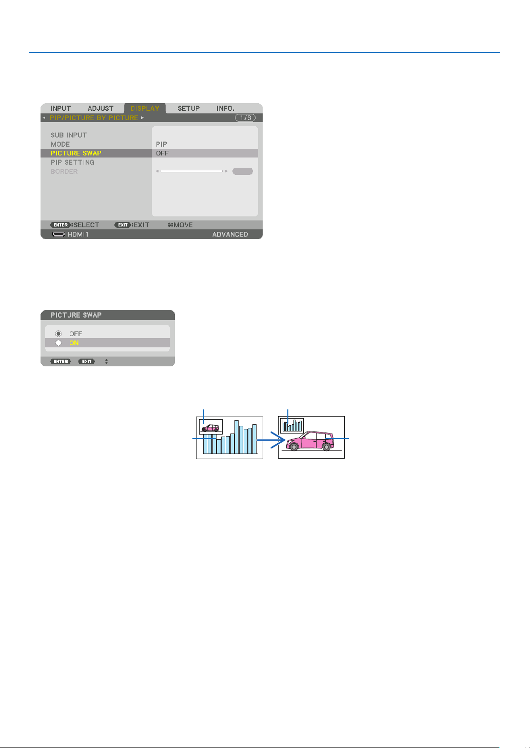
54
4. Multi-Screen Projection
Switching the main display with the sub-display and vice versa
1. PresstheMENU buttontodisplaytheon-screenmenuandselect[DISPLAY]→[PIP/PICTURE BYPIC-
TURE].
Thisdisplaysthe[PIP/PICTUREBYPICTURE]screenintheon-screenmenu.
2. Select[PICTURESWAP]usingthe▼/▲ buttons and then press the ENTER button.
Displaythescreenforswitchingthedisplaypositions.
3. Select[ON]usingthe▼ button and then press the ENTER button.
Thevideoofthemaindisplaywillswitchwiththatofthesub-display.
Whenturned“OFF” Whenturned“ON”
Sub-displayvideo
Maindisplayvideo Sub-displayvideo
Maindisplayvideo
ThesignaloutputfromtheHDMIoutputterminaldoesnotchangeevenifthedisplaypositionsareswitched.
4. Press the menu button.
Theon-screenmenuwilldisappear.

55
4. Multi-Screen Projection
Restrictions
• Thefollowingoperationsareenabledonlyforthemaindisplay.
• Audio-visualadjustments
• Videomagnication/compressionusingthepartialD-ZOOM/ZOOM+/−buttons.
However,magnication/compressionisuptothepositionssetin[PICTUREBYPICTUREBORDER]only.
• TESTPATTERN
• Thefollowingoperationsareenabledforboththemaindisplayandsub-display.Theseoperationscannotbeap-
pliedindividually.
• Momentarydeletionofvideo/audio
• Videopause
• [PIP/PICTUREBYPICTURE]cannotbeusedwhena3Dvideoisbeingdisplayed.
• Whenusingthe[PIP/PICTUREBYPICTURE]function,[CLOSEDCAPTION]and[DYNAMICCONTRAST]can
beused.
• [PIP/PICTUREBYPICTURE]cannotbeusedwhenthesignalinputhasaresolutionof1920×1200ormore.
• TheHDMIoutputterminalhasarepeaterfunction.Theoutputresolutionislimitedbythemaximumresolutionof
theconnectedmonitorandprojector.
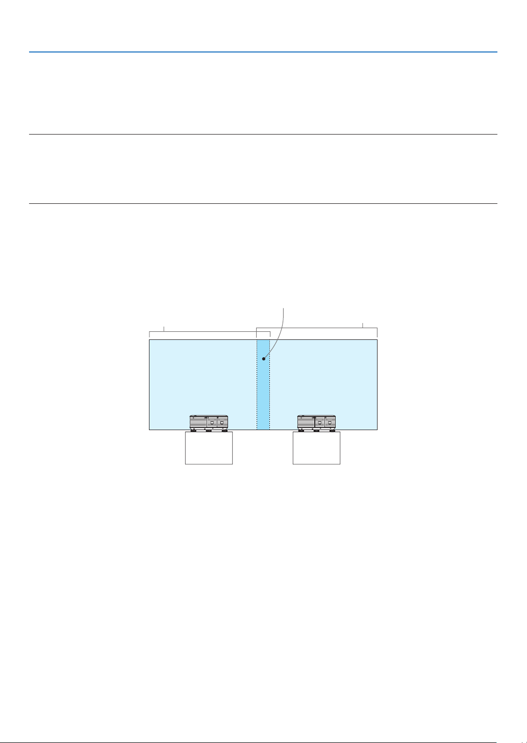
56
4. Multi-Screen Projection
❸ Displaying a Picture Using [EDGE BLENDING]
Ahighresolutionvideocanbeprojectedonanevenbiggerscreenbycombiningmultipleprojectorsontheleft,right,
topandbottom.
Thisprojectorisequippedwithan“EDGEBLENDINGFunction”thatmakestheedges(boundaries)oftheprojection
screenindistinguishable.
NOTE:
• Forprojectorthrowdistances,referto“Throwdistanceandscreensize”onpage158.
• BeforeperformingtheEdgeBlendingfunction,placetheprojectorinthecorrectpositionsothattheimagebecomessquarein
the appropriate size, and then make optical adjustments (lens shift, focus, and zoom).
• Adjustthebrightnessofeachprojectorusing[LAMPADJUST]under[LAMPMODE].Inaddition,use[REF.WHITEBALANCE]to
adjustthe[CONTRAST],[BRIGHTNESS]and[UNIFORMITY].
Before explaining use of the Edge Blending function
Thissectionexplainsthecasefor“Example:Placingtwoprojectorssidebyside”.Asshown,theprojectedimageon
theleftisreferredtoas“ProjectorA”andtheprojectedimageontherightisreferredto“ProjectorB”.Unlessotherwise
speciedhereinafter,the“projector”isusedtomeanbothAandB.
Example:Placingtwoprojectorssidebyside
EdgeBlendingarea
Projectedarea
Projectedarea
ProjectorA ProjectorB
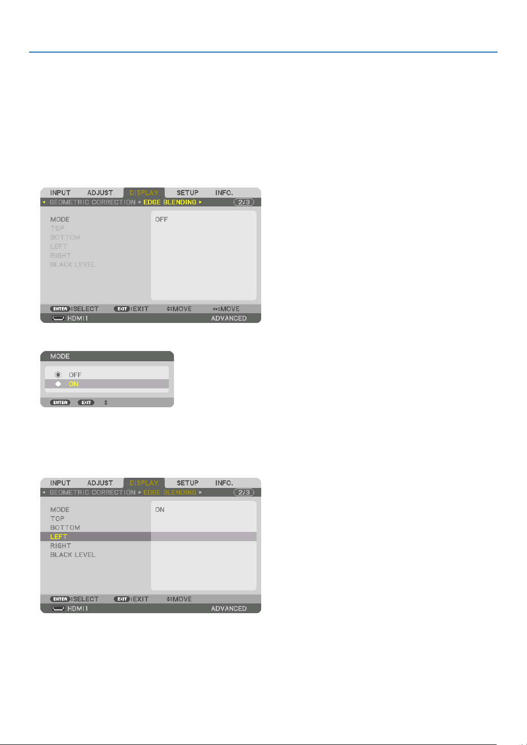
57
4. Multi-Screen Projection
Preparation:
• Turnontheprojectoranddisplayasignal.
• Whenperformingsettingsoradjustmentsusingtheremotecontrol,enablethe[CONTROLID]soasnottoactivate
theotherprojectors.(→page105)
Setting the overlap of projection screens
① Enable [EDGE BLENDING].
1 Press the “Edge Blend.” button.
The[EDGEBLENDING]screenwillbedisplayed.Alignthecursorwith[MODE]andthenpresstheENTERbutton.
Themodescreenwillbedisplayed.
2 Select[MODE]→[ON]andpresstheENTERbutton.
ThisenablestheEdgeBlendingfunction.Thefollowingmenuitemsareavailable:
[TOP],[BOTTOM],[LEFT],[RIGHT],and[BLACKLEVEL]
3 Select[RIGHT]forProjectorAand[LEFT]forProjectorB.
PresstheENTERbutton.
Thefollowingitemsareavailable:
[CONTROL],[MARKER],[RANGE],and[POSITION]
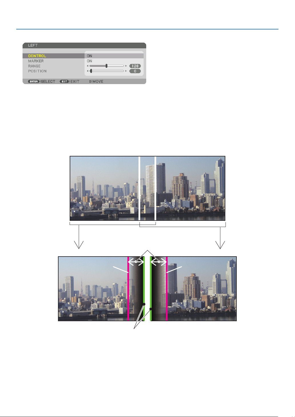
58
4. Multi-Screen Projection
4 Select[CONTROL]→[ON]andpresstheENTERbutton.
Each[TOP],[BOTTOM],[LEFT],[RIGHT],and[BLACKLEVEL]hasitsown[CONTROL],[MARKER],[RANGE],
and[POSITION].
• ForProjectorA,setthe[CONTROL]forthe[TOP],[LEFT]and[BOTTOM]to[OFF].SimilarlyforProjectorB,set
the[CONTROL]forthe[TOP],[RIGHT]and[BOTTOM]to[OFF].
② Adjust [RANGE] and [POSITION] to determine an area of overlapped edges of images projected
from each projector.
Turningon[MARKER]willdisplaymarkersinmagentaandgreen.
Themagentamarkerisusedfor[RANGE]andgreenonefor[POSITION].
[RANGE]
(Determineanareaofoverlappededgesof
images.)
[POSITION]
(Determinethepositionofoverlappededgesofimages.)
Greenmarker
Turnon[RIGHT]
Magentamarker
Turnon[LEFT]
Magentamarker
* The2screensareseparatedinthediagramforexplanatorypurposes.
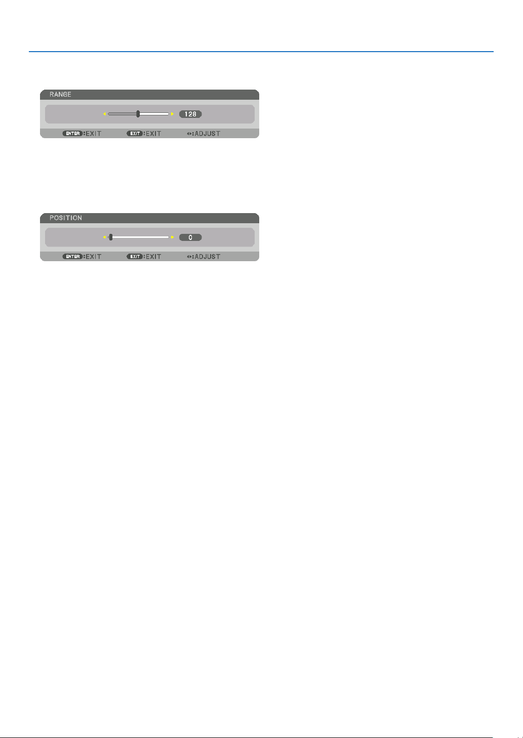
59
4. Multi-Screen Projection
1 Adjust[RANGE].
Usethe◀ or ▶buttontoadjusttheoverlappedarea.
TIP:
• Adjusttooverlaponeprojector’markerwiththeotherprojector’smarker.
2 Adjust[POSITION].
Usethe◀ or ▶buttontoalignoneedgewiththeotheredgeofoverlappedimages.
TIP:
• Whendisplayingasignalwithadifferentresolution,performtheEdgeBlendingfunctionfromthestart.
• Settingof[MARKER]willnotbesavedandreturnto[OFF]whentheprojectoristurnedoff.
• Todisplayorhidethemarkerwhiletheprojectorisrunning,turnonoroff[MARKER]fromthemenu.
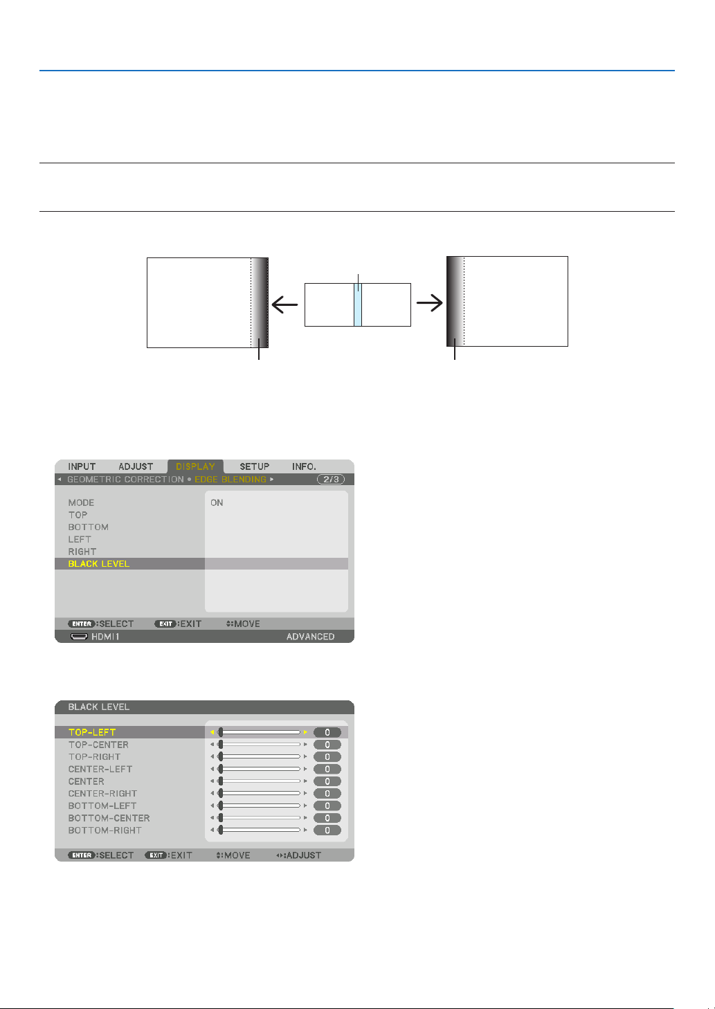
60
4. Multi-Screen Projection
Black Level Adjustment
Thisadjuststheblackleveloftheoverlappingareaandthenon-overlappingareaofthemulti-screen(EDGEBLEND-
ING).
Adjustthebrightnesslevelifyoufeelthedifferenceistoolarge.
NOTE:
Thisfunctionisenabledonlywhen[MODE]isturnedon.
Adjustableareavariesdependingonwhatcombinationof[TOP],[BOTTOM],[LEFT]and[RIGHT]areturnedon.
Example:AdjustingtheBlackLevelwhenplacingtwoprojectorssidebyside
Widthofoverlap
Adjust[CENTER] Adjust[CENTER]
ProjectorA’s
image
ProjectorB’s
image
Adjust[CENTER-RIGHT] Adjust[CENTER-LEFT]
1. Turnon[MODE]
2. Select[BLACKLEVEL]andpresstheENTERbutton.
Thescreenwillswitchtotheblackleveladjustmentscreen.
3. Use the ▼ or ▲ button to select an item and use the ◀ or ▶ to adjust the black level.
Dothisfortheotherprojectorifnecessary.
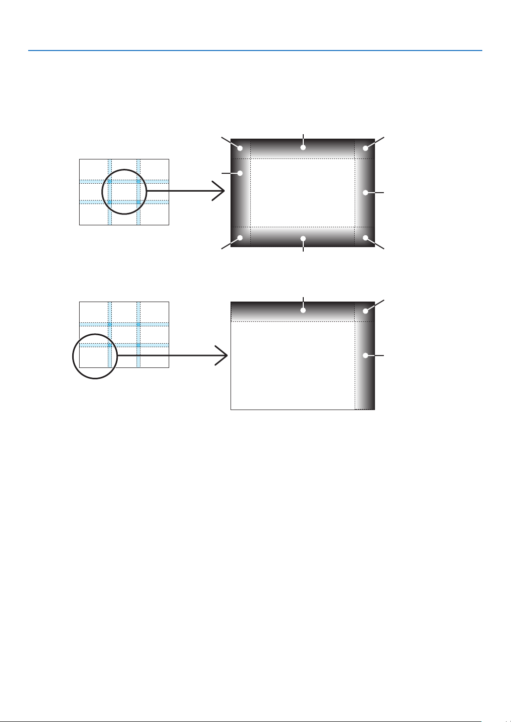
61
4. Multi-Screen Projection
9-segmentedportionsforBlackLeveladjustment
Thecenterprojector
Thisfunctionadjuststhebrightnesslevelof9-segmentedportionsforthecenterprojectorand4-segmentedportions
fortheleftbottomprojectorasshownbelow.
TOP-LEFT
BOTTOM-LEFT
CENTER-
LEFT
TOP-RIGHT
CENTER-RIGHT
BOTTOM-RIGHT
TOP-CENTER
CENTER
CENTER
BOTTOM-CENTER
TOP-RIGHT
CENTER-RIGHT
TOP-CENTER
TIP:
• Thenumberofblackleveldivisionscreens(maximumofninedivisions)changesdependingonthenumberofedgeblending
positions selected (top, bottom, right, left). In addition, when the top / bottom and left / right ends are selected, the corner division
screen appears.
• Theedgeblendingwidthisthewidthsetintherangeandthecornerisformedbytheintersectingareaofthetop/bottomends
or left / right ends.
• The[BLACKLEVEL]canbeadjustedtomakeitbrighteronly.
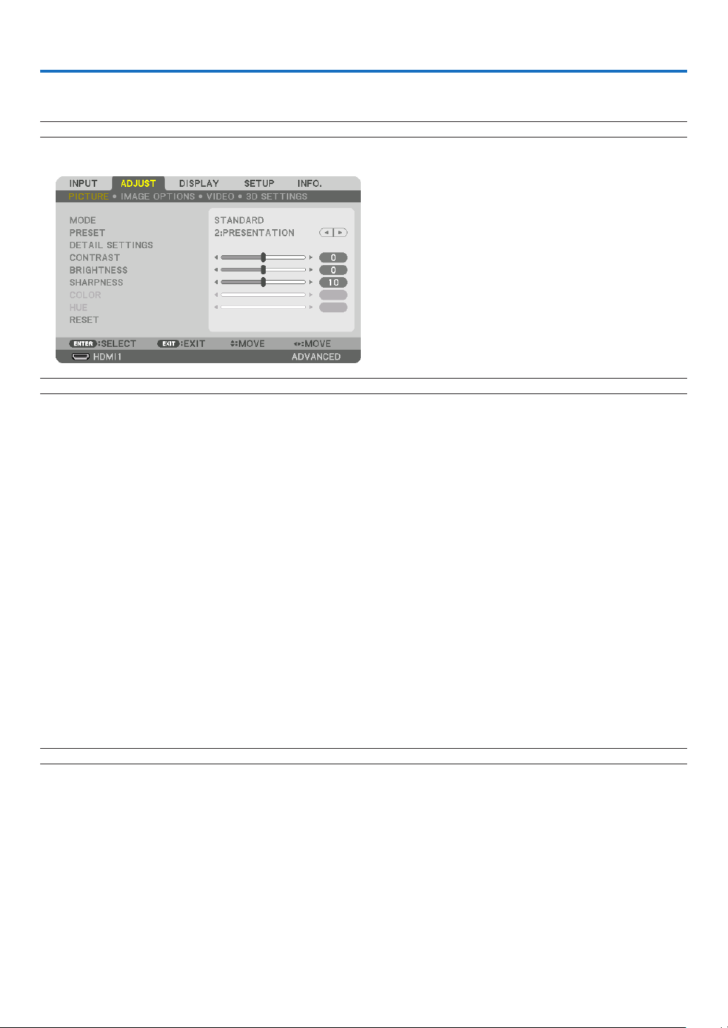
62
5. Using On-Screen Menu
❶ Using the Menus
NOTE: The on-screen menu may not be displayed correctly while interlaced motion video image is projected.
1. Press the MENU button on the remote control or the projector cabinet to display the menu.
NOTE: The commands such as ENTER,EXIT,▲▼, ◀▶ in the bottom show available buttons for your operation.
2. Press the ◀▶ buttons on the remote control or the projector cabinet to display the submenu.
3. Press the ENTER button on the remote control or the projector cabinet to highlight the top item or the first
tab.
4. Use the ▲▼ buttons on the remote control or the projector cabinet to select the item you want to adjust or
set.
You can use the ◀▶ buttons on the remote control or the projector cabinet to select the tab you want.
5. Press the ENTER button on the remote control or the projector cabinet to display the submenu window.
6. Adjust the level or turn the selected item on or off by using the ▲▼◀▶ buttons on the remote control or
the projector cabinet.
Changesarestoreduntiladjustedagain.
7. Repeat steps 2-6 to adjust an additional item, or press the EXIT button on the remote control or the projec-
tor cabinet to quit the menu display.
NOTE:Whenamenuormessageisdisplayed,severallinesofinformationmaybelost,dependingonthesignalorsettings.
8. Press the MENU button to close the menu.
To return to the previous menu, press the EXIT button.
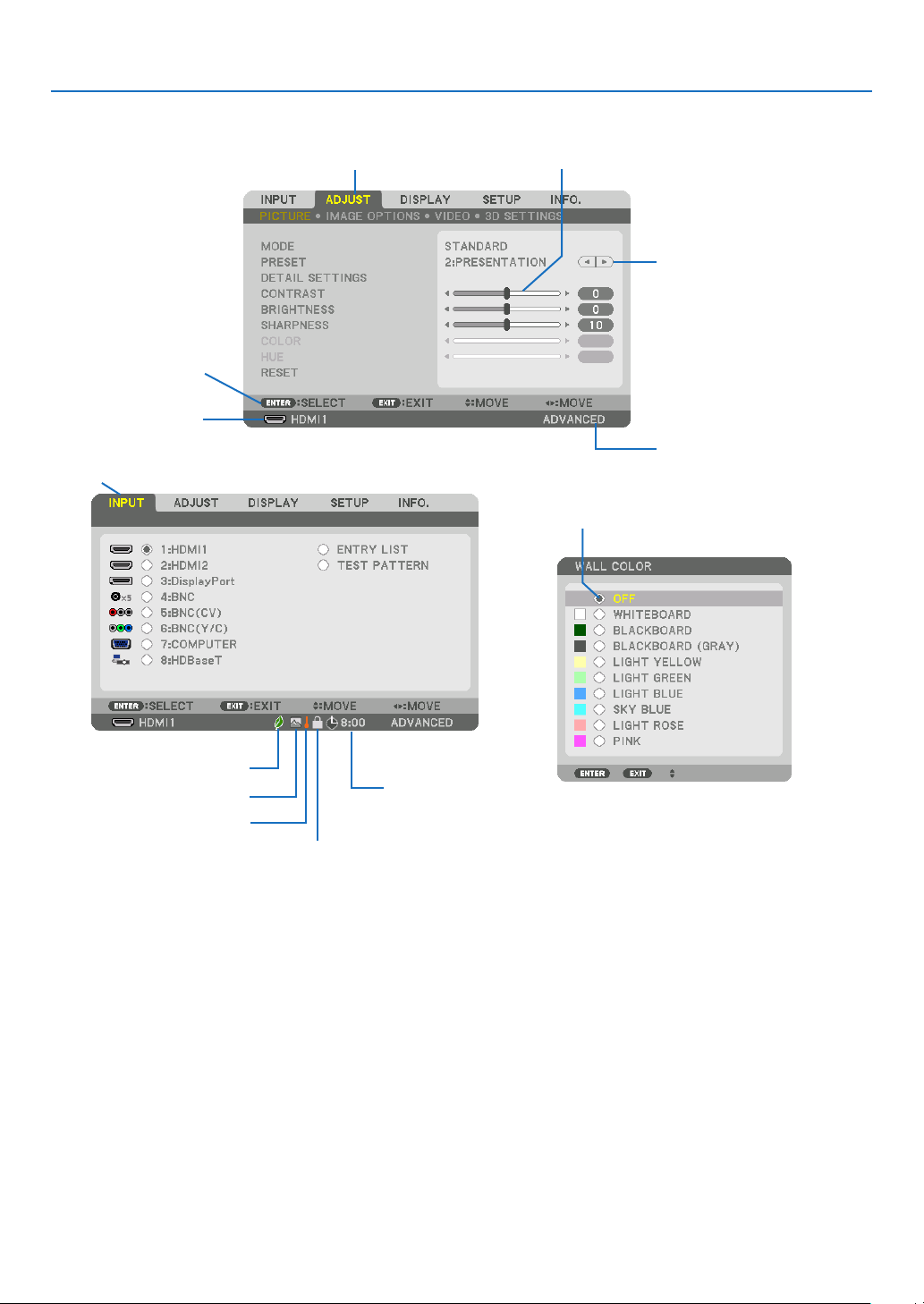
63
5. Using On-Screen Menu
❷
Menu Elements
Slidebar
Solidtriangle
Menumode
Tab
Radiobutton
HighAltitudesymbol
ECOmodesymbol
Menuwindowsordialogboxestypicallyhavethefollowingelements:
Highlight �����������������������������Indicates the selected menu or item�
Solid triangle ����������������������Indicates further choices are available� A highlighted triangle indicates the item is active�
Tab ��������������������������������������Indicates a group of features in a dialog box� Selecting on any tab brings its page to the front�
Radio button �����������������������Use this round button to select an option in a dialog box�
Source ��������������������������������Indicates the currently selected source�
Menu mode ������������������������Indicates the current menu mode: BASIC or ADVANCED�
Off Timer remaining time ����Indicates the remaining countdown time when the [OFF TIMER] is preset�
Slide bar �����������������������������Indicates settings or the direction of adjustment�
ECO mode symbol ��������������Indicates [ECO MODE] is set�
Key Lock symbol ����������������Indicates the [CONTROL PANEL LOCK] is enabled�
Thermometer symbol ���������Indicates the [ECO MODE] is forcibly set to [ON] mode because the internal temperature is too
high�
High Altitude symbol ����������Indicates the [FAN MODE] is set to [HIGH ALTITUDE] mode�
Source
Availablebuttons
Thermometersymbol
KeyLocksymbol
OffTimerremaining
time
Highlight
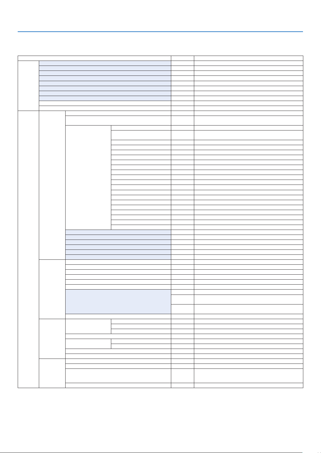
64
5. Using On-Screen Menu
* Theasterisk(*)indicatesthatthedefaultsettingvariesdependingonthesignal.
*1 The[GAMMACORRECTION]itemisavailablewhenanitemotherthan[DICOMSIM.]isselectedfor[REFERENCE].
*2 The[SCREENSIZE]itemisavailablewhen[DICOMSIM.]isselectedfor[REFERENCE].
*3 When[PRESENTATION]or[HIGH-BRIGHT]isselectedin[REFERENCE],the[COLORTEMPERATURE]isnotavailable.
•Basicmenuitemsareindicatedbyshadedarea.
❸ List of Menu Items
Somemenuitemsarenotavailabledependingontheinputsource.
Menu Item Default Options
INPUT
1:HDMI1 *
2:HDMI2 *
3:DisplayPort *
4:BNC *
5:BNC(CV) *
6:BNC(Y/C) *
7:COMPUTER *
8:HDBaseT
ENTRY LIST
TEST PATTERN
ADJUST
PICTURE
MODE STANDARD STANDARD, PROFESSIONAL
PRESET *
HIGH-BRIGHT, PRESENTATION, VIDEO, MOVIE, GRAPHIC, sRGB,
DICOM SIM�
DETAIL SETTINGS
GENERAL
REFERENCE *
HIGH-BRIGHT, PRESENTATION, VIDEO, MOVIE, GRAPHIC, sRGB,
DICOM SIM�
GAMMA CORRECTION*
1
DYNAMIC, NATURAL, BLACK DETAIL
SCREEN SIZE*
2
* LARGE, MEDIUM, SMALL
COLOR TEMPERATURE*
3
*
DYNAMIC CONTRAST * OFF, MOTION IMAGE, STILL IMAGE
WHITE BALANCE
CONTRAST R 0
CONTRAST G 0
CONTRAST B 0
BRIGHTNESS R 0
BRIGHTNESS G 0
BRIGHTNESS B 0
COLOR CORRECTION
RED 0
GREEN 0
BLUE 0
YELLOW 0
MAGENTA 0
CYAN 0
CONTRAST 50
BRIGHTNESS 50
SHARPNESS 10
COLOR 50
HUE 0
RESET
IMAGE
OPTIONS
CLOCK *
PHASE *
HORIZONTAL *
VERTICAL *
BLANKING * TOP, BOTTOM, LEFT, RIGHT
OVERSCAN * AUTO, 0[%], 5[%], 10[%]
ASPECT RATIO
* (COMPUTER) AUTO, 4:3, 5:4, 16:9, 15:9, 16:10, NATIVE
*
(COMPONENT/VIDEO/S-VIDEO) AUTO, 4:3, LETTERBOX, WIDE
SCREEN, ZOOM
*
(COMPONENT/VIDEO/S-VIDEO) AUTO, 4:3 WINDOW, LETTERBOX,
WIDE SCREEN, FULL
INPUT RESOLUTION * –
VIDEO
NOISE REDUCTION
RANDOM NR * OFF, LOW, MEDIUM, HIGH
MOSQUITO NR OFF OFF, LOW, MEDIUM, HIGH
BLOCK NR OFF OFF, LOW
DEINTERLACE NORMAL NORMAL, MOVIE, STILL
CONTRAST
ENHANCEMENT
MODE AUTO OFF, AUTO, NORMAL
GAIN
SIGNAL TYPE AUTO AUTO, RGB, COMPONENT
VIDEO LEVEL AUTO AUTO, NORMAL, ENHANCED
3D SETTINGS
STEREO VIEWER SINGLE SINGLE, DUAL LEFT, DUAL RIGHT
STEREO FILTER SINGLE SINGLE, DUAL LEFT, DUAL RIGHT
FORMAT AUTO
AUTO, OFF(2D), FRAME PACKING, SIDE BY SIDE(HALF), SIDE
BY SIDE(FULL), TOP AND BOTTOM, FRAME ALTERNATIVE, LINE
ALTERNATIVE
L/R INVERT OFF OFF, ON
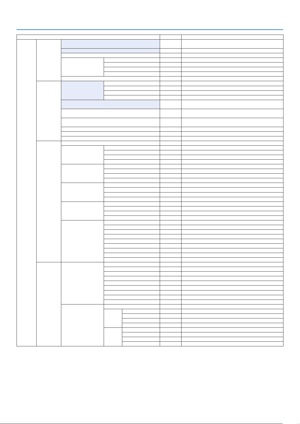
65
5. Using On-Screen Menu
Menu Item Default Options
DISPLAY
PIP/PICTURE
BY PICTURE
SUB INPUT
OFF, HDMI1, HDMI2, DisplayPort, BNC, BNC(CV), BNC(Y/C),
COMPUTER, HDBaseT
MODE PIP, PICTURE BY PICTURE
PICTURE SWAP OFF OFF, ON
PIP SETTING
START POSITION TOP-LEFT, TOP-RIGHT, BOTTOM-LEFT, BOTTOM-RIGHT
HORIZONTAL POSITION
VERTICAL POSITION
SIZE LARGE, MEDIUM, SMALL
BORDER
GEOMETRIC
CORRECTION
KEYSTONE
HORIZONTAL
VERTICAL
TILT
THROW RATIO
CORNERSTONE
TOP-LEFT, TOP, TOP-RIGHT, LEFT, RIGHT, BOTTOM-LEFT,
BOTTOM, BOTTOM-RIGHT
HORIZONTAL CORNER
TOP-LEFT, TOP, TOP-RIGHT, LEFT, RIGHT, BOTTOM-LEFT,
BOTTOM, BOTTOM-RIGHT
VERTICAL CORNER
TOP-LEFT, TOP, TOP-RIGHT, LEFT, RIGHT, BOTTOM-LEFT,
BOTTOM, BOTTOM-RIGHT
PINCUSHION TOP, BOTTOM, LEFT, RIGHT
PC TOOL OFF OFF, 1, 2, 3
RESET
EDGE
BLENDING
MODE OFF OFF, ON
TOP
CONTROL ON OFF, ON
MARKER ON OFF, ON
RANGE
POSITION
BOTTOM
CONTROL ON OFF, ON
MARKER ON OFF, ON
RANGE
POSITION
LEFT
CONTROL ON OFF, ON
MARKER ON OFF, ON
RANGE
POSITION
RIGHT
CONTROL ON OFF, ON
MARKER ON OFF, ON
RANGE
POSITION
BLACK LEVEL
TOP-LEFT
TOP-CENTER
TOP-RIGHT
CENTER-LEFT
CENTER
CENTER-RIGHT
BOTTOM-LEFT
BOTTOM-CENTER
BOTTOM-RIGHT
MULTI
SCREEN
WHITE BALANCE
MODE OFF OFF, ON
CONTRAST W
CONTRAST R
CONTRAST G
CONTRAST B
BRIGHTNESS W
BRIGHTNESS R
BRIGHTNESS G
BRIGHTNESS B
PICTURE SETTING
MODE OFF OFF, ZOOM, TILING
ZOOM
HORIZONTAL ZOOM
VERTICAL ZOOM
HORIZONTAL POSITION
VERTICAL POSITION
TILING
WIDTH 1 UNIT, 2 UNITS, 3 UNITS, 4 UNITS
HEIGHT 1 UNIT, 2 UNITS, 3 UNITS, 4 UNITS
HORIZONTAL POSITION 1st UNIT, 2nd UNIT, 3rd UNIT, 4th UNIT
VERTICAL POSITION 1st UNIT, 2nd UNIT, 3rd UNIT, 4th UNIT
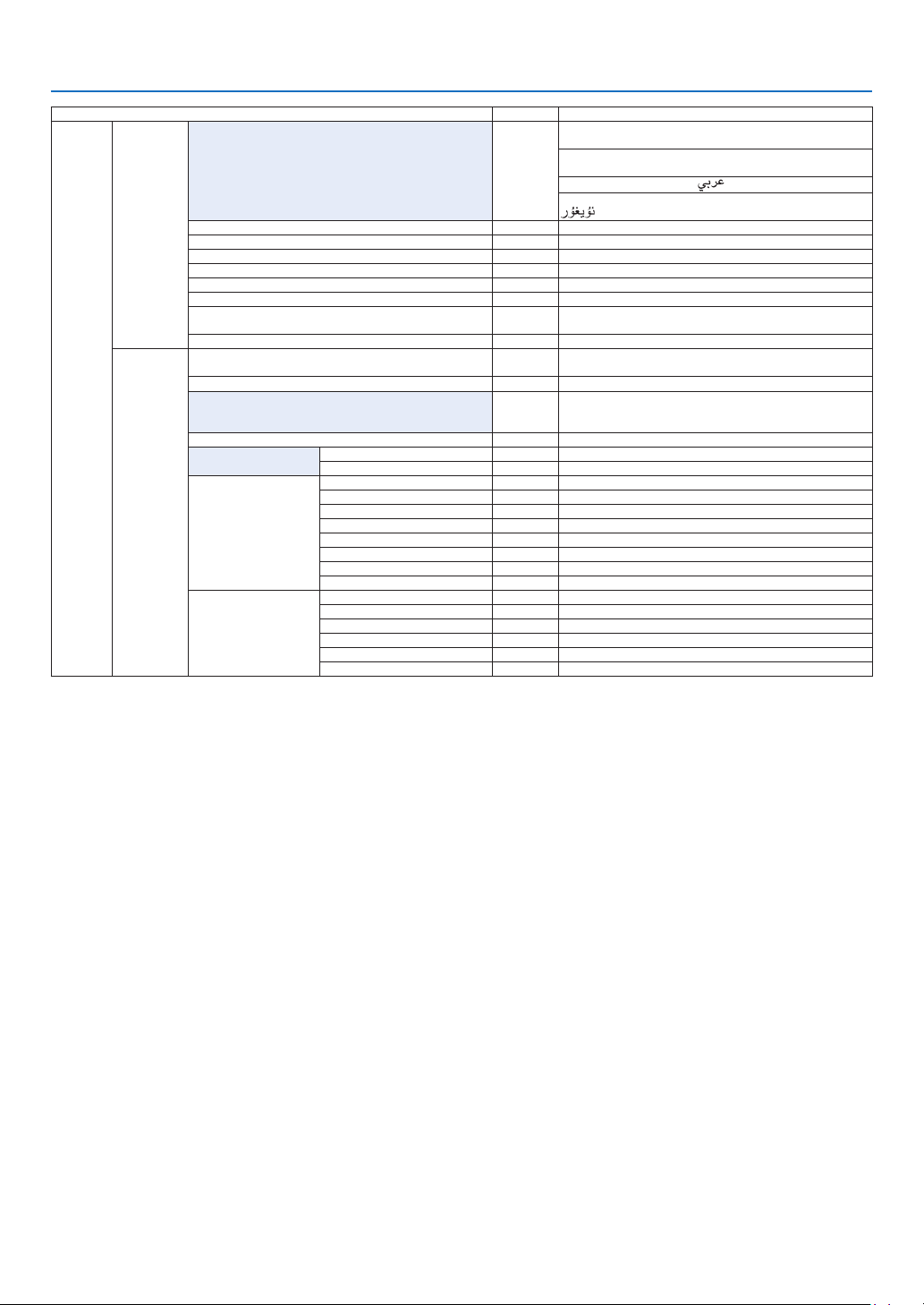
66
5. Using On-Screen Menu
Menu Item Default Options
SETUP
MENU
LANGUAGE ENGLISH
ENGLISH, DEUTSCH, FRANÇAIS, ITALIANO, ESPAÑOL, SVENSKA,
日本語
DANSK, PORTUGUÊS, ČEŠTINA, MAGYAR, POLSKI,
NEDERLANDS, SUOMI
NORSK, TÜRKÇE, РУССКИЙ,
, Ελληνικά, 中文, 한국어
ROMÂNĂ, HRVATSKA, БЪЛГАРСКИ, INDONESIA, , ไทย,
, 繁體中文
COLOR SELECT COLOR COLOR, MONOCHROME
INPUT DISPLAY ON OFF, ON
MESSAGE DISPLAY ON OFF, ON
ID DISPLAY ON OFF, ON
ECO MESSAGE OFF OFF, ON
3D CAUTION MESSAGE ON OFF, ON
DISPLAY TIME
AUTO 45
SEC
MANUAL, AUTO 5 SEC, AUTO 15 SEC, AUTO 45 SEC
FILTER MESSAGE OFF OFF, 100[H], 500[H], 1000[H], 2000[H]
INSTALLATION
ORIENTATION AUTO
AUTO, DESKTOP FRONT, CEILING REAR, DESKTOP REAR,
CEILING FRONT
SCREEN TYPE FREE FREE, 4:3 SCREEN, 16:9 SCREEN, 16:10 SCREEN
WALL COLOR OFF
OFF, WHITEBOARD, BLACKBOARD, BLACKBOARD (GRAY), LIGHT
YELLOW, LIGHT GREEN, LIGHT BLUE, SKY BLUE, LIGHT ROSE,
PINK
FAN MODE AUTO AUTO, HIGH, HIGH ALTITUDE
LAMP MODE
ECO MODE OFF OFF, ON
LAMP ADJUST
REF� WHITE BALANCE
CONTRAST R
CONTRAST G
CONTRAST B
BRIGHTNESS R
BRIGHTNESS G
BRIGHTNESS B
UNIFORMITY R
UNIFORMITY B
STATIC CONVERGENCE
HORIZONTAL R
HORIZONTAL G
HORIZONTAL B
VERTICAL R
VERTICAL G
VERTICAL B
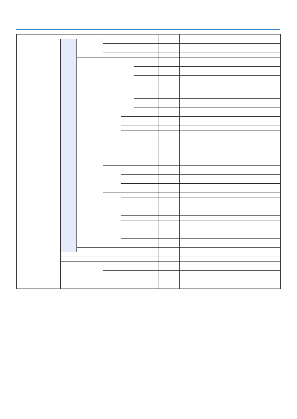
67
5. Using On-Screen Menu
Menu Item Default Options
SETUP CONTROL
TOOLS
ADMINISTRA-
TOR MODE
MENU MODE ADVANCED ADVANCED, BASIC
NOT SAVE SETTING VALUES OFF OFF, ON
NEW PASSWORD
CONFIRM PASSWORD
PROGRAM
TIMER
ENABLE OFF OFF, ON
SETTINGS
EDIT
ACTIVE OFF, ON
DAY
SUN, MON, TUE, WED, THU, FRI, SAT, MON-FRI, MON-SAT, EVERY
DAY
TIME
FUNCTION POWER, INPUT, ECO MODE
ADVANCED
SETTINGS
POWER OFF, ON
INPUT
HDMI1, HDMI2, DisplayPort, BNC, BNC(CV), BNC(Y/C),
COMPUTER, HDBaseT
ECO MODE OFF, ON
REPEAT OFF, ON
DELETE
UP
DOWN
BACK
DATE AND TIME
SETTINGS
TIME
ZONE
SETTIMGS
GMT
-12:00, -11:30, -11:00, -10:30, -10:00, -09:30, -09:00, -08:30,
-08:00, -07:30, -07:00, -06:30, -06:00, -05:30, -05:00, -04:30,
-04:00, -03:30, -03:00, -02:30, -02:00, -01:30, -01:00, -00:30,
00:00, +00:30, +01:00, +01:30, +02:00, +02:30, +03:00, +03:30,
+04:00, +04;30, +05:00, +05:30, +06:00, +06:30, +07:00, +07:30,
+08:00, +08:30, +09:00, +09:30, +10:00, +10:30, +11:00, +11:30,
+12:00, +12:30, +13:00
DATE
AND TIME
SETTINGS
DATE MM/DD/YYYY
TIME HH:MM
INTERNET TIME
SERVER
OFF, ON
IP ADDRESS
UPDATE
SUMMER
TIME
SETTINGS
ENABLE OFF, ON
MON(START) 1, 2, 3, 4, 5, 6, 7, 8, 9, 10, 11, 12
DAY(START)
FIRST WEEK, SECOND WEEK, THIRD WEEK, FOURTH WEEK, LAST
WEEK
SUN, MON, TUE, WED, THU, FRI, SAT
TIME(START)
MON(EXIT) 1, 2, 3, 4, 5, 6, 7, 8, 9, 10, 11, 12
DAY(EXIT)
FIRST WEEK, SECOND WEEK, THIRD WEEK, FOURTH WEEK, LAST
WEEK
SUN, MON, TUE, WED, THU, FRI, SAT
TIME(EXIT)
TIME DIFFERENCE +01:00, +00:30, -00:30, -01:00
MOUSE
(Note) Cannot be used for this device�
CONTROL PANEL LOCK OFF OFF, ON
SECURITY OFF OFF, ON
COMMUNICATION SPEED 38400bps 4800bps, 9600bps, 19200bps, 38400bps, 115200bps
CONTROL ID
CONTROL ID NUMBER 1 1–254
CONTROL ID OFF OFF, ON
REMOTE SENSOR
FRONT/
BACK
FRONT/BACK, FRONT, BACK, HDBase-T
BEEP ON OFF, ON
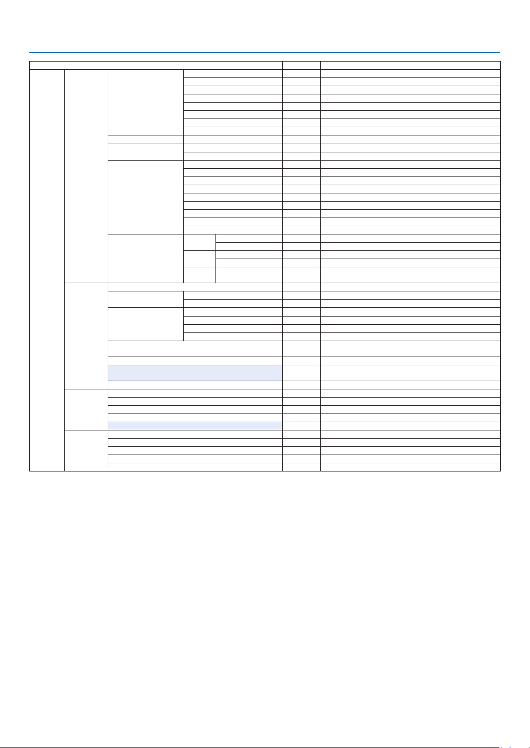
68
5. Using On-Screen Menu
Menu Item Default Options
SETUP
NETWORK
SETTINGS
WIRED LAN
PROFILES DISABLE, PROFILE 1, PROFILE 2
DHCP OFF, ON
IP ADDRESS
192�168�0�10
SUBNET MASK 255�255�255�0
GATEWAY 192�168�0�1
AUTO DNS OFF, ON
DNS CONFIGURATION
RECONNECT
PROJECTOR NAME PROJECTOR NAME PA622U Series
DOMAIN
HOST NAME necpj
DOMAIN NAME
ALERT MAIL
ALERT MAIL OFF, ON
HOST NAME
DOMAIN NAME
SENDER'S ADDRESS
SMTP SERVER NAME
RECIPIENT'S ADDRESS 1
RECIPIENT'S ADDRESS 2
RECIPIENT'S ADDRESS 3
TEST MAIL
NETWORK SERVICE
HTTP
SERVER
NEW PASSWORD
CONFIRM PASSWORD
PJLink
NEW PASSWORD
CONFIRM PASSWORD
AMX
BEACON
OFF, ON
SOURCE
OPTIONS
AUTO ADJUST NORMAL OFF, NORMAL, FINE
COLOR SYSTEM
BNC(VIDEO) AUTO
AUTO, NTSC3�58, NTSC4�43, PAL, PAL-M, PAL-N, PAL60, SECAM
BNC(Y/C) AUTO AUTO, NTSC3�58, NTSC4�43, PAL, PAL-M, PAL-N, PAL60, SECAM
AUDIO SELECT
HDMI1 HDMI1 HDMI1, BNC
HDMI2 HDMI2 HDMI2, BNC
DisplayPort DisplayPort DisplayPort, BNC
HDBaseT HDBaseT HDBaseT, BNC
DEFAULT INPUT SELECT LAST
LAST, AUTO, HDMI1, HDMI2, DisplayPort, BNC, BNC(CV),
BNC(Y/C), COMPUTER, HDBaseT
SEAMLESS SWITCHING OFF OFF, ON
CLOSED CAPTION OFF
OFF, CAPTION1, CAPTION2, CAPTION3, CAPTION4, TEXT1, TEXT2,
TEXT3, TEXT4
BACKGROUND BLUE BLUE, BLACK, LOGO
POWER
OPTIONS
STANDBY MODE NORMAL NORMAL, HDBaseT STANDBY
DIRECT POWER ON OFF OFF, ON
AUTO POWER ON SELECT OFF OFF, HDMI1, HDMI2, DisplayPort, COMPUTER, HDBaseT
AUTO POWER OFF 1:00 OFF, 0:05, 0:10, 0:15, 0:20, 0:30, 1:00
OFF TIMER OFF OFF, 0:30, 1:00, 2:00, 4:00, 8:00, 12:00, 16:00
RESET
CURRENT SIGNAL
ALL DATA
ALL DATA (INCLUDING ENTRY LIST)
CLEAR LAMP HOURS
CLEAR FILTER HOURS
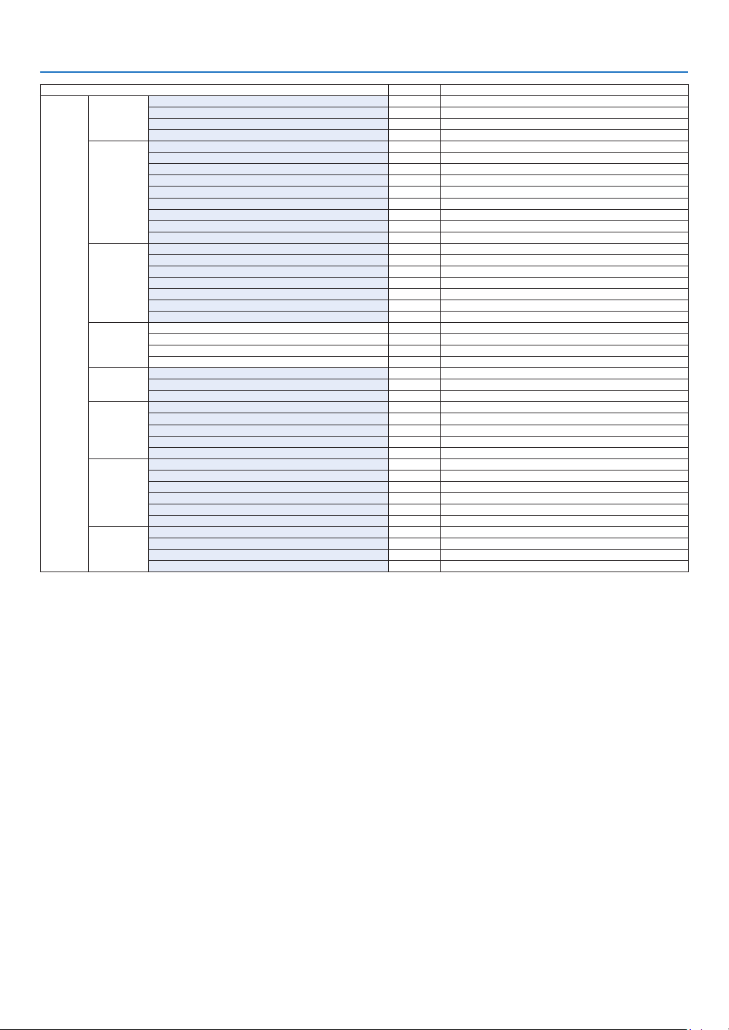
69
5. Using On-Screen Menu
Menu Item Default Options
INFO�
USAGE TIME
LAMP LIFE REMAINING
LAMP HOURS USED
FILTER HOURS USED
TOTAL CARBON SAVINGS
SOURCE(1)
INPUT TERMINAL
RESOLUTION
HORIZONTAL FREQUENCY
VERTICAL FREQUENCY
SYNC TYPE
SYNC POLARITY
SCAN TYPE
SOURCE NAME
ENTRY NO�
SOURCE(2)
SIGNAL TYPE
VIDEO TYPE
BIT DEPTH
VIDEO LEVEL
LINK RATE
LINK LANE
3D FORMAT
WIRED LAN
IP ADDRESS
SUBNET MASK
GATEWAY
MAC ADDRESS
VERSION(1)
FIRMWARE
DATA
SUB-CPU
OTHERS
DATE TIME
PROJECTOR NAME
MODEL NO�
SERIAL NUMBER
CONTROL ID (when [CONTROL ID] is set)
CONDITIONS
INTAKE TEMPERATURE
EXHAUST TEMPERATURE
INSTALLATION POSITION
X-AXIS
Y-AXIS
Z-AXIS
HDBaseT
SIGNAL QUALITY
OPERATION MODE
LINK STATUS
HDMI STATUS

70
5. Using On-Screen Menu
❹ Menu Descriptions & Functions [INPUT]
1:HDMI1
ThisprojectsthevideoofthedeviceconnectedtotheHDMI1INterminal.
2:HDMI2
ThisprojectsthevideoofthedeviceconnectedtotheHDMI2INterminal.
3:DisplayPort
ThisprojectsthevideoofthedeviceconnectedtotheDisplayPortinputterminal.
4:BNC
Thisprojectsthevideoofthedeviceconnectedtothevideoinputterminal.
(ThisprojectstheanalogRGBsignalorcomponentsignal.)
5:BNC(CV)
ThisprojectsthevideoofthedeviceconnectedtotheBNC(CV)videoinputterminal.
(Thisprojectsthecompositevideosignal.)
6:BNC(Y/C)
ThisprojectsthevideoofthedeviceconnectedtotheBNC(Y/C)videoinputterminal.
(ThisprojectstheS-videosignal.)
7:COMPUTER
Thisprojectsthevideoofthedeviceconnectedtothecomputervideoinputterminal.
(ThisprojectstheanalogRGBsignalorcomponentsignal.)
8:HDBaseT
ProjectingtheHDBaseTorWIREDLANsignal.
ENTRY LIST
Displaysalistofsignals.Seethefollowingpages.
TEST PATTERN
Closesthemenuandswitchestothetestpatternscreen.
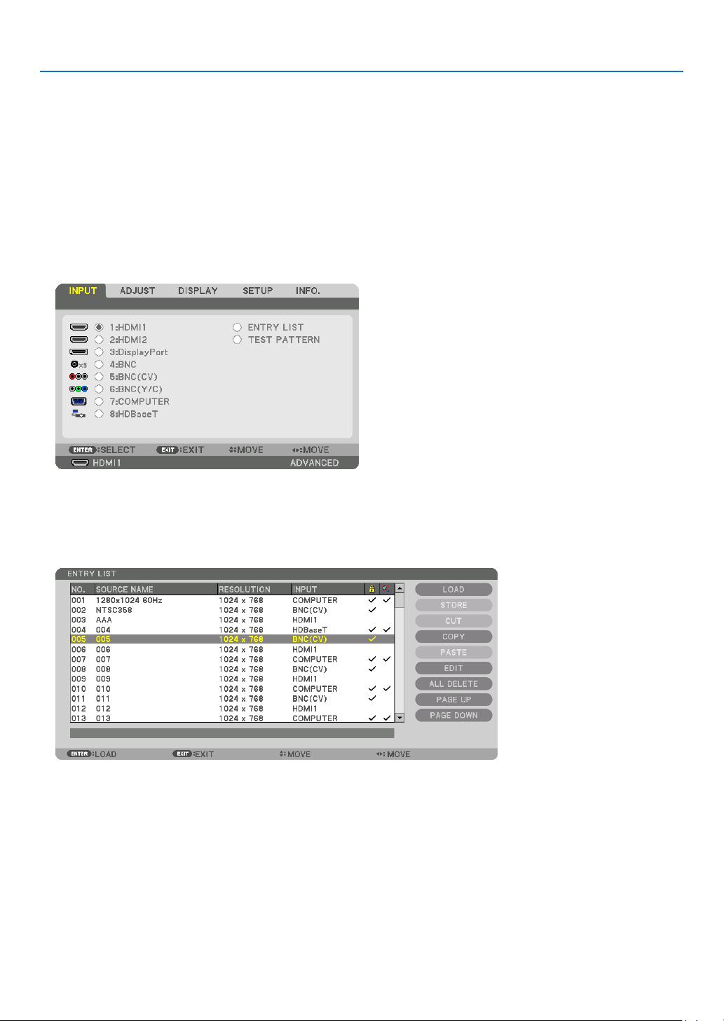
71
5. Using On-Screen Menu
UsingtheEntryList
Whenanysourceadjustmentsaremade,theadjustmentsareautomaticallyregisteredintheEntryList.The(adjust-
mentvaluesof)registeredsignalscanbeloadedfromtheEntryListwhenevernecessary.
However,onlyupto100patternscanberegisteredintheEntryList.When100patternshavebeenregisteredinthe
EntryList,anerrormessageisthendisplayedandnoadditionalpatternscanberegistered.Youshouldthusdelete
(adjustmentvaluesof)signalsthatarenolongerneeded.
DisplayingtheEntrylist
1. Press the MENU button.
Themenuwillbedisplayed.
2. Press the ◀ or ▶buttontoselect[INPUT].
TheINPUTlistwillbedisplayed.
3. Use the ◀, ▶, ▲, or ▼toselect[ENTRYLIST]andpresstheENTERbutton.
TheENTRYLISTwindowswillbedisplayed.
IftheENTRYLISTwindowisnotdisplayed,switchthemenuto[ADVANCED].
Toswitchthemenubetween[ADVANCED]and[BASIC],select[SETUP]→[CONTROL]→[TOOLS]→[ADMIN-
ISTRATORMODE]→[MENUMODE].(→page99)
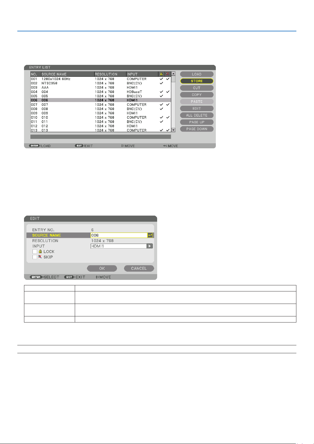
72
5. Using On-Screen Menu
EnteringthecurrentlyprojectedsignalintotheEntryList[STORE]
1. Press the ▲ or ▼ button to select any number.
2. Press the ◀ or ▶buttontoselect[STORE]andpresstheENTERbutton.
CallingupasignalfromtheEntryList[LOAD]
Pressthe▲ or ▼buttontoselectasignalandpresstheENTERbutton.
EditingasignalfromtheEntryList[EDIT]
1. Press the ▲ or ▼ button to select a signal you wish to edit.
2. Press the ◀, ▶, ▲, or ▼buttontoselect[EDIT]andpresstheENTERbutton.
TheEditwindowwillbedisplayed.
SOURCENAME Enterasignalname.Upto18alphanumericcharacterscanbeused.
INPUT Theinputterminalcanbechanged.SwitchingbetweenHDMI1/HDMI2/DisplayPort/BNC/
BNC(CV)/BNC(Y/C)/Computerispossible.
LOCK Set so that the selectedsignalcannot be deleted when [ALL DELETE] is executed.The
changesmadeafterLOCKexecutioncannotbesaved.
SKIP Setsothattheselectedsignalwillbeskippedduringautosearch.
3. Settheaboveitemsandselect[OK]andpresstheENTERbutton.
NOTE: The input terminal cannot be changed to the currently projected signal.

73
5. Using On-Screen Menu
CuttingasignalfromtheEntryList[CUT]
1. Press the ▲ or ▼ button to select a signal you wish to delete.
2. Press the ◀, ▶, ▲, or ▼buttontoselect[CUT]andpresstheENTERbutton.
ThesignalwillbedeletedfromtheEntryListandthedeletedsignalwillbedisplayedontheclipboardatthebottom
oftheEntryList.
NOTE:
• Thecurrentlyprojectedsignalcannotbedeleted.
• Whenthelockedsignalisselected,itwillbedisplayedingraywhichindicatesitisnotavailable.
TIP:
• DataontheclipboardcanbepassedontotheEntryList.
• DataontheclipboardwillnotbelostaftertheEntryListisclosed.
CopyingandpastingasignalfromtheEntryList[COPY]/[PASTE]
1. Press the ▲ or ▼ button to select a signal you wish to copy.
2. Press the ◀, ▶, ▲, or ▼buttontoselect[COPY]andpresstheENTERbutton.
ThecopiedsignalwillbedisplayedontheclipboardatthebottomoftheEntryList.
3. Press the ◀ or ▶ button to move to the list.
4. Press the ▲ or ▼ button to select a signal.
5. Press the ◀, ▶, ▲, or ▼buttontoselect[PASTE]andpresstheENTERbutton.
Dataontheclipboardwillbepastedtothesignal.
DeletingallthesignalsfromtheEntryList[ALLDELTE]
1. Press the ◀, ▶, ▲, or ▼buttontoselect[ALLDELETE]andpresstheENTERbutton.
Theconrmationmessagewillbedisplayed.
2. Press the ◀ or ▶buttontoselect[YES]andpresstheENTERbutton.
NOTE: The locked signal cannot be deleted.
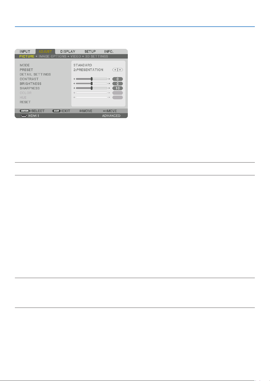
74
5. Using On-Screen Menu
❺ Menu Descriptions & Functions [ADJUST]
[PICTURE]
[MODE]
Thisfunctionallowsyoutodeterminehowtosavesettingsfor[DETAILSETTINGS]of[PRESET]foreachinput.
STANDARD ������������ Saves settings for each item of [PRESET] (Preset 1 through 7)
PROFESSIONAL
����� Saves all the settings of [PICTURE] for each input�
NOTE:
• When[TESTPATTERN]isdisplayed,[MODE]cannotbeselected.
[PRESET]
Thisfunctionallowsyoutoselectoptimizedsettingsforyourprojectedimage.
Youcanadjustneutraltintforyellow,cyanormagenta.
Therearesevenfactorypresetsoptimizedforvarioustypesofimages.Youcanalsouse[DETAILSETTINGS]toset
useradjustablesettingstocustomizeeachgammaorcolor.
Yoursettingscanbestoredin[PRESET1]to[PRESET7].
HIGH-BRIGHT �������� Recommended for use in a brightly lit room�
PRESENTATION ����� Recommended for making a presentation using a PowerPoint file�
VIDEO �������������������� Recommended for typical TV program viewing�
MOVIE ������������������� Recommended for movies�
GRAPHIC ��������������� Recommended for graphics�
sRGB ��������������������� Standard color values
DICOM SIM� ���������� Recommended for DICOM simulation format�
NOTE:
• The[DICOMSIM.]optionisfortraining/referenceonlyandshouldnotbeusedforactualdiagnosis.
• DICOMstandsforDigitalImagingandCommunicationsinMedicine.ItisastandarddevelopedbytheAmericanCollegeofRadiol-
ogy(ACR)andtheNationalElectricalManufacturersAssociation(NEMA).
Thestandardspecieshowdigitalimagedatacanbemovedfromsystemtosystem.
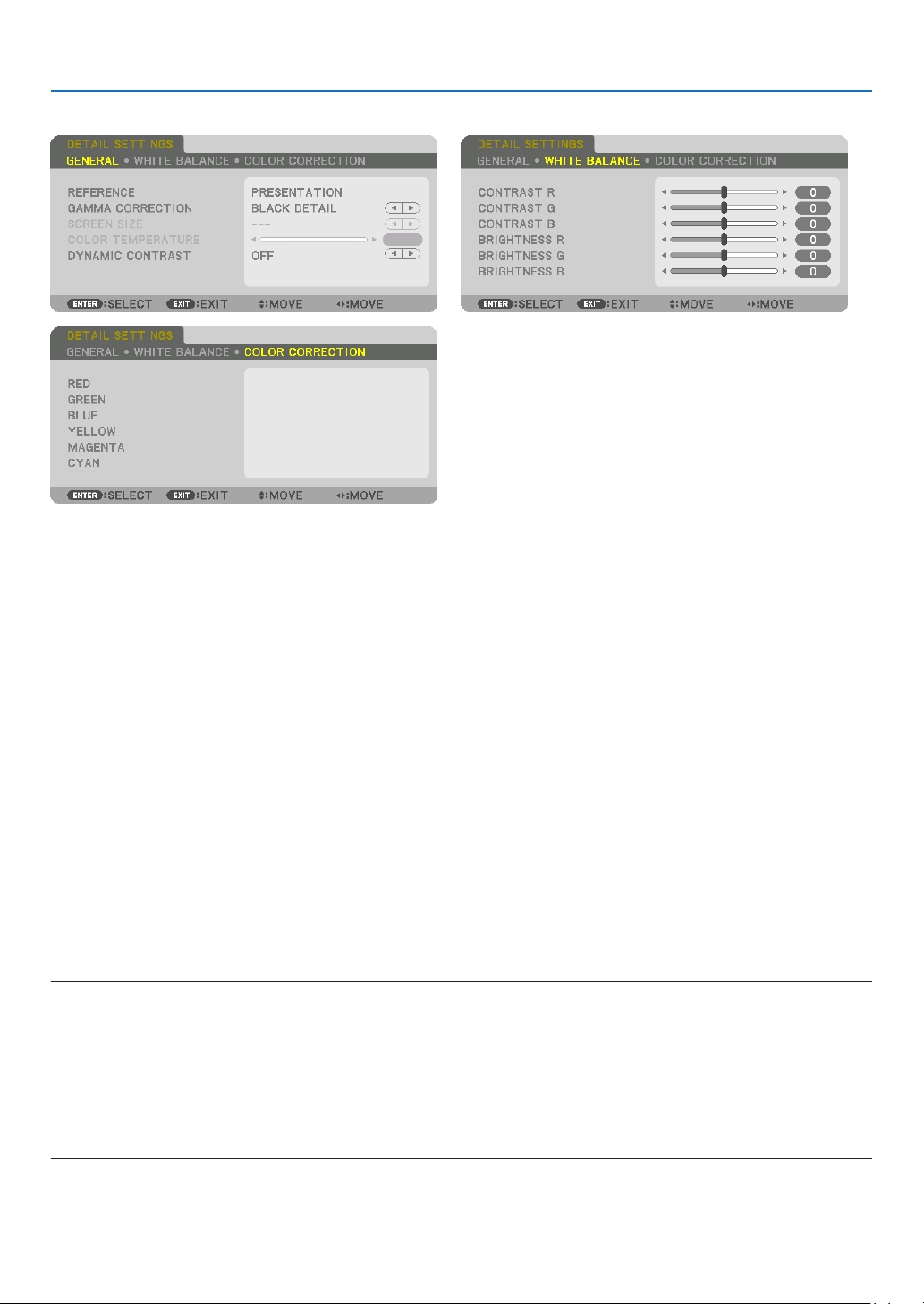
75
5. Using On-Screen Menu
[DETAIL SETTINGS]
[GENERAL]
Storing Your Customized Settings [REFERENCE]
Thisfunctionallowsyoutostoreyourcustomizedsettingsin[PRESET1]to[PRESET7].
First,selectabasepresetmodefrom[REFERENCE],thenset[GAMMACORRECTION]and[COLORTEMPERA-
TURE].
HIGH-BRIGHT �������� Recommended for use in a brightly lit room�
PRESENTATION ����� Recommended for making a presentation using a PowerPoint file�
VIDEO �������������������� Recommended for typical TV program viewing�
MOVIE ������������������� Recommended for movies�
GRAPHIC ��������������� Recommended for graphics�
sRGB ��������������������� Standard color values�
DICOM SIM� ���������� Recommended for DICOM simulation format�
Selecting Gamma Correction Mode [GAMMA CORRECTION]
Eachmodeisrecommendedfor:
DYNAMIC �������������� Creates a high-contrast picture�
NATURAL ��������������� Natural reproduction of the picture�
BLACK DETAIL ������� Emphasizes detail in dark areas of the picture�
NOTE:Thisfunctionisnotavailablewhen[DICOMSIM.]isselectedfor[DETAILSETTINGS].
Selecting Screen Size for DICOM SIM [SCREEN SIZE]
Thisfunctionwillperformgammacorrectionappropriateforthescreensize.
LARGE ������������������� For screen size of 150"
MEDIUM
���������������� For screen size of 100"
SMALL
������������������� For screen size of 50"
NOTE:Thisfunctionisavailableonlywhen[DICOMSIM.]isselectedfor[DETAILSETTINGS].

76
5. Using On-Screen Menu
Adjusting Color Temperature [COLOR TEMPERATURE]
Thisoptionallowsyoutoselectthecolortemperatureofyourchoice.
Avaluebetween5000Kand10500Kcanbesetin100Kunits.
NOTE:When[PRESENTATION]or[HIGH-BRIGHT]isselectedin[REFERENCE],thisfunctionisnotavailable.
Adjusting Brightness and Contrast [DYNAMIC CONTRAST]
Whenset,themostoptimalcontrastratioisadjustedaccordingtothevideo.
OFF ������������������������ Dynamic contrast is disabled�
MOTION IMAGE ����� Most optimal settings for moving images�
STILL IMAGE ��������� Most optimal settings for static images� Rapidly follows any changes in the video�
NOTE:
• Dependingontheconditions,projectorsettingssuchas[DYNAMICCONTRAST]maynotbeabletobeselected.
Adjusting White Balance [WHITE BALANCE]
Thisallowsyoutoadjustthewhitebalance.Contrastforeachcolor(RGB)toadjustthewhitelevelofthescreen;
Brightnessforeachcolor(RGB)isusedtoadjusttheblacklevelofthescreen.
[COLOR CORRECTION]
Correctsthecolorforallsignals.
Adjuststhetoneforthecolorsred,green,blue,yellow,magentaandcyan.
RED HUE +Direction Magentadirection
−Direction Yellowdirection
SATURATION +Direction Vivid
−Direction Weak
GREEN HUE
+Direction Yellowdirection
−Direction Cyandirection
SATURATION +Direction Vivid
−Direction Weak
BLUE HUE
+Direction Cyandirection
−Direction Magentadirection
SATURATION +Direction Vivid
−Direction Weak
YELLOW HUE
+Direction Reddirection
−Direction Greendirection
SATURATION +Direction Vivid
−Direction Weak
MAGENTA HUE
+Direction Bluedirection
−Direction Reddirection
SATURATION +Direction Vivid
−Direction Weak
CYAN HUE
+Direction Greendirection
−Direction Bluedirection
SATURATION +Direction Vivid
−Direction Weak
[CONTRAST]
Adjuststheintensityoftheimageaccordingtotheincomingsignal.
[BRIGHTNESS]
Adjuststhebrightnesslevelorthebackrasterintensity.
[SHARPNESS]
Controlsthedetailoftheimage.

77
5. Using On-Screen Menu
[COLOR]
Increasesordecreasesthecolorsaturationlevel.
[HUE]
Variesthecolorlevelfrom+/−greento+/−blue.Theredlevelisusedasreference.
Inputsignal CONTRAST BRIGHTNESS SHARPNESS COLOR HUE
RGBsystemof“COMPUTER/Display-
Port/HDMI/HDBaseT”
Yes Yes Yes No No
COMPONENTsystemof“COMPUTER/
DisplayPort/HDMI/HDBaseT”
Yes Yes Yes Yes Yes
CompositeVideo/S-Video Yes Yes Yes Yes Yes
Yes=Adjustable,No=Notadjustable
NOTE:
• When[TESTPATTERN]isdisplayed,[CONTRAST],[BRIGHTNESS],[SHARPNESS],[COLOR]and[HUE]cannotbeadjusted.
[RESET]
Thesettingsandadjustmentsfor[PICTURE]willbereturnedtothefactorysettingswiththeexceptionofthefollowing;
Presetnumbersand[REFERENCE]withinthe[PRESET]screen.
Thesettingsandadjustmentsunder[DETAILSETTINGS]withinthe[PRESET]screenthatarenotcurrentlyselected
willnotbereset.
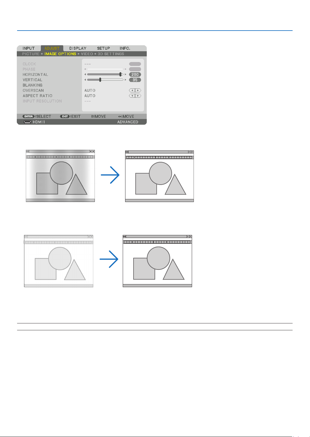
78
5. Using On-Screen Menu
[IMAGE OPTIONS]
AdjustingClockandPhase[CLOCK/PHASE]
ThisallowsyoutomanuallyadjustCLOCKandPHASE.
CLOCK ������������������� Use this item to fine tune the computer image or to remove any vertical banding that might appear� This
function adjusts the clock frequencies that eliminate the horizontal banding in the image�
This adjustment may be necessary when you connect your computer for the first time�
PHASE ������������������� Use this item to adjust the clock phase or to reduce video noise, dot interference or cross talk� (This is
evident when part of your image appears to be shimmering�)
Use [PHASE] only after the [CLOCK] is complete�
NOTE:The[CLOCK]and[PHASE]itemsareavailableforRGBsignalsonly.
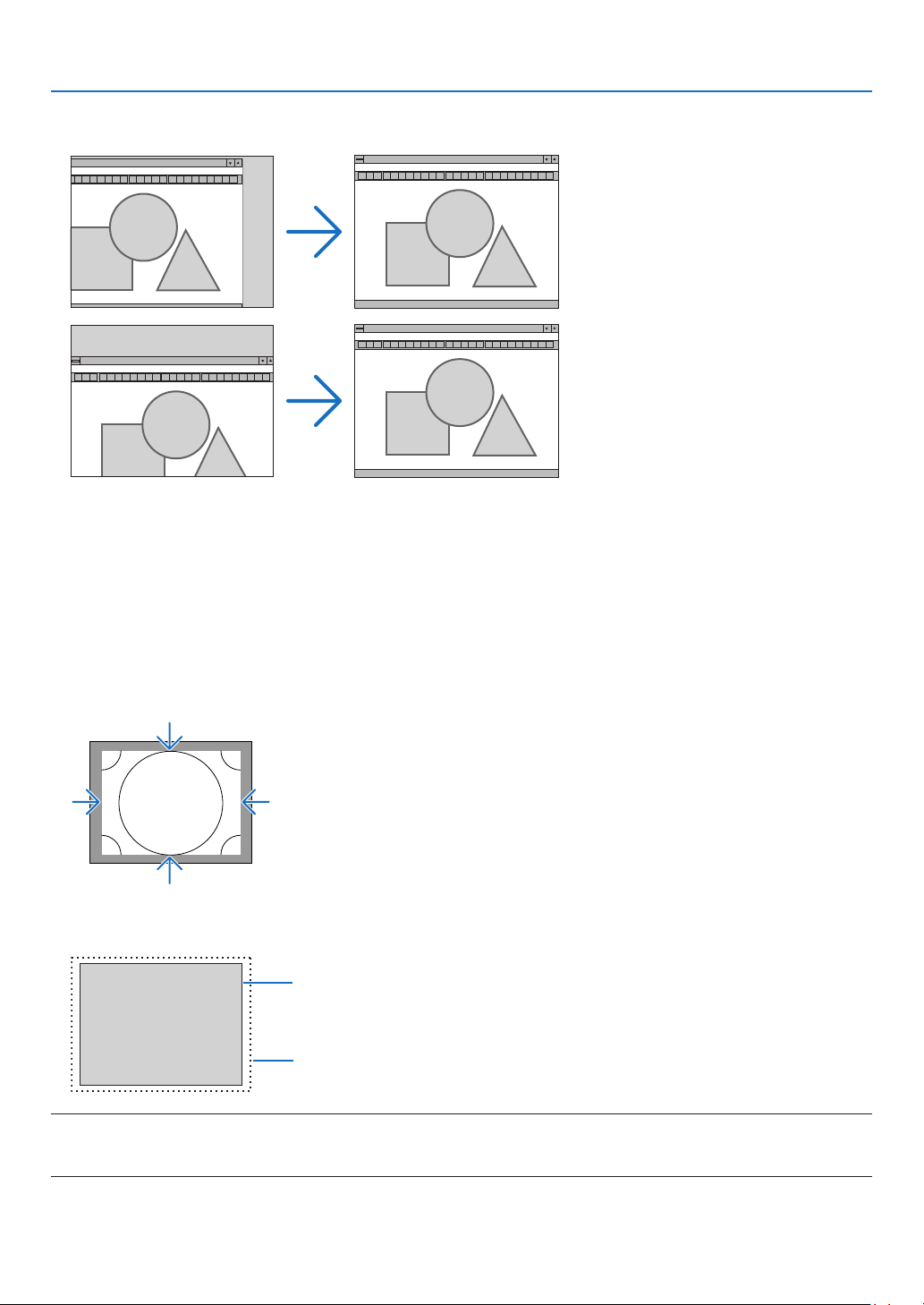
79
5. Using On-Screen Menu
AdjustingHorizontal/VerticalPosition[HORIZONTAL/VERTICAL]
Adjuststheimagelocationhorizontallyandvertically.
• Animagecanbedistortedduringtheadjustmentof[CLOCK]and[PHASE].Thisisnotmalfunction.
• Theadjustments for[CLOCK],[PHASE], [HORIZONTAL],and[VERTICAL]willbestoredinmemoryforthe
currentsignal.Thenexttimeyouprojectthesignalwiththesameresolution,horizontalandverticalfrequency,
itsadjustmentswillbecalledupandapplied.
Todeleteadjustmentsstoredinmemory,fromthemenu,youselect[RESET]→[CURRENTSIGNAL]andreset
theadjustments.
[BLANKING]
Adjuststhedisplayrange(blanking)atthetop,bottom,leftandrightedgesoftheinputsignal.
SelectingOverscanPercentage[OVERSCAN]
Selectoverscanpercentage(Auto,0%,5%and10%)forsignal.
Projectedimage
Overscanedby10%
NOTE:
• The[OVERSCAN]itemisnotavailable:
-when[NATIVE]isselectedfor[ASPECTRATIO].

80
5. Using On-Screen Menu
Selecting the Aspect Ratio [ASPECT RATIO]
Usethisfunctiontoselectthescreen’svertical:horizontalaspectratio.
Selectthescreentype(4:3screen,16:9screenor16:10screen)atthescreensettingbeforesettingtheaspectratio.
(→page97)
Theprojectorautomaticallyidentiesthesignalbeinginputandsetstheoptimumaspectratio.
For Computer signal
ForComponent/Video/S-Videosignals
Whenthescreentypeissetto4:3 Whenthescreentypeissetto16:9or16:10
Resolution AspectRatio
VGA 640×480 4:3
SVGA
800×600 4:3
XGA
1024×768 4:3
WXGA
1280×768 15:9
WXGA
1280×800 16:10
HD(FWXGA)
1366×768 approx.16:9
WXGA+ 1440×900 16:10
SXGA
1280×1024 5:4
SXGA+
1400×1050 4:3
WXGA++
1600×900 16:9
UXGA
1600×1200 4:3
WSXGA+
1680×1050 16:10
FHD(1080P)
1920×1080 16:9
WUXGA
1920×1200 16:10
WQXGA
2560×1600 16:10
Options Function
AUTO
Theprojectorwillautomaticallydeterminetheincomingsignalanddisplayitinitsaspectratio.
Theprojectormayerroneouslydeterminetheaspectratiodependingonitssignal.Ifthisoccurs,select
theappropriateaspectratiofromthefollowing.
4:3 Theimageisdisplayedin4:3aspectratio.
5:4 Theimageisdisplayedin5:4aspectratio
16:9 Theimageisdisplayedin16:9aspectratio
15:9 Theimageisdisplayedin15:9aspectratio
16:10 Theimageisdisplayedin16:10aspectratio
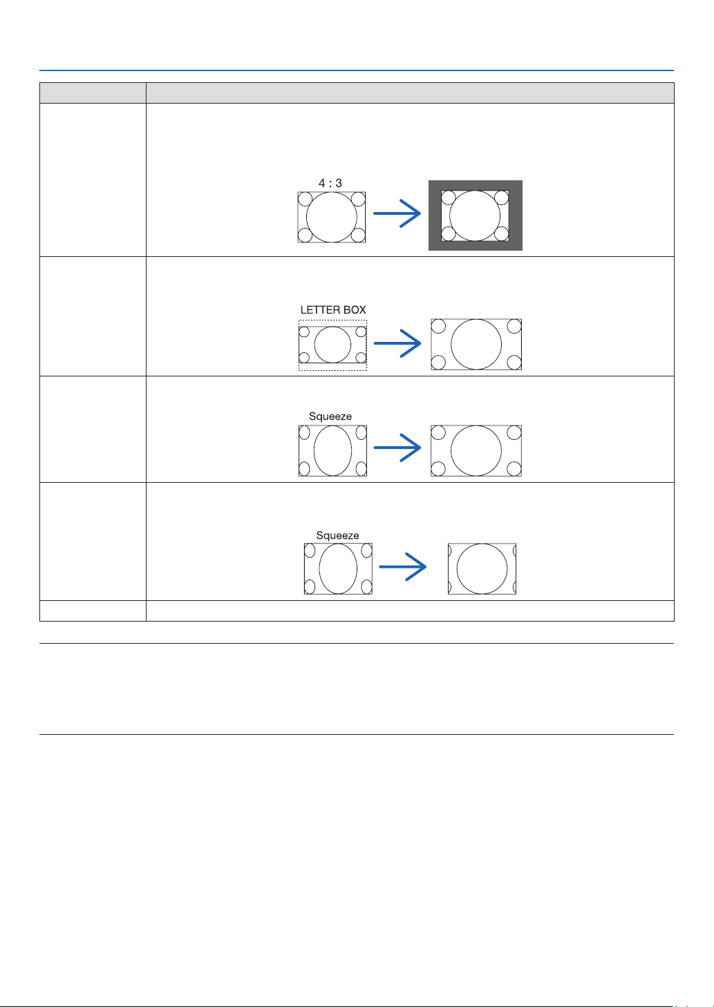
81
5. Using On-Screen Menu
Options Function
NATIVE
Theprojectordisplaysthecurrentimageinitstrueresolutionwhentheincomingcomputersignalhasa
lowerorhigherresolutionthantheprojector’snativeresolution.(→page2)
Whentheincomingcomputersignalhasahigherresolutionthantheprojector'snativeresolution,the
centerofanimagewillbedisplayed.
LETTERBOX Theimageofaletterboxsignal(16:9)isstretchedequallyinthehorizontalandverticaldirectionstotthe
screen.
WIDESCREEN Theimageofasqueezesignal(16:9)isstretchedleftandrightin16:9.
ZOOM Theimageofasqueezesignal(16:9)isstretchedleftandrightin4:3.
Partsofthedisplayedimagearecroppedattheleftandrightedgesandthereforenotvisible.
FULL Projecttofullscreensize.
TIP:
• Imagepositioncanbeadjustedverticallyusing[POSITION]whenthe[16:9],[15:9],or[16:10]aspectratiosareselected.
• Theterm“letterbox”referstoamorelandscape-orientedimagewhencomparedtoa4:3image,whichisthestandardaspect
ratio for a vide source.
Theletterboxsignalhasaspectratioswiththevistasize“1.85:1”orcinemascopesize“2.35:1”formovielm.
• Theterm“squeeze”referstothecompressedimageofwhichaspectratioisconvertedfrom16:9to4:3.
[INPUT RESOLUTION]
Theresolutionisassignedautomaticallywhentheresolutionoftheinputsignalfromthecomputervideoinputterminal
orBNCvideoinputterminal(analogRGB)cannotbedistinguished.

82
5. Using On-Screen Menu
[VIDEO]
Using Noise Reduction [NOISE REDUCTION]
Whenprojectingavideoimage,youcanusethe[NOISEREDUCTION]functiontoreducethescreennoise(roughness
anddistortion).Thisdeviceisequippedwiththreetypesofnoisereductionfunctions.Selectthefunctionaccordingto
thetypeofnoise.Dependingonthenoiselevel,thenoisereductioneffectcanbesetto[OFF],[LOW],[MEDIUM]or
[HIGH].[NOISEREDUCTION]canbeselectedforSDTV,HDTVsignalandcomponentsignalinput.
RANDOM NR ��������� Reduces flickering random noise in an image�
MOSQUITO NR ������ Reduces mosquito noise that appears around the edges of an image during Blu-ray playback�
BLOCK NR ������������� Reduces block noise or mosaic-like patterns by selecting ON�
Selecting Interlaced Progressive Conversion Process Mode [DEINTERLACE]
Thisfunctionallowsyoutoselectaninterlaced-to-progressiveconversionprocessforvideosignals.
NORMAL ���������������� Automatically distinguishes a moving image from a static image to create a distinct image� Please select
[MOVIE] if there are any obvious jitter and noises�
MOVIE ������������������� Select when projecting moving images� This is suitable for signals with a lot of jitter and noise�
STILL ��������������������� Select when projecting static images� The video will flicker when a moving image is projected�
NOTE:ThisfunctionisnotavailablewithRGBsignals.
[CONTRAST ENHANCEMENT]
Usingthecharacteristicsofthehumaneye,apicturequalitywithasenseofcontrastandresolutionisachieved.
OFF ������������������������ Suite vision is switched off�
AUTO ��������������������� Contrast and picture quality are automatically improved using the suite vision function�
NORMAL ���������������� Adjust the gain manually�

83
5. Using On-Screen Menu
[SIGNAL TYPE]
SelectionofRGBandcomponentsignals.Normally,thisissetto[AUTO].Pleasechangethesettingifthecolorofthe
imageremainsunnatural.
AUTO ��������������������� Automatically distinguishes RGB and component signals�
RGB ����������������������� Switches to the RGB input�
COMPONENT ��������� Switches to the component signal input�
[VIDEOLEVEL]
SelectionofthevideosignallevelwhenconnectinganexternaldevicetotheHDMI1INterminal,HDMI2INterminal,
DisplayPortinputterminal,andHDBaseTinputterminaloftheprojector.
AUTO ��������������������� The video level is switched automatically based on the information from the device outputting the signal�
Depending on the connected device, this setting may not be made properly� In this case, switch to [NORMAL”
or “ENHANCED” from the menu and view with the optimum setting�
NORMAL ���������������� This disables the enhanced mode�
ENHANCED ������������ This improves the image’s contrast, expressing the dark and light sections more dynamically�
SUPER WHITE ������� The video contrast is improved and the dark areas appear more dynamic�

84
5. Using On-Screen Menu
[3D SETTINGS]
Pleasereferto“3-8Projecting3Dvideos”(→page39)fortheoperation.
STEREOVIEWER
Stackupasingleormultipleprojectorsandcarryoutthesettingsforprojecting3Dvideos.Selecttheleft/rightset-
tingsofthe3Deyewearusingthestereoviewer.
SINGLE ������������������ Use a single projector to project 3D videos�
DUAL LEFT ������������ Use a dedicated projector for displaying videos on the left�
DUAL RIGHT ���������� Use a dedicated projector for displaying videos on the right�
STEREO FILTER
Stackupasingleormultipleprojectorsandcarryoutthesettingsforprojecting3Dvideos.Imagesettingfor3Dglasses
madebyIntec.
SINGLE ������������������ Use a single projector to project 3D videos�
DUAL LEFT ������������ Use a dedicated projector for displaying videos on the left�
DUAL RIGHT ���������� Use a dedicated projector for displaying videos on the right�
FORMAT
Selectthe3Dvideoformat(recording/transmissionformat).Selecttomatchthe3Dbroadcastand3Dmedia.Nor-
mally,[AUTO]isselected.Pleaseselectthe3Dinputsignalformatwhenthe3Ddetectionsignaloftheformatcannot
bedistinguished.
L/RINVERT
Invertthedisplayorderoftheleftandrightvideos.
Select[ON]ifyoufeeluncomfortablewiththe3Ddisplaywhen[OFF]isselected.
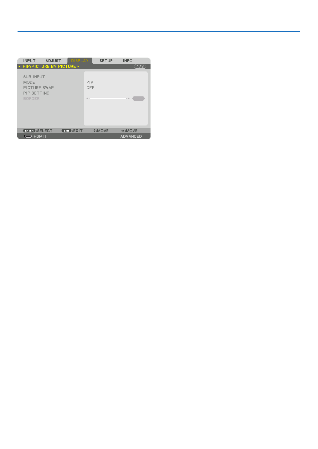
85
5. Using On-Screen Menu
❻ Menu Descriptions & Functions [DISPLAY]
[PIP/PICTURE BY PICTURE]
SUB INPUT
Selecttheinputsignaltobedisplayedinthesub-display.
Pleasereferto“4-2DisplayingTwoPicturesattheSameTime”(→page52)fordetailsontheoperation.
MODE
SelecteitherPIPorPICTUREBYPICTUREwhenswitchingto2-screendisplay.
PICTURE SWAP
Thevideosinthemaindisplayandsub-displaywillbeswitched.
Pleasereferto“4-2DisplayingTwoPicturesattheSameTime”(→page54)fordetails.
PIP SETTING
Selectthedisplayposition,positionadjustmentandsizeofthesub-displayinthePIPscreen.
START POSITION ��� Selection of the display position of the sub-display when switching to the PIP screen�
HORIZONTAL POSITION
������������������������������ Adjust the display position of the sub-display in the horizontal direction� The respective corners will serve
as reference points�
VERTICAL POSITION
������������������������������ Adjust the display position of the sub-display in the vertical direction� The respective corners will serve as
reference points�
SIZE ����������������������� Select the display size of the sub-display�
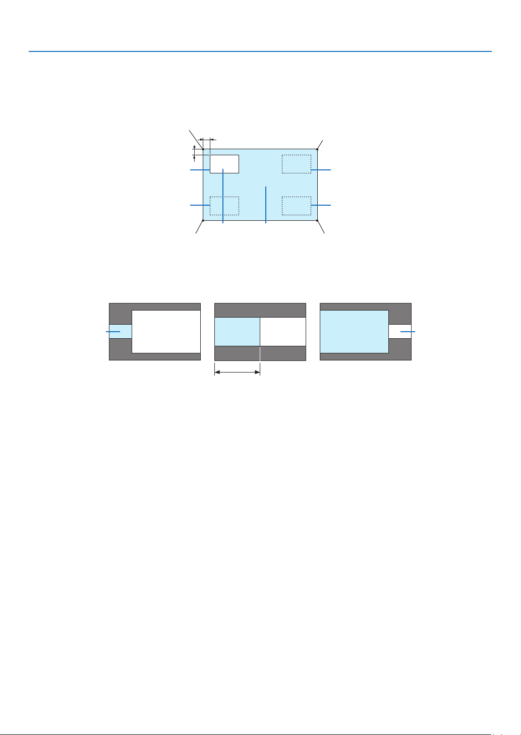
86
5. Using On-Screen Menu
TIP:
Thehorizontalpositionandverticalpositionaretheamountofmovementfromthereferencepoints.Forexample,whenTOP-LEFT
is adjusted, the position is displayed with the same amount of movement even if displayed with other starting positions.
The maximum amount of movement is half the resolution of the projector.
Referencepoint
Adjustusingthehorizon-
talposition
Sub-display Maindisplay
Referencepoint
Adjustusingtheverticalposition
TOP-LEFT TOP-RIGHT
BOTTOM-LEFT BOTTOM-RIGHT
ReferencepointReferencepoint
BORDER
Selectthedisplayboundaryofthemaindisplayandsub-displayofthe[PICTUREBYPICTURE]screen.
Displayboundary
Maindisplay
Sub-displayMaindisplay
Sub-display
MaindisplaySub-display
TIP:
• ForPA622U/PA522U,sixstagescanbeselected.
• ForPA672W/PA572W/PA722X/PA622X,threestagescanbeselected.
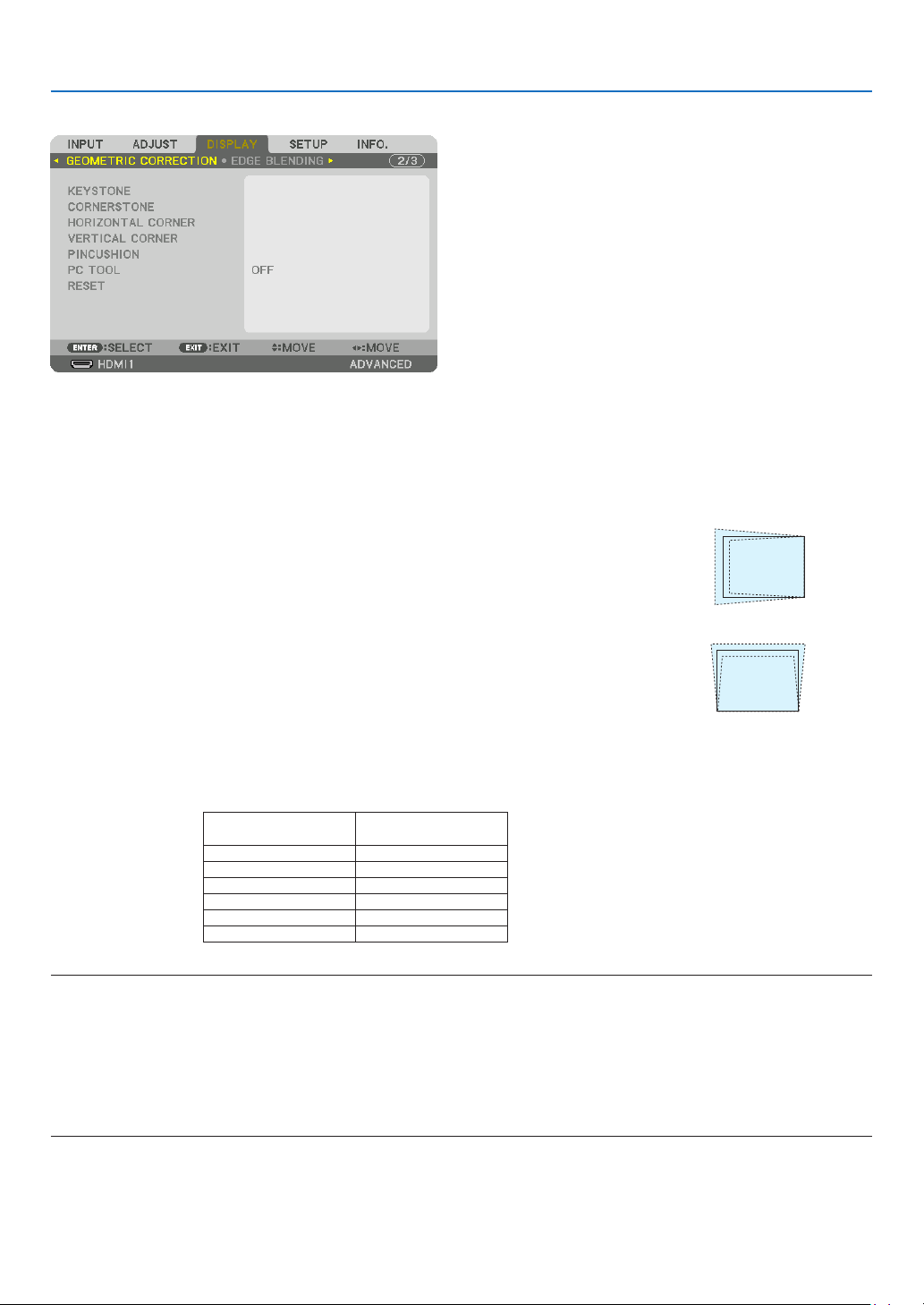
87
5. Using On-Screen Menu
[GEOMETRIC CORRECTION]
KEYSTONE
Displaythetrapezoidcorrectionscreenandadjustthetrapezoidaldistortionoftheprojectionscreen.
Todisplaythe[KEYSTONE]screen,select→[DISPLAY]→[GEOMETRICCORRECTION]→[KEYSTONE]inthe
on-screenmenu.The[GEOMETRICCORRECTION]screencanalsobedisplayedbypressingtheGeometric.button
ontheremotecontrol.
HORIZONTAL ��������� Adjustments when projecting from a diagonal direction to the
screen�
VERTICAL �������������� Adjustments when projecting from the top or bottom direction to
the screen�
TILT ����������������������� Adjusts the distortion when performing trapezoidal correction with the screen moved in the vertical direction
using the lens shift�
THROW RATIO ������� Adjusts according to the projection ratio of the optional lens used�
Modelnameoflens
unit
Adjustmentrange
NP11FL 8
NP30ZL 8–10
NP12ZL 12–15
NP13ZL 15–30
NP14ZL 29–47
NP15ZL 46–71
NOTE:
• Whenpowerissuppliedtothedevice,theadjustmentvalueofthe[KEYSTONE]usedpreviouslyisretainedevenifthegradient
of the device is changed.
• Whenclearingtheadjustmentvalueof[KEYSTONE],presstheGeometric.buttonfor2ormoreseconds.
• Whensettingother[GEOMETRICCORRECTION]functions,the[KEYSTONE]menucannotbeselected.Whenperformingtrapezoidal
correction,presstheGeometric.buttonfor2ormoresecondstocleartheadjustmentvalueof[GEOMETRICCORRECTION].
• Aselectrical correctioniscarriedoutby[KEYSTONE],thebrightnessmaybe reducedorthe screenqualitymay deteriorate
sometimes.
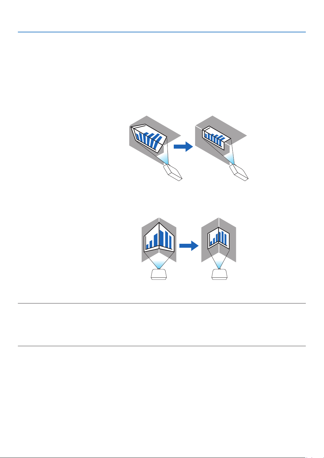
88
5. Using On-Screen Menu
CORNERSTONE
Displaythe4-pointcorrectionscreenandadjustthetrapezoidaldistortionoftheprojectionscreen.
Pleasereferto“CorrectingHorizontalandVerticalKeystoneDistortion[CORNERSTONE]”(→page33)fordetails
ontheoperation.
HORIZONTALCORNER/VERTICALCORNER
Distortioncorrectionforcornerprojectionsuchaswallsurfaces.
HORIZONTAL CORNER
������������������������������ Performs correction for projection onto a wall lying at an angle to the horizontal direction�
* Reverse angle correction is also possible�
VERTICAL CORNER
������������������������������ Performs correction for projection onto a wall lying at an angle to the vertical direction�
* Reverse angle correction is also possible�
NOTE:
• Whenthemaximumadjustmentrangeisexceeded,distortionadjustmentisdisabled.Setuptheprojectoratanoptimalangleas
the deterioration in the image quality increases as the distortion adjustment volume gets larger.
• Pleasenotethattheimagewillgooutoffocusduetothedifferenceinthedistancebetweentheupperandlowerorleftandright
sidesandthecenterofthescreenforprojectionscuttingacrosscorners.Lenseswithshortfocalpointsarealsonotrecommended
for projections cutting across corners as the image will go out of focus.
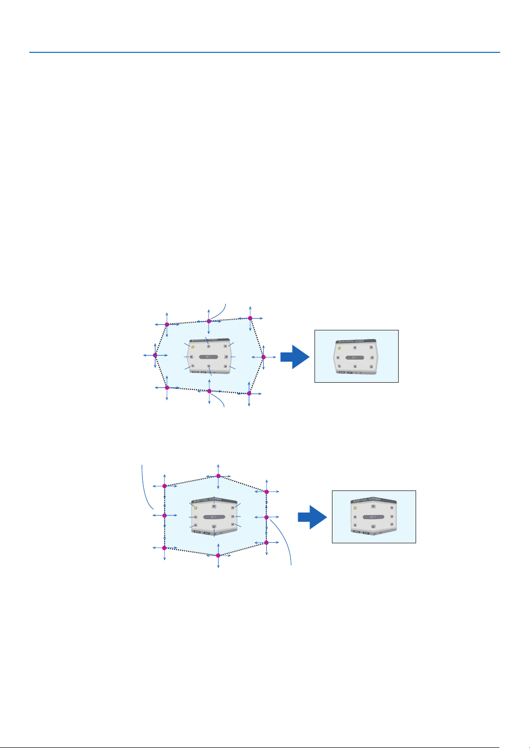
89
5. Using On-Screen Menu
Adjustment method
1. Alignthecursorwiththe[HORIZONTALCORNER]or[VERTICALCORNER]ofthe[GEOMETRICCORREC-
TION]menuandthenpresstheENTERbutton.
• Theadjustmentscreenwillbedisplayed.
2. Press the ▼▲◀▶ buttons to align the cursor (yellow box) with the target adjustment point and then press
the ENTER button.
• Thecursorwillchangeintoanadjustmentpoint(yellowincolor).
3. Press the ▼▲◀▶ buttons to adjust the corners or sides of the screen and then press the ENTER button.
• Theadjustmentpointwillgobacktobeingacursor(yellowbox).
Explanationofscreentransition
• Theadjustmentpointsofthefourcorners(a,c,fandhinthedrawing)willmoveindependently.
• Thefollowingadjustmentpointsdifferatthe[HORIZONTALCORNER]and[VERTICALCORNER].
HORIZONTALCORNER:WhenPointbinthedrawingismoved,andtheuppersideandPointgaremoved,the
lowersidewillmoveinaparallelmanner.
VERTICALCORNER:WhenPointdinthedrawingismoved,andtheleftsideandPointearemoved,theright
sidewillmoveinaparallelmanner.
[Adjustmentpointsofthe[HORIZONTALCORNER]screenandmovementpointsoftheprojectionscreen]
a
b
b
c
d
e
f
g
h
a
c
d
e
f
g
h
PointbwillbedisplacedinaparallelmanneratthesametimeasPointsa,b,c
PointgwillbedisplacedinaparallelmanneratthesametimeasPointsf,g,h
[Adjustmentpointsofthe[VERTICALCORNER]screenandmovementpointsoftheprojectionscreen]
a
a
b
b
c
c
d
d
e
e
f
f
g
g
h
h
PointdwillbedisplacedinaparallelmanneratthesametimeasPointsa,d,f
PointewillbedisplacedinaparallelmanneratthesametimeasPointsf,g,h
4. Start from Step 2 onwards to adjust the other points.
5. When the adjustment is completed, press the ▼▲◀▶buttonsto alignthecursorwiththe[EXIT]inthe
adjustment screen and then press theENTER button.
• Switchtothe[GEOMETRICCORRECTION]menuscreen.

90
5. Using On-Screen Menu
PINCUSHION
Adjustthecurvedistortionoftheprojectionscreen.
TOP ������������������������ Adjust the curve distortion of the upper edge of the projection
screen�
BOTTOM ���������������� Adjust the curve distortion of the lower edge of the projection
screen�
LEFT ���������������������� Adjust the curve distortion of the left edge of the projection
screen�
RIGHT �������������������� Adjust the curve distortion of the right edge of the projection
screen�
TOP
LEFT RIGHT
BOTTOM
PC TOOL
Recallthegeometriccorrectiondatathatisregisteredintheprojectorbeforehand.
Therearethreetypesofregistereddata.
NOTE:
• KEYSTONE,CORNERSTONE,andPINCUSHIONcannotbeselectedwhensettingthegeometriccorrectionusingaPCtool.
• Toclearthe[GEOMETRICCORRECTION]datathathasbeensetup,presstheGeometric.buttonfor2ormoreseconds.
• Aselectricalcorrectioniscarriedoutingeometriccorrection,thebrightnessmaybeaffectedandthepicturequalitymaybe
degraded.
RESET
ResettheadjustmentvaluethathasbeensetupinGEOMETRICCORRECTION(returntotheinitialvalue).

91
5. Using On-Screen Menu
[EDGE BLENDING]
Thisadjuststheedges(boundaries)oftheprojectionscreenwhenprojectinghighresolutionvideosusingacombina-
tionofseveralprojectorsintheup,down,leftandrightpositions.
MODE
ThisenablesordisablestheEDGEBLENDINGfunction.
WhenMODEissettoON,theTOP,BOTTOM,LEFT,RIGHTandBLACKLEVELsettingscanbeadjusted.
TOP/BOTTOM/LEFT/RIGHT
ThisselectstheEDGEBLENDINGlocationsontheleft,right,topandbottomonthescreen.
Thefollowingsettingscanbeadjustedwhenanitemisselected.(→page57)
CONTROL
�������������� Enable TOP, BOTTOM, LEFT and RIGHT functions�
MARKER ���������������� Set whether to display marker or not when adjusting the range and display position� When turned on, a
magenta marker for adjusting the range adjustment and a green marker for adjusting the display position
will be displayed�
RANGE ������������������� Adjust the range (width) of the edge blending�
POSITION �������������� Adjust the display position of the edge blending�
BLACKLEVEL
Dividethescreenintoninepartsandkeeptheblackleveluniformforeachprojector.
TheninedivisionsscreensareTOP-LEFT,TOP-CENTER,TOP-RIGHT,CENTER-LEFT,CENTER,CENTER-RIGHT,
BOTTOM-LEFT,BOTTOM-CENTERandBOTTOM-RIGHT.(→page60)

92
5. Using On-Screen Menu
[MULTI SCREEN]
WHITE BALANCE
Thisadjuststhewhitebalanceforeachprojectorwhenprojectingusingacombinationofseveralprojectors.
Thiscanbeadjustedwhen[MODE]issetto[ON].
BRIGHTNESS W, BRIGHTNESS R, BRIGHTNESS G, BRIGHTNESS B
������������������������������ Adjusting the black color of the video�
CONTRAST W, CONTRAST R, CONTRAST G, CONTRAST B
������������������������������ Adjusting the white color of the video�
PICTURE SETTING
Thissetsthedivisionconditionwhenprojectingusingacombinationofseveralprojectors.
Pleasereferto“4.Multi-ScreenProjection”(→page48)fordetails.
MODE OFF Usetheprojectorinastandalonestate.
ZOOM Thisadjuststhepositionandwidthofthevideoareathatyouwishtodivide.Theedge
blendingwidthwillalsobeautomaticallysettothatwidth.
TILING Thisassignsthedividedscreenstotheprojectors.Theedgeblendingfunctionwillalso
besetautomatically.
ZOOM HORIZONTAL
ZOOM
Thisenlargesthevideoareainthehorizontaldirection.
VERTICAL
ZOOM
Thisenlargesthevideoareaintheverticaldirection.
HORIZONTAL
POSITION
Thisshiftsthevideoareainthehorizontaldirection.
VERTICALPO-
SITION
Thisshiftsthevideoareaintheverticaldirection.
TILING WIDTH Thisselectsthenumberofprojectorstobearrangedhorizontally.
HEIGHT Thisselectsthenumberofprojectorstobearrangedvertically.
HORIZONTAL
POSITION
Thisselectsthepositionoftheprojectorstartingfromtheleftamongthosearranged
horizontally.
VERTICALPO-
SITION
Thisselectsthepositionoftheprojectorstartingfromthetopamongthosearranged
vertically.
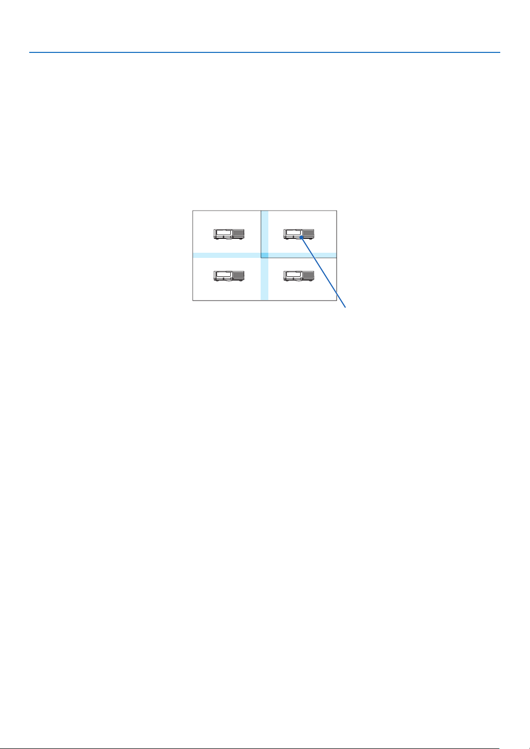
93
5. Using On-Screen Menu
Conditions for using tiling
Alltheprojectorsneedtofullthefollowingconditions.
• Thepanelsizemustbethesame
• Theprojectionscreensizemustbethesame
• Theleftandrightendsortopandbottomendsoftheprojectionscreenmustbeconsistent.
• Thesettingsfortheleftandrightedgesoftheedgeblendingarethesame
• Thesettingsforthetopandbottomedgesoftheedgeblendingarethesame
Ifthetilingconditionsaresatised,thevideoscreenoftheprojectorateachinstallationpositionwillbeautomatically
extractedandprojected.
Ifthetilingconditionsarenotsatised,adjustthevideoscreenoftheprojectorateachinstallationpositionusingthe
zoomfunction.
Tilingsettingexample)Numberofhorizontalunits=2,Numberofverticalunits=2
Horizontalorder=Secondunit
Verticalorder=Firstunit
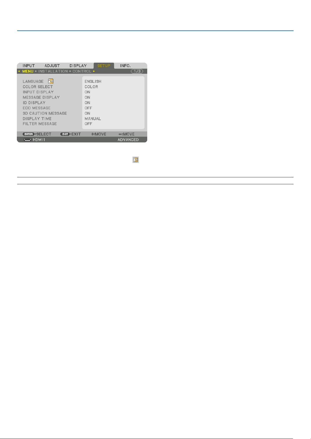
94
5. Using On-Screen Menu
❼ Menu Descriptions & Functions [SETUP]
[MENU]
Selecting Menu Language [LANGUAGE]
Youcanchooseoneof29languagesforon-screeninstructions.
NOTE:Yoursettingwillnotbeaffectedevenwhen[RESET]isdonefromthemenu.
Selecting Menu Color [COLOR SELECT]
Youcanchoosebetweentwooptionsformenucolor:COLORandMONOCHROME.
TurningOn/OffSourceDisplay[INPUTDISPLAY]
ThisoptionturnsonoroffinputnamedisplaysuchasHDMI1,HDMI2,DisplayPort,BNC,BNC(CV),BNC(Y/C),COM-
PUTER,HDBaseTtobedisplayedonthetoprightofthescreen.
Turning messages on and off [MESSAGE DISPLAY]
Thisoptionselectswhetherornottodisplayprojectormessagesatthebottomoftheprojectedimage.
Evenwhen“OFF”isselected,thesecuritylockwarningisdisplayed.Thesecuritylockwarningturnsoffwhenthe
securitylockiscanceled.
TurningON/OFFControlID[IDDISPLAY]
ID DISPLAY ����������� This option turns on or off the ID number which is displayed when the ID SET button on the remote control
is pressed� (→ page 105)
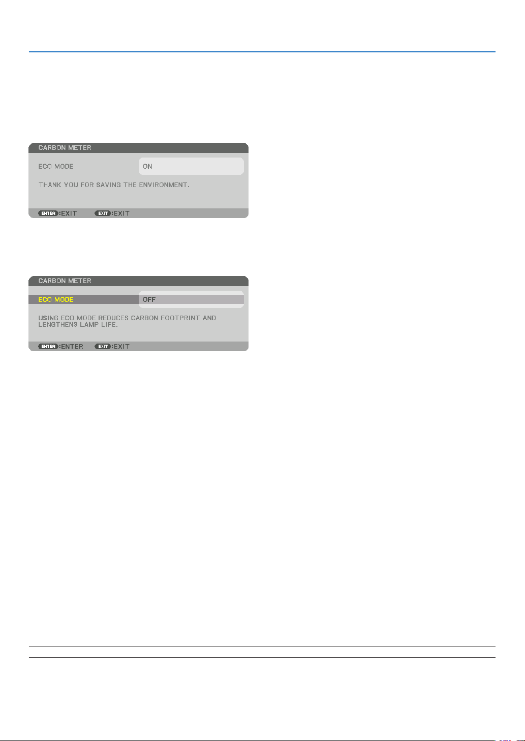
95
5. Using On-Screen Menu
TurningOn/OffEcoMessage[ECOMESSAGE]
Thisoptionturnsonoroffthefollowingmessageswhentheprojectoristurnedon.
TheEcoMessagepromptstheusertosaveenergy.When[OFF]isselectedfor[ECOMODE],youwillgetamessage
topromptyoutoselect[ON]for[ECOMODE].
When[ON]isselectedfor[ECOMODE]
Toclosethemessage,pressanyoneofthebuttons.Themessagewilldisappearifnobuttonoperationisdonefor
30seconds.
When[OFF]isselectedfor[ECOMODE]
PressingtheENTERbuttonwilldisplaythe[ECOMODE]screen.(→page98)
Toclosethemessage,presstheEXITbutton.
[3D CAUTION MESSAGE]
Thisselectswhethertodisplayacautionmessageornotwhenswitchingtoa3Dvideo.
ThedefaultconditionwhenshippedfromthefactoryisON.
OFF ������������������������ The 3D caution message screen will not be displayed�
ON ������������������������� The 3D caution message screen will be displayed when switching to a 3D video� Press the ENTER button
to cancel the message�
• Themessagewilldisappearautomaticallyafter60secondsorwhenotherbuttonsarepressed.Ifitdisap-
pears automatically, the 3D caution message will be displayed again when switching to a 3D video�
SelectingMenuDisplayTime[DISPLAYTIME]
Thisoptionallowsyoutoselecthowlongtheprojectorwaitsafterthelasttouchofabuttontoturnoffthemenu.The
presetchoicesare[MANUAL],[AUTO5SEC],[AUTO15SEC],and[AUTO45SEC].The[AUTO45SEC]isthefac-
torypreset.
Selecting Interval Time for Filter Message [FILTER MESSAGE]
Thisoptionallowsyoutoselectthetimepreferencebetweendisplayingthemessageforcleaningthelters.Clean
thelterwhenyougetthemessage“PLEASECLEANFILTER.”(→page138)
Fiveoptionsareavailable:OFF,100[H],500[H],1000[H],2000[H]
Thedefaultsettingis[OFF].
NOTE:Yoursettingwillnotbeaffectedevenwhen[RESET]isdonefromthemenu.
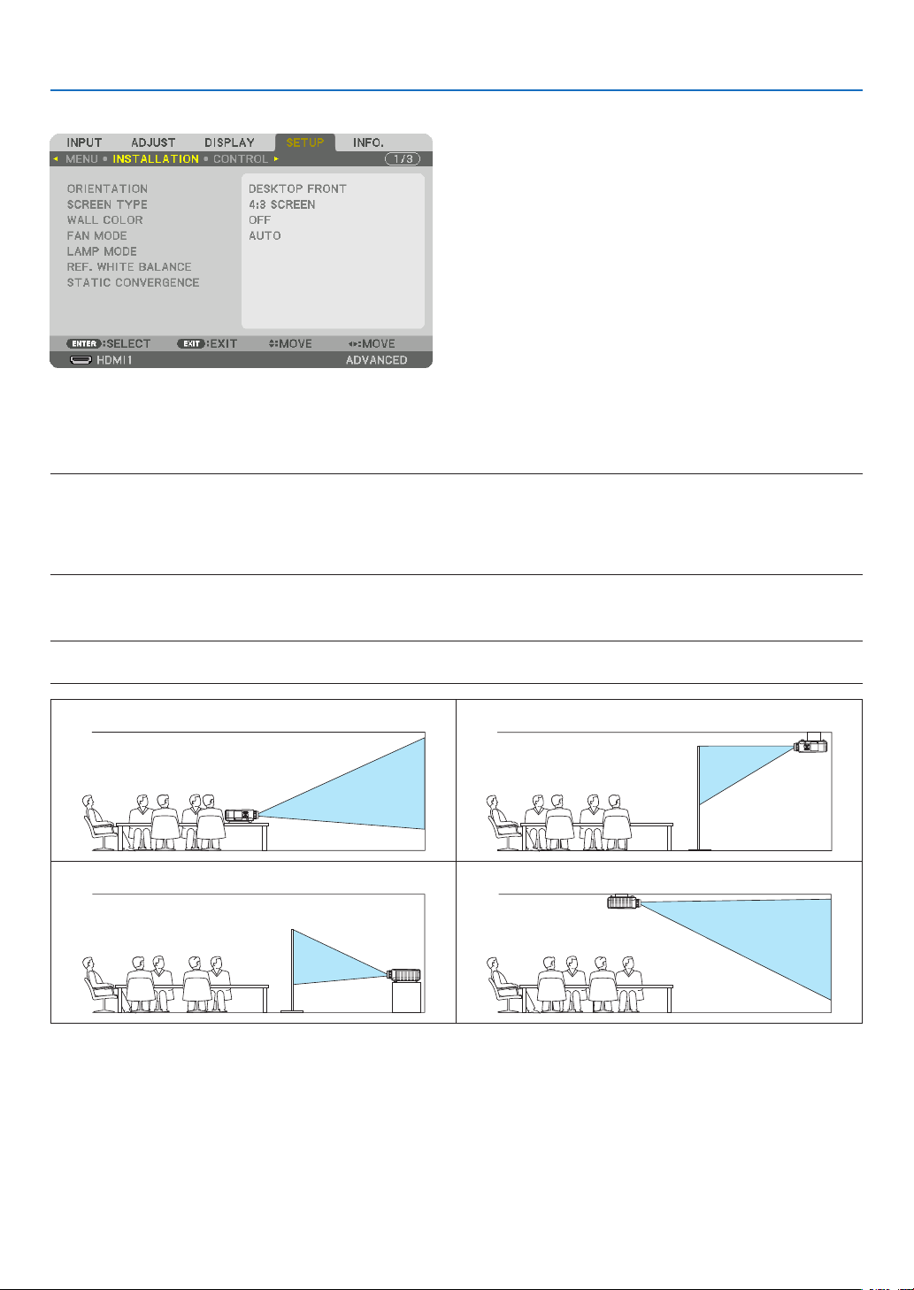
96
5. Using On-Screen Menu
[INSTALLATION]
Selecting Projector Orientation [ORIENTATION]
Thisreorientsyourimageforyourtypeofprojection.Theoptionsare:desktopfrontprojection,ceilingrearprojection,
desktoprearprojection,andceilingfrontprojection.
NOTE:
• Pleaseconsulttheretailstoreifyourequirespecialinstallationservicese.g.whenmountingtheprojectortoaceiling.Neverinstall
the projector on your own. This may result in the projector falling down and causing injury to people.
• Whenusingtheprojectorsuspendedfromaceiling,ensurethatpeopledonotstaybelowtheprojector.Intheeventthelamp
were to break, there is a risk that glass fragments may fall from the projector.
AUTO
��������������������� This automatically detects and projects the DESKTOP FRONT and CEILING FRONT�
NOTE:
• TheDESKTOPREARandCEILINGREARwillnotbedetected.Pleaseselectmanually.
DESKTOPFRONT CEILINGREAR
DESKTOPREAR CEILINGFRONT
TIP:
• CheckwhethertheautomaticDESKTOPFRONTisinstalledwithin±10degreesforoorinstallationandwhethertheCEILING
FRONTiswithin±10degreesforceilinginstallation.Selectmanuallywhentheprojectionscreenisinverted.
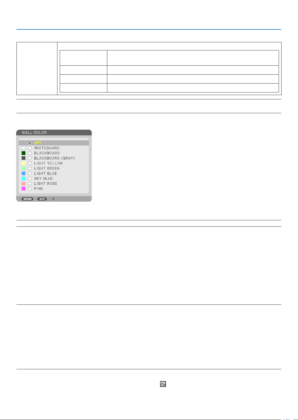
97
5. Using On-Screen Menu
Selecting Aspect Ratio and Position for Screen [SCREEN TYPE]
Screentype Setstheaspectratiooftheprojectionscreen.
FREE Theratiooftheliquidcrystalpanelisselected.Selectthiswhenprojecting
multi-screenand17:9screen(2K).
4:3screen Forascreenwitha4:3aspectratio
16:9screen Forascreenwitha16:9aspectratio
16:10screen Forascreenwitha16:10aspectratio
NOTE:
•
Afterchangingthescreentype,checkthesettingof[ASPECTRATIO]inthemenu.(→ page 80)
Using the Wall Color Correction [WALL COLOR]
Thisfunctionallowsforquickadaptivecolorcorrectioninapplicationswherethescreenmaterialisnotwhite.
NOTE:Selecting[WHITEBOARD]reduceslampbrightness.
Selecting Fan Mode [FAN MODE]
FanModeisusedtosetthespeedoftheinternalcoolingfan.
MODE �������������������� Select three modes for fan speed: AUTO, HIGH, and HIGH ALTITUDE�
AUTO: The built-in fans automatically run at a variable speed according to the internal temperature�
HIGH: The built-in fans run at high speed
HIGH ALTITUDE: The built-in fans run at a high speed� Select this option when using the projector at altitudes
approximately 5500 feet/1600 meters or higher� To use the projector with ECO MODE ON in other installed
conditions than desktop/ceiling with +/-20°, heed the following:
(1) Select [HIGH ALTITUDE] for [MODE] at altitude 3200 feet/1000 meters�
(2) Select [OFF] for [ECO MODE] at altitude 6800 feet/2100 meters or higher�
NOTE:
• Makesurethespeedissetto[HIGH]whenyouareusingthisdevicecontinuouslyforseveraldays.
•Set[FANMODE]to[HIGHALTITUDE]whenusingtheprojectorataltitudesapproximately5500feet/1600metersorhigher.
• Usingtheprojectorataltitudesapproximately5500feet/1600metersorhigherwithoutsettingto[HIGHALTITUDE]cancause
the projector to overheat and the protector could shut down. If this happens, wait a couple minutes and turn on the projector.
•Usingtheprojectorataltitudeslessthanapproximately5500feet/1600metersandsettingto[HIGHALTITUDE]cancausethe
lamptoovercool,causingtheimagetoicker.Switch[FANMODE]to[AUTO].
•Usingtheprojectorataltitudesapproximately5500feet/1600metersorhighercanshortenthelifeofopticalcomponentssuch
as the lamp.
• Yoursettingwillnotbeaffectedevenwhen[RESET]isdonefromthemenu.
TIP:
• When[HIGHALTITUDE]isselectedfor[FANMODE],asymbolicon will be displayed at the bottom of the menu.

98
5. Using On-Screen Menu
[LAMP MODE]
Wheneco-modeissetto[ON],theCO
2
emissions(calculatedfromthereductioninpowerconsumption)oftheprojec-
torcanbereduced.Theeco-modereducespowerconsumptionbymainlyloweringthebrightnessofthelamp.Asa
result,thelampreplacementtime(asaguide)*isextended.(→page118)
* Replacementtimenotguaranteed.
LAMP ADJUST ������� This can be set when the eco-mode is set to [OFF]� Adjust the lamp to match the brightness of each projector
when projecting a multi-screen display using multiple projectors�
ECOMODE OFF Thelampluminance(brightness)willbecome100%andthescreenwillturnbright.
Theluminanceofthelampcanbesetusingthelampadjustment.
ON Thelampluminance(brightness)willbecomeapproximately80%andthelampreplacementtime
(estimated)*willbeextended.
* Thereplacementtimeisnotguaranteed.
LAMPADJUST Whenthe[ECOMODE]issetto[OFF],[LAMPADJUST]isenabled.
Adjustthelamptomatchthebrightnessofeachprojectorwhenprojectingamulti-screendisplay
usingmultipleprojectors.
[REF. WHITE BALANCE]
Thisfeatureallowsyoutoadjustthewhitebalanceforallsignals.
Thewhiteandblacklevelsofthesignalareadjustedforoptimumcolorreproduction.
Uniformityisalsoadjustedwhentheredness(R)andblueness(B)ofthewhitecolorinthescreen’shorizontal(left/
right)directionareuneven.
CONTRAST R/CONTRAST G/CONTRAST B
������������������������������ These adjust the picture’s white color�
BRIGHTNESS R/BRIGHTNESS G/BRIGHTNESS B
������������������������������ These adjust the picture’s black color�
UNIFORMITY R ������ The further this is set to the + side, the stronger the redness on the left side of the picture (increasing
towards the left edge) and the weaker the redness on the right side of the picture (decreasing towards the
right edge)�
This is reversed when set to the – side�
UNIFORMITY B ������ The further this is set to the + side, the stronger the blueness on the left side of the picture (increasing
towards the left edge) and the weaker the blueness on the right side of the picture (decreasing towards the
right edge)�
This is reversed when set to the – side�
[STATICCONVERGENCE]
Thisfeaturesallowsyoutoadjustforcolordeviationinthepicture.
Thiscanbeadjustedinunitsof±1pixelinthehorizontaldirectionforHORIZONTALR,GandB,intheverticaldirec-
tionforVERTICALR,GandB.
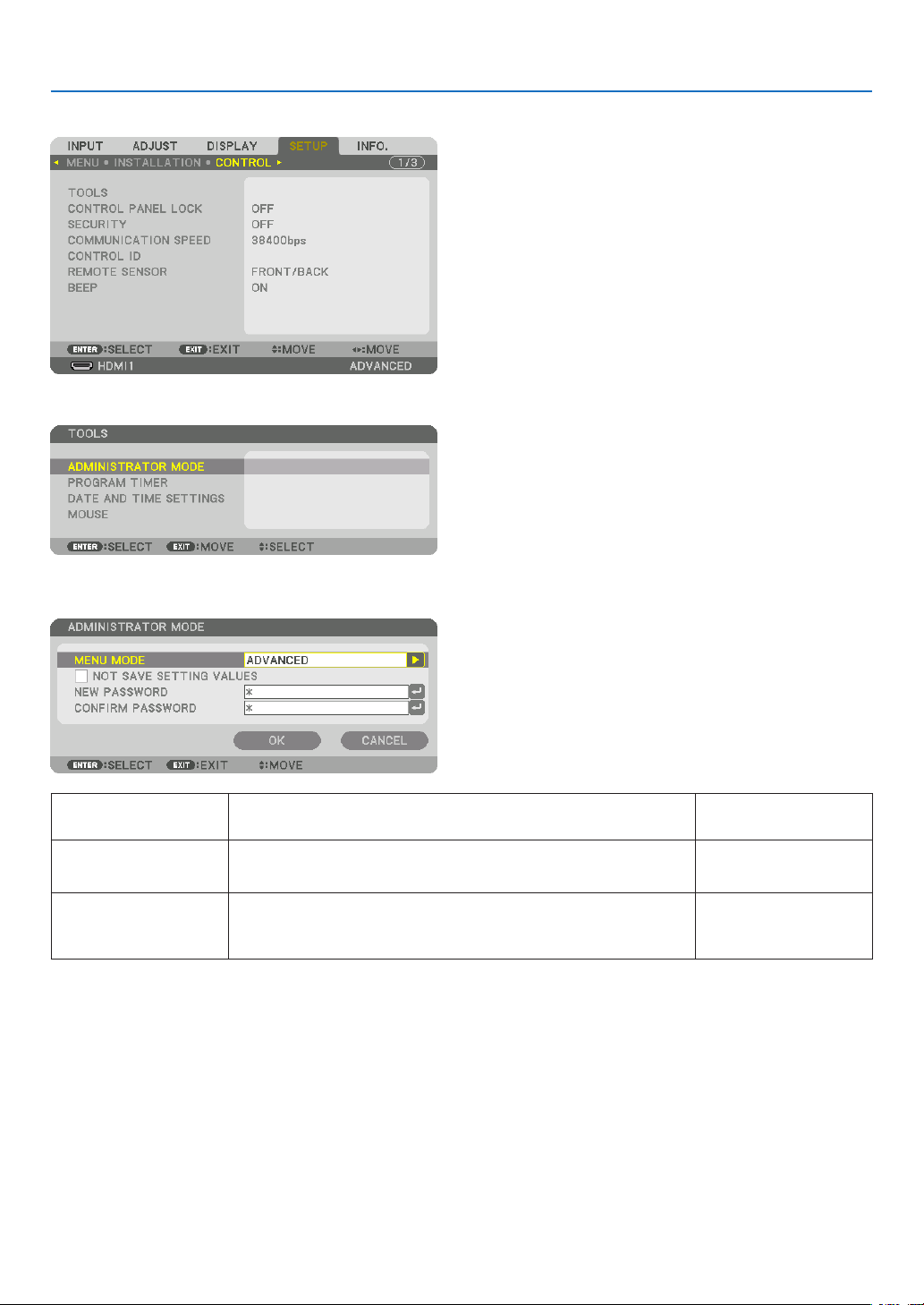
99
5. Using On-Screen Menu
[CONTROL]
TOOLS
ADMINISTRATOR MODE
ThisallowsyoutoselectMENUMODE,savesettings,andsetapasswordfortheadministratormode.
MENUMODE Selecteither[BASIC]or[ADVANCED]menu.
(→page64)
—
NOTSAVESETTING
VALUES
Placing a check mark will not save your projector settings�
Clear this check box to save your projector settings�
—
NEWPASSWORD/
CONFIRMPASS-
WORD
Assignapasswordfortheadministratormode. Upto10alphanumeric
characters
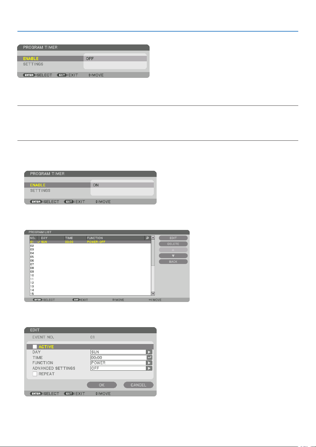
100
5. Using On-Screen Menu
PROGRAM TIMER
Thisoptionturnson/standbytheprojectorandchanges videosignals,andselectsECOmode automaticallyata
speciedtime.
NOTE:
• Beforeusing[PROGRAMTIMER],makesurethatthe[DATEANDTIME]featureisset.(→ page 103)
MakesurethattheprojectorisinthestandbyconditionwiththePOWERcordconnected.
The projector has a built-in clock. The clock will keep working for about two weeks after the main power is turned off. If the main
power is not supplied to the projector for two weeks or more, the built-in clock stops working.
Setting a new program timer
1. On the PROGRAM TIMER screen, use the ▲ or ▼buttontoselect[SETTINGS]andpresstheENTERbut-
ton.
The[PROGRAMLIST]screenwillbedisplayed.
2. Select a blank program number and press the ENTER button.
The[EDIT]screenwillbedisplayed.
3. Make settings for each item as required.
ACTIVE ������������������ Place a check mark to enable the program�
DAY ������������������������ Select days of the week for the program timer� To execute the program from Monday to Friday, select [MON-
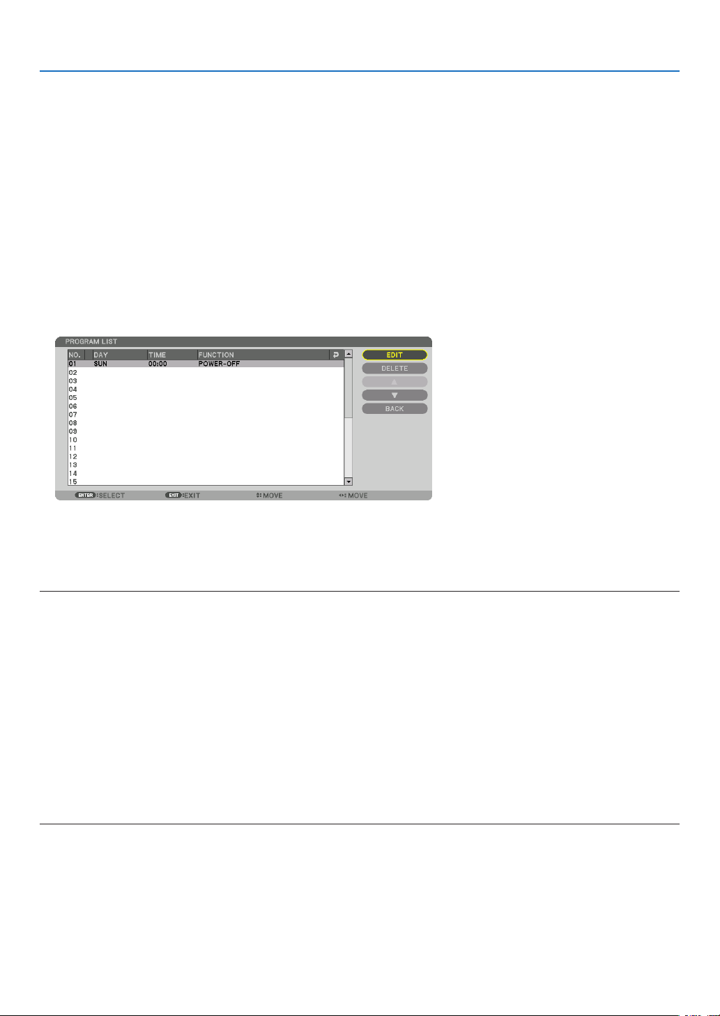
101
5. Using On-Screen Menu
FRI]� To execute the program in everyday basis, select [EVERYDAY]�
TIME ���������������������� Set the time to execute the program� Enter time in 24-hour format�
FUNCTION ������������� Select a function to be executed� Selecting [POWER] will allow you to turn on or off the projector by setting
[ADVANCED SETTINGS]� Selecting [INPUT] will allow you to select a video source by setting [ADVANCED
SETTINGS]� Selecting [ECO MODE] will allow you to select [ECO MODE] by setting [ADVANCED SET-
TINGS]�
ADVANCED SETTINGS
������������������������������ Select power on/off, a type of video source, or ECO MODE for the selected item in [FUNCTION]�
REPEAT ������������������ Place a check mark to repeat the program continuing basis� To use the program this week only, clear the
check mark�
4. Select[OK]andpresstheENTERbutton.
Thiswillcompletethesettings.
Youwillbereturnedtothe[PROGRAMLIST]screen.
5. Select[BACK]andpresstheENTERbutton.
Youwillbereturnedtothe[PROGRAMTIMER]screen.
6. Select[OK]andpresstheENTERbutton.
Youwillbereturnedtothe[TOOLS]screen.
NOTE:
• Upto30differenttimersettingscanbeprogrammed.
• When[PROGRAMTIMER]isturnedon,the[STANDBYMODE]settingisignored.
• TheProgramTimerisexecutedonasettimebasis,notinaprogrambasis.
• Oncetheprogramnotmarkedwithacheckin[REPEAT]hasbeenexecuted,thecheckmarkinthe[ACTIVE]checkboxwillbe
cleared automatically and the program will be disabled.
• Whentheon-timeandtheoff-timesetforthesametime,theoff-timesettingwilltakepreference.
• Twodifferentsourcesaresetforthesametime,thelargerprogramnumberwilltakepreference.
• Theon-timesettingwillnotbeexecutedwhilethecoolingfansarerunningoranerrorisoccurring.
• Iftheoff-timesettingisexpiredundertheconditioninwhichthepoweroffisnotpossible,theoff-timersettingwillnotbeexecuted
until the power off becomes possible.
• Programsnotmarkedwithacheckmarkin[ACTIVE]ofthe[EDIT]screenwillnotbeexecutedeveniftheProgramTimeris
enabled.
• Whentheprojectoristurnedonbyusingtheprogramtimerandifyouwanttoturnofftheprojector,settheoff-timeordoit
manually so as not to leave the projector on for a long period of time.

102
5. Using On-Screen Menu
Activating the program timer
1. Select[ENABLE]onthe[PROGRAMTIMER]screenandpresstheENTERbutton.
Theselectionscreenwillbedisplayed.
2. Press the ▼buttontoalignthecursorwith[ON]andthenpresstheENTERbutton.
Returntothe[PROGRAMTIMER]screen.
NOTE:
• Whentheeffectivesettingsofthe[PROGRAMTIMER]havenotbeensetto[ON],theprogramwillnotbeexecutedevenifthe
[ACTIVE]itemsintheprogramlisthavebeenticked.
• Evenwhentheeffectivesettingsofthe[PROGRAMTIMER]aresetto[ON],the[PROGRAMTIMER]willnotworkuntilthe[PRO-
GRAMTIMER]screenisclosed.
Changing the programmed settings
1. Onthe[PROGRAMLIST]screen,selectaprogramyouwanttoeditandpresstheENTERbutton.
2. Changethesettingsonthe[EDIT]screen.
3. Select[OK]andpresstheENTERbutton.
Theprogrammedsettingswillbechanged.
Youwillbereturnedtothe[PROGRAMLIST]screen.
Changing the order of programs
1. Onthe[PROGRAMLIST]screen,selectaprogramwhoseorderyouwanttochangeandpressthe▶ but-
ton.
2. Press the ▼ button to select ▲ or ▼.
3. Press the ENTER button a few times to select a row to which you wish to move the program.
Theorderoftheprogramswillbechanged.
Deleting the programs
1. Onthe[PROGRAMLIST]screen,selectaprogramnumberyouwanttodeleteandpressthe▶ button.
2. Press the ▼buttontoselect[DELETE].
3. Press the ENTER button.
Theconrmationscreenwillbedisplayed.
4. Select[YES]andpresstheENTERbutton.
Theprogramwillbedeleted.
Thiswillcompletedeletingtheprogram.

103
5. Using On-Screen Menu
DATE AND TIME SETTINGS
Youcansetthecurrenttime,month,date,andyear.
NOTE:Theprojectorhasabuilt-inclock.Theclockwillkeepworkingforabout2weeksafterthemainpoweristurnedoff.Ifthe
mainpowerisofffor2weeksormore,thebuilt-inclockwillcease.Ifthebuilt-inclockceases,setthedateandtimeagain.The
built-in clock will not cease while in the standby mode.
TIME ZONE SETTINGS
�������������� Select your time zone�
DATE AND TIME SETTINGS ������ Set your current date (MM/DD/YYYY) and time (HH:MM)�
INTERNET TIME SERVER ��������� If you place a check mark, the projector’s built-in clock will be synchronized with an Internet
time server in every 24 hours and at the time of projector’s startup�
UPDATE ������������������������������������ Synchronizes the projector’s built-in clock immediately� The UPDATE button is not available
unless the INTERNET TIME SERVER check box is turned on�
SUMMER TIME SETTINGS ������� If you place a check mark, the clock for daylight saving will be enabled�
[MOUSE]
Thisfunctioncannotbeusedinthisdevice.Itisusedforfutureexpansionpurposesonly.

104
5. Using On-Screen Menu
DisablingtheCabinetButtons[CONTROLPANELLOCK]
ThisoptionturnsonorofftheCONTROLPANELLOCKfunction.
NOTE:
• Howtocancelthe[CONTROLPANELLOCK]
Whenthe[CONTROLPANELLOCK]issetto[ON],presstheEXITbuttonortheINPUTbuttononthemainbodyforabout10
secondstocancelthe[CONTROLPANELLOCK]setting.
TIP:
• Whenthe[CONTROLPANELLOCK]isturnedon,akeylockicon[ ]willbedisplayedatthebottomrightofthemenu.
• ThisCONTROLPANELLOCKdoesnotaffecttheremotecontrolfunctions.
EnablingSecurity[SECURITY]
ThisfeatureturnsonorofftheSECURITYfunction.
Unlessthecorrectkeywordisentered,theprojectorcannotprojectanimage.(→page36)
NOTE:Yoursettingwillnotbeaffectedevenwhen[RESET]isdonefromthemenu.
Selecting Communication Speed [COMMUNICATION SPEED]
ThisfeaturesetsthebaudrateofthePCControlport(D-Sub9P).Itsupportsdataratesfrom4800to115200bps.
Thedefaultis38400bps.Selecttheappropriatebaudrateforyourequipmenttobeconnected(dependingonthe
equipment,alowerbaudratemayberecommendedforlongcableruns).
NOTE:
• Select[38400bps]orlesswhenusingthesuppliedsoftwareprograms.
• Yourselectedcommunicationspeedwillnotbeaffectedevenwhen[RESET]isdonefromthemenu.
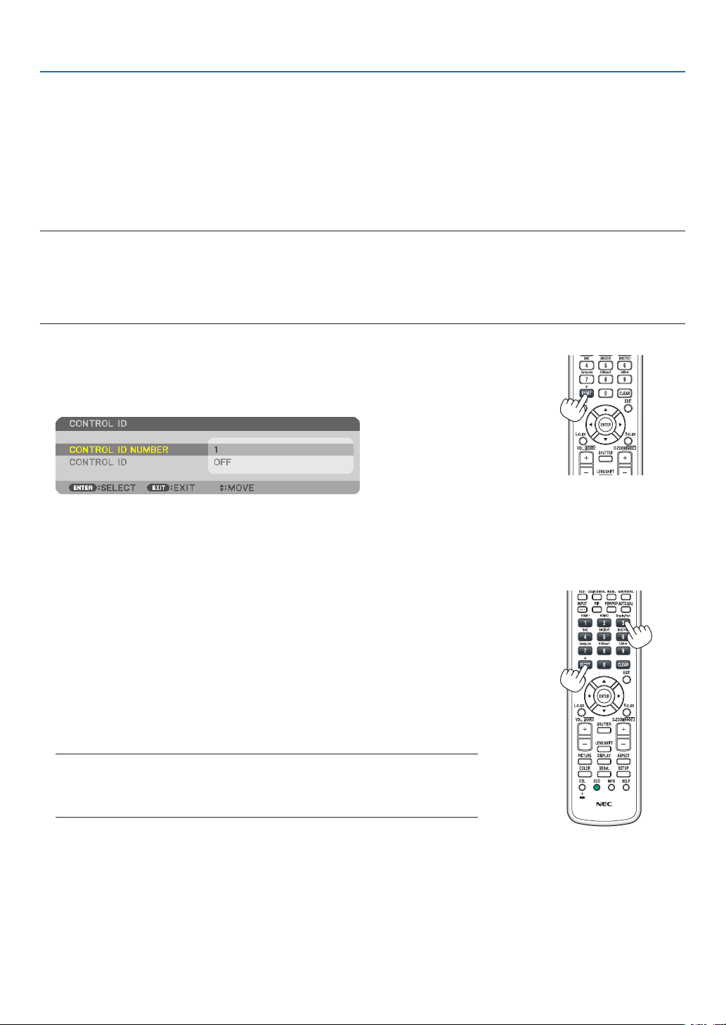
105
5. Using On-Screen Menu
Setting ID to the Projector [CONTROL ID]
YoucanoperatemultipleprojectorsseparatelyandindependentlywiththesingleremotecontrolthathastheCONTROL
IDfunction.IfyouassignthesameIDtoalltheprojectors,youcanconvenientlyoperatealltheprojectorstogether
usingthesingleremotecontrol.Todoso,youhavetoassignanIDnumbertoeachprojector.
CONTROL ID NUMBER �������Select a number from 1 to 254 you wish to assign to your projector�
CONTROL ID �����������������������Select [OFF] to turn off the CONTROL ID setting and select [ON] to turn on the CONTROL ID set-
ting�
NOTE:
• When[ON]isselectedfor[CONTROLID],theprojectorcannotbeoperatedbyusingtheremotecontrolthatdoesnotsupport
theCONTROLIDfunction.(Inthiscasethebuttonsontheprojectorcabinetcanbeused.)
• Yoursettingwillnotbeaffectedevenwhen[RESET]isdonefromthemenu.
•PressingandholdingtheENTERbuttonontheprojectorcabinetfor10secondswilldisplaythemenuforcancelingtheControl
ID.
Assigning or Changing the Control ID
1. Turn on the projector.
2. Press the ID SET button on the remote control.
TheCONTROLIDscreenwillbedisplayed.
IftheprojectorcanbeoperatedwiththecurrentremotecontrolID,the[AC-
TIVE]willbedisplayed.Iftheprojectorcannotbeoperatedwiththecurrent
remotecontrolID,the[INACTIVE]willbedisplayed.Tooperatetheinactive
projector,assignthecontrolIDusedfortheprojectorbyusingthefollowing
procedure(Step3).
3. Press one of numeric keypad buttons while pressing and holding the ID
SET button on the remote control.
Example:
Toassign“3”,pressthe“3”buttonontheremotecontrol.
NoIDmeansthatalltheprojectorscanbeoperatedtogetherwithasingle
remotecontrol.Toset“NoID”,enter“000”orpresstheCLEARbutton.
TIP:TherangeofIDsisfrom1to254.
4. Release the ID SET button.
TheupdatedCONTROLIDscreenwillbedisplayed.
NOTE:
•TheIDscanbeclearedinafewdaysafterthebatteriesarerundownorremoved.
•Accidentallypressinganyoneofthebuttonsoftheremotecontrolwillclearcurrently
speciedIDwithbatteriesremoved.

106
5. Using On-Screen Menu
Turning On or Off Remote Sensor [REMOTE SENSOR]
Thisoptiondetermineswhichremotesensorontheprojectorisenabledinwirelessmode.
Theoptionsare:FRONT/BACK,FRONT,BACK,andHDBaseT.
NOTE:
• TheremotecontroloftheprojectorwillnotbeabletoreceivesignalsifthepowersupplyoftheHDBaseTtransmissiondevice
connectedtotheprojectorisswitchedonwhenthishasbeensetto“HDBaseT”.
TIP:
• Iftheremotecontrolsystemdoesnotfunctionwhendirectsunlightorstrongilluminationstrikestheremotecontrolsensorof
the projector, change another option.
EnablingKeySoundandErrorSound[BEEP]
Thisfeatureturns on or off the buttonsoundoralarm when an error occurs or the followingoperationsare per-
formed.
• Displayingthemainmenu
• Switchingsources
• Resettingdatabyusing[RESET]
• PressingPOWERONorSTANDBYbutton

107
5. Using On-Screen Menu
[NETWORK SETTINGS]
Important:
• Consultwithyournetworkadministratoraboutthesesettings.
• WhenusingawiredLANconnection,connectaLANcable(Ethernetcable)totheLANport(RJ-45)oftheprojector.(→ page
137)
TIP:Thenetworksettingsyoumakewillnotbeaffectedevenwhen[RESET]isdonefromthemenu.
Hints on How to Set Up LAN Connection
To set up the projector for a LAN connection:
Select[WIREDLAN]→[PROFILES]→[PROFILE1]or[PROFILE2].
TwosettingscanbesetforwiredLAN.
Nextturnonorofffor[DHCP],[IPADDRESS],[SUBNETMASK],and[GATEWAY]andselect[OK]andpressthe
ENTERbutton.(→page108)
TorecallLANsettingsstoredintheprolenumber:
Select[PROFILE1]or[PROFILE2]forwiredLAN,andthenselect[OK]andpresstheENTERbutton.(→page
108)
To connect a DHCP server:
Turnon[DHCP]forwiredLAN.Select[ON]andpresstheENTERbutton.TospecifyIPaddresswithoutusingthe
DHCPserver,turnoff[DHCP].(→page108)
To receive lamp replacement time or error messages via e-mail:
Select[ALERTMAIL],andset[SENDER'SADDRESS],[SMTPSERVERNAME],and[RECIPIENT'SADDRESS].
Last,select[OK]andpresstheENTERbutton.(→page110)

108
5. Using On-Screen Menu
WIRED LAN
PROFILES • Thesettingsfor using the built-inEthernet/HDBaseT port in
theprojectorcanberecordedintheprojectormemoryintwo
ways.
• Select[PROFILE1]or[PROFILE2]andthendosettingsfor
[DHCP]andtheotheroptions.
Afterdoingthis,select[OK]andpresstheENTERbutton.This
willstoreyoursettingsinmemory.
• Torecallthesettingsfrommemory:
Afterselecting[PROFILE1]or[PROFILE2]fromthe[PRO-
FILES]list.
Select[OK]andpresstheENTERbutton.
• Select[DISABLE]whennotconnectingtoawiredLAN
—
DHCP
PlaceacheckmarktoautomaticallyassignanIPaddresstothe
projectorfromyourDHCPserver.
ClearthischeckboxtoregistertheIPaddressorsubnetmask
numberobtainedfromyournetworkadministrator.
—
IPADDRESS SetyourIPaddressofthenetworkconnectedtotheprojector
when[DHCP]isturnedoff.
Upto12numeric
characters
SUBNETMASK Setyoursubnetmasknumberofthenetworkconnectedtothe
projectorwhen[DHCP]isturnedoff.
Upto12numeric
characters
GATEWAY
Setthedefaultgatewayofthenetworkconnectedtotheprojector
when[DHCP]isturnedoff.
Upto12numeric
characters
AUTODNS PlaceacheckmarktoautomaticallyassigntheIPaddressofyour
DNSserverconnectedtotheprojectorfromyourDHCPserver.
ClearthischeckboxtosettheIPaddressofyourDNSserver
connectedtotheprojector.
Upto12numeric
characters
DNSCONFIGURA-
TION
SettheIPaddressofyourDNSserveronthenetworkconnected
totheprojectorwhen[AUTODNS]iscleared.
Upto12numeric
characters
RECONNECT
Retrytoconnecttheprojectortoanetwork.Trythisifyouhave
changed[PROFILES].
—
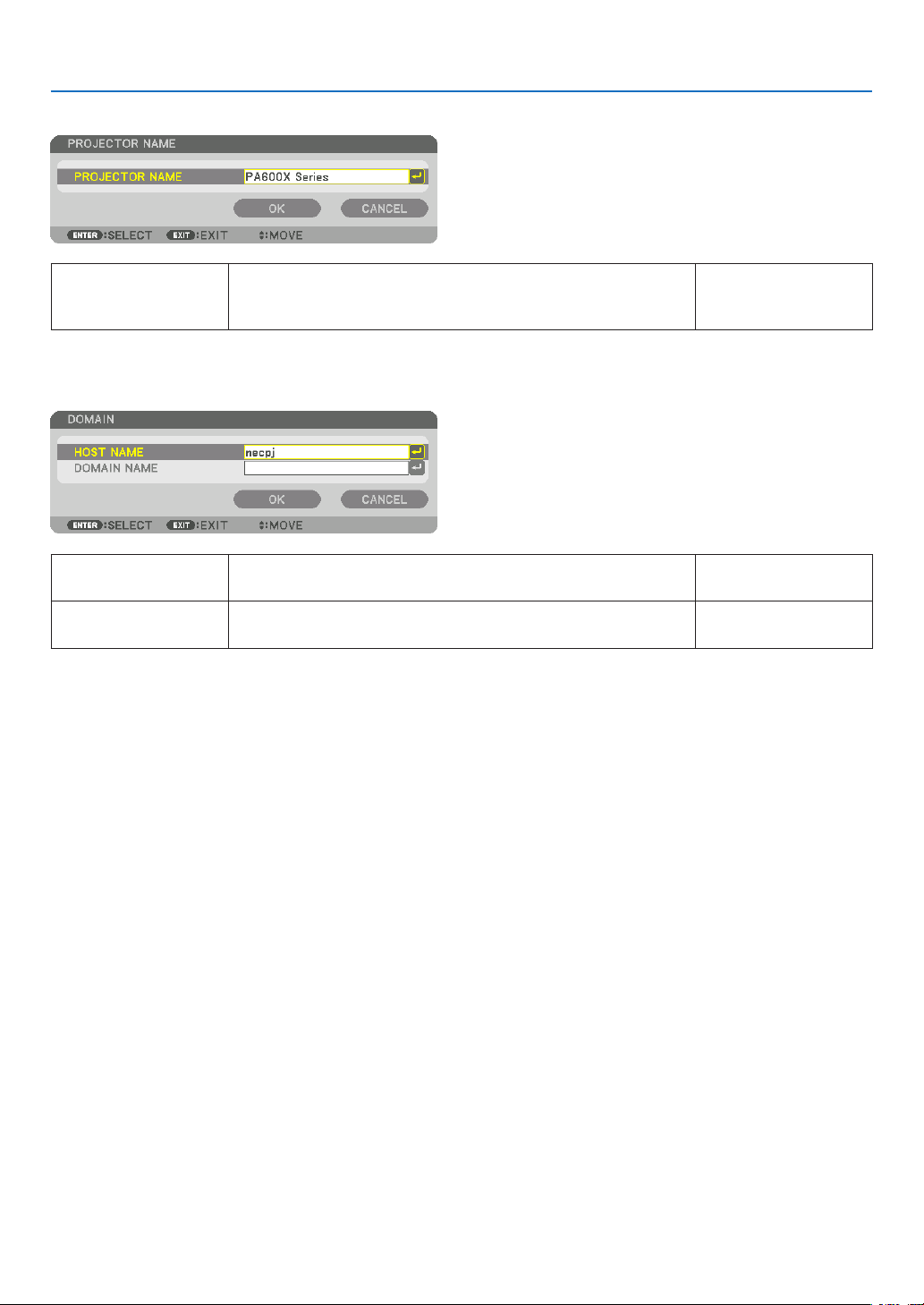
109
5. Using On-Screen Menu
PROJECTOR NAME
PROJECTORNAME Setauniqueprojectorname. Upto16alphanu-
mericcharactersand
symbols
DOMAIN
Setahostnameanddomainnameoftheprojector.
HOSTNAME Setahostnameoftheprojector. Upto15alphanumeric
characters
DOMAINNAME Setadomainnameoftheprojector. Upto60alphanumeric
characters
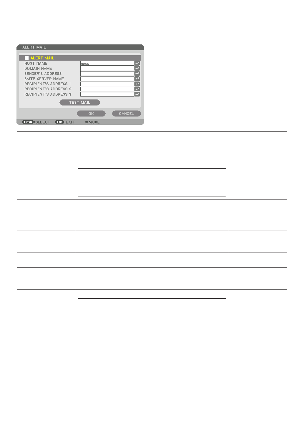
110
5. Using On-Screen Menu
ALERT MAIL
ALERTMAIL Thisoptionwillnotifyyourcomputeroflampreplacetimeorerror
messagesviae-mailwhenusingwirelessorwiredLAN.
Placing a checkmark will turn on the Alert Mail feature�
Clearing a checkmark will turn off the Alert Mail feature�
Sample of a message to be sent from the projector:
Thelampandltersareattheendofitsusablelife.Please
replacethelampandlters.
ProjectorName:NECProjector
LampHoursUsed:100[H]
—
HOSTNAME Typeinahostname. Upto15alphanumeric
characters
DOMAINNAME Typeinadomainnameofthenetworkconnectedtotheprojec-
tor.
Upto60alphanumeric
characters
SENDER'SAD-
DRESS
Specifythesender’saddress. Upto60alphanu-
mericcharactersand
symbols
SMTPSERVER
NAME
TypeintheSMTPservernametobeconnectedtotheprojec-
tor.
Upto60alphanumeric
characters
RECIPIENT'SAD-
DRESS1,2,3
Typeinyourrecipient’saddress. Upto60alphanu-
mericcharactersand
symbols
TESTMAIL Sendatestmailtocheckifyoursettingsarecorrect.
NOTE:
• Ifyouenteredanincorrectaddressinatest,youmaynotreceivean
Alert mail. Should this happen, check if the Recipient’s Address is
correctly set.
• Unless any one of the [SENDER'S ADDRESS], [SMTP SERVER'S
NAME]or[RECIPIENT'SADDRESS1-3]isselected,[TESTMAIL]is
not available.
• Besuretohighlight[OK]andpresstheENTERbuttonbeforeexecuting
[TESTMAIL].
—

111
5. Using On-Screen Menu
NETWORKSERVICE
HTTPSERVER SetapasswordforyourHTTPserver. Upto10alphanumeric
characters
PJLink
This option allows you to set a password when you use the
PJLinkfeature.
NOTE:
• Donotforgetyourpassword.However,ifyouforgetyourpassword,
consult with your dealer.
• WhatisPJLink?
PJLinkisastandardizationofprotocolusedforcontrollingprojectors
of different manufacturers. This standard protocol is established by
JapanBusinessMachineandInformationSystemIndustriesAssocia-
tion(JBMIA)in2005.
TheprojectorsupportsallthecommandsofPJLinkClass1.
• SettingofPJLinkwillnotbeaffectedevenwhen[RESET]isdonefrom
the menu.
Upto32alphanumeric
characters
AMXBEACON Turnon orofffordetection fromAMXDeviceDiscoverywhen
connectingtothenetworksupportedbyAMX’sNetLinxcontrol
system.
TIP:
WhenusingadevicethatsupportsAMXDeviceDiscovery,allAMXNetLinx
control system will recognize the device and download the appropriate
DeviceDiscoveryModulefromanAMXserver.
Placing a checkmark will enable detecting the projector from AMX Device
Discovery�
Clearing a checkmark will disable detecting the projector from AMX
Device Discovery�
—

112
5. Using On-Screen Menu
[SOURCE OPTIONS]
Setting Auto Adjust [AUTO ADJUST]
ThisfeaturesetstheAutoAdjustmodesothatthecomputersignalcanbeautomaticallyormanuallyadjustedfor
noiseandstability.Youcanautomaticallymakeadjustmentintwoways:[NORMAL]and[FINE].
OFF ������������������������ The computer signal will not be automatically adjusted� You can manually optimize the computer signal�
NORMAL ���������������� Default setting� The computer signal will be automatically adjusted� Normally select this option�
FINE ����������������������� Select this option if fine adjustment is needed� It takes more time to switch to the source than when [NOR-
MAL]is selected�
TIP:
• Thedefaultsettingwhenshippedfromthefactoryis[NORMAL].
• WhentheAUTOADJ.buttonispressed,thesame[FINE]adjustmentiscarriedout.
[COLOR SYSTEM]
ThisfeatureallowsyoutoselecttheTVvideosignal,whichdiffersfromcountrytocountry(NTSC,PAL,etc.).
Thisissetto[AUTO]byfactorydefault.Setthisiftheprojectorcannotidentifythesignalautomatically.
[AUDIO SELECT]
ThisselectstheaudioinputoftheHDMI1INterminal,HDMI2INterminal,DisplayPortinputterminalandEthernet/
HDBaseTport.
Wheninputtinganalogaudio,connecttheaudiooutputterminaloftheconnectingdevicewiththeBNCaudioinput
terminalandsettheAudioSelectto“BNC”.
Selecting Default Source [DEFAULT INPUT SELECT]
Youcansettheprojectortodefaulttoanyoneofitsinputseachtimetheprojectoristurnedon.
LAST ���������������������� Sets the projector to default to the previous or last active input each time the projector is turned on�
AUTO ��������������������� Searches for an active source in order of HDMI1 → HDMI2 → DisplayPort → BNC → BNC(CV) → BNC(Y/C)
→ COMPUTER →
HDBaseT and displays the first found source�
HDMI1 ������������������� Displays the digital source from the HDMI 1 IN connector every time the projector is turned on�
HDMI2 ������������������� Displays the digital source from the HDMI 2 IN connector every time the projector is turned on�
DisplayPort ������������ Displays the digital source from the DisplayPort every time the projector is turned on�
BNC ����������������������� Project the input signal from the BNC video input terminal
BNC(CV)
���������������� Project the input signal from the BNC(CV) video input terminal�
BNC(Y/C) ��������������� Project the input signal from the BNC(Y/C) video input terminal�
COMPUTER ����������� Displays the computer signal from the COMPUTER IN connector every time the projector is turned on�
HDBaseT ���������������� Project the HDBaseT signal�

113
5. Using On-Screen Menu
[SEAMLESS SWITCHING]
Whentheinputconnectorisswitched,theimagedisplayedbeforeswitchingisheldtoswitchtothenewimagewithout
abreakduetoabsenceofasignal.
Setting Closed Caption [CLOSED CAPTION]
ThisoptionsetsseveralclosedcaptionmodesthatallowtexttobesuperimposedontheprojectedimageofVideo
orS-Video.
Thesubtitlesandtextwillbedisplayedashortwhileaftertheon-screenmenudisappears.
OFF ������������������������ This exits the closed caption mode�
CAPTION 1-4 ��������� Text is superimposed�
TEXT 1-4 ���������������� Text is displayed�
SelectingaColororLogoforBackground[BACKGROUND]
Use this feature to display a blue/black screen or logo when no signal is available.The default background is
[BLUE].
NOTE:
• Evenwhenthebackgroundlogoisselected,iftwopicturesaredisplayedin[PIP/PICTUREBYPICTURE]mode,thebluebackground
is displayed without the logo when there is no signal.

114
5. Using On-Screen Menu
[POWER OPTIONS]
Selecting Power-saving in [STANDBY MODE]
Settingthepowerconsumptioninthestandbymode.
NORMAL ���������������� In the standby mode, the power consumption of the projector is 0�11 W (100-130 V)/0�16 W (200-
240 V)�
In the standby mode, the POWER indicator lights up in red while the STATUS indicator will go off�
• Whensetto[NORMAL],thefollowingterminalsandfunctionswillbedisabled.HDMIoutputterminals,
audio output terminals, Ethernet/HDBaseT port, USB-A port, LAN function, mail notification function
HDBaseT STANDBY
������������������������������ Compared to [NORMAL], the power consumption in the standby mode is higher but power can be supplied
to the projector using a wired LAN�
In the standby mode, the power indicator will light up in orange while the status indicator will be turned
off�
Important:
• When[HDBaseTSTANDBY]isselected,[AUTOPOWEROFF]willturngreyincolorandbedisabledand[0:15]willbeselected
automatically.
• Inthefollowingconditions,the[STANDBYMODE]settingwillbedisabledandtheprojectorwillgointothesleepmode.
* Sleepmodereferstothemodewherebythefunctionalrestrictionsduetothe[STANDBYMODE]settingareremoved.
• When[ENABLE]isselectedunder[NETWORKSERVICE]→[AMXBEACON]
• When[HDBaseT]isselectedunder[CONTROL]→[REMOTESENSOR]
• WhenasignalisbeingreceivedfromaHDBaseTtransmissiondevice
• When[NORMAL]isselected,the[AUTOPOWERONSELECT]displayturnsgreyincolorandisdisabled,and[OFF]isautomati-
cally selected.
NOTE:
• WhenconnectingtoaHDBaseTtransmissiondevicesoldcommercially,ifthetransmissiondeviceissettotransmitremotecontrol
signals, the power consumption of the projector in the standby mode will increase.
TIP:
• Yoursettingwillnotbeaffectedevenwhen[RESET]isdonefromthemenu.
• ThepowerconsumptioninthestandbymodewillnotbeincludedincalculatingCO
2
emission reduction.
Enabling Direct Power On [DIRECT POWER ON]
Turnstheprojectoronautomaticallywhenthepowercordisinsertedintoanactivepoweroutlet.Thiseliminatesthe
needtoalwaysusethePOWERbuttonontheremotecontrolorprojectorcabinet.

115
5. Using On-Screen Menu
TurningOntheProjectorByApplyingComputerSignal[AUTOPOWERONSELECT]
Thissettingautomaticallyprojectsanycomputersignalthatisinputwhentheprojectorisinthestandbymode.
Connecttotheinputterminalontheprojectorusingacableandputtheprojectorinthestandbymode.
Whenusingthe[AUTOPOWERONSELECT],setthe[STANDBYMODE]to[HDBaseTSTANDBY],turnonthepower
supplyofthetransmissiondeviceandkeepitinaconnectedstate.
OFF ������������������������ AUTO POWER ON SELECT function will be switch off�
HDMI1, HDMI2, DisplayPort, COMPUTER, HDBaseT
������������������������������ When a computer signal of a selected input terminal is detected, the power supply of the projector will be
turned on automatically and the computer screen will be projected�
NOTE:
• ThisfunctionwillnotworkforcomputersignalssuchasSynconGreenorCompositeSyncandwhencomponentsignalsare
inputtothecomputerorBNCvideoinputterminal.
• IfyouwanttotesttheAUTOPOWERONSELECTafterswitchingoffthepowersupplyoftheprojector,waitforthreeormore
secondsrstafterswitchingoffthepowerbeforeinputtinganycomputersignal.Whenthepowersupplyisswitchedoffandthe
projector goes into the standby mode, the projector will continue to remain in the standby mode without power supply being
restored if a computer signal continues to be input to the projector.
Enabling Power Management [AUTO POWER OFF]
Whenthisoptionisselectedyoucanenabletheprojectortoautomaticallyturnoff(attheselectedtime:0:05,0:10,
0:15,0:20,0:30,1:00)ifthereisnosignalreceivedbyanyinputorifnooperationisperformed.
NOTE:
• ThepowerwillnotgooffautomaticallywhenasignalfromtheEthernet/HDBaseTportisbeingprojected.
• [AUTOPOWEROFF]appearsingreywhenthe[STANDBYMODE]issetto[HDBaseTSTANDBY]and[0:15]willbesetautomati-
cally.
Using Off Timer [OFF TIMER]
1. Select your desired time between 30 minutes and 16 hours: OFF, 0:30, 1:00, 2:00, 4:00, 8:00, 12:00, 16:00.
2. Press the ENTER button on the remote control.
3. The remaining time starts counting down.
4. The projector will turn off after the countdown is complete.
NOTE:
• Tocancelthepresettime,set[OFF]forthepresettimeorturnoffthepower.
• Whentheremainingtimereaches3minutesbeforetheprojectoristurnedoff,the[THEPROJECTORWILLTURNOFFWITHIN3
MINUTES]messagewillbedisplayedonthebottomofthescreen.
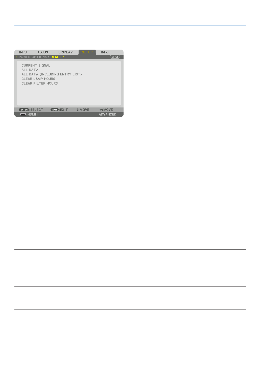
116
5. Using On-Screen Menu
Returning to Factory Default [RESET]
TheRESETfeatureallowsyoutochangeadjustmentsandsettingstothefactorypresetfora(all)source(s)except
thefollowing:
[CURRENT SIGNAL]
Resetstheadjustmentsforthecurrentsignaltothefactorypresetlevels.
Theitemsthatcanberesetare:[PRESET],[CONTRAST],[BRIGHTNESS],[COLOR],[HUE],[SHARPNESS],[AS-
PECTRATIO],[HORIZONTAL],[VERTICAL],[CLOCK],[PHASE],and[OVERSCAN].
[ALL DATA]
Resetalltheadjustmentsandsettingsforallthesignalstothefactorypreset.
AllitemscanberesetEXCEPT[LANGUAGE],[BACKGROUND],[FILTERMESSAGE],[EDGEBLENDING],[MULTI
SCREEN],[SCREENTYPE],[GEOMETRICCORRECTION],[REF.WHITEBALANCE],[STATICCONVERGENCE],
[ADMINISTRATOR MODE], [CONTROL PANEL LOCK], [SECURITY], [COMMUNICATION SPEED], [CONTROL
ID],[STANDBYMODE],[FANMODE],[LAMPLIFEREMAINING],[LAMPHOURSUSED],[FILTERHOURSUSED],
[TOTALCARBONSAVINGS],and[WIREDLAN].
Toresetthelampusagetime,see“ClearingLampHourMeter[CLEARLAMPHOURS]”below.
[ALLDATA(INCLUDINGENTRYLIST)]
Resetalltheadjustmentsandsettingsforallthesignalstothefactorypresetexcept[LANGUAGE],[BACKGROUND],
[FILTERMESSAGE],[EDGEBLENDING],[MULTISCREEN],[SCREENTYPE],[GEOMETRICCORRECTION],[REF.
WHITEBALANCE],[STATICCONVERGENCE],[ADMINISTRATORMODE],[CONTROLPANELLOCK],[SECURITY],
[COMMUNICATIONSPEED],[CONTROLID],[STANDBYMODE],[FANMODE],[LAMPLIFEREMAINING],[LAMP
HOURSUSED],[FILTERHOURSUSED],[TOTALCARBONSAVINGS],and[WIREDLAN].
Alsodeletesallthesignalsinthe[ENTRYLIST]andreturnstothefactorypreset.
NOTE:LockedsignalsinEntryListcannotbereset.
Clearing Lamp Hour Meter [CLEAR LAMP HOURS]
Resetsthelampclockbacktozero.Selectingthisoptiondisplayssubmenuforaconrmation.Select[YES]andpress
theENTERbutton.
NOTE:
• Elapsedtimeofthelampusewillnotbeaffectedevenwhen[RESET]isdonefromthemenu.
• Performing[CLEARLAMPHOURS]willreturnthe[LAMPADJUST]in[LAMPMODE]toitsdefaultadjustments.Whentheprojec-
torisusedformulti-screenprojection,use[LAMPADJUST]toadjustthebrightnessagain.

117
5. Using On-Screen Menu
Clearing the Filter Usage Hours [CLEAR FILTER HOURS]
Resetsthelterusagebacktozero.Selectingthisoptiondisplayssubmenuforaconrmation.Select[YES]andpress
theENTERbutton.
The[OFF]itemisselectedfor[FILTERMESSAGE]atthetimeofshipment.When[OFF]isselected,youdonotneed
toclearthelterusagehour.
NOTE:Elapsedtimeofthelterusewillnotbeaffectedevenwhen[RESET]isdonefromthemenu.
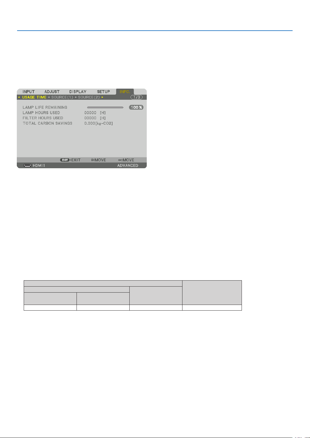
118
5. Using On-Screen Menu
❽ Menu Descriptions & Functions [INFO.]
Displaysthestatusofthecurrentsignalandlampusage.Thisitemhasninepages.Theinformationincludedisas
follows:
TIP:PressingtheHELPbuttonontheremotecontrolwillshowthe[INFO.]menuitems.
[USAGE TIME]
[LAMPLIFEREMAINING](%)*
[LAMPHOURSUSED](H)
[FILTERHOURSUSED](H)
[TOTALCARBONSAVINGS](kg-CO2)
* Theprogressindicatorshowsthepercentageofremainingbulblife.
Thevalueinformsyouoftheamountoflampusage.Whentheremaininglamptimereaches0,theLAMPLIFE
REMAININGbarindicatorchangesfrom0%to100Hoursandstartscountingdown.
Iftheremaininglamptimereaches0hours,theprojectorwillnotturnon.
• Themessagetotheeffectthatthelamportheltersshouldbereplacedwillbedisplayedforoneminutewhen
theprojectoristurnedonandwhenthePOWERbuttonontheprojectorortheremotecontrolispressed.
Todismissthismessage,pressanybuttonontheprojectorortheremotecontrol.
Lamplife(H)
Replacement lamp
ECO MODE
During portrait
installation
NORMAL
(OFF)
ECO
(ON)
3000 4000 2000 NP26LP
• [TOTALCARBONSAVINGS]
Thisdisplaystheestimatedcarbonsavinginformationinkg.Thecarbonfootprintfactorinthecarbonsavingcal-
culationisbasedontheOECD(2008Edition).(→page30)
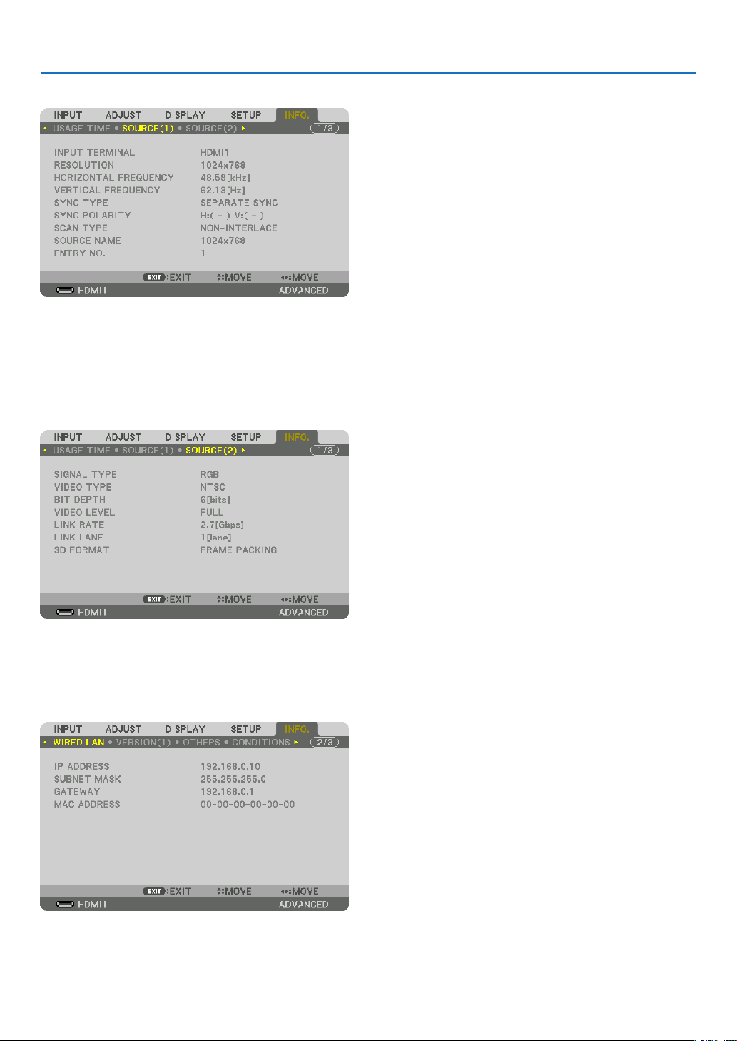
119
5. Using On-Screen Menu
[SOURCE(1)]
INPUTTERMINAL RESOLUTION
HORIZONTALFREQUENCY VERTICAL FREQUENCY
SYNCTYPE SYNC POLARITY
SCANTYPE SOURCE NAME
ENTRYNO.
[SOURCE(2)]
SIGNALTYPE VIDEOTYPE
BITDEPTH VIDEO LEVEL
LINKRATE LINKLANE
[WIRED LAN]
IPADDRESS SUBNETMASK
GATEWAY MACADDRESS
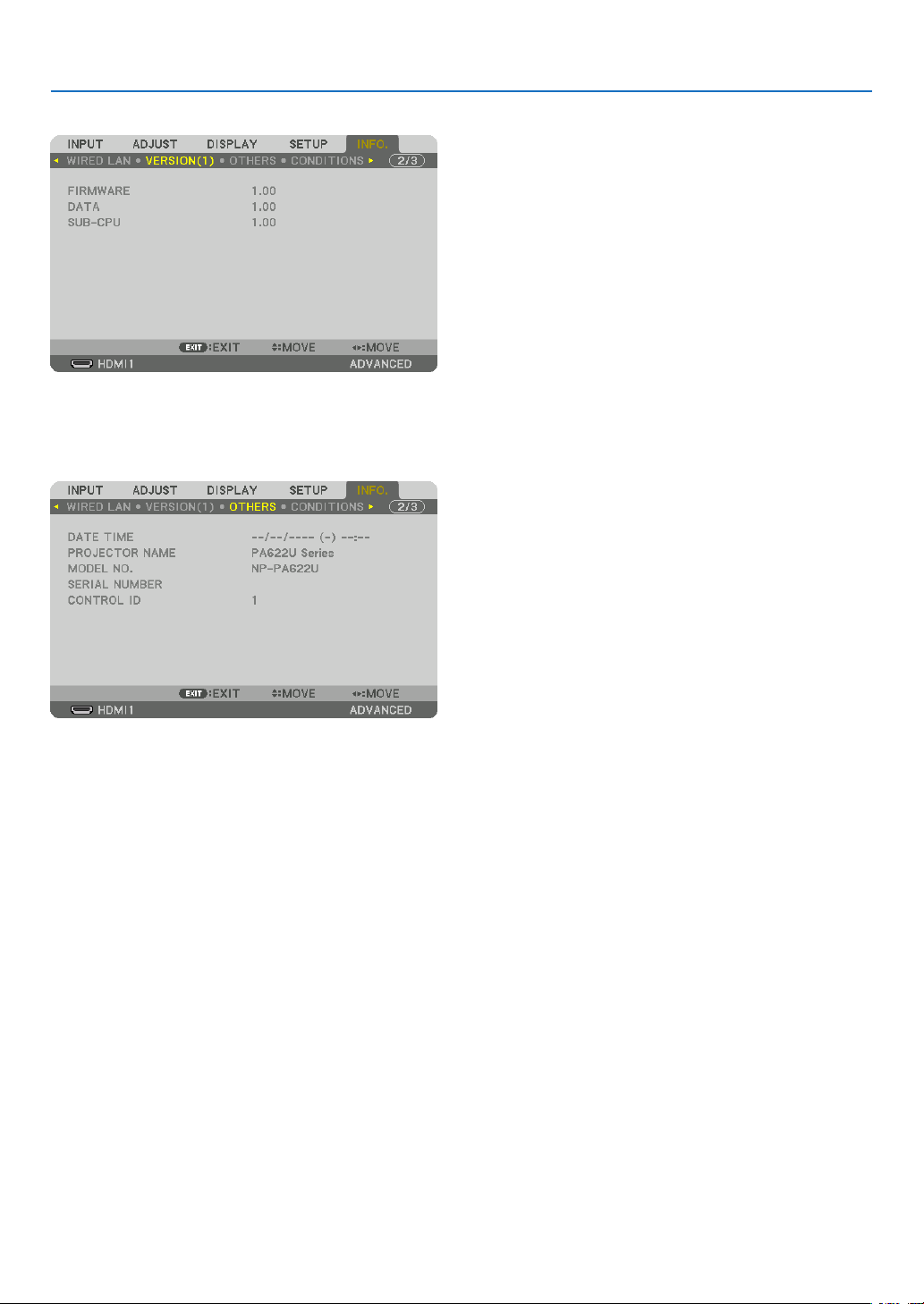
120
5. Using On-Screen Menu
[VERSION(1)]
FIRMWARE DATA
SUB-CPU
[OTHERS]
DATETIME PROJECTORNAME
MODELNO. SERIAL NUMBER
CONTROLID(when[CONTROLID]isset)
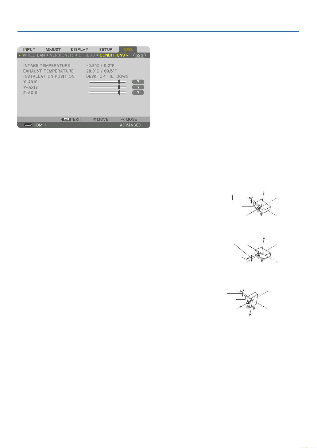
121
5. Using On-Screen Menu
[CONDITIONS]
INTAKETEMPERATURE EXHAUSTTEMPERATURE
INSTALLATIONPOSITION X-AXIS
Y-AXIS Z-AXIS
AbouttheX-AXIS,Y-AXISandZ-AXISCONDITIONS
* ArrowdirectionoftheZ-AXISinthegurerepresentsthetopoftheprojector.
X-AXIS ������������������� Display the projector image at an angle of −100 – +100
degrees to the horizontal in the X-axis direction�
X-AXISvalueof
theprojector
Horizontalplane
X-axis
Gravitydirection
Y-AXIS ������������������� Display the projector image at an angle of −100 – +100
degrees to the horizontal in the Y-axis direction�
Y-AXISvalueof
theprojector
Horizontalplane
Y-axis
Gravitydirection
Z-AXIS ������������������� Display the projector image at an angle of −100 – +100
degrees to the vertical in the Z-axis direction�
Z-AXISvalueof
theprojector
Horizontal
planeZ-axis
Gravitydirection

122
5. Using On-Screen Menu
[HDBaseT]
SIGNALQUALITY OPERATIONMODE
LINKSTATUS HDMISTATUS
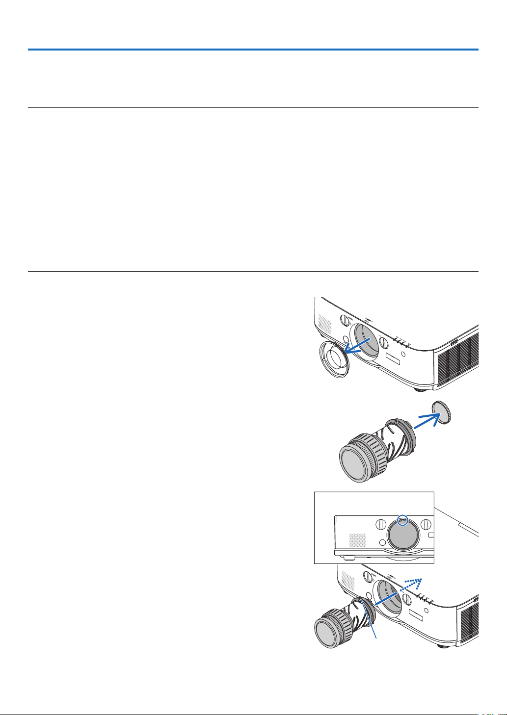
123
❶ Mounting a lens (sold separately)
Sixseparatebayonetstylelensescanbeusedwiththisprojector.ThedescriptionsherearefortheNP13ZL(2xzoom)
lens.Mountotherlensesinthesamemanner.
NOTE:
• Theprojectorandlensesaremadeofprecisionparts.Donotsubjectthemtoshockorexcessiveforces.
• Removetheseparatelysoldlenswhenmovingtheprojector.Ifnot,thelenscouldbesubjecttoshockwhiletheprojectorisbeing
moved, damaging the lens and the lens shift mechanism.
• Turnoffthepowerandwaitforthecoolingfantostopbeforemountingorremovingthelens.
• Nevertouchthelenssurfacewhiletheprojectorisoperating.
• Beverycarefulnottoletdirt,grease,etc.,onthelenssurfaceandnottoscratchthelenssurface.
• Performtheseoperationsonaatsurfaceoverapieceofcloth,etc.,topreventthelensfromgettingscratched.
• Whenleavingthelensofftheprojectorforlongperiodsoftime,mountthedustcapontheprojectortopreventdustordirtfrom
getting inside.
• Ifyouhavemultipleprojectors,becarefulofthefollowing:
- WhenmountingalensdesignedexclusivelyforthisprojectorontoanotherprojectorintheNPseries,besuretoremovethe
lensattachmentbeforemountingthelensontheprojector.Thelenscannotbemountedifitsattachmentison.Forthetypes
oflensesthatcanbemountedandinstructionsonremovingthem,seethelense’soperatinginstructions.
- Other types of lenses cannot be mounted on this projector.
Mounting the lens
1. Remove the dust cap from the projector.
2. Remove the lens cap on the back of the lens.
3. Insert the lens onto the projector with the yellow-marked
protrusion on the lens facing upwards.
Thereisapositioningslitontheprojector’slensinsertionslot.
Insertthelensslowlyallthewayin,keepingthepositioningslit
atthesameangle.
Guidingnotch
Yellowmark
6. Connecting to Other Equipment
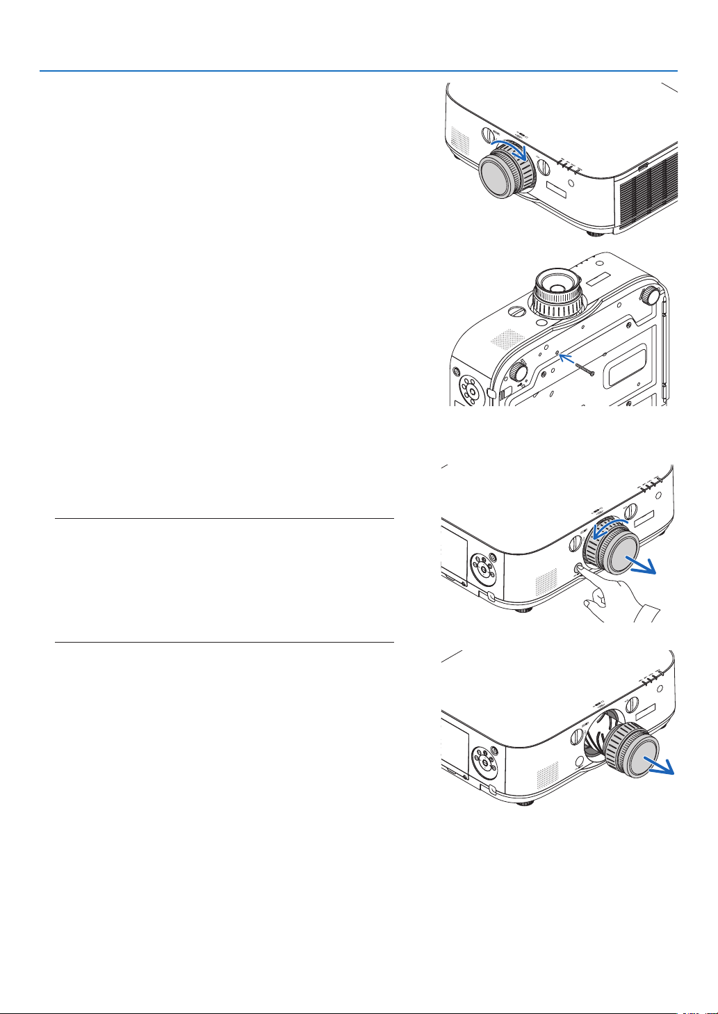
124
6. Installation and Connections
4. Turn the lens clockwise.
Turnuntilaclickisheard.
Thelensisnowfastenedontotheprojector.
TIP:Mountingthelenstheftpreventionscrew
Fastenthelenstheftpreventionscrewincludedwiththeprojectortothe
bottom of the projector so that the lens cannot be removed easily.
Removing the lens
1. While pressing the lens release button on the projector’s
front panel fully in, turn the lens counterclockwise.
Thelenscomesoff.
NOTE:
• Checkthefollowingareasifthelensunitcannotberemovedeven
when the lens release button is pressed.
1.Checkwhetherthetheftpreventionscrewsofthelensunithave
been installed.
2.Thelensreleasebuttonmaybelockedsometimes.Inthatcase,
turn the lens fully to the right. The lens release button lock will
be released.
2. Slowly pull the lens off the projector.
• Afterremovingthelens,mountthelenscaps(frontandback)
includedwiththelensbeforestoringthelens.
• Ifnolensisgoingtobemountedontheprojector,mountthe
dustcapincludedwiththeprojector.
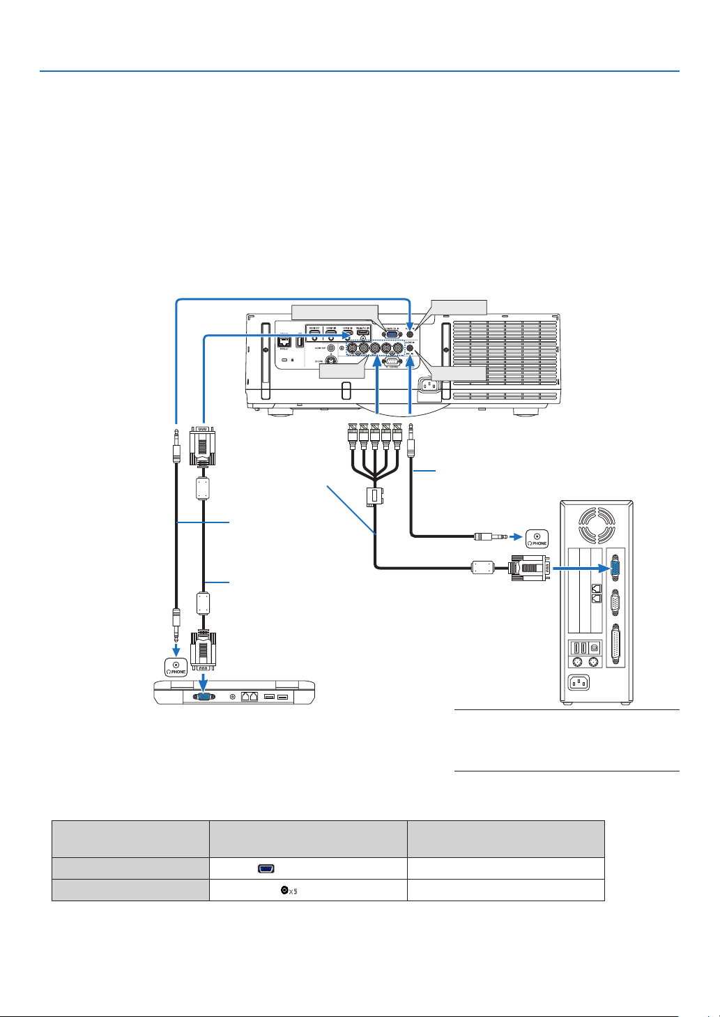
125
6. Installation and Connections
❷ Making Connections
Acomputercable,BNCcable(5-coretype),HDMIcable,oraDisplayPortcablecanbeusedtoconnecttoacom-
puter.
Theconnectioncableisnotenclosedwiththeprojector.Pleasegetreadyasuitablecablefortheconnection.
Analog RGB signal connection
• Connectthecomputercabletothedisplayoutputterminal(miniD-sub15pin)onthecomputerandthecomputer
videoinputterminalontheprojector.Pleaseuseacomputercableattachedwithaferritecore.
• Whenconnectingthedisplayoutputterminal(miniD-sub15pin)onthecomputertotheBNCvideoinputterminal,
useaconversioncabletoconverttheBNCcable(5core)toaminiD-sub15pincable.
• Selectthesourcenameforitsappropriateinputconnectorafterturningontheprojector.
Inputconnector
INPUTbuttonontheprojector
cabinet
Buttonontheremotecontrol
COMPUTERIN 7:COMPUTER 7/COMPUTER
BNCIN 4:BNC 4/BNC
COMPUTER IN
BNC IN
AUDIO IN
AUDIO IN
Computercable(soldcommercially)
Stereomini-plugaudio
cable(notsupplied)
RGB-to-BNCcable
(notsupplied)
Stereomini-plugaudiocable(notsupplied)
NOTE: Please check the operating manual of
the computer as the name, position and direc-
tion of the terminal may differ depending on
the computer.
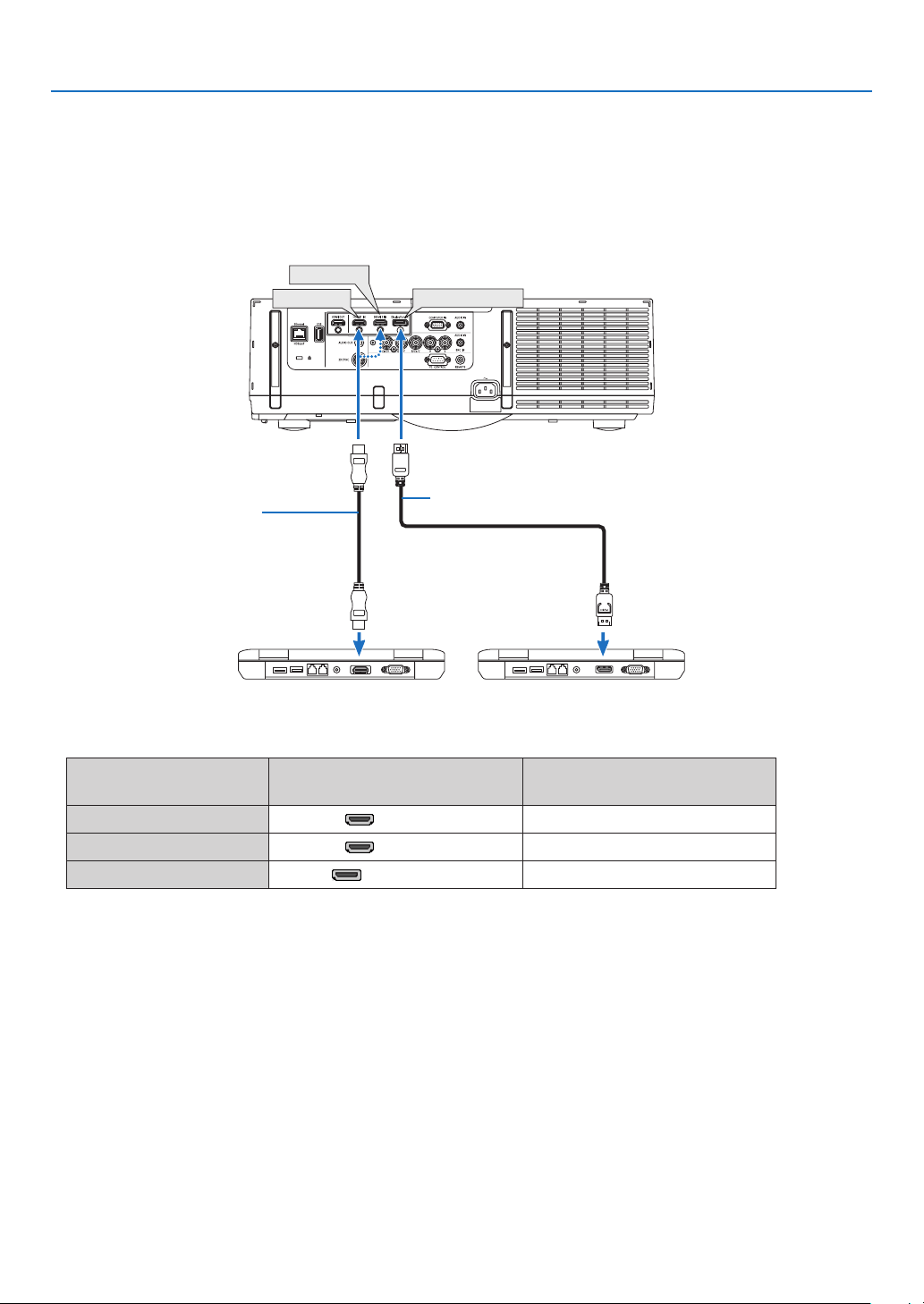
126
6. Installation and Connections
Digital RGB signal connection
• ConnectacommerciallyavailableHDMIcablebetweenthecomputer’sHDMIoutputconnectorandtheprojector’s
HDMI1orHDMI2inputconnector.
• ConnectacommerciallyavailableDisplayPortcablebetweenthecomputer’sDisplayPortoutputconnectorand
theprojector’sDisplayPortinputconnector.
• Selectthesourcenameforitsappropriateinputconnectorafterturningontheprojector.
Inputconnector
INPUTbuttonontheprojector
cabinet
Buttonontheremotecontrol
HDMI1IN 1:HDMI1 1/HDMI1
HDMI2IN 2:HDMI2 2/HDMI2
DisplayPortIN 3:DisplayPort 3/DisplayPort
DisplayPort IN
HDMI 1 IN
HDMI 2 IN
HDMIcable(notsupplied)
DisplayPortcable(notsupplied)

127
6. Installation and Connections
Cautions when connecting an HDMI cable
• UseacertiedHighSpeedHDMI
®
CableorHighSpeedHDMI
®
CablewithEthernet.
CautionswhenconnectingaDisplayPortcable
• UseacertiedDisplayPortcable.
• Dependingonthecomputer,sometimemayberequireduntiltheimageisdisplayed.
• SomeDisplayPortcables(commerciallyavailable)havelocks.
• Todisconnectthecable,pressthebuttononthetopofthecable’sconnector,thenpullthecableout.
• PowercanbesuppliedtotheconnectingdevicefromtheDisplayPortinputterminal(maximumof1.65W).How-
ever,powerwillnotbesuppliedtothecomputer.
• WhensignalsfromadevicethatusesasignalconverteradapterareconnectedtotheDisplayPortinputconnector,
insomecasestheimagemaynotbedisplayed.
• WhentheHDMIoutputofacomputerisconnectedtotheDisplayPortinputconnector,useaconverter(commer-
ciallyavailable).
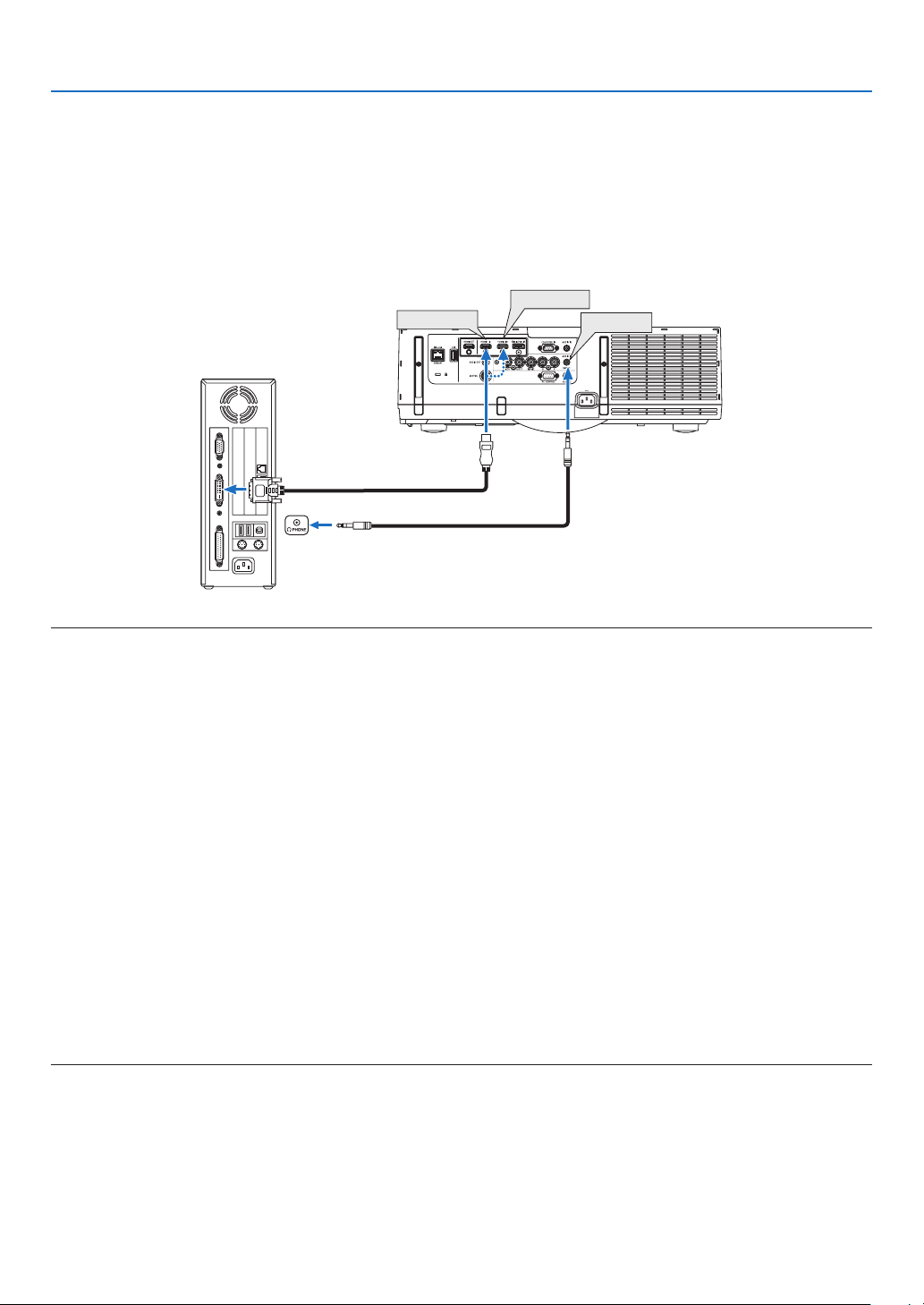
128
6. Installation and Connections
CautionswhenusingaDVIsignal
• WhenthecomputerhasaDVIoutputconnector,useacommerciallyavailableconvertercabletoconnectthe
computertotheprojector’sHDMI1orHDMI2inputconnector(onlydigitalvideosignalscanbeinput).Also,con-
nectthecomputer’saudiooutputtotheprojector’sBNCaudioinputconnector.Inthiscase,switchtheHDMI1or
HDMI2settingaton-screenmenu’saudioselectionontheprojectorto[BNC].(→page112)
Toconnectthecomputer’sDVIoutputconnectortotheprojector’sDisplayPortinputconnector,useacommercially
availableconverter.
HDMI 1 IN
HDMI 2 IN
AUDIO IN
NOTE:WhenViewingaDVIDigitalSignal
• Turnoffthepowerofthecomputerandprojectorbeforeconnecting.
• Lowerthecomputer’svolumesettingbeforeconnectinganaudiocabletotheheadphonesconnector.Whenusingwithacomputer
connected to the projector, adjust the volume of both the projector and computer to set the appropriate volume level.
• Ifthecomputerhasamini-jacktypeaudiooutputconnector,werecommendconnectingtheaudiocabletothatconnector.
• Whenavideodeckisconnectedviaascanconverter,etc.,thedisplaymaynotbecorrectduringfast-forwardingandrewind-
ing.
• UseaDVI-to-HDMIcablecompliantwithDDWG(DigitalDisplayWorkingGroup)DVI(DigitalVisualInterface)revision1.0stan-
dard.Thecableshouldbewithin197"/5mlong.
• TurnofftheprojectorandthePCbeforeconnectingtheDVI-to-HDMIcable.
• ToprojectaDVIdigitalsignal:Connectthecables,turntheprojectoron,thenselecttheHDMIinput.Finally,turnonyourPC.
Failuretodosomaynotactivatethedigitaloutputofthegraphicscardresultinginnopicturebeingdisplayed.Shouldthishappen,
restartyourPC.
• SomegraphicscardshavebothanalogRGB(15-pinD-Sub)andDVI(orDFP)outputs.Useofthe15-pinD-Subconnectormay
result in no picture being displayed from the digital output of the graphics card.
• DonotdisconnecttheDVI-to-HDMIcablewhiletheprojectorisrunning.Ifthesignalcablehasbeendisconnectedandthen
reconnected,animagemaynotbecorrectlydisplayed.Shouldthishappen,restartyourPC.
• TheCOMPUTERvideoinputconnectorssupportWindowsPlugandPlay.TheBNCvideoinputconnectordoesnotsupportWin-
dows Plug and Play.
• AMacsignaladapter(commerciallyavailable)mayberequiredtoconnectaMaccomputer.
ToconnectaMaccomputerequippedwithaMiniDisplayPorttotheprojector,useacommerciallyavailableMiniDisplayPort→
DisplayPortconvertercable.
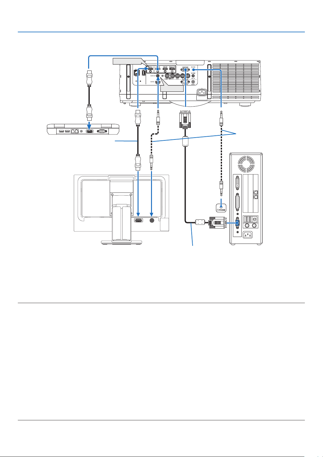
129
6. Installation and Connections
HDMI IN
AUDIO IN
HDMI OUT
AUDIO OUT
Connecting an External Monitor
Youcanconnectaseparate,externalmonitortoyourprojectortosimultaneouslyviewonamonitorthecomputer
analogimageyou’reprojecting.
• BNC(CV)componentvideosignalsandBNC(Y/C)S-videosignalswillnotbeoutput.
• PleaserefertoPage85whendisplayingthePIP/PBPscreen.
NOTE:
• WhenoutputtingHDMIsignals,turnonthepowerofthevideodeviceontheoutputsideandkeepitconnectedbeforeinputting
videosignalsintothisdevice.TheHDMIoutputterminalsoftheprojectorareequippedwithrepeaterfunctions.Whenadeviceis
connectedtotheHDMIoutputterminal,theresolutionoftheoutputsignalislimitedbytheresolutionsupportedbytheconnected
device.
• Whenthe[STANDBYMODE]ofthisdeviceissetto[NORMAL],HDMIsignalswillnotbeoutput.TooutputHDMIsignals,setthe
[STANDBYMODE]to[HDBaseTSTANDBY],turnonthepowersupplyofthetransmissiondeviceandkeepitconnected.
• InthecaseoftheHDMIoutputterminaloftheprojector,thetheoreticalnumberofunitsthatcanbeconnectedinaseriesisseven.
The maximum number of units that can be connected may be reduced by the external environment and quality of the signal and
cable,etc.ThenumberofunitsthatcanbeconnectedmaydifferdependingontheHDCPversion,restrictiononthenumberof
HDCPrepeatersinthesourcedeviceandthequalityofthecable.Theoverallsystemneedstobecheckedinadvancewhenbuild-
ing a system.
• Whenaudioequipmentisconnected,theprojectorspeakerisdisabled.
• Tooutputaudiofromtheaudiooutputterminalwhentheinputterminalisneither“COMPUTERIN”nor“BNCIN”,select[BNC]
under[AUDIOSELECT]oftheon-screenmenu.
• Whenthe[STANDBYMODE]issetto[NORMAL],videoandaudiowillnotbeoutputiftheprojectorgoesintothestandbymode.
Setthemodeto[HDBaseTSTANDBY],turnonthepowerofthetransmissiondeviceandkeepitinaconnectedstate.
Computercable(VGA)(notsupplied)
Stereomini-plugaudiocable
(notsupplied)
HDMIcable(notsupplied)
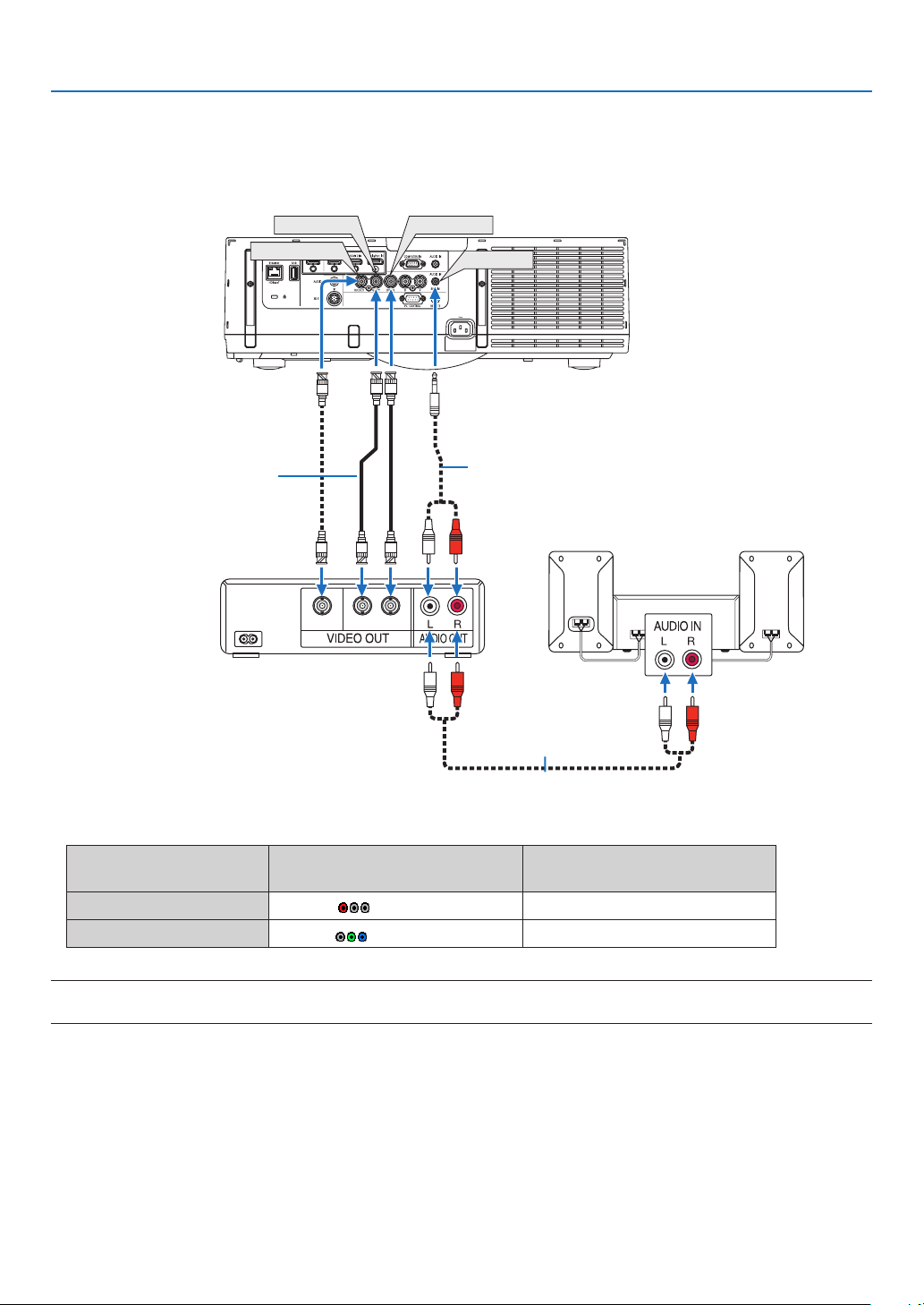
130
6. Installation and Connections
Connecting Your Blu-ray Player or Other AV Equipment
Componentvideosignal/S-videosignalconnection
• Selectthesourcenameforitsappropriateinputconnectorafterturningontheprojector.
Inputconnector
INPUTbuttonontheprojector
cabinet
Buttonontheremotecontrol
BNC(CV)IN 5:BNC(CV) 5/BNC(CV)
BNC(Y/C)IN 6:BNC(Y/C) 6/BNC(Y/C)
NOTE:
• TheBNC(analogRGB/component),BNC(CV)andBNC(Y/C)audioinputterminalsareshared.
CV YC
BNC
(
C
)
IN
AUDIO IN
BNC
(
CV
)
IN
BNC
(
Y
)
IN
Audiocable(notsupplied)
BNCcable(notsupplied)
Audioequipment
Audiocable(notsupplied)
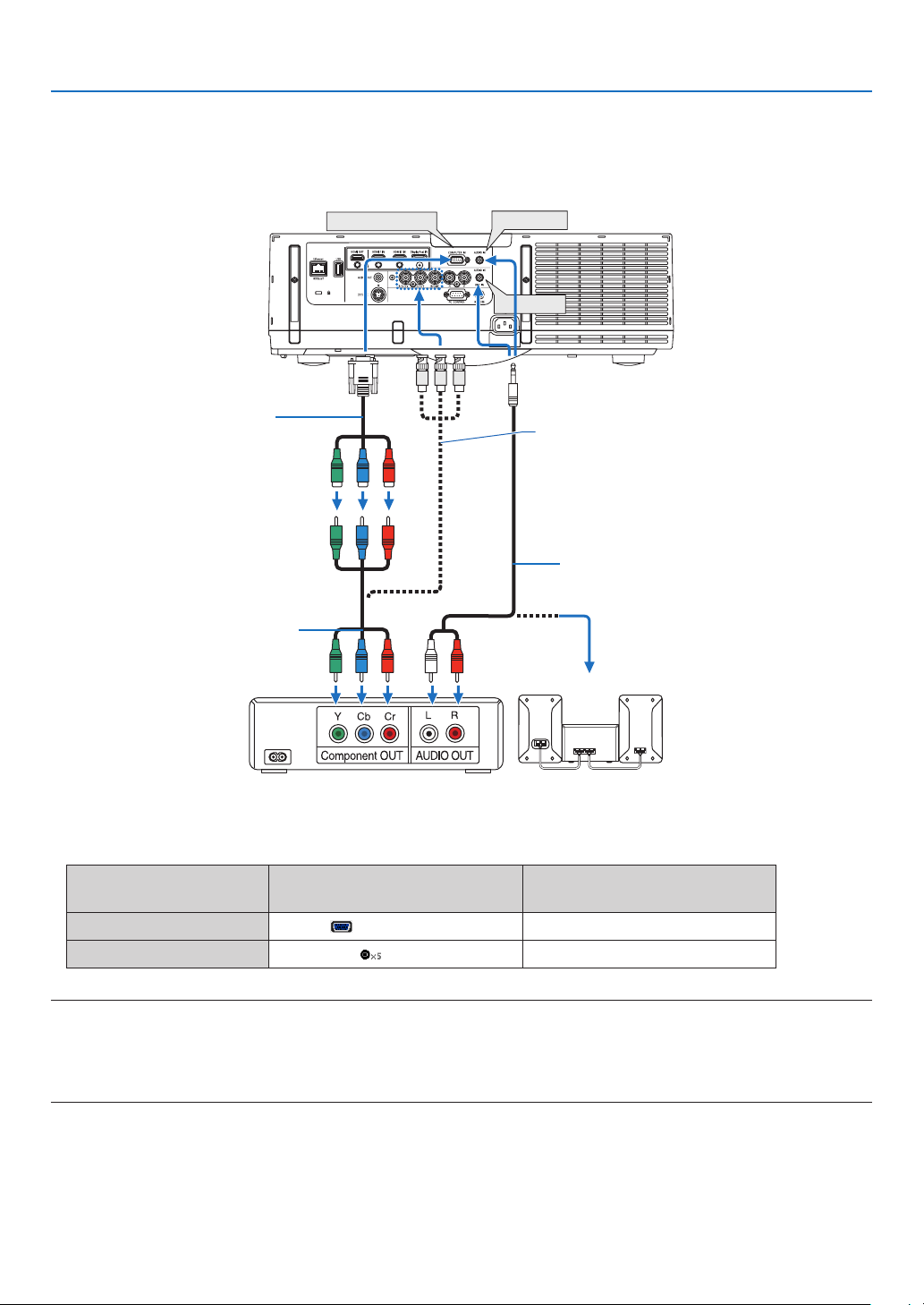
131
6. Installation and Connections
Connecting Component Input
• Selectthesourcenameforitsappropriateinputconnectorafterturningontheprojector.
Inputconnector
INPUTbuttonontheprojector
cabinet
Buttonontheremotecontrol
COMPUTERIN 7:COMPUTER 7/COMPUTER
BNCIN 4:BNC 4/BNC
NOTE:
• Whenthesignalformatissetto[AUTO](defaultfactorysettingwhenshipped),thecomputersignalandcomponentsignalare
automaticallydistinguished and switched. Ifthe signals cannot be distinguished, select [COMPONENT] under [ADJUST]→
[VIDEO]→[SIGNALTYPE]intheon-screenmenuoftheprojector.
• ToconnecttoavideodevicewithaDconnector,usethesoldseparatelyDconnectorconverteradapter(modelADP-DT1E).
AUDIO IN
COMPUTER IN
AUDIO IN
15-pin-to-RCA(female)×3
cableadapter(ADP-CV1E)
BNC(male)-to-RCA(male)conversioncable×3
(soldcommercially)
Stereominiplug-to-RCAaudiocable(not
supplied)
ComponentvideoRCA×3cable(not
supplied)
Blu-rayplayer AudioEquipment
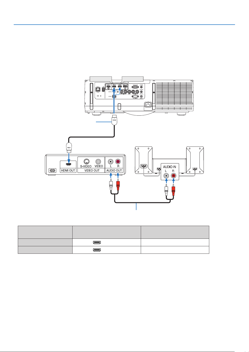
132
6. Installation and Connections
Connecting HDMI Input
YoucanconnecttheHDMIoutputofyourBlu-rayplayer,harddiskplayer,ornotebooktypePCtotheHDMI1INor
HDMI2INconnectorofyourprojector.
Inputconnector
INPUTbuttonontheprojector
cabinet
Buttonontheremotecontrol
HDMI1IN 1:HDMI1 1/HDMI1
HDMI2IN 2:HDMI2 2/HDMI2
TIP:ForusersofaudiovideoequipmentwithanHDMIconnector:
Select“Enhanced”ratherthan“Normal”ifHDMIoutputisswitchablebetween“Enhanced”and“Normal”.
This will provide improved image contrast and more detailed dark areas.
Formoreinformationonsettings,refertotheinstructionmanualoftheaudiovideoequipmenttobeconnected.
• WhenconnectingtheHDMI1INorHDMI2INconnectoroftheprojectortotheBlu-rayplayer,theprojector’svideo
levelcanbemadesettingsinaccordancewiththeBlu-rayplayer’svideolevel.Inthemenuselect[ADJUST]→
[VIDEO]→[VIDEOLEVEL]andmakenecessarysettings.
• IftheHDMIinputsoundcannotbeheard,inthemenuselect[AUDIOSELECT]→[HDMI1]or[HDMI2].
• IftheHDMI input’ssound is notoutput,checkthat[SOURCE OPTIONS] →[AUDIOSELECT]→[HDMI1] or
[HDMI2]ontheprojector’son-screenmenuissetto“HDMI”.(→page112)
HDMI 1 IN
HDMI 2 IN
Audiocable(notsupplied)
HDMIcable(notsupplied)
UseHighSpeedHDMI
®
Cable.
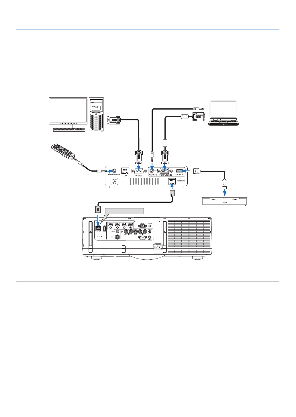
133
6. Installation and Connections
Connecting to a HDBaseT transmission device (sold commercially)
HDBaseTisaconnectionstandardforhomeappliancesthatisestablishedbytheHDBaseTAlliance.
UseaLANcablesoldcommerciallytoconnecttheEthernet/HDBaseTportoftheprojector(RJ-45)toaHDBaseT
transmissiondevicesoldcommercially.
TheEthernet/HDBaseTportoftheprojectorsupportsHDMIsignals(HDCP)fromtransmissiondevices,controlsignals
fromexternaldevices(serial,LAN)andremotecontrolsignals(IRcommands).
Connection example
Ethernet/HDBaseT
Computer(forcontroluse)
Computer(foroutputuse)
Exampleofatransmissiondevice
Ourcompany’sremote
control(PX750U/PH1000U/
PH1400USeries)
HDMIoutputvideodevice
NOTE:
• Pleaseuseashieldedtwistedpair(STP)cableofCategory5eorhigherfortheLANcable(soldcommercially).
• ThemaximumtransmissiondistanceovertheLANcableis100m.(themaximumdistanceis70mfora4Ksignal)
• Pleasedonotuseothertransmissionequipmentbetweentheprojectorandtransmissionequipment.Thepicturequalitymaybe
degraded as a result.
• ThisprojectorisnotguaranteedtoworkwithallHDBaseTtransmissiondevicessoldcommercially.
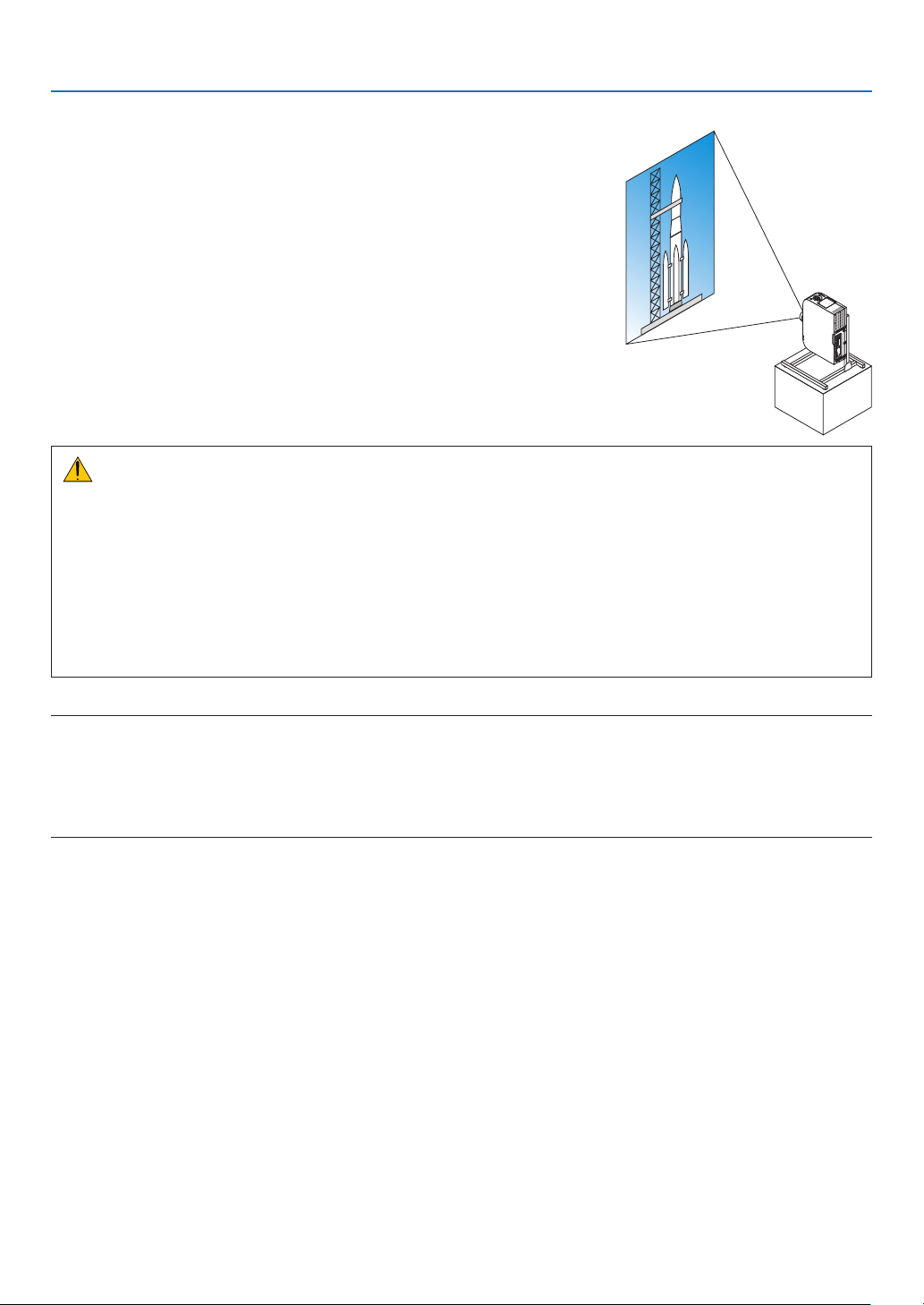
134
6. Installation and Connections
Portrait projection (vertical orientation)
Portraitscreensfromacomputercanbeprojectedbyinstallingtheprojec-
torinaverticalorientation.Allthescreenssuchastheon-screenmenu
willberotatedinancounter-clockwisedirection.
Theprojectorisequippedwithasensortoautomaticallydetecttheinstal-
lationstate.
Whentheprojectorisinstalledinaportraitcongurationforthersttime
withthelamplitup,acautionmessagetoindicatethattheoperatingtime
ofthelampmaybeshortenedwillbedisplayed.
Thismessagewillautomaticallydisappearwhentheinstallationstateof
theprojectorisreturnedtotheoriginalstate.
Precautions during installation
• Pleasedonotinstalltheprojectorinaverticalorientationontopoftheoorortableonitsown.Theairinletmay
beobstructed,resultingintheprojectorgettingwarmandthepossibilityofreandmalfunctionoccurring.
• Forverticalinstallation,installtheprojectorwiththeairinlet(lter)facingdownwards.Astandforsupporting
theprojectorneedstobemadeforthispurpose.Inthiscase,thestandmustbedesignedsuchthatthecenter
ofgravityoftheprojectorislocatedwellwithinthelegsofthestand.Ifnot,theprojectormayfalloverandresult
ininjury,damageandmalfunction.
• Donotusethelensshiftfunctionwhenperformingportraitprojection.Usethepositionofthelensshiftmecha-
nisminthecenter(lenscenter).
NOTE:
• Thelampreplacementtime(asaguide)*isabout2000hoursforportraitprojection.
* Replacementtimeisnotguaranteed.
• Wheninstallinginaportraitcongurationforthersttime,portraitprojectioncannotbeusedwhenthenumberoflamphours
usedshownunder[INFO.]→[USAGETIME]→[LAMPHOURSUSED]intheon-screenmenuexceeds1900hours.
• Whenthe[FANMODE]issettoamodeotherthan[AUTO],portraitprojectioncannotbeused.
Design and manufacturing conditions for the stand
Pleaseengageaninstallationserviceproviderforthedesignandmanufactureofthecustomizedstandtobeusedfor
portraitprojection.Pleaseensurethatthefollowingarecompliedwithwhendesigningthestand.
1. Maintainanopeningofatleast310×170mmsoasnottoobstructtheairinlet/lteroftheprojector.
2. Maintainadistanceofatleast130mmbetweentheprojectorairinletandtheoor(fortheopeningofthelter
cover).
3. Usethefourscrewholesatthebackoftheprojectortosecureittothestand.
Screwholecenterdimension:200×250mm
Screwholedimensionontheprojector:M4withamaximumdepthof8mm.
* Pleasedesignthestandsuchthattherearlegsatthebackoftheprojectordonotcontactthestand.Thefront
legscanbeturnedandremoved.
4. Horizontaladjustmentmechanism(forexample,boltsandnutsinfourlocations)
5. Pleasedesignthestandsuchthatitdoesnottoppleovereasily.
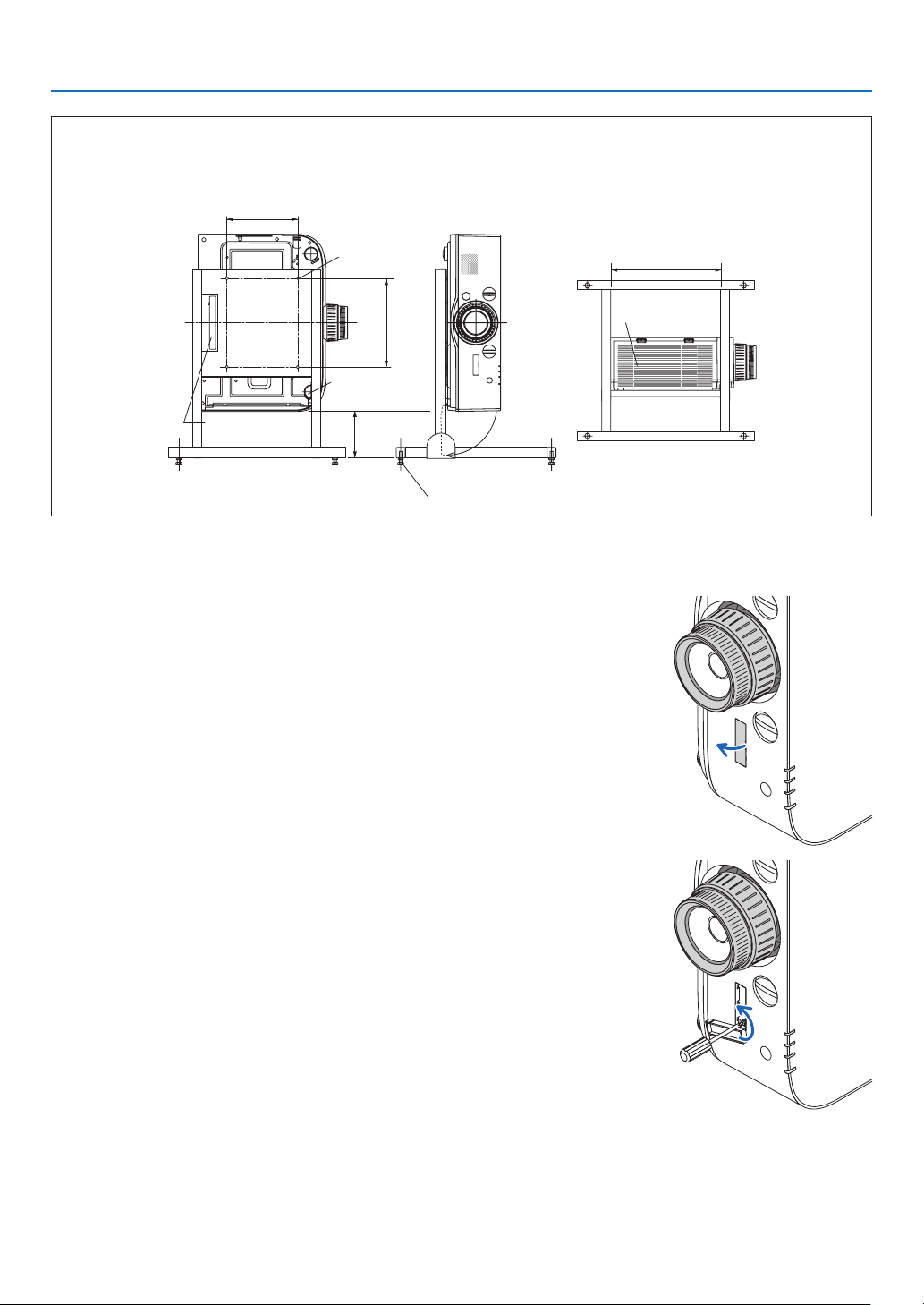
135
6. Installation and Connections
Reference drawings
* Thedrawingshowingthedimensionalrequirementsisnotanactualstanddesigndrawing.
[Side View] [Front View]
Screw holes for 4 -
M4 use
Tilt foot (remove)
130 or greater
200
Filter cover (when opened)
Horizontal adjuster
[Bottom View]
Filter cover
310 or greater
Rear foot
Lens shift securing method
1. Pull the securing lever cover towards you to remove it.
• Thecovercannotbedetachedfromtheprojector.
2. Turn the screws to the left to loosen them.
• Screwscannotberemoved.

136
6. Installation and Connections
3. Slide the securing lever towards the top until it comes to a stop
and then turn the screws to the right to tighten them.
• Tightenthescrewswhilepressingthesecuringlevertowardsthe
top.
* Loosenthescrewsrstbeforere-adjustingthelensshift.
4. Fix the four securing lever covers.
NOTE:
• Determinethescreenpositionrstbeforeusingthesecuringlevers.
• Donotturnthezoomringwhenusingthesecuringlever.Pleasedonotremovethelenseither.
• Thesecuringleverisusedtosupportthelensandnottosecurethelens.Asaresult,thescreenmayshiftwhenthelensis
touched.
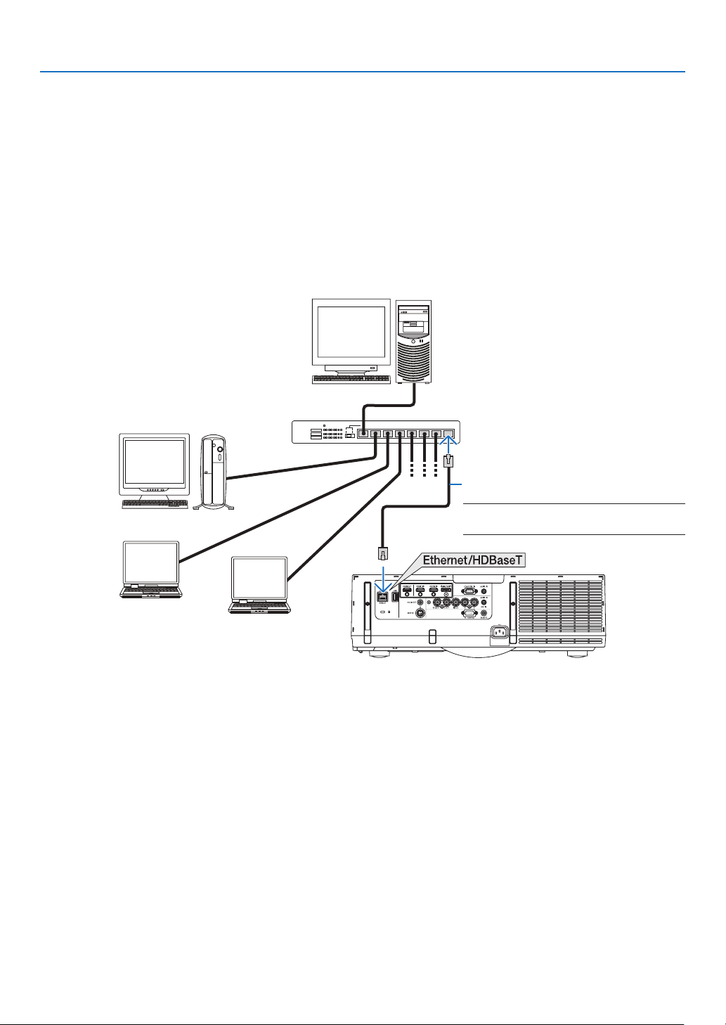
137
6. Installation and Connections
Connecting to a Wired LAN
TheprojectorcomesstandardwithaEthernet/HDBaseTport(RJ-45)whichprovidesaLANconnectionusingaLAN
cable.
TouseaLANconnection,youarerequiredtosettheLANontheprojectormenu.Select[SETUP]→[NETWORK
SETTINGS]→[WIREDLAN].(→page107).
Example of LAN connection
ExampleofwiredLANconnection
Server
Hub
LANcable(notsupplied)
NOTE: Use a Category 5 or higher LAN
cable.
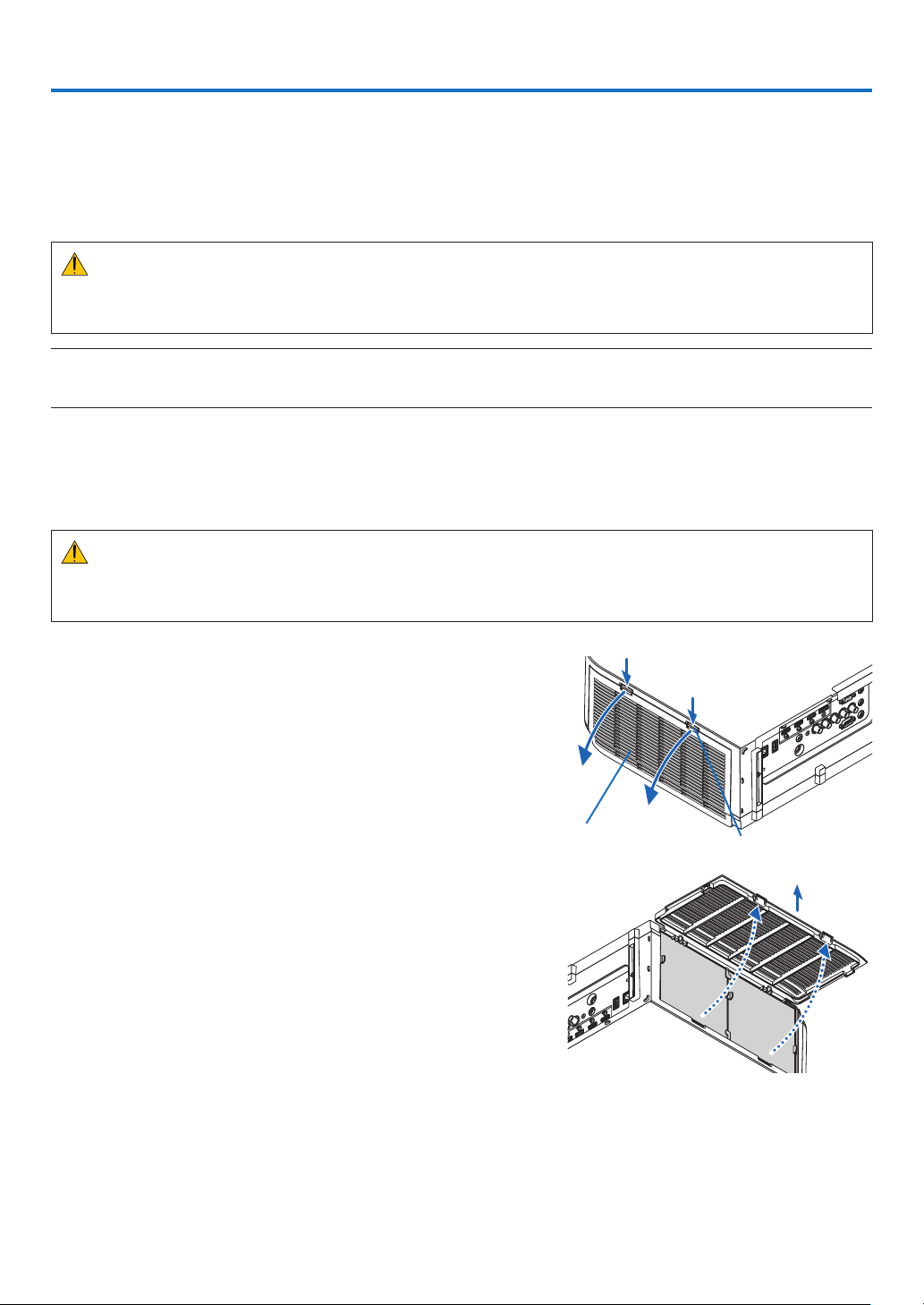
138
7. Maintenance
Thissectiondescribesthesimplemaintenanceproceduresyoushouldfollowtocleanthelters,thelens,thecabinet,
andtoreplacethelampandthelters.
❶ Cleaning the Filters
Theair-lterspongekeepsdustanddirtfromgettinginsidetheprojectorandshouldbefrequentlycleaned.Ifthelter
isdirtyorclogged,yourprojectormayoverheat.
WARNING
• Pleasedonotuseaspraycontainingammablegastoremovedustattachedtothelters,etc.Doingsomay
resultinres.
NOTE:Themessageforltercleaningwillbedisplayedforoneminuteaftertheprojectoristurnedonoroff.Whenthemessageis
displayed,cleanthelters.Thetimetocleantheltersissetto[OFF]attimeofshipment.(→ page 95)
To cancel the message, press any button on the projector cabinet or the remote control.
Thetwo-layerlter on the projector improves coolinganddust-proof capabilities compared with the conventional
models.
Theoutsides(intakeside)oftherstandsecondlayerltersremovedust.
Tocleanthelter,detachthelterunitandtheltercover.
CAUTION
• Beforecleaningthelters,turnofftheprojector,disconnectthepowercordandthenallowthecabinettocool.
Failuretodosocanresultinelectricshockorburninjuries.
1. Press down on the buttons on the left and right and then
pull the filter cover towards you to open it.
Thecoverwillopenabout90degreesbeforeitstops.
Filtercover Button
When mounting the projector to a ceiling
Theltercoverwillopenabout90degreesbeforeitcomestoa
stopatthestopperposition.Removeyourhandsasthestopper
willbedetachedifitisopenedfurther.Theltercoverwillstop
atapositionofabout90degrees.
However,theltercovermaycloseiftheprojectorvibrates.
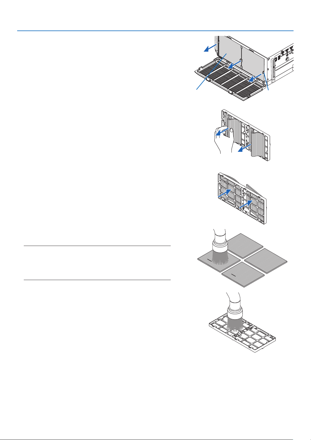
139
7. Maintenance
2. Remove the filter unit by pulling out the tab.
Filterunit Tab
3. Remove the four filters.
Holdandremovetheltersttedtothetwosidesofthelter
unit.
4. Use a vacuum cleaner to vacuum all the dust inside.
Getridofdustinthelter.
NOTE:
• Wheneveryouvacuumthelter,usethesoftbrushattachmentto
vacuum.Thisistoavoiddamagetothelter.
• Donotwashthelterwithwater.Doingsocanresultinlterclog-
ging.
5. Remove the dust on the front and back of the filter unit.
• Pleasealsoremovealldustfromtheltercoverofthepro-
jector.
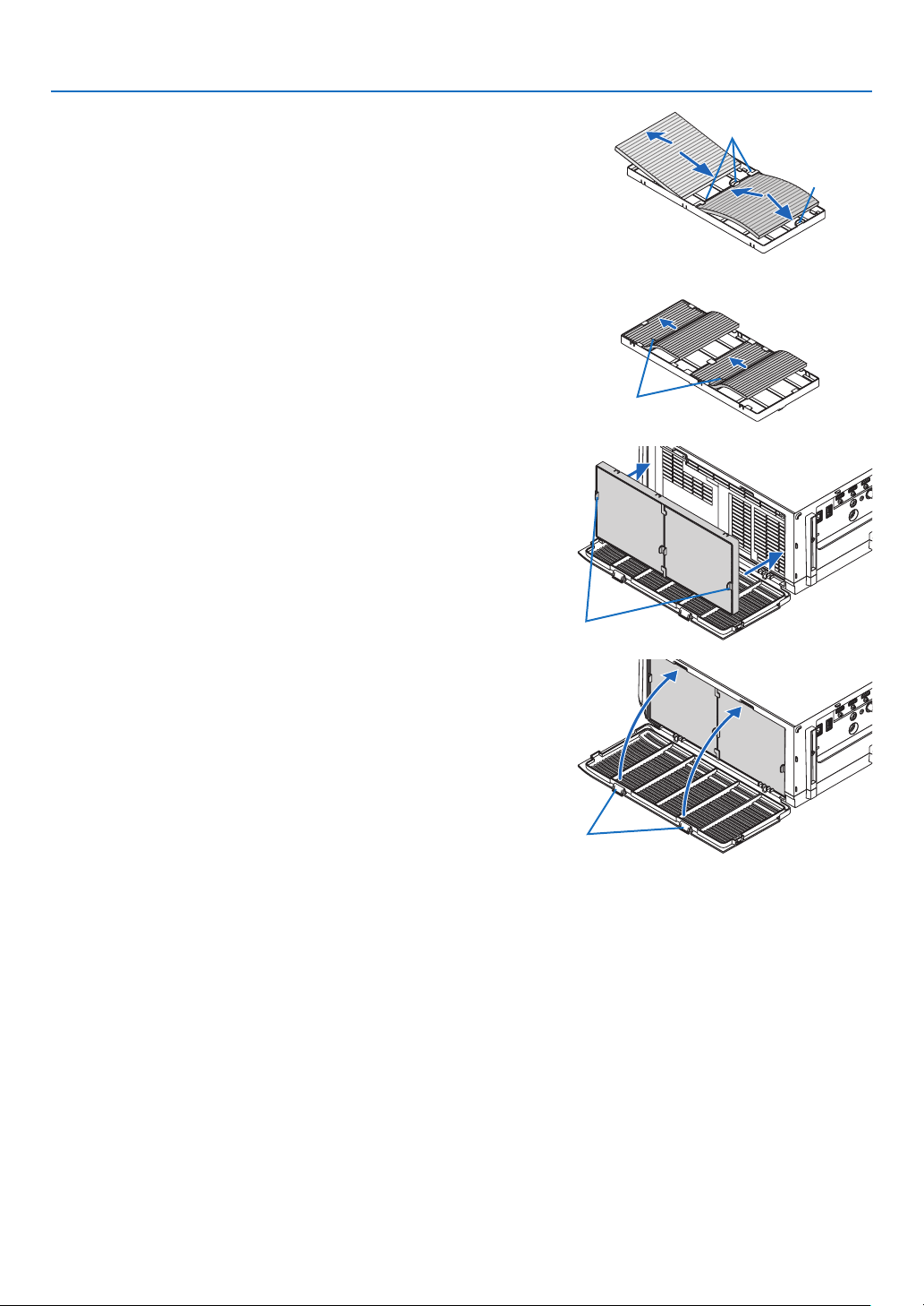
140
7. Maintenance
6. Attach 4 new filters to both sides of the filter unit.
The installation locations of the lters are differentiated by
whetherthereareanyslits(notches).Installthelterunderthe
angearoundthelterunitasfollows.
(1)Attachthe2lterswithtransparentframesttedtothegrips
tothesideofthelterunitwheretheknobislocated.
• Turnoverthesideofthelterwiththetransparentbox
andtheninstallit.
(2)Attachthe2lterswiththeblacklinestothesideofthelter
unitwherethereisnoknob.
• Turn over the side of the lter with the blackline,and
theninserttheslitsintotheprotrusionsonthelterunit
toinstallit.
Flange
Knob
Slit
7. Mount the filter unit back onto the projector cabinet.
Insertthelterunitontotheprojectorwiththesidesonwhich
theleftandrighthooksarelocatedontheoutside.
Hook
8. Closetheltercover.
Afterclosing,pushtheltercovernearthebuttonsuntila“click”
soundisheard.Theltercoverwillbesecuredinposition.
Button
9. Clearthelterusagehours.
Plugthepowercordintothewalloutlet,andthenturnonthe
projector.
Fromthemenu,select[RESET]→[CLEARFILTERHOURS].
(→page117)
Theintervaltimetocleantheltersissetto[OFF]attimeof
shipment.Whenusingtheprojectorasitis,youdonotclear
thelterusage
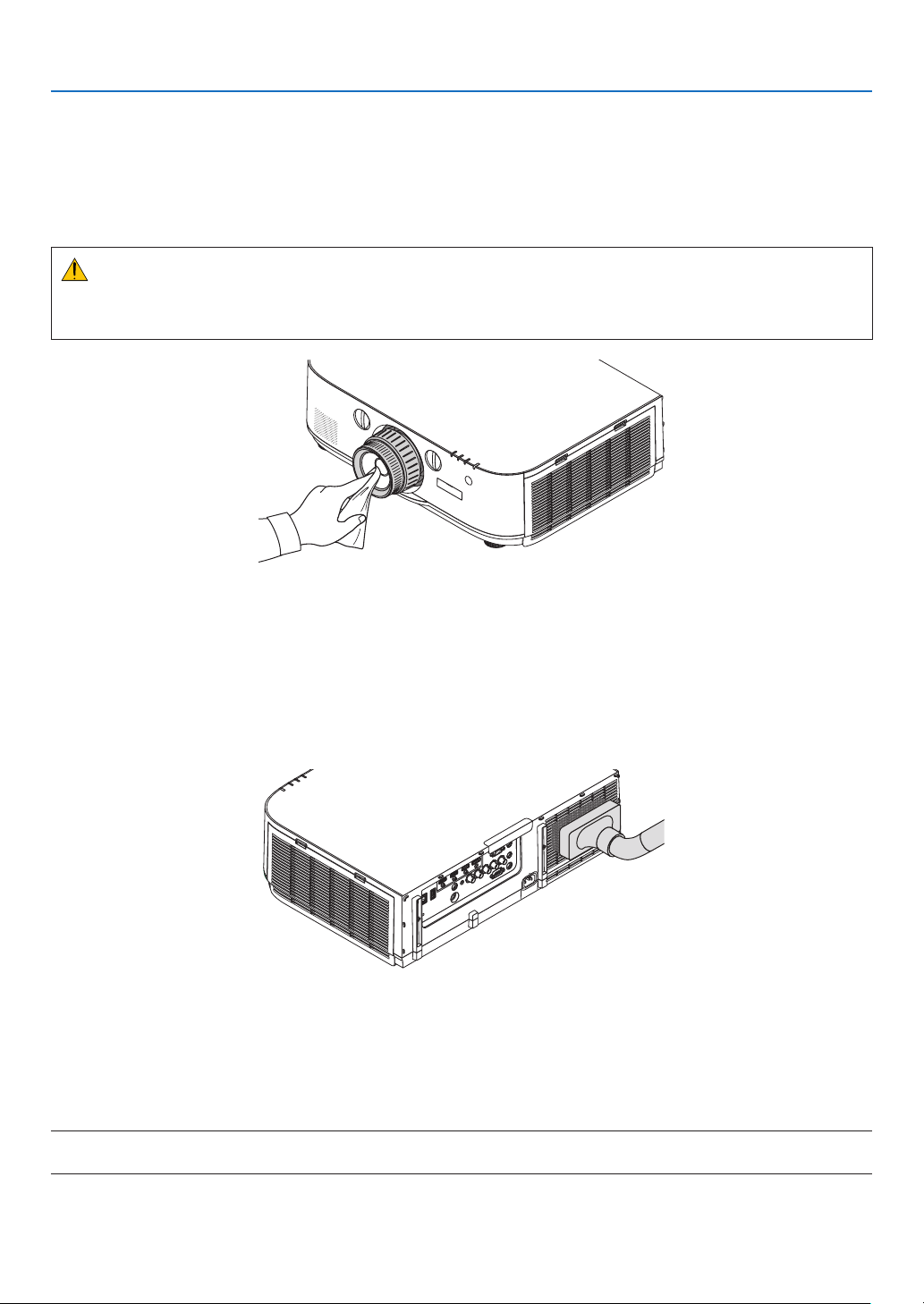
141
7. Maintenance
❷ Cleaning the Lens
• Turnofftheprojectorbeforecleaning.
• Theprojectorhasaplasticlens.Useacommerciallyavailableplasticlenscleaner.
• Donotscratchormarthelenssurfaceasaplasticlensiseasilyscratched.
• Neverusealcoholorglasslenscleanerasdoingsowillcausedamagetotheplasticlenssurface.
WARNING
• Pleasedonotuseaspraycontainingammablegastoremovedustattachedtothelens,etc.Doingsomay
resultinres.
❸ Cleaning the Cabinet
Turnofftheprojector,andunplugtheprojectorbeforecleaning.
• Useadrysoftclothtowipedustoffthecabinet.
Ifheavilysoiled,useamilddetergent.
• Neverusestrongdetergentsorsolventssuchasalcoholorthinner.
• Whencleaningtheventilationslitsorthespeakerusingavacuumcleaner,donotforcethebrushofthevacuum
cleanerintotheslitsofthecabinet.
Vacuumthedustofftheventilationslits.
• Cloggedventilationslitsmaycauseariseintheinternaltemperatureoftheprojector,resultinginmalfunction.
• Donotscratchorhitthecabinetwithyourngersoranyhardobjects
• Contactyourdealerforcleaningtheinsideoftheprojector.
NOTE:Donotapplyvolatileagentsuchasinsecticideonthecabinet,thelens,orthescreen.Donotleavearubberorvinylproduct
inprolongedcontactwithit.Otherwisethesurfacenishwillbedeterioratedorthecoatingmaybestrippedoff.

142
7. Maintenance
❹ Replacing the Lamp and the Filters
Whenthelampreachestheendofitslife,theLAMPindicatorinthecabinetwillblinkredandthemessage“THE
LAMPHASREACHEDTHEENDOFITSUSABLELIFE.PLEASEREPLACETHELAMPANDFILTER.USETHE
SPECIFIEDLAMPFORSAFETYANDPERFORMANCE.”willappear(*).Eventhoughthelampmaystillbeworking,
replacethelamptomaintaintheoptimalprojectorperformance.Afterreplacingthelamp,besuretoclearthelamp
hourmeter.(→page116)
CAUTION
• DONOTTOUCHTHELAMPimmediatelyafterithasbeenused.Itwillbeextremelyhot.Turntheprojectoroff
andthendisconnectthepowercord.Allowatleastonehourforthelamptocoolbeforehandling.
• Usethespeciedlampforsafetyandperformance.
• DONOTREMOVEANYSCREWSexceptonelampcoverscrewandtwolamphousingscrews.Youcouldreceive
anelectricshock.
• Donotbreaktheglassonthelamphousing.
Keepngerprintsofftheglasssurfaceonthelamphousing.Leavingngerprintsontheglasssurfacemightcause
anunwantedshadowandpoorpicturequality.
• Theprojectorwillturnoffandgointostandbymodewhenyoucontinuetousetheprojectorforanother100hours
afterthelamphasreachedtheendofitslife.Ifthishappens,besuretoreplacethelamp.Ifyoucontinuetouse
thelampafterthelampreachestheendofitslife,thelampbulbmayshatter,andpiecesofglassmaybescattered
inthelampcase.Donottouchthemasthepiecesofglassmaycauseinjury.Ifthishappens,contactyourNEC
dealerforlampreplacement.
*NOTE: This message will be displayed under the following conditions:
• foroneminuteaftertheprojectorhasbeenpoweredon
• whenthe (POWER)buttonontheprojectorcabinetortheSTANDBYbuttonontheremotecontrolispressed
To turn off the message, press any button on the projector cabinet or the remote control.
Optionallampandtoolsneededforreplacement:
• Phillipsscrewdriver(plus-head)
• Replacementlamp:
NP26LP
Flow of Replacing the Lamp and the Filters
Step 1. Replace the lamp
Step 2. Replace the filters (→ page 145)
Step 3. Clearthelampusagehoursandthelterusagehours(→ page 116, 117)
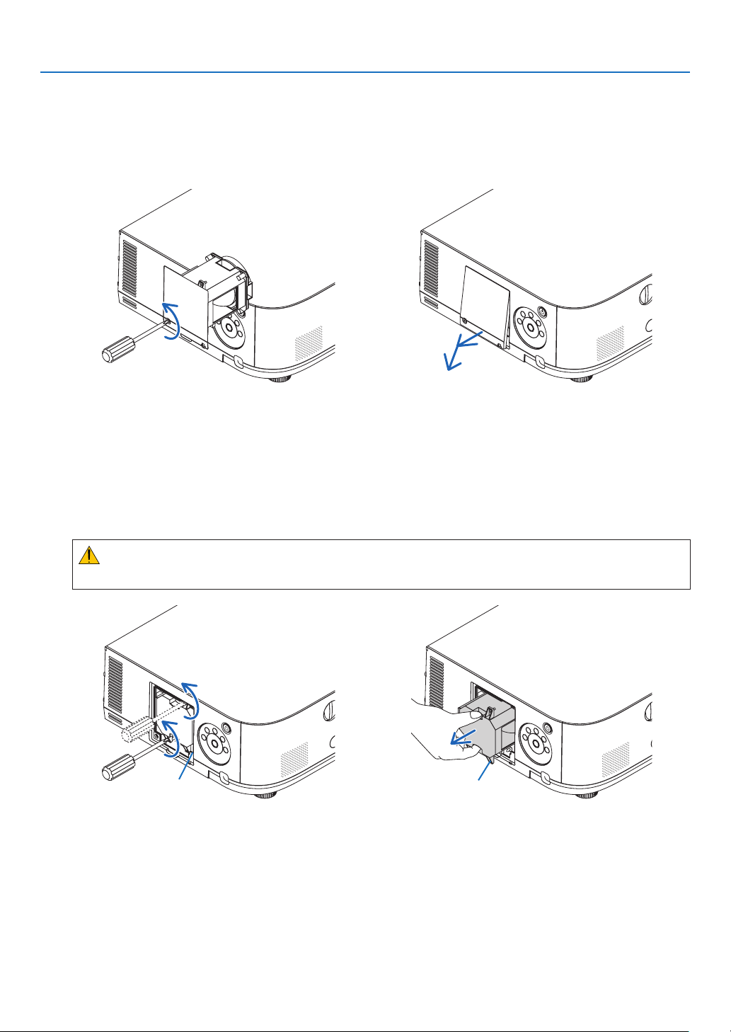
143
7. Maintenance
To replace the lamp:
1. Remove the lamp cover.
(1)Loosenthelampcoverscrew
• Thelampcoverscrewisnotremovable.
(2)Pullthebottomofthelampcovertowardsyouandremoveit.
2. Remove the lamp housing.
(1)Loosenthetwoscrewssecuringthelamphousinguntilthephillipsscrewdrivergoesintoafreewheelingcondi-
tion.
• Thetwoscrewsarenotremovable.
• Thereisaninterlockonthiscasetopreventtheriskofelectricalshock.Donotattempttocircumventthis
interlock.
(2)Removethelamphousingbyholdingit.
CAUTION:
Makesurethatthelamphousingiscoolenoughtobeforeremovingit.
Interlock Guidehole
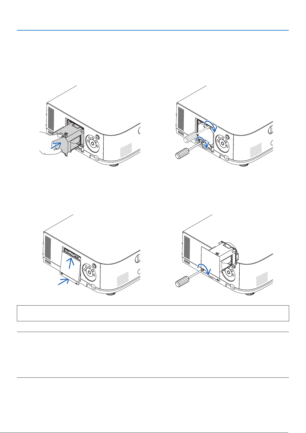
144
7. Maintenance
3. Install a new lamp housing.
(1)Insertanewlamphousinguntilthelamphousingispluggedintothesocket.
(2)Positionsothattheguideholeinthebottomrightofthelamphouseisovertheprotrusionontheprojectorthen
pressallthewayin.
(3)Secureitinplacewiththetwoscrews.
• Besuretotightenthescrews.
4. Reattach the lamp cover.
(1)Insertthetopedgeofthelampcoverintothegrooveintheprojectorandclosethelampcover.
(2)Tightenthescrewtosecurethelampcover.
• Besuretotightenthescrew.
This completes the lamp replacement.
Goontothelterreplacement.
NOTE:
• Whenyoucontinuetousetheprojectorforanother100hoursafterthelamphasreachedtheendofitslife,theprojectorcannot
turnonandthemenuisnotdisplayed.Ifthishappens,presstheHELPbuttonontheremotecontrolfor10secondstoresetthe
lampclockbacktozero.Whenthelamptimeclockisresettozero,theLAMPindicatorgoesout.
• Forportraitprojection,thepowersupplywillbeswitchedoffwhenthelampreplacementtime(estimated)*isreached.Alamp
replacement message will be displayed 100 hours before the lamp replacement time is reached.
* The replacement time is not guaranteed.
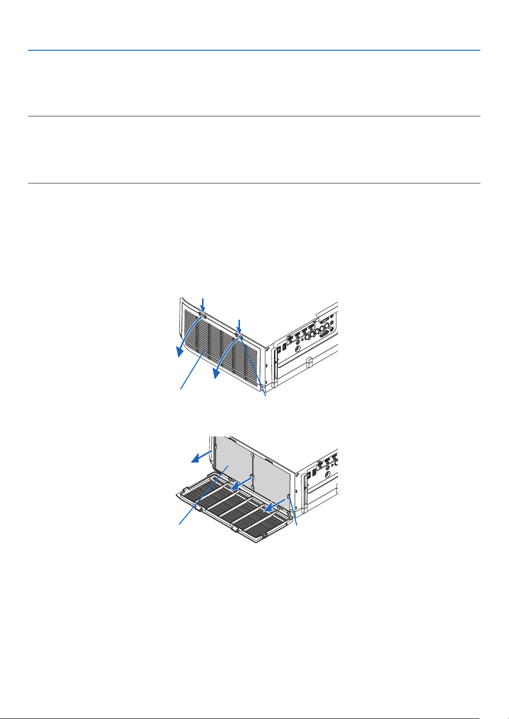
145
7. Maintenance
Toreplacethelters:
Fourltersarepackagedwiththereplacementlamp.
Honeycomblter(coarsemesh):Largeandsmallsizes(attachedtotheoutsideofthelterunit)
Accordionlter(nemesh):Largeandsmallsizes(attachedtotheinsideofthelterunit)
NOTE:
• Replaceallfourltersatthesametime.
• Beforereplacingthelters,wipeoffdustanddirtfromtheprojectorcabinet.
• Theprojectorisprecisionequipment.Keepoutdustanddirtduringlterreplacement.
• Donotwashthelterswithsoapandwater.Soapandwaterwilldamagetheltermembrane.
• Putltersintoplace.Incorrectattachmentofaltermaycausedustanddirttogetintotheinsideoftheprojector.
Beforereplacingthelters,replacethelamp.(→page143)
1. Press down on the buttons on the left and right and then pull the filter cover towards you to open it.
Thecoverwillopenabout90degreesbeforeitstops.
When mounting the projector to a ceiling
Theltercoverwillopenabout90degreesbeforeitcomestoastopatthestopperposition.Removeyourhands
asthestopperwillbedetachedifitisopenedfurther.Theltercoverwillstopatapositionofabout90degrees.
However,theltercovermaycloseiftheprojectorvibrates.
Filtercover Button
2. Remove the filter unit by pulling out the tab.
Filterunit Tab
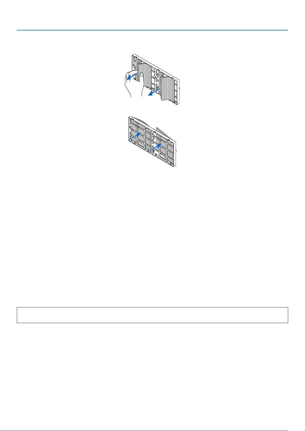
146
7. Maintenance
3. Remove the four filters.
Holdontotheltersttedtobothsidesofthelterunittoremovethelterunit.
4. Remove dust from the filter unit and the filter cover.
Cleanbothoutsideandinside.
5. Attach 4 new filters to both sides of the filter unit.
Theinstallationlocationsoftheltersaredifferentiatedbywhetherthereareanyslits(notches).Installthelter
undertheangearoundthelterunitasfollows.
(1)Attachthe2lterswithtransparentframesttedtothegripstothesideofthelterunitwheretheknobislo-
cated.
• Turnoverthesideofthelterwiththetransparentboxandtheninstallit.
(2)Attachthe2lterswiththeblacklinestothesideofthelterunitwherethereisnoknob.
• Turnoverthesideofthelterwiththeblackline,andtheninserttheslitsintotheprotrusionsonthelterunit
toinstallit.
6. Mount the filter unit back onto the projector cabinet.
Insertthelterunitontotheprojectorwiththesidesonwhichtheleftandrighthooksarelocatedontheoutside.
7. Closetheltercover.
Afterclosing,pushtheltercovernearthebuttonsuntila“click”soundisheard.Theltercoverwillbesecuredin
position.
Thiscompletesthelterreplacement.
Goontotheclearinglampandlterhourmeters.
Toclearthelampusagehoursandthelterusagehours:
1. Place the projector where you use it.
2. Plug the power cord into the wall outlet, and then turn on the projector.
3. Clearthelampusagehoursandthelterusagehours.
1. Fromthemenu,select[RESET]→[CLEARLAMPHOURS]andresetthelampusagehours.
2. Select[CLEARFILTERHOURS]andresetthelterusagehours.(→page117)

147
8. User Supportware
❶ Operating Environment for Software Included on CD-ROM
Names and Features of Bundled Software Programs
Nameofsoftwareprogram Features
VirtualRemoteTool
(Windowsonly)
Whenthecomputerandprojectorareconnectedusinganetwork(wiredLAN),
suchoperationsasturningtheprojector’spoweronandoffandswitchingthe
signalcanbeperformed.Itisalsopossibletosendanimagetotheprojector
andregisteritasthebackgroundlogo.Oncetheimageisregistered,itcanbe
lockedtopreventthelogofrombeingoverwritten.
PCControlUtilityPro4
PCControlUtilityPro5(forMac
OS)
Thisisasoftwareprogramusedtooperatetheprojectorfromthecomputerwhen
thecomputerandtheprojectorareconnectedwithLAN.(→page137)
• PCControlUtilityPro4canbeusedwithaserialconnection.
* ThefollowingthreesoftwareontheCD-ROMcannotbeusedinthisdevice.
ImageExpressUtilityLite(forWindows/MacOS),ImageExpressUtility2.0(forWindows)andDesktopControl
Utility1.0(forWindows)
Download service
Fortheupdateinformationaboutthesesoftwareprograms,visitourwebsite:
URL:http://www.nec-display.com/dl/en/index.html
Operating Environment
ThefollowingistheoperatingenvironmentforImageExpressUtilityLite.Fortheoperatingenvironmentofothersoft-
wareprogram,refertothehelpfunctionofeachsoftwareprogram.
[Windows]
SupportedOS Windows8(CoreEdition)
Windows8Pro
Windows8Enterprise
Windows7HomeBasic
Windows7HomePremium
Windows7Professional
Windows7Ultimate
Windows7Enterprise
WindowsVistaHomeBasic
WindowsVistaHomePremium
WindowsVistaBusiness
WindowsVistaUltimate
WindowsVistaEnterprise
WindowsXPHomeEdition(32-bitversion)ServicePack3orlater
WindowsXPProfessional(32-bitversion)ServicePack3orlater
• Windowspower-savingfunctionisnotsupported.
• Tousetheaudiotransfercapability,Windows8/Windows7/WindowsVista
ServicePack1orlaterisrequired.
[Mac]
SupportedOS MacOSXv10.6,v10.7,v10.8
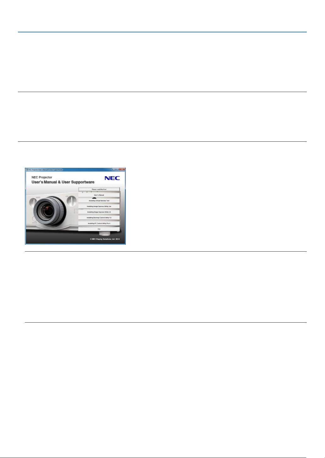
148
8. User Supportware
❷ Installing Software Program
Installation for Windows software
ThesoftwareprogramsexceptPCControlUtilityPro5supportWindows8,Windows7,WindowsVista,andWindows
XP.
NOTE:
• Toinstalloruninstalleachsoftwareprogram,theWindowsuseraccountmusthave“Administrator”privilege(Windows8,Win-
dows7,WindowsVista)or“ComputerAdministrator”privilege(WindowsXP).
• Exitallrunningprogramsbeforeinstallation.Ifanotherprogramisrunning,theinstallationmaynotbecompleted.
• TorunVirtualRemoteToolorPCControlUtilityPro4onWindows8,WindowsXPHomeEdition,andWindowsXPProfessional,
“Microsoft.NETFrameworkVersion2.0”isrequired.TheMicrosoft.NETFrameworkVersion2.0,3.0or3.5isavailablefrom
Microsoft’swebpage.Downloadandinstallitonyourcomputer.
1 InserttheaccompanyingNECProjectorCD-ROMintoyourCD-ROMdrive.
Themenuwindowwillbedisplayed.
TIP:
If the menu window will not be displayed, try the following procedure.
ForWindows7
1. Click“start”onWindows.
2. Click“AllPrograms”→ “Accessories” → “Run”.
3. Type your CD-ROM drive name (example:“Q:\”) and“LAUNCHER.EXE” in“Name”. (example: Q:\
LAUNCHER.EXE)
4. Click“OK”.
Themenuwindowwillbedisplayed.

149
8. User Supportware
2 Clickasoftwareprogramyouwishtoinstallonthemenuwindow.
Theinstallationwillstart.
• Followtheinstructionsontheinstallerscreenstocompletetheinstallation.
TIP:
Uninstalling a Software Program
Preparation:
Exitthe softwareprogrambeforeuninstalling.Touninstall thesoftwareprogram,theWindowsuseraccountmust
have“Administrator”privilege (Windows8,Windows7, andWindowsVista)or“ComputerAdministrator”privilege
(WindowsXP).
•ForWindows8/Windows7/WindowsVista
1 Click“Start”andthen“ControlPanel”.
TheControlPanelwindowwillbedisplayed.
2 Click“Uninstallaprogram”under“Programs”
The“ProgramsandFeatures”windowwillbedisplayed.
3 Select the software program and click it.
4 Click“Uninstall/Change”or“Uninstall”.
•Whenthe“UserAccountControl”windowsisdisplayed,click“Continue”.
Followtheinstructionsonthescreenstocompletetheuninstallation.
•ForWindowsXP
1 Click“Start”andthen“ControlPanel”.
TheControlPanelwindowwillbedisplayed.
2 Double-click “Add / Remove Programs”.
TheAdd/RemoveProgramswindowwillbedisplayed.
3 Clickthesoftwareprogramfromthelistandthenclick“Remove”.
Followtheinstructionsonthescreenstocompletetheuninstallation.

150
8. User Supportware
Using on Mac OS
Step 1: Install PC Control Utility Pro 5 on the computer.
1. InserttheaccompanyingNECProjectorCD-ROMinyourMacCD-ROMdrive.
TheCD-ROMiconwillbedisplayedonthedesktop.
2. Double-clicktheCD-ROMicon.
TheCD-ROMwindowwillbedisplayed.
3. Double-click the “Mac OS X” folder.
4. Double-click“PCControlUtility.mpkg”.
Theinstallerwillstart.
5. Click“Next”.
“ENDUSERLICENSEAGREEMENT”screenwillbedisplayed.
6. Read“ENDUSERLICENSEAGREEMENT”andclick“Next”.
Theconrmationwindowwillbedisplayed
7. Click“Iacceptthetermsinthelicenseagreement”.
Followtheinstructionsontheinstallerscreenstocompletetheinstallation.
TIP:
•Uninstallingasoftwareprogram
1. Putthe“PCControlUtilityPro5”foldertotheTrashicon.
2. PutthecongurationleofPCControlUtilityPro5totheTrashicon.
• ThecongurationleofPCControlUtilityPro5islocatedin“/Users/<yourusername>/ApplicationData/NEC
ProjectorUserSupportware/PCControlUtilityPro5”.
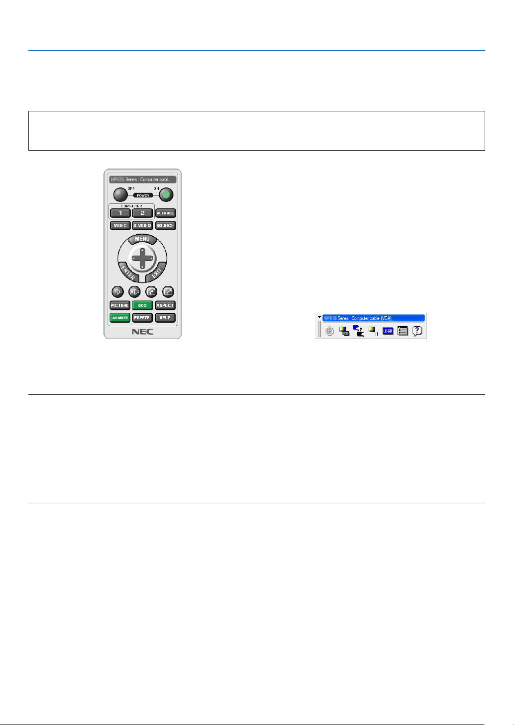
151
8. User Supportware
❸ Operating the Projector Via the LAN (Virtual Remote Tool)
Thiswillhelpyouperformoperationssuchasprojector’spoweronoroffandsignalselectionviaaLANconnection.It
isalsousedtosendanimagetotheprojectorandregisteritasthelogodataoftheprojector.Afterregisteringit,you
canlockthelogotopreventitfromchanging.
Control Functions
PowerOn/Off,signalselection,picturefreeze,picturemute,audiomute,Logotransfertotheprojector,andremote
controloperationonyourPC.
VirtualRemotescreen
RemoteControlWindow Toolbar
ThissectionprovidesanoutlineofpreparationforuseofVirtualRemoteTool.
ForinformationonhowtouseVirtualRemoteTool,seeHelpofVirtualRemoteTool.(→page153)
NOTE:
• Logodata(graphics)thatcanbesenttotheprojectorwithVirtualRemoteToolhasthefollowingrestrictions:
(OnlyviaserialorLANconnection)
* Filesize:Within256kilobytes
* Imagesize:Withintheresolutionoftheprojector
* Fileformat:PNG(Fullcolor)
• Logodata(image)sentusingtheVirtualRemoteToolwillbedisplayedinthecenterwiththesurroundingareainblack.
• Toputthedefault“NEClogo”backinthebackgroundlogo,youneedtoregisteritasthebackgroundlogobyusingtheimage
le (PA622U/NP-PA522U: \Logo\necpj_bbwux.png, PA672W/PA572W: \Logo\necpj_bbwx.png, PA722X/NP-PA622X: \Logo\
necpj_bb_x.png)includedonthesuppliedNECProjectorCD-ROM.
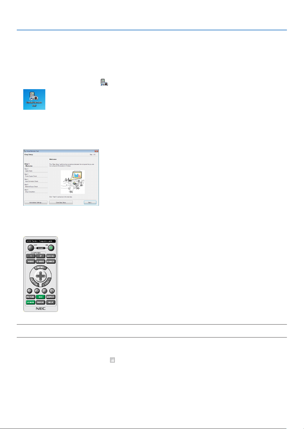
152
8. User Supportware
Connect the projector to a LAN.
ConnecttheprojectortotheLANbyfollowingtheinstructionsin“ConnectingtoaWiredLAN”(→page137)and“9.
ControllingtheProjectorbyUsinganHTTPBrowser”(→page42)
Start Virtual Remote Tool
Start using the shortcut icon
• Double-clicktheshortcuticon on the Windows Desktop.
Start from the Start menu
• Click[Start]→[AllPrograms]or[Programs]→[NECProjectorUserSupportware]→[VirtualRemoteTool]
→[VirtualRemoteTool].
WhenVirtualRemoteToolstartsforthersttime,“EasySetup”windowwillbedisplayed.
Followtheinstructionsonthescreens
When“EasySetup”iscompleted,theVirtualRemoteToolscreenwillbedisplayed.
NOTE:
• When[NORMAL]isselectedfor[STANDBYMODE]fromthemenu,theprojectorcannotbeturnedonvianetworkconnection.
TIP:
• TheVirtualRemoteToolscreen(orToolbar)canbedisplayedwithoutdisplaying“EasySetup”window.
Todoso,clicktoplaceacheckmarkfor“ DonotuseEasySetupnexttime”onthescreenatStep6in“EasySetup”.
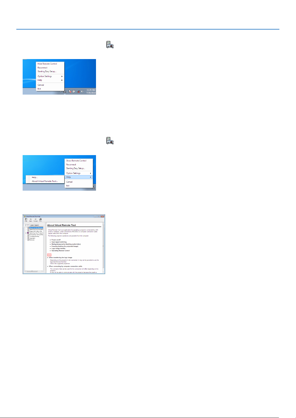
153
8. User Supportware
ExitingVirtualRemoteTool
1 ClicktheVirtualRemoteToolicon on the Taskbar.
Thepop-upmenuwillbedisplayed.
2 Click“Exit”.
TheVirtualRemoteToolwillbeclosed.
ViewingthehelpleofVirtualRemoteTool
•Displayingthehelpleusingthetaskbar
1 ClicktheVirtualRemoteToolicon onthetaskbarwhenVirtualRemoteToolisrunning.
Thepop-upmenuwillbedisplayed.
2. Click“Help”.
TheHelpscreenwillbedisplayed.
•DisplayingthehelpleusingtheStartMenu.
1. Click“Start”.“Allprograms”or“Programs”.“NECProjectorUserSupportware”.“VirtualRemoteTool”.and
then“VirtualRemoteToolHelp”inthisorder.
TheHelpscreenwillbedisplayed.
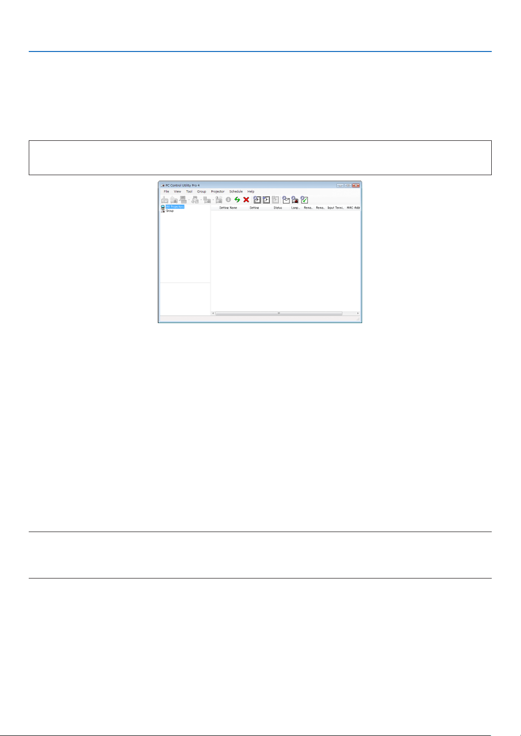
154
8. User Supportware
❹
Controlling the Projector over a LAN (PC Control Utility Pro 4/
Pro 5)
Usingtheutilitysoftware“PCControlUtilityPro4”or“PCControlUtilityPro5”includedonthecompanionNECPro-
jectorCD-ROM,theprojectorcanbecontrolledfromacomputeroveraLAN.
PCControlUtilityPro4isaprogramcompatiblewithWindows.(→thispage)
PCControlUtilityPro5isaprogramcompatiblewithMacOS.(→page157)
Control Functions
PowerOn/Off,signalselection,picturefreeze,picturemute,audiomute,adjusting,errormessagenotication,event
schedule.
ScreenofPCControlUtilityPro4
ThissectionprovidesanoutlineofpreparationforuseofPCControlUtilityPro4/Pro5.Forinformationonhowtouse
PCControlUtilityPro4/Pro5,seeHelpofPCControlUtilityPro4/Pro5.(→page156,157)
Step1:InstallPCControlUtilityPro4/Pro5onthecomputer.
Step2:ConnecttheprojectortoaLAN.
Step3:StartPCControlUtilityPro4/Pro5.
• TorunPCControlUtilityPro4onWindows8,WindowsXPHomeEditionandWindowsXPProfessional,“Microsoft
.NETFramework”isrequired.TheMicrosoft.NETFrameworkVersion2.0,3.0or3.5isavailablefromMicrosoft’s
webpage.Downloadandinstalltheitonyourcomputer.
TIP:
• PCControlUtilityPro4canbeusedwithaserialconnection.
Using on Windows
Step 1: Install PC Control Utility Pro 4 on the computer
NOTE:
• Toinstalloruninstalltheprogram,theWindowsuseraccountmusthave[Administrator]privilege(Windows8,Windows7,
WindowsVistaandWindowsXP)
• Exitallrunningprogramsbeforeinstallation.Ifanotherprogramisrunning,theinstallationmaynotbecompleted.
1 InserttheaccompanyingNECProjectorCD-ROMintoyourCD-ROMdrive.
Themenuwindowwillbedisplayed.
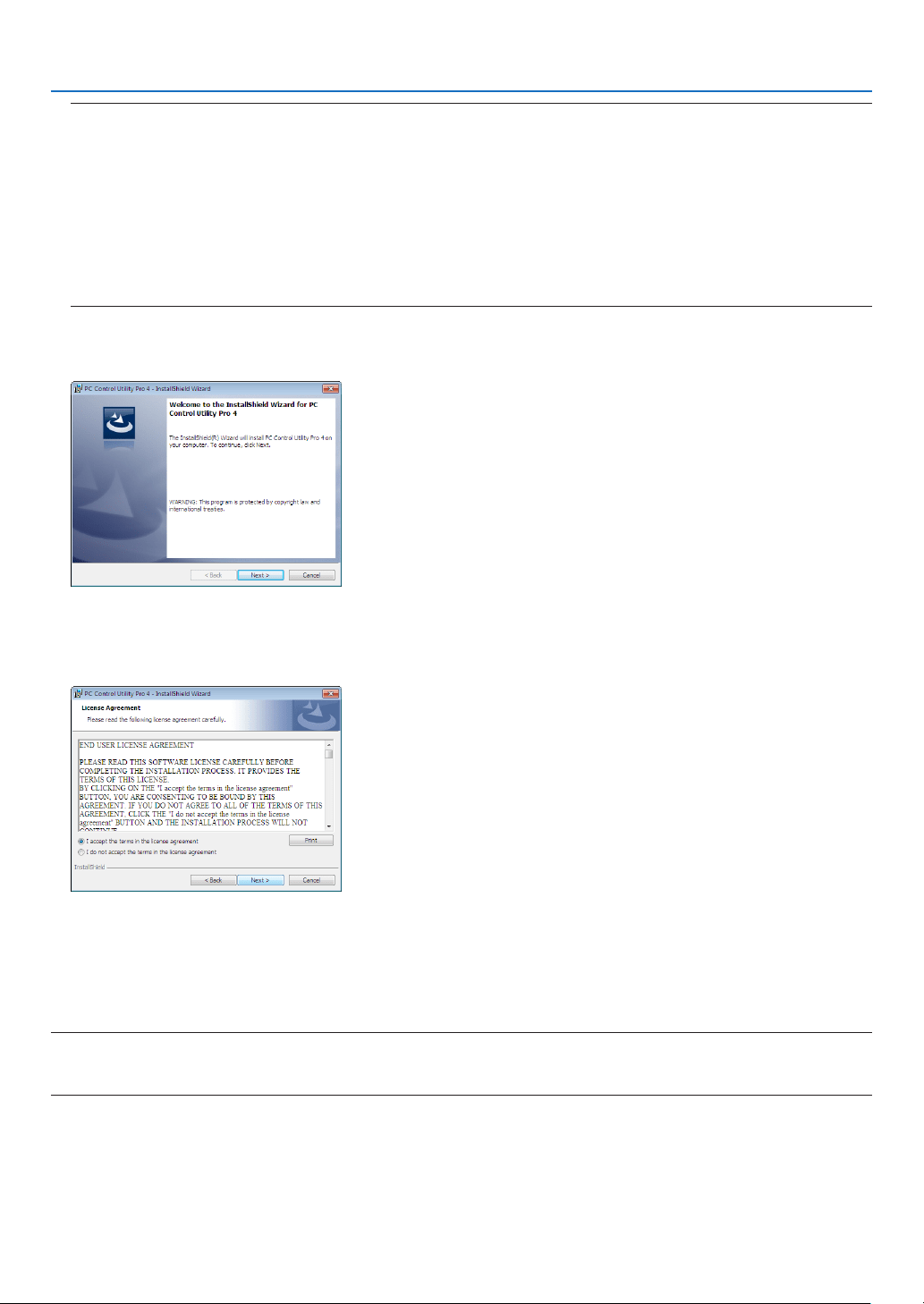
155
8. User Supportware
TIP:
If the menu window will not be displayed, try the following procedure.
ForWindows7:
1. Click“start”onWindows.
2. Click“AllPrograms”→ “Accessories” → “Run”.
3. Type your CD-ROM drive name (example:“Q:\”) and“LAUNCHER.EXE” in“Name”. (example: Q:\
LAUNCHER.EXE)
4. Click“OK”.
themenuwindowwillbedisplayed.
2 Click“PCControlUtilityPro4”onthemenuwindow.
Theinstallationwillstart.
Whentheinstallationiscomplete,theWelcomewindowwillbedisplayed.
3 Click“Next”.
“ENDUSERLICENSEAGREEMENT”screenwillbedisplayed.
Read“ENDUSERLICENSEAGREEMENT”carefully.
4 If you agree, click “I accept the terms in the license agreement” and then click “Next”.
• Followtheinstructionsontheinstallerscreenstocompletetheinstallation.
• Whentheinstallationiscomplete,youwillreturntothemenuwindow.
TIP:
•UninstallingPCControlUtilityPro4
TouninstallPCControlUtilityPro4,dothesameproceduresstatedasin“UninstallingaSoftwareProgram”.(→ page 149)

156
8. User Supportware
Step 2: Connect the projector to a LAN.
ConnecttheprojectortotheLANbyfollowingtheinstructionsin“ConnectingtoaWiredLAN”(→page137)and“9.
ControllingtheProjectorbyUsinganHTTPBrowser”(→page42)
Step 3: Start PC Control Utility Pro 4
Click“Start”→“Allprograms”or“Programs”→“NECProjectorUserSupportware”→“PCControlUtilityPro4”→
“PCControlUtilityPro4”.
NOTE:
• FortheSchedulefunctionofthePCControlutilityPro4towork,youmusthaveyourcomputerrunningandnotinstandby/
sleepmode.Select“PowerOptions”fromthe“ControlPanel”inWindowsanddisableitsstandby/sleepmodebeforerunningthe
scheduler.
[Example]ForWindows7:
Select“ControlPanel”→“SystemandSecurity”→“PowerOptions”→“Changewhenthecomputersleeps”→“Putthecomputer
tosleep”→“Never”.
NOTE:
• When[NORMAL]isselectedfor[STANDBYMODE]fromthemenu,theprojectorcannotbeturnedonviathenetwork(wiredLAN)
connection.
TIP:
ViewingtheHelpofPCControlUtilityPro4
• DisplayingtheHelpleofPCControlUtilityPro4whileitisrunning.
Click“Help(H)”→“Help(H)…”ofwindowofPCControlUtilityPro4inthisorder.
Thepop-upmenuwillbedisplayed.
• DisplayingthehelpleusingtheStartMenu.
Click“Start”→“Allprograms”or“Programs”→“NECProjectorUserSupportware”→“PCControlUtilityPro4”→
“PCControlUtilityPro4Help”.
TheHelpscreenwillbedisplayed.

157
8. User Supportware
Using on Mac OS
Step 1: Install PC Control Utility Pro 5 on the computer
1. InserttheaccompanyingNECProjectorCD-ROMinyourMacCD-ROMdrive.
TheCD-ROMiconwillbedisplayedonthedesktop.
2. Double-clicktheCD-ROMicon.
TheCD-ROMwindowwillbedisplayed.
3. Double-click the “Mac OS X” folder.
4. Double-click“PCControlUtility.mpkg”.
Theinstallerwillstart.
5. Click“Next”.
“ENDUSERLICENSEAGREEMENT”screenwillbedisplayed.
6. Read“ENDUSERLICENSEAGREEMENT”andclick“Next”.
Theconrmationwindowwillbedisplayed
7. Click“Iacceptthetermsinthelicenseagreement”.
Followtheinstructionsontheinstallerscreenstocompletetheinstallation.
Step 2: Connect the projector to a LAN
ConnecttheprojectortotheLANbyfollowingtheinstructionsin“ConnectingtoaWiredLAN”(→page137)and“❾
ControllingtheProjectorbyUsinganHTTPBrowser”(→page42)
Step 3: Start PC Control Utility Pro 5
1. Open your Applications folder in Mac OS.
2. Clickthe“PCControlUtilityPro5”folder.
3. Clickthe“PCControlUtilityPro5”icon.
PCControlUtilityPro5willstart.
NOTE:
• FortheSchedulefunctionofthePCControlutilityPro5towork,youmusthaveyourcomputerrunningandnotinsleepmode.
Select“EnergySaver”fromthe“SystemPreferences”inMacanddisableitssleepmodebeforerunningthescheduler.
• When[NORMAL]isselectedfor[STANDBYMODE]fromthemenu,theprojectorcannotbeturnedonviathenetwork(wiredLAN)
connection.
TIP:
ViewingtheHelpofPCControlUtilityPro5
•DisplayingtheHelpleofPCControlUtilityPro5whileitisrunning.
• Fromthemenubar,click“Help”→“Help”inthisorder.
TheHelpscreenwillbedisplayed.
•DisplayingtheHelpusingtheDock
1. Open “Application Folder” in Mac OS.
2. Clickthe“PCControlUtilityPro5”folder.
3. Clickthe“PCControlUtilityPro5Help”icon.
TheHelpscreenwillbedisplayed.

158
9. Appendix
❶ Throw distance and screen size
Sixseparatebayonetstylelensescanbeusedonthisprojector.Refertotheinformationonthispageandusealens
suitedfortheinstallationenvironment(screensizeandthrowdistance).Forinstructionsonmountingthelens,see
page123.
Lens types and throw distance
PA722X/PA622X
Screensize Lensmodelname
NP11FL NP30ZL NP12ZL NP13ZL NP14ZL NP15ZL
30"
0.7-0.9
40" 0.6 0.9-1.2 1.2 - 2.4
60" 1.0
1.0-1.3 1.4-1.9 1.8-3.7 3.6-5.8 5.7 - 8.7
80" 1.3
1.3-1.7 1.9-2.5 2.4-4.9 4.8 - 7.8 7.6 - 11.6
100" 1.6 1.6 - 2.1
2.4-3.2 3.0-6.1 6.0-9.7 9.6-14.6
120" 2.0 2.0 - 2.6 2.9-3.8 3.7-7.4 7.3-11.7 11.5 - 17.6
150" 2.5
2.5-3.2 3.7-4.8 4.6-9.2 9.1-14.7 14.4 - 22.0
200"
3.3-4.3 4.9-6.4 6.1-12.3 12.2-19.6 19.3-29.4
240" 4.0 - 5.2 5.9-7.7 7.4 - 14.8 14.7-23.6 23.2-35.3
300" 5.0 - 6.5 7.4-9.6 9.2-18.5 18.4-29.5 29.1-44.2
400" 6.7 - 7.7 9.8-12.8 12.3-24.7 24.6-39.4 38.8-59.0
500" 8.4-10.9 12.3-16.0 15.4-30.8 30.7-49.2 48.6-73.8
TIP
Calculationofthethrowdistancefromthescreensize
NP11FLlensthrowdistance(m)=H×0.8:0.6m(min.)to2.5m(max.)
NP30ZLlensthrowdistance(m)=H×0.8toH×1.1:1.0m(min.)to10.9m(max.)
NP12ZLlensthrowdistance(m)=H×1.2toH×1.6:0.7m(min.)to16.0m(max.)
NP13ZLlensthrowdistance(m)=H×1.5toH×3.0:1.2m(min.)to30.8m(max.)
NP14ZLlensthrowdistance(m)=H×3.0toH×4.8:3.6m(min.)to49.2m(max.)
NP15ZLlensthrowdistance(m)=H×4.7toH×7.3:5.7m(min.)to73.8m(max.)
“H”(Horizontal)referstothescreenwidth.
*Figuresdifferbyseveral%withthetableabovebecausethecalculationisapproximate.
Ex.:Throwdistancewhenprojectingona150"screenwiththePA722X/PA622XusingtheNP13ZLlens:
Accordingtothe“ScreenSize(forreference)”table(→ page 161),H(screenwidth)=304.8cm.
Thethrowdistanceis304.8cm×1.5to304.8cm×3.0=457.2cmto914.4cm(becauseofthezoomlens).

159
9. Appendix
PA672W/PA572W
Screensize Lensmodelname
NP11FL NP30ZL NP12ZL NP13ZL NP14ZL NP15ZL
30" 0.7 - 1.0
40" 0.7
1.0-1.3 1.2 - 2.5
60" 1.0
1.0-1.3 1.5 - 2.0 1.9-3.8 3.7-6.0 5.9-9.1
80" 1.4 1.4 - 1.8 2.0 - 2.6 2.5 - 5.1 5.0 - 8.1 7.9-12.1
100" 1.7 1.7 - 2.2 2.5-3.3 3.2-6.4 6.3-10.1 9.9-15.2
120" 2.1 2.0 - 2.7 3.0-4.0 3.9-7.7 7.6 - 12.2 12.0-18.3
150" 2.6 2.6-3.4 3.8-5.0 4.8-9.6 9.5-15.3 15.0-22.9
200" 3.4-4.5 5.1 - 6.6 6.4 - 12.8 12.7 - 20.4 20.1-30.6
240" 4.1 - 5.4 6.1 - 8.0 7.7 - 15.4 15.3-24.5 24.1-36.8
300" 5.2 - 6.8 7.7 - 10.0 9.6-19.2 19.1-30.7 30.2-46.0
400" 6.9-9.0 10.2-13.3 12.8 - 25.7 25.5-40.9 40.4 - 61.4
500"
8.7-11.3 12.8 - 16.7 16.0-32.1 31.9-51.2 50.5-76.9
TIP
Calculationofthethrowdistancefromthescreensize
NP11FLlensthrowdistance(m)=H×0.8:0.7m(min.)to2.6m(max.)
NP30ZLlensthrowdistance(m)=H×0.8toH×1.0:1.0m(min.)to11.3m(max.)
NP12ZLlensthrowdistance(m)=H×1.2toH×1.5:0.7m(min.)to16.7m(max.)
NP13ZLlensthrowdistance(m)=H×1.5toH×3.0:1.2m(min.)to32.1m(max.)
NP14ZLlensthrowdistance(m)=H×2.9toH×4.7:3.7m(min.)to51.2m(max.)
NP15ZLlensthrowdistance(m)=H×4.6toH×7.1:5.9m(min.)to76.9m(max.)
“H”(Horizontal)referstothescreenwidth.
*Figuresdifferbyseveral%withthetableabovebecausethecalculationisapproximate.
Ex.:Throwdistancewhenprojectingona150"screenwiththePA672W/PA572WusingtheNP13ZLlens:
Accordingtothe“ScreenSize(forreference)”table(→ page 161),H(screenwidth)=323.1cm.
Thethrowdistanceis323.1cm×1.5to323.1cm×3.0=484.7cmto969.3cm(becauseofthezoomlens).
PA622U/PA522U
Screensize Lensmodelname
NP11FL NP30ZL NP12ZL NP13ZL NP14ZL NP15ZL
30"
0.7-0.9
40" 0.7 1.0-1.3 1.2 - 2.5
60" 1.0
1.0-1.3 1.5-1.9 1.9-3.8 3.7-6.0 5.9-9.0
80" 1.4 1.4 - 1.8 2.0 - 2.6 2.5 - 5.1 5.0 - 8.0 7.9-12.1
100" 1.7 1.7 - 2.2 2.5-3.3 3.2-6.3 6.3-10.1 9.9-15.1
120" 2.1 2.0 - 2.7 3.0-3.9 3.8-7.6 7.5 - 12.1 11.9-18.2
150" 2.6 2.6-3.4 3.8-4.9 4.8-9.5 9.4-15.2 14.9-22.8
200" 3.4-4.5 5.1 - 6.6 6.4 - 12.7 12.6-20.3 20.0-30.5
240" 4.1 - 5.4 6.1-7.9 7.6-15.3 15.2 - 24.4 24.0-36.6
300" 5.2 - 6.8 7.6-9.9 9.6-19.1 19.0-30.5 30.1-45.8
400" 6.9-9.0 10.2-13.2 12.8 - 25.5 25.4 - 40.7 40.1 - 61.1
500"
8.7-11.3 12.7 - 16.5 16.0-31.9 31.8-50.9 50.2 - 76.4
TIP
Calculationofthethrowdistancefromthescreensize
NP11FLlensthrowdistance(m)=H×0.8:0.5m(min.)to2.6m(max.)
NP30ZLlensthrowdistance(m)=H×0.8toH×1.0:1.0m(min.)to11.3m(max.)
NP12ZLlensthrowdistance(m)=H×1.2toH×1.5:0.7m(min.)to16.5m(max.)
NP13ZLlensthrowdistance(m)=H×1.5toH×3.0:1.2m(min.)to31.9m(max.)
NP14ZLlensthrowdistance(m)=H×2.9toH×4.7:3.7m(min.)to50.9m(max.)
NP15ZLlensthrowdistance(m)=H×4.6toH×7.1:5.9m(min.)to76.4m(max.)
“H”(Horizontal)referstothescreenwidth.
*Figuresdifferbyseveral%withthetableabovebecausethecalculationisapproximate.
Ex.:Throwdistancewhenprojectingona150"screenwiththePA622U/PA522UusingtheNP13ZLlens:
Accordingtothe“ScreenSize(forreference)”table(→ page 161),H(screenwidth)=323.1cm.
Thethrowdistanceis323.1cm×1.5to323.1cm×3.0=484.7cmto969.3cm(becauseofthezoomlens).
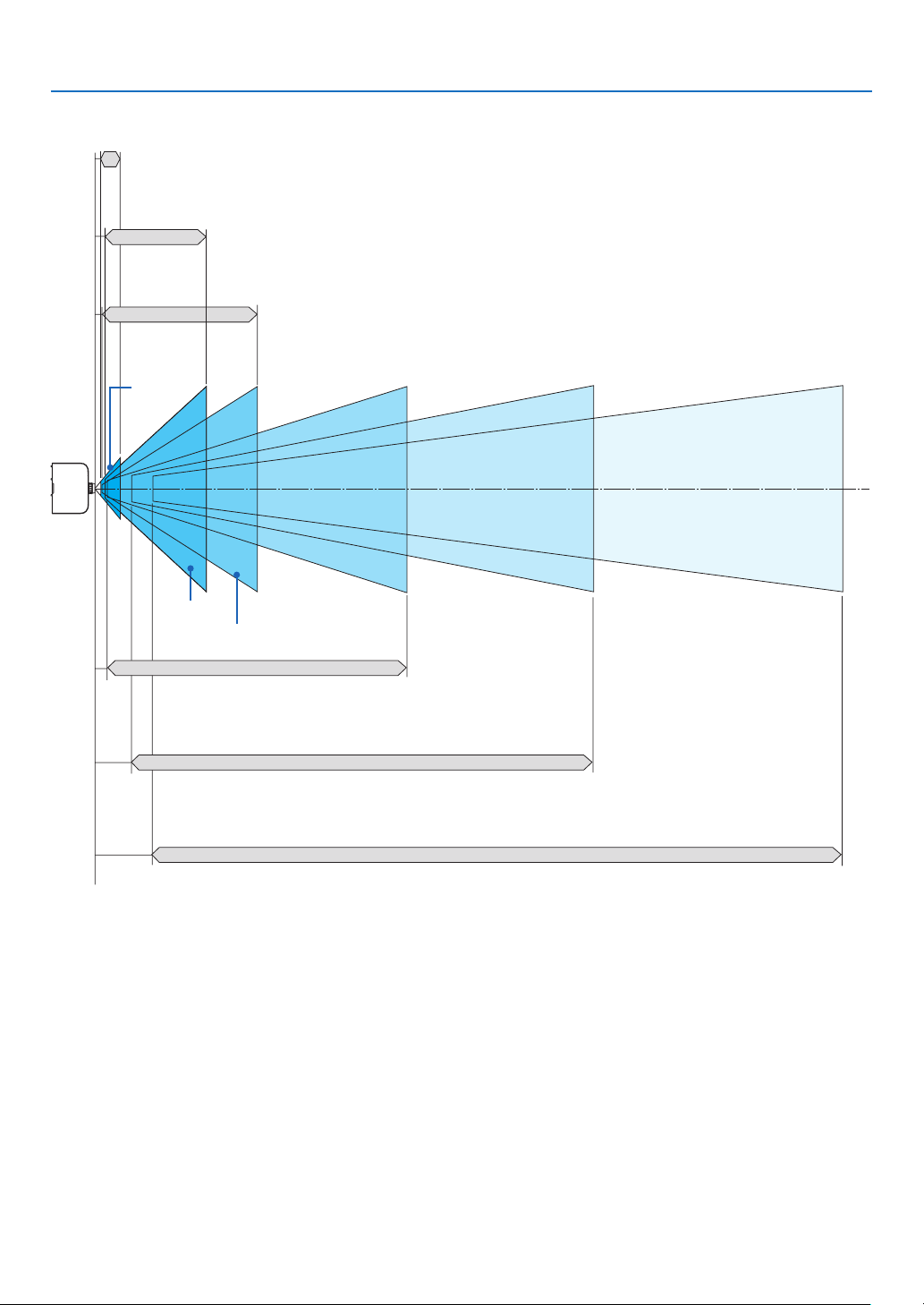
160
9. Appendix
Projection range for the different lenses
40-150"
30-500"
40-500"
60-500"
60-500"
60-500"
NP12ZL
NP14ZL
NP11FL
NP30ZL
NP-PA622U/NP-PA522U: 0.7–2.6 m
NP-PA672W/NP-PA572W: 0.7–2.6 m
NP-PA722X/NP-PA622X: 0.6–2.5 m
NP-PA622U/NP-PA522U: 1.0–11.3 m
NP-PA672W/NP-PA572W: 1.0–11.3 m
NP-PA722X/NP-PA622X: 1.0–10.9 m
NP-PA622U/NP-PA522U: 1.0–11.3 m
NP-PA672W/NP-PA572W: 1.0–11.3 m
NP-PA722X/NP-PA622X: 1.0–10.9 m
NP13ZL
NP-PA622U/NP-PA522U: 1.2–31.9 m
NP-PA672W/NP-PA572W: 1.2–32.1 m
NP-PA722X/NP-PA622X: 1.2–30.8 m
NP-PA622U/NP-PA522U: 3.7–50.9 m
NP-PA672W/NP-PA572W: 3.7–51.2 m
NP-PA722X/NP-PA622X: 3.6–49.2 m
NP15ZL
NP-PA622U/NP-PA522U: 5.9–76.4 m
NP-PA672W/NP-PA572W: 5.9–76.9 m
NP-PA722X/NP-PA622X: 5.7–73.8 m
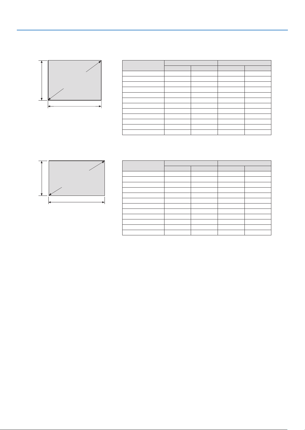
161
9. Appendix
Tables of screen sizes and dimensions
PA722X/PA622X
PA622U/PA522U/PA672W/PA572W
Screen
height
Screen
height
Screenwidth
Screenwidth
4:3screensize(di-
agonal)
16:10screensize(di-
agonal)
Size(inches) Screenwidth Screenheight
(inches) (cm) (inches) (cm)
30 24 61.0 18 45.7
40 32 81.3 24 61.0
60 48 121.9 36 91.4
80 64 162.6 48 121.9
100 80 203.2 60 152.4
120 96 243.8 72 182.9
150 120 304.8 90 228.6
200 160 406.4 120 304.8
240 192 487.7 144 365.8
300 240 609.6 180 457.2
400 320 812.8 240 609.6
500 400 1016.0 300 762.0
Size(inches) Screenwidth Screenheight
(inches) (cm) (inches) (cm)
30 25.4 64.6 15.9 40.4
40 33.9 86.2 21.2 53.8
60 50.9 129.2 31.8 80.8
80 67.8 172.3 42.4 107.7
100 84.8 215.4 53.0 134.6
120 101.8 258.5 63.6 161.5
150 127.2 323.1 79.5 201.9
200 169.6 430.8 106.0 269.2
240 203.5 516.9 127.2 323.1
300 254.4 646.2 159.0 403.9
400 339.2 861.6 212.0 538.5
500 424.0 1077.0 265.0 673.1
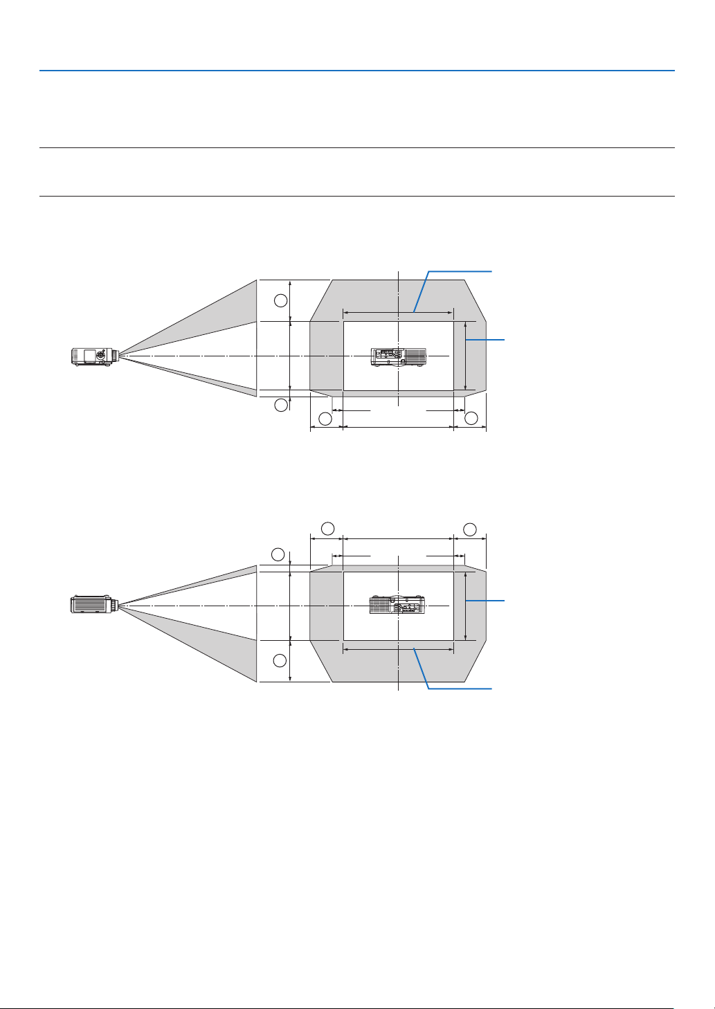
162
9. Appendix
Lens shifting range
Thisprojectorisequippedwithalensshiftfunctionforadjustingthepositionoftheprojectedimagebyturningthelens
shiftdials.Thelenscanbeshiftedwithintherangeshownbelow.
NOTE:
• ThelensshiftfunctioncannotbeusedwhenusingtheNP11FLlens.
• Pleasedonotusethelensshiftfunctionwhenprojectingportraitimages.Pleaseuseitwiththelensinthecenter.
* Refertothelensshifttableonthenextpageforthedrawingnumberofthelensshiftrange.
Desk/frontprojection
100%V
100%H
1
2
3
4
10%H 10%H
Widthofprojectedimage
Heightofprojectedimage
Descriptionofsymbols:Vindicatesvertical(heightoftheprojectedimage),Hindicateshorizontal(widthofthepro-
jectedimage).
Ceiling/frontprojector
100%V
100%H
10%H
10%H
1
2
3
4
Heightofprojectedimage
Widthofprojectedimage

163
9. Appendix
Lens shift table
Applicablemodels Drawingnumber Lensunit
NP30ZL NP12ZL NP13ZL NP14ZL NP15ZL
NP-PA622U/
NP-PA522U
①
50%V 50%V 50%V 50%V 50%V
②
10%V 10%V 10%V 10%V 10%V
③
20%H* 30%H 30%H 30%H 30%H
④
20%H* 30%H 30%H 30%H 30%H
NP-PA672W/
NP-PA572W
①
50%V 60%V 60%V 60%V 60%V
②
10%V 10%V 10%V 10%V 10%V
③
20%H 30%H 30%H 30%H 30%H
④
20%H 30%H 30%H 30%H 30%H
NP-PA722X/
NP-PA622X
①
35%V 50%V 50%V 50%V 50%V
②
10%V 10%V 10%V 10%V 10%V
③
20%H 30%H 30%H 30%H 30%H
④
20%H 30%H 30%H 30%H 30%H
* ForPA622U/PA522U,theshiftrangeinthehorizontaldirectionisupto15%Hwhenusingthelensunit“NP13ZL”toprojecta
screenexceedingModel150.
Ex.:Whenprojectingona150"screen
TheexplanationisforaPA722X/PA622Xprojector(4:3panel)withaNP12ZLlenstted.
• PleasereplacethescreendimensionsandmaximumshiftvalueinthecalculationsforthePA672W/PA572Wand
PA622U/PA522Uprojectors(16:10panel)aswell.
Accordingtothetablesofscreensizesanddimensions(→page161),H=304.8cm,V=228.6cm.
Adjustmentrangeintheverticaldirection:Theprojectedimagecanbemovedupwards0.5×228.6cm=114cm,
downwards0.1×228.6cm=22cm(whenthelensisatthecenterposition).Foraceiling/frontinstallation,theabove
guresareinverted.
Adjustmentrangeinthehorizontaldirection:Theprojectedimagecanbemovedtotheleft0.3×304.8cm=91cm,
totheright0.3×304.8cm=91cm.
*Figuresdifferbyseveral%becausethecalculationisapproximate.
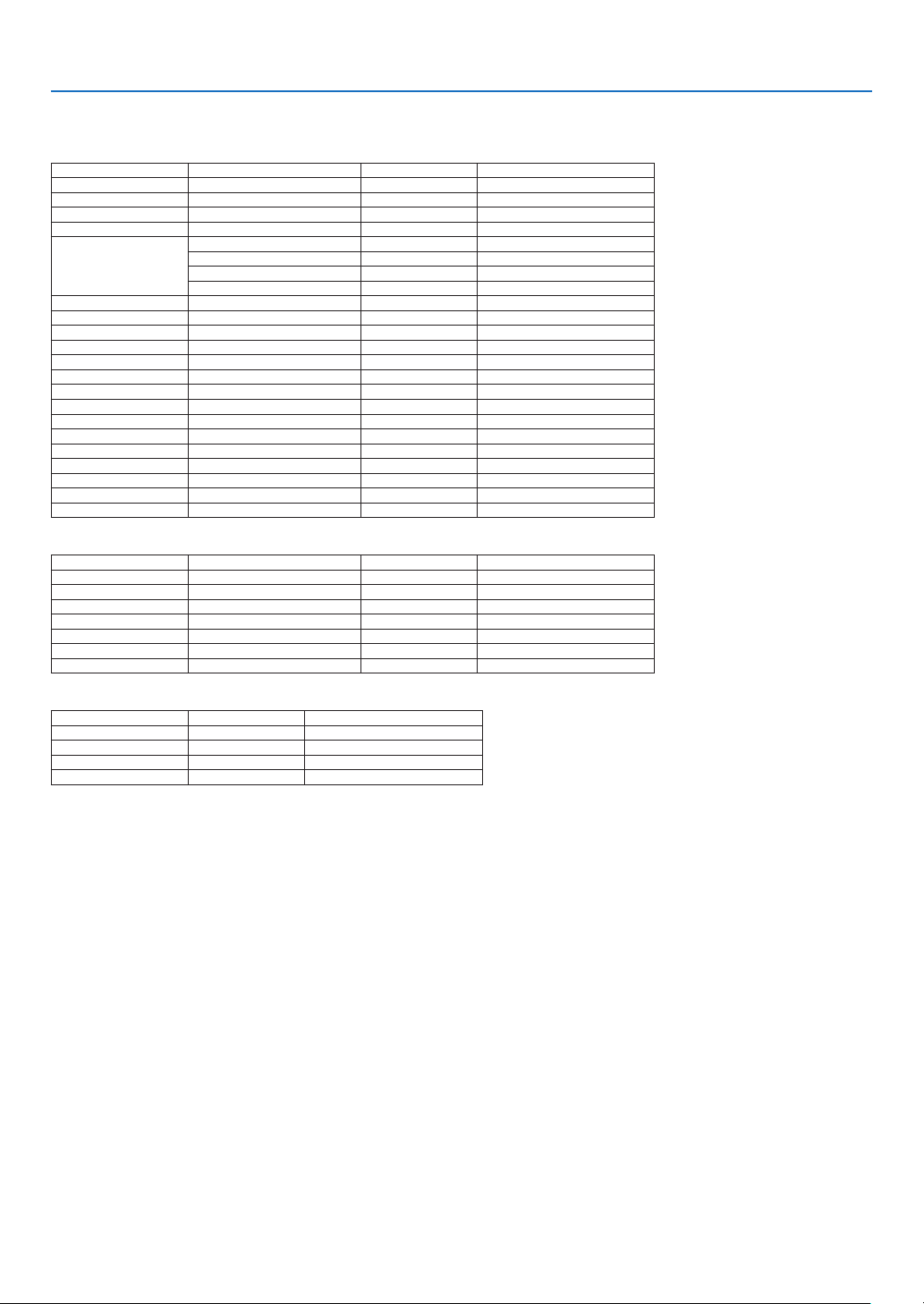
164
9. Appendix
❷ Compatible Input Signal List
Analog Computer Signal
Signal Resolution(dots) AspectRatio RefreshRate(Hz)
VGA 640 × 480 4 : 3 60/72/75/85/iMac
SVGA 800 × 600 4 : 3 56/60/72/75/85/iMac
XGA 1024 × 768 *
1
4 : 3 60/70/75/85/iMac
XGA+ 1152 × 864 4 : 3 60/70/75/85
WXGA
1280 × 768 *
2
15 : 9 60
1280 × 800 *
2
16 : 10 60
1360 × 768 *
5
16 : 9 *
4
60
1366 × 768 *
5
16 : 9 *
4
60
Quad-VGA 1280 × 960 4 : 3 60/75/85
SXGA 1280 × 1024 5 : 4 60/75/85
SXGA+ 1400 × 1050 4 : 3 60/75
WXGA+ 1440 × 900 16 : 10 60
WXGA++ 1600 × 900 16 : 9 60
UXGA 1600 × 1200 *
3
4 : 3 60/65/70/75
WSXGA+ 1680 × 1050 16 : 10 60
WUXGA
1920 × 1200 *
3
16 : 10 60(ReducedBlanking)
2K 2048 × 1080 17 : 9 60
FullHD 1920 × 1080 *
3
16 : 9 60
MAC13" 640 × 480 4 : 3 67
MAC16" 832 × 624 4 : 3 75
MAC19" 1024 × 768 4 : 3 75
MAC21" 1152 × 870 *
6
4 : 3 *
4
75
MAC23" 1280 × 1024 5 : 4 65
Component
Signal Resolution(dots) AspectRatio RefreshRate(Hz)
HDTV(1080p) 1920 × 1080 16 : 9 50/60
HDTV(1080i) 1920 × 1080 16 : 9 48/50/60
HDTV(720p) 1280 × 720 16 : 9 50/60
SDTV(480p) 720 × 480 4:3/16:9 60
SDTV(576p) 720 × 576 4:3/16:9 50
SDTV(480i) 720 × 480 4:3/16:9 60
SDTV(576i) 720 × 576 4:3/16:9 50
CompositeVideo/S-Video
Signal AspectRatio RefreshRate(Hz)
NTSC 4 : 3 60
PAL 4 : 3 50
PAL60 4 : 3 60
SECAM 4 : 3 50
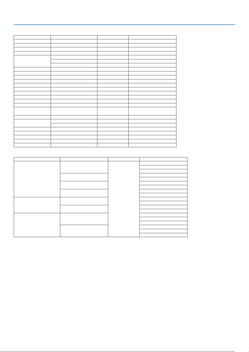
165
9. Appendix
HDMI
Signal Resolution(dots) AspectRatio RefreshRate(Hz)
VGA 640 × 480 4 : 3 60
SVGA 800 × 600 4 : 3 60
XGA 1024 × 768 *
1
4 : 3 60
HD 1280 × 720 *
2
16 : 9 60
WXGA
1280 × 768 *
2
15 : 9 60
1280 × 800 *
2
16 : 10 60
1366 × 768 *
5
16 : 9 *
4
60
Quad-VGA 1280 × 960 4 : 3 60
SXGA 1280 × 1024 5 : 4 60
SXGA+ 1400 × 1050 4 : 3 60
WXGA+ 1440 × 900 16 : 10 60
WXGA++ 1600 × 900 16 : 9 60
WSXGA+ 1680 × 1050 16 : 10 60
UXGA 1600 × 1200 *
3
4 : 3 60
FullHD 1920 × 1080 *
3
16 : 9 60
WUXGA 1920 × 1200 *
3
16 : 10 60
2K 2048 × 1080 17 : 9 60
WQHD
iMac27"
2560 × 1440 16 : 9 60
WQXGA 2560 × 1600 16 : 10
60(ReducedBlanking)
4K
3840 × 2160 16 : 9 23.98/24/25/29.97/30
4096 × 2160 17 : 9 24
HDTV(1080p) 1920 × 1080 16 : 9 24/25/30/50/60
HDTV(1080i) 1920 × 1080 16 : 9 48/50/60
HDTV(720p) 1280 × 720 16 : 9 50/60
SDTV(480i/p) 720/1440 × 480 4:3/16:9 60
SDTV(576i/p) 720/1440 × 576 4:3/16:9 50
HDMI 3D
SignalResolution(dots) RefreshRate(Hz) AspectRatio 3DFormat
1920 × 1080p
23.98/24
16 : 9
FramePacking
SideBySide
TopandBottom
25
SideBySide
TopandBottom
50
SideBySide
TopandBottom
59.94/60
SideBySide
TopandBottom
1920 × 1080i
50
TopandBottom
SideBySide
59.94/60
TopandBottom
SideBySide
1280 × 720p
50
FramePacking
SideBySide
TopandBottom
59.94/60
FramePacking
SideBySide
TopandBottom
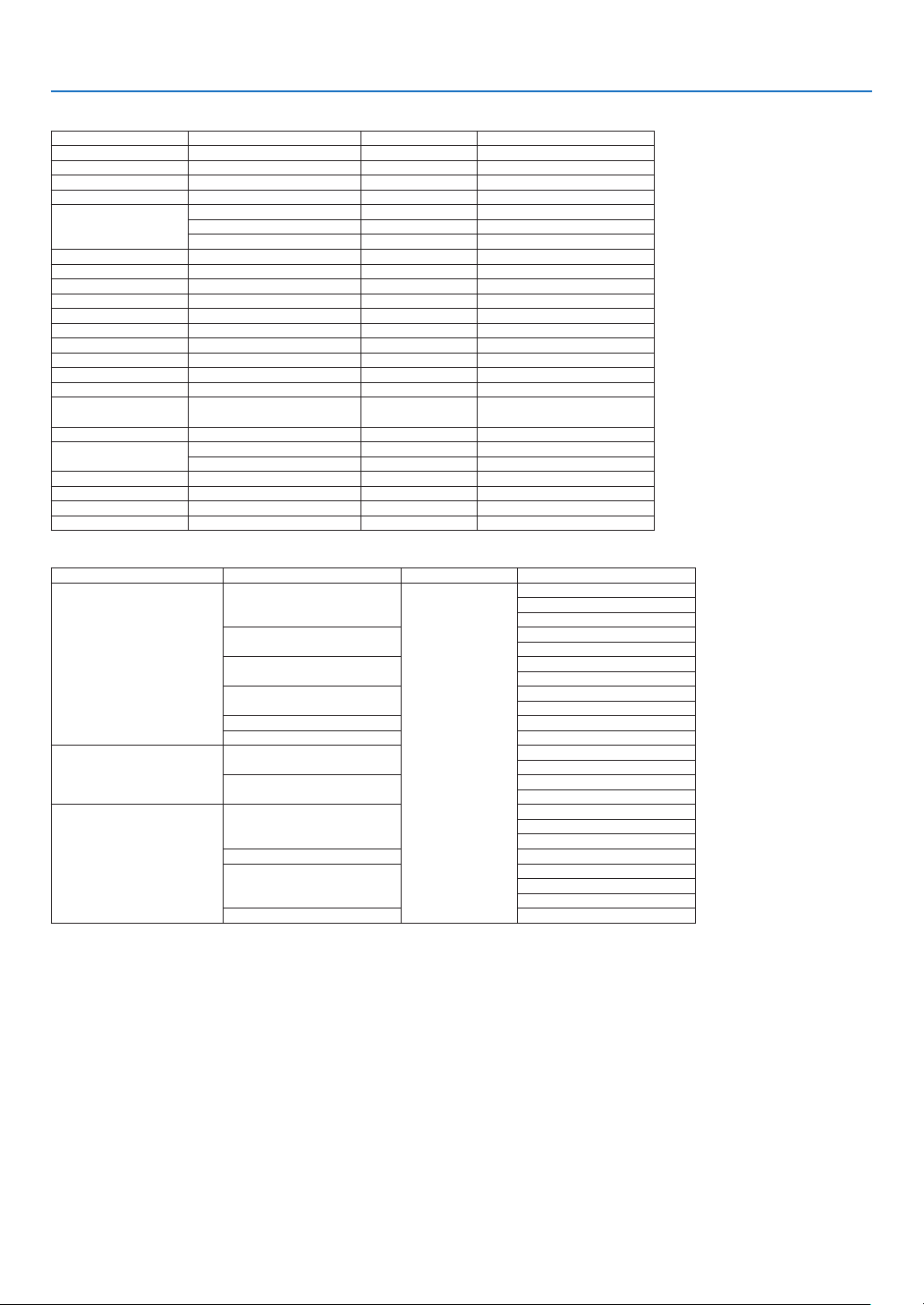
166
9. Appendix
DisplayPort
Signal Resolution(dots) AspectRatio RefreshRate(Hz)
VGA 640 × 480 4 : 3 60
SVGA 800 × 600 4 : 3 60
XGA 1024 × 768 *
1
4 : 3 60
HD 1280 × 720 *
2
16 : 9 60
WXGA
1280 × 768 *
2
15 : 9 60
1280 × 800 *
2
16 : 10 60
1366 × 768 *
5
16 : 9 *
4
60
Quad-VGA 1280 × 960 4 : 3 60
SXGA 1280 × 1024 5 : 4 60
SXGA+ 1400 × 1050 4 : 3 60
WXGA+ 1440 × 900 16 : 10 60
WXGA++ 1600 × 900 16 : 9 60
WSXGA+ 1680 × 1050 16 : 10 60
UXGA 1600 × 1200 *
3
4 : 3 60
FullHD 1920 × 1080 *
3
16 : 9 60
WUXGA 1920 × 1200 *
3
16 : 10 60(ReducedBlanking)
2K 2048 × 1080 17 : 9 60
WQHD
iMac27"
2560 × 1440 16 : 9 60
WQXGA 2560 × 1600 16 : 10
60(ReducedBlanking)
4K
3840 × 2160 16 : 9 23.98/24/25/29.97/30
4096 × 2160 17 : 9 24
HDTV(1080p) 1920 × 1080 16 : 9 24/25/30/50/60
HDTV(720p) 1280 × 720 16 : 9 50/60
SDTV(480i/p) 720/1440 × 480 4:3/16:9 60
SDTV(576i/p) 720/1440 × 576 4:3/16:9 50
DisplayPort3D
SignalResolution(dots) RefreshRate(Hz) AspectRatio 3DFormat
1920 × 1080p
23.98/24
16 : 9
FramePacking
SideBySide
TopandBottom
25
SideBySide
TopandBottom
50
SideBySide
TopandBottom
59.94/60
SideBySide
TopandBottom
100 FrameSequential
120 FrameSequential
1920 × 1080i
50
TopandBottom
SideBySide
59.94/60
TopandBottom
SideBySide
1280 × 720p
50
FramePacking
SideBySide
TopandBottom
100 FrameSequential
59.94/60
FramePacking
SideBySide
TopandBottom
120 FrameSequential
*1 NativeresolutiononXGAmodel(PA722X/PA622X)
*2 NativeresolutiononWXGAmodel(PA672W/PA572W)
*3 NativeresolutiononWUXGAmodel(PA622U/PA522U)
*4 ApproximateValue
*5 Theprojectormayfailtodisplaythesesignalscorrectlywhen[AUTO]isselectedfor[ASPECTRATIO]intheon-screenmenu.
Thefactorydefaultis[AUTO]for[ASPECTRATIO].Todisplaythesesignals,select[16:9]for[ASPECTRATIO].
*6 Theprojectormayfailtodisplaythesesignalscorrectlywhen[AUTO]isselectedfor[ASPECTRATIO]intheon-screenmenu.
Thefactorydefaultis[AUTO]for[ASPECTRATIO].Todisplaythesesignals,select[4:3]for[ASPECTRATIO].
• Signalsexceedingtheprojector’sresolutionarehandledwithAdvancedAccuBlend.
• WithAdvancedAccuBlend,thesizeofcharactersandruledlinesmaybeunevenandcolorsmaybeblurred.
• Uponshipment,theprojectorissetforsignalswithstandarddisplayresolutionsandfrequencies,butadjustmentsmayberequired
dependingonthetypeofcomputer.
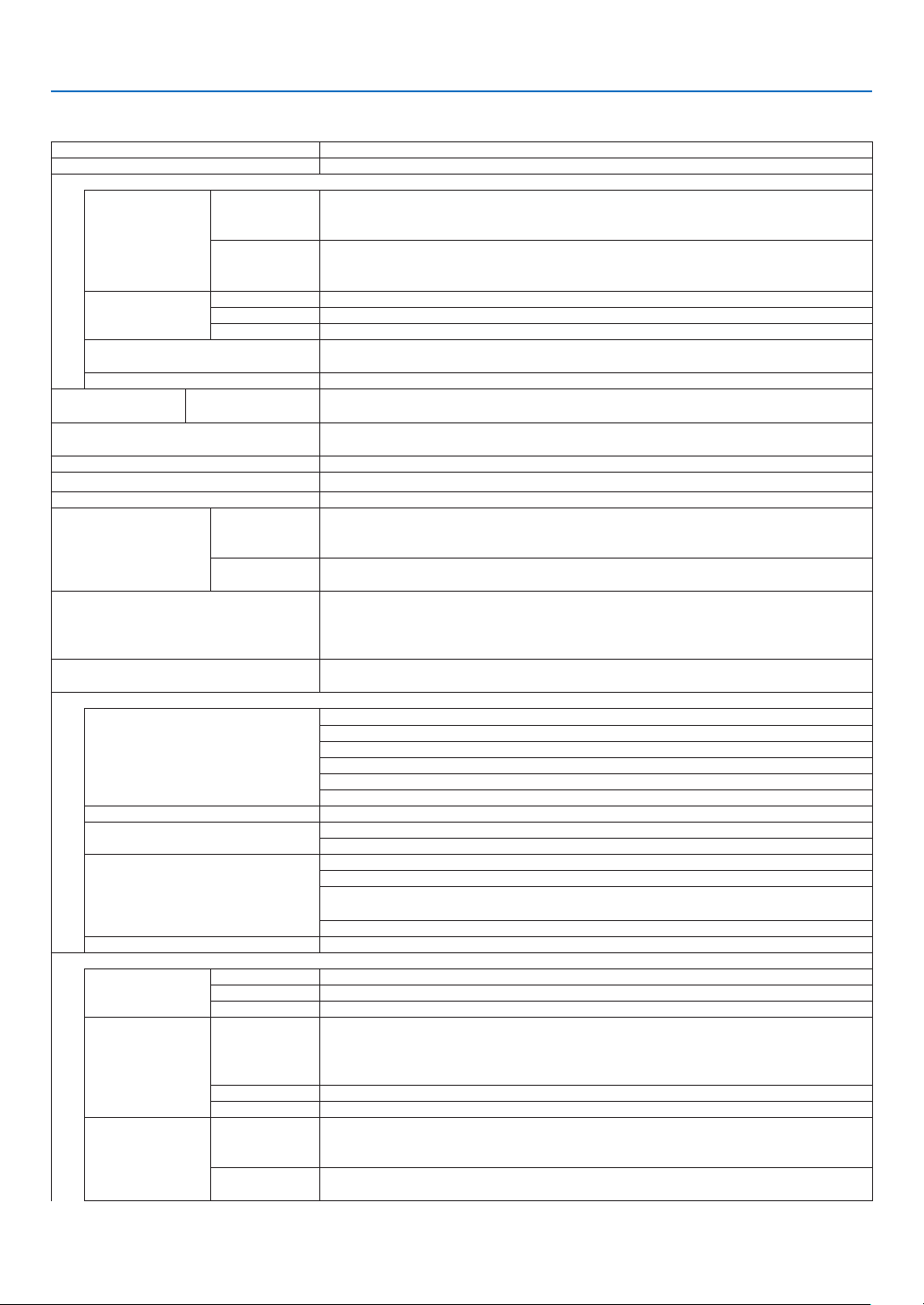
167
9. Appendix
❸ Specifications
Modelname PA622U/PA522U/PA672W/PA572W/PA722X/PA622X
Method
Threeprimarycolorliquidcrystalshutterprojectionmethod
Specicationsofmainparts
Liquidcrystal
panel
Size PA722X/PA622X:0.79"(withMLA)×3(aspectratio:4:3)
PA672W/PA572W:0.76"(withMLA)×3(aspectratio:16:10)
PA622U/PA522U:0.76"(withMLA)×3(aspectratio:16:10)
Pixels
(*1)
PA722X/PA622X:786,432(1024dots×768lines)
PA672W/PA572W:1,024,000(1280dots×800lines)
PA622U/PA522U:2,304,000(1920dots×1200lines)
Projectionlenses Zoom Manual(zoomrangedependsonlens)
Focus Manual
Lensshifting Manual
Lightsource PA722X/PA672W/PA622U:350WAClamp(264WwhenEcomodeison)
PA622X/PA572W/PA522U:330WAClamp(264WwhenEcomodeison)
Opticaldevice Opticalisolationbydichroicmirror,combiningbydichroicprism
Lightoutput
(*2)
(*3)
ECOOFF PA722X:7200lm,PA622X:6200lm,PA672W:6700lm,PA572W:5700lm,PA622U:
6200lm,PA522U:5200lm
Contrastratio
(*2)
(allwhite/allblack) PA722X/PA672W/PA622U:6000:1
PA622X/PA572W/PA522U:5000:1
Screensize(throwdistance) 30"to500"(throwdistancedependsonlens)
Colorreproducibility 10-bitcolorprocessing(approx.1.07billioncolors)
(*4)
Audiooutput Built-in10Wmonauralspeaker
Scanningfrequency Horizontal Analog:15kHz,24to100kHz(24kHzorgreaterforRGBinputs),conformingto
VESAstandards
Digital:15kHz,24to153kHz,conformingtoVESAstandards
Vertical Analog:48Hz,50to85Hz,100,120HzconformingtoVESAstandards
Digital:24,25,30,48Hz,50to85Hz,100,120HzconformingtoVESAstandards
Mainadjustmentfunctions Manualzoom,manualfocus,manuallensshift,inputsignalswitching(HDMI1/HDMI2/
DisplayPort/BNC/BNC(CV)/BNC(Y/C)/COMPUTER/HDBaseT),autoimageadjust-
ment,pictureenlarging,picturepositionadjustment,muting(bothvideoandaudio),
poweron/standby,on-screendisplay/selection,etc.
Max.displayresolution(horizontal×
vertical)
Analog:1920×1200(handledwithAdvancedAccuBlend)
Digital:4096×2160(handledwithAdvancedAccuBlend)
Inputsignals
R,G,B,H,V RGB:0.7Vp-p/75Ω
Y:1.0Vp-p/75Ω(withNegativePolaritySync)
Cb,Cr(Pb,Pr):0.7Vp-p/75Ω
H/VSync:4.0Vp-p/TTL
CompositeSync:4.0Vp-p/TTL
SynconG:1.0Vp-p/75Ω(withSync)
Compositevideo 1.0Vp-p/75Ω
S-Video
Y:1.0Vp-p/75Ω
C:286Vp-p/75Ω
Component
Y:1.0Vp-p/75Ω(withSync)
Cb,Cr(Pb,Pr):0.7Vp-p/75Ω
DTV:480i,480p,720p,1080i,1080p(60Hz)
576i,576p,720p,1080i(50Hz)
DVD:Progressivesignal(50/60Hz)
Audio 0.5Vrms/22kΩorgreater
Input/outputconnectors
Computer/Com-
ponent
Videoinput MiniD-Sub15-pin×1,BNCconnector×5
Audioinput Stereominijack×2
Audiooutput Stereominijack×1(commonforallsignals)
HDMI Videoinput HDMI
®
ConnectortypeA×2
DeepColor(colordepth):8-/10-/12-bitcompatible
Colorimetry:RGB,YcbCr444andYcbCr422compatible
LipSynccompatible,HDCPcompatible
(*5)
,Supports4Kand3D
Videooutput Repeater
Audioinput HDMI:Samplingfrequency–32/44.1/48kHz,Samplingbits–16/20/24bits
HDBaseT Videoinput DeepColor(colordepth):Support8/10/12bits
Colorimetry:SupportRGB,YCbCr444andYCbCr422
SupportLipSync,HDCP
(*5)
,4K,3D
Audioinput Samplingfrequency:32/44.1/48kHz
Samplingbit:16/20/24bit
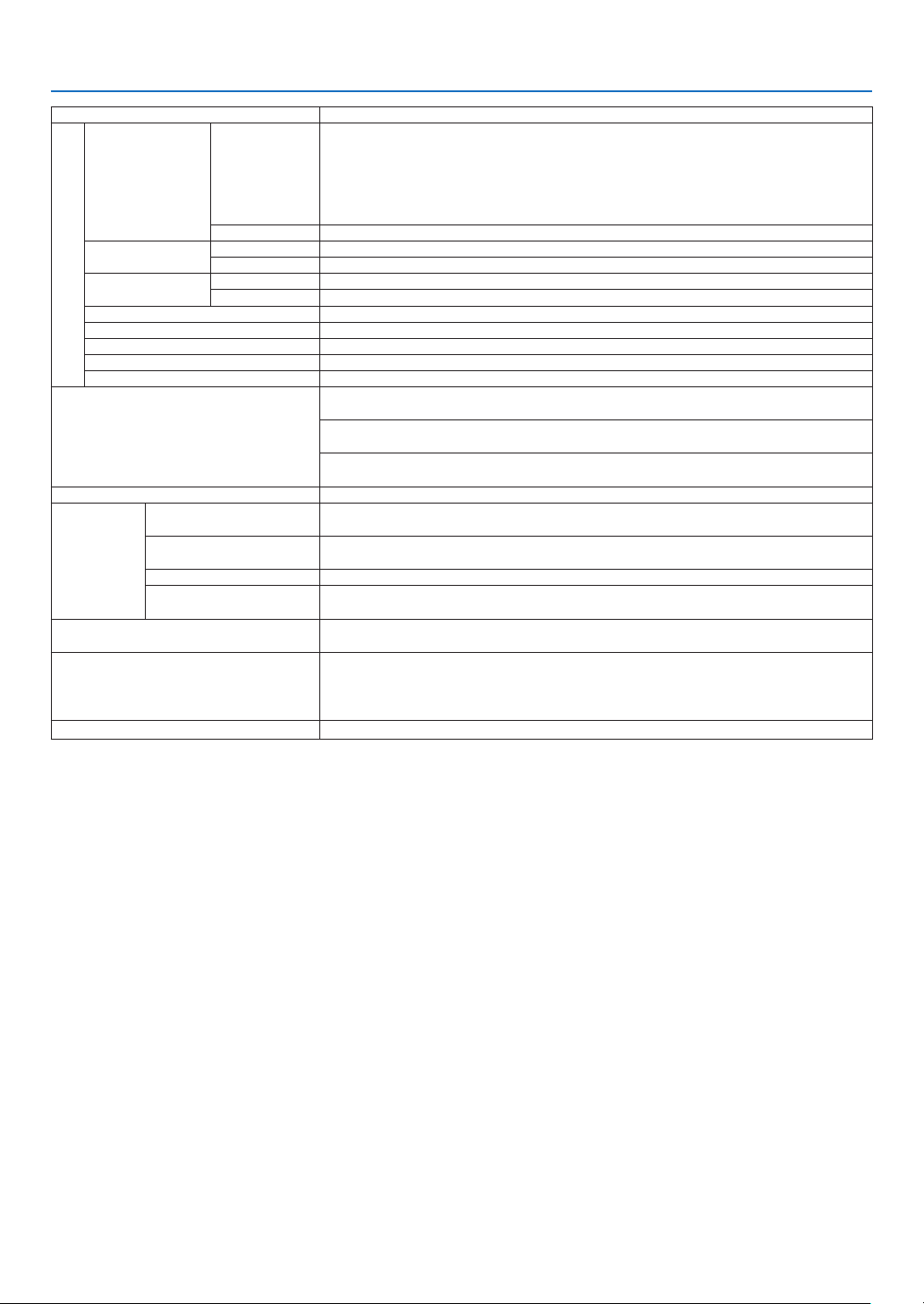
168
9. Appendix
Modelname PA622U/PA522U/PA672W/PA572W/PA722X/PA622X
DisplayPort
Videoinput DisplayPort×1
Datarate:2.7Gbps/1.62Gbps
No.lanes:1lane/2lanes/4lanes
Colordepth:6-bit,8-bit,10-bit
Colorimetry:RGB,YcbCr444andYcbCr422compatible
HDCPcompatible
(*5)
Audioinput DisplayPort:Samplingfrequency–32/44.1/48kHz,Samplingbits–16/20/24bits
BNC(CV) Videoinput BNC×1
Audioinput (sharedwiththeBNC,BNC(CV),BNC(Y/C)audioinputterminals)
BNC(Y/C) Videoinput BNC×2
Audioinput (sharedwiththeBNC,BNC(CV),BNC(Y/C)audioinputterminals)
PCcontrolconnector D-Sub9-pin×1
USBport USBtypeA×1
Ethernet/HDBaseTport RJ-45×1,SupportsBASE-TX
Remoteconnector Stereominijack×1
3DSYNCoutputterminal 5V/10mA,synchronizedsignaloutputfor3Duse
Usageenvironment Operatingtemperature:5to40ºC
(*6)
Operatinghumidity:20to80%(withnocondensation)
Storagetemperature:-10to50ºC
(*6)
Storagehumidity:20to80%(withnocondensation)
Operatingaltitude:0to2700m/8800feet
(1700to2700m/5500to8800feet:Set[FANMODE]to[HIGHALUTITUDE])
Powersupply 100-240VAC,50/60Hz
Powercon-
sumption
Ecomodeoff PA722X/PA672W/PA622U:483W(100-130V)/460W(200-240V)
PA622X/PA572W/PA522U:463W(100-130V)/440W(200-240V)
Ecomodeon PA722X/PA672W/PA622U/PA622X/PA572W/PA522U:377W(100-130V)/362W(200-
240V)
STANDBY(NORAML) 0.11 W
STANDBY(HDBaseT
STANDBY)
7.0 W
Ratedinputcurrent PA722X/PA672W/PA622U:5.5A-2.2A
PA622X/PA572W/PA522U:5.1A-2.2A
Externaldimensions 19.7"(width)×5.68"(height)×14.1"(depth)/499(width)×142(height)×359(depth)
mm(notincludingprotrudingparts)
19.7"(width)×6.38"(height)×14.5"(depth)/499(width)×162(height)×368(depth)
mm(includingprotrudingparts)
Weight 18.5lbs/8.4kg(notincludinglens)
*1 Effectivepixelsaremorethan99.99%.
*2 Thisisthelightoutputvalue(lumens)whenthe[PRESET]modeissetto[HIGH-BRIGHT].Thelightoutputvalueswilldropto
80%when[ON]isselectedfor[ECOMODE].Ifanyothermodeisselectedasthe[PRESET]mode,thelightoutputvaluemay
dropslightly.
*3 CompliancewithISO21118-2005
*4 Fullcolor(approx.16.77millioncolorsorgreater)whentheHDBaseTinputconnectorisselected.
*5 HDMI
®
(DeepColor,LipSync)withHDCP
WhatisHDCP/HDCPtechnology?
HDCPisanacronymforHigh-bandwidthDigitalContentProtection.HighbandwidthDigitalContentProtection(HDCP)isasystem
forpreventingillegalcopyingofvideodatasentoveraHigh-DenitionMultimediaInterface(HDMI).
IfyouareunabletoviewmaterialviatheHDMIinput,thisdoesnotnecessarilymeantheprojectorisnotfunctioningproperly.With
theimplementationofHDCP,theremaybecasesinwhichcertaincontentisprotectedwithHDCPandmightnotbedisplayed
duetothedecision/intentionoftheHDCPcommunity(DigitalContentProtection,LLC).
Video:DeepColor;8/10/12-bit,LipSync
Audio:LPCM;upto2ch,samplerate32/44.1/48KHz,samplebit;16/20/24-bit
*6 35to40ºC–“Forcedecomode”
(PA622U/PA522Uwillshifttotheeco-modeinstagesstartingfrom33°C.)
• Thesespecicationsandtheproduct’sdesignaresubjecttochangewithoutnotice.
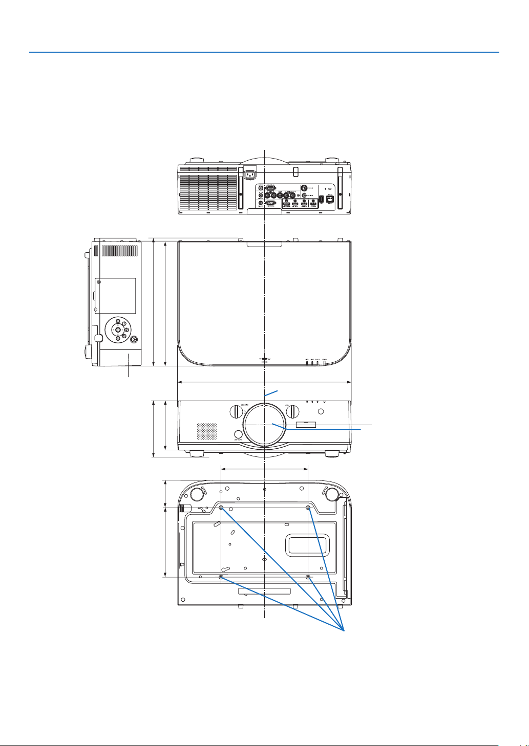
169
9. Appendix
250 (9.8)
162 (6.4)
359 (14.1)
368 (14.5)
78.5 (3.1)
142 (5.6)
200 (7.9)
499 (19.6)
❹ Cabinet Dimensions
Lenscenter
Lenscenter
Holesforceilingmount
Unit:mm(inch)
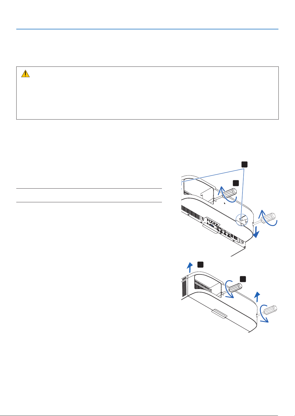
170
9. Appendix
❺ Mounting the cable cover (sold separately)
Mountingtheseparatelysoldcablecover(NP04CV)ontheprojectorallowsyouhidethecablesforacleaner
appearance.
CAUTION
• Aftermountingthecablecover,besuretofastenusingthescrewsprovided.Ifnot,thecablecovercouldfall,
damagingthecablecoverandpossiblyresultingininjury.
• Donotbundlethepowercordandplaceitunderthecablecover.Doingsocouldleadtore.
• Donot applyexcessiveforceto thecablecover.Doingso coulddamagethecablecover,resultingin the
projectorfallingorcausinginjury.
Mounting
Preparations:
1. Connectthepowercordandcablestotheprojector(theconnectioncordsareomittedfromthediagrams).
2. PrepareaPhillipsscrewdriver.
1. Insert the two round protrusions on the left and right edges
of the cable cover into the grooves in the bottom of the
projector to line it up.
NOTE:Becarefulnottoletthepowercordandcablesgetpinchedbythe
cable cover.
2. Turn the cable cover screw clockwise.
• Tightenthescrewsecurely.
1
2
Removing
1. Turn the cable cover screw counterclockwise until it turns
loosely.
• Holdthecablecoverwhiledoingthistopreventitfromfall-
ing.
• Thescrewdoesnotcomecompletelyoff.
2. Remove the cable cover.
• Turnthecablecoveralittle,thenliftitoff.
1
2
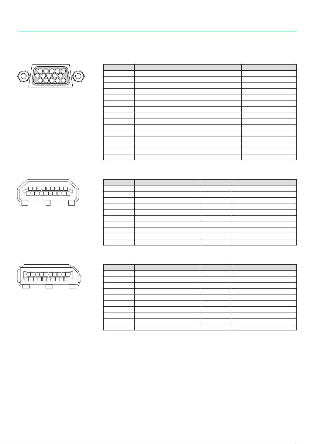
171
9. Appendix
❻ Pin assignments and signal names of main connectors
COMPUTER IN/ Component Input Connector (Mini D-Sub 15 Pin)
Connection and signal level of each pin
51423
10
11 12 13 14 15
6978
Signal Level
Videosignal:0.7Vp-p(Analog)
Syncsignal:TTLlevel
Pin No. RGBSignal(Analog) YCbCr Signal
1 Red Cr
2 GreenorSynconGreen Y
3 Blue Cb
4 Ground
5 Ground
6 RedGround CrGround
7 GreenGround YGround
8 BlueGround CbGround
9 NoConnection
10 SyncSignalGround
11 NoConnection
12 Bi-directionalDATA(SDA)
13 HorizontalSyncorCompositeSync
14 VerticalSync
15 DataClock
HDMI 1 IN/HDMI 2 IN Connector (Type A)
135791113151719
246810 12 14 16 18
Pin No. Signal Pin No. Signal
1 TMDSData2+ 11 TMDSClockShield
2 TMDSData2Shield 12 TMDSClock−
3 TMDSData2− 13 CEC
4 TMDSData1+ 14 Disconnection
5 TMDSData1Shield 15 SCL
6 TMDSData1− 16 SDA
7 TMDSData0+ 17 DDC/CECgrounding
8 TMDSData0Shield 18 +5Vpowersupply
9 TMDSData0− 19 Hotplugdetection
10 TMDSClock+
DisplayPort IN Connector
135791113151719
246810 12 14 16 18 20
Pin No. Signal Pin No. Signal
1 Mainlinklane3− 11 Grounding0
2 Grounding3 12 Mainlinklane0+
3 Mainlinklane3+ 13 Conguration1
4 Mainlinklane2− 14 Conguration2
5 Grounding2 15 Supplementarychannel+
6 Mainlinklane2+ 16 Grounding4
7 Mainlinklane1− 17 Supplementarychannel−
8 Grounding1 18 Hotplugdetection
9 Mainlinklane1+ 19 Return
10 Mainlinklane0− 20 +3.3Vpowersupply
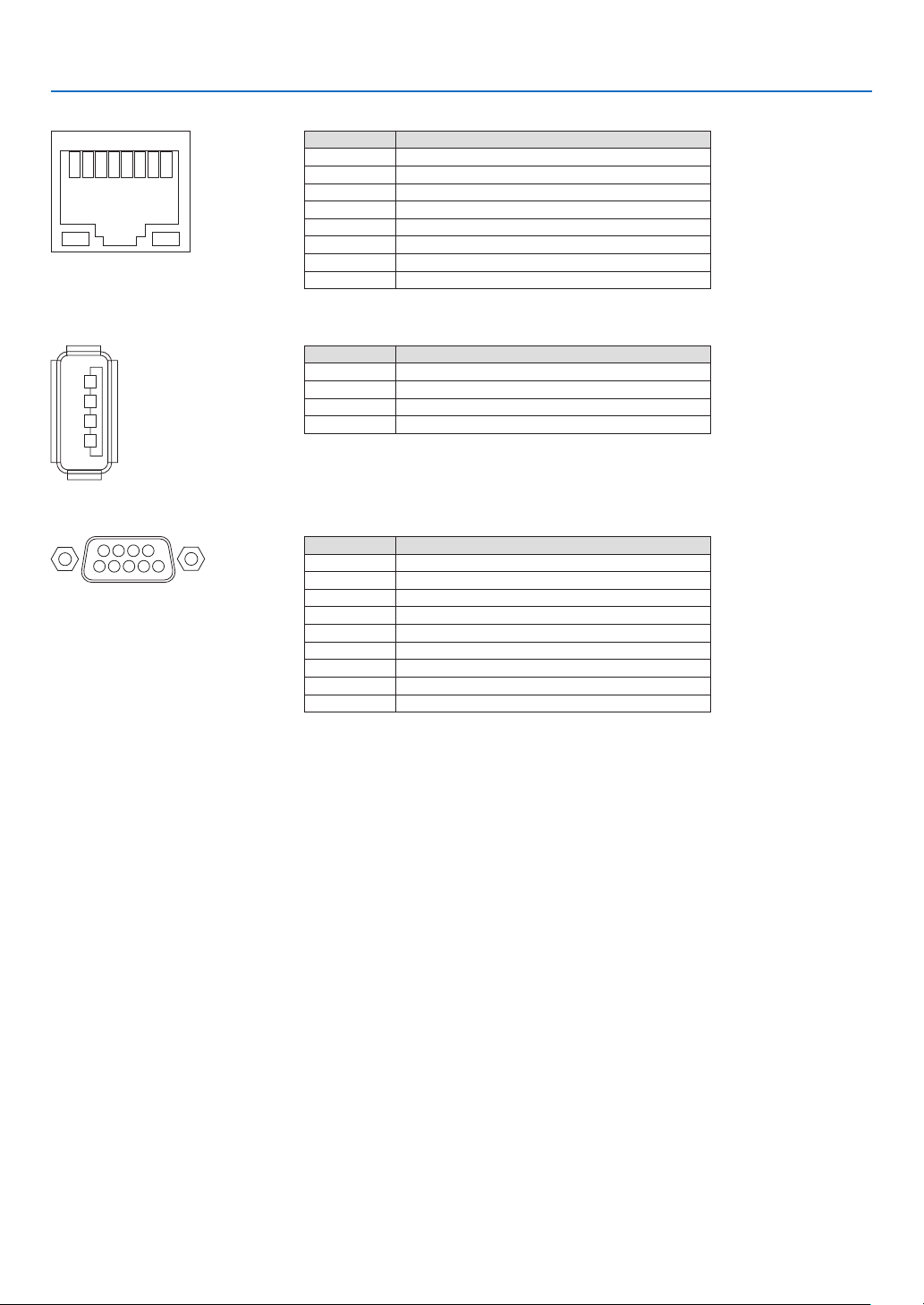
172
9. Appendix
Ethernet/HDBase T Port (RJ-45)
12345678
Pin No. Signal
1 TxD+/HDBT0+
2 TxD−/HDBT0−
3 RxD+/HDBT1+
4 Disconnection/HDBT2+
5 Disconnection/HDBT2−
6 RxD−/HDBT1−
7 Disconnection/HDBT3+
8 Disconnection/HDBT3−
USB-A Port (Type A)
1
3
2
4
Pin No. Signal
1 V
BUS
2 D−
3 D+
4 Grounding
PC CONTROL Port (D-Sub 9 Pin)
1234
5
6789
Communications protocol
Pin No. Signal
1 Unused
2 RxD receptiondata
3 TxD transmissiondata
4 Unused
5 Grounding
6 Unused
7 RTS transmissionrequest
8 CTS transmissionallowed
9 Unused

173
9. Appendix
❼ Troubleshooting
Thissectionhelpsyouresolveproblemsyoumayencounterwhilesettinguporusingtheprojector.
Indicator Messages
Power Indicator
Indicatordisplay Projectorstatus Procedure
Off Powerisoff. –
Flashing
Blue(shortashes) Preparingtoturnpoweron Waitawhile.
Blue(longashes) Offtimer(enabled)
Programtimer(offtimeenabled)
–
Orange(short
ashes)
Projectorcooling Waitawhile.
Orange(longashes) Programtimer(ontimeenabled)
Lit Blue Poweron –
Red Standbymode(NORMAL) –
Orange
Standbymode(HDBaseTSTANDBY) –
Status Indicator
Indicatordisplay Projectorstatus Procedure
Off
Noproblem,or
standbymode
–
Flashing
Red(cycles
of1)
Coverproblem Thelampcoverisnotproperlymounted.Mountitproperly.(→
Page144)
Red(cycles
of4)
Fanproblem Thecoolingfanhasstoppedturning.ContactanNECprojector
customersupportcenterforrepairs.
Flashing Orange Networkconict It is not possible to connect the projector’s built-in LAN and
wirelessLANsimultaneouslytothesamenetwork.Toconnect
theprojector’sbuilt-inLAN andwirelessLANsimultaneously,
connectthemtodifferentnetworks.
Lit Green STANDBYMODEin
sleepmode*
–
Orange
Buttonhasbeen
pressedwhileprojec-
torisinkeylockmode
Theprojector’skeysarelocked.Thesettingmustbecanceled
tooperatetheprojector.(→Page104)
Projector’sIDnumber
andremotecontrol’s
IDnumberdonot
match
CheckthecontrolIDs.(→Pages105)
* Sleepmodereferstothestatewherebythefunctionalrestrictionsduetothestandbymodesettingareremoved.

174
9. Appendix
Lamp Indicator
Indicatordisplay Projectorstatus Procedure
Off
Thelampisturnedoff. –
Flashing Green
Preparingtorelightlampafter
lightinghasfailed
Waitawhile.
Red Lampreplacementgrace
period
Thelamphasreachedtheendofitsservicelifeandis
nowinthereplacementgraceperiod(100hours).Re-
placethelampassoonaspossible.(→page142)
Red(cycles
of6)
Lampdoesnotlight Thelamphasnotturnedon.Waitatleast1minute,then
turnthepowerbackon.Ifthelampstilldoesnotlight,
contactanNECprojectorcustomersupportcenter.
Lit Red Lampusagetimeexceeded Thelamphasexceededitsusagetime.Theprojector’s
powercannotbeturnedonuntilthelampisreplaced.
(→page142)
Green
Lamplit –
Temp. Indicator
Indicatordisplay Projectorstatus Procedure
Off
Noproblem
Flashing Red(cyclesof2) Temperatureproblem The temperature protector has been activated. If the
roomtemperatureishigh,movetheprojectortoacool
place.Iftheproblemstillpersists,contactanNECprojec-
torcustomersupportcenter.
Lit Orange Highsurroundingtemperature Thesurroundingtemperatureishigh.Lowertheroom
temperature.
If the temperature protector is activated
Iftheprojector’sinternaltemperaturerisesabnormally,thelampturnsoffandthetemperatureindicatorashes(re-
peatedlyincyclesof2).
Itmayhappenthattheprojector’stemperatureprotectorissimultaneouslyactivatedandtheprojector’spowerturns
off.
Ifthishappens,dothefollowing:
- Unplugthepowercordfromthepoweroutlet.
- Ifusinginaplacewherethesurroundingtemperatureishigh,movetheprojectortoadifferent,coolplace.
- Ifthereisdustintheventilationholes,clean.(→pages138and141)
- Waitassuchabout1hourfortheprojector’sinternaltemperaturetolower.

175
9. Appendix
Common Problems & Solutions
(→“Power/Status/LampIndicator”onpage174.)
Problem CheckTheseItems
Does not turn on
or shut down
• Checkthatthepowercordispluggedinandthatthepowerbuttonontheprojectorcabinetortheremotecontrol
is on� (→ pages 13, 14)
• Ensurethatthelampcoverisinstalledcorrectly.(→ page 144)
• Checktoseeiftheprojectorhasoverheated.Ifthereisinsufcientventilationaroundtheprojectororiftheroom
where you are presenting is particularly warm, move the projector to a cooler location�
• Checktoseeifyoucontinuetousetheprojectorforanother100hoursafterthelamphasreachedtheendofits
life� If so, replace the lamp� After replacing the lamp, reset the lamp hours used� (→ page 116)
• Thelampmayfailtolight.Waitafullminuteandthenturnonthepoweragain.
• Set[FANMODE]to[HIGHALTITUDE]whenusingtheprojectorataltitudesapproximately5500feet/1600meters
or higher� Using the projector at altitudes approximately 5500 feet/1600 meters or higher without setting to [HIGH
ALTITUDE] can cause the projector to overheat and the projector could shut down� If this happens, wait a couple
minutes and turn on the projector� (→ page 97)
If you turn on the projector immediately after the lamp is turned off, the fans run without displaying an image for
some time and then the projector will display the image� Wait for a moment�
Will turn off • Ensurethatthe[OFFTIMER],[AUTOPOWEROFF]or[PROGRAMTIMER]isoff.(→ page 100, 115)
No picture
• Checkiftheappropriateinputisselected.(→ page 16) If there is still no picture, press the INPUT button or one
of the input buttons again�
• Ensureyourcablesareconnectedproperly.
• Usemenustoadjustthebrightnessandcontrast.(→ page 76)
• Ensurethatthelenscoverisopen.(→ page 14)
• Resetthesettingsoradjustmentstofactorypresetlevelsusingthe[RESET]intheMenu.(→ page 116)
• EnteryourregisteredkeywordiftheSecurityfunctionisenabled.(→ page 36)
• IftheHDMIinputortheDisplayPortsignalcannotbedisplayed,trythefollowing.
- Reinstall your driver for the graphics card built in your computer, or use the updated driver�
For reinstalling or updating your driver, refer to the user guide accompanied with your computer or graphics
card, or contact the support center for your computer manufacturer�
Install the updated driver or OS on your own responsibility�
We are not liable for any trouble and failure caused by this installation�
• SignalsmaynotbesupporteddependingontheHDBaseTtransmissiondevice.IRandRS232Ccannotbeused
in certain cases as well�
• BesuretoconnecttheprojectorandnotebookPCwhiletheprojectorisinstandbymodeandbeforeturningon
the power to the notebook PC�
In most cases the output signal from the notebook PC is not turned on unless connected to the projector before
being powered up�
* If the screen goes blank while using your remote control, it may be the result of the computer’s screen-saver
or power management software�
• Seealsothepage177�
Picture suddenly
becomes dark
• CheckiftheprojectorisintheForcedECOmodebecauseoftoohighambienttemperature.Ifthisisthecase,
lower the internal temperature of the projector by selecting [HIGH] for [FAN MODE]� (→ page 97)
Color tone or hue is
unusual
• Checkifanappropriatecolorisselectedin[WALLCOLOR].Ifso,selectanappropriateoption.(→ page 97)
• Adjust[HUE]in[PICTURE].(→ page 77)
Image isn’t square to
the screen
• Repositiontheprojectortoimproveitsangletothescreen.(→ page 18)
• UsetheKeystonecorrectionfunctiontocorrectthetrapezoiddistortion.(→ page 33)
Picture is blurred
• Adjustthefocus.(→ page 20)
• Repositiontheprojectortoimproveitsangletothescreen.(→ page 18)
• Ensure that the distance between the projector and screen is within the adjustment range of the lens.
(→ page 158)
• Hasthelensbeenshiftedbyanamountexceedingtheguaranteedrange?(→ page 162)
• Condensationmayformonthelensiftheprojectoriscold,broughtintoawarmplaceandisthenturnedon.
Should this happen, let the projector stand until there is no condensation on the lens�
Flicker appears on
screen
• Set[FANMODE]tootherthan[HIGHALTITUDE]modewhenusingtheprojectorataltitudesapproximately5500
feet/1600 meters or lower� Using the projector at altitudes less than approximately 5500 feet/1600 meters and
setting to [HIGH ALTITUDE] can cause the lamp to overcool, causing the image to flicker� Switch [FAN MODE] to
[AUTO]� (→ page 97)
Image is scrolling
vertically, horizontally
or both
• Checkthecomputer’sresolutionandfrequency.Makesurethattheresolutionyouaretryingtodisplayissupported
by the projector� (→ page 164)
• AdjustthecomputerimagemanuallywiththeHorizontal/Verticalinthe[IMAGEOPTIONS].(→ page 79)

176
9. Appendix
Problem CheckTheseItems
Remote control does
not work
• Installnewbatteries.(→ page 10)
• Makesuretherearenoobstaclesbetweenyouandtheprojector.
• Standwithin22feet(7m)oftheprojector.(→ page 11)
• Toperformcomputermouseoperationsusingtheprojector’sremotecontrol,connecttheoptionalmousereceiver
to the computer� (→ page 31)
Indicator is lit or
blinking
• SeethePOWER/STATUS/LAMPIndicator.(→ page 173)
Cross color in RGB
mode
• PresstheAUTOADJ.buttonontheprojectorcabinetortheremotecontrol.(→ page 24)
• Adjustthecomputerimagemanuallywith[CLOCK]/[PHASE]in[IMAGEOPTIONS]inthemenu.(→ page 78)
Formoreinformationcontactyourdealer.

177
9. Appendix
If there is no picture, or the picture is not displayed correctly.
• PoweronprocessfortheprojectorandthePC.
BesuretoconnecttheprojectorandnotebookPCwhiletheprojectorisinstandbymodeandbeforeturningon
thepowertothenotebookPC.
InmostcasestheoutputsignalfromthenotebookPCisnotturnedonunlessconnectedtotheprojectorbefore
beingpoweredup.
NOTE:Youcancheckthehorizontalfrequencyofthecurrentsignalintheprojector’smenuunderInformation.Ifitreads“0kHz”,
this means there is no signal being output from the computer. (→ page 119 or go to next step)
• Enablingthecomputer’sexternaldisplay.
DisplayinganimageonthenotebookPC’sscreendoesnotnecessarilymeanitoutputsasignaltotheprojector.
WhenusingaPCcompatiblelaptop,acombinationoffunctionkeyswillenable/disabletheexternaldisplay.Usu-
ally,thecombinationofthe“Fn”keyalongwithoneofthe12functionkeysgetstheexternaldisplaytocomeon
oroff.Forexample,NEClaptopsuseFn+F3,whileDelllaptopsuseFn+F8keycombinationstotogglethrough
externaldisplayselections.
• Non-standardsignaloutputfromthecomputer
IftheoutputsignalfromanotebookPCisnotanindustrystandard,theprojectedimagemaynotbedisplayed
correctly.Shouldthishappen,deactivatethenotebookPC’sLCDscreenwhentheprojectordisplayisinuse.Each
notebookPChasadifferentwayofdeactivate/reactivatethelocalLCDscreensasdescribedinthepreviousstep.
Refertoyourcomputer’sdocumentationfordetailedinformation.
• ImagedisplayedisincorrectwhenusingaMac
WhenusingaMacwiththeprojector,settheDIPswitchoftheMacadapter(notsuppliedwiththeprojector)ac-
cordingtoyourresolution.Aftersetting,restartyourMacforthechangestotakeaffect.
ForsettingdisplaymodesotherthanthosesupportedbyyourMacandtheprojector,changingtheDIPswitchon
aMacadaptermaybounceanimageslightlyormaydisplaynothing.Shouldthishappen,settheDIPswitchto
the13"xedmodeandthenrestartyourMac.Afterthat,restoretheDIPswitchestoadisplayablemodeandthen
restarttheMacagain.
NOTE:AVideoAdaptercablemanufacturedbyAppleComputerisneededforaMacBookwhichdoesnothaveaminiD-Sub
15-pin connector.
• MirroringonaMacBook
* WhenusingtheprojectorwithaMacBook,outputmaynotbesetto1024×768unless“mirroring”isoffonyour
MacBook.Refertoowner’smanualsuppliedwithyourMaccomputerformirroring.
• FoldersoriconsarehiddenontheMacscreen
Foldersoriconsmaynotbeseenonthescreen.Shouldthishappen,select[View]→[Arrange]fromtheApple
menuandarrangeicons.
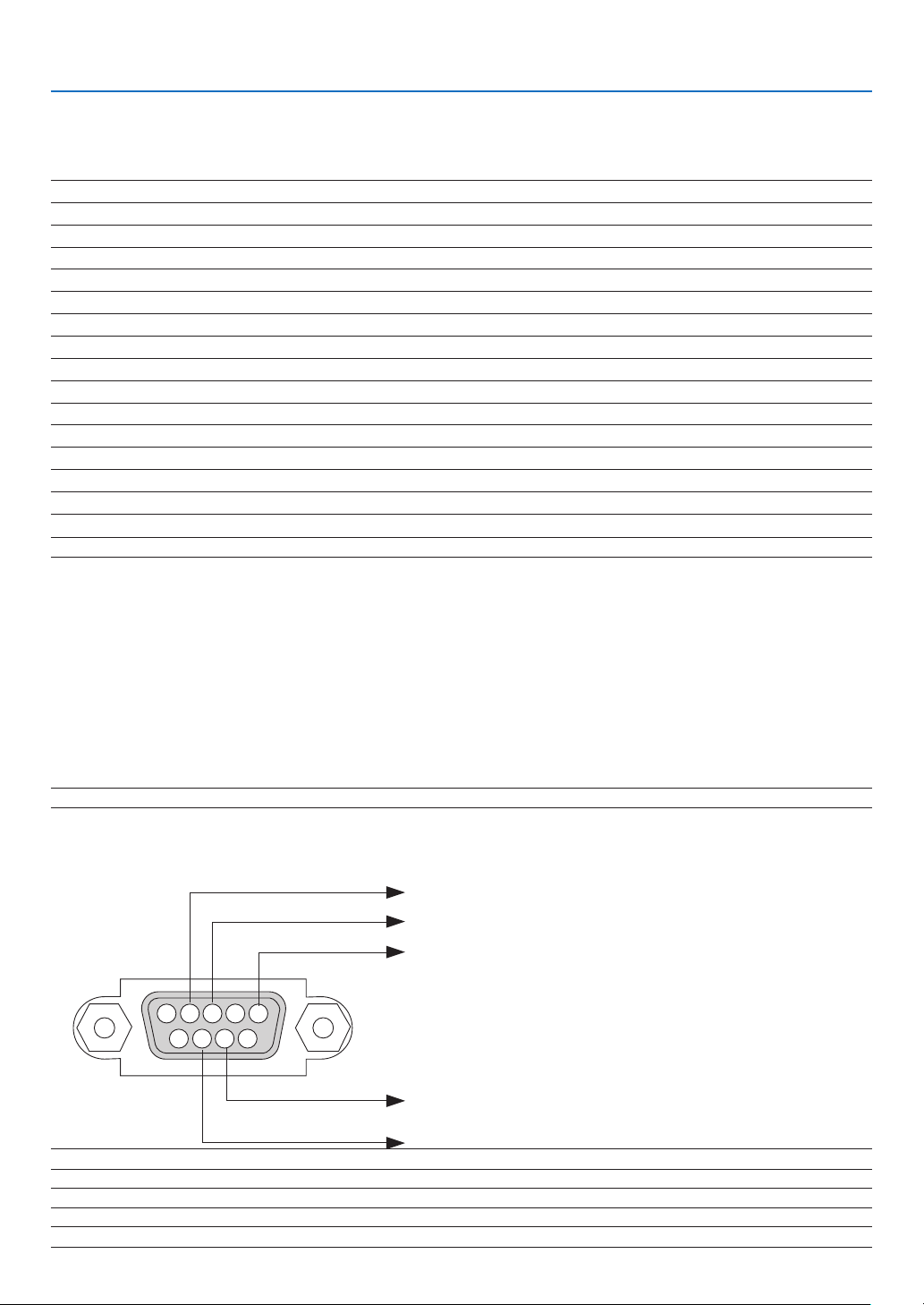
178
9. Appendix
❽ PC Control Codes and Cable Connection
PC Control Codes
Function Code Data
POWER ON 02H 00H 00H 00H 00H 02H
POWER OFF 02H 01H 00H 00H 00H 03H
INPUT SELECT HDMI1 02H 03H 00H 00H 02H 01H A1H A9H
INPUT SELECT HDMI2 02H 03H 00H 00H 02H 01H A2H AAH
INPUT SELECT DisplayPort 02H 03H 00H 00H 02H 01H A6H AEH
INPUT SELECT BNC 02H 03H 00H 00H 02H 01H 02H 0AH
INPUT SELECT BNC(CV) 02H 03H 00H 00H 02H 01H 06H 0EH
INPUT SELECT BNC(Y/C) 02H 03H 00H 00H 02H 01H 0BH 13H
INPUT SELECT COMPUTER 02H 03H 00H 00H 02H 01H 01H 09H
INPUT SELECT HDBaseT 02H 03H 00H 00H 02H 01H 20H 28H
PICTURE MUTE ON 02H 10H 00H 00H 00H 12H
PICTURE MUTE OFF 02H 11H 00H 00H 00H 13H
SOUND MUTE ON 02H 12H 00H 00H 00H 14H
SOUND MUTE OFF 02H 13H 00H 00H 00H 15H
NOTE:ContactyourlocaldealerforafulllistofthePCControlCodesifneeded.
Cable Connection
CommunicationProtocol
Baud rate �����������������������������������������38400 bps
Data length
��������������������������������������8 bits
Parity
�����������������������������������������������No parity
Stop bit
��������������������������������������������One bit
X on/off
��������������������������������������������None
Communications procedure
�������������Full duplex
NOTE:Dependingontheequipment,alowerbaudratemayberecommendedforlongcableruns.
PC Control Connector (D-SUB 9P)
NOTE 1: Pins 1, 4, 6 and 9 are no used.
NOTE2:Jumper“RequesttoSend”and“CleartoSend”togetheronbothendsofthecabletosimplifycableconnection.
NOTE3:Forlongcablerunsitisrecommendedtosetcommunicationspeedwithinprojectormenusto9600bps.
15243
67 98
ToGNDofPC
ToRxDofPC
ToTxDofPC
ToRTSofPC
ToCTSofPC

179
9. Appendix
❾ Troubleshooting Check List
Beforecontactingyourdealerorservicepersonnel,checkthefollowinglisttobesurerepairsareneededalsoby
referringtothe“Troubleshooting”sectioninyouruser’smanual.Thischecklistbelowwillhelpussolveyourproblem
moreefciently.
* Printthispageandthenextpageforyourcheck.
Frequency of occurrence □ always □sometimes(Howoften?_____________________) □other(__________________)
Power
□
No power (POWER indicator does not light blue)� See also “Status
Indicator (STATUS)”�
Power cord’s plug is fully inserted into the wall outlet�
□
Lamp cover is installed correctly�
□
Lamp Hours Used (lamp operation hours) was cleared after
□
lamp replacement�
No power even though you press and hold the POWER but-
□
ton�
□
Shut down during operation�
Power cord’s plug is fully inserted into the wall outlet�
□
Lamp cover is installed correctly�
□
[AUTO POWER OFF] is turned off (only models with the [AUTO
□
POWER OFF] function)�
[OFF TIMER] is turned off (only models with the [OFF TIMER]
□
function)�
Video and Audio
□
No image is displayed from your PC or video equipment to the
projector�
Still no image even though you connect the projector to the PC
□
first, then start the PC�
Enabling your notebook PC’s signal output to the projector�
□
• Acombinationoffunctionkeyswillenable/disabletheexter-
naldisplay.Usually,thecombinationofthe“Fn”keyalong
withoneofthe12functionkeysturnstheexternaldisplay
on or off.
No image (blue or black background, no display)�
□
Still no image even though you press the AUTO ADJUST
□
button�
Still no image even though you carry out [RESET] in the
□
projector’s menu�
Signal cable’s plug is fully inserted into the input connector
□
A message appears on the screen�
□
(_____________________________________________)
The source connected to the projector is active and available�
□
Still no image even though you adjust the brightness and/or
□
the contrast�
Input source’s resolution and frequency are supported by the
□
projector�
□
Image is too dark�
Remains unchanged even though you adjust the brightness
□
and/or the contrast�
□
Image is distorted�
Image appears to be trapezoidal (unchanged even though you
□
carry out the [KEYSTONE] adjustment)�
□
Parts of the image are lost�
Still unchanged even though you press the AUTO ADJUST
□
button�
Still unchanged even though you carry out [RESET] in the
□
projector’s menu�
□
Image is shifted in the vertical or horizontal direction�
Horizontal and vertical positions are correctly adjusted on a
□
computer signal�
Input source’s resolution and frequency are supported by the
□
projector�
Some pixels are lost�
□
□
Image is flickering�
Still unchanged even though you press the AUTO ADJUST
□
button�
Still unchanged even though you carry out [RESET] in the
□
projector’s menu�
Image shows flickering or color drift on a computer signal�
□
Still unchanged even though you change [FAN MODE] from
□
[HIGH ALTITUDE] to [AUTO]�
□
Image appears blurry or out of focus�
Still unchanged even though you checked the signal’s resolution
□
on PC and changed it to projector’s native resolution�
Still unchanged even though you adjusted the focus�
□
□
No sound�
Audio cable is correctly connected to the audio input of the
□
projector�
Still unchanged even though you adjusted the volume level�
□
AUDIO OUT is connected to your audio equipment (only models
□
with the AUDIO OUT connector)�
Other
□
Remote control does not work�
No obstacles between the sensor of the projector and the
□
remote control�
Projector is placed near a fluorescent light that can disturb the
□
infrared remote controls�
Batteries are new and are not reversed in installation�
□
□
Buttons on the projector cabinet do not work (only models with the
[CONTROL PANEL LOCK] function)
[CONTROL PANEL LOCK] is not turned on or is disabled in
□
the menu�
Still unchanged even though you press and hold the EXIT button
□
for a minimum of 10 seconds�
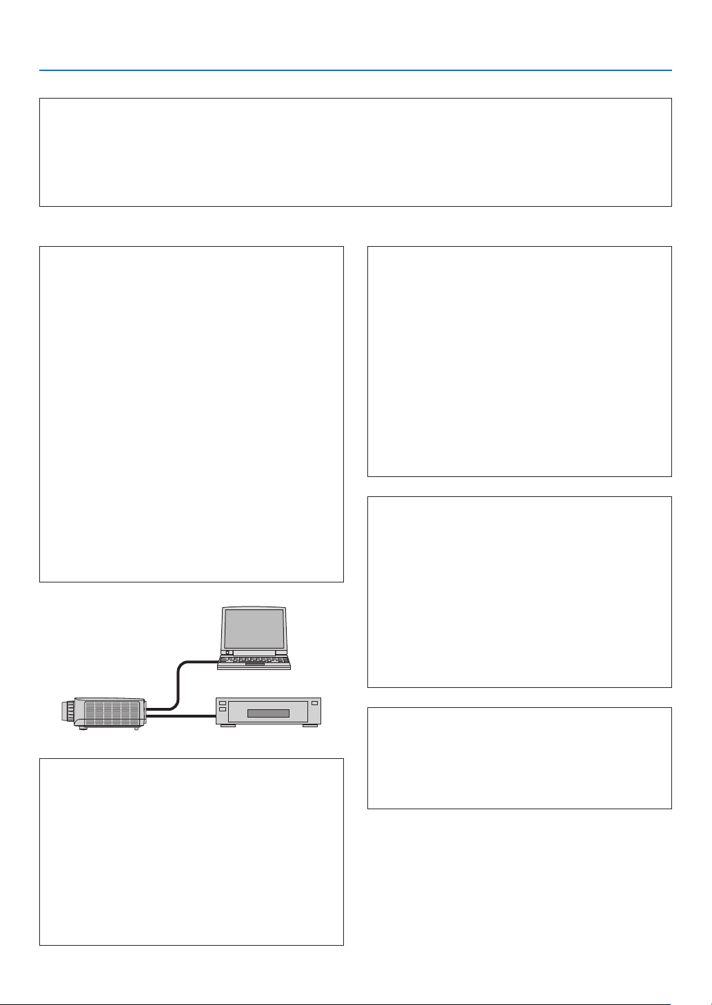
180
9. Appendix
In the space below please describe your problem in detail.
Information on application and environment where your projector is used
Projector
PC
Blu-rayplayer
Projector
Model number:
Serial No�:
Date of purchase:
Lamp operating time (hours):
Eco Mode: □ OFF □ ON
Information on input signal:
Horizontal synch frequency [ ] kHz
Vertical synch frequency [ ] Hz
Synch polarity H □ (+) □ (−)
V □ (+) □ (−)
Synch type □ Separate □ Composite
□ Sync on Green
STATUS Indicator:
Steady light □ Orange □ Green
Flashing light [ ] cycles
Remote control model number:
Installation environment
Screen size: inch
Screen type: □ White matte □ Beads □ Polarization
□ Wide angle □ High contrast
Throw distance: feet/inch/m
Orientation: □ Ceiling mount □ Desktop
Power outlet connection:
□
Connected directly to wall outlet
□ Connected to power cord extender or other (the
numberofconnectedequipment______________)
□ Connected to a power cord reel or other (the number
ofconnectedequipment______________)
Computer
Manufacturer:
Model number:
Notebook PC □ / Desktop □
Native resolution:
Refresh rate:
Video adapter:
Other:
Videoequipment
VCR, Blu-ray player, Video camera, Video game or other
Manufacturer:
Model number:
Signal cable
NECstandardorothermanufacturer’scable?
Model number: Length: inch/m
Distribution amplifier
Model number:
Switcher
Model number:
Adapter
Model number:

©NECDisplaySolutions,Ltd.2014 7N951971