
AR5000 ED CO_IB&IM_DB68-05069A_EN.indd 1 2015/3/20 16:14:44
Features of your new air conditioner
2-step cooling
2-step cooling function will quickly cool the room to reach the set temperature and then it
will adjust the fan speed and air flow direction automatically to help you stay comfortable and
refreshing.
Fast cooling
If you want the strong and cool air, just select Fast function! It will get you the strongest air!
Comfort cooling
If you want the comfortable and refreshing air, Comfort function will spread the cool air indirectly to
you, so that you can stay comfortable.
Single User
Use Single User function when you are alone at home. Single User function will minimize the
energy consumption with inverter technology and reduce your electricity bill by adjusting the
maximum operating capacity of the compressor.
Easy Filter
There is no grille to remove before separating the lter from the air conditioner! Therefore, lter can
be cleaned easily, more frequently! Frequent lter cleaning will prevent dust from entering into the
product or accumulating on the lter.
Smart Install
When the installation is done, your product will examine itself through trial operation to check if it
was installed properly.
Easy Installation
It’s so easy to install! You can easily hang the product on the wall and connect the pipes and wires
by opening the cover on the bottom of the product. Now you won’t have to tilt the product to
connect the pipe and the wires!
function
function will allow you to have deep, good night’s sleep by adjusting the
temperature, fan speed and air ow direction.
Correct Disposal of This Product
(Waste Electrical & Electronic Equipment)
(Applicable in countries with separate collection systems)
This marking on the product, accessories or literature indicates that the product and its electronic accessories (e.g. charger, headset, USB cable) should not be
disposed of with other household waste at the end of their working life. To prevent possible harm to the environment or human health from uncontrolled
waste disposal, please separate these items from other types of waste and recycle them responsibly to promote the sustainable reuse of material resources.
Household users should contact either the retailer where they purchased this product, or their local government office, for details of where and how
they can take these items for environmentally safe recycling.
Business users should contact their supplier and check the terms and conditions of the purchase contract. This product and its electronic accessories
should not be mixed with other commercial wastes for disposal.
English-2
AR5000 ED CO_IB&IM_DB68-05069A_EN.indd 2 2015/3/20 16:14:44
Contents
Preparation
Safety precautions . . . . . . . . . . . . . . . . . . . . . . . . . . . . . . . . . . . . . . . . . . . . . . . . . . . . . . . . . . . . . . . . . . . . . . . . . . . . . . . . . . . . . . . . . . . . . . . . . . . . . . . . . .4
Checking before use . . . . . . . . . . . . . . . . . . . . . . . . . . . . . . . . . . . . . . . . . . . . . . . . . . . . . . . . . . . . . . . . . . . . . . . . . . . . . . . . . . . . . . . . . . . . . . . . . . . . . . 10
Basic function
Checking the name of the parts . . . . . . . . . . . . . . . . . . . . . . . . . . . . . . . . . . . . . . . . . . . . . . . . . . . . . . . . . . . . . . . . . . . . . . . . . . . . . . . . . . . . . . . . . . . 11
Checking the remote controller . . . . . . . . . . . . . . . . . . . . . . . . . . . . . . . . . . . . . . . . . . . . . . . . . . . . . . . . . . . . . . . . . . . . . . . . . . . . . . . . . . . . . . . . . . . 12
Basic function. . . . . . . . . . . . . . . . . . . . . . . . . . . . . . . . . . . . . . . . . . . . . . . . . . . . . . . . . . . . . . . . . . . . . . . . . . . . . . . . . . . . . . . . . . . . . . . . . . . . . . . . . . . . . 14
Adjusting the air ow direction. . . . . . . . . . . . . . . . . . . . . . . . . . . . . . . . . . . . . . . . . . . . . . . . . . . . . . . . . . . . . . . . . . . . . . . . . . . . . . . . . . . . . . . . . . . . 16
Timer
Setting the On/O timer . . . . . . . . . . . . . . . . . . . . . . . . . . . . . . . . . . . . . . . . . . . . . . . . . . . . . . . . . . . . . . . . . . . . . . . . . . . . . . . . . . . . . . . . . . . . . . . . . . 17
mode. . . . . . . . . . . . . . . . . . . . . . . . . . . . . . . . . . . . . . . . . . . . . . . . . . . . . . . . . . . . . . . . . . . . . . . . . . . . . . . . . . . . . . . . . . . . . . . . . . . . . . . . . . . 19
Options
2-Step cooling function . . . . . . . . . . . . . . . . . . . . . . . . . . . . . . . . . . . . . . . . . . . . . . . . . . . . . . . . . . . . . . . . . . . . . . . . . . . . . . . . . . . . . . . . . . . . . . . . . . . 20
Using the Fast function. . . . . . . . . . . . . . . . . . . . . . . . . . . . . . . . . . . . . . . . . . . . . . . . . . . . . . . . . . . . . . . . . . . . . . . . . . . . . . . . . . . . . . . . . . . . . . . . . . . . 21
Using the Comfort function . . . . . . . . . . . . . . . . . . . . . . . . . . . . . . . . . . . . . . . . . . . . . . . . . . . . . . . . . . . . . . . . . . . . . . . . . . . . . . . . . . . . . . . . . . . . . . . 21
Using the Single user function. . . . . . . . . . . . . . . . . . . . . . . . . . . . . . . . . . . . . . . . . . . . . . . . . . . . . . . . . . . . . . . . . . . . . . . . . . . . . . . . . . . . . . . . . . . . . 22
Using the Quiet function . . . . . . . . . . . . . . . . . . . . . . . . . . . . . . . . . . . . . . . . . . . . . . . . . . . . . . . . . . . . . . . . . . . . . . . . . . . . . . . . . . . . . . . . . . . . . . . . . . 23
Using the Virus Doctor function . . . . . . . . . . . . . . . . . . . . . . . . . . . . . . . . . . . . . . . . . . . . . . . . . . . . . . . . . . . . . . . . . . . . . . . . . . . . . . . . . . . . . . . . . 24
Settings
Using the Auto clean function. . . . . . . . . . . . . . . . . . . . . . . . . . . . . . . . . . . . . . . . . . . . . . . . . . . . . . . . . . . . . . . . . . . . . . . . . . . . . . . . . . . . . . . . . . . . . 25
Setting the Beep sound . . . . . . . . . . . . . . . . . . . . . . . . . . . . . . . . . . . . . . . . . . . . . . . . . . . . . . . . . . . . . . . . . . . . . . . . . . . . . . . . . . . . . . . . . . . . . . . . . . . 25
Others
Cleaning the air conditioner. . . . . . . . . . . . . . . . . . . . . . . . . . . . . . . . . . . . . . . . . . . . . . . . . . . . . . . . . . . . . . . . . . . . . . . . . . . . . . . . . . . . . . . . . . . . . . . 26
Maintaining the air conditioner. . . . . . . . . . . . . . . . . . . . . . . . . . . . . . . . . . . . . . . . . . . . . . . . . . . . . . . . . . . . . . . . . . . . . . . . . . . . . . . . . . . . . . . . . . . . 29
Troubleshooting . . . . . . . . . . . . . . . . . . . . . . . . . . . . . . . . . . . . . . . . . . . . . . . . . . . . . . . . . . . . . . . . . . . . . . . . . . . . . . . . . . . . . . . . . . . . . . . . . . . . . . . . . . 30
Installation
Safety precautions . . . . . . . . . . . . . . . . . . . . . . . . . . . . . . . . . . . . . . . . . . . . . . . . . . . . . . . . . . . . . . . . . . . . . . . . . . . . . . . . . . . . . . . . . . . . . . . . . . . . . . . . 32
Choosing the installation location . . . . . . . . . . . . . . . . . . . . . . . . . . . . . . . . . . . . . . . . . . . . . . . . . . . . . . . . . . . . . . . . . . . . . . . . . . . . . . . . . . . . . . . . . 33
Accessories . . . . . . . . . . . . . . . . . . . . . . . . . . . . . . . . . . . . . . . . . . . . . . . . . . . . . . . . . . . . . . . . . . . . . . . . . . . . . . . . . . . . . . . . . . . . . . . . . . . . . . . . . . . . . . . 36
Fixing the installation plate. . . . . . . . . . . . . . . . . . . . . . . . . . . . . . . . . . . . . . . . . . . . . . . . . . . . . . . . . . . . . . . . . . . . . . . . . . . . . . . . . . . . . . . . . . . . . . . . 38
Disassembling/Assembling the Cover panel for indoor unit installation . . . . . . . . . . . . . . . . . . . . . . . . . . . . . . . . . . . . . . . . . . . . . . . . . . . . 39
Connecting the assembly cable . . . . . . . . . . . . . . . . . . . . . . . . . . . . . . . . . . . . . . . . . . . . . . . . . . . . . . . . . . . . . . . . . . . . . . . . . . . . . . . . . . . . . . . . . . . 41
Installing and connecting the assembly pipe of the indoor unit . . . . . . . . . . . . . . . . . . . . . . . . . . . . . . . . . . . . . . . . . . . . . . . . . . . . . . . . . . . . 43
Evacuating the indoor unit . . . . . . . . . . . . . . . . . . . . . . . . . . . . . . . . . . . . . . . . . . . . . . . . . . . . . . . . . . . . . . . . . . . . . . . . . . . . . . . . . . . . . . . . . . . . . . . . 44
Cutting or extending the pipe . . . . . . . . . . . . . . . . . . . . . . . . . . . . . . . . . . . . . . . . . . . . . . . . . . . . . . . . . . . . . . . . . . . . . . . . . . . . . . . . . . . . . . . . . . . . . 44
Installing and connecting the drain hose of the indoor unit . . . . . . . . . . . . . . . . . . . . . . . . . . . . . . . . . . . . . . . . . . . . . . . . . . . . . . . . . . . . . . . . 46
Changing direction of the drain hose. . . . . . . . . . . . . . . . . . . . . . . . . . . . . . . . . . . . . . . . . . . . . . . . . . . . . . . . . . . . . . . . . . . . . . . . . . . . . . . . . . . . . . 47
Evacuating the connected pipes. . . . . . . . . . . . . . . . . . . . . . . . . . . . . . . . . . . . . . . . . . . . . . . . . . . . . . . . . . . . . . . . . . . . . . . . . . . . . . . . . . . . . . . . . . . 48
Performing the gas leak tests. . . . . . . . . . . . . . . . . . . . . . . . . . . . . . . . . . . . . . . . . . . . . . . . . . . . . . . . . . . . . . . . . . . . . . . . . . . . . . . . . . . . . . . . . . . . . . 50
Fixing the indoor unit in place . . . . . . . . . . . . . . . . . . . . . . . . . . . . . . . . . . . . . . . . . . . . . . . . . . . . . . . . . . . . . . . . . . . . . . . . . . . . . . . . . . . . . . . . . . . . . 51
Fixing the outdoor unit in place . . . . . . . . . . . . . . . . . . . . . . . . . . . . . . . . . . . . . . . . . . . . . . . . . . . . . . . . . . . . . . . . . . . . . . . . . . . . . . . . . . . . . . . . . . . 51
Smart Install mode. . . . . . . . . . . . . . . . . . . . . . . . . . . . . . . . . . . . . . . . . . . . . . . . . . . . . . . . . . . . . . . . . . . . . . . . . . . . . . . . . . . . . . . . . . . . . . . . . . . . . . . . 52
Final check and trial operation. . . . . . . . . . . . . . . . . . . . . . . . . . . . . . . . . . . . . . . . . . . . . . . . . . . . . . . . . . . . . . . . . . . . . . . . . . . . . . . . . . . . . . . . . . . . . 54
Pump down procedure (when removing the product) . . . . . . . . . . . . . . . . . . . . . . . . . . . . . . . . . . . . . . . . . . . . . . . . . . . . . . . . . . . . . . . . . . . . . 54
How to connect your extended power cables. . . . . . . . . . . . . . . . . . . . . . . . . . . . . . . . . . . . . . . . . . . . . . . . . . . . . . . . . . . . . . . . . . . . . . . . . . . . . . 55
English-3
AR5000 ED CO_IB&IM_DB68-05069A_EN.indd 3 2015/3/20 16:14:44
Safety precautions
Before using your new air conditioner, please read this manual thoroughly to ensure
that you know how to safely and eciently operate the extensive features and
functions of your new appliance.
Because the following operating instructions cover various models, the
characteristics of your air conditioner may dier slightly from those described in this
manual. If you have any questions, call your nearest contact center or nd help and
information online at www.samsung.com.
Important safety symbols and precautions:
WARNING
Hazards or unsafe practices that may result in severe
personal injury or death.
CAUTION
Hazards or unsafe practices that may result in minor
personal injury or property damage.
Follow directions. Cut-o the power supply.
Do NOT attempt. Do NOT disassemble.
Make sure the machine is grounded to prevent electric shock.
FOR INSTALLATION
WARNING
Use the power line with the power specications of the product or higher
and use the power line for this appliance only. In addition, do not use an
extension line.
Extending the power line may result in electric shock or fire.
Do not use an electric transformer. It may result in electric shock or fire.
If the voltage/frequency/rated current condition is different, it may cause fire.
The installation of this appliance must be performed by a qualied
technician or service company.
Failing to do so may result in electric shock, fire, explosion, problems with the
product, or injury and may also void warranty on the installed product.
Install a Isolation Switch next to the Air Conditioner (but not on the panels
of the Air Conditioner)and circuit breaker dedicated to the air conditioner.
Failing to do so may result in electric shock or fire.
Fix the outdoor unit rmly so that the electric part of the outdoor unit is not
exposed.
Failing to do so may result in electric shock, fire, explosion, problems with the
product.
English-4
AR5000 ED CO_IB&IM_DB68-05069A_EN.indd 4 2015/3/20 16:14:44
Do not install this appliance near a heater, inammable material. Do
not install this appliance in a humid, oily or dusty location, in a location
exposed to direct sunlight and water (rain drops). Do not install this
appliance in a location where gas may leak.
This may result in electric shock or fire.
Never install the outdoor unit in a location such as on a high external wall
where it could fall.
If the outdoor unit falls, it may result in injury, death or property damage.
This appliance must be properly grounded. Do not ground the appliance to a
gas pipe, plastic water pipe, or telephone line.
Failure to do so may result in electric shock, fire, and explosion.
Make sure to use a socket-outlet with ground.
FOR INSTALLATION
CAUTION
Install your appliance on a level and hard oor that can support its weight.
Failing to do so may result in abnormal vibrations, noise, or problems with the
product.
Install the draining hose properly so that water is drained correctly.
Failing to do so may result in water overflowing and property damage. Avoid
adding drain to waste pipes as odours may arise in the future.
When installing the outdoor unit, make sure to connect the draining hose
so that draining is performed correctly.
The water generated during the heating operation by the outdoor unit may
overflow and result in property damage.
In particular, in winter, if a block of ice falls, it may result in injury, death or
property damage.
FOR POWER SUPPLY
WARNING
When the circuit breaker is damaged, contact your nearest service center.
Do not pull or excessively bend the power line. Do not twist or tie the
power line. Do not hook the power line over a metal object, place a heavy
object on the power line, insert the power line between objects, or push
the power line into the space behind the appliance.
This may result in electric shock or fire.
English-5
PrEParaTIOn01
AR5000 ED CO_IB&IM_DB68-05069A_EN.indd 5 2015/3/20 16:14:44
Safety precautions
FOR POWER SUPPLY
CAUTION
When not using the air conditioner for a long period of time or during a
thunder/lightning storm, cut the power at the circuit breaker.
Failing to do so may result in electric shock or fire.
FOR USING
WARNING
If the appliance is ooded, please contact your nearest service center.
Failing to do so may result in electric shock or fire.
If the appliance generates a strange noise, a burning smell or smoke, cut-
o the power supply immediately and contact the nearest service center.
Failing to do so may result in electric shock or fire.
In the event of a gas leak (such as propane gas, LP gas, etc.), ventilate
immediately without touching the power line. Do not touch the appliance
or power line.
Do not use a ventilating fan.
A spark may result in an explosion or fire.
To reinstall the air conditioner, please contact your nearest service center.
Failing to do so may result in problems with the product, water leakage,
electric shock, or fire.
A delivery service for the product is not provided. If you reinstall the product in
another location, additional construction expenses and an installation fee will
be charged.
Especially, when you wish to install the product in an unusual location such as
in an industrial area or near the seaside where it is exposed to the salt in the air,
please contact your nearest service center.
Do not touch the circuit breaker with wet hands.
This may result in electric shock.
Do not turn the air conditioner o with the circuit breaker while it is
operating.
Turning the air conditioner off and then on again with the circuit breaker may
cause a spark and result in electric shock or fire.
After unpacking the air conditioner, keep all packaging materials well
out of the reach of children, as packaging materials can be dangerous to
children.
If a child places a bag over its head, it may result in suffocation.
English-6
AR5000 ED CO_IB&IM_DB68-05069A_EN.indd 6 2015/3/20 16:14:44
Do not touch the air ow blade with your hands or ngers during the
heating operation.
This may result in electric shock or burns.
Do not insert your ngers or foreign substances into the air inlet/outlet of
the air conditioner.
Take special care that children do not injure themselves by inserting their
fingers into the product.
Do not strike or pull the air conditioner with excessive force.
This may result in fire, injury, or problems with the product.
Do not place an object near the outdoor unit that allows children to climb
onto the machine.
This may result in children seriously injuring themselves.
Do not use this air conditioner for long periods of time in badly ventilated
locations or near inrm people.
Since this may be dangerous due to a lack of oxygen, Open a window at least
once an hour.
If any foreign substance such as water has entered the appliance, cut-o
the power supply and contact the nearest service center.
Failing to do so may result in electric shock or fire.
Do not attempt to repair, disassemble, or modify the appliance yourself.
Do not use any fuse (such as cooper, steel wire, etc.)other than the standard
fuse.
Failing to do so may result in electric shock, fire, problems with the product, or
injury.
English-7
PrEParaTIOn01
AR5000 ED CO_IB&IM_DB68-05069A_EN.indd 7 2015/3/20 16:14:44
Safety precautions
FOR USING
CAUTION
Do not place objects or devices under the indoor unit.
Water dripping from the indoor unit may result in fire or property damage.
(example electrical appliances)
Check that the installation frame of the outdoor unit is not broken at least
once a year.
Failing to do so may result in injury, death or property damage.
Max current is measured according to IEC standard for safety and current is
measured according to ISO standard for energy eciency.
Do not stand on top of the appliance or place objects (such as laundry,
lighted candles, lighted cigarettes, dishes, chemicals, metal objects, etc.) on
the appliance.
This may result in electric shock, fire, problems with the product, or injury.
Do not operate the appliance with wet hands.
This may result in electric shock.
Do not spray volatile material such as insecticide onto the surface of the
appliance.
As well as being harmful to humans, it may also result in electric shock, fire or
problems with the product.
Do not drink the water from the air conditioner.
The water may be harmful to humans.
Do not apply a strong impact to the remote controller and do not
disassemble the remote controller.
Do not touch the pipes connected with the product.
This may result in burns or injury.
Do not use this air conditioner to preserve precision equipment, food,
animals, plants or cosmetics, or for any other unusual purposes.
This may result in property damage.
Avoid directly exposing humans, animals or plants from the air ow from
the air conditioner for long periods of time.
This may result in harm to humans, animals or plants.
English-8
AR5000 ED CO_IB&IM_DB68-05069A_EN.indd 8 2015/3/20 16:14:44
This appliance is not intended for use by persons (including children) with
reduced physical, sensory or mental capabilities, or lack of experience
and knowledge, unless they have been given supervision or instruction
concerning use of the appliance by a person responsible for their safety.
Children should be supervised to ensure that they do not play with the
appliance.
FOR CLEANING
WARNING
Do not clean the appliance by spraying water directly onto it. Do not use
benzene, thinner or alcohol to clean the appliance.
This may result in discoloration, deformation, damage, electric shock or fire.
Before cleaning or performing maintenance, cut-o the power supply and
wait until the fan stops.
Failing to do so may result in electric shock or fire.
FOR CLEANING
CAUTION
Take care when cleaning the surface of the heat exchanger of the outdoor
unit since it has sharp edges.
This should be done by a qualified technician please contact your installer or
service center.
Do not clean the inside of the air conditioner by yourself.
For cleaning inside the appliance, contact your nearest service center.
When cleaning the internal filter, refer to the descriptions in the ‘Cleaning the
air conditioner’ section.
Failure to do may result in damage, electric shock or fire.
We suggest that the temperature should be set between 21°C - 23°C to reduce
energy consumption.
The air conditioner should be turned o in an unoccupied areas.
The heat may be caused by the excessive lighting or equipment that is turned
on unnecessarily. You should reduce heat in the air-conditioned area.
English-9
PrEParaTIOn01
AR5000 ED CO_IB&IM_DB68-05069A_EN.indd 9 2015/3/20 16:14:44
Checking before use
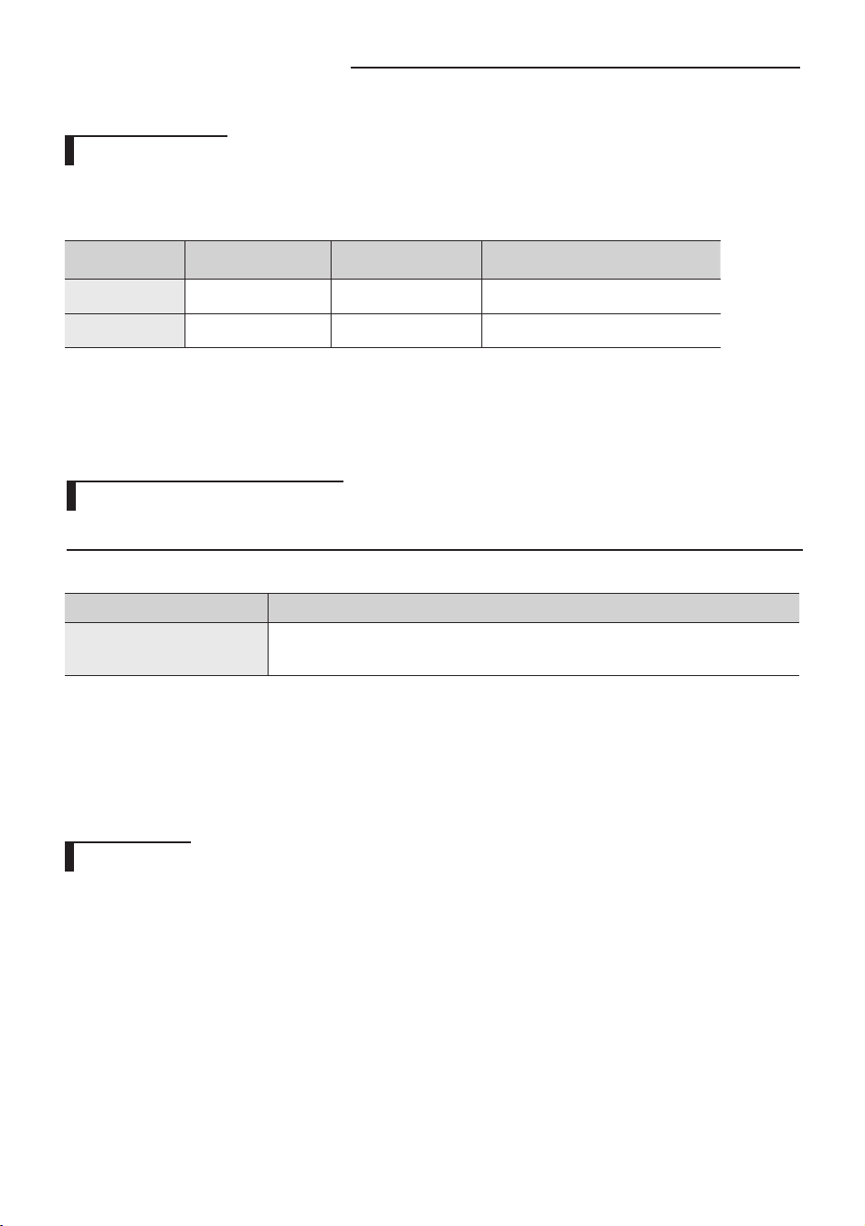
Operation ranges
The table below indicates the temperature and humidity ranges the air
conditioner can be operated within. Refer to the table for ecient use.
f If the air conditioner operates in cooling mode for long period of time in high humidity area, dew may be formed.
Maintaining your air conditioner
Internal protections via the unit control system
f This internal protection operates if an internal fault occurs in the air conditioner.
Type Description
Protect compressor
The air conditioner does not start operating immediately to help protect the compressor
of the outdoor unit after it has been started.
Smart install
f Through Smart install function, installer can check if the installation was done properly.
f If the installation was not done properly, error indicator will turn on the indoor unit display.
Therefore user will know if the installation was done properly or not.
Mode
Indoor
temperature
Outdoor
temperature
Indoor humidity
Cooling
16 ˚C~
32 ˚C 16 ˚C~46 ˚C Relative humidity 80% or less
Dry
18 ˚C~32 ˚C 16 ˚C~46 ˚C -
English-10
AR5000 ED CO_IB&IM_DB68-05069A_EN.indd 10 2015/3/20 16:14:45
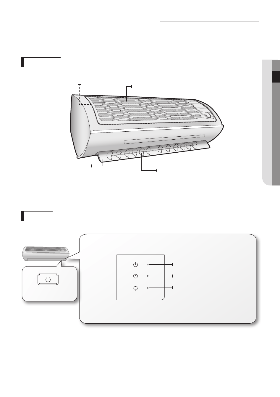
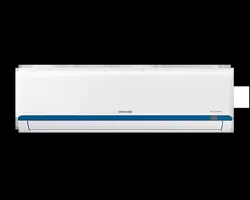
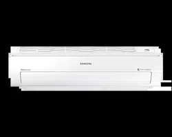
Main parts
Your air conditioner may slightly look dierent from illustration shown below depending on your model.
Checking the name of the parts
Display
Air lter
Air ow blade
(up and down)
Air ow blade
(left and right)
Air intake
Power button/
Remote controller receiver
Virus Doctor indicator
Timer/Auto clean indicator
Power indicator
English-11
BaSIC FunCTIOn02
AR5000 ED CO_IB&IM_DB68-05069A_EN.indd 11 2015/3/20 16:14:45
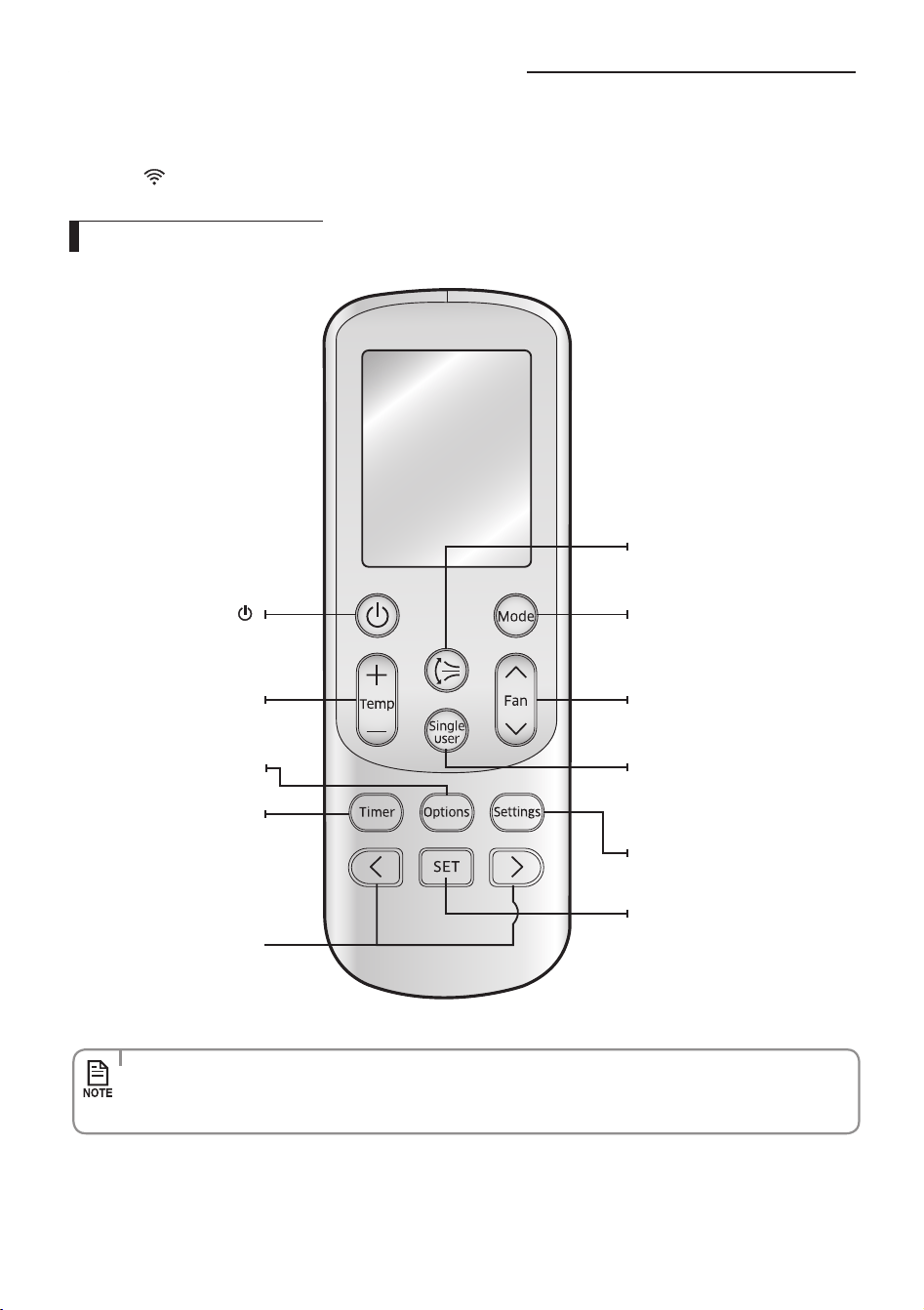
Checking the remote controller
Remote controller buttons
•Pointtheremotecontrollertowardstheremotecontrollerreceiveroftheindoorunit.
•Whenyouproperlypressthebuttonontheremotecontroller,youwillhearbeepsoundfromtheindoorunitandatransmit
indicator(
) appears on the remote controller display.
•Incaseyouwishtocanceltheoptionsorsettingsthatyouhavejustset,presstheOptions or Settings button again,
then the most recently selected item will blink and you may simply cancel it by pressing the SET button while
selected item is blinking.
Power
Turn on/o the air
conditioner
Temp + –
Increase/Decrease the
temperature by 1 ˚C.
Options
Select options during operation
Timer
Select Timer option
Directional < >
Move through the Timer,
Options or Settings menu to
make a selection
Vertical air swing
Activate/Deactivate vertical air ow
blade movement automatically
Single User
Turn on/o the Single User function
which reduces energy usage while
operating in cool
mode.
Settings
Select settings
SET
Set/Cancel the selected option or
setting
Mode
Set one of the 4 operating modes
Fan
Adjust the fan speed
English-12
AR5000 ED CO_IB&IM_DB68-05069A_EN.indd 12 2015/3/20 16:14:45
•Makesurethatthewaterdoesnotgettotheremotecontroller.
•Heat mode and the following function are displayed on the remote controller display but not
supported in this model.
- d'light Cool / Usage / Filter Reset / Display
•Whenturningoandturningontheremotecontroller,theTimer, Options and Settings set before
turning o the remote controller are cancelled. However, the fan direction does not change.
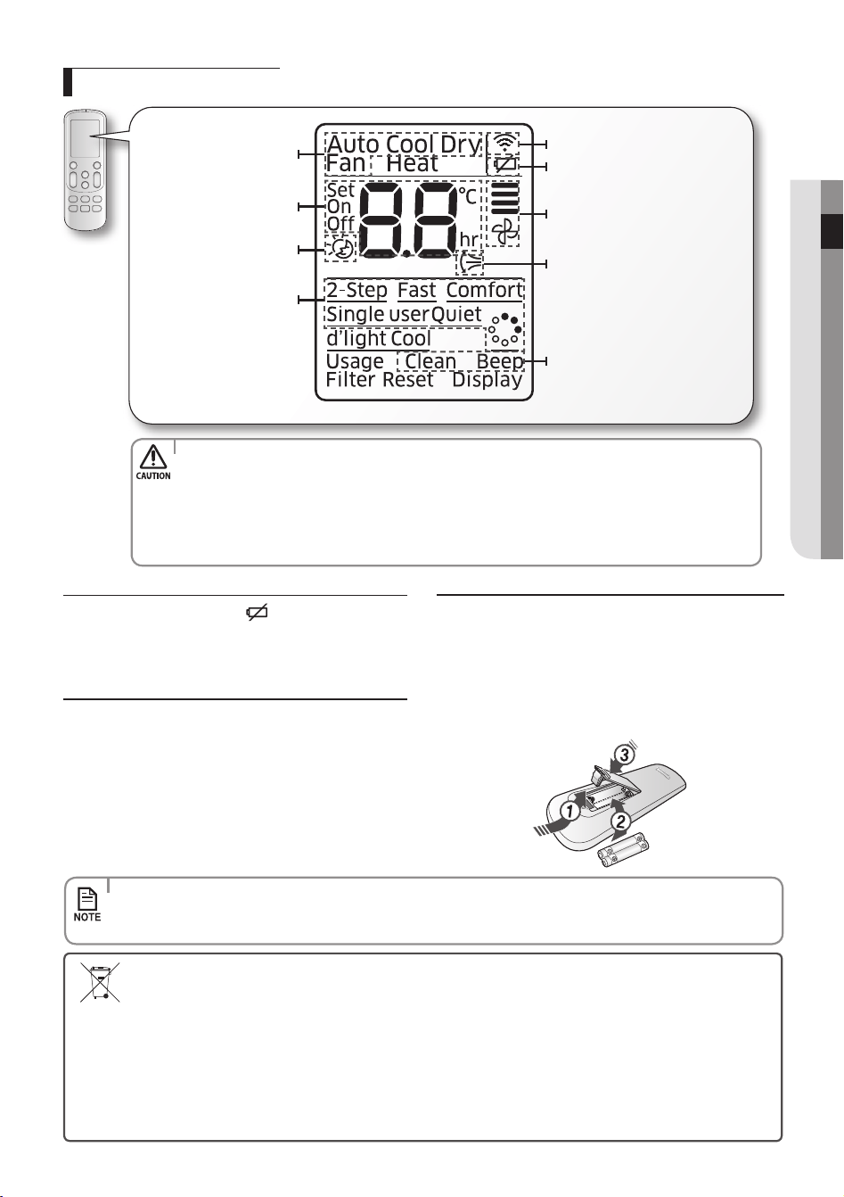
Remote controller display
Low Battery warning
When the battery is exhausted, (
) will be displayed in the
remote controller display. When the icon appears, change
the batteries. The remote controller requires two 1.5 V AAA
type batteries.
Storing the remote controller
When you do not use the remote controller for long time,
remove the batteries from the remote controller and store it.
Inserting the batteries
1. Push the lever as arrow indicates on the rear side of the
remote controller and pull up.
2. Insert two AAA batteries.
Check and match the “+” and “-” signs accordingly. Make sure
you have inserted the batteries in correct position.
3. Close the cover by place it back to its original position.
You should hear click sound when the cover is locked properly.
•Thesignalmaynotbereceivedproperlyifelectronicourescentlampssuchasinverterourescentlampsare
operating in the same space.
•Ifotherelectricalproductsoperatebytheremotecontroller,callyournearestcontactcenter.
Operation mode
indicator
Set temperature/ Time (for
Timer option) indicator
good'sleep indicator
Options indicator
Transmit indicator
Low battery indicator
Fan speed indicator
Vertical air swing indicator
Settings indicator
Correct disposal of batteries in this product
(Applicable in countries with separate collection systems)
This marking on the battery, manual or packaging indicates that the batteries in this product should not be disposed of with
other household waste at the end of their working life. Where marked, the chemical symbols Hg, Cd or Pb indicate that the
battery contains mercury, cadmium or lead above the reference levels in EC Directive 2006/66.
If batteries are not properly disposed of, these substances can cause harm to human health or the environment.
To protect natural resources and to promote material reuse, please separate batteries from other types of waste and recycle
them through your local, free battery return system.
English-13
BaSIC FunCTIOn02
AR5000 ED CO_IB&IM_DB68-05069A_EN.indd 13 2015/3/20 16:14:45
Basic function
Basic operation is an operation mode that can be selected by pressing the Mode button.
auto(2-Step Cooling)
In Auto mode, the air conditioner will automatically set the temperature and fan speed depending on the room
temperature.
•2-Step Cooling mode sets the air conditioner to operate in Fast + Cool mode when set temperature is lower than indoor
temperature, and then the air conditioner will automatically operate in Dry mode when indoor temperature reaches set
temperature.
Cool
In Cool mode, the air conditioner will cool your room. You can adjust the temperature and the fan speed to feel cooler in hot
season.
•If current outside temperature is much higher than the selected indoor temperature, it may take time to bring the inner
temperature to the desired coolness.
•Quiet mode makes the noise quieter during the operation of the indoor unit in the Cool mode.
Dry
The air conditioner in Dry mode acts like a dehumidier by removing moisture from the indoor air.
Dry mode makes the air feel refreshing in a humid climate.
To activate the Dry mode, set temperature on the remote controller should be lower than indoor room temperature.
Fan
Fan mode can be selected to circulate your room. Fan mode will be helpful to refresh the stale air in your room.
English-14
AR5000 ED CO_IB&IM_DB68-05069A_EN.indd 14 2015/3/20 16:14:46
Basic function
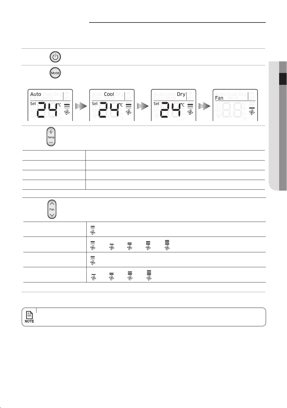
Press the button to turn on the air conditioner.
Press the
button to set the operating mode.
•EachtimeyoupresstheMode button, the mode will change in order of Auto, Cool, Dry and Fan.
Press the button to adjust the temperature.
Auto You can adjust the set temperature by 1 °C within the range of 16 °C~30 °C.
Cool You can adjust the set temperature by 1 °C within the range of 16 °C~30 °C.
Dry You can adjust the set temperature by 1 °C within the range of 18 °C~30 °C.
Fan Temperature adjustment is not possible.
Press the button to set the desired fan speed.
Auto
(Auto)
Cool
(Auto), (Low), (Med), (High), (Turbo)
Dry
(Auto)
Fan
(Low), (Med), (High), (Turbo)
•Drymodeisonlyavailableinthecoolingmode.
English-15
BaSIC FunCTIOn02
AR5000 ED CO_IB&IM_DB68-05069A_EN.indd 15 2015/3/20 16:14:46
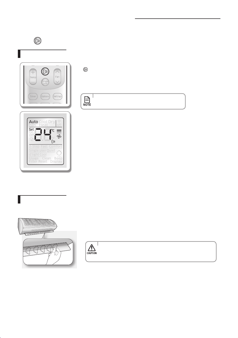
adjusting the air ow direction
Horizontal air ow
Move the blade pin lever left or right to keep the air ow direction in a constant
position you prefer.
•Toavoidtheriskofpersonalinjuries,adjustingthehorizontalairow
direction should only be done when the unit is turned o completely.
There is a potential risk of personal injury when the unit is mishandled.
This function will allow you to adjust the air ow direction vertically.
Press the
button to make air ow blades vertically.
Remote controller display
f To keep the air ow direction in a constant direction, press the
button again.
The air ow blade(s) will stop the movement.
If you adjust the vertical air ow blade manually, it may not close
completely when you turn o the air conditioner.
•Adjustingtheairowdirectionisnotavailablein
good'sleep mode while it is in cool mode.
Vertical air ow
English-16
AR5000 ED CO_IB&IM_DB68-05069A_EN.indd 16 2015/3/20 16:14:47
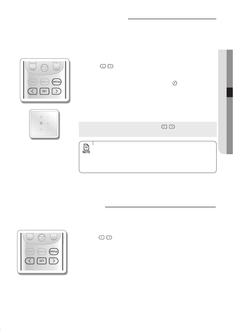
Setting the On/O timer
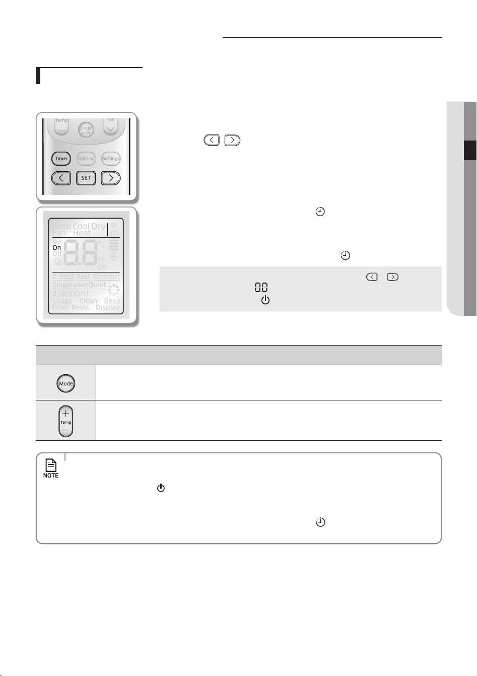
Setting the On timer
When the air conditioner is o;
Remote controller display
1. Press the Timer button to select (On).
- (On) indicator will keep blinking and you can set the time.
2. Press the
button to set the time.
- You can set the time in half hour unit from 30 minutes (0.5 on the display) ~
3hours and hour unit from 3~24 hours.
- Time can be set from minimum 30 minutes to maximum 24 hours.
3. Press the SET button to complete the On timer setting.
- (On) indicator and the set time of the timer will be displayed on the remote
controller display and the Timer indicator (
)
will be displayed on the indoor
unit display.
- On timer setting will be cancelled if you don't press the SET button within
10seconds after setting the time. Therefore, check for the (On) indicator on the
remote controller display and the Timer indicator (
)
on the indoor unit display.
Cancel
f Press the Timer button select (On) press the
or button
set the timer to press the SET button.
f Press the Power (
) button.
additional options available in On time
You can select from Auto/Cool/Dry/Fan.
You can set the temperature after selecting the operation mode.
Temperature adjustment is available when Auto/Cool/Dry mode is selected.
•When On timer setting is completed, the set status will be displayed for 3 seconds, and then only (On)
indicator will remain on the remote controller display thereafter.
•If you press the Power
button on the indoor unit after setting the On timer from the remote controller,
Timer indicator on the indoor unit display will disappear and the On timer will be cancelled. Even though the
On timer is cancelled, (On) indicator on the remote controller will remain displayed.
•When the On timer is set while the air conditioner is o, Timer indicator (
) will be displayed and remain on
until the On timer turns on.
English-17
TImEr03
AR5000 ED CO_IB&IM_DB68-05069A_EN.indd 17 2015/3/20 16:14:48
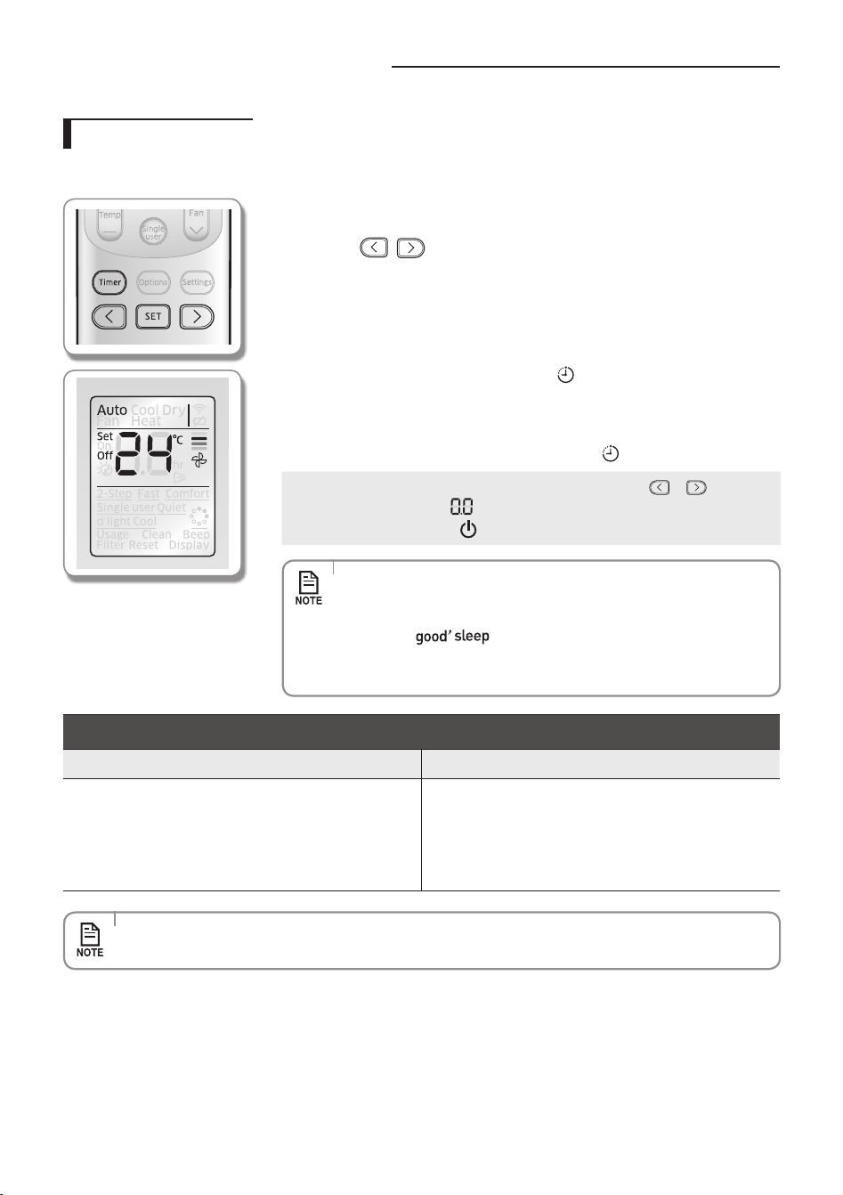
Setting the O timer
When the air conditioner is on;
Remote controller display
1. Press the Timer to select (O).
- (O) indicator will keep blinking and you can set the time.
2. Press the
button to set the time.
- You can set the time in half hour unit from 30 minutes (0.5 on the display) ~
3hours and hour unit from 3~24 hours.
- Time can be set from minimum 30 minutes to maximum 24 hours.
3. Press the SET button to complete the O timer setting.
- (O) indicator and the set time of the timer will be displayed on the remote
controller display and the Timer indicator (
)
will be displayed on the indoor
unit display.
- O timer setting will be cancelled if you don't press the SET button within
10seconds after setting the time. Therefore, check for the (O) indicator on the
remote controller display and the Timer indicator (
)
on the indoor unit display.
Cancel
f Press the Timer button select (O) press the
or button
set the timer to press the SET button.
f Press the Power (
) button.
•O timer may not work depending on the On/O status of the indoor unit
and the On/O status of the indicator on the remote controller display.
•OnlythelatestsettingtimerwillbeappliedbetweentheOnTimer/O
Timer and
O timer functions.
•Aftersettingthetimer,thesettimewillbedisplayedfor3secondsbefore
it disappears.
Combining On Timer and O Timer
When the air conditioner is o When the air conditioner is on
When set time on On timer is shorter than O timer
Ex) On timer : 3 hours, O timer : 5 hours
- The air conditioner will turn on after 3 hours from the
moment you have set the timer and the air conditioner will
remain on for 2 hours and then turn o automatically.
When set time on On timer is longer than O timer
Ex) On timer : 3 hours, O timer : 1 hour
- The air conditioner will turn o after 1 hour from the
moment you have set the timer and turn on after 2 hours
from the moment it was turned o.
•Set time for the On timer and the O timer should be dierent from each other.
Setting the On/O timer
English-18
AR5000 ED CO_IB&IM_DB68-05069A_EN.indd 18 2015/3/20 16:14:48
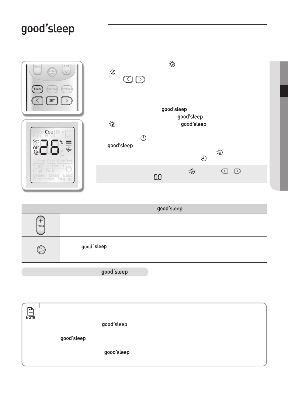
mode
For a comfortable sleep, the air conditioner will operate in 3 stages in order of Fall asleep Sound sleep Wake up stage.
When the air conditioner is operating in Cool mode;
Remote controller display
1. Press the Timer button to select ( ).
- (
) indicator will keep blinking and you can set the time.
2. Press the
button to set the time.
- You can set the time in half hour unit from 30 minutes (0.5 on the display) ~
3hours and hour unit from 3~12 hours.
- Time can be set from minimum 30 minutes to maximum 12 hours.
- Default time setting for the
mode is 8 hours.
3. Press the SET button to complete the
mode setting.
- (
) indicator and the set time of the mode will be displayed on
the remote controller display.
- Timer indicator (
)
will be displayed on the indoor unit display.
- mode setting will be cancelled if you don't press the SET button within
10 seconds after setting the time. Therefore, check for the ( ) indicator on the
remote controller display and the Timer indicator ( ) on the indoor unit display.
Cancel
f Press the Timer button select (
) press the or button
set the timer to press the SET button.
Additional options available in mode
You can adjust the set temperature by 1 °C within the range of 16 °C~30 °C.
When the mode is on.
In Cool mode : Air ow direction will be adjusted automatically.
Temperature and fan speed change in mode
•Fall asleep: Eases you into sleep by dropping the temperature.
•Sound sleep: Relaxes your body and raises your temperature slightly.
•Wake up: Allows you to wake up from comfortable intermittent air and it makes you feel refreshed.
•Recommended set temperature is between 25
°C ~ 27 °C for cooling.
•If the set temperature is too low, you may feel cold during sleep or catch a cold.
•Optimal operation hour of
mode is 8 hours. Therefore, if the time is set too short or long, you
may not feel as comfortable as you would expect.
•If the
mode is set over 5 hours, Wake up stage will begin when 1 hour is remaining in the
operation time and the air conditioner will stop automatically.
•When the On timer and the
function is set simultaneously, the air conditioner will only apply
the function that was set later.
English-19
TImEr03
AR5000 ED CO_IB&IM_DB68-05069A_EN.indd 19 2015/3/20 16:14:49
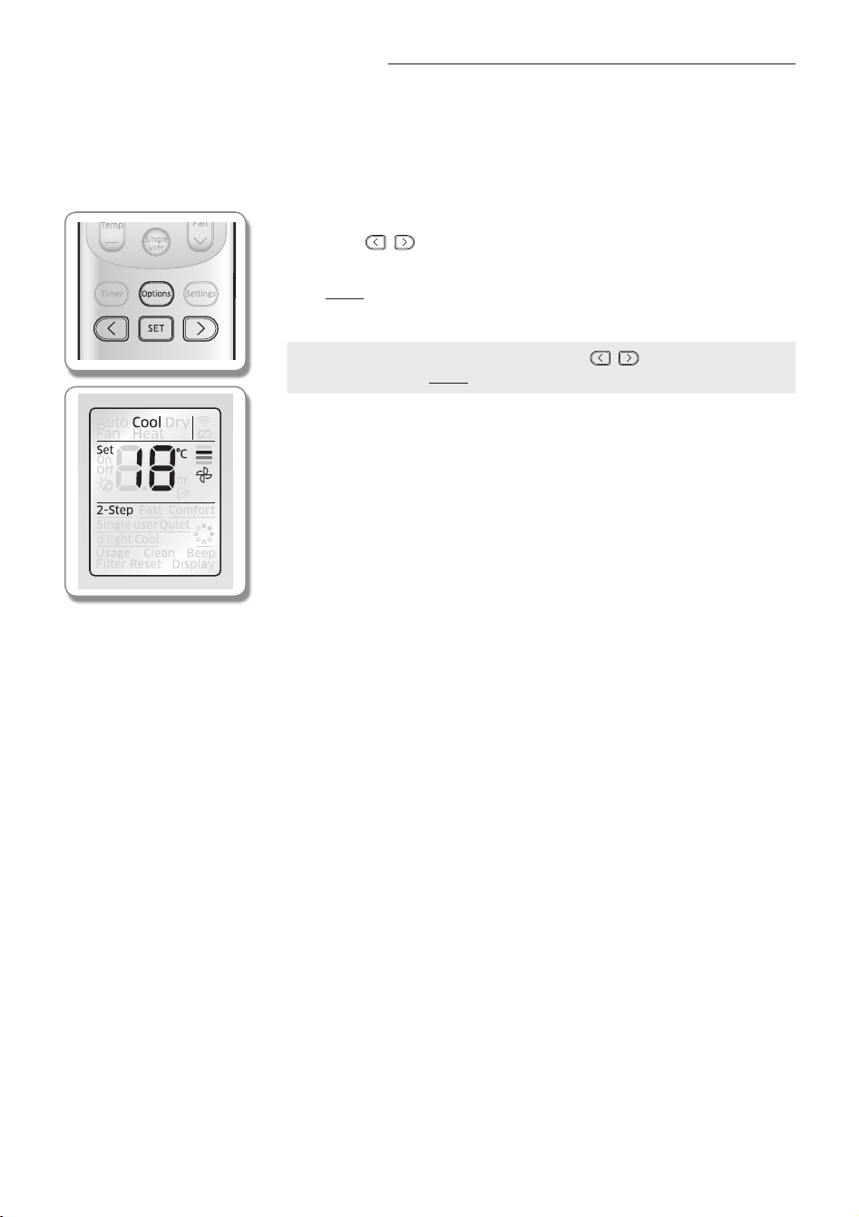
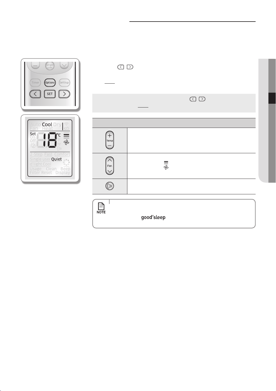
2-Step cooling function
2-Step Cooling function will set the air conditioner to cool the room quickly to reach the set temperature when the indoor
temperature is higher than the set temperature, and then the air conditioner will automatically operate in Dry mode when
indoor temperature reaches set temperature.
When the air conditioner is operating in Cool mode;
Remote controller display
1. Press the Options button.
2. Press the
, or Options button until (2-Step) indicator starts to blink.
3. Press the SET button to set the 2-Step Cooling function.
- (2-Step) (2-Step) indicator will be displayed on the remote controller display
and 2-Step Cooling function will begin.
Cancel
f Press the Options button Press the , or Options button to
make the (2-Step) indicator blink and press the SET button.
English-20
AR5000 ED CO_IB&IM_DB68-05069A_EN.indd 20 2015/3/20 16:14:50
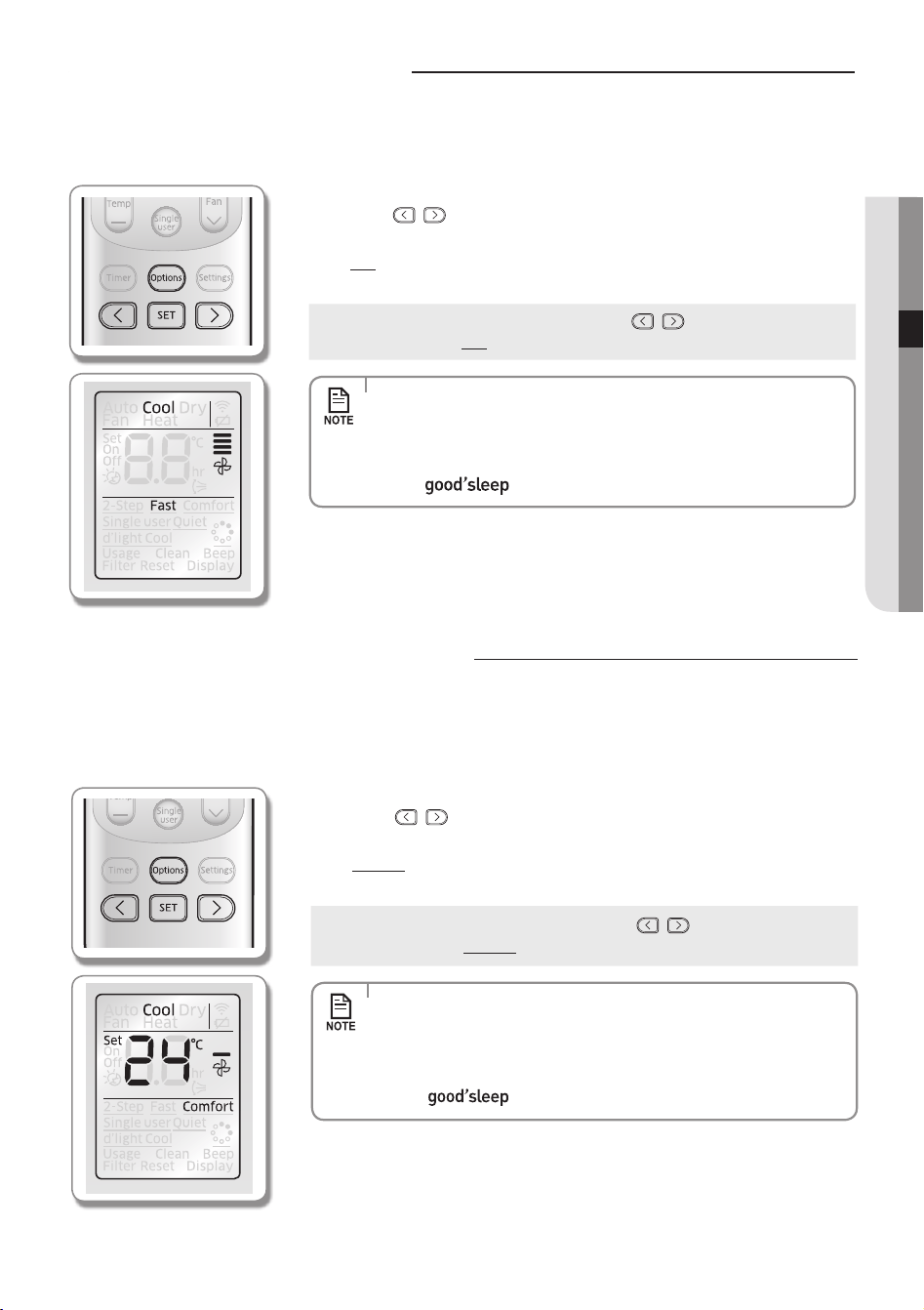
using the Fast function
using the Comfort function
You can set the Comfort function to provide mild cooling.
When the air conditioner is operating in Cool mode;
Remote controller display
1. Press the Options button.
2. Press the
, or Options button until (Comfort) indicator starts to blink.
3. Press the SET button to set the Comfort function.
- (Comfort) (Comfort) indicator will be displayed on the remote controller
display and Comfort function will begin.
Cancel
f Press the Options button Press the , or Options button to
make the (Comfort) indicator blink and press the SET button.
•Comfort function is only available in Cool mode.
•Vertical air swing can be adjusted.
•Set temperature can be adjusted, but fan speed cannot be adjusted.
•If the Comfort function is selected while 2-Step Cooling/ Fast / Single user/
Quiet/
function is on, corresponding function will be cancelled.
You can set the Fast function to provide fast and powerful cooling.
When the air conditioner is operating in Cool mode;
Remote controller display
1. Press the Options button.
2. Press the
, or Options button until (Fast) indicator starts to blink.
3. Press the SET button to set the Fast function.
- (Fast) (Fast) indicator will be displayed on the remote controller display and
Fast function will begin.
Cancel
f Press the Options button Press the , or Options button to
make the (Fast) indicator blink and press the SET button.
•Fast function is only available in Cool mode.
•Vertical air swing can be adjusted.
•Set temperature and fan speed cannot be adjusted.
•If the Fast function is selected while 2-Step Cooling/Comfort/Single user/
Quiet/
function is on, corresponding function will be cancelled.
English-21
OPTIOnS04
AR5000 ED CO_IB&IM_DB68-05069A_EN.indd 21 2015/3/20 16:14:51
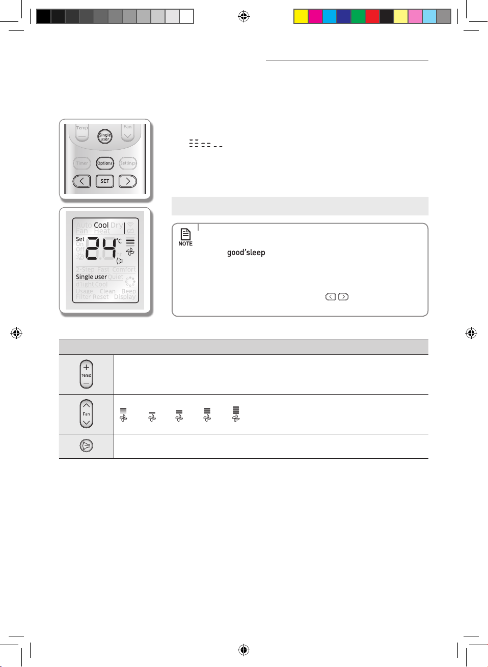
This function will reduce the energy usage while the air conditioner is operating in Cool mode.
When the air conditioner is operating in Cool mode;
Remote controller display
1. Press the Single user button.
- (Single user) indicator will be displayed on the remote controller display. Then
will be displayed on the set temperature indicator part for few
seconds and Single user function will begin.
- When the Single user function is on, vertical air swing will turn on automatically.
- If the current set temperature is lower than 24°C in Cool mode, it will be
automatically raised to 24 °C.
Cancel
f Press the Single user button once again.
•Single user function is only available in Cool mode.
•If the Single user function is selected while 2-Step Cooling/Fast/Comfort /
Quiet/
function is on, corresponding function will be cancelled.
•Vertical air swing will remain on even after the Single user function is
cancelled.
•Select or cancel the Single user function with the Options button.
- Press the Options button press the
, or Options button to
make (Single user) indicator blink and press the SET button.
additional options available in Single user function
You can adjust the set temperature by 1 °C within the range of 24 °C ~ 30 °C in Cool mode .
(Auto), (Low), (Med), (High), (Turbo) can be selected.
Vertical air swing can be selected.
using the Single user function
English-22
AR5000 ED CO_IB&IM_DB68-05069A_EN.indd 22 2015/3/20 16:14:51
using the Quiet function
You can reduce the noise generated from an indoor unit during Cool mode.
When the air conditioner is operating in Cool mode;
Remote controller display
1. Press the Options button.
2. Press the
, or Options button until (Quiet) indicator starts to blink.
3. Press the SET button to set the Quiet function.
- (Quiet)(Quiet) indicator will be displayed on the remote controller display and
Quiet function will begin.
Cancel
f Press the Options button Press the , or Options button to
make the (Quiet) indicator blink and press the SET button.
additional options available in Quiet function
You can adjust the set temperature by 1 °C within the range of
16°C ~ 30 °C.
Fan speed is set to (Auto).
Vertical air swing can be selected.
•Quiet function is only available in Cool mode.
•If the Quiet function is selected while 2-Step Cooling/Fast /Comfort/
Single user/ function is on, corresponding function will
be cancelled.
English-23
OPTIOnS04
AR5000 ED CO_IB&IM_DB68-05069A_EN.indd 23 2015/3/20 16:14:52
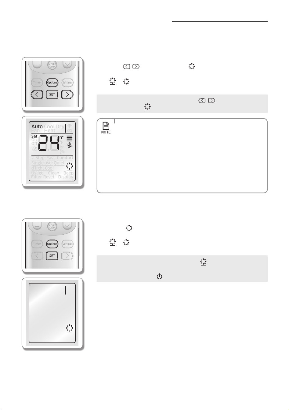
using the Virus Doctor function
This function will produce positive ions and supply them into the airow.
When the air conditioner is operating;
Remote controller display
1. Press the Options button.
2. Press the
, or Options button until ( ) indicator starts to blink.
3. Press the SET button to set the Virus Doctor function.
- (
)( ) indicator will be displayed on the remote controller display and
Virus Doctor function will begin.
Cancel
f Press the Options button Press the
, or Options button to
make the (
) indicator blink and press the SET button.
•Virus Doctor lamp will turn on when the Virus Doctor function turns
on, and it will turn o when the function is cancelled.
•Virus Doctor function can be selected while Auto/Cool/Dry/Fan mode
is on.
•Set temperature can be adjusted.
•There will not be much dierence on energy consumption and
operating noise when the Virus Doctor function is selected additionally
while the other function is on.
•When the Virus Doctor function is selected with other operation mode,
pressing the Power button will stop the operation.
When the air conditioner is not in operation;
1. Press the Options button.
2. When the (
) indicator blinks, press the SET button to select the Virus Doctor
function.
- (
)( ) indicator will be displayed on the remote controller display and
Virus Doctor function will begin.
Cancel
f Press the Options button to make the (
) indicator blink and press
the SET button.
f Press the Power(
) button.
English-24
AR5000 ED CO_IB&IM_DB68-05069A_EN.indd 24 2015/3/20 16:14:53
Setting the Beep sound
Beep sound from the indoor unit can be muted.
1. Press the Settings button.
2. Press the
, or Settings button until (Beep) indicator starts to blink.
3. Press the SET button to mute the beep sound.
- 3 seconds after setting Beep sound function, (Beep) indicator on the remote
controller display will disappear and Beep sound function will begin.
using the auto clean function
Auto clean function will minimise the moisture inside of the indoor unit. Activate this function to help provide you with
clean air.
When the air conditioner is operating;
Indoor unit display
1. Press the Settings button.
2. Press the
, or Settings button until (Clean) indicator starts to blink.
3. Press the SET button to set the Auto clean function.
- 3 seconds after setting auto clean function, (Clean) indicator on the remote
controller display will disappear and Timer indicator (
) will turn on the indoor
unit display. Auto clean function will be activated after the air conditioner stops
operating.
- Duration of the Auto clean function can be dierent depending on the previous
operation mode used.
Auto(cool), Cool, Dry mode : 30 minutes.
Fan mode: 15 minutes.
Cancel
f Press the Settings button Press the
, or Settings button to
make the (Clean) indicator blink and press the SET button.
•When the operation mode is set during Auto clean function is activated,
the air conditioner will operate in chosen operation mode and the Auto
clean function will be re-activated when the operation stops.
•Duringtheautocleanfunction,indoorfanwillcontinuetorunandair
ow blade will remain open to expel ambient air.
English-25
SETTIngS05
AR5000 ED CO_IB&IM_DB68-05069A_EN.indd 25 2015/3/20 16:14:54
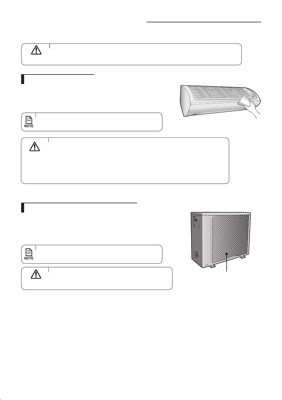
Cleaning the air conditioner
Cleaning the indoor unit
Cleaning the outdoor unit heat exchanger
f Clean the product with a tepid damp cloth.
f Remove the dust accumulated in the gap of the product with a soft
brush.
f When dust accumulates on the heat exchanger, it may decrease
cooling performance. Therefore, clean it regularly.
f Spray water to clean the dust.
•Ifitisdiculttocleantheoutdoorunitheatexchangeron
your own, contact service center.
•Contacttheservicecenterwhenyoucleantheindoorunit
heat exchanger because it needs to be disassembled.
Heat exchanger
(Illustration may dier slightly
depending on the models)
• Make sure to turn o the power of the indoor unit and cut-o
the power supply before cleaning the air conditioner.
CAUTION
•Donotcleanthedisplayusingalkalinedetergent.
•Donotusesulfuricacid,hydrochloricacid,organicsolvents
(such as thinner, kerosene and acetone etc.) to clean the
surface of the product or put any stickers on it.
They may damage the surface of the air conditioner.
CAUTION
•Becarefulwiththesharpedgesonthe
outdoor unit heat exchanger.
CAUTION
English-26
AR5000 ED CO_IB&IM_DB68-05069A_EN.indd 26 2015/3/20 16:14:54
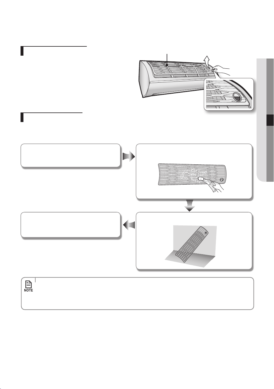
•CleantheAirlterevery2weeks.Cleaningtermmaydierdependingontheusageandenvironmental
conditions. In dusty area, clean it once a week.
•IftheAirlterdriesinaconned(orhumid)area,odorsmaygenerate.Ifitoccurs,re-cleananddryitina
well-ventilated area.
Removing the Air lter
There is a hole on the bottom right side of the lter. Put your
nger in that hole to get a grip on the lter and slightly push
it up to release the hooks from the bottom side. Then, pull it
down to remove the lter from the main body.
Cleaning the air lter
Washable foam based air lter captures large particles from the air. The lter is cleaned with a vacuum or by hand washing.
Remove the Air filter from the main body.
Insert the Air filter back in its original position. Dry the Air filter in a ventilated area.
Clean the Air filter with a vacuum cleaner or soft brush.
If dust is too heavy, rinse it with running water.
Air lter
English-27
OThErS06
AR5000 ED CO_IB&IM_DB68-05069A_EN.indd 27 2015/3/20 16:14:55
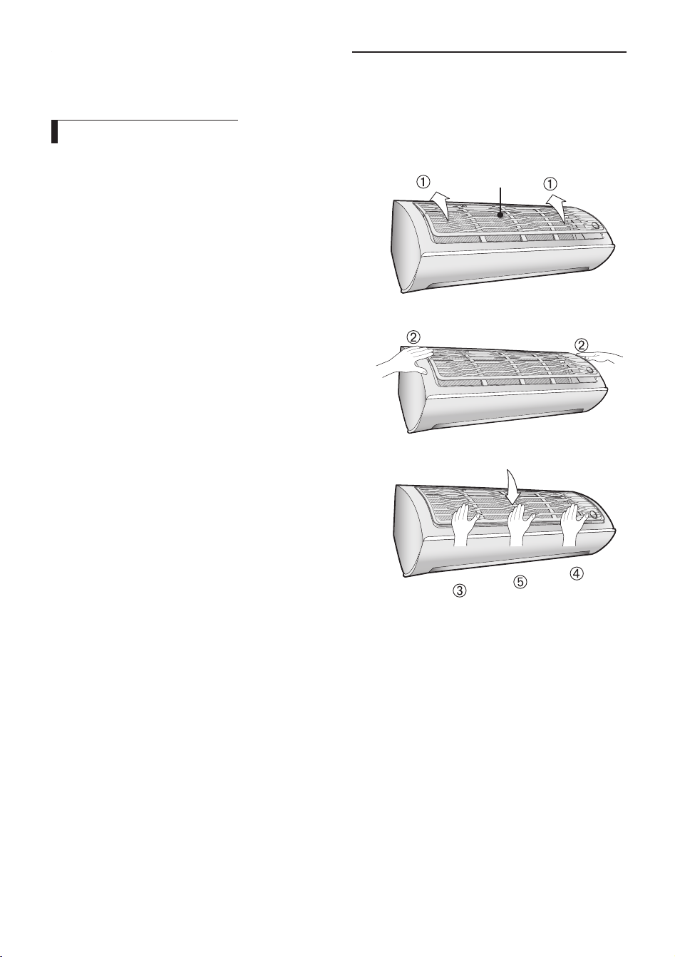
reassembling the air lter
1. Put the lter on the main body and insert the hooks which are
in the top of the Air lter into the the main body.
Air lter
2. There’s one hook in both side of the lter, press the surface of
the Air lter softly and get the hooks into the main body.
3. Press the bottom of the lter lightly to securely x the main
body.
Cleaning the air conditioner
English-28
AR5000 ED CO_IB&IM_DB68-05069A_EN.indd 28 2015/3/20 16:14:55
maintaining the air conditioner
If the air conditioner will not be used for an extended period of time, dry the air conditioner to maintain it in best condition.
1. Dry the air conditioner thoroughly by operating in Fan mode for 3 to 4 hours
and cut-o the power supply. There may be internal damage if moisture is left
in components.
2. Before using the air conditioner again, dry the inner components of the air
conditioner again by running in Fan mode for 3 to 4 hours. This helps remove
odors which may have generated from dampness.
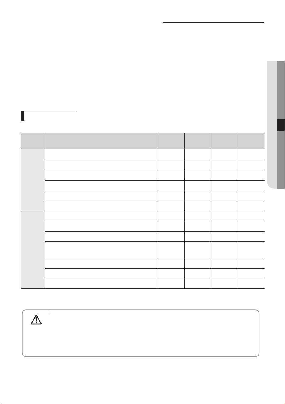
Periodical checks
Refer to the following chart to maintain the air conditioner properly.
Type Description
Every 2
weeks
Every 3
months
Every 4
months
Once a year
Indoor
unit
Clean the air lter (1)
Clean the condensate drain pan (2)
Thoroughly clean the heat exchanger (2)
Clean the cross fan (2)
Clean the condensate drain pipe (2)
Replace the remote controller batteries (1)
Outdoor
unit
Clean the heat exchanger on the outside of the unit (2)
Clean the heat exchanger on the inside of the unit (2)
Clean the electric components with jets of air (2)
Verify that all the electric components are rmly
tightened (2)
Clean the fan (2)
Verify that all the fan assembly is rmly tightened (2)
Clean the condensate drain pan (2)
: This check mark requires checking the indoor/outdoor unit periodically.
Follow the description to maintain the air conditioner properly.
(1) The described operations should be performed more frequently if
the area of installation is very dusty.
(2) These operations must always be performed by qualied personnel.
For more detailed information, see the installation part in the
manual.
CAUTION
English-29
OThErS06
AR5000 ED CO_IB&IM_DB68-05069A_EN.indd 29 2015/3/20 16:14:55
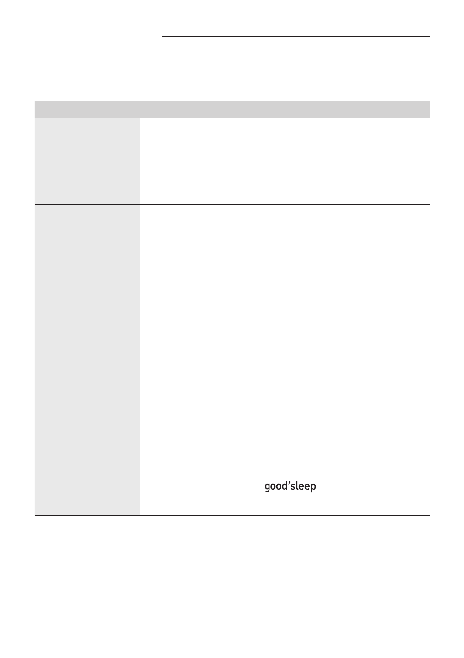
Troubleshooting
Refer to the following chart if the air conditioner operates abnormally. This may save
time and unnecessary expenses.
PROBLEM SOLUTION
The air conditioner
does not work at all.
•Checkpowerstatusandthenoperatetheairconditioneragain.
•Pluginorswitchonthecircuitbreakerandthenoperatetheair
conditioner again.
•EnsureIsolatorisswitchon.
•CheckifyouhavesettheOTimer.Operatetheairconditioner
again by pressing the Power button.
The temperature
adjustment is not
working.
•CheckifyouhaveselectedFan/Fastmode.Inthesemodes,desired
temperature is set to auto and you cannot adjust the temperature.
Cool air does not
come out of the air
conditioner.
•Checkifthesettemperatureishigher(duringCoolmode)thanthe
current temperature. Press the Temp + or - button on the remote
controller to change the set temperature.
•CheckiftheAirlterisblockedbydirt.Ifthereisalotofduston
the Air lter, cooling performance may decrease. Clean them
frequently.
•Checkiftheoutdoorunitiscoveredorinstalledneartheobstacle.
Take the cover o and take the obstacle away.
•Ifthedoorsorwindowsareopen,itmaycausebadcooling
performance.
Close the doors and windows.
•Checkiftheairconditionerhasjustbeenturnedonafterstopping
cooling operation. In this case, just a fan will run to protect the
outdoor unit compressor.
•Checkifthepipelengthistoolong.Whenthepipelengthexceeds
maximum allowable pipe length, cooling performance may
decrease.
Air ow adjustment
is not working.
•Checkifyouhaveselected
mode. In cool mode, you
cannot adjust the air ow direction.
English-30
AR5000 ED CO_IB&IM_DB68-05069A_EN.indd 30 2015/3/20 16:14:55

PROBLEM SOLUTION
Fan speed
adjustment is not
working.
•CheckifyouhaveselectedAuto/Dry/Fast/Comfort/
mode. In these mode, fan speed is set to Auto and you cannot
adjust the fan speed.
Remote controller is
not working.
•Checkifyourbatteriesaredepleted.
•Makesurenothingisblockingyourremotecontrollersensor.
•Checkthattherearestronglightingapparatusneartheair
conditioner. Strong light which comes from uorescent bulbs or
neon signs may interrupt the electric waves.
Timer function does
not set.
•CheckifyoupresstheSet button on the remote controller after
you have set the time.
The indicator
is blinking
continuously.
•PressthePower button or disconnect the power plug/switch
o the auxiliary power switch.
If the indicator is still blinking, contact the service center.
Odors permeate in
the room during
operation.
•Checkiftheapplianceisrunninginasmokyarea.Ventilatethe
room or operate the air conditioner in Fan mode for 1~2 hours.
(We do not use smelly components in the air conditioner.)
•ChecktheDrainshavebeenclearedRegularMaintenance.
Error is indicated. •Whenanindoorunitindicatorblinks,contactthenearestservice
center. Please ensure the error code is passed onto the service
center when booking the service call.
Noise is generated. •Dependingonthestatusoftheairconditionerusage,noisecan
be heard when refrigerant ow movement changes. It is normal.
Water is dropping
from the outdoor unit
piping connection.
•Watermaybegeneratedbecauseofthetemperaturedierence.
It is normal.
English-31
OThErS06
AR5000 ED CO_IB&IM_DB68-05069A_EN.indd 31 2015/3/20 16:14:55
Carefully follow the precautions listed below because they are essential to guarantee the safety of the equipment.
•Alwaysdisconnecttheairconditionerfromthepowersupplybeforeservicingitoraccessingitsinternalcomponents.
•Verifythatinstallationandtestingoperationsareperformedbyqualifiedpersonnel.
•Verifythattheairconditionerisnotinstalledinaneasilyaccessiblearea.
General information
Carefully read the content of this manual before installing the air conditioner and store the manual in a safe place in order
to be able to use it as reference after installation.
For maximum safety, installers should always carefully read the following warnings.
Store the operation and installation manual in a safe location and remember to hand it over to the new owner if the air
conditioner is sold or transferred.
This manual explains how to install an indoor unit with a split system with two SAMSUNG units.
The use of other types of units with dierent control systems may damage the units and invalidate the warranty.
The manufacturer shall not be responsible for damages arising from the use of non compliant units.
The manufacturer shall not be responsible for damage originating from unauthorized changes or the improper connection
of electric and requirements set forth in the “Operating limits” table, included in the manual, shall immediately invalidate
the warranty.
The air conditioner should be used only for the applications for which it has been designed: the indoor unit is not suitable
to be installed in areas used for laundry.
Do not use the units if damaged. If problems occur, switch the unit o and disconnect it from the power supply.
In order to help prevent electric shocks, res or injuries, always stop the unit, disable the protection switch and contact
SAMSUNG’s technical support if the unit produces smoke, if the power cable is hot or damaged or if the unit is very noisy.
Always remember to inspect the unit, electric connections, refrigerant tubes and protections regularly. These operations
should be performed by qualied personnel only.
The unit contains moving parts, which should always be kept out of the reach of children.
Do not attempt to repair, move, alter or reinstall the unit. If performed by unauthorized personnel, these operations may
cause electric shocks or res.
Do not place containers with liquids or other objects on the unit.
All the materials used for the manufacture and packaging of the air conditioner are recyclable.
The packing material and exhaust batteries of the remote controller(optional) must be disposed of in accordance with
current laws.
The air conditioner contains a refrigerant that has to be disposed of as special waste. At the end of its life cycle, the air
conditioner must be disposed of in authorized centers or returned to the retailer so that it can be disposed of correctly and
safely.
Installing the unit
IMPORTANT: When installing the unit, always remember to connect rst the refrigerant tubes, then the electrical lines.
Always disassemble the electric lines before the refrigerant tubes.
Upon receipt, inspect the product to verify that it has not been damaged during transport.
If the product appears damaged, DO NOT INSTALL it and immediately report the damage to the carrier or retailer (if the
installer or the authorized technician has collected the material from the retailer.)
Safety precautions
English-32
AR5000 ED CO_IB&IM_DB68-05069A_EN.indd 32 2015/3/20 16:14:55
After completing the installation, always carry out a functional test and provide the instructions on how to operate the air
conditioner to the user.
Do not use the air conditioner in environments with hazardous substances or close to equipment that release free ames to
avoid the occurrence of res, explosions or injuries.
To help prevent injury when accidentally touching the indoor unit fan, install the indoor unit at least 2.5m above the oor.
The air conditioner should be used only for the applications for which it has been designed : the indoor unit is not suitable
to be installed in areas used for laundry.
Our units must be installed in compliance with the spaces indicated in the installation manual to ensure either accessibility
from both sides or ability to perform routine maintenance and repairs. The units’ components must be accessible and that
can be disassembled in conditions of complete safety either for people or things.
For this reason, where it is not observed as indicated into the Installation Manual, the cost necessary to reach and repair the
unit (in safety, as required by current regulations in force) with slings, trucks, scaolding or any other means of elevation
won’t be considered in-warranty and charged to end user.
Power supply line, fuse or circuit breaker
Always make sure that the power supply is compliant with current safety standards. Always install the air conditioner in
compliance with current local safety standards.
Always verify that a suitable grounding connection is available.
Verify that the voltage and frequency of the power supply comply with the specications and that the installed power is
sucient to ensure the operation of any other domestic appliance connected to the same electric lines.
Always verify that the cut-o and protection switches are suitably dimensioned.
Verify that the air conditioner is connected to the power supply in accordance with the instructions provided in the wiring
diagram included in the manual.
Always verify that electric connections (cable entry, section of leads, protections…) are compliant with the electric
specications and with the instructions provided in the wiring scheme.
Always verify that all connections comply with the standards applicable to the installation of air conditioners.
Indoor unit
For Wi-Fi Air-conditioner installation, select indoor unit location near to wireless router.
In case Wi-Fi signal strength weakened , Smart APP may be disconnected depending on the Wi-Fi signal strength.
Where airow is not blocked.
Where cool air can be distributed throughout the room.
Install the refrigerant piping length and the height dierence of both indoor and outdoor units as indicated in the
installation diagram.
Wall that prevents vibration and is strong enough to hold the product weight.
Out of the direct sunlight .
1m or more away from the TV or radio (to prevent the screen from being distorted or noise from being generated).
As far away as possible from the uorescent and incandescent lights (so that the remote controller can be operated well).
A place where the air lter can be replaced easily.
Don't install directly above electronics equipment as leaking water may cause damage if not serviced. (eg. Computers, TV, etc).
Choosing the installation location
English-33
InSTaLLaTIOn07
AR5000 ED CO_IB&IM_DB68-05069A_EN.indd 33 2015/3/20 16:14:56
Outdoor Unit
Where it is not exposed to strong wind
Well ventilated and dustless places
Where possible keep out of sunlight and rain
Where neighbors are not annoyed by operation sound or hot air
Solid wall or support that prevents vibration and is strong enough to hold the product weight
Where there is no risk of ammable gas leakage
When installing the unit at a high place be sure to x the unit legs
3 m or more away from the TV or radio (to prevent the screen from being distorted or noise from being generated)
Install the unit horizontally
Place where drained water does not become any problem.
Place with no plants (especially climbing plants) and where small animal can not access.
Outdoor unit should not be place higher than 2.4 m or directly under eaves for accessibility for service and OH&S reasons.
•Avoidthefollowingplacestopreventmalfunctionoftheunit
- Where there is machine oil - Salty environment such as seaside areas
- Where sulde gas exists - Other special atmosphere areas
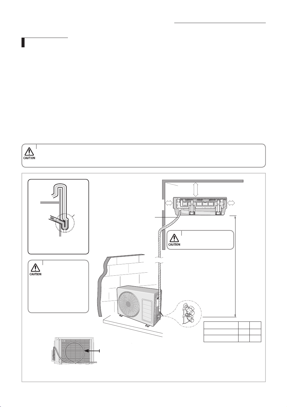
Choosing the installation location
125 mm or
more
100 mm or more
125 mm
or more
' L' meters maximum total
pipe length
Wrap the refrigerant pipes
and the drain hose with the
absorbent pad and vinyl
tape. Refer to page 51 for
further details.
You can select the direction of
draining (left or right).
'H' meters
maximum
total pipe
height
The appearance of the unit may be dierent from the diagram depending on the model.
Make at least one round: It will help reduce noise and vibration.
'L' m as maximum pipe length
and 3 m as minimum pipe length.
(It will reduce noise and vibration)
Outdoor
Unit
Indoor
Unit
Outer wall
Cut insulation to
have rainwater
drained
Make an U-trap(A) on the
pipe (which is connected
to the indoor unit) at outer
wall and cut the bottom
part of the insulation (about
10mm) to prevent rainwater
from getting inside through
the insulation. However,
be careful not to damage
the pipe.
A
model L h
09/12
15 7
18/24
30 15
English-34
AR5000 ED CO_IB&IM_DB68-05069A_EN.indd 34 2015/3/20 16:14:56
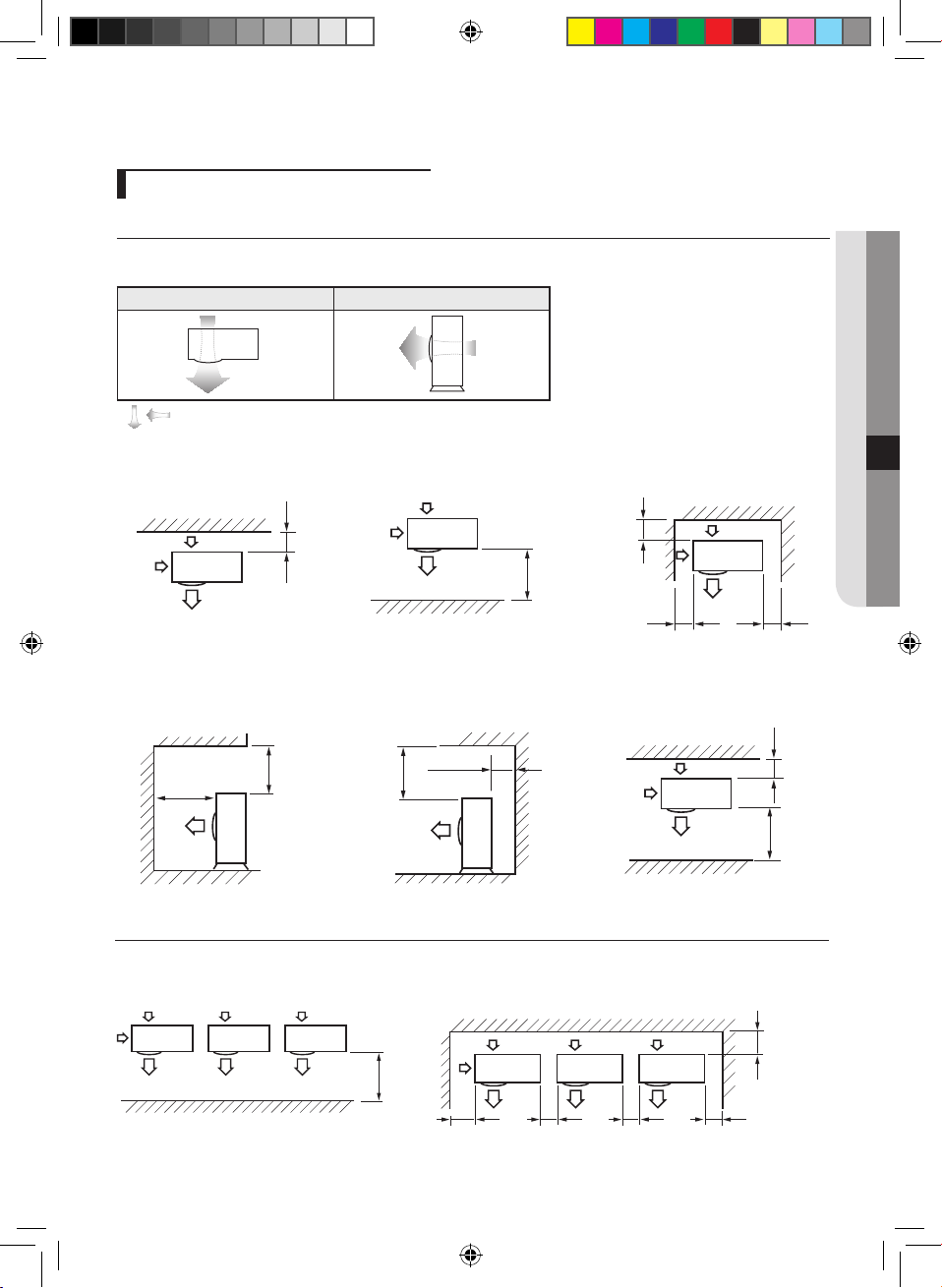
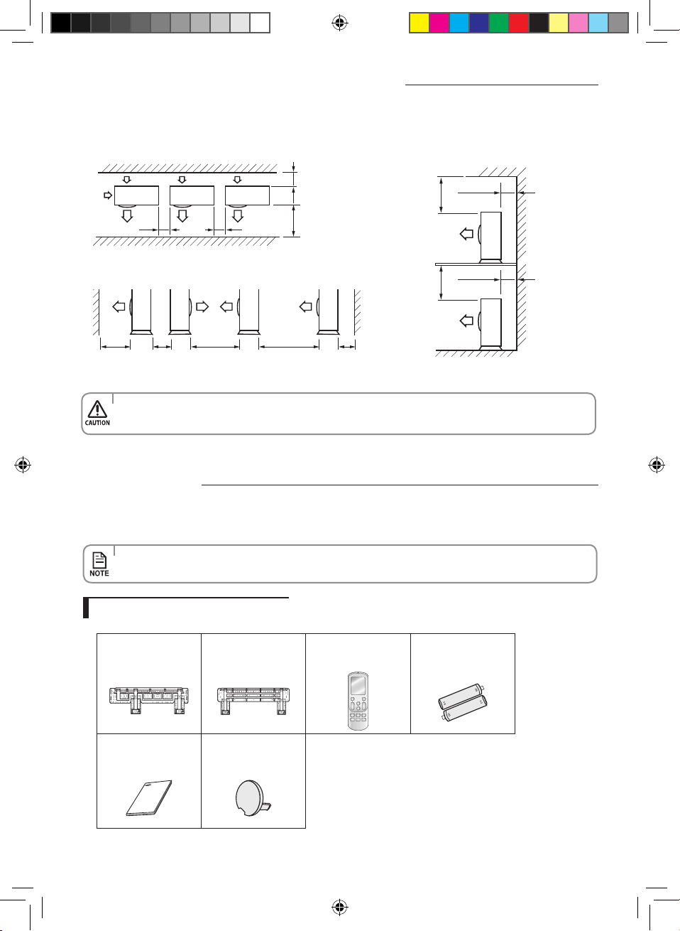
Space Requirements for Outdoor Unit
When installing 1 outdoor unit
300 or more
When the air outlet is opposite the
wall
1500 or more
When the air outlet is towards the
wall
300 or more
150 or more 600 or more
When 3 sides of the outdoor unit are
blocked by the wall
1500 or more
2000 or more
The upper part of the outdoor unit
and the air outlet is towards the wall
500 or more
300 or more
The upper part of the outdoor unit
and the air outlet is opposite the
wall
When the walls are blocking front
and the rear side of the outdoor unit
300 or
more
1500 or
more
Top view Side view
Air outlet Air intake
Air intake
Air outlet
Figure Description
, Air flow direction.
(Unit : mm)
When installing more than 1 outdoor unit
(Unit : mm)
1500 or more
When the air outlet is towards the wall When 3 sides of the outdoor unit are blocked by the wall
300 or more
300 or more 600 or more 600 or more 600 or more
English-35
InSTaLLaTIOn07
AR5000 ED CO_IB&IM_DB68-05069A_EN.indd 35 2015/3/20 16:14:56
When the upper part of the outdoor unit and
the air outlet is opposite the wall
When the walls are blocking front and the rear side of the outdoor
units
When front and rear side of the outdoor unit is towards the wall
500 or more
300 or more
500 or more
300 or more
300 or
more
1500 or
more
600 or more 600 or more
1500 or
more
600 or
more
3000 or
more
200 or
more
3000 or
more
•Ifinstallationisdoneininappropriatespace,unitmaygeneratesoundandcausebadeectontheproduct.
•Installationmustbedoneinlevelandinaplacewherevibrationwillnotcauseanyeect.
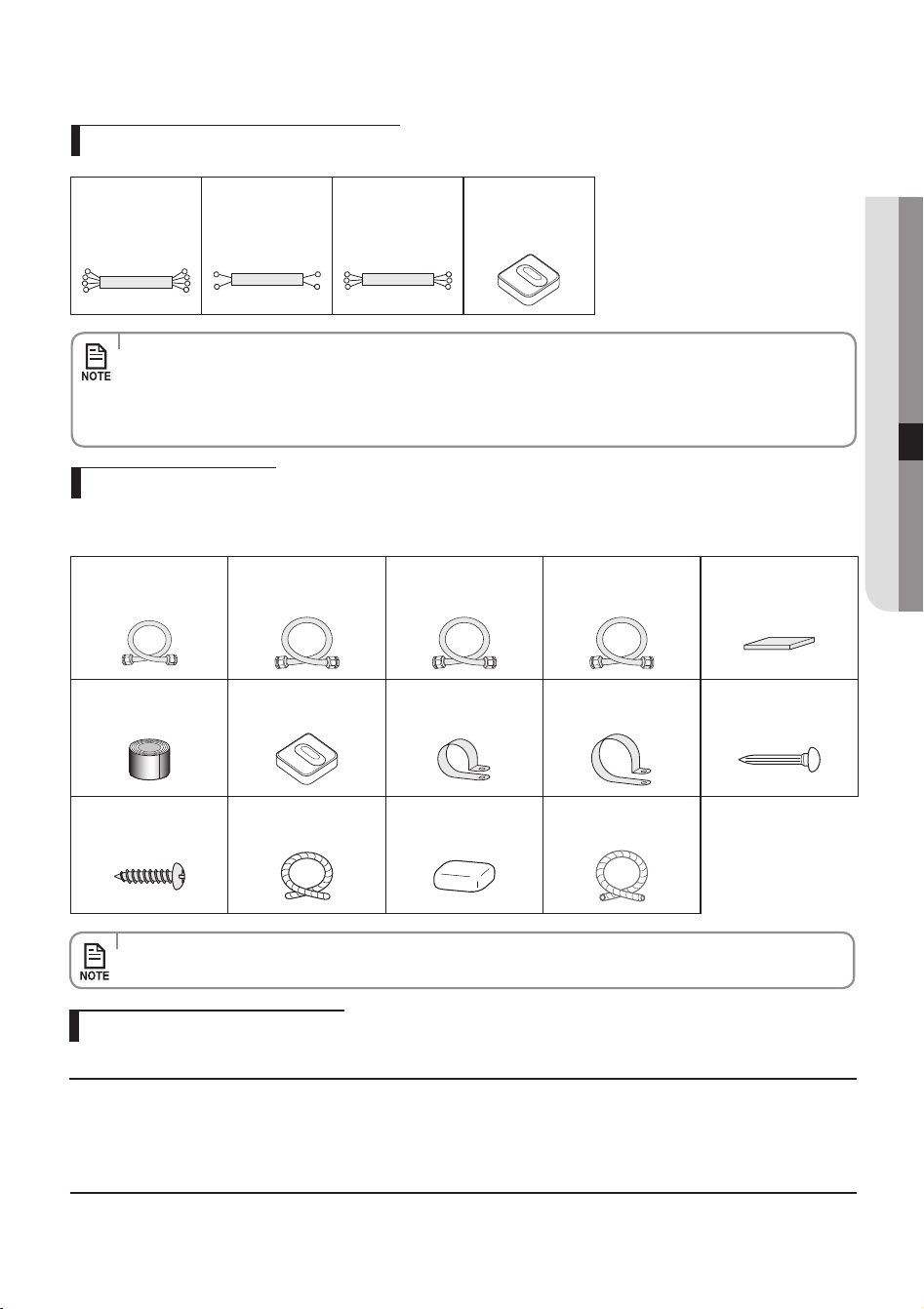
The following accessories are supplied with the air conditioner:
•Thenumberofeachaccessoryisindicatedinparentheses.
Accessories in the indoor unit case
accessories
(Unit : mm)
Installation Plate (1)
09/12(03 frame)
Installation Plate (1)
18/24 (05 frame)
Remote controller (1)
Batteries for Remote
controller (2)
User’s & Installation
Manual (1)
Cap Screws(2)
Choosing the installation location
English-36
AR5000 ED CO_IB&IM_DB68-05069A_EN.indd 36 2015/3/20 16:14:57
Accessories in the outdoor unit case
•Thearenutsareattachedtotheendofeachpipeofanevaporatororaserviceport.
Use the nuts when connecting the pipes.
•Theassemblycableisoptional.Ifitisnotsupplied,usethestandardcable.
•Thedrainplugandrubberlegareonlyincludedwhentheairconditionerissuppliedwithouttheassembly
pipe as seen in the picture below.
Tools required for installation
General Tools
•VacuumPump(Backwardowingprevention)•ManifoldGauge•StudFinder
•TorqueWrench•PipeCutter•Reamer•PipeBender•SpiritLevel
•ScrewDriver•Spanner•Drill•LWrench•MeasuringTape
Tools for test operations
•Thermometer•ResistanceMeter •Electroscope
Optional accessories
The following connection accessories are optional. If they are not supplied, you should obtain them before installing the air
conditioner.
•Iftheseaccessoriesaresupplied,theywillbeintheaccessorybox.
Insulated assembly
Pipe, Ø6.35 mm (1)
Insulated assembly
Pipe, Ø9.52 mm (1)
09/12
Insulated assembly
Pipe, Ø12.70 mm (1)
18
Insulated assembly
Pipe, Ø15.88 mm (1)
24
PE T3 Foam Tube
Insulation (1)
Vinyl Tapes (2)
rubber Legs (4)
Pipe Clamps a (3)
Pipe Clamps B (3) Cement nails (6)
m4 x 25
Tapped Screws (6)
Drain hose,
length 2 m (1)
Putty 100 g (1)
Foam Insulation(1)
4-wire
Assembly Cable (1)
09/12
2-wire
Assembly Cable (1)
18/24
3-wire
Assembly Cable (2)
18/24
Rubber Leg (4)
English-37
InSTaLLaTIOn07
AR5000 ED CO_IB&IM_DB68-05069A_EN.indd 37 2015/3/20 16:14:57
Fixing the installation plate
You can select the direction of the drain hose depending on where you want to install the indoor unit. Therefore before xing
the installation plate to a wall or a window frame, you must determine the position of the 65mm hole through which the cable,
pipe and hose pass to connect the indoor unit to the outdoor unit.
When facing the wall, the pipe and cable can be connected from the:
3. Determine the position of the pipe and drain hose hole as seen in the picture and drill the hole with an inner diameter
of 65mm so that it slants slightly downwards.
Wall
<20mm
Plastic
Anchor
4. Fix the indoor unit.
If you x the indoor unit on a wall
(1) Fix the installation plate to the wall giving attention to the weight of the indoor unit.
If you x the indoor unit on a window frame
(1) Determine the positions of the wooden uprights to be attached to the window frame.
(2) Attach the wooden uprights to the window frame giving attention to the weight of the indoor unit.
(3) Attach the installation plate to the wooden upright using tapping screws.
If you x the indoor unit on a gypsum board
(1) Use stud nder to nd out locations of the studs.
(2) Fix the plate hanger on two studs.
•Ifyoumounttheplatetoaconcretewallusingplasticanchors,makesurethatgaps
between the wall and the plate, created by projected anchor, is less than 20mm.
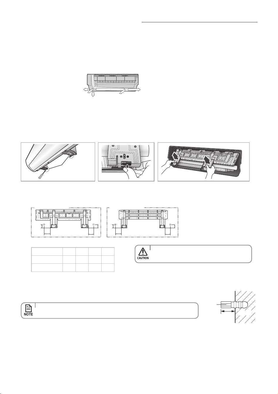
1. Disassemble the cover panel as described in page 39~40.
2. Remove the Hanger plate from the indoor unit.
(1) Unscrew 2 screws that xes the Hanger plate to the indoor unit.
(2) Push the hooks (on the bottom part of the indoor unit) up to release the installation plate from the hooks that holds it.
(3) Pull the installation plate to release it completely from the indoor unit.
Screw(M4x10)
Screw
A
C
B
D
D
Direction of pipe
•Right(A)
•Left(B)
•Underside_right(C)
•Rear_rightorleft(D)
•Makesuretodrillonlyoneholeafterchoosing
the direction of the pipe.
(Unit : mm)
Model A B C D
09/12
36 120 81 36
18/24
33 110 110 33
B
A
D
C
B
A
D
C
Pipe hole (Ø65 mm)
Pipe hole (Ø65 mm)
English-38
AR5000 ED CO_IB&IM_DB68-05069A_EN.indd 38 2015/3/20 16:14:58
assembling the hanger screw
Use 2 screws to x the indoor unit with hanger plate as shown in the picture.
•Makesurethatawallcanwithstandtheweightoftheproduct.Ifyouinstalltheproductinaplacewhereitisnot
strong enough to withstand the product weight, the unit could fall and cause injury.
•Searchforotherspotsiftherearelessthantwostuds,orthedistancebetweenthestudsaredierentfromthe
plate hanger.
•Fixtheinstallationplatewithoutincliningtooneside.
Disassembling/assembling the Cover panel for indoor unit installation
Please scan
this QR code for detail
video of indoor unit
installation.
Screw
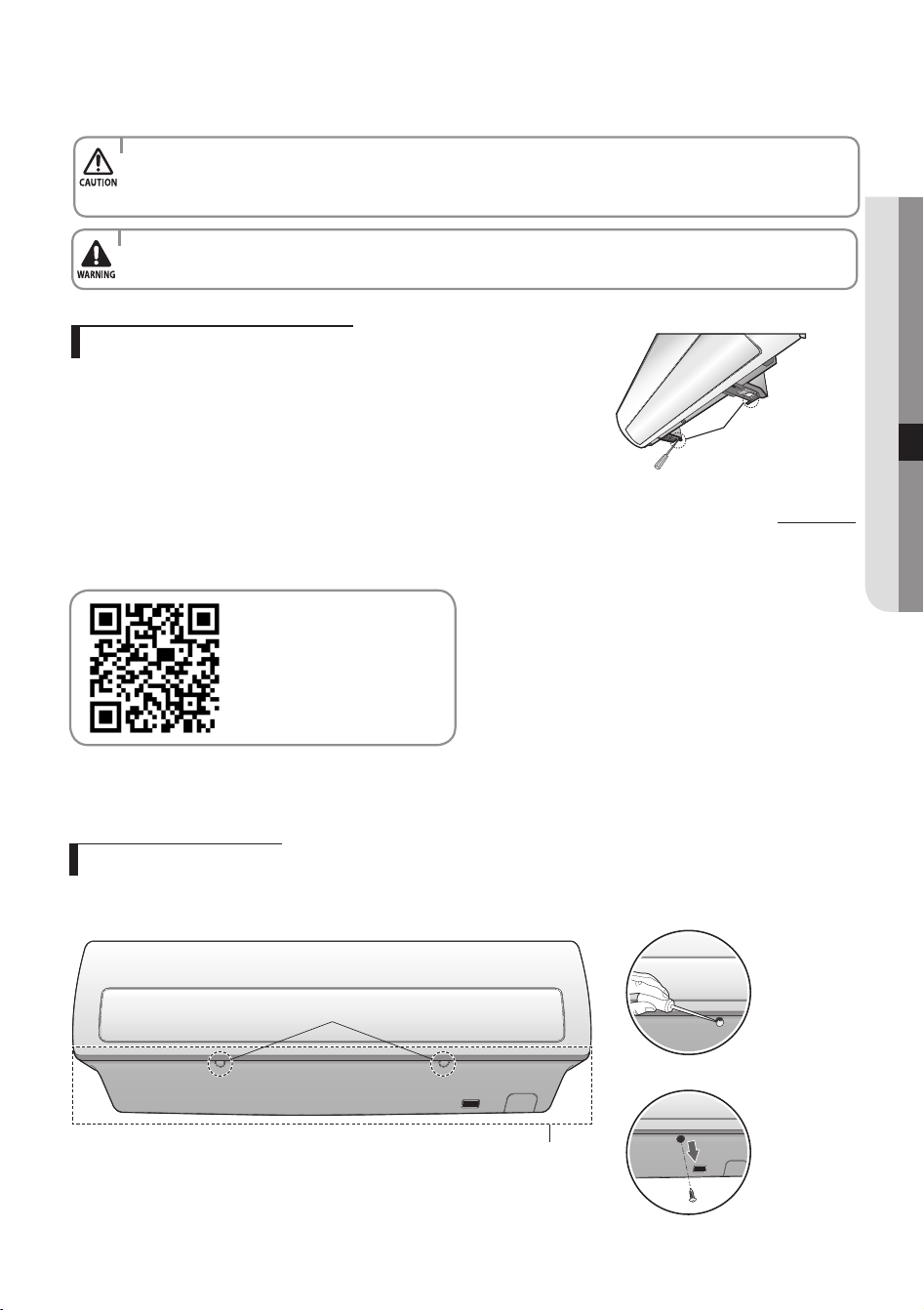
In order to install the indoor unit, you must disassemble the cover panel rst. Please proceed following
instructions to disassemble and assemble the cover panel. Hooks (on the cover panel) may get damaged if you
apply excessive force as you disassemble and assemble the cover panel. Please follow the following instructions.
removing the screws
Cover panel is assembled on the bottom part of the indoor unit (as shown in the illustration) and it is fastened
with screws. Remove the Cap screw rst and unfasten the screws so that you can disassemble the cover panel.
Cap Screw
<Remove the Cap screw>
<Unfasten the screw>
Cover Panel
English-39
InSTaLLaTIOn07
AR5000 ED CO_IB&IM_DB68-05069A_EN.indd 39 2015/3/20 16:14:59
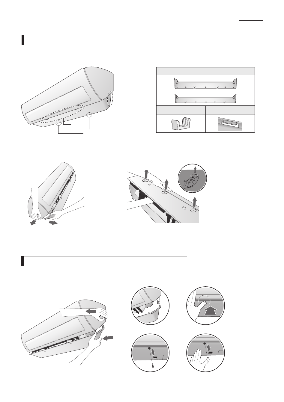
f Removing the hooks on the side
f Removing the hooks on the central part
Caution (fragile)
- Gently press the both side of the cover
panel inwards (①) and release the hooks
on both sides(②).
Caution (fragile)
- Use both hands
- Release each hook by pushing it up at an angle.
②
①
assembling the Cover panel (after mounting the indoor unit)
To assemble the Cover panel, proceed in reverse order of disassembling.
Use both hands for assembling and be extra careful not to damage the pipes and drain hose.
Lock the side, center, and bottom hooks in this sequence. Tighten the bottom panel with the screws, and close
the screw holes with their cap.
removing the Cover panel (Before mounting the indoor unit)
The bottom panel ts the main body using the side, center, and bottom hooks as shown. Unlock the side hooks
rst, and then unlock the center and bottom hooks.
Check the location of the hooks before removing the cover panel.
f Location of the hooks on the central part
For specic Hook location and quantity, please
refer to cover panel with indicating arrows
based on physical goods.
number and location of the hooks
Center hook
Bottom hook
<Lock the side hook>
<Fasten the screw>
<Lock the bottom hook>
<Assemble the Cap screw>
Side
hooks
Center
hooks
Bottom hooks
Disassembling/assembling the Cover panel for indoor unit installation
English-40
AR5000 ED CO_IB&IM_DB68-05069A_EN.indd 40 2015/3/20 16:15:01
Connecting the assembly cable
Cable specication
Connecting the cable
Electrical work
(1) For electrical and earth works, comply with the ‘technical standards of electrical installations’ and the the ‘wiring
regulations’ of the Local wiring regulations.
(2) Tightentheterminalblockscrewto1.2~1.8N•m(12~18kgf•cm).
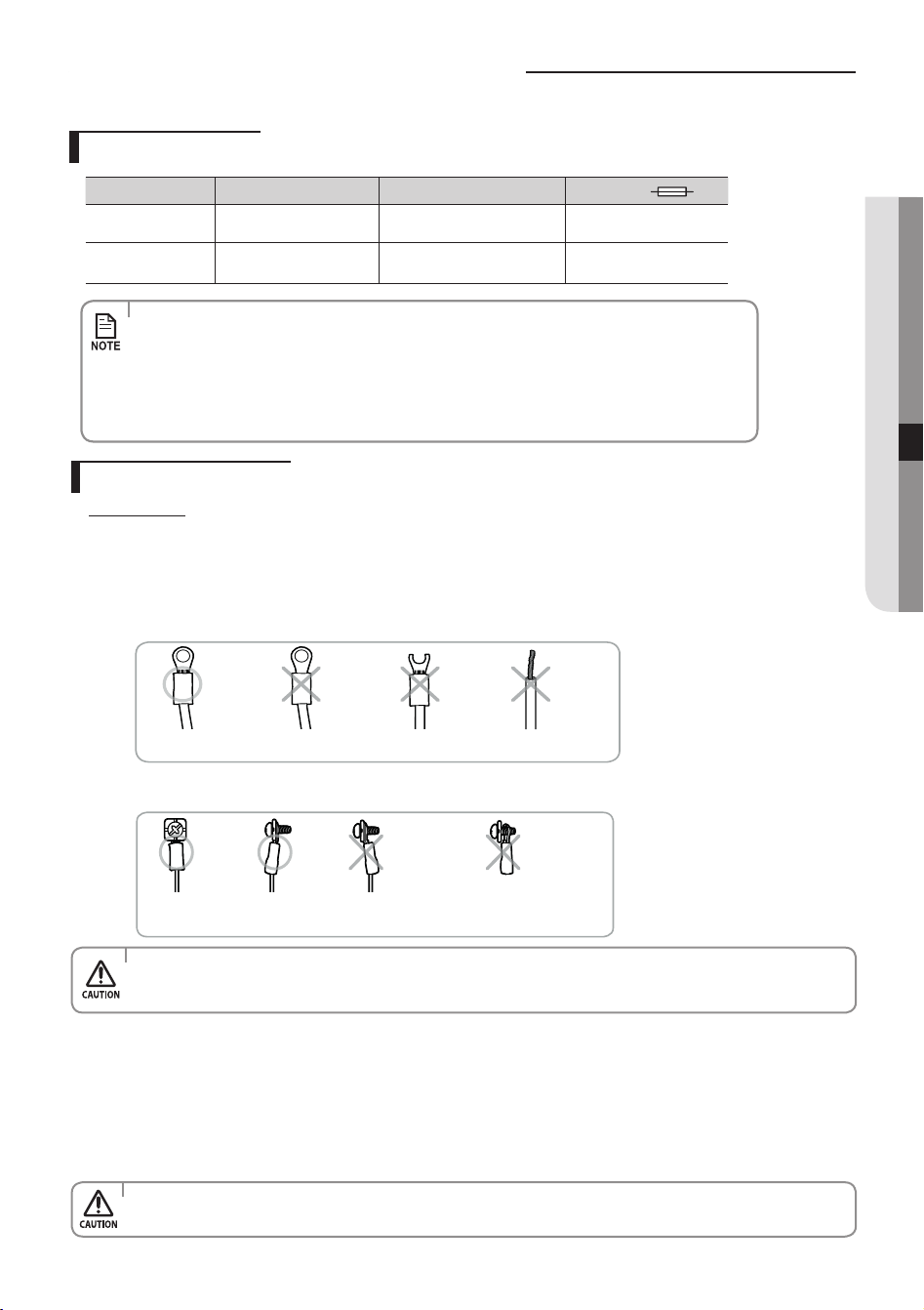
(3) Precautions when connecting terminal blocks of the indoor unit
Before connecting, make sure the connecting part of the terminal socket is facing upwards.
Upside down
The terminal
socketis damaged.
There is no ring terminalto
cover the wire.
There must be no space between the terminal and the screw when connected.
- Any remaining space may become a re hazard due to overheating of the electrical contact.
The terminal socket
is upside down.
Either the screw is not fitted
properly or there is a space
between the screw and the
ring terminal.
•Fortheterminalblockwiring,useawirewitharingterminalsocketonly.
Regular wires without a ring terminal socket may become a re hazard due to overheating of the electrical
contact during a wiring work.
•Donotconnecttwoormoredierentcablestoextendthelength.Itmaycausere.
1. Extend the assembly cable if necessary.
When you install the unit, make rst refrigerant connections and then electrical connections.
Connect the air conditioner to grounding system before performing the electrical connection.
If unit is uninstalled, rst disconnect electrical cables, then refrigerant connections.
If the outdoor unit is more than 8 meters away from the indoor unit, you must extend the cable. The maximum length of the
cable is 15(09/12) / 30 (18/24) meters.
Model Power cable Interconnection cable Type GL
09/12
3GxAWG16 SJT
(3G1.0mm
2
H05VV-F)
4G1.5mm² H07RN-F 20A
18/24
3G2.5mm² H07RN-F
3G1.0mm² H07RN-F
2x0.75mm² H05RN-F
25A
•Connectthepowercabletotheauxiliarycircuitbreaker.Ifeverypolefailstoconnecttothe
power supply, it must be incorporated in a wire with a contact opening of ≥3 mm.
•Useshieldcable(Category5;lessthan50pF/m)fornoisyenvironmentalsite.
•Powersupplycordsofpartsofappliancesforoutdooruseshallnotbelighterthan
polychloroprene sheathed exible cord. (Code designation IEC: 60227 IEC 53/CENELEC: H05VV-F,
IEC: 60245 IEC 66/CENELEC: H07RN-F, IEC: 60245 IEC 57/CENELEC: H05RN-F)
English-41
InSTaLLaTIOn07
AR5000 ED CO_IB&IM_DB68-05069A_EN.indd 41 2015/3/20 16:15:02
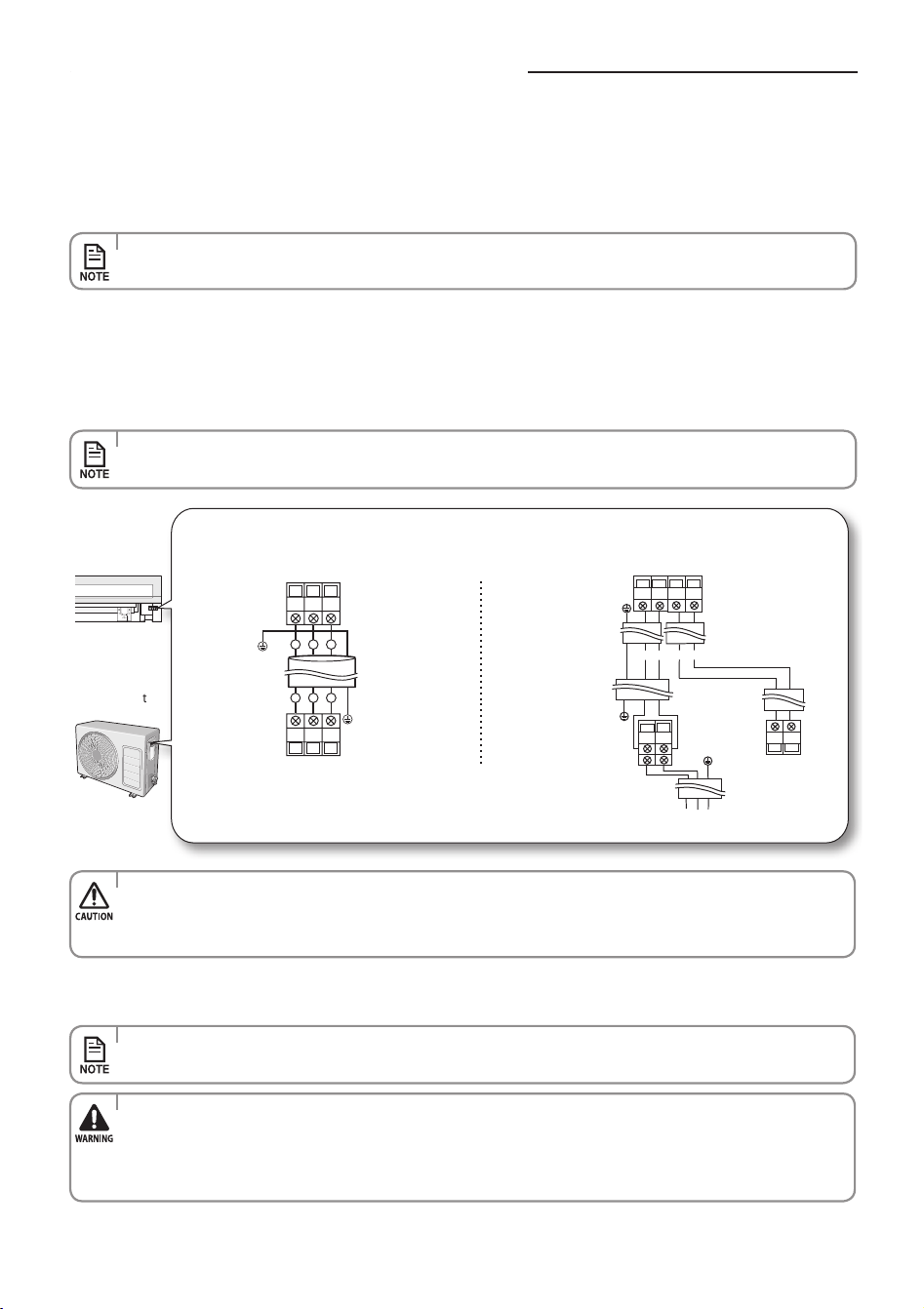
2 . Open the cover panel.
3 . Remove the screw securing the connector cover.
4 . Pass the assembly cable through the rear of the indoor unit and connect the assembly cable to terminals.
(Refer to the picture below)
•Eachwireislabeledwiththecorrespondingterminalnumber.
5 . Pass the other end of the cable through the 65 mm hole in the wall.
6 . Close the connector cover by tightening the screw carefully.
7 . Close the cover panel.
8 . Remove the terminal board cover on the side of the outdoor unit.
9. Connect the cables to the terminals as seen in the picture.
•Eachwireislabeledwiththecorrespondingterminalnumber.
Indoor unit
Outdoor unit
•Alsocircularterminalmustbematchedwithscrewsizeinterminalblock.
•Afterconnectingthecables,makesureterminalnumbersontheindoor/outdoorunitmatches.
•PleaseensurethatPower&Communicationcablesareseparated,theymustnotbeinthesamecable.
10. Connect the grounding conductor to the grounding terminals.
11. Close the terminal board cover by tightening the screw carefully.
•InRussiaandEurope,consultwiththesupplyauthoritytodeterminethesupplysystemimpedancebefore
installation.
•Connectthewiresrmlysothatwirescannotbepulledouteasily.
(If they are loose, it could cause burn-out of the wires.)
•Connectthewiresaccordingtocolorcodes,referringtothewiringdiagram.
•Thepowercableandtheinterconnectioncableshouldbeselectedaccordingtothespecicationinpage41.
Connecting the assembly cable
1 2
N(1)
N(1)
1 2
21
N1
2
1
1
N(1)
N(1)
1(L)
2(N)
F1
F2
1(L)
2(N)
F1
F2
F1
F2
L
N
Indoor unit
Outdoor unit
Indoor unit
Outdoor unit
Ground wire
(Green/Yellow)
Ground wire
(Green/Yellow)
Ground wire
(Green/Yellow)
Ground wire
(Green/Yellow)
09/12
18/24
English-42
AR5000 ED CO_IB&IM_DB68-05069A_EN.indd 42 2015/3/20 16:15:02
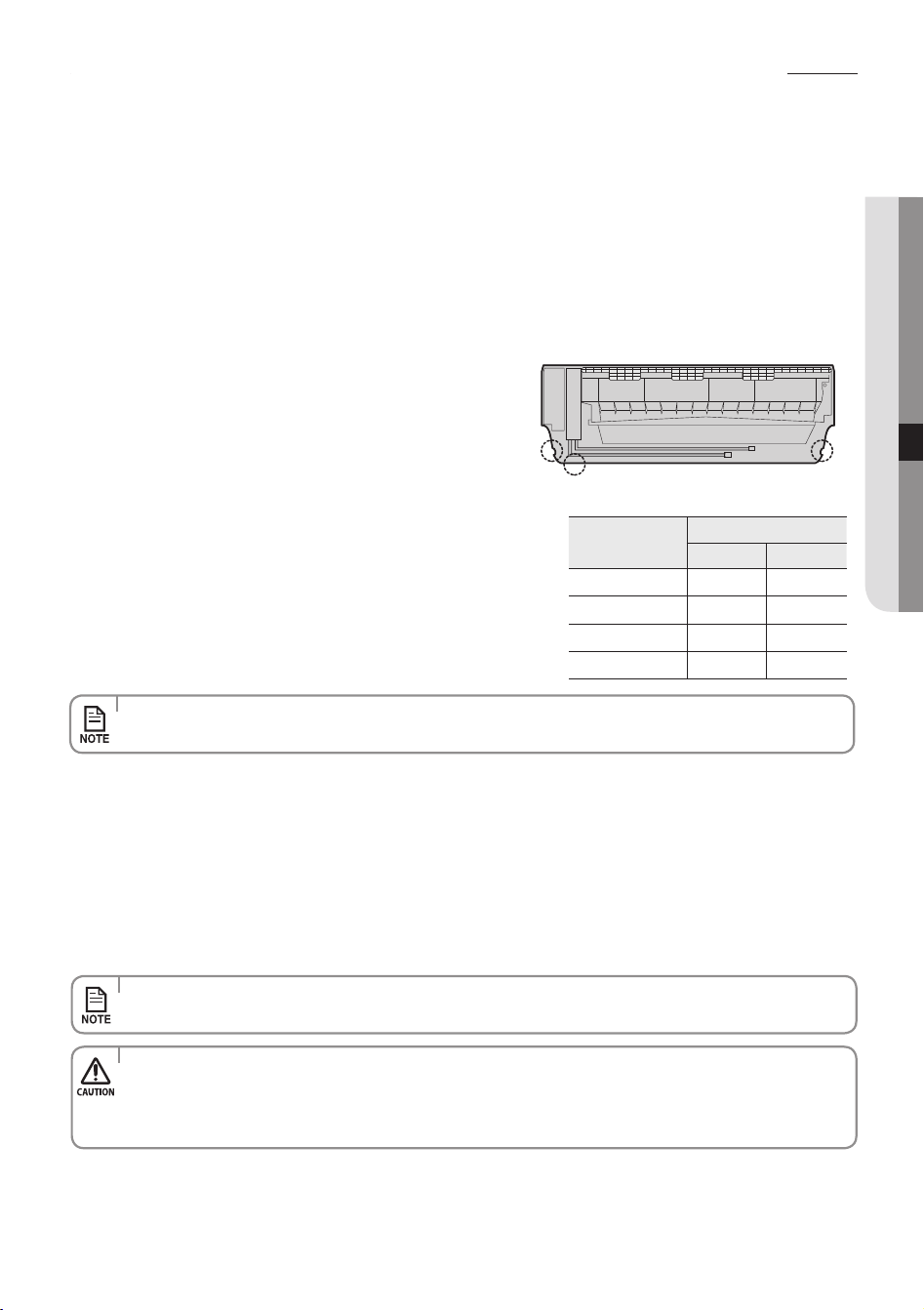
Installing and connecting the assembly pipe of the indoor unit
1. Cut out the appropriate knock-out piece (A or B) on the rear of the
indoor unit unless you connect the pipe directly from the rear.
2. Smooth the cut edges.
3. Remove the protection caps of the pipes and connect the assembly
pipe to each pipe. Tighten the nuts rst with your hands, and then with
a torque wrench, applying the following torque:
Connect indoor and outdoor units with eld-supplied copper pipes by means of are connections. Use insulated seamless
refrigeration grade pipe only, (Cu DHP type according to ISO1337), degreased and deoxidized, suitable for operating pressures
of at least 4200 kPa and for burst pressure of at least 20700 kPa. Under no circumstances must sanitary type copper pipe be
used.
There are 2 refrigerant pipes of dierent diameters:
•Thesmalleroneisfortheliquidrefrigerant
•Thelargeroneisforthegasrefrigerant
A short pipe is already tted to the air conditioner. You may
need to extend the pipe using the assembly pipe (optional).
The connection procedure for the refrigerant pipe varies
according to the exit position of the pipe when facing the wall:
•Right(A)
•Left(B)
•Underside(C)
•Rear
Outer Diameter
Torque
N•mkgf•cm
ø6.35 mm 14~18 140~180
ø9.52 mm 34~42 350~430
ø12.70 mm 49~61 500~620
ø15.88 mm 68~82 690~830
•Ifyouwanttoshortenorextendthepipes,refertopage44~45.
4. Cut o the remaining foam insulation.
5. If necessary, bend the pipe to t along the bottom of the indoor unit.
Then pull it out through the appropriate hole.
The pipe should not project from the rear of the indoor unit.
The bending radius should be 100 mm or more.
6. Pass the pipe through the hole in the wall.
7. For further details on how to connect to the outdoor unit and evacuate the air, refer to page 48~49.
•Tightenthearenutwithtorquewrenchaccordingtospeciedmethod.
If the are nut is over-tightened, the are may break and cause refrigerant gas leakage.
•DONOTWALLUPTHEPIPECONNECTION!
All refrigerant pipe connection must be easy accessible and serviceable.
•Thepipewillbeinsulatedandxedpermanentlyintopositionafternishingtheinstallationandthegasleaktest;
refer to page 51 for further details.
B
A
C
English-43
InSTaLLaTIOn07
AR5000 ED CO_IB&IM_DB68-05069A_EN.indd 43 2015/3/20 16:15:02
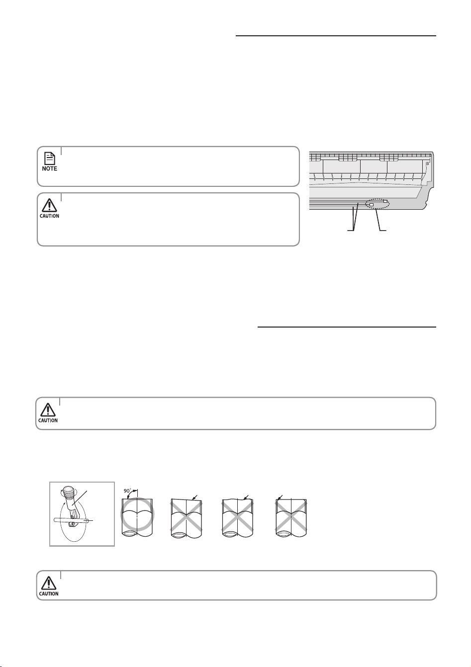
Evacuating the indoor unit
•TheremainingairintheRefrigerationcycle,whichcontainsmoisture,
may cause malfunction on the compressor.
•Alwayscontacttheservicecenteroraprofessionalinstallationagency
for product installation.
•Topreventdirtorforeignsubstancesfromgettingintothepipes
during installation, do NOT remove the caps completely until you are
ready to connect the pipes.
The length of the pipe can be:
•Extendedupto:seetablepage34
•Shortenupto:seepage34
If you need a pipe longer than 7.5 meters:
•Youmustaddrefrigeranttothepipes;otherwise,theindoorunitmayfreeze.
Cutting or extending the pipe
1. Unscrew the caps at the end of each pipe.
All inert gas exhausts from the indoor unit.
The indoor unit is supplied with inert gas (nitrogen).
Before installing the unit, check if nitrogen gas ow out of indoor unit.
If this one isn’t true, DO NOT INSTALL THE UNIT since leakage could be inside the indoor unit.
Unscrew the
caps
Pipes
1. Make sure that you have all the required tools (pipe cutter, reamer, aring tool and pipe holder).
2. If you want to shorten the pipe, cut it using a pipe cutter, ensuring that the cut edge remains at 90° with the side of the
pipe (see below examples of correct and incorrect cut edges).
Oblique Rough Burr
Pipe
cutter
Pipe
3. To prevent a gas leak, remove all burrs at the cut edge of the pipe using a reamer.
•Facethepipedownwhileremovingtheburrstomakesurethatburrsdonotgetintothepipe.
English-44
AR5000 ED CO_IB&IM_DB68-05069A_EN.indd 44 2015/3/20 16:15:03
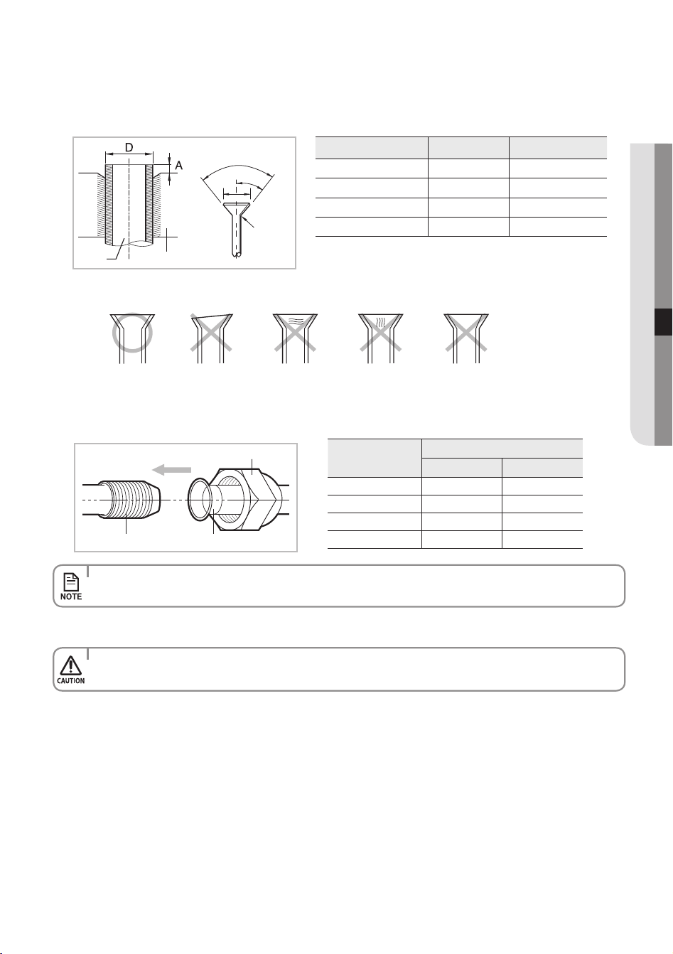
Indoor outlet pipe Connecting pipe
Flare nut
5. Check if you ared the pipe correctly (see examples of incorrectly ared pipes below).
6. Align the pipes to connect them easily. Tighten the are nuts rst with your hands, and then with a torque wrench,
applying the following torque:
7. For further details on how to connect to the outdoor unit and evacuate the air, refer to page 48~49.
Correct
Uneven
Thickness
Cracked
Damaged
Surface
Inclined
•Excessivetorquecanbecauseofgasleakage.Ifextendingpipebywelding/brazingpleaseensurenitrogenis
used during welding/brazing process. The joint must be accessible and serviceable.
•Tightenthearenutwithtorquewrenchaccordingtospeciedmethod.
If the are nut is over-tightened, the are may break and cause refrigerant gas leakage.
4. Put a are nut slightly into the pipe and modify the are.
Outer Diameter (D) Depth (A) Flaring Size (B)
ø6.35 mm 1.3 mm 8.7 - 9.1 mm
ø9.52 mm 1.8 mm 12.8 - 13.2 mm
ø12.70 mm 2.0 mm 16.2 - 16.6 mm
ø15.88 mm 2.2 mm 19.3 - 19.7 mm
Pipe Flare
90°± 2°
°
2
±°
5
4
R 0.4~0.8
B
Outer Diameter
Torque
N•mkgf•cm
ø6.35 mm 14~18 140~180
ø9.52 mm 34~42 350~430
ø12.70 mm 49~61 500~620
ø15.88 mm 68~82 690~830
English-45
InSTaLLaTIOn07
AR5000 ED CO_IB&IM_DB68-05069A_EN.indd 45 2015/3/20 16:15:03
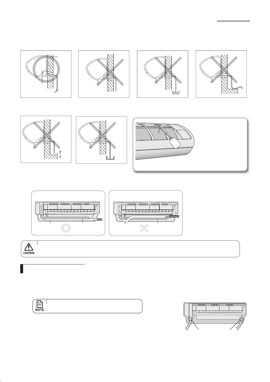
Installing and connecting the drain hose of the indoor unit
The drain hose must NOT
slant upwards.
The end of the drain hose
must NOT be placed under
water.
Keep a clearance of at least
5cm between the end of the
drain hose and the ground.
When installing the drain hose for the indoor unit, check if condensation draining is adequate.
When passing the drain hose through the 65 mm hole drilled in the wall, check the followings:
Drain hose installation
1. If necessary, connect the 2 meter extension drain hose to the drain hose.
2. If you use the extension drain hose, insulate the inside of the extension drain hose with a shield.
3. Fit the drain hose into 1 of 2 drain hose holes, then x the end of the drain hose tightly with a clamp.
4. When extending the Drain Hose, hold the end of Drain Hose and Extended Hose,
rotate and insert the drain hose into Extended hose for
40~45 mm. Make sure the
two hoses are rmly connected, there is no water leakage.
5. Connect the Drain Hose after using Foam Insulation to wrap the Extended Hose. Then, Use vinyl tape to wrap the
each side of connection by 20 mm .
•Ifyoudonotusetheotherdrainhosehole,
block it with a rubber stopper.
Drain hose hole
Wall
Indoor unit
Drain hose
The drain hose must not
be bent.
5cm
less
Do not place the end of the
drain hose in a hollow.
Ditch
After completing the
installation of the drain
hose, pour water into
the drain pan to check
whether the hose is well
drained.
•
Don’t tie drain hose to the assembly pipe which may lead to water leakage.
•Ifthediameteroftheconnectionhoseissmallerthantheproduct'sdrainhose,waterleakagemayoccur.
2) Incorrect connection
Pipe
Drain hose
1) Correct connection
Pipe
Drain hose
English-46
AR5000 ED CO_IB&IM_DB68-05069A_EN.indd 46 2015/3/20 16:15:04
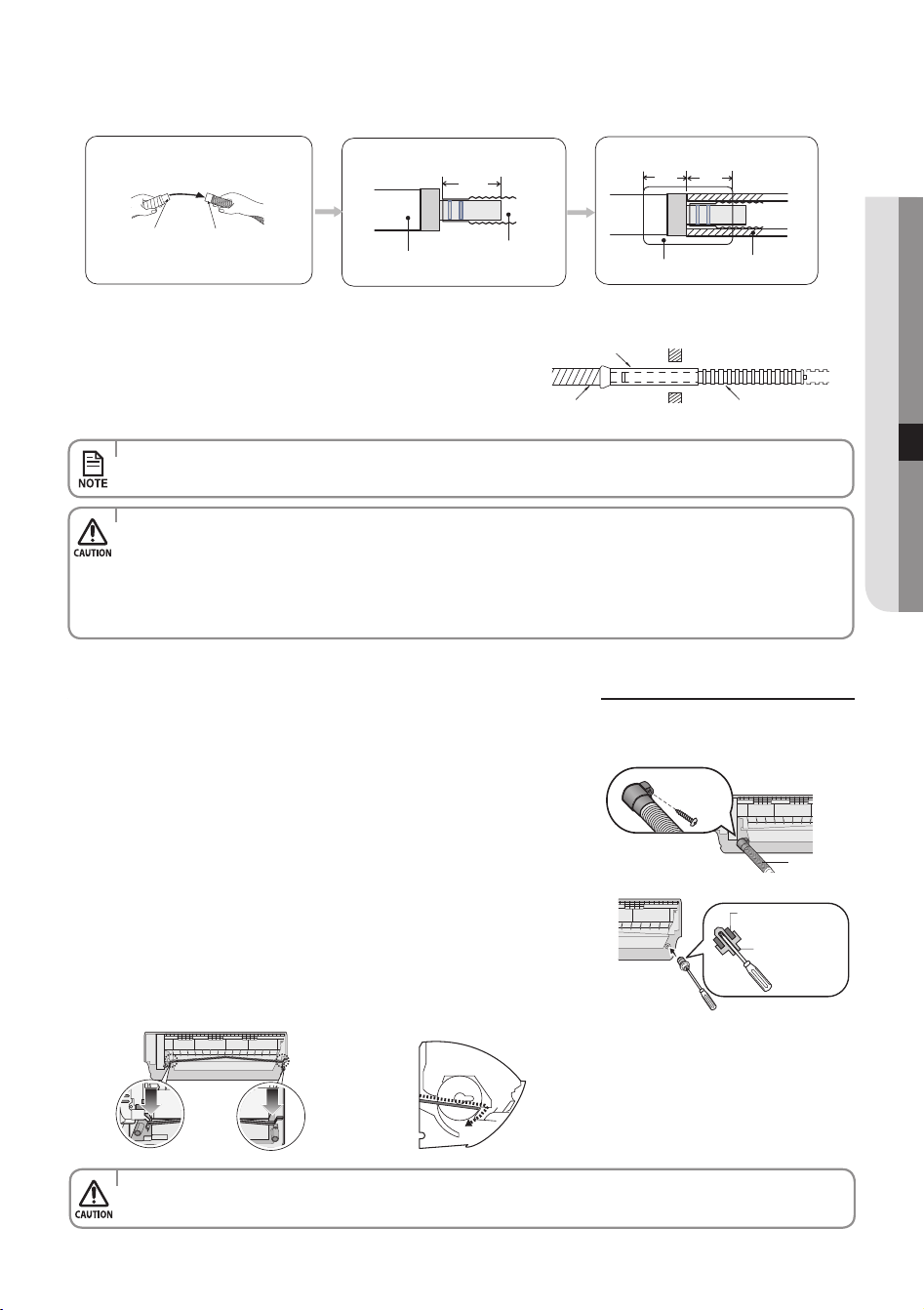
Drain hose
Extension
drain hose
Drain hose
Extension
drain hose
40~45 mm
Foam Insulation
20 mm
or more
20 mm
or more
Vinyl Tape
Changing direction of the drain hose
•Thehosewillbexedpermanentlyintopositionafternishingtheinstallationandthegasleaktest;
refer to page 51 for further details.
•Makesuretheinstalleddirectionofthedrainhoseiscorrect.
Inadequate installation may cause condensate water leakage.
•Ifthedrainhoseisroutedinsidetheroom,insulatethehosesothatdrippingcondensationdoesnotdamagethe
furniture or oors.
•DONOTWALLUPTHEDRAINHOSECONNECTION!
Drain hose connection must be easy accessible and serviceable.
•Makesuretheindoorunitisinuprightpositionwhenyoupourwatertocheckforleakage.
Make sure that the water does not overow onto the electrical part.
Change the direction only when it is necessary.
1. Detach the rubber cap with the pliers.
2. Detach the drain hose by pulling it and turning to the left.
3. Insert the drain hose by xing it with the screw into the groove of the drain
hose and the outlet of the drain pan.
4. Attach the rubber cap with a screwdriver by turning it to the right until it
xes to the end of the groove.
5. Check for leakage on both side of the drain outlet.
Drain hose
Screw hole
Screw
Rubber cap
Drain pan outlet
Pour the water in direction of arrow.
Direction of the drained water
6. Pass the drain hose under the refrigerant pipe, keeping the drain hose tight.
7. Pass the drain hose through the hole in the wall. Check if it slants
downwards as seen in the picture.
8. Using natural drainage method, check the drainage is normal.
Shield
Drain hose Extension drain hose
English-47
InSTaLLaTIOn07
AR5000 ED CO_IB&IM_DB68-05069A_EN.indd 47 2015/3/20 16:15:04
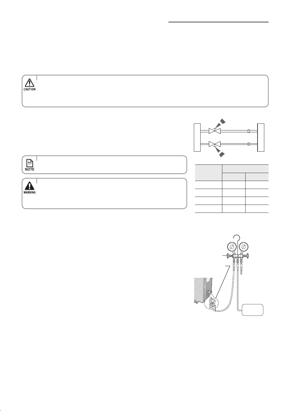
•Wheninstalling,makesurethereisnoleakage.Whenrecoveringtherefrigerant,groundthecompressorrst
before removing the connection pipe. If the refrigerant pipe is not properly connected and the compressor works
with the service valve open, the pipe inhales the air and it makes the pressure inside of the refrigerant cycle
abnormally high. It may cause explosion and injury.
Evacuating the connected pipes
1. Connect each assembly pipe to the appropriate valve on the outdoor unit
and tighten the are nut.
2. Tighten the are nut rst with your hands, and then with a torque wrench,
applying the following torque.
Outdoor unit Indoor unit
Gas pipe side
Liquid pipe side
•Excessivetorquecanbecauseofgasleakage.
•Maketheelectricalconnectionandleavethesysteminto“standby
mode”. Do not turn on the system!
This is necessary for better vacuum operation (full OPEN position of
Electronic Expansion Valve - EEV -).
3. Connect the charging hose of the low-pressure side of manifold gauge to a
gas service port as seen in the picture.
4. Open the valve of the low pressure side of manifold gauge counterclockwise.
5. Evacuate the air in the connected pipes using the vacuum pump for about
15 minutes.
Make sure that pressure gauge shows -0.1MPa(-76cmHg) after about
10 minutes.
This procedure is very important to avoid a gas leak.
Close the valve of the low pressure side of manifold gauge clockwise.
Turn o the vacuum pump.
Check for 2 minutes if there is any pressure change.
Remove the hose of the low pressure side of manifold gauge.
6. Set a valve cork of liquid and gas service port to the open position.
Vacuum
Pump
Manifold gauge
Valve
Gas service port
<Low pressure>
Liquid service port
<High pressure>
(Backward flowing
prevention)
Outer
Diameter
Torque
N•mkgf•cm
ø6.35 mm
14~18 140~180
ø9.52 mm
34~42 350~430
ø12.70 mm
49~61 500~620
ø15.88 mm
68~82 690~830
The outdoor unit is loaded with sucient R-410A refrigerant. Do not vent R-410A into atmosphere: it is a uorinated
greenhouse gas, covered by Kyoto Protocol, with a Global Warming Potential (GWP) = 2088.
You should evacuate the air in the indoor unit and in the pipe. If air remains in the refrigerant pipes, it aects the compressor.
It may cause reduction of cooling capacity and malfunction. Use Vacuum Pump as seen in the picture.
English-48
AR5000 ED CO_IB&IM_DB68-05069A_EN.indd 48 2015/3/20 16:15:04
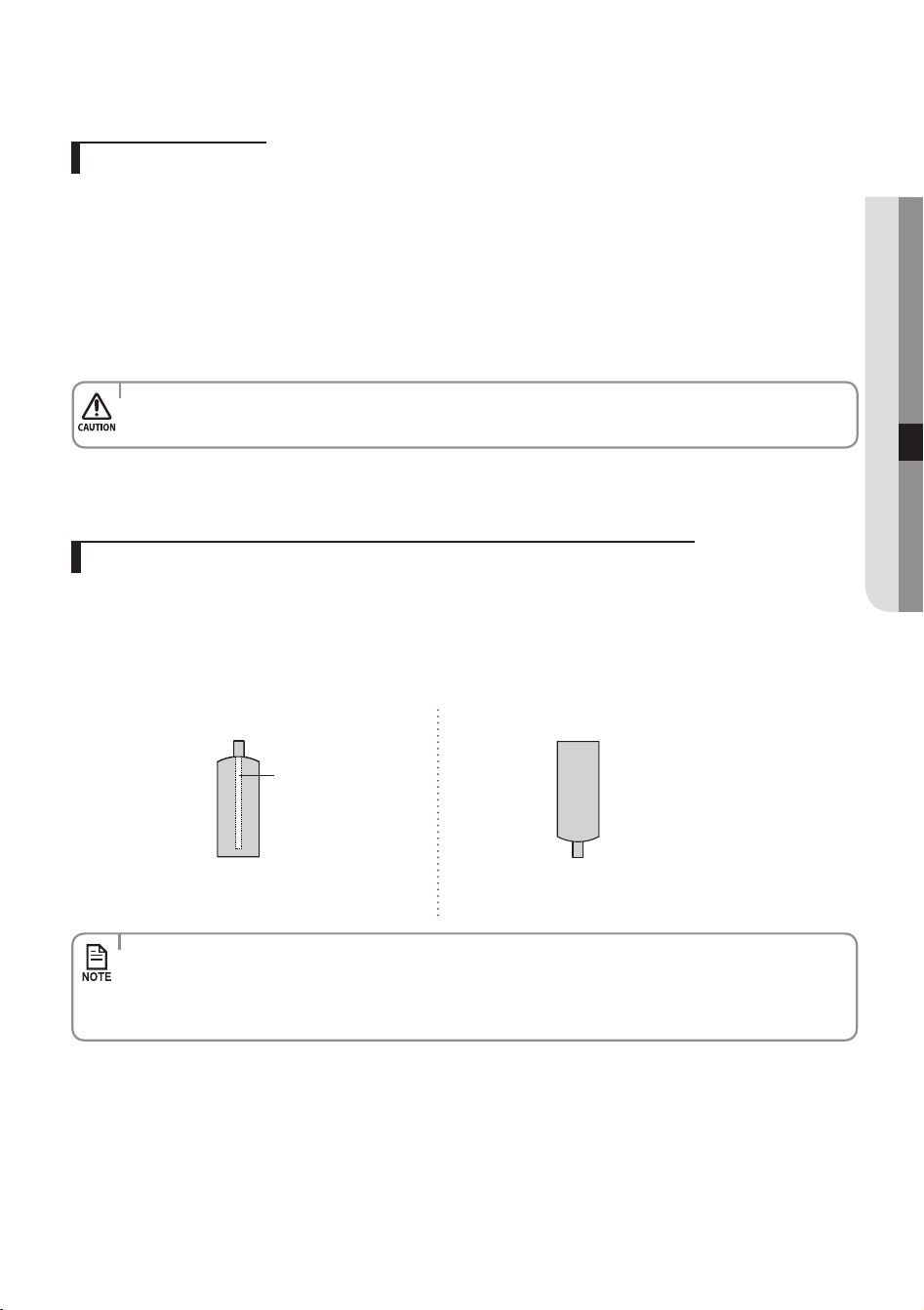
•TheremainingairintheRefrigerationcycle,whichcontainsmoisture,maycausemalfunctiononthecompressor.
•Alwayscontacttheservicecenteroraprofessionalinstallationagencyforproductinstallation.
Adding Refrigerant
Add refrigerant charge according to table below:
If you use a pipe longer than 7.5m,
‘15’ g of refrigerant R-410A must be added for each extra meter.
If you use a pipe shorter than 7.5m,
The evacuate time is normal.
Refer to the Service Manual for further details.
R-410A is a mixed type of refrigerant. It is necessary for recharging under conditions of liquid. When recharging refrigerant from
the refrigerant cylinder to the equipment, follow the instructions below.
1. Before recharging, check whether the cylinder has a siphon or not.
There are two ways to recharge the refrigerant.
Charging the refrigerant under conditions of liquid by using a liquid pipe
Cylinder with siphon
Siphon
f
Charge the refrigerant standing the
cylinder upright.
Cylinder without siphon
f
Charge the refrigerant turning the cylinder
upside down.
•IfR-410Arefrigerantischargedwithgas,thecompositionofthechargedrefrigerantchangesandthe
characteristics of the equipment vary.
•Duringthemeasuringoperationofrefrigerantquantityaddeduseelectronicscales.
If cylinder doesn’t have syphon, upset it.
English-49
InSTaLLaTIOn07
AR5000 ED CO_IB&IM_DB68-05069A_EN.indd 49 2015/3/20 16:15:04
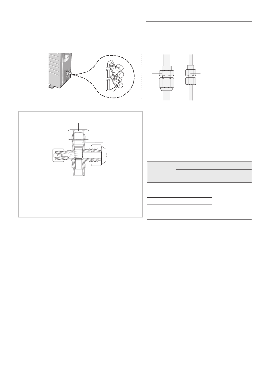
Performing the gas leak tests
C
D
A
B
Make sure to check for gas leaks before completing the installation process (connecting the assembly pipe and hose between
indoor unit and outdoor unit, insulating the cables, hose and pipe, and xing the indoor unit to the installation plate).
To check for gas leaks on the outdoor unit,
Check the valve A and B using a leak detector.
To check for gas leaks on the indoor unit,
Check the are nut C and D using a leak detector.
Test part for outdoor unit
Tightening torque for body cap
(Refer to the table)
Charging
core
Spindle
R-22: Diameter of the screw - 7/16-20UNF
R-410A: Diameter of the screw - 1/2-20UNF
Tightening torque for charging port cap
(Refer to the table)
Test part for indoor unit
Before inspecting the leakage, use a torque wrench
to close the cap for the service valve. (Comply with a
tightening torque for each size of the diameter,and
tighten the cap rmly to prevent any leakage.).
To check for any possible leakage, insert inert gas into
the pipes connected to indoor/outdoor units and
check the connection part of the indoor/outdoor units
with soap lather or liquid for leakage test.
Outer
Diameter
(mm)
Tightening torque
Body cap (N•m)
Charging port cap
(N•m)
ø 6.35
20 ~ 25
10 ~ 12
ø 9.52
20 ~ 25
ø12.70
25 ~ 30
ø15.88
30 ~ 35
ø19.05
35 ~ 40
( 1 N•m = 10 kgf•cm )
Leak test with nitrogen (before opening valves)
In order to detect basic refrigerant leaks, before recreating the vacuum and recirculating the R-410A, it’s responsible of
installer to pressurize the whole system with nitrogen (using a cylinder with pressure reducer) at a pressure above 40 bar
(gauge).
Leak test with R-410A (after opening valves)
Before opening valves, discharge all the nitrogen from the system and create vacuum according to page 48~49.
After opening valves, check leaks using a leak detector for refrigerant.
Pump down (before disconnecting the refrigerant connections for unit repair, removal or disposal)
Pump-down is an operation intended to collect all the system refrigerant in the outdoor unit.
This operation must be carried out before disconnecting the refrigerant tubing in order to avoid refrigerant loss to the
atmosphere.
Shut o the liquid valve with the Allen wrench.
Turn the system on in cooling with fan operating at high velocity.
( Compressor will immediately start, provided 3 minutes have elapsed since the last stop).
After 2 minutes of operation, shut the suction valve with the same wrench.
Turn the system o and switch mains supply o.
Disconnect tubing. After disconnection, protect valves and tubing ends from dust.
Compressor damage may occur if run at a negative suction pressure.
English-50
AR5000 ED CO_IB&IM_DB68-05069A_EN.indd 50 2015/3/20 16:15:04
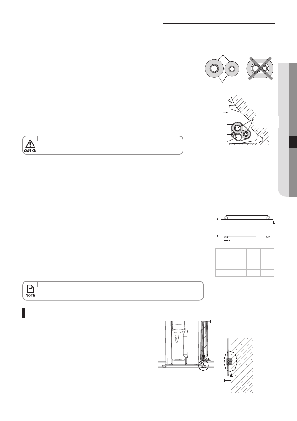
Model X Y
09/12
507 292
18
602 310
24
660 340
English-51
InSTaLLaTIOn07
Fixing the indoor unit in place
Insulation
Pipes
'X' mm
Rubber leg
'Y'
Perform the following work on the area where gas leak test was done priory.
After checking for gas leaks in the system, insulate the pipe, hose and cables.
Then place the indoor unit on the installation plate.
1. To minimise condensation problems, wrap foam insulation (as shown in the
gure) on a part without insulation on the end of the pipes.
2. Wind the pipe, assembly cable and drain hose with vinyl tape.
3. Place the bundle (the pipe, assembly cable and drain hose) in the lower part
of the indoor unit carefully so it does not project from the rear of the indoor
unit.
4. Hook the indoor unit to the installation plate and move the unit to the right
and left until it is securely in place.
Install the outdoor unit in level on a stable base to help avoid the generation of noise and
vibration, especially when installing the unit close to a neighbor.
If you install the outdoor unit in a place exposed to strong winds or at a height, x it to an
appropriate support (wall or ground).
1. Place the outdoor unit as indicated on the top of the unit to let the discharged air out
properly.
2. Fix the outdoor unit in level to an appropriate support using anchor bolts.
3. If the outdoor unit is exposed to strong winds, install shield plates around the
outdoor unit so that the fan can operate correctly.
5. Wrap the rest of the pipe with vinyl tape.
6. Attach the pipe to the wall using clamps (optional).
Installation
plate
Connecting wires
Connecting
pipes
Vinyl tape
Drain hose
•Makesurepipedoesnotmovewhenyouinstalltheindooruniton
an installation plate.
Fixing the outdoor unit in place
•Ensurethewallwillbeabletosuspendtheweightofrackand
outdoorunit;
•Installtherackclosetothecolumnasmuchaspossible;
•Installpropergrommetinordertohelpreducenoiseandresidual
vibration transferred by outdoor unit towards wall.
Outdoor unit installed on the wall by rack
Soft rubber designed to cut off
vibration from rack to wall.
(not supplied with product)
Designed to cut off residual vibration
from outdoor unit to rack.
(not supplied with product)
•Securetherubberlegtohelppreventthegenerationofnoiseandvibration.
AR5000 ED CO_IB&IM_DB68-05069A_EN.indd 51 2015/3/20 16:15:05
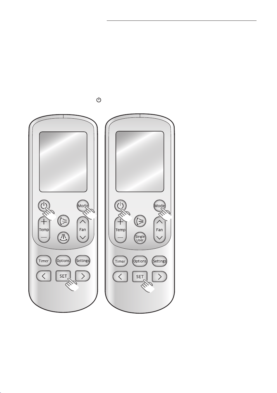
English-52
Smart Install mode
This model supports Smart Install mode which checks installation status to nd out if there is any problems with any of the
functions. Execute Smart Install mode after installation.
1. Check the installation status of the air conditioner.
1) Check the power supply, service valve (if it's open), power cable of the indoor and outdoor unit and amount of
additional refrigerant required for pipe extension.
2) Status of the indicator after supplying the power : Standby status
2. When the air conditioner is in standby status, use the remote controller to start the Smart Install mode.
1) Press the Set, mode and Power
button simultaneously for 4 seconds.
Remote controller may be dierent (image/functions) depending on the model.
AR5000 ED CO_IB&IM_DB68-05069A_EN.indd 52 2015/3/20 16:15:06
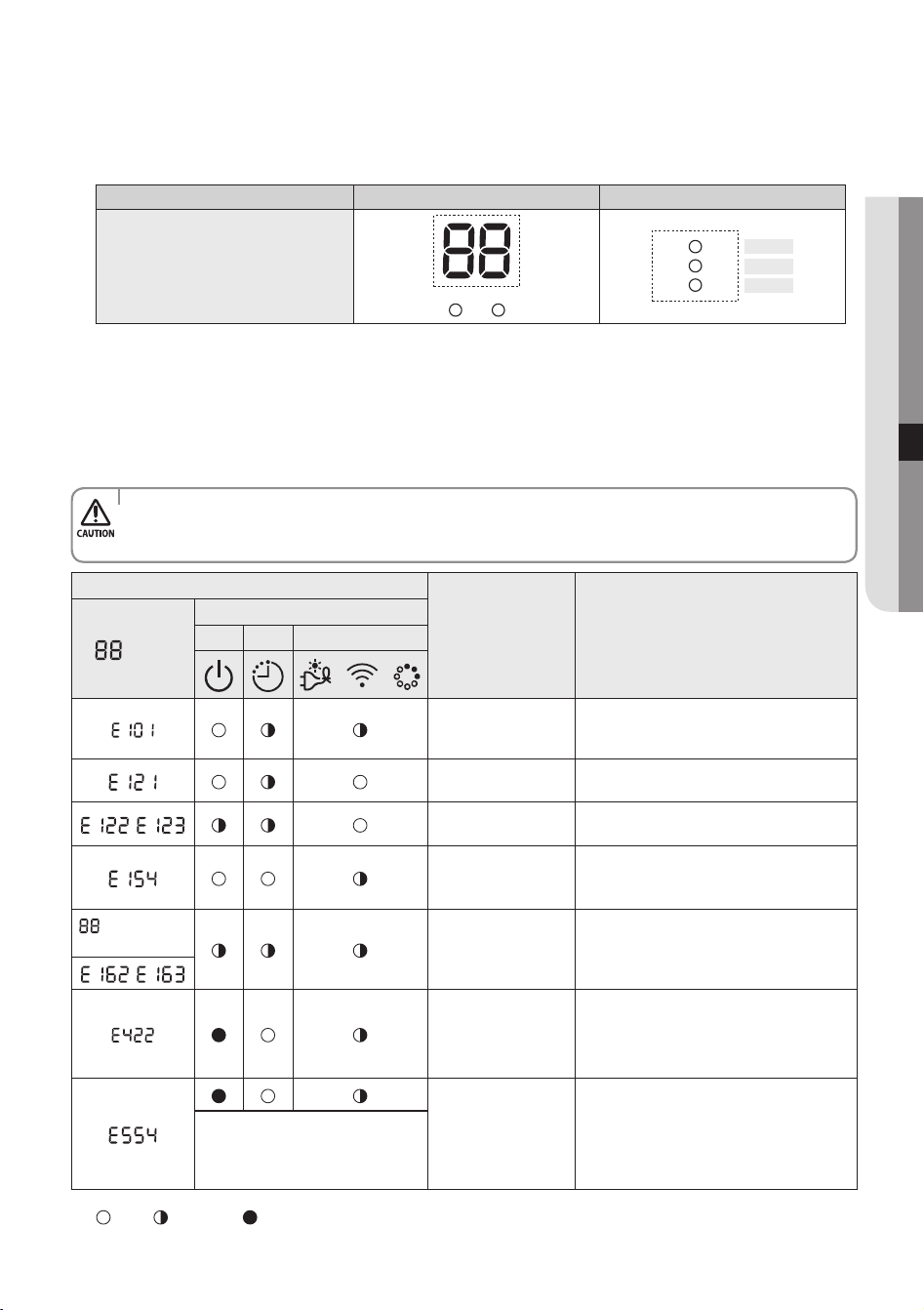
English-53
InSTaLLaTIOn07
2) Smart Install mode in progress
•88 Display : Progress will be diplayed in 0~99.
•LED Display : Indicator on the indoor unit display will blink in sequence and then all indicators will blink. (This will be repeated.)
TYPE 88 Display LED Display
Indoor unit indicator
LED 1
LED 2
LED 3
Display may be dierent depending on the model.
3. Smart Install mode will end.
1) Smart Install mode will take approximately 7~13 minutes. (Actual time may be dierent depending on the model.)
2) When Installation is successful : Smart Install mode will end with ringing sound and the air conditioner will be in standby status.
(Error message will not be displayed on the indoor unit indicator and the remote controller and buttons on the indoor unit will
work normally.)
3) When installation is not successful : Smart Install mode will end and error message will be displayed on the indoor unit display.
1. Take necessary measures when error occurs.
- refer to the service manual for necessary measures for each error that occurs.
2. Use the product after taking care of the error that occurs.
Error indicator
Error measures to take by an installer
Display
LED Display
LED 1 LED 2 LED 3
/ /
Commnuication Error
between Indoor and
outdoor unit
1. Check the connection wire between indoor and
outdoor unit. (whether the power cable and
commnunication cable is crossed or not)
Error on indoor
temperature sensor
1. Check the connection of the connector
,
Error on indoor heat
exchanger
1. Check the connection of the connector
Error on indoor fan motor
1. Check the connection of the connector
2. Remove foreign substance (Check for the cause
that restrains motor)
display and all
LED blinks
EEPROM/Option error
1. Re-set options
,
Refrigerant ow blocking
Error
1. Check if the service valve is completely open.
2. Check if there’s any blockage in the refrigerant
pipe which connects indoor and outdoor unit.
3. Check for refrigerant leak.
Lack of Refrigerant
(For Inverter model only)
1. Check if sucient amount of additional
refrigerant was charged for the pipe length that
exceeds 7.5m.
2. Check for refrigerant leak between valve and
pipe connection.
Above LED pattern is displayed when
there’s error is occurred on outdoor unit.
Check the LED display on outdoor unit
for the details.
: O / : Blinking / : On
AR5000 ED CO_IB&IM_DB68-05069A_EN.indd 53 2015/3/20 16:15:07
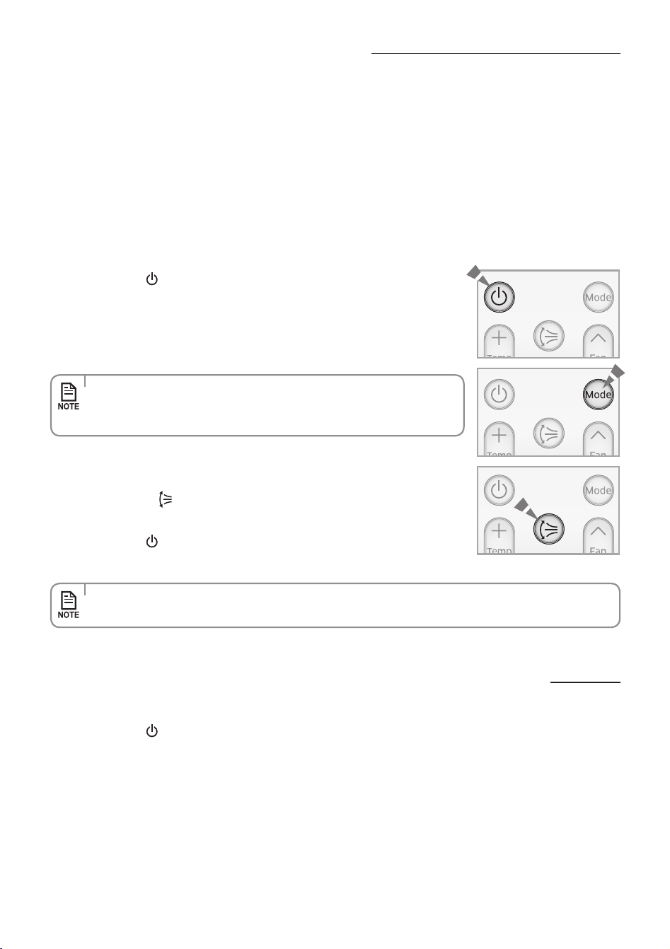
English-54
Final check and trial operation
To complete the installation, perform the following checks and tests to
ensure that the air conditioner operates correctly.
Check the followings:
•Strengthoftheinstallationsite
•Tightnessofpipeconnectiontodetectgasleak
•Electricwiringconnection
•Heat-resistantinsulationofthepipe
•Drainage
•Groundingconductorconnection
•Correctoperation(followthestepsbelow)
1. Press the Power
button and check the following:
The indicator on the indoor unit lights up.
The airow blade opens and the fan gears up for operation.
3. Press the Air swing
button and check the following:
The airow blades work properly.
4. Press the Power
button to stop the operation.
2. Press the Mode button to select Cool mode.
In Cool mode, use Temp + or – button and set the temperature at 16°C.
Cooling mode (indoor unit check) Inlet air temp. - Outlet air temp:
From 10°C to 12°C (indicative delta T)
•Approximately3~5minuteslater,outdoorunitwillstarttooperateandthe
Cool air will blow out.
•After12minutesofstationaryconditionchecktheindoorunitairtreatment.
•Whenyoucompletetheinstallationsuccessfully,handoverthismanualtotheuserforstorageinahandyandsafe
place.
Pump down procedure (when removing the product)
1. Press the Power button on the indoor unit for 5 seconds. Beep will sound immediately to let you know that the
product is ready for pump down procedure. Please let the compressor run for more than 5 minutes.
2 . Release the valve caps on High and Low pressure side.
3 . Use L wrench to close the valve on the high pressure side.
4 . After approximately 2 minutes, close the valve on the low pressure side.
5 . Stop operation of the air conditioner by pressing the power button on the indoor unit or remote controller.
6 . Disconnect the pipes.
AR5000 ED CO_IB&IM_DB68-05069A_EN.indd 54 2015/3/20 16:15:07
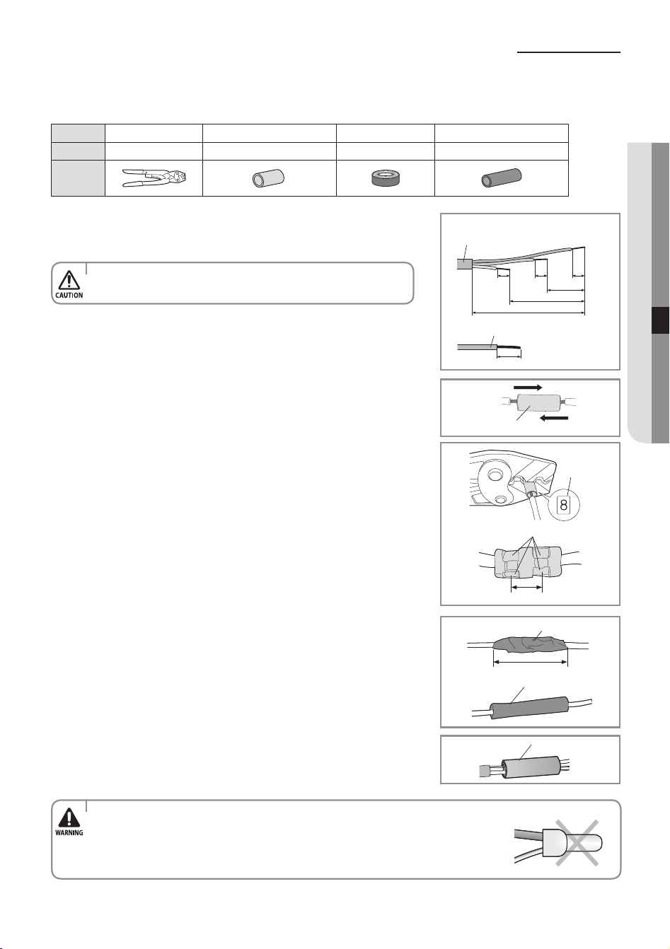
English-55
InSTaLLaTIOn07
how to connect your extended power cables
1. As shown in the gure, peel o the shields from the rubber/wire
of the power cable.
- Peel o 20 mm of the wire shields of the tube installed already.
2. Insert both sides of core wire of the power cable into the connection sleeve.
3. Using a compressor, compress the two points and ip it over
and compress another two points in the same location.
- The compression dimension should be 8.0.
- After compressing it, pull both sides of the wire to
make sure it is rmly pressed.
4. Wrap it with the insulation tape twice and position your
contraction tube in the middle of the insulation tape.
5. Apply heat to the contraction tube to contract it.
6. After tube contraction work is completed, wrap it with the
insulation tape to nish.
Tools Crimping pliers
Connection sleeve (mm)
Insulation tape
Contraction tube (mm)
Spec
MH-14 20xØ7.0(HxOD) Width 18 mm 50xØ8.0(LxOD)
Shape
40 mm
Insulation tape
Contraction tube
(Unit: mm)
120
60
202020
180
Power cable (provided by us)
20
Wire tube power cable
Connection sleeve
Comp. dim.
Compress it 4 times
5 mm
Insulation tape
•Afterpeelingothetubewire,youmustinsertacontractiontube.
•Incaseofextendingtheelectricwire,pleaseDONOTusearound-shapedpressingsocket.
- Incomplete wire connections can cause electric shock or a re.
Items to prepare
(compressor and insulation tape should be prepared by an installation technician.)
AR5000 ED CO_IB&IM_DB68-05069A_EN.indd 55 2015/3/20 16:15:07
QUESTIONS OR COMMENTS?
COUNTRY CALL OR VISIT US ONLINE AT
MEXICO 01-800-SAMSUNG(726-7864) www.samsung.com/mx/support
BRAZIL
0800-124-421 (Demais cidades e regiões)
4004-0000 (Capitais e grandes centros)
www.samsung.com/br/support
COSTA RICA
0-800-507-7267
00-800-1-SAMSUNG (726-7864)
www.samsung.com/latin/support (Spanish)
www.samsung.com/latin_en/support (English)
DOMINICA
1-800-751-2676
www.samsung.com/latin/support (Spanish)
www.samsung.com/latin_en/support (English)
ECUADOR
1-800-10-72670
1-800-SAMSUNG (72-6786)
www.samsung.com/latin/support (Spanish)
www.samsung.com/latin_en/support (English)
EL SALVADOR 800-6225
www.samsung.com/latin/support (Spanish)
www.samsung.com/latin_en/support (English)
GUATEMALA
1-800-299-0013
1-800-299-0033
www.samsung.com/latin/support (Spanish)
www.samsung.com/latin_en/support (English)
HONDURAS
800-27919267
800-2791-9111
www.samsung.com/latin/support (Spanish)
www.samsung.com/latin_en/support (English)
JAMAICA
1-800-234-7267
1-800-SAMSUNG (726-7864)
www.samsung.com/latin_en/support (English)
NICARAGUA 001-800-5077267
www.samsung.com/latin/support (Spanish)
www.samsung.com/latin_en/support (English)
PANAMA
800-7267
800-0101
www.samsung.com/latin/support (Spanish)
www.samsung.com/latin_en/support (English)
PUERTO RICO 1-800-682-3180
www.samsung.com/latin/support (Spanish)
www.samsung.com/latin_en/support (English)
TRINIDAD
& TOBAGO
1-800-SAMSUNG(726-7864)
www.samsung.com/latin/support (Spanish)
www.samsung.com/latin_en/support (English)
Venezuela 0-800-SAMSUNG (726-7864) www.samsung.com/ve/support
COLOMBIA
Bogotá 600 12 72
Gratis desde cualquier parte del país 01 8000 112 112 ó
desde su celular #SAM(726)
www.samsung.com/co/support
CHILE
800-SAMSUNG(726-7864)
[HHP] 02-24828200
www.samsung.com/cl/support
BOLIVIA
800-10-7260
[HHP] 4828210
www.samsung.com/cl/support
PERU 0-800-777-08 www.samsung.com/pe/support
ARGENTINE 0800-333-3733 www.samsung.com/ar/support
URUGUAY 000-405-437-33
www.samsung.com/latin/support (Spanish)
www.samsung.com/latin_en/support (English)
PARAGUAY 009-800-542-0001
www.samsung.com/latin/support (Spanish)
www.samsung.com/latin_en/support (English)
DB68-05069A-02
AR5000 ED CO_IB&IM_DB68-05069A_EN.indd 56 2015/3/20 16:15:08
ARJV Series
Air Conditioner
user & installation manual
imagine the possibilities
Thank you for purchasing this Samsung product.
This manual is made with 100% recycled paper.
AR5000 ED CO_IB&IM_DB68-05069A_EN.indd 57 2015/3/20 16:15:08