Loading ...
Loading ...
Loading ...
5
FINAL ASSEMBLY
1. Protect motor, bulb sockets and wiring from construction
dust, drywall spray, paint, etc. by using the plaster shield. Cut
it from the carton and follow directions printed on it. (Fig. 7)
2. Finish all ceiling work as necessary.
3. Remove plaster shield and check if bottom of housing is
flush with finished ceiling. If not, loosen vertical adjusting
screws, reposition housing, and retighten screws.
4. Attach grille by hooking springs onto clips on side of
housing. (Fig. 8)
5. Install BR40 or R40-size 250W infrared bulb(s). Center
grille around bulb(s).
ENSAMBLADO FINAL
1. Proteja el motor, enchufe de la bombilla y cableado contra el
polvo de la construcción, rocíos de yeso, pintura, etc., usando
el escudo de yeso. Córtelo de la caja de cartón y siga las ins-
trucciones que aparecen impresas en la misma. (Fig. 7)
2. Termine el trabajo de cielo raso ségun se necesite.
3. Quite el escudo de yeso y verifique si la parte inferior de la caja
está a nivel con el cielo raso terminado. De lo contrario, afloje
los tornillos de ajuste vertical, cambie la posición de la caja y
vuelva a apretar los tornillos.
4. Fije la rejilla enganchando los resortes a los sujetadores al
costado de la caja. (Fig. 8)
5. Instale bombilla(s) infrarrojas 250W de tamaño BR40 o R40.
Centre la rejilla alrededor de la(s) bombilla(s).
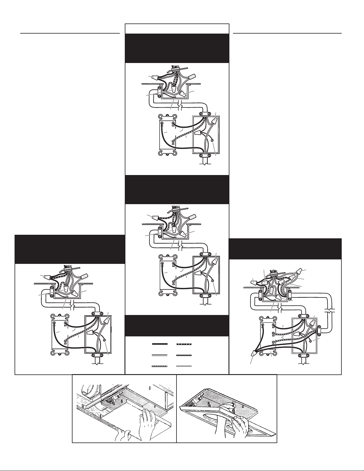
FIG. 6 (CONT')
MODEL / MODELO 164
Vent & Heat operate together -
Light separately
El Ventilador y Calentador funcionan a la vez
-La Luz por separado
MODEL / MODELO 164
Lamps operate together -
Vent separately
Las Lamparas funcionan a la vez -
El ventilador por separado
120 VAC LINE IN
LINEA DE ENTRADA 120 VCA
GROUND
TIERRA
LIGHT
LUZ
DUAL CONTROL
CONTROLE DE 2 FUNCCIONES
3 WHITE / GRAY WIRES
3 ALAMBRES
BLANCO / GRIS
VENT & HEAT
VENTILADOR y
CALEFACCION
BLACK to BLACK,
& YELLOW
NEGRO a
NEGRO
y AMARILLO
RED to RED
& BLUE
ROJO a ROJO
y AZUL
GROUND / TIERRA
RED
ROJO
WHITE to
WHITE
BLANCO a
BLANCO
BLACK
NEGRO
120 VAC LINE IN
LINEA DE ENTRADA 120 VCA
GROUND
TIERRA
VENT
VENTILADOR
DUAL CONTROL
CONTROLE DE 2 FUNCCIONES
3 WHITE / GRAY WIRES
3 ALAMBRES
BLANCO / GRIS
HEAT & LIGHT
CALEFACCION
y LUZ
BLACK to
BLUE
NEGRO a
AZUL
RED to RED,
BLACK &
YELLOW
ROJO a ROJO,
NEGRO y
AMARILLO
GROUND / TIERRA
RED
ROJO
WHITE to
WHITE
BLANCO a
BLANCO
BLACK
NEGRO
WIRE COLOR LEGEND
For wiring diagrams
on pages 2 & 3
WHITE
BLANCO
RED
ROJO
BLACK
NEGRO
BLUE
AZUL
GROUND
TIERRA
YELLOW
AMARILLO
120 VAC LINE IN
LINEA DE ENTRADA 120 VCA
GROUND
TIERRA
LIGHT
& VENT
LUZ y
EXTRACCION
DUAL CONTROL
CONTROLE DE 2 FUNCCIONES
3 WHITE / GRAY WIRES
3 ALAMBRES
BLANCO / GRIS
HEAT
CALEFACCION
BLACK to
BLACK, & BLUE
NEGRO a
NEGRO y AZUL
RED to RED
& YELLOW
ROJO a ROJO
y AMARILLO
GROUND / TIERRA
RED
ROJO
WHITE to
WHITE
BLANCO a
BLANCO
BLACK
NEGRO
MODEL / MODELO 164
Light & Vent operate together -
Heat separately
La luz y el ventilador funcionan a la vez -Calenta-
dor por separado
HEAT
CALIFACCION
120 VAC LINE IN
LINEA DE ENTRADA 120 VCA
GROUND
TIERRA
3 BLACK WIRES
3 ALAMBRES NEGR OS
3 WHITE WIRES
3 ALAMBRES
BLANCOS
LIGHT
LUZ
BLACK
NEGRO
3-FUNCTION CONTROL
CONTROL DE TRES FUNCCIONES
WHITE to WHITE / GRAY
BLANCO a BLANCO / GRIS
VENT
EXTRACCION
BLACK to BLACK
NEGRO a NEGRO
BLACK to YELLOW
NEGRO a AMAR ILLO
RED to RED
ROJ O a ROJO
RED / ROJO
GROUND / TIERRA
WHITE to WHITE
BLANCO a BLANCO
RED to BLUE
ROJ O a AZUL
MODEL / MODELO 164
Light, Vent & Heat operate separately. La luz,
ventilador y calentador funcionan por separado
FIG. 7
FIG. 8
Loading ...
Loading ...
Loading ...