Loading ...
Loading ...
Loading ...
GB
26
Installation of indoor unit
Step one: choosing installation location
Recommend the installation location to the client and then confirm it with the client.
Step two: install wall-mounting frame
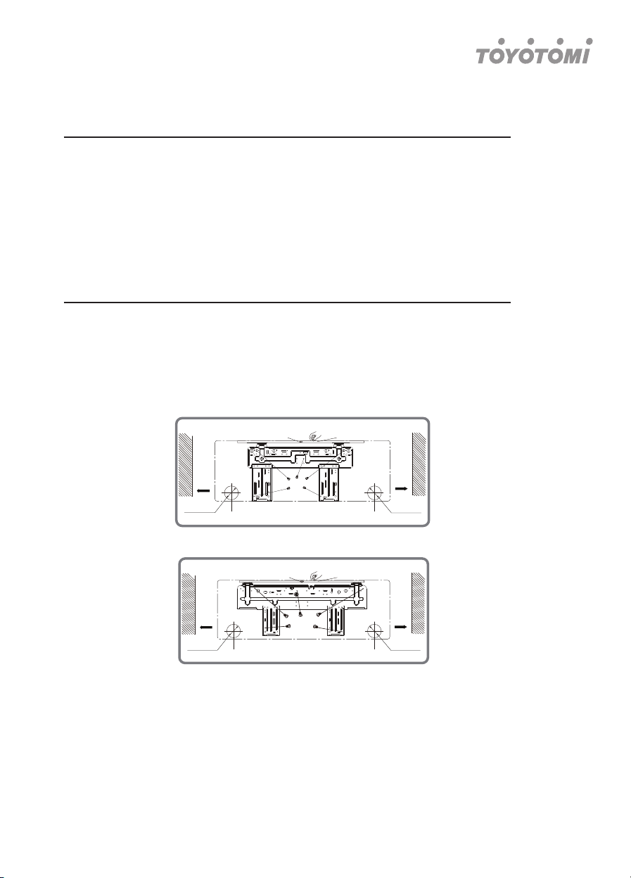
1. Hang the wall-mounting frame on the wall; adjust it in horizontal position with the
level meter and then point out the screw fixing holes on the wall.
2. Drill the screw fixing holes on the wall with impact drill (the specification of drill
head should be the same as the plastic expansion particle) and then fill the
plastic expansion particles in the holes.
3. Fix the wall-mounting frame on the wall with tapping screws (ST4.2X25TA) and
then check if the frame is firmly installed by pulling the frame. lf the plastic
expansion particle is loose, please drill another fixing hole nearby.
Step three: open piping hole
1. Choose the position of piping hole according to the direction of outlet pipe.
The position of piping hole should be a little lower than the wall-mounted frame,
shown as below.
2. Open a piping hole with the diameter of 55 or 70 on the selected outlet pipe position.
ln order to drain smoothly, slant the piping hole on the wall slightly downward to the out
door side with the gradient of 5-10°.
(Rear piping hole)
9K & 12K
17K & 21K
Mark in the middle of it
Mark in the middle of it
Wall
Wall Wall
Space
to the
wall
above
150mm
Space
to the
wall
above
150mm
Space
to the
wall
above
150mm
Space
to the
wall
above
150mm
(Rear piping hole)
Left
ф 55mm
Left
ф 55mm
Right
ф 55mm
Right
ф 55mm
(Rear piping hole)
(Rear piping hole)
Wall
Level meter
Level meter
Loading ...
Loading ...
Loading ...