Owners
Manual
FOR POTABLEWATER
HEATING ONLY
NOT SUITABLEFOR
SPACEHEATING
NOT FOR USE IN
MOBILE HONES
Model No.
153.330401 40 Gal. High Altitude
153.330451 40 Gal.
153.330501 50 Gal. High Altitude
153.330551 50 Gal.
153.330701 75 Gal. High Altitude
153.330751 75 Gal
Caution:
Read and Follow
All Safety Rules and
Operating Instructions
Before First Use of
This Product.
Save this Manual for Future Reference.
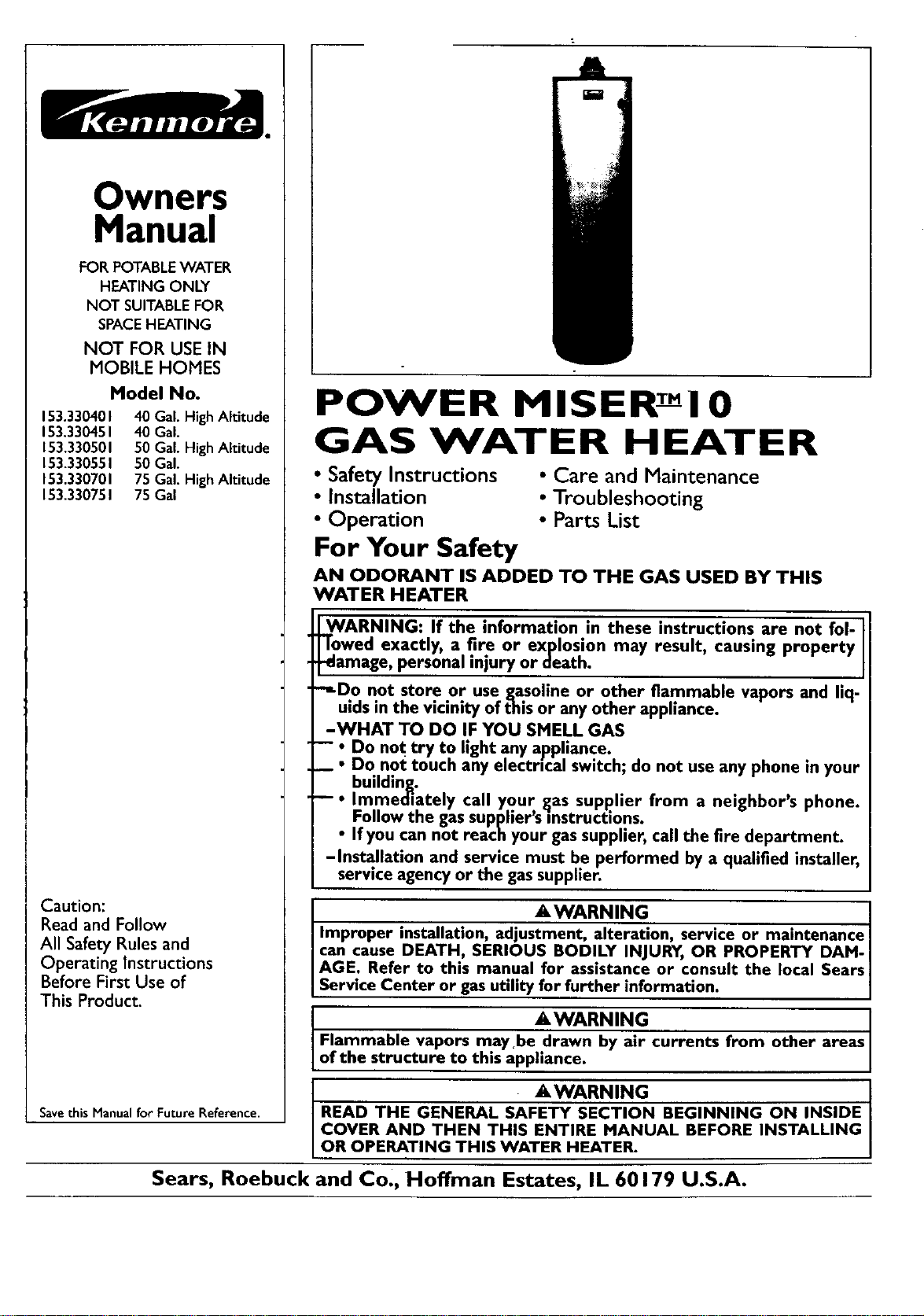
POWER MISER ! O
GAS WATER HEATER
•Safety Instructions • Care and Maintenance
• Installation • Troubleshooting
•Operation • Parts List
For Your Safety
AN ODORANT IS ADDED TO THE GAS USED BY THIS
WATER HEATER
WARNING: If the information in these instructions are not fol-
"lowed exactly, a .fire or explosion may result, causing property
-damage, personal mlury or death.
-,,Do not store or use gas.oline or other flammable vapors and liq-
uids in the vicinity of this or any other appliance.
-WHAT TO DO IF YOU SMELL GAS
-- :Do not try to light any appliance.
Do not touch any electrtcal switch; do not use any phone in your
building.
• Imme_ately call your gas supplier from a neighbor's phone.
Follow the gas supplier's]nstructions. - -
If you can not reach your gas supplier, call the fire department.
-Installation and service must be performed by a qualified installer,
service agency or the gas supplier.
AWARNING ]
•. -
Improper installatmn, adjustment, alteration, service or mamtenancel
can cause DEATH, SERIOUS BODILY INJURY, OR PROPERTY DAM-|
AGE. Refer to th,s manual for assistance or consult the local Sears|
Service Center or gas utility for further information. |
_,WARNING
Flammable vapors maybe drawn by air currents from other areas
of the structure to this appliance•
_,WARNING
READ THE GENERAL SAFETY SECTION BEGINNING ON INSIDE
COVER AND THEN THIS ENTIRE MANUAL BEFORE INSTALLING
OR OPERATING THIS WATER HEATER.
Sears, Roebuck and Co., Hoffman Estates, IL 60179 U.S.A.
Safety Precautions
•_W,.ARNING .
Impro.per installation, adjustment , alteration, service
or maintenance can cause DEATH, SERIOUS BODILY
INJURY,OR PROPERTY DAMAGE. Refer to this manu-
I al for assistance or consult your local Sears Service
[ Center for further information.
AWARNING
WATER HEATERS EQUIPPED FOR ONE TYPE GAS
ONLY: This water heater is equipped for one type gas
only. Check the model rating plate near the gas control
valve for the correct gas. DO NOT USE THIS WATER
HEATER WITH ANY GAS OTHER THAN THE ONE
SHOWN QN THE MODEL RATING PLATE. Failure to
usethe correct gascancauseproblem'swhichcanresultin
DEATH, SERIOUS BODILY INJURY, OR PROPERTY
DAMAGE. If you have any questions or doubts consult
yourgassupplieror localutility.
AWARNING
INSTALLATIONS IN AREAS WHERE FLAMMABLE LIQ-
UIDS (VAPORS) ARE LIKELY TO BE PRESENT OR
STORED (GARAGES, STORAGE, AND UTILITY AREAS,
ETC): Flammable liquids (such as gasoline, solvents,
propane(LP) or butane, etc.), all ofwhichemit flammable
vapors, may be improperly stored or usedin suchareas.
The gaswater heater pilot light or main burner canignite
such vapors. The resulting flashbackand fire can cause
death or serious burns to anyone in the area, as well as
property damage.
If installation in such areas is your onlyoption, then the
installation must be accomplishedin a way that the pilot
flame and main burner flame are elevated from the floor
at least 18 inches.While this may reduce the chancesof
flammable vaporsfrom a floor spillbeingignited,gasoline
and other flammablesubstancesshouldnever bestoredor
used in the same room or area containing a gaswater
heater or other openflame or sparkproducingappliance.
NOTE: Flammable vapors may be drawn by air currents
from other areasofthe structureto the appliance.
AWARNING
If this water heater will be usedin beauty shops,barber
shops,cleaning establishments, or self-servicelaundries
with dry cleaning equipment, it is imperative that the
water heater or water heaters be installed sothat com-
bustion and ventilation air be taken from outside these
areas. Refer to the "Facts to Consider About the
Location" section of this manual and also the latest edi-
tion of the National Fuel Gas Code, ANSI Z223.1, also
referred to as NFPA 54 for specificsprovidedconcerning
air required.
_.WARNING ]
A fire can start if co_Hals suchas clothing,|
cleaningmaterials, or flammable liquidsare placedagainst|
or next to thewater heater. /
_,WARNING
At the time of manufacture this water heater was provid-
edwith acombination temperature-pressures relief valve
certified by a nation.ally, recognized testing laboratory
that maintains penodlc inspectionof production of listed
equipment or materials, as meeting the requirements for
ReliefValvesand Automatic Gas Shutoff Devicesfor Hot
Water Supply Systems, and the latest edition of ANSI
Z21.22 and the code requirements of ASME. If replaced,
the valve must meet the requirements of localcodes,but
not lessthan a combination temperature and pressure
relief valve certified as meeting the requirements for
ReliefValvesand Automatic Gas Shutoff Devicesfor Hot
Water SupplySystems,ANSI Z21.22 by a nationally rec-
ognized testing laboratory that maintains periodic
inspection of production of listed equipment or
materials.
The valve must be marked with a maximum set pressure
not to exceed the marked hydrostaticworking pressure
of the water heater (150 Ibs./sq. in.) and a discharge
capacity not lessthan the water heater input rate as
shown on the model rating plate. (Electric heaters -
watts dividedby 1000x 3415 equal BTU/Hr. rate.)
Your local jurisdictional authority, while mandating the
use of a temperature-prossure relief valve complying
with ANSI Z21.22 and ASME, may require a valve model
different from the one furnishedwith the water heater.
Compliance with suchlocal requirements must be satis-
fied bythe installer or end userof the water heater with
a locally prescribed temperature-pressure relief valve
installedin the designatedopeningin the water heater in
place ofthe factory furnishedvalve.
For safe operation of the water heater, the relief valve
must not b_ _OV---e'a'Trom_-'T_-'ed_g_aT_d_opening or
plugged...........................
The temperature-pressure relief valve must be installed
directly into_he_fieein_f_the-weter heater designatedfor
the relief valve. Positionthe valvedownward and provide
tubing sothat anydischal_e-WHT_it onlywithin 6 inches
above, or at any_dis.tancebe!ow the structural floor. Be
certain that no contact is made with any live electrical
part. The discharge.opening must not be blocked or
reduced in size under any circumstances. Excessive
length,over'30"feet,-or useofmore than four elbowscan
cause restriction and reduce the discharge capacity of
the valve.
No valve or other obstruction is to be placed between
the relief valve and the tank. Do not connect tubing
directly to dischargedrain unlessa6 air gap is provided.
To prevent bodily injury, hazard to life, or property dam-
age, the relief valvemust be allowed to dischargewater
in quantities should circumstances demand• If the dis-
chargepipe isnot connected to a drain or other suitable
means,the water flow may causeproperty damage.
The DischargePipe:
Must not be smaller in size than the outlet pipe size of
the valve, or have any reducing couplings or other
restrictions.
Must not be pluggedor blocked.
Must be of material listedfor hot water distribution.
Must be installedso as to allow complete drainage of
both the temperature-pressure relief valve,and the dis-
chargepipe.
• Must terminate at an adequatedrain.
•Must not have any valve between the relief valve and
tank.
?
Safety Precautions
_,WARNING
A gaswater beater cannot operate properly without the
correct amount of air for combustion. Do not install in a
confined area such a closet, unless you provide air as
shownin the "Facts to Consider About the Location" sec-
tion. Never obstruct the flow of ventilation air. If you have
any doubts or questions at all, call your gas company.
Failure to provide the proper amount of combustion air
can result in afire or explosion and can cause DEATH
SERIOUS BODILY INJURY,OR PROPERTY DAMAGE.
AWARNING
This water heater must not be installed directly on car-
peUng.Carpeting must be protected bya metal or wood
panel beneath the appliance extending beyond the full
width and depth of the appliance by at least 3 inches
(76.2mm) in any direction, or if the appliance isinstalled
in analcove or closet,the entire floor must becoveredb
the panel. Failure to heed this warning may result in i
fire hazard.
A,WARNING
HOTTER WATER CAN SCALD: Water heaters are
intended to produce hot water. Water heated to a tam-
peraturo whichwill satisfyclotheswashing;dishwashing,
and other sanitizing needs can scald and permanently
injure you upon contact. Some people are more likelyto
be permanently injured by hot water than others. These
includethe eldedy, children,the infirm, or physically/men-
tally handicapped.If anyoneusinghot water in yourhome
fits into one of these groupsor if there is a local code or
state law requiring a certain temperature water at the hot
water tap, then you must take specialprecautions.In addi-
tion to usingthe lowest possibletemperature setting that
satisfiesyour hot water needs,a means suchas a mixing
valve, shouldbe usedat the hot water taps usedbythese
people or at the water heater. Mixingvalvesare available
at plumbing supplyor hardware stores. Follow manufac-
turers instructions for installation of the valves. Before
changingthe factory setting on the thermostat, read the
"Temperature Regulation"sectionin this manual.
_,WARNING
Soot build-up indicates a problem that requires correc-
tion beforefurther use.Turn "OFF" gasto water heater
and leave "OFF" until repairs are made, becausefailure
to correct the causeof the sootingcan result in a fire or
explosion causing DEATH, SERIOUS BODILY INJURY,
OR PROPERTY DAMAGE.
AWARNING
VENT DAMPERS - Any vent damper,whether it isoperat.
ed thermally or otherwise must be removed if its use
inhibitsproper draftingof the water heater.
Thermally Operated Vent Dampers: Gas-fired water
heaters having thermal efficiencyin excessof 80% may
produce a relatively low flue gastemperature. Suchtem-
peratures may not be high enoughto properly openther-
mally operated vent dampers.Thiswouldcausespillageof
fluegasesand may causecarbonmonoxide poisoning.
Vent dampers must bear evidenceof certificationas com-
plying with the latest edition of American National
Standard ANSI Z21.68 (ANSI Z21.66 & 67, respectively,
cover electrically and mechanically actuated vent
dampers). Before installationof anyvent damper, consult
your localSears Service Center or the gasutility for fur-
ther information.
_,WARNING
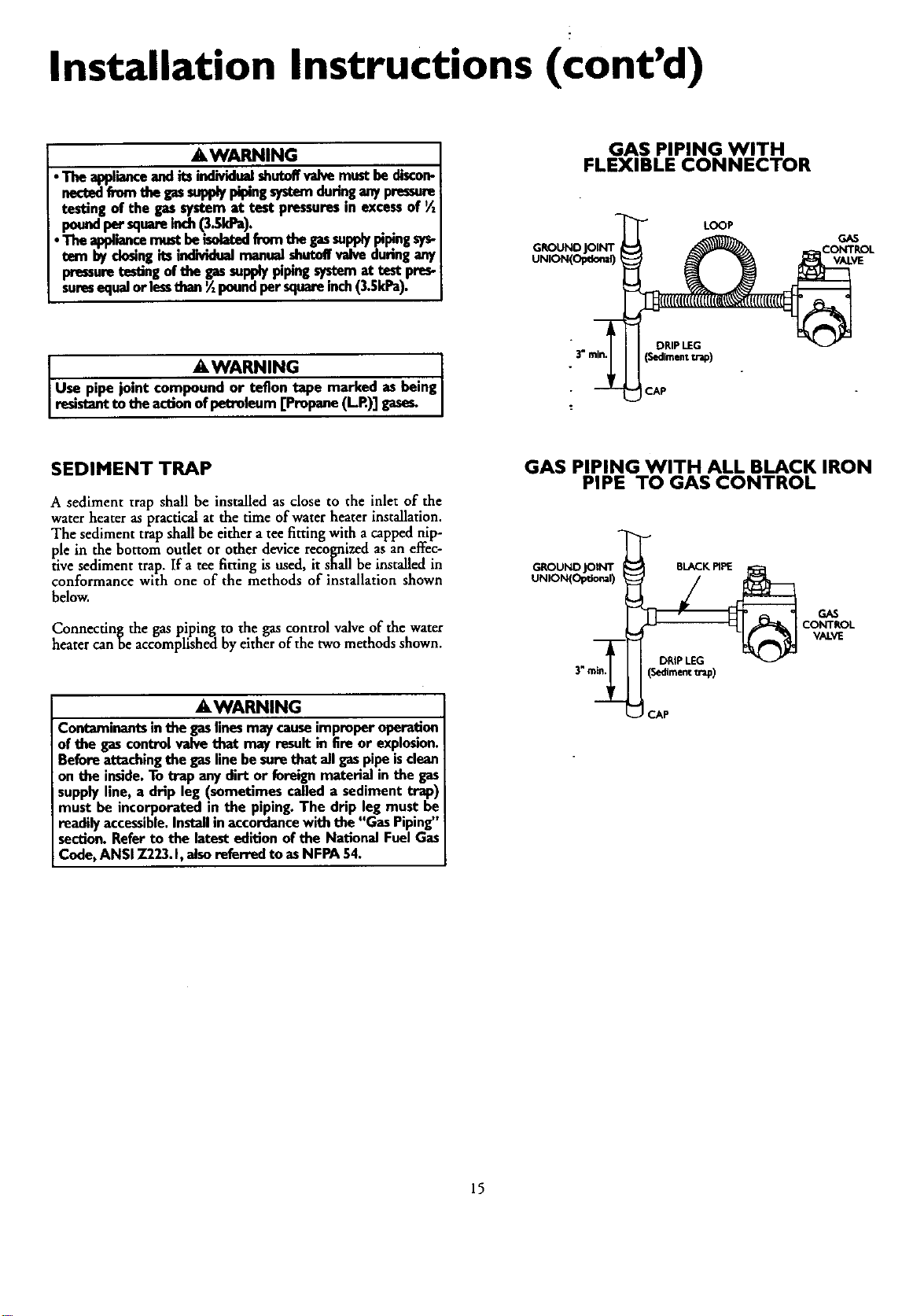
•The appliance and its individualshutoffvalvemustbe dis-
connectedfrom the gassupplypipingsystemduring any
pressure testing of the gassystem at test pressuresin
excessof ½poundper squareinch(3.5kPa).
•The appliance must be isolatedfrom the gassupplypip-
ing system by closingits individualmanual shutoffvalve
during any pressuretestingof the gassupplypipingsys-
tem at test pressuresequal or lessthan Y_pound per
squareinch(3.5kPa).
AWARNING
BEFORE LIGHTING [PROPANE (L.R) GAS WATER
HEATERS]: Propane (L.R) gasis heavier than air. Should
there be a leak in the system,the gaswill settle near the
ground. Basements, crawl spaces, skirted areas under
mobile homes (even when ventilated), closets and areas
below groundlevelwill serve as pocketsfor the accumula-
tion of this gas.Before attempting to light or relight the
water heater's pilot or turning on a nearby electrical light
switch, be absolutelysure there is no accumulated gasin
the ares Search for odor of gasbysniffingat groundlevel
in the vicinity of the appliance. If odor is detected, follow
stepsindicatedat "For Your Safety" on the cover page of
this manualthen leavethe premises.
_,WARNING
Chemical vapor corrosion of the flue and vent system
may occur if air for combustioncontainscertain chemical
vapors.Spraycanpropellants,cleaningsolvents,refrigera-
tor and air conditioner refrigerants, swimming pool
chemicals, calcium and sodium chloride, waxes, bleach,
and processchemicalsare typical compoundswhich are
potentially corrosive.
A, WARNING
iObstructed or deteriorated vent systemsmay present a
serioushealthrisk or asphyxiation.
3
Safety Precautions continued on page 4
Safety Precautions
._,WARNING I
The water heater with draft hood installedmust be prep. [
erly vented to achimney which termm.ates outdoors. I
Never operate the water heater unlessit is vented to the
outdoors and has adequate air supply.to avoid risks of
improper operation,explosionor asphyxiation.
AWARNING
Minimum clearancesbetween the water heater and com-
bustibleconstructionare I" at the sidesand rear, 4" at the
front, and 6" from the vent pipe. Clearance from the top
of the jacket is 18" on most models. Note that a lesser
dimensionmay be allowed on some models. Refer to the
labelonthe water heater adjacentto the gascontrolvalve
for all clearances.
.&WARNING [
Do not usethis applianceif any part of.it hasbeen under I
water. Immediately call a Sears Service Technician to [
inspectthe applianceand to replace the gascontrol or any
part ofthe burner systemwhich hasbeen underwater.
ACAUTION .....
WATER HEATERS EVENTUALLY LEAK: Installation of
the water heater must be accomplished in suchamanner
that ifthe tank or anyconnectionsshouldleak, the flow of
water will not causedamage to the structure. When such
locationscannot be avoided,a suitable drain pan should
be installedunder the water heater, Drain pansare avail-
able at your local Searsstore. Such adrain pan must be
not greater than 1%inchesdeep, havea minimum length
and width of at least 2 Inches greater than the water
heater dimensions and must be piped to an adequate
drain. The pan must not restrict combustion air' flow,
Under no circumstancesisthe manufacturer or Searsto
be held liable for any water damage in connection with
thiswater heater,
_,WARNING
HYDROGEN GAS: Hydrogengascanbeproducedin a hot
water system that hasnot been usedfor along period of
time (generally two weeks or more). Hydrogen gas is
extremely flammable and explosive.To prevent the possi-
bility ofinjury under these conditions,we recommend the
hot water faucet be opened for several minutes at the
kitchen sink before any electrical applianceswhich are
connectedto the hot water systemare used(suchasa dis-
hwasheror washingmachine). If hydrogengasis present,
there will probably he an unusual sound similar to air
escaping through the pipe as the hot water faucet is
opened. There must be no smoking or open flame near
the faucnt at the time it isopen.
a, WARNING
INSULATING JACKETS: When installing an external
water heater insulationjacket on a gaswater heater:
• DO NOT coverthe temperature-pressure relief valve.
•DO NOT put insulationover any part of the top of the
gaswater heater,
•DO NOT put insulationover the gascontrol valveor gas
control valve/burner cover, or any accessareas to the
burner.
•DO NOT let insulationaround the gaswater heater to
get within 8 inches of the floor (air must get to the
burner).
•DO NOT cover or remove operating instructions, and
safetyrelated warning labelsand materials affixedto the
water heater.
Failureto heed this will result in the possibilityof a fire or
explosion.
4
Table of Contents
_c__oaretyPrecautions ............................................................................................................................................2_
Table of Contents ................................................................................................................................................5
Customer Responsibilities .......................................................................................................................6
Product Specincations ..................................................................................................................................6
Materials and Basic Tools Needed ...............................................................................................7
MaterialsNeeded ...................................................................................................................................................................... 7
Basic Tools................................................................................................................................................................................ 7
Installation Instructions ........................................................................................................................g-_6
Removing the Old Water Heater ............................................................................................................................................... 8
Facts to Consider About the Location....................................................................................................................................... 9
Combustion Air and Ventilation for Appliances in Unconfined Spaces ................................................................................... 10
Combustion Air andVentilation for Appliances in Confined Spaces....................................................................................... 10
Water Piping........................................................................................................................................................................... 11
Temperature-Pressure ReliefValve................ _.......................................................................................................................... 12
Filling the Water Heater .......................................................................................................................................................... 13
Venting .............................................................................................................................................................................. 13-14
Gas Piping .......................................................................................................................................................................... 14-15
Installation Checklist .............................................................................................................................................................. 16
Operatin_ Instructions .........................................................................................................................17-19
"' _Eighting ............................................................................................................................................................................. 17-18
Temperature Regulation .......................................................................................................................................................... 19
Service and Adjustment ...................................................................................................................... 20-22
Taok (Sediment) Cleaning ...................................................................................................................................................... 20
Venting System Inspection ...................................................................................................................................................... 20
Burner Inspection ................................................................................................................................................................... 20
Burner Cleaning ..................................................................................................................................................................... 20
Draining ................................................................................................................................................................................. 21
Temperature-Pressure Relief ValveOperation .......................................................................................................................... 21
Drain ValveWasher Replacement ........................................................................................................................................... 21
Housekeeping ......................................................................................................................................................................... 21
Service .................................................................................................................................................................................... 21
Troubleshooting Guide ........................................................................................................................22-25
Start Up Conditions ............................................................................................................................................................... 22
Condensation ....................................................................................................................................................................... 22
Smoke/Odor ............... ;......................................................................................................................................................... 22
Thermal Expansion ......................................................................................................................................................... 22-23
Strange Sounds ..................................................................................................................................................................... 23
Operational Conditions ..................................................................................................................................................... 23-24
SmellyWater ......................................................................................................................................................................... 23
Air m Hot Water Faucets................................................................................................................................................... 23
High Temperature Shut OffSysrem ...................................................................................................................................... 24
Not Enough Hot Water ........................................................................................................................................................ 24
Water is too Hot ................................................................................................................................................................... 24
LeakageCheckpoints .............................................................................................................................................................. 25
Parts Order List...............................................................................................................................................26-27
Customer Responsibilities
Thank You for purchasinga Sears water heater.
Properly installed and maintained, it should give you years of
trouble free service. If you should decide that you want the new
water heater professionally installed by Sears call the local Sears
Service Center or any Sears store. They will arrange for prompt,
quality installation by Sears authorized contractors. .
Abbreviations Found In This ImtrucUon Manual
A.G.A. - American Gas Association
A.N.S.I. - American National Standards Institute
N.EP.A. -National Fire Protection Agency
AWARNING
This gas-fired water beater is design certified by the
American Gas AssociationLaboratories under American
National Standardsfor Gas Water Heaters. The installa-
tion must conform with this manual,LocalCodesand with
the latest edition of the National Fuel Gas Code, ANSI
Z223.1.:
This publicationisavailablefrom your localgovernmentor
public library, gas company, or by writing NFPA,
Batterymarch Park, Quincy,MA 02269.
•Read the "Safety Precautions" section, pages 2 through 4of
this manual first and then the entire manual carefully. If you
don't follow the safety rules, the water heater will not operate
properly. It could cause DEATH, SERIOUS BODILY
INJURYAND/OR PROPERTY DAMAGE.
• This manual contains instructions for the installation, opera-
tion, and maintenance of the gas-fired water heater. It also
contains warningsthrough out the manual that you must read
and be awareof. All warningsand all instructionsareessential
to the proper operation of the water heater and your safety.
Since we cannot put everything on the firstfew pages, READ
THE ENTIRE MANUAL BEFORE ATTEMPTING TO
INSTALL OR OPERATE THE WATER HEATER.
• The installation must conform with the instructions in this
manual; gas company rules; and Local Codes, or in the
absence of LocalCodes, with the latestedition of the National
Fuel Gas code, ANSI Z223.1, also referredto as NFPA 54.
This publication is available from your local government or
public library or gas company or by writing NFPA,
Batterymarch Park,Quincy, MA 02269.
• If after reading this manualyou have any questions or do not
understand any portion of the instructions, call the Sears
Service Center.
• Carefully plan the place wheie you are going to put the water
heater. Correct combustion, vent action, and vent pipe instal-
lation are very important in preventing death from possible
carbon monoxide poisoning and fires.
Examine the location to ensure the waterheater complies with
the "Facts to Consider about the Location" section in this
manual.
•For California installation this water heater must be braced,
anchored, or strapped to avoid falling or moving during an
earthquake. See instructions for correct installation proce-
dures. Instructions may be obtained from your local dealer,
wholesaler, public utilities or California Office of the State
Architect, 400 P Street, Sacramento, CA 95814.
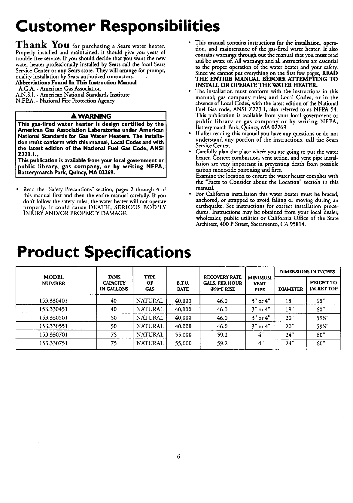
Product Specifications
MODEL
NUMBER TANK
CAPACITY
IN _NS
TYPE
OF
GAS B.T.U.
RATE
RECOVERY RATE
GALS. PER HOUR
@90°F RISE
153.330401 40 NATURAL 40,000 46.0
153.330451 40 NATURAL 40,000 46.0
153.330501 50 NATURAL 40,000 46.0
153.330551 50 NATURAL 40,000 46.0
153.330701 75 NATURAL 55,000 59.2
153.330751 75 NATURAL 55,000 59.2
MINIMUM
VENT
PIPE
3" or4"
3" or 4"
3" or 4"
3" or4"
4"
4"
DIMENSIONS IN INCHES
HEIGHT TO
DIAMETER JACKET TOP
18" 60"
18" 60"
20" 59½"
20" 59½"
24" 60"
24" 60"
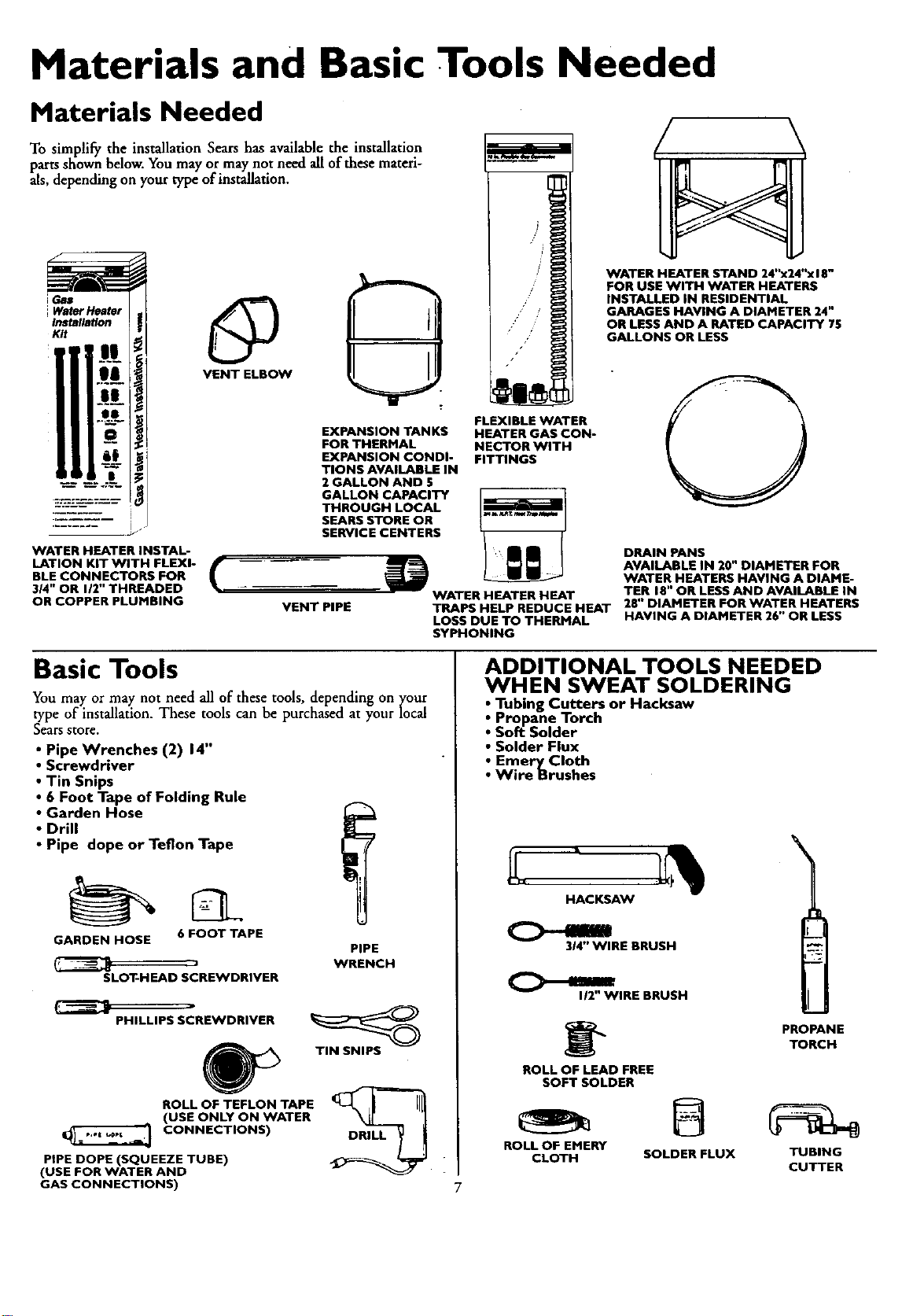
Materials and Basic Tools Needed
Materials Needed
To simplify the installation Sears has available the installation
parts shown below. Youmay ormay not need all of these materi-
als,depending on your type of installation.
iWater Heater
Installation
Kit
VENT ELBOW _.
WATER HEATER INSTAL-
LATION KIT WITH FLEXI- f
BLE CONNECTORS FOR
314" OR 112"THREADED
OR COPPER PLUMBING
EXPANSION TANKS
FOR THERMAL
EXPANSION CONDI-
TIONS AVAILABLE IN
2 GALLON AND 5
GALLON CAPACITY
THROUGH LOCAL
SEARS STORE OR
SERVICE CENTERS
WATER HEATER STAND 24"x24"x 18"
FOR USE WITH WATER HEATERS
INSTALLED IN RESIDENTIAL
GARAGES HAVING A DIAMETER 24"
OR LESS AND A RATED CAPACITY 75
GALLONS OR LESS
FLEXIBLE WATER
HEATER GAS CON-
NECTOR WITH
FITTINGS
VENT PIPE
DRAIN PANS
AVAILABLE IN 20" DIAMETER FOR
WATER HEATERS HAVING A DIAME-
WATER HEATER HEAT TER 18" OR LESS AND AVAILABLE IN
TRAPS HELP REDUCE HEAT 28" DIAMETER FOR WATER HEATERS
LOSS DUE TO THERMAL HAVING A DIAMETER 26" OR LESS
SYPHONING
Basic Tools
You may or may not need all of these tools, depending on ycour
type of installation. These tools can be purchased at your local
Sears store.
• Pipe Wrenches (2) 14"
•Screwdriver
•Tin Snips
•6 Foot Tape of Folding Rule
• Garden Hose
•Drill
•Pipe dope or Teflon Tape
GARDEN HOSE 6 FOOT TAPE
j
SLOT-HEAD SCREWDRIVER
PIPE
WRENCH
PHILLIPS SCREWDRIVER
ROLL OF TEFLON TAPE
(USE ONLY ON WATER
CONNECTIONS)
PIPE DOPE (SQUEEZE TUBE)
(USE FOR WATER AND
GAS CONNECTIONS)
TIN SNIPS
DRILL
ADDITIONAL TOOLS NEEDED
WHEN SWEAT SOLDERING
•Tubing Cutters or Hacksaw
•Propane Torch
• Soft Solder
•Solder Flux
•Emery Cloth
•Wire Brushes
HACKSAW
314"WIRE BRUSH
I/2" WIRE BRUSH
ROLL OF LEAD FREE
SOFT SOLDER
PROPANE
TORCH
ROLL OF EMERY
CLOTH SOLDER FLUX TUBING
CUTTER
?
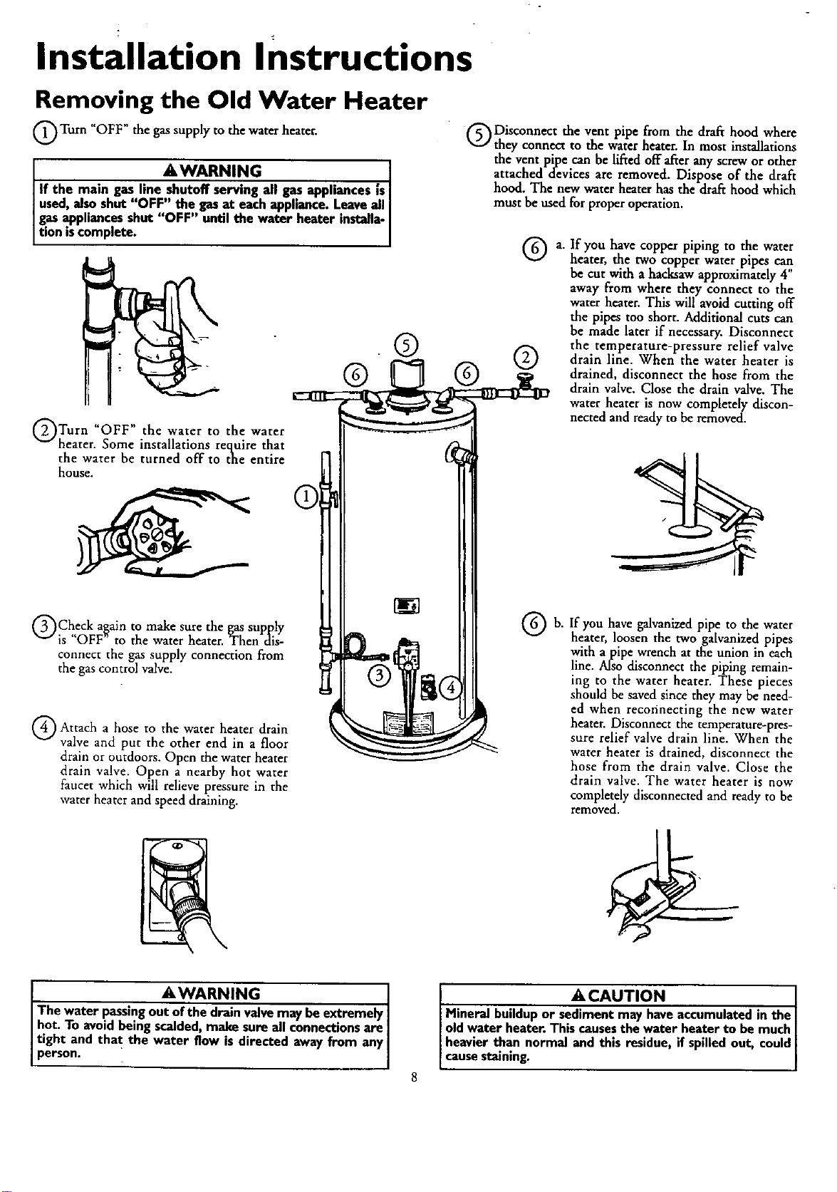
Installation Instructions
Removing the Old Water Heater
Turn "OFF" the gas supply to the water heater.
AWARNING o
If the main gas line shutoff serving all _appliances is
used, also shut "OFF" the gas at each appliance. Leave all
gas appliances shut "OFF" until the water heater installa-
t on s comp ete.
Turn water to water
"OFF" the the
heater. Some installations require that
the water be turned off to the entire
house.
Check again to make sure the gas supply
is "OFF" to the water heater. Then dis-
connect the gas supply connection from
the gas control valve.
('_Disconnect the vent pipe from the draft hood where
they connect to the water heater. In most installations
the vent pipe can be lifted offafter any screw or other
attached devices are removed. Dispose of the draft
hood. The new water heater has the draft hood which
must be used for proper operation.
®
® ®
Q Attach a to water heater drain
hose the
valve and put the other end in afloor
drain or outdoors. Open the water heater
drain valve. Open a nearby hot water
faucet which will relieve pressure in the
water heater and speed draining.
a. If you have copper piping to the water
heater, the two copper water pipes can
be cut with ahacksaw approximately4"
away from where they connect to the
water heater. This will avoid cutting off
the pipes too short. Additional cuts can
be made later if necessary. Disconnect
the temperature-pressure relief valve
drain line. When the water heater is
drained, disconnect the hose from the
drain valve. Close the drain valve. The
water heater is now completely discon-
nected andready to be removed.
Q b. you galvanized pipe to water
If have the
heater, loosen the two galvanized pipes
with apipe wrench at the union in each
line. Also disconnect the piping remain-
ing to the water heater. These pieces
should be saved since they may be need-
ed when recofinecting the new water
heater. Disconnect the temperature-pres-
sure relief valve drain line. When the
water heater is drained, disconnect the
hose from the drain valve. Close the
drain valve. The water heater is now
completely disconnected and ready to be
removed.
AWARNING ]
The water passingou_ve may be extremely]
hot. To avoidbeingscalded make sure all connectionsare|
tight and that the water flow is directed away from anyI
person, i J
ACAUTION J
Mineral buildup or sediment may have accumulated in the J
old water heater. This causes the water heater to be much
heavier than normal and this residue, if spilled out, could
cause staining.
Installation Instructions (cont'd)
Facts to Consider About the
Location
You should carefully choose an indoor location for the new
water heater, because the placement is avery important consid-
eration for the safety of the occupants in the building and for
the most economical use of the appliance. This water heater is
not for use in mobile homes or outdoor installation.
Whether replacing an old water heater or putting the water
heater in anew location, the following critical points must be
observed.
The location selected should be indoors as close as practical
to the gasvent or chimney to which the water heater vent is
going to be connected, and as centralized with the water pip-
ing system as possible. The water heater, as all water heaters,
will eventually leak. Do not install without adequate
drainageprovisions where water flow will cause damage.
ACAUTION
WATER HEATERS EVENTUALLY LEAK:Installationof the
water heatermust beaccomplishedin sucha mannerthat if
thetankor anyconnectionsshouldleak,the flowofwaterwill
not causedamageto the structure.When suchlocationscan-
not be avoided,a suitable drain panshouldbe installedunder
the water heater.Drain pansare availableat yourlocalSears
store.Sucha drain pan must be not greaterthan 1½inches
deep,havea minimum lengthand width of at least2 inches
greaterthan the water heaterdimensionsand must be piped
to anadequatedrain.The panmustnotrestrictcombustionair
flow.Under no circumstancesisthe manufactureror Searsto
be heldliablefor anywater damagein connectionwith this
water heater.
AWARNING
INSTALLATIONSIN AREASWHERE FLAMMABLELIQUIDS
VAPORS) ARE LIKELY TO BE PRESENT OR STORED
(GARAGES, STORAGE, AND UTILITY AREAS, ETC):
Flammableliquids(suchasgasoline,solvents,propane(LP)or
butane, etc.), all of whichemit flammable vapors,may be
improperlystoredor usedin suchareas.The gaswater heater
pilot lightor mainburnercanignitesuchvapors.The resulting
flashbackand Erecancausedeathor seriousbumsto anyonein
the area,aswellaspmpertydamage.
Ifinstallationin suchareasisyouronlyoption,thenthe installa-
tion must beaccomplishedin a way that the pilot flameand
mainburnerflameareelevatedfromthe floorat least18 incheg
While this may reducethe chancesofflammablevaporsfroma
floorspillbeingignited,gasolineandotherflammablesubstances
shouldneverbestored or usedin the sameroomor areacon-
taininga gaswater heateror otheropenflameor sparkproduc-
ingappliance.
NOTE: Flammablevaporsmay be drawnbyair currentsfrom
otherareasofthe structuretothe appliance.
AWARNING
Propellantsofaerosolspraysand volatilecompounds,(clean-
ers,chlorinebasedchemicals,refrigerants, etc.)inadditionto
being highlyflammable in manycases,will alsochangeto cor-
rosive hydrochloricacid when exposedto the combustion
,roducts ofthe water heater.The results canbe hazardous,
_d alsocauseproductfailure.
•The location selection must provide adequateclearancesforser-
vicing and properoperationof the waterheater.
AWARNING
This water heatermustnot be installeddirectlyon carpeting.
Carpeting must be protected by a metal or wood panel
beneaththe appliance extendingbeyondthe fullwidth and
depthof the applianceby at least3 inches(76.2mm) in any
direction,or if theapplianceisinstalledin an alcoveor closet,
theentirefloor mustbe coveredbythe panel.Failureto heed
thiswarningmayresult.inafirehazard.
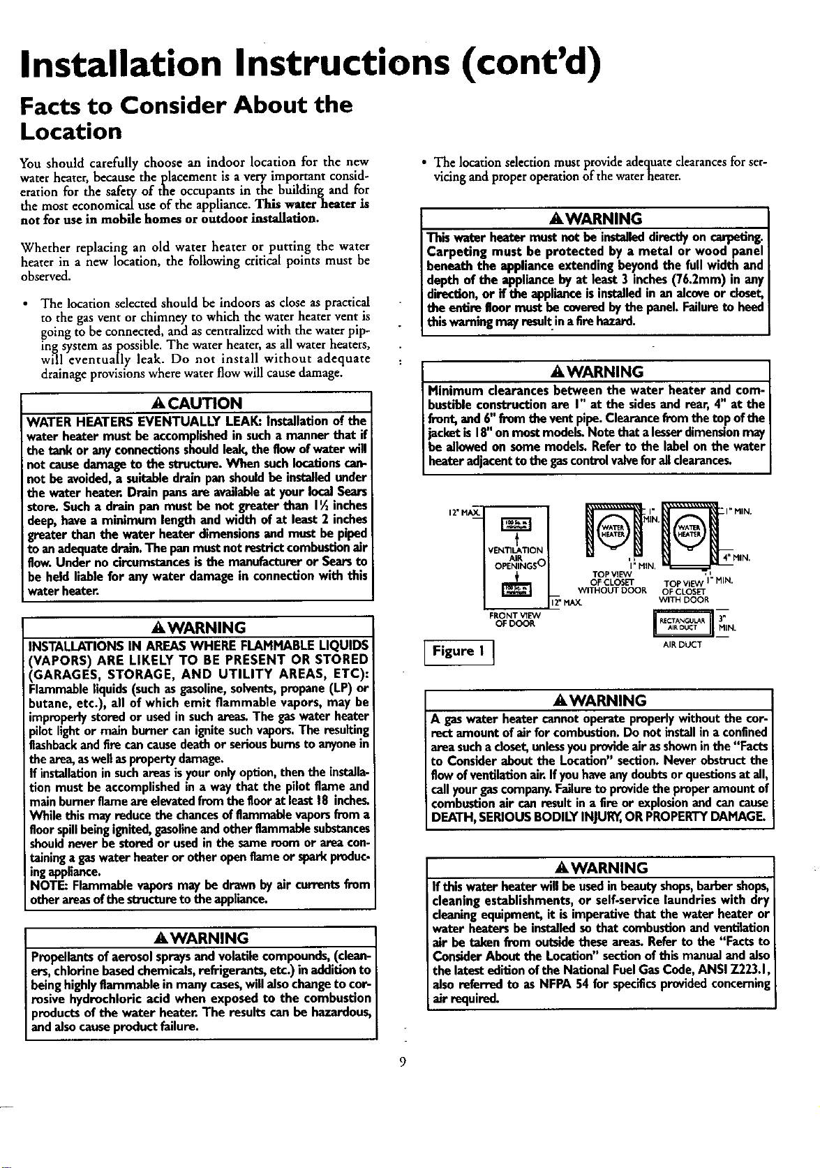
AWARNING
Minimum clearancesbetween the water heater and com-
bnstibleconstructionare I" at the sidesand rear, 4" at the
front,and 6"from theventpipe.Clearancefromthetopofthe
jacketis 18"on mostmodelgNotethata lesserdimensionmay
be allowedon somemodels.Referto the labelonthe water
heateradjacenttothe gascontrolvalveforall dearances.
12"MA_
t
VEN'rILATION
AIR
OPENINGS O
+
FRONT VIE'vV
OF DOOR
Figure I ]
OF CLOSET TOP VIEW I" NIN.
WITHOUT DOOR OF CLOSET
_" MAX. WITH DOOR
-AIR DUCT
AWARNING
A gaswater heatercannotoperateproperlywithoutthecor-
rect amount ofair forcombustion.Do notinstallin a confined
areasucha doset,unlessyou provideair asshowninthe "Facts
to Considerabout the Location"section.Never obstructthe
flowofventilationair.Ifyouhaveanydoubtsor questionsat all,
callyourgascompany.Failureto providetheproperamount of
combustionair canresultin a fire or explosionand cancause
DEATH,SERIOUSBODILYINJUR_,ORPROPERTYDAMAGE.
AWARNING
If this water heaterwill be usedinbeauty shops,barbershops,
cleaningestablishments,or self-servicelaundrieswith dry
cleaningequipment, it isimperativethat the waterheater or
water heatersbe installedsothat combustionand ventilation
air be takenfrom outsidetheseareag Referto the "Facts to
ConsiderAboutthe Location"sectionofthis manualandalso
thelatestedition oftheNationalFuelGasCode,ANSIZ223.1
also referredto asNFPA54 for specificsprovidedconcernin
air required.
Installation InStructions (cont'd)
Combustion Air and Ventilation
for Appliances Located in
Unconfined Spaces
Uncon_qned Space is a space whose volume is not less than 50
cubic feet per 1,000 Btu per hour of the aggregate input rating
of all appliances installed in that space. Rooms comuiunicatin_
directly with the space in which the appliances are installed,
through openings not furnished with doors, are considered a
part of the unconfined space
In unconfined spaces in buildings, infiltration may be adequate
to provide air for combustion, ventilation and dilution of flue
gases. However, in buildings of tight construction (for example,
weather stripping, heavily insulated, caulked, vapor barrier, etc.),
additional air may need to be provided using the methods
described in Comb.ustion Air and Ventilation_ for Appliances
Located in Confined Spaces, b.
Combustion Air and Ventilation
for Appliances Located in
Confined Spaces
Confined Space is a space whose volume is less than 50 cubic
feet per 1,000 Btu per hour of the aggregateinput rating of all
appliances installed in that space.
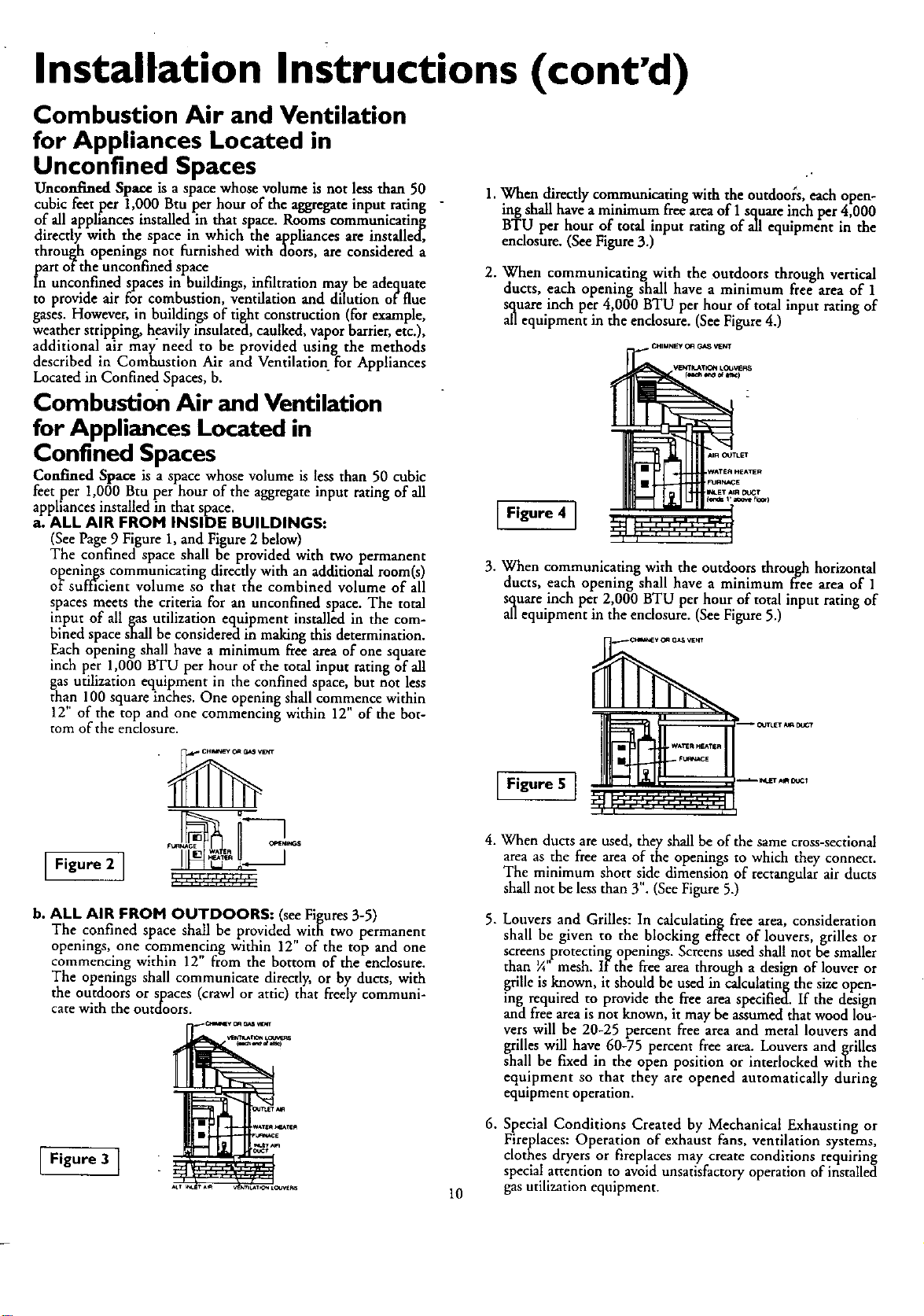
a. ALL AIR FROM INSIDE BUILDINGS:
(See Page 9Figure 1, and Figure 2below)
The confined space shall be provided with two permanent
openings communicating directly with an additional room(s)
of sufficient volume so that the combined volume of all
spaces meets the criteria for an unconfined space. The total
input of all gas utilization equipment installed in the com-
bined space shall be considered in making this determination.
Each opening shall have aminimum free area of one square
inch per 1,000 BTU per hour of the total input rating of all
gas utilization equipment in the confined space, but not less
than 100 square inches. One opening shall commence within
12" of the top and one commencing within 12" of the bot-
tom of the enclosure.
b. ALL AIR FROM OUTDOORS: (see Figures 3-5)
The confined space shall be provided with two permanent
openings, one commencing within 12" of the top and one
commencing within 12" from the bottom of the enclosure.
The openings shall communicate directly, or by ducts, with
the outdoors or spaces (crawl or attic) that freely communi-
cate with the outdoors.
IFigure 31
1. When directly communicating with the outdoolS, each open-
ing shall have a minimum free area of 1square inch per 4,000
BTU per hour of total input rating of all equipment in the
enclosure. (See Figure 3.)
2. When communicating with the outdoors through vertical
ducts, each opening shall have a minimum free area of 1
square inch per 4,000 BTU per hour of total input rating of
all equipment in the enclosure. (See Figure4.)
• CHIMNEY O_ _VENT
IFigure 4 ]
10
3. When communicating with the outdoors through horizontal
ducts, each opening shall have a minimum free area of 1
square inch per 2,000 BTU per hour of total input rating of
all equipment in the enclosure. (See Figure 5.)
4. When ducts are used, they shall be of the same cross-sectional
area as the free area of the openings to which they connect.
The minimum short side dimension of rectangular air ducts
shall not be less than 3". (See Figure 5.)
.Louvers and Grilles: In calculating free area, consideration
shall be given to the blocking effect of louvers, grilles or
screens protecting openings. Screens used shall not be smaller
than ¼" mesh. If the free area through adesign of louver or
grille is known, it should be used in calculating the size open-
ing required to provide the free area specified. If the design
and free area is not known, it may be assumed that wood lou-
vers will be 20-25 percent free area and metal louvers and
grilles will have 60-75 percent free area. Louvers and grilles
shall be fixed in the open position or interlocked with the
equipment so that they are opened automatically during
equipment operation.
6. Special Conditions Created by Mechanical Exhausting or
Fireplaces: Operation of exhaust fans, ventilation systems,
clothes dryers or fireplaces may create conditions requiring
special attention to avoid unsatisfactory operation of installed
gas utilization equipment.
Installation Instructions (cont'd)
Water Piping
AWARNING
HOTTERWATERCANSCALD:.Water heatersam intendedto
producehot water.Water _ to a temperaturewhichwill
sat_fyclotheswashing,dishwashing,andothersanitizingneeds
canscaldandpermanentlyinjureyouuponcontact.Somepeo-I
piearemorelikelyto bepermanentlyinjured byhotwaterthan
others.Theseincludeth_elder_ cin_lren,theinfirm,or physical-
ly/mentallyhandicapped.Ifanyoneusinghotwaterinyourhome
Etsintooneofthesegroupsor ifthereisalocalcodeorstateI_v
reclulrlngacertaintemperaturewateratthehotwater_ then
youmusttakespecialprecaution_In additionto usingthelowest
possibletemperaturesettingthatsatisfiesyourhotwaterneeds,
a meanssuchasa mixingvalve,shouldbe usedat the hotwater
tapsusedbythesepeopleor at the waterheater.Mixingvalves
areavailableat plumbingsupplyor hardwarestore_ Followman.
ufacturersinstructionsfor installationof the valves.Before
changingthe factory setting on the thermostat, read the
"TemperatureRegulation"sectioninthis manual.
This water heater shall not be connected to any heating systems or
component(s) used with a non-potable water beating appliance.
If awater heater is installed in a closed water supply system;
such as one having aback-flow preventer, check valve, water
meter with acheck valve, etc.., in the cold water supply; means
shall be provided to control thermal expansion. Contact the
local utility or local Sears Service Center on how to control this
situation,
NOTE: To_protect against untimely corrosion of hot and
cold water fittings, it is strongly recommended that dl-elec-
tric unions or couplings be installed on this water heater
when connected to copper pipe.
The illustration shows the attachment of the water piping to the
water heater. The water heater is equipped with ¾" water con-
nections.
NOTE: If using copper tubing, solder tubing to an adapter
before attaching the adapter to the cold water inlet connec-
tion. Do not solder the cold water supply line directly to the
cold water inlet. It will harm the dip tube and damage the
tank.
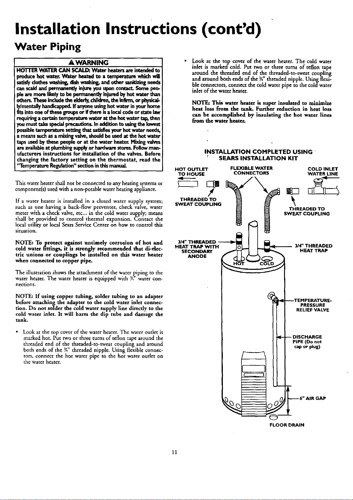
•Look at the top cover of the water heater. The water outlet is
marked hot. Put two or three turns of teflon tape around the
threaded end of the threaded-to-sweat coupling and around
both ends of the _A"threaded nipple. Using flexible connec-
tors, connect the hot water pipe to the hot water outlet on
the water heater.
•Look at the top cover of the water heater. The cold water
inlet is marked-cold. Put two or three turns of teflon tape
around the threaded end of the threaded-to-sweat coupling
and around both ends of the 3A"threaded nipple. Using flexi-
ble connectors, connect the cold waterpipe to the coldwater
inlet of the water heater.
NOTE: This water heater is super insulated to minimize
heat loss from the tank. Further reductmn in heat loss
can be accomplished by insulating the hot water lines
from the water heater.
INSTALLATION COMPLETED USING
"SEARS INSTALLATION KIT
HOT OUTLET
TO HOUSE FLEXIBLE WATER COLD INLET
CONNECTORS WATER LINE
I lg3
THREADED TO
SWEAT COUPLING
THREADED TO
SWEAT COUPLING
HEAT TRAP WITH IolA _314" THREADED
SECONDARY _I]_HEAT TRAp
ANODE
FLOOR DRAIN
--TEIqPERATURE-
PRESSURE
RELIEF VALVE
DISCHARGE
PIPE (Do not
cap or plug)
--6" AIR GAP
11
Installation InstruCtions (cont'd)
Temperature-Pressure Relief Valve
A WARNING
At the time of manufacturethis water heater was provided
with acombinationtemperature-pressuresreliefvalvecertified
by a nationallyrecognizedtestinglaboratorythat maintains
periodic mspec_onof productionof listedequipmentor mate-
rials, as meeting the requirements for Relief Valvesand
AutomaticGasShutoffDevicesfor Hot Water SupplySystems,
and the latesteditionof ANSI Z21.22 andthe coderequire-
meritsof ASME.If replaced,the valvemustmeet the require-
mentsoflocalcodes,but not lessthan a combinationtempera-
ture and pressurereliefvalvecertifiedasmeetingthe require-
ments for ReliefValvesandAutomaticGasShutoffDevicesfor
Hot Water SupplySystems,ANSI Z21.22bya nationallyrecog-
nized testinglaboratorythat maintainsperiodicinspectionof
productionoflistedequipmentor material_
The valvemustbemarkedwit(1a maximumset pressurenot
to exceedthe marked hydrostaticworking pressureofthe
waterheater(150 IbsJsq.in.)and a dischargecapacitynot less
thanthewaterheaterinputrateasshownonthe modelrating
plate.(Electricheaters- watts dividedby 1000x 3415 equal
BTU/Hr.rate.)
Yourlocaljurisdictionalauthority,whilemandatingthe useofa
temperature-pressurerelief valvecomplyingwith ANSIZ21.22
and ASME,mayrequireavalvemodeldifferentfrom theone
furnishedwiththe waterheater.
Compliancewith suchlocalrequirementsmustbesatisfiedby
the installeror enduserofthewater heaterwith a locallypre-
scribedtemperature-pressurereliefvalveinstalledinthedesig-
nated openingin the water heaterin placeof the factoryfur-
nishedvalve.
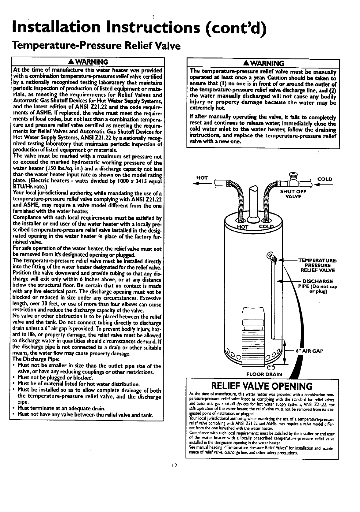
Forsafeoperationofthe waterheater,the reliefvalvemustnot
beremovedfromit'sdesignatedopeningor plugged.
The temperature-pressurerelief valvemust be installeddirectly
intothefittingofthewaterheaterdesignatedfor thereliefvalve.
Positionthe valvedownwardand providetubingsothatanydis-
chargewillexit onlywithin 6 inchesabove,or at anydistance
belowthe structuralfloor.Becertainthat nocontactismade
withanyliveelectricalpart.The dischargeopeningmustnotbe
blockedor reduced in sizeunderanycircumstances.Excessive
length,over 30feet,or useofmorethan fourelbowscancause
restriction andreducethedischargecapacityofthevalve.
No valveor otherobstructionisto be placedbetweentherelief
valveandthe tank.Do not connecttubingdi_ctly to discharge
drainunlessa 6"airgapisprovided.Topreventbodilyinjury,haz-
ard to life,or propertydamage,the reliefvalvemustbeallowed
todischargewaterinquantitiesshouldcircumstancesdemand.If
the dischargepipeisnot connectedto a drainor othersuitable
means,the waterflowmaycausepropertydamage.
The DischargePipe:
• Mustnot be smallerin sizethan the outlet pipesizeofthe
valve,or haveanyreducingcouplingsorotherrestrlction_
•Mustnot bepluggedorblocked.
Mustbeofmateriallistedfor hotwaterdistribution.
Must be installedsoasto allowcompletedrainageof both
the temperature-pressurerelief valve, and the discharge
pipe.
Mustterminateat anadequatedrain.
Mustnot haveanyvalvebetweenthe reliefvalvaandtank.
&WARNING
The temperature-pressure relief valve must be manually
operated at leastonce a year.Cautionshouldbe taken to
ensurethat (I) no one isin front ofor aroundthe outlet of
the temperature-pressure reliefvalvedischargeline,and (2)
the water manually dischargedwill not causeany bodily
injury or property damage because the water may be
extremelyhot.
ff after manuallyoperatingthe valve, it fails.to completely
resetand continuesto releasewatar, immedmatelyclosethe
cold water inlet to the water heater, follow the draining
instructions,and replace the temperature-pressurerelief
valvewith anewone.
HOT
SHUT OFF
VALVE
COLD
)_ PRESSURE
RELIEF VALVE
PIPE (Do not cap
or plug)
FLOOR DRAIN
RELIEFVALVEOPENING
At thetimeof manufacture,thiswaterheaterwasprovidedwithacombinationtem-
perature-pressurereliefvalvelistedascomplyingwith the standardfor reliefvalves
andautomaticgasshut-offdevicesfor hotwatersupplysystems,ANSIZ2}.22.For
safeoperation of the water heater,the relief valvemust not be removed from itsdes-
Fgnatedpointofinstallationorplugged.
Your localiurisdictional authority,while mandating the use of a temperature-pressure
relief valvecomplyingwith ANSI Z21.22 andASME, mayrequirea valvemodel differ-
entfrom the one furnished with the water heater
Compliancewith suchlocal requirementsmust be satisfiedby the instalieror end user
of the water heater with a locally prescribed temperature-pressure relief valve
instaJledinthe designatedopeningin the water heater
See manual heading-"Temperature-Pressure ReliefValves"for installationand mainte-
nance of relief valve, dischargeline, and other safetyprecautions.
]2
Installation Instructions (cont'd)
Filling the Water Heater
ACAUTION I
Never usethiswater heat_' unlessit mcompletelyfilledwith I
wa_. To_ont dam_etothetank,thetankmustbeelk_I
with water. Water must flow from the hot water faucet
beforeturning"ON" gasto thewater hea_.
For proper venting in certain installations, a largerdiameter vent
pipe may be necessary. Due to great variances in installations,
un-foreseeable by the manufacturer of the water heater, you must
consult your gas company to aid you in determining the proper
venting for your water heater from the vent tables in the latest
edition of the National Fuel Gas Code ANSI Z223.1, also
referred to as NFPA 54.
To fill the water heater with water:
•Close the water heater drain valve by turning the handle to
the right (clockwise). The drain valve is on the lower front of
the water heater.
Open the cold water supply valve to the water heater.
NOTE: The cold water supply valve must be left open
when the water heater is in use.
To insure complete filling of the tank, allow air ro exit by
opening the nearest hot water faucet. Allow water to run
until a constant flow is obtained. This will let air out of the
water heaterand the piping.
Check allnew water piping for leaks. Repairas needed.
Venting
_E,WARNING
VENT DAMPERS- Any ventdamper,whetherit isoperated
thermally or otherwisemustberemom_lifitsuseinhibitsprop-
er draftingofthewaterheater.
ThermallyOperated Vent Damper_ Gas-firedwater heaters
havingthermal efEciencyinexcessof 80%mayproducearein.
tively lowfluegastemperature.Suchtemperaturesmaynot be
high enough to properly open thermally operated vent
damper_Thiswouldcausespillageof Iluegasesandmaycause
carbonmonoxidepoisoning.
Ventdampersmust bearevidenceofcertificationascomplying
with the latesteditionof American NationalStandardANSI
Z21.68 (ANSI 7.21.66& 67, respectively,coverelectricallyand
mechanicallyactuatedvent dampers).Beforeinstallationofany
ventdamper,consultyourlocalSearsServiceCenteror thegas
utilityforfurtherinformation.
AWARNING
To insureproperventingof this gas-firedwater heater,the
correctventpipediametermust beutilized.Any additionsor
deletions ofothergasapplianceson a commonventwiththis
water heatermay adverselyaffectthe operationofthewater
heater.Consultthe localSearsServiceCenter or gasutilityif
anysuchchangesareplanned.
Check the venting system for signs of obstruction or deteriora-
tion and replace if needed.
The combustion andventilation air flow must not be obstructed.
, AWARNING
Ob.structedor deterioratedventsystemsmaypresentaserious
Ihealthrisk or asphyxiation.
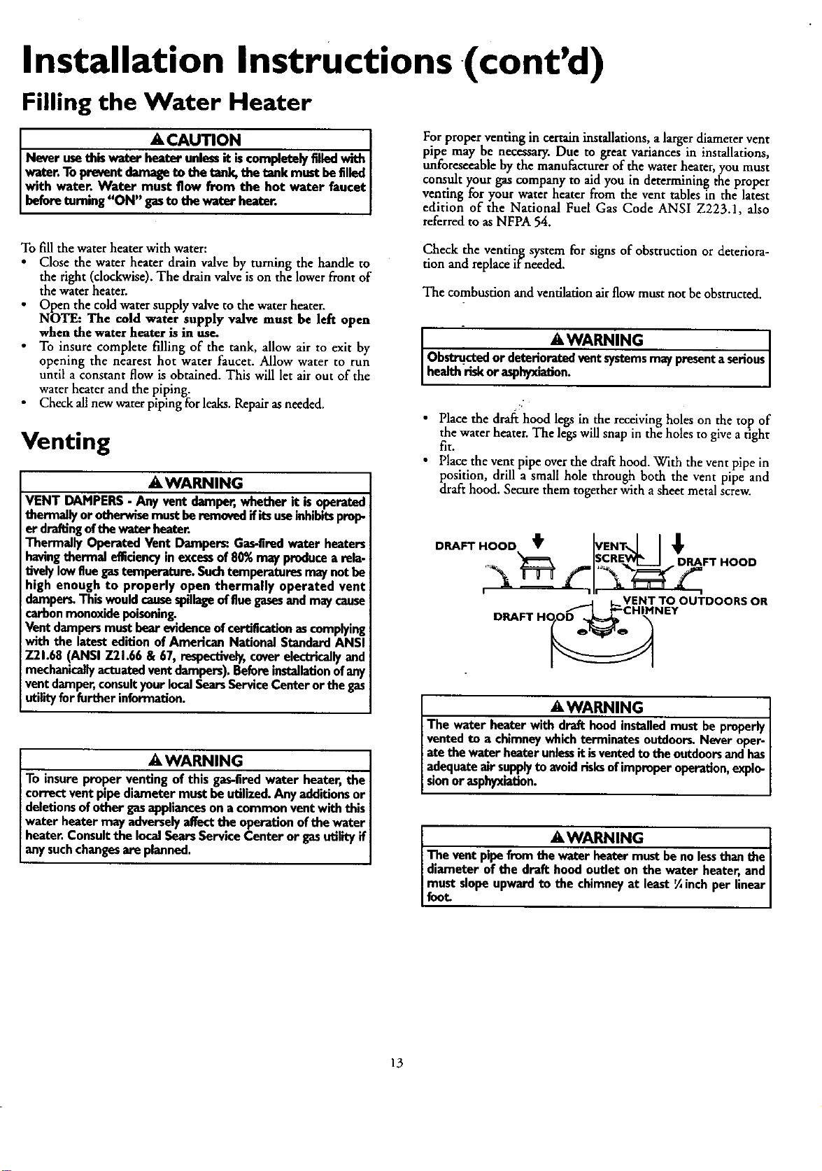
•Place the draft hood legs in the receiving holes on the top of
the water heater. The legs will snap in the holes to givea tight
fit.
• Place the vent pi.peoverthe draft hood. With the vent pipe in
position, drill a small hole through both the vent pipe and
draft hood. Secure them together with a sheet metal screw.
DRAFT HOOD t _VENT,,,,]
,_ISCREV¢____IDRAFTHOOD
DRAFT HO_ TNTOOUTDOORS OR
AWARNING
The water heaterwit_lled mustbeproperlyI
ventedto a chimneywhichterminatesoutdoors.Neveroper-
atethe waterheaterunlessitisventedto the outdoorsandhas
adequateairsupplytoavoidrisksofimproperoperation,explo-
sionoresphyxiation. [
AWARNING [
The vent pipefromthe waterheatermustbeno lessthanthe I
diameter of the draft hoedoutlet on the water heater, and
mustslopeupwardto the chimneyat least'/4inchper linear
foot
13
Installation Instructions (cont'd)
Venting (cont'd)
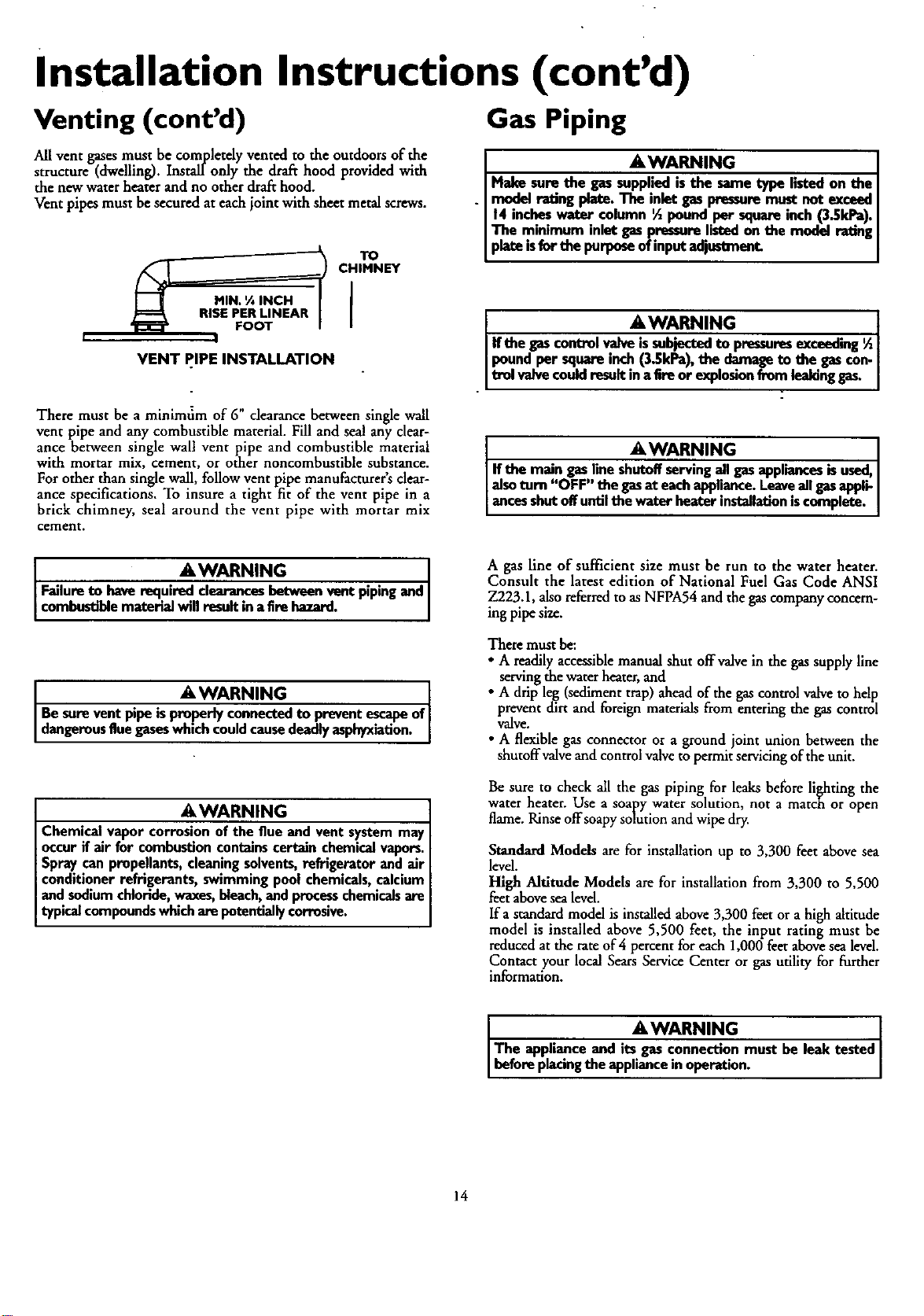
All vent gases must be completdy vented to the outdoors of the
structure (dwelling). InstaU only the drafthood provided with
the new water heater and no other drafthood.
Vent pipes must be secured at each joint with sheet metal screws.
TO
CHIMNEY
VENT PIPE INSTALLATION
Gas Piping
AWARNING
Make sorethe gassuppliedis the sametype listedon the
model rating plate.The inletgaspressuremustnot exceed
14 incheswater column ½poundper squareinch(3.SkPa).
The minimum inlet gaspressurelistedon the model ratin
plateisfor thepurposeofinputadj_
AW.A.RNING [
Ifthe gascontrolvalveissubjectedto pressuresexceeding ½[
pound per square inch(3.SkPa),the damageto the gascon-[
[trel valvecouldresultin aEreor explosionfrom leakingga_
There must be a minimfim of 6" clearance between single wall
vent pipe and any combustible material. Fill and seal any clear-
ance between single wall vent pipe and combustible material
with mortar mix, cement, or other noncombustible substance.
For other than single wall, follow vent pipe manufacturer's dear-
ance specifications. To insure a tight fit of the vent pipe in a
brick chimney, seal around the vent pipe with mortar mix
cement.
AWARNING [
If the main gaslineshutoffservingallgasappliancesisused,[
alsoturn "OFF" thegasat eachappliance.Leaveallgasappli-
ancesshutoffuntilthe water heater installationiscomplete.
AWARNING
Failureto haverequiredclearancesbetweenvent pipingand
combustiblematerialwillresultinafire hazard.
AWARNING [
Besureventpipeisproperlyconnectedto preventescapeof
dangerousfluegaseswhichcoud causedeadlyasphyxation.
AWARNING
Chemical vapor corrosionofthe flue and vent systemmay
occurif air for combustioncontainscertainchemicalvapors.
Spraycanpropellants,cleaningsolvents,refrigerator and air
conditionerrefrigerants, swimmingpool chemicals,calcium
and sodiumchloride,waxes,bleach,and processchemicalsare
typicalcompoundswhicharepotentially corrosive.
A gas line of sufficient size must be run to the water heater.
Consult the latest edition of National Fuel Gas Code ANSI
Z223.1, alsoreferred to as NFPA54 and the gascompany concern-
ing pipe size.
There must be:
•Areadilyaccessible manual shut offvalve in the gas supply line
serving the water heater, and
•Adrip leg (sediment trap) ahead of the gascontrol valve to help
prevent dirt and foreign materials from entering the gas control
valve.
•A flexible gas connector or aground joint union between the
shutoffvalve and control valveto permit servicingof the unit.
Be sure to check all the gas piping for leaks before lighting the
water heater. Use a soapy water solution, not a match or open
flame. Rinse offsoapy solution and wipe dry.
Standard Models are for installation up to 3,300 feet above sea
level.
High Altitude Models are for installation from 3,300 to 5,500
feet above sea level.
Ifa standard model is installed above 3,300 feet or a high altitude
model is installed above 5,500 feet, the input rating must be
reduced at the rate of 4 percent for each 1,000 feet above sea level.
Contact your local Sears Service Center or gas utility for forther
information.
AWARNING
The appliance and its gasconnectionmust be leak tested
beforeplacngthe appliancein operation.
14
Installation Instructions (cont'd)
AWARNING
•The applianceanditsindividualshutoffvalvemustbediscon-
nectedfromthe gassupplypiplngsystemduringanypressure
testingof the gassystemat test pressuresin excessof
poundpersquareinch(3.SkPa). ..
• The appiiancemustbeisulatedfromthegassuppiyIxl_ngsys-
tem bydosingi_ individualmanualshutoff valveduringany
pressuretestingofthe gassupplypipingsystemat trot pres-
suresequalor lessthan_poundpersquareinch(3.SkPa).
GAS PIPING WITH
FLEXIBLE CONNECTOR
LOOP
GROUND GAS
_'ONTROL
VALVE
AWARNING [
Use pipe joint compound or teflon tape marked as being[
resistanttothe acUonofpetroleum [Propane(LR)] gase_ [
DRIP LEG
(Sedimenttrap)
CAP
SEDIMENT TRAP
A sediment trap shall be installed as close to the inlet of the
water heater as practical at the time of water heater installation.
The sediment trap shall be either atee fitting with acapped nip-
ple in the bottom outlet or other device recognized as an effec-
tive sediment trap. Ifa tee fitting is used, it shall be installed in
conformance with one of the methods of installation shown
below.
Connecting the gas piping to the gas control valve of the water
heater can be accomplished by either of the two methods shown.
AWARNING
Contaminantsin thegaslinesmay causeimproperoperation
of the gascontrolvalvethat may resultin fire or explosion.
Beforeattachingthegaslinebesurethat all gaspipeisclean
on the inside.Totrap anydirt or foreign material in the gas
supplyline, a drip leg (sometimes calleda sedimenttrap)
must be incorporated in the piping.The drip leg must be
readilyaccessible.Installin accordancewith the "Gas Piping"
section.Referto the latesteditionof the NationalFuelGas
Code,ANSI 7.223.1,alsoreferred toasNFPA54.
GAS PIPING WITH ALL BLACK IRON
PIPE TO GAS CONTROL
GROUND JOINT "_ BLACK PIPE
3 min._ (Se_D'RmIPntLEt_ap)tjCAP
GAS
CONTROL
VALVE
15
Installation Instructions (cont'd)
Installation Checklist
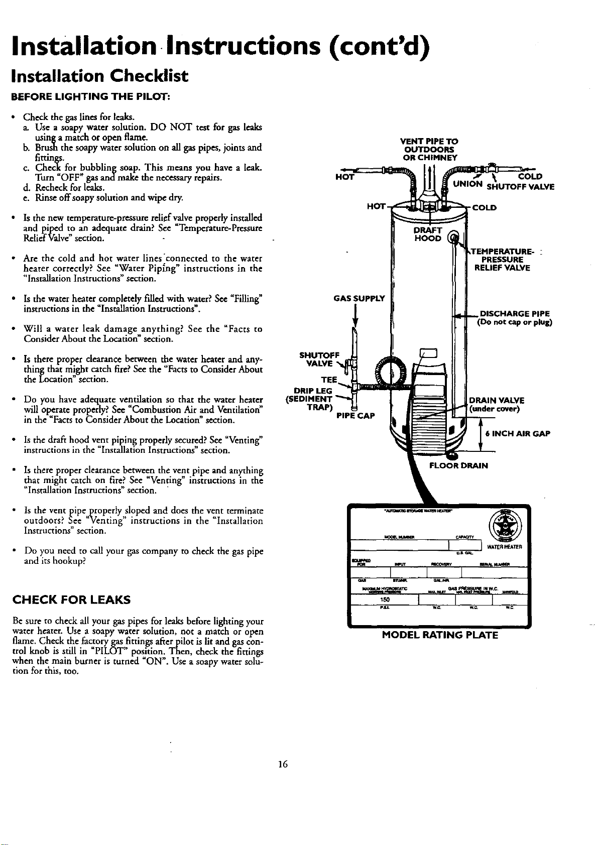
BEFORE LIGHTING THE PILOT:
Check the gas lines for leaks.
a. Use a soapy water solution. DO NOT test for gas leaks
usinga match oropen flame.
b. Brush the soapy water solution on all gas pipes, joints and
fittings.
c. Check for bubbling soap. This means you have a leak.
Turn OFF _gas andmake the necessaryrepairs.
d. Recheck for leaks.
e. Rinse offsoapy solution and wipe dry.
Is the new temperature-pressure relief v_ve properly installed
and piped to an adequate drain? See Temperature-Pressure
Relief Valve section.
HOT
HOT-
VENT PIPE TO
OUTDOORS
OR CHIMNEY
•Are the cold and hot water lines'connected to the water
heater correctly? See "Water Pip_ng" instructions in the
c. . ..
Installat on Instruct ons section.
•Is the water heatercompletely filled with water? See _Filling"
instructions in the Installation Instructions. GAS SUPPLY
•Will a water leak damage anything? See the "Facts to
Consider About the Location section.
•Is there proper clearance between the water heater and any-
thing that m!ght catch fire?See the "Facts to Consider About
the Location section.
• Do you have adequate ventilation so that the water heater
will operate properly? See _Corabustion Air and Ventilation"
in the "Facts to Consider About the Location"section,
SHUTOFF
VALVE
TEE,
DRIP LEG
TRAP) PIPE CAP
• Is the draft hood vent piping properly secured? See _Venting"
instructions in the "Installation Instructions" section.
•Is there proper clearance between the vent pipe and anything
that might catch on fire? See "Venting" instructions in the
"Installation Instructions" section. "
• Is the vent pipeproperty sloped and does the vent terminate
outdoors? See "Venting" instructions in the "Installation
Instructions" section.
• Do you need to call your gas company to check the gas pipe
and its hookup?
COLD
UNION SHUTOFF VALVE
• COLD
2
PRESSURE
RELIEF VALVE
DISCHARGE PIPE
(Do not cap or plug)
DRAIN VALVE
6 INCH AIR GAP
FLOOR DRAIN
CHECK FOR LEAKS
Be sure to check all your gas pipes for leaks before lighting your
water heater. Use a soapy water solution, not amatch or open
flame. Check the factory gas fittings afterpilot is lit and gas con-
trol knob is still in "PILOT" position. Then, check the fittings
when the main burner is turned "ON". Use a soapy water solu-
tion for this, too.
MODEL RATING PLATE
16
Operating Instructions
Lighting
AWARNING
BEFORELIGHTING PROPANE(L.R)GASWATERHEATERS:
Propane(LR) gasis beevierthanair.Shouldti_re bea le_kin
the system,the gaswill settle near the ground.Basements,
crawl spaces,skirtedareasunder mobilehomes(evenwhen
ventilated),closetsand areasbelowgroundlevelwill serveas
pocketsfor the accumulationofthis 8_ Beforeat_emFdngto
lightor mlight the water heater'spilotor turningon anearby
electricaJlightswitch,be abeolutelysumthere isno accumulat-
ed gasin theare_ Searchfor odorof gasbymimngst ground
levelin thevicinityofthe appliance.If odor isdetected,follow
stepsindicatedat "For YourSafety"onthe coverpageofthis
manualthenleavethe premise_
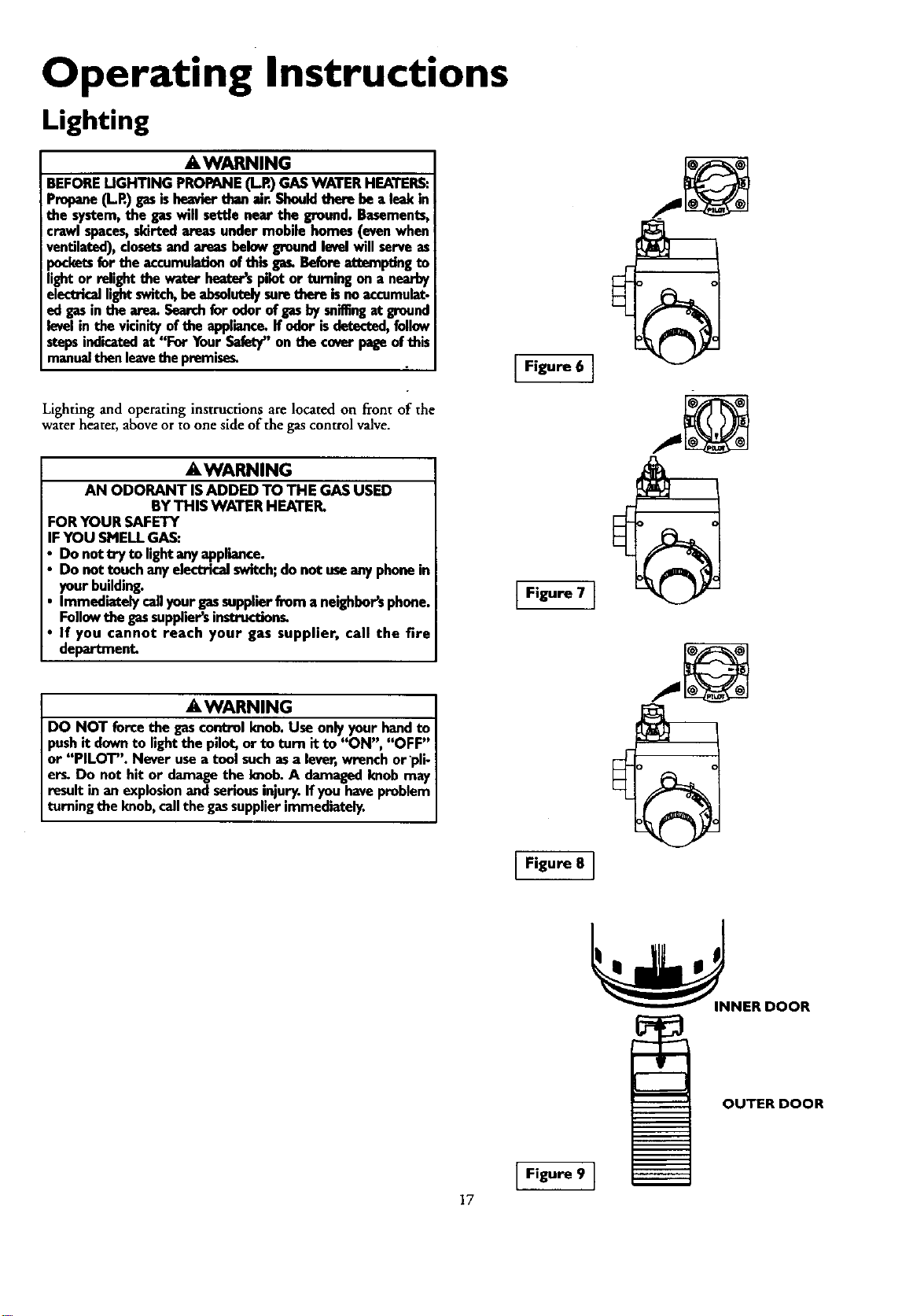
Lighting and operating instructions are located on front of the
water heater, above or to one side of the gas control valve.
AWARNING
AN ODORANT ISADDED TO THE GAS USED
BYTHIS WATER HEATER.
FORYOUR SAFETY
IFYOU SMELLGAS:
Do nottry to lightany appliance.
Do not touch anyelectTicalswitch;do not useanyphonein
yourbuilding.
Immediatelycallyour gassupplierfrom a neighbor'sphone.
Followthe gassuppiier_instruct_n_
If you cannot reach your gas supplier, call the fire
department.
_,WARNING
DO NOT force the gascontrolknob.Useonlyyour handto
pushit downto lightthe pilot,or to turn it to "ON", "OFF"
or "PILOT". Never usea tool suchasa lever,wrenchor pli-
er_ Do not hit or damagethe knob. A damagedknobmay
resultin an explosionand serious injury.Ifyou haveproblem
turningthe knob, callthegassupplierimmediately.
IFigure 6 ]
Figure 7 }
Figure 8 ]
OUTER DOOR
Figure 9 }
17
Operating Instructions (cont'd)
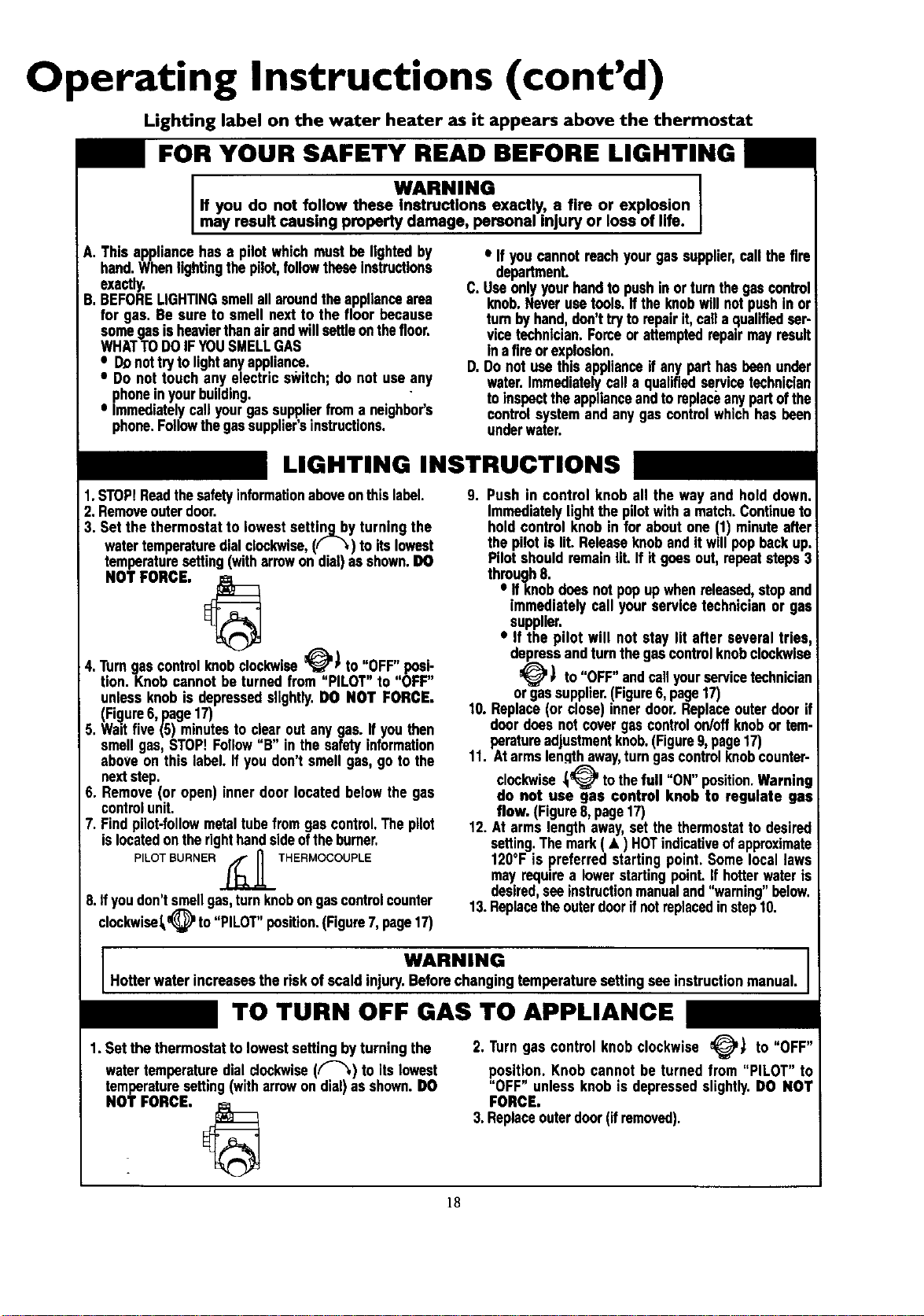
Lighting label on the water heater as it appears above the thermostat
FOR YOUR SAFETY READ BEFORE LIGHTING
A.
B.
WARNING
If you do not follow these Instructions exactly, a fire or explosion
may result causing property damage, personal injury or loss of life.
Thisappliancehas a pilotwhichmust be lightedby
hand.Whenlightingthepilot,followtheseinstructions
exactly.
BEFORELIGHTINGsmellall aroundthe appliancearea
for gas. Be sure to smell nextto the floor because
somegasisheavierthanairandwillsettleonthefloor.
WHATTODOIFYOUSMELLGAS
• D.onot tryto lightanyappliance.
•Do not touch any electrics_kitch;do not use any
phoneinyourbuilding.
•Immediatelycallyourgassupplierfroma neighbor's
phone.Followthegassupplier'sinstructions.
•If youcannotroachyourgas supplier,call thefire
department.
C.Useonlyyourhandto pushinor turnthegascontrol
knob.Neverusetools.Ifthe knobwillnotpushin or
turnbyhand,don'ttryto repairit, cell a qualifiedser-
vicetechnician.Forceor attemptedrepairmayresult
in afireorexplosion.
D. Donot usethis applianceif anypart hasbeenunder
water.Immediatelycall a qualifiedsel'vicetechnician
to inspecttheapplianceandtoreplaceanypartofthe
controlsystemandanygas controlwhichhasbeen
underwater.
LIGHTING INSTRUCTIONS
1.STOP!Readthesafetyinformationaboveonthislabel.
2. Removeouterdoor.
3. Setthe thermostat to lowestsettinq.byturning the
watertemperaturedialclockwise,(,'- _,)to itslowest
temperaturesetting(witharrowondial)as shown.DO
NOT FORCE,
4.Turngascontrolknobclockwise_PI to "OFF" posi-
tion. Knob cannotbe turnedfrom "PILOT" to "OFF"
unlessknobis depressedslightly.OO NOT FORCE.
(Fi_lure6,page17)
5. Waltfive(5) minutestoc!e.a,rout anygas. Ifyou then
I
smell9as,STOP.Follow B inthe safetyinformation
aboveon this label. If youdon't smellgas, go tothe
nextstep.
6. Remove(or open)inner door locatedbelowthe gas
controlunit.
7. Findpilot-followmetaltubefromgascontrol,Thepilot
islocatedontherighthandsideoftheburner,
PILOT BURNER _,_ _ THERMOCOUPLE
8.ff you don't smellgas,turn knobongas controlcounter
clockwise_#-,_l_,)to "PILOT"position.(Figure7,page17)
9. Push in control knob all the way and hold down.
Immediatelylightthe pilotwitha match.Continueto
hold controlknobin for aboutone (1) minuteafter
thepilotis lit.Releaseknobandit willpop beck up.
Pilotshouldremainlit. If if goesout,repeatsteps3
through8.
•If knobdoesnotpopupwhenreleased,stopand
immediatelycall yourservicetechnicianor gas
supplier.
•If the pilot will not stay lit after several tries,
depressandturnthegascontrolknobclockwise
_' ) to"OFF" andcallyourservicetechnician
or gassupplier.(Figure6,page17)
10.Replace(or close)innerdoor.Replaceouterdoor if
doordoesnotcovergascontrolon/offknobor tem-
peratureadjustmentknob.(Figure9,page17)
11. Atarmslengthaway,turngascontrolknobcounter-
clockwise_tothefull "ON" position. Warning
do not use gas control knob to regulate gas
flow. (Figure8,page17)
12. At armslengthaway,set thethermostatto desired
setting.Themark( • ) HOTindicativeofapproximate
120°F is preferredstarting point. Somelocallaws
may requirea lowerstartingpoint.If hotterwateris
desired,seeinstructionmanualand"warning" below.
13.Replacetheouterdoorifnotreplacedinstep10.
WARNING
Hotter water increasesthe riskof scaldinjury.Beforechangingtemperaturesettingsee instructionmanual.
TO TURN OFF GAS TO APPLIANCE
1.Set the thermostattolowest settingbyturning the
watertemperaturedialclockwise(F-"_) to itslowest
temperaturesetting(witharrowon dial)as shown.DO
NOT FORCE,
2. Turngas controlknobclockwise _) to "OFF"
position.Knob cannot be turned from "PILOT" to
"OFF" unlessknobis depressedslightly.DO NOT
FORCE.
3.Replaceouterdoor(ifremoved).
]8
Operating Instructions (cont'd)
Temperature Regulation
Due to the nature of the typical gas water heater, the water tem-
Foeraturein certain situations may vary up to 30°F higher or
wet at the point of use such as, bathtubs, showers, sink, etc.
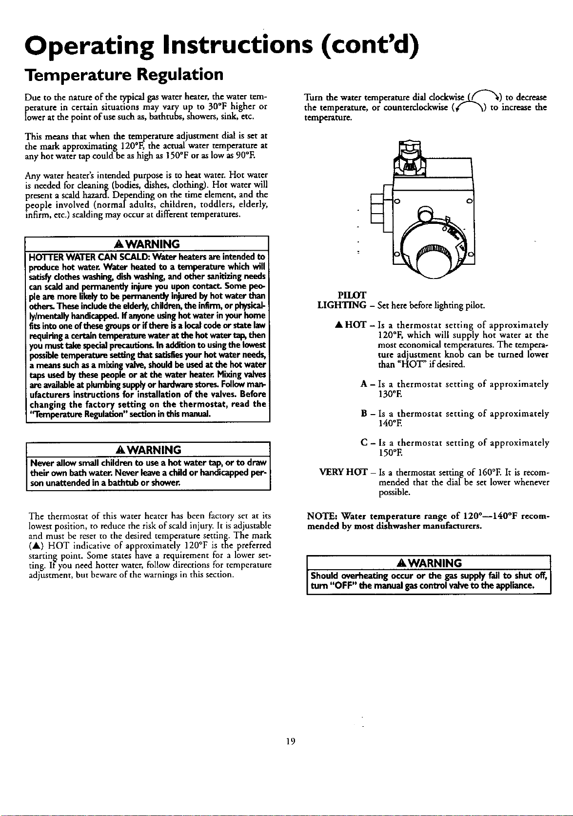
Turn the water temperature dial clockwiseLff'_) to decrease
the temperature, or counterclockwise (€" _) to increase the
temperature.
This means that when the temperature adjustment dial is set at
the mark approximating 120°F, the actualwater temperature at
any hot water tap could be as high as 150°F or as low as 90°E
Any water heaters intended purpose Is to heat water. Hot ware
is needed for cleaning (bodies, dishes, clothing). Hot water will
present ascald hazard. Dejpending on the time element, and the
people involved (normaladults, children, toddlers, elderly,
infirm, etc.) scalding may occur atdifferent temperatures.
AWARNING
HOTTERWATERCAN SCALD:Water heatersareintendedto
producehot water.Water heatedto a temperaturewhichwill
satisfyclotheswashing,dishwashing,and othersanitizingneeds
canscaldand permanentlyinjureyouuponcontact.Somepeo-
plearemorelikelyto bepermanentlyinjuredbyhotwaterthan
others.Theseincludetheelderly,children,theinfirm,orphysical-
lylmentallyhandicapped.If anyoneusinghotwater inyourhome
fitsintooneofthesegroupsor ifthere isa localcodeor statelaw
requiringacertaintemperaturewateratthe hotwater tap,then
you musttakespecialprecautions.Inadditionto usingthelowest
possibletemperaturesettingthatsatisfiesyour hotwater needs,
a meanssuchasa mixingvalve,shouldbe usedat the hotwater
tapsusedbythesepeopleor at the water heater.Mixingvalves
areavailableat plumbingsupplyor hardwarestore_Followman-
ufacturersinstructionsfor installationofthe valves.Before
changingthe factory setting on the thermostat, read the
"TemperatureRegulation"sectioninthis manual.
PILOT
LIGHTING - Set here before lighting pilot.
•HOT- Is athermostat setting of approximately
120°F, which will supply hot water at the
most economical temap,eratures.The tempera-
ture adjustment knob can be turned lower
than _HOT" if desired.
A - Is athermostat setting of approximately
130°E
B-Is athermostat setting of approximate|y
140°E
AWARNING
Neverallow smallchildrento usea hot watertap, or to draw
their own bathwater. Neverleavea childor handicappedper-
sonunattendedin abathtubor shower.
C - ls a thermostat setting of approximately
150°E
VERY HOT - Is a thermostat setting of 160°E It is recom-
mended that the dial be set lower whenever
possible.
The thermostat of this water heater has been factory set at its
lowest position, to reduce the risk of scald injury. It is adiustable
and must be reset to the desired temperature setting. The mark
(•) HOT indicative of approximately 120°F is the preferred
starting point. Some states have arequirement for alower set-
ting. If you need hotter water, follow directions for temperature
adjustment, but beware of the warnings in this section.
NOTE: Water temperature range of 120°--140°F recom-
mended by most dishwasher manufacturers.
AWARNING 1
Shouldoverheatingoccuror the gassupplyfail to shutoff,
Iturn "OFF" themanualgascontrolvalveto the appliance. I
19
Service and Adjustment
Tank (Sediment) Cleaning
Sediment build-up on the tank bottom may create varying
amounts of noise, and if left in the tank will cause premature
tank failure. In some water areas,you may not be able to drain
all sediment deposits by simply draining the tank. In these cases
Mag Erad (part no. 23600) can be used to help remove the sedi-
ment deposits. This may be ordered from theSears Service
Center. Forordering, refer to the _Parts Order List section.
Burner Inspection
AWARNING I
Do not .usethisapplianceifanypart of it.hL.sbeenunderwatt.
Immediately.call aSearsService Technictanto inspectthe
applianceand to replacethe gascontrolor any part of the
burnersystemwhichhasbeenunderwater.
Venting System Inspection
At least once ayear avisual inspection ihould be made of the
venting system. Youshould look for: .
•Obstructions which could cause improper venting. The com-
bustion and ventilation air flow must not be obstructed.
Damage or deterioration which could cause improper vent-
ing orleakage of combustion products.
Rusted flakesaround top of water heater.
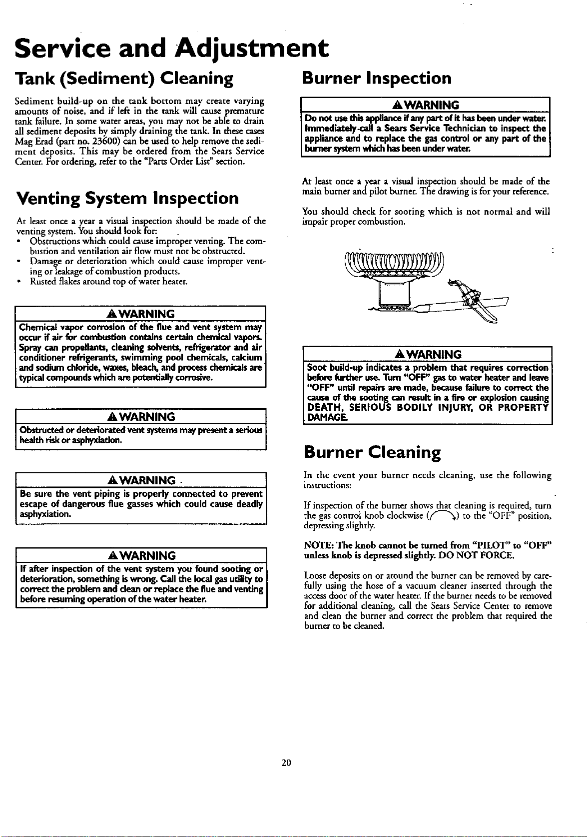
At least once ayear a visual inspection should be made of the
main burner andpilot burner. The drawing is for your reference.
You should check for sooting which is not normal and will
impair proper combustion.
_E,WARNING
Chemicalvapor corrosionof the flue andvent systemmay
occurif air for combustioncontainscertainchemicalvapors.
Spraycanpropellants,cleaningsolvents,refrigerator and air
conditionerrefrigerants, swimmingpoolchemicals,calcium
and sodiumchloride,waxes,bleach,and processchemicalsam
typicalcompoundswhichampotentiallycorrosive.
AWARNING
Obstructed or deterioratedventsystemsmaypresentaserious
healthrisk or asphyxiation.
IAWARNING ]
Be sure the vent pip_onnected to prevent|
escapeof dangerousflue gasseswhich could causedeadlyI
asphyxiation. J
AWARNING ]
If after inspectionof_you foundsooting or|
deterioration,something iswrong.Callthe localgasutilityto |
correctthe problemanddean or replacethe flueand venting|
beforeresuming operationofthe water heater. I
_,WARNING
Soot build-upindicatesaproblem that requirescorrection
beforefurtheruse.Turn'_FF" gasto water heaterandleave
"OFF" untilrepairsam made, becausefailureto correctthe
causeofthe sootingon resultin a fire or explosioncausing
DEATH, SERIOUS BODILY INJURY, OR PROPERTY
DAMAGE.
Burner Cleaning
In the event your burner needs cleaning, use the following
instructions:
If inspection of the burner shows that cleaning is required, turn
the gas control knob clockwise (ff"_) to the "OFF" position,
depressing slightly.
NOTE: The knob cannot be turned from PILOT' to OFF
unless knob is depressed sfighfly. DO NOT FORCE.
Loose deposits on or aroundthe burner can be removed by care-
fully using the hose of a vacuum cleaner inserted through the
accessdoor of the water heater. If the burner needs to be removed
for additional cleaning, call the Sears Service Center to remove
and clean the burner and correct the problem that required the
burner to be cleaned.
20
Service and Adjustment (cont'd)
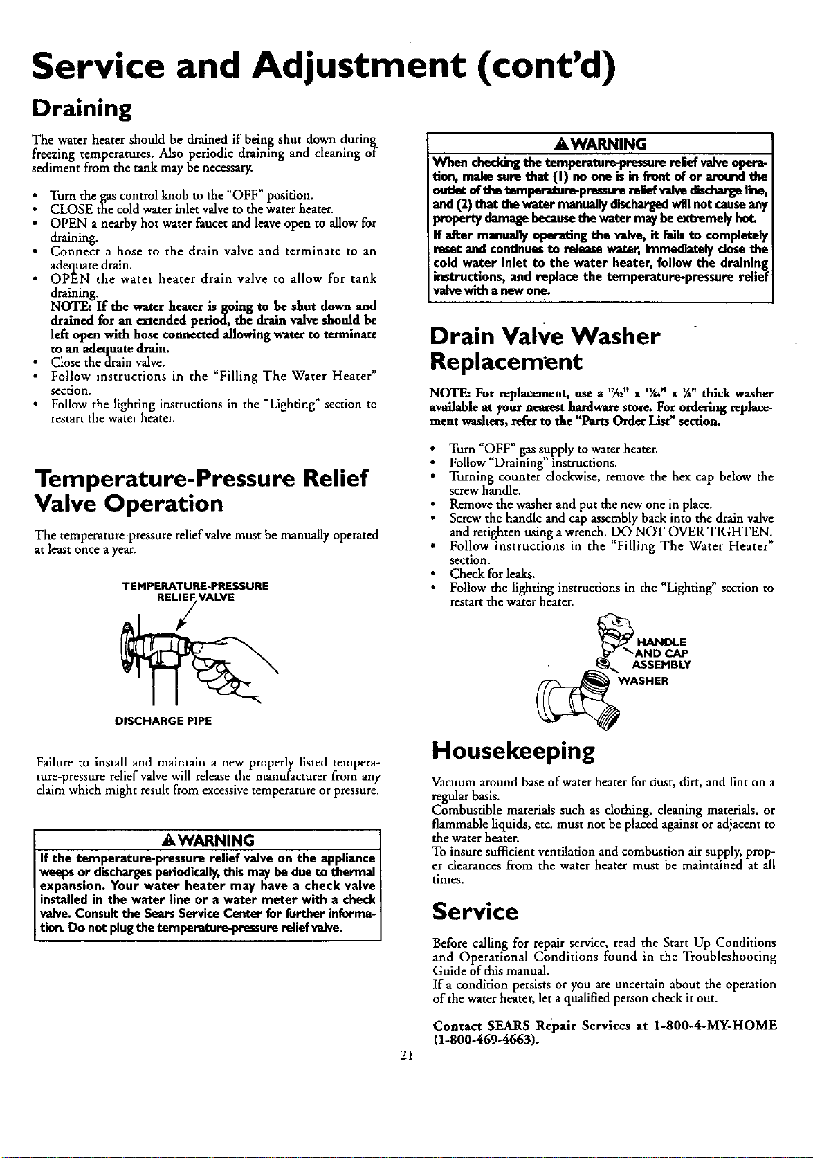
Draining
The water heater should be drained if being shut down during
freezing temperatures. Also periodic draining and cleaning of
sediment from the tank may be necessary.
Turn the gas control knob to the "OFF" position.
CLOSE the cold water inlet valveto the water heater.
•OPEN anearby hot water faucet and leave open to allow for
draining.
•Connect ahose to the drain valve and terminate to an
adequate drain.
• OPEN the water heater drain valve to allow for tank
draining.
NOTF_ If the water heater is going to be shut down and
drained for an extended period, the drain valve should be
left open with hose connected allowing water to terminate
to an adequate drain.
• Close thedrain valve.
•Follow instructions in the "Filling The Water Heater"
section.
• Follow the lighting instructions in the "Lighting" section to
restart the water heater.
_,WARNING
When checking the temperature-pressure relief valve opera_
tion, make sure that (I) no one is in front of or around the
outlet of the t_mperatu_-pressum relief valve discharge line,
and (2) that the water manually dischargedwill not cause any
property damage becansethe water may be extremely hot.
If after manually operating the valve, it fails to completely
reset and continues to release water, immediately closethe
cold water inlet to the water heater, follow the draining
instructions, and replace the temperature-pressure relief
valve with a new one.
Drain Valve Washer
Replacement
NOTE: For replacement, use a _%2"x:_'." x¼" thick washer
available at your nearest hardware store. For ordering replace-
ment washers, refer to the "Parts Order List" section.
Temperature-Pressure Relief
Valve Operation
The temperature-pressure relief valve must be manually operated
at least once a year.
TEMPERATURE-PRESSURE
REL; VALVE
Turn _OFF" gas supply to water heater.
Follow "Draining" instructions.
Turning counter clockwise, remove the hex cap below the
screw handle.
Remove the washer and put the new one in place.
Screw the handle and cap assembly back into the drain valve
and retighten using a wrench. DO NOT OVER TIGHTEN.
• Follow instructions in the "Filling The Water Heater"
section.
Check for leaks.
Follow the lighting instructions in the "Lighting" section to
restart the water heater.
"_AND CAP
ASSEMBLY
WASHER
DISCHARGE PIPE
Failure to install and maintain a new properly listed tempera-
ture-pressure relief valve will release the manufacturer from any
claim which might result from excessive temperature or pressure.
AWARNING
If the temperature-pressure relief valveon the appliance
weepsor dischargesperiodically,this may bedueto thermal
expansion. Your water heater may have a check valve
installedin the water line or a water meter with a check
valve.Consultthe SearsServiceCenter for further informa-
tion. Do not plugthe temperature-pressurerelief valve.
Housekeeping
Vacuum around base of water heater for dust, dirt, and lint on a
regular basis.
Combustible materials such as clothing, cleaning materials, or
flammable liquids, etc. must not be placed against or adjacent to
the water heater.
To insure sufficient ventilation and combustion air supply, prop-
er clearances from the water heater must be maintained at all
times.
Service
Before calling for repair service, read the Start Up Conditions
and Operational Conditions found in the Troubleshooting
Guide of this manual.
If acondition persists or you are uncertain about the operation
of the water heater, let a qualified person check it out.
Contact SEARS Repair Services at 1-800-4-MY-HOME
(1-800-469-4663).
21
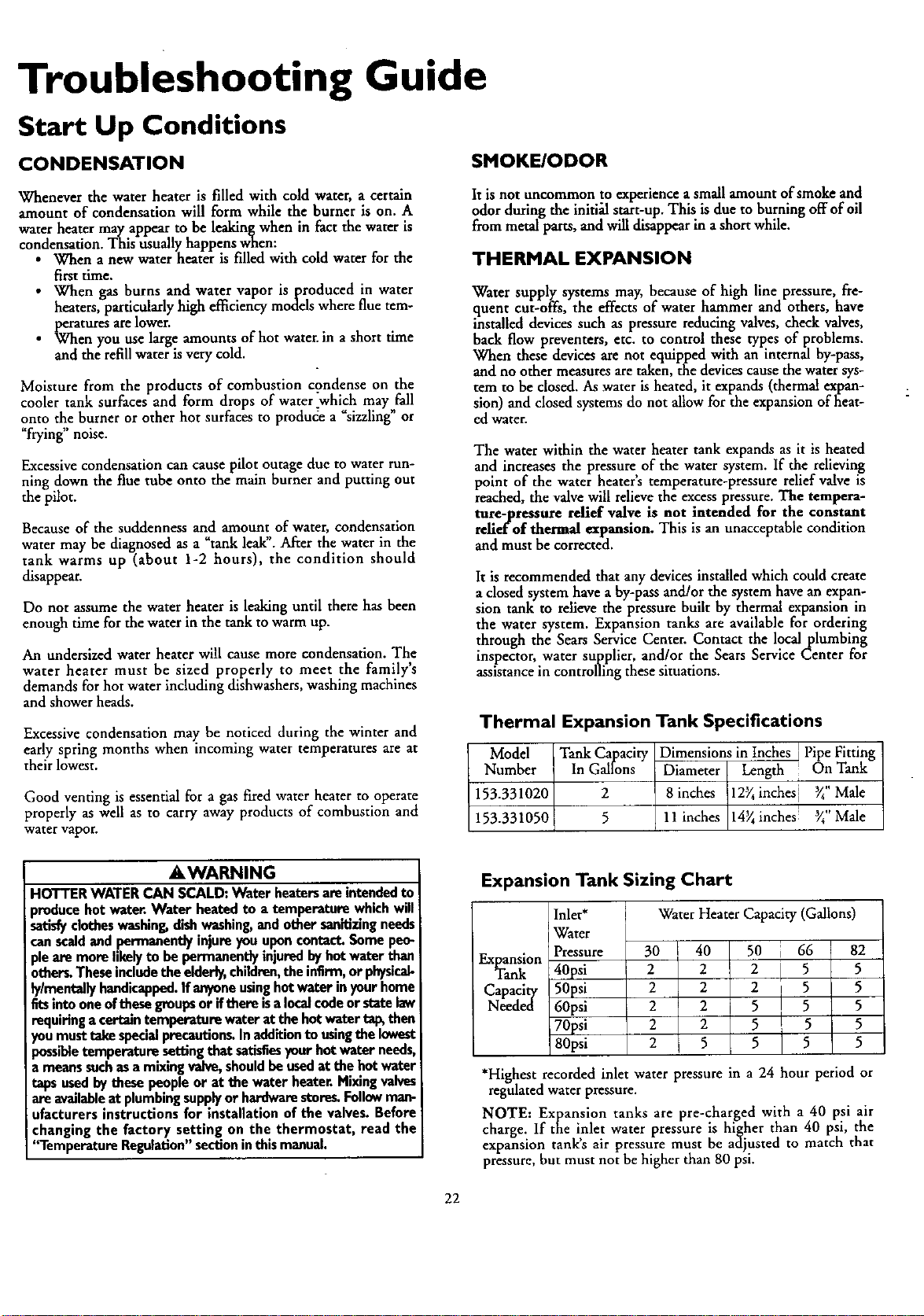
Troubleshooting Guide
Start Up Conditions
CONDENSATION
Whenever the water heater is filled with cold water, a certain
amount of condensation will form while the burner is on. A
water heater may appear to be leakin_when in fact the water is
condensation. This usually happens wnen:
•When anew water heater is filled with cold water for the
first time.
•When gas burns and water vapor is produced in water
heaters, particularly high efficiency models where flue tem-
peratures arelower.
When you use large amounts of hot water, in ashort time
and the refill water Isvery cold.
Moisture from the products of combustion condense on the
cooler tank surfaces and form drops of water ".which may fall
onto the burner or other hot surfaces to produde a "sizzling" or
"frying" noise.
Excessive condensation can cause pilot outage due to water run-
ning down the flue tube onto the main burner and putting out
the pilot.
Because of the suddenness and amount of water, condensation
water may be diagnosed as a"tank leak". After the water in the
tank warms up (about 1-2 hours), the condition should
disappear.
Do not assume the water heater is leaking until there has been
enough time for the water in the tank to warm up.
An undersized water heater will cause more condensation. The
water heater must be sized properly to meet the family's
demands for hot water including dishwashers, washing machines
and shower heads.
Excessive condensation may be noticed during the winter and
early spring months when incoming water temperatures are at
their lowest.
Good venting is essential for a gas fired water heater to operate
properly as well as to carry away products of combustion and
water vapor.
SMOKE/ODOR
It is not uncommon to experience asmall amount of smoke and
odor during the initi_ start-up. This is due to burning offof oil
from metal parts, and will disappear in ashort while.
THERMAL EXPANSION
Water supply systems may, because of high line pressure, fre-
quent cut-offs, the effects of water hammer and others, have
installed devices such as pressure reducing valves, check valves,
back flow preventers, etc. to control these types of problems.
When these devices are not equipped with an internal by-pass,
and no other measures are taken, the devices cause the water sys-
tem to be closed. As water is heated, it expands (thermal expan-
sion) and closed systems do not allow for the expansion of heat-
ed water.
The water within the water heater tank expands as it is heated
and increases the pressure of the water system. If the relieving
point of the water heater's remperature-pressure relief valve is
reached, the valve will relieve the excess pressure. The tempera-
ture-pressure relief valve is not intended for the constant
relief of thermal expansion. This is an unacceptable condition
and must be corrected.
It is recommended that any devices installed which could create
aclosed system have aby-pass and/or the system have an expan-
sion tank to relieve the pressure built by thermal expansion in
the water system. Expansion tanks are available for ordering
through the Sears Service Center. Contact the local plumbing
inspector, water supplier, and/or the Sears Service Center for
assistance in controlling these situations.
Thermal Expansion Tank Specifications
Model
Number Tank Capacity
In Gallons
2
5
153.331020
153.331050
Expansion Tank Sizing Chart
Water Heater Capacity (Gallons)
Dimensions in Inches I Pipe Fitting
Diameter Length : On Tank
8 inches 12_ inches] _" Male
i
llinches 14_inehes _"Male
AWARNING
HOTTERWATERCAN SCALD:Water heatersareintendedto
producehotwater.Water heatedto a temperaturewhichwill
satisfyclotheswashing,dishwashing,and othersanitizingneeds
canscaldandpermanentlyinjureyouuponcontact.Somepeo-
plearemorelikelyto bepermanentJyinjuredbyhotwaterthan
others,Theseincludetheelderly,children,the infirm,orphysicab
lylmentally handicapped.Ifanyoneusinghotwaterinyourhome
fitsintooneofthesegroupsor ifthere isalocalcodeor statelaw
requiringa certaintemperaturewaterat thehotwaterta_ then
you musttakespecialprecautions.Inadditionto usingthe lowest
mssibletemperature settingthat satisfiesyourhot water needs,
a meanssuchasa mixingvalve,shouldbeusedat the hotwater
tapsusedbythese people or at thewaterheater.Mixingvalves
areavailableat plumbingsupplyor hardwarestores.Followman-
ufacturersinstructionsfor installationof the valves.Before
changingthe factory setting on the thermostat, read the
'*l"emperotureRegulation"sectioninthis manual.
Expansion
Tank
Capacity
Needed
Inlet*
Water
Pressure 30 I 40 50
40psi 222
50psi 2 2 2
60psi 225
70psi 2 2 5
80psi 2 5 5
i66 82
5 5
5 5
5 5
5 5
5 5
*Highest recorded inlet water pressure in a24 hour period or
regulated water pressure.
NOTE: Expansion tanks are pre-charged with a 40 psi air
charge. If the inlet water pressure is higher than 40 psi, the
expansion tanks air pressure must be adjusted to match that
pressure, but must not be higher than 80 psi.
22
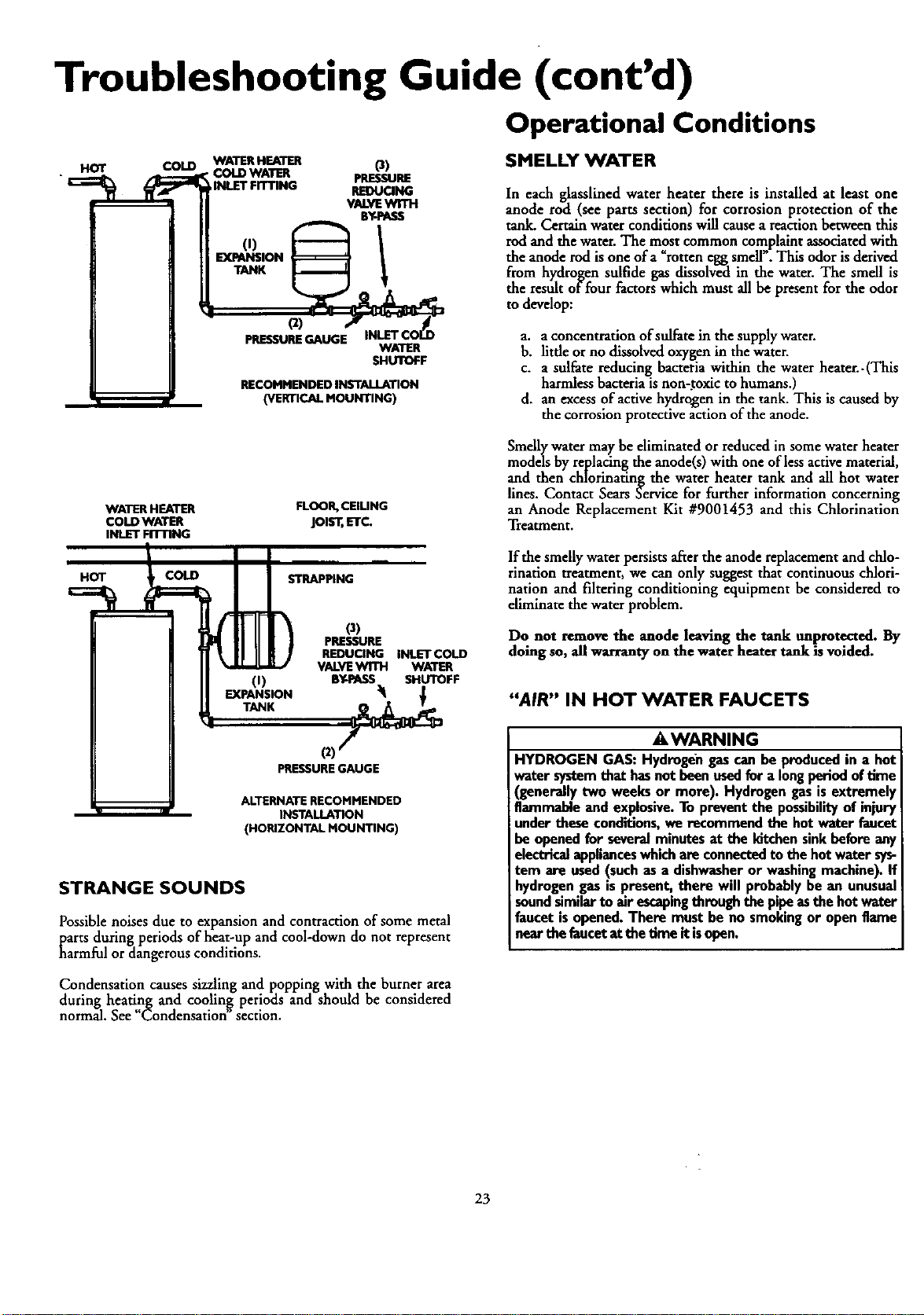
Troubleshooting Guide (cont'd)
Operational Conditions
HOT COLD WATE_HEAT_ O)
COLD WATER pRESSURE
INLET FITTING REDUCING
VALVE
BY-PASS
(t)
EXPANSION
TANK
_)
PRESSUREGAUGE INLET C
WATER
SHUTOFF
RECOMMENDED INSTALLATION
(VERTICAL MOUNTING)
SMELLY WATER
In each glasslined water heater there is installed at least one
anode rod (see parts section) for corrosion protection of the
tank. Certain water conditions will cause a reaction between this
rodand the water. The most common complaint assodated with
the anode rod is one of a rotten egg smell. This odor is derived
from hydrogen sulfide gas dissolved in the water. The smell is
the result offuur factors which must all be present for the odor
to develop:
a. aconcentration of sulfate in the supply warer.
b. little or no dissolved oxygen in the water.
c. a sulfate reducing bacteria within the water heater. -(This
harmless bacteria is non-.toxic to humans.)
d. an excess of active hydrogen in the tank. This is caused by
the corrosion protective action of the anode.
WATER HEATER
COLD WATER
INLET FITTING
HOT COLD
FLOOR,CEIUNG
JOLT,ETC.
STRAPPING
O)
EXIPANSION
o)
PRESSURE
REDUCING INLET COLD
VALVE WITH WATER
BY-PASS SHUTOFF
Smelly water may be eliminated or reduced in some water heater
models by replacing the anode(s) with one of less active material,
and then chlorinating the water heater tank and all hot water
lines. Contact Sears Service for further information concerning
an Anode Replacement Kit #9001453 and this Chlorination
Treatment.
lfthe smelly water persists after the anode replacement and chlo-
rinationtreatment, we can only suggest that continuous chlori-
nation and filtering conditioning equipment be considered to
eliminate the water pmblem.
Do not remove the anode leaving the tank unprotected. By
doing so, all warranty on the water heater tank is voided.
"AIR" IN HOT WATER FAUCETS
(2)
PRESSUREGAUGE
ALTERNATE RECOMMENDED
INSTALLATION
(HORIZONTAL MOUNTING)
STRANGE SOUNDS
Possible noises due to expansion and contraction of some metal
parts during periods of heat-up and cool-down do not represent
harmful or dangerous conditions.
AWARNING
HYDROGEN GAS: Hydrogen gas can be produced in a hot
water system that hasnot been used for a long period of time
(generally two weeks or more). Hydrogen gas is extremely
flammable and explosive. To prevent the possibilityof injury
under these conditions, we recommend the hot water faucet
be opened for several minutes at the kitchen sink before any
electrical applianceswhich are connected to the hot water sys-
tem are used (such as a dishwasher or washing machine). If
hydrogengasispresent, there will probablybe an unusual
soundsimilarto air escapingthrough the pipeasthe hotwater
faucet is opened. There must be no smoking or open flame
near the lancet at the time it isopen.
Condensation causes sizzling and popping with the burner area
during heating and coolin_ periods and should be considered
normal. See "Condensation section.
23
Troubleshooting Guide (cont'd)
Operational Conditions (cont'd)
HIGH TEMPERATURE SHUT OFF SYSTEM WATER IS TOO HOT
This water heater is equipped with an automatic gas shut offsys-
tem. The high temperature shut off is built into the gas control
valve. This system shuts off the gas supply to the water heater
burners when high water temperatures are present. It is non-
resetrable. If the high temperature shut off activates,the gascon-
trol valve must be replaced. If this were to occur,turn OFF the
entire gas supply to the water heater. Contact the Sears Service
Center.
I . _,WARNING
Shouldoverheatingoccur or the gassupplyfail to shut off,
turn "OFF" the manualgascontrolvalveto the appli_,ce.
NOT ENOUGH OR NO HOT WATER
•Check the manual gas shut offvalve to be sure it is open.
• Check the pilot flame. It may have gone out. All models have
an opening behind the outer door for viewing the pilot.
• If the pilot is not lit, follow the "Lighting" instructions in this
manual or located above the gas control valve on the water
heater to relight the pilot. If the water was extremely hot and is
now cold, the high limit safety temperature shut off may have
put out the burner and pilot. If the high temperature shut off
activates, the gas controlvalve must be replaced. Contact the
Sears Service Center.
•The gas control knob must be turned to the _ON" position.
•The temperature adjustment dial may be set too low. See the
'Temperature Regulat'on" section.
• The gas company can check the gas input to see if it is correct.
An underflred water heater will not heat water as quickly.
• Look for leaking or open hot water faucets. Make sure all are
closed.
• The cold water inlet temperature may be colder during the
winter months. It will take longer to heat the water and seem
like less hot water.
• The temperature adjustment.dial may be set too high. See the
"TemperatureAdjustment section.
NOTE: A period of time is necessary after an adjustment
has been made for the water temperature to reach the new
temperature setting.
• If lower temperature settings will not lower the water tempera-
ture, call the SearsService Center.
_,WARNING
Due to the nature of the typical gaswater heater, the
water temperature in certain situations may be hotter
than the thermostat setting.
Short, frequent drawsof hot water - especiallywith very
coldincomingwater - canshockthe thermostat into brief
operation resulting in hotter and hotter layers of water
closerto the top ofthe tank.
Changesin hot water usagepatterns or raising the tem-
perature differential between the cut-on of the thermo-
stat and the coldwater temperature will usuallyeliminate
the problem.
• If you cannot find what is wrong, call the Sears Service Center.
24
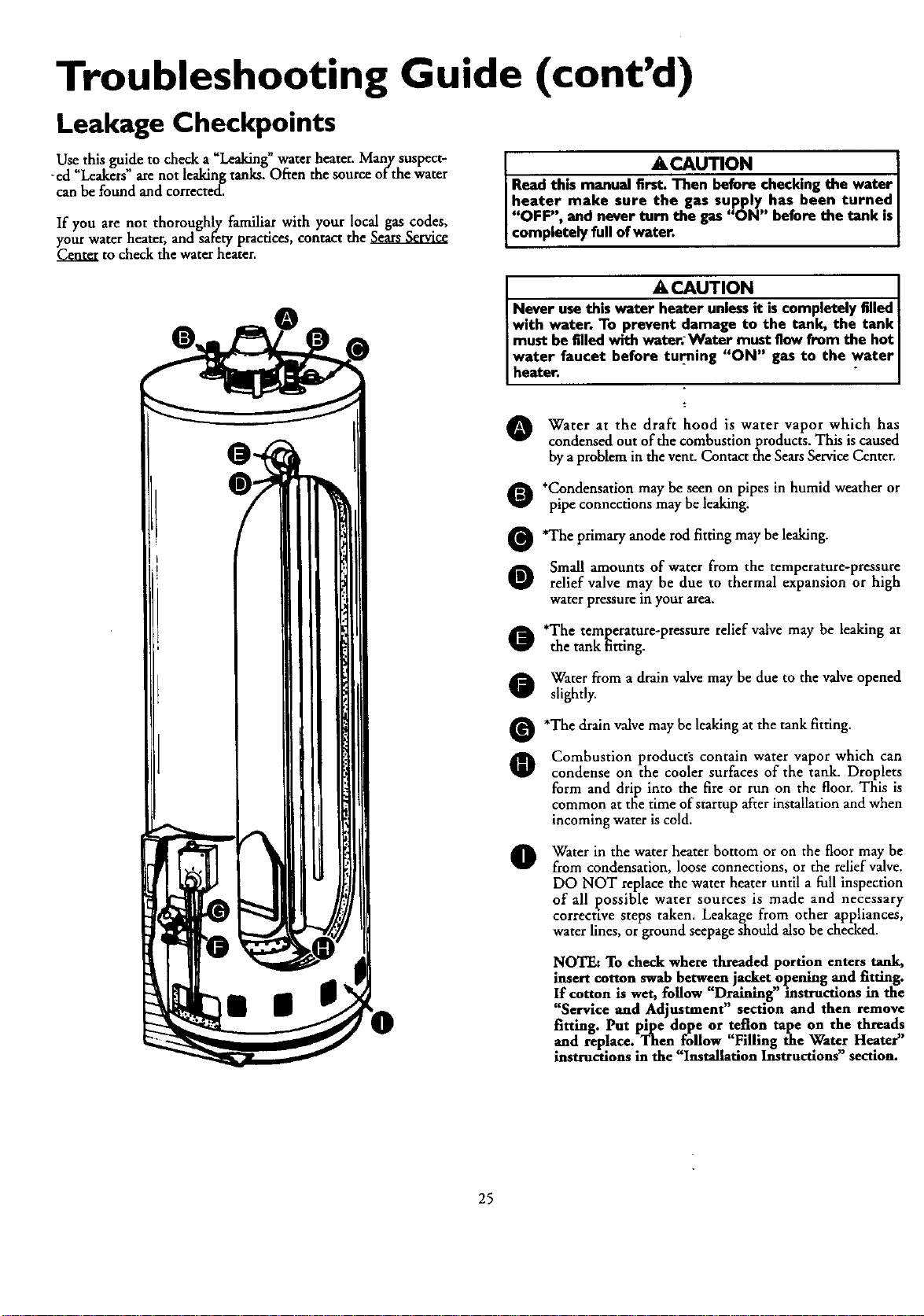
Troubleshooting Guide (cont'd)
Leakage Checkpoints
Use this guide to check a "Leaking"water heater. Many suspect-
-ed "Leakers" arenot leaking tanks. Often the source of the water
can be found and corrected.
If you are not thoroughly familiar with your local gas codes,
your water heater, and safety ptacdces, contact the
Center to check the water heater.
•_,CAUTION
Read this manual fi_ checkingthe water
heater make sure the gas supply has been turned
J"OFF", and never turn the gas"ON" before the tank isJ
Icompletely full ofwater. I
ACAUTION
N..ev.erusethis water heater unlessit iscompletely filled
with water. To prevent damage to the tank, the tank i
must befilled with water; Water must flow from the hot
water faucet before turning "ON" gas to the water
I heater" i " I
O Water at the draft hood is water vapor which has
condensed out of the combustion products. This is caused
by aproblem in the vent. Contact the SearsService Center.
O *Condensation may be seen on pipes in humid weather or
pipe connections may be leaking.
O'The primary anode rod fitting may be leaking.
O Small amounts of water from the temperature-pressure
relief valve may be due to thermal expansion or high
water pressure in your area,
o'The temperature-pressure relief valve may be leaking at
the tank fitting.
O Water from adrain valve may be due to the valve opened
slightly.
O'The drain valve may be leaking at the tank fitting.
O Combustion product_ contain water vapor which can
condense on the cooler surfaces of the tank. Droplets
form and drip into the fire or run on the floor. This is
common at the time ofstartup after installation and when
incoming water is cold.
OWater in the water heater bottom or on the floor may be
from condensation, loose connections, or the relief valve.
DO NOT replace the water beater until a full inspection
of all possible water sources is made and necessary
corrective steps taken. Leakage from other appliances,
water lines, or ground seepage should also be checked.
NOTE: To check where threaded portion enters tank,
insert cotton swab between jacket opening and fitting.
If cotton is wet, follow "Draining" instructions in the
"Service and Adjustment" section and then remove
fitting. Put pipe dope or teflon tape on the threads
and replace. Then follow "Filling the Water Heater"
instructions in the Installation Instructions section.
25
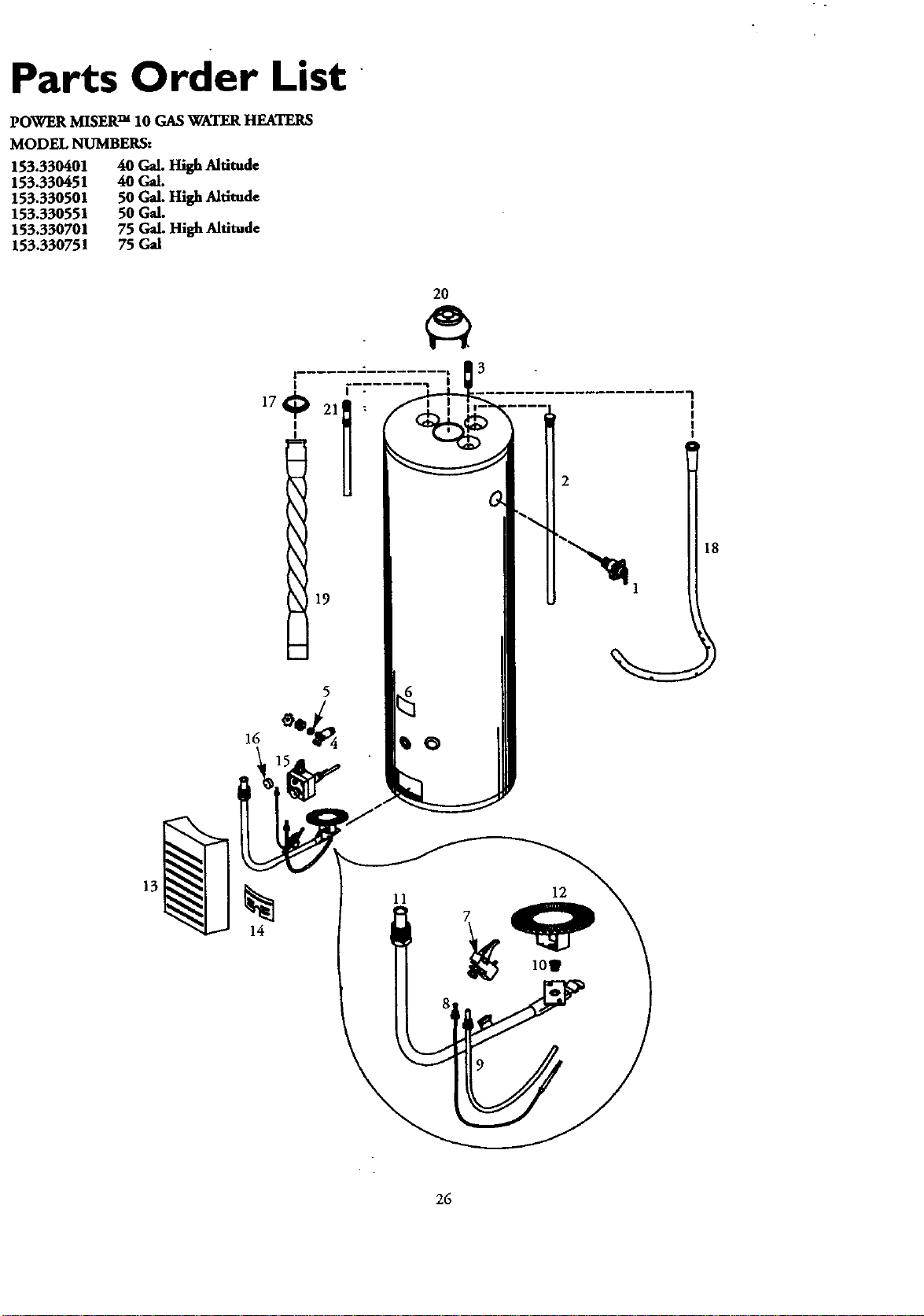
Parts Order List
POWER MISERTM 10 GAS WATER HEATERS
MODEL NUMBERS:
153.330401 40 Gal. High Altitude
153.330451 40 Gal.
153.330501 50 Gal. High Altitude
153.330551 50 Gal.
153.330701 75 Gal. High Altitude
153.330751 75 Gal
2O
19
18
14
26
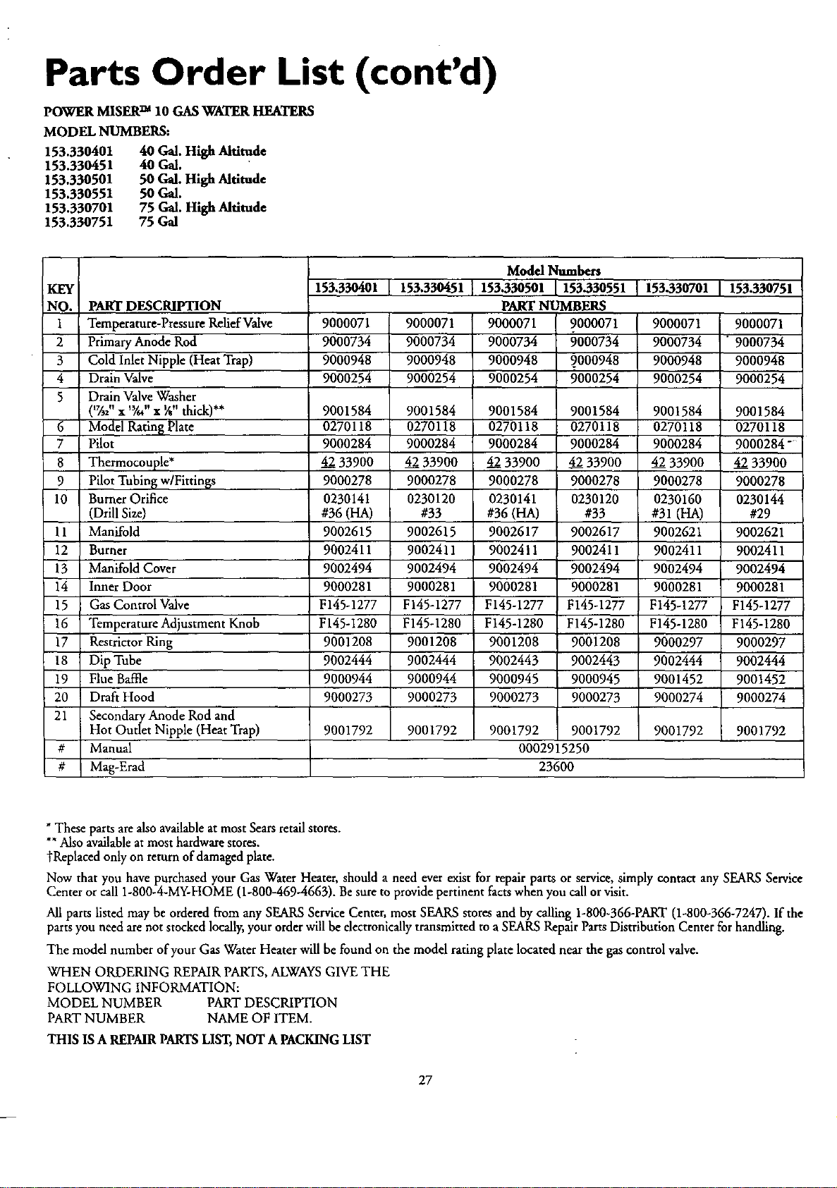
Parts Order List (cont'd)
POWER MISER TM 10 GAS_rATER HEATERS
MODEL NUMBERS:
153.330401 40 Gal. High Altitude
153.330451 40 Gal.
153.330501 50 Gal. High Altitude
153.330551 50 Gal.
153.330701 75 Gal. High Altitude
153.330751 75 Gal
KEY
NO.
1
2
3
4
5
153.330401 153.330451 153-330701 153-330751
PART DESCRIPTION
Temperature-Pressure Relief Valve 9000071 9000071 9000071 9000071
Primary Anode Rod 9000734 9000734 9000734 "9000734
Cold Inlet Nipple (Heat Trap) 9000948 9000948 9000948 9000948
Drain Valve 9000254 9000254 9000254 9000254
Drain Valve Washer
('%2" x 'Y." x ¼" thick)** 9001584 9001584 9001584 9001584
6Model Ratin_ Plate 0270118 0270118 0270118 0270118
7 Pilot 9000284 9000284 9000284 9000284"
8 Thermocouple* 42 33900 42 33900 42 33900 42 33900
9 Pilot Tubing w/Fitrings 9000278 9000278 9000278 9000278
10 Burner Orifice 0230141 0230120 0230160 0230144
(Drill Size) #36 (HA) #33 #31 (HA) #29
11 Manifold 9002615 9002615 9002621 9002621
12 Burner 9002411 9002411 9002411 9002411
13 Manifold Cover 9002494 9002494 9002494 9002494
14 Inner Door 9000281 9000281 9000281 9000281
15 Gas Control Valve F145-1277 F145-1277 F145-1277 F145-1277
16 Temperature Adjustment Knob F145-1280 F145-1280 F145-1280 F145-1280
17 Restrictor Ring 9001208 9001208 9000297 9000297
18 Dip Tube 9002444 9002444 9002444 9002444
19 Flue Baffle 9000944 9000944 9001452 9001452
20 Draft Hood 9000273 9000273 9000274 9000274
21 Secondary Anode Rod and
Hot Outlet Nipple (Heat Trap) 9001792 9001792 9001792 9001792
#Manual
#Mag-Erad
Model Numbers
153.330501 153-330551
PART NUMBERS
9000071 9000071
9000734 9000734
9000948 _000948
9000254 9000254
9001584 9001584
0270118 0270118
9000284 9000284
4233900 4233900
9000278 9000278
0230141 0230120
#36 (HA) #33
9002617 9002617
9002411 9002411
9002494 9002494
9000281 9000281
F145-1277 F145-1277
F145-1280 F145-1280
9001208 9001208
9002443 9002443
9000945 9000945
9000273 9000273
9001792 9001792
0002915250
23600
* These parts are also available at most Sears retail stores.
*" Also available at most hardware stores.
tReplaced only on return of damaged plate.
Now that you have purchased your Gas Water Heater, should aneed ever exist for repair parts or service, simply contact any SEARS Service
Center or call 1-800-4-MY-HOME (1-800-469-4663). Be sure to provide pertinent facts when you call or visit.
All parts listed may be ordered from any SEARS Service Center, most SEARS stores and by calling 1-800-366-PART (1-800-366-7247). If the
parts you need are not stocked locally, your order will be electronically transmitted to aSEARS Repair Parts Distribution Center for handling.
The model number of your Gas Water Heater will be found on the model rating plate located near the gas control valve.
WHEN ORDERING REPAIR PARTS, ALWAYS GIVE THE
FOLLOWING INFORMATION:
MODEL NUMBER PART DESCRIPTION
PART NUMBER NAME OF ITEM.
THIS IS AREPMR PARTS LIST, NOT A PACKING LIST
27
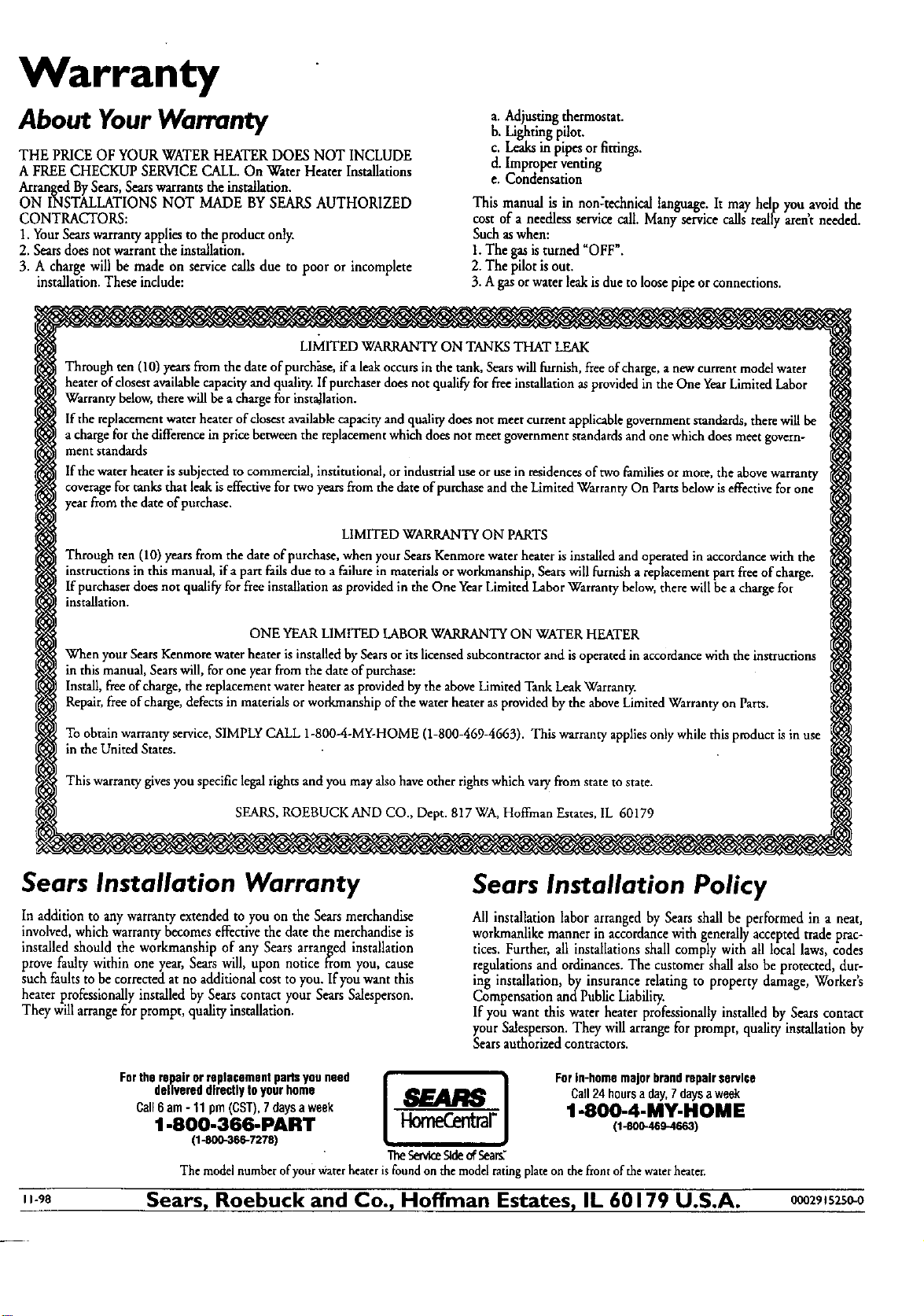
Warranty
About YourWarranty
THE PRICE OF YOUR WATERHEATER DOESNOT INCLUDE
A FREE CHECKUP SERVICECALL.On Water Heater Installations
ArrangedBySears,Searswarrantsthe installation.
ON INSTALLATIONS NOT MADE BYSEARS AUTHORIZED
CONTRACTORS:
1. YourSearswarrantyappliesto the product only.
2. Searsdoesnotwarrantthe installation.
3. A charge will be made on servicecallsdue to poor or incomplete
installation.Theseindude:
a. Adjustingthermostat.
b. Lightingpilot.
c. Leaksin pipesor fittings.
d. Improperventing
e. Condensation
This manual is in non:technical language.It may help youavoid the
cost of a needlessservicecall. Manyservicecallsreallyarentneeded.
Such aswhen:
1.The gasisturned "OFF".
2. The pilotis out.
3. Agasorwater leakisdue to loosepipe orconnections.
LIMITED WARRANTY ON TANKS THAT LEAK
Through ten (10) years from the date of purchase, ifa leak occursin the tank, Sears will furnish, free ofcharge,a new current model water
heater of closest availablecapacity and quality. If purchaser does not qualify for free installation as provided in the One Year Limited Labor
Warranty below, there x¢lllbe acharge for installation.
If the replacement water heater ofdosest availablecapacity and quality does not meet current applicablegovernment standards, there will be
acharge for the difference in price between the replacement which does not meet government standards andone which does meet govern-
ment standards
If the water heater is subjected to commercial, institutional, or industrialuse or use in residences of two families or more, the abovewarranty
coverage for tanks that leak is effective for two years from the date of purchase and the Limited Warranty On Parts below is effective for one
year from the date of purchase.
LIMITED WARRANTY ON PARTS
Through ten (10)yearsfrom thedate of purchase,when yourSearsKenmorewaterheateris installedand operatedin accordancewith the
instructionsin this manual,ifa part failsdueto a failurein materialsorworkmanship,Searswillfurnisha replacementpart freeofcharge.
If purchaserdoesnot qualifyfor freeinstallationasprovidedin the One YearLimitedLaborWarrantybelow,therewillbe a chargefor
installation.
ONE YEAR LIMITED LABOR WARRANTY ON WATER HEATER
Whenyour SearsKenmorewaterheareris installedbySearsor itslicensedsubcontractorand isoperatedin accordancewiththe instructions
in thismanual,Searswill, for oneyearfrom the dateof purchase:
Install,freeofcharge,the replacementwaterheaterasprovidedbytheaboveLimitedTankLeakWarranty.
Repair,freeofcharge,defectsin materialsorwod_nanshipofthe waterheaterasprovidedbythe aboveLimitedWarrantyonParts.
To obtain warranty service, SIMPLY CALL 1-800-4-MY-HOME (1-800-469-4663). This warranty appliesonly while this product is in use
in the United States.
This warranty givesyou specific legal rights and you may also have other rights which vary from state to state.
SEARS, ROEBUCK AND CO., Dept. 817 WA, Hoffman Estates, 1L 60179
Sears Installation Warranty
In addition to any warranty extended to you on the Sears merchandise
involved, which warranty becomes effective the date the merchandise is
installed should the workmanship of any Sears arranged installation
prove faulty within one year, Sears will, upon notice from you, cause
such faults to be corrected at no additional cost to you. If you want this
heater professionally installed by Sears contact your Sears Salesperson.
They will arrangefor prompt, quality installation.
Sears Installation Policy
All installation labor arrangedby Sears shall be performed in a neat,
workmanlike manner in accordance with generally accepted trade prac-
tices. Further, all installations shall comply with all local laws, codes
regulations and ordinances. The customer shall also be protected, dur-
ing installation, by insurance relating to property damage, Worker's
Compensation and Public Liability.
If you want this water heater professionally installed by Sears contact
your Salesperson. They will arrange for prompt, quality installation by
Sears authorized contractors.
I 1-98
Fortherepairorreplacementpaitsyouneed I _.ARS i Forin-homemajorbrandrepairservice
delivereddirectlytoyourhome Call24 hoursaday,7daysaweek
Call6am- 11prn(CST),7daysaweek '1-800-4-MY-HOME
1-800-366-PART (r-soo-4os-4ssa)
(1-800-366-7278) "iheServiceSldeofSea_
The model number of yourwater heateris found on themodel ratingplateon thefront of the waterheater.
Sears, Roebuck and Co., Hoffman Estates, IL 60179 U.S.A. 0002915250-0