Owners
Manual
FOR POTABLEWATER
HEATING ONLY
NOT SUITABLEFOR
SPACEHEATING
NOT FOR USE IN
MOBILE HOMES
Model No.
153.330401 40 Gal.HighAltitude
153.330451 40 Gal.
153.330501 50 Gal. HighAltitude
153.330551 50 Gal.
153.330701 75 Gal. HighAltitude
153.330751 75 Gal
Caution:
Read and Follow
All Safety Rules and
Operating Instructions
Before First Use of
This Product.
Savethis Manualfor FutureReference.
POWER MISER 12
GAS WATER HEATER
• Safety Instructions
•Installation
•Operation
For Your Safety
• Care and Maintenance
•Troubleshooting
• Parts List
AN ODORANT IS ADDED TO THE GAS USED BY THIS
WATER HEATER
WARNING: If the information in these instructions are not fol-
lowed exactly, a fire or explosion may result, causing property
damage, personal mlury or death.
-Do not store or use gasoline or other fl.am.mable vapors and liq-
uids in the vicinity of this or any other appliance.
-WHAT TO DO IF YOU SMELL GAS
•Do not try to light any appliance.
• Do not touch any electr,cal sw,tch; do not use any phone in your
building. . .
Immediately call your gas supplier from aneighbor's phone.
iFollow gassupplier_]nstructions.
the
If you can not reach your gassupplier, call the fire department.
-Insta..llation and service must be performed by a qualified installer,
serv,ce agency or the gassuppl,er.
*WARNING . I
Improper installation, adjus_on, service or maintenance |
can cause DEATH, SERIOUS BODILY INJURY, OR PROPERTY DAM- I
AGE. Refer to this manual for ass,stance or consult the local Sears I
iService Center or gas utility for further information. I
_oFAWARNING
lammable vapors may bed--_wn _y _rr currents from other areas
f the structure to this appliance.
I&WARNING
READ THE GENERAL SAFETY SECTION BEGINNING ON INSIDE
COVER AND THEN THIS ENTIRE MANUAL BEFORE INSTALLING
OR OPERATING THIS WATER HEATER.
Sears, Roebuck and Co., Hoffman Estates, IL 60179 U.S.A.
Safety Precautions
•,WARNING .I
Improper installation, adjustment, alteration, service
or maintenance can cause DEATH, SERIOUS BODILY I
INJURY,OR PROPERTY DAMAGE. Refer to this manu-
I al for assistance or consult your local Sears Service
LCenter for further nformat on.
AWARNING
WATER HEATERS EQUIPPED FOR ONE TYPE GAS
ONLY: This water heater is equipped for one type gas
only. Check the model rating plate near the gas control
valve for the correct gas. DO NOT USE THIS WATER
HEATER WITH ANY GAS OTHER THAN THE ONE
SHOWN ON THE MODEL RATING PLATE. Failure to
usathe correctgascancauseproblemswhichcanresultin
DEATH, SERIOUS BODILY INJURY, OR PROPERTY
DAMAGE. If you have any questions or doubts consult
yourgassupplieror localutility.
AWARNING
INSTALLATIONS IN AREAS WHERE FLAMMABLE LIQ-
UIDS (VAPORS) ARE LIKELY TO BE PRESENT OR
STORED (GARAGES, STORAGE, AND UTILITY AREAS
ETC): Flammable liquids (such as gasoline, solvents
propane(LP) or butane, etc.), allof whichemit flammabk
vapors, may be improperly stored or usedin suchareas.
The gaswater heater pilot lightor main burner canignite
such vapors. The resulting flashbackand fire can cause
death or seriousburns to anyone in the area, as well as
propertydamage.
If installation in suchareas isyour only option, then the
instaflatlonmust be accomplishedin away that the pilot
flame and main burner flame are elevated from the floor
at least 18 inches.While this may reducethe chancesof
flammablevaporsfrom a floor spillbeingignited,gasoline
and other flammable substancesshouldneverbe storedor
used in the same room or area containing a gas water
heater or other openflame or sparkproducingappliance.
NOTE: Flammable vaporsmay be drawn by air currents
from other areasof the structureto the appliance.
AWARNING
If this water heater will be usedin beauty shops,barber
shops,cleaning establishments,or self-servicelaundries
with dry cleaning equipment, it is imperative that the
water heater or water heaters be installedsothat com-
bustion and ventilation air be taken from outside these
areas. Refer to the "Facts to Consider About the
Location" sectionof this manual and also the latest edi-
tion of the National Fuel Gas Code, ANSI Z223.1, also
referred to as NFPA 54 for specificsprovidedconcerning
air required.
•,WARNING J
A fire canstart if combustiblemate.riaissuchas clothin_ I
deaning materials,or flammableIKimdsare placedagainst
or next tothe water heater.
AWARNING
At the time of manufacturethiswater heater was provid-
ed with a combination temperature-pressuresrelief valve
certified by a nationally recognized testing laboratory
that maintainsperiodic inspectionof productionof listed
equipment or materials,as meetingthe requirements for
ReliefValvesand Automatic GasShutoff Devicesfor Hot
Water Supply Systems,.andthe latest edition of ANSI
Z21.22 and the code requirements of ASME. If replaced,
the valvemust meet the requirements of localcodes, but
not lessthan a combination temperature and pressure
relief valve certified as meeting the requirements for
ReliefValvesand Automatic Gas Shutoff Devicesfor Hot
Water SupplySystems,ANSI Z21.22 by a nationallyrec-
ognized testing laboratory that maintains periodic
inspection of production of listed equipment or
materials.
The valvemust bemarked with a maximum set pressure
not to exceed the marked hydrostaticworking pressure
of the water heater (150 Ibs./sq. in.) and a discharge
capacity not less than the water heater input rate as
shown on the model rating plate. (Electric heaters -
watts dividedby 1000x 3415 equalBTU/Hr. rate.)
Your local jurisdictional authority, while mandating the
use of a temperature-pressure relief valve complying
with ANSI 2121.22and ASME, may require a valve model
different from the one furnishedwith the water heater.
Compliance with suchlocal requirements n_us_be satis-
fied by the installeror _nd 6sarJofthe Water heater with
a locally prescribed tempe_rat_re-pre_ur¢ relief valve
installedin the designatedo_eni_g in th_ w'4ter_eater in
placeof the fact°ry furnlshe_JValtve" |.!
For safe operation of tl_ev_ate_"heate_ th_ relief valve
must not be removed fron_ it'_ de_signlste#oRening or
plugged. I|!i | 1]
The temperature-press,lre _elie_ve _us_ belinstailed
directly intothe fitting ofthe wa_er I_eat_r&esi_ted for
the relief valve. Position_the_vai_ed_hvn_ar_an_ provide
tubingsothat anydisch_rge_villlex'_"_ml_wi_hinl6inches
above, or at any distancjeb_lov_th_r_ct_rai _oor. Be
certain that no contactlis n_ad_with_ahy I_ve_lectrical
part. The discharge op_eniogm.'ust_o_'be_blclcked or
reduced in size under lany_cir_:un_stahcet. E:_,essive
or useof moi_ than_fourelb"_e_vscan
length, over 30 feet,
cause restriction and reduce the_dlscharge_apac _of
the valve. _ _i _:
No valve or other obstru;'tion is to: be placed between
the relief valve and the tank. Do not connect_tubing
directly to discharge drain unless a 6" air gap is provided.
To prevent bodily injury, hazard to life, or property darn-
age, the relief valve must be allowed to discharge water
in quantities should circumstances demand. If the dis-
charge pipe is not connected to adrain or other suitable
means, the water flow may cause property damage.
The Discharge Pipe:
Must not be smaller in size than the outlet pipe size of
the valve, or have any reducing couplings or other
restrictions.
Must not be plugged or blocked.
Must be of material listed for hot water distribution.
Must be installed so as to ailow complete drainage of
both the temperature-pressure relief vaive, and the dis-
charge pipe.
Must terminate at an adequate drain.
•Must not have any valve between the relief valve and
tank.
Safety Precautions
&WARNING
A gaswater heater cannotoperate properly without the
correct amount of air for combustion.Do not installin a
confined area such a closet, unlessyou provide air as
shownin the "Facts to ConsiderAbout the Location" sec-
tion. Never obstruct the flow of ventilationair. if you have
any doubts or questions at all, call your gas company.
Failureto providethe proper amount of combustionair
can result in a fire or explosion and can cause DEATH,
lSERIOUSBODILY INJURY,OR PROPERTYDAMAGE.
&WARNING
This water heater must not be installeddirectly on car-
peting. Carpeting must be protected .bya metal or wood
panel beneath the appliance extendmg beyond the full
width and depth of the appliance by at least 3 inches
(76.2mm) in any direction, or if the appliance isinstalled
in an alcove or closet,the entire floor must hecoveredb
the panel. Failure to heed this warning may result in
fire hazard.
&WARNING
HOTTER WATER CAN SCALD: Water heaters are
intendedto produce hot water. Water heated to a tem-
perature whichwill satisfyclotheswashing,dishwashing,
.an.dother sanitizing needs can scald and permanently
injureyou uponcontact. Some people are more likelyto
be permanently injured by hut water than others. These
includethe elderly,children,the infirm, or physically/men-
tally handicapped.If anyoneusinghot water inyour home
fits into one of thesegroupsor if there isa localcode or
state lawrequiring a certaintemperature water at the hot
water ta_ then you musttake specialprecautions.In addi-
tion to usingthe lowestpossibletemperature setting that
satisfiesyour hot water needs,a means suchas a mixing
valve, shouldbe usedat the hot water taps usedbythese
people or at the water heater. Mixingvalvesare available
at plumbingsupplyor hardware stores.Follow manufac-
turers instructionsfor installation of the valves. Before
changingthe factory set_ng on the thermostat, read the
"Temperature Regulation"section in this manual.
&WARNING
Soot build-upindicates a problem that requires correc-
tion beforefurther use.Turn "OFF" gasto water heater
and leave "OFF" until repairs are made, becausefailure
to correct the causeof the sootingcan result in aEre or
explosion causing DEATH, SERIOUS BODILY INJURY,
OR PROPERTY DAMAGE.
&WARNING
VENT DAMPERS- Any vent damper,whether it isoperZ-
ed thermally or otherwise must be removed if its use
inhibitsproperdraftingofthe water heater.
Thermally Operated Vent Dampers: Gas-fired water
heaters havingthermal efficiency mexcessof 80% may
producea relatively low flue gastemperature. Such tem-
peratures may not be highenoughto properlyopenther_
maJlyoperated vent damper_ Thiswould causeSl).illageof
flue gasesandmay causecarbonmonoxidepeisonmg.
Vent dampersmust bear evidenceof certification ascom-
plying with the latest edition of American National
tandard ANSI Z21.68 (ANSI Z21.66 & 67, respectively,
cover electrically and mechanically actuated vent
dampers). Before installationof anyvent damper,consult
your local SearsService Center or the gasutility for fur-
ther information.
&WARNING
• The appliance and itsindividualshutoffvalvemustbedis-
connectedfrom the gassupplypipingsystemduring
pressuretesting of the gassystem at test pressuresm
excessof _poundper squareinch(3.SkPa).
*The appliance must be isolatedfrom the gassupplypip-
ing systemby closingits individualmanualshutoffvalve
during anypressuretestingof the gassupplypipingsys-
tem at test pressuresequal or lessthan '/2pound per
square inch(3.5kPa).
AWARNING
BEFORE LIGHTING [PROPANE (L.P.) GAS WATER
HEATERS]: Propane (L.R) gasis heavierthan air. Should
there be aleak in the system,the gaswill settle near the
ground. Basements, crawl spaces, skirted areas under
mobile homes (even when ventilated), closetsand areas
belowgroundlevelwill serve aspocketsfor the accumula-
tion of this gas.Before attempting to light or relight the
water heater's pilot or turning on a nearby electricallight
switch,he absolutelysure there isno accumulatedgasin
the area. Search for odor of gasby sniffingat groundlevel
in the vicinity of the appliance. If odor is detected,follow
stepsindicatedat "For YourSafety" on the cover pageof
this manualthen leavethe premises.
&WARNING
Chemical vapor corrosion of the flue and vent system
may occurif air for combustioncontainscertain chemical
vapors.Spraycanpropellants,cleaningsolvents,refrigera-
tor and air conditioner refrigerants, swimming pool
chemicals,calcium and sodium chloride, waxes, bleach,
and processchemicalsare typical compoundswhich are
potentiallycorrosive.
&WARNING
Obstructed or deteriorated vent systemsmay present a
serious healthrisk or asphyxiation.
3
Safety Precautions continued on page 4
Safety Precautions
r AWARNING I
I The water heater with draft hood installed must be prep- |
Jerly vented to a chimney which terminates outdoors. I
I Never operate the water heater unless it ts vented to the I
I ontdoors and h.asadequate air supply to avoid risks of I
I improper operation, explosion or asphyxiation. I
_,WARNING
Minimum clearancesbetween the water heater and com-
bustibleconstructionare I" at the sidesand rear,4" at the
front, and 6" from the vent pipe. Clearance from the top
of the jacket is 18" on most models. Note that a lesser
dimensionmay be allowedon some models Refer to the
labelon the water heater adjacentto the gascontrolvalve
for all clearances.
ACAUTION
WATER HEATERS EVENTUALLY LEAK: Installation of
the water heater must be accomplished in such a manner
that if the tank or any connections should leak, the flow of
water will not cause damage to the structure. When such
locations cannot be avoided, a suitable drain pan should
be installed under the water heater. Drain pans am wail.
able at your local Sears store. Such adrain pan must be
not greater than I_ inches deep, have aminimum length
and width of at least 2 inches greater than the water
heater dimensions and must be piped to an adequate
drain. The pan must not restrict combustion air flow.
Under no circumstances is the manufacturer or Sears to
be held liable for any water damage in connection with
this water heater.
IAWARNING J
Do not use this appliance if any part of it has been under I
water. Immediately call aSears Service Technician to I
inspect the appliance and to replace the gas control or any
part of the bemer system which hasbeen under water.
AWARNING
HYDROGEN GAS: Hydrogen gascan be produced in a hot
water system that has not been used for a long period of
time (generally two weeks or more). Hydrogen gas is
extremely flammable and explosive. To prevent the possi-
bility of injury under these conditions, we recommend the
hot water faucet be opened for several minutes at the
kitchen sink before any electrical appliances which are
connected to the hot water system are used (such asadis-
hwasher or washing machine). If hydrogen gas !s present,
there will probably be an unusual sound similar to air
escaping through the pipe as the hot water faucet is
opened. There must be no smoldng or open flame near
the faucet at the time it isopen.
AWARNING
INSULATING JACKETS: When installing an external
water heater insulation jacket on a gas water heater:
DO NOT cover the temperature-pressure relief valve.
DO NOT put insulation over any part of the top of the
gaswater heater.
DO NOT put insulation over the gas control valve or gas
control valve/burner cover, or any access areas to the
burner.
DO NOT let insulation around the gas water heater to
get within 8 inches of the floor (air must get to the
burner).
DO NOT cover or remove operating Instructions, and
safety related warning labels and materials affixed to the
water heater.
_aJlureto head this will result in the possibility of a fire or
explosion.
Table of Contents
Safety Precautions ............................................................................................................................................24
Table of Contents ................................................................................................................................................5
Customer Responsibilities .......................................................................................................................6
Product Specincations'_"..................................................................................................................................6
Materials and Basic Tools Needed ...............................................................................................7
MaterialsNeeded ................................................................................................... .................................................................... 7
BasicTools................................................................................................................................................................................ 7
Installation Instructions ........................................................................................................................s-16
Removing the Old Water Heater ............................................................................................................................................... 8
Facts to Consider About the Locadon....................................................................................................................................... 9
Combustion Air andVentilation for Appliances in Unconfined Spaces ................................................................................... 10
Combustion Air andVentilation for Appliances in Confined Spaces....................................................................................... 10
Water Piping ........................................................................................................................................................................... 11
Temperature-Pressure ReliefValve........................................................................................................................................... 12
Filling the Water Heater .......................................................................................................................................................... 13
Venting .............................................................................................................................................................................. 13-14
14 15
Gas Piping ......................................................................................................................................................................... -
Installation Checklist .............................................................................................................................................................. 16
"""uperatlngInstructions .........................................................................................................................17-19
l_k tin "_ 17-18
gh g ............ ..**. ...................... *.**.** ..................... ...... ....................... ....... .......................... •.................... .......................
Temperature Regulation.......................................................................................................................................................... 19
Service and Adjustment ......................................................................................................................20-22
Tank (Sediment) Cleaning ...................................................................................................................................................... 20
Venting System Inspection ...................................................................................................................................................... 20
Burner Inspection ................................................................................................................................................................... 20
Burner Cleaning ..................................................................................................................................................................... 20
Draining ............................................................................................................................................................. :................... 21
Temperature-Pressure ReliefValveOperation .......................................................................................................................... 21
Drain ValveWasher Replacement ........................................................................................................................................... 21
Housekeeping ......................................................................................................................................................................... 21
Service .................................................................................................................................................................................... 21
Troubleshooting Guide ........................................................................................................................22-25
Start Up Conditions ............................................................................................................................................................... 22
Condensation ....................................................................................................................................................................... 22
Smoke/Odor ......................................................................................................................................................................... 22
Thermal Expansion ......................................................................................................................................................... 22-23
Strange Sounds ..................................................................................................................................................................... 23
Operational Conditions ..................................................................................................................................................... 23-24
SmellyWater ......................................................................................................................................................................... 23
"Air" in Hot Water Faucets................................................................................................................................................... 23
High Temperature Shut OffSystem ...................................................................................................................................... 24
Not Enough Hot Water ........................................................................................................................................................ 24
Water is too Hot ................................................................................................................................................................... 24
LeakageCheckpoints .............................................................................................................................................................. 25
Parts Order List...............................................................................................................................................26-27
Customer Responsibilities
Thank You for purchasinga Sears water heater. °
Properly installed and maintained, it should give you years of
trou'blefree service. If you should decide that you want the new
water heater professionally installed by Sears call the local Sears
Service Center or any Sears store. They will arrange for prompt,
quality installation by Sears authorized contractors.
Abbreviations Found In This Instruction Manual
A.G.A. - American Gas Association o
A.N.S.I. - American National Standards Institute
N.EP.A. - National Fire Protection Agency
AWARNING
This gas-firod water beater is design certified by the
American Gas AssociationLaboratories under American
National Standards for GasWater Heaters. The installa-
tion mustconformwith this manual,LocalCodes andwith
the latest edition of the National Fuel Gas Code, ANSI
/.223.1.
Thispublicationisavailablefrom yourlocalg.ove,rnment or
public library, gas company, or by wr,tmg NFPA,
BatterymarchPark, Quincy,MA 02269.
•Read the "Safety Precautions" section, pages 2 through 4 of
this manual first and then the entire manual carefully. If you
don't follow the safety rules, the water heater will not operate
properly. It could cause DEATH, SERIOUS BODILY
INJURY AND/OR PROPERTYDAMAGE.
This manual contains instructionsfor the installation, opera-
tion, and maintenance of the gas-fired water heater. It also
contains warnings through out the manual that you must read
and be aware of. Allwarnings and all instructions are essential
to the proper operation of the water heater and your safety.
Since we cannot put everything on the first fewpages, READ
THE ENTIRE MANUAL BEFORE ATTEMPTING TO
INSTALL OR OPERATE THE WATERHEATER.
The installation must conform with the instructions in this
manual; gas company rules; and Local Codes, or in the
absence of LocalCodes, with the latestedition of the National
Fuel Gas code, ANSI Z223.1, also referredto as NFPA 54.
This publication is availablefrom your local government or
public library or gas company or by writing NFPA,
Batterymarch Park,Quincy,/viA 02269.
Ifafter readingthis manual you have any questions or do not
understand any portion of the instructions, call the Sears
ServiceCenter.
Carefillly plan the placewhere you aregoing to put the water
heater. Correct combustion, vent action, and vent pipe instal-
lation arevery important in preventing death from possible
carbon monoxide poisoning and fires.
Examine the location to ensure the waterhea_r complies with
the _Facts to Consider about the Location section in this
manual.
For California installation this water heatermust be braced,
anchored, or strapped to avoid falling or moving during an
earthquake. See instructions for correct installation proce-
dures. Instructions may be obtained from your local dealer,
wholesaler, public utilities or California Office of the State
Architect, 400 PStreet, Sacramento, CA 95814.
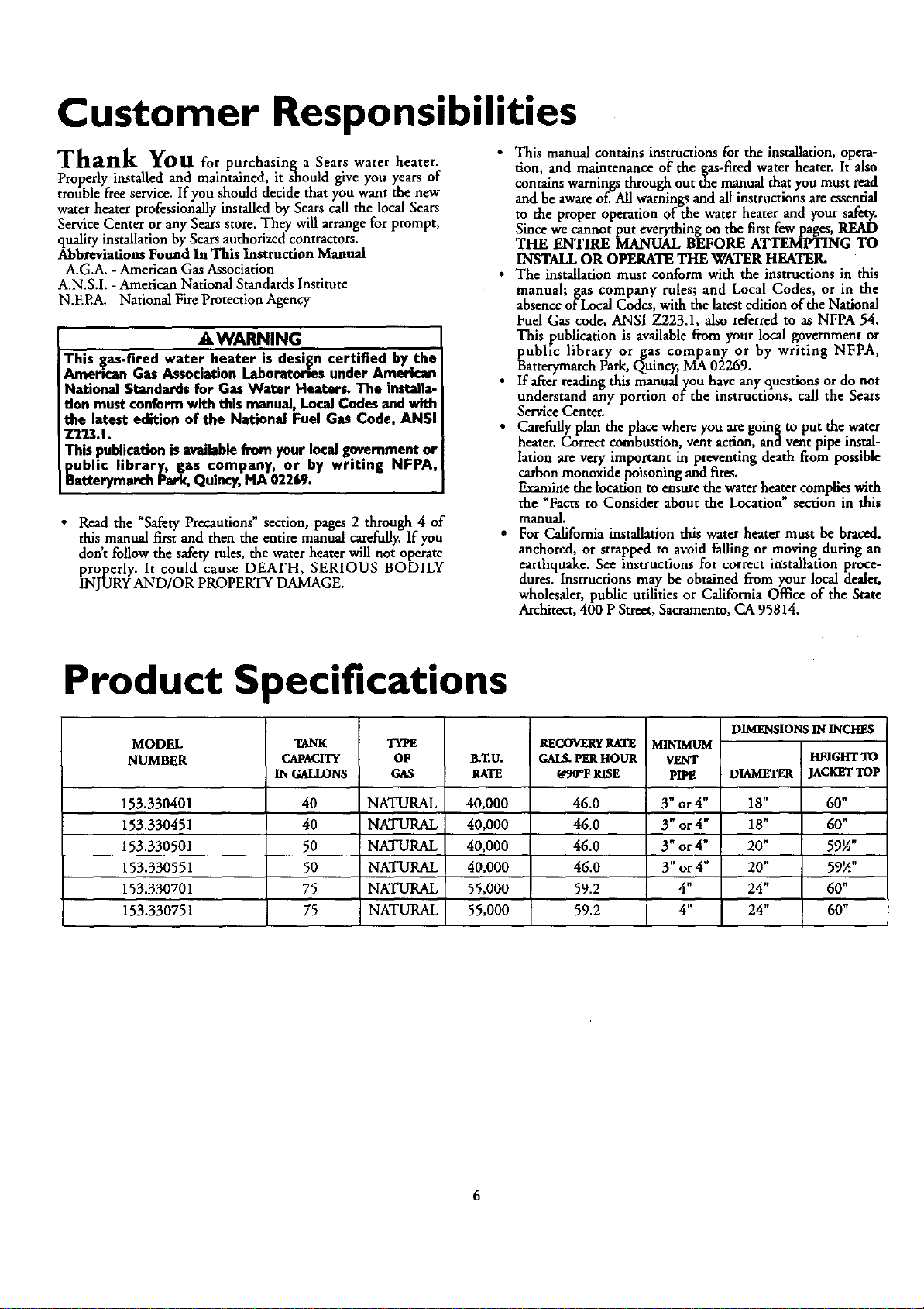
Product Specifications
MODEL
NUMBER TANK
CAPACITY
IN GALLONS
TYPE
OF
GAS gT.U.
RATE
RECOVERy RA1_
GAI_ PER HOUR
OgO'F RISE
153.330401 40 NATURAL 40,000 46.0
153.330451 40 NATURAL 40,000 46.0
153.330501 50 NATURAL 40,000 46.0
153.330551 50 NATURAL 40,000 46.0
153.330701 75 NATURAL 55,000 59.2
153.330751 75 NATURAL 55,000 59.2
MINIMUM
VENT
PIPE
3" or4"
3" or4"
3" or 4"
3" or4"
4"
4"
DIMENSIONS IN INCHES
HEIGHTTO
DIAMETER JACKETTOP
18" 60"
18" 60"
20" 59½"
20" 59½"
24" 60"
24" 60"
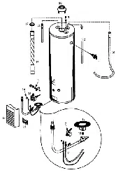
Materials and Basic Tools Needed
Materials Needed
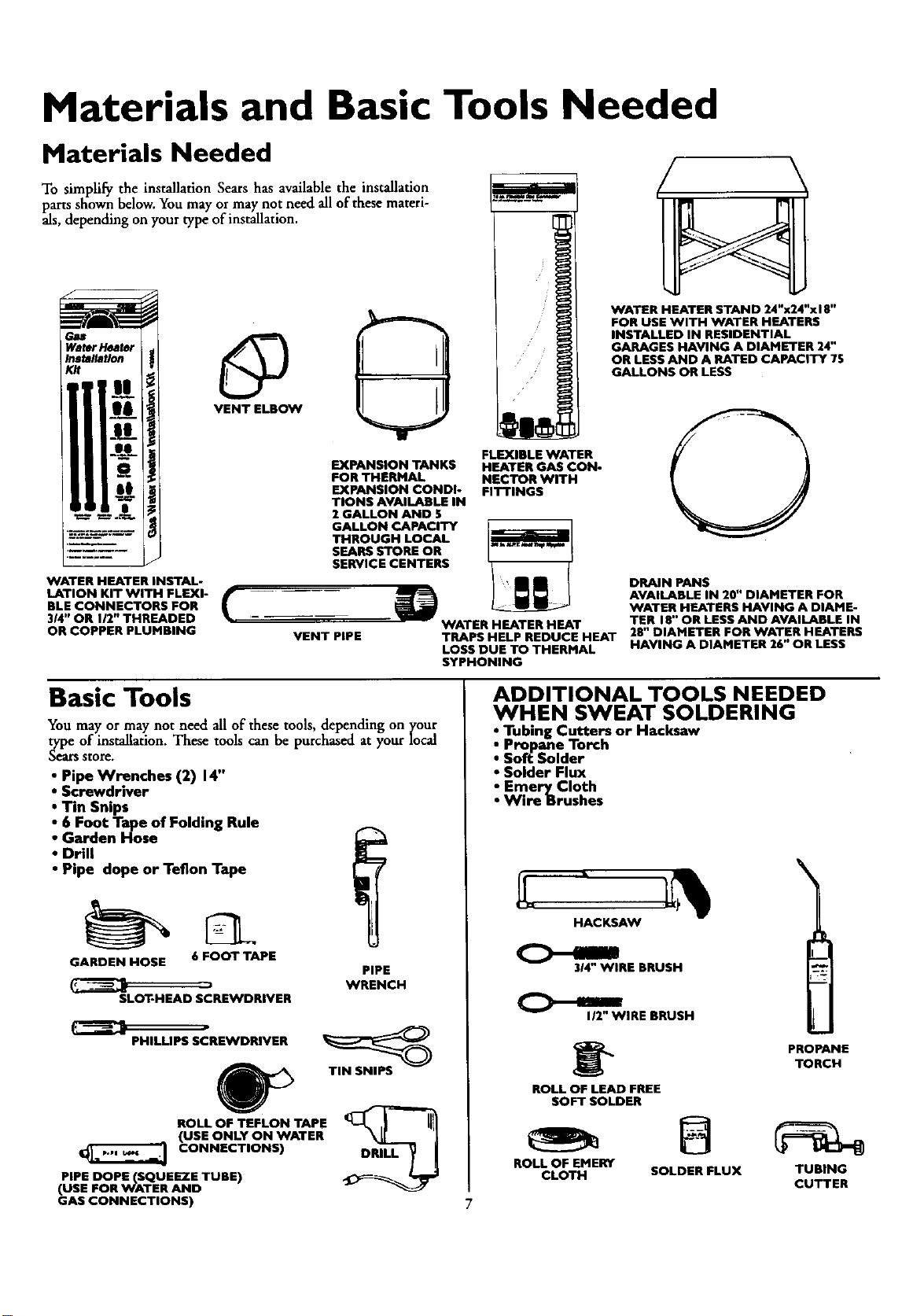
To simplify the installation Sears has available the installation
parts shown below. You may or may not need all of these materi-
als, depending on your type of installation.
WATER HEATER INSTAL-
LATION KIT WITH FLEXI-
BLE CONNECTORS FOR
314"OR 112"THREADED
OR COPPER PLUMBING
VENT ELBOW
EXPANSION TANKS
FOR THERMAL
EXPANSION CONDI-
TIONS AVAILABLE IN
2 GALLON AND 5
GALLON CAPACITY
THROUGH LOCAL
SEARS STORE OR
SERVICE CENTERS
WATER HEATER STAND 24"x24"xl 8"
FOR USE WITH WATER HEATERS
INSTALLED IN RESIDENTIAL
GARAGES HAVING A DIAMETER 24"
OR LESS AND A RATED CAPACITY 75
GALLONS OR LESS
FLEXIBLE WATER
HEATER GAS CON-
NECTOR WITH
FITTINGS
VENT PIPE
DRAIN PANS
AVAILABLE IN 20" DIAMETER FOR
WATER HEATERS HAVING A DIAME-
WATER HEATER HEAT TER 18" OR LESS AND AVAILABLE IN
TRAPS HELP REDUCE HEAT 28" DIAMETER FOR WATER HEATERS
LOSS DUE TO THERMAL HAVING A DIAMETER 26" OR LESS
SYPHONING
Basic Tools
You may or may not need all of these tools, depending on your
type of installation. These tools can be purchased at your local
S_at_ StOl_.
• Pipe Wrenches (2) 14"
•Screwdriver
• Tin Snips
•6 Foot Tape of Folding Rule
•Garden Hose
•Drill
•Pipe dope or Teflon Tape
GARDEN HOSE 6 FOOT TAPE
SLOT-HEAD SCREWDRIVER
PIPE
WRENCH
PHILLIPS SCREWDRIVER
ROLL OF TEFLON TAPE
(USE ONLY ON WATER
CONNECTIONS)
PIPE DOPE(SQUEEZE TUBE)
(USE FOR WATER AND
GAS CONNECTIONS)
TIN SNIPS
DRILL
ADDITIONAL TOOLS NEEDED
WHEN SWEAT SOLDERING
•Tubing Cutters or Hacksaw
• Propane Torch
•So_ Solder
•Solder Flux
• Emery Cloth
•Wire Brushes
7
HACKSAW
_RE BRUSH
__1J2' WIRE BRUSH
PROPANE
TORCH
ROLL OF LEAD FREE
SOFT SOLDER
ROLL OF EMERY
CLOTH SOLDER FLUX TUBING
CUTTER
Installation Instructions
Removing the Old Water Heater
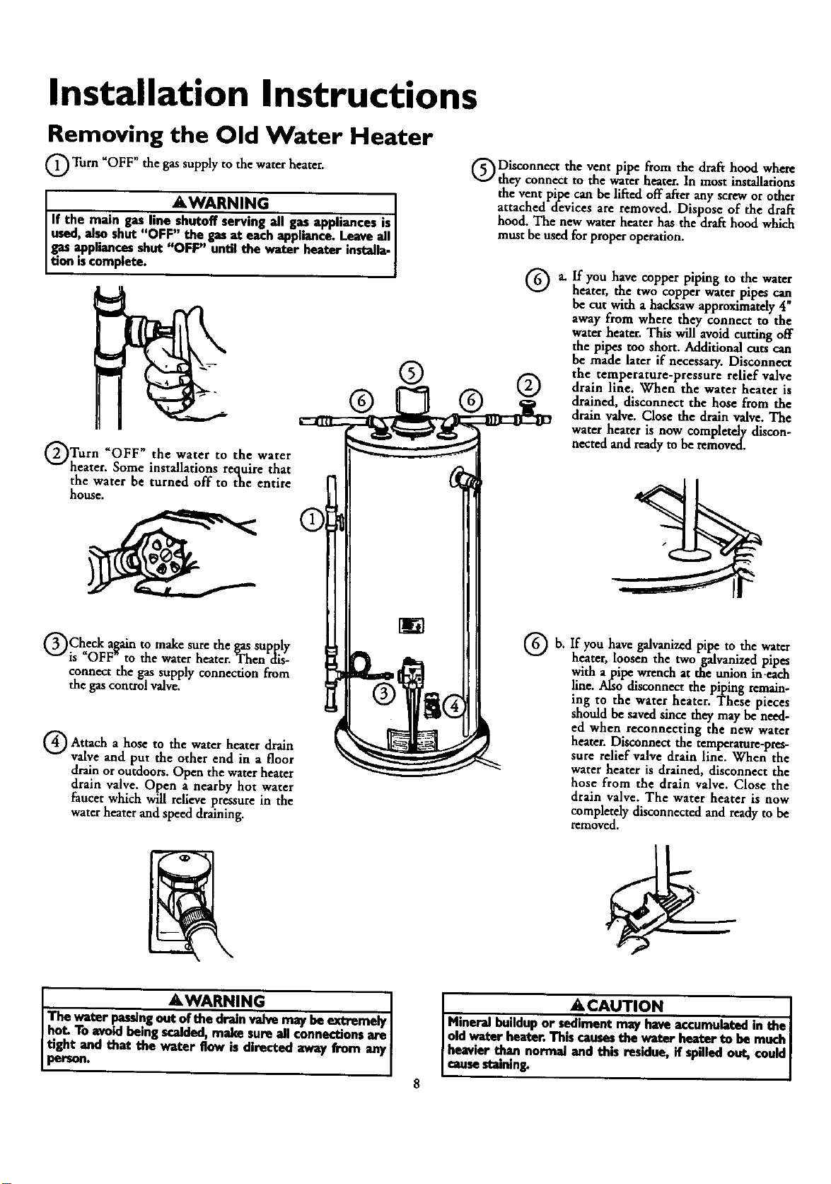
Q Turn _OFF" the gassupply to the water heater.
AWARNING
I If the main gasline shutoff serving all gas appliances is
[ used,alsoshut "OFF" the gasat eachappliance.Leaveall [
Jgas Pppliancasshut "OFF" until the water heater installa.J
Jtion iscomplete.
QTurn "OFF" the water to the water
heater. Some installations require that
the water be turned off to the entire
house.
QCheck a_ain to make sure the gassupply
is OFF to the water heater. Then dis-
connect the gas supply connection from
the gascontrol valve.
Q Attach hose the heater drain
ato water
valve and put the other end in a floor
drainor outdoors. Open the waterheater
drain valve. Open a nearby hot water
faucet which will relieve pressure in the
water heater and speed draining.
O Disconnect the vent pipe from the draft hood where
th_ connect to the water heater. In most instalhtiom
the vent pipe can be lifted off after any screw or other
attached devices are removed. Dispose of the draft
hood. The new water heater has the draft hood which
must be used for proper operation.
®
Qb.
If you have copper piping to the water
heater, the two €opper water pipes can
be cut with a hacksaw approximately 4"
away from where they connect to the
water heater. This will avoid cutting off
the pipes too short. Additional cuts can
be made later if necessary. Disconnect
the temperature-pressure relief valve
drain line. When the water heater is
drained, disconnect the hose from the
drain valve. Close the drain valve. The
water heater is now completely discon-
nected and ready to be removed.
If you have galvanizedpipe to the water
heater, loosen the two galvanized pipes
with a pipe wrench at the union in.each
line. Also disconnect the piping remain-
ing to the water heater. These pieces
sh6uld be saved since they may be need-
ed when reconnecting the new water
heater. Disconnect the remperamre-pres-
sure relief valve drain line. When the
water heater is drained, disconnect the
hose from the drain valve. Close the
drain valve. The water heater is now
completely disconnectedand readyto be
removed.
AWARNING 1
The water pas_ng out of the drain valve may be extremely I
hot. To avoid being scalded, ma_'..esure all connections are |
tight and that the wuter flow _directed away from any
person. [
•&CAUTION
[ Mineral buildupor..s_,dlmeutmay haveaccumulatedin the
[ oldwater heater.Thtscausesthe water hea_r to be much
] heavierthan normal and this residue,if spilledout, could
[ causestaining.
Installation Instructions (cont'd)
Facts to Consider About the
Location
You should carefully choose an indoor location for the new
water heater, because the placement is a very important consid-
eration for the safety of the occupants in the buildin_and for
the most economical use of the appliance. This waterneaser is
not fi_r use in mobile homes or outdoor installation.
Whether replacing an old water heater or putting the water
hearer in a new location, the following critical points must be
observed.
•The location selected should be indoors as close as practical
to the gas vent or chimney to which the water heater vent is
going to be connected, and as centralized with the water pip-
ing system as possible. The water heater, as all water heaters,
will eventually leak. Do not install without adequate
drainage provisions where water flow will cause damage.
ACAUTION
WATER HEATERSEVENTUALLY LEAK:Installationofthe
water heatermustbe accomplished in suchamannerthat if
the tankor awtconnectionsshouldleak,theglowof waterwill
net causedamageto the st_.uctore.When suchIocatiomcan-
notbe avoided,a suitabledrainpanshouldbe installedunder
the water heater.Drainpansareavailableat yourlocalSears
store.Suchadrain panmustbe not greaterthan 1½inches
deep,havea minimumlengthandwidthof at least2 inches
greaterthanthe water heaterdimensionsandmustbepiped
toanadequatedrai_ Thepanmustnotrestrictcombustionair
flow.Underno circumstancesisthe manufactureror Searsto
be heldliablefor anywater damagein connectionwith this
waterheat_.
AWARNING
INSTALLATIONSIN AREASWHERE FLAMMABLEUQUIDS
(VAPORS) ARE LIKELY TO BE PRESENT OR STORED
GARAGES, STORAGE, AND UTILITY AREAS, ETC):
Flammableliquids(suchas gasoline,solvents,propane(LP) or
butane, etc.), all of whichemit flammable vapors,may be
improperlysterador asadin sucharem,The gaswater heator
p,ot lightor mainburnercanignitesuchvaper_The resulting
flashbackand timcancausedeathor seriousbumsto anyonem
thearea,aswellaspmpertydamage.
If installationin suchareasisyouronlyop_or_thentheinstalla-
tion mustbeaccomplishedin a waythat the pilot flame and
mainbumerflameareelevatedfromtheflooratleast18 inche_
While thismayreducethechancesof flammablevaporsfrom a
flour spillbeingignited,gasolineandotherflamm_e substances
shouldneverbe storedor usedin the sameroomor areacon-
tainingagaswatt" beat_"or otheropenflameor sperkproduc-
ingappliance.
NOTF_Flammablevaporsmay be drawnbyair currentsfrom
otherareasof thestructomto theappliance.
AWARNING
Propellantsof _ spraysand volatilecompounds,(dean-
ers,chlorinebasedchemicals,refrigerants,etc.)inadditionto
being highlyflammablein many cases,will alsochangeto cor-
resive hydrochloricacid when exposedto the combustion
p_ducts ofthe water heater.The resultscanbe hazerdom
andalsocauseproductfailure.
•The location selection must provide adequate clearances for ser-
vicing and proper operation of the waterheater.
AWARNING
This waterheatermustnot be installeddirectlyon carpetin&
Carpeting must be protected by ametal or wood panel
beneath the applianceextendingbeyondthe fullwidth and
depthof the appliancebyat least3 inches(76.2mm) in an)
direction,o¢if theapplianceisinstalledin analcoveor closet
the entirefloormustbe coveredby thepaneLFailureto heec
thiswarningmayresoltina gm haca_l.
AWARNING
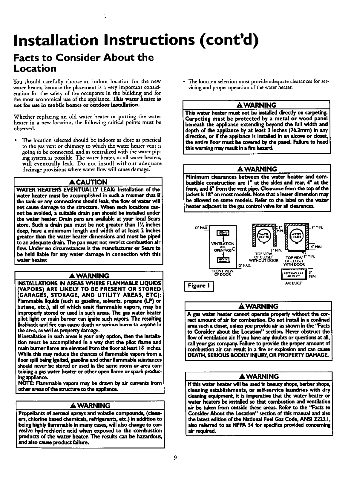
Minimum clearancesbetween the water heater and com-
bustibleconstructionare I" at shesidesand rear,4" at the
freot,and6"fremtheventpipe.Clearancefremthetop ofthe
jacketis18"en mostmodek Notetbeta lesserdimemienmay
be allowedon somemodel_Referto the labelonthe water
heateradjacentto thegascoutrolvaivefor ail dearancus.
tr_
t
VENTILATION
AIR
OPENINGS O
FRONT vIEW
OF DOOR
Figure I I
%111 ii
TOP VIE'_ =
OF CLOSET TOP VI E',N 1" I"llN.
W1THOUT DOOR OF CLO3ET
_" MAX, "W1TH DOO_
- I- To.
AIR DUCT
AWARNING
Agnswaterheatorcmmotaperate properlywithouttl_ cot-
amountof air forcombustio_Do not installin a confined
areasucha dosot,unlessyouprovideair asshowninthe"Facts
to Consideraboutthe Location"section.Neverobstructthe
flow ofventgadonair.ifyou haveanydoubtsorquestionsat all,
callyour gascompany.Failureto providethe properamountof
combustionair canresult in a fire or explosionandcancause
DEATH,SERIOUSBODILYINJUR_,ORPROPERTYDAMAGE
AWARNING
Ifthlswaterbeaterwill be usedin beautyshops,barbershops,
cleaningestablishments,or self-servicelaundrieswith dry
cleaningequipment, it isimperativethat the waterheateror
water heatersbe installedsothat combustionandventilation
air be takenfrom outside theseaseas.Referte the "Facts to
ConsiderAboutthe Location"sectionof this man,_l andalso
thelatesteditionoftbe NationalFuelGasCode,ANSI7.223.1,
alsoreferredto asNFPA54 for specificsprovidedconcerning
air required.
Installation Instructions (cont'd)
Combustion Air and Ventilation
for Appliances Located in
Unconfined Spaces
Unconfined Space is aspace whose volume is not less than 50
cubic feet per 1,000 Btu per hour of the aggregate input rating
of all appliances installed in that space. Rooms communicating
directly with the space in which the appliances are installed,
through openings not furnished with doors, are considered a
part of the unconfined space
In unconfined spaces in buildings, infiltration may be adequate
to provide air for combustion, ventilation and dilution of flue
gases. However, in buildings of tight construction (for example,
weather stripping, heavily insulated, caulked, vapor barrier, etc.),
additional air may need to be provided using the methods
described in Combustion Air and Ventilation for Appliances
Located in Confined Spaces, b.
Combustion Air and Ventilation
for Appliances Located in
Confined Spaces
Comqned Space is a space whose volume is less than 50 cubic
fdet per 1,000 Btu per hour of the aggregate input ratingof all
appliances installed in that space.
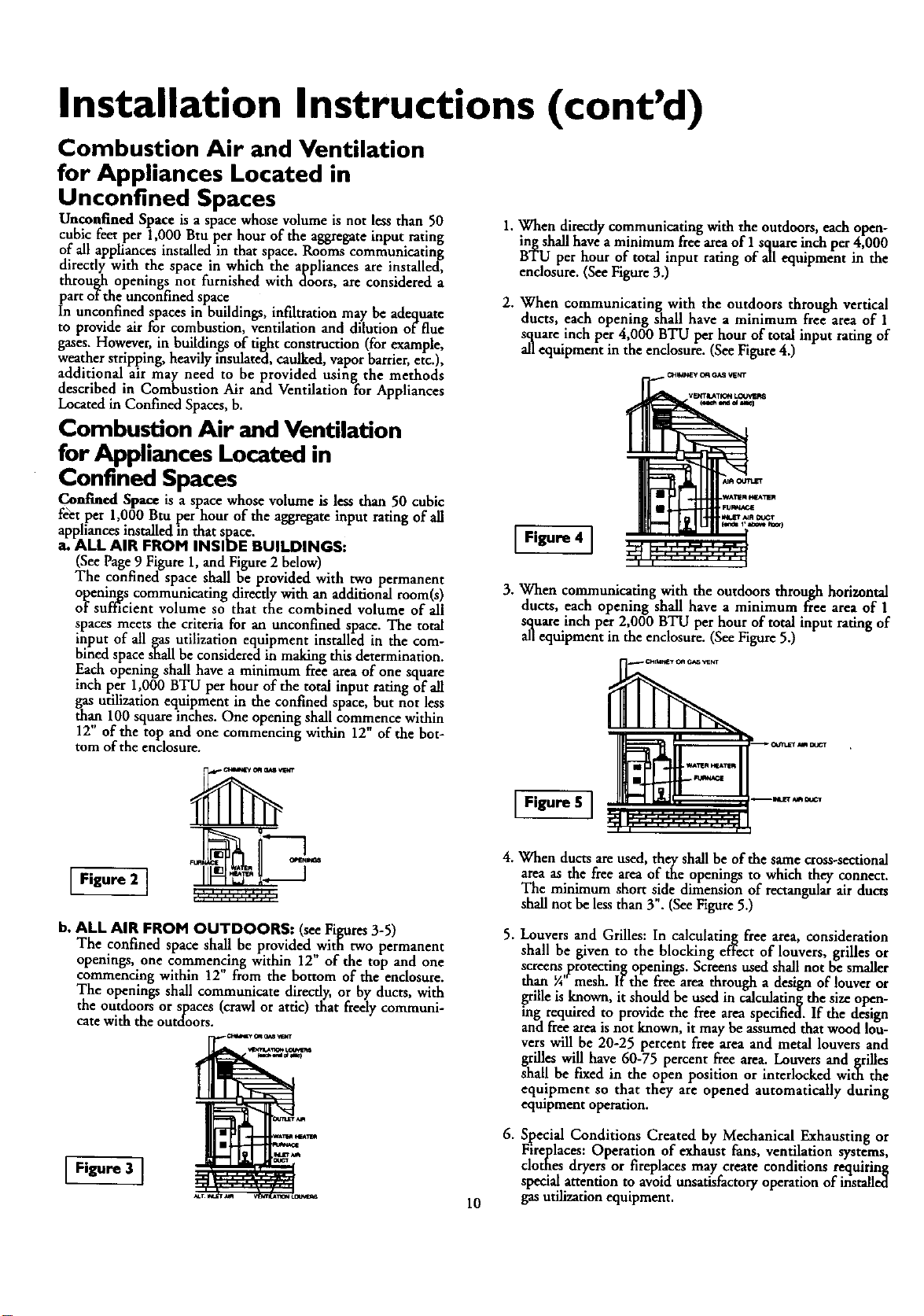
a. ALL AIR FROM INSIDE BUILDINGS:
(See Page9 Figure 1,and Figure2 below)
The confined space shall be provided with two permanent
openings communicating directly with an additional room(s)
of sufficient volume so that the combined volume of all
spaces meets the criteria for an unconfined space. The total
input of all gas utilization equipment installed in the com-
bined space shall be considered in making this determination.
Each opening shall have a minimum free area of one square
inch per 1,000 BTU per hour of the total input rating of all
gas utilization equipment in the confined space, but not less
than 100 square inches. One opening shall commence within
12" of the top and one commencing within 12" of the bot-
tom of the enclosure.
Figure 2 ]
b. ALL AIR FROM OUTDOORS: (seeFigures_3-5)
The confined space shall be providedwitfi two permanent
openings, one commencing within 12 of the top and one
commencing within 12" from the bottom of the enclosure.
The openings shall communicate directly, or by ducts, with
the outdoors or spaces (crawl or attic) that freely communi-
cate with the outdoors.
1. When direcdy communicating with the outdoors, each open-
ing shall have a minimum free a_'ea of I square inch per 4,000
BTU per hour of total input rating of all equipment in the
enclosure. (See Figure 3.)
2. When communicating with the outdoors through vertical
ducts, each opening shall have a minimum free area of 1
square inch per 4,000 BTU per hour of total input rating of
all equipment in the enclosure. (See Figure 4.)
Figure 4 ]
10
3. When communicating with the outdoors through horizontal
ducts, each opening shall have a minimum free area of 1
square inch per 2,000 BTU per hour of total input rating of
all equipment in the enclosure. (See Figure 5.)
TM
I I .... i roll II
4. When ducts are used, they shall be of the same cross-sectional
area as the free area of the openings to which they connect.
The minimum short side dimension of rectangularair ducts
shall not be lessthan 3". (See Figure5.)
5. Louvers and Grilles: In calculating free area, consideration
shall be given to the blocking effect of louvers, grilles or
screens protecting openings. Screens used shall not be smaller
than ¼"mesh. If the free area through adesign of louver or
grille is known, it should be used in calculating the size open-
ing required to provide the free area specified. If the design
and free area is not known, it may be assumed that wood lou-
vers will be 20-25 percent free area and metal louvers and
grilles will have 60-75 percent free area. Louvers and grilles
shall be fixed in the open position or interlocked with the
equipment so that they are opened automatically during
eqmpment operation.
6. Special Conditions Created by Mechanical Exhausting or
Fireplaces: Operation of exhaust fans, ventilation systems,
clothes dryers or fireplaces may create conditions requiting
special attention to avoid unsatisfactory operation of installed
gas utilization equipment.
Installation Instructions (cont'd)
Water Piping
AWARNING
HOTTERWATERCAN SCAL_.Water heate_areintendedto
Psatlroducehot vr_en.Water heatedto a temperaturewhichwill
slyclotheswashing+dishwashing+andothersanitizingneeds
canscaldand permanentlyinjureyouuponcontact.Somepeo-
plearemorelikelyto bepermanentlyinjuredbyhotwaterthan
othermTheseindudetheelderlt4children,theinfirm,or ph_€_
ly/mentaJlyhandicapped,Ifanyoneusinghotwaterinyourhome
fitsintooneofthesegroupsor ifthereisa Ioca]codeorslaiteI_v
requiringacertaintemperaturewaterat thehotwater_than
youmusttakespecialprecaulion_In additionto usingthelowest
possibletemperaturesettingthatsatisfiesyourhot waterneeds,
a meanssuchesa mixing valve,shouldbeusedat thehotwater
teps us.ed,bythesepeopleor at the waterbeatenMixing valves
areawlableatplumbingsupplyor hardwarestoremFollowman-
ufacturersinstructionsfor installationofthe valves.Before
changingthe factory settingon the thermostat, read the
'+TemperatureRegulation"sectioninthismanual
This water heater shall not be connectedto any heating systems or
component(s) used with a non-potablewater heating appliance.
If a water heater is installed in a closed water supply system;
such as one having a back-flow preventer, check valve, water
meter with a check valve, etc.., in the cold water supply; means
shall be provided to control thermal expansion. Contact the
local utility or local Sears Service Center on how to control this
situation.
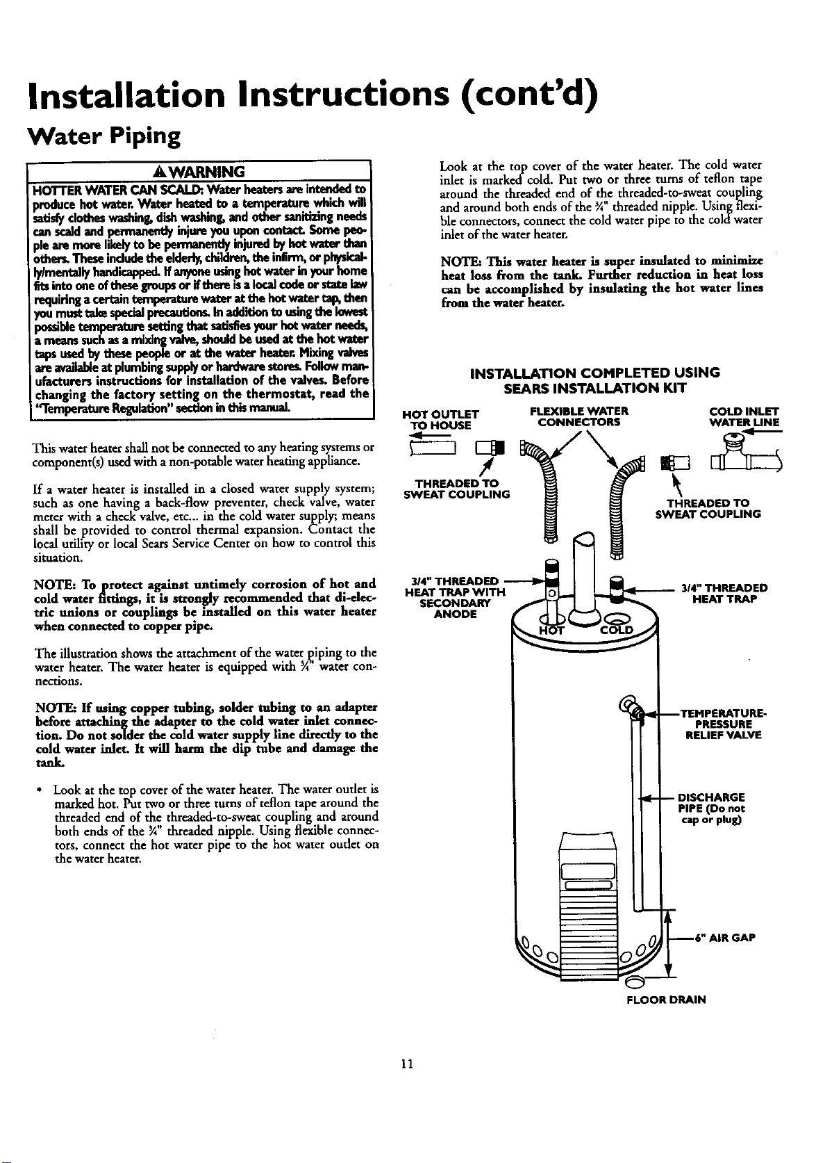
Look at the top cover of the water heater. The cold water
inlet is marked'cold. Put two or three turns of teflon tape
around the threaded end of He threaded-to-sweat cou[ling
and around both ends of the 3A threaded nipple. Usinl_ flexi-
ble connectors, connect the cold water pipe to the color warer
inlet of the water heater.
NOTE: This water heater is super insulated to minimize
heat loss from the tank. Further reduction in heat loss
can be accomplished by insulating the hot water lines
from the water heater.
INSTALLATION COMPLETED USING
SEARS INSTALLATION KIT
HOT OUTLET
TO HOUSE
THREADED TO
SWEAT COUPLING
FLEXIBLE WATER
CONNECTORS COLD INLET
WATER UNE
THREADED TO
SWEAT COUPLING
NOTE: Toprotect against untimely corrosion of hot and
cold water fittings, it is strongly recommended that di-elec-
tric unions or couplings be installed on this water heater
when connected to copper pipe.
The illustration shows the attachment of the water [iping to the
water heater. The water heater is equipped with ¾' water con-
nections.
NOTE: If using copper robing, solder tubing to an adapter
before attaching the adapter to the cold water inlet connec-
tion. Do not solder the cold water supply line directly to the
cold water inlet. It will harm the dip tube and damage the
tank.
•Look at the top cover of the water heater. The water outlet is
marked hot. Put two or three turns of teflon tape around the
threaded end of the threaded-to-sweat coupling and around
both ends of the ¾ threaded nipple. Using flexible connec-
tors, connect the hot water pipe to the hot water oudet on
the water heater.
3_"THREADED
HEAT TRAPWITH
SECONDARY
ANODE
%
314"THREADED
HEAT TRAP
-- DISCHARGE
PIPE (Do not
cap or plug)
--6" AIR GAP
FLOOR DRAIN
--TEMPERATURE-
PRESSURE
RELIEFVALVE
11
Installation Instructions (cont'd)
Temperature-Pressure Relief Valve
_,WARNING
At the time ofmanufacture this water heater wasprovided
with acombinationtemperature-pressuresreliefvalvecertified
by a nationallyrecognized testinglaboratorythat maintains
mriodic inspectionofproductionof listedequipmentor mate-
rials, as meeting the requirements for Relief Valvesand
AutomaticGasShutoffDevicesfor Hot Water SupplySystems,
and the latestedition of ANSI Z21.22and the coderequire-
mentsof ASMF.If replaced,the va_emust meetthe reqube-
mentsof localcodes,butnotlessthana combinationtempera-
ture andpressurerelief valvecertifiedasmeetingthe require-
mentsfor ReliefVabesandAutomaticGasShutoffDevicesfor
Hot Water SupplySystems,ANSI Z21.22byanaU.onallyrecog-
nized testing laboratorythat maintainsperiodic mspec_anof
productionoflistedequipmentor materi_
The valvemustbe markedwith amaximumsetpressurenot
to exceedthe marked bydrostatic workingpressureof the
waterheater(150 Ibsdsoein.)and a dischargecapacitynot less
thanthe wnterhEnterinputrateasshEwnon thEmodel reting
plate.(Electricheaters- watts dividedby 1000x 3415equal
BTU/Hr.rate.)
Yourlocaljurisdictionalauthority,whilemandatingthe useof a
temperature-pressorereliefvalvecomplyingwithANSI 7.21.22
andASNE, mayrequirea valvemodeldifferentfromthe one
fomisbedwiththewaterheater,
Compliancewith such_requirementsmustbe satlsEedby
theinstalleror enduserofthev_ter heaterwitha locallyp.re-
scribedtemperature-pressurereliefvalveinstalledin thedesig-
natedopeningin the water heaterin placeof the factoryfur-
nishedvalve.
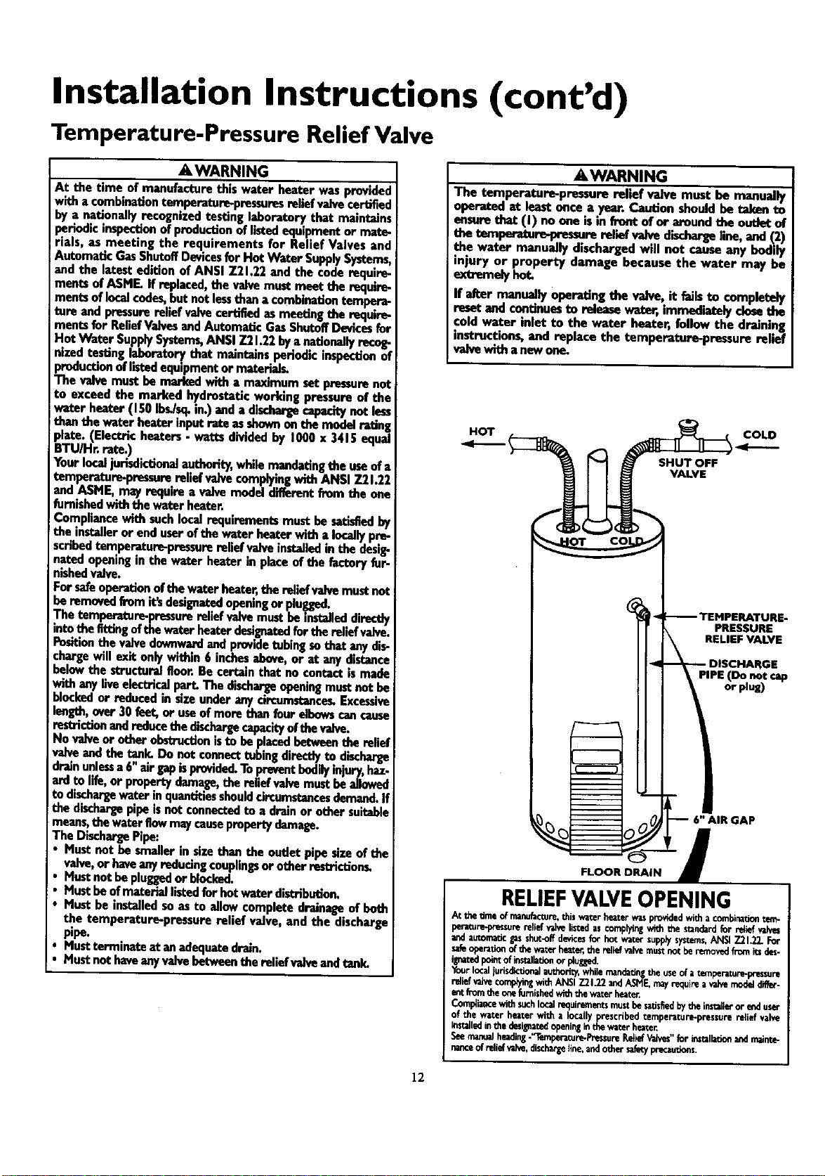
Forsafeoperationofthe waterheater,therailefvalvemustnot
beremovedfromit'sdesignatedopeningor plugged.
The temperature-pressurere||elv_e, mustbe inst_eddirectly
intothe fittingofthewaterheaterde_gnatedfor thereliefvalve.
Positionthe valvedownwardandprovidetubingsothatanydis-
chargewillexit onlywithin6 inchesabove,or at anydistance
belowthe structuralfloor.Becertainthat no contactismade
withanyllveelectricalpart.The dischargeopeningmustnot be
blockedor reducedin sizeunderanycircumstance_Excessive
length,ever30 feet,or useof morethan fourelbowscancause
restrictionandreducethedischargecapacityofthevalve.
No valveor otherobstructionisto beplacedbetweentherelief
v_ve andthEtank.Do netconnecttubingdirectlyte dlscherge
drainunlessa6"airgapisprovided.Topreventbodilyinjury,haz-
ardto life,or propertydamage,thereliefvalvemustbe allowed
todischargewater inquantitiesshouldcircumstancesdemand.If
the dischargepipeisnot connectedto a drainor othersuitable
means,the waterflowmaycausepropertydamage.
The DischargePipe:
• Mustnot be smallerin sizethanthe outletpipesizeof the
valve,or haveanyreducingcouplingsorotherrestHction_
• Mustnotbepluggedor blocl_l.
• Mustbeof materiallistedfor hotwaterdistribution.
• Must beinstalledsoasto allowcompletedrainageof both
the temperature-pressure relief valve, andthe discharge
pipe.
•Mustterminate atanadequatedrain.
•Mustnnthaveanyvalvebetweanthe reliefvalveandtank.
AWARNING
ThE temperature-pressurerelief valve must be manually
operatedat leastonce a year.Caution shouldbe takento
ensureth=e(I) noone isin frontof or aroundthe ontle'd:of
the temperature-pressure relief valvedischargeline,and(2)
the water manually dischargedwill not causeany bodily
injury or property damage because the water may be
extremelyhot.
If after manually operatingthe valve,it feJlsto completely
resetandcontinuesto releasewater,immediatelyclosethe
coldwater inlet to the water heater,follow the draining
blatructiens,and replacethe tempera|ore-pressureretief
valvewitha newone_
HOT
SHUT OFF
VALVE
COLD
PRESSURE
RELIEF VALVE
DISCHARGE
PIPE (Do not
or plug)
FLOOR DRAIN
RELIEFVALVEOPENING
At thetimeofmanufacture,thiswaterheaterwasprovidedwitha combinationtem-
peratu_re reliefvalvelistedascomplyingwiththe slandardfor rdief valves
andautomaticgas|hut-off devicesfor hotwatersupplysystems,ANSI7.21_2.For
safeopera,onofthewa_er_er, the_ _ve re.stnotberemovedfrom_ des-
ignatedpointofinstalla_onor plugged.
Yourlocaljurisdic_onalauthori_,whilemandatingthe useof a temperatur_pressure
reliefvaJvecomplyingwithANSIZ21.22andASME_mayr_quireavalvemodeldiffer-
er_fromd_ o_efur_fl_ed_h thev_,.erhe_er.
Compliancewithsuchlocalrequirementsmustbes_tisfiedbytheins_lerorenduser
of the water heaterwitha locallyprescribedtemperature-pressurenllief valve
Installedinthedasil_atec[openingIn_waterheater
Seemanualhe_ling-'1_.mpe_tur_-Pre_sureRetiefValves"for In_llatio_ andmaint_
nanceof reliofva_, dischargeline,andother_y I_-,cau_ons.
12
Installation Instructions (cont'd)
Filling the Water Heater
ACAUTION
Neverusethlswater henterunlassit iscompintelyfilledwith
Iwater.Topreventdamageto the tenk, the tenk must befilled
with water. Water must flow from the hot water mucet
Iboforeturning"ON" gasto thewaterheater.
For proper venting in certain installations, alarger diametervent
pipe may be necessary. Due to great variancesin installations,
unforeseeable by the manufacturerof the water beater, you must
consult your gas company to aid you in determining me proper
venting for your water heater from the vent tables in the latest
edition of the National Fuel Gas Code ANSI Z223.1, also
referredto asNFPA 54.
To fill the water heater with water:
•Close the water heater drain valve by turning the handle to
the right (clockwise). The drain valve is on the lower front of
the water heater.
• Open the cold water supply valve to the water heater.
NOTE: The cold water supply valve must be left open
when the water heater is in use.
•To insure complete filling of the tank, allow air to exit by
opening the nearest hot water faucet. Allow water to run
until a constant flow is obtained. This will let air out of the
water heater and the piping.
• Check all new waterpiping for leaks.Repair_ needed.
Venting
AWARNING
VENT DAMPERS- Any ventdampe_whetherit isoperat_l
thermallyor otherwisemustberemovedifitsuseinhn3itsprop-
erdraftingofthewaterbea_r.
ThermallyOperatedVentDamper_ Gas-firedwater heaters
havingthermal eflkiancyinexcessof B0%mayproducea mla-
tlvelylowfluegastemperature.Suchtemperatures maynotbe
high enough to properly open thermally operated vent
damper_This wouldcausespillageof fluegasesandmaycause
carbonmonexidepoisoning.
Ventdampersmust bearevidenceof cer'dfam_ as€omplying
with the latesteditionof AmericanNationalStandardANSI
7.21.68(ANSI 7.21.66& 67, respectively,coverelectricallyand
mechanicallyactuatedventdampers).Beforeinstallationofany
ventdamper,consultyour localSexrsServiceCanterorthe gas
utilityforfurtherinfonnatlo_
AWARNING
To insureproperventingof this gas-firedwater heater,the
correctventpipediametermustbeutilized.Anyadditionsor
deletionsofothergasapplianceson acommonventwith this
water heater mayadverselyaffect the operationofthe water
benter. Consultthe localSearsServiceCenteror gasutilityif
anysuchchangesam planned.
Check the venting system for signs of obstruction or deteriora-
tion and replace ifneeded.
The combustion and ventilation airflow must not be obstructed.
I AWARNING
Obstructeder deterioratedventaystemsm_ presentasertons
beaithriskorasphl_tio_
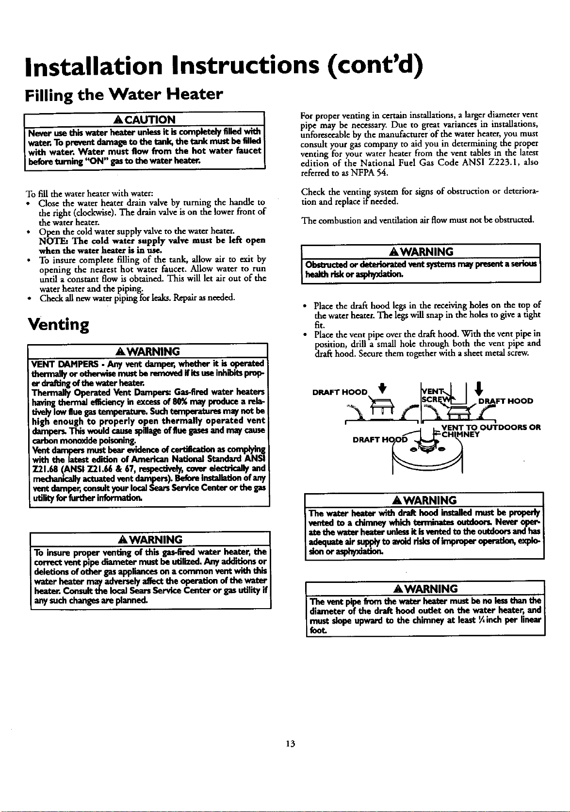
•Place the drafthood legsin the receiving holes on the top of
the water heater. The legs will snap in the holes to give atight
fit.
• Place the vent pipe overthe drafthood. With the vent pipe in
position, drill a small hole through both the vent pipe and
drafthood. Secure them together with a sheet metal screw.
DRAFT HOOD t _VENTNI I !
,. _===k ISCR_E____I DRAFT HOOD
LVENT TO OUTDOORS OR
AWARNING
-ri_ _g_- ix_€_ wlm dra_ ho_l ,,_lled mustbe pmlx_ I
ventedto a chimneywhichterminates otmfuorLNerer ope_ I
Iatethe waterhexterunlassitisvanted..,te the ontdonrsandhasI
Iadequateairsuppiyto avoidrisksof m_roper operation,expio-1
II
AWARNING I
Theventpipefrom thewaterhextermustbeno lessthan theI
diameterof the draft hoodoutlet on the wa.,.t_"heater,and
slopeupwardto the chimneyat least¼,nch per linearI
13
Installation Instructions (cont'd)
Venting (cont'd) Gas Piping
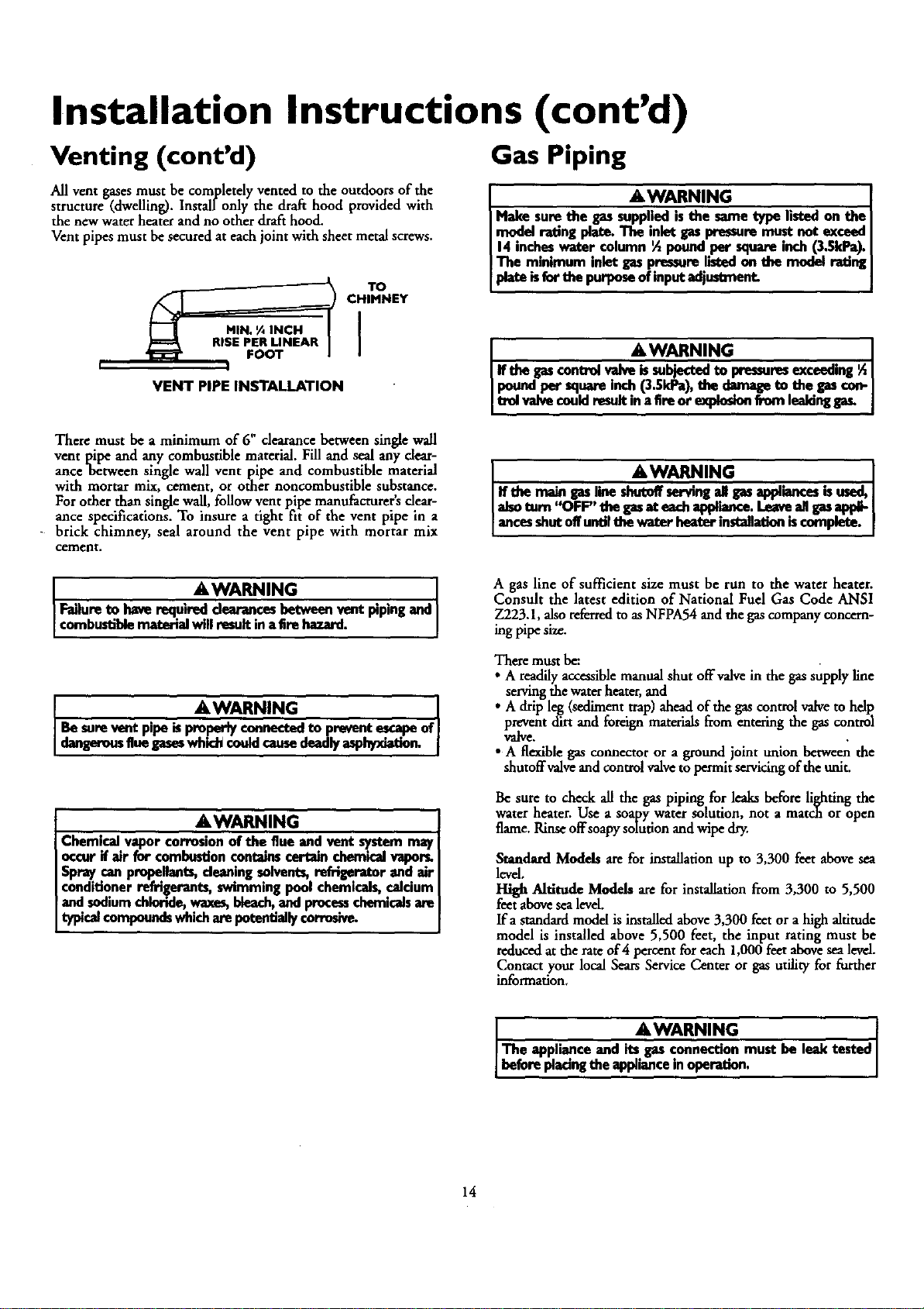
All vent gases must be completely vented to the outdoors of the
structure (dwelling). Installonly the draft hood provided with
the new water heater and no other draft hood.
Vent pipes must be secured at each joint with sheet metal screws.
FOOT I
!
TO
CHIMNEY
VENT PIPE INSTALLATION
AWARNING
Make sure the gas supplied is the same type listed on the
I .n_<l.el rating plate. The inlet gas pressure must not exceed
[ 14 mcbes water column ½pound.per square inch (3.5k.Pa).I
I The minimum inlet gas pressure !isled on the model rating I
[is of put justmant j
AW.ARNiNG I
ff the gascontrol valve is subjected to pressuresmtceeding ½
pound per square inch (3.5kPa), the damage to the gascon-
trel vaive conld result n a fire or explos_n from leakinggas.
There must be aminimum of 6" dearance between single wall
vent pipe and any combustible material. Fill and seal any dear-
anee between single wall vent pipe and combustible material
with mortar mix, cement, or other noncombustible substance.
For other than single wall, follow vent pipe manufacturer'sdear-
ance specifications. To insure a tight fit of the vent pipe in a
brick chimney, seal around the vent pipe with mortar mix
cement.
&WARNING I
iff themaingaslineshutoffservingal gasap_ioncesisused,I
I_so turn "OFF" the gasat eachappI.Eu_e.Leaveail gasapl_ I
Iances shut off until the water heater mstaEationis complete. I
AWARNING
Failureto haverequired_ces betweenventpipingand
combustiblematerialwl result nafire hazard.
AWARNING l
Be sure rant pipe is properly connected to pmvant escape of
dangerousfluegaseswhichcouldcausedeadlyasphyxiation.
AWARNING
Chemical vapor corrosion of the flue and vent system may
occur if air for combustion contains certain chemical vapors.
Spray can pro_. Ihnts, dean!ng solvents, refrigerator and air
conditioner refrigerants, svnmming pool chemicals, calcium
and sodium chloride, waxes, bleach, and processchemicalsare
typicalcompoundswhicharepotendailycorrosive.
Agas line of sufficient size must be run to the water heater.
Consult the latest edition of National Fuel Gas Code ANSI
Z223.1, alsoreferred to as NFPA54 and the gascompany concern-
ing pipe size.
There must be:
•Areadily accessible manual shut offvalve in the gas supply line
servingthe water heater, and
•A drip leg(sediment trap) ahead of the gascontrol valveto help
prevent dirt and foreign materials from entering the gas control
valve.
•A flexible gas connector or aground joint union between the
shutoff valveand control valveto permit servicingof the unit.
Be sure to check all the gaspiping for leaks before lighting the
water heater. Use a soapy water solution, not a match or open
flame.Rinse offsoapy soludon and wipe dry.
Standard Models are for installation up to 3,300 feet above sea
level.
High Altitude Models are for installation from 3,300 to 5,500
feet above sea level.
Ifa standard model is installed above 3,300 feet or a high altitude
model is installed above 5,500 feet, the input rating must be
reduced at the rate of 4percent for each 1,000 feet above sea level.
Contact your local Sears Service Center or gas utility for forther
information.
.AWARNING
The apphance and its..gas connection must be lear tested
before placingthe appimnce in opel-adon.
14
Installation Instructions (cont'd)
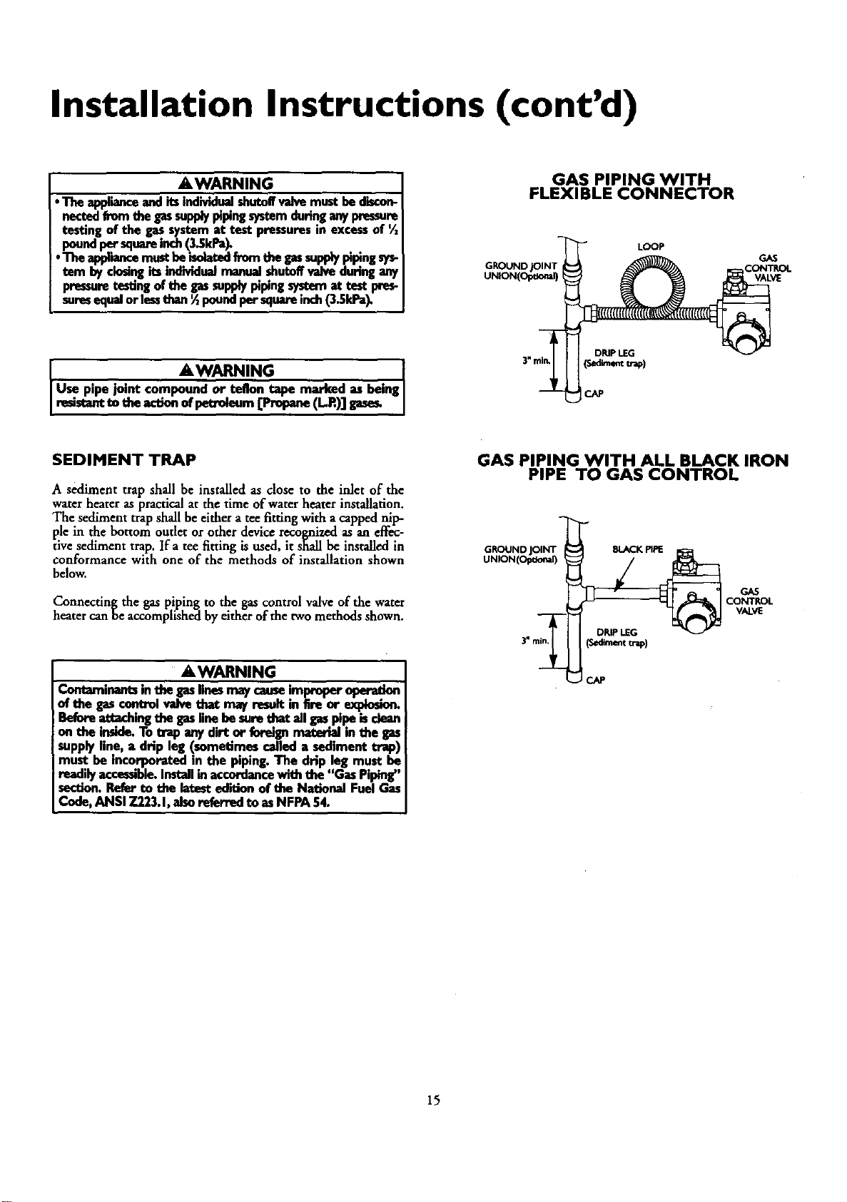
AWARNING
• The applianceandits individualshutoffvalvemustbediscon-
nectedfromthe gassupplypipingsystemduringanypressure
testingof the gassystemat test pressuresin excessof
•poundpersquareinch(3._ld_
tern byclosingitsindividualmanualshutx_ valvedunngan1
pressuretestingofthegassupplypiping_ at test pres-
suresequalorlessthan_poundpersquareinch(3.51d_
GAS PIPING WITH
FLEXIBLE CONNECTOR
LOOP
GROUND GAS
VALVE
JAWARNING I
Use pipe joint compoundor teflon tape marked as beingJ
resistantte theactionofpeU'oleum[Propane(L.R)]gases, j
DRIPLEG
_,d_nem trap)
CAP
SEDIMENT TRAP
A sediment trap shall be installed as close to the inlet of the
water heater as practical at the time of water heater installation.
The sediment trap shall be either a tee fitting with a capped nip-
ple in the bottom outlet or other device recognized as an effec-
tive sediment trap. Ifa tee fitting is used, it shall be installed in
conformance with one of the methods of installation shown
below.
Connecting the gas piping to the gas control valve of the water
heater can be accomplished by either of the two methods shown.
AWARNING
Contaminantsinthegaslinesmaycause!mproper oper_on.
of the gascontrolvalvethat may result|n fire or expiosJor_
Beforeattechingthegaslinebe surethat ell gaspipe isdean
on the inside.To.trapanydirt or foreignmaterialin the gas
supplyline, a drip leg (seme'dmescalleda sedimenttrap)
must be incorporatedin the piping.The drip leg must be
readilyaccessible.Installinaccordance_the "Gas Piping"
section.Referto the latestedition ofthe NationalFuelGas
Code,ANSI 7.223.1,alsoreferredto asNFPA54.
GAS PIPING WITH ALL BLACK IRON
PIPE TO GAS CONTROL
GP,OUND JOINT _BLACK PIPE
UNiON(Opuona0_GAS
3" VALVE
_jm
15
Installation Instructions (cont'd)
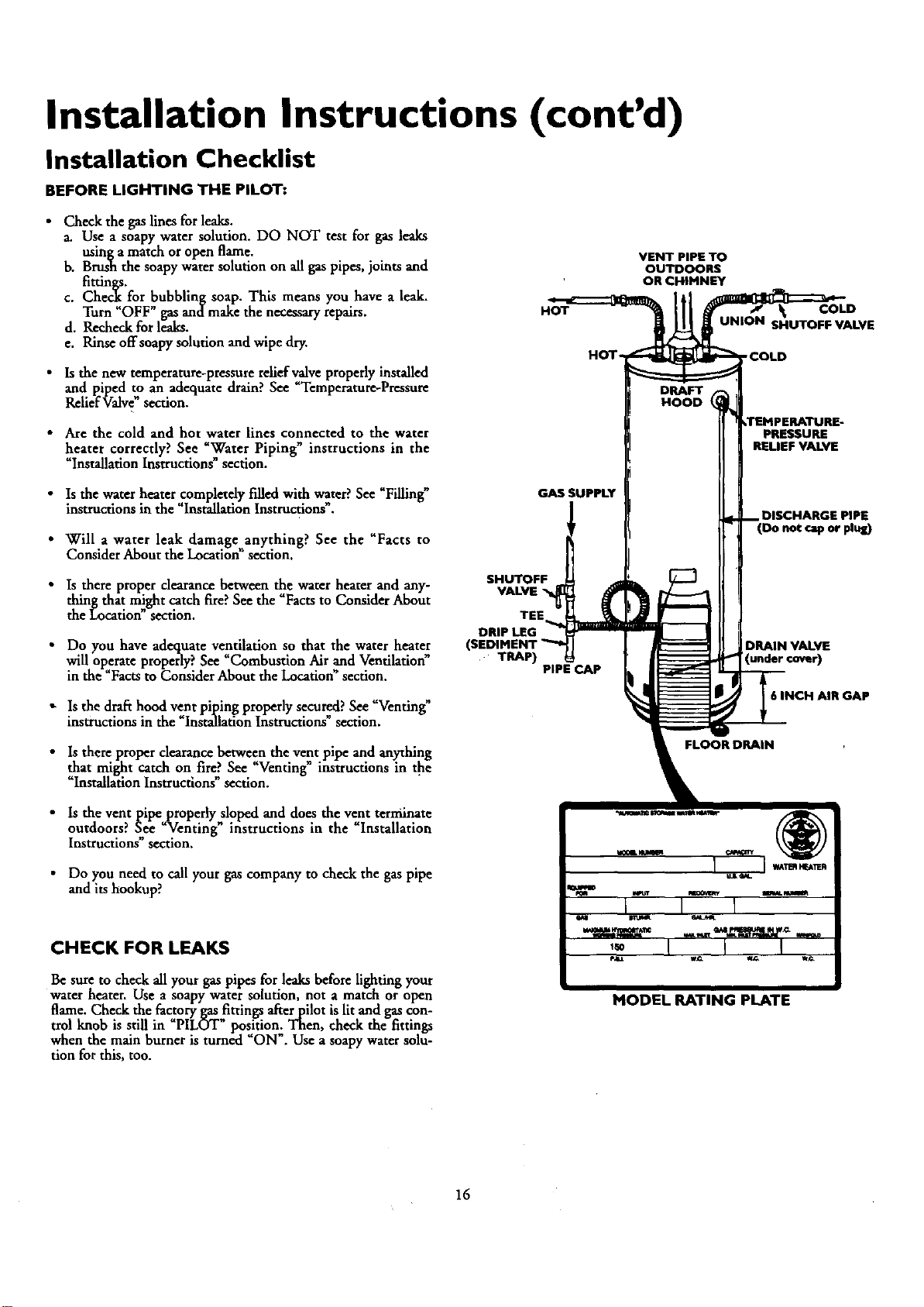
Installation Checklist
BEFORE LIGHTING THE PILOT:
•Check the gas lines for leaks.
a. Use a soapy water solution. DO NOT test for gas leaks
usinga match or open flame.
b. Brush the soapy water solution on all gas pipes, joints and
c. Che for bubbling soap. This means you have a leak.
Turn OFF gas andmake the necessary repairs.
d. Recheck for leaks.
e. Rinse offsoapy solution and wipe dry.
•Is the new temperature-pressure relief valve properly installed
and Dped to an adequate draan. See Temperature-Pressure
ReliefValve" section.
HOT
HOT-
VENT PIPE TO
OUTDOORS
OR CHIMNEY
COLD
UNION SI_IUTOFF VALVE
'COLD
• Are the cold and hot water lines connected to the water
heater correctly? See "Water Piping" instructions in the
"Installation Instructions"section.
PRESSURE
RELIEF VALVE
• Is the water heater completely filled with water? See _Filling"
instructions in the "Installation Instructions .
• Will awater leak damage anything? See the "Facts to
Consider About the Location" section.
• Is there proper clearance between _e water heater and any-
thing that might catch fire?See the Facts to Consider About
the Location" section.
• Do you have adequate ventilation so that the water heater
will operate properly? See "Combustion Air and Ventilation
in the _Factsto Consider About the Location"section.
"" ly "" "" Is the draft hood vent piping proper secured. See Venung_
instructions In the Installatmn Instructmns sectmn.
GAS SUPPLY
SHUTOFF
VALVE "_
TRAP) PIPE CAP
DISCHARGE PIPE
(Do not cap or plug)
DRAIN VALVE
INCH AIR GAP
•Is there proper clearance between the vent pipe and anything
that might catch on fire?See _Venting instructions in the
"Installation Instructions" section.
• Is the vent pipeproperly sloped and does the vent terminate
outdoors? See "-Venting" instructions in the "Installation
Instructmns sectaon.
• Do you need to call your gas company to check the gas pipe
and its hookup?
CHECK FOR LEAKS
Be sure to check all your gas pipes for leaks before lighting your
water heater. Use a soapy water solution, not amatch or open
flame. Check the factory gasfittings after pilot is lit and gas con-
trol knob is still in PILOT position,; Then, check the fittings
when the main burner is turned "ON . Use a soapy water solu-
tion for this, too.
MODEL RATING PLATE
16
Operating Instructions
Lighting
_,WARNING
BEFOREUGHTING PROPANE(L.R)GASWATERHEATERS:
Propane(I-P.)gasisheavierthanair.Shouldtherebealeakin
the system,the.gas will settlenear the ground.Basements,
crawlspaces,skirted areasundermobile homes(evenwhen
ventilated),closetsandareasbelowgroundlevelwill serveas
for theaccumulationofthis ga_ Beforeattemptingto
lightor relight_water beater_pilotor turningon a nearby
electricallightswitch,beabsolutelysumthereisnoaccumulet.
edgasinthe are_ Searchfor odorof gasbymit§ng at ground
levelin thevicinityof theappliance.It'odoris detected,follow
stepsindicatedat "For YourSa_' onthe coverpageof this
manualtbenleavethepremise_
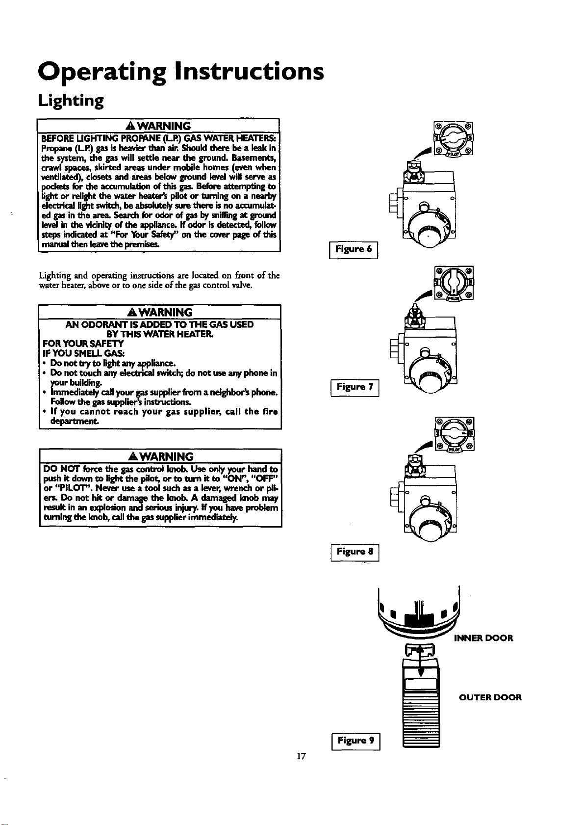
Lighting and operating instructions are located on front of the
water heater, aboveorto oneside of the gas control valve.
AWARNING
AN ODORANT ISADDED TO THE GASUSED
BYTHIS WATER HEATER.
FORYOUR SAFETY
IF YOU SMELLGA_
• Do net tryto lightanyappliance.
Do nottouchanyelectricalswitch;donot useanyphonein
yourbuildin_
immediatelycallyourgassupplierfrom aneighbor'sphone.
Followthegassupplier_instructio_
If you cannot reach your gas supplier, call the fire
AWARNING
DoNOT ..U.. ob.U... h ndto
pushit downto hghtthe plot, or to tom it to "ON", "OFF"
or "PILOT". Never useatoolsuchasa lever,wrenchor pli-
er_ Do not hit or.damageth.e.knob.A damagedImobmay
resultin anexplo_onandseriousinjury.Ifyouhavepmb_m
turningthe knob,callthe gassupplierimmnd'mtely.
Figure 6]
Figure 7 1
Figure 8 ]
OUTER DOOR
Figure 9 ]
17
Operating Instructions (cont'd)
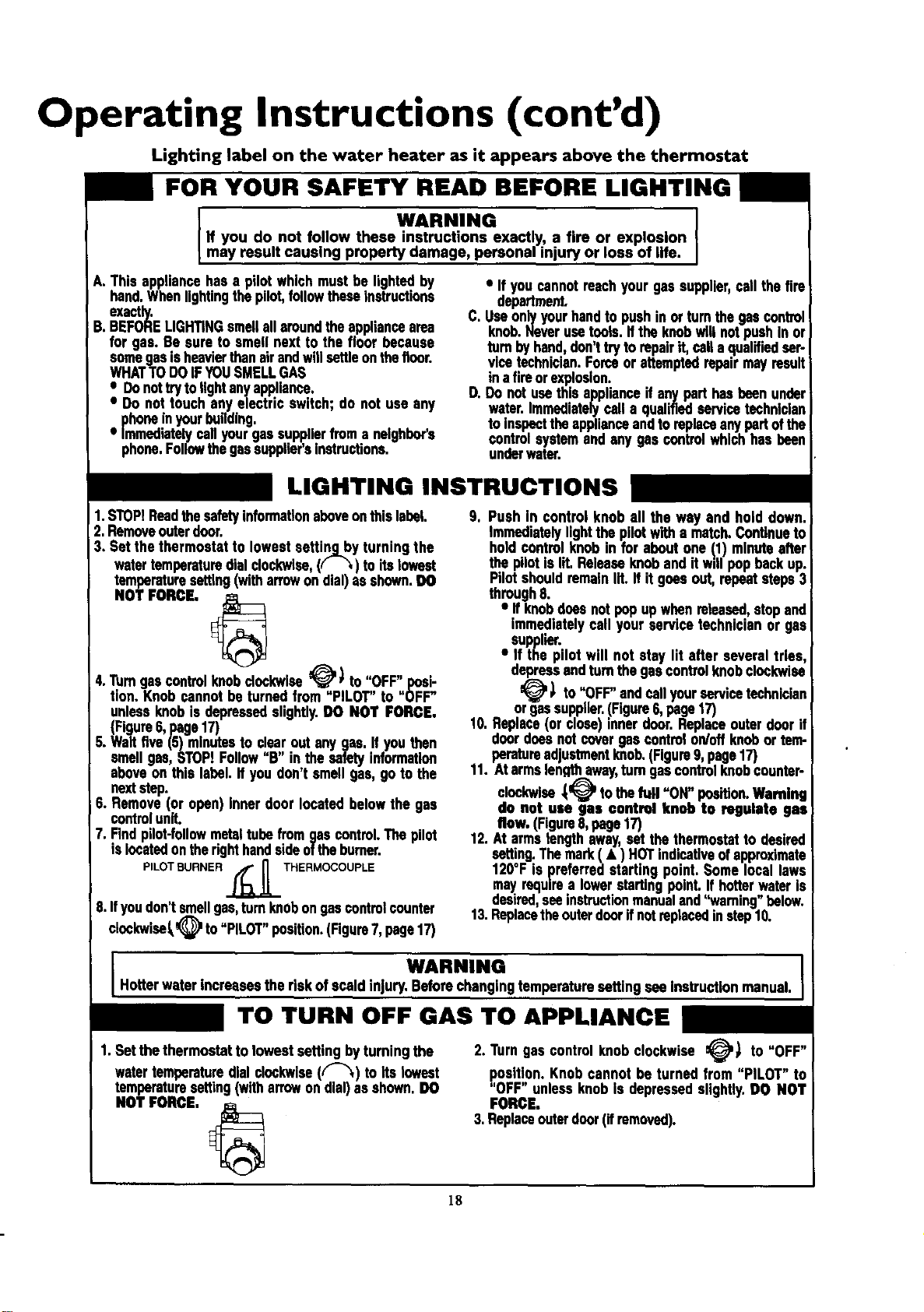
Lighting label on the water heater as it appears above the thermostat
FOR YOUR SAFETY READ BEFORE LIGHTING
WARNING
If you do not follow these instructions exactly, a fire or explosion
may result causing property damage, personal injury or loss of life.
A. This appliancehasa p,ot whichmusthe lightedby
hand.Whenlightingthepilot,followtheseInstructions
exactly.
B.BEFORELIGHTINGsmellall aroundtheappliancearea
for gas. Besure to smell nextto the floor because
somegasisheavierthanairandwill settleonthefloor.
WHATTODOIFYOUSMELLGAS
• Donottrytolightanyappliance.
•Do not touchanyelectricswitch; do not use any
phoneinyourbuilding.
• Immediatelycallyourgassupplierfroma neighbor's
phone.Followthegassupp,er'sInstructions.
•Ifyou cannotreachyourgassupplier,call thefire
department.
C. Useonlyyourhandto pushinor turnthegascontrol
knob.Neverusetoots,if theknobwillnotpushIn or
turnbyhand,don'ttryto repairit,calla qualifiedser-
vicetechnician.Forceor attemptedrepairmay result
in a fireorexplosion.
D. Donot usethis applianceif anypart hasbeenunder
water.Immediatelycalla qualifiedservicetechnlclan
to Inspecttheapplianceandto replaceanypartofthe
controlsystemand anygas controlwhichhasbeen
underwater.
LIGHTING INSTRUCTIONS
1.STOP!Readthesafetyinformationaboveonthis label.
2.Removeouterdoor.
3. Set thethermostatto lowestsetting byturningthe
watertemperaturedialclockwise,(( _,)toitslowest
temperaturesetting(witharrowondial)asshown.DO
NOT FORCE, _
4."rumgascontrolknobclockwise__) to ';,OFF'I,nosi-
tlon. Knobcannotbe turnedfrom PILOT to (_FF"
unlessknob isdepressedslightly.DO NOT FORCE,
(Figure6,page17)
5.Waitfive (5)minutes to clearout anygas.If youthen
smellgas,STOPIFollow"B" inthe safetyinformation
aboveon this label.If youdon'tsmell gas,go to the
nextstep.
6. Remove(or open)Innerdoor locatedbelowthe gas
controlunit.
7. Findpilot-followmetaltubefromgascontrol.Thepilot
islocatedontherighthandsideoftheburner.
PILOT BURNER _ _ THERMOCOUPLE
8.Ifyoudon'tsmellgas,turnknobongascontrol counter
clockwise_ to"PILOT"position.(Figure7,page17)
9. Push in control knob all the way and hold down.
Immediatelylightthe pilotwitha match.Continueto
holdcontrolknobin for aboutone !1) minuteafter
thepilotislit. Releaseknob andit willpopbackup.
Pilotshouldremainlit.If it goesout,repeatsteps3
through8.
• if knob doesnotpopupwhenreleased,stopand
immediatelycall yourservice technicianor gas
supplier.
• If the pilot will not stay lit after several tries,
depressandturnthegascontratknobclockwise
_' _ to"OFF"andcell yourservicetechnician
orgassupplier.(Figure6,page17)
10.Replace(or close)innerdoor.Replaceouterdoorif
doordoesnotcovergascontrolon/offknobor tem-
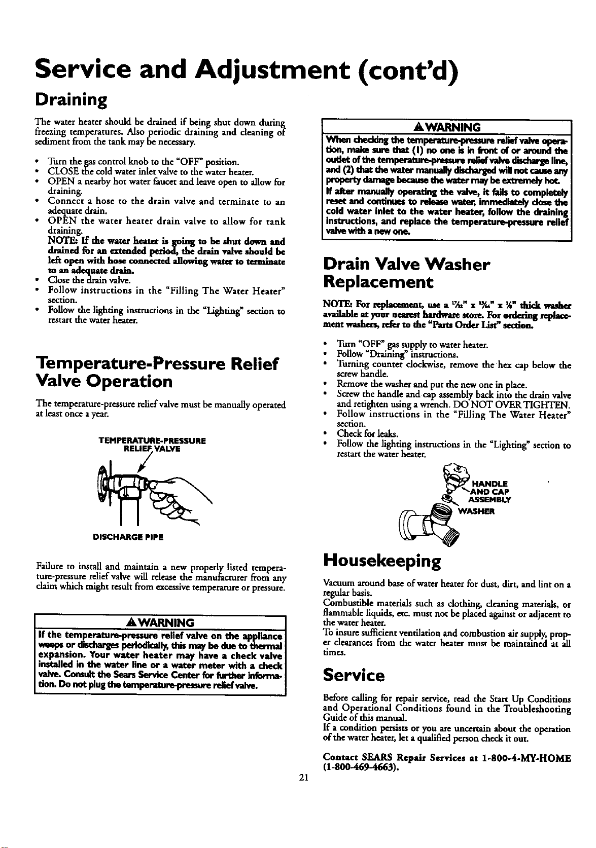
peratureadustmeotknob.(Figureg,page17)
11. Atarms engthaway,turngascontrolknobcounter-
clockwise_)P tothefull "ON" position.Wanting
do not use gas control knob to regulate gas
flow. (Figure8,page17)
12.At armslengthaway,set thethermostatto desired
setting.Themark ( • ) NOTindicativeofapproximate
120°F is preferredstarting point. Somelocallaws
mayrequirea lowerstartingpoint. If hotterwateris
desired,seeinstructionmanualand='warning"below.
13.Replacetheouterdoorif notreplacedinstep10.
WARNING I
Hotterwater ncreasesthe riskof scaldinjury.Beforechangingtemperaturesetting seeInstructionmanual. I
TO TURN OFF GAS TO APPLIANCE
1.Set thethermostatto lowestsettingbytuming the
watertemperaturedialclockwise(("-"_) to its lowest
temperaturesetting(witharrowondial)as shown.DO
NOT FORCE. _
2. Turngas controlknobclockwise _) to "OFF"
position.Knobcannotbe turned from "PILOT" to
"OFF" unlessknobIs depressedslightly.DO NOT
FORCE,
3.Replaceouterdoor(ifremoved).
18
Operating Instructions (cont'd)
Temperature Regulation
Due to the nature of the typical gas water heater, the water tem-
>oeraturein certain situations may vary up to 30°F higher or
wer at the point of use such as, bathtuus, showers, sink, etc.
This means that when the temperature adjustment dial is set at
the mark approximating 120°F, the actual water temperature at
any hot water tap could be as high as 150°F or as low as 90°E
Any water heater's intended purpose is to heat water. Hot water
is needed for cleaning (bodies, dishes, clothing). Hot water will
present a scald hazard. Depending on the time element, and the
people involved (normaladults, children, toddlers, elderly,
infirm, etc.) scalding may occur at different temperatures.
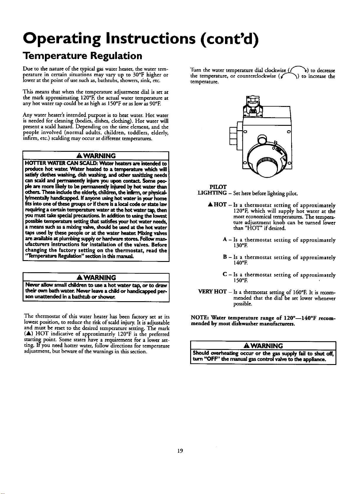
Turn the water temperature dial clockwise.Lff"_) to decrease
the temperature, or counterclockwise (€_ _) to increase the
temperature.
AWARNING
HOTTERWATERCAN SCAL_.Water heatersamintendedto
producehot water.Water heatedto a temperaturewhichwill
satisfyclotheswashing,dishwashing,anduther sanitizingneeds
canscaldandpermanentlyinjureyouuponcontatt.Somepeo.
pieamrnoreI!kelyto bepennanontlyinjuredbyhutwat_-than
others.Theseincludethe elderly,children,theinfirm,orphysical-
lylmentally handicapped.Ifanyoneusinghotwaterinyourhome
fitsinto oneofthesei_roupsorifthereisaincalcodeorstatelaw
requiringacertaintemperaturewateratthehotwater_then
youmusttakespecialprecautionsInadditiontousingthelowest
possibletemperaturesettingthatsatisfiesyourhotwaterneeds,
a meanssuchasa mixingvalve,shouldbeusedat thehotwater
tapsusedbythesepeopleor at the waterhea_r.Mixingvalves
areavailableat plumbingsupplyor hardwarestore_Followman-
ufactorersinstructionsfor installationof the valves.Before
changingthe factory setting on the thermostat, read the
'q'emperatoreRegulation"sectioninthismanual.
AWARNING ]
Neverallow smallchildron--ron----m--_auseausea hot watertap, or to drawI
their ownbath_Neverleaveachild or handicappedper- I
sonunattondedma bathtubocshower. J
The thermostat of this water heater has been factory set at its
lowest position, to reduce the risk of scald injury. It is adjustable
and must be reset to the desired temperature setting. The mark
(A) HOT indicative of approximately 120°F is the preferred
starting point. Some states have a requirement for a lower set-
ting. If you need hotter water, follow directions for temperature
adjustment, but beware of the warnings in this section.
PILOT
LIGHTING -Set here before lighting pilot.
AHOT- Is a thermostat setting of approximately
120°F, which will supply hot water at the
most economical temperatures. The tempera-
ture adjustment knob can be turned lower
than "HOT" if desired.
A - Is athermostat setting of approximately
130°E
B - Is a thermostat setting of approximately
140°E
C-Is a thermostat setting of approximately
150°E
VERYHOT - Is a thermostat setting of 160°E It is recom-
mended that the dial be set lower whenever
possible.
NOTE: Water temperature range of 120°--140°F recom-
mended by moat dishwasher manufacturers.
•AWARNING
Shouldoverheatingoccuror the gassupplyfailto shutoff,
turn"OFF" themanualgascontrolvalveto theapp ance.
19
Service and Adjustment
Tank (Sediment) Cleaning
Sediment build-up on the tank bottom may create varying
amounts of noise, and if left in the tank will cause premature
tank failure. In some water areas, you may not be able to drain
all sediment deposits by simply draining the tank. In these cases
Mag Erad (part no. 23600) can be used to help remove the sedi-
ment deposits. This may be ordered from the Sears Service
Center. For ordering, refer to the 'Parts Order List" sect'on.
Burner Inspection
AWARNING
Donotusethisapplianc_has beanuedorwa_. I
Immediately call a Sears Service Technician to inspect the
appliance and to replace the gas control or any part of the
humorsystomwhchhasbeanundorwater, j
Venting System Inspection
At least once a year a visual inspection should be made of the
venting system. Youshould look for:
• Obstructions which could cause improper venting. The com-
bustion and ventilation air flow must not be obstructed.
iamage or deterioration which could cause improper vant-
ing or_eakageof combustion products
Rustedflakesaround top of water heater.
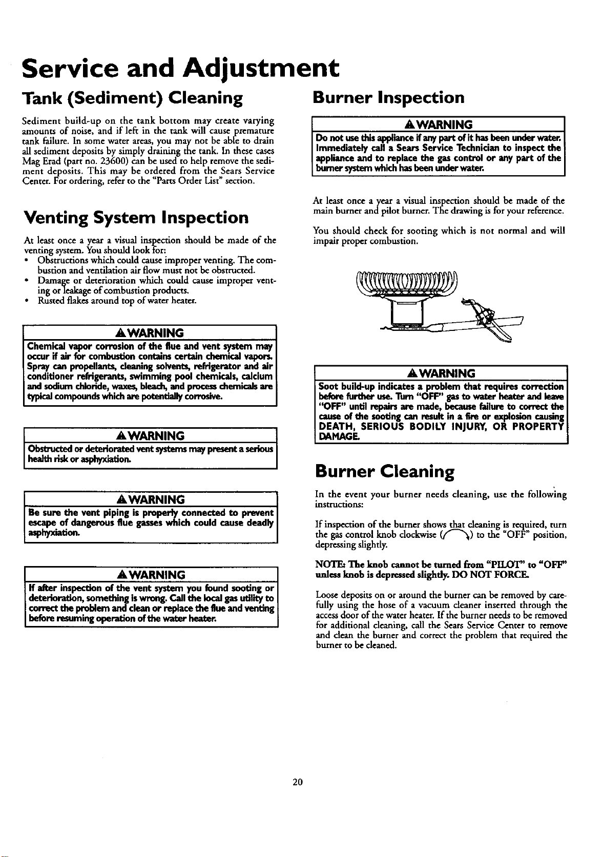
At least once a year avisual inspection should be made of the
main burner andpilot burner. The drawingis for your reference.
You should check for sooting which is not normal and will
impair proper combustion.
AWARNING
Chemical vapor corrosion of the flue and vent system may
occur if air for combustion contains certain chemical vapor_
Spray can propellants, cleaning solvents, refrigerator and air
conditioner refrigerants, swimming pool chemicals, calcium
and sodium chloride, waxes, bleach,and processchemicals
typical compoundswhich are potantially corrosive.
•AWARNING
Obstro .c.,_1,or detenoreted vent systemsmay present aserious
healthrisk orasphyxiation.
AWARNING I
Be sure the vent piping is properly.connected to prevent
aspeSCapehyxio.fa_dTgerous flue gassoswh,ch coud cause deadly
AWARNING . [
If a_.r inspection of the vent system you found sooting or [
deterioration, something iswrong. Call the local gasutility to [
correct the problem _clean or replace the flue and venting
before resuming operation of the water heater.
AWARNING
Soot build-upindicatesaproblemthat requires correction
beforefurtheruse.Turn"OFF" gasto water heaterand leave
"OFF" untilrepairsare made,becausefailureto conect the
causeofthe sootingcanresultin afire or explosmncausing
DEATH, SERIOUS BODILY INJURY, OR PROPERTY
DAMAGE.
Burner Cleaning
In the event your burner needs cleaning, use the following
instructions:
If inspection of the burner shows that cleaning is required, turn
the gas control knob clockwise (_"x) to the OFF position,
depressing slightly.
NOTE: The knob cannot be turned from "PILOT" to "OFF"
unless knob is depressed sfightly. DO NOT FORCE.
Loose deposits on or around the burner can be removed by care-
fully using the hose of a vacuum cleaner inserted through the
accessdoor of the water heater. If the burner needs to be removed
for additional cleaning, call the Sears Service Center to remove
and dean the burner and correct the problem that required the
burner to be cleaned.
20
Service and Adjustment (cont'd)
Draining
The water heatershould be drained if being shut down during
freezing temperatures. Also periodic draining and cleaning of
sediment from the tank maybe necessary.
Turn the gascontrol knob to the "OFF" position.
CLOSE the cold water inlet valve to the water heater.
•OPEN a nearby hot water faucet and leave open to allow for
draining.
• Connect a hose to the drain valve and terminate to an
adequate drain.
•OPEN the water heater drain valve to allow for tank
draining.
N.O_ If the water heater is going to be shut down and
drained for.an extended perlod, the drain valve should be
left open with hose connected allowing water to terminate
to adeq t d h.
•Close the drain valve.
• Follow instructions in the _Filling The Water Heater"
$¢ction.
• Follow the lighting iustructions in the "Lighting" section to
restartthe waterheater.
AWARNING
When checldngthe temperature-prasmra relief valve opera,
fion, make rare that (I) ne one Is infront of er around the
outi_ ofthe temt_nture.pemmm nd'_ discharSoline,
and(2) thatthewater manuallydischargedwillnotcanseany
propertydamagebecamethewm_rmaybeextram_ ho_
If after manuallyoperatingthe valve,it failsto completely
resetand continuesto releasewater, immediatelyclosethe
cold water inlet to the water heater, follow the draining
instructions,and replace the ternperatore-pressure relief
valvewithanewone_
Drain Valve Washer
Replacement
NOTE: For replacement, me a 17/n"• u_h"• _" thick washer
available at your nearest hasdware store. For o_ mplaco.
meat washtmhreferto the "Parts Order List_sconen.
Temperature-Pressure Relief
Valve Operation
The tempetature-pressurereliefvalve must be manually operated
at leastonce a year.
TEMPERATURE-PRESSURE
REL_ VALVE
Turn "OFF" gas supplyto water heater.
Follow _Draining" instructions.
Turning counter clockwise, remove the hex cap below the
screw handle.
Remove the washer and put the new one in place.
Screw the handle and cap assembly backinto the drainvalve
and retighten using a wrench. DO NOT OVER TIGHTEN.
Fol!ow instructions in the Pilling The Water Heater"
section.
Check for leaks.
Follow the lighting instructions in the "Lighting" section to
restartthe water heater.
"_'AND CAP
ASSEMBLY
DISCHARGE PiPE
Failureto install and maintain a new properly listed tempera-
tore-pressure relief valve will release the manufacturer fronl any
claim which might result from excessivetemperature or pressure.
AWARNING
If the temperatura-prassure relief valve on the appliance
wnepsor dischargesperfodicadl_this maybedue tu thermal
expansion. Your water heater may have acheck valve
installedin the water line or a water meter with a check
valve.Comuit theSearsService Center for further Infomm.
tion.Do notplugthetemperature-pressurereliefvalve.
Housekeeping
Vacuum around base of water heater for dust, dirt, and lint on a
regular basis.
Combustible materials such as dothingo denning materials, or
flammable liquids, etc. must not be placed against or adjacent to
the water heater.
To insure sufficient ventilasion and combustion air supply, prop-
er ' " - --
dearances from the water heater must be maintained at all
times.
Service
Before calling for repair service, read the Start Up Conditions
and Operational Conditions found in the Troubleshooting
Guide of this manual.
If a condition persists or you are uncertain about the operation
of the water heater, let a qualified person check it out.
Contact SEARS Repair Services at 1-800-4-MY-HOME
(1-800-469-4663).
21
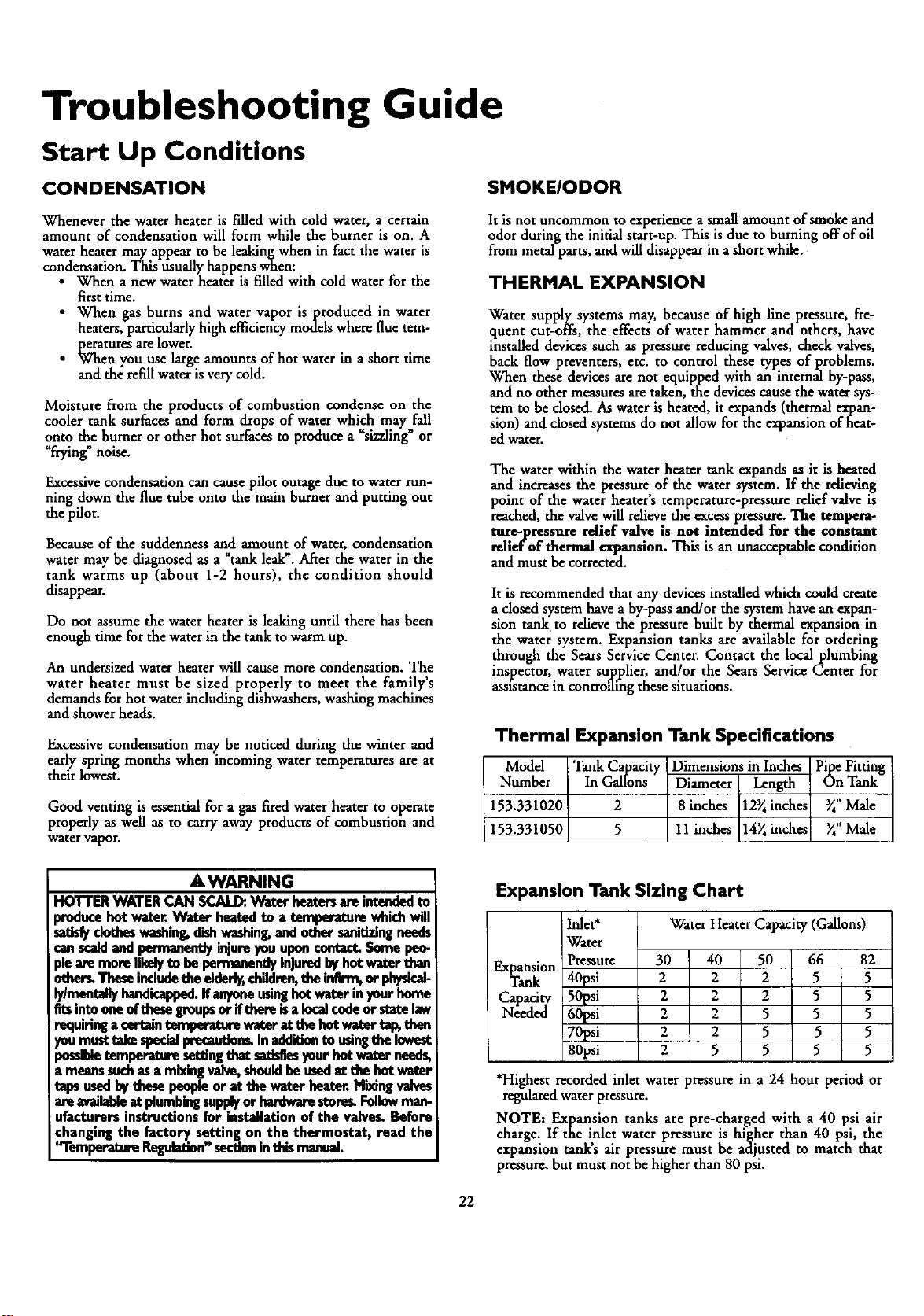
Troubleshooting Guide
Start Up Conditions
CONDENSATION SMOKEIODOR
Whenever the water heater is filled with cold water, a certain
amount of condensation will form while the burner is on. A
water heater may appear to be leakingwhen in fact the water is
condensation. This usually happens when:
•When anew water heater is filled with cold water for the
first time.
• When gas burns and water vapor is produced in water
heaters, particularly high efficiency models where flue tem-
peratures are lower.
•When you use large amounts of hot water in a short time
and the refillwater is very cold.
Moisture from the products of combustion condense on the
cooler tank surfaces and form drops of water which may fall
onto the burner or other hot surfaces to produce a %izaling_ or
"frying" noise.
Excessivecondensation can cause pilot outage due to water run-
ning down the flue tube onto the main burner and putting out
the pilot.
Because of the suddenness and amount of water, condensation
water may be diagnosed as a"tankleak_. After the water in the
tank warms up (about 1-2 hours), the condition should
disappear.
Do not assume the water heater is leaking until there has been
enough time for the water in the tank to warm up.
An undersized water heater will cause more condensation. The
water heater must be sized properly to meet the family's
demands for hot water including dishwashers, washing machines
and shower heads.
Excessive condensation may be noticed during the winter and
early spring months when incoming water temperatures are at
their lowest.
Good venting is essential for a gas fired water heater to operate
properly as well as to carry away products of combustion and
water vapor.
It is not uncommon to experience a small amount of smoke and
odor during the initial start-up. This is due to burning off of oil
from metal parts, and will disappear in a short while.
THERMAL EXPANSION
Water supply systems may, because of high line pressure, fre-
quent cut-offs, the effects of water hammer and others, have
installed devices such as pressure reducing valves, check valves,
back flow preventers, etc. to control these types of problems.
When these devices are not equipped with an internal by-pass,
and no other measuresare taken, the devices cause the water sys-
tem to be closed. As water is heated, it expands (thermal expan-
sion) and dosed systems do not allow for the expansion of heat-
ed water.
The water within the water heater tank expands as it is heated
and increases the pressure, of the water system. If the relieving
point of the water heater s temperature-pzessure relief valve is
reached, the valvewill relieve the excess pressure. The tcmpeea-
ture-pressure rdief valve is not intended for the constant
relief'of thermal expansion. This is an unacceptable condition
and must be corrected.
It is recommended that any devices installed which could create
adosed system have a by-pass and/or the system have an expan-
sion tank to rdieve the pressure built by thermal expansion in
the water system. Expansion tanks are available for ordering
through the Sears Service Center. Contact the local plumbing
inspector, water supplier, and/or the Sears Service Center for
assistance in controlling these situations.
Thermal Expansion Tank Specifications
Model Tank Capacity Dimensions in Inches Pipe Fitting
Number In Gallons Diameter Length On Tank
153.331020 2 8inches 12_inche2 _"Male
153.331050 5 11 inches 14_inche* _" Male
AWARNING
HOTTER WATER CAN SCALD:. Water heaters are intended to
produce hot water.Water heated to atemperetu.re which will
satisfyclotheswashmg, dishwashing,and other sanitizingneeds
can scald and permanonfly injure yon upon contact. Some pon-
Ceare more likelyto be permanently injuredby hot water than
other_ These includethe elderl_ childron, the ingrm, or ph_ic_
ly/mentally handicapped.If anyoneusinghot water in your home
fitsinto one ofthesegreupsor ifthere is a lucal€ode or state law
requiringa retrain temperaU_ water at the hot water tap, then
_)umusttake specialprecauttor-_In addition to usingthe Ioweat
a)ssibletempemtore setting that satisfiesyour hot water needs,
a means suchasa mi_ng valve, shouldbe usedat the hot water
taps usedby thesu people or at the water heaten.M_ng valves
are availableat plumbingsupplyor hardwarestore_ Followman-
ufacturers instructions for installation of the valves. Before
changing the factory setting on the thermostat, read the
'fl'emperature Regulation"sectionin this manual.
Expansion Tank Sizing Chart
Water Heater Capacity (Gallons)
Inlet*
Water
Pressure
40psi
50psi
60psi
70psi
80psi
Expansion 30 40 50 66 82
Tank 2 2 25 5
Capacity 2 2 2 5 5
Needed 2 2 5 5 5
2 2 5 5 5
25 5 5 5
*Highest recorded inlet water pressure in a 24 hour period or
regulated water pressure.
NOTE: Expansion tanks are pre-charged with a 40 psi air
charge. If the inlet water pressure is higher than 40 psi, the
expansion tanks air pressure must be adjusted to match that
pressure, but must not be higher than 80 psi.
22
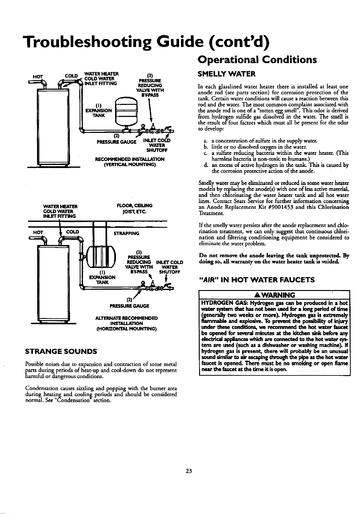
Troubleshooting Guide (cont'd)
Operational Conditions
HOT COLD WATERHEATER O)
•COLD WATER PRESSURE
rINLET FITTING REDUCING
VALVEWITH
BY-PASS
0) 1
EXPANSION
TANK
(2)
PRESSUREGAUGE WATER
SHUTOFF
RECOMMENDED INSTALLATION
(WRnCALMOUNnNG)
SMELLY WATER
In each glasslined water heater there is installed at least one
anode rod (see parts section) for corrosion protection of the
tank. Certain waterconditions will cause a reaction between this
rod and the water. The most common complaint associated with
the anode rod isone ofa _rotten egg smell". This odor is derived
from hydrogen sulfide gas dissolved in the water. The smell is
the result of four factors which must all be present for the odor
to develop:
a. aconcentration of sulfate in the supply water.
b. little orno dissolvedoxygen in the water.
c. a sulfate reducing bacteria within the water heater. (This
harmless bacteria is non-toxic to humans.)
d. an excessof active hydrogen in the tank. This is caused by
the corrosion protective action of the anode.
WATER HEATER
COLD WATER
INLET FITTING
HOT COLD
O)
EXPANSION
FLOOR,CEIUNG
jols'l; ETC.
STRAPPING
o)
PRESSURE
REDUCING INLET COLD
VALVEWITH WATER
BY-PASS SHUTOFF
Smellywater may be diminated orreducedin some water heater
models by replacingthe anode(s) with one of less active material,
and then chlorinating the water heater tank and all hot water
lines. Contact Sears Service for Furtherinformation concerning
an Anode Replacement Kit #9001453 and this Chlorination
Treatment.
If the smelly water persists after the anode replacementand chlo-
rination treatment, we can only suggest that continuous chlori-
nation and filtering conditioning equipment be considered to
eliminate the water problem.
Do not remove the anode leaving the tank unprotected. By
doing so, all warranty on the water heater tank is voided.
"AIR" IN HOT WATER FAUCETS
PRESSUREGAUGE
ALTERNATE RECOMMENDED
INSTALLATION
(HORIZONTAL MOUNTING)
STRANGE SOUNDS
Possible noises due to expansion and contraction of some metal
parts during periods of heat-up and cool-down do not represent
harmFul ordangerousconditions.
AWARNING
HYDROGEN GAS:Hydrogengascanbe producedin a hot
watersystemthet hasnetbeenreedfor a longperledof_rne
(generally two weeks .or more). Hydrogen gas is extremely
flammable and expiosve. To prevent the possibility of injury
under these conditions,we recommend the hot weter faucet
be opened for several minutes at the kitchen sink before any
electricalapplianceswhichare€onnectedto thehotwaters_-
tern are used (such as adishwasher or washing machine). If
hydrogen gas is present, there will probably be an unusual
soundsimilar to air escapingthrough the pipe as the hot water
faucet is opened. There must be no smoking or open flame
near the faucetat the time it isopen.
Condensation causes sizzling and popping with the burner area
during heatin_ and coolin_ periods and should be considered
normal. See Condensation section.
23
Troubleshooting Guide (cont'd)
Operational Conditions (cont'd)
HIGH TEMPERATURE SHUT OFF SYSTEM WATER IS TOO HOT
This water heater is equipped with an automatic gas shut offsys-
tern. The high temperature shut off is built into the gas control
valve. This system shuts off the gas supply to the water heater
burners when high water temperatures are present. It is non-
resettable.If the high temperature shut off activates, the gascon-
trol valve must be rephced. If this were to occur, turn _OPP" the
entire gas supply to the water heater. Contact the Sears Service
Center.
AWARNING
Shouldoverheatingoccuror the gassupplyfail to shut off,
tom "OFF" the manualgascontrol valveto the appliance.
NOT ENOUGH OR NO HOT WATER
•Check the manualgasshut off valveto be sure it is open.
•Check the pilot flame. It mayhave gone out. All models have
an opening behind the outerdoor for viewing the pilot.
•If the pilot is not lit, follow the _Lighting_ instructions in this
manual or located above the gas control valve on the water
heater to rdight the pilot. If the water was extremdy hot and is
now cold, the high limit safety temperature shut off mayhave
put out the burner and pilot. If the high temperature shut off
activates, the gascontrolvalve must be replaced. Contact the
SearsServiceCenter.
• The gascontrol knob must be turned to the "ON" position.
• The temperature adjustment dial may be set too low. See the
_Temperature Regulation_section.
• The gascompany can check the gasinput to see if it is correct.
An underfired water heater will not heat water as quickly.
•Look for leaking or open hot water faucets. Make sure all axe
dosed.
• The cold water inlet temperature may be colder during the
winter months. It will take longerto heat the water and seem
like lesshot water.
• If you cannot find what is wrong, call the SearsService Center.
•The temperature adjustment dial may be set too high. See the
Tempe.rature Adjnstment section.
NOTE: A period of time is necessary after an adjustment
has been made for the water temperature to reach the new
temperature setting.
•Iflowertempetature sertin_ will not lowerthe water tempera-
ture, call the SearsService x..enter.
AWARNING
Due to the nature of the typical gaswater heater, the
water temperature in certain situations may be hotter
than the thermostat setting.
Sho.r_ frequent draws of hot water - especiallywith very
coldincomingwater - canshockthe thermostat Into brief
operation resulting in hotter and hotter layers of water
closer to the top of the tank.
Changes in hot water usage patterns or raising the tem-
peratura differential between the cut_..n of the thermo-
stot and the cold water temperature _qll usually eliminate
the problem.
24
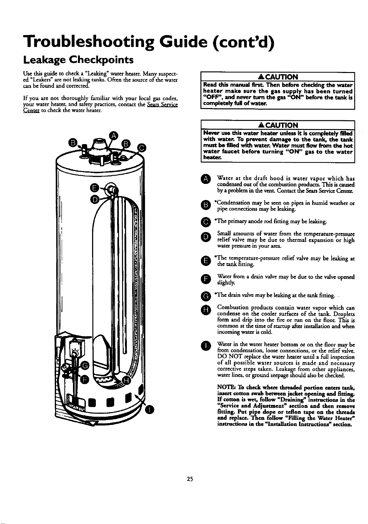
Troubleshooting Guide (cont'd)
Leakage Checkpoints
Use this guide to check a "Leaking"water heater. Many suspect-
ed =Leakers" are not leaking tanks. Often the source of the water
can be found and corrected.
If you are not thoroughly familiar with your local gas codes,
your water heater, and _tafetypractices, contact the
Center m check the water heater.
ACAUTION
Read this manual first. Then before checldng the water
heater make sure the gas supply has been turned
"OFF", and never turn the gas"ON" before the tank is[
completely fullof water. I
ACAUTION [
Never usethis water heater unlessit iscompletely filled [
with water. To prevent damage to the tank, the tank
must befilled with water. Water must flow from the hot
water faucet before turning "ON" gas to the water[
heater. [
OWater at the draft hood is water vapor which has
condensed out of the combustion products. This is caused
by a problem in the vent. Contact the Sears ServiceCenter.
O*Condensation may be seen on pipes in humid weather or
pipe connections may be leaking.
O'The primary anode rodfitting maybe leaking.
O Small amounts of water from the temperature-pressure
relief valve may be due to thermal expansion or high
water pressure in your area.
*The temperature-pressure relief valve may be leaking at
the tank fitting.
Water from a drain valvemay be due to the valve owned
slightly.
*The drainvalvemay be leaking at the tank fitting.
Combustion products contain water vapor which can
condense on the cooler surfaces of the tank. Droplets
form and drip into the fire or run on the floor. This is
common at the '_imeof startup after instalhtion and when
incoming water is cold.
Water in the waterheater bottom or on the floor maybe
from condensation, loose connections, or the rdief valve.
DO NOT replace the water heater until a flail inspection
of all possible water sources is made and necessary
corrective steps taken. Leakage from other appliances,
water lines, or ground seepage should also be checked.
NOTE: To check where threaded portion enters tank,
insert cotton swab between j.ac_._ Ol_nmg .andtitting,
If cov..on is wet, ..follow"Draining" mstrucuons in the
_Serwce and Adjustment _ section and then remove
fitting. Put pipe dope or teflon tape on the threads
and replace. Then follow "Fdllng the Water Heate_'
instructions in the"Installation Instructions_ section.
25
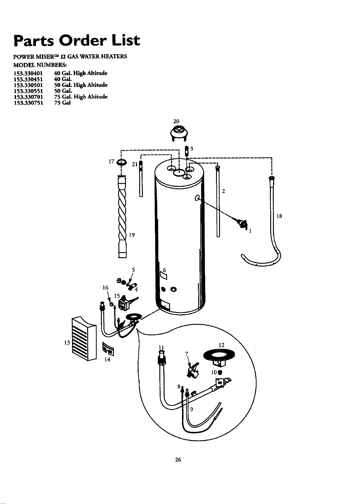
Parts Order List
POWER MISER TM 12 GAS WATER HEATERS
MODEL NUMBERS:
153.330401
153.330451
153.330501
153.330551
153.330701
153.330751
40 Gal. High Altitude
40 Gal.
50 Gal. High Altitude
50 Gal.
75 Gal. High Altitude
75 Gal
2O
17_ 2In
19
18
11 7
8_ 10_
26
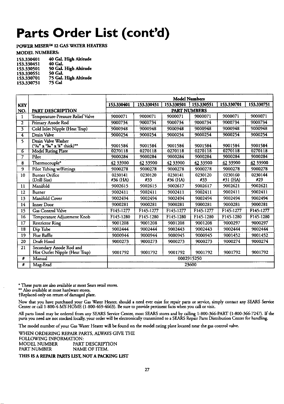
Parts Order List (cont'd)
POWER MISER TM 12 GAS WATER HEATERS
MODEL NUMBERS:
153.330401 40 Gal. High Altlmde
153.330451 40 Gal.
153.330501 50 Gal. High Altitude
153.330551 50 Gal.
153.330701 75 Gal. High Altitude
153.330751 75 Gal
KEY
NO.
1
2
3
4
5
6
7
8
9
10
11
12
13
!4
15
16
17
18
19
20
21
153.330401 153330451 153.330701 153.330751
PART DESCRIPTION
Temperature-Pressure Relief Valve
Primary Anode Rod
Cold Inlet Nipple (Heat Trap)
Drain Valve
Drain Valve Washer
(_" • 'Y-"• Wthick)**
Model Rating Plate
Pilot
Thermocouple*
Pilot Tubing w/Fittin_s
Burner Orifice
(Drill Size)
Manifold
Burner
Manifold Cover
Inner Door
Gas Control Valve
Temperature Adjustment Knob
Restrictor Ring
Dip Tube
Flue Baffle
Draft Hood
Secondary Anode Rod and
Hot Outlet Nipple (Heat Trap)
Manual
Mag-Erad
9000071
9000734
9000948
9000254
9001584
0270118
9000284
4233900
9000278
0230141
#36 (HA)
9002615
9002411
9002494
9000281
F145-1277
F145-1280
9001208
9002444
9000944
9000273
9000071
9000734
9000948
9000254
9001584
0270118
9000284
4233900
9000278
0230120
#33
9002615
9002411
9002494
9000281
F145-1277
F145-1280
9001208
9002444
9000944
9000273
9000071
9000734
9000948
9000254
Model Numbers
153.330501 153.330551
PART NUMBERS
9000071 9000071
9000734 9000734
9000948 9000948
9000254 9000254
9001584 9001584
0270118 0270118
9000284 9000284
4233900 4233900
9000278 9000278
0230141 0230120
#36 (HA) #33
9002617 9002617
9002411 900241I
9002494 9002494
9000281 9000281
F145-1277 F145-1277
F145-1280 F145-1280
9001208 9001208
9002443 9002443
9000945 9000945
9000273 9000273
9001792 9001792
0002915250
23600
9001584
0270118
9000284
4233900
9000278
0230160
#31 (HA)
9002621
9002411
9002494
9000281
F145-1277
F145-1280
9000297
9002444
9001452
9000274
9000071
9000734
9000948
9000254
9001584
0270118
9000284
42 33900
9000278
0230144
#29
9002621
9002411
9002494
9000281
F145-1277
F145-1280
9000297
9002444
9001452
9000274
9001792 9001792 9001792 9001792
#
#
*These parts are also available at most Sears retail stores.
**Also available at most hardware stores.
°fReplaced only on return of damaged plate.
Now that you have purchased your Gas Water Heater, should aneed ever exist for repair parts or service, simply contact any SEARS Service
Center or call 1-800-4-MY-HOME (1-800-4694663). Be sure to provide pertinent facts when you call or visit.
All parts listed may be ordered from any SEARS Service Center, most SEARS stores and by calling 1-800-366-PART (1-800-366-7247). If the
parts you need are not stocked locally, your order will be electronically transmitted to a SEARS Repair Parts Distribution Center for handling.
The model number of your Gas Water Heater will be found on the model rating plate located near the gas control valve.
WHEN ORDERING REPAIR PARTS, ALWAYS GIVE THE
FOLLOWING INFORMATION:
MODEL NUMBER PART DESCRIPTION
PART NUMBER NAME OF ITEM.
THIS lS AREPAIR PARTS LIST, NOT A PACKING LIST
27
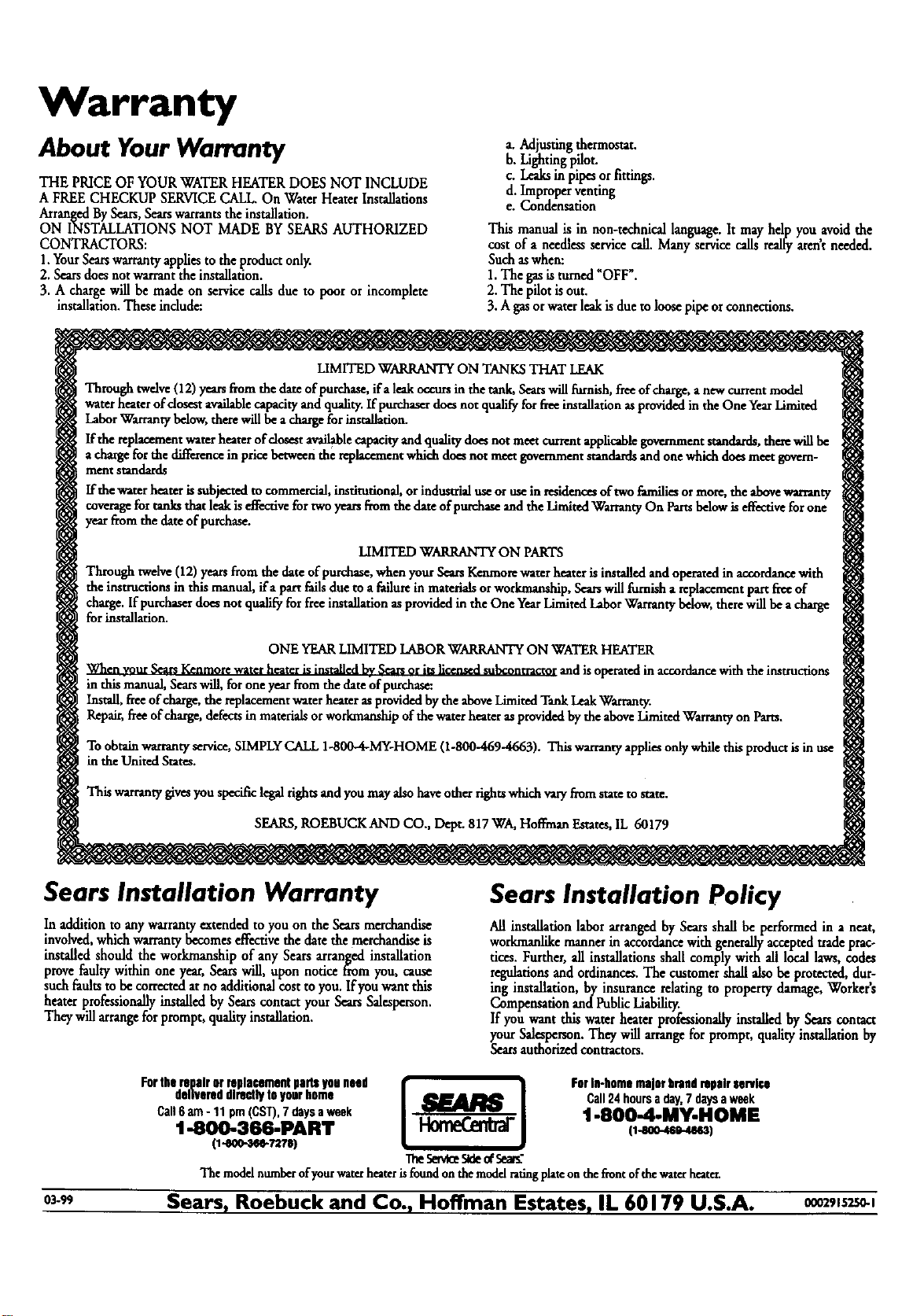
Warranty
About Your Warranty
THE PRICEOF YOURWATERHEATERDOES NOT INCLUDE
A FREE CHECKUP SERVICECALL.On Water HeaterInstallations
ArrangedBySears,Searswarrantsthe installation.
ON INSTALLATIONS NOT MADE BYSEARSAUTHORIZED
CONTRACTORS:
1.YourSearswarrantyappliesto the product only.
2. Searsdoesnotwarrantthe installation.
3. A chargewill be made on servicecalls due to poor or incomplete
installation.Theseindude:
a. Adjustingthermostat.
b. Lightingpilot.
c. Leaksinpipesorfittings.
d. Improperventing
e. Condensation
This manual is in non-technicallanguage.It mayhelp you avoid the
cost of a needlessservicecall. Manyservicecallsreallyarent needed.
Suchaswhen:
1.The gasisturned _OFF°.
2. Thepilot isout.
3. Agasorwaterleakisdueto loosepipeorconnections.
LIMITED WARRANTYON TANKSTHAT LEAK
Through twelve(12)yearsfromthe damofpurchase,ifaleakoccursin thetank, Searswillfurnish,freeofcharge,a newcurrentmodel
waterheaterofclosestavailablecapacityand quality.Ifpurchaserdoesnot qualifyforfreeinstallationasprovidedintheOne YearLimited
LaborWarrantybelow,therewillbeadmrgeforinstallation.
Ifthe replaceanentwaterheater ofclosestavailablecapacityand qualitydoesnor meetcurrentapplicablegovernmentstandards,thesewillbe
achargeforthe differencein pricebetweenthe replacementwhichdoesnot meetgovernmentstandardsandonewhichdoesmeetgovern-
meritstandards
If thewaterheaterissubjectedm commercial,institutional,orindustrialuseoruseinresidencesoftwo familiesormore,the abovewarranty
coveragefor tanksthat leakiseffectivefortwoyearsfromthe dateofpurchaseand theLimitedWarrantyOn Partsbelowiseffectivefor one
yearfromthe dateofpurchase.
LIMITEDWARRANTYON PARTS
htwelve(12)yearsfrom the dateofpurchase,whenyourS_arsKenmorewater heaterisinstalledand operatedin accordancewith
the instructionsinthis raznual,ifa part failsdueto afailurein materialsorworkmanship,Searswillfurnisha rephcementpartfreeof
charge.If purchaserdoesnotqualifyfor freeinstallationasprovidedin the One YearLimitedLaborWarrantybdow,therewillbeacharge
forinstallation.
ONEYEARLIMITEDLABORWARRANTYON WATERHEATER
When yourSearsKenmorewaterheaterisinstalledbySearsorits llc_am_clsubcontrac_¢iandis operatedin accordancewiththe instructions
in thismanual,Searswill,foroneyearfromthe dateofpurchase:
Install,f_e of charge,the replacementwaterheaterasprovidedbytheaboveLimitedTankLeakWarranty.
Repair,freeofcharge,defectsin materialsorworkmanshipofthe waterheateras providedbythe aboveLimitedWarrantyon Parts.
Toobtainwarrantyservice,SIMPLYCALL1-800-4-MY-HOME(1-800--469-4663).Thiswarrantyappliesonlywhilethisproductisin use
in the UnitedStates.
Thiswarrantygivesyouspecificlegaltights andyoumayalsohaveothertightswhichva_ from stateto state.
SEARS,ROEBUCKAND CO., Dept. 817WA,HoffmanEstates,IL 60179
Sears Installation Warranty
In additionto anywarranty extendedto you on the Searsmerchandise
involved,whichwarrantybecomeseffectivethe datethe merchandiseis
installedshould the workmanship of any Searsarranged installation
provefaultywithin one year,Searswill, upon notice fromyou, cause
suchfaultsto be correctedatno additionalcostto you.Ifyou want this
heater professionallyinstalledby Searscontact your SearsSalesperson.
Theywill arrangeforprompt, qualityinstallation.
Sears Installation Policy
All installationlabor arrangedby Searsshall be performed in a neat,
workmanlikemannerin accordancewith generallyacceptedtradeprac-
tices. Further, all installationsshall complywith all local laws,codes
regulationsand ordinances.The customer shallalsobe protected,dur-
ing installation, by insurance relatingto property damage,Workers
Compensationand PublicLiability.
If you want this water heaterpmfeasionallyinstalled by Sears contact
your Salesperson.Theywillarrangefor pmmpt, qualityinstallationby
Searsauthorizedcontractors.
delivereddirectlytoyourhomo Call24hoursaday,7daysaweek
Call6am- 11pm(CST),7daysaweek 1-8004-MY-HOME
1-800-366-PART (1-8oo.469.4863)
(t-aoo-,_e-Tua) TheSen_S_ ofSe_"
Themodelntunberof)ourwaterheaterisfoundonthemodelratingplateonthefrontof thewaterheater.
03._ Sears, Roebuck and Co., Hoffman Estates, IL 60179 U.S.A. 00om,szs0-1