INSTRUCTION MANUAL
MANUAL DE INSTRUCCIONES
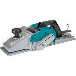
Cordless Planer
Cepillo Inalámbrico
GPK01
IMPORTANT: Read Before Using.
IMPORTANTE: Lea antes de usar.

2 ENGLISH
ENGLISH (Original instructions)
SPECIFICATIONS
Model: GPK01
Planing width 82 mm (3-1/4")
Planing depth 4 mm (5/32")
Shiplapping depth 25 mm (1")
No load speed 15,000 /min
Overall length (with BL4040) 385 mm (15-1/8")
Rated voltage D.C. 36 V - 40 V max
Net weight 3.7 - 4.9 kg (8.2 - 10.8 lbs)
• Duetoourcontinuingprogramofresearchanddevelopment,thespecicationshereinaresubjecttochange
without notice.
• Specicationsandbatterycartridgemaydierfromcountrytocountry.
• Theweightmaydierdependingontheattachment(s),includingthebatterycartridge.Thelightestandheavi-
est combinations, according to EPTA-Procedure 01/2014, are shown in the table.
Applicable battery cartridge and charger
Batterycartridge BL4020* / BL4025* / BL4040* / BL4050F
*:Recommendedbattery
Charger DC40RA / DC40RB / DC40RC
• Someofthebatterycartridgesandchargerslistedabovemaynotbeavailabledependingonyourregionof
residence.
WARNING: Only use the battery cartridges and chargers listed above.Useofanyotherbatterycartridges
andchargersmaycauseinjuryand/orre.
SAFETY WARNINGS
General power tool safety warnings
WARNING: Read all safety warnings, instruc-
tions, illustrations and specications provided
with this power tool. Failure to follow all instructions
listedbelowmayresultinelectricshock,reand/or
seriousinjury.
Save all warnings and instruc-
tions for future reference.
Theterm"powertool"inthewarningsreferstoyour
mains-operated(corded)powertoolorbattery-operated
(cordless) power tool.
Work area safety
1. Keep work area clean and well lit. Cluttered or
dark areas invite accidents.
2. Do not operate power tools in explosive atmo-
spheres, such as in the presence of ammable
liquids, gases or dust. Power tools create sparks
whichmayignitethedustorfumes.
3. Keep children and bystanders away while
operating a power tool. Distractions can cause
youtolosecontrol.
Electrical Safety
1.
Power tool plugs must match the outlet. Never modify
the plug in any way. Do not use any adapter plugs
with earthed (grounded) power tools. Unmodiedplugs
and matching outlets will reduce risk of electric shock.
2. Avoid body contact with earthed or grounded
surfaces, such as pipes, radiators, ranges and
refrigerators. There is an increased risk of elec-
tricshockifyourbodyisearthedorgrounded.
3. Do not expose power tools to rain or wet con-
ditions. Water entering a power tool will increase
the risk of electric shock.
4. Do not abuse the cord. Never use the cord for
carrying, pulling or unplugging the power tool.
Keep cord away from heat, oil, sharp edges
or moving parts. Damaged or entangled cords
increase the risk of electric shock.
5.
When operating a power tool outdoors, use an
extension cord suitable for outdoor use. Use of a cord
suitable for outdoor use reduces the risk of electric shock.
6. If operating a power tool in a damp location is
unavoidable, use a ground fault circuit inter-
rupter (GFCI) protected supply. Use of a GFCI
reduces the risk of electric shock.
7.
Power tools can produce electromagnetic elds
(EMF) that are not harmful to the user. However,
users of pacemakers and other similar medical
devices should contact the maker of their device and/
or doctor for advice before operating this power tool.

3 ENGLISH
Personal Safety
1. Stay alert, watch what you are doing and use
common sense when operating a power tool.
Do not use a power tool while you are tired or
under the inuence of drugs, alcohol or med-
ication. A moment of inattention while operating
powertoolsmayresultinseriouspersonalinjury.
2. Use personal protective equipment. Always
wear eye protection. Protective equipment such
asdustmask,non-skidsafetyshoes,hardhat,or
hearing protection used for appropriate conditions
willreducepersonalinjuries.
3. Prevent unintentional starting. Ensure the
switch is in the o-position before connecting
to power source and/or battery pack, picking
up or carrying the tool.Carryingpowertoolswith
yourngerontheswitchorenergisingpowertools
that have the switch on invites accidents.
4. Remove any adjusting key or wrench before
turning the power tool on.Awrenchorakeyleft
attachedtoarotatingpartofthepowertoolmay
resultinpersonalinjury.
5. Do not overreach. Keep proper footing and
balance at all times. This enables better control
of the power tool in unexpected situations.
6. Dress properly. Do not wear loose clothing or
jewellery. Keep your hair, clothing and gloves
away from moving parts.Looseclothes,jewel-
leryorlonghaircanbecaughtinmovingparts.
7. If devices are provided for the connection of
dust extraction and collection facilities, ensure
these are connected and properly used. Use of
dust collection can reduce dust-related hazards.
8. Do not let familiarity gained from frequent use
of tools allow you to become complacent and
ignore tool safety principles. A careless action
cancausesevereinjurywithinafractionofa
second.
9.
Always wear protective goggles to protect your
eyes from injury when using power tools. The
goggles must comply with ANSI Z87.1 in the USA.
It is an employer's responsibility to enforce the
use of appropriate safety protective equipment
by the tool operators and by other persons in
the immediate working area.
Power tool use and care
1. Do not force the power tool. Use the correct
power tool for your application. The correct
powertoolwilldothejobbetterandsaferatthe
rate for which it was designed.
2. Do not use the power tool if the switch does
not turn it on and o.Anypowertoolthatcannot
be controlled with the switch is dangerous and
must be repaired.
3. Disconnect the plug from the power source
and/or remove the battery pack, if detachable,
from the power tool before making any adjust-
ments, changing accessories, or storing power
tools.Suchpreventivesafetymeasuresreduce
theriskofstartingthepowertoolaccidentally.
4. Store idle power tools out of the reach of chil-
dren and do not allow persons unfamiliar with
the power tool or these instructions to operate
the power tool. Power tools are dangerous in the
hands of untrained users.
5.
Maintain power tools and accessories. Check for
misalignment or binding of moving parts, break-
age of parts and any other condition that may
aect the power tool’s operation. If damaged, have
the power tool repaired before use.Manyaccidents
arecausedbypoorlymaintainedpowertools.
6. Keep cutting tools sharp and clean.Properly
maintained cutting tools with sharp cutting edges
arelesslikelytobindandareeasiertocontrol.
7. Use the power tool, accessories and tool bits
etc. in accordance with these instructions, tak-
ing into account the working conditions and
the work to be performed. Use of the power tool
foroperationsdierentfromthoseintendedcould
result in a hazardous situation.
8.
Keep handles and grasping surfaces dry, clean
and free from oil and grease.Slipperyhandlesand
grasping surfaces do not allow for safe handling and
control of the tool in unexpected situations.
9. When using the tool, do not wear cloth work
gloves which may be entangled. The entangle-
mentofclothworkglovesinthemovingpartsmay
resultinpersonalinjury.
Battery tool use and care
1. Recharge only with the charger specied by
the manufacturer. A charger that is suitable for
onetypeofbatterypackmaycreateariskofre
whenusedwithanotherbatterypack.
2. Use power tools only with specically desig-
nated battery packs.Useofanyotherbattery
packsmaycreateariskofinjuryandre.
3. When battery pack is not in use, keep it away
from other metal objects, like paper clips,
coins, keys, nails, screws or other small metal
objects, that can make a connection from one
terminal to another.Shortingthebatterytermi-
nalstogethermaycauseburnsorare.
4. Under abusive conditions, liquid may be
ejected from the battery; avoid contact. If con-
tact accidentally occurs, ush with water. If
liquid contacts eyes, additionally seek medical
help.Liquidejectedfromthebatterymaycause
irritation or burns.
5. Do not use a battery pack or tool that is dam-
aged or modied.Damagedormodiedbatteries
mayexhibitunpredictablebehaviourresultingin
re,explosionorriskofinjury.
6. Do not expose a battery pack or tool to re or
excessive temperature.Exposuretoreortem-
peratureabove130°Cmaycauseexplosion.
7. Follow all charging instructions and do not
charge the battery pack or tool outside the
temperature range specied in the instruc-
tions.Chargingimproperlyorattemperatures
outsidethespeciedrangemaydamagethe
batteryandincreasetheriskofre.
Service
1. Have your power tool serviced by a qualied
repair person using only identical replacement
parts.Thiswillensurethatthesafetyofthepower
tool is maintained.
2. Never service damaged battery packs. Service
ofbatterypacksshouldonlybeperformedbythe
manufacturer or authorized service providers.

4 ENGLISH
3. Follow instruction for lubricating and chang-
ing accessories.
4. Do not modify or attempt to repair the appli-
ance or the battery pack except as indicated in
the instructions for use and care.
Cordless Planer Safety Warnings
1. Wait for the cutter to stop before setting the
tool down.Anexposedrotatingcuttermay
engage the surface leading to possible loss of
controlandseriousinjury.
2. Use clamps or another practical way to secure
and support the workpiece to a stable plat-
form.Holdingtheworkpiecebyyourhandor
againstthebodyleavesitunstableandmaylead
to loss of control.
3. Rags, cloth, cord, string and the like should
never be left around the work area.
4. Avoid cutting nails. Inspect for and remove all
nails from the workpiece before operation.
5. Use only sharp blades. Handle the blades very
carefully.
6. Be sure the blade installation bolts are
securely tightened before operation.
7. Hold the tool rmly with both hands.
8. Keep hands away from rotating parts.
9. Before using the tool on an actual workpiece,
let it run for a while. Watch for vibration or
wobbling that could indicate poor installation
or a poorly balanced blade.
10. Make sure the blade is not contacting the
workpiece before the switch is turned on.
11. Wait until the blade attains full speed before
cutting.
12. Always switch o and wait for the blades to
come to a complete stop before adjusting
depth of cut.
13. Never stick your nger into the chip chute.
Chute may jam when cutting damp wood.
Clean out chips with a stick.
14. Do not leave the tool running. Operate the tool
only when hand-held.
15.
When replace the blades or some parts on the
drum, make sure to replace the parts on both
sides of the drum as a set. Otherwise, the resulting
imbalance will cause vibration and shorten tool life.
16. Use only Makita blades specied in this
manual.
17. Always use the correct dust mask/respirator
for the material and application you are work-
ing with.
18. Operate the tool on stable condition. Operation
onunstableconditionmaycauseadamageinjury.
SAVE THESE INSTRUCTIONS.
WARNING: DO NOT let comfort or familiarity
with product (gained from repeated use) replace
strict adherence to safety rules for the subject
product.
MISUSE or failure to follow the safety rules stated
in this instruction manual may cause serious
personal injury.
Symbols
Thefollowingsshowthesymbolsusedfortool.
volts
direct current
no load speed
revolutions or reciprocation per minute
Important safety instructions for
battery cartridge
1.
Before using battery cartridge, read all instruc-
tions and cautionary markings on (1) battery char-
ger, (2) battery, and (3) product using battery.
2.
Do not disassemble or tamper with the battery car-
tridge.Itmayresultinare,excessiveheat,orexplosion.
3. If operating time has become excessively
shorter, stop operating immediately. It may
result in a risk of overheating, possible burns
and even an explosion.
4.
If electrolyte gets into your eyes, rinse them out
with clear water and seek medical attention right
away. It may result in loss of your eyesight.
5. Do not short the battery cartridge:
(1) Do not touch the terminals with any con-
ductive material.
(2) Avoid storing battery cartridge in a con-
tainer with other metal objects such as
nails, coins, etc.
(3) Do not expose battery cartridge to water
or rain.
A battery short can cause a large current
ow, overheating, possible burns and even a
breakdown.
6. Do not store and use the tool and battery car-
tridge in locations where the temperature may
reach or exceed 50 °C (122 °F).
7. Do not incinerate the battery cartridge even if
it is severely damaged or is completely worn
out. The battery cartridge can explode in a re.
8. Do not nail, cut, crush, throw, drop the battery
cartridge, or hit against a hard object to the
battery cartridge.Suchconductmayresultina
re,excessiveheat,orexplosion.
9. Do not use a damaged battery.
10.
The contained lithium-ion batteries are subject to
the Dangerous Goods Legislation requirements.
Forcommercialtransportse.g.bythirdparties,
forwarding agents, special requirement on pack-
aging and labeling must be observed.
For preparation of the item being shipped, consult-
ing an expert for hazardous material is required.
Pleasealsoobservepossiblymoredetailed
national regulations.
Tapeormaskoopencontactsandpackupthe
batteryinsuchamannerthatitcannotmove
around in the packaging.

5 ENGLISH
11.
When disposing the battery cartridge, remove it from
the tool and dispose of it in a safe place. Follow your
local regulations relating to disposal of battery.
12. Use the batteries only with the products
specied by Makita. Installing the batteries to
non-compliantproductsmayresultinare,exces-
siveheat,explosion,orleakofelectrolyte.
13. If the tool is not used for a long period of time,
the battery must be removed from the tool.
14. During and after use, the battery cartridge may
take on heat which can cause burns or low
temperature burns. Pay attention to the han-
dling of hot battery cartridges.
15.
Do not touch the terminal of the tool immediately
after use as it may get hot enough to cause burns.
16. Do not allow chips, dust, or soil stuck into the
terminals, holes, and grooves of the battery
cartridge.Itmaycauseheating,catchingre,
burstandmalfunctionofthetoolorbatterycar-
tridge,resultinginburnsorpersonalinjury.
17. Unless the tool supports the use near
high-voltage electrical power lines, do not use
the battery cartridge near a high-voltage elec-
trical power lines.Itmayresultinamalfunction
orbreakdownofthetoolorbatterycartridge.
18. Keep the battery away from children.
SAVE THESE INSTRUCTIONS.
CAUTION: Only use genuine Makita batteries.
Use of non-genuine Makita batteries, or batteries that
havebeenaltered,mayresultinthebatterybursting
causingres,personalinjuryanddamage.Itwill
alsovoidtheMakitawarrantyfortheMakitatooland
charger.
Tips for maintaining maximum
battery life
1. Charge the battery cartridge before completely
discharged. Always stop tool operation and
charge the battery cartridge when you notice
less tool power.
2. Never recharge a fully charged battery car-
tridge. Overcharging shortens the battery
service life.
3.
Charge the battery cartridge with room tempera-
ture at 10 °C - 40 °C (50 °F - 104 °F). Let a hot
battery cartridge cool down before charging it.
4. When not using the battery cartridge, remove
it from the tool or the charger.
5. Charge the battery cartridge if you do not use
it for a long period (more than six months).
Important safety instructions for
wireless unit
1. Do not disassemble or tamper with the wire-
less unit.
2. Keep the wireless unit away from young chil-
dren. If accidentally swallowed, seek medical
attention immediately.
3. Use the wireless unit only with Makita tools.
4. Do not expose the wireless unit to rain or wet
conditions.
5. Do not use the wireless unit in places where
the temperature exceeds 50 °C (122 °F).
6. Do not operate the wireless unit in places
where medical instruments, such as heart
pace makers are nearby.
7. Do not operate the wireless unit in places
where automated devices are nearby. If oper-
ated,automateddevicesmaydevelopmalfunction
or error.
8. Do not operate the wireless unit in places
under high temperature or places where
static electricity or electrical noise could be
generated.
9.
The wireless unit can produce electromagnetic
elds (EMF) but they are not harmful to the user.
10. The wireless unit is an accurate instrument. Be
careful not to drop or strike the wireless unit.
11. Avoid touching the terminal of the wireless
unit with bare hands or metallic materials.
12. Always remove the battery on the product
when installing the wireless unit into it.
13. When opening the lid of the slot, avoid the
place where dust and water may come into the
slot. Always keep the inlet of the slot clean.
14. Always insert the wireless unit in the correct
direction.
15. Do not press the wireless activation button
on the wireless unit too hard and/or press the
button with an object with a sharp edge.
16. Always close the lid of the slot when
operating.
17.
Do not remove the wireless unit from the slot while
the power is being supplied to the tool. Doing so
maycauseamalfunctionofthewirelessunit.
18. Do not remove the sticker on the wireless unit.
19. Do not put any sticker on the wireless unit.
20. Do not leave the wireless unit in a place where
static electricity or electrical noise could be
generated.
21.
Do not leave the wireless unit in a place subject
to high heat, such as a car sitting in the sun.
22. Do not leave the wireless unit in a dusty or
powdery place or in a place corrosive gas
could be generated.
23. Sudden change of the temperature may bedew
the wireless unit. Do not use the wireless unit
until the dew is completely dried.
24. When cleaning the wireless unit, gently wipe
with a dry soft cloth. Do not use benzine, thin-
ner, conductive grease or the like.
25. When storing the wireless unit, keep it in the
supplied case or a static-free container.
26. Do not insert any devices other than Makita
wireless unit into the slot on the tool.
27. Do not use the tool with the lid of the slot dam-
aged.Water,dust,anddirtcomeintotheslotmay
cause malfunction.
28. Do not pull and/or twist the lid of the slot more
than necessary.Restorethelidifitcomeso
from the tool.
29. Replace the lid of the slot if it is lost or
damaged.
SAVE THESE INSTRUCTIONS.

6 ENGLISH
FUNCTIONAL
DESCRIPTION
CAUTION: Always be sure that the tool is
switched o and the battery cartridge is removed
before adjusting or checking function on the tool.
Installing or removing battery
cartridge
CAUTION: Always switch o the tool before
installing or removing of the battery cartridge.
CAUTION: Hold the tool and the battery car-
tridge rmly when installing or removing battery
cartridge.Failuretoholdthetoolandthebattery
cartridgermlymaycausethemtoslipoyourhands
andresultindamagetothetoolandbatterycartridge
andapersonalinjury.
1
2
3
1
Fig.1
►1. Red indicator 2. Button 3.Batterycartridge
Toremovethebatterycartridge,slideitfromthetool
while sliding the button on the front of the cartridge.
Toinstallthebatterycartridge,alignthetongueonthe
batterycartridgewiththegrooveinthehousingandslip
itintoplace.Insertitallthewayuntilitlocksinplace
withalittleclick.Ifyoucanseetheredindicatoras
showninthegure,itisnotlockedcompletely.
CAUTION: Always install the battery cartridge
fully until the red indicator cannot be seen. If not,
itmayaccidentallyfalloutofthetool,causinginjuryto
youorsomeonearoundyou.
CAUTION: Do not install the battery cartridge
forcibly.Ifthecartridgedoesnotslideineasily,itis
notbeinginsertedcorrectly.
Tool / battery protection system
Thetoolisequippedwithatool/batteryprotectionsys-
tem.Thissystemautomaticallycutsopowertothe
motortoextendtoolandbatterylife.Thetoolwillauto-
maticallystopduringoperationifthetoolorbatteryis
placed under one of the following conditions:
Overload protection
Whenthetool/batteryisoperatedinamannerthat
causesittodrawanabnormallyhighcurrent,thetool
automaticallystops.Inthissituation,turnthetoolo
and stop the application that caused the tool to become
overloaded. Then turn the tool on to restart.
Overheat protection
Whenthetool/batteryisoverheated,thetoolstops
automatically.Inthissituation,letthetool/batterycool
before turning the tool on again.
Overdischarge protection
Whenthebatterycapacityisnotenough,thetoolstops
automatically.Inthiscase,removethebatteryfromthe
toolandchargethebattery.
Protections against other causes
Protectionsystemisalsodesignedforothercauses
that could damage the tool and allows the tool to stop
automatically.Takeallthefollowingstepstoclearthe
causes,whenthetoolhasbeenbroughttoatemporary
halt or stop in operation.
1. Turnthetoolo,andthenturnitonagainto
restart.
2. Chargethebattery(ies)orreplaceit/themwith
rechargedbattery(ies).
3. Letthetoolandbattery(ies)cooldown.
Ifnoimprovementcanbefoundbyrestoringprotection
system,thencontactyourlocalMakitaServiceCenter.
Indicating the remaining battery
capacity
Pressthecheckbuttononthebatterycartridgetoindi-
catetheremainingbatterycapacity.Theindicatorlamps
light up for a few seconds.
1
2
Fig.2
►1. Indicator lamps 2. Check button

7 ENGLISH
Indicator lamps Remaining
capacity
Lighted O Blinking
75% to 100%
50% to 75%
25% to 50%
0% to 25%
Charge the
battery.
Thebattery
mayhave
malfunctioned.
NOTE: Depending on the conditions of use and the
ambienttemperature,theindicationmaydierslightly
fromtheactualcapacity.
NOTE:Therst(farleft)indicatorlampwillblinkwhen
thebatteryprotectionsystemworks.
Adjusting depth of cut
CAUTION: Always switch o and wait for the
blades to come to a complete stop before adjust-
ing depth of cut.
NOTE:Whenturningthedepthadjustmentknob,be
suretoholdthehandlermlywiththeotherhand.
Thecuttingdepthcanbeadjustedbyturningthedepth
adjustmentknobonthefrontofthetool.Turntheknob
toalignthepointerwithyourdesiredcuttingdepthon
the depth scale.
1
2
3
Fig.3
►1.Depthadjustmentknob2. Pointer 3. Depth scale
Switch action
WARNING: Before installing the battery car-
tridge into the tool, always check to see that the
switch trigger actuates properly and returns to
the "OFF" position when released.
WARNING: NEVER defeat the lock-o button
by taping down or some other means. A switch with
anegatedlock-obuttonmayresultinunintentional
operationandseriouspersonalinjury.
WARNING:
NEVER use the tool if it runs when you
simply pull the switch trigger without pressing the lock-o
button.Aswitchinneedofrepairmayresultinunintentional
operationandseriouspersonalinjury.ReturntooltoaMakita
service center for proper repairs BEFORE further usage.
NOTICE: Do not pull the switch trigger hard
without pressing in the lock-o button. This can
cause switch breakage.
Topreventtheswitchtriggerfrombeingaccidentally
pulled,thelock-obuttonisprovided.Tostartthetool,
depressandholdthelock-obutton,andthenpullthe
switch trigger. Release the switch trigger to stop.
1 2
Fig.4
►1. Switch trigger 2.Lock-obutton
Foot
Thefootspringsoutoftherearbasewhenyouliftthe
tool up from work surfaces to avoid the planer blades
touchingtheworkpiecedirectly.Itpreventstheplaner
blades from accidental damages when not in use.
Thefootspringsbackintotherearbasewheneveryou
place the tool base over work surfaces.
1 2 3 4
Fig.5
►
1. Planer blade 2. Rear base 3. Foot 4. Work surface

8 ENGLISH
Accidental restart preventive
function
Ifyouinstallthebatterycartridgewhilepullingthe
switch trigger, the tool does not start. To start the tool,
release the switch trigger, and then pull the switch trig-
geragainwhiledepressingthelock-obutton.
Electronic function
The tool is equipped with the following electronic func-
tionsforeasyoperation.
Electric brake
The tool is equipped with an electric brake. If the tool
consistentlyfailstoquicklystopafterreleasingthe
switchtrigger,havethetoolservicedatyourlocal
Makita Service Center.
Soft start feature
The soft-start function minimizes start-up shock, and
makesthetoolstartsmoothly.
ASSEMBLY
CAUTION: Always be sure that the tool is
switched o and the battery cartridge is removed
before carrying out any work on the tool.
Box wrench storage
When not in use, store the box wrench as shown in the
guretokeepitfrombeinglost.
1
Fig.6
►1. Box wrench
Removing and installing planer
blades
CAUTION: Tighten the blade installation bolts
carefully when attaching the planer blades to
the tool. Always check to see they are tightened
securely. A loose installation bolt can be dangerous.
CAUTION: Handle the planer blades very
carefully. Use gloves or rags to protect your n-
gers or hands when removing and installing the
planer blades.
CAUTION: Use only the Makita wrench pro-
vided to remove and install the planer blades.
Failuretodosomayresultinovertighteningorinsuf-
cienttighteningoftheinstallationbolts.Thiscould
causeaninjury.
NOTICE: To install planer blades, clean out all
chips or foreign matter adhering to the drum or
the planer blades. Use planer blades of the same
dimensions and weight, otherwise drum oscilla-
tion/vibration, causing poor planing action, and
tool breakdown will result.
For tool with conventional planer
blades
NOTE: A pair of planer blades are assembled in
the drum. Repeat the following procedures for each
planer blade.
Removing conventional planer blades
1. Unscrew the installation bolts from the drum using
the box wrench provided.
2. Disassemble the drum plate and conventional
planerblade(withadjustingplate)fromthedrum.
1
2
3
4
Fig.7
►1. Installation bolt 2. Drum plate 3. Conventional
planerblade(withadjustingplate)4. Drum

9 ENGLISH
3. Untighten the screws from the conventional planer
blade,andthenremovetheadjustingplate.
1
2
3
Fig.8
►1. Screws 2. Conventional planer blade 3.Adjusting
plate
Installing conventional planer blades
1. Set a conventional planer blade onto the blade
gauge, aligning its cutting edge along the guide wall on
thebladegaugehorizontally.
12
3
4
Fig.9
►1. Conventional planer blade 2. Blade gauge
3. Cutting edge 4. Guide wall
2. Placetheadjustingplateovertheconventional
planerblade,andthenslightlytightenthescrews.
3. Pushtheadjustingplateforwardsuntilitsposition-
ingguideneatlyandentirelytsalongtherearsidewall
of the blade gauge.
4. Holdtheadjustingplatewhereitisandtightenthe
screws to secure it in place.
1
3
2
4
5
6
Fig.10
►1.Adjustingplate2. Conventional planer blade
3. Screw 4. Positioning guide 5. Rear side wall
6. Blade gauge
5. Clean out all the wood chips and foreign matters
adhering to the drum and conventional planer blade.
6.
Slipthepositioningguideoftheadjustingplateinto
the guide groove in the drum, and then place the drum plate
overtheconventionalplanerblade(withadjustingplate).
7. Cross-tightenalltheinstallationboltsevenlywith
the box wrench.
1
2
3
4
5
6
7
Fig.11
►1. Positioning guide 2.Adjustingplate3. Guide
groove 4. Drum 5. Drum plate 6. Conventional
planer blade 7. Installation bolt

10 ENGLISH
For tool with mini planer blades
NOTE: A pair of planer blades are assembled in
the drum. Repeat the following procedures for each
planer blade.
Removing mini planer blades
1. Loosen the installation bolts one turn using the
box wrench provided.
2
1
Fig.12
►1. Installation bolt 2. Box wrench
2. Slidetheminiplanerbladeoutofthedrumby
pushing one end of the blade outwards from the belt
cover side.
1
2
4
3
Fig.13
►1. Mini planer blade 2. Drum 3. Belt cover 4.
T-handle of box wrench
NOTE: Use the ends of T-handle of the box wrench to
slide the mini planer blade out for safer operation and
maintenance.
Installing mini planer blades
1. Clean out all the wood chips and foreign matters
adhering to the drum and mini planer blade.
2. Slide a mini planer blade along between the drum
andsetplatebypushingoneendofthebladeinwards
from the side opposite to the belt cover.
3. Cross-tightenalltheinstallationboltsevenlywith
the box wrench.
1
3
2
4
6
5
Fig.14
►1. Mini planer blade 2. Drum 3. Set plate 4. Belt
cover 5. Installation bolt 6. Box wrench
Mini planer blade calibration
Perform a calibration on planner blades at regular inter-
valstooptimizeworkeciency.
1. Loosen the installation bolts one turn using the
box wrench provided.
2. Slidetheminiplanerbladeoutofthedrumby
pushing one end of the blade outwards from the belt
cover side.
3. Unscrew the installation bolts from the drum using
the box wrench.
4. Disassemble the drum plate and set plate (with
adjustingplate)fromthedrum.
1
2
3
4
Fig.15
►1. Installation bolt 2. Drum plate 3. Set plate (with
adjustingplate)4. Drum

11 ENGLISH
5. Loosen the screws on the set plate one turn to
disengagetheadjustingplate.
1
2
3
Fig.16
►1. Screws 2. Set plate 3.Adjustingplate
6. Clean out all the wood chips and foreign matters
adheringtothesetplate(withadjustingplate)andmini
planer blade.
7. Set the mini planer blade onto the blade gauge,
aligning its cutting edge along the guide wall on the
bladegaugehorizontally.
8. Placethesetplate(withadjustingplate)overthe
mini planer blade, aligning the guide ridges on the set
plate with guide grooves on the mini planer blade.
2
3
4
1
5
6
7
Fig.17
►1. Mini planer blade 2. Blade gauge 3. Cutting edge
4. Guide wall 5.Setplate(withadjustingplate)
6. Guide ridge 7. Guide groove
9. Pushtheadjustingplateforwardsuntilitsposition-
ingguideneatlyandentirelytsalongtherearsidewall
of the blade gauge.
10. Holdtheadjustingplatewhereitisandtightenthe
screws to secure it in place.
1
3
2
4
5
6
Fig.18
►1.Adjustingplate2. Set plate 3. Screw
4. Positioning guide 5. Rear side wall 6. Blade
gauge
11. Slipthepositioningguideoftheadjustingplate
into the guide groove in the drum, and then place the
drumplateoverthesetplate(withadjustingplate).
1
2
3
4
5
6
7
Fig.19
►1. Positioning guide 2.Adjustingplate3. Guide
groove 4. Drum 5. Drum plate 6. Set plate
7. Installation bolt

12 ENGLISH
12. Slightlytightentheinstallationbolts,andslidethe
mini planer blade along between the drum and set plate
bypushingoneendofthebladeinwardsfromtheside
opposite to the belt cover.
13. Cross-tightenalltheinstallationboltsevenlywith
the box wrench.
1
3
2
4
6
5
Fig.20
►1. Mini planer blade 2. Drum 3. Set plate 4. Belt
cover 5. Installation bolt 6. Box wrench

13 ENGLISH
Planer blade settings
Yourplaningsurfacewillenduproughanduneven,unlesstheplanerbladesaresetproperlyandsecurely.
Installplanerbladescorrectlysothecuttingedgessitinarightangle,onanabsolutelevelwiththerearbaseline,and
exactlyparalleltothesoleoftheplane.Readtheexamplesinthetableforpropersettings.
Planing surface Blade setting Cause
Correct setting
(A)
(B)
(C)
Cutting edges sit on a level with
the rear baseline and run side
to side parallel to the sole of
the plane.
Gouging at start
(A)
(B)
(C)
Cutting edges underreach the
rear baseline.
Gouging at end
(B)
(A)
(C)
Cutting edges overpass the
rear baseline.
Aslope in surface
(B)
(B)
(A)
(C)
Cutting edges sit side to side
unparalleled to the sole of the
plane.
(A):Frontbase(Adjustableshoe)
(B): Rear base (Fixed shoe)
(C): Planer blade
Installing guide rule
1.
Laythetooldownwiththebeltcoverfacingupwards.
2.
Mounttheguideruleinplacebysecuringitwiththe
thumb screw into the mounting hole on side of the tool head.
1
2
3
4
Fig.21
►
1. Belt cover 2. Guide rule 3. Thumb screw 4. Mounting hole
3. Slidetheedgefenceinandouttoyourdesired
planing width, and then tighten the thumb screw to
secure it in the required position.
1
2
Fig.22
►1. Edge fence 2. Thumb screw

14 ENGLISH
Installing depth guide
1. Laythetooldownwiththebeltcoverfacing
downwards.
2. Mountthedepthguideinplacebysecuringitwith
the washer and thumb screw into the mounting hole on
side of the tool head.
1
2
3
4
5
Fig.23
►1. Belt cover 2. Depth guide 3. Washer 4. Thumb
screw 5. Mounting hole
3. Slidethedepthguideupanddowntoyourdesired
planing depth, and then tighten the thumb screw to
secure it in the required position.
1
2
Fig.24
►1. Depth guide 2. Thumb screw
Installing chamfering rules
Optional accessory
1. Laythetooldownwiththefrontbasefacing
upwards.
2. Attach the edge fences to the mounting arms,
aligningtheprojectionsonthearmswiththeguideslits
in the edge fences, and secure them with the washers
and thumb screws.
3.
Mount the chamfering rules (sets of edge fences and
mountingarms)inplacebysecuringthemwiththethumb
screws into the mounting holes on both sides of the tool head.
7
6
3
2
1
8
4
5
Fig.25
►
1. Front base 2. Edge fence 3. Mounting arm 4.Projection
5. Guide slit 6. Washer 7. Thumb screw 8. Mounting hole
4. Slidetheedgefencesinandouttoyourdesired
chamfering range, and then tighten the thumb screws to
secure them in the required position.
1
2
Fig.26
►1. Edge fence 2. Thumb screw
Dust and wood chip extraction
Dust and wood chip can be released from either left or
right side of discharge openings. Cover one of the dis-
chargeopeningsonthesideopposedtoyourpreferred
dust extraction direction with the stopper.
To detach the stopper from the discharge opening, turn
thestoppertowardsthehandleslightlytodisengagethe
lock, and then pull it apart.
1
2
Fig.27
►1. Stopper 2. Handle

15 ENGLISH
As for installation, insert the stopper straight into one
of the openings aligning the locking slot in the stopper
withtheguideprojectionontheopeninguntilitlocksin
place.
1
2
3
Fig.28
►1. Stopper 2. Locking slot 3.Guideprojection
Dust bag
Optional accessory
Attach the dust bag onto one of the discharge openings
andpushrmlyasfarasitwillgo.Makesurethedust
bagissecurelyplacedoverthetaperedopeningsoas
nottocomeoduringoperation.
1
2
Fig.29
►1. Dust bag 2. Discharge opening
When the dust bag is about half full, remove the dust
bagfromthetoolandpullthefastenerout.Emptythe
dustbag.Tapthedustbaglightlytoremoveparticles
adhering inside, which might hamper further collection.
1
Fig.30
►1. Fastener
NOTE:IfyouconnectaMakitavacuumcleanerto
thistool,moreecientandcleaneroperationscanbe
performed.
Connecting a vacuum cleaner
Whenyouwishtoperformcleanplaningoperation,
connectaMakitavacuumcleanertoyourtool.Connect
a hose of the vacuum cleaner to one of the discharge
openingsasshowninthegure.
1
Fig.31
►1. Vacuum cleaner
Elbow
Optional accessory
Use a dust extractor elbow to condense extraction air
owatpreferredanglesforcleanerworkingenviron-
ment. Attach the elbow into one of the discharge open-
ingsandpushrmlyasfarasitwillgo.
1
Fig.32
►1. Elbow

16 ENGLISH
OPERATION
CAUTION:Holdthetoolrmlywithonehandon
the switch handle and the other hand on the depth
adjustmentknobwhenoperatingthetool.
Planing operation
1. Holdthetoolrmlywithyourbothhands,one
hand on the switch handle and the other on the depth
adjustmentknob.
2. Placethefrontbaseofthetoolatuponthework-
piecesurfacewithouttheplanerbladesmakingany
contact.
3. Turn the tool on and wait until it attains full speed.
4. Gentlymovethetoolforwards,applyingslightly
moredownwardspressureonthedepthadjustment
knob at the start so as to keep the entire planer base
level and even with the workpiece surface.
Fig.33
5. Usecaretoapplypressureevenlyoverthework-
piece surface in the middle of operation, and push the
toolsteadilyforwards.
Fig.34
NOTE: Balance hand pressure between the switch
handleanddepthadjustmentknobasboththefront
and rear bases contact the workpiece surface.
6. Applygreatercontrolontheswitchhandletoavoid
overreaching at the end of a pass since the front base
willdropotheworkpiecesurface.
Fig.35
NOTE:Planingcanbeeasierifyoupositionthework-
pieceataslightforwardtiltsoyoueaseuponthe
pressure to hold the tool during operation.
NOTE:Adjustthecuttingspeedanddepthforyour
desiredsurfacenishes.
Forroughnish,setthecuttingdepthsuciently
deep enough on workpiece.
Forneatandnenish,pushthetoolslowlywith
shallow cutting depth and make more passes.
Shiplapping (Rabbeting)
Fig.36
Use the guide rule to make a stepped cut as shown in
thegure.
1. Install the guide rule and depth guide in the tool
and secure them with the washers and thumb screws.
2. Adjustthedepthguidetotheshiplappingdepth
and secure it in place with the thumb screw.

17 ENGLISH
3. Draw a cutting line on the workpiece and align the
blade edge with the cutting line.
4
3
1
2
2
Fig.37
►1. Blade edge 2. Cutting line 3. Depth guide
4. Thumb screw
NOTE: Make sure that the blade edge comes out of
thesideendofthedrumby1.6mm–1.8mm(1/16″)
forshiplapping.(See“A”inthefollowinggure.)
* You can opt to let the blade edge come out of
thesideendofthefrontbaseby0.2mm–0.4mm
(1/64″).(See“B”inthefollowinggure.)
A
B
1
2
3
Fig.38
►
1. Blade edge 2. Side end of drum 3. Side end of front base
4. Slide the edge fence in the guide rule inwards until
it comes in contact with the side wall of the workpiece.
Then secure it in place with the thumb screw.
1
2
3
4
Fig.39
►
1. Guide rule 2. Edge fence 3. Side wall 4. Thumb screw
5. Performplanningoperationbymovingthetool
with the whole edge fence sliding along the side wall of
the workpiece.
NOTE: Reaching lengths of the guide fence can be
extendedbyattachinganextrapieceofwoodtothe
attachment holes in the guide fence.
2
1
Fig.40
►1. Extra piece of wood 2. Attachment holes
Chamfering
Fig.41
Use the "V" grooves cut in the front base to make a
chamferingcutasshowninthegure.
Performplanningoperationbymovingthetoolaligning
one of the three "V" grooves in the front base with the
corner edge of the workpiece.
3
2
1
Fig.42
►1. V groove for medium chamfers 2. V groove for
small chamfers 3. V groove for large chamfers

18 ENGLISH
Using chamfering rules
Optional accessory
1. Slide the edge fences in the chamfering rules
inwardsuntiltheycomeincontactwiththecornerwalls
of the workpiece.
2. Secure the edge fences in place with the thumb
screws.
3. Performplanningoperationbymovingthetool
with the whole edge fences sliding along the corner
walls of the workpiece.
1
2
3
Fig.43
►1. Chamfering rule 2. Edge fences 3. Thumb screw
NOTE:Forlargechamfers,makemanypassesof
planning, starting from small chamfering to larger
chamfering,asshowninthegure.
1
2
2
3
3
Fig.44
►1. Edge fences 2. Small chamfering 3. Large
chamfering
WIRELESS ACTIVATION
FUNCTION
What you can do with the wireless
activation function
The wireless activation function enables clean and com-
fortableoperation.Byconnectingasupportedvacuum
cleanertothetool,youcanrunthevacuumcleaner
automaticallyalongwiththeswitchoperationofthetool.
Fig.45
To use the wireless activation function, prepare follow-
ing items:
• Awirelessunit(optionalaccessory)
• A vacuum cleaner which supports the wireless
activation function
The overview of the wireless activation function
setting is as follows. Refer to each section for detail
procedures.
1. Installing the wireless unit
2. Tool registration for the vacuum cleaner
3. Starting the wireless activation function
Installing the wireless unit
Optional accessory
CAUTION: Place the tool on a at and stable
surface when installing the wireless unit.
NOTICE: Clean the dust and dirt on the tool
before installing the wireless unit. Dust or dirt
maycausemalfunctionifitcomesintotheslotofthe
wireless unit.
NOTICE: To prevent the malfunction caused by
static, touch a static discharging material, such
as a metal part of the tool, before picking up the
wireless unit.
NOTICE: When installing the wireless unit,
always be sure that the wireless unit is inserted
in the correct direction and the lid is completely
closed.

19 ENGLISH
1. Openthelidonthetoolasshowninthegure.
1
Fig.46
►1. Lid
2.
Insert the wireless unit to the slot and then close the lid.
Wheninsertingthewirelessunit,aligntheprojections
with the recessed portions on the slot.
1
3
2
4
Fig.47
►
1. Wireless unit 2.Projection3. Lid 4. Recessed portion
Whenremovingthewirelessunit,openthelidslowly.
The hooks on the back of the lid will lift the wireless unit
asyoupullupthelid.
1
3
2
Fig.48
►1. Wireless unit 2. Hook 3. Lid
After removing the wireless unit, keep it in the supplied
case or a static-free container.
NOTICE: Always use the hooks on the back of
the lid when removing the wireless unit. If the
hooks do not catch the wireless unit, close the lid
completelyandopenitslowlyagain.
Tool registration for the vacuum
cleaner
NOTE: A Makita vacuum cleaner supporting the
wireless activation function is required for the tool
registration.
NOTE: Finish installing the wireless unit to the tool
before starting the tool registration.
NOTE: During the tool registration, do not pull the
switch trigger or turn on the power switch on the
vacuum cleaner.
NOTE: Refer to the instruction manual of the vacuum
cleaner, too.
Ifyouwishtoactivatethevacuumcleaneralongwith
theswitchoperationofthetool,nishthetoolregistra-
tion beforehand.
1. Install the batteries to the vacuum cleaner and the
tool.
2. Setthestand-byswitchonthevacuumcleanerto
"AUTO".
1
Fig.49
►1.Stand-byswitch

20 ENGLISH
3. Press the wireless activation button on the vac-
uum cleaner for 3 seconds until the wireless activation
lamp blinks in green. And then press the wireless acti-
vationbuttononthetoolinthesameway.
1
2
1
2
Fig.50
►1. Wireless activation button 2. Wireless activation
lamp
If the vacuum cleaner and the tool are linked success-
fully,thewirelessactivationlampswilllightupingreen
for 2 seconds and start blinking in blue.
NOTE:Thewirelessactivationlampsnishblinking
in green after 20 seconds elapsed. Press the wireless
activation button on the tool while the wireless acti-
vation lamp on the cleaner is blinking. If the wireless
activation lamp does not blink in green, push the wire-
lessactivationbuttonbrieyandholditdownagain.
NOTE: When performing two or more tool registra-
tionsforonevacuumcleaner,nishthetoolregistra-
tiononebyone.
Starting the wireless activation
function
NOTE: Finish the tool registration for the vacuum
cleaner prior to the wireless activation.
NOTE: Refer to the instruction manual of the vacuum
cleaner, too.
After registering a tool to the vacuum cleaner, the
vacuumcleanerwillautomaticallyrunsalongwiththe
switch operation of the tool.
1. Install the wireless unit to the tool.
2. Connect the hose of the vacuum cleaner with the
tool.
Fig.51
3. Setthestand-byswitchonthevacuumcleanerto
"AUTO".
1
Fig.52
►1.Stand-byswitch
4. Push the wireless activation button on the tool
briey.Thewirelessactivationlampwillblinkinblue.
1
2
Fig.53
►1. Wireless activation button 2. Wireless activation
lamp
5. Turn on the tool. Check if the vacuum cleaner runs
while the tool is operating.
To stop the wireless activation of the vacuum cleaner,
push the wireless activation button on the tool.

21 ENGLISH
NOTE: The wireless activation lamp on the tool will
stop blinking in blue when there is no operation for
2hours.Inthiscase,setthestand-byswitchonthe
vacuum cleaner to "AUTO" and push the wireless
activation button on the tool again.
NOTE:Thevacuumcleanerstarts/stopswithadelay.
There is a time lag when the vacuum cleaner detects
a switch operation of the tool.
NOTE: The transmission distance of the wireless unit
mayvarydependingonthelocationandsurrounding
circumstances.
NOTE: When two or more tools are registered to
onevacuumcleaner,thevacuumcleanermaystart
runningevenifyoudonotturnonyourtoolbecause
another user is using the wireless activation function.
Description of the wireless activation lamp status
1
Fig.54
►1. Wireless activation lamp
The wireless activation lamp shows the status of the wireless activation function. Refer to the table below for the
meaning of the lamp status.
Status Wireless activation lamp Description
Color
On
Blinking
Duration
Standby Blue
2 hours The wireless activation of the vacuum cleaner is available. The
lampwillautomaticallyturnowhennooperationisperformed
for 2 hours.
When
the tool is
running.
The wireless activation of the vacuum cleaner is available and the
tool is running.
Tool
registration
Green
20 seconds Readyforthetoolregistration.Waitingfortheregistrationbythe
vacuum cleaner.
2 seconds Thetoolregistrationhasbeennished.Thewirelessactivation
lamp will start blinking in blue.
Cancelling
tool
registration
Red
20 seconds Readyforthecancellationofthetoolregistration.Waitingforthe
cancellationbythevacuumcleaner.
2 seconds Thecancellationofthetoolregistrationhasbeennished.The
wireless activation lamp will start blinking in blue.
Others Red
3 seconds The power is supplied to the wireless unit and the wireless activa-
tion function is starting up.
O - - The wireless activation of the vacuum cleaner is stopped.

22 ENGLISH
Cancelling tool registration for the
vacuum cleaner
Perform the following procedure when cancelling the
tool registration for the vacuum cleaner.
1.
Install the batteries to the vacuum cleaner and the tool.
2. Setthestand-byswitchonthevacuumcleanerto
"AUTO".
1
Fig.55
►1.Stand-byswitch
3. Press the wireless activation button on the vac-
uum cleaner for 6 seconds. The wireless activation
lamp blinks in green and then become red. After that,
press the wireless activation button on the tool in the
sameway.
1
2
1
2
Fig.56
►1. Wireless activation button 2. Wireless activation
lamp
Ifthecancellationisperformedsuccessfully,thewire-
less activation lamps will light up in red for 2 seconds
and start blinking in blue.
NOTE:Thewirelessactivationlampsnishblinkingin
red after 20 seconds elapsed. Press the wireless acti-
vation button on the tool while the wireless activation
lamp on the cleaner is blinking. If the wireless acti-
vation lamp does not blink in red, push the wireless
activationbuttonbrieyandholditdownagain.

23 ENGLISH
Troubleshooting for wireless activation function
Beforeaskingforrepairs,conductyourowninspectionrst.Ifyoundaproblemthatisnotexplainedinthemanual,
donotattempttodismantlethetool.Instead,askMakitaAuthorizedServiceCenters,alwaysusingMakitareplace-
ment parts for repairs.
State of abnormality Probable cause (malfunction) Remedy
The wireless activation lamp does
not light/blink.
The wireless unit is not installed into the tool.
Thewirelessunitisimproperlyinstalled
into the tool.
Installthewirelessunitcorrectly.
The terminal of the wireless unit and/or
theslotisdirty.
Gentlywipeodustanddirtontheterminalofthe
wireless unit and clean the slot.
The wireless activation button on the
tool has not been pushed.
Push the wireless activation button on the tool
briey.
Thestand-byswitchonthevacuum
cleaner is not set to "AUTO".
Setthestand-byswitchonthevacuumcleanerto
"AUTO".
Nopowersupply
Supplythepowertothetoolandthevacuumcleaner.
Cannotnishtoolregistration/can-
cellingtoolregistrationsuccessfully.
The wireless unit is not installed into the tool.
Thewirelessunitisimproperlyinstalled
into the tool.
Installthewirelessunitcorrectly.
The terminal of the wireless unit and/or
theslotisdirty.
Gentlywipeodustanddirtontheterminalofthe
wireless unit and clean the slot.
Thestand-byswitchonthevacuum
cleaner is not set to "AUTO".
Setthestand-byswitchonthevacuumcleanerto
"AUTO".
Nopowersupply
Supplythepowertothetoolandthevacuumcleaner.
Incorrect operation
Pushthewirelessactivationbuttonbrieyandperform
the tool registration/cancellation procedures again.
Thetoolandvacuumcleanerareaway
from each other (out of the transmission
range).
Get the tool and vacuum cleaner closer to each other.
Themaximumtransmissiondistanceisapproximately10
mhoweveritmayvaryaccordingtothecircumstances.
Beforenishingthetoolregistration/cancellation;
-theswitchofthetoolisturnedonor;
- the power button on the vacuum
cleaner is turned on.
Pushthewirelessactivationbuttonbrieyand
perform the tool registration/cancellation procedures
again.
The tool registration procedures for the
toolorvacuumcleanerhavenotnished.
Perform the tool registration procedures for both the
tool and the vacuum cleaner at the same timing.
Radiodisturbancebyotherappliances
whichgeneratehigh-intensityradio
waves.
Keepthetoolandvacuumcleanerawayfromthe
appliances such as Wi-Fi devices and microwave
ovens.
The vacuum cleaner does not run
along with the switch operation of
the tool.
The wireless unit is not installed into the tool.
Thewirelessunitisimproperlyinstalled
into the tool.
Installthewirelessunitcorrectly.
The terminal of the wireless unit and/or
theslotisdirty.
Gentlywipeodustanddirtontheterminalofthe
wireless unit and clean the slot.
The wireless activation button on the
tool has not been pushed.
Pushthewirelessactivationbuttonbrieyandmake
sure that the wireless activation lamp is blinking in blue.
Thestand-byswitchonthevacuum
cleaner is not set to "AUTO".
Setthestand-byswitchonthevacuumcleanerto
"AUTO".
More than 10 tools are registered to the
vacuum cleaner.
Perform the tool registration again.
If more than 10 tools are registered to the vacuum
cleaner, the tool registered earliest will be cancelled
automatically.
The vacuum cleaner erased all tool registrations.
Perform the tool registration again.
Nopowersupply
Supplythepowertothetoolandthevacuumcleaner.
Thetoolandvacuumcleanerareaway
from each other (out of the transmission
range).
Get the tool and vacuum cleaner closer each other.
The maximum transmission distance is approxi-
mately10mhoweveritmayvaryaccordingtothe
circumstances.
Radiodisturbancebyotherappliances
whichgeneratehigh-intensityradio
waves.
Keepthetoolandvacuumcleanerawayfromthe
appliances such as Wi-Fi devices and microwave
ovens.
The vacuum cleaner runs while the
tool is not operating.
Other users are using the wireless
activation of the vacuum cleaner with
their tools.
Turnothewirelessactivationbuttonoftheother
tools or cancel the tool registration of the other
tools.

24 ENGLISH
MAINTENANCE
CAUTION:
Always be sure that the tool is
switched o and the battery cartridge is removed before
attempting to perform inspection or maintenance.
NOTICE:
Never use gasoline, benzine, thinner, alcohol
or the like. Discoloration, deformation or cracks may result.
To maintain product SAFETY and RELIABILITY,
repairs,anyothermaintenanceoradjustmentshould
beperformedbyMakitaAuthorizedorFactoryService
Centers,alwaysusingMakitareplacementparts.
Cleaning up chip discharge openings
Cleanthechipdischargeopeningsregularly.
Use a compressed air to clean the clogged chip dis-
charge openings.
Sharpening blades
For conventional planer blades only
Alwayskeepyourplanerbladessharpforthebestperfor-
mance.Usethesharpeningholder(optionalaccessory)to
renetheplanerbladeedgessafelyandeectively.
1
2
Fig.57
►1. Sharpening holder 2. Blade
1.
Loosen the two wing nuts in the sharpening holder.
2. Slip the back ends of the planer blades into the
mountingslotsasfarastheywillgowiththecutting
edges to be sharpened facing downwards.
4
1
2
3
5
6
Fig.58
►1. Sharpening holder 2. Wing nut 3. Blades
4. Cutting edges 5. Mounting slots 6. Bolt head
3.
Tighten the wing nuts to secure the planer blades in place.
4. Soak a dressing stone in water for 2 or 3 minutes
before sharpening.
5.
Holdthesharpeningholderrmly,andgentlyplace
the cutting edges over the surface of the dressing stone.
6. Sharpenthecuttingedgesbymovingthesharpen-
ing holder back and forwards.
Fig.59
OPTIONAL ACCESSORIES
CAUTION: These accessories or attachments
are recommended for use with your Makita tool
specied in this manual.Theuseofanyother
accessories or attachments might present a risk of
injurytopersons.Onlyuseaccessoryorattachment
for its stated purpose.
Ifyouneedanyassistanceformoredetailsregard-
ingtheseaccessories,askyourlocalMakitaService
Center.
• High-speed steel Planer blade
•
Tungsten-carbide Planer blade (For longer blade life)
• Mini planer blade
• Sharpeningholderassembly
• Bladegaugeassembly
• Set plate set
• Guideruleassembly
• Dressing stone
• Dustbagassembly
• Elbow
• Chamferingruleassembly
• Wireless unit
• Makitagenuinebatteryandcharger
NOTE:Someitemsinthelistmaybeincludedinthe
toolpackageasstandardaccessories.Theymay
dierfromcountrytocountry.
MAKITA LIMITED WARRANTY
Pleaserefertotheannexedwarrantysheetforthe
mostcurrentwarrantytermsapplicabletothisproduct.
Ifannexedwarrantysheetisnotavailable,refertothe
warrantydetailssetforthatbelowwebsiteforyour
respectivecountry.
United States of America: www.makitatools.com
Canada: www.makita.ca
Other countries: www.makita.com

25 ESPAÑOL
ESPAÑOL (Instrucciones originales)
ESPECIFICACIONES
Modelo: GPK01
Ancho de cepillado 82mm(3-1/4″)
Profundidad de cepillado 4mm(5/32″)
Profundidadderebajado 25mm(1″)
Velocidad sin carga 15 000 r/min
Longitud total (con BL4040) 385mm(15-1/8″)
Tensión nominal 36 V - 40 V c.c. máx.
Peso neto 3,7 kg - 4,9 kg (8,2 lbs - 10,8 lbs)
• Debidoanuestrocontinuoprogramadeinvestigaciónydesarrollo,lasespecicacionesaquíincluidasestán
sujetasacambiosinprevioaviso.
• Lasespecicacionesyelcartuchodebateríapuedenvariardepaísapaís.
• Elpesopuedevariarenfuncióndelosaccesorios,incluidoelcartuchodebatería.Enlatablasemuestrala
combinacióndepesomásligeroymáspesadoconformealprocedimiento01/2014deEPTA.
Cartucho de batería y cargador aplicables
Cartuchodebatería BL4020* / BL4025* / BL4040* / BL4050F
*:Bateríarecomendada
Cargador DC40RA / DC40RB / DC40RC
• Algunosdeloscartuchosdebateríaycargadoresenumeradosarribapodríannoestardisponiblesdepen-
diendo de su área de residencia.
ADVERTENCIA: Use únicamente los cartuchos de batería y los cargadores indicados arriba. El uso de
cualquierotrocartuchodebateríaycargadorpodríaocasionarunalesióny/ounincendio.
ADVERTENCIAS DE
SEGURIDAD
Advertencias generales de seguridad
para herramientas eléctricas
ADVERTENCIA: Lea todas las advertencias
de seguridad, instrucciones, ilustraciones y espe-
cicaciones suministradas con esta herramienta
eléctrica. El no seguir todas las instrucciones indi-
cadasacontinuaciónpodríaocasionarunadescarga
eléctrica,incendioy/olesionesgraves.
Conserve todas las advertencias
e instrucciones como referencia
en el futuro.
En las advertencias, el término “herramienta eléctrica”
sereereasuherramientaeléctricadefuncionamiento
con conexión a la red eléctrica (con cableado eléctrico)
oherramientaeléctricadefuncionamientoabatería
(inalámbrica).
Seguridad en el área de trabajo
1. Mantenga el área de trabajo limpia y bien ilu-
minada. Las áreas oscuras o desordenadas son
propensas a accidentes.
2. No utilice las herramientas eléctricas en
atmósferas explosivas, tal como en la presen-
cia de líquidos, gases o polvo inamables. Las
herramientas eléctricas crean chispas que pueden
prender fuego al polvo o los humos.
3. Mantenga a los niños y curiosos alejados
mientras utiliza una herramienta eléctrica. Las
distracciones le pueden hacer perder el control.
Seguridad eléctrica
1. Las clavijas de conexión de las herramientas
eléctricas deberán encajar perfectamente en la
toma de corriente. No modique nunca la cla-
vija de conexión de ninguna forma. No utilice
ninguna clavija adaptadora con herramientas
eléctricas que tengan conexión a tierra (puesta
a tierra). Lautilizacióndeclavijasnomodica-
dasyqueencajenperfectamenteenlatomade
corriente reducirá el riesgo de que se produzca
una descarga eléctrica.
2. Evite tocar con el cuerpo supercies conec-
tadas a tierra o puestas a tierra tales como
tubos, radiadores, cocinas y refrigeradores. Si
su cuerpo es puesto a tierra o conectado a tierra
existiráunmayorriesgodequesufraunades-
carga eléctrica.
3. No exponga las herramientas eléctricas a la
lluvia ni a condiciones húmedas. La entrada de
agua en una herramienta eléctrica aumentará el
riesgo de que se produzca una descarga eléctrica.

26 ESPAÑOL
4. No maltrate el cable. Nunca utilice el cable
para transportar, jalar o desconectar la herra-
mienta eléctrica. Mantenga el cable alejado del
calor, aceite, objetos cortantes o piezas móvi-
les. Los cables dañados o enredados aumentan
el riesgo de sufrir una descarga eléctrica.
5. Cuando utilice una herramienta eléctrica en
exteriores, utilice un cable de extensión apro-
piado para uso en exteriores. La utilización de
un cable apropiado para uso en exteriores redu-
cirá el riesgo de que se produzca una descarga
eléctrica.
6. Si no es posible evitar usar una herramienta
eléctrica en condiciones húmedas, utilice un
alimentador protegido con interruptor de cir-
cuito de falla a tierra (ICFT). El uso de un ICFT
reduce el riesgo de descarga eléctrica.
7. Las herramientas eléctricas pueden producir
campos electromagnéticos (CEM) que no son
dañinos para el usuario. Sin embargo, si los
usuariostienenmarcapasosyotrosdispositivos
médicos similares, deberán consultar al fabricante
desudispositivoy/oasumédicoantesdeoperar
esta herramienta eléctrica.
Seguridad personal
1. Manténgase alerta, preste atención a lo que
está haciendo y utilice su sentido común
cuando opere una herramienta eléctrica. No
utilice una herramienta eléctrica cuando esté
cansado o bajo la inuencia de drogas, alco-
hol o medicamentos. Un momento de distracción
mientras opera las herramientas eléctricas puede
terminar en una lesión grave.
2. Use equipo de protección personal. Póngase
siempre protección para los ojos. El equipo
protector tal como máscara contra el polvo, zapa-
tosdeseguridadantiderrapantes,cascorígidoy
protecciónparaoídosutilizadoenlascondiciones
apropiadas reducirá el riesgo de lesiones.
3. Impida el encendido accidental. Asegúrese
de que el interruptor esté en la posición de
apagado antes de conectar a la alimentación
eléctrica y/o de colocar el cartucho de batería,
así como al levantar o cargar la herramienta.
Cargar las herramientas eléctricas con su dedo
en el interruptor o enchufarlas con el interrup-
tor encendido hace que los accidentes sean
comunes.
4. Retire cualquier llave de ajuste o llave de
apriete antes de encender la herramienta. Una
llavedeajusteollavedeaprietequehayasido
dejadapuestaenunapartegiratoriadelaherra-
mienta eléctrica puede ocasionar alguna lesión.
5. No utilice la herramienta donde no alcance.
Mantenga los pies sobre suelo rme y el equi-
librio en todo momento.Estopermiteunmejor
control de la herramienta eléctrica en situaciones
inesperadas.
6. Use una vestimenta apropiada. No use ropa
suelta ni alhajas. Mantenga el cabello, la ropa
y los guantes alejados de las piezas móviles.
Lasprendasdevestirholgadas,lasalhajasy
elcabellolargosueltopodríanengancharseen
estas piezas móviles.
7.
Si dispone de dispositivos para la conexión de
equipos de extracción y recolección de polvo,
asegúrese de conectarlos y utilizarlos debida-
mente. Hacer uso de la recolección de polvo puede
reducir los riesgos relacionados con el polvo.
8. No permita que la familiaridad adquirida
debido al uso frecuente de las herramientas
haga que se sienta conado e ignore los prin-
cipios de seguridad de las herramientas. Un
descuidopodríaocasionarunalesióngraveen
una fracción de segundo.
9. Utilice siempre gafas protectoras para prote-
ger sus ojos de lesiones al usar herramientas
eléctricas. Las gafas deben cumplir con la
Norma ANSI Z87.1 en EUA.
Es responsabilidad del empleador imponer
el uso de equipos protectores de seguridad
apropiados a los operadores de la herramienta
y demás personas cerca del área de trabajo.
Mantenimiento y uso de la herramienta eléctrica
1. No fuerce la herramienta eléctrica. Utilice la
herramienta eléctrica correcta para su aplica-
ción. La herramienta eléctrica adecuada hará un
mejortrabajoydeformamásseguraalaveloci-
dad para la que ha sido fabricada.
2. No utilice la herramienta eléctrica si el inte-
rruptor no la enciende y apaga. Cualquier
herramienta eléctrica que no pueda ser contro-
ladaconelinterruptorespeligrosaydebeser
reemplazada.
3. Desconecte la clavija de la fuente de alimen-
tación y/o retire la batería de la herramienta
eléctrica, en caso de ser removible, antes de
realizar ajustes, cambiar accesorios o almace-
nar las herramientas eléctricas. Tales medidas
de seguridad preventivas reducirán el riesgo
de poner en marcha la herramienta eléctrica de
forma accidental.
4. Guarde la herramienta eléctrica que no use
fuera del alcance de los niños y no permita
que las personas que no están familiarizadas
con ella o con las instrucciones la operen. Las
herramientas eléctricas son peligrosas en manos
de personas que no saben operarlas.
5. Dé mantenimiento a las herramientas eléctri-
cas y los accesorios. Compruebe que no haya
piezas móviles desalineadas o estancadas,
piezas rotas y cualquier otra condición que
pueda afectar al funcionamiento de la herra-
mienta eléctrica. Si la herramienta eléctrica
está dañada, haga que la reparen antes de
utilizarla. Muchos de los accidentes son ocasio-
nados por no dar un mantenimiento adecuado a
las herramientas eléctricas.
6.
Mantenga las herramientas de corte limpias y
losas.Sirecibeunmantenimientoadecuadoytiene
losbordesalados,esprobablequelaherramienta
seatasquemenosyseamásfácilcontrolarla.
7. Utilice la herramienta eléctrica, los accesorios
y las brocas de acuerdo con estas instruccio-
nes, considerando las condiciones laborales
y el trabajo a realizar. Si utiliza la herramienta
eléctrica para realizar operaciones distintas de
las indicadas, podrá presentarse una situación
peligrosa.

27 ESPAÑOL
8. Mantenga los mangos y supercies de asi-
miento secos, limpios y libres de aceite o
grasa.Losmangosysuperciesdeasimiento
resbalosos no permiten una manipulación segura
ni el control de la herramienta en situaciones
inesperadas.
9. Cuando vaya a utilizar esta herramienta, evite
usar guantes de trabajo de tela ya que éstos
podrían atorarse.Silosguantesdetrabajode
tela llegaran a atorarse en las piezas móviles,
estopodríaocasionarlesionespersonales.
Uso y cuidado de la herramienta a batería
1. Recargue sólo con el cargador especicado
por el fabricante. Un cargador que es adecuado
paraunsolotipodebateríapuedegenerarriesgo
deincendioalserutilizadoconotrabatería.
2. Utilice las herramientas eléctricas solamente
con las baterías designadas especícamente
para ellas.Lautilizacióndecualquierotrabatería
puede crear un riesgo de lesiones o incendio.
3. Cuando no se esté usando la batería, mantén-
gala alejada de otros objetos metálicos, como
sujetapapeles (clips), monedas, llaves, clavos,
tornillos u otros objetos pequeños de metal
los cuales pueden actuar creando una cone-
xión entre las terminales de la batería. Originar
un cortocircuito en las terminales puede causar
quemaduras o incendios.
4. En condiciones abusivas, podrá escapar
líquido de la batería; evite tocarlo. Si lo toca
accidentalmente, enjuague con agua. Si hay
contacto del líquido con los ojos, busque asis-
tencia médica.Puedequeellíquidoexpulsado
delabateríacauseirritaciónoquemaduras.
5. No utilice una herramienta ni una batería que
estén dañadas o hayan sido modicadas. Las
bateríasdañadasomodicadaspodríanoca-
sionar una situación inesperada provocando un
incendio, explosión o riesgo de lesiones.
6. No exponga la herramienta ni la batería al
fuego ni a una temperatura excesiva. La expo-
sición al fuego o a una temperatura superior a los
130°Cpodríacausarunaexplosión.
7. Siga todas las instrucciones para la carga y
evite cargar la herramienta o la batería fuera
del rango de temperatura especicado en
las instrucciones. Una carga inadecuada o a
unatemperaturafueradelrangoespecicado
podríadañarlabateríaeincrementarelriesgode
incendio.
Servicio
1. Haga que una persona calicada repare la
herramienta eléctrica utilizando sólo piezas de
repuesto idénticas. Esto asegura que se man-
tenga la seguridad de la herramienta eléctrica.
2. Nunca dé servicio a baterías que estén daña-
das.Elservicioalasbateríassolamentedeberá
ser efectuado por el fabricante o un agente de
servicio autorizado.
3. Siga las instrucciones para la lubricación y
cambio de accesorios.
4. No modique ni intente reparar el aparato ni el
paquete de baterías salvo como se indique en
las instrucciones para el uso y cuidado.
Advertencias de seguridad para el
cepillo inalámbrico
1. Espere a que la pieza cortadora se detenga
antes de colocar la herramienta en el suelo. Si
la pieza cortadora queda expuesta mientras está
girando,éstapodríaengancharseconlasuper-
cieyocasionarunaposiblepérdidadecontrolasí
como lesiones graves.
2. Utilice abrazaderas o algún otro modo práctico
para asegurar y sujetar la pieza de trabajo a
una plataforma estable. Sostener la pieza de
trabajoconlamanoocontrasucuerpoproduce
inestabilidadypodríaocasionarunaposiblepér-
dida de control.
3. Nunca se deben dejar trapos, paños, cuerdas
o cordeles en el área de trabajo.
4.
Evite cortar clavos. Inspeccione y quite todos los
clavos de la pieza de trabajo antes de la operación.
5. Utilice sólo cuchillas aladas. Manipule las
cuchillas con mucho cuidado.
6. Asegúrese de que los pernos de instalación de
la cuchilla estén rmemente apretados antes
de la operación.
7.
Sujete la herramienta rmemente con ambas manos.
8. Mantenga las manos alejadas de las piezas
giratorias.
9. Antes de utilizar la herramienta en una pieza
de trabajo denitiva, déjela funcionar durante
un rato. Observe si hay vibración o bamboleo
que pueda indicar una instalación incorrecta o
una cuchilla mal equilibrada.
10. Asegúrese de que la cuchilla no esté haciendo
contacto con la pieza de trabajo antes de acti-
var el interruptor.
11. Espere hasta que la cuchilla alcance plena
velocidad antes de cortar.
12. Siempre apague la herramienta y espere a que
las cuchillas se detengan por completo antes
de ajustar la profundidad de corte.
13. Nunca coloque su dedo en el canal de absor-
ción de astillas. El canal puede obstruirse al
cortar madera húmeda. Limpie las astillas con
un palillo.
14.
No deje la herramienta en marcha. Opere la herra-
mienta solamente cuando la tenga en la mano.
15. Cuando reemplace las cuchillas o algunas
piezas del tambor, asegúrese de reemplazar
las piezas en ambos lados del tambor como un
conjunto. De lo contrario, el desequilibrio resul-
tante ocasionará vibraciones que acortarán la vida
útil de la herramienta.
16. Utilice sólo las cuchillas Makita especicadas
en este manual.
17. Siempre utilice la máscara contra polvo/respi-
rador para el material y la aplicación con los
que esté trabajando.
18. Opere la herramienta bajo condiciones esta-
bles. La operación en condiciones inestables
podríaprovocarundañoporlesión.
GUARDE ESTAS
INSTRUCCIONES.

28 ESPAÑOL
ADVERTENCIA: NO DEJE que la comodidad
o familiaridad con el producto (a base de utilizarlo
repetidamente) evite que siga estrictamente las
normas de seguridad para dicho producto.
El USO INCORRECTO o el no seguir las normas
de seguridad indicadas en este manual de ins-
trucciones puede ocasionar lesiones graves.
Símbolos
Acontinuaciónsemuestranlossímbolosutilizados
para la herramienta.
volts o voltios
corriente directa o continua
velocidadenvacíoosincarga
revoluciones o alternaciones por minuto,
frecuencia de rotación
Instrucciones importantes de
seguridad para el cartucho de
batería
1. Antes de utilizar el cartucho de batería, lea
todas las instrucciones e indicaciones de
precaución en el (1) el cargador de batería, (2)
la batería, y (3) el producto con el que se utiliza
la batería.
2. No desarme ni modique el cartucho de bate-
ría.Podríaocurrirunincendio,calorexcesivoo
una explosión.
3. Si el tiempo de operación se ha acortado en
exceso, deje de operar de inmediato. Podría
correrse el riesgo de sobrecalentamiento,
posibles quemaduras e incluso explosión.
4. En caso de que ingresen electrolitos en sus
ojos, enjuáguelos bien con agua limpia y con-
sulte de inmediato a un médico. Esto podría
ocasionar pérdida de visión.
5. Evite cortocircuitar el cartucho de batería:
(1) No toque las terminales con ningún mate-
rial conductor.
(2) Evite guardar el cartucho de batería en un
cajón junto con otros objetos metálicos,
tales como clavos, monedas, etc.
(3) No exponga el cartucho de batería al
agua o la lluvia.
Un cortocircuito en la batería puede causar
un ujo grande de corriente, sobrecalenta-
miento, posibles quemaduras e incluso una
descompostura.
6.
No guarde ni utilice la herramienta y el cartucho
de batería en lugares donde la temperatura
pueda alcanzar o exceder los 50 °C (122 °F).
7. Nunca incinere el cartucho de batería incluso
en el caso de que esté dañado seriamente o
ya no sirva en absoluto. El cartucho de batería
puede explotar si se tira al fuego.
8.
No clave, corte, aplaste, lance o deje caer el cartu-
cho de batería, ni golpee un objeto sólido contra el
cartucho de batería.Dichaacciónpodríaresultaren
un incendio, calor excesivo o en una explosión.
9. No use una batería dañada.
10. Las baterías de ión de litio están sujetas a los
requisitos reglamentarios en materia de bie-
nes peligrosos.
Paraeltrasportecomercial,porej.,mediante
terceros o agentes de transporte, se deben tomar
en cuenta los requisitos especiales relativos al
empaqueyeletiquetado.
Paraefectuarlospreparativosdelartículoquese
va a enviar, se requiere consultar a un experto en
materiales peligrosos. Si es posible, consulte ade-
más otras regulaciones nacionales más detalladas.
Pegue o cubra con cinta adhesiva los contactos
abiertosyempaquelabateríademaneraqueésta
no pueda moverse dentro del paquete.
11. Para deshacerse del cartucho de batería,
sáquelo de la herramienta y deséchelo en un
lugar seguro. Siga las regulaciones locales
relacionadas al desecho de las baterías.
12.
Utilice las baterías únicamente con los produc-
tos especicados por Makita.Instalarlasbaterías
en productos que no cumplan con los requisitos
podríaocasionarunincendio,uncalentamiento
excesivo, una explosión o una fuga de electrolito.
13. Si no se utiliza la herramienta por un
período largo, debe extraerse la batería de la
herramienta.
14. El cartucho de batería podría absorber calor
durante y después de su uso, lo que ocasiona-
ría quemaduras o quemaduras a baja tempe-
ratura. Tenga cuidado con la manipulación de
los cartuchos de batería que estén calientes.
15. No toque el terminal de la herramienta inme-
diatamente después de su uso, ya que el
mismo podría estar lo sucientemente caliente
como para provocarle quemaduras.
16. No permita que las rebabas, el polvo o la tierra
queden atrapados en los terminales, oricios
y ranuras del cartucho de batería.Podríapro-
vocarcalentamiento,incendio,explosiónymal
funcionamiento de la herramienta o del cartucho
debatería,loqueresultaríaenquemaduraso
lesiones personales.
17. No utilice el cartucho de batería cerca de
cables eléctricos de alto voltaje, a menos que
la herramienta sea compatible con el uso cer-
cano a estos cables eléctricos de alto voltaje.
Estopodríaocasionarunaaveríaodescompos-
turadelaherramientaodelcartuchodebatería.
18. Mantenga la batería alejada de los niños.
GUARDE ESTAS
INSTRUCCIONES.
PRECAUCIÓN: Utilice únicamente baterías
originales de Makita.Elusodebateríasnoorigina-
lesdeMakita,odebateríasalteradas,puedeocasio-
narquelasbateríasexplotencausandounincendio,
lesionespersonalesydaños.Asimismo,estoinva-
lidarálagarantíadeMakitaparalaherramientayel
cargador Makita.

29 ESPAÑOL
Consejos para alargar al máximo
la vida útil de la batería
1. Cargue el cartucho de batería antes de que
se descargue completamente. Pare siem-
pre la operación y cargue el cartucho de
batería cuando note menos potencia en la
herramienta.
2. No cargue nunca un cartucho de batería que
esté completamente cargado. La sobrecarga
acortará la vida de servicio de la batería.
3. Cargue el cartucho de batería a una tempera-
tura ambiente de 10 °C - 40 °C (50 °F - 104 °F).
Si un cartucho de batería está caliente, déjelo
enfriar antes de cargarlo.
4. Cuando no utilice el cartucho de batería,
sáquelo de la herramienta o del cargador.
5. Cargue el cartucho de batería si no va a utili-
zarlo durante un período prolongado (más de
seis meses).
Instrucciones importantes
de seguridad para la unidad
inalámbrica
1. No desarme ni modique la unidad
inalámbrica.
2. Mantenga la unidad inalámbrica alejada de
los niños pequeños. En caso de ingerirla
accidentalmente, solicite atención médica de
inmediato.
3. Utilice la unidad inalámbrica solamente con
herramientas de Makita.
4. No exponga la unidad inalámbrica a la lluvia ni
a condiciones de humedad.
5. No utilice la unidad inalámbrica en lugares
donde la temperatura exceda los 50 °C (122
°F).
6. No utilice la unidad inalámbrica en lugares
donde haya instrumentos médicos tales como
marcapasos cerca.
7. No utilice la unidad inalámbrica en lugares
donde haya dispositivos automáticos cerca.
Siseutiliza,losdispositivosautomáticospodrían
causaralgunaaveríaoerror.
8. No opere la unidad inalámbrica en lugares con
alta temperatura o donde pueda generarse
electricidad estática o ruido eléctrico.
9. La unidad inalámbrica puede producir campos
electromagnéticos (CEM), sin embargo éstos
no son dañinos para el usuario.
10. La unidad inalámbrica es un instrumento de
precisión. Tenga cuidado de no dejar caer ni
golpear la unidad inalámbrica.
11. Evite tocar la terminal de la unidad inalámbrica
con las manos descubiertas o con materiales
metálicos.
12. Retire siempre la batería del producto al insta-
lar en él la unidad inalámbrica.
13. Cuando abra la tapa de la ranura, evite el lugar
donde el polvo y el agua puedan introducirse
en la ranura. Mantenga siempre la entrada de
la ranura limpia.
14. Inserte siempre la unidad inalámbrica en la
dirección correcta.
15. No oprima el botón de activación inalámbrica
en la unidad inalámbrica demasiado fuerte, ni
lo haga con ningún objeto que tenga un borde
loso.
16. Cierre siempre la tapa de la ranura durante la
operación.
17. No retire la unidad inalámbrica de la ranura
mientras se esté suministrando energía a la
herramienta.Elhacerlopodríacausarunaavería
de la unidad inalámbrica.
18. No retire la etiqueta en la unidad inalámbrica.
19. No coloque ninguna etiqueta en la unidad
inalámbrica.
20. No deje la unidad inalámbrica en un lugar
donde pueda generarse electricidad estática o
ruido eléctrico.
21. No deje la unidad inalámbrica en un lugar
sujeto a temperaturas altas, tal como un vehí-
culo estacionado bajo el sol.
22. No deje la unidad inalámbrica en un lugar
donde haya polvo o suciedad ni en un lugar
donde pueda generarse gas corrosivo.
23. Los cambios repentinos de temperatura
podrían humedecer la unidad inalámbrica. No
utilice la unidad inalámbrica hasta que la con-
densación se haya secado por completo.
24. Cuando vaya a limpiar la unidad inalámbrica,
hágalo cuidadosamente usando un paño
suave seco. No utilice bencina, disolvente,
grasa conductora o sustancias similares.
25. Cuando vaya a almacenar la unidad inalám-
brica, guárdela en el estuche suministrado o
en un contenedor libre de electricidad estática.
26. No inserte ningún otro dispositivo que no sea
la unidad inalámbrica de Makita en la ranura de
la herramienta.
27. No utilice la herramienta si la tapa de la ranura
está dañada. La entrada de agua, polvo o sucie-
dadenlaranurapodríacausarunaavería.
28. No jale ni tuerza la tapa de la ranura más de
lo necesario. Vuelva a colocar la tapa si ésta se
sale de la herramienta.
29. Reemplace la tapa de la ranura si llega a per-
derse o dañarse.
GUARDE ESTAS
INSTRUCCIONES.

30 ESPAÑOL
DESCRIPCIÓN DEL
FUNCIONAMIENTO
PRECAUCIÓN: Asegúrese siempre de que la
herramienta esté apagada y el cartucho de batería
haya sido extraído antes de realizar cualquier
ajuste o comprobación en la herramienta.
Instalación o extracción del
cartucho de batería
PRECAUCIÓN: Apague siempre la herra-
mienta antes de colocar o quitar el cartucho de
batería.
PRECAUCIÓN: Sujete la herramienta y el car-
tucho de la batería con rmeza al colocar o quitar
el cartucho de batería.Sinosesujetaconrmezala
herramientayelcartuchodebatería,puedeocasio-
nar que se resbalen de sus manos causando daños
alaherramientayalcartuchodebatería,asícomo
lesiones a la persona.
1
2
3
1
Fig.1
►1.Indicadorrojo2. Botón 3.Cartuchodebatería
Paraquitarelcartuchodebatería,deslícelodelaherra-
mienta mientras desliza el botón sobre la parte delan-
tera del cartucho.
Parainstalarelcartuchodebatería,alineelalengüeta
sobreelcartuchodebateríaconlaranuraenlacarcasa
ydeslícelahastasulugar.Insérteloporcompletohasta
quesejeensulugarconunpequeñoclic.Sipuede
verelindicadorrojocomosemuestraenlailustración,
este no ha quedado asegurado por completo.
PRECAUCIÓN: Introduzca siempre com-
pletamente el cartucho de batería hasta que
el indicador rojo no pueda verse.Sino,podría
accidentalmentesalirsedelaherramientaycaeral
suelo causando una lesión a usted o alguien a su
alrededor.
PRECAUCIÓN: No instale el cartucho de
batería a la fuerza. Si el cartucho no se desliza al
interior fácilmente, se debe a que no está siendo
insertado correctamente.
Sistema de protección para la
herramienta/batería
La herramienta está equipada con un sistema de pro-
teccióndelaherramienta/batería.Estesistemacorta
enformaautomáticaelsuministrodeenergíaalmotor
paraprolongarlavidaútildelaherramientaylabatería.
La herramienta se detendrá automáticamente durante
laoperaciónsilaherramientaolabateríasesometena
una de las siguientes condiciones:
Protección contra sobrecarga
Cuandolaherramienta/bateríaseanutilizadasde
una manera que cause que consuman una cantidad
inusualmente alta de corriente, la herramienta se
detendrá automáticamente. En este caso, apague la
herramientaydetengalaaplicaciónquecausóquela
herramienta se sobrecargara. Luego encienda la herra-
mienta para volver a arrancarla.
Protección contra
sobrecalentamiento
Cuandolaherramienta/bateríasesobrecaliente,la
herramienta se detendrá automáticamente. En este
caso,permitaquelaherramienta/bateríaseenfríe
antes de volver a encender la herramienta.
Protección en caso de
sobredescarga
Cuandolacapacidaddelabateríanoessuciente,la
herramienta se detiene automáticamente. En este caso,
retirelabateríadelaherramientaycárguela.
Protección contra otras causas
El sistema de protección también está diseñado para
otrascausasquepodríandañarlaherramienta,yper-
mite que la herramienta se detenga automáticamente.
Siga todos los pasos a continuación para eliminar las
causascuandolaherramientasehayadetenidotempo-
ralmenteosehayadetenidoduranteelfuncionamiento.
1. Apaguelaherramienta,yluegoenciéndalanueva-
mente para reiniciarla.
2. Carguela(s)batería(s)oreemplácela(s)con
batería(s)recargada(s).
3. Dejequelaherramientayla(s)batería(s)se
enfríen.
Sinohayningunamejoraalrestaurarelsistemade
protección,comuníqueseconsucentrolocaldeservi-
cio Makita.

31 ESPAÑOL
Indicación de la capacidad restante
de la batería
Oprimaelbotóndevericaciónenelcartuchodela
bateríaparaqueindiquelacapacidadrestantedela
batería.Laslucesindicadorasseiluminaránporalgu-
nos segundos.
1
2
Fig.2
►1. Luces indicadoras 2.Botóndevericación
Luces indicadoras Capacidad
restante
Iluminadas Apagadas Parpadeando
75% a 100%
50% a 75%
25% a 50%
0% a 25%
Cargar la
batería.
Labatería
pudo haber
funcionado
mal.
NOTA:Dependiendodelascondicionesdeusoy
la temperatura ambiente, la indicación podrá diferir
ligeramente de la capacidad real.
NOTA: La primera luz indicadora (extrema izquierda)
parpadeará cuando el sistema de protección de
bateríaestéenfuncionamiento.
Ajuste de la profundidad de corte
PRECAUCIÓN: Siempre apague la herra-
mienta y espere a que las cuchillas se detengan
por completo antes de ajustar la profundidad de
corte.
NOTA:Algirarlaperilladeajustedeprofundidad,
asegúresedesujetarrmementeelmangoconla
otra mano.
Laprofundidaddecortesepuedeajustargirandolaperilla
deajustedeprofundidaddelapartedelanteradelaherra-
mienta. Gire la perilla para alinear el puntero con la profun-
didad de corte deseada de la escala de profundidad.
1
2
3
Fig.3
►1.Perilladeajustedeprofundidad2. Puntero
3. Escala de profundidad
Accionamiento del interruptor
ADVERTENCIA: Antes de insertar el car-
tucho de batería en la herramienta, compruebe
siempre y cerciórese de que el gatillo interruptor
se acciona debidamente y que vuelve a la posi-
ción “OFF” (apagado) cuando lo suelta.
ADVERTENCIA:
NUNCA inhabilite el botón de
desbloqueo manteniéndolo presionado con cinta adhe-
siva o mediante otro método. El uso de un interruptor con
un botón de desbloqueo inhabilitado puede ocasionar una
operaciónaccidentalylesionespersonalesgraves.
ADVERTENCIA:
NUNCA use la herramienta si
se activa simplemente al jalar el gatillo interruptor sin
que haya presionado el botón de desbloqueo. El uso de
un interruptor que requiere reparación puede ocasionar una
operaciónaccidentalylesionespersonalesgraves.Llevela
herramienta a un centro de servicio Makita para las repara-
ciones apropiadas ANTES de continuar su uso.
AVISO:
No jale fuertemente el gatillo interruptor sin pre-
sionar el botón de desbloqueo.Estopodríadañarelinterruptor.
Paraevitarqueelgatillointerruptorseajaladoacciden-
talmente, se proporciona el botón de desbloqueo. Para
arrancarlaherramienta,presioneymantengapresio-
nadoelbotóndedesbloqueo,yluegojaleelgatillo
interruptor. Para detenerla, suelte el gatillo interruptor.
1 2
Fig.4
►1. Gatillo interruptor 2. Botón de desbloqueo

32 ESPAÑOL
Pie
El pie sale de la base trasera cuando levanta la herra-
mientadelassuperciesdetrabajo,paraevitarquelas
cuchillasdelcepillotoquenlapiezadetrabajodirecta-
mente. Evita que las cuchillas del cepillo sufran daños
accidentales cuando no se utilizan.
El pie regresa a la base trasera cada vez que coloca la
basedelaherramientasobrelassuperciesdetrabajo.
1 2 3 4
Fig.5
►1. Cuchilla del cepillo 2. Base posterior 3. Pie
4.Superciedetrabajo
Función para evitar el encendido
accidental
Siustedinstalaelcartuchodebateríamientrassejala
el gatillo interruptor, la herramienta no arranca. Para
arrancarlaherramienta,suelteelgatillointerruptory
luegojaleelmismonuevamentemientrasoprimeel
botón de desbloqueo.
Función electrónica
Esta herramienta está equipada con las siguientes
funciones electrónicas para facilitar la operación.
Freno eléctrico
La herramienta está equipada con un freno eléctrico.
Si de manera consistente la herramienta no logra dete-
nerse rápidamente después de soltar el gatillo interrup-
tor, lleve la herramienta a su centro local de servicio
Makita para que le den mantenimiento.
Característica de inicio suave
La función de arranque suave reduce el impacto de
encendidoyhacequelaherramientasepongaen
marcha suavemente.
ENSAMBLE
PRECAUCIÓN: Asegúrese siempre de que la
herramienta esté apagada y el cartucho de batería
haya sido extraído antes de realizar cualquier
trabajo en la misma.
Almacenamiento de la llave de
bujías
Cuandonolautilice,guardelallavedebujíastalcomo
se muestra en la ilustración para evitar que se pierda.
1
Fig.6
►1.Llavedebujías
Extracción e instalación de las
cuchillas del cepillo
PRECAUCIÓN: Apriete con cuidado los
pernos de instalación de las cuchillas cuando
coloque las cuchillas del cepillo en la herra-
mienta. Siempre verique que estén rmemente
apretados.Unpernodeinstalaciónojopuedeser
peligroso.
PRECAUCIÓN: Manipule las cuchillas del
cepillo con mucho cuidado. Utilice guantes o
trapos para proteger sus dedos y manos cuando
extraiga e instale las cuchillas del cepillo.
PRECAUCIÓN: Utilice sólo la llave Makita
provista para extraer e instalar las cuchillas del
cepillo. Elnohacerlopodríahacerquelospernosde
instalación quedaran demasiado apretados o no lo
suciente.Estopodríaademáscausarlesiones.
AVISO: Para instalar las cuchillas del cepillo,
limpie todas las astillas y materias extrañas adhe-
ridas al tambor o a las cuchillas del cepillo. Utilice
cuchillas del cepillo de las mismas dimensiones
y peso; de lo contrario, la oscilación/vibración del
tambor causará una acción deciente de cepi-
llado y se producirá una avería de la herramienta.

33 ESPAÑOL
Para herramientas con cuchillas de
cepillo convencionales
NOTA: Un par de cuchillas del cepillo están monta-
das en el tambor. Repita los siguientes procedimien-
tos para cada cuchilla del cepillo.
Extracción de las cuchillas del cepillo
convencionales
1. Desatornille los pernos de instalación del tambor
conlallavedebujíasprovista.
2. Desmontelaplacadeltamborylacuchilladel
cepilloconvencional(conlaplacadeajuste)deltambor.
1
2
3
4
Fig.7
►1. Perno de instalación 2. Placa del tambor
3.Cuchillaconvencional(conplacadeajuste)
4. Tambor
3. Aojelostornillosdelacuchilladelcepilloconven-
cional,yluegoretirelaplacadeajuste.
1
2
3
Fig.8
►1. Tornillos 2. Cuchilla del cepillo convencional
3.Placadeajuste
Instalación de las cuchillas del cepillo
convencionales
1. Coloque una cuchilla del cepillo convencional
sobre el calibrador de cuchillas, alineando su borde de
cortealolargodelapareddeguíadelcalibradorde
cuchillas horizontalmente.
12
3
4
Fig.9
►1. Cuchilla del cepillo convencional 2. Calibrador de
cuchillas 3. Borde de corte 4.Pareddeguía
2.
Coloquelaplacadeajustesobrelacuchilladelcepi-
lloconvencional,yluegoaprieteligeramentelostornillos.
3. Empujelaplacadeajustehaciaadelante,hasta
quesuguíadeposicionamientoencajeperfectamentey
completamente a lo largo de la pared lateral trasera del
calibrador de cuchillas.
4. Sostengalaplacadeajustedondeestá,yapriete
los tornillos para asegurarla en su lugar.
1
3
2
4
5
6
Fig.10
►1.Placadeajuste2. Cuchilla del cepillo convencio-
nal 3. Tornillo 4.Guíadeposicionamiento5. Pared
lateral trasera 6. Calibrador de cuchillas

34 ESPAÑOL
5. Limpietodaslasastillasdemaderaymaterias
extrañasadheridasaltamboryalacuchilladelcepillo
convencional.
6. Deslicelaguíadeposicionamientodelaplaca
deajusteenlaranuradeguíaeneltambor,yluego
coloque la placa del tambor sobre la cuchilla del cepillo
convencional(conlaplacadeajuste).
7. Apriete cruzados todos los pernos de instalación
demanerauniformeconlallavedebujías.
1
2
3
4
5
6
7
Fig.11
►1.Guíadeposicionamiento2.Placadeajuste
3.Ranuradeguía4. Tambor 5. Placa del tambor
6. Cuchilla del cepillo convencional 7. Perno de
instalación
Para herramienta con minicuchillas
del cepillo
NOTA: Un par de cuchillas del cepillo están monta-
das en el tambor. Repita los siguientes procedimien-
tos para cada cuchilla del cepillo.
Extracción de las minicuchillas del
cepillo
1. Aojelospernosdeinstalaciónunavueltaconla
llavedebujíasprovista.
2
1
Fig.12
►1. Perno de instalación 2.Llavedebujías
2. Deslice la minicuchilla del cepillo fuera del tam-
borempujandounextremodelacuchillahaciaafuera
desde el lado de la cubierta de la correa.
1
2
4
3
Fig.13
►1. Minicuchilla del cepillo 2. Tambor 3. Cubierta de
la correa 4.Mangoen«T»delallavedebujías
NOTA: Use los extremos del mango en «T» de la
llavedebujíasparadeslizarlaminicuchilladelcepillo
haciaafuera,paraunaoperaciónymantenimiento
más seguros.
Instalación de las minicuchillas del cepillo
1.
Limpietodaslasastillasdemaderaymateriasextra-
ñasadheridasaltamboryalaminicuchilladelcepillo.
2. Deslice una minicuchilla del cepillo a lo largo entre
eltamborylaplacadejaciónempujandounextremo
de la cuchilla hacia adentro desde el lado opuesto a la
cubierta de la correa.
3. Apriete cruzados todos los pernos de instalación
demanerauniformeconlallavedebujías.
1
3
2
4
6
5
Fig.14
►1. Minicuchilla del cepillo 2. Tambor 3. Placa de
jación4. Cubierta de la correa 5. Perno de instala-
ción 6.Llavedebujías

35 ESPAÑOL
Calibración de la minicuchilla del cepillo
Realice una calibración de las cuchillas del cepillo a
intervalosregularesparaoptimizarlaecienciadel
trabajo.
1. Aojelospernosdeinstalaciónunavueltaconla
llavedebujíasprovista.
2. Deslice la minicuchilla del cepillo fuera del tam-
borempujandounextremodelacuchillahaciaafuera
desde el lado de la cubierta de la correa.
3. Desatornille los pernos de instalación del tambor
conlallavedebujías.
4. Desmontelaplacadeltamborylaplacadeja-
ción(conlaplacadeajuste)deltambor.
1
2
3
4
Fig.15
►1. Perno de instalación 2. Placa del tambor 3. Placa
dejación(conplacadeajuste)4. Tambor
5. Aojelostornillosdelaplacadejaciónuna
vueltaparadesengancharlaplacadeajuste.
1
2
3
Fig.16
►1. Tornillos 2.Placadejación3.Placadeajuste
6. Limpietodaslasastillasdemaderaymateria
extrañaadheridasalaplacadejación(conlaplacade
ajuste)ylaminicuchilladelcepillo.
7. Coloque la minicuchilla del cepillo sobre el cali-
brador de cuchillas, alineando su borde de corte a lo
largodelapareddeguíadelcalibradordecuchillas
horizontalmente.
8. Coloquelaplacadejación(conlaplacade
ajuste)sobrelaminicuchilladelcepillo,alineandolas
crestasdeguíadelaplacadejaciónconlasranuras
deguíadelaminicuchilladelcepillo.
2
3
4
1
5
6
7
Fig.17
►1. Minicuchilla del cepillo 2. Calibrador de cuchi-
llas 3. Borde de corte 4.Pareddeguía5. Placa
dejación(conplacadeajuste)6.Crestadeguía
7.Ranuradeguía
9. Empujelaplacadeajustehaciaadelante,hasta
quesuguíadeposicionamientoencajeperfectamentey
completamente a lo largo de la pared lateral trasera del
calibrador de cuchillas.

36 ESPAÑOL
10. Sostengalaplacadeajustedondeestá,yapriete
los tornillos para asegurarla en su lugar.
1
3
2
4
5
6
Fig.18
►1.Placadeajuste2.Placadejación3. Tornillo
4.Guíadeposicionamiento5. Pared lateral trasera
6. Calibrador de cuchillas
11. Deslicelaguíadeposicionamientodelaplacade
ajusteenlaranuradeguíaeneltambor,yluegocolo-
quelaplacadeltamborsobrelaplacadejación(con
laplacadeajuste).
1
2
3
4
5
6
7
Fig.19
►1.Guíadeposicionamiento2.Placadeajuste
3.Ranuradeguía4. Tambor 5. Placa del tambor
6.Placadejación7. Perno de instalación
12. Apriete ligeramente los pernos de instalación
ydeslicelaminicuchilladelcepilloalolargoentreel
tamborylaplacadejaciónempujandounextremo
de la cuchilla hacia adentro desde el lado opuesto a la
cubierta de la correa.
13. Apriete cruzados todos los pernos de instalación
demanerauniformeconlallavedebujías.
1
3
2
4
6
5
Fig.20
►1. Minicuchilla del cepillo 2. Tambor 3. Placa de
jación4. Cubierta de la correa 5. Perno de instala-
ción 6.Llavedebujías

37 ESPAÑOL
Ajustes de la cuchilla del cepillo
Susuperciedecepilladoquedaráásperaydispareja,amenosquelascuchillasdelcepilloseancolocadascorrec-
tamente aseguradas.
Instale las cuchillas del cepillo correctamente para que los bordes de corte se asienten en un ángulo recto, a un
nivelabsolutoconlalíneadelabasetraserayexactamenteparalelosalaplantadelcepillo.Lealosejemplosdela
tablaparaverlosajustesadecuados.
Superciedecepillado Ajustedelacuchilla Causa
Ajustecorrecto
(A)
(B)
(C)
Los bordes de corte se asien-
tanaunnivelconlalíneadela
basetrasera,ycorrendelado
a lado paralelos a la planta del
cepillo.
Melladura al principio
(A)
(B)
(C)
Los bordes de corte alcanzan
pordebajodelalíneadela
base trasera.
Melladuraalnal
(B)
(A)
(C)
Los bordes de corte cruzan la
líneadelabasetrasera.
Unapendienteenlasupercie
(B)
(B)
(A)
(C)
Los bordes de corte se asien-
tan lado a lado sin paralelo a la
planta del cepillo.
(A):Basedelantera(zapataajustable)
(B):Basetrasera(zapataja)
(C): Cuchilla del cepillo

38 ESPAÑOL
Instalación de la regla guía
1. Coloquelaherramientaabajoconlacubiertadela
correa hacia arriba.
2. Montelareglaguíaensulugar,asegurándola
coneltornillodemariposaeneloriciodemontajedel
costado del cabezal de la herramienta.
1
2
3
4
Fig.21
►1. Cubierta de la correa 2.Reglaguía3. Tornillo de
mariposa 4.Oriciodemontaje
3. Deslicelaguíalateralhaciaadentroyhacia
afuerahastaelanchodecepilladodeseado,yluego
aprieteeltornillodemariposaparajarloenlaposición
requerida.
1
2
Fig.22
►1.Guíalateral2. Tornillo de mariposa
Instalación de la guía de
profundidad
1. Coloquelaherramientaabajoconlacubiertadela
correahaciaabajo.
2. Montelaguíadeprofundidadensulugar,ase-
gurándolaconlaarandelayeltornillodemariposa
eneloriciodemontajedelcostadodelcabezaldela
herramienta.
1
2
3
4
5
Fig.23
►1. Cubierta de la correa 2.Guíadeprofundidad
3. Arandela 4. Tornillo de mariposa 5.Oriciode
montaje
3. Deslicelaguíadeprofundidadhaciaarribay
haciaabajoalaprofundidaddecepilladodeseada,y
luegoaprieteeltornillodemariposaparajarloenla
posición requerida.
1
2
Fig.24
►1.Guíadeprofundidad2. Tornillo de mariposa

39 ESPAÑOL
Instalación de las reglas para
biselado
Accesorio opcional
1. Coloquelaherramientaabajoconlabasedelan-
tera hacia arriba.
2. Fijelasguíaslateralesalosbrazosdemontaje,
alineando las protuberancias de los brazos con las
hendidurasdeguíaenlasguíaslaterales,yasegúrelas
conlasarandelasylostornillosdemariposa.
3. Montelasreglasparabiselado(juegosdeguías
lateralesybrazosdemontaje)ensulugarasegurán-
dolosconlostornillosdemariposaenlosoriciosde
montajeaambosladosdelcabezaldelaherramienta.
7
6
3
2
1
8
4
5
Fig.25
►1. Base delantera 2.Guíalateral3. Brazo de
montaje4. Protuberancia 5.Hendiduradeguía
6. Arandela 7. Tornillo de mariposa 8.Oriciode
montaje
4. Deslicelasguíaslateraleshaciaadentroyhacia
afueraasuniveldebiseladodeseado,yluegoapriete
lostornillosdemariposaparajarlosenlaposición
requerida.
1
2
Fig.26
►1.Guíalateral2. Tornillo de mariposa
Extracción de polvo y astillas de
madera
Elpolvoylasastillasdemaderapuedensalirdellado
izquierdo o derecho de las aberturas de descarga.
Cubra una de las aberturas de descarga del lado
opuesto a su dirección de extracción de polvo preferida
con el tapón.
Para quitar el tapón de la abertura de descarga, gire
ligeramente el tapón hacia el mango para desengan-
charelseguro,yluegosepárelo.
1
2
Fig.27
►1. Tapón 2. Mango
En cuanto a la instalación, inserte el tapón directa-
mente en una de las aberturas alineando la ranura de
bloqueoeneltapónconlaprotuberanciadelaguíade
laaberturahastaqueencajeensulugar.
1
2
3
Fig.28
►1. Tapón 2. Ranura de bloqueo 3. Protuberancia de
laguía

40 ESPAÑOL
Bolsa recolectora de polvo
Accesorio opcional
Coloque la bolsa recolectora de polvo sobre una de las
aberturasdedescarga,yempújelarmementehastael
tope. Asegúrese de que la bolsa recolectora de polvo
esté colocada de forma segura sobre la abertura ahu-
sada, para que no se salga durante el funcionamiento.
1
2
Fig.29
►1. Bolsa para polvo 2. Abertura de descarga
Cuandolabolsarecolectoradepolvosehayallenado
casialamitad,retíreladelaherramientayabrael
cierre.Vacíelabolsarecolectoradepolvo.Golpee
ligeramentelabolsarecolectoradepolvoanderemo-
verlaspartículasadheridasenelinteriorquepudieran
dicultarlarecolecciónmásadelante.
1
Fig.30
►1.Sujetador
NOTA: Si conecta un aspirador Makita a esta herra-
mienta,podrárealizaroperacionesmásecacesy
limpias.
Conexión de un aspirador
Cuando desee realizar una operación de cepillado con lim-
pieza, conecte una aspiradora de Makita a la herramienta.
Conecte la manguera de la aspiradora a una de las abertu-
rasdedescarga,talcomosemuestraenlagura.
1
Fig.31
►1. Aspirador
Codo
Accesorio opcional
Utiliceuncodoextractordepolvoparacondensarelujode
aire de extracción en los ángulos preferidos para un entorno
detrabajomáslimpio.Coloqueelcodoenunadelasabertu-
rasdedescarga,yempujermementehastaeltope.
1
Fig.32
►1. Codo
OPERACIÓN
PRECAUCIÓN:Sujetelaherramientarme-
menteconunamanoenelmangodelinterruptory
laotramanoenlaperilladeajustedeprofundidadal
utilizar la herramienta.
Cepillado
1. Sujetelaherramientarmementeconambas
manos,unamanosobreelmangodelinterruptoryla
otramanoenlaperilladeajustedeprofundidad.
2. Coloque la base delantera de la herramienta de
maneraplanasobrelasuperciedelapiezadetrabajo
sin que las cuchillas del cepillo hagan contacto alguno.

41 ESPAÑOL
3. Enciendalaherramientayesperehastaque
alcance su velocidad completa.
4. Mueva suavemente la herramienta hacia ade-
lante,aplicandounpocomásdepresiónhaciaabajo
enlaperilladeajustedeprofundidadalarranque,para
mantenertodalabasedelcepilloniveladoyuniforme
conlasuperciedelapiezadetrabajo.
Fig.33
5. Tenga cuidado de aplicar presión uniformemente
sobrelasuperciedelapiezadetrabajoenmediode
laoperación,yempujelaherramientademaneracons-
tante hacia adelante.
Fig.34
NOTA: Equilibre la presión de la mano entre el
mangodelinterruptorylaperilladeajustedepro-
fundidad,yaquelabasedelanteraylabasetrasera
hacencontactoconlasuperciedelapiezade
trabajo.
6. Apliqueunmayorcontrolenelmangodelinte-
rruptorparaevitarsobrepasarelalcancealnaldeuna
pasada,yaquelabasedelanterasecaerádelasuper-
ciedelapiezadetrabajo.
Fig.35
NOTA: El cepillado puede ser más fácil si coloca
lapiezadetrabajoconunaligerainclinaciónhacia
adelante para aliviar la presión para sostener la
herramienta durante la operación.
NOTA:Ajustelavelocidadylaprofundidaddecorte
paralosacabadosdesuperciedeseados.
Para un acabado rugoso, ponga la profundidad de
cortelosucientementeprofundaenlapiezade
trabajo.
Paraunacabadolimpioyno,empujelaherramienta
lentamenteconpocaprofundidaddecorte,ydémás
pasadas.
Rebaje a media madera (rebajo)
Fig.36
Uselareglaguíaparahaceruncorteescalonado,tal
comosemuestraenlagura.
1. Instalelareglaguíaylaguíadeprofundidaden
laherramienta,yfíjelasconlasarandelasylostornillos
de mariposa.
2. Ajustelaguíadeprofundidadalaprofundidaddel
rebajado,yfíjelaensulugarconeltornillodemariposa.
3. Dibujeunalíneadecorteenlapiezadetrabajo,y
alineeelbordedelacuchillaconlalíneadecorte.
4
3
1
2
2
Fig.37
►1. Filo de cuchilla de corte 2.Líneadecorte3.Guía
de profundidad 4. Tornillo de mariposa

42 ESPAÑOL
NOTA: Asegúrese de que el borde de la cuchilla
sobresalga del extremo lateral del tambor 1,6 mm
a1,8mm(1/16″)paraelrebajado.(Véase“A”enla
guraacontinuación).
*Puedeoptarpordejarqueelbordedelacuchilla
sobresalga de la base delantera 0,2 mm a 0,4 mm
(1/64″).(Véase“B”enlaguraacontinuación).
A
B
1
2
3
Fig.38
►1. Borde de la cuchilla 2. Extremo lateral del tambor
3. Extremo lateral de la base delantera
4. Deslicelaguíalateralenlareglaguíahaciaaden-
tro hasta que entre en contacto con la pared lateral de
lapiezadetrabajo.Luego,sujételaensulugarconel
tornillo de mariposa.
1
2
3
4
Fig.39
►1.Reglaguía2.Guíalateral3. Pared lateral
4. Tornillo de palometa
5. Realice la operación de cepillado moviendo la
herramientacontodalaguíalateraldeslizándosealo
largodelaparedlateraldelapiezadetrabajo.
NOTA:Laslongitudesdealcancedelaguíalateral
se pueden extender colocando un trozo de madera
adicionalenlosoriciosdejacióndelaguíalateral.
2
1
Fig.40
►1. Trozo de madera adicional 2.Oriciosdejación
Achaanado
Fig.41
Utilice las ranuras en "V" cortadas en la base delantera
para hacer un corte biselado, como se muestra en la
gura.
Realice la operación de cepillado moviendo la herra-
mienta alineando una de las tres ranuras en "V" de la
base delantera con el borde de la esquina de la pieza
detrabajo.
3
2
1
Fig.42
►1.RanuraV(cantidadmediadeachaanado)
2.RanuraV(cantidadbajadeachaanado)
3.RanuraV(cantidadaltadeachaanado)

43 ESPAÑOL
Uso de las reglas para biselado
Accesorio opcional
1. Deslicelasguíaslateralesenlasreglaspara
biselado hacia adentro hasta que entren en contacto
conlasparedesdelasesquinasdelapiezadetrabajo.
2. Asegurelasguíaslateralesensulugarconlos
tornillos de mariposa.
3. Realice la operación de cepillado moviendo la
herramientacontodaslasguíaslaterales,deslizándose
a lo largo de las paredes de esquina de la pieza de
trabajo.
1
2
3
Fig.43
►1.Regladeachaanado2.Guíaslaterales
3. Tornillo de mariposa
NOTA: Para biselados grandes, realice varias pasa-
das de cepillado, comenzando desde un biselado
pequeño hasta un biselado más grande, como se
muestraenlagura.
1
2
2
3
3
Fig.44
►1.Bordedelaregladeachaanado2. Biselado
pequeño 3. Biselado grande
FUNCIÓN DE ACTIVACIÓN
INALÁMBRICA
Lo que puede hacer con la función
de activación inalámbrica
La función de activación inalámbrica permite una ope-
raciónlimpiaycómoda.Siconectaalaherramienta
una aspiradora compatible, podrá hacer que ésta
funcione automáticamente al activar el interruptor de la
herramienta.
Fig.45
Para hacer uso de la función de activación inalámbrica,
tenga preparado lo siguiente:
• Una unidad inalámbrica (accesorios opcionales)
• Una aspiradora compatible con la función de
activación inalámbrica
A continuación se presenta la descripción general del
ajustedelafuncióndeactivacióninalámbrica.Consulte
cada sección para ver los procedimientos a detalle.
1. Instalación de la unidad inalámbrica
2. Registro de la herramienta para la aspiradora
3. Inicio de la función de activación inalámbrica
Instalación de la unidad inalámbrica
Accesorio opcional
PRECAUCIÓN: Coloque la herramienta sobre
una supercie plana y estable cuando vaya a
instalar la unidad inalámbrica.
AVISO: Limpie el polvo y la suciedad en la herra-
mienta antes de instalar la unidad inalámbrica.
Elpolvoolasuciedadpodríancausarunaavería
si llegan a introducirse en la ranura de la unidad
inalámbrica.
AVISO: Para evitar una avería a causa de la elec-
tricidad estática, toque un material de descarga
de electricidad estática, tal como una pieza metá-
lica de la herramienta antes de levantar la unidad
inalámbrica.
AVISO: Cuando vaya a instalar la unidad inalám-
brica, asegúrese siempre de que ésta sea inser-
tada en la dirección correcta y que la tapa esté
completamente cerrada.

44 ESPAÑOL
1. Abra la tapa en la herramienta tal como se mues-
tra en la ilustración.
1
Fig.46
►1. Tapa
2. Insertelaunidadinalámbricaenlaranurayluego
cierre la tapa.
Cuando inserte la unidad inalámbrica, alinee las partes
salientes con las partes cóncavas en la ranura.
1
3
2
4
Fig.47
►1. Unidad inalámbrica 2. Parte saliente 3. Tapa
4. Parte cóncava
Cuando extraiga la unidad inalámbrica, abra la tapa lentamente.
Los ganchos en la parte posterior de la tapa levantarán la uni-
dadinalámbricamientrasustedjalahaciaarribalatapa.
1
3
2
Fig.48
►1. Unidad inalámbrica 2. Gancho 3. Tapa
Unavezextraídalaunidadinalámbrica,guárdelaenel
estuche suministrado o en un contenedor libre de elec-
tricidad estática.
AVISO: Use siempre los ganchos en la parte
posterior de la tapa cuando extraiga la unidad
inalámbrica.Silosganchosnosujetanlaunidad
inalámbrica,cierrelatapaporcompletoyvuelvaa
abrirla lentamente.
Registro de la herramienta para la
aspiradora
NOTA: Para el registro de la herramienta, se requiere
una aspiradora Makita compatible con la función de
activación inalámbrica.
NOTA: Termine de instalar la unidad inalámbrica en
la herramienta antes de comenzar con el registro de
la herramienta.
NOTA:Duranteelregistrodelaherramienta,nojale
el gatillo interruptor ni active el interruptor de encen-
dido en la aspiradora.
NOTA: Consulte también el manual de instrucciones
de la aspiradora.
Sideseaactivarlaaspiradorajuntoconelinterruptor
de la herramienta, termine antes con el registro de la
herramienta.
1. Instalelasbateríasenlaaspiradorayenla
herramienta.
2. Ajusteelinterruptordemodoenesperaenlaaspi-
radora en “AUTO”.
1
Fig.49
►1. Interruptor de modo en espera

45 ESPAÑOL
3. Oprima el botón de activación inalámbrica en la
aspiradora durante 3 segundos hasta que la luz indica-
dora de activación inalámbrica parpadee en verde. Y
luego oprima el botón de activación inalámbrica en la
herramienta de la misma manera.
1
2
1
2
Fig.50
►1. Botón de activación inalámbrica 2. Luz indica-
dora de activación inalámbrica
Silaaspiradoraylaherramientahansidoconectadas
exitosamente, las luces indicadoras de activación ina-
lámbricaseencenderánenverdedurante2segundosy
comenzarán a parpadear en azul.
NOTA: Las luces indicadoras de activación inalám-
brica terminarán parpadeando en verde después de
un lapso de 20 segundos. Oprima el botón de acti-
vación inalámbrica en la herramienta mientras la luz
indicadora de activación inalámbrica en la aspiradora
esté parpadeando. Si la luz indicadora de activación
inalámbrica no parpadea en verde, oprima el botón
deactivacióninalámbricaduranteunlapsobrevey
vuelva a mantenerlo oprimido.
NOTA: Cuando realice dos o más registros de la
herramienta para una aspiradora, termine el registro
de la herramienta de uno en uno.
Inicio de la función de activación
inalámbrica
NOTA: Termine con el registro de la herramienta para
la aspiradora antes de la activación inalámbrica.
NOTA: Consulte también el manual de instrucciones
de la aspiradora.
Después de registrar una herramienta en la aspiradora,
estaúltimaseactivaráautomáticamentejuntoconel
interruptor de la herramienta.
1. Instale la unidad inalámbrica en la herramienta.
2. Conecte la manguera de la aspiradora a la
herramienta.
Fig.51
3. Ajusteelinterruptordemodoenesperaenlaaspi-
radora en “AUTO”.
1
Fig.52
►1. Interruptor de modo en espera
4. Oprima el botón de activación inalámbrica en la
herramienta durante un lapso breve. La luz indicadora
de activación inalámbrica parpadeará en azul.
1
2
Fig.53
►1. Botón de activación inalámbrica 2. Luz indica-
dora de activación inalámbrica
5.
Encienda la herramienta. Compruebe si la aspiradora
funciona mientras la herramienta está en funcionamiento.
Para detener la activación inalámbrica de la aspira-
dora, oprima el botón de activación inalámbrica en la
herramienta.

46 ESPAÑOL
NOTA: La luz indicadora de activación inalámbrica en
laherramientadejarádeparpadearenazulcuando
nohayaoperacióndurante2horas.Enestecaso,
ajusteelinterruptordemodoenesperaenlaaspi-
radoraen“AUTO”yoprimaelbotóndeactivación
inalámbrica en la herramienta nuevamente.
NOTA: La aspiradora funcionará/detendrá con un
retraso. Existirá un desfase cuando la aspiradora
detecte la activación del interruptor de la herramienta.
NOTA: La distancia de transmisión de la unidad
inalámbricapodrávariarenfuncióndellugarylas
circunstancias de los alrededores.
NOTA: Cuando dos o más herramientas estén regis-
tradas en una aspiradora, esta última podrá comen-
zar a funcionar incluso si usted no enciende su herra-
mienta, debido a que otro usuario está utilizando la
función de activación inalámbrica.
Descripción del estado de la luz indicadora de activación inalámbrica
1
Fig.54
►1. Luz indicadora de activación inalámbrica
La luz indicadora de activación inalámbrica muestra el estado de la función de activación inalámbrica. Consulte la
tablaacontinuaciónparaverquésignicaelestadodelaluzindicadora.
Estado Luz indicadora de activación inalámbrica Descripción
Color
Encendida
Parpadeando
Duración
En espera Azul
2 horas La activación inalámbrica de la aspiradora está disponible. La
luz se apagará automáticamente cuando no se realice ninguna
operación durante 2 horas.
Cuando
la herra-
mienta
está fun-
cionando.
Laactivacióninalámbricadelaaspiradoraestádisponibleyla
herramienta está funcionando.
Registro
de la
herramienta
Verde
20
segundos
Ya se puede realizar el registro de la herramienta. Esperando el
registro por parte de la aspiradora.
2
segundos
El registro de la herramienta ha terminado. La luz indicadora de
activación inalámbrica comenzará a parpadear en azul.
Cancelación
del regis-
tro de la
herramienta
Rojo 20
segundos
Ya se puede cancelar el registro de la herramienta. Esperando la
cancelación por parte de la aspiradora.
2
segundos
La cancelación del registro de la herramienta ha terminado. La
luz indicadora de activación inalámbrica comenzará a parpadear
en azul.
Otros Rojo
3
segundos
Laenergíaessuministradaalaunidadinalámbricaylafunción
de activación inalámbrica está arrancando.
Apagada - - La activación inalámbrica de la aspiradora se ha detenido.

47 ESPAÑOL
Cancelación del registro de la
herramienta para la aspiradora
Realice el siguiente procedimiento para cancelar el
registro de la herramienta para la aspiradora.
1.
Instalelasbateríasenlaaspiradorayenlaherramienta.
2. Ajusteelinterruptordemodoenesperaenlaaspi-
radora en “AUTO”.
1
Fig.55
►1. Interruptor de modo en espera
3.
Oprima el botón de activación inalámbrica en la
aspiradora durante 6 segundos. La luz indicadora de acti-
vacióninalámbricaparpadearáenverdeyluegosepondrá
enrojo.Despuésdeeso,oprimaelbotóndeactivación
inalámbrica en la herramienta de la misma manera.
1
2
1
2
Fig.56
►1. Botón de activación inalámbrica 2. Luz indica-
dora de activación inalámbrica
Si la cancelación se realiza exitosamente, las luces
indicadoras de activación inalámbrica se encenderán
enrojodurante2segundosycomenzaránaparpadear
en azul.
NOTA: Las luces indicadoras de activación inalám-
bricaterminaránparpadeandoenrojodespuésdeun
lapso de 20 segundos. Oprima el botón de activación
inalámbrica en la herramienta mientras la luz indi-
cadora de activación inalámbrica en la aspiradora
esté parpadeando. Si la luz indicadora de activación
inalámbricanoparpadeaenrojo,oprimaelbotón
deactivacióninalámbricaduranteunlapsobrevey
vuelva a mantenerlo oprimido.

48 ESPAÑOL
Detección y solución de problemas para la función de activación inalámbrica
Antes de solicitar alguna reparación, primero realice una inspección por su cuenta. Si detecta algún problema que
no esté explicado en el manual, no intente desensamblar la herramienta. En vez de esto, solicite la reparación a un
centro de servicio autorizado de Makita, usando siempre piezas de repuesto Makita.
Estado de la anomalía Causa probable (avería) Remedio
La luz indicadora de activación ina-
lámbrica no enciende/parpadea.
La unidad inalámbrica no está instalada
en la herramienta.
La unidad inalámbrica está instalada
incorrectamente en la herramienta.
Instale la unidad inalámbrica correctamente.
Laterminaldelaunidadinalámbricay/o
la ranura está sucia.
Retireconcuidadoelpolvoylasuciedadenla
terminaldelaunidadinalámbricaylimpielaranura.
El botón de activación inalámbrica en la
herramienta no se ha oprimido.
Oprima el botón de activación inalámbrica en la
herramienta durante un lapso breve.
El interruptor de modo en espera en la
aspiradoranoestáajustadoen“AUTO”.
Ajusteelinterruptordemodoenesperaenla
aspiradora en “AUTO”.
Nohaysuministrodeenergía. Suministreenergíaalaherramientayala
aspiradora.
No se puede terminar/cancelar
el registro de la herramienta
exitosamente.
La unidad inalámbrica no está instalada
en la herramienta.
La unidad inalámbrica está instalada
incorrectamente en la herramienta.
Instale la unidad inalámbrica correctamente.
Laterminaldelaunidadinalámbricay/o
la ranura está sucia.
Retireconcuidadoelpolvoylasuciedadenla
terminaldelaunidadinalámbricaylimpielaranura.
El interruptor de modo en espera en la
aspiradoranoestáajustadoen“AUTO”.
Ajusteelinterruptordemodoenesperaenla
aspiradora en “AUTO”.
Nohaysuministrodeenergía. Suministreenergíaalaherramientayala
aspiradora.
Operación incorrecta Oprima el botón de activación inalámbrica durante
unlapsobreveyrealicelosprocedimientosde
registro/cancelación de la herramienta nuevamente.
Laherramientaylaaspiradoraestán
lejosunadelaotra(fueradelrangode
transmisión).
Acerque más la herramienta a la aspiradora. La
distancia máxima de transmisión es de aproxima-
damente 10 m, pero puede variar en función de las
circunstancias.
Antes de terminar el registro o cancela-
ción de la herramienta:
- que el interruptor de la herramienta se
encienda;o
- que el botón de la aspiradora se
encienda.
Oprima el botón de activación inalámbrica durante
unlapsobreveyrealicelosprocedimientosde
registro/cancelación de la herramienta nuevamente.
Los procedimientos de registro para
la herramienta o aspiradora no se han
terminado.
Realice los procedimientos de registro tanto para
la herramienta como para la aspiradora al mismo
tiempo.
La perturbación radioeléctrica generada
por otros aparatos que emiten ondas de
radio de alta intensidad.
Mantengalaherramientaylaaspiradoralejosde
aparatostalescomodispositivosWi-Fiyhornosde
microondas.

49 ESPAÑOL
Estado de la anomalía Causa probable (avería) Remedio
Laaspiradoranofuncionajuntocon
el interruptor de la herramienta.
La unidad inalámbrica no está instalada
en la herramienta.
La unidad inalámbrica está instalada
incorrectamente en la herramienta.
Instale la unidad inalámbrica correctamente.
Laterminaldelaunidadinalámbricay/o
la ranura está sucia.
Retireconcuidadoelpolvoylasuciedadenla
terminaldelaunidadinalámbricaylimpielaranura.
El botón de activación inalámbrica en la
herramienta no se ha oprimido.
Oprima el botón de activación inalámbrica durante
unlapsobreveyasegúresedequelaluzindicadora
de activación inalámbrica esté parpadeando en
azul.
El interruptor de modo en espera en la
aspiradoranoestáajustadoen“AUTO”.
Ajusteelinterruptordemodoenesperaenla
aspiradora en “AUTO”.
Más de 10 herramientas están registra-
das en la aspiradora.
Vuelva a realizar el registro de la herramienta.
Si más de 10 herramientas están registradas en la
aspiradora, la herramienta registrada al principio se
cancelará automáticamente.
La aspiradora borró todos los registros
de la herramienta.
Vuelva a realizar el registro de la herramienta.
Nohaysuministrodeenergía. Suministreenergíaalaherramientayala
aspiradora.
Laherramientaylaaspiradoraestán
lejosunadelaotra(fueradelrangode
transmisión).
Acerque más la herramienta a la aspiradora. La
distancia máxima de transmisión es de aproxima-
damente 10 m, pero puede variar en función de las
circunstancias.
La perturbación radioeléctrica generada
por otros aparatos que emiten ondas de
radio de alta intensidad.
Mantengalaherramientaylaaspiradoralejosde
aparatostalescomodispositivosWi-Fiyhornosde
microondas.
La aspiradora funciona mien-
tras la herramienta no está en
funcionamiento.
Otros usuarios están usando la activa-
ción inalámbrica de la aspiradora con
sus herramientas.
Apague el botón de activación inalámbrica de las
demás herramientas o cancele el registro de dichas
herramientas.
MANTENIMIENTO
PRECAUCIÓN: Asegúrese siempre de que la
herramienta esté apagada y el cartucho de batería
extraído antes de intentar realizar una inspección
o mantenimiento.
AVISO: Nunca use gasolina, bencina, diluyente
(tíner), alcohol o sustancias similares. Puede que
esto ocasione grietas o descoloramiento.
ParamantenerlaSEGURIDADyFIABILIDADdelpro-
ducto,lasreparaciones,ycualquierotratareademan-
tenimientooajustedeberánserrealizadasencentros
de servicio autorizados o de fábrica Makita, empleando
siempre repuestos Makita.
Limpieza de las aberturas de
descarga para astillas
Limpie las aberturas de descarga para astillas con
regularidad.
Utilice aire comprimido para limpiar las aberturas de
descarga para astillas en caso de estar tapadas.
Alado de las cuchillas
Sólo para cuchillas de cepillo convencionales
Siempremantengaaladaslascuchillasdesucepillo
paralograrelmejordesempeño.Utiliceelsoportepara
alado(accesorioopcional)pararenarlosbordesde
lacuchilladelcepillodeformasegurayecaz.
1
2
Fig.57
►1.Soporteparaalado2. Cuchilla
1. Aojelasdostuercasdemariposaenelsoporte
paraalado.

50
2. Deslice los extremos traseros de las cuchillas del
cepilloenlasranurasdemontajetantocomoseaposi-
bleconlosbordesdecorteaalarhaciaabajo.
4
1
2
3
5
6
Fig.58
►1.Soporteparaalado2. Tuerca de mariposa
3. Cuchilla 4. Borde de corte 5.Ranurasdemontaje
6. Cabeza de perno
3. Apriete las tuercas de mariposa para asegurar las
cuchillas del cepillo en su lugar.
4. Mojeunapiedraaladoraenaguaduranteunos2
o3minutosantesdelalado.
5. Sostengarmementeelsoporteparaalado
ycoloquesuavementelosbordesdecortesobrela
superciedelapiedraaladora.
6. Alelosbordesdecortemoviendoelsoportepara
aladohaciaadelanteyhaciaatrás.
Fig.59
ACCESORIOS OPCIONALES
PRECAUCIÓN: Estos accesorios o aditamen-
tos están recomendados para utilizarse con su
herramienta Makita especicada en este manual.
El empleo de cualquier otro accesorio o aditamento
puede conllevar el riesgo de lesiones personales.
Utilice los accesorios o aditamentos solamente para
sunestablecido.
Sinecesitacualquierayudaparamásdetallesen
relación con estos accesorios, pregunte a su centro de
servicio Makita local.
• Cuchilla del cepillo en acero de alta velocidad
• Cuchilla del cepillo en carburo de tungsteno (para
unamayorduracióndelacuchilla)
• Minicuchilla del cepillo
• Ensambledelsoporteparaalado
• Ensamble de calibrador de cuchillas
• Conjuntodeplacadejación
• Ensambledereglaguía
• Piedra de acabado
• Ensamble de bolsa recolectora de polvo
• Codo
• Ensamble de regla para biselado
• Unidad inalámbrica
• BateríaycargadororiginalesdeMakita
NOTA:Algunosdelosartículosenlalistapueden
incluirse en el paquete de la herramienta como acce-
soriosestándar.Éstospuedenvariardepaísapaís.
GARANTÍA LIMITADA DE MAKITA
Ésta Garantía no aplica para México
Consultelahojadelagarantíaanexaparaverlos
términosmásvigentesdelagarantíaaplicableaeste
producto.Encasodenodisponerdeestahojade
garantíaanexa,consultelosdetallessobrelagarantía
descritosenelsitiowebdesupaísrespectivoindicado
a continuación.
Estados Unidos de América: www.makitatools.com
Canadá: www.makita.ca
Otrospaíses:www.makita.com
ESPAÑOL

51

Some dust created by power sanding, sawing, grinding, drilling, and other
construction activities contains chemicals known to the State of California
to cause cancer, birth defects or other reproductive harm. Some examples
of these chemicals are:
• lead from lead-based paints,
• crystalline silica from bricks and cement and other masonry products, and
• arsenic and chromium from chemically-treated lumber.
Your risk from these exposures varies, depending on how often you do this
type of work. To reduce your exposure to these chemicals: work in a well
ventilated area, and work with approved safety equipment, such as those
dust masks that are specially designed to filter out microscopic particles.
WARNING
< USA only >
ADVERTENCIA
Algunos polvos creados por el lijado, aserrado, esmerilado, taladrado y
otras actividades de la construcción contienen sustancias químicas
reconocidas por el Estado de California como causantes de cáncer, defectos
de nacimiento y otros peligros de reproducción. Algunos ejemplos de estos
productos químicos son:
• plomo de pinturas a base de plomo,
• sílice cristalino de ladrillos y cemento y otros productos de albañilería, y
• arsénico y cromo de maderas tratadas químicamente.
El riesgo al que se expone varía, dependiendo de la frecuencia con la que
realice este tipo de trabajo. Para reducir la exposición a estos productos
químicos: trabaje en un área bien ventilada y póngase el equipo de seguridad
indicado, tal como las máscaras contra polvo que están especialmente
diseñadas para filtrar partículas microscópicas.
< Sólo en los Estados Unidos >
Makita Corporation
3-11-8, Sumiyoshi-cho,
Anjo, Aichi 446-8502 Japan
www.makita.com
885951A943
GPK01-1
EN, ESMX
20211101