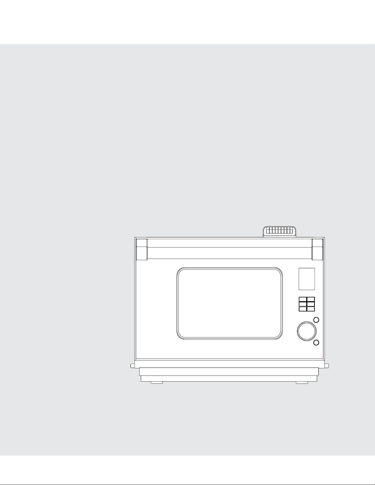
Installation Guide
Combi Steam/Convect
™
Oven and
Built-In Trim Kit
VCSO210/CVCSO201
VTKS300
1E 1
IMPORTANT–Please Read and Follow!
• Before beginning, please read these instructions completely and carefully.
• Be sure to DISCONNECT THE PLUG of the microwave oven from the electrical outlet before installing the built-in trim kit.
Remove the turntable from the oven cavity.
• Because the kit includes metal parts, caution should be used in handling and installation to avoid the possibility of injury.
• Do not remove permanently affixed labels, warnings, or plates from the product. This may void the warranty.
• Please observe all local and national codes and ordinances.
•Theinstallershouldleavetheseinstructionswiththeconsumerwhoshouldretainforlocalinspector’suseandfor
futurereference.
• This built-in trim kit is designed for use ONLY WITH COMBI STEAM/CONVECT™ OVEN.
• Your oven can be built into a cabinet or wall or above any electric wall oven, gas wall oven or warming drawer.
• NOTE: The bottom of the cut-out opening for built-in use must be 36 inches (915 mm) or higher from the floor.
• The electrical requirements for this oven are 120 volts, 15 amps. The oven has a 5-15 plug and requires a 5-15 receptacle.
• PLEASE READ THESE INSTRUCTIONS THOROUGHLY BEFORE BEGINNING INSTALLATION!
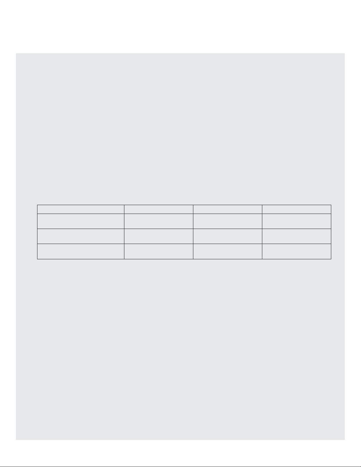
HEIGHT WIDTH DEPTH
Cabinet or wall opening
19" - 19 1/8"
(482 mm - 486 mm)
28"
(712 mm)
23 1/4" minimum
(509.5 mm minimum)
Built-in kit frame assembly
22 1/8"
(562.1 mm)
29 1/2"
(749.3 mm)
Combi Steam/Convect™ Oven
17 1/4"
(438 mm)
21 3/4"
(553 mm)
18 3/8"
(468 mm)
2 E
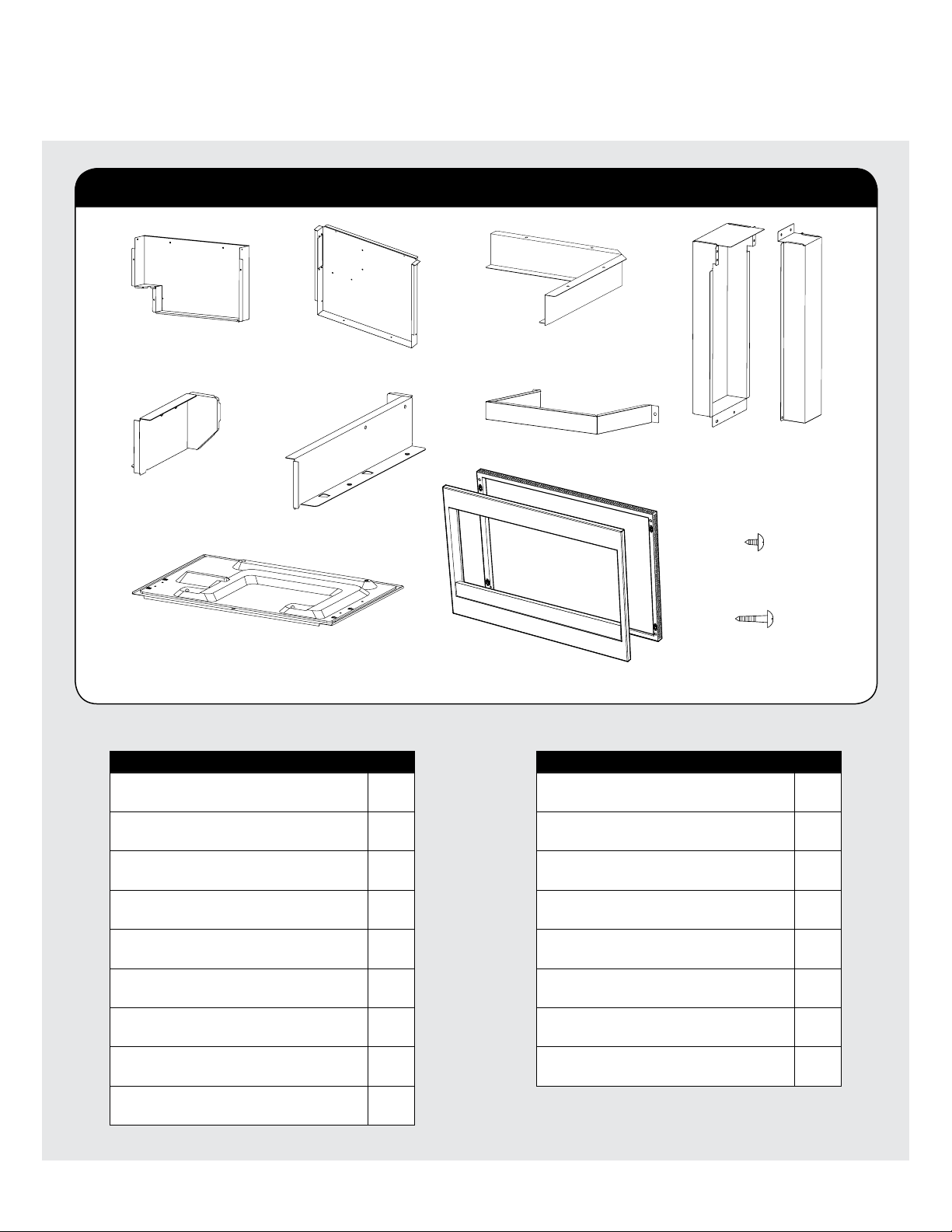
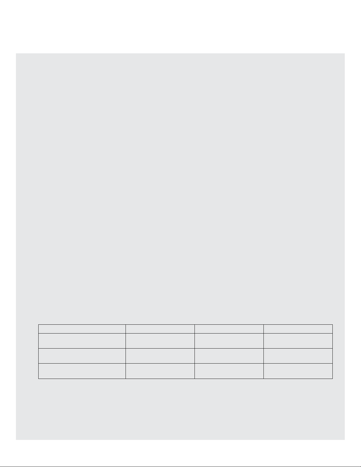
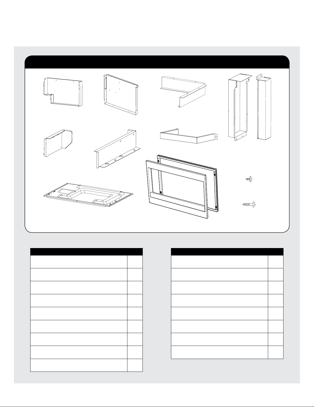
Provided Parts
PartNameQty
Exhaust Duct Back
PDUC-B107WRWZ
1
Exhaust Duct Upper
PDUC-B105WRWZ
1
Divide Plate L
PSKR-A486WRWZ
1
Divide Plate R
PSKR-A487WRWZ
1
Rectifier Plate L
PSKR-A484WRWZ
1
Exhaust Duct Left
PDUC-B108WRWZ
1
Exhaust Duct Right
PDUC-B117WRWZ
1
Exhaust Duct Bottom
PDUC-B106WRWZ
1
Frame Assembly
DDECAB012MRK0
1
Parts Included in VTKS300 kits
EXHAUST DUCT BACK
QTY 1
DIVIDE PLATE L
QTY 1
DIVIDE PLATE R
QTY 1
REAR SPACER
QTY 1
EXHAUST
DUCT LEFT
QTY 1
EXHAUST DUCT BOTTOM
QTY 1
FRAME ASSEMBLY
QTY 1
SCREW (A) - SHORT
QTY 23
SCREW (B) - LONG
QTY 8
EXHAUST
DUCT RIGHT
QTY 1
EXHAUST DUCT UPPER
QTY 1
RECTIFIER PLATE L
QTY 1
PartNameQty
Screw (A)
XHTS740P08000
23
Screw (B)
XMMS841P13000
8
Rear Spacer
PSPAFA003WRWZ
1
Cushion 1 5/8" x 16", 15 mm x 405 mm
PCUS-A245WRPZ
2
Cushion 2 1/4" x 24-3/8", 5 mm x 618 mm
PCUS-A247WRPZ
1
Cushion 3 1-1/8" x 27-1/8", 30 mm x 689 mm
PCUS-A249WRPZ
1
Cushion 4 1/4" x 12", 5 mm x 305 mm
PCUS-A251WRPZ
1
Cushion 5 1/4" x 15", 5 mm x 382 mm
PCUS-A253WRPZ
1
3E
Preparation
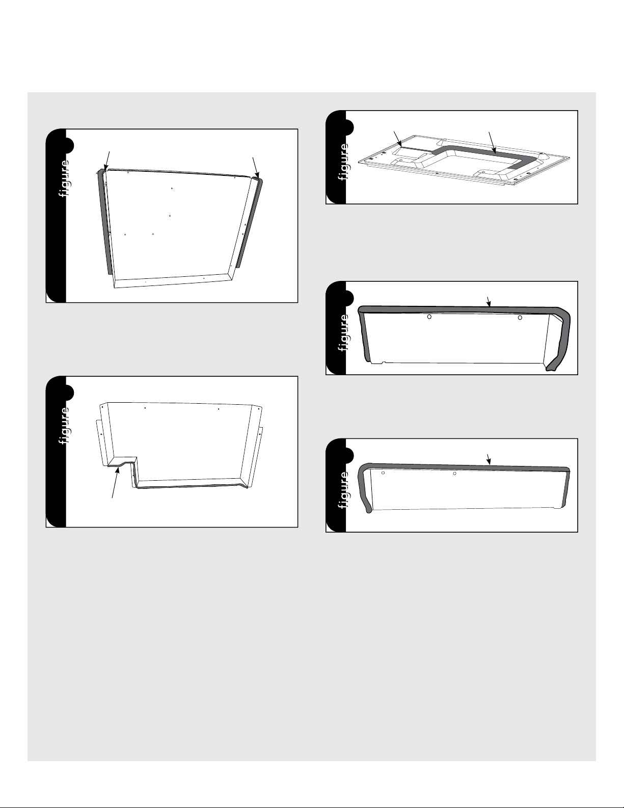
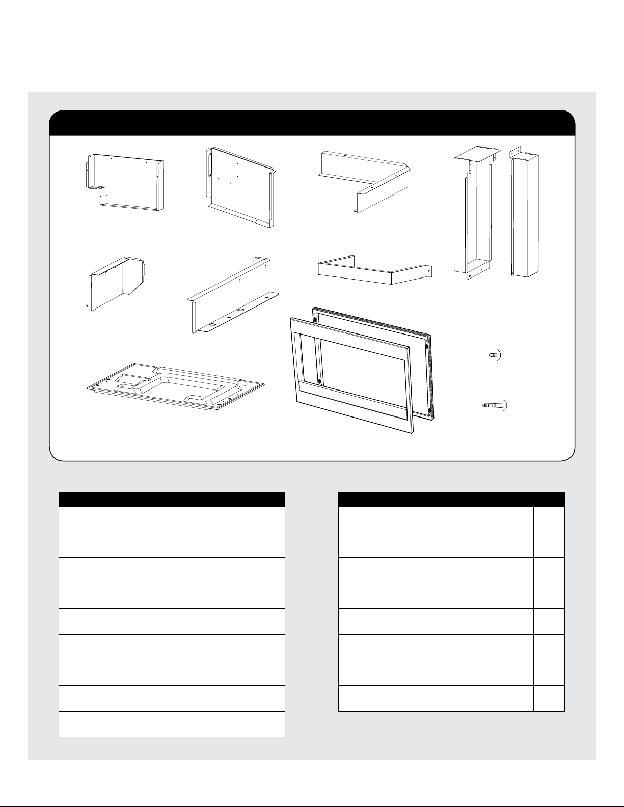
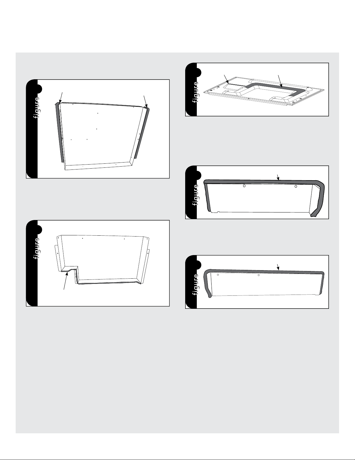
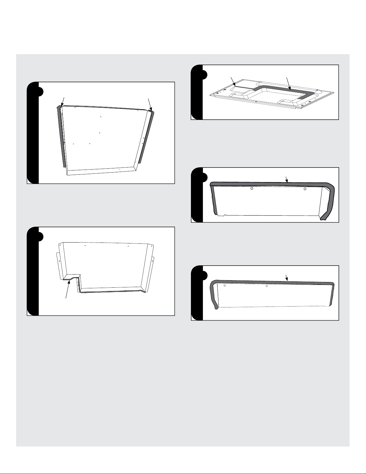
Follow the directions from 1 to 5 to attach cushions to some parts.
1
CUSHION 1
CUSHION 1
1. EXHAUST DUCT UPPER
Remove the backing paper from each CUSHION 1. Attach the
CUSHIONS 1 to each side flange of the EXHAUST DUCT UPPER as
shown in the Figure 1.
2
CUSHION 2
2. EXHAUST DUCT BACK
Remove the backing paper from CUSHION 2. Attach the CUSHION
2 at the lower flange of the EXHAUST DUCT BACK as shown in the
Figure 2.
3
CUSHION 3
A
3. EXHAUST DUCT BOTTOM
Remove the backing paper from CUSHION 3. Attach the CUSHION
3 to the EXHAUST DUCT BOTTOM as shown in the Figure 3.
* Start A to attach the CUSHION.
4
CUSHION 4
4. DIVIDE PLATE L
Remove the backing paper from CUSHION 4. Attach the CUSHION
4 to the DIVIDE PLATE L as shown in the Figure 4.
5
CUSHION 5
5. DIVIDE PLATE R
Remove the backing paper from CUSHION 5. Attach the CUSHION
5 to the DIVIDE PLATE R as shown in the Figure 5.
4 E
Installation
19" - 19
1
/
8
"
(482 mm - 486 mm)
23
1
/
4
(590.5 mm)
"
(712 mm)
28”
CL
7
7
/
8
"
(200 mm)
1
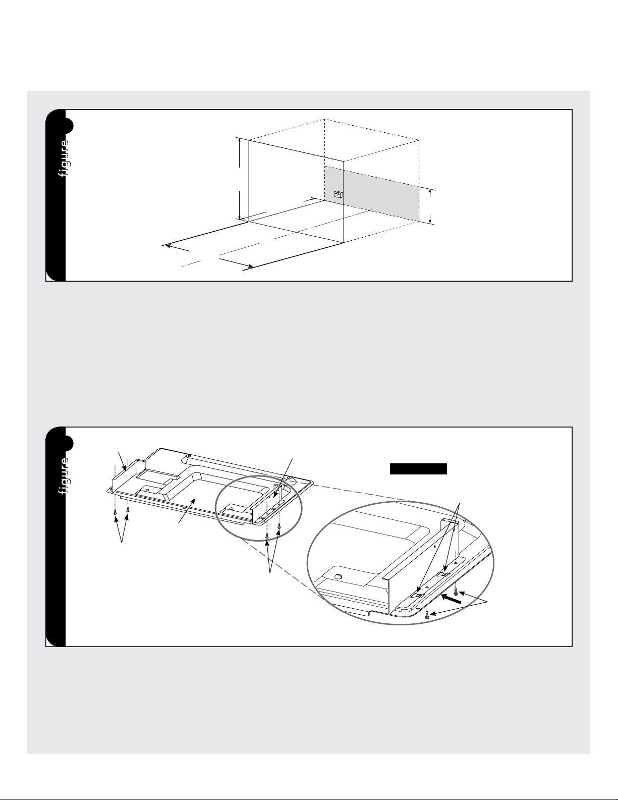
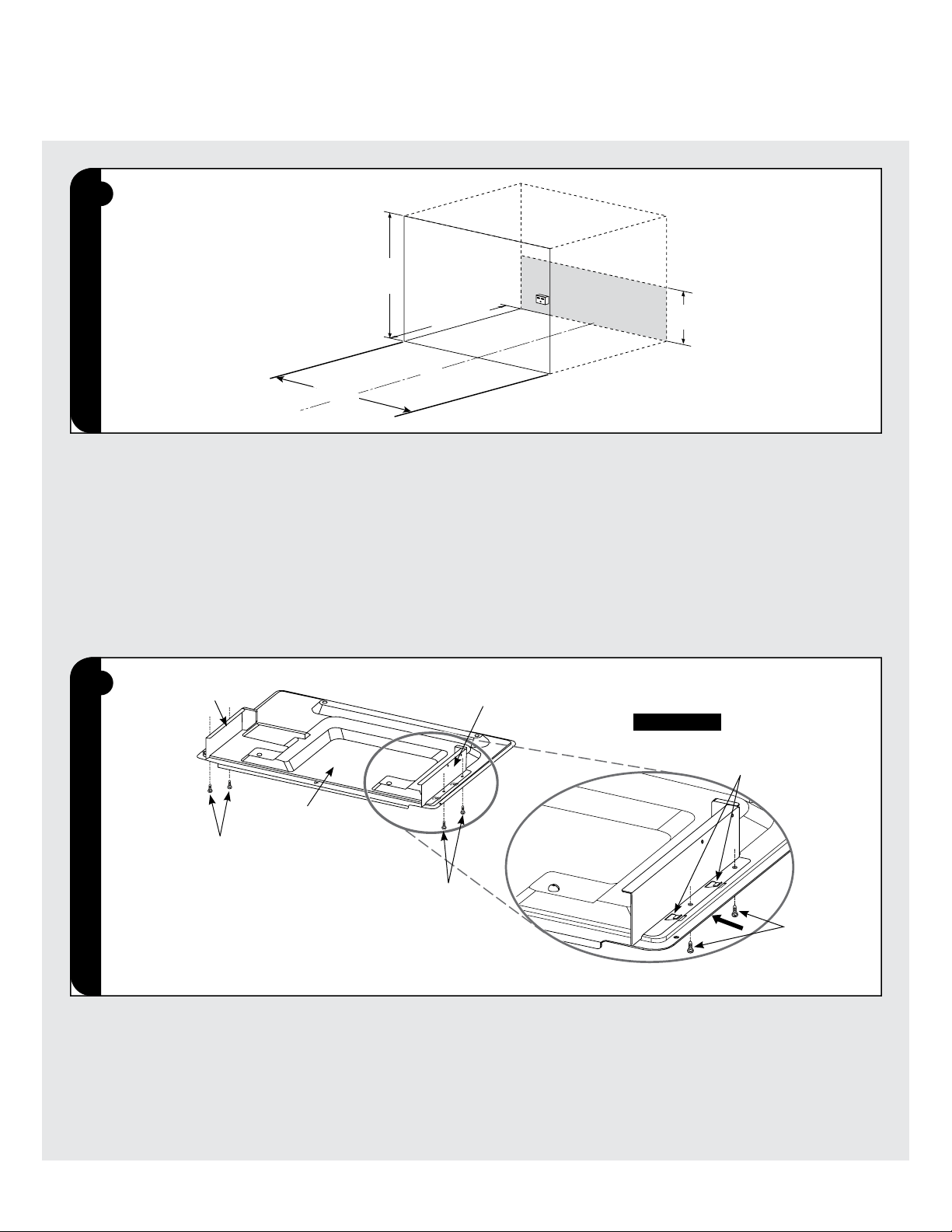
STEP 1: CABINET OR WALL OPENING
Provide an opening in the wall or cabinet shown in Figure 1.
The depth should be minimum 23 1/4" (590.5 mm). The floor of the
opening should be constructed of plywood strong enough to support
the weight of the oven (about 51 lbs.,23 kg) and should be level for
proper operation of the oven.
NOTE: While the proper functioning of the oven does not require
that the opening be enclosed (with sides, ceiling and rear partition),
this may be required by local code, and it is suggested that the local
code be checked for any such requirement.
ELECTRICAL SUPPLY
At the rear of the opening, provide a 3 pronged, polarized, electrical
outlet, 120 volt A.C., 15 amp. or larger.
This outlet should be located in the shaded area of Figure 1.
It is exceedingly important that the outlet be 120 volts and 15 amps.
for optimum oven performance.
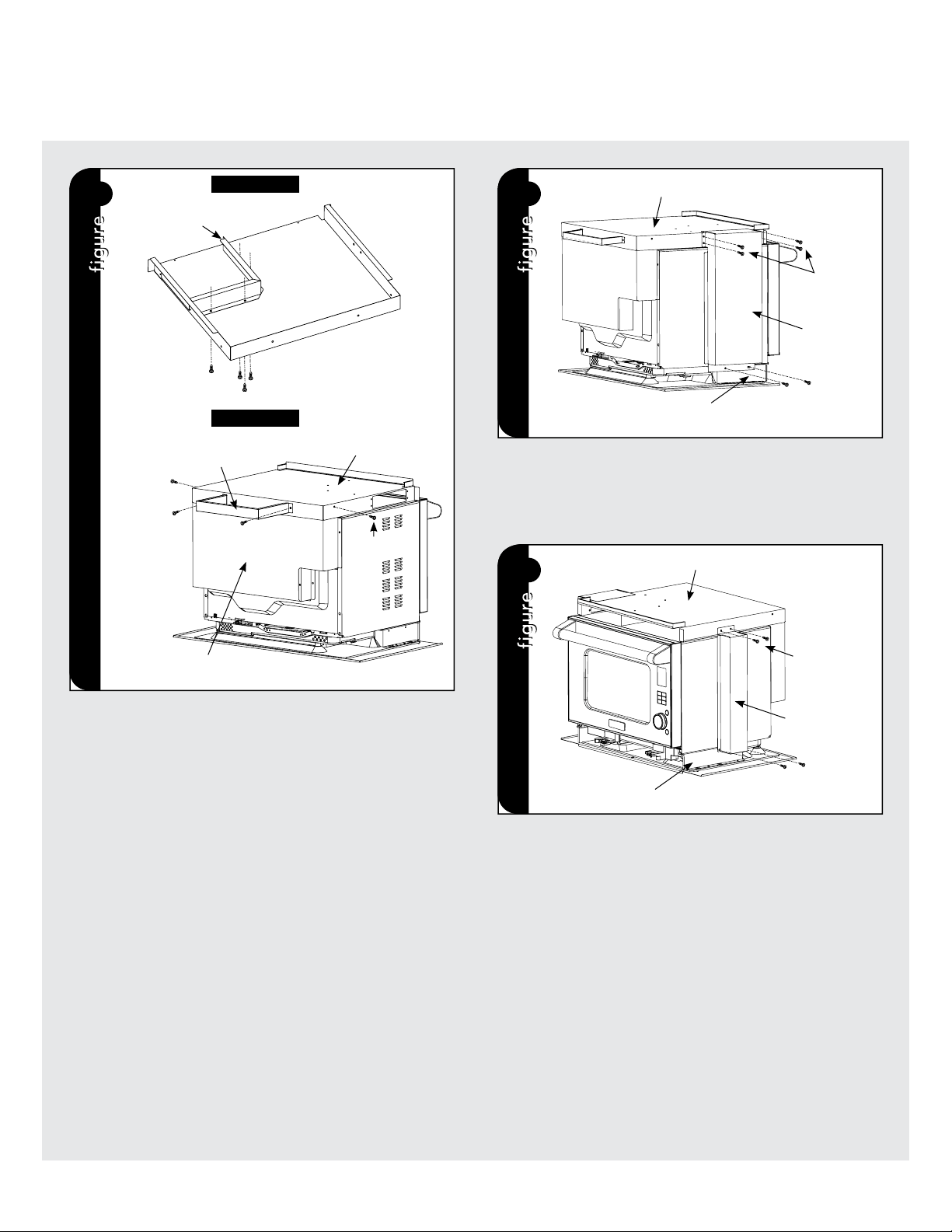
STEP 2: INSTALLATION OF EXHAUST DUCT BOTTOM & DIVIDE
PLATE L/R
It is recommended that a sheet of cardboard or other protective
material should be placed on the table or countertop to prevent
damage to the surface during assembly.
2.1 Place DIVIDE PLATE L/R over 2 catches on EXHAUST DUCT
BOTTOM.
2.2 Lock them into EXHAUST DUCT BOTTOM by sliding DIVIDE
PLATE L/R in the direction of the arrow as shown in Figure 2-A.
2.3 Tighten 4 SCREWS (A) from the bottom at the left and right sides
as shown in Figures 2 and 2-A.
2
DIVIDE PLATE L
SCREW (A)
EXHAUST DUCT
BOTTOM
SCREW (A)
SCREW (A)
CATCHES
DIVIDE PLATE R
FIGURE 2-A
5E
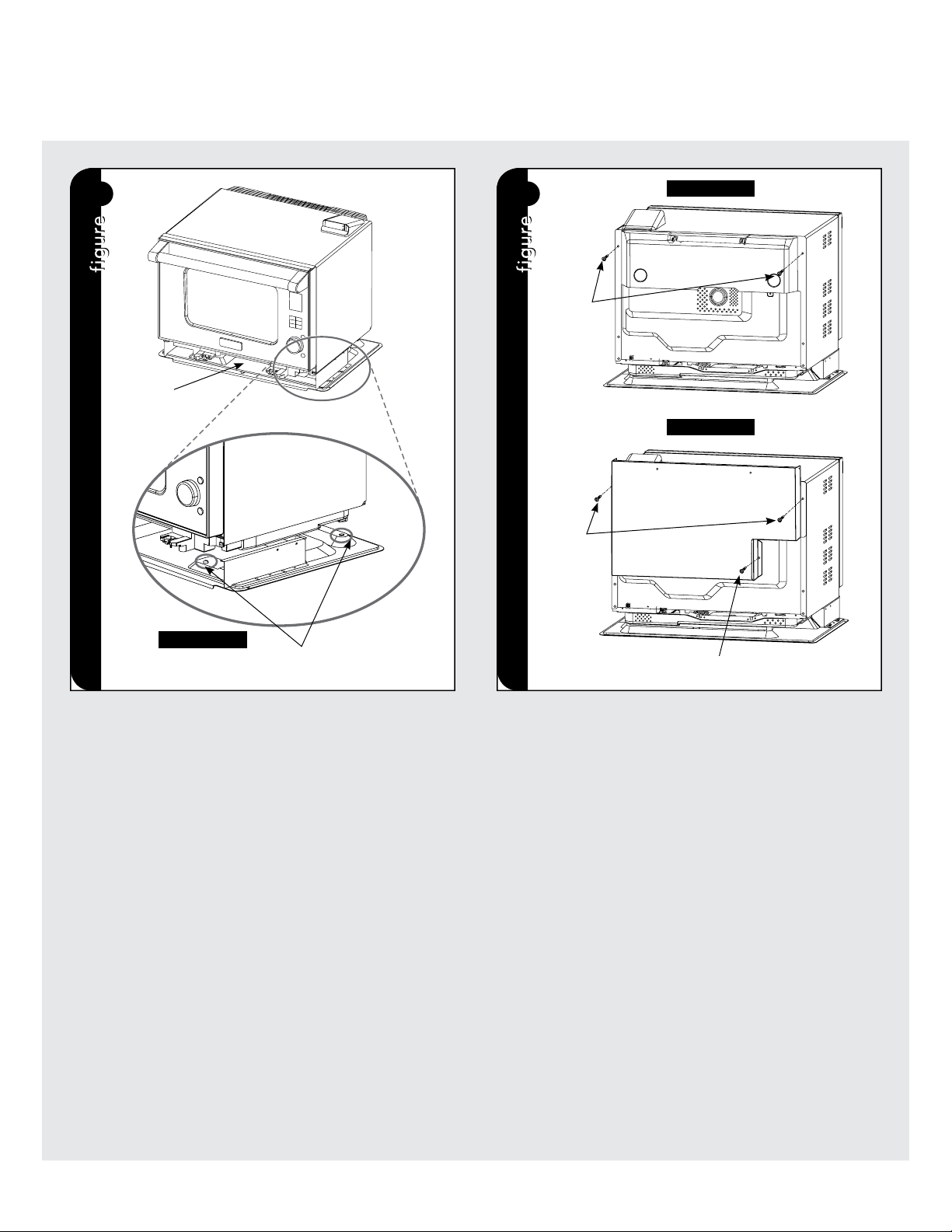
STEP 3: EXHAUST DUCT BOTTOM INSTALLATION
Place the oven onto the EXHAUST DUCT BOTTOM, lowering the 4
feet of the oven onto the projections at the 4 corners of EXHAUST
DUCT BOTTOM as shown in Figure 3-A.
3
STEP 4: EXHAUST DUCT BACK INSTALLATION
4.1 Remove 2 screws (#1) from upper both sides of the oven as shown
in Figure 4-A to install the EXHAUST DUCT BACK. (Save 2 screws
to be used at step 4.2.)
4.2 Secure EXHAUST DUCT BACK to the oven with the screws (#1)
removed at step 4.1 and a SCREW (A) as shown in Figure 4-B.
4
#1
#1
FIGURE 4-A
FIGURE 4-B
SCREW (A)
EXHAUST DUCT BACK
EXHAUST DUCT
BOTTOM
Installation
FIGURE 3-A
SCREW (A)
6 E
Installation
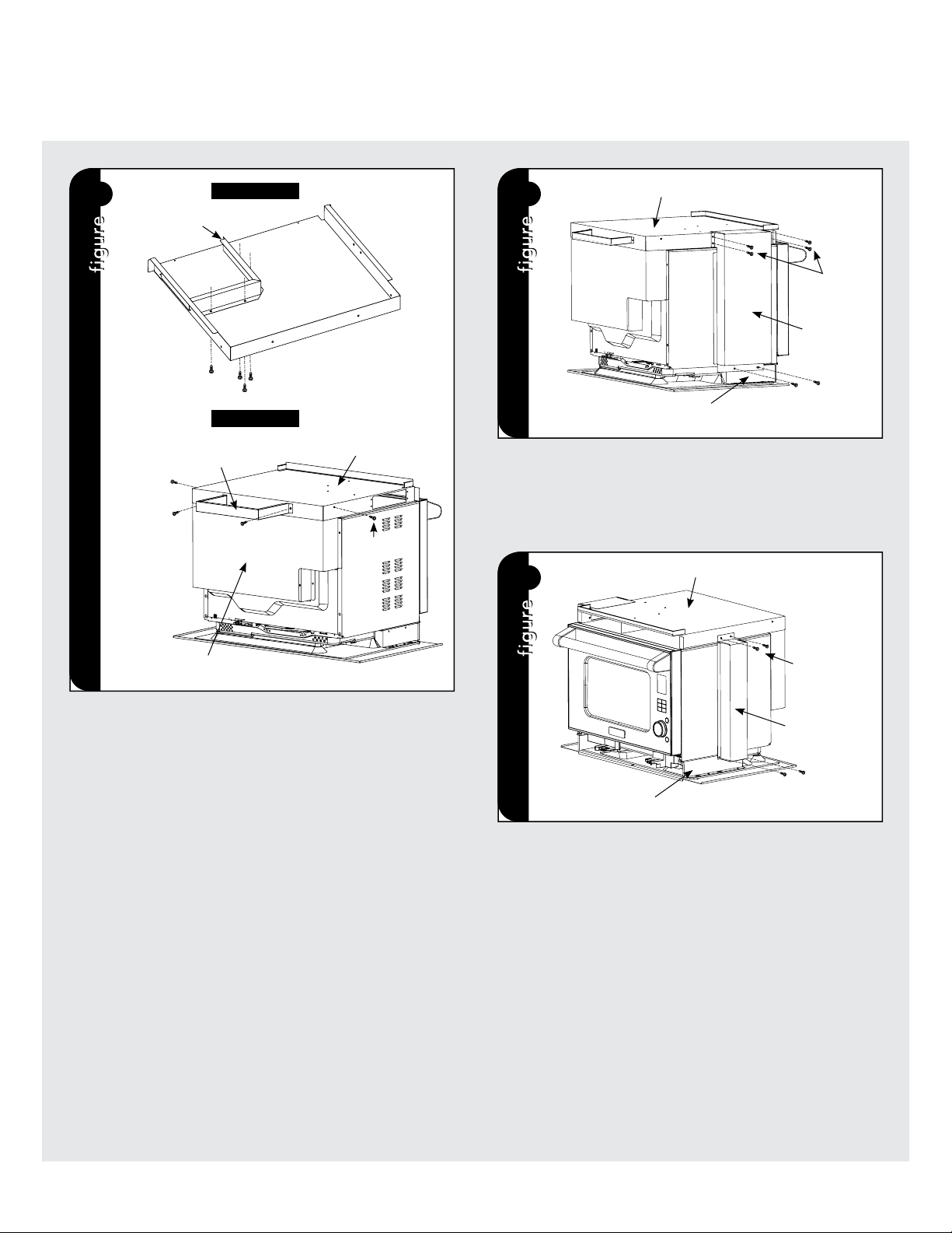
STEP 5: INSTALLATION OF REAR SPACER AND EXHAUST DUCT
UPPER
5.1 Attach RECTIFIER PLATE L to inside of EXHAUST DUCT UPPER
with 4 SCREWS (A) as shown in Figure 5-A.
5.2 Place EXHAUST DUCT UPPER over the oven and EXHAUST DUCT
BACK, and attach REAR SPACER with 2 SCREWS (A) in Figure
5-B.
5.3 Tighten together EXHAUST DUCT UPPER and EXHAUST DUCT
BACK at the left and right sides with 2 SCREWS (A) as shown in
Figure 5-B.
6
4 SCREWS (A)
EXHAUST DUCT UPPER
EXHAUST
DUCT LEFT
2 SCREWS (A)
DIVIDE PLATE L
STEP 6: INSTALLATION OF EXHAUST DUCT LEFT
6.1 Attach EXHAUST DUCT LEFT to the left wall of the oven.
6.2 Tighten with 6 screws (A) as shown in Figure 6.
7
EXHAUST DUCT UPPER
EXHAUST
DUCT RIGHT
2 SCREWS (A)
2 SCREWS (A)
DIVIDE PLATE R
STEP 7: INSTALLATION OF EXHAUST DUCT RIGHT
7.1 Attach EXHAUST DUCT RIGHT to the right wall of the oven.
7.2 Tighten with 4 screws (A) as shown in Figure 7.
5
REAR SPACER
FIGURE 5-A
FIGURE 5-B
EXHAUST DUCT
UPPER
EXHAUST DUCT UPPER
EXHAUST DUCT BACK
4 SCREWS (A)
SCREW (A)
SCREW (A)
SCREW (A)
SCREW (A)
RECTIFIER PLATE L
7E
Installation
CL
8
FIGURE 8-A
FIGURE 8-B
FLANGE
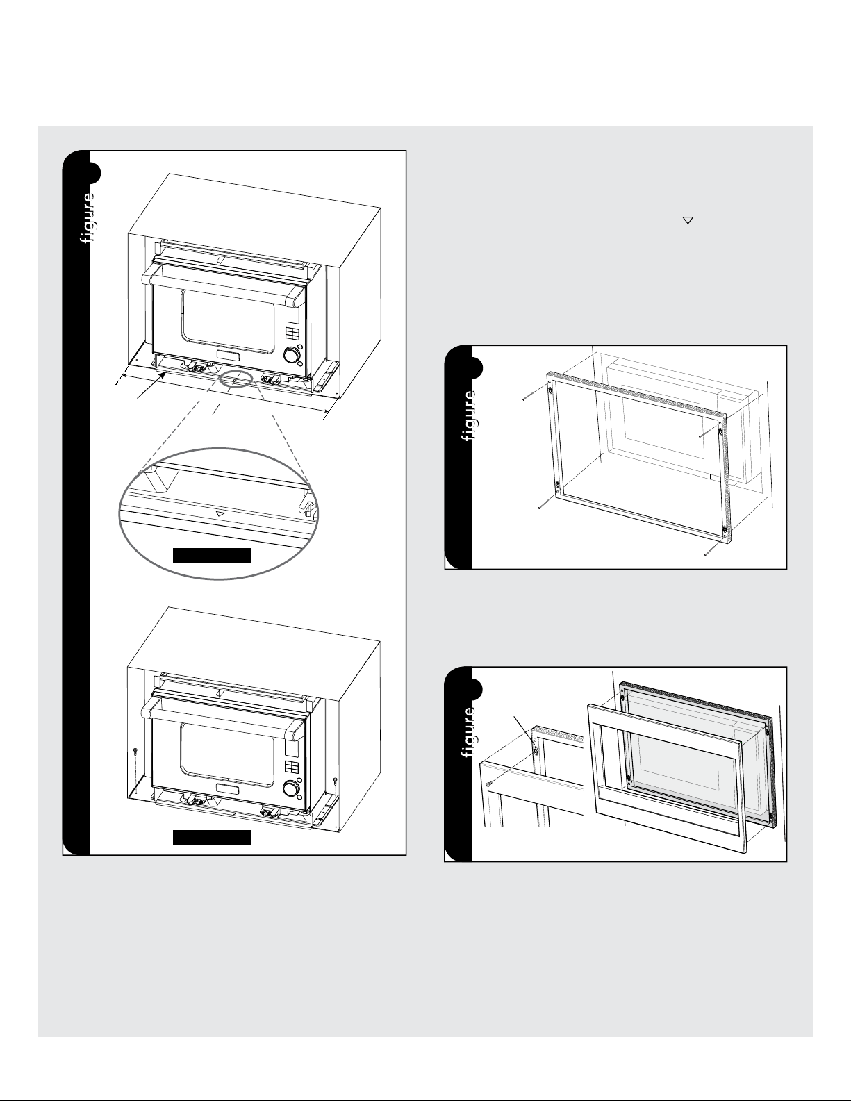
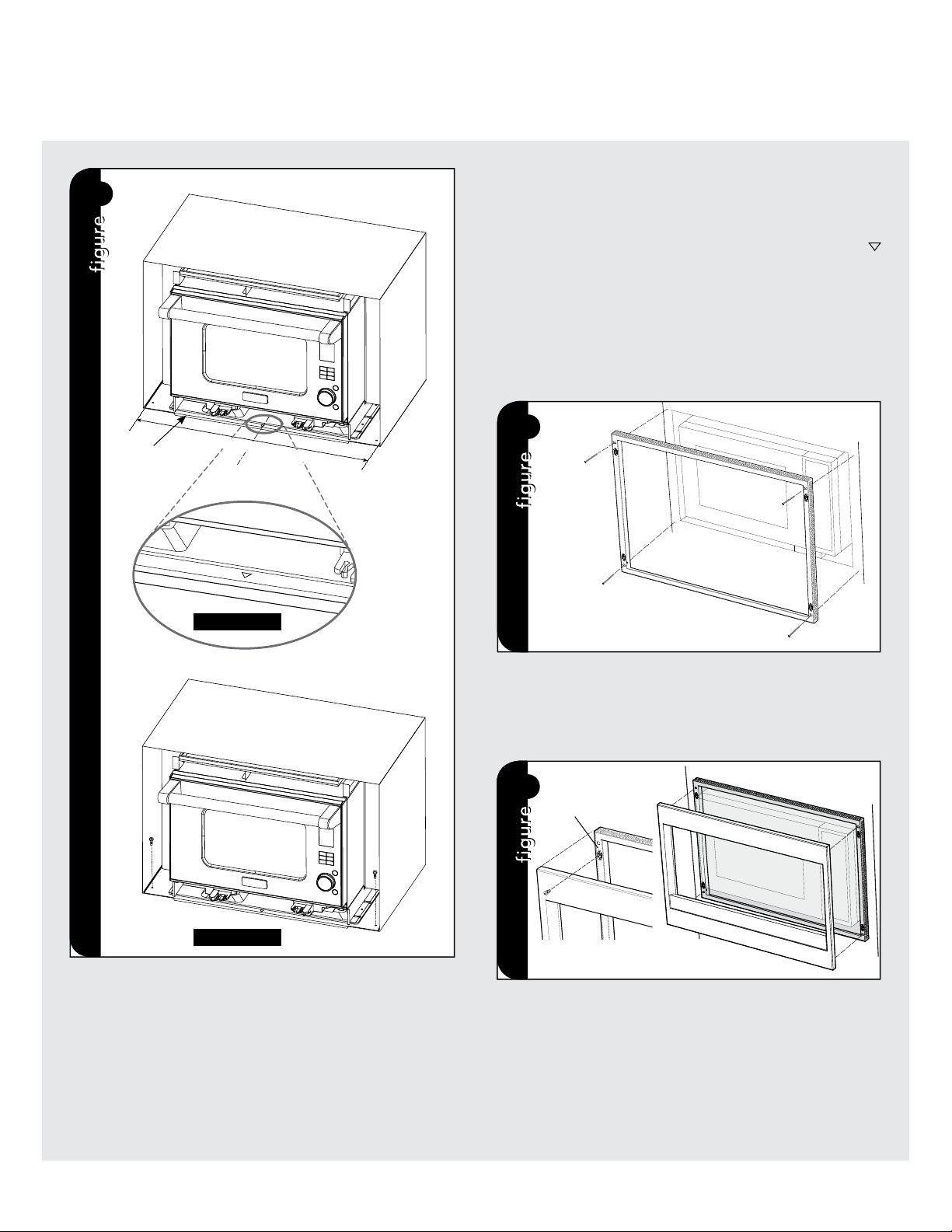
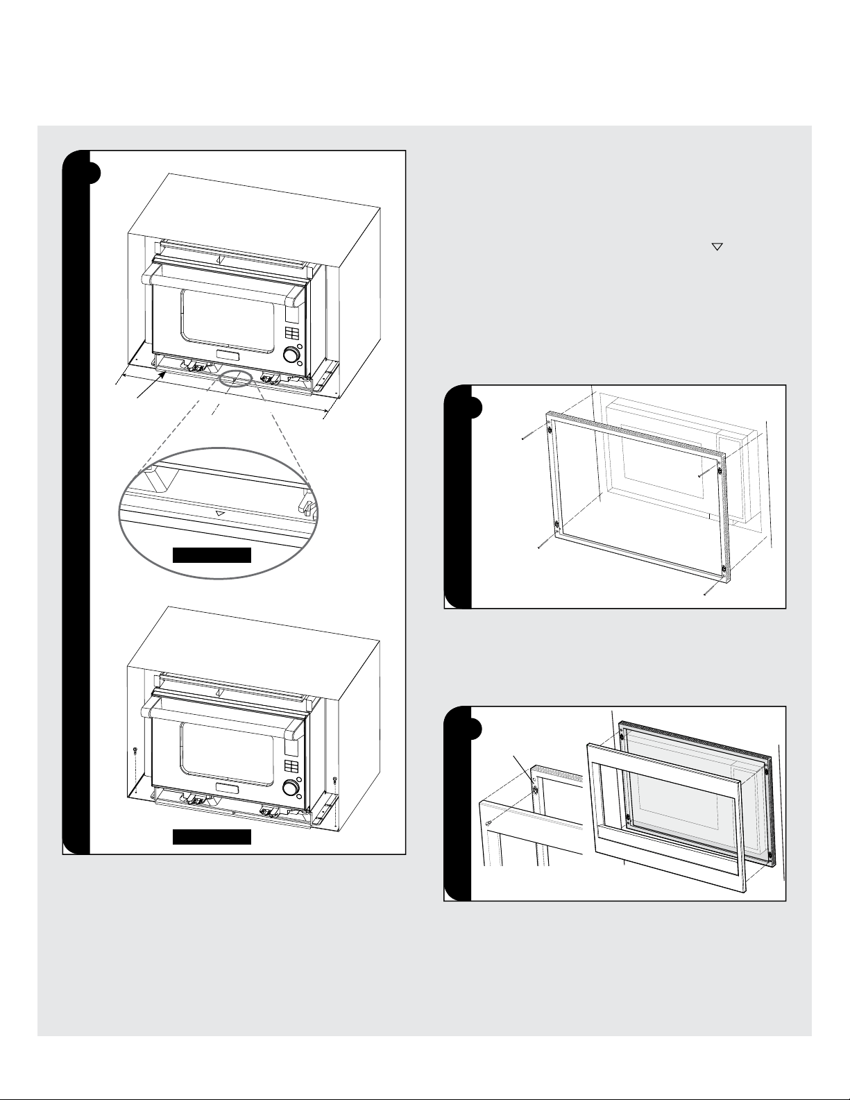
STEP 8: OVEN INSTALLATION
MOUNTING TEMPLATE: Align the mounting template center line with
the center of the cutout and the floor line with the floor of the cutout.
Tape it into place. Predrill 4 holes marked "A" with a 1/16" drill bit.
Remove template from the cabinet.
CAUTION: Never hold the handle when moving the oven. Two persons
are required to install the oven.
8.1 Establish center line of opening and mark front edge.
8.2 Place the oven on a table or stand positioned in front of the
cabinet where the oven is to be installed. One person should
hold the oven while the other connects it to the electrical outlet.
8.3 Install the oven into the shelf with adjusting
mark on EXHAUST
DUCT BOTTOM to the center line marked on front edge as
shown in Figures 8 and 8-A. Then push the oven until the flange
of EXHAUST DUCT BOTTOM touches the edge of the wall or
cabinet opening. Avoid pinching the cord between the oven and
any wall as shown in Figure 8.
8.4 Secure EXHAUST DUCT BOTTOM to the shelf with 2 screws (B)
as shown in Figure 8-B.
9
SCREW (B)
SCREW (B)
SCREW (B)
SCREW (B)
STEP 9: FRAME INSTALLATION
Position the BACK FRAME to align with the predrilled holes that were
drilled with the mounting template. Check that it is level and then
secure with four SCREWS (B). See Figure 9.
!
SNAP
ATTACHMENT
STEP 10: DECORATION INSTALLATION
Place the FRONT decoration onto the FRAME and align ball studs
and receivers. Secure the DECORATION to the FRAME by firmly
pushing the front frame onto the back frame engaging the four (4)
snap attachments. See Figure 10.
SCREW (B)
SCREW (B)
1 F1
Four Combi Steam/Convect
™
et kit de garniture à encastrer
VC
SO210/CVCSO201
VTKS300
IMPORTANT – Prière de lire et de suivre!
• Prière de lire attentivement toutes ces directives avant de commencer.
• Veiller à DÉBRANCHER LA FICHE du four à micro-ondes de la prise électrique avant d'installer la garniture à encastrer. Retirer
la table tournante de la cavité du four.
• Le kit comprend des parties métalliques, il faut faire attention lors de la manipulation et de l'installation pour éviter d'éventuelles
blessures.
•Ne pas retirer de façon permanente les étiquettes, les mises en garde ou les plaques fixées au produit. Cela pourrait annuler
la garantie.
• Veuillez observer tous les codes et règlements locaux et nationaux.
•L'installateurdevralaissercesdirectivesauclientquidevralesconserverpourl'usaged'uninspecteurlocaletpour
référenceultérieure.
• Ce kit de garniture à encastrer est conçu pour être utilisé uniquement avec le FOUR COMBI STEAM/CONVECT™.
• Votre four peut être installé dans une armoire, sur un mur, au-dessus d'un four mural électrique ou à gaz, ou d'un tiroir
chauffe-plat.
•NOTE : Le bas de la découpe pour encastrer doit est à au moins 36 pouces (915 mm) du plancher.
• L'alimentation électrique pour ce four est de 120 volts, 15 ampères. Ce four dispose d'une fiche 5-15 et exige une prise 5-15.
•VEUILLEZ LIRE ATTENTIVEMENT CES INSTRUCTIONS AVANT DE COMMENCER L'INSTALLATION!
HAUTEUR LARGEUR PROFONDEUR
Découpe de l'armoire ou du mur
19 po - 19 1/8 po
(482 mm - 486 mm)
28 po
(712 mm)
23 1/4 po minimum
(509,5 mm minimum)
Ensemble de cadres intégré
22 1/8 po
(562,1 mm)
29 1/2 po
(749,3 mm)
Four Combi Steam/Convect™
17 1/4 po
(438 mm)
21 3/4 po
(553 mm)
18 3/8 po
(468 mm)
Guide d’installation
2F 2
Pièces fournies
NomsdespiècesQté
Conduit d'évacuation arrière
PDUC-B107WRWZ
1
Conduit d'évacuation supérieur
PDUC-B105WRWZ
1
Plaque de séparation G
PSKR-A486WRWZ
1
Plaque de séparation D
PSKR-A487WRWZ
1
Plaque de redresseur G
PSKR-A484WRWZ
1
Conduit d'évacuation gauche
PDUC-B108WRWZ
1
Conduit d'évacuation droit
PDUC-B117WRWZ
1
Conduit d'évacuation inférieur
PDUC-B106WRWZ
1
Ensemble de cadres
DDECAB012MRK0
1
Pièces comprises dans les kits VTKS300
CONDUIT D'ÉVACUATION
ARRIÈRE - QTÉ 1
PLAQUE DE
SÉPARATION G
QTÉ 1
PLAQUE DE
SÉPARATION D
QTÉ 1
ENTRETOISE ARRIÈRE
QTÉ 1
CONDUIT
D'ÉVACUATION
GAUCHE
QTÉ 1
CONDUIT D'ÉVACUATION
INFÉRIEUR
- QTÉ 1
ENSEMBLE DE CADRES
QTÉ 1
VIS (A) - COURTE
QTÉ 23
VIS (B) - LONGUE
QTÉ 8
CONDUIT
D'ÉVACUATION
DROIT
QTÉ 1
CONDUIT D'ÉVACUATION
SUPÉRIEUR - QTÉ 1
PLAQUE DE
REDRESSEUR G
- QTÉ 1
NomsdespiècesQté
Vis (A)
XHTS740P08000
23
Vis (B)
XMMS841P13000
8
Entretoise arrière
PSPAFA003WRWZ
1
Coussinet 1 5/8 po x 16 po , 15 mm x 405 mm
PCUS-A245WRPZ
2
Coussinet 2 1/4 po x 24-3/8 po, 5 mm x 618 mm
PCUS-A247WRPZ
1
Coussinet 3 1-1/8 po x 27-1/8 po, 30 mm x 689 mm
PCUS-A249WRPZ
1
Coussinet 4 1/4 po x 12 po, 5 mm x 305 mm
PCUS-A251WRPZ
1
Coussinet 5 1/4 po x 15 po, 5 mm x 382 mm
PCUS-A253WRPZ
1
3 F3
Préparation
Suivre les instructions de 1 à 5 pour attacher les coussinets à certaines
pièces.
1
COUSSINET 1
COUSSINET 1
1. CONDUIT D'ÉVACUATION SUPÉRIEUR
Retirer le papier protecteur de chaque COUSSINET
1. Fixer
les COUSSINETS 1 à chaque rebord latéral du CONDUIT
D'ÉCHAPPEMENT SUPÉRIEUR comme indiqué à la Figure 1.
2
COUSSINET 2
2. CONDUIT D'ÉVACUATION ARRIÈRE
Retirer le papier protecteur du COUSSINET
2. Fixer le COUSSINET 2
au rebord inférieur du CONDUIT D'ÉCHAPPEMENT ARRIÈRE comme
indiqué à la Figure 2.
3
COUSSINET 3
A
3. CONDUIT D'ÉVACUATION INFÉRIEUR
Retirer le papier protecteur du COUSSINET
3. Fixer le COUSSINET
3 au CONDUIT D'ÉCHAPPEMENT SUPÉRIEUR comme indiqué à la
Figure 3.
* Commencer à fixer le COUSSINET en A.
4
COUSSINET 4
4. PLAQUE DE SÉPARATION G
Retirer le papier protecteur du COUSSINET
4. Fixer le COUSSINET
4à la PLAQUE DE SÉPARATION G comme indiqué à la Figure 4.
5
COUSSINET 5
5. PLAQUE DE DIVISION D
Retirer le papier protecteur du COUSSINET
5. Fixer le COUSSINET
5 à la PLAQUE DE SÉPARATION D comme indiqué à la Figure 5.

4F 4
Installation
19 po - 19
1
/
8
po
(482 mm - 486 mm)
23
1
/
4
(590,5 mm)
po
(712 mm)
28 po
CL
7
7
/
8
po
(200 mm)
1
ÉTAPE 1 : DÉCOUPE DE L'ARMOIRE OU DU MUR
Faire une ouverture dans le mur ou l'armoire comme indiqué à la
Figure 1.
La profondeur doit être au minimum de 23 1/4 po (590,5 mm). Le
plancher de l'ouverture doit être en contreplaqué assez fort pour
supporter le poids du four et sa propre charge (environ 23 kg [51 lb])
et doit être à un niveau convenable pour l'utilisation du four.
REMARQUE : Bien que le bon fonctionnement du four ne demande
pas que l'ouverture soit close (avec cloisons latérales, arrière et
plafond), le code local pourrait l'exiger; il est donc suggéré de vérifier
ce point.
ALIMENTATION ÉLECTRIQUE
À l'arrière de l'ouverture, installer une prise électrique polarisée pour
fiche à trois broches, 120 volts CA, 15 A ou plus.
La prise doit se trouver dans l'aire ombrée comme indiqué à la Figure 1.
Il est excessivement important que la prise soit de 120 volts et 15
ampères pour une performance optimale du four.
ÉTAPE 2 : INSTALLATION DU CONDUIT D'ÉVACUATION
INFÉRIEUR ET DES PLAQUES DE SÉPARATION G ET D
Il est recommandé qu'une feuille en carton ou autre matériau
de protection soit posée sur la table ou le comptoir pour éviter
d'endommager la surface lors du montage.
2.1 Placer les PLAQUES DE SÉPARATION G ET D sur les 2 tenons
du CONDUIT D'ÉVACUATION INFÉRIEUR .
2.2 Bloquer les PLAQUES dans le CONDUIT D'ÉVACUATION
INFÉRIEUR en les glissant dans la direction de la flèche, comme
indiqué à la Figure 2-A.
2.3 Serrer les 4 VIS (A) à partir du bas sur les côtés gauche et droit
comme indiqué dans les Figures 2 et 2-A.
2
PLAQUE DE SÉPARATION G
VIS (A)
CONDUIT
D'ÉVACUATION
INFÉRIEUR
VIS (A)
VIS (A)
TENONS
PLAQUE DE SÉPARATION D
FIGURE 2-A

5 F5
ÉTAPE 3 : INSTALLATION DU CONDUIT D'ÉVACUATION INFÉRIEUR
Placer le four en abaissant ses 4 pattes sur les projections aux 4 coins
du bas CONDUIT D'ÉVACUATION INFÉRIEUR comme indiqué à la
Figure 3-A.
3
ÉTAPE 4 : INSTALLATION DU CONDUIT D'ÉVACUATION ARRIÈRE
4.1 Retirer les 2 vis (no 1) des deux côtés supérieurs du four,
comme indiqué dans la Figure 4-A pour installer le CONDUIT
D'ÉVACUATION ARRIÈRE. (Conserver les 2 vis pour les utiliser à
l'étape 4.2.)
4.2 Fixer le CONDUIT D'ÉVACUATION ARRIÈRE au four avec les vis
(# 1) retirées à l'étape 4.1 et une vis (A) comme indiqué à la Figure
4-B.
4
N
o
1
N
o
1
FIGURE 4-A
FIGURE 4-B
VIS (A)
CONDUIT D'ÉVACUATION
ARRIÈRE
CONDUIT
D'ÉVACUATION
INFÉRIEUR
Installation
FIGURE 3-A
VIS (A)
6F 6
Installation
ÉTAPE 5 : INSTALLATION DE L'ENTRETOISE ARRIÈRE ET DU
CONDUIT D'ÉVACUATION SUPÉRIEUR
5.1 Fixer la PLAQUE DE Redresseur G à l'intérieur du CONDUIT DE
VENTILATION SUPÉRIEUR avec 4 vis (A) comme indiqué dans la
Figure 5-A.
5.2 Placer le CONDUIT D'ÉVACUATION SUPÉRIEUR sur le four et
le CONDUIT D'ÉVACUATION ARRIÈRE, et fixer l'ENTRETOISE
ARRIÈRE avec 2 vis (A) comme indiqué à la Figure 5-B.
5.3 Fixer ensemble les CONDUITS D'ÉVACUATION SUPÉRIEUR
et ARRIÈRE sur les côtés gauche et droit avec 2 vis (A) comme
indiqué à la Figure 5-B.
6
4 VIS (A)
CONDUIT D'ÉVACUATION SUPÉRIEUR
CONDUIT
D'ÉVACUATION
GAUCHE
2 VIS (A)
PLAQUE DE SÉPARATION G
ÉTAPE 6 : INSTALLATION DU CONDUIT D'ÉVACUATION GAUCHE
Fixer le CONDUIT D'ÉVACUATION GAUCHE à la paroi gauche du
four, avec 6 vis (A) comme indiqué à la Figure 6.
7
CONDUIT D'ÉVACUATION SUPÉRIEUR
CONDUIT
D'ÉVACUATION
DROIT
2 VIS (A)
2 VIS (A)
PLAQUE DE SÉPARATION D
ÉTAPE 7 : INSTALLATION DU CONDUIT D'ÉVACUATION DROIT
Fixer le CONDUIT D'ÉVACUATION DROIT à la paroi droite du four,
avec 4 vis (A) comme indiqué à la Figure 7.
5
ENTRETOISE ARRIÈRE
FIGURE 5-A
FIGURE 5-B
CONDUIT
D'ÉVACUATION
SUPÉRIEUR
CONDUIT
D'ÉVACUATION
SUPÉRIEUR
CONDUIT D'ÉVACUATION
ARRIÈRE
4 VIS (A)
VIS (A)
VIS (A)
VIS (A)
VIS (A)
PLAQUE DE
REDRESSEUR G
7 F7
Installation
CL
8
FIGURE 8-A
FIGURE 8-B
REBORD
ÉTAPE 8 : INSTALLATION DU FOUR
GABARIT DE MONTAGE : Aligner la ligne médiane du gabarit de
montage avec le centre de la découpe et la ligne de plancher avec
le plancher de la découpe. Coller en place avec du ruban adhésif.
Percer les 4 trous marqués « A » avec un foret de 1/16 po. Enlever le
gabarit de l'armoire
MISE EN GARDE : Ne jamais tenir la poignée de la porte en déplaçant
le four. Il faut deux personnes pour installer le four.
8.1 Établir la ligne médiane de l'ouverture et marquer le bord avant.
8.2 Poser le four sur une table ou un support placé en face de
l'armoire où il doit être installé. Une personne doit tenir le four
tandis que l'autre le branche à la prise électrique.
8.3 Installer le four sur la tablette avec la marque d'ajustement
du CONDUIT D'ÉVACUATION INFÉRIEUR à la ligne médiane
marquée sur le bord avant, comme indiqué aux Figures 8 et 8-A.
Pousser ensuite le four jusqu'à ce que le rebord du CONDUIT
D'ÉVACUATION INFÉRIEUR touche le bord de l'ouverture du
mur ou de l'armoire. Éviter de pincer le cordon entre le four et
le mur comme indiqué à la Figure 8.
8.4 Fixer le CONDUIT D'ÉVACUATION INFÉRIEUR avec 2 vis (B)
comme illustré à la Figure 8-B .
9
VIS (B)
VIS (B)
VIS (B)
VIS (B)
ÉTAPE 9 : INSTALLATION DU CADRE
Placer le CADRE ARRIÈRE pour qu'il soit aligné avec les trous percés
à l'aide du gabarit. Vérifier qu'il est de niveau puis le fixer avec deux
vis (B). Voir Figure 9.
!
FIXATION À
RESSORT
ÉTAPE 10 : INSTALLATION DE LA DÉCORATION
Poser la décoration AVANT sur le CADRE et aligner les pitons à
rotule et leurs récepteurs. Fixer la décoration au CADRE AVANT en
le poussant fermement contre le CADRE ARRIÈRE et en engageant
les quatre (4) fixations à ressort. Voir Figure 10.
VIS (B)
VIS (B)
1S 1
IMPORTANTE – ¡Lea y siga con atención!
• Antes de comenzar, lea estas instrucciones completa y detalladamente.
• Asegúrese de DESCONECTAR el horno microondas del tomacorriente eléctrico antes de instalar el juego de moldura para
empotrado. Retire el plato giratorio de la cavidad del horno.
• El juego incluye partes de metal por lo que debe manipularlo e instalarlo con precaución para evitar el riesgo de lesiones.
• No retire las etiquetas, advertencias o placas permanentes del producto. Esto puede anular la garantía.
• Cumpla todos los códigos y normas locales y nacionales.
•Elinstaladordebedevolverestasinstruccionesalclientequiendebeconservarlasparausodelinspectorlocalypara
referenciasfuturas.
• Este juego de moldaduras está diseñado para uso SÓLO CON EL HORNO COMBI STEAM/CONVECT™.
• Su horno puede ser empotrado dentro de un gabinete o pared o encima de cualquier horno de pared eléctrico, o cajón
calentador.
•NOTA: La parte inferior de la abertura de recorte para empotrado debe ser de 36 pulgadas (915 mm) o más alta desde el suelo.
•Los requisitos eléctricos de este horno son de 120 voltios, 15 amperios. El horno cuenta con un enchufe de 3 clavijas (5-15P)
y requiere un receptáculo de tres clavijas (5-15R).
• ¡LEA DETENIDAMENTE LAS INSTRUCCIONES ANTES DE COMENZAR LA INSTALACIÓN!
ALTURA ANCHO PROFUNDIDAD
Abertura del gabinete o pared
19" - 19 1/8"
(482 mm - 486 mm)
28"
(712 mm)
23 1/4" mínimo
(509.5 mm mínimo)
Juego de conjunto del marco
para empotrado
22 1/8"
(562.1 mm)
29 1/2"
(749.3 mm)
Horno Combi Steam/Convect™
17 1/4"
(438 mm)
21 3/4"
(553 mm)
18 3/8"
(468 mm)
Instrucciones de Instalación
Combi Steam/Convect™ Horno
yJuegodeMoldadurasparaEmpotrado
VCSO210
VTKS300
2 S2
Partes suministradas
NombredelaparteCant.
Ducto de escape posterior
PDUC-B107WRWZ
1
Ducto de escape superior
PDUC-B105WRWZ
1
Placa de división izquierda
PSKR-A486WRWZ
1
Placa de división derecha
PSKR-A487WRWZ
1
Placa de rectificador izquierda
PSKR-A484WRWZ
1
Ducto de escape izquierdo
PDUC-B108WRWZ
1
Ducto de escape derecho
PDUC-B117WRWZ
1
Ducto de escape inferior
PDUC-B106WRWZ
1
Conjunto del marco
DDECAB012MRK0
1
Partes incluidas en los juegos VTKS300
DUCTO DE ESCAPE
POSTERIOR
CANT. 1
PLACA DE DIVISIÓN
IZQUIERDA
CANT. 1
PLACA DE DIVISIÓN
DERECHA
CANT. 1
ESPACIADOR
POSTERIOR -
CANT. 1
ESCAPE DUCTO
IZQUIERDO
CANT.1
DUCTO DE ESCAPE INFERIOR
CANT. 1
CONJUNTO DEL MARCO
CANT. 1
TORNILLO (A) - CORTO
CANT. 23
TORNILLO (B) - LARGO
CANT. 8
ESCAPE DUCTO
DERECHO
CANT. 1
DUCTO DE ESCAPE
SUPERIOR -
CANT. 1
PLACA DE
RECTIFICADOR
IZQUIERDA -
CANT. 1
NombredelaparteCant.
Tornillo (A)
XHTS740P08000
23
Tornillo (B)
XMMS841P13000
8
Espaciador posterior
PSPAFA003WRWZ
1
Amortiguador 1 5/8" x 16", 15 mm x 405 mm
PCUS-A245WRPZ
2
Amortiguador 2 1/4" x 24-3/8", 5 mm x 618 mm
PCUS-A247WRPZ
1
Amortiguador 3 1-1/8" x 27-1/8", 30 mm x 689 mm
PCUS-A249WRPZ
1
Amortiguador 4 1/4" x 12", 5 mm x 305 mm
PCUS-A251WRPZ
1
Amortiguador 5 1/4" x 15", 5 mm x 382 mm
PCUS-A253WRPZ
1
3S 3
Preparación
Siga las instrucciones del 1 al 5 para fijar los amortiguadores a algunas
partes.
1
AMORTIGUADOR
1
AMORTIGUADOR
1
figura
figura
1. DUCTO DE ESPACE SUPERIOR
Retire el papel de protección de cada AMORTIGUADOR 1. Fije los
AMORTIGUADORES 1 a cada brida lateral del ducto de escape
superior como se muestra en la figura 1.
2
AMORTIGUADOR
2
figura
figura
2. DUCTO DE ESCAPE POSTERIOR
Retire el papel de protección del AMORTIGUADOR 2. Fije los
AMORTIGUADORES 2 a la brida inferior del DUCTO DE ESCAPE
POSTERIOR como se muestra en la figura 2.
2.
3
AMORTIGUADOR 3
A
figura
figura
3. DUCTO DE ESCAPE INFERIOR
Retire el papel de protección del AMORTIGUADOR 3. Fije los
AMORTIGUADORES 3 al DUCTO DE ESCAPE INFERIOR como se
muestra en la figura 3.
* Comience A para fijar el AMORTIGUADOR.
4
AMORTIGUADOR 4
figura
figura
4. PLACA DE DIVISIÓN IZQUIERDA
Retire el papel de protección del AMORTIGUADOR 4. Fije los
AMORTIGUADORES 4 a la placa de división izquierda como se
muestra en la figura 4.
5
AMORTIGUADOR 5
figura
figura
5. PLACA DE DIVISIÓN DERECHA
Retire el papel de protección del AMORTIGUADOR 5. Fije los
AMORTIGUADORES 5 a la PLACA DE DIVISIÓN DERECHA como
se muestra en la figura 5.
4 S4
Instalación
PASO 1: ABERTURA DEL GABINETE O PARED
Haga una abertura en la pared o en el gabinete mostrada en la figura 1.
La profundidad debe ser de un mínimo de 23 1/4" (590.5 mm). La
superficie de la abertura debe ser construida de madera laminada
lo suficientemente resistente para soportar el peso del horno
(aproximadamente 51 libras, 23 kilogramos) y debe ser nivelada para
obtener un funcionamiento adecuado del horno.
NOTA: Aunque el correcto funcionamiento del horno no requiere
que la abertura esté cerrada (con tabiques laterales, superiores y
posteriores), el código local puede exigirlo y se sugiere revisar en el
código local alguna indicación de ese tipo.
SUMINISTRO ELÉCTRICO
En la parte posterior de la abertura, debe haber un tomacorriente
eléctrico de tres clavijas polarizado de 120 voltios CA, 15 amperios
o mayor.
Este tomacorriente debe estar ubicado en el área sombreada de la
figura 1.
Es sumamente importante que el tomacorriente sea de 120 voltios y
15 amperios para el óptimo funcionamiento del horno.
PASO 2: INSTALACIÓN DEL DUCTO DE ESCAPE INFERIOR Y LA
PLACA DE DIVISIÓN I/D
Se recomienda colocar una lámina de cartón u otro material de
protección sobre la mesa o mostrador para evitar daños a la superficie
durante el montaje.
2.1 Coloque una PLACA DE DIVISIÓN I/D sobre 2 ganchos en el
DUCTO DE ESCAPE INFERIOR.
2.2 Bloquéelos en los DUCTOS DE ESCAPE INFERIOR al deslizar la
PLACA DE DIVISIÓN I/D en la dirección de la flecha como se
muestra en la figura 2-A.
2.3 Apriete 4 TORNILLOS (A) de la parte inferior en los lados derecho
e izquierdo, como se indica en las figuras 2 y 2-A.
2
19" - 19
1
/
8
"
(482 mm - 486 mm)
23
1
/
4
(590.5 mm)
"
(712 mm)
28”
CL
7
7
/
8
"
(200 mm)
LC
1
figura
figura
figura
figura
PLACA DE DIVISIÓN
IZQUIERDA
TORNILLO (A)
DUCTO DE ESCAPE
INFERIOR
TORNILLO (A)
TORNILLO (A)
GANCHOS
PLACA DE DIVISIÓN DERECHA
FIGURA 2-A

5S 5
PASO 3: INSTALACIÓN DEL DUCTO DE ESCAPE INFERIOR
Coloque el horno en el CONDUCTO DE ESCAPE INFERIOR,
reduciendo 4 pies del horno sobre las protuberancias en las 4 esquinas
del DUCTO DE ESCAPE INFERIOR como se muestra en la figura 3-A.
PASO 4: INSTALACIÓN DEL DUCTO DE ESCAPE POSTERIOR
4.1 Retire 2 tornillos (#1) de la parte superior de ambos lados del
horno como se muestra en la figura 4-A para instalar el DUCTO
DE ESCAPE POSTERIOR. (Guarde 2 tornillos para usarlos en el
paso 4.2.)
4.2 Asegure el DUCTO DE ESCAPE POSTERIOR al horno con los
tornillos (#1) retirados en el paso 4.1 y un tornillo (A) como se
muestra en la figura 4-B.
4
#1
#1
FIGURA 4-A
FIGURA 4-B
TORNILLO (A)
DUCTO DE ESCAPE POSTERIOR
figura
figura
Instalación
3
figura
figura
DUCTO DE ESCAPE
INFERIOR
FIGURA 3-A
TORNILLO (A)

6 S6
5
figura
figura
Instalación
PASO 5: INSTALACIÓN DEL ESPACIADOR POSTERIOR Y EL DUCTO
DE ESCAPE SUPERIOR
5.1 Ajuste la PLACA DE RECTIFICADOR IZQUIERDO a dentro DEL
DUCTO DE ESCAPE SUPERIOR con 4 tornillos (A) como se
muestra en la figura 5-A.
5.2 Coloque el DUCTO DE ESCAPE SUPERIOR sobre el horno y
el DUCTO DE ESCAPE POSTERIOR, y ajuste el ESPACIADOR
POSTERIOR con 2 tornillos (A) en la figura 5-B.
5.3 Apriete juntos el DUCTO DE ESCAPE SUPERIOR y el DUCTO
DE ESCAPE POSTERIOR en los lados izquierdo y derecho con 2
tornillos (A) como se muestra en la figura 5-B.
6
figura
figura
4 TORNILLOS
(A)
DUCTO DE ESPACE SUPERIOR
DUCTO
DE ESCAPE
IZQUIERDO
2 TORNILLOS
(A)
PLACA DE DIVISIÓN
IZQUIERDA
PASO 6: INSTALACIÓN DEL DUCTO DE ESCAPE IZQUIERDO
6.1 Ajuste el DUCTO DE ESCAPE IZQUIEDO a la pared izquierda
del horno.
6.2 Apriete con 4 tornillos (A) como se muestra en la figura 6.
7
DUCTO DE ESPACE SUPERIOR
DUCTO
DE ESCAPE
DERECHO
2 TORNILLOS (A)
2 TORNILLOS
(A)
PLACA DE DIVISIÓN DERECHA
figura
figura
PASO 7: INSTALACIÓN DEL DUCTO DE ESCAPE DERECHO
7.1 Ajuste el DUCTO DE ESCAPE DERECHO a la pared derecha del
horno.
7.2 Apriete con 4 tornillos (A) como se muestra en la figura 7.
ESPACIADOR
POSTERIOR
FIGURA 5-A
FIGUR A 5 - B
DUCTO DE ESCAPE
SUPERIOR
DUCTO DE ESPACE
SUPERIOR
DUCTO DE ESCAPE
POSTERIOR
4 TORNILLOS (A)
TORNILLO
(A)
TORNILLO
(A)
TORNILLO (A)
TORNILLO (A)
PLACA DE RECTIFICADOR
IZQUIERDA
7S 7
Instalación
CL
8
FIGURA 8-A
FIGURA 8-B
BRIDA
PASO 8: INSTALACIÓN DEL HORNO
PLANTILLA DE MONTAJE: Alinee la línea central de la plantilla de
montaje con el centro del recorte y la línea del piso con el piso del
recorte. Asegúrelo con cinta adhesiva. Taladre 4 agujeros marcados
como "A" con una broca de 1/16”. Retire la plantilla del gabinete.
PRECAUCIÓN: Nunca sostenga la manija al mover el horno. Se
requiere la colaboración de dos personas para instalar el horno.
8.1 Establezca la línea de centro de la abertura y la marca del borde
frontal.
8.2 Coloque el horno sobre una mesa o deje reposar al frente del
gabinete donde el horno va a ser instalado. Una persona debe
sostener el horno mientras que el otro conecta al tomacorriente
eléctrico.
8.3 Instale el horno en el estante con la marca de
ajuste en el
DUCTO DE ESCAPE INFERIOR al centro de la línea marcada en
el borde frontal como se muestra en las figuras 8 y 8-A. Luego
empuje el horno hasta que la brida del DUCTO DE ESCAPE
INFERIOR toque el borde de la pared o la abertura del gabinete.
Evite que el cable quede presionado entre el horno y cualquier
pared como se muestra en la figura 8.
8.4 Segura DUCTO DE ESCAPE INFERIOR a la plataforma con 2
tornillos (B) como se muestra en la figura 8-B.
9
TORNILLO (B)
TORNILLO (B)
TORNILLO
(B)
TORNILLO
(B)
figura
figura
PASO 9: INSTALACIÓN DEL MARCO
Coloque el MARCO POSTERIOR para que se alinee con los agujeros
taladrados preparados con la plantilla de montaje. Verifique que esté
nivelado y asegúrelo con cuatro tornillos (B). Vea la figura 9.
!
MUESCAS A
PRESIÓN
figura
figura
PASO 10: INSTALACIÓN DE LA DECORACIÓN
Coloque la decoración FRONTAL en el MARCO y alinee los montantes
redondos y los receptores. Asegure la DECORACIÓN al MARCO
presionando firmemente el marco frontal en el marco posterior
enganchando las cuatro (4) muescas a presión. Vea la figura 10.
figura
figura
TORNILLO (B)
TORNILLO (B)


Viking Range, LLC
111 Front Street
Greenwood, Mississippi 38930 USA
(662) 455-1200
TINSKB183MRR0