Loading ...
Loading ...
Loading ...
Ifsituationsoccurwhicharenotcov-
eredinthismanual,usecareandgood
judgment.Ifyouneedassistance,call
1-800-235-5878.
SPECIAL NOTICE" Exposure to vibra-
tions through prolonged use of gasoline
powered hand tools could cause blood
vessel or nerve damage in the fingers,
hands, and joints of people prone to cir-
culation disorders or abnormal swellings.
Prolonged use in cold weather has been
linked to blood vessel damage in other-
wise healthy people. If symptoms occur
such as numbness, pain, loss of strength,
change in skin color or texture, or loss of
feeling in the fingers, hands, or joints, dis-
continue the use of this tool and seek
medical attention. An anti-vibration sys-
tem does not guarantee the avoidance of
these problems. Users who operate pow-
er tools on a continual and regular basis
must monitor closely their physical condi-
tion and the condition of this unit.
SAVE THESE INSTRUCTIONS
CARTON CONTENTS
Check carton contents against the fol-
lowing list.
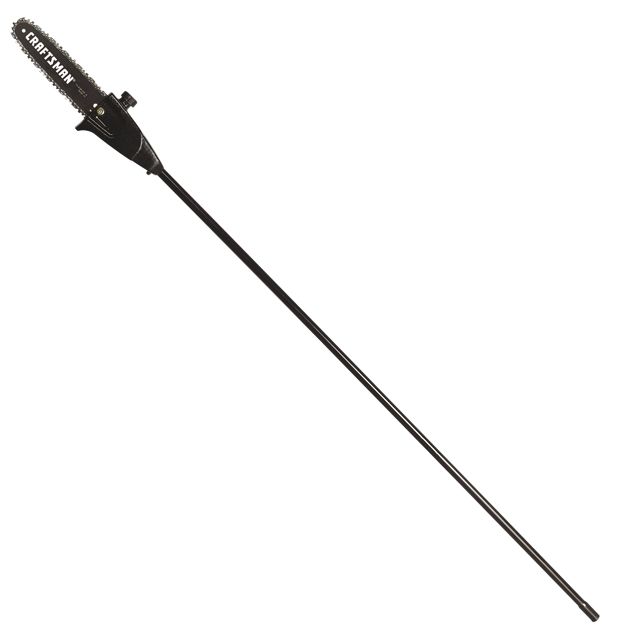
Model 358.792450
• Pruner Attachment
• Shoulder Strap
• Upper Shoulder Strap Clamp
• Lower Shoulder Strap Clamp (with
Spacer Tabs)
• Shoulder Strap Clamp Screws (2)
• Attachment Hanger
• Bar Sheath
• Chain Adjustment Tool (Bar Tool)
• Hex Wrench
• Bar and Chain Oil
Examine parts for damage. Do not
use damaged parts.
NOTE: If you need assistance, or find
parts missing or damaged, call
1-800-235-5878.
ASSEMBLY
,_WARNING: If received as-
sembled, repeat all steps to ensure
your unit is properly assembled and all
fasteners are secure.
TOOLS REQUIRED
• Hex wrench (provided)
INSTALLING PRUNER ATTACH-
MENT
CAUTION: When removing or instal-
ling attachments, place the unit on a
flat surface for stability.
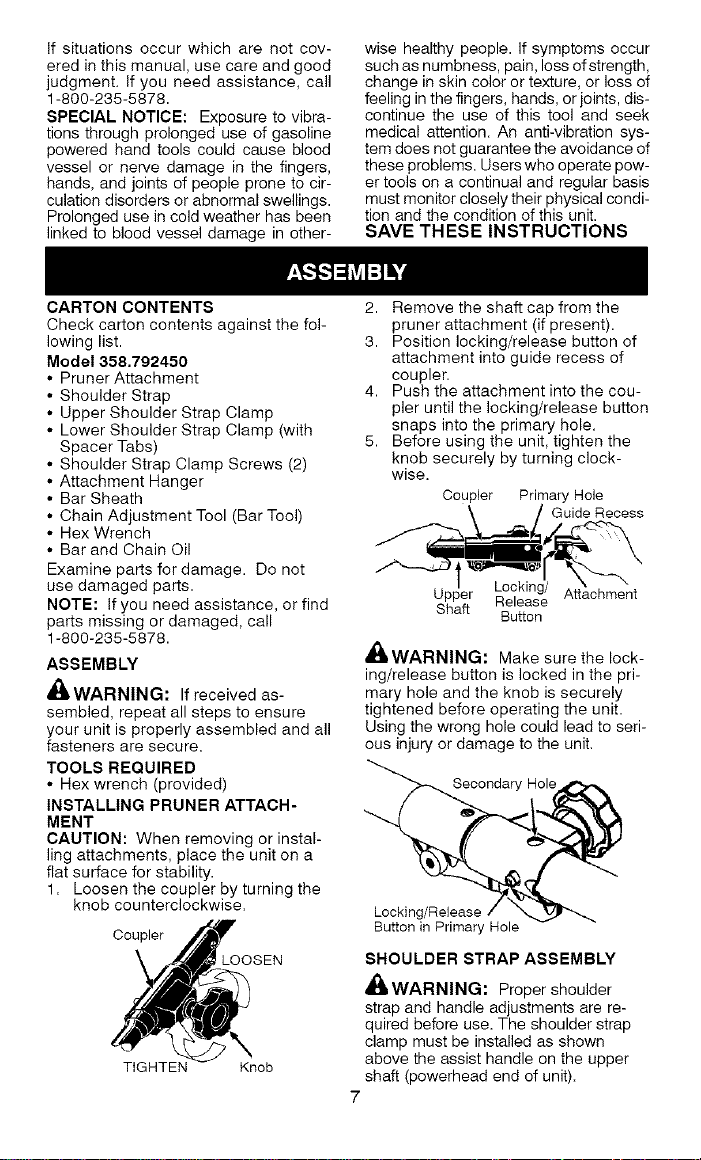
1. Loosen the coupler by turning the
knob counterclockwise.
Coupler
_OOSEN
TIGHTEN Knob
2. Remove the shaft cap from the
pruner attachment (if present).
3. Position locking/release button of
attachment into guide recess of
coupler.
4. Push the attachment into the cou-
pler until the locking/release button
snaps into the primary hole.
5. Before using the unit, tighten the
knob securely by turning clock-
wise.
Coupler Primary Hole
\ / Guide Recess
PP Release Attachment
Shaft
Button
,_WARNING: Make sure the lock-
ing/release button is locked in the pri-
mary hole and the knob is securely
tightened before operating the unit.
Using the wrong hole could lead to seri-
ous injury or damage to the unit.
Secondary Hole
Locking/Release
Button in Primary Hole
SHOULDER STRAP ASSEMBLY
_WARNING: Proper shoulder
strap and handle adjustments are re-
quired before use. The shoulder strap
clamp must be installed as shown
above the assist handle on the upper
shaft (powerhead end of unit).
7
Loading ...
Loading ...
Loading ...