Loading ...
Loading ...
Loading ...
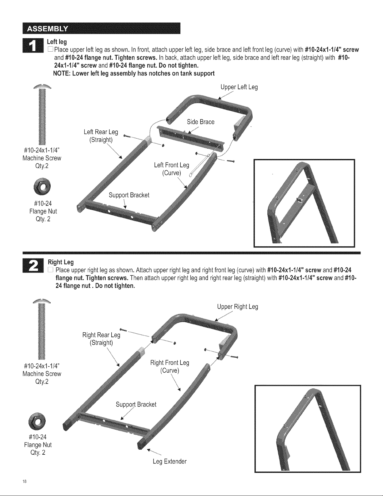
g Left leg
Place upper left leg as shown. In front, attach upper left leg, side brace and left front leg (curve) with #10-24×1-1/4" screw
and #10-24 flange nut. Tighten screws. In back, attach upper left leg, side brace and left rear leg (straight) with #10-
24×1-1/4" screw and #10-24 flange nut. Do not tighten.
NOTE: Lower left leg assembly has notches on tank support
Upper Left Leg
#10-24x1-1/4"
Machine Screw
Qty2
#10-24
Flange Nut
Qty 2
Left Rear Leg
(Straight) _
Support Bracket
Side Brace
Left Front Leg
(Curve)
Right Leg
} Place upper right leg as shown. Attach upper right leg and right front leg (curve) with #10-24x1-1/4" screw and #10-24
flange nut. Tighten screws. Then attach upper right leg and right rear leg (straight) with #10-24x1-1/4" screw and #10-
24 flange nut, Do not tighten,
Upper Right Leg
#10-24x1-1/4"
Machine Screw
Qty2
Right Rear Leg
(Straight) ..............o
"... _......
..
"X
" Right Front Leg
(Curve)
',\
Support Bracket
j_Z
#10-24
Flange Nut
Qty 2
Leg Extender
Loading ...
Loading ...
Loading ...