USER GUIDE & SERVICE MANUAL
3000 Series
●
3018CLR
●
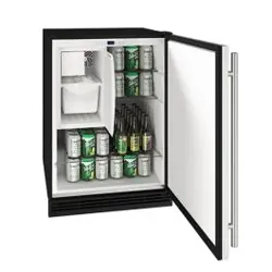
18” Clear Ice Machine (115V)
USER GUIDE & SERVICE MANUAL
u-line.com
Table of Contents
Intro
Safety
Safety and Warning
Disposal And Recycling
Installation
Environmental Requirements
Electrical
Side by Side Installation
Water Hookup
Drain
Drain Pump
Anti-Tip Bracket
General Installation
Integrated Panel Dimensions
Integrated Panel Installation
Grille Installation
Door Swing
Door Stop
Door Adjust
Maintenance
Cleaning
Cleaning Condenser
Extended Non-Use
Operating Instructions
First Use
Control Operation
Ice
Airflow and Product Loading
Service
Warranty
USER GUIDE
u-line.com
Introduction
WELCOME TO U-LINE
Congratulations on your U-Line purchase. Your product comes from a company with over ve decades of premium modular ice
making, refrigeration, and wine preservation experience. U-Line creates products focused on functionality, style, and inspired
innovations — paying close attention to even the smallest details. Applications include residential, outdoor, ADA height
compliant, marine, and commercial. Complete product categories include Beverage Centers, Wine Refrigerators, Ice Machines,
Refrigerators, Freezers, and Dispensers.
Our advanced refrigeration systems, large and exible capacities, and Built-In to Stand Out
®
clean integrated look allow you
to preserve the right product, in the right place, at the right temperature. Since 2014, U-Line has been part of the Middleby
family of brands. All products are designed, engineered, and assembled in Milwaukee, Wisconsin, USA, and select products
are available worldwide.
PRODUCT INFORMATION
Looking for additional information on your product? User Guides, Spec Sheets, CAD Drawings, Compliance Documentation,
and Product Warranty information are all available for reference and download at u-line.com.
PROPERTY DAMAGE / INJURY CONCERNS
In the unlikely event property damage or personal injury is suspected related to a U-Line product, please take the following
steps:
1. U-Line Customer Care must be contacted immediately at +1.414.354.0300.
2. Service or repairs performed on the unit without prior written approval from U-Line is not permitted. If the unit has been
altered or repaired in the eld without prior written approval from U-Line, claims will not be eligible.
GENERAL INQUIRIES
U-Line Corporation
8900 N. 55th Street
Milwaukee, Wisconsin 53223 USA
Monday - Friday 8:00 am to 4:30 pm CST
T: +1.414.354.0300
Email: sales@u-line.com
u-line.com
CONNECT WITH US
SERVICE & PARTS ASSISTANCE
Monday - Friday 8:00 am to 4:30 pm CST
T: +1.414.354.0300
Service Email: onlineservice@u-line.com
Parts Email: onlineparts@u-line.com
Designed, engineered and assembled in WI, USA
3
USER GUIDE
u-line.com
Safety and Warning
Safety and Warning
NOTICE
Please read all instructions before installing,
operating, or servicing the appliance.
Use this appliance for its intended purpose only and follow
these general precautions with those listed throughout this
guide:
SAFETY ALERT DEFINITIONS
Throughout this guide are safety items labeled with a
Danger, Warning, or Caution based on the risk type:
Danger means that failure to follow this safety
statement will result in severe personal injury or
death.
Warning means that failure to follow this safety
statement could result in serious personal injury
or death.
Caution means that failure to follow this safety
statement may result in minor or moderate
personal injury, property, or equipment damage.
This unit contains R600a (Isobutane) which is a
ammable hydrocarbon. It is safe for regular
use. Do not use sharp objects to expedite
defrosting. Do not service without consulting the
“R600a specications” section included in the
User Guide. Do not damage the refrigerant
circuit.
Service must be done by factory authorized
service personnel. Any parts shall be replaced
with like components. Failure to comply could
increase the risk of possible ignition due to
incorrect parts or improper service.
CALIFORNIA PROPOSITION 65
This product contains chemicals known to the
state of California to cause cancer and birth
defects or other reproductive harm.
www.P65warnings.CA.gov
This equipment is to be installed with adequate
backow protection to comply with applicable
federal, state and local codes.
DANGER
!
DANGER
!
WARNING
!
CAUTION
!
CAUTION
!
WARNING
!
4
USER GUIDE
u-line.com
Disposal and Recycling
Disposal and Recycling
RISK OF CHILD ENTRAPMENT. Before you throw
away your old refrigerator or freezer, take o
the doors and leave shelves in place so children
may not easily climb inside.
If the unit is being removed from service for disposal,
check and obey all federal, state, and local regulations
regarding the disposal and recycling of refrigeration
appliances, and follow these steps completely:
1. Remove all consumable contents from the unit.
2. Unplug the electrical cord from its socket.
3. Remove the door(s)/drawer(s).
DANGER
!
5
USER GUIDE
Environmental Requirements
u-line.com
Environmental Requirements
This model is intended for indoor/interior applications only
and is not to be used in installations that are open/
exposed to natural elements.
This unit is designed to operate between 50°F (10°C) and
100°F (38°C). Higher ambient temperatures may reduce
the unit’s ability to reach low temperatures and/or reduce
ice production on applicable models.
For best performance, keep the unit out of direct sunlight
and away from heat generating equipment.
In climates where high humidity and dew points are
present, condensation may appear on outside surfaces.
This is considered normal. The condensation will
evaporate when the humidity drops.
CAUTION
!
Damages caused by ambient temperatures of
40°F (4°C) or below are not covered by the
warranty.
6
USER GUIDE
Electrical
u-line.com
Electrical
WARNING
!
SHOCK HAZARD — Electrical Grounding
Required. Never attempt to repair or perform
maintenance on the unit until the electricity has
been disconnected.
Never remove the round grounding prong from
the plug and never use a two-prong grounding
adapter.
Altering, cutting or removing power cord,
removing power plug, or direct wiring can cause
serious injury, fire, loss of property and/or life,
and will void the warranty.
Never use an extension cord to connect power to
the unit.
Always keep your working area dry.
NOTICE
Electrical installation must observe all state and
local codes. This unit requires connection to a
grounded (three-prong), polarized receptacle
that has been placed by a qualified electrician.
The unit requires a grounded and polarized 115 VAC,
60 Hz, 15A power supply (normal household current). An
individual, properly grounded branch circuit or circuit
breaker is recommended. A GFCI (ground fault circuit
interrupter) is usually not required for fixed location
appliances and is not recommended for your unit because
it could be prone to nuisance tripping. However, be sure
to consult your local codes.
See CUTOUT & PRODUCT DIMENSIONS for recommended
receptacle location.
7
USER GUIDE
Side-by-Side Installation 1
u-line.com
SAFETY • INSTALLATION & INTEGRATION • OPERATING INSTRUCTIONS • MAINTENANCE • SERVICE
Side-by-Side Installation
OTHER SITE REQUIREMENTS
Side-by-Side Installation
Units must operate from separate, properly grounded
electrical receptacles placed according to each unit’s
electrical specifications requirements.
Cutout width for a side-by-side installation is the total of
the widths listed under Cutout Dimensions in each unit’s
Installation Guide. Each door can be opened individually
(one at a time) without interference.
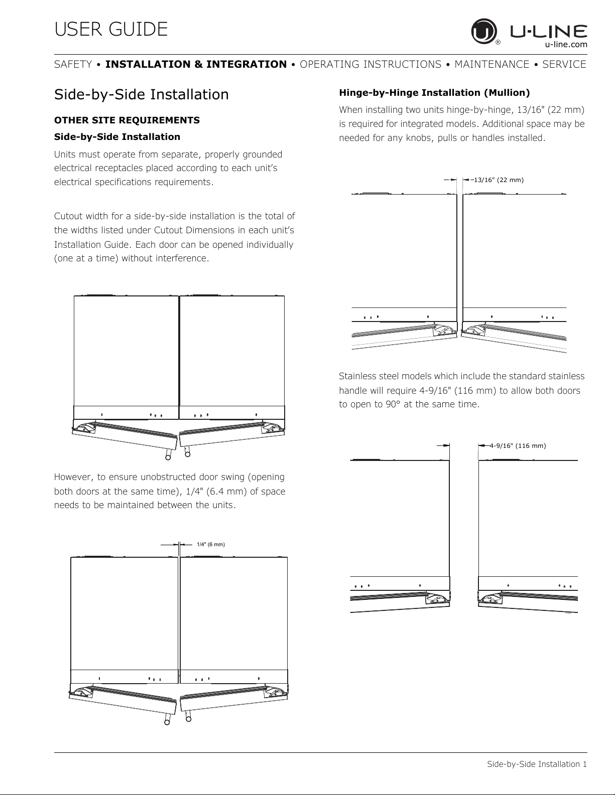
However, to ensure unobstructed door swing (opening
both doors at the same time), 1/4" (6.4 mm) of space
needs to be maintained between the units.
Hinge-by-Hinge Installation (Mullion)
When installing two units hinge-by-hinge, 13/16" (22 mm)
is required for integrated models. Additional space may be
needed for any knobs, pulls or handles installed.
Stainless steel models which include the standard stainless
handle will require 4-9/16" (116 mm) to allow both doors
to open to 90° at the same time.
1/4" (6 mm)
13/16" (22 mm)
4-9/16" (116 mm)
8
USER GUIDE
Door Swing 1
u-line.com
SAFETY • INSTALLATION & INTEGRATION • OPERATING INSTRUCTIONS • MAINTENANCE • SERVICE
Water Hookup
PREPARE PLUMBING
The water valve uses a standard 1/4" (6.35 mm)
compression fitting. U-Line recommends using accessory
water hook up kit – part # 80-54674-00. The kit includes a
10' (3 m) braided flexible water supply line and a brass
hose fitting.
WARNING
!
Prior to installation, determine if this product
contains a gravity style drain or factory installed
drain pump. Products without a drain pump may
only use a gravity style drain. Failure to connect
water supply or drain line connections properly
may result in water leakage, personal injury,
and/or property damage. Disconnect power and
turn off water to the unit before attempting to
alter these connections. These connections are
the responsibility of the owner and must be
connected per local plumbing code. If you are
uncertain of how to safely and properly install
this product, contact a licensed plumber.
Water Supply Connection
WARNING
!
Connect to potable water supply only.
CAUTION
!
Review, obey, and understand the local
plumbing codes before you install your unit.
Connect to the cold water supply. The water
pressure should be between 20 and 120 psi (138
and 827 kPa). The water line MUST
have a shut-
off valve on the supply line.
CAUTION
!
Do not use any plastic water supply line. The line
is under pressure at all times. Plastic may crack
or rupture with age and cause damage to your
home.
Do not use tape or joint compound when
attaching a braided flexible water supply line
that includes a rubber gasket. The gasket
provides an adequate seal – other materials
could cause blockage of the valve.
Failure to follow recommendations and
instructions may result in damage and/or harm,
flooding or void the product warranty.
CAUTION
!
Turn off water supply and disconnect electrical
supply to unit prior to installation.
Use caution when handling back panel. The
edges could be sharp.
1. Turn off water supply and disconnect electrical supply
to product prior to attempting installation.
2. Remove the grille/access panel in the front and the
back panel.
9
USER GUIDE
Door Swing 2
u-line.com
SAFETY • INSTALLATION & INTEGRATION • OPERATING INSTRUCTIONS • MAINTENANCE • SERVICE
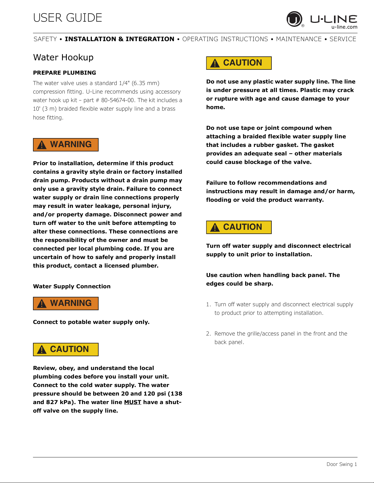
3. Locate water
valve in the front
of the unit and
thread water
supply line
through.
NOTICE
Route the water
supply line
through the unit so it does not come into contact
with any internal components other than the
solenoid valve. Normal operation creates some
vibration. A water supply line contacting an
internal component or cabinet wall can cause
excessive noise during operation or damage to
the line.
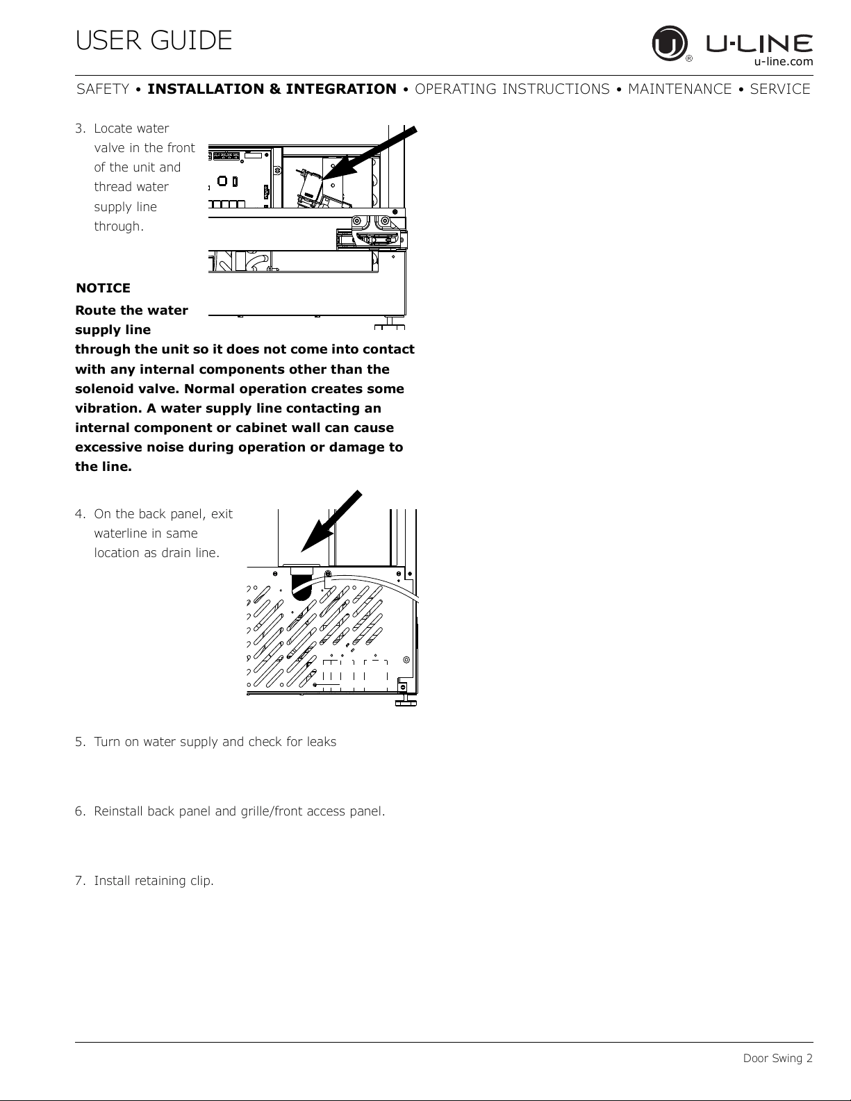
4. On the back panel, exit
waterline in same
location as drain line.
5. Turn on water supply and check for leaks
6. Reinstall back panel and grille/front access panel.
7. Install retaining clip.
10
USER GUIDE
Drain 1
u-line.com
SAFETY • INSTALLATION & INTEGRATION • OPERATING INSTRUCTIONS • MAINTENANCE • SERVICE
Drain
Model numbers including “-00” or “-07” do not include a
factory installed drain pump.
Model numbers including “-40” or “-47” include a factory
installed drain pump.
DRAIN CONNECTION
CAUTION
!
If your U-Line unit did not come with a factory
installed drain pump you must use a gravity
style drain connection. For assistance in
determining if your unit has a pump please
contact U-Line. The floor drain must be large
enough to accommodate drainage from all
attached drains. Follow these guidelines when
installing drain lines to prevent water from
flowing back into the ice maker storage bin and/
or potentially flowing onto the floor, which may
result in personal injury or property damage.
NOTICE
Drain can NOT be located directly below the unit.
Unit has a solid base that will not allow the unit
to drain below itself.
There is a possibility that hose connections may
have loosened during shipment.
Verify all connections and fittings are free from
leaks.
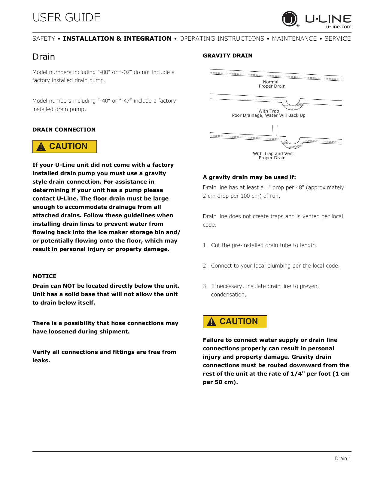
GRAVITY DRAIN
A gravity drain may be used if:
Drain line has at least a 1" drop per 48" (approximately
2 cm drop per 100 cm) of run.
Drain line does not create traps and is vented per local
code.
1. Cut the pre-installed drain tube to length.
2. Connect to your local plumbing per the local code.
3. If necessary, insulate drain line to prevent
condensation.
CAUTION
!
Failure to connect water supply or drain line
connections properly can result in personal
injury and property damage. Gravity drain
connections must be routed downward from the
rest of the unit at the rate of 1/4" per foot (1 cm
per 50 cm).
Normal
Proper Drain
With Trap
Poor Drainage, Water Will Back Up
With Trap and Vent
Proper Drain
11
USER GUIDE
Drain 2
u-line.com
SAFETY • INSTALLATION & INTEGRATION • OPERATING INSTRUCTIONS • MAINTENANCE • SERVICE
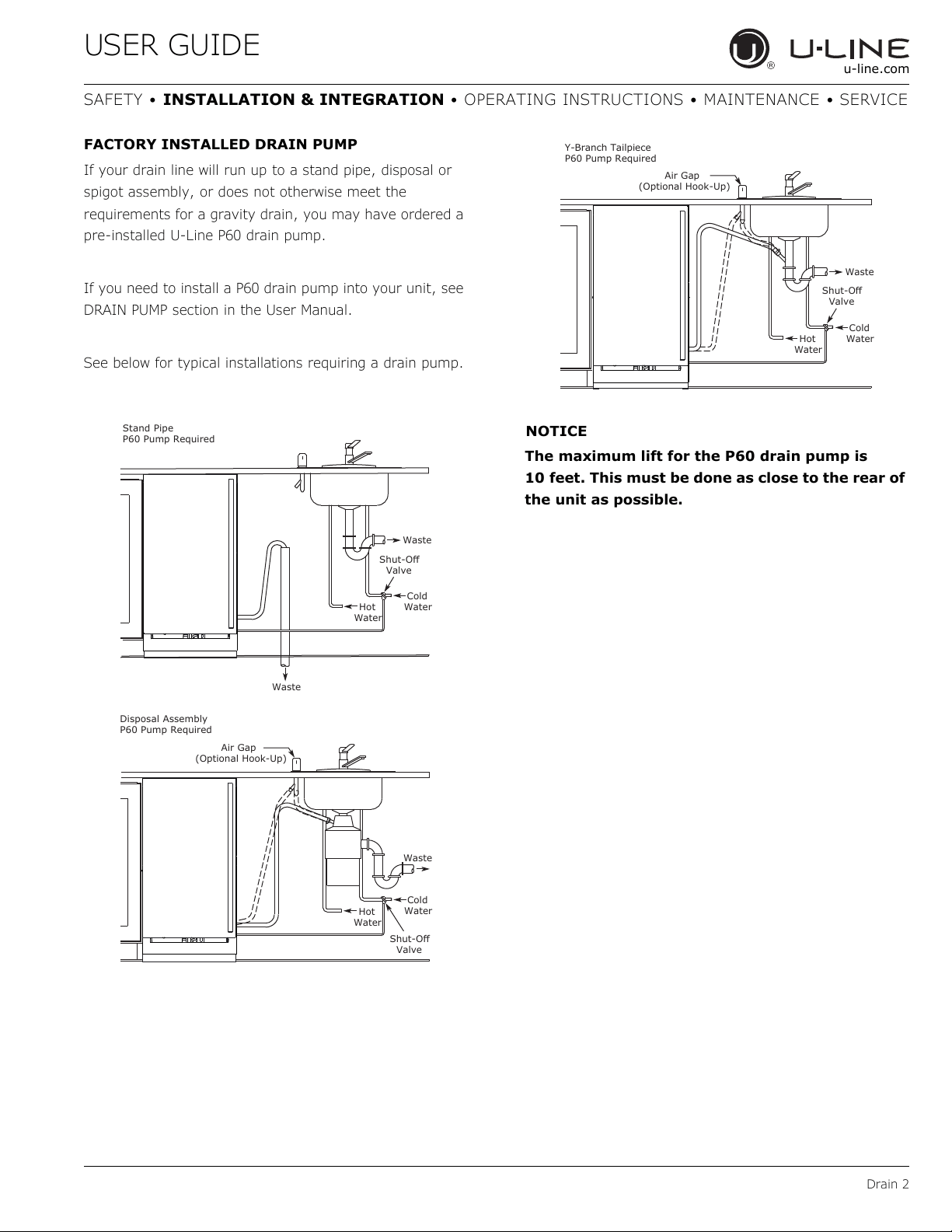
FACTORY INSTALLED DRAIN PUMP
If your drain line will run up to a stand pipe, disposal or
spigot assembly, or does not otherwise meet the
requirements for a gravity drain, you may have ordered a
pre-installed U-Line P60 drain pump.
If you need to install a P60 drain pump into your unit, see
DRAIN PUMP section in the User Manual.
See below for typical installations requiring a drain pump.
NOTICE
The maximum lift for the P60 drain pump is
10 feet. This must be done as close to the rear of
the unit as possible.
Cold
Water
Hot
Water
Waste
Waste
6KXW2ɞ
Valve
Stand Pipe
P60 Pump Required
Air Gap
(Optional Hook-Up)
Cold
Water
Hot
Water
Waste
6KXW2ɞ
Valve
Disposal Assembly
P60 Pump Required
Waste
Cold
Wate
r
6KXW2ɞ
Valve
Hot
Water
Air Gap
(Optional Hook-Up)
Y-Branch Tailpiece
P60 Pump Required
12
USER GUIDE
Drain Pump 1
u-line.com
SAFETY • INSTALLATION & INTEGRATION • OPERATING INSTRUCTIONS • MAINTENANCE • SERVICE
Drain Pump
NOTICE
PLEASE READ this instruction completely before
attempting to install or operate the unit.
Improper hook-up can result in substantial
property damage! If you are unsure of your
ability to safely connect the drain pump to the
unit, consult a licensed plumber for assistance.
Use these instructions to install the U-Line P60-
00 drain pump in the U-Line Clear Ice Machine
(unit). The drain pump should be installed
before installing the unit.
• The U-Line P60-00 drain pump is designed to be used
exclusively on the U-Line Clear Ice Machine and is UL
recognized only for use on the U-Line Clear Ice
Machine.
• U-Line Corporation assumes no warranties or
responsibility, whether express or implied, if the P60-00
drain pump is used on another ice machine or product
for which it is not UL recognized or listed.
• Modification of the P60-00 drain pump will void all
warranties.
NOTICE
Keep your proof of purchase for warranty
purposes.
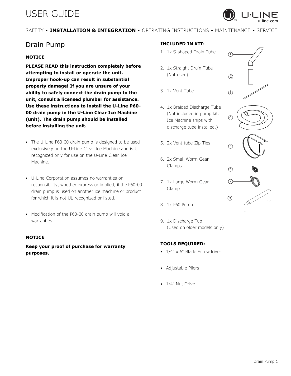
INCLUDED IN KIT:
1. 1x S-shaped Drain Tube
2. 1x Straight Drain Tube
(Not used)
3. 1x Vent Tube
4. 1x Braided Discharge Tube
(Not included in pump kit.
Ice Machine ships with
discharge tube installed.)
5. 2x Vent tube Zip Ties
6. 2x Small Worm Gear
Clamps
7. 1x Large Worm Gear
Clamp
8. 1x P60 Pump
9. 1x Discharge Tub
(Used on older models only)
TOOLS REQUIRED:
• 1/4" x 6" Blade Screwdriver
•Adjustable Pliers
•1/4" Nut Drive
1
3
4
5
6
7
2
9
13
USER GUIDE
Drain Pump 2
u-line.com
SAFETY • INSTALLATION & INTEGRATION • OPERATING INSTRUCTIONS • MAINTENANCE • SERVICE
INSTALLATION PROCEDURE
WARNING
!
To prevent accidental electrocution, make
certain that the floor surfaces surrounding the
unit are dry whenever power/electricity is
removed from, or applied to the unit.
1. Disconnect your unit from its electrical outlet/socket.
2. Using a screwdriver or 1/4" nut driver, remove the 9
screws from the back panel.
3. Remove the drain line/pipe from the storage bin drain
nipple. Save the clamp for pump installation.
CAUTION
!
To prevent damage to the pump, leave sufficient
space between leveling leg and pump.
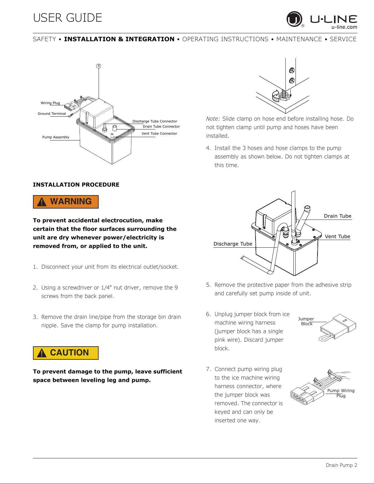
Note: Slide clamp on hose end before installing hose. Do
not tighten clamp until pump and hoses have been
installed.
4. Install the 3 hoses and hose clamps to the pump
assembly as shown below. Do not tighten clamps at
this time.
5. Remove the protective paper from the adhesive strip
and carefully set pump inside of unit.
6. Unplug jumper block from ice
machine wiring harness
(jumper block has a single
pink wire). Discard jumper
block.
7. Connect pump wiring plug
to the ice machine wiring
harness connector, where
the jumper block was
removed. The connector is
keyed and can only be
inserted one way.
Discharge Tube Connector
Drain Tube Connector
Vent Tube Connector
Pump Assembly
Ground Terminal
Wiring Plug
8
Drain Tube
Vent Tube
Discharge Tube
Jumper
Block
Pump Wiring
Plug
14
USER GUIDE
Drain Pump 3
u-line.com
SAFETY • INSTALLATION & INTEGRATION • OPERATING INSTRUCTIONS • MAINTENANCE • SERVICE
CAUTION
!
When working with tools inside of unit, be
careful so as not to nick or damage any
refrigerant lines/pipes or wires.
WARNING
!
The back panel serves as a guard. Do not put
your hands inside the ice machine cabinet or
attempt to touch any components except the
discharge tube during testing.
CAUTION
!
Failure to properly secure the vent tube will
result in water damage to the unit and
surrounding areas. Do not allow vent tube to
kink, bend or be obstructed in any way.
CAUTION
!
Vent tube must be straight and parallel to
insulated tubes. Do not over-tighten the plastic
tie wraps. Over-tightening can pinch vent tube
closed or cut into insulation.
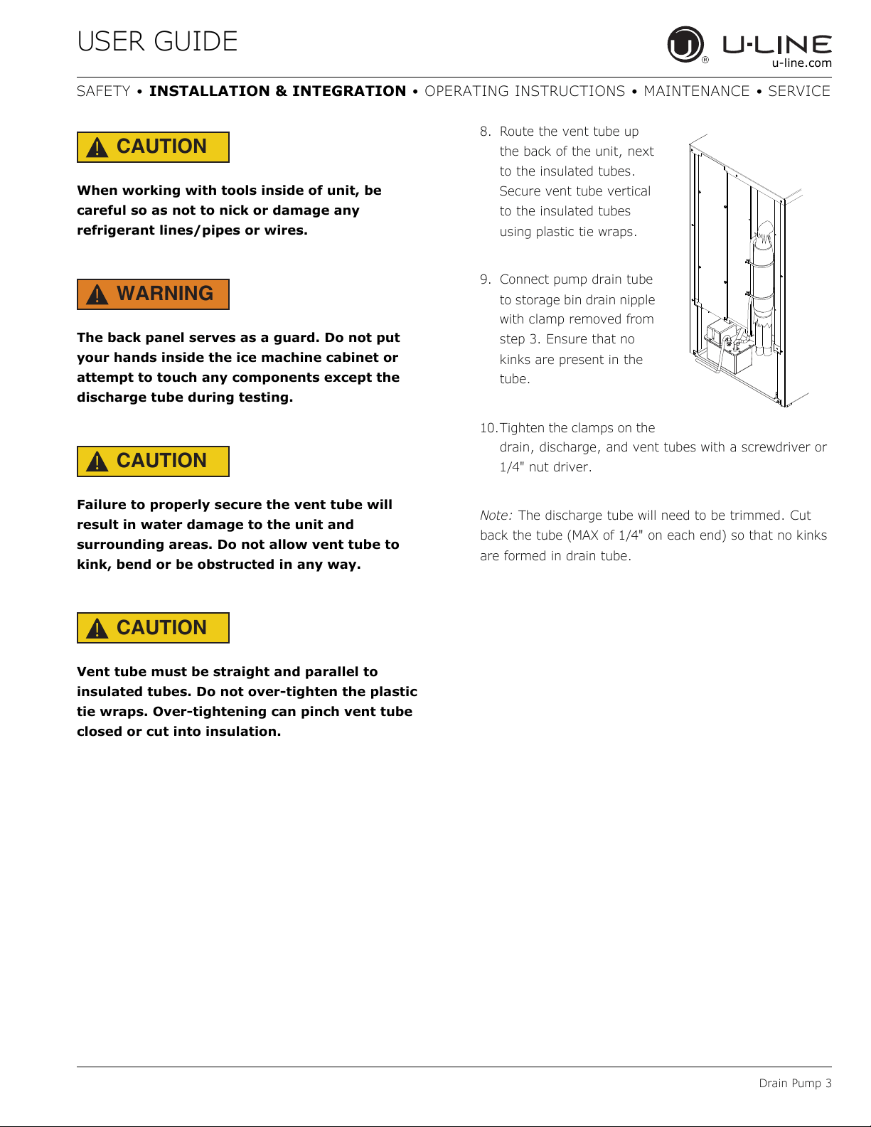
8. Route the vent tube up
the back of the unit, next
to the insulated tubes.
Secure vent tube vertical
to the insulated tubes
using plastic tie wraps.
9. Connect pump drain tube
to storage bin drain nipple
with clamp removed from
step 3. Ensure that no
kinks are present in the
tube.
10.Tighten the clamps on the
drain, discharge, and vent tubes with a screwdriver or
1/4" nut driver.
Note: The discharge tube will need to be trimmed. Cut
back the tube (MAX of 1/4" on each end) so that no kinks
are formed in drain tube.
15
USER GUIDE
Anti-Tip Bracket 1
u-line.com
SAFETY • INSTALLATION & INTEGRATION • OPERATING INSTRUCTIONS • MAINTENANCE • SERVICE
Anti-Tip Bracket
CAUTION
!
The anti-tip bracket must be installed to prevent
the unit from tipping when doors are fully
opened or excess weight is placed on the front of
the unit.
The anti-tip bracket has multiple mounting options.
Mounting will depend on your particular cabinet
configuration. Locate 3 #8x5/8" screws included with your
unit.
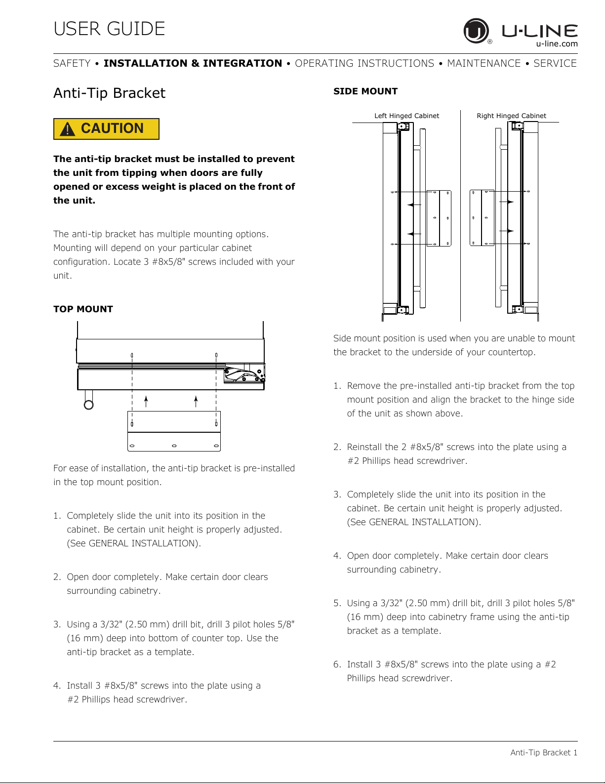
TOP MOUNT
For ease of installation, the anti-tip bracket is pre-installed
in the top mount position.
1. Completely slide the unit into its position in the
cabinet. Be certain unit height is properly adjusted.
(See GENERAL INSTALLATION).
2. Open door completely. Make certain door clears
surrounding cabinetry.
3. Using a 3/32" (2.50 mm) drill bit, drill 3 pilot holes 5/8"
(16 mm) deep into bottom of counter top. Use the
anti-tip bracket as a template.
4. Install 3 #8x5/8" screws into the plate using a
#2 Phillips head screwdriver.
SIDE MOUNT
Side mount position is used when you are unable to mount
the bracket to the underside of your countertop.
1. Remove the pre-installed anti-tip bracket from the top
mount position and align the bracket to the hinge side
of the unit as shown above.
2. Reinstall the 2 #8x5/8" screws into the plate using a
#2 Phillips head screwdriver.
3. Completely slide the unit into its position in the
cabinet. Be certain unit height is properly adjusted.
(See GENERAL INSTALLATION).
4. Open door completely. Make certain door clears
surrounding cabinetry.
5. Using a 3/32" (2.50 mm) drill bit, drill 3 pilot holes 5/8"
(16 mm) deep into cabinetry frame using the anti-tip
bracket as a template.
6. Install 3 #8x5/8" screws into the plate using a #2
Phillips head screwdriver.
Left Hinged Cabinet
Right Hinged Cabinet
16
USER GUIDE
General Installation 1
u-line.com
SAFETY • INSTALLATION & INTEGRATION • OPERATING INSTRUCTIONS • MAINTENANCE • SERVICE
General Installation
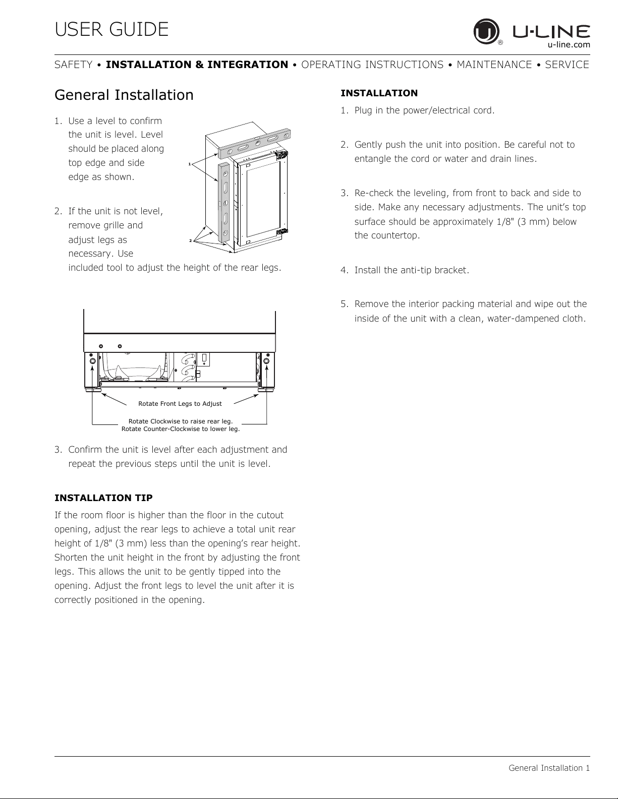
1. Use a level to confirm
the unit is level. Level
should be placed along
top edge and side
edge as shown.
2. If the unit is not level,
remove grille and
adjust legs as
necessary. Use
included tool to adjust the height of the rear legs.
3. Confirm the unit is level after each adjustment and
repeat the previous steps until the unit is level.
INSTALLATION TIP
If the room floor is higher than the floor in the cutout
opening, adjust the rear legs to achieve a total unit rear
height of 1/8" (3 mm) less than the opening’s rear height.
Shorten the unit height in the front by adjusting the front
legs. This allows the unit to be gently tipped into the
opening. Adjust the front legs to level the unit after it is
correctly positioned in the opening.
INSTALLATION
1. Plug in the power/electrical cord.
2. Gently push the unit into position. Be careful not to
entangle the cord or water and drain lines.
3. Re-check the leveling, from front to back and side to
side. Make any necessary adjustments. The unit’s top
surface should be approximately 1/8" (3 mm) below
the countertop.
4. Install the anti-tip bracket.
5. Remove the interior packing material and wipe out the
inside of the unit with a clean, water-dampened cloth.
2
1
Rotate Clockwise to raise rear leg.
Rotate Counter-Clockwise to lower leg.
Rotate Front Legs to Adjust
17
USER GUIDE
Integrated Panel Dimensions 1
u-line.com
SAFETY • INSTALLATION & INTEGRATION • OPERATING INSTRUCTIONS • MAINTENANCE • SERVICE
Integrated Panel Dimensions
Metric measurements rounded and optimized.
INTEGRATED PANEL
NOTICE
Due to differences in surrounding cabinetry the
panel may not perfectly align with door. The
procedure below is designed to provide a
finished integrated panel that seamlessly
integrates with surrounding cabinetry.
Panel Preparation
A full integrated door panel completely covers the door
frame and provides a built-in appearance.
NOTICE
The door panel must not weigh more than 20 lbs
(10 kg).
It is important to ensure that all drilled holes are
drilled to the correct depth in order to avoid
splits in the wood when hardware is installed.
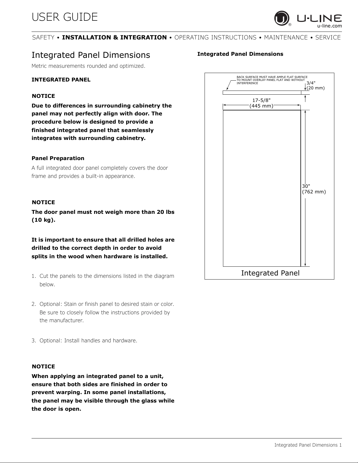
1. Cut the panels to the dimensions listed in the diagram
below.
2. Optional: Stain or finish panel to desired stain or color.
Be sure to closely follow the instructions provided by
the manufacturer.
3. Optional: Install handles and hardware.
NOTICE
When applying an integrated panel to a unit,
ensure that both sides are finished in order to
prevent warping. In some panel installations,
the panel may be visible through the glass while
the door is open.
Integrated Panel Dimensions
BACK SURFACE MUST HAVE AMPLE FLAT SURFACE
TO MOUNT OVERLAY PANEL FLAT AND WITHOUT
INTERFERENCE
3/4"
(20 mm)
Integrated Panel
17-5/8"
(445 mm)
30"
(762 mm)
18
USER GUIDE
Integrated Panel Dimensions 2
u-line.com
SAFETY • INSTALLATION & INTEGRATION • OPERATING INSTRUCTIONS • MAINTENANCE • SERVICE
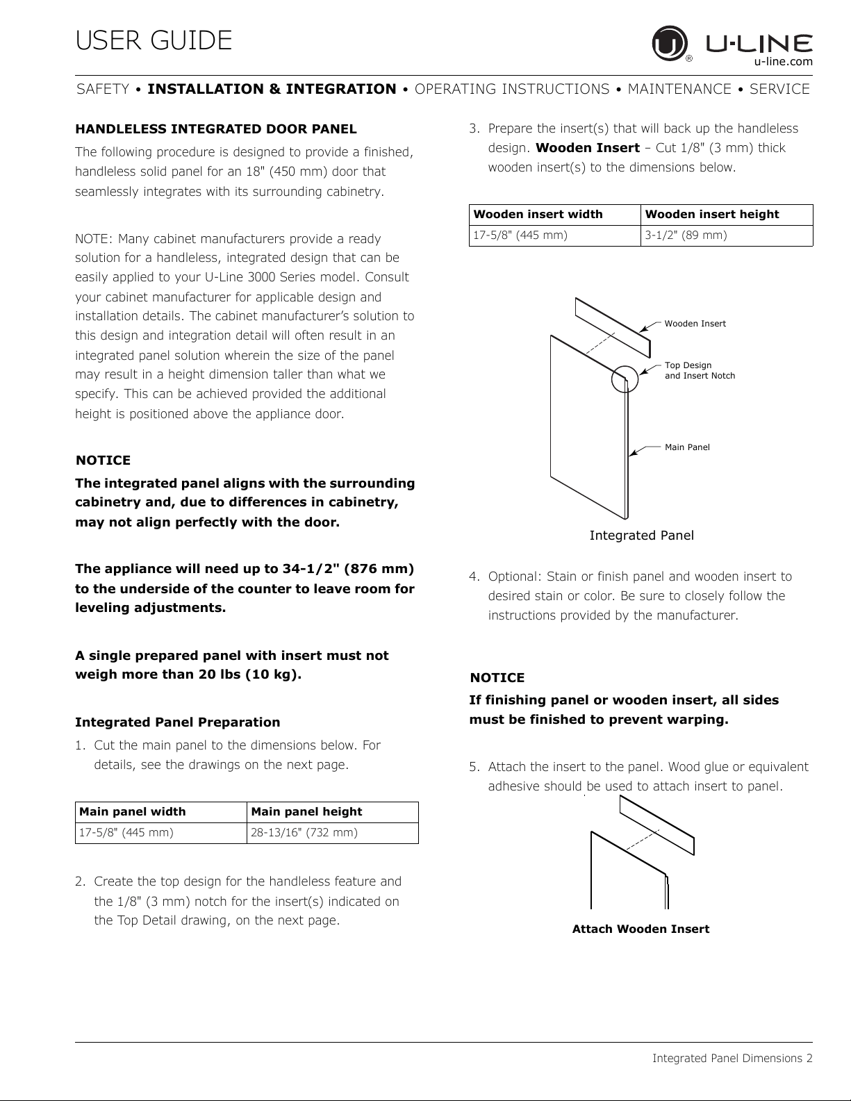
HANDLELESS INTEGRATED DOOR PANEL
The following procedure is designed to provide a finished,
handleless solid panel for an 18" (450 mm) door that
seamlessly integrates with its surrounding cabinetry.
NOTE: Many cabinet manufacturers provide a ready
solution for a handleless, integrated design that can be
easily applied to your U-Line 3000 Series model. Consult
your cabinet manufacturer for applicable design and
installation details. The cabinet manufacturer’s solution to
this design and integration detail will often result in an
integrated panel solution wherein the size of the panel
may result in a height dimension taller than what we
specify. This can be achieved provided the additional
height is positioned above the appliance door.
NOTICE
The integrated panel aligns with the surrounding
cabinetry and, due to differences in cabinetry,
may not align perfectly with the door.
The appliance will need up to 34-1/2" (876 mm)
to the underside of the counter to leave room for
leveling adjustments.
A single prepared panel with insert must not
weigh more than 20 lbs (10 kg).
Integrated Panel Preparation
1. Cut the main panel to the dimensions below. For
details, see the drawings on the next page.
2. Create the top design for the handleless feature and
the 1/8" (3 mm) notch for the insert(s) indicated on
the Top Detail drawing, on the next page.
3. Prepare the insert(s) that will back up the handleless
design. Wooden Insert – Cut 1/8" (3 mm) thick
wooden insert(s) to the dimensions below.
4. Optional: Stain or finish panel and wooden insert to
desired stain or color. Be sure to closely follow the
instructions provided by the manufacturer.
NOTICE
If finishing panel or wooden insert, all sides
must be finished to prevent warping.
5. Attach the insert to the panel. Wood glue or equivalent
adhesive should be used to attach insert to panel.
Main panel width Main panel height
17-5/8" (445 mm) 28-13/16" (732 mm)
Wooden insert width Wooden insert height
17-5/8" (445 mm) 3-1/2" (89 mm)
Top Design
and Insert Notch
Wooden Insert
Main Panel
Integrated Panel
Attach Wooden Insert
19
USER GUIDE
Integrated Panel Dimensions 3
u-line.com
SAFETY • INSTALLATION & INTEGRATION • OPERATING INSTRUCTIONS • MAINTENANCE • SERVICE
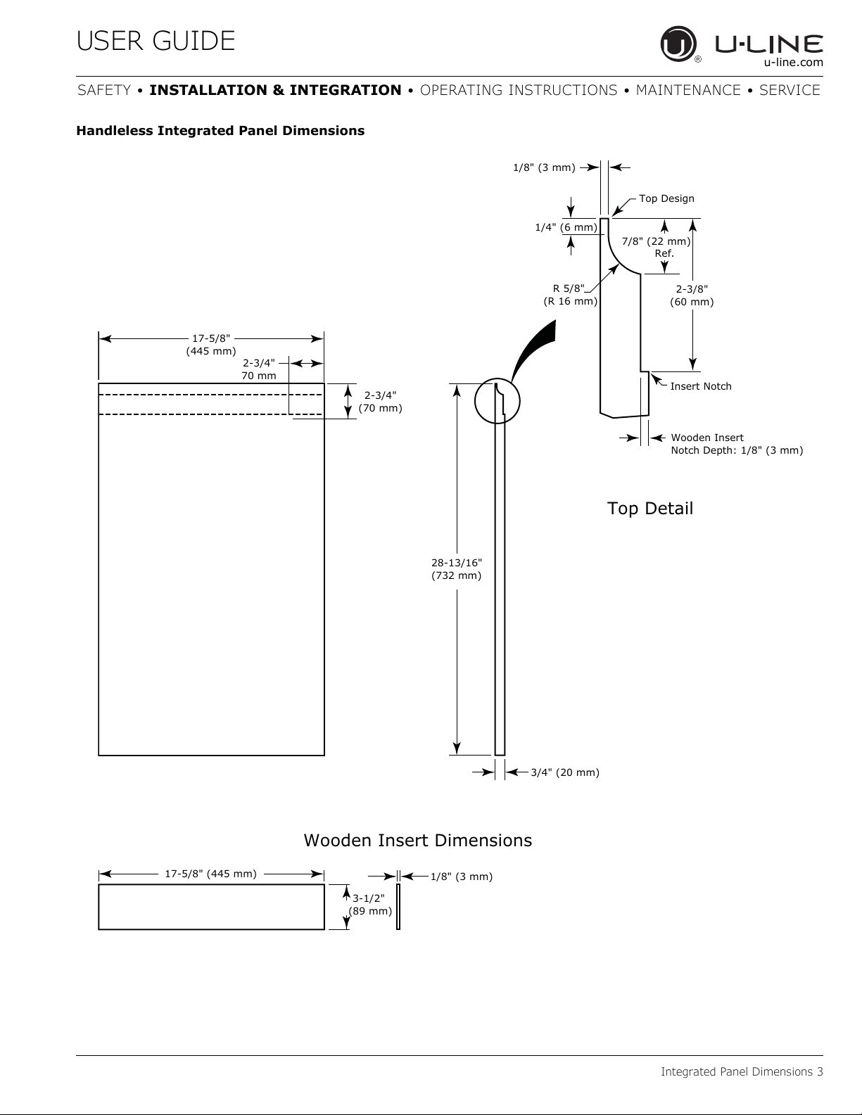
Handleless Integrated Panel Dimensions
3/4" (20 mm)
28-13/16"
(732 mm)
2-3/4"
(70 mm)
2-3/4"
70 mm
R 5/8"
(R 16 mm)
1/8" (3 mm)
1/4" (6 mm)
Wooden Insert
Notch Depth: 1/8" (3 mm)
2-3/8"
(60 mm)
7/8" (22 mm)
Ref.
Top Detail
Insert Notch
Top Design
1/8" (3 mm)
3-1/2"
(89 mm)
17-5/8" (445 mm)
Wooden Insert Dimensions
17-5/8"
(445 mm)
20
USER GUIDE
Integrated Panel Dimensions 4
u-line.com
SAFETY • INSTALLATION & INTEGRATION • OPERATING INSTRUCTIONS • MAINTENANCE • SERVICE
EXTENDED INTEGRATED PANEL
NOTICE
Due to differences in surrounding cabinetry the
panel may not perfectly align with door. The
procedure below is designed to provide a
finished panel that seamlessly integrates with
surrounding cabinetry.
Panel Preparation
An extended integrated panel can be used to maintain
alignment with an adjacent extended cabinet height or a
reduced toe-kick/grille application.
1. Cut the panels to the dimensions listed in the
appropriate diagram on the next page.
2. Optional: Stain or finish panel to desired stain or color.
Be sure to closely follow the instructions provided by
the manufacturer.
3. Optional: Install handles and hardware.
NOTICE
The door panel must not weigh more than 20 lbs
(10 kg).
It is important to ensure that all drilled holes are
drilled to the correct depth in order to avoid
splits in the wood when hardware is installed.
Appliance will need up to 34-1/2" (876 mm) to
the underside of the counter to leave room for
leveling adjustments.
When applying an integrated panel to a unit,
ensure that both sides are finished in order to
prevent warping. In some installations, the
panel may be visible through the glass while the
door is open.
21
USER GUIDE
Integrated Panel Dimensions 5
u-line.com
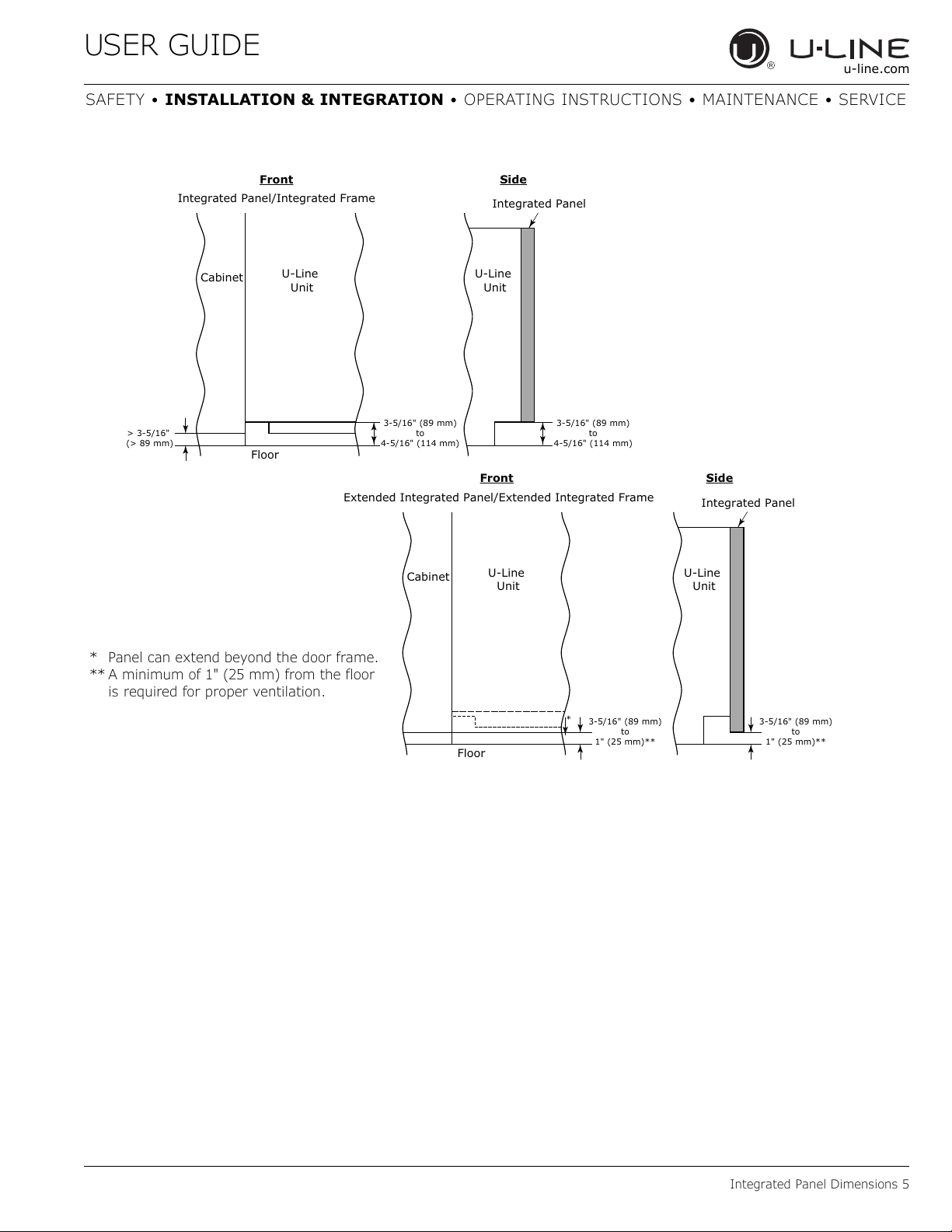
SAFETY • INSTALLATION & INTEGRATION • OPERATING INSTRUCTIONS • MAINTENANCE • SERVICE
3-5/16" (89 mm)
to
4-5/16" (114 mm)
U-Line
Unit
U-Line
Unit
Integrated Panel
Integrated Panel/Integrated Frame
Front
Side
Front Side
3-5/16" (89 mm)
to
4-5/16" (114 mm)
Floor
Cabinet
> 3-5/16"
(> 89 mm)
3-5/16" (89 mm)
to
1" (25 mm)**
U-Line
Unit
Extended Integrated Panel/Extended Integrated Frame
Floor
Cabinet
3-5/16" (89 mm)
to
1" (25 mm)**
*
U-Line
Unit
Integrated Panel
* Panel can extend beyond the door frame.
** A minimum of 1" (25 mm) from the floor
is required for proper ventilation.
22
USER GUIDE
Integrated Panel Dimensions 6
u-line.com
SAFETY • INSTALLATION & INTEGRATION • OPERATING INSTRUCTIONS • MAINTENANCE • SERVICE
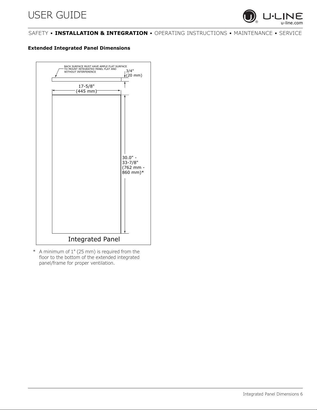
Extended Integrated Panel Dimensions
BACK SURFACE MUST HAVE AMPLE FLAT SURFACE
TO MOUNT INTEGRATED PANEL FLAT AND
WITHOUT INTERFERENCE
3/4"
(20 mm)
Integrated Panel
17-5/8"
(445 mm)
30.0" -
33-7/8"
(762 mm -
860 mm)*
* A minimum of 1" (25 mm) is required from the
floor to the bottom of the extended integrated
panel/frame for proper ventilation.
23
USER GUIDE
Integrated Panel Installation 1
u-line.com
SAFETY • INSTALLATION & INTEGRATION • OPERATING INSTRUCTIONS • MAINTENANCE • SERVICE
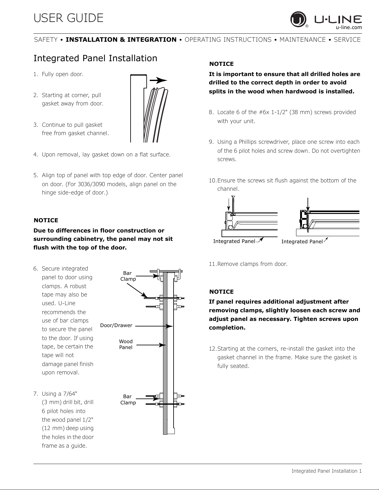
Integrated Panel Installation
1. Fully open door.
2. Starting at corner, pull
gasket away from door.
3. Continue to pull gasket
free from gasket channel.
4. Upon removal, lay gasket down on a flat surface.
5. Align top of panel with top edge of door. Center panel
on door. (For 3036/3090 models, align panel on the
hinge side-edge of door.)
NOTICE
Due to differences in floor construction or
surrounding cabinetry, the panel may not sit
flush with the top of the door.
6. Secure integrated
panel to door using
clamps. A robust
tape may also be
used. U-Line
recommends the
use of bar clamps
to secure the panel
to the door. If using
tape, be certain the
tape will not
damage panel finish
upon removal.
7. Using a 7/64"
(3 mm) drill bit, drill
6 pilot holes into
the wood panel 1/2"
(12 mm) deep using
the holes in
the door
frame as a guide.
NOTICE
It is important to ensure that all drilled holes are
drilled to the correct depth in order to avoid
splits in the wood when hardwood is installed.
8. Locate 6 of the #6x 1-1/2" (38 mm) screws provided
with your unit.
9. Using a Phillips screwdriver, place one screw into each
of the 6 pilot holes and screw down. Do not overtighten
screws.
10.Ensure the screws sit flush against the bottom of the
channel.
11.Remove clamps from door.
NOTICE
If panel requires additional adjustment after
removing clamps, slightly loosen each screw and
adjust panel as necessary. Tighten screws upon
completion.
12.Starting at the corners, re-install the gasket into the
gasket channel in the frame. Make sure the gasket is
fully seated.
Wood
Panel
Door/Drawer
Bar
Clamp
Bar
Clamp
Integrated Panel
Integrated Panel
24
USER GUIDE
Grille Installation
u-line.com
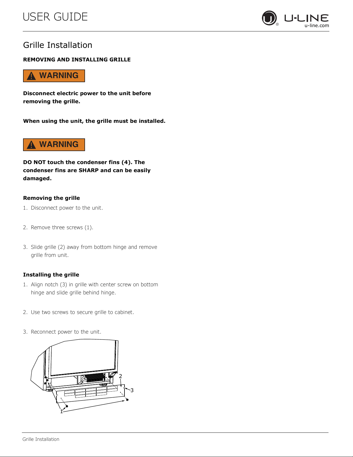
Grille Installation
REMOVING AND INSTALLING GRILLE
WARNING
!
Disconnect electric power to the unit before
removing the grille.
When using the unit, the grille must be installed.
WARNING
!
DO NOT touch the condenser fins (4). The
condenser fins are SHARP and can be easily
damaged.
Removing the grille
1. Disconnect power to the unit.
2. Remove three screws (1).
3. Slide grille (2) away from bottom hinge and remove
grille from unit.
Installing the grille
1. Align notch (3) in grille with center screw on bottom
hinge and slide grille behind hinge.
2. Use two screws to secure grille to cabinet.
3. Reconnect power to the unit.
2
3
1
25
USER GUIDE
Door Swing 1
u-line.com
SAFETY • INSTALLATION & INTEGRATION • OPERATING INSTRUCTIONS • MAINTENANCE • SERVICE
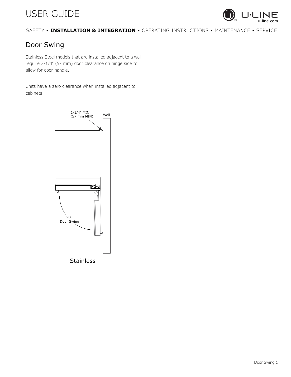
Door Swing
Stainless Steel models that are installed adjacent to a wall
require 2-1/4” (57 mm) door clearance on hinge side to
allow for door handle.
Units have a zero clearance when installed adjacent to
cabinets.
Wall
90°
Door Swing
2-1/4" MIN
(57 mm MIN)
Stainless
26
USER GUIDE
Door Stop 1
u-line.com
SAFETY • INSTALLATION & INTEGRATION • OPERATING INSTRUCTIONS • MAINTENANCE • SERVICE
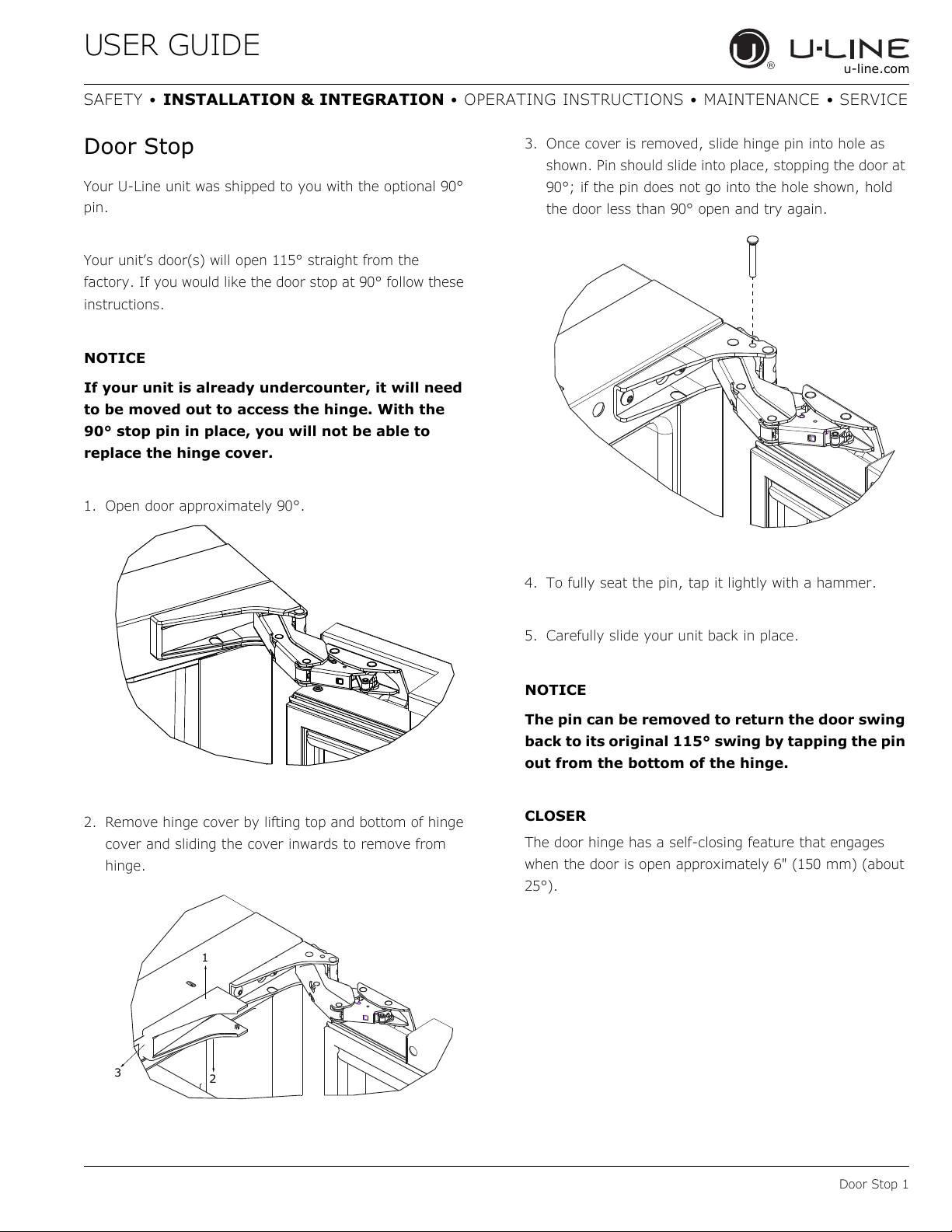
Door Stop
Your U-Line unit was shipped to you with the optional 90°
pin.
Your unit’s door(s) will open 115° straight from the
factory. If you would like the door stop at 90° follow these
instructions.
NOTICE
If your unit is already undercounter, it will need
to be moved out to access the hinge. With the
90° stop pin in place, you will not be able to
replace the hinge cover.
1. Open door approximately 90°.
2. Remove hinge cover by lifting top and bottom of hinge
cover and sliding the cover inwards to remove from
hinge.
3. Once cover is removed, slide hinge pin into hole as
shown. Pin should slide into place, stopping the door at
90°; if the pin does not go into the hole shown, hold
the door less than 90° open and try again.
4. To fully seat the pin, tap it lightly with a hammer.
5. Carefully slide your unit back in place.
NOTICE
The pin can be removed to return the door swing
back to its original 115° swing by tapping the pin
out from the bottom of the hinge.
CLOSER
The door hinge has a self-closing feature that engages
when the door is open approximately 6" (150 mm) (about
25°).
1
3
2
27
USER GUIDE
Door Adjustments 1
u-line.com
SAFETY • INSTALLATION & INTEGRATION • OPERATING INSTRUCTIONS • MAINTENANCE • SERVICE
Door Adjustments
DOOR ALIGNMENT AND ADJUSTMENT
Align and adjust the door if it is not level or is not sealing
properly. If the door is not sealed, the unit may not cool
properly, or excessive frost or condensation may form in
the interior.
NOTICE
Properly aligned, the door’s gasket should be
firmly in contact with the cabinet all the way
around the door (no gaps). Carefully examine
the door’s gasket to ensure that it is firmly in
contact with the cabinet. Also make sure the
door gasket is not pinched on the hinge side of
the door.
CAUTION
!
Do not attempt to use the door to raise or pivot
your unit. This would put excessive stress on the
hinge system.
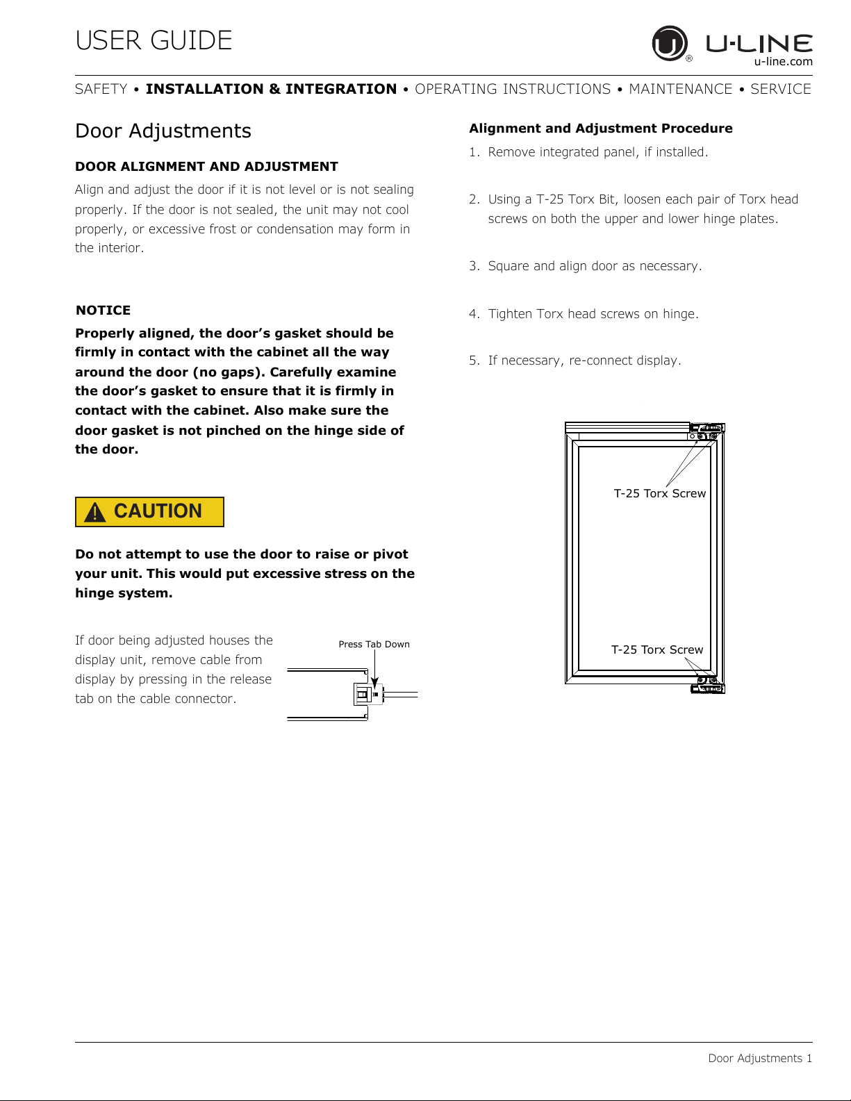
If door being adjusted houses the
display unit, remove cable from
display by pressing in the release
tab on the cable connector.
Alignment and Adjustment Procedure
1. Remove integrated panel, if installed.
2. Using a T-25 Torx Bit, loosen each pair of Torx head
screws on both the upper and lower hinge plates.
3. Square and align door as necessary.
4. Tighten Torx head screws on hinge.
5. If necessary, re-connect display.
.
Press Tab Down
T-25 Torx Screw
T-25 Torx Screw
28
USER GUIDE
First Use 1
u-line.com
SAFETY • INSTALLATION & INTEGRATION • OPERATING INSTRUCTIONS • MAINTENANCE • SERVICE
First Use
All U-Line controls are preset at the factory. Initial startup
requires no adjustments.
NOTICE
U-Line recommends discarding the ice produced
during the first two to three hours of operation
to avoid possible dirt or scale that may dislodge
from the water line.
When plugged in, the unit will begin operating under the
factory default setting. Follow the on screen prompt for
language selection and temperature units.
To turn the unit off, press and hold for 5 seconds and
release. The display will show a countdown to switching the
unit off.
To power your unit on, simply press and the unit will
immediately switch on.
29
USER GUIDE
Control Operation 1
u-line.com
SAFETY • INSTALLATION & INTEGRATION • OPERATING INSTRUCTIONS • MAINTENANCE • SERVICE
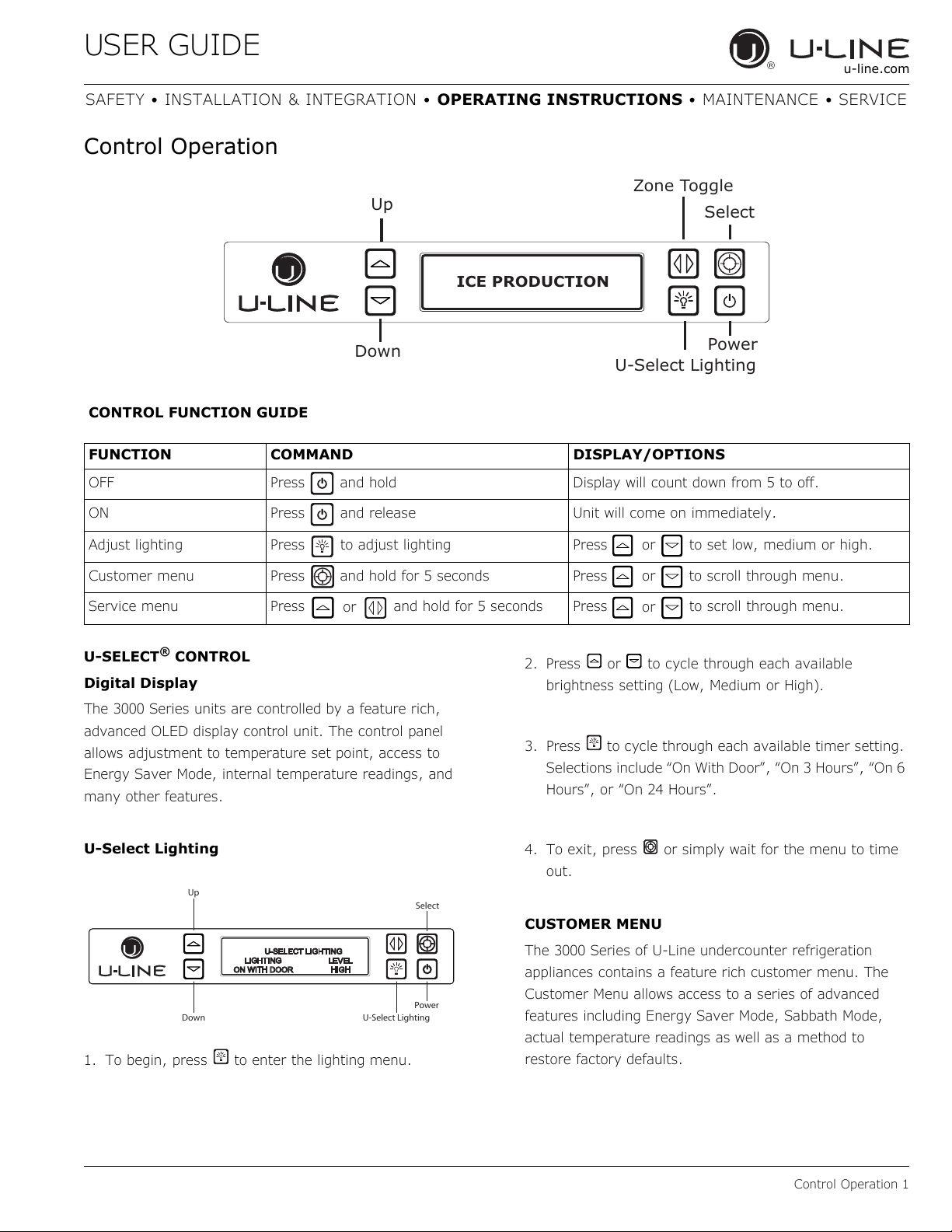
Control Operation
U-SELECT
®
CONTROL
Digital Display
The 3000 Series units are controlled by a feature rich,
advanced OLED display control unit. The control panel
allows adjustment to temperature set point, access to
Energy Saver Mode, internal temperature readings, and
many other features.
U-Select Lighting
1. To begin, press to enter the lighting menu.
2. Press or to cycle through each available
brightness setting (Low, Medium or High).
3. Press to cycle through each available timer setting.
Selections include “On With Door”, “On 3 Hours”, “On 6
Hours”, or “On 24 Hours”.
4. To exit, press or simply wait for the menu to time
out.
CUSTOMER MENU
The 3000 Series of U-Line undercounter refrigeration
appliances contains a feature rich customer menu. The
Customer Menu allows access to a series of advanced
features including Energy Saver Mode, Sabbath Mode,
actual temperature readings as well as a method to
restore factory defaults.
Up
Select
Zone Toggle
Down
Power
ICE PRODUCTION
U-Select Lighting
CONTROL FUNCTION GUIDE
FUNCTION COMMAND DISPLAY/OPTIONS
OFF Press and hold Display will count down from 5 to off.
ON Press and release Unit will come on immediately.
Adjust lighting Press to adjust lighting Press to set low, medium or high.
Customer menu Press and hold for 5 seconds Press to scroll through menu.
Service menu Press and hold for 5 seconds Press to scroll through menu.
or
or
or
or
Up
Select
Down
U-Select Lighting
Power
30
USER GUIDE
Control Operation 2
u-line.com
SAFETY • INSTALLATION & INTEGRATION • OPERATING INSTRUCTIONS • MAINTENANCE • SERVICE
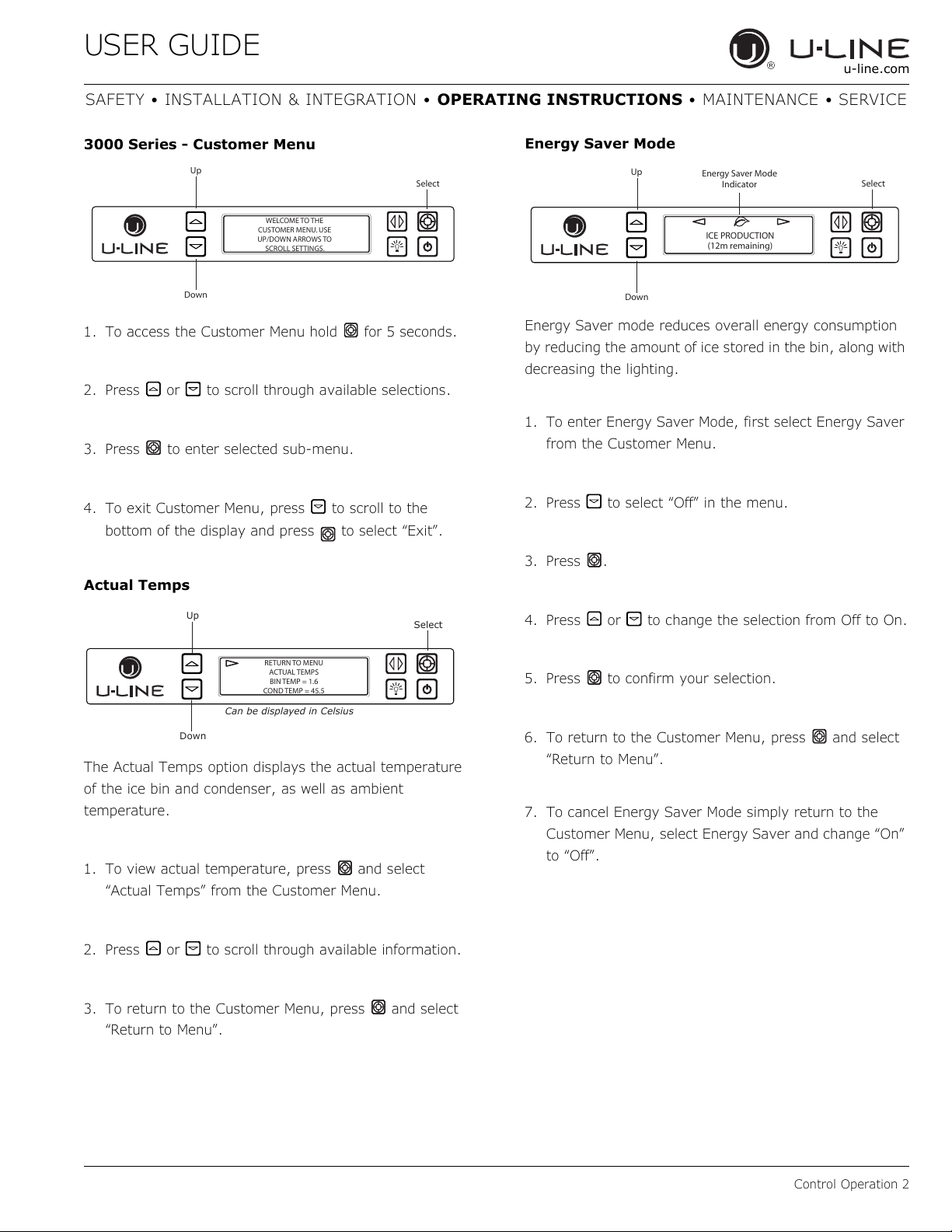
3000 Series - Customer Menu
1. To access the Customer Menu hold for 5 seconds.
2. Press or to scroll through available selections.
3. Press to enter selected sub-menu.
4. To exit Customer Menu, press to scroll to the
bottom of the display and press to select “Exit”.
Actual Temps
The Actual Temps option displays the actual temperature
of the ice bin and condenser, as well as ambient
temperature.
1. To view actual temperature, press and select
“Actual Temps” from the Customer Menu.
2. Press or to scroll through available information.
3. To return to the Customer Menu, press and select
“Return to Menu”.
Energy Saver Mode
Energy Saver mode reduces overall energy consumption
by reducing the amount of ice stored in the bin, along with
decreasing the lighting.
1. To enter Energy Saver Mode, first select Energy Saver
from the Customer Menu.
2. Press to select “Off” in the menu.
3. Press .
4. Press or to change the selection from Off to On.
5. Press to confirm your selection.
6. To return to the Customer Menu, press and select
“Return to Menu”.
7. To cancel Energy Saver Mode simply return to the
Customer Menu, select Energy Saver and change “On”
to “Off”.
Up
Select
Down
WELCOME TO THE
CUSTOMER MENU. USE
UP/DOWN ARROWS TO
SCROLL SETTINGS.
Up
Select
Down
RETURN TO MENU
ACTUAL TEMPS
BIN TEMP = 1.6
COND TEMP = 45.5
Can be displayed in Celsius
Up
Select
Down
Energy Saver Mode
Indicator
ICE PRODUCTION
(12m remaining)
31
USER GUIDE
Control Operation 3
u-line.com
SAFETY • INSTALLATION & INTEGRATION • OPERATING INSTRUCTIONS • MAINTENANCE • SERVICE
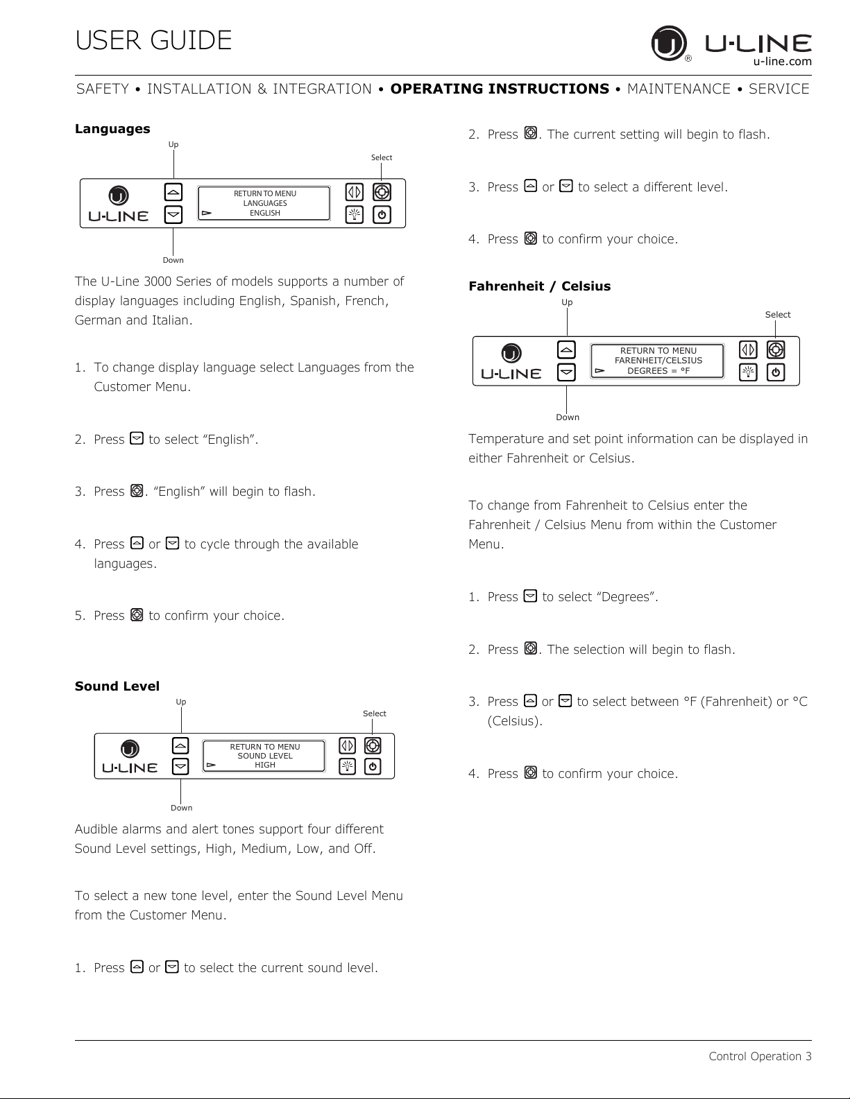
Languages
The U-Line 3000 Series of models supports a number of
display languages including English, Spanish, French,
German and Italian.
1. To change display language select Languages from the
Customer Menu.
2. Press to select “English”.
3. Press . “English” will begin to flash.
4. Press or to cycle through the available
languages.
5. Press to confirm your choice.
Sound Level
Audible alarms and alert tones support four different
Sound Level settings, High, Medium, Low, and Off.
To select a new tone level, enter the Sound Level Menu
from the Customer Menu.
1. Press
or
to select the current sound level.
2. Press . The current setting will begin to flash.
3. Press or to select a different level.
4. Press to confirm your choice.
Fahrenheit / Celsius
Temperature and set point information can be displayed in
either Fahrenheit or Celsius.
To change from Fahrenheit to Celsius enter the
Fahrenheit / Celsius Menu from within the Customer
Menu.
1. Press to select “Degrees”.
2. Press . The selection will begin to flash.
3. Press or to select between °F (Fahrenheit) or °C
(Celsius).
4. Press to confirm your choice.
Up
Select
Down
RETURN TO MENU
LANGUAGES
ENGLISH
Up
Select
Down
RETURN TO MENU
SOUND LEVEL
HIGH
Up
Select
Down
RETURN TO MENU
FARENHEIT/CELSIUS
DEGREES = °F
32
USER GUIDE
Control Operation 4
u-line.com
SAFETY • INSTALLATION & INTEGRATION • OPERATING INSTRUCTIONS • MAINTENANCE • SERVICE
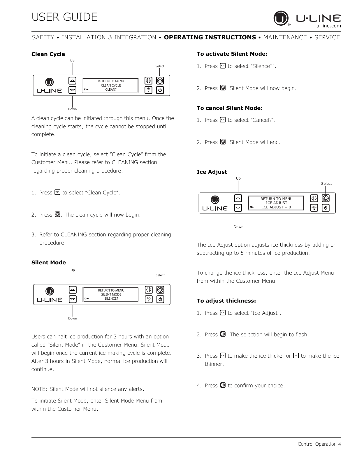
Clean Cycle
A clean cycle can be initiated through this menu. Once the
cleaning cycle starts, the cycle cannot be stopped until
complete.
To initiate a clean cycle, select “Clean Cycle” from the
Customer Menu. Please refer to CLEANING section
regarding proper cleaning procedure.
1. Press to select “Clean Cycle”.
2. Press . The clean cycle will now begin.
3. Refer to CLEANING section regarding proper cleaning
procedure.
Silent Mode
Users can halt ice production for 3 hours with an option
called “Silent Mode” in the Customer Menu. Silent Mode
will begin once the current ice making cycle is complete.
After 3 hours in Silent Mode, normal ice production will
continue.
NOTE: Silent Mode will not silence any alerts.
To initiate Silent Mode, enter Silent Mode Menu from
within the Customer Menu.
To activate Silent Mode:
1. Press to select “Silence?”.
2. Press . Silent Mode will now begin.
To cancel Silent Mode:
1. Press to select “Cancel?”.
2. Press . Silent Mode will end.
Ice Adjust
The Ice Adjust option adjusts ice thickness by adding or
subtracting up to 5 minutes of ice production.
To change the ice thickness, enter the Ice Adjust Menu
from within the Customer Menu.
To adjust thickness:
1. Press to select “Ice Adjust”.
2. Press . The selection will begin to flash.
3. Press to make the ice thicker or to make the ice
thinner.
4. Press to confirm your choice.
Up
Select
Down
RETURN TO MENU
CLEAN CYCLE
CLEAN?
Up
Select
Down
RETURN TO MENU
SILENT MODE
SILENCE?
Up
Select
Down
RETURN TO MENU
ICE ADJUST
ICE ADJUST = 0
33
USER GUIDE
Control Operation 5
u-line.com
SAFETY • INSTALLATION & INTEGRATION • OPERATING INSTRUCTIONS • MAINTENANCE • SERVICE
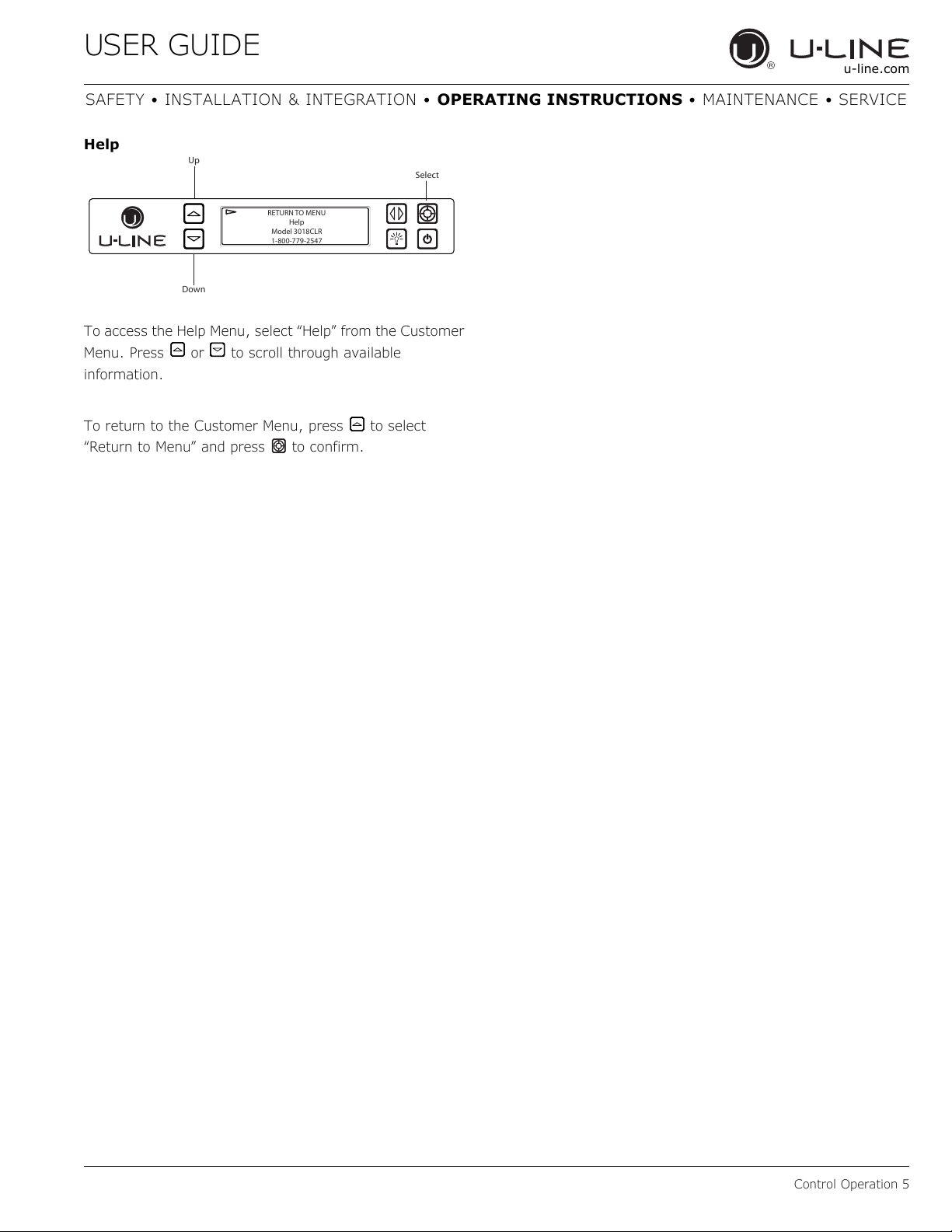
Help
To access the Help Menu, select “Help” from the Customer
Menu. Press or to scroll through available
information.
To return to the Customer Menu, press to select
“Return to Menu” and press to confirm.
Up
Select
Down
RETURN TO MENU
Help
Model 3018CLR
1-800-779-2547
34
USER GUIDE
Ice 1
u-line.com
SAFETY • INSTALLATION & INTEGRATION • OPERATING INSTRUCTIONS • MAINTENANCE • SERVICE
Ice
ICE CUBE THICKNESS ADJUSTMENT
NOTICE
Ice thickness adjustment should only be made
one increment at a time. Allow ice maker
production to stabilize for 24 hours before
rechecking ice thickness.
Ice is produced in layers resulting in a clear cube. Ice in
bin may develop surface frost which disappears when cube
is placed in liquid.
Ice cubes in any given batch will vary, so it is necessary
to choose cubes from the sample area for comparison
when making adjustments.
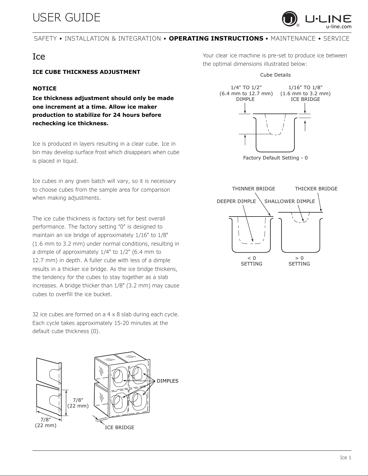
The ice cube thickness is factory set for best overall
performance. The factory setting “0” is designed to
maintain an ice bridge of approximately 1/16" to 1/8"
(1.6 mm to 3.2 mm) under normal conditions, resulting in
a dimple of approximately 1/4" to 1/2" (6.4 mm to
12.7 mm) in depth. A fuller cube with less of a dimple
results in a thicker ice bridge. As the ice bridge thickens,
the tendency for the cubes to stay together as a slab
increases. A bridge thicker than 1/8" (3.2 mm) may cause
cubes to overfill the ice bucket.
32 ice cubes are formed on a 4 x 8 slab during each cycle.
Each cycle takes approximately 15-20 minutes at the
default cube thickness (0).
Your clear ice machine is pre-set to produce ice between
the optimal dimensions illustrated below:
DIMPLES
ICE BRIDGE
7/8"
(22 mm)
7/8"
(22 mm)
1/4" TO 1/2"
(6.4 mm to 12.7 mm)
DIMPLE
1/16" TO 1/8"
(1.6 mm to 3.2 mm)
ICE BRIDGE
Cube Details
Factory Default Setting - 0
THINNER BRIDGE THICKER BRIDGE
DEEPER DIMPLE SHALLOWER DIMPLE
< 0
SETTING
> 0
SETTING
35
USER GUIDE
Ice 2
u-line.com
SAFETY • INSTALLATION & INTEGRATION • OPERATING INSTRUCTIONS • MAINTENANCE • SERVICE
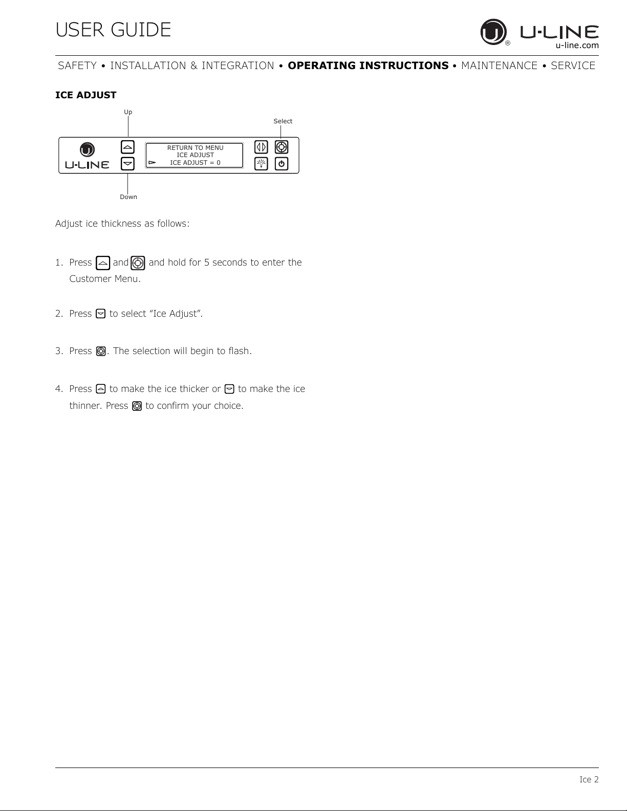
ICE ADJUST
Adjust ice thickness as follows:
1. Press and hold for 5 seconds to enter the
Customer Menu.
2. Press
to select “Ice Adjust”.
3. Press . The selection will begin to flash.
4. Press to make the ice thicker or to make the ice
thinner.
Press to confirm your choice.
Up
Select
Down
RETURN TO MENU
ICE ADJUST
ICE ADJUST = 0
and
36
USER GUIDE
Airflow and Product Loading 1
u-line.com
SAFETY • INSTALLATION & INTEGRATION • OPERATING INSTRUCTIONS • MAINTENANCE • SERVICE
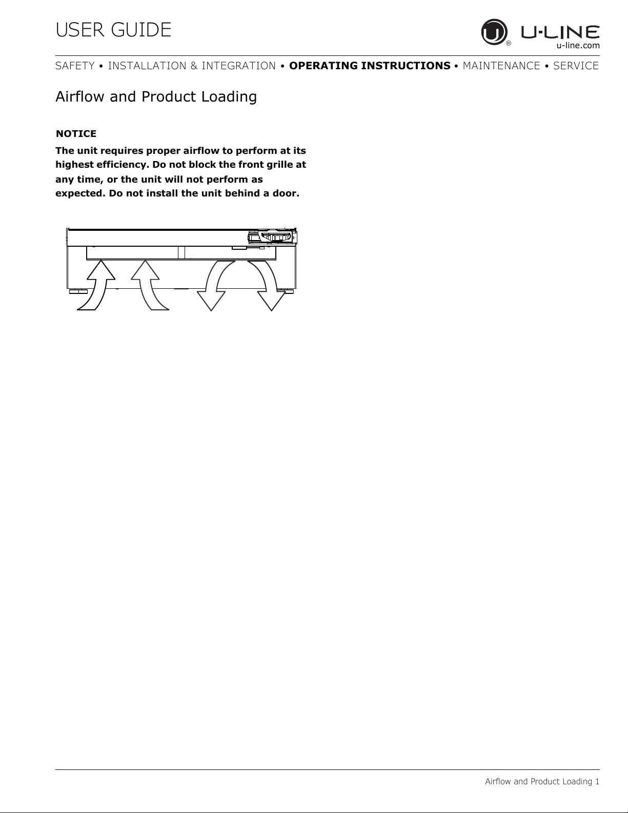
Airflow and Product Loading
NOTICE
The unit requires proper airflow to perform at its
highest efficiency. Do not block the front grille at
any time, or the unit will not perform as
expected. Do not install the unit behind a door.
37
USER GUIDE
Cleaning 1
u-line.com
SAFETY • INSTALLATION & INTEGRATION • OPERATING INSTRUCTIONS • MAINTENANCE • SERVICE
Cleaning
EXTERIOR CLEANING
Stainless Models
Stainless door panels and handles can discolor when
exposed to chlorine gas, pool chemicals, saltwater or
cleaners with bleach.
Keep your stainless unit looking new by cleaning with a
good quality all-in-one stainless steel cleaner and polish
monthly. For best results use Claire
®
Stainless Steel
Polish and Cleaner. Comparable products are acceptable.
Frequent cleaning will remove surface contamination that
could lead to rust. Some installations may require cleaning
weekly.
Do not clean with steel wool pads.
Do not use stainless steel cleaners or polishes on
any glass surfaces.
Clean any glass surfaces with a non-chlorine glass
cleaner.
Do not use cleaners not specifically intended for
stainless steel on stainless surfaces (this
includes glass, tile and counter cleaners).
If any surface discoloring or rusting appears, clean it
quickly with Bon-Ami
®
or Barkeepers Friend Cleanser
®
and
a nonabrasive cloth. Always clean with the grain. Always
finish with Claire
®
Stainless Steel Polish and Cleaner or
comparable product to prevent further problems.
Using abrasive pads such as ScotchBrite™ will
cause the graining in the stainless steel to
become blurred.
Rust not cleaned up promptly can penetrate the
surface of the stainless steel and complete
removal of the rust may not be possible.
Integrated Models
To clean integrated panels, use household cleaner per the
cabinet manufacturer’s recommendations.
INTERIOR CLEANING
Disconnect electric current to the unit.
Clean the interior and all removed components using a
mild nonabrasive detergent and warm water solution
applied with a soft sponge or non-abrasive cloth.
Rinse the interior using a soft sponge and clean water.
Do not use any solvent-based or abrasive
cleaners. These types of cleaners may transfer taste to
the interior products and damage or discolor the lining.
CLEAR ICE MAKER CLEANING CYCLE
The 3000 series ice maker is equipped with an automatic
clean alert function. Cleaning cycles should be run as
notified. Otherwise, to maintain operational efficiency, the
unit should be cleaned every three months. Depending on
water conditions, more frequent cleaning may be
necessary. If the ice maker requires more frequent
cleaning, consult a plumber to test the water quality and
recommend appropriate treatment.
CAUTION
!
Wear rubber gloves and safety goggles and/or
face shield when handling Ice Machine Cleaner.
NOTICE
Discard all ice produced in the first harvest.
Should electricity to the unit be interrupted
during the self-clean cycle, the complete
cleaning cycle will repeat after electricity is
restored.
38
USER GUIDE
Cleaning 2
u-line.com
SAFETY • INSTALLATION & INTEGRATION • OPERATING INSTRUCTIONS • MAINTENANCE • SERVICE
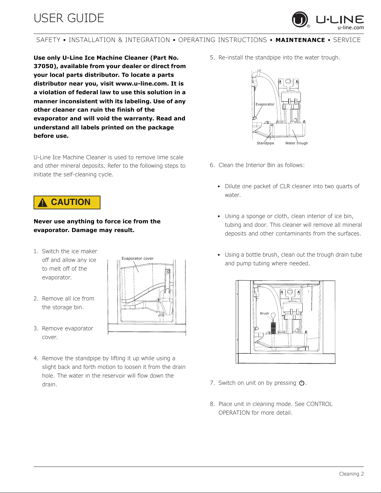
Use only U-Line Ice Machine Cleaner (Part No.
37050), available from your dealer or direct from
your local parts distributor. To locate a parts
distributor near you, visit www.u-line.com. It is
a violation of federal law to use this solution in a
manner inconsistent with its labeling. Use of any
other cleaner can ruin the finish of the
evaporator and will void the warranty. Read and
understand all labels printed on the package
before use.
U-Line Ice Machine Cleaner is used to remove lime scale
and other mineral deposits. Refer to the following steps to
initiate the self-cleaning cycle.
CAUTION
!
Never use anything to force ice from the
evaporator. Damage may result.
1. Switch the ice maker
off and allow any ice
to melt off of the
evaporator.
2. Remove all ice from
the storage bin.
3. Remove evaporator
cover.
4. Remove the standpipe by lifting it up while using a
slight back and forth motion to loosen it from the drain
hole. The water in the reservoir will flow down the
drain.
5. Re-install the standpipe into the water trough.
6. Clean the Interior Bin as follows:
• Dilute one packet of CLR cleaner into two quarts of
water.
• Using a sponge or cloth, clean interior of ice bin,
tubing and door. This cleaner will remove all mineral
deposits and other contaminants from the surfaces.
• Using a bottle brush, clean out the trough drain tube
and pump tubing where needed.
7. Switch on unit on by pressing .
8. Place unit in cleaning mode. See CONTROL
OPERATION for more detail.
Evaporator cover
Standpipe
Evaporator
Water trough
Brush
39
USER GUIDE
Cleaning 3
u-line.com
SAFETY • INSTALLATION & INTEGRATION • OPERATING INSTRUCTIONS • MAINTENANCE • SERVICE
9. When water begins flowing over the evaporator
(approximately 3 minutes), pour 1 packet of CLR
cleaner into the water trough. The cleaning process will
last approximately 45 minutes.
10.Dilute 1 tablespoon (15 ml) bleach in 1 gallon
(3.8 liters) of warm water. Apply this solution to the
entire inside of the storage area. Then rinse thoroughly
with water.
The unit will resume operation approximately 15 minutes
after the automated cleaning process is completed. The
water fill valve will energize, fill the water reservoir, and
shut-off after three minutes. The compressor begins to
operate and water flows over the evaporator assembly (ice
mold). Initially, the water flow may not be uniform,
causing uneven sized cubes or water to spill into the ice
storage bin. This is a normal situation that will correct
itself within the first 24 hours of operation.
NOTICE
Discard all ice produced in the first harvest.
Should power to the unit be interrupted during
the self-clean cycle, the complete cleaning cycle
will repeat after power is restored.
REFRESH KIT
Due to variations in water quality or inadequate
maintenance your unit may become excessively coated in
lime scale or calcium. U-Line offers a cost effective
refresh kit which replaces many interior components and
will return your unit to like new condition. Refresh kits
may be ordered from your local distributor and installed
by your local service company. For information on your
local distributor or service company please visit
www.u-line.com.
40
USER GUIDE
Cleaning Condenser 1
u-line.com
SAFETY • INSTALLATION & INTEGRATION • OPERATING INSTRUCTIONS • MAINTENANCE • SERVICE
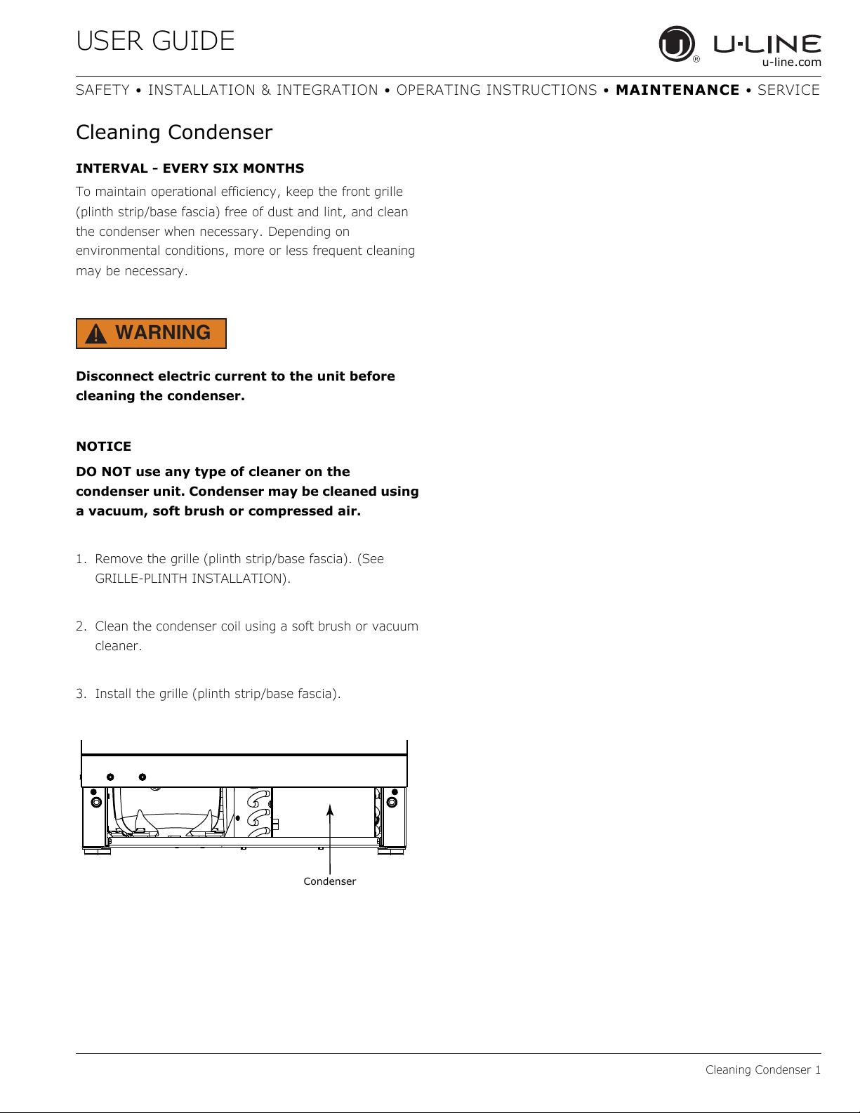
Cleaning Condenser
INTERVAL - EVERY SIX MONTHS
To maintain operational efficiency, keep the front grille
(plinth strip/base fascia) free of dust and lint, and clean
the condenser when necessary. Depending on
environmental conditions, more or less frequent cleaning
may be necessary.
WARNING
!
Disconnect electric current to the unit before
cleaning the condenser.
NOTICE
DO NOT use any type of cleaner on the
condenser unit. Condenser may be cleaned using
a vacuum, soft brush or compressed air.
1. Remove the grille (plinth strip/base fascia). (See
GRILLE-PLINTH INSTALLATION).
2. Clean the condenser coil using a soft brush or vacuum
cleaner.
3. Install the grille (plinth strip/base fascia).
Condenser
41
USER GUIDE
Extended Non-Use 1
u-line.com
SAFETY • INSTALLATION & INTEGRATION • OPERATING INSTRUCTIONS • MAINTENANCE • SERVICE
Extended Non-Use
VACATION/HOLIDAY, PROLONGED SHUTDOWN
The following steps are recommended for periods of
extended non-use:
1. Remove all consumable content from the unit.
2. Disconnect the power cord from its outlet/socket and
leave it disconnected until the unit is returned to
service.
3. Turn off the water supply.
4. If ice is on the evaporator, allow ice to thaw naturally.
5. Clean and dry the interior of the cabinet. Ensure all
water has been removed from the unit.
6. Disconnect the water and drain line (if applicable)
making sure all water is removed from the lines.
7. The door must remain open to prevent formation of
mold and mildew. Open door a minimum of 2"
(50 mm) to provide the necessary ventilation.
WINTERIZATION
If the unit will be exposed to temperatures of 40°F (5°C)
or less, the steps above must be followed. In addition, P60
drain pumps in clear ice machines must be drained
according to the following procedure:
1. Remove the drain pump from the ice machine.
2. Drain the water in the pump’s reservoir by turning the
pump upside down and allowing the water to drain
through the pump’s inlet and vent tube fittings.
3. After water is drained, reinstall the drain pump and
reattach all connections.
For questions regarding winterization, please
call U-Line at 414.354.0300.
CAUTION
!
Damage caused by freezing temperatures is not
covered by the warranty.
Do not put anti-freeze in your unit.
42
Copyright © 2020 U-Line Corporation. All Rights Reserved. | Publication Number 30379 | 11/2020 Rev. O
U-Line Corporation (U-Line) Limited Warranty
One Year Limited Warranty
For one year from the date of original purchase, this warranty covers all parts and labor to repair or replace any part of the product that
proves to be defective in materials or workmanship. For products installed and used for normal residential use, material cosmetic defects
are included in this warranty, with coverage limited to 60 days from the date of original purchase. All service provided by U-Line under the
above warranty must be performed by a U-Line factory authorized servicer, unless otherwise specified by U-Line. Service provided during
normal business hours.
Two Year Limited Warranty (5 Class Product)
For two years from the date of original purchase, this warranty covers all parts and labor to repair or replace any part of the product that
proves to be defective in materials or workmanship. For products installed and used for normal residential use, material cosmetic defects
are included in this warranty, with coverage limited to 60 days from the date of original purchase. All service provided by U-Line under the
above warranty must be performed by a U-Line factory authorized servicer, unless otherwise specified by U-Line. Service provided during
normal business hours.
Available Second & Third Year Limited Warranty
In addition to the standard one and two year warranties outlined above, U-Line offers a one year extension of the warranties from the date
of purchase, free of charge. To take advantage of this extension, you must register your product with U-Line within 60 days from the date
of purchase at u-line.com and provide proof of purchase.
Five Year Sealed System Limited Warranty
For five years from the date of original purchase, U-Line will repair or replace the following parts, labor not included, that prove to be
defective in materials or workmanship: compressor, condenser, evaporator, drier, and all connecting tubing. All service provided by U-Line
under the above warranty must be performed by a U-Line factory authorized servicer, unless otherwise specified by U-Line. Service
provided during normal business hours.
Terms
These warranties apply only to products installed in any one of the fifty states of the United States, the District of Columbia, or the ten
provinces of Canada. The warranties do not cover any parts or labor to correct any defect caused by negligence, accident or improper use,
maintenance, installation, service, repair, acts of God, fire, flood or other natural disasters. The product must be installed, operated, and
maintained in accordance with your product’s User Guide.
The remedies described above for each warranty are the only ones that U-Line will provide, either under these warranties or under any
warranty arising by operation of law. U-Line will not be responsible for any consequential or incidental damages arising from the breach of
these warranties or any other warranty, whether express, implied, or statutory. Some states do not allow the exclusion or limitation of
incidental or consequential damages, so the above limitation or exclusion may not apply to you. These warranties give you specific legal
rights, and you may also have other rights which vary from state to state.
Any warranty that may be implied in connection with your purchase or use of the product, including any warranty of merchantability or any
warranty fit for a particular purpose is limited to the duration of these warranties, and only extends to five years in duration for the parts
described in the section related to the five year limited warranty above. Some states do not allow limitations on how long an implied warranty
lasts, so the above limitations may not apply to you.
• The warranties only apply to the original purchaser and are non-transferable.
• The second, third, and five year warranties cover products installed and used for normal residential or designated marine use only.
• The warranties apply to units operated outside only if designed for outdoor use by model and serial number.
• U-Line Commercial products are covered by the one year and 5 year limited warranties and are not eligible for the second and
third year limited warranties.
• Replacement water filters, light bulbs, and other consumable parts are not covered by these warranties.
• The start of U-Line’s obligation is limited to four years after the shipment date from U-Line.
• In-home instruction on how to use your product is not covered by these warranties.
• Food, beverage, and medicine loss are not covered by these warranties.
• If the product is located in an area where U-Line factory authorized service is not available, you may be responsible for a trip
charge or you may be required to bring the product to a U-Line factory authorized service location at your own cost and expense.
• Units purchased after use as floor displays, and/or certified reconditioned units, are covered by the limited one year warranty only
and no coverage is provided for cosmetic defects.
• Signal issues related to Wi-Fi connectivity are not covered by these warranties.
For parts and service assistance, or to find U-Line factory authorized service near you, contact U-Line:
8900 N. 55
th
Street, Milwaukee, WI 53223 • u-line.com • onlineservice@u-line.com • +1.414.354.0300
43