USER GUIDE & SERVICE MANUAL
Model: UMCR114-WC02A
USERGUIDE&SERVICEMANUAL
TableofContents
Clickonanysectionbelowtojumpdirectlythere
Intro
Safety
Safety and Warning
Disposal And Recycling
Installation
Environmental Requirements
Electrical
Cutout & Product Dimensions
Water Hookup
General Installation
Grille Installation
Door Swing
Door Adjust
Maintenance
Door Latch
Cleaning
Cleaning Condenser
Extended Non-Use
Operating Instructions
First Use
Ice
Airflow and Product Loading
Service
Troubleshooting
Wire Diagram
Product Liability
Warranty Claims
Parts
Ordering Replacement Parts
R600a Specifications
System Diagnosis Guide
Compressor Specifications
Troubleshooting Extended
Defrost
Warranty
USER GUIDE
Introduction
WELCOME TO U-LINE
Congratulations on your U-Line purchase! Your product comes from a company with decades of premium modular ice
making, refrigeration, and wine preservation experience. U-Line creates products focused on functionality, style, and
inspired innovations — paying close attention to even the smallest details. Applications include residential, outdoor, ADA
height compliant, marine, and commercial. Product categories include Beverage Centers, Wine Refrigerators, Ice Machines,
Refrigerators,Freezers,andDispensers.Ouradvancedrefrigerationsystems,largeandexiblecapacities,andclean
integrated look are what makes our products Built-In to Stand Out
®
.Since2014,U-LinehasbeenpartoftheMiddlebyfamily
ofbrands.Productsaredesigned,engineered,andassembledinMilwaukee,Wisconsin,USA,andselectproductsareavailable
worldwide.
U-Line — RIGHT PRODUCT. RIGHT PLACE. RIGHT TEMPERATURE.
®
PRODUCT INFORMATION
Looking for additional information on your product? User Guides, Spec Sheets, CAD Drawings, and Product Warranty
informationareavailabledigitallyonu-line.com.
PROPERTY DAMAGE / INJURY CONCERNS
In the unlikely event property damage or personal injury is suspected related to a U-Line product, please take the following
steps:
1. U-LineCustomerCaremustbecontactedimmediatelyat+1.414.354.0300.
2. ServiceorrepairsperformedontheunitwithoutpriorwrittenapprovalfromU-Lineisnotpermitted.Iftheunithasbeen
alteredorrepairedinthe�eldwithoutpriorwrittenapprovalfromU-Line,claimswillnotbeeligible.
GENERAL INQUIRIES
U-Line Corporation
8900N.55thStreet
Milwaukee,Wisconsin53223USA
Monday-Friday8:00amto4:30pmCST
T:+1.414.354.0300
Email: sales@u-line.com
u-line.com
CONNECT WITH US
SERVICE & PARTS ASSISTANCE
Monday-Friday8:00amto4:30pmCST
T:+1.414.354.0300
Service Email: onlineservice@u-line.com
Parts Email: [email protected]
Designed,engineeredandassembledinWI,USA
3
USER GUIDE
Safety and Warning
Safety and Warning
NOTICE
Please read all instructions before installing,
operating, or servicing the appliance.
Use this appliance for its intended purpose only and follow
these general precautions with those listed throughout this
guide:
SAFETY ALERT DEFINITIONS
Throughout this guide are safety items labeled with a
Danger, Warning, or Caution based on the risk type:
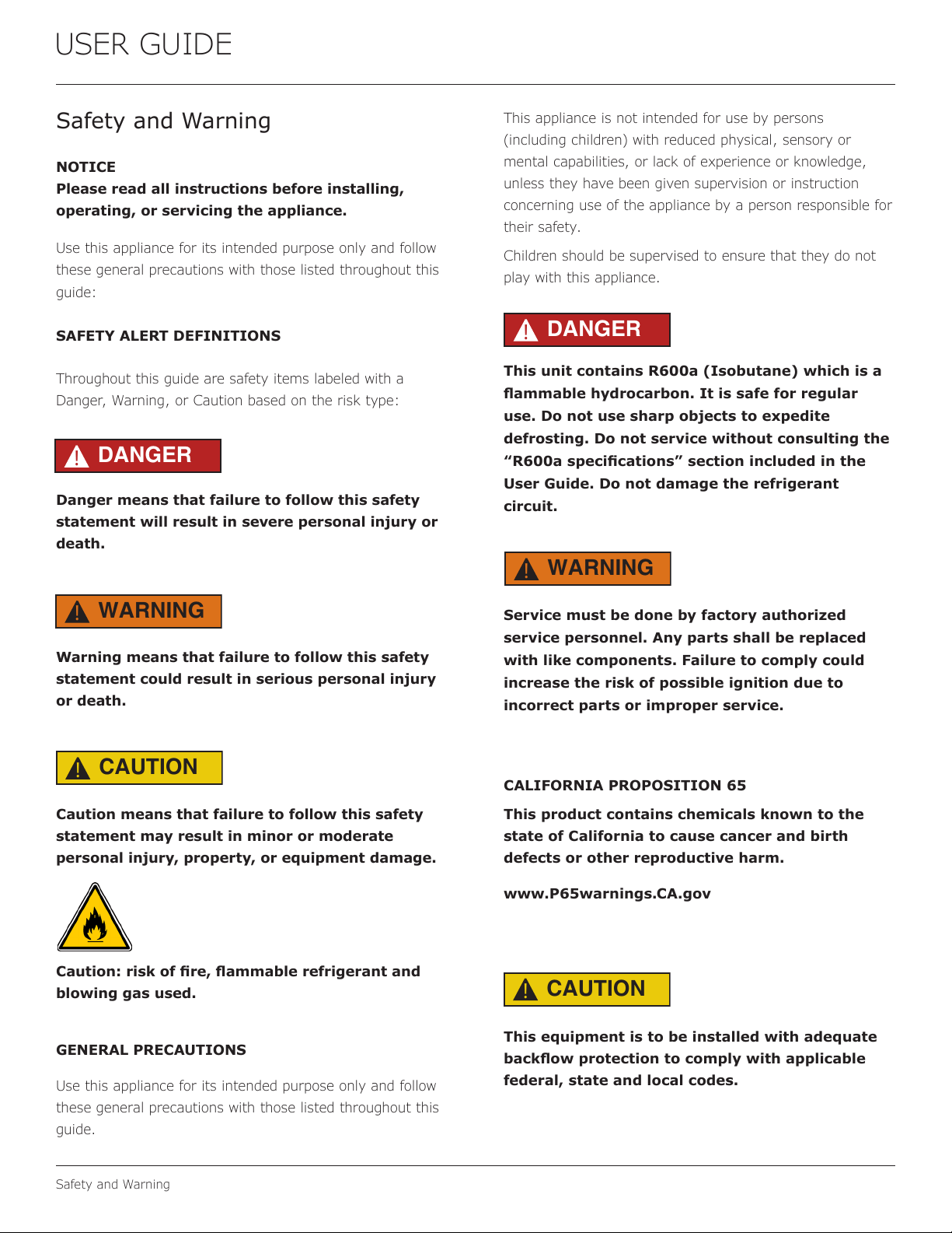
Danger means that failure to follow this safety
statement will result in severe personal injury or
death.
Warning means that failure to follow this safety
statement could result in serious personal injury
or death.
Caution means that failure to follow this safety
statement may result in minor or moderate
personal injury, property, or equipment damage.
Caution:riskofre,ammablerefrigerantand
blowing gas used.
GENERAL PRECAUTIONS
Use this appliance for its intended purpose only and follow
these general precautions with those listed throughout this
guide.
This appliance is not intended for use by persons
(including children) with reduced physical, sensory or
mental capabilities, or lack of experience or knowledge,
unless they have been given supervision or instruction
concerning use of the appliance by a person responsible for
their safety.
Children should be supervised to ensure that they do not
play with this appliance.
This unit contains R600a (Isobutane) which is a
ammablehydrocarbon.Itissafeforregular
use. Do not use sharp objects to expedite
defrosting. Do not service without consulting the
“R600aspecications”sectionincludedinthe
User Guide. Do not damage the refrigerant
circuit.
Service must be done by factory authorized
service personnel. Any parts shall be replaced
with like components. Failure to comply could
increase the risk of possible ignition due to
incorrect parts or improper service.
CALIFORNIA PROPOSITION 65
This product contains chemicals known to the
state of California to cause cancer and birth
defects or other reproductive harm.
www.P65warnings.CA.gov
This equipment is to be installed with adequate
backowprotectiontocomplywithapplicable
federal, state and local codes.
DANGER
!
DANGER
!
WARNING
!
WARNING
!
CAUTION
!
CAUTION
!
4
USER GUIDE
Safety and Warning
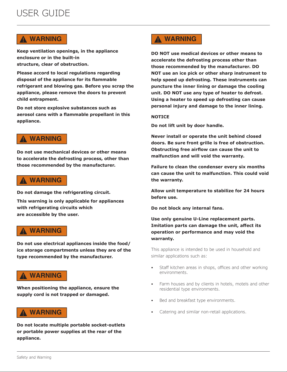
Keep ventilation openings, in the appliance
enclosure or in the built-in
structure, clear of obstruction.
Please accord to local regulations regarding
disposaloftheapplianceforitsammable
refrigerant and blowing gas. Before you scrap the
appliance, please remove the doors to prevent
child entrapment.
Do not store explosive substances such as
aerosolcanswithaammablepropellantinthis
appliance.
Do not use mechanical devices or other means
to accelerate the defrosting process, other than
those recommended by the manufacturer.
Do not damage the refrigerating circuit.
This warning is only applicable for appliances
with refrigerating circuits which
are accessible by the user.
Do not use electrical appliances inside the food/
ice storage compartments unless they are of the
type recommended by the manufacturer.
When positioning the appliance, ensure the
supply cord is not trapped or damaged.
Do not locate multiple portable socket-outlets
or portable power supplies at the rear of the
appliance.
WARNING
!
WARNING
!
WARNING
!
WARNING
!
WARNING
!
WARNING
!
WARNING
!
DO NOT use medical devices or other means to
accelerate the defrosting process other than
those recommended by the manufacturer. DO
NOT use an ice pick or other sharp instrument to
help speed up defrosting. These instruments can
puncture the inner lining or damage the cooling
unit. DO NOT use any type of heater to defrost.
Using a heater to speed up defrosting can cause
personal injury and damage to the inner lining.
NOTICE
Do not lift unit by door handle.
Never install or operate the unit behind closed
doors. Be sure front grille is free of obstruction.
Obstructingfreeairowcancausetheunitto
malfunction and will void the warranty.
Failure to clean the condenser every six months
can cause the unit to malfunction. This could void
the warranty.
Allow unit temperature to stabilize for 24 hours
before use.
Do not block any internal fans.
Use only genuine U-Line replacement parts.
Imitationpartscandamagetheunit,a�ectits
operation or performance and may void the
warranty.
This appliance is intended to be used in household and
similar applications such as:
• Sta�kitchenareasinshops,ocesandotherworking
environments.
• Farm houses and by clients in hotels, motels and other
residential type environments.
• Bed and breakfast type environments.
• Catering and similar non-retail applications.
5

USER GUIDE
Disposal and Recycling
Disposal and Recycling
RISK OF CHILD ENTRAPMENT. Before you throw
awayyouroldrefrigeratororfreezer,takeo�
the doors and leave shelves in place so children
may not easily climb inside.
If the unit is being removed from service for disposal,
check and obey all federal, state, and local regulations
regarding the disposal and recycling of refrigeration
appliances, and follow these steps completely:
1. Remove all consumable contents from the unit.
2. Unplug the electrical cord from its socket.
3. Remove the door(s)/drawer(s).
DANGER
!
6
USERGUIDE
EnvironmentalRequirements
EnvironmentalRequirements
Thismodelisintendedforindoor/interiorapplicationsonly
andisnottobeusedininstallationsthatareopen/
exposedtonaturalelements.
Thisunitisdesignedtooperatebetween50°F(10°C)and
100°F(38°C).Higherambienttemperaturesmayreduce
theunit’sabilitytoreachlowtemperaturesand/orreduce
iceproductiononapplicablemodels.
Forbestperformance,keeptheunitoutofdirectsunlight
andawayfromheatgeneratingequipment.
Inclimateswherehighhumidityanddewpointsare
present,condensationmayappearonoutsidesurfaces.
Thisisconsiderednormal.Thecondensationwill
evaporatewhenthehumiditydrops.
CAUTION
!
Damagescausedbyambienttemperaturesof
40°F(4°C)orbelowarenotcoveredbythe
warranty.
7
USER GUIDE
Electrical
Electrical
SHOCK HAZARD - Electrical Grounding Required.
Never attempt to repair or perform maintenance
on the unit until the electricity has been
disconnected.
Never remove the round grounding prong from
the plug and never use a two-prong grounding
adapter.
Altering, cutting or removing power cord,
removing power plug, or direct wiring can cause
seriousinjury,�re,lossofpropertyand/orlife,
and will void the warranty.
Never use an extension cord to connect power to
the unit.
Always keep your working area dry.
If the detachable type electric supply cord is damaged, it
must be replaced by an equivalent cord available from the
manufacturer or its service agent.
NOTICE
Electrical installation must observe all state and
local codes. This unit requires connection to a
grounded (three-prong), polarized receptacle that
hasbeenplacedbyaquali�edelectrician.
The unit requires a grounded and polarized 220-240 VAC,
50 Hz, 8A power supply (normal household current). An
individual, properly grounded branch circuit or circuit
breaker is recommended. A GFCI (ground fault circuit
interrupter)isusuallynotrequiredfor�xedlocation
appliances and is not recommended for your unit because
it could be prone to nuisance tripping. However, be sure to
consult your local codes.
See CUTOUT & PRODUCT DIMENSIONS for recommended
receptacle location.
WARNING
!
8
USER GUIDE
Cutout & Product Dimensions
Cutout & Product Dimensions
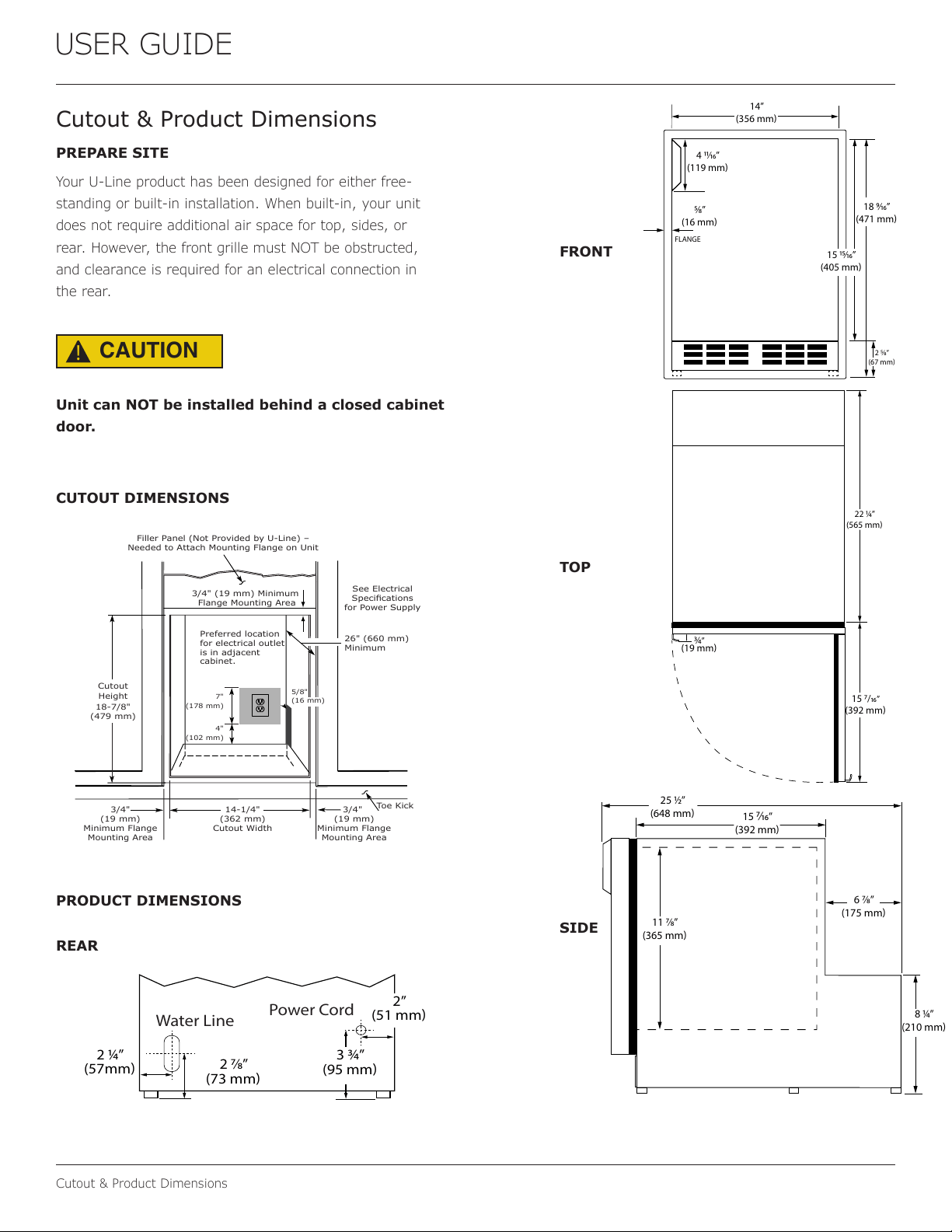
PREPARE SITE
Your U-Line product has been designed for either free-
standing or built-in installation. When built-in, your unit
does not require additional air space for top, sides, or
rear. However, the front grille must NOT be obstructed,
and clearance is required for an electrical connection in
the rear.
CAUTION
!
Unit can NOT be installed behind a closed cabinet
door.
CUTOUT DIMENSIONS
PRODUCT DIMENSIONS
REAR
FRONT
TOP
SIDE
Cutout
Height
18-7/8"
(479 mm)
Filler Panel (Not Provided by U-Line) –
Needed to Attach Mounting Flange on Unit
Toe Kick
14-1/4"
(362 mm)
Cutout Width
3/4"
(19 mm)
Minimum Flange
Mounting Area
3/4" (19 mm) Minimum
Flange Mounting Area
3/4"
(19 mm)
Minimum Flange
Mounting Area
4"
(102 mm)
7"
(178 mm)
Preferred location
for electrical outlet
is in adjacent
cabinet.
5/8"
(16 mm)
26" (660 mm)
Minimum
See Electrical
Specifications
for Power Supply
2 ⁄4”
(57mm)
3 ⁄4”
(95 mm)
2”
(51 mm)
2 ⁄8”
(73 mm)
Water Line
Power Cord
18 ⁄”
(471 mm)
15 ⁄”
(405 mm)
2 ⁄”
(67 mm)
14”
(356 mm)
4 ⁄”
(119 mm)
⁄”
(16 mm)
FLANGE
⁄4
”
(19 mm)
15 7/
”
(392 mm)
22 ⁄4”
(565 mm)
25 ⁄”
(648 mm)
15
⁄
”
(392 mm)
6 ⁄”
(175 mm)
11 ⁄”
(365 mm)
8 ⁄”
(210 mm)
9
USER GUIDE
Water Hookup
Water Hookup
PREPARE PLUMBING
The water valve uses a standard 1/4” (6.35 mm)
compressionfitting.U-Linerecommendsusingaccessory
waterhookupkit–part#ULAWATERHOOKUP.Thekit
includesa10’(3m)braidedflexiblewatersupplylineand
abrasshosefitting.
Plumbing installation must observe all state
and local codes. All water and drain connections
MUSTBEmadebyalicensed/qualiedplumbing
contractor. Failure to follow recommendations
and instructions may result in damage and/or
harm.
WaterSupplyConnection
Whenconnectingthewatersupply,pleasenotethe
following:
• Beforeinstallingtheunitandconnectingtothecold
watersupply,reviewthelocalplumbingcodes.
• The water pressure should be between a minimum of
20andamaximumof120psi(138and827kPa).
• ThewaterlineMUSThaveashut-o�valveinthe
supplyline.
• The water line should be looped into 2 coils. This
willallowtheunittoberemovedforcleaningand
servicing.Makecertainthatthetubingisnotpinched
ordamagedduringinstallation.
Connecttopotablewatersupplyonly.
Donotuseanyplasticwatersupplyline.Theline
isunderpressureatalltimes.Plasticmaycrack
orrupturewithageandcausedamagetoyour
home.
Donotusetapeorjointcompoundwhen
attachingabraidedexiblewatersupplyline
thatincludesarubbergasket.Thegasket
providesanadequateseal–othermaterials
couldcauseblockageofthevalve.
Failure to follow recommendations and
instructions may result in damage and/or harm,
oodingorvoidtheproductwarranty.
Use new hose set. Do not reuse old hose set.
Turno�watersupplyanddisconnectelectrical
supplytounitpriortoinstallation.
Usecautionwhenhandlingbackpanel.Theedges
couldbesharp.
Turno�watersupplyanddisconnectelectricalsupplyto
productpriortoattemptinginstallation.
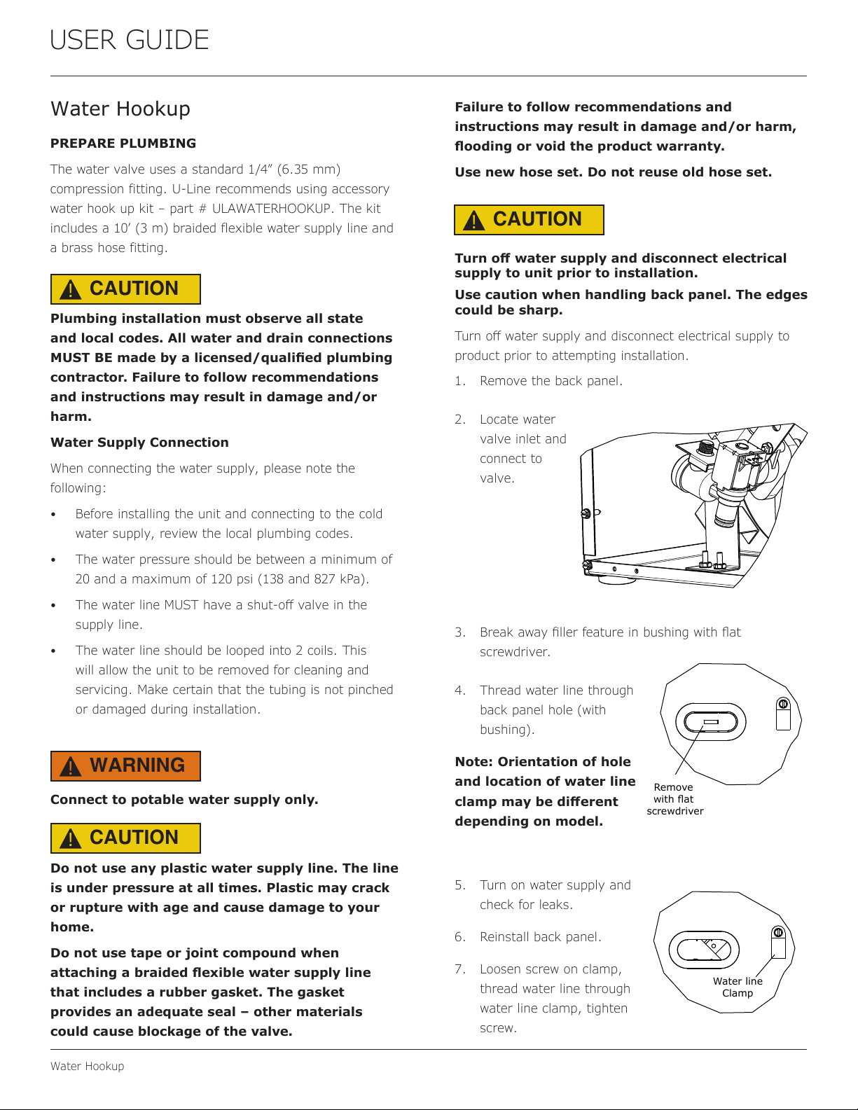
1. Remove the back panel.
2. Locatewater
valve inlet and
connect to
valve.
3. Breakawayllerfeatureinbushingwithat
screwdriver.
4. Threadwaterlinethrough
back panel hole (with
bushing).
Note: Orientation of hole
and location of water line
clampmaybedi�erent
dependingonmodel.
5. Turnonwatersupplyand
check for leaks.
6. Reinstall back panel.
7. Loosenscrewonclamp,
threadwaterlinethrough
waterlineclamp,tighten
screw.
CAUTION
!
CAUTION
!
CAUTION
!
WARNING
!
Remove
withflat
screwdriver
Water line
Clamp
10
USER GUIDE
General Installation
General Installation
LEVELING INFORMATION
NOTICE
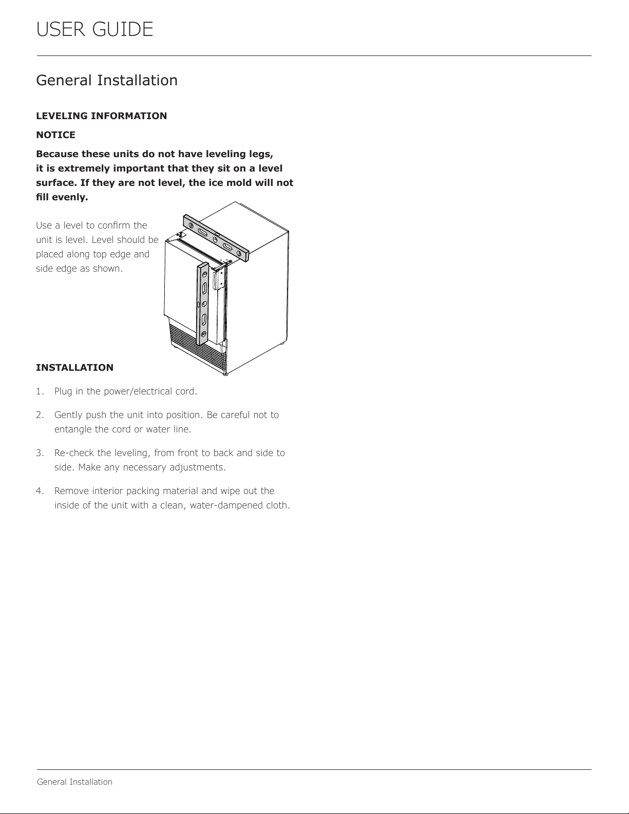
Because these units do not have leveling legs,
it is extremely important that they sit on a level
surface. If they are not level, the ice mold will not
�llevenly.
Usealeveltocon�rmthe
unitislevel.Levelshouldbe
placedalongtopedgeand
sideedgeasshown.
INSTALLATION
1. Pluginthepower/electricalcord.
2. Gentlypushtheunitintoposition.Becarefulnotto
entanglethecordorwaterline.
3. Re-checktheleveling,fromfronttobackandsideto
side.Makeanynecessaryadjustments.
4. Removeinteriorpackingmaterialandwipeoutthe
insideoftheunitwithaclean,water-dampenedcloth.
11
USER GUIDE
Grille Installation
Grille Installation
REMOVING AND INSTALLING GRILLE
Disconnect electric power to the unit before
removing the grille.
When using the unit, the grille must be installed.
DoNOTtouchthecondenser�ns.Thecondenser
�nsareSHARPandcanbeeasilydamaged.
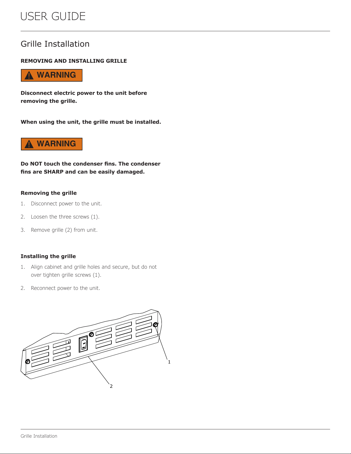
Removing the grille
1. Disconnect power to the unit.
2. Loosen the three screws (1).
3. Remove grille (2) from unit.
Installing the grille
1. Align cabinet and grille holes and secure, but do not
over tighten grille screws (1).
2. Reconnect power to the unit.
WARNING
!
WARNING
!
1
2
12
USER GUIDE
Door Swing
Door Swing
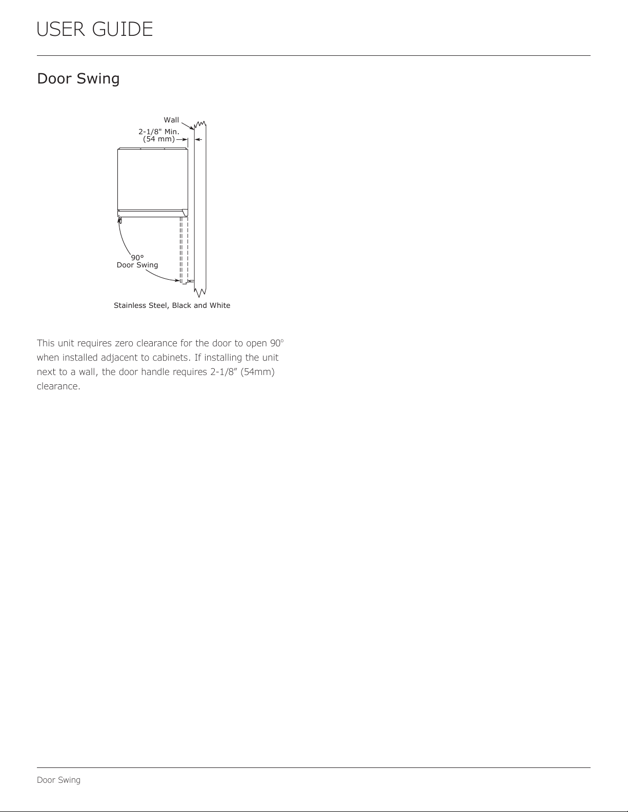
This unit requires zero clearance for the door to open 90
o
when installed adjacent to cabinets. If installing the unit
next to a wall, the door handle requires 2-1/8” (54mm)
clearance.
Wall
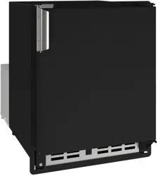
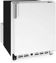
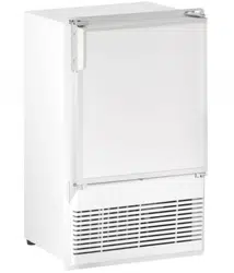
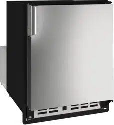
Stainless Steel, Black and White
90°
Door Swing
2-1/8" Min.
(54 mm)
13
USER GUIDE
Door Adjustments
Door Adjustments
DOOR ALIGNMENT AND ADJUSTMENT
Align and adjust the door if it is not level or is not sealing
properly. If the door is not sealed, the unit may not cool
properly, or excessive frost may form in the interior.
NOTICE
Properly aligned, the door’s gasket should be
�rmlyincontactwiththecabinetalltheway
aroundthedoor(nogaps).Carefullyexaminethe
door’sgaskettoensurethatitis�rmlyincontact
withthecabinet.Alsomakesurethedoorgasket
isnotpinchedonthehingesideofthedoor.
To align and adjust the door:
1. Loosen (do not remove) top and bottom hinge screws
using a Torx T-25 screwdriver on the top and a 1/4”
socket on the bottom.
2. Align door squarely with cabinet.
3. Makesuregasketisrmlyincontactwithcabinetall
the way around the door (no gaps).
4. Tighten bottom hinge screws.
5. Tighten top hinge screws.
REVERSING THE DOOR
Location of the unit may make it desirable to mount the
door on the opposite side of the cabinet.
The hinge hardware will be removed and reinstalled on the
opposite side of the cabinet.
Removedoorlatchassembly
Remove door latch assembly and reinstall on opposite side
of door (see DOOR LATCH).
TO REVERSE THE DOOR
Removetophingeanddoor:
1. Hold door to keep it
from falling.
2. Remove top hinge
from cabinet using a
Torx T-25 screwdriver
to remove three
screws.
3. Removedoorbytiltingforwardandliftingdooro�
bottom hinge. Retain shoulder washers; they will be
reused.
4. Remove three screws from hinge holes on the opposite
side.
5. Install three screws into holes where the hinge was
removed.
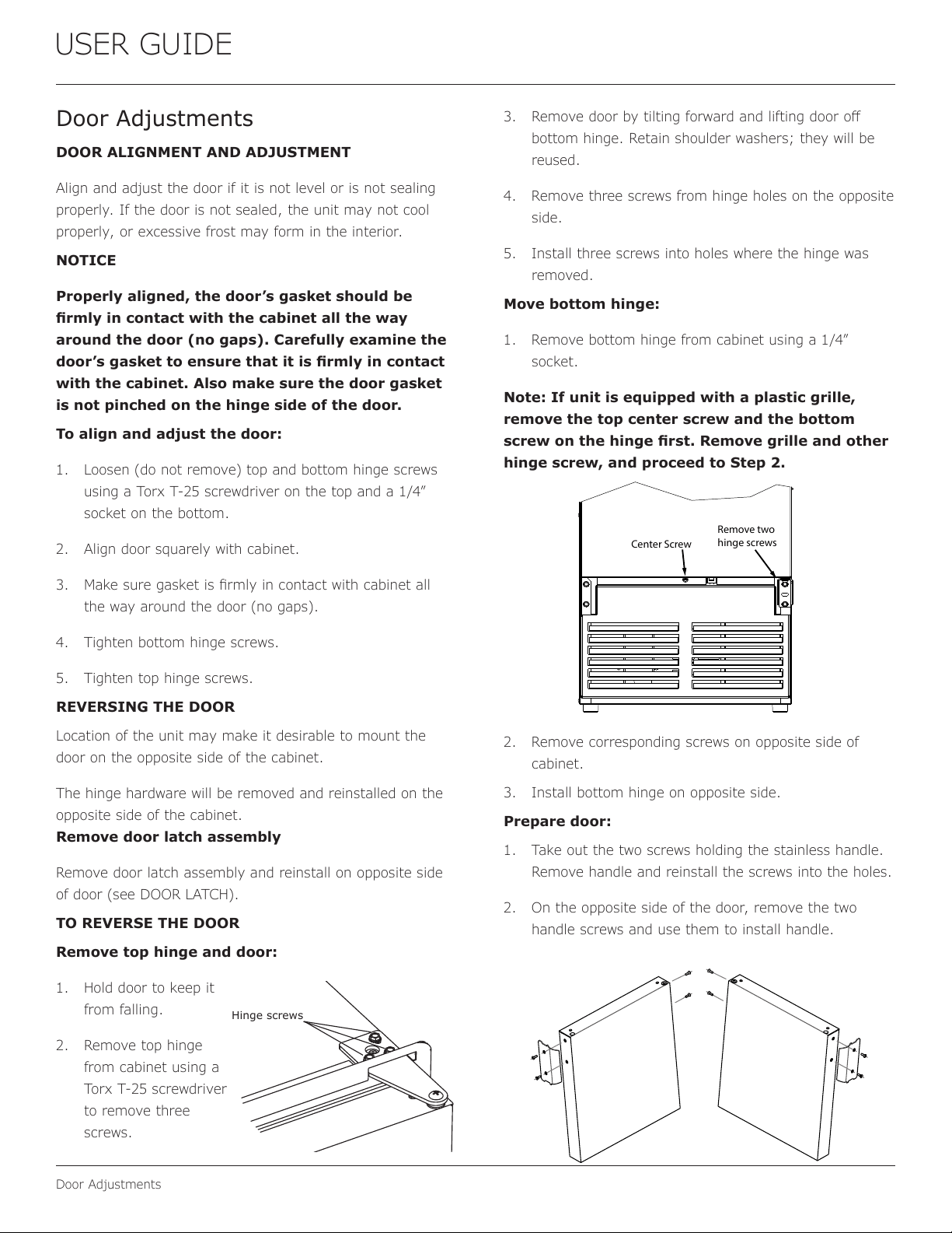
Movebottomhinge:
1. Remove bottom hinge from cabinet using a 1/4”
socket.
Note:Ifunitisequippedwithaplasticgrille,
removethetopcenterscrewandthebottom
screwonthehinge�rst.Removegrilleandother
hingescrew,andproceedtoStep2.
2. Remove corresponding screws on opposite side of
cabinet.
3. Install bottom hinge on opposite side.
Prepare door:
1. Take out the two screws holding the stainless handle.
Remove handle and reinstall the screws into the holes.
2. On the opposite side of the door, remove the two
handle screws and use them to install handle.
Hinge screws
Remove two
hinge screws
Center Screw
14
USER GUIDE
Door Adjustments
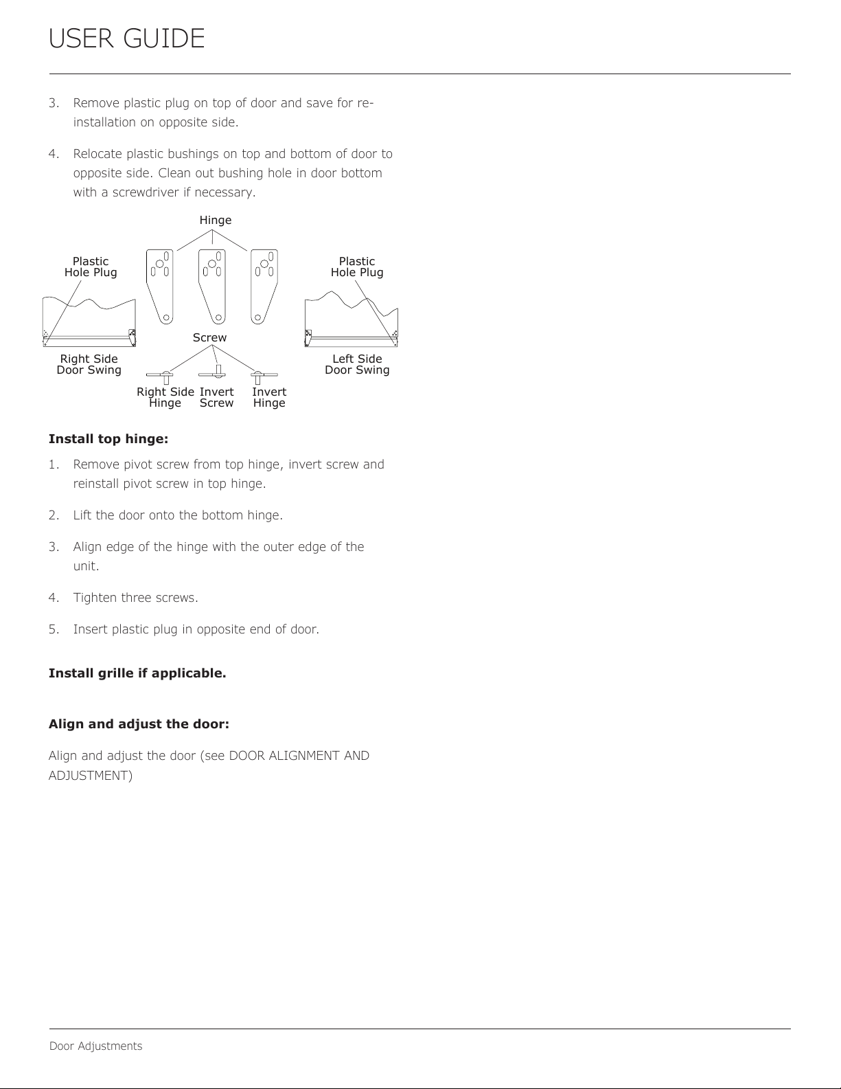
3. Remove plastic plug on top of door and save for re-
installation on opposite side.
4. Relocate plastic bushings on top and bottom of door to
opposite side. Clean out bushing hole in door bottom
with a screwdriver if necessary.
Install top hinge:
1. Remove pivot screw from top hinge, invert screw and
reinstall pivot screw in top hinge.
2. Lift the door onto the bottom hinge.
3. Align edge of the hinge with the outer edge of the
unit.
4. Tighten three screws.
5. Insert plastic plug in opposite end of door.
Installgrilleifapplicable.
Align and adjust the door:
Align and adjust the door (see DOOR ALIGNMENT AND
ADJUSTMENT)
Plastic
Hole Plug
Plastic
Hole Plug
Hinge
Screw
Right Side
Door Swing
Right Side
Hinge
Invert
Screw
Invert
Hinge
Left Side
Door Swing
15
USER GUIDE
Door Latch
Door Latch
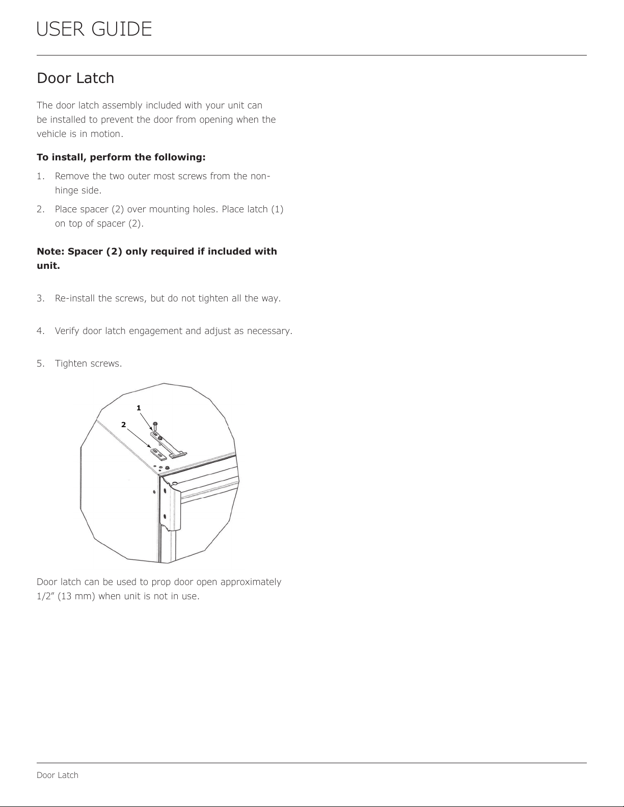
The door latch assembly included with your unit can
be installed to prevent the door from opening when the
vehicle is in motion.
To install, perform the following:
1. Remove the two outer most screws from the non-
hinge side.
2. Place spacer (2) over mounting holes. Place latch (1)
on top of spacer (2).
Note: Spacer (2) only required if included with
unit.
3. Re-install the screws, but do not tighten all the way.
4. Verify door latch engagement and adjust as necessary.
5. Tighten screws.
Door latch can be used to prop door open approximately
1/2” (13 mm) when unit is not in use.
2
1
16
USERGUIDE
FirstUse
FirstUse
Initialstartuprequiresnoadjustments.
NOTICE
U-Linerecommendsdiscardingtheiceproduced
duringthefirsttwotothreehoursofoperation
toavoidpossibledirtorscalethatmaydislodge
fromthewaterline.
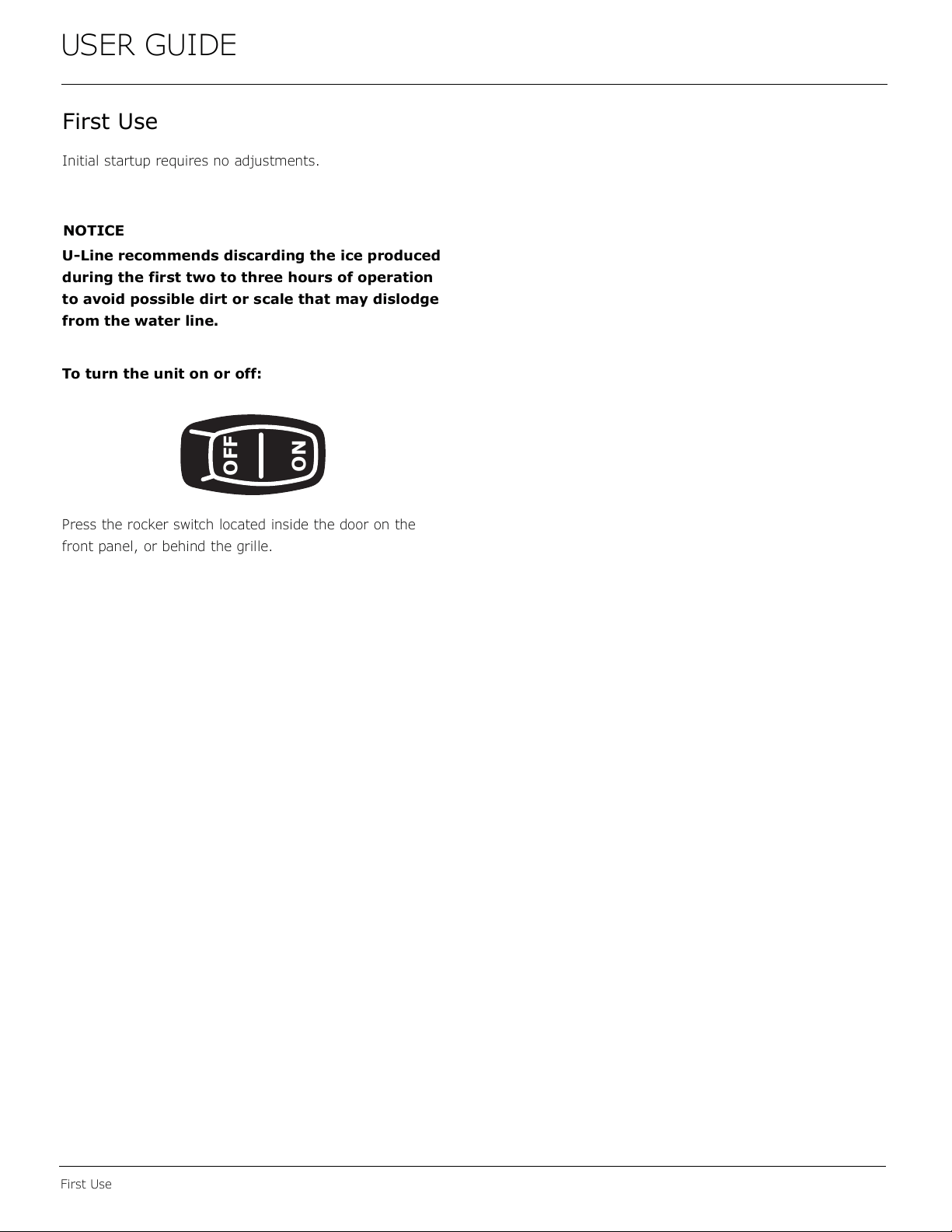
Toturntheunitonoroff:
Presstherockerswitchlocatedinsidethedooronthe
frontpanel,orbehindthegrille.
OFF
ON
17
USERGUIDE
Ice
Ice
ICEMAKEROPERATION
Whentheicebucketisfull,theicemakingmechanismwill
shutoff.However,therefrigerationsystemwillcontinue
tocoolandmaintaintheicesupply.
NOTICE
Donotplacecansorbottlesintheice
compartmentbecausetheywillfreeze.
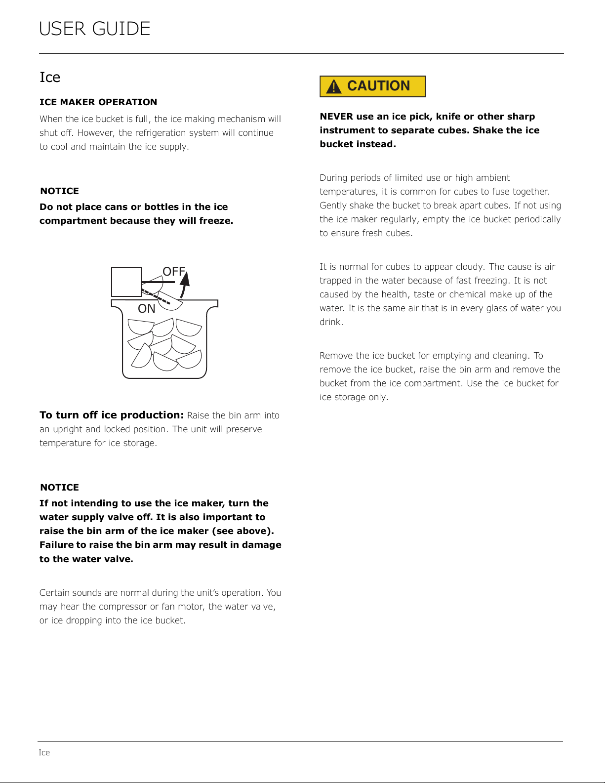
Toturnofficeproduction:
Raisethebinarminto
anuprightandlockedposition.Theunitwillpreserve
temperatureforicestorage.
NOTICE
Ifnotintendingtousetheicemaker,turnthe
watersupplyvalveoff.Itisalsoimportantto
raisethebinarmoftheicemaker(seeabove).
Failuretoraisethebinarmmayresultindamage
tothewatervalve.
Certainsoundsarenormalduringtheunit’soperation.You
mayhearthecompressororfanmotor,thewatervalve,
oricedroppingintotheicebucket.
CAUTION
!
NEVERuseanicepick,knifeorothersharp
instrumenttoseparatecubes.Shaketheice
bucketinstead.
Duringperiodsoflimiteduseorhighambient
temperatures,itiscommonforcubestofusetogether.
Gentlyshakethebuckettobreakapartcubes.Ifnotusing
theicemakerregularly,emptytheicebucketperiodically
toensurefreshcubes.
Itisnormalforcubestoappearcloudy.Thecauseisair
trappedinthewaterbecauseoffastfreezing.Itisnot
causedbythehealth,tasteorchemicalmakeupofthe
water.Itisthesameairthatisineveryglassofwateryou
drink.
Removetheicebucketforemptyingandcleaning.To
removetheicebucket,raisethebinarmandremovethe
bucketfromtheicecompartment.Usetheicebucketfor
icestorageonly.
OFF
ON
18
USERGUIDE
Ice
ICEMAKERADJUSTMENT
IceCubeThicknessAdjustment
Interval-AsRequired
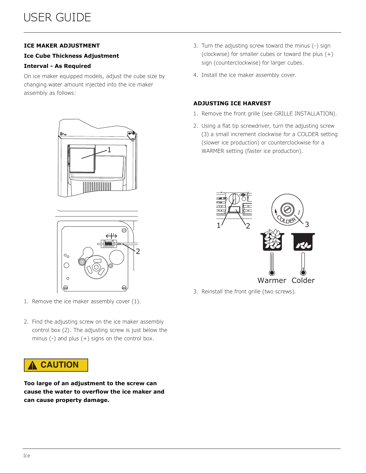
Onicemakerequippedmodels,adjustthecubesizeby
changingwateramountinjectedintotheicemaker
assemblyasfollows:
1. Removetheicemakerassemblycover(1).
2. Findtheadjustingscrewontheicemakerassembly
controlbox(2).Theadjustingscrewisjustbelowthe
minus(-)andplus(+)signsonthecontrolbox.
CAUTION
!
Toolargeofanadjustmenttothescrewcan
causethewatertooverflowtheicemakerand
cancausepropertydamage.
3. Turntheadjustingscrewtowardtheminus(-)sign
(clockwise)forsmallercubesortowardtheplus(+)
sign(counterclockwise)forlargercubes.
4. Installtheicemakerassemblycover.
ADJUSTINGICEHARVEST
1. Removethefrontgrille(seeGRILLEINSTALLATION).
2. Usingaflattipscrewdriver,turntheadjustingscrew
(3) asmallincrementclockwiseforaCOLDERsetting
(slowericeproduction)orcounterclockwisefora
WARMERsetting(fastericeproduction).
3. Reinstallthefrontgrille(twoscrews).
1
2
C
O
L
D
E
R
Warmer Colder
3
1
2
19
USER GUIDE
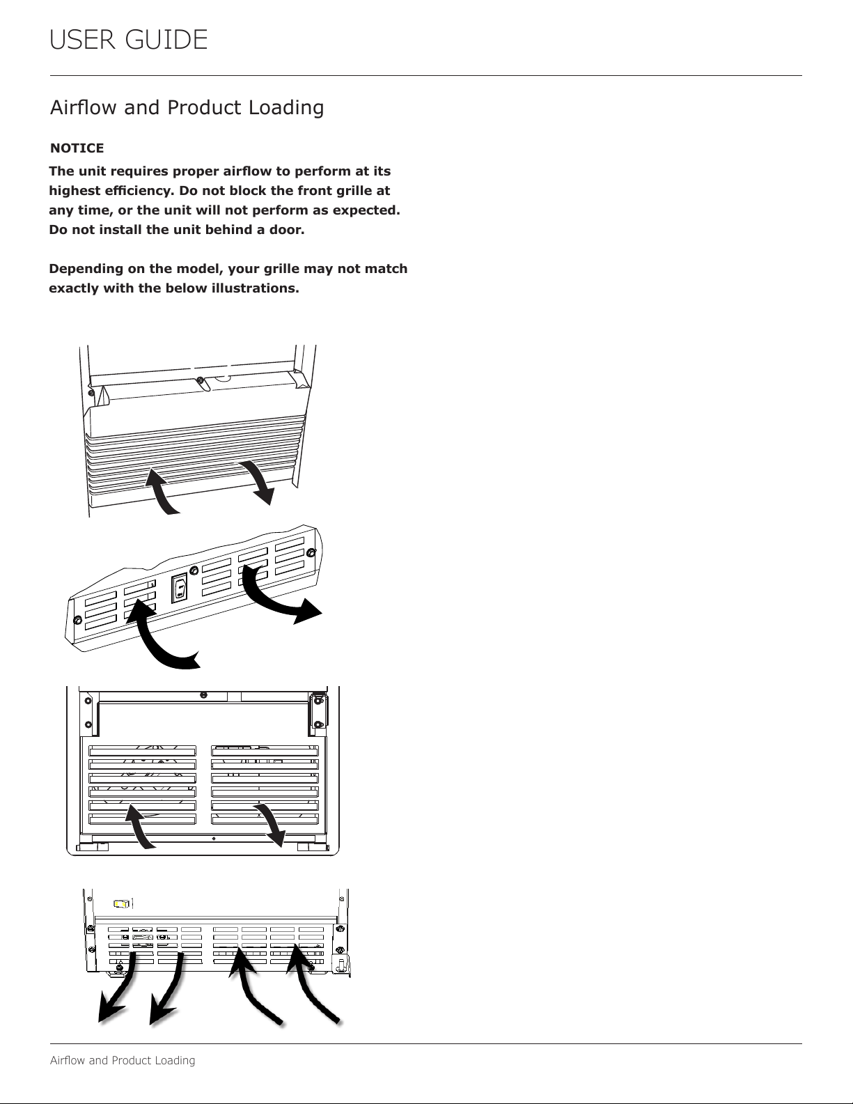
Air�owandProductLoading
Theunitrequiresproperair�owtoperformatits
highesteciency.Donotblockthefrontgrilleat
anytime,ortheunitwillnotperformasexpected.
Donotinstalltheunitbehindadoor.
Dependingonthemodel,yourgrillemaynotmatch
exactlywiththebelowillustrations.
NOTICE
Air�owandProductLoading
20
USERGUIDE
Cleaning
Cleaning
EXTERIORCLEANING
VinylClad(BlackorWhite)Models
Cleansurfaceswithamilddetergentandwarmwater
solution.Donotusesolvent-basedorabrasivecleaners.
Useasoftspongeandrinsewithcleanwater.Wipewitha
soft,cleantoweltopreventwaterspotting.
Cleananyglasssurfaceswithanon-chlorineglass
cleaner.
StainlessModels
Stainlessdoorpanels,handlesandframescandiscolor
whenexposedtochlorinegas,poolchemicals,saltwater
orcleanerswithbleach.
Keepyourstainlessunitlookingnewbycleaningwitha
goodqualityall-in-onestainlesssteelcleanerandpolish
monthly.ForbestresultsuseClaire
®
StainlessSteel
PolishandCleaner.Comparableproductsareacceptable.
Frequentcleaningwillremovesurfacecontaminationthat
couldleadtorust.Someinstallationsmayrequirecleaning
weekly.
Donotcleanwithsteelwoolpads.
Donotusestainlesssteelcleanersorpolisheson
anyglasssurfaces.
Cleananyglasssurfaceswithanon-chlorineglass
cleaner.
Donotusecleanersnotspecificallyintendedfor
stainlesssteelonstainlesssurfaces(this
includesglass,tileandcountercleaners).
Ifanysurfacediscoloringorrustingappears,cleanit
quicklywithBon-Ami
®
orBarkeepersFriendCleanser
®
andanonabrasivecloth.Alwayscleanwiththegrain.
AlwaysfinishwithClaire
®
StainlessSteelPolishand
Cleanerorcomparableproducttopreventfurther
problems.
UsingabrasivepadssuchasScotchBrite™will
causethegraininginthestainlesstobecome
blurred.
Rustnotcleaneduppromptlycanpenetratethe
surfaceofthestainlesssteelandcomplete
removaloftherustmaynotbepossible.
IntegratedModels
Tocleanintegratedpanels,usehouseholdcleanerperthe
cabinetmanufacturer’srecommendations.
INTERIORCLEANING
Disconnectpowertotheunit.
Cleantheinteriorandallremovedcomponentsusinga
mildnonabrasivedetergentandwarmwatersolution
appliedwithasoftspongeornon-abrasivecloth.
Rinsetheinteriorusingasoftspongeandcleanwater.
Donotuseanysolvent-basedorabrasive
cleaners.Thesetypesofcleanersmaytransfertasteto
theinteriorproductsanddamageordiscolortheinterior.
21
USERGUIDE
Cleaning
DEFROSTING
ManualDefrostModels
Thisunitisamanualdefrostmodelandwillrequire
occasionaldefrosting.Whenthereisbuild-upof1/4"
(6 mm)ormoreoffrost,manuallydefrosttheunit.
CAUTION
!
DONOTuseanicepickorothersharp
instrumenttohelpspeedupdefrosting.These
instrumentscanpuncturetheinnerliningor
damagethecoolingunit.DONOTuseanytypeof
heatertodefrost.Usingaheatertospeedup
defrostingcancausepersonalinjuryand
damagetotheinnerlining.
Todefrost:
1. Disconnectpowertotheunit.
2. Removeicebucketanddiscardice.
3. Placetowelorotherabsorbentmaterialonbottomof
icebin.
4. Filltheicebuckethalffullwithwarm,nothotwater.
Thiswillhelptheunitdefrostfaster.
5. Placetheicebucketbackintotheunitontopofthe
towelorotherabsorbentmaterial.
6. Propthedoorinanopenposition(2in.[50mm]
minimum).
7. Afterabout1hourremovetheicebinanddiscard
water.
8. Allowthefrosttomeltnaturally.
9. Afterthefrostmeltscompletelycleantheinteriorand
allremovedcomponents.(SeeINTERIORCLEANING).
NOTICE
DONOTcleanicebucketusingadishwasher.The
bucketisnotdishwashersafeandwillbe
damaged.
10.Whentheinteriorisdry,reconnectpowerandturnunit
on.
NOTE:Tosafeguardagainstcontaminatesinice,discard
firstthreebatchesoficeafterdefrosting.
22
USER GUIDE
Cleaning Condenser
CONDENSER
Cleaning Condenser
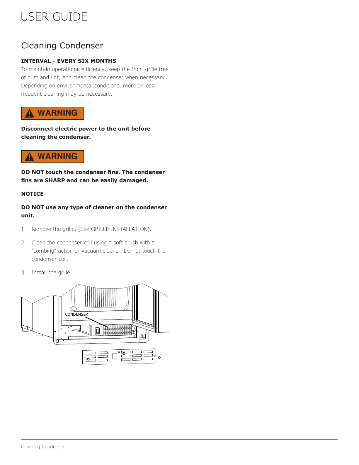
INTERVAL - EVERY SIX MONTHS
Tomaintainoperationale�ciency,keepthefrontgrillefree
ofdustandlint,andcleanthecondenserwhennecessary.
Dependingonenvironmentalconditions,moreorless
frequentcleaningmaybenecessary.
Disconnect electric power to the unit before
cleaning the condenser.
DONOTtouchthecondenser�ns.Thecondenser
�nsareSHARPandcanbeeasilydamaged.
NOTICE
DONOTuseanytypeofcleaneronthecondenser
unit.
1. Removethegrille.(SeeGRILLEINSTALLATION).
2. Cleanthecondensercoilusingasoftbrushwitha
“combing”actionorvacuumcleaner.Donottouchthe
condensercoil.
3. Installthegrille.
WARNING
!
WARNING
!
23
USER GUIDE
Extended Non-Use
Extended Non-Use
VACATION/HOLIDAY, PROLONGED SHUTDOWN
The following steps are recommended for periods of
extended non-use:
1. Remove all consumable content from the unit.
2. Disconnect the power cord from its outlet/socket
and leave it disconnected until the unit is returned to
service.
3. Turno�thewatersupply.
4. Ificeisontheevaporator,allowicetothawnaturally.
5. Cleananddrytheinteriorofthecabinet.Ensureall
water has been removed from the unit.
6. Disconnect the water and drain line (if applicable)
making sure all water is removed from the lines.
7. The door must remain open to prevent formation of
mold and mildew. Open door a minimum of 2” (50
mm) toprovidethenecessaryventilation.
WINTERIZATION
If the unit will be exposed to temperatures of 40°F (5°
C) or less, the steps above must be followed. In
addition, drain pumps in clear ice machines must be
drained according to the following procedure:
1. Remove the drain pump from the ice machine.
2. Drainthewaterinthepump’sreservoirbyturningthe
pump upside down and allowing the water to drain
throughthepump’sinletandventtubettings.
3. After water is drained, reinstall the drain pump and
reattach all connections.
For questions regarding winterization, please call
U-Line at 414.354.0300.
CAUTION
!
Damage caused by freezing temperatures is not
covered by the warranty.
Do not put anti-freeze in your unit.
24
USER GUIDE
Troubleshooting
If you think your U-Line product is malfunctioning, read
the CONTROL OPERATION section to clearly understand
the function of the control.
If the problem persists, read the NORMAL OPERATING
SOUNDS and TROUBLESHOOTING GUIDE sections below
to help you quickly identify common problems and
possible causes and remedies. Most often, this will resolve
the problem without the need to call for service.
If your product needs service, please go to
www.u-line.com/servicers/ and navigate to the Find a
Servicer page to locate a U-Line Authorized servicer. Please
make sure to register it at
www.U-Line.com/u-lineregistration. If you have any
issues following this process you can contact the U-Line
Corporation by phone at +1.414.354.0300; please make
sure you have your product Model and Serial Numbers
handy; They can can be found on the Serial number plate
located within the interior of your product, most often
placed on the ceiling.
All models incorporate rigid foam insulated cabinets to
providehighthermaleciencyandmaximumsound
reduction for its internal working components. Despite this
technology, your model may make sounds that are
unfamiliar.
Normal operating sounds may be more noticeable because
of the unit’s environment. Hard surfaces such as cabinets,
wood,vinylortiledoorsandpaneledwallshavea
tendencytoreectnormalapplianceoperatingnoises.
Listed below are common refrigeration components with a
brief description of the normal operating sounds they
make. NOTE: Your product may not contain all the
components listed.
• Compressor: The compressor makes a hum or pulsing
sound that may be heard when it operates.
BEFORE CALLING FOR SERVICE
TROUBLESHOOTING GUIDE
ELECTROCUTION HAZARD. Never attempt to
repair or perform maintenance on the unit
before disconnecting the main electrical power.
Troubleshooting - What to check when problems occur:
NORMAL OPERATING SOUNDS
Troubleshooting
• Evaporator:Refrigerantowingthroughanevaporator
may sound like boiling liquid.
• Condenser Fan: Air moving through a condenser may
be heard.
• Running Water: As your unit continues to produce
iceyouwillhearwaterowingintothecollection
chambers and running through the evaporator.
DANGER
!
Problem Possible Cause and Remedy
Unit Does Not
Operate.
No electrical supply. Plug unit in or
check
circuit breaker.
Light Remains
on When Door
is Closed
Turno�lightswitchifequipped.
Check reed switch.
Unit Develops
Condensation
onExternal
Surfaces.
Theunitmaybeexposedtoexcessive
humidity.
Moisture will dissipate as humidity
levels decrease.
Poor Ice
Quality.
Ice maker system may be dirty. Clean
the ice maker.
No Ice
Production.
Ensure water is being supplied to the
unit.
Verify the bin arm on the ice making
device is not locked in the up position.
If it is, gently push the bin arm down.
See Ice Maker Production in the ICE
section of this manual.
Not Enough
Ice.
Ensure the condenser coil is clean and
free of any dirt or lint build-up.
Check ICE section of this manual for
more information.
Water in Ice
Bin.
Ensureunitisnotlocatedinexcessive
ambient temperatures or in direct
sunlight.
Ensure the door is closing and sealing
properly.
Ensure nothing is blocking the front
grille, found at the bottom of the unit.
Ensure the condenser coil is clean and
free of any dirt or lint build-up.
25
USER GUIDE
Wire Diagram 1
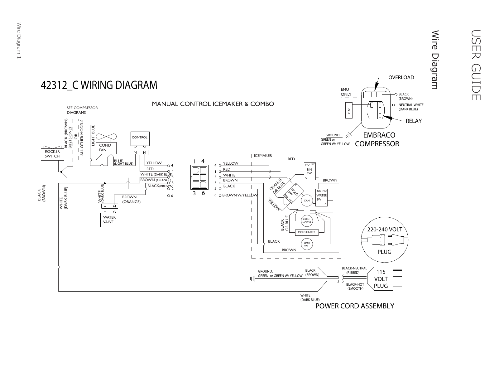
42312_C WIRING DIAGRAM
NEUTRAL WHITE
(DARK BLUE)
BLACK
(BROWN)
RELAY
EMBRACO
COMPRESSOR
GREEN or
GREEN W/ YELLOW
GROUND:
OVERLOAD
CAP
EMU
ONLY
MANUAL CONTROL ICEMAKER & COMBO
ROCKER
SWITCH
COND
FAN
WATER
VALVE
SEE COMPRESSOR
DIAGRAMS
BROWN
(ORANGE)
LIGHT BLUE
BLUE
(LIGHT BLUE)
WHITE
(DARK BLUE)
BLACK (BROWN)
BLACK
(BROWN)
WHITE
(DARK BLUE)
BIN
SW
NO
NC
C
WATER
SW
NC
NO
C
H
O
L
D
S
W
NO
N
C
C
CAM
3 RPM
MOTOR
LIMIT
SW
MOLD HEATER
YELLOW
BLACK
RED
WHITE
WHITE
(DARK BLUE)
BROWN
YELLOW
RED
BROWN
(ORANGE)
BLACK
(BROWN)
BROWN W/YELLOW
RED
YEL
L
OW
BROWN
BLACK
BROWN
OR
ANGE
OR BLUE
BLACK
OR BLUE
OR
ALL OTHER MODELS
ICEMAKER
BI1215 ONLY
CONTROL
POWER CORD ASSEMBLY
GROUND:
GREEN or GREEN W/ YELLOW
115
VOLT
PLUG
220-240 VOLT
PLUG
BLACK-HOT
(SMOOTH)
BLACK-NEUTRAL
(RIBBED)
BLACK
(BROWN)
WHITE
(DARK BLUE)
1
3
6
4
4
1
5
3
2
6
4
1
5
3
2
6
Wire Diagram
26
USER GUIDE
Product Liability
Field service technicians are authorized to make an initial
assessment in the event of reported damages. If there are
any questions about the process involved, the technician
should call U-Line for further explanation.
While inspecting for defects or installation issues, photos
should be taken to document any damages or issues found.
During the assessment, if the service technician is able to
�ndthesourceofthedamageanditcanberesolvedby
replacement of a part, the servicer is authorized to replace
the part in question. The part that caused the damage
must be returned to U-Line in its entirety. The part must
be clearly labeled with the serial number of the unit it was
removed from, the date, and the servicer who removed the
part.
If the service technician determines the damage is the
result of installation issues (water connection/drain, etc.),
theconsumerwouldbenoti�edandtheissuesshallbe
resolved at the direction of the consumer.
If damage is evident and the service technician is
unableto�ndthesource,U-Linemustbecontactedat
+1.414.354.0300 for further direction.
8900 N. 55th Street • Milwaukee, WI 53223
T: +1.414.354.0300 • F: +1.414.354.5696
Website: www.u-line.com
Right product. Right place.
Right temperature Since 1962.
Product Liability
27
USER GUIDE
Warranty Claims
Thefollowinginformationde�nestheparametersfor�linga
warranty claim:
• Validserialnumberneeded
• Validmodelnumberneeded
• Claimsmustbesubmittedonlineat
www.U-LineService.com
• 60daysubmittaldeadlinefromdateofcompleted
service
• Onlyonerepairorunitperwarrantyclaim
• Partordernumberswillberequiredwhensubmitting
forwarrantylabor
Unitsmustberegisteredpriortowarrantysubmittal.
Customersmayregisteratwww.U-Line.com.Aproof
ofpurchaseisrequired.Wealsoacceptthefollowing
informationtoupdatewarranty:
• Newconstructionoccupancydocuments
• Closingpaperwork
• Finalbilling-Remodel
WarrantypartswillbeshippedatnochargeafterU-Line
con�rmswarrantystatus.Pleaseprovidethemodel,serial
number,partnumberandpartdescription.Somepartswill
requirecolororvoltageinformation.
Warranty Claims
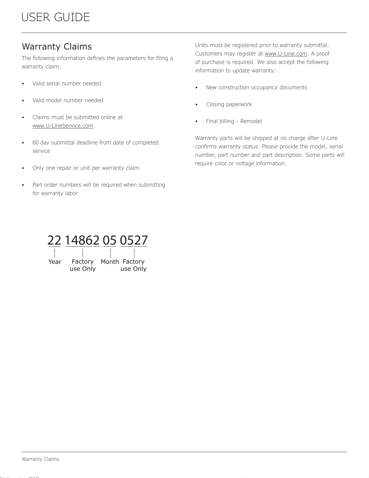
22 14862 05 0527
Year
Factory
use Only
Factory
use Only
Month
28
USER GUIDE
Parts
Parts
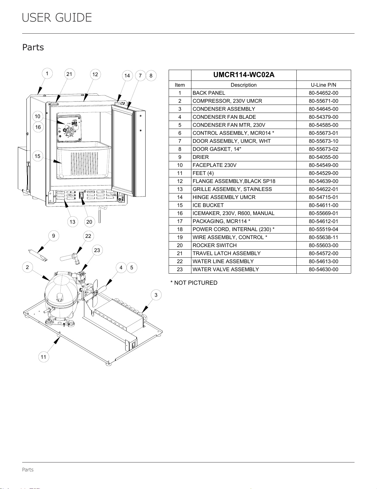
UMCR114-WC02A
Item Description U-Line P/N
1 BACK PANEL 80-54652-00
2 COMPRESSOR, 230V UMCR 80-55671-00
3 CONDENSER ASSEMBLY 80-54645-00
4 CONDENSER FAN BLADE 80-54379-00
5 CONDENSER FAN MTR, 230V 80-54585-00
6 CONTROL ASSEMBLY, MCR014 * 80-55673-01
7 DOOR ASSEMBLY, UMCR, WHT 80-55673-10
8 DOOR GASKET, 14" 80-55673-02
9 DRIER 80-54055-00
10 FACEPLATE 230V 80-54549-00
11 FEET (4) 80-54529-00
12 FLANGE ASSEMBLY,BLACK SP18 80-54639-00
13 GRILLE ASSEMBLY, STAINLESS 80-54622-01
14 HINGE ASSEMBLY UMCR 80-54715-01
15 ICE BUCKET 80-54611-00
16 ICEMAKER, 230V, R600, MANUAL 80-55669-01
17 PACKAGING, MCR114 * 80-54612-01
18 POWER CORD, INTERNAL (230) * 80-55519-04
19 WIRE ASSEMBLY, CONTROL * 80-55638-11
20 ROCKER SWITCH 80-55603-00
21 TRAVEL LATCH ASSEMBLY 80-54572-00
22 WATER LINE ASSEMBLY 80-54613-00
23 WATER VALVE ASSEMBLY 80-54630-00
* NOT PICTURED
14
7 8
12
1
13
15
20
21
10
16
2
3
4 5
9
11
23
22
29
USER GUIDE
Ordering Replacement Parts
Ordering Replacement Parts
Parts may be ordered online at www.U-Line.com
See our contact information below:
www.U-LineService.com (with service login)
Phone Number: +1.414.354.0300
NOTICE
Use only genuine U-Line replacement parts.
The use of non-U-Line parts can reduce speed
oficeproduction,causewatertoover�owfrom
ice maker mold, damage the unit, and void the
warranty.
Warranty parts will be shipped at no charge after U-Line
con�rmswarrantystatus.Pleaseprovidethemodel,serial
number,partnumberandpartdescription.Somepartswill
require color or voltage information.
IfU-Linerequiresthereturnoforiginalparts,wewill
inform you when the parts order is taken. This
requirement will be noted on your packing list. A
prepaid shipping label will be emailed to you. Please
enclose a copy of the parts packing list and be sure the
model and serial numbers are legible on the paperwork.
Tag the part with the reported defect.
Customers and non-authorized servicers may order non-
warranty parts at www.u-line.com. Authorized servicers
with a servicer login may order non-warranty parts at
www.u-lineservice.com.
30
USER GUIDE
R-600ASpeci�cations
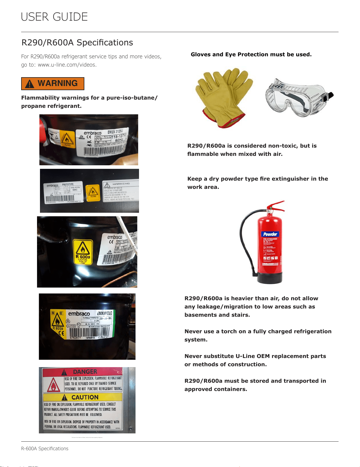
R290/R600ASpeci�cations
For R290/R600a refrigerant service tips and more videos,
go to: www.u-line.com/videos.
Flammability warnings for a pure-iso-butane/
propane refrigerant.
WARNING
!
R290/R600a is considered non-toxic, but is
ammablewhenmixedwithair.
Keepadrypowdertype�reextinguisherinthe
work area.
R290/R600aisheavierthanair,donotallow
anyleakage/migrationtolowareassuchas
basements and stairs.
Neveruseatorchonafullychargedrefrigeration
system.
NeversubstituteU-LineOEMreplacementparts
ormethodsofconstruction.
R290/R600a must be stored and transported in
approvedcontainers.
31
R-600ASpeci�cations
USER GUIDE
Onlyskilledandwelltrainedservicetechnicians
permittedtoserviceR290/R600aequipped
products.
Alltoolsandequipmentmustbeapprovedfor
usewithR290/R600arefrigerant.
Local,stateandfederallaws,standardsmust
beobservedalongwithpropercerti�cationand
licensing.
Ventilationisrequiredduringservicing.
NoconversionstoR290/R600afromanyother
refrigerants.OEMR290/R600aequippedunit
only.
Serviceareamustbefreeofignitionsources.
Nosmokingisallowedintheservicearea.
All replacement electrical components must be
OEMandinstalledproperly(sealedandcovered).
Iftheevaporatoriscoldpriortoservice,itmust
bethawedpriortoservice.
Whenusingavacuumpump,startpumpbefore
opening refrigeration system.
Vacuumpumpandrecoveryequipmentshouldbe
atleast10feetfromtheworkarea.
ItisrecommendedthatasimpleLPGgas
detectorisonsiteduringservice.
EnsurethatallR290/R600aisremovedfromthe
systempriortobrazinganypartofthesealed
system.
Onlyaclean,dry,leak-freesystemshouldbe
chargedwithR290/R600a.
R290/R600aSPECIFICATIONS/LABELING
R290/R600a equipped products are labeled (both the unit
and the compressor).
R290/R600a is colorless and odorless.
R290/R600aisconsiderednon-toxic,butisammable
when mixed with air.
Do not remove or alter any R290/R600a labeling on the
product.
Use only a refrigerant grade R290/R600a from a properly
labeled container.
RECOVERING/RECLAIMINGR290/R600a
(R290/R600a has been exempted from recovery/reclaiming
requirements by the US EPA)
Recovery/Reclaiming equipment must be approved for use
with R290/R600a.
Ensure the evaporator is at room temperature prior to
recovery/reclaiming R290/R600a.
Use a common piercing pliers or piercing valve to remove
R290/R600a from the compressor process tube. (Note:
Piercing devices must not be left on the system and must
be replaced with a Schrader type valve.)
WARNING
!
32
USER GUIDE
R-600ASpeci�cations
Evacuate/reclaim via the piecing pliers to ensure the
system is empty of R290/R600a before any system work is
performed.
The recovery cylinder must be evacuated (no air inside)
prior to accepting R290/R600a.
Therecoverycylindermustnotbe�lledmorethan45%
safe�lllevelandrefrigerantsmustnotbemixed.
The recovery cylinder must be clearly marked with R290/
R600a and Flammable Warning labels.
Ensure proper ventilation during recovery/reclaiming of
R290/R600a.
Start vacuum pump/recovery pump prior to piercing the
compressor process tube.
Followrecovery/reclaimOEMinstructionsforthespeci�c
equipment used.
SYSTEMREPAIR
Ensure no residual R290/R600a refrigerant is left within the
systempriortorepair(simpleventingisnotsucient).
Evacuate and charge with dry nitrogen for leak checks.
Repair leaks or replace system parts as required.
When re-brazing, the system must be purged with
dry nitrogen and at least one access point open to the
atmosphere.
When re-brazing, proper ventilation is required along
with constant monitoring for the presence of R290/R600a
refrigerant.
The�lterdryermustbereplacedanytimethesealed
system is serviced.
No system should be open to the atmosphere for longer
than15minutestoavoidmoisturemigrationintothe
system components.
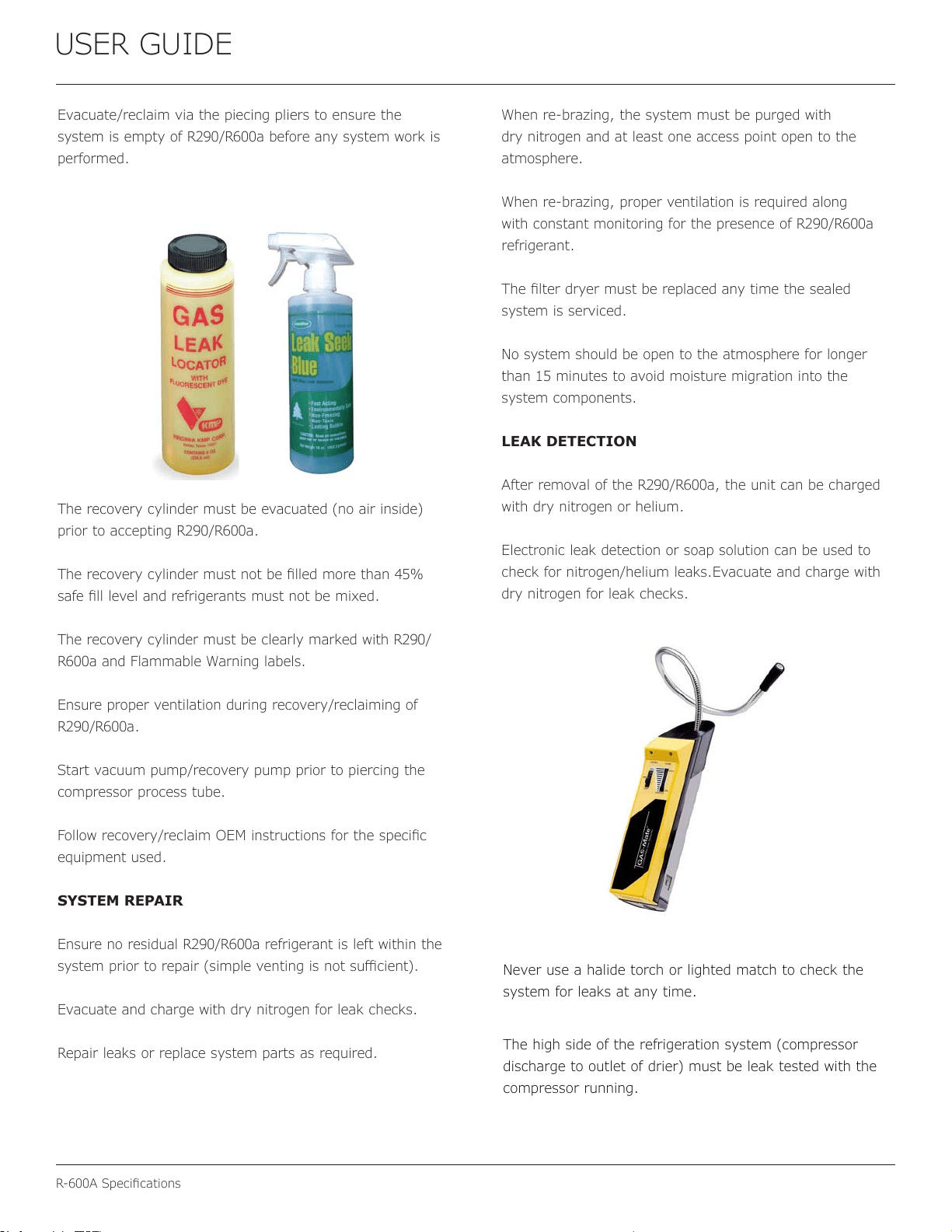
LEAKDETECTION
After removal of the R290/R600a, the unit can be charged
with dry nitrogen or helium.
Electronic leak detection or soap solution can be used to
check for nitrogen/helium leaks.Evacuate and charge with
dry nitrogen for leak checks.
33
R-600ASpeci�cations
USER GUIDE
No air is ever to be allowed inside the refrigeration system
(R290/R600a refrigerant or dry nitrogen only).
Never use a torch on a fully charged refrigeration system.
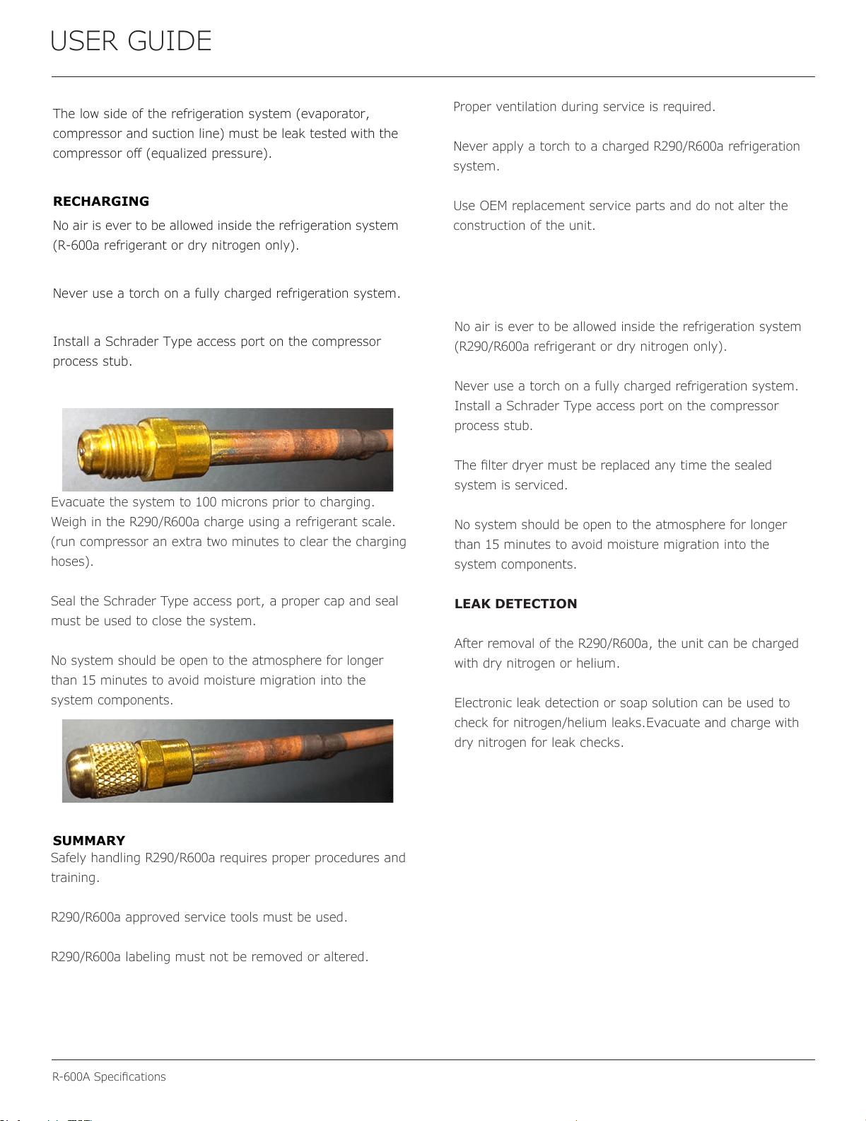
Install a Schrader Type access port on the compressor
process stub.
The�lterdryermustbereplacedanytimethesealed
system is serviced.
No system should be open to the atmosphere for longer
than15minutestoavoidmoisturemigrationintothe
system components.
LEAKDETECTION
After removal of the R290/R600a, the unit can be charged
with dry nitrogen or helium.
Electronic leak detection or soap solution can be used to
check for nitrogen/helium leaks.Evacuate and charge with
dry nitrogen for leak checks.
Evacuate the system to 100 microns prior to charging.
Weigh in the R290/R600a charge using a refrigerant scale.
(run compressor an extra two minutes to clear the charging
hoses).
Seal the Schrader Type access port, a proper cap and seal
must be used to close the system.
No system should be open to the atmosphere for longer
than15minutestoavoidmoisturemigrationintothe
system components.
Safely handling R290/R600a requires proper procedures and
training.
R290/R600a approved service tools must be used.
R290/R600a labeling must not be removed or altered.
Proper ventilation during service is required.
Never apply a torch to a charged R290/R600a refrigeration
system.
Use OEM replacement service parts and do not alter the
construction of the unit.
34
USER GUIDE
System Diagnosis Guide
System Diagnosis Guide
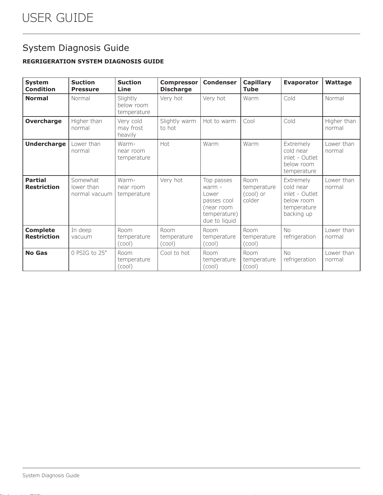
REGRIGERATION SYSTEM DIAGNOSIS GUIDE
System
Condition
Suction
Pressure
Suction
Line
Compressor
Discharge
Condenser Capillary
Tube
Evaporator Wattage
Normal Normal Slightly
below room
temperature
Very hot Very hot Warm Cold Normal
Overcharge Higher than
normal
Very cold
may frost
heavily
Slightly warm
to hot
Hot to warm Cool Cold Higher than
normal
Undercharge Lower than
normal
Warm-
near room
temperature
Hot Warm Warm Extremely
cold near
inlet - Outlet
below room
temperature
Lower than
normal
Partial
Restriction
Somewhat
lower than
normal vacuum
Warm-
near room
temperature
Very hot Top passes
warm -
Lower
passes cool
(near room
temperature)
due to liquid
Room
temperature
(cool) or
colder
Extremely
cold near
inlet - Outlet
below room
temperature
backing up
Lower than
normal
Complete
Restriction
In deep
vacuum
Room
temperature
(cool)
Room
temperature
(cool)
Room
temperature
(cool)
Room
temperature
(cool)
No
refrigeration
Lower than
normal
No Gas 0 PSIG to 25” Room
temperature
(cool)
Cool to hot Room
temperature
(cool)
Room
temperature
(cool)
No
refrigeration
Lower than
normal
35
USER GUIDE
CompressorSpeci�cations
Electrocution can cause death or serious injury.
Burns from hot or cold surfaces can cause serious
injury. Take precautions when servicing this unit.
Disconnect the power source.
Do not stand in standing water when working
around electrical appliances.
Make sure the surfaces you touch are not hot or
frozen.
Do not touch a bare circuit board unless you are
wearing an anti-static wrist strap that is grounded
to an electrical ground or grounded water pipe.
Handle circuit boards carefully and avoid touching
components.
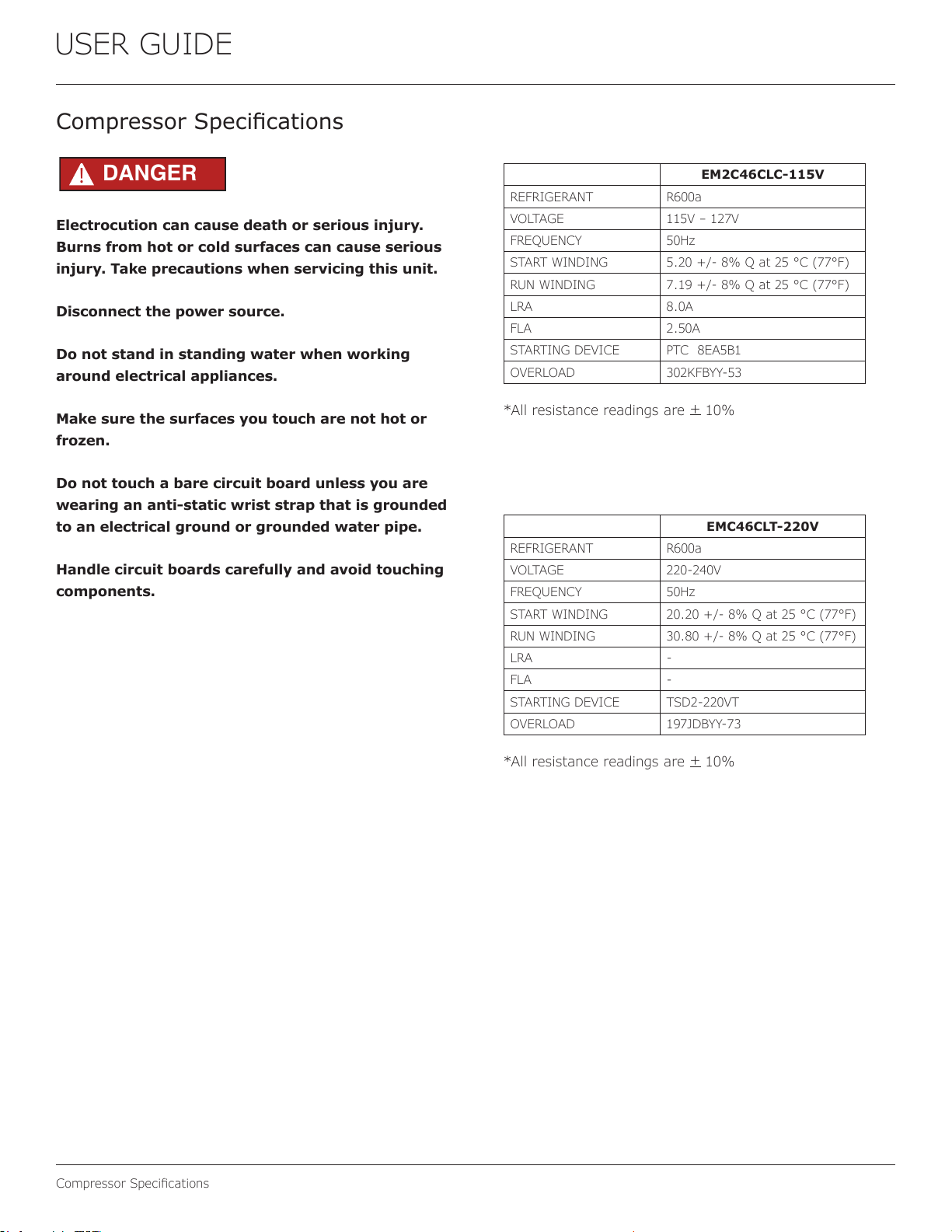
CompressorSpeci�cations
EM2C46CLC-115V
REFRIGERANT R600a
VOLTAGE 115V – 127V
FREQUENCY 50Hz
START WINDING 5.20 +/- 8% Q at 25 °C (77°F)
RUN WINDING 7.19 +/- 8% Q at 25 °C (77°F)
LRA 8.0A
FLA 2.50A
STARTING DEVICE PTC 8EA5B1
OVERLOAD 302KFBYY-53
*All resistance readings are
+
10%
DANGER
!
EMC46CLT-220V
REFRIGERANT R600a
VOLTAGE 220-240V
FREQUENCY 50Hz
START WINDING 20.20 +/- 8% Q at 25 °C (77°F)
RUN WINDING 30.80 +/- 8% Q at 25 °C (77°F)
LRA -
FLA -
STARTING DEVICE TSD2-220VT
OVERLOAD 197JDBYY-73
*All resistance readings are
+
10%
36
USER GUIDE
Troubleshooting Extended
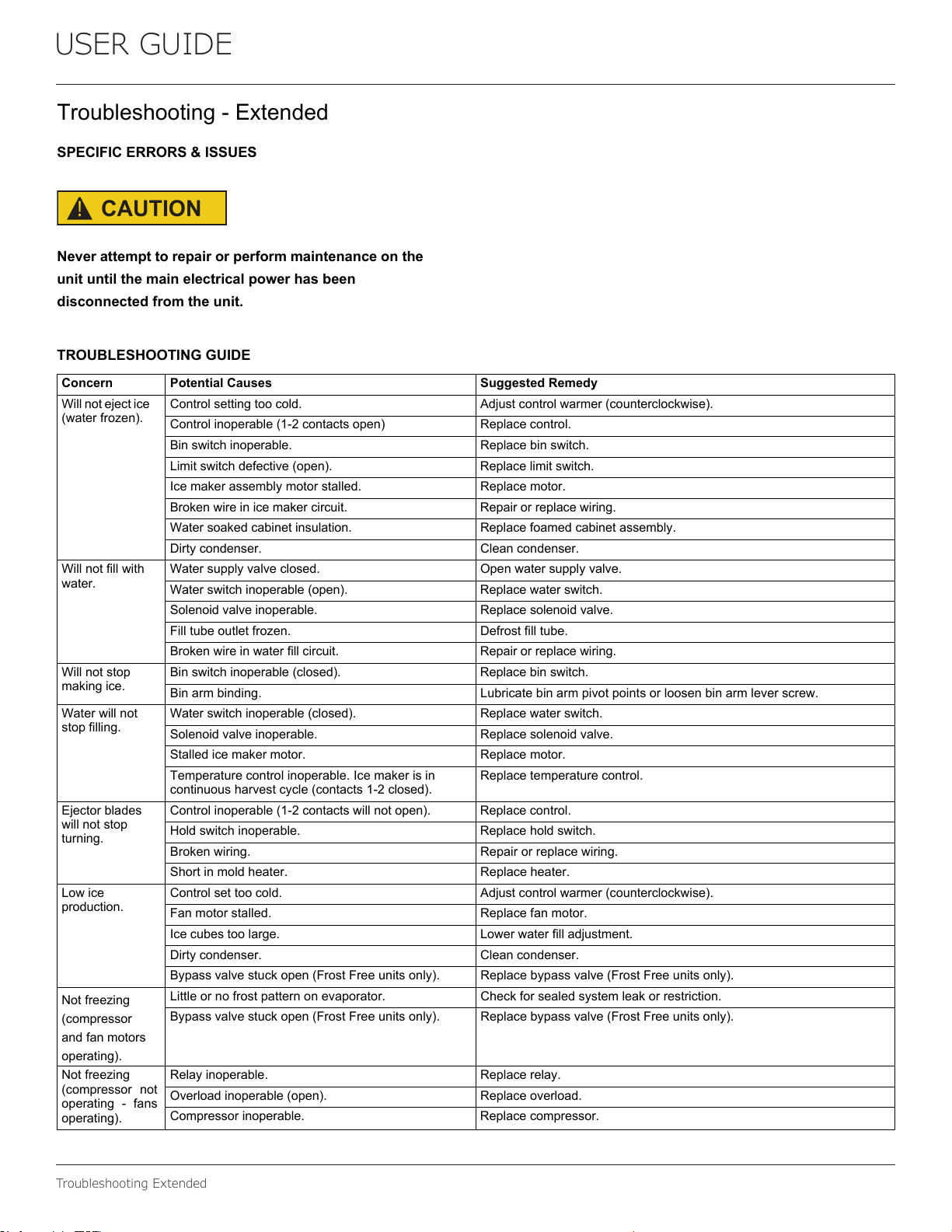
Troubleshooting-Extended
SPECIFICERRORS&ISSUES
!
CAUTION
Neverattempttorepairorperformmaintenanceonthe
unituntilthemainelectricalpowerhasbeen
disconnectedfromtheunit.
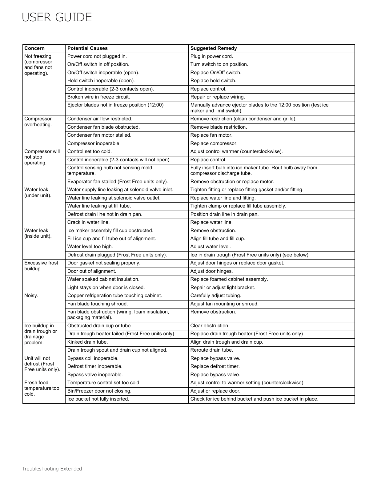
TROUBLESHOOTINGGUIDE
Concern PotentialCauses SuggestedRemedy
Willnotejectice
(waterfrozen).
Controlsettingtoocold. Adjustcontrolwarmer(counterclockwise).
Controlinoperable(1-2contactsopen) Replacecontrol.
Binswitchinoperable. Replacebinswitch.
Limitswitchdefective(open). Replacelimitswitch.
Icemakerassemblymotorstalled. Replacemotor.
Brokenwireinicemakercircuit. Repairorreplacewiring.
Watersoakedcabinetinsulation. Replacefoamedcabinetassembly.
Dirtycondenser. Cleancondenser.
Willnotfillwith
water.
Watersupplyvalveclosed. Openwatersupplyvalve.
Waterswitchinoperable(open). Replacewaterswitch.
Solenoidvalveinoperable. Replacesolenoidvalve.
Filltubeoutletfrozen. Defrostfilltube.
Brokenwireinwaterfillcircuit. Repairorreplacewiring.
Willnotstop
makingice.
Binswitchinoperable(closed). Replacebinswitch.
Binarmbinding. Lubricatebinarmpivotpointsorloosenbinarmleverscrew.
Waterwillnot
stopfilling.
Waterswitchinoperable(closed). Replacewaterswitch.
Solenoidvalveinoperable. Replacesolenoidvalve.
Stalledicemakermotor. Replacemotor.
Temperaturecontrolinoperable.Icemakerisin
continuousharvestcycle(contacts1-2closed).
Replacetemperaturecontrol.
Ejectorblades
willnotstop
turning.
Controlinoperable(1-2contactswillnotopen). Replacecontrol.
Holdswitchinoperable. Replaceholdswitch.
Brokenwiring. Repairorreplacewiring.
Shortinmoldheater. Replaceheater.
Lowice
production.
Controlsettoocold. Adjustcontrolwarmer(counterclockwise).
Fanmotorstalled. Replacefanmotor.
Icecubestoolarge. Lowerwaterfilladjustment.
Dirtycondenser. Cleancondenser.
Bypassvalvestuckopen(FrostFreeunitsonly). Replacebypassvalve(FrostFreeunitsonly).
Notfreezing
(compressor
andfanmotors
operating).
Littleornofrostpatternonevaporator. Checkforsealedsystemleakorrestriction.
Bypassvalvestuckopen(FrostFreeunitsonly). Replacebypassvalve(FrostFreeunitsonly).
Notfreezing
(compressor not
operating - fans
operating).
Relayinoperable. Replacerelay.
Overloadinoperable(open). Replaceoverload.
Compressorinoperable. Replacecompressor.
37
USER GUIDE
Troubleshooting Extended
Notfreezing
(compressor
andfansnot
operating).
Powercordnotpluggedin. Pluginpowercord.
On/Offswitchinoffposition. Turnswitchtoonposition.
On/Offswitchinoperable(open). ReplaceOn/Offswitch.
Holdswitchinoperable(open). Replaceholdswitch.
Controlinoperable(2-3contactsopen). Replacecontrol.
Brokenwireinfreezecircuit. Repairorreplacewiring.
Ejectorbladesnotinfreezeposition(12:00) Manuallyadvanceejectorbladestothe12:00position(testice
makerandlimitswitch).
Compressor
overheating.
Condenserairflowrestricted. Removerestriction(cleancondenserandgrille).
Condenserfanbladeobstructed. Removebladerestriction.
Condenserfanmotorstalled. Replacefanmotor.
Compressorinoperable. Replacecompressor.
Compressorwill
notstop
operating.
Controlsettoocold. Adjustcontrolwarmer(counterclockwise).
Controlinoperable(2-3contactswillnotopen). Replacecontrol.
Controlsensingbulbnotsensingmold
temperature.
Fullyinsertbulbintoicemakertube.Routbulbawayfrom
compressordischargetube.
Evaporatorfanstalled(FrostFreeunitsonly). Removeobstructionorreplacemotor.
Waterleak
(underunit).
Watersupplylineleakingatsolenoidvalveinlet. Tightenfittingorreplacefittinggasketand/orfitting.
Waterlineleakingatsolenoidvalveoutlet. Replacewaterlineandfitting.
Waterlineleakingatfilltube. Tightenclamporreplacefilltubeassembly.
Defrostdrainlinenotindrainpan. Positiondrainlineindrainpan.
Crackinwaterline. Replacewaterline.
Waterleak
(insideunit).
Icemakerassemblyfillcupobstructed. Removeobstruction.
Fillicecupandfilltubeoutofalignment. Alignfilltubeandfillcup.
Waterleveltoohigh. Adjustwaterlevel.
Defrostdrainplugged(FrostFreeunitsonly). Iceindraintrough(FrostFreeunitsonly)(seebelow).
Excessivefrost
buildup.
Doorgasketnotsealingproperly. Adjustdoorhingesorreplacedoorgasket.
Dooroutofalignment. Adjustdoorhinges.
Watersoakedcabinetinsulation. Replacefoamedcabinetassembly.
Lightstaysonwhendoorisclosed. Repairoradjustlightbracket.
Noisy. Copperrefrigerationtubetouchingcabinet. Carefullyadjusttubing.
Fanbladetouchingshroud. Adjustfanmountingorshroud.
Fanbladeobstruction(wiring,foaminsulation,
packagingmaterial).
Removeobstruction.
Icebuildupin
draintroughor
drainage
problem.
Obstructeddraincuportube. Clearobstruction.
Draintroughheaterfailed(FrostFreeunitsonly). Replacedraintroughheater(FrostFreeunitsonly).
Kinkeddraintube. Aligndraintroughanddraincup.
Draintroughspoutanddraincupnotaligned. Reroutedraintube.
Unitwillnot
defrost(Frost
Freeunitsonly).
Bypasscoilinoperable. Replacebypassvalve.
Defrosttimerinoperable. Replacedefrosttimer.
Bypassvalveinoperable. Replacebypassvalve.
Freshfood
temperaturetoo
cold.
Temperaturecontrolsettoocold. Adjustcontroltowarmersetting(counterclockwise).
Bin/Freezerdoornotclosing. Adjustorreplacedoor.
Icebucketnotfullyinserted. Checkforicebehindbucketandpushicebucketinplace.
Concern PotentialCauses SuggestedRemedy
38
USER GUIDE
Troubleshooting Extended
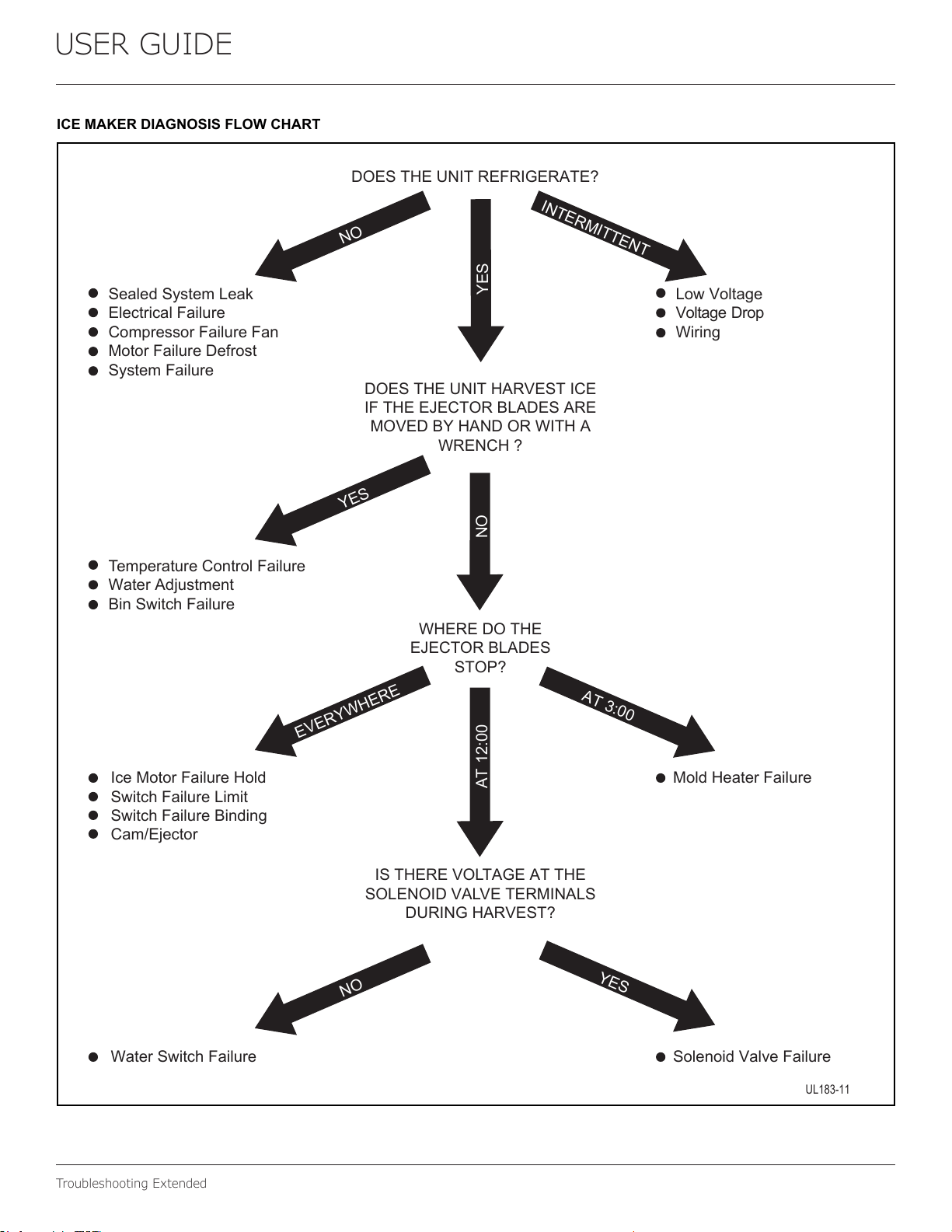
ICEMAKERDIAGNOSISFLOWCHART
DOESTHEUNITREFRIGERATE?
SealedSystemLeak
ElectricalFailure
CompressorFailureFan
MotorFailureDefrost
SystemFailure
LowVoltage
VoltageDrop
Wiring
TemperatureControlFailure
WaterAdjustment
BinSwitchFailure
N
O
N
O
EV
E
R
Y
WHERE
INTERMITTE
N
T
AT
3:
00
Y
E
S
N
O
A
T
12:00
DOESTHEUNITHARVESTICE
IFTHEEJECTORBLADESARE
MOVEDBYHANDORWITHA
WRENCH?
WHEREDOTHE
EJECTORBLADES
STOP?
MoldHeaterFailure
SolenoidValveFailure
IceMotorFailureHold
SwitchFailureLimit
SwitchFailureBinding
Cam/Ejector
WaterSwitchFailure
ISTHEREVOLTAGEATTHE
SOLENOIDVALVETERMINALS
DURINGHARVEST?
UL183-11
Y
ES
YES
39
USER GUIDE
Troubleshooting Extended
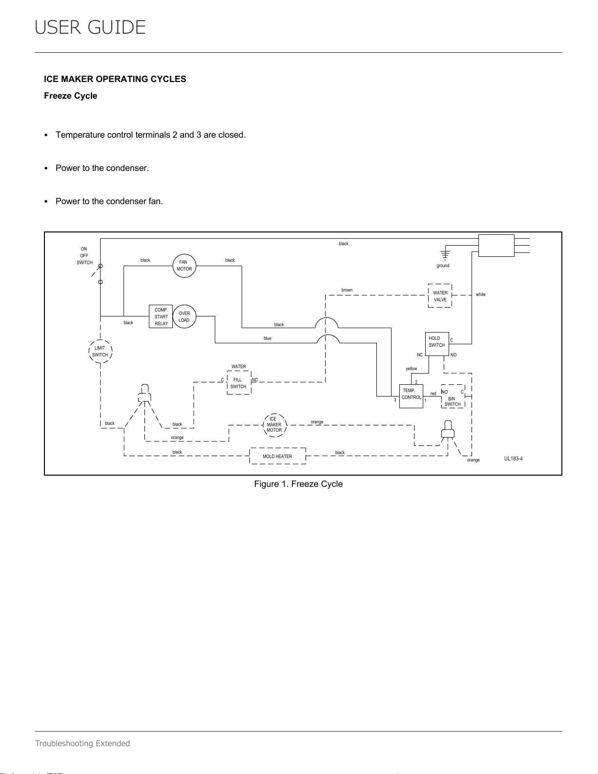
ICEMAKEROPERATINGCYCLES
FreezeCycle
Temperaturecontrolterminals2and3areclosed.
Powertothecondenser.
Powertothecondenserfan.
Figure1.FreezeCycle
SWITCH
LIMIT
orange
black
black
black
MOTOR
MAKER
ICE
MOLDHEATER
WATER
SWITCH
FILLC
NC
MOTOR
FAN
LOAD
OVER
black
RELAY
START
COMP.
SWITCH
OFF
ON
black
black
blue
black
CONTROL
TEMP.
NC
black
orange
3
yellow
2
orange
SWITCH
BIN
red
NO
1
C
NO
brown
black
white
C
SWITCH
HOLD
VALVE
WATER
ground
UL183-4
40
USER GUIDE
Troubleshooting Extended
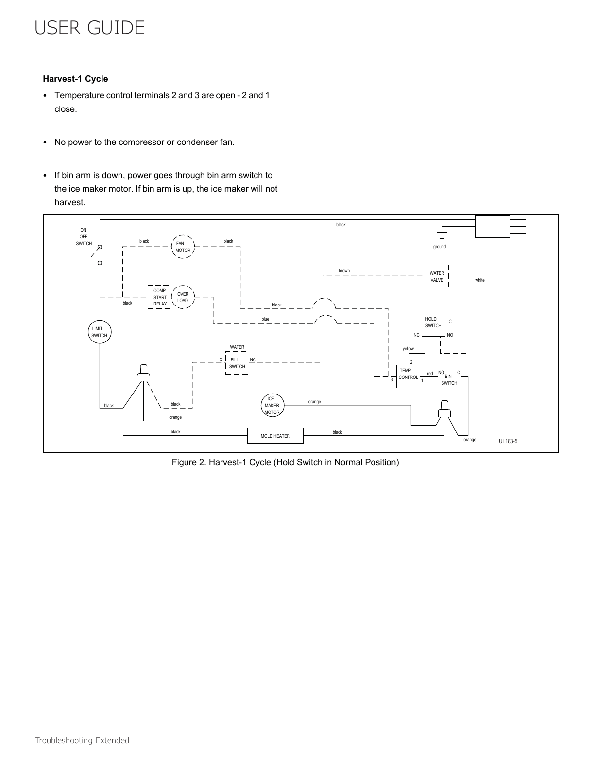
Harvest-1Cycle
Temperaturecontrolterminals2and3areopen-2and1
close.
Nopowertothecompressororcondenserfan.
Ifbinarmisdown,powergoesthroughbinarmswitchto
theicemakermotor.Ifbinarmisup,theicemakerwillnot
harvest.
Figure2.Harvest-1Cycle(HoldSwitchinNormalPosition)
SWITCH
LIMIT
orange
black
black
black
MOTOR
MAKER
ICE
MOLDHEATER
WATER
SWITCH
FILLC
NC
MOTOR
FAN
LOAD
OVER
black
RELAY
START
COMP.
SWITCH
OFF
ON
black
black
blue
black
CONTROL
TEMP.
NC
black
orange
3
yellow
2
orange
SWITCH
BIN
red
NO
1
C
NO
brown
black
white
C
SWITCH
HOLD
VALVE
WATER
ground
UL183-5
41
USER GUIDE
Troubleshooting Extended
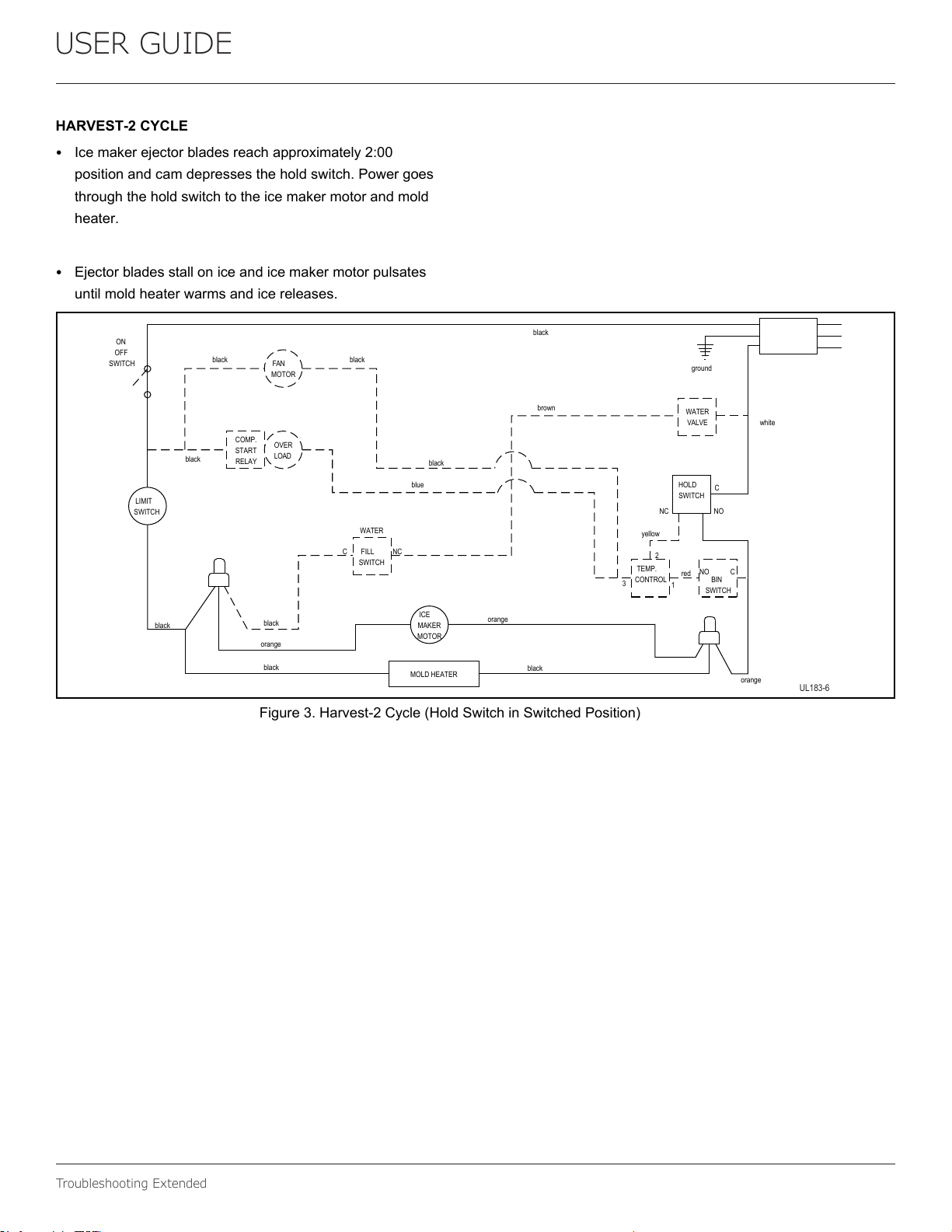
HARVEST-2CYCLE
Icemakerejectorbladesreachapproximately2:00
positionandcamdepressestheholdswitch.Powergoes
throughtheholdswitchtotheicemakermotorandmold
heater.
Ejectorbladesstalloniceandicemakermotorpulsates
untilmoldheaterwarmsandicereleases.
Figure3.Harvest-2Cycle(HoldSwitchinSwitchedPosition)
SWITCH
LIMIT
orange
black
black
black
MOTOR
MAKER
ICE
MOLDHEATER
WATER
SWITCH
FILL
C
NC
MOTOR
FAN
LOAD
OVER
black
RELAY
START
COMP.
SWITCH
OFF
ON
black
black
blue
black
CONTROL
TEMP.
NC
black
orange
3
yellow
2
orange
SWITCH
BIN
red
NO
1
C
NO
brown
black
white
C
SWITCH
HOLD
VALVE
WATER
ground
UL183-6
42
USER GUIDE
Troubleshooting Extended
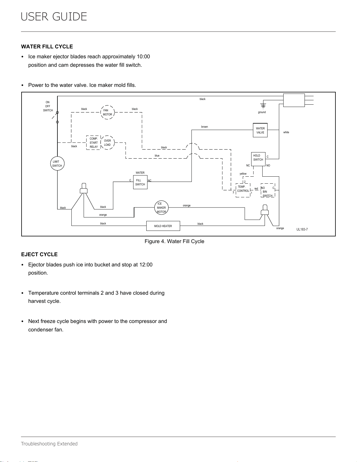
WATERFILLCYCLE
Icemakerejectorbladesreachapproximately10:00
positionandcamdepressesthewaterfillswitch.
Powertothewatervalve.Icemakermoldfills.
Figure4.WaterFillCycle
EJECTCYCLE
Ejectorbladespushiceintobucketandstopat12:00
position.
Temperaturecontrolterminals2and3haveclosedduring
harvestcycle.
Nextfreezecyclebeginswithpowertothecompressorand
condenserfan.
SWITCH
LIMIT
orange
black
black
black
MOTOR
MAKER
ICE
MOLDHEATER
WATER
SWITCH
FILLC
NC
MOTOR
FAN
LOAD
OVER
black
RELAY
START
COMP.
SWITCH
OFF
ON
black
black
blue
black
CONTROL
TEMP.
NC
black
orange
3
yellow
2
orange
SWITCH
BIN
red
NO
1
C
NO
brown
black
white
C
SWITCH
HOLD
VALVE
WATER
ground
UL183-7
43
USER GUIDE
Troubleshooting Extended
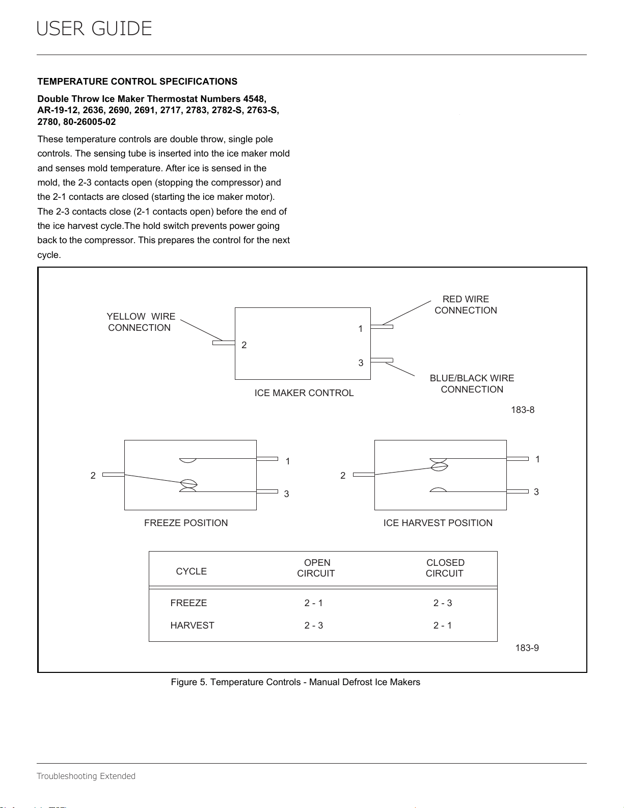
TEMPERATURECONTROLSPECIFICATIONS
DoubleThrowIceMakerThermostatNumbers4548,
AR-19-12,2636,2690,2691,2717,2783,2782-S,2763-S,
2780,80-26005-02
Thesetemperaturecontrolsaredoublethrow,singlepole
controls.Thesensingtubeisinsertedintotheicemakermold
andsensesmoldtemperature.Aftericeissensedinthe
mold,the2-3contactsopen(stoppingthecompressor)and
the2-1contactsareclosed(startingtheicemakermotor).
The2-3contactsclose(2-1contactsopen)beforetheendof
theiceharvestcycle.Theholdswitchpreventspowergoing
backtothecompressor.Thispreparesthecontrolforthenext
cycle.
.
Figure5.TemperatureControls-ManualDefrostIceMakers
YELLOW WIRE
CONNECTION
REDWIRE
CONNECTION
BLUE/BLACKWIRE
CONNECTION
ICEMAKERCONTROL
2
1
3
183-8
2 2
1
3
1
3
FREEZEPOSITION ICEHARVESTPOSITION
CYCLE
CLOSED
CIRCUIT
OPEN
CIRCUIT
FREEZE 2-1 2-3
HARVEST 2-3 2-1
183-9
44
USER GUIDE
Troubleshooting Extended
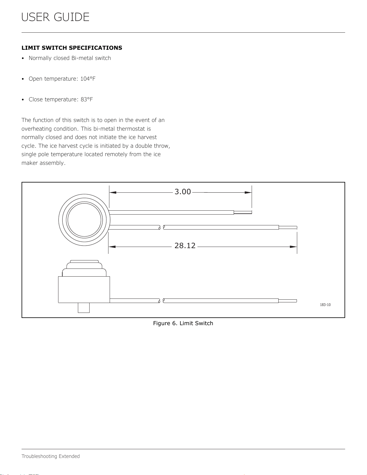
28.12
3.00
183-10
45
USER GUIDE
Troubleshooting Extended
46
USER GUIDE
Troubleshooting Extended
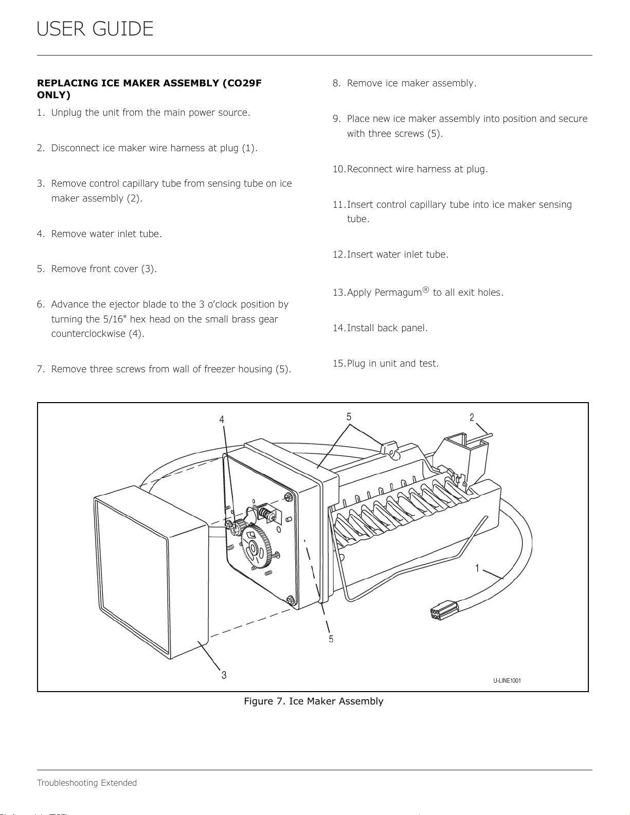
REPLACINGICEMAKERASSEMBLY(ALLMODELS
EXCEPTCO29F)
1. Removebackpanel.
2. Disconnectallwiresatbellconnectors(5wires-Models
BI95,BI98orSP18;orPlug-Models).
3. Removecapillarytubefromsensingtubeonicemaker
assembly(2).
4. Removewaterinlettube.
5. Removefrontcover(3)
6. Advanceejectorbladestothe3:00positionbyturningthe
5/16"hexheadonthesmallbrassgearcounterclockwise
(4).
7. Removetwoscrewsfromthesidewallofevaporator(5).
8. Removescrewsfromthebottomoftheevaporatorplate.
9. Removeicemakerassemblyfromevaporatorshelf.
10. Cleanalumilasticfromevaporatorshelf.
11. Apply1/4"layeroffreshalumilastictoheatersideofnew
icemaker.
12. Replacepartsinreverseorderofremoval.
13. Reconnectallwires.
14. Insertcapillarytubeintoicemakersensingtube.
15. Insertwaterinlettube.
16. Applypermagumtoallexitholes.Mountbackpanel.
17.Mountthebackpanel.
18.Pluginunitandtest.
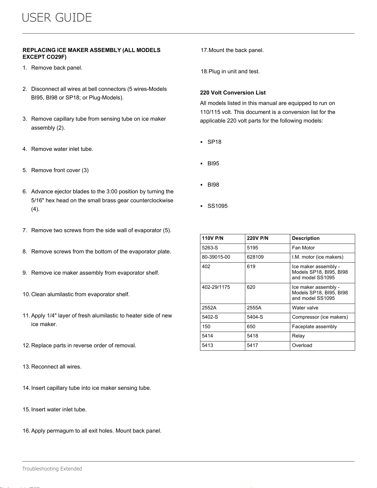
220VoltConversionList
Allmodelslistedinthismanualareequippedtorunon
110/115volt.Thisdocumentisaconversionlistforthe
applicable220voltpartsforthefollowingmodels:
SP18
BI95
BI98
SS1095
110VP/N 220VP/N Description
5263-S 5195 FanMotor
80-39015-00 628109 I.M.motor(icemakers)
402 619 Icemakerassembly-
ModelsSP18,BI95,BI98
andmodelSS1095
402-29/1175 620 Icemakerassembly-
ModelsSP18,BI95,BI98
andmodelSS1095
2552A 2555A Watervalve
5402-S 5404-S Compressor(icemakers)
150 650 Faceplateassembly
5414 5418 Relay
5413 5417 Overload
47
USER GUIDE
Defrost 1
SAFETY INSTALLATION & INTEGRATION OPERATING INSTRUCTIONS MAINTENANCE SERVICE
Defrost
These units are manual defrost.
To defrost unit remove ice bucket. Turn unit off. Use
toweling inside to absorb water as it melts down. This will
help prevent water from getting onto customer’s floor.
The defrost duration is dependent upon usage or climate.
Typically, defrosting is needed approximately every 3-6
weeksand/orwhen1/4"ormoreoffrostispresent-
whichevercomesfirst.
48
CopyrightU-Line Corporation. All Rights Reserved. | Publication Number 30379 | 11/2022 Rev. P
U-LineCorporation(U-Line)LimitedWarranty
OneYearLimitedWarranty
For one year from the date of original purchase, this warranty covers all parts and labor to repair or replace any part of the product that
proves to be defective in materials or workmanship. For products installed and used for normal residential use, material cosmetic defects
are included in this warranty, with coverage limited to 60 days from the date of original purchase. All service provided by U-Line under the
above warranty must be performed by a U-Line factory authorized servicer, unless otherwise specified by U-Line. Service provided during
normal business hours.
TwoYearLimitedWarranty(5ClassProduct)
For two years from the date of original purchase, this warranty covers all parts and labor to repair or replace any part of the product that
proves to be defective in materials or workmanship. For products installed and used for normal residential use, material cosmetic defects
are included in this warranty, with coverage limited to 60 days from the date of original purchase. All service provided by U-Line under the
above warranty must be performed by a U-Line factory authorized servicer, unless otherwise specified by U-Line. Service provided during
normal business hours.
AvailableSecond&ThirdYearLimitedWarranty
In addition to the standard one and two year warranties outlined above, U-Line offers a one year extension of the warranties from the date
of purchase, free of charge. To take advantage of this extension, you must register your product with U-Line within 60 days from the date
of purchase at u-line.com and provide proof of purchase.NuggetIceMachineproofofpurchasemustincludethepurchaseofanin-line
waterfilterandfilterheadtoqualifyforthisadditionallimitedwarranty.
FiveYearSealedSystemLimitedWarranty
For five years from the date of original purchase, U-Line will repair or replace the following parts, labor not included, that prove to be
defective in materials or workmanship: compressor, condenser, evaporator, drier, and all connecting tubing. All service provided by U-Line
under the above warranty must be performed by a U-Line factory authorized servicer, unless otherwise specified by U-Line. Service
provided during normal business hours.
Terms
These warranties apply only to products installed in any one of the fifty states of the United States, the District of Columbia, or the ten
provinces of Canada. The warranties do not cover any parts or labor to correct any defect caused by negligence, accident or improper use,
maintenance, installation, service, repair, acts of God, fire, flood or other natural disasters. The product must be installed, operated, and
maintained in accordance with your product’s User Guide.
The remedies described above for each warranty are the only ones that U-Line will provide, either under these warranties or under any
warranty arising by operation of law. U-Line will not be responsible for any consequential or incidental damages arising from the breach of
these warranties or any other warranty, whether express, implied, or statutory. Some states do not allow the exclusion or limitation of
incidental or consequential damages, so the above limitation or exclusion may not apply to you. These warranties give you specific legal
rights, and you may also have other rights which vary from state to state.
Any warranty that may be implied in connection with your purchase or use of the product, including any warranty of merchantability or any
warranty fit for a particular purpose is limited to the duration of these warranties, and only extends to five years in duration for the parts
described in the section related to the five year limited warranty above. Some states do not allow limitations on how long an implied warranty
lasts, so the above limitations may not apply to you.
• The warranties only apply to the original purchaser and are non-transferable.
• The second, third, and five year warranties cover products installed and used for normal residential or designated marine use only.
• The warranties apply to units operated outside only if designed for outdoor use by model and serial number.
• U-Line Commercial products are covered by the one year and 5 year limited warranties and are not eligible for the second and
third year limited warranties.
• Replacement water filters, light bulbs, and other consumable parts are not covered by these warranties.
• The start of U-Line’s obligation is limited to four years after the shipment date from U-Line.
• In-home instruction on how to use your product is not covered by these warranties.
• Food, beverage, and medicine loss are not covered by these warranties.
• If the product is located in an area where U-Line factory authorized service is not available, you may be responsible for a trip
charge or you may be required to bring the product to a U-Line factory authorized service location at your own cost and expense.
• Units purchased after use as floor displays, and/or certified reconditioned units, are covered by the limited one year warranty only
and no coverage is provided for cosmetic defects.
• Signal issues related to Wi-Fi connectivity are not covered by these warranties.
For parts and service assistance, or to find U-Line factory authorized service near you, contact U-Line:
8900 N. 55
th
Street,Milwaukee,WI53223•u-line.com•onlineservice@u-line.com•+1.414.354.0300
49