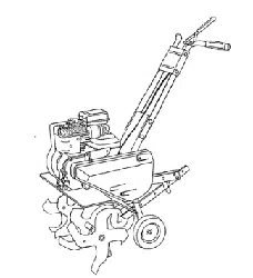
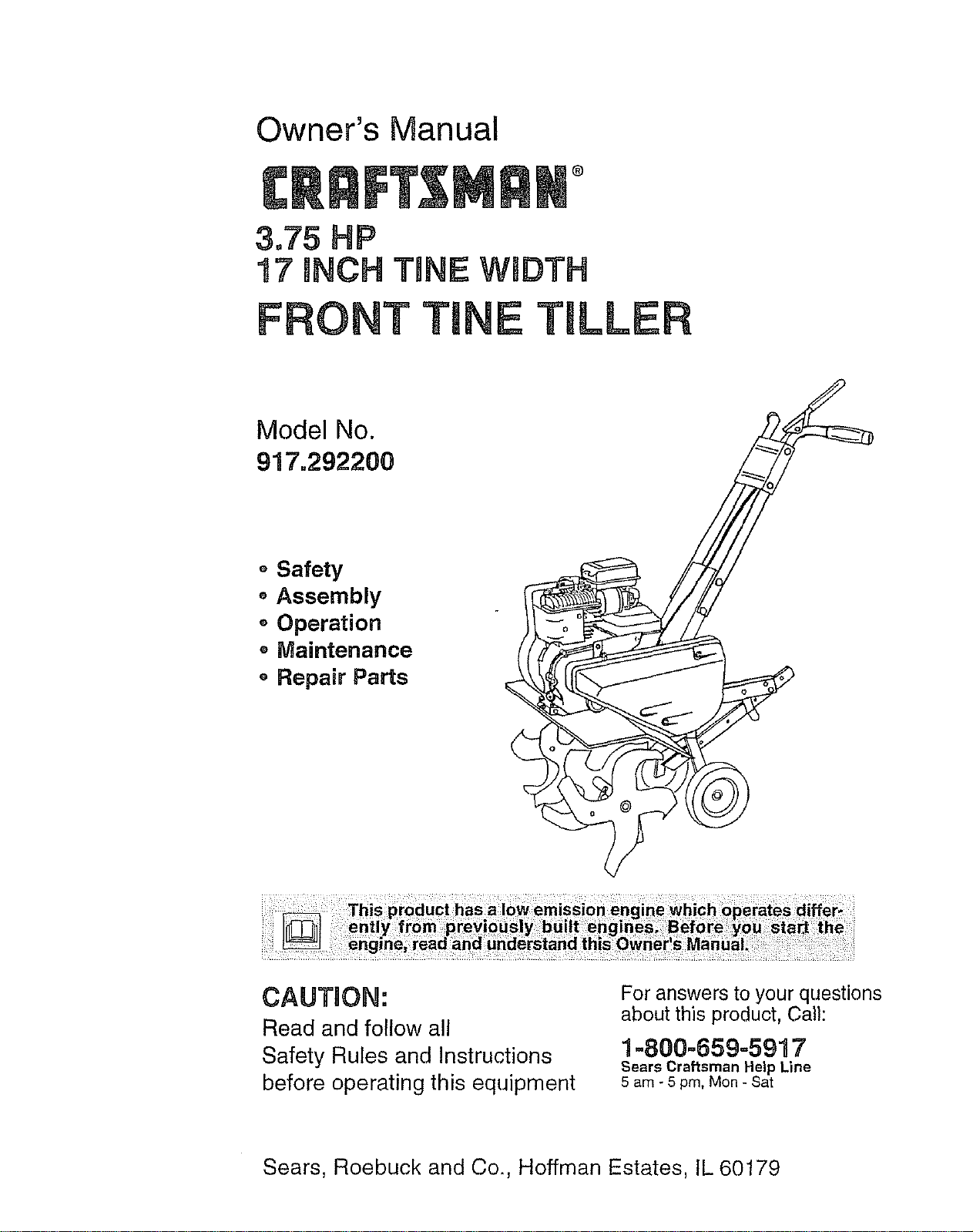
Owner's Manual
®
3.75 HP
17 INCH TmNEWmDTH
FRONT "FINE TILLER
Model No.
917.292200
o Safety
• Assembly
o Operation
o Maintenance
o Repair Parts
CAUTION:
Read and follow all
Safety Rules and Instructions
before operating this equipment
For answers to your questions
about this product, Call:
1.-800-659=5917
Sears Craftsman Help Line
5 am - 5 pm, Mon - Sat
Sears, Roebuck and Co,, Hoffman Estates, IL 60179
Safety Rules ................................................ 2
Warranty ..................................................... 2
Product Specifications ................................4
Assembly ................................................. 6
Operation ..................................................... 7
Maintenance._ ........................................ 11
Service and Adjustments ........................ 13
Storage ..................................................... 16
Troubleshooting ...................................... 18
Illustrated Parts List ............................... 20
Parts Ordering ........................... Back Cover
LIMITED ONE YEAR WARRANTY ON CRAFTSMAN TILLER
For one (1) year from date of purchase, when this Craftsman Tiller is maintained, lubri-
cated, and tuned up according to the operating and maintenance instructions in the
owner's manual, Sears will repair free of charge any defect in material or workmanship.
This Warranty does not cover:
,, Expendable items which become worn during normal use, such as tines, spark plugs,
air cleaners and belts.
• Repairs necessary because of operator abuse or negligence, including bent crank-
shafts and the failure to maintain the equipment according to the instructions con-
tained in the owner's manual
o If this Craftsman Tiller is used for commercial or rental purposes, this Warranty
applies for only thirty (30) days from the date of purchase.
Warranty service is available by returning the craftsman power mower to the nearest
sears service center/department in the united states. This warranty applies only while
this product is in use in the united states°
This Warranty gives you specific legal rights, and you may also have other rights which
vary from state to state.
SEARS, ROEBUCKAND CO., D/817WA, HOFFMAN ESTATES, IL 60179
TRAINING
o Read the Owner's Manual carefully. Be
thoroughly familiar with the controls and
the proper use of the equipment. Know
how to stop the unit and disengage the
controls quickly.
° Never allow children to operate the
equipment Never allow adults to oper-
ate the equipment without proper
instruction..
• Keep the area of operation clear of all
persons, particularly small children, and
pets.
PREPARATION
o Thoroughly inspect the area where the
equipment is to be used and remove all
foreign objects.
o Disengage all clutches and shift into
neutral before starting the engine (mo-
tor).
° Do not operate the equipment without
wearing adequate outer garments. Wear
footwear that will improve footing on
slippery surfaces.
= Handle fuel with care; it is highly flam-
mable..
• Use an approved fuel container.
o Never add fuel to a running engine or
hot engine.
o Fill fuel tank outdoors with extreme
care_ Never fill fuel tank indoors.
o Replace gasoline cap securely and
clean up spilled fuel before restarting.
o Use extension cords and receptacles as
specified by the manufacturer for all
units with electric drive motors or elec-
tric starting motors.
° Never attempt to make any adjustments
while the engine (motor) is running
(except where specifically recommend-
ed by manufacturer).
2
OPERATION
o Do not put hands or feet near or under
rotating pad&
o Exercise extreme caution when operat-
ing on or crossing gravel drives, walks,
or roads. Stay alert for hidden hazards
or traffic. Do not carry passengers.
o After striking a foreign object, stop the
engine (motor), remove the wire from
the spark plug, thoroughly inspect the
tiller for any damage, and repair the
damage before restarting and operating
the tiller..
,, Exercise caution to avoid slipping or
falling.
o If the unit should start to vibrate abnor-
mally, stop the engine (motor) and check
immediately for the cause.. Vibration is
generally a warning of trouble.
o Stop the engine (motor) when leaving
the operating position.
° Take all possible precautions when leav-
ing the machine unattende& Disengage
the tines, shift into neutral, and stop the
engine.
° Before cleaning, repairing, or inspecting,
shut off the engine and make certain all
moving parts have stopped. Disconnect
the spark plug wire, and keep the wire
away from the plug to prevent accidental
starting.. Disconnect the cord on electric
motor&
- Do not run the engine indoors; exhaust
fumes are dangerous.
• Never operate the tiller without proper
guards, plates, or other safety protective
devices in place..
,, Keep children and pets away.
o Do not overload the machine capacity
by attempting to till too deep at too fast a
rate
• Never operate the machine at high
speeds on slippery surfaces Look
behind and use care when backing.
= Never allow bystanders near the unit.
° Use only attachments and accessories
approved by the manufacturer of the
tiller (such as wheel weights, counter-
weights, cabs, and the like)
,, Never operate the tiller without good vis-
ibility or lighL
• Be careful when tilling in hard ground_
The tines may catch in the ground and
propel the tiller forward. If this occurs,
let go of the handlebars and do not
restrain the machine.
MAINTENANCE AND STORAGE
• Keep machine, attachments, and
accessories in safe working condition..
o Check shear pins, engine mounting
bolts, and other bolts at frequent inter-
vals for proper tightness to be sure the
equipment is in safe working condition.
o Never store the machine with fuel in th_
fuel tank inside a building where ignitiol
sources are present, such as hot water
and space heaters, clothes dryers, and
the like. Allow the engine to cool before
storing in any enclosure.
o Always refer to the operator's guide
instructions for important details if the
tiller is to be stored for an extended pel
od.
_CAUTION: Always disconnect spark
plug wire and place wire where it cannot
contact spark plug in order to prevent ace
dental starting when setting up, transport
i_, adjusting or making repairs.
WARNING: The engine exhuast from
this product contains chemicals known to
the State of California to cause cancer,
birth defectd, or other reproductive harm.
3
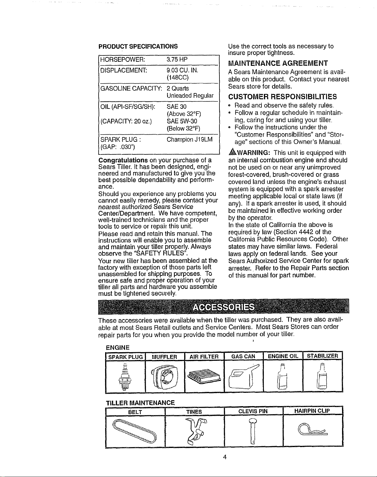
PRODUCT SPECIFICATIONS
HORSEPOWER: 3.75 HP
I--
DISPLACEMENT: 9.03 CU_IN.
(148CC)
GASOLINE CAPACITY: 2 Quarts
Unleaded Regular
OIL (API-SF/SG/SH): SAE 30
(Above 32°F)
CAPACITY: 20 oz.) SAE 5W-30
(Below 32°F)
SPARK PLUG : Champion J19LM
GAP: .030")
Congratulations on your purchase of a
Sears Tiller. It has been designed, engi-
neered and manufactured to give you the
best possible dependability and perform-
ance.
Should you experience any problems you
cannot easily remedy, please contact your
nearest authorized Sears Service
CentedDepartment. We have competent,
well-trained technicians and the proper
tools to service or repair this unit.
Please read and retain this manual The
instructions will enable you to assemble
and maintain your tiller properly, Always
observe the "SAFETY RULES".
Your new tiller' has been assernbled at the
factory with exception of those parts left
unassembled for shipping purposes. To
ensure safe and proper operation of your
tiller all parts and hardware you assemble
must be tightened securely.
Use the correct tools as necessary to
insure proper tightness.
MAINTENANCE AGREEMENT
A Sears Maintenance Agreement is avail-
able on this product. Corrtact your nearest
Sears store for details.
CUSTOMER RESPONSIBILITIES
o Read and observe the safety rules..
o Follow a regular schedule in maintain-
ing, cadng for and using your tiller.
o Follow the instructions under the
"Customer Responsibilities" and "Stor-
age" sections of this Owner's Manual
,_kWARNING: This unit is equipped with
an internal combustion engine and should
not be used on or near any unimproved
forest-covered, brush-covered or grass
covered land unless the engine's exhaust
system is equipped with a spark arrester
meeting applicable local or state laws (if
any). If a spark arrester is used, it should
be maintained in effective working order
by the operator.
In the state of California the above is
required ;by law (Section 4442 of the
California Public Resources Code) Other
states may have similar laws. Federal
laws apply on federal lands. See your
Sears Authorized Service Center for spark
arrestor. Refer to the Repair Parts section
of this manual for part number..
These accessories wer e available when the tiller was purchased. They are also avail-
able at most Sears Retail outlets and Service Center& Most Sears Stores can order
repair parts for you when you provide the model number of your tiller
f
-NGINE
"MUFFLER AIR FILTER GAS CAN ENGINE,OIL"' STABILIZER
TILLER MAINTENANCE
BELT 'TINES
i,i ii , H Illl
CLEV,!,SPIN HAIRPIN CLIP
4
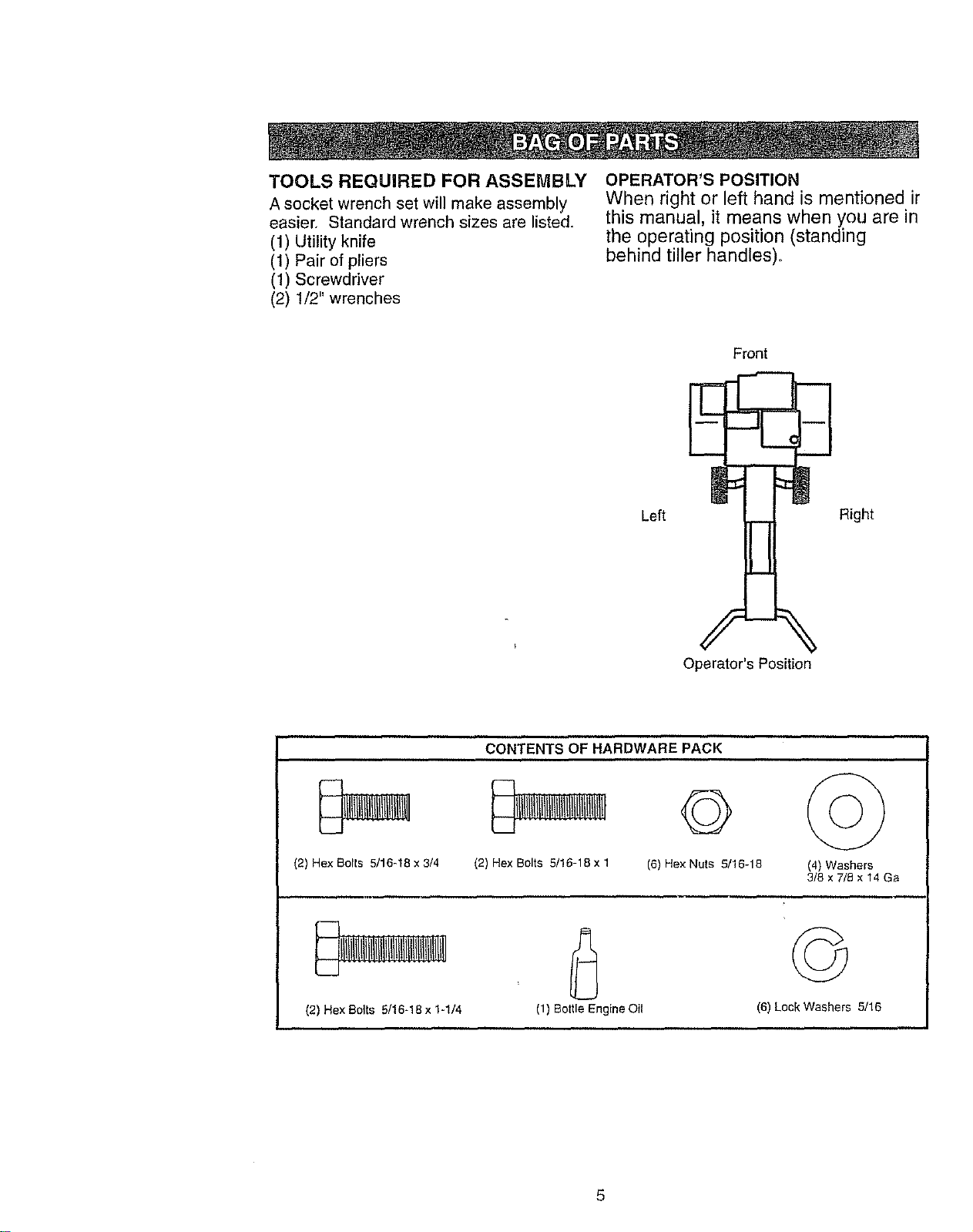
TOOLS REQUIRED FOR ASSEMBLY
A socket wrench set will make assembly
easier, Standard wrench sizes are listed,
(1) Utility knife
(1) Pair of pliers
(1) Screwdriver
(2) 1/2" wrenches
OPERATOR'S POSITION
When right or left hand is mentioned ir
this manual, it means when you are in
the operating position (standing
behind tiller handles)°
Left
E
!
Front
J
Right
Operator's Position
(2) Hex Bolts 5/16-18 x 3/4
(2) Hex Bolts 5116-18 x 1-1/4
CONTENTS OF HARDWARE PACK
(2) Hex Bolts 5/16-18 x 1
G ©
(6) Hex Nuts 5/16-18 (4) Washers
3/8 x 7/5 x 14 Ga
. ,,, , *
(1) Bottle Engine Oil
(6) Lock Washers 5/16
5
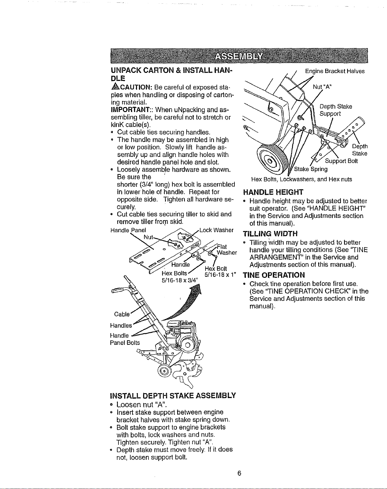
UNPACK CARTON & INSTALL HAN-
DLE
_CAUTION: Be careful of exposed sta-
ples when handling or disposing of carton-
ing material.
IMPORTANT:: When uNpacking and as-
sembling tiller, be careful not to stretch or
kinK cable(s).
= Cut cable ties securing handles.
o The handle may be assembled in high
or low position,, Slowly lift handle as-
sembly up and align handle holes with
desired handle panel hole and slot.
= Loosely assemble hardware as shown.
Be sure the "
shorter (3/4" long) hex bolt is assembled
in lower hole of handle, Repeat for
opposite side. Tighten all hardware se-
curely.
o Cut cable ties securing tiller to skid and
remove tiller from skid,
Handle Panel _ ..Lock Washer
v I-rex_ol[s-" 5/16-18 x 1
5/16-18 x 3/4"
Hex Bolt_
Engine Bracket Halves
Nut "A"
/
Depth Stake
Support
_X Stake
b/ Support Bolt
Stake Spring
Lockwashers, and Hex nuts
HANDLE HEIGHT
o Handle height may be adjusted to better
suit operator: (See "HANDLE HEIGHT"
in the Service and Adjustments section
of this manual).
TILLING WIDTH
= Tilling Width may be adjusted to better
handle your tilling conditions (See "TINE
ARRANGEMENT' in the Service and
Adjustments section of this manual)°
TINE OPERATION
o Check tine operation before first use,
(See 'q'INE OPERATION CHECK" in the
Service and Adjustments section of this
manual),
Handle
Panel Bolts
INSTALL DEPTH STAKE ASSEMBLY
o Loosen nut "A".
o Insert stake support between engine
bracket halves with stake spring down,
o Bolt stake support to engine brackets
with bolts, lock washers and nuts.
Tighten securely, Tighten nut "A",
• Depth stake must move freely. If it does
not, loosen support bolt.
6
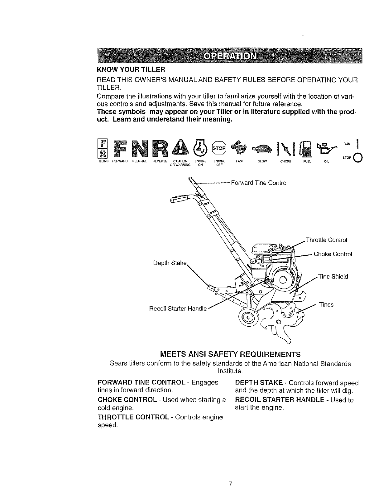
KNOWYOURTILLER
READTHISOWNER'SMANUALANDSAFETYRULESBEFOREOPERATINGYOUR
TILLER,
Comparetheillustrationswithyourtillertofamiliarizeyourselfwiththelocationofvari-
ouscontrolsandadjustments.Savethismanualforfuturereference.
Thesesymbols mayappear on your Tilleror in literature suppliedwith the prod-
uct. Learnandunderstand their meaning.
TILLING FORWARD NEUTRAL REVERSE CAUTION ENGINE ENGINE FAST SLOW CHOKE FUEL OIL
OR WARNING ON OFF
rward Tine Control
Recoil Starter Handle_ __
t" Throttle Control
Choke Control
_...,.,,,./Tine Shield
2
.- Tines
MEETS ANSI SAFETY REQUIREMENTS
Sears tillers conform to the safety standards of the American National Standards
Institute
FORWARD TINE CONTROL - Engages
tines in forward direction
CHOKE CONTROL - Used when starting a
cold engine.
THROTTLE CONTROL - Controls engine
speed.
DEPTH STAKE - Controls forward speed
and the depth at which the tiller will dig,
RECOIL STARTER HANDLE - Used to
start the engine,
7
Theoperationof anytillercanresultinforeignobjectsthrownintotheeyes,
whichcanresultin severeeyedamage.Alwayswearsafetyglassesoreye
shieldsbeforestartingyourtillerandwhiletilling,Werecommendawidevision
safetymaskoverthespectaclesorstandardsafetyglasses.
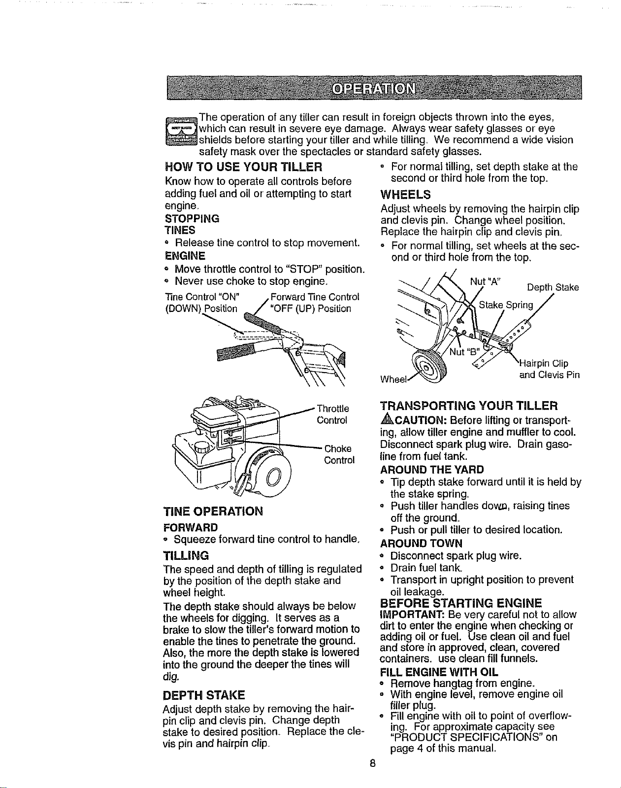
HOW TO USE YOUR TILLER
Know how to operate all controls before
adding fuel and oil or attempting to start
engine_
STOPPING
TINES
• Release tine control to stop movement.
ENGINE
o Move throttle control to "STOP" position.
o Never use choke to stop engine.
"SneControl "ON" /" Forward Tine Control
(DOWN) Position _ / ""OFF(UP) Position
o For normal tilling, set depth stake at the
second or third hole from the top,
WHEELS
Adjust wheels by removing the hairpin clip
and clovis pin, Change wheel position.
Replace the hairpin clip and clevis pin_
. For normal tilling, set wheels at the sec-
ond or third hole from the top_
Wheel
_C 'A'' Depth Stake
lip
end Clevis Pin
/ Throttle
Control
TINE OPERATION
FORWARD
° Squeeze forward tine control to handle.
TILLING
The speed and depth of tilling is regulated
by the position of the depth stake and
wheel height.
The depth stake should always be below
the wheels for digging. It serves as a
brake to slow the tiller's forward motion to
enable the tines to penetrate the ground.
Also,the more the depth stake is lowered
intothe groundthe deeper the tines will
dig.
DEPTH STAKE
Adjust depth stake by removing the hair_
pin clip and clevis pin. Change depth
stake to desired position° Replace the cle-
vis pin and hairpin clip=
TRANSPORTING YOUR TILLER
_,CAUTION: Before lifting or transport-
ing, allow tiller engine and muffler to cool.
Disconnect spark plug wire. Drain gaso-
line from fuel tank.
AROUND THE YARD
= Tip depth stake forward until it is held by
the stake spring.
o Push tiller handles dow._, raising tines
off the ground.
o Push or pull tiller to desired location.
AROUND TOWN
o Disconnect spark plug wire.
o Drain fuel tank_
= Transport in upright position to prevent
oil leakage.
BEFORE STARTING ENGINE
IMPORTANT: Be very careful not to allow
dirt to enter the engine when checking or
adding oil or fuel. Use clean oil and fuel
and store in approved, clean, covered
containers, use clean fill funnels.
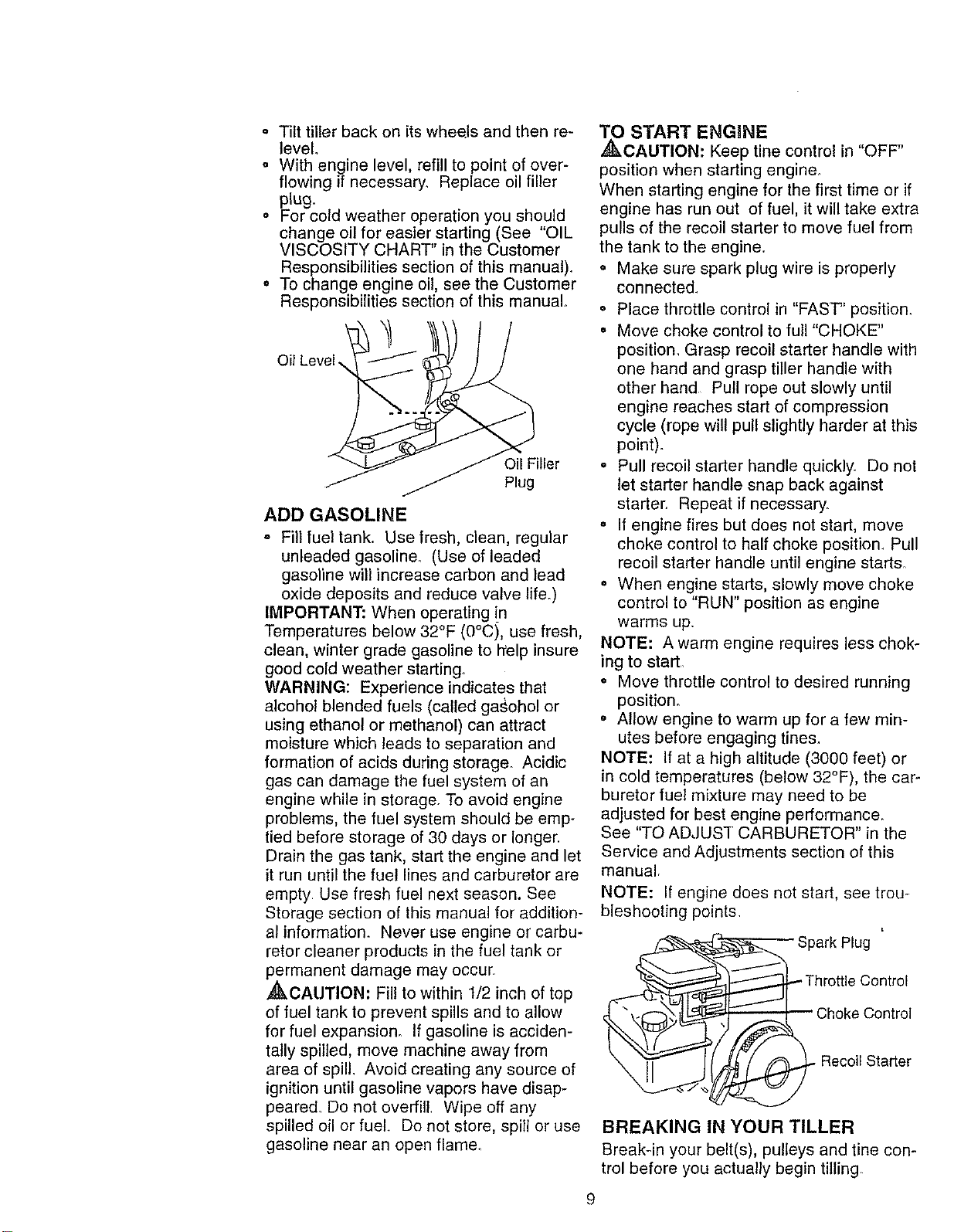
FILL ENGINE WITH OIL
o Remove hangtag from engine=
o With engine level, remove engine oil
filler plug.
o Fill engine with oil to point of overflow-
ing. For approximate capacity see
"PRODUCT SPECIFICATIONS on
page 4 of this manual=
8
" Tilttillerbackonitswhe_lsandthenre-
level
o Withenginelevel,refilltopointofover-
flowingifnecessary.Replaceoilfiller
plug.
o Forcoldweatheroperationyoushould
changeoilforeasierstarting(See "OIL
VISCOSITYCHART intheCustomer
Responsibilitiessectionofthismanual).
o Tochangeengineoil,seetheCustomer
Responsibilitiessectionofthismanual°
OilLevel.
Filler
Plug
ADD GASOLINE
= Fill fuel tank. Use fresh, clean, regular
unleaded gasoline. (Use of leaded
gasoline will increase carbon and lead
oxide deposits and reduce valve life.)
IMPORTANT: When operating in
Temperatures below 32°F (0°C), use fresh,
clean, winter grade gasoline to help insure
good cold weather starting_
WARNING: Experience indicates that
alcohol blended fuels (called gasohol or
using ethanol or methanol) can attract
moisture which leads to separation and
formation of acids during storage. Acidic
gas can damage the fuel system of an
engine while in storage. To avoid engine
problems, the fuel system should be emp-
tied before storage of 30 days or longer.
Drain the gas tank, start the engine and let
it run until the fuel lines and carburetor are
empty Use fresh fuel next season. See
Storage section of this manual for addition-
al information. Never use engine or carbu-
retor cleaner products in the fuel tank or
permanent damage may occur
,_CAUTION: Fil! to within t/2 inch of top
of fuel tank to prevent spills and to allow
for fuel expansion. If gasoline is acciden-
tally spilled, move machine away from
area of spill, Avoid creating any source of
ignition until gasoline vapors have disap-
peared. Do not overfill. Wipe off any
spilled oil or fuel. Do not store, spill or use
gasoline near an open flame.
9
_ START ENGINE
CAUTION: Keep tine control in "OFF"
position when starting engine°
When starting engine for the first time or if
engine has run out of fuel, it will take extra
pulls of the recoil starter to move fuel from
the tank to the engine.
o Make sure spark plug wire is properly
connecte&
• Place throttle control in "FAST' position.
• Move choke control to full "CHOKE"
position, Grasp recoil starter handle with
one hand and grasp tiller handle with
other hand Pull rope out slowly until
engine reaches start of compression
cycle (rope will pull slightly harder at this
point).
o Pull recoil starter handle quickly. Do not
let starter handle snap back against
starter. Repeat if necessary.
• If engine fires but does net start, move
choke control to half choke position. Pull
recoil starter handle until engine starts.
° When engine starts, slowly move choke
control to "RUN" position as engine
warms up.
NOTE: A warm engine requires less chok-
ing to start.
o Move throttle control to desired running
position.
o Allow engine to warm up for a few min-
utes before engaging tine&
NOTE: If at a high altitude (3000 feet) or
in cold temperatures (below 32°F), the car-
buretor fuel mixture may need to be
adjusted for best engine performance.
See "TO ADJUST CARBURETOR" in the
Service and Adjustments section of this
manual.
NOTE: If engine does not start, see trou-
bleshooting points,
Plug
Control
. Recoil Starter
BREAKING IN YOUR TILLER
Break-in your belt(s), pulleys and tine con-
trol before you actually begin tilling
o Start engine, tip tines off ground by
pressing handles down and engage tine
control to start fine rotation. Allow tines
to rotate for five minutes.
o Check tine operation and adjust if nec-
essary. See '%INE OPERATION
CHECK" in the Service and Adjustments
section of this manual.
TILLING HINTS
CAUTION: Until you are accustomed to
handling your tiller, start actual field use
with throttle in slow position (mid-way be-
tween "FAST" and "IDLE").
To help tiller move forward, lift up the ham
dies slightly (thus lifting depth stake out of
ground)° To slow down the tiller, press
down on handles.
If you are straining or tiller is shaking, the
wheels and depth stake are not set prop-
erly in the soil being tilled. The proper set-
ting of the wheels and depth stake is
through trial and error' and depends upon
the soil condition. ('['he harder or wetter
the ground, the slower the engine and tine
speed needed° Under these poor condi-
tions, at fast speed the tiller will run and
jump over the ground)_
A properly adjusted tiller will dig with little
effort from the operator.
= Tilling is digging into, turning over, and
breaking up packed soil before planting.
Loose, unpacked soil helps root growth.
Best tilling depth is 4" to 6'L A tiller will
also clear the soil of unwanted vegeta-
tion. The decomposition of this veg-
etable matter enriches the soil.
Depending on the climate (rainfall and
wind), it may be advisable to till the soil
at the end of the growing season to fur-
ther condition the soil
o Soil conditions are important for proper
tilling_ Tines will not readily penetrate
dry, hard soil which may contribute to
excessive bounce and difficult handling
of your tiller. Hard soil should be mois-
tened before tilling; however, extremely
wet soil will "ball-up" or clump during till-.
ing. Wait until the soil is less wet in order
to achieve the best results. When tilling
in the fall, remove vines and long grass
to prevent them from wrapping around
the tine shaft and slowing your tilling
operation.
o You will find tilling much easier if you
leave a row untilled between passes.
10
Then go back over the entire area at
right angles. There are two reasons for
doing this. First, wide turns are much
easier to negotiate than about-faces_
Second, the tiller won't be pulling itself,
and you, toward the row next to ito
Set depth stake and wheel height for
shallow tilling when working extremely
hard soil or' sod. Then work across the
first cuts at normal depth..
_( I'll H,I I_1 I_1 I'H I,l-I t_1 t_1 I'_1
t .1I -I I ,1i'l'l I ,1 t,H
_( I'll I_1 l_1 I$1 I'H I,H i'll I_1 H'I
__ I'll 1"_ttt'1 H,I I_1_'1 l'tl 1_! t_1 3_1
CULTIVATING
Cultivating is destroying the weeds
between rows to prevent them from rob-
bing nourishment and moisture from the
plants.. Af the same time, breaking up the
upper layer of soil crust will help retain
moisture in the soilo Best digging depth is
1" to 3".
You will probably not need to use the
depth stake= Begin by tipping the depth
stake forward until itis held by the stake
spdng.
Cultivate up and down the rows at a
speed which will allow tines to uproot
weeds and leave the ground in rough
condition, promoting no further
growth of weeds and grass.
OOiO©O
MAINTENANCE _
SCHEDULE
-b ¢o
ILLOATES
REGULAR SERVICE
Check Engine Oil Level _ I_
Change Engine Oi! 6_'1,2
Oil Pivot Points
Inspect Spark Arrestor / Muffler
Inspect Air Screen
Clean or Replace Air Cleaner Cartridge i6/2
Clean Engine Cylinder Fins 6,4"
Replace Spark Plug j 6/
SERVICE DATES
1- Change more often when operating under a heavy load orIn high ambient temperatures
2 - Service more often when operating In dirty or dusly conditions
GENERAL RECOMMENDATIONS
The warranty on this tiller does not cover
items that have been subjected to opera-
tor abuse or negligence,, To receive full
value from the warranty, operator must
maintain tiller as instructed in this manual
Some adjustments will need to be made
periodically to properly maintain your tiller.
All adjustments in the Service and
Adjustments section of this manual should
be checked at least once each season.
o Once a year you should replace the
spark plug, clean or replace air filter,
and check tines and belt for wear A
new spark plug and clean air filter
assure proper air-fuel mixture and help
your engine run better and last longer.
BEFORE EACH USE
o Check engine oil level.
• Check tine operation.
• Check for loose fasteners.
LUBRICATION
Keep unit well lubricated (See "LUBRICA-
TION CHART").
LUBRICATION CHART
* Tine
** Engine
*Idler Arm
* SAE 30 OR 10W30 MOTOR OIL
** REFER TO CUSTOMER RESPONSIBILI-
TIES "ENGINE " SECTION.
11
Disconnectsparkplugwirebeforeper-
forminganymaintenance(exceptcarbure-
toradjustment)topreventaccidentalstart-
ingofengine.
Preventfires! Keeptheenginefreeof
grass,leaves,spilledoil,orfuel Remove
fuelfromtankbeforetippingunitfor main-
tenance.Cleanmufflerareaofallgrass,
dirt,anddebri&
Do not touch hot muffler or cylinder fins as
contact may cause burn&
ENGINE
LUBRICATION
Use only high quality detergent oil rated
with API service classification SF, SG or
SH. Select the oil's SAE viscosity grade
according to your expected temperature.
8AE VISCOSITY GRADES
0"
-20_ o" 2o"
TEMPERATURE RANGE ANTICEPATED BEFORE NEXT OIL CHANGE
NOTE: Although multi-viscosity oils (5W-
30, 10W-30, etc.) improve starting in cold
weather, these multi-viscosity oils will
result in increased oil consumption when
used above 32°F (0°C). Check your
engine oil level more frequently to avoid
possible engine damage from running low
on oil
Change the oil after every 25 hours of
operation or at least once a year if the tiller
is not used for 25 hours in one year.
Check the crankcase oil level before start-
ing the engine and after each five (5)
hours of continuous use. Add SAE 30
motor oi! or equivalent. Tighten oil filler
plug securely each time you check the oil
level.
TO CHANGE ENGINE OIL
Determine temperature range expected
before oil change. All oil must meetAPI
service classification SF, SG or SH.
= Be sure tiller is on level surface.
o Oil will drain more freely when warm.
o Catch oil in a suitable container.
o Remove drain plug.
o Tip tiller forward to drain oil.
= After oil has drained completely, replace
oil drain plug and tighten securely.
. Remove oil filler plug Be careful not to
allow dirt to enter the engine.
° Refill engine with oil. See "FILL
ENGINE WITH OIL" in the Operation
section of this manual.
Oil Drain
Plug_
Oil Level
Oil Filter Plug
AIR CLEANER
Service air cleaner cartridge every twenty-
five hours, more often if engine is used in
very dusty condition&
o Loosen air cleaner screws, one on each
side of cover.
o Remove air cleaner cover:
= Carefully remove air cleaner' cartridge.
Be careful Do not allow dirt or debris to
fall into carburetor.
o Clean by tapping gently on a flat sur-
face.
o If very dirty or damaged, replace car-
tridge.
o Clean and replace cover. Tighten screws
,_ceCUrely •
AUTION: Petroleum solvents, such
as kerosene, are not to be used to clean
cartridge. They may cause deterioration of
the cartridge. Do not oil cartridge. Do not
use pressurized air to clean or dry car-
tridgeo
Air _ -
Clea_"-----_
Screw __
..... Cover
Air
Cleaner
Cartridge
COOLING SYSTEM
Your engine is air cooled, For proper
engine performance arid long lifekeep
your engine clean°
o Clean air screen frequently using a stiff-
bristled brush.
• Remove blower housing and clean as
necessary_
o Keep cylinder fins free of dirt and chaff.
12
Mu,
MUFFLER
CylinderFins
Blower
/ Housing
.j Air Screen
)
Do not operate tiller without muffler. Do not
tamper with exhaust system. Damaged
mufflers or spark arresters could create a
fire hazard. Inspect periodically and re-
place if necessary. If your engine is
equipped with a spark arrester screen
assembly, remove every 50 hours for
cleaning and inspection. Replace if dam-
aged.
SPARK PLUG
Replace spark plugs at the beginning of
each tilling season or after every 50 hours
of use, whichever comes first. Spark plug
type and gap setting is shown in "PROD-
UCT SPECIFICATIONS" on page 4 of this
manual
TRANSMISSION
Your transmissionis sealed and willonly
require lubricationif itis serviced.
CLEANING
o Clean engine, wheels, finish, etc. of all
foreign matter,
* Keep finished surfaces and wheels free
of all gasoline, oil, etc.
o Protect painted surfaces with automotive
type wax,
We do not recommend using a garden
hose to clean your unit unless the muffler,
air filter and carburetor are covered to
keep water out. Water in engine can result
in a shortened engine life.
•_kCAUTION: Disconnect spark plug wire
from spark plug and place wire where it
cannot come into contact with plug.
TILLER
TO ADJUST HANDLE HEIGHT
Factory assembly has provided lowest
handle height, Select handle height best
suited for your tilling conditions. Handle
height will be different when tiller digs into
soil
o If a higher handle height is desired,
loosen the four nuts securing handle
panel to engine brackets,
° Slide handle panel to desired location.
• Tighten the four nuts securely.
Brackets
.=Panel
ts (Also 2 on
tiller)
0
TINE ARRANGEMENT
Your outer tines can be assembled in sev-
eral different ways to suit your tilling or cul-
tivating needs°
,_CAUTION: Tines are sharp. Wear
gloves or other protection when handling
tines,
NORMAL TILLING - 17" PATH
o Assemble holes "A" in tine hubs to holes
"B" in tine shaft.
MID-WIDTH TILLING - 15" PATH
o Assemble holes "A" in tine hubs to holes
"C" in tine shaft.
13
NARROW TILLING/CULT_VATmNG -
12-3/4" PATH
• Remove outer'tines.
Inner Tines Only
NARROW CULTIVATING - 12-1/2" PATH
° Remove inner tines,
o Assemble holes "A" in tine hubs to holes
"C" in tine shaft
O O
EDGING - 9-5/8" PATH
o Remove inner tines..
• Assemble holes "A" in tine hubs to holes
"D" in fine shaft.
NOTE: When reassembling outer tines,
be sure right tine assembly (marked "R")
and left tine assembly (marked "L") are
mounted to correct side of tine shaft°
TINE OPERATION CHECK
,_,WARNING: Disconnect spark plug wire
from spark plug to prevent starting while
checking tine operation.
For proper tine operation, tine control lever
must be against control body and all slack
removed from inner wire of control cable
when control is in the "OFF" (up) position.
If lever and cable are loose, loosen cable
clip at lower end of cable. Pull up on cable
to remove slack, without extending spring
on end of cable, and retighten cable clip.
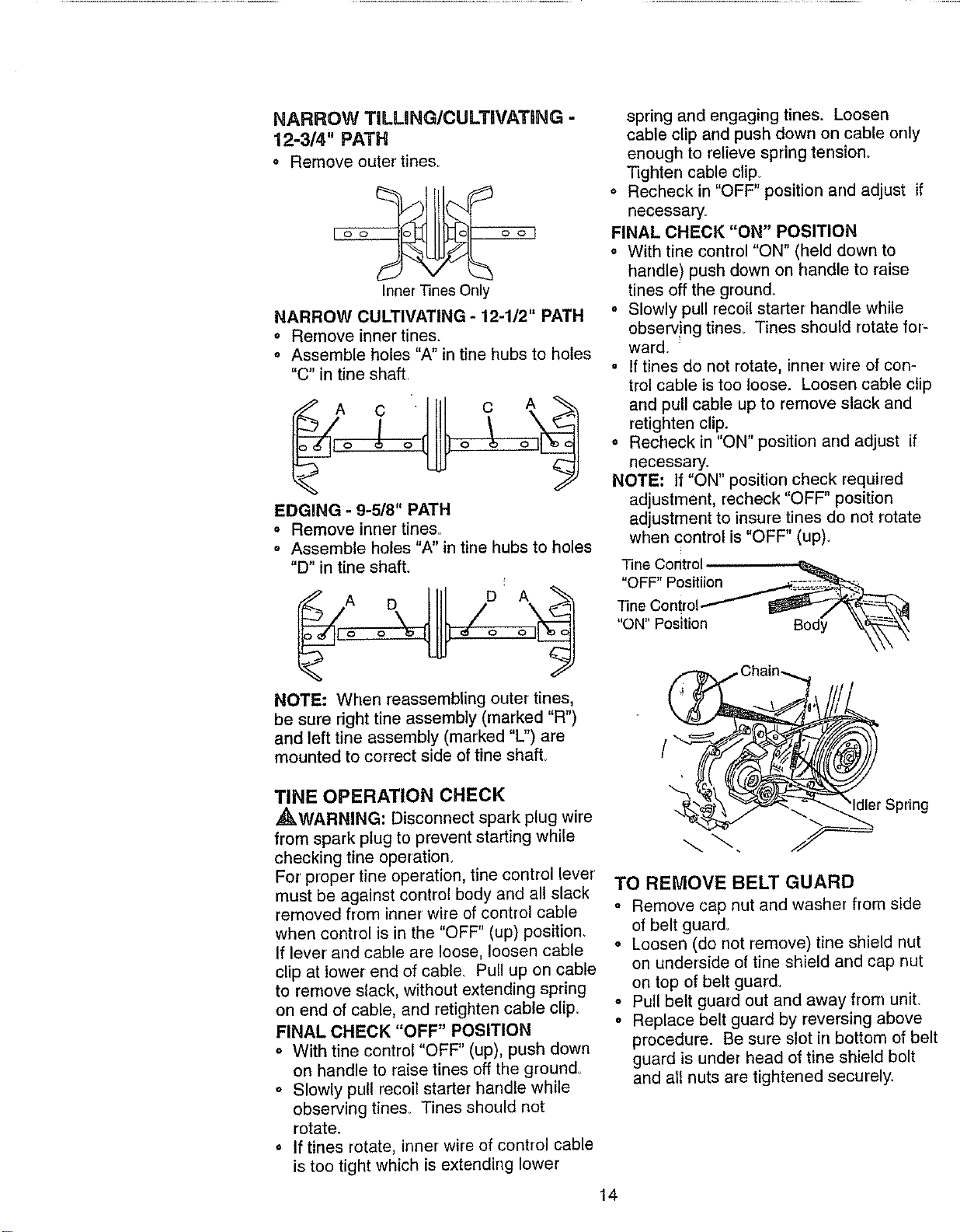
FINAL CHECK "OFF" POSITION
o With tine control "OFF" (up), push down
on handle to raise tines off the ground.
o Slowly pull recoil starter handle while
observing tine& Tines should not
rotate.
° If tines rotate, inner wire of control cable
is too tight which is extending lower
spring and engaging tines. Loosen
cable clip and push down on cable only
enough to relieve spring tension.
Tighten cable clip_
° Recheck in "OFF" position arrd adjust if
necessary.
FINAL CHECK "ON" POSITION
o With fine control "ON" (held down to
handle) push down on handle to raise
tines off the ground_
o Slowly pull recoil starter handle while
observ!ng tine& Tines should rotate for-
ward.
o If tines do not rotate, inner wire of con-
trol cable is too loose. Loosen cable clip
and pull cable up to remove slack and
retighten clip.
o Recheck in "ON" position and adjust if
necessary.
NOTE: If "ON" position check required
adjustment, recheck "OFF" position
adjustment to insure tines do not rotate
when control is "OFF" (up).
OFF' Positiion /_
"fine Oonbol_-_
"ON"Posltion Body _
/
Idler Spring
TO REMOVE BELT GUARD
o Remove cap nut and washer from side
of belt guard_
o Loosen (do not remove) tine shield nut
on underside of tine shield and cap nut
on top of belt guard_
° Pull belt guard out and away from unit.
o Replace belt guard by reversing above
procedure. Be sure slot in bottom of belt
guard is under head of tine shield bolt
and all nuts are tightened securely,
14
CapNutand
Cap_ _er
Oe,t uor -
Nut _- /
TO REPLACE V-BELT
Replace V-belt if it has stretched consider-
ably or if it has cracks or frayed edges.
Belt guard must be removed to service
bell See "TO REMOVE BELT GUARD"
in this section of manual.
BELT REMOVAL
" Remove V-belt from transmission pulley
first and then from engine pulley.
BELT REPLACEMENT
• Install new V-belt to engine pulley first
then to transmission pulley.
Be sure belt is positioned on inside
groove of both pulleys, inside all belt
guides and rests on idler pulley.
CHECK TINE OPERATION
o See "TINE OPERATION CHECK" in this
section of manual
REPLACE BE_ GUARD
Belt
Belt Guide
Bolt
FINAL SETTING
o Start engine and allow to warm for five
minute&
o With throttle control in "SLOW" position_
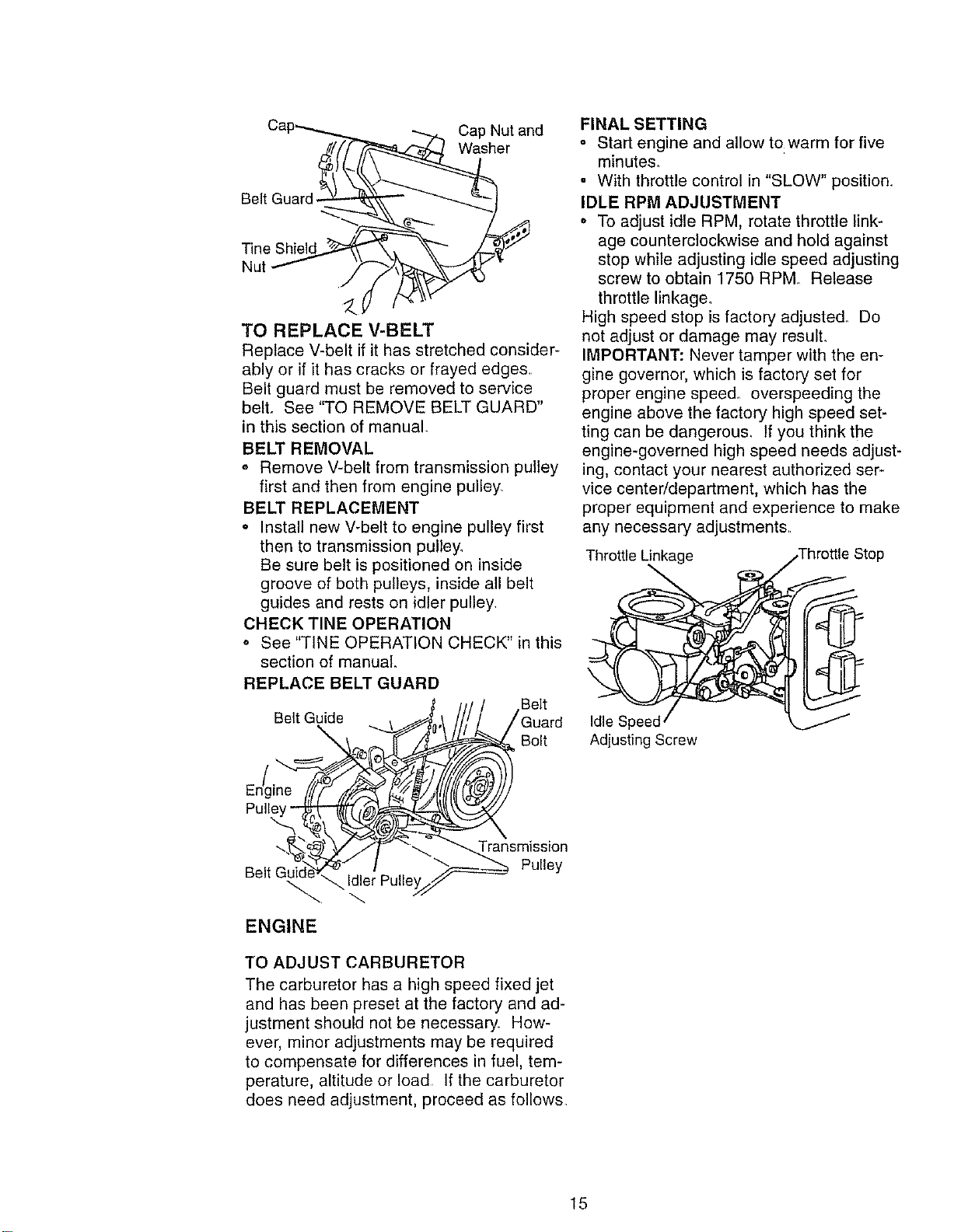
IDLE RPM ADJUSTMENT
• To adjust idle RPM, rotate throttle link-
age counterclockwise and hold against
stop while adjusting idle speed adjusting
screw to obtain 1750 RPM Release
throttle linkage.
High speed stop is factory adjusted. Do
not adjust or damage may resulL
IMPORTANT: Never tamper with the en-
gine governor, which is factory set for
proper engine speed, overspeeding the
engine above the factory high speed set-
ting can be dangerou& If you think the
engine-governed high speed needs adjust-
ing, contact your nearest authorized ser-
vice center/department, which has the
proper equipment and experience to make
any necessary adjustments
Throttle Linkage
Throttle Stop
Idle
Adjusting Screw
Pulle
ENGINE
TO ADJUSTCARBURETOR
The carburetor has a high speed fixed jet
and has been preset at the factory and ad-
justment should not be necessary. How-
ever, minor adjustments may be required
to compensate for differences in fuel, tem-
perature, altitude or load If the carburetor
does need adjustment, proceed as follows.
15
Immediatelyprepareyourtillerforstorage
attheendoftheseasonoriftheunitwill
notbeusedfor30daysormore,,
,_kCAUTION: Never' store the tiller with
gasoline in the tank inside a building
where fumes may reach an open flame or
spark. Allow the engine to cool before
storing in any enclosure,
TILLER
o Clean entire tiller (See "CLEANING" in
the Customer Responsibilities section of
this manual).
o Inspect and replace belts, if necessary
(See belt replacement instructions in the
Service and Adjustments section of this
manual)_
. Lubricate as shown in the Customer
Responsibilities section of this manual.
o Be sure that all nuts, bolts and screws
are securely fastened_ Inspect moving
parts for damage, breakage and wear:,
Replace if necessary.
o ]buch up all rusted or chipped paint sur-
faces; sand lightly before painting,.
ENGINE
FUEL SYSTEM
IMPORTANT: It is important to prevent
gum deposits from forrning in essential fuel
system parts such as the carburetor, fuel
filter, fuel hose, or tank during storage_
also, experience indicates that alcohol
blended fuels (called gasohol or using
ethanol or methanol) can attract moisture
which leads to separation and formation of
acids during storage. Acidic gas can dam-
age the fuel system of an engine while in
storage.
o Drain the fuel tank.
o Start the engine and let it run until the
fuel lines and carburetor are empty=
,, Never use engine or carburetor cleaner
products in the fuel tank or permanent
damage may occur.
o Use fresh fuel next season.
NOTE: Fuel stabilizer is an acceptable
alternative in minimizing the formation of
fuel gum deposits during storage. Add sta-
bilizer to gasoline in fuel tank or storage
container. Always follow the mix ratio
found on stabilizer container: Run engine
at least 10 minutes after adding stabilizer
to allow the stabilizer to reach the carbure-
tor. Do not drain the gas tank and carbu-
retor if using fuel stabilizer.
ENGINE OIL
Drain oil (with engine warm) and replace
with clean oilo (See "ENGINE" in the
Customer Responsibilities section of this
manual)°
CYLINDERS
• Remove spark plug
° Pour 1 ounce (29 ml) of oil through
spark plug hole into cylinder,
. Pull starter handle slowly several times
to distribute oilo
° Replace with new spark plug.
OTHER
o Do not store gasoline from one season
to another:
• ReplaCe your gasoline carl if your can
starts to rust. Rust and/or dirt in your
gasoline will cause problems.
o If possible, stere your unit indoors and
cover it to give protection from dust and
dirt.
o Cover your unit with a suitable protective
cover that does not retain moisture. Do
not use plastic. Plastic cannot breathe
which allows condensation to form and
will cause your unit to rust,
IMPORTANT: Never cover tiller while
engine and exhaust areas are still warm,
I 16
PROBLEM
Will not start
Hard to start
Loss of power
CAUSE
1, OUt of fuel
2 Engine not"CHOKED"
properly
& Engine flooded
4_ Dirty air cleaner
5. Water in fuel
6 Clogged fueltank
7. Loose spark plug wire,
8 Bad spark plug or
improper gap
9 Carburetor out of adjust-
ment
1. Throttle control not set
properly
2 Dirty air cleaner
3 Bad spark plug or
improper gap
4 Stale or dirty fuel
5, Loose spark plug wire,
6 Carburetor out of,
adjustment
1 Engine is overloaded
2, Dirty air cleaner
3 Low oil level/dirty oil
4 Faulty spark plug
5 Oil in fuel
6 Stale or dirty fuel
7, Water in fuel,
8, Clogged fuel tank,
9. Spark plug wire loose
wire,
10. Dirty engine air screen
11, Dirty/clogged muffler,
12 Carburetor out of
adjustment
13 Poor compression
17
CORRECTION
1, Fill fuel tank
2, See "TO START ENGINE" inthe
Operation section
3, Wait several minutes before
attempting to start
4 Clean or replace air cleaner car
tridge
5 Drain fueltank and carburetor,
and refill tank with fresh gasoline
6 Remove fuel tank and clean
7, Make sure spark plug wire is seat
ed properly on plug,
8. Replace spark plug or adjust gap
g_ Make necessary adjustments
1 Place throttle control in "FAST"
position
2_ Clean or replace air cleaner car
tridge.
3 Replace spark plug or adjust gap
4 Drain fuel tank and refill with fresh
gasoline
5 Make sure spark plug wire is seat
ed properly on plug_
6 Make necessary adjustments
1 Set depth stake and wheels for
shallower tilling
2 Clean or replace air cleaner ear
tridge
3 Checkoi! level/change oil,
4 Clean and regap or change spark
plug
5 Drain and clean fuel tank and
refill, and clean carbureton
6 Drain fuel tank and refill with fresh
gasoline,
7, Drain fuel tank and carburetor,
and refill tank with fresh gasoline
8. Remove fuel tank and clean,
9, Connect and tighten spark plug
10 Clean engine air screen
11. Clean/replace muffler,
12 Make necessary adjustments,
13, Contact an authorized Sears
Service CenfedDepartment.
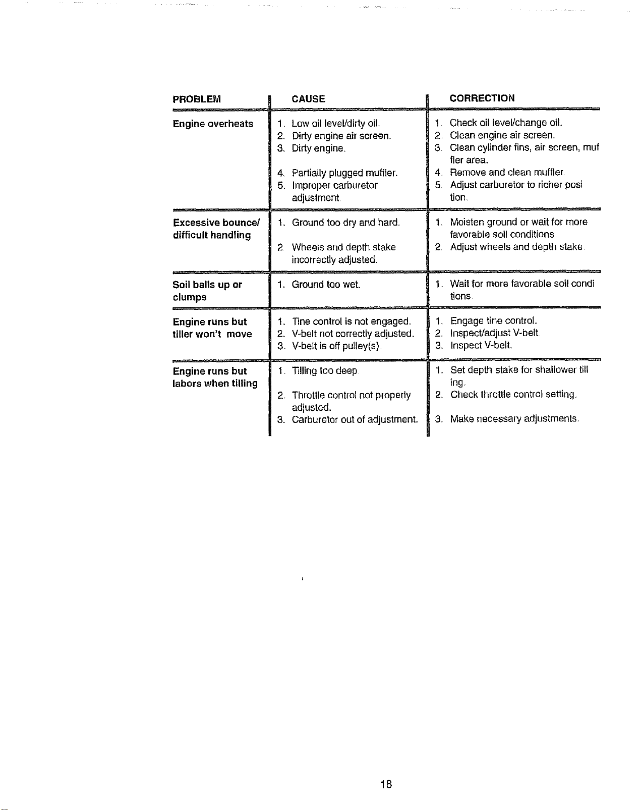
PROBLEM
Engine overheats
Excessive bounce/
difficult handling
Soil balls up or
clumps
Engine runs but
tiller won't move
Engine runs but
labors when tilling
CAUSE
1, Low oil level/dirty oil
2 Dirty engine sir screen,.
3, Dirtyengine
4. Partially plugged muffler.
5. Improper carburetor
adjustment
1. Ground too dry and hard.
2 Wheels and depth stake
incorrectly adjusted.
1, Ground too wet.
1. "i3necontrol isnot engaged.
2. V-belt not correctly adjusted_
3_ V-belt is offpulley(s)
. _t=r
1 Tilling too deep
2_ Throttle control not properly
adjusted_
3_ Carburetor out of adjustmenL
CORRECTION
1. Check oil level/change oil.
2 Clean engine air screen
3. Clean cylinder fins, air screen, muf
tier area.
4. Remove and clean muffler
5 Adjust carburetor to dcher posi
tion
1_ Moisten ground or wait for more
favorable soil conditions
2 Adjust wheels and depth stake
1. Wait for more favorable soil condi
tions
, i_= t........
1, Engage tine control
2 Inspect/adjust V-belt
3_ Inspect V-belL
=,
1. Set depth stake for shallower' till
ing_
2 Check throttle control setting.
3 Make necessary adjustments
18
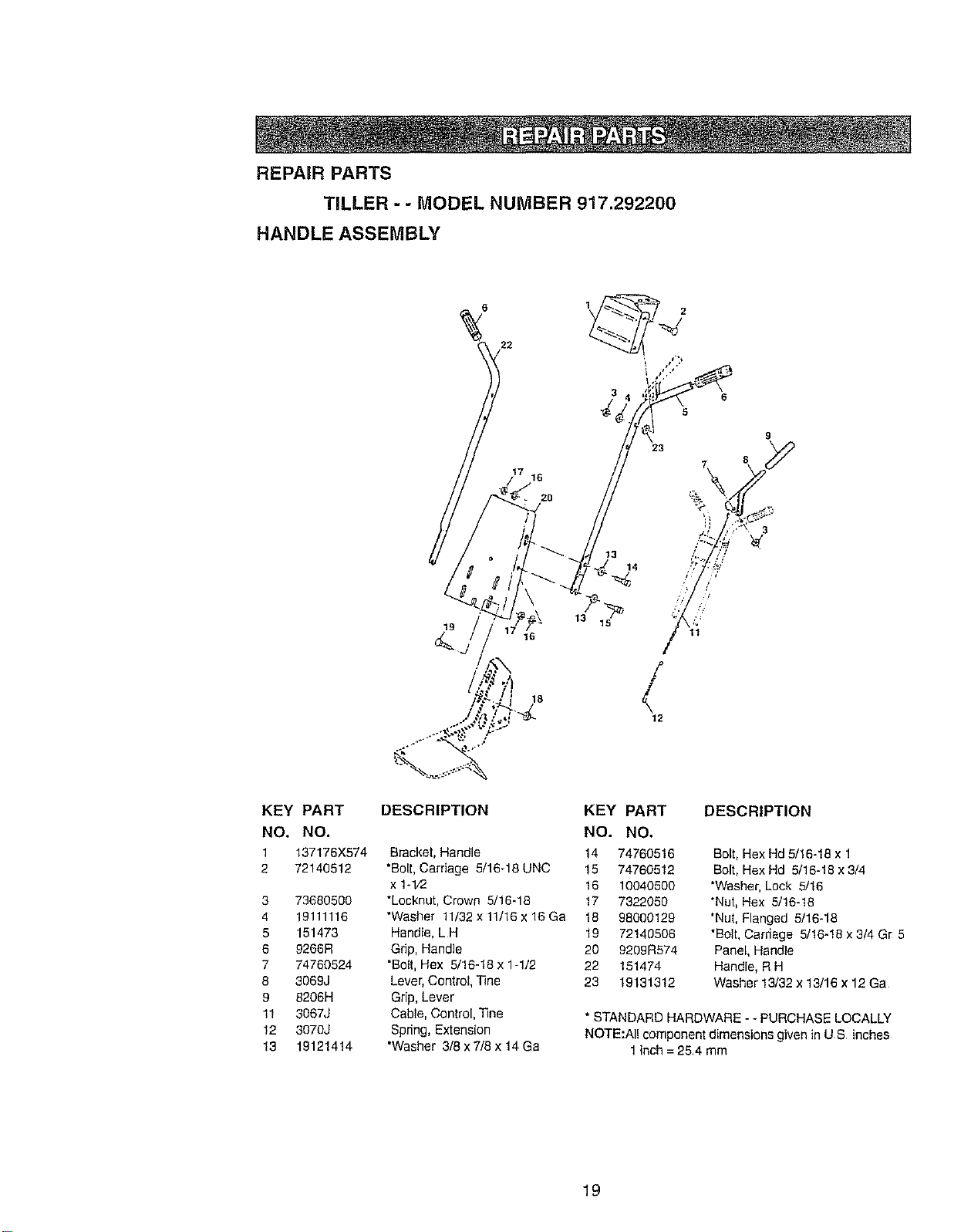
REPAIR PARTS
TILLER - - MODEL NUMBER 917.292200
HANDLE ASSEMBLY
22
16
20
19
18
15
3 6
KEY PART DESCRIPTION KEY PART
NO. NO. NO. NO.
1 137176X574 Bracket, Handle 14 74760516
2 72140512 "Bolt,Carriage 5/16-18 UNC 15 74760512
x 1-l/2 16 10040500
3 73680500 "Lecknut, Crown 5/16-18 17 7322050
4 19111116 "Washer 11/32x 11/16 x 16 Ga 18 98000129
5 151473 Handle, LH 19 72146506
6 9266R Gdp, Handle 20 9209R574
7 74760524 "Bolt,Hex 5/16-18 x 1-1/2 22 151474
8 3069J Lever,Control, T_ne 23 19131312
9 6206H Grip, Lover
11 3067J Cable, Control, 33he
12 3070J Spring, Extension
13 19121414 "Washer 3/8 x 7/8 x 14 Ga
DESCRIPTION
Belt, Hex Hd 5/!6-18 x 1
Bolt, Hex Hd 5/16-18 x 3/4
"Washer, Lock 5/16
*Nut, Hex 5/16-18
"Nut, Flanged 5/16-18
"Bolt,Carriage 5/16-18 x3/4 Gr 5
Panel, Handle
Handle, R H
Washer 13/32 x 13/16 x 12 Ga
* STANDARD HARDWARE - - PURCHASE LOCALLY
NOTE:Al! component dimensions given in US inches
1 inch =254 mm
19
REPAIR PARTS
TILLER - - MODEL NUMBER 917.292200
BELT GUARD AND PULLEY ASSEMBLY
_ 7 9
1
3
KEY PART DESCRIPTION KEY PART
NO. NO. NO. NO.
1 23230506 *Screw,Set, ForgedSocket, 15 132213
Headless 5/16-18 x 3/8 16 12000036
2 130811 Pulley, Engine 17 73350600
3 122965X Bracket Assembly, Guard, Belt 18 161806
4 72140404 *Bolt, Carriage 1/4-20 x 1/2 19 162290
5 74610812 Bolt, Hex 1/2-20 x 3/4 20 74760620
6 121463X Keeper, Belt, Transmission 21 106968X
Pulley 22 105358X
7 104213X Nut, Cap 1/4-20 23 10040400
8 19091016 *Washer 9/32 x 5/8 x 16 Ga. 24 73220400
9 131157X574 Guard, Belt 25 73350500
10 109227X Pad, Idle[
11 72140406 *Bolt, Carriage 1/4-20 x 3/4
12 9179R V-Belt
13 12000028 Ring, Retainer
14 151939 Pufley,Transmission
DESCRIPTION
Bolt,BeltGuard
Ring, Kllp
*Nut, Hex, Jam 3/8-16
Pulley,Idler
Idler Arm Assembly
*Bolt,Hex 3/8-16 x 1-1/4
Shaft, IdlerArm
Shield, Dirt
*Washer Lock 1/4
*Nut, Hex 1/4-20
*Nut,Hex, Jam 5/16-18
*STANDARD HARDWARE--PURCHASE LOCALLY
NOTE:All component dimensionsgiven inUS inches.
1inch = 25_4mm
20
REPAIR PARTS
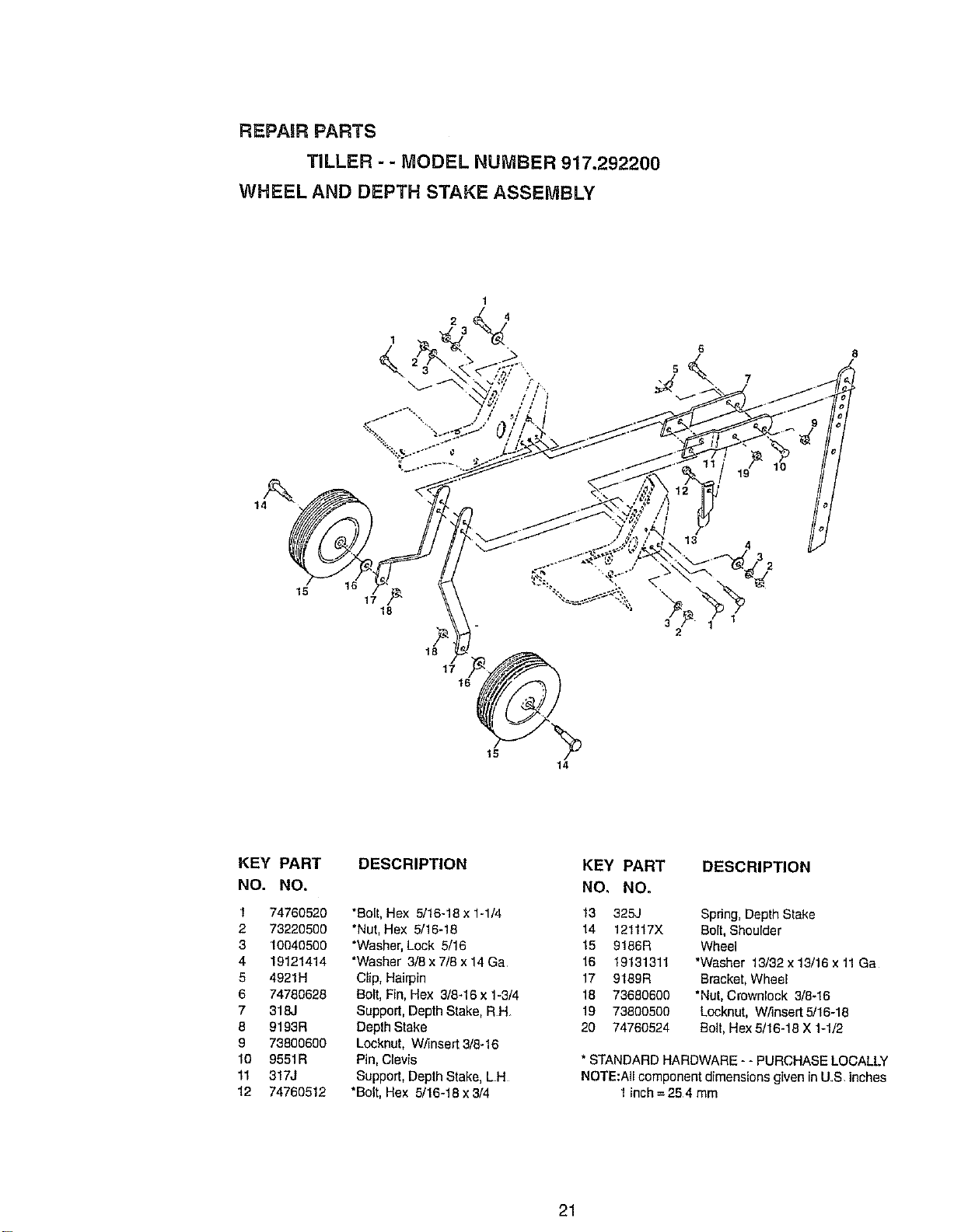
TILLER - - MODEL NUMBER 917.292200
WHEEL AND DEPTH STAKE ASSEMBLY
1
6
S
15
17
18
18
1716__
14
KEY PART
NO. NO.
1 74760520
2 73220500
3 10040500
4 19121414
5 4921H
6 74780628
7 318J
8 9193R
9 73800600
10 9551R
11 317J
12 74760512
DESCRIPTION
*Dolt, Hex 5/16-18 x 1-1/4
*Nut, Hex 5/16-18
*Washer, Lock 5/16
*Washer 3/8 x 7/8 x 14 Ga
Clip, Hairpin
Dolt, Fin, Hex 3/8-16 x 1-3/4
Support, Depth Stake, RH_
Depth Stake
Locknut, Wf_nsert3/8-16
Pin, Clevis
Support, Depth Stake, L H
*Bolt, Hex 5/16-18 x 3/4
KEY PART DESCRIPTION
NO. NO.
13 325J Spring, Depth Stake
14 121117X Bolt, Shoulder
15 9186R Wheel
16 19131311 *Washer 13/32 x 13/16 x 11Ga
17 9189R Dracket, Wheel
18 73680600 *Nut, Crownlock 3/8.16
19 73800500 Locknut, W/'lnsert5/16-18
20 74760524 Dolt,Hex 5/16-18 X 1-1/2
* STANDARD HARDWARE -- PURCHASE LOCALLY
NOTE:All component dimensions given in US inches
1 inch= 254 mm
21
REPAIR PARTS
TILLER - - MODEL NUMBER 917,292200
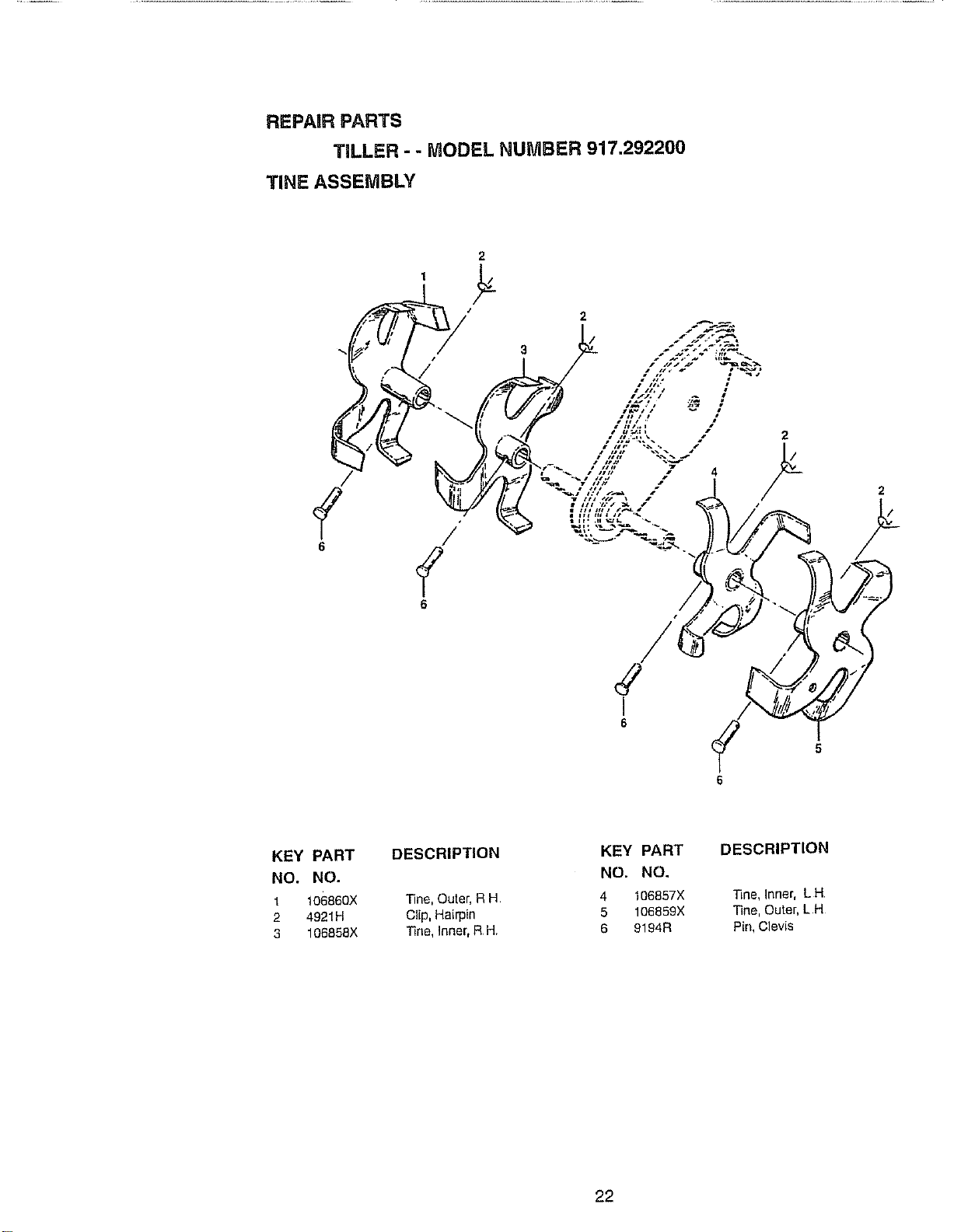
TINE ASSEMBLY
6
2
5
6
KEY PART
NO. NO.
1 106860X
2 4921H
3 106858X
DESCRIPTION
Tine, Outer, R H
Clip, Hairpin
line, Inner, RH
KEY PART DESCRIPTION
NO. NO.
4 106857X Tine, Inner, L H
5 106859X Tine, Outer, L H
6 9194R Pin, Clevis
22
REPAIR PARTS
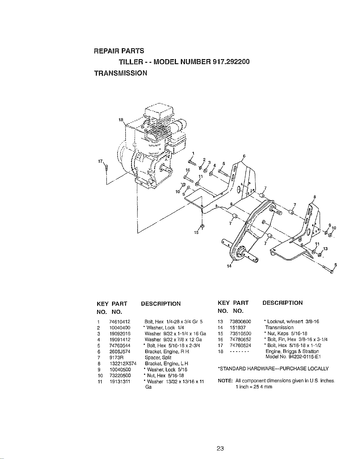
TILLER - - MODEL NUMBER 917.292200
TRANSMISSION
7
11
13
14
KEY PART
NO. NO,
1 74610412
2 10040400
3 19092016
4 19091412
5 74760544
6 2606J674
7 9173R
8 !32212X574
9 10040500
10 73220500
11 19131311
DESCRIPTION
Bolt, Hex 1/4-28 x 3/4 Gr 5
• Washer, Lock 1/4
Washer 9/32 x 1-1/4 x 16 Ga
Washer 9/32 x 7/8 x 12 Ga
" Bolt, Hex 5/16-18 x 2.314
Bracket, Engine, R H
Spacer,Split
Bracket, Engine, LH
* Washer, Lock 5/16
• Nut, Hex 5/16-18
* Washer 13/32 x 13/16 x 11
Ga
KEY PART
NO. NO.
13 738OO6OO
14 151937
15 73510500
16 74780652
17 74760524
18 .......
DESCRIPTION
• Locknut, w/insert 3/8-16
Transmission
* Nut, Keps 5/16-18
• Bolt, Fin, Hex 3/8-16 x 3-1/4
* Bolt, Hex 5/16-18 x 1-1/2
Engine, Briggs & Stratton
Model No 94202-0115-E1
*STANDARD HARDWARE--PURCHASE LOCALLY
NOTE: All component dimensions given inU S inches
1inch = 25 4 mm
23
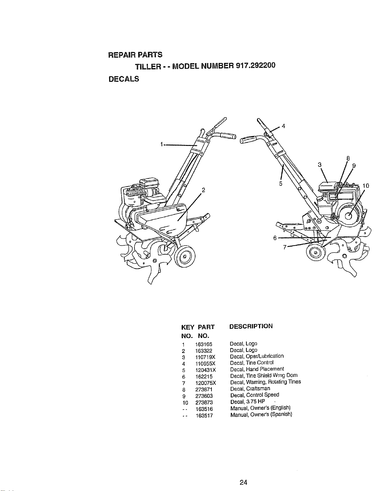
REPAIR PARTS
TiLLER--MODEL NUMBER 917.292200
DECALS
1-
% 2
8
KEY PART
NO. NO.
1 163165
2 163322
3 110719X
4 118655X
5 120431X
6 162215
7 120075X
8 273871
9 273603
10 273873
-- 163516
-- 163517
DESCRIPTION
Decal, Logo
Decal, Logo
Decal, Oper/Lubrication
Decal, Tine Control
Decal, Hand Placement
Decal, ]]ne Shield Wrng Dorn
Decal, Warning, Rotating ]qnes
Decal, Craftsman
Decal, Control Speed
Decal, 3.75 HP
Manual, Owner's (English)
Manual, Owner's (Spanish)
24
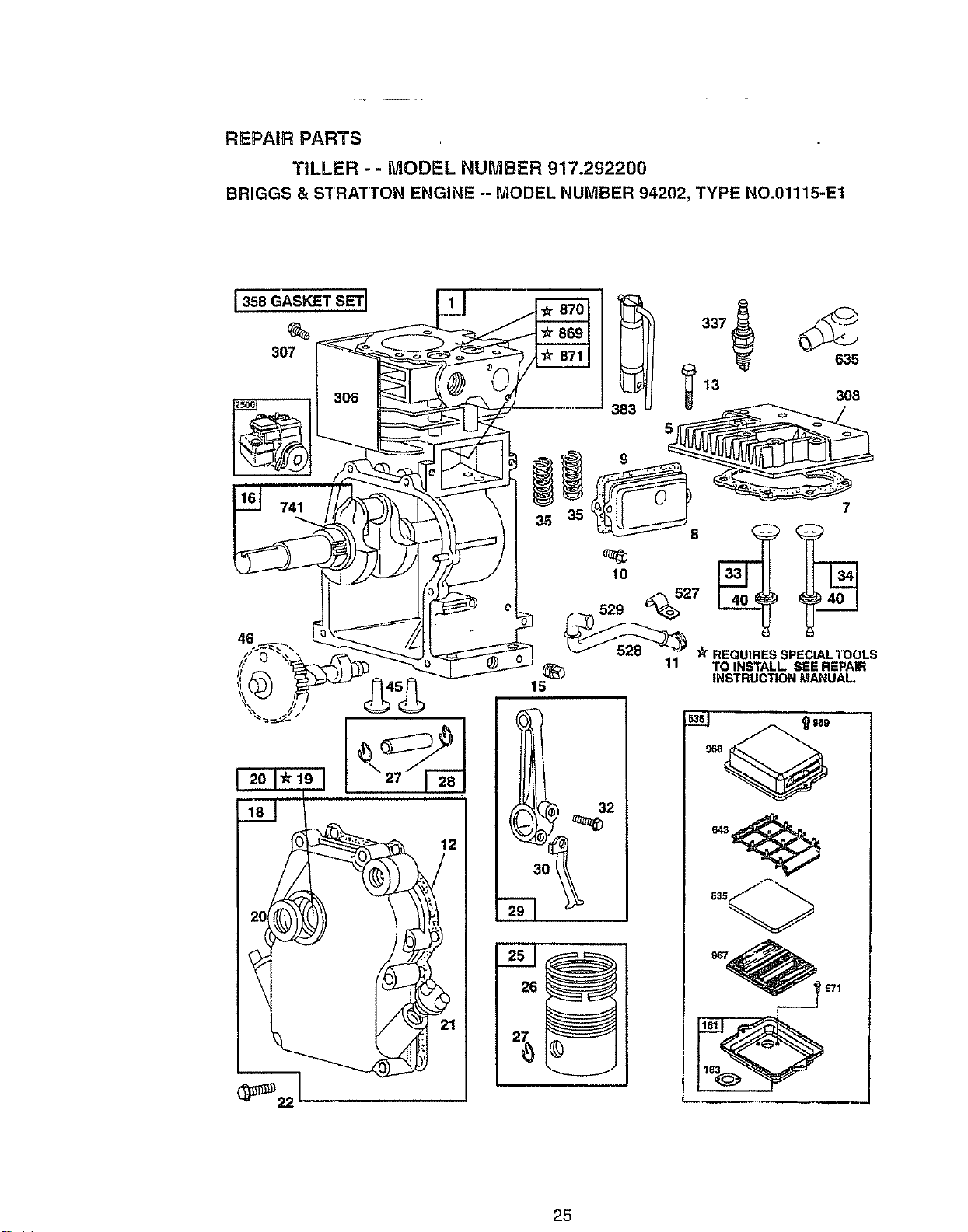
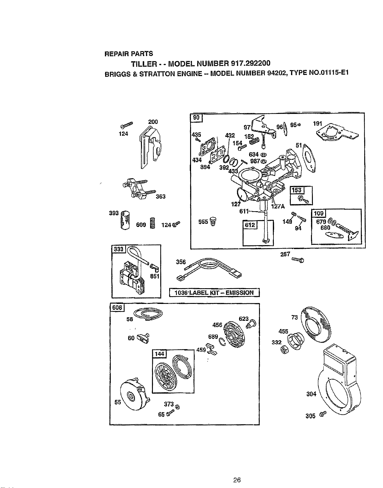
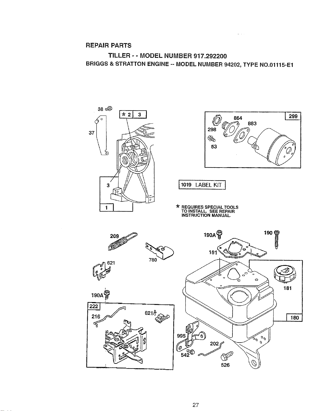
REPAIR PARTS
TILLER - - MODEL NUMBER 917.292200
BRIGGS & STRATTON ENGINE -- MODEL NUMBER 94202, TYPE NO,01115-E1
635
13 308
INSTRUCTION MANUAL
15
32
26
25
REPAIR PARTS
TILLER - - MODEL NUMBER 917.292200
BRIGGS & STRATTON ENGINE -- MODEL NUMBER 94202, TYPE NO.O1115-E1
200
124
_363
393
609 124_
851
H
58_
60
373
6s_
455
33
• L_
304
305 _P
26
REPAnRPARTS
TILLER - - MODEL NUMBER 917.292200
BRIGGS & STRATTON ENGINE -- MODEL NUMBER 94202, TYPE NO.01115-E1
8,4
53
1019 LABEL KIT ]
REQUIRES SPECIALTOOLS
TO INSTALL. SEE REPAIR
INSTRUCTION MANUAL
883
181
190A_
27
REPAIR PARTS
TILLER - - MODEL NUMBER 917.292200
BRIGGS & STRATTON ENGINE -- MODEL NUMBER 94202, TYPE NO.01115-E1
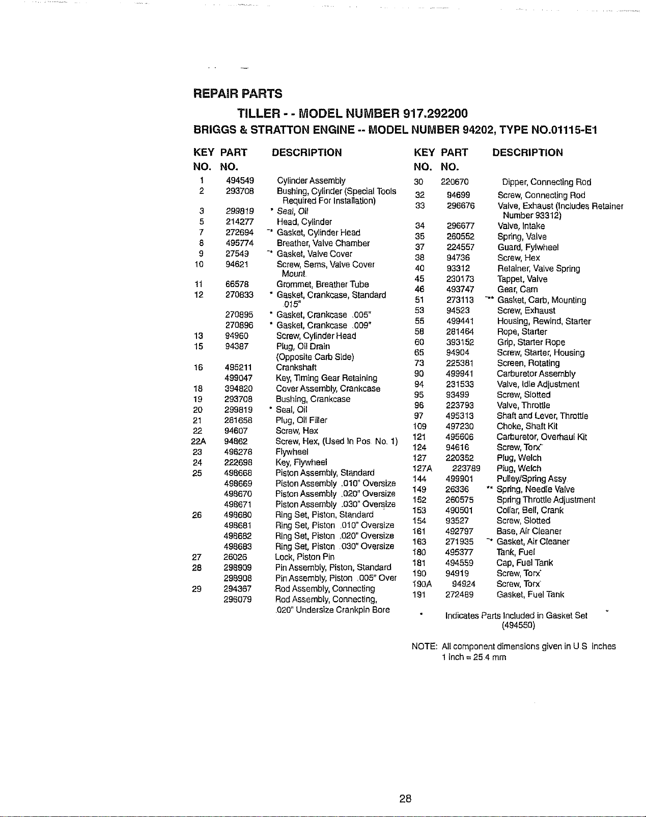
KEY PART DESCRIPTION KEY PART
NO. NO. NO. NO.
1 494549 Cylinder Assembly 30 220670
2 293708 Bushing, Cylrhder (Special Tools 32 94699
Required ForInstallation) 33 296676
3 299819 " Seal, Oi_
5 214277 Head,Cylinder 34 296677
7 272694 -" Gasket, Cylinder Head 35 260552
8 495774 Breather, Valve Chamber 37 224557
9 27549 _' Gasket, Valve Cover 38 94736
10 94621 Screw,Seres, Valve Cover 40 93312
Mount
45 230173
!1 66578 Grommet, Breather Tube 46 493747
12 270833 " Gasket, Crankcase, Standard
015" 51 273113
270895 " Gasket, Crankcase .005" 53 94523
270896 * Gasket, Crankcase .009" 55 499441
13 94960 Screw, Cylinder Head 58 281464
60 393152
15 94387 Plug, Oil Drain 65 94904
(Opposite Carb Side) 73 225381
16 495211 Crankshaft
499047 Kay,Timing Gear Retaining 90 499941
18 394820 CoverAssembly, Crankcase 94 231533
19 293708 Bushing, Crankcase 95 93499
20 299819 * Seal, Oil 96 223793
21 281658 Plug,Oil Filler 97 495313
109 497230
22 94607 Screw,Hex
22.A 94862 Screw, Hex, (Used tn Pos No. 1) 121 495606
23 496278 Flywheel 124 94616
127 220352
24 222698 Key, Flywheel 127A 223789
25 498668 PistonAssembly, Standard 144 499901
498669 PistanAssembly ,010" Oversize
498670 PistonAssembly .020" Oversize 149 26336
162 260575
498671 PistonAssembly .030" Oversize 153 490501
26 498680 Ring Set, Piston, Standard 154 93527
496681 Ring Set, Piston 010" Oversize
496682 Ring Set, Piston .020" Oversize 161 492797
498683 Ring Set, Piston 030" Oversize 163 271935
180 495377
27 26026 Lock, Piston Pin 181 494559
28 298909 PinAssembly, Piston, Standard 190 94919
298908 PinAssembly, Piston 005" Over 190A 94924
29 294367 RodAssembly, Connecting 191 272489
296079 RodAssembly, Connecting,
.020"Undersize Crankpin Bore
DESCRIPTION
Dipper, Connecting Rod
Screw,Connecting Rod
Valve, Exhaust (Includes Retainer
Number 93312)
Valve, Intake
Spring,Valve
Guard, Fylwheel
Screw, Hex
Retainer,Valve Spring
Tappet, Valve
Gear, Cam
"*" Gasket, Carb, Mounting
Screw, Exhaust
Housing, Rewind, Starter
Rope, Starter
Gdp, Starter Rope
Screw, Starter, Housing
Screen, Rotating
Carburetar Assembly
Valve, IdleAdjustment
Screw, SIottad
Valve, Throttle
Shaft and Lever, Throttle
Choke, Shaft Kit
Ca_uretor, Overhaul Kit
Screw,Torx"
Plug, Welch
Rug, Welch
PuUey/SpdngAssy
"" Spdng, Needle Valve
Spring Throttle Adjustment
Collar, Bell, Crank
Screw,Slotted
Base,Air Cleaner
-* Gasket,Air Cleaner
Tank, Fuel
Cap, Fuel Tank
Screw,Torx"
Screw,Torx'
Gasket, Fuel Tank
Indicates Parts Included in Gasket Set
(494550)
NOTE: All component dimensions given in U S inches
1 inch= 25 4 mm
28
REPAIR PARTS
TILLER - - MODEL NUMBER 917.292200
BRIGGS & STRATTON ENGINE -- MODEL NUMBER 94202, TYPE NO.01115-E1
KEY PART
NO. NO.
200 495213
201 263174
202 262470
209 260041
216 263188
222 499533
257 93543
298 220859
300 493288
304 499522
305 94786
386 224555
307 93758
309 224556
332 94877
333 496914
334 94731
337 802592
356 497296
358 495605
363 192o3
373 94908
383 69838
392 262328
393 225058
394 272538
432 221377
433 93265
434 213963
435 93141
455 225502
456 281503
459 281505
526 94914
527 223786
526 491435
529 67838
535 491435
536 494279
542 94897
608 499706
DESCRIPTION
KEY PART DESCRIPTION
NO. NO,
Blade, Governor 609 265715 Spring, Choke
Link, Governor 611 231067 Line, Fuel
Link, Throttle 612 391813 Tube, Pickup
Spdng, Governor 614 93306 Pin, Cotter
Link, Choke 616 496818 Crank, Governor
Bracket, Control 618 262803 ** Spdng
Screw, Hex Head 621 296110 Switch, Stop
Locknut,Muffler 621A 396847 Switch, Stop
Muffler, Exhaust 623 94943 Screw, Shoulder
Housing, Blower 634 271853 Washer, Throff]e Shaft, Foam
Screw, Seres 635 66538 Elbow, Spark Plug
Shield, Cylinder 643 280737 Spacer,Air Cleaner
Screw, Seres, Cylinder Shield 679 270382 Washer, Choke Shaft, Foam
Mnt 680 221839 Washer, Choke Shaft
Cover, Cylinder Head 699 263073 Spdng, Friction
Nut, Flywheel 741 261533 Gear, Timing
Armature, Magneto 760 225029 Anchor, Spring
Screw,Armature Mounting 851 493880 Terminal, Ignition Cable
Plug, Spark 864 492232 Adapter Assembly, Muffler
Wire, Ground 889 211172 Seat, Intake Valve
Gasket Set 870 211291 Seat, Exhaust Valve
Puller, Flywheel 871 231348 Guide, Exhaust Valve
Nat, Hex 63709 Guide, intakeValve
Wrench, Spark Plag (See RepairManual)
Spring, Fuel Pump Diaphragm 883 272203 Gasket, Muffler
Screw, Carburetor 955 281227 Plug
** Diaphragm 967 491588 Filter,Air
Cap, Spdng 968 495872 Cover,Air Cleaner
Pin, Diaphragm 969 490073 Screw, Slotted Hex,
Cover, Diaphragm (Incl Grommet)
Screw, Diaphragm Cover 971 94902 Screw, Hex
Cup, Flywheel 997 398970 Seal,Throttle Shaft
Plate, Pawl Friction 995 497195 Control, Throttle
Pawl, Ratchet 1036 499329 Label Kit, Emission
Screw, Hex 2500 94202-0115 Replacement Engine
Clamp, Breather Tube 495914 Replacement Shottblock
Filter,Air
Grommet, Breather Tube RPM Settings: Low: 1200 - 1600
Fiffer,Air High: 3500 -3700
Air Cleaner Kit
Screw, Hex Head Indicates Parts Included in Gasket Set (494550)
Starter Assembly, Rewind
NOTE: All component dimensions given in U S inches
1inch = 254 mm
29

30

=ortherepair or replacement parts you need
:lelivered directly to your home
3all 7 am - 7 pm, 7 days a week
1-800=366-PART
I1-800-366-7278)
Para ordenar piezas con entrega a
domicilio - 1-800-659-7084
For in-house major brand repair service
3all 24 hours a day, 7 days a week
1=800=4-REPAIR
(1-800-473-7274)
Para pedir servicio de reparacibn a
domicilio - 1-800-676.5811
For the location of a Sears Parts and
Repair Center in your area
Call 24 hours a day, 7 days a week
1=800=488-1222
For information or] purchasing a Sears
Maintenance Agreement or to inquire
about an existing Agreement
Call 9 am - 5 pm, Monday-Saturday
1-800-827-6655
When requesting service or ordering
parts, always provide the following
information:
=Product Type o Part Number
• Model Number = Part Description
America s Repair Specza/Jsts
163516 Rev. 3 1.13.98TR Printed in UoS.A,