Loading ...
Loading ...
Loading ...
j Installation Instructions Split System Condensers J
Installing Refrigerant Lines
Component Matches
Check to see that you have the proper system compo-
nents. APPROVED MATCHED SYSTEM COMPON ENTS
MUST BE USED. Refer to the Sales Specification Sheet
or Split System Summary for match data and orifice
sizes,
The outdoor units are shipped with a refrigerant charge to
match the indoor unit and 15 ft. (4.5m) of refrigerant line. If
shorter or longer lines are used, the charge will have to be
adjusted.
TOTAL LENGTH OF REFRIGERANT LINES MUST NOT
EXCEED 50 ft. WITH A MAXIMUM VERTICAL SEPARA-
TION OF 40 ft. BETWEEN THE OUTDOOR AND IN-
DOOR UNITS.
PLEASE! UNDER NO CIRCUMSTANCES LEAVE THE
LINES OPEN TO THE ATMOSPHERE FOR ANY
PERIOD OF TIME,
Be extra careful with sharp bends. This tubing can "kink"
very easily, and if this occurs, the entire tube length will
have to be replaced. Extra care at this time will eliminate
future service problems.
Suspension And Installation Of
Refrigeration Lines
DO NOT fasten liquid or suction lines in direct contact with
the floor or ceiling joist. Use an insulated or suspension
type of hanger. Keep both lines separate, and insulate the
suction line. Both lines should be insulated in long runs in
an attic or underground in a raceway.
Restrictor Orifice
Some indoor matches use a restrictor orifice in the fitting at
the indoor coil. Some matches may require a different ori-
fice for proper system performance and it must be changed
before the refrigerant lines are connected.
Changing the Restrictor Orifice
The restrictor orifice is located in a fitting in the liquid line.
The fitting is actually the distributor end of the cap tube as-
sembly.
1. Remove the liquid line fitting and replace restrictor ori-
fice. (STANDARD RIGHT HAND THREAD)
2. Make sure the restrictor is installed with the rounded
end toward the feeder tubes. See Figure 3.
Figure 3 J
Restrictor Orifice
Nut and Liquid Line
with Strainer
! RRestr 'dC_drEOd''ce
_Feeder Tubes
Refrigeration Line Sets
Ifit is necessary toadd tubing in the field, use dehydrated or
dry sealed deoxidized copper refrigeration tube. DO NOT
use copper water pipe.
It is important that no tubing iscut or seals broken until
you are ready to actually make connections to the
evaporator and to the condenser section.
Do not remove rubber plugs or copper caps from the
tube ends until ready to make connections at evapora-
tor and condenser.
Do not let refrigerant lines come in direct contact with
foundation. When running refrigerant lines through the
foundation or wall, the openings should be made large
enough to allow for a sound absorbing material to be
placed or installed between the tubing and the foundation.
This will prevent noise transmission between the tubing
and the wall section (foundation) or the building.
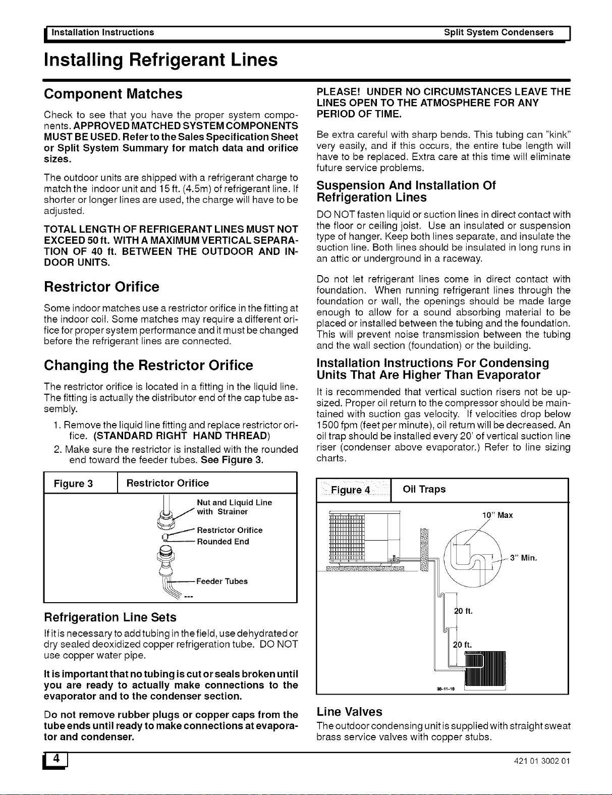
Installation Instructions For Condensing
Units That Are Higher Than Evaporator
It is recommended that vertical suction risers not be up-
sized. Proper oil return to the compressor should be main-
tained with suction gas velocity. If velocities drop below
1500 fpm (feet per minute), oil return will be decreased. An
oil trap should be installed every 20' of vertical suction line
riser (condenser above evaporator.) Refer to line sizing
charts.
Figure 4 Oil Traps
10" Max
Min.
_8-11-1e
Line Valves
The outdoor condensing unit issupplied with straight sweat
brass service valves with copper stubs.
_J 421 01 3002 01
Loading ...
Loading ...
Loading ...