
Loading ...
Loading ...
Loading ...
11
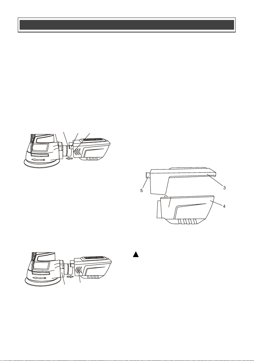
INSTALLING THE DUST BOX ASSEMBLY
1. Insert the dust duct box assembly sleeve
(1) onto the dust chute (2) (Fig. 1).
NOTE: Make sure the locking tabs (3)
insert into the matching slots (4) in the rear
of the sander housing.
2. Push the dust box assembly sleeve fully
onto the dust chute until the locking tabs
“snap” into place to hold the dust box firmly
onto the sander.
NOTE: Remove and clean the dust box
assembly periodically to remove
accumulated dust from the dust box.
CLEANING THE DUST BOX
The dust box will collect much of the sanding
dust that is generated during sanding
operations. As a result, it must be cleaned out
periodically so the dust collection will be
efficient.
1. Squeeze the sides of the dust box (1) and
pull it away from the rear of the sander (2)
(Fig. 2).
2. Pry the top of the dust box (3) away from
the bottom of the dust box (4) (Fig. 3).
NOTE: It is best to perform this function
either outside or over a trash can, as loose
dust will come out of the dust box very
easily.
3. Shake all the dust out of the dust box.
4. Use a soft DRY brush to remove the dust
from the filter located inside the top of the
dust box.
5. Once all the sanding dust is removed from
the dust box, press the upper and lower
sections together. They will “snap” into
place when properly assembled.
6. Reinstall the dust box onto the rear of the
sander.
NOTE: The locking tabs (5) will “snap” into
place when the dust box is fully pushed
onto the rear of the sander.
INSTALLING A SANDING DISC
WARNING: Unplug the sander from the
power source before installing or changing
the sanding disc.
To install a sanding disc, firmly press the
sanding disc (1) onto the hook & loop pad (2)
(Fig. 4).
NOTES:
a) Place the sanding disc so the holes in the
disc line up with the matching holes in the hook
& loop pad.
b) Press the sanding disc firmly onto the hook &
loop pad.
ASSEMBLY AND OPERATING
!
Fig. 3
Fig. 1
4
2
1
3
Fig. 2
2
1
Loading ...
Loading ...
Loading ...