Loading ...
Loading ...
Loading ...
7
Installation Requirements
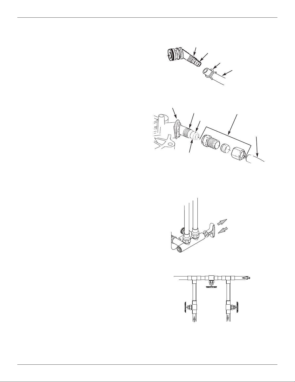
VALVE DRAIN REQUIREMENTS
Using the flexible drain hose (included), measure and
cut to the length needed. Flexible drain hose is not
allowed in all localities (check your plumbing codes). If
local codes do not allow use of a flexible drain hose, a
rigid valve drain run must be used. Purchase a com-
pression fitting (1/4 NPT x 1/2 in. minimum tube) and
1/2" tubing from your local hardware store. Plumb a
rigid drain as needed (See Figure 6).
NOTE: Avoid drain hose runs longer than 30 feet.
Avoid elevating the hose more than 8 feet
above the floor. Make the valve drain line as
short and direct as possible.
INLET / OUTLET PLUMBING OPTIONS
Always install either a single bypass valve (provided),
as shown in Figure 7, or, if desired, parts for a 3 valve
bypass system (not included) can be purchased and
assembled, as shown in Figure 8. Bypass valves
allow you to turn off water to the softener for mainte-
nance if needed, but still have water in house pipes.
Use:
= Copper pipe
= Threaded pipe
= PEX (Crosslinked Polyethylene) pipe
= CPVC plastic pipe
= Other pipe approved for use with potable water
IMPORTANT: Do not solder with plumbing attached to
the single bypass valve. Soldering heat
will damage the plastic valve.
FIG. 6
Clip
Barbs
1/4 NPT
Threads
1/2” Outside Dia.
Copper Tube
(not included)
Compression Fitting.
1/4 NPT x 1/2” O.D.
Tube (not included)
Cut barbs from drain fit-
ting (pull clip to remove
fitting from valve)
FIG. 7
FIG. 8
SINGLE BYPASS VALVE
Pull out for “Service”
(Soft water)
Push in for
“Bypass”
3 VALVE BYPASS
From Water
Softener
To Water
Softener
Inlet
Valve
Outlet
Valve
Bypass
Valve
FIG. 5
1/4” NPT
Thread
Barbs for 3/8”
I.D. Tubing
Drain Hose
Hose Clamp
Loading ...
Loading ...
Loading ...