McIntosh Laboratory, Inc. 2 Chambers Street Binghamton, New York 13903-2699 Phone: 607-723-3512 www.mcintoshlabs.com
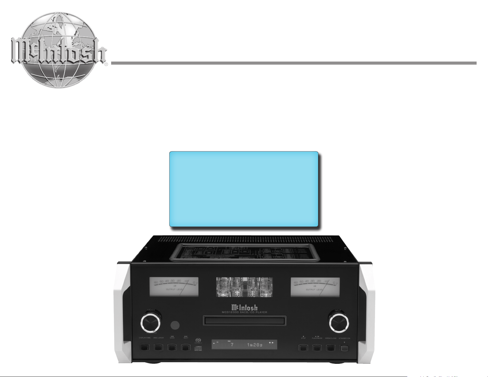
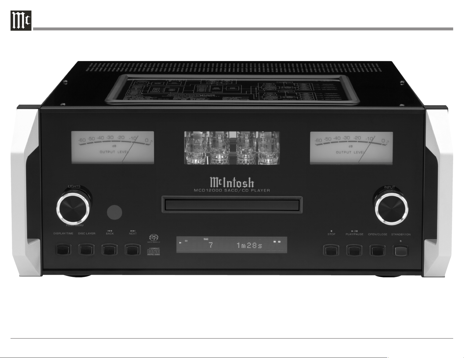
MCD12000
SACD/CD Player
Owner's Manual
2
The lightning ash with arrowhead, within an equilateral
triangle, is intended to alert the user to the presence of
uninsulated “dangerous voltage” within the product’s en-
closure that may be of sucient magnitude to constitute
a risk of electric shock to persons.
The exclamation point within an equilateral triangle is
intended to alert the user to the presence of important
operating and maintenance (servicing) instructions in the
literature accompanying the appliance.
WARNING - TO REDUCE RISK
OF FIRE OR ELECTRICAL
SHOCK, DO NOT EXPOSE
THIS EQUIPMENT TO RAIN OR
MOISTURE.
NO USER-SERVICEABLE PARTS
INSIDE. REFER SERVICING TO
QUALIFIED PERSONNEL.
To prevent the risk of electric
shock, do not remove cover or
back. No user-serviceable parts
inside.
ATTENTION:
RISQUE DE CHOC ELECTRIQUE - NE PAS OUVRIR
Additional Safety Information is supplied in a separate document “Important Additional Operation Information Guide”
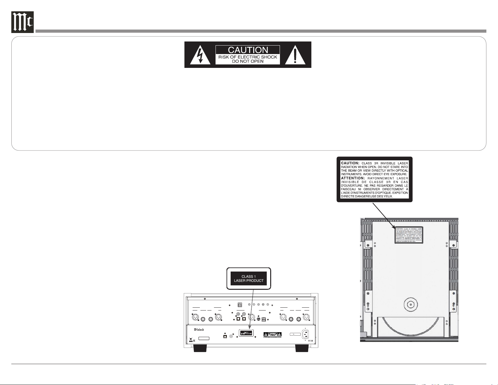
CAUTION: Invisible Laser Radiation when
open. DO NOT stare into the
beam or view directly with opti-
cal instruments. Use of controls
or adjustments or performance
of procedures other than those
specified in the Owners Manual
may result in Hazardous Radiation
Exposure.
ATTENTION: Rayonnnement Laser Invisible en
cas d’ouverture. Ne pas regarder
dans le faisceau ni observer di-
rectement à l’aide d’instruments
d’optiques. L’utilisation de
commandes, de réglages ou
d’instructions autres que ceux
spécifiés dans le manuel du
propriétaire peut entraîner une
exposition x à des rayonnements
dangereux
LUOKAN 1 LASERLAITE
KLASS 1 LASER APPARAT
VAROITUS! Laitteen kayttaminen muulla kuin tassa
kayttoohjeessa mainitulla tavalla saat-
taa altistaa kayttajan turvallisuusluokan
1 ylittavalle nakymattomalle lasersate-
iiylle.
VARNING! Om apparaten anvands pa annat satt an i
denna bruksanvisning specificerats, kan
anvandaren utsattas for osynbg laser-
straining, som overskrider gransen for
laserklass 1.
This product incorporates an embedded
CLASS 3R Laser (IEC60825-1).
Interior view
/
120V 50 60Hz 50W
COAXIAL
OPTICAL
DIGITAL
AUDIO OUTPUTS
SERIAL
NUMBER
HANDCRAFTED IN USA WITH US AND IMPORTED PARTS
McINTOSH LABORATORY, INC.,
BINGHAMTON, NY
SAC D/C D PLAYE R
MCD 12000
CLASS 1
LASER PRODUCT
Product complies with CRF Title 21, Ch. 1,
Subchapter ‘J’, Sections 1010.2, 1010.3, 1040.10
and 1040.11, in effect at date of manufacture.
CAUTION
RISK OF ELECTRIC SHOCK
DO NOT OPEN
UNBALANCEDBALANCED UNBALANCED
BALANCED
RIGHT AUDIO OUTPUTS
BALANCED
UNBALANCED BALANCEDUNBALANCED
LEFT AUDIO OUTPUTS
SERVICE
DATA IN OUT IN
POWER
CONTROL
DIGITAL AUDIO INPUTS
MCT
AES/EBU
IR INRS232
TUBE SOLID STATE
TUBESOLID STATE
COAX 1
OPTICAL 1
COAX 2
OPTICAL 2
USB
3
Thank you from all of us at McIntosh
With the MCD12000 SACD/CD Player, you have
invested in a precision instrument that will provide
you with many years of enjoyment. Please take a few
moments to familiarize yourself with the features and
instructions to get the maximum performance from
your equipment.
If you need further technical assistance, please contact
your dealer who may be more familiar with your
particular setup including other brands. You can also
contact McIntosh with additional questions or in the
unlikely event of needing service.
McIntosh Laboratory, Inc.
2 Chambers Street
Binghamton, New York 13903
Technical Assistance: (607) 723-3512
Customer Service: (607) 723-3515
Fax: (607) 724-0549
Email: [email protected]
Website: mcintoshlabs.com
Make a Note
For future reference, you can jot down your serial
number and purchase information here. We can
identify your purchase from this information if the
occasion should arise.
Serial Number:
Purchase Date:
Dealer Name
Introduction
The MCD12000 is McIntosh’s flagship SACD/
CD Player combining an award-winning history of
vacuum tube innovation with cutting edge digital
technology including the state-of-the-art profes-
sional series ESS Digital-to-Analog converter. The
MCD12000 provides an unsurpassed sonic experience.
• Octal Balanced Low Distortion 32-bit PCM/
DSD
• 8 DACs per channel
• Tube Balanced and Unbalanced Audio Outputs
(as well as Solid State)
• 32Bit/384kHz Up-Sampling
Copyright 2022 © by McIntosh Laboratory, Inc
Table of Contents
Introduction ............................................................... 3
Trademark and License Information ........................ 3
Dimensions ............................................................... 4
Where to Put It .......................................................... 4
Navigating the Rear Panel ........................................ 5
Connection Diagram ................................................. 6
Navigating the Front Panel ........................................ 7
Navigating the Display.............................................. 8
Connector and Cable Information ............................ 9
Using the Setup Menu ............................................... 10
Playing/Navigating a Disc ........................................ 11
Using Remote for MP3/WAV, Data Playback ........... 12
Resetting the Microprocessor .................................. 13
Navigating the Remote Control ................................ 14
Changing Remote Control Batteries ......................... 15
Audio Specifications ................................................ 18
Digital Audio Specifications ..................................... 18
General Specifications .............................................. 18
Packing the MCD12000 ............................................ 19
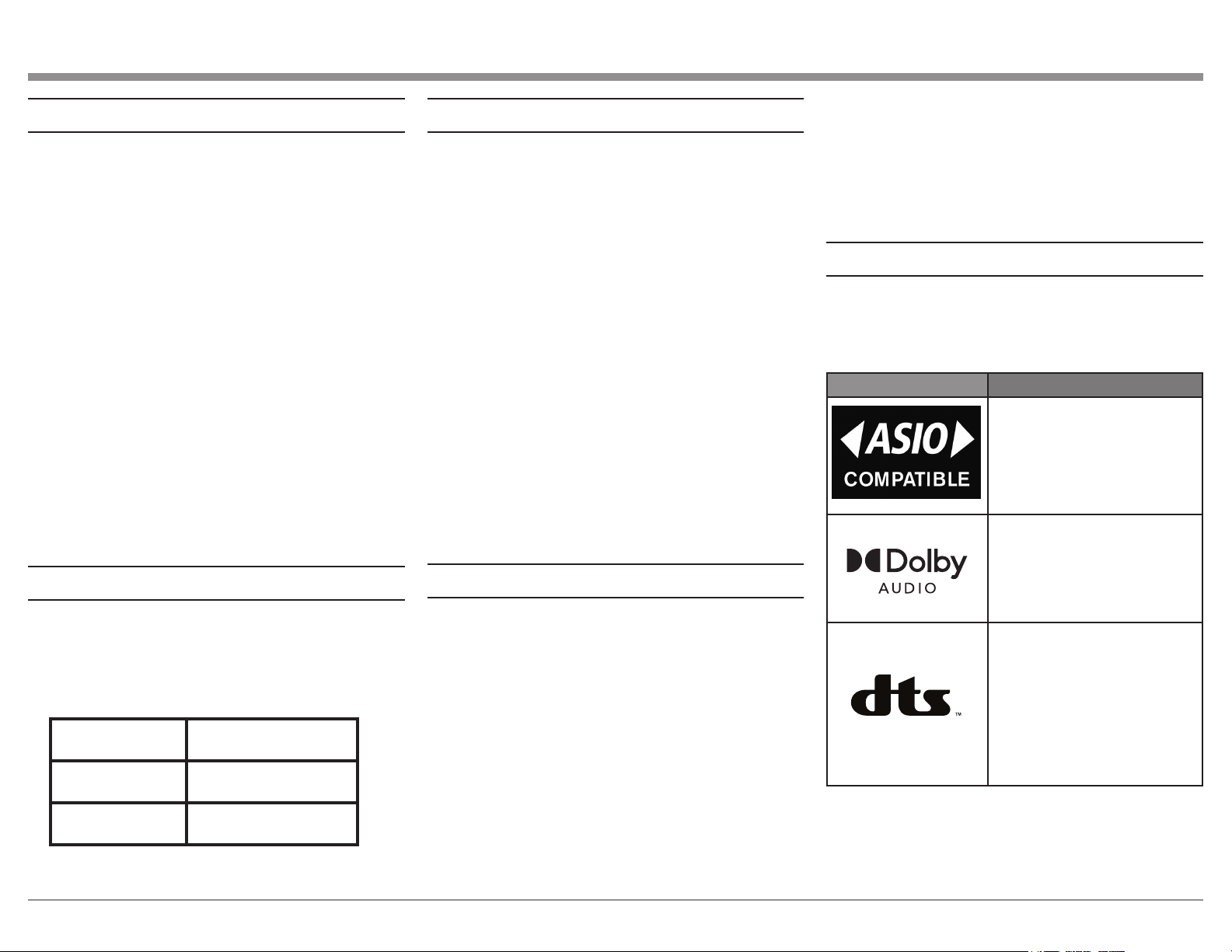
Trademark and License Information
The McIntosh MCD12000 incorporates copyright
technology that is protected by U.S. patents and other
intellectual property rights. The MCD12000 uses the
following Technologies:
Trademark License Information
ASIO is a trademark and
software of Steinberg Media
Technologies GmbH
Manufactured under license
from Dolby Laboratories.
Dolby, Dolby Audio, and the
double-D symbol are trade-
marks of Dolby Laboratories.
For DTS patents, see http://
patents.dts.com. Manufactured
under license from DTS, Inc.
DTS, the Symbol, DTS and
the Symbol together, and
Digital Surround are registered
trademarks and/or trademarks
of DTS, Inc. in the United
States and/or other countries.
DTS, Inc. All Rights Reserved.
• Advanced Transport with precision-Diecast
Aluminum Drawer
• R-Core Power Transformer and Multi-
Regulators Power Supply
• CD/DVD playability up to 24Bit/192kHz,
DSD128
4
Where to Put It
The MCD12000 can be placed upright on a table or
shelf, standing on its four feet. It also can be custom
installed in a piece of furniture or cabinet.
Always provide adequate ventilation for your
MCD12000. Cool operation ensures the longest
possible operating life for any electronic instrument.
Do not install the MCD12000 directly above a heat
generating component such as a high-powered
amplifier. If all the components are installed in a
single cabinet, a quiet running ventilation fan can be
a definite asset in maintaining all the system compo-
nents at the coolest possible operating temperature.
A custom cabinet installation should provide the
following minimum spacing dimensions for cool
operation:
• 6 inches (15.3cm) above the top
• 5/8 inches (1.6cm) below the bottom
• 2 inches (5.1cm) on each side of the MCD12000
so that airow is not obstructed
• 18 inches (45.7cm) depth behind the front panel
• 2 inches (5.1cm) in front for handle clearance
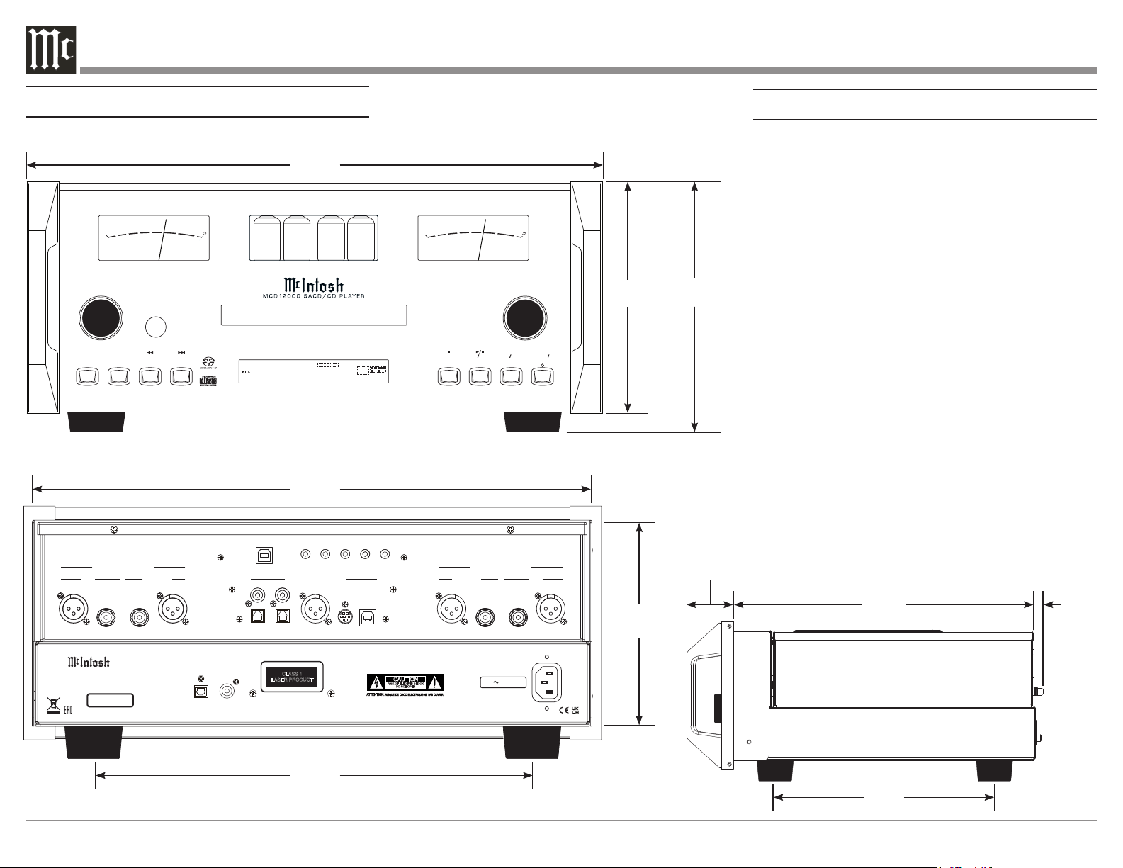
Dimensions
STAND BY ON
OPE N CLOS E
STOP
PLAY PAUS E
BAC K
DIS C LAYER NEX T
DIS PLAY/ TIM E
PUS H-M ENU
LIGHTS INPUT
SUPER
AUDIO CD
1
TRAC K
T PROG RA ND TOTAL SING REM
0 1 0 m 2 0 s
L.PCM
WMA MP3
L LFE
SL SR
C R
-60
-50
-40
-30
-20
-1 0
0
+3
O U T P U T L E V E L
-60
-50
-40
-30
-20
-1 0
0
+3
O U T P U T L E V E L
/
120V 50 60Hz 50W
COAXIAL
OPTICAL
DIGITAL
AUDIO OUTPUTS
SERIAL
NUMBER
HANDCRAFTED IN USA WITH US AND IMPORTED PARTS
McINTOSH LABORATORY, INC.,
BINGHAMTON, NY
SACD/CD PLAYER
MCD12000
CLASS 1
LASER PRODUCT
Product complies with CRF Title 21, Ch. 1,
Subchapter ‘J’, Sections 1010.2, 1010.3, 1040.10
and 1040.11, in effect at date of manufacture.
CAUTION
RISK OF ELECTRIC SHOCK
DO NOT OPEN
UNBALANCEDBALANCED UNBALANCED BALANCED
RIGHT AUDIO OUTPUTS
BALANCED UNBALANCED BALANCEDUNBALANCED
LEFT AUDIO OUTPUTS
SERVICE
DATA IN OUT IN
POWER
CONTROL
DIGITAL AUDIO INPUTS
MCT
AES/EBU
IR INRS232
TUBE SOLID STATE TUBESOLID STATE
COAX 1
OPTICAL 1
COAX 2
OPTICAL 2
USB
17-1/2"
44.5cm
Front View
7-5/64"
18cm
7-5/8"
19.4cm
16-5/8"
42.2cm
Rear View
6-3/16"
15.7cm
13-1/4"
33.7cm
10-9/16"
26.8cm
14-7/16"
36.7cm
1-1/2"
3.8cm
Side View
7/16"
1.1cm
5
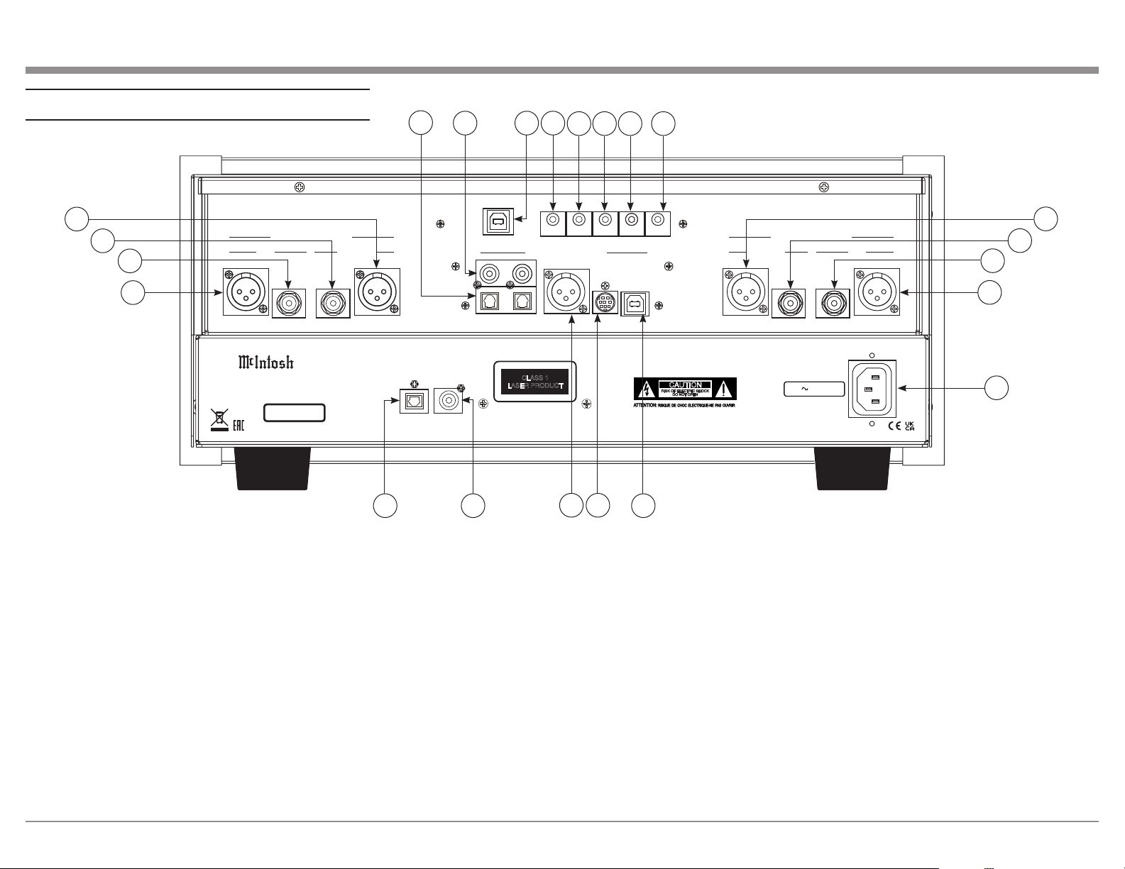
Navigating the Rear Panel
/
120V 50 60Hz 50W
COAXIAL
OPTICAL
DIGITAL
AUDIO OUTPUTS
SERIAL
NUMBER
HANDCRAFTED IN USA WITH US AND IMPORTED PARTS
McINTOSH LABORATORY, INC.,
BINGHAMTON, NY
SACD/CD PLAYER
MCD12000
CLASS 1
LASER PRODUCT
Product complies with CRF Title 21, Ch. 1,
Subchapter ‘J’, Sections 1010.2, 1010.3, 1040.10
and 1040.11, in effect at date of manufacture.
CAUTION
RISK OF ELECTRIC SHOCK
DO NOT OPEN
UNBALANCEDBALANCED UNBALANCED
BALANCED
RIGHT AUDIO OUTPUTS
BALANCED
UNBALANCED BALANCEDUNBALANCED
LEFT AUDIO OUTPUTS
SERVICE
DATA IN OUT IN
POWER
CONTROL
DIGITAL AUDIO INPUTS
MCT
AES/EBU
IR INRS232
TUBE SOLID STATE
TUBESOLID STATE
COAX 1
OPTICAL 1
COAX 2
OPTICAL 2
USB
1
2
3
4
4
3
2
1
5
6 7 8
9
10 11 12
13 14
18
1. Balanced Outputs (Solid State): These ports
produce Solid State signals using XLR connector
cables.
2. Unbalanced Outputs (Solid State): These ports
produce Solid State signals using RCA connector
cables.
3. Unbalanced Outputs (Tube): These ports produce
Tube signals using RCA connector cables.
4. Balanced Outputs (Tube): These ports produce
Tube signals using XLR connector cables.
5. Optical Inputs: These ports accept optical connec-
tions for digital signals.
6. Coax Inputs: Connect coaxial cables for digital
signals into these ports.
15 16
17
7. Service Port: This USB Type-B port will be used
for service purposes only.
8. RS232 Port: Using a 3.5mm-to-DB9 cable, you can
connect the device to a computer or another controller
device through here.
9. IR In Port: Connect an external IR sensor here
with a 3.5mm connector.
10. Data In: Using a 3.5mm data cable, this port
receives control data from a McInotsh Integrated
Amplifier or Preamplifier.
11. Power Control Out: Sends an On/Off signal to a
connected McIntosh component via a 3.5mm cable.
12. Power Control In: Receives an On/Off signal
from a connected McIntosh component via a 3.5mm
cable.
13. Optical Output: Connect an optical cable to
transmit a digital signal from this port via the DISC
input.
14. Coax Output: Connect a coaxial cable to transmit
a digital signal from this port via the DISC input.
15. AES/EBU: This port accepts a balanced digital
signal.
16. MCT Input: Used to transfer signals from
McIntosh products with an MCT connector.
17. USB Audio Input: A USB Type-B connector will
go here to receive a digital signal from a computer.
18. Main Power: Connect to a power outlet using
the included power cable to supply power to the
MCD12000.
6
WLAN ANT 1
WLAN ANT 2
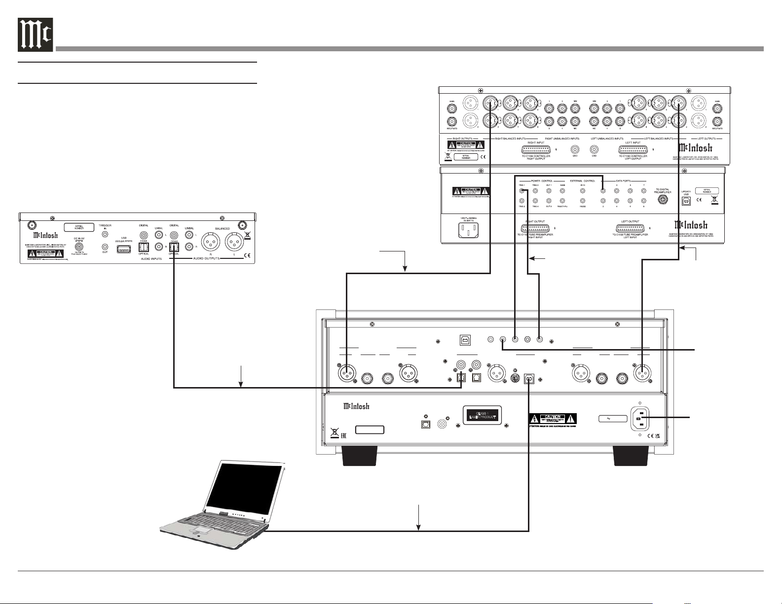
Connection Diagram
Here are some common connections for the
MCD12000:
/
120V 50 60Hz 50W
COAXIAL
OPTICAL
DIGITAL
AUDIO OUTPUTS
SERIAL
NUMBER
HANDCRAFTED IN USA WITH US AND IMPORTED PARTS
McINTOSH LABORATORY, INC.,
BINGHAMTON, NY
SACD/CD PLAYER
MCD12000
CLASS 1
LASER PRODUCT
Product complies with CRF Title 21, Ch. 1,
Subchapter ‘J’, Sections 1010.2, 1010.3, 1040.10
and 1040.11, in effect at date of manufacture.
CAUTION
RISK OF ELECTRIC SHOCK
DO NOT OPEN
UNBALANCEDBALANCED UNBALANCED
BALANCED
RIGHT AUDIO OUTPUTS
BALANCED
UNBALANCED BALANCEDUNBALANCED
LEFT AUDIO OUTPUTS
SERVICE
DATA IN OUT IN
POWER
CONTROL
DIGITAL AUDIO INPUTS
MCT
AES/EBU
IR INRS232
TUBE SOLID STATE
TUBESOLID STATE
COAX 1
OPTICAL 1
COAX 2
OPTICAL 2
USB
IR Sensor
Connect to
AC Power
Outlet
USB Cable to Computer
Digital signals can be sent to
Optical or COAX Inputs
Output can be sent via
Balanced or Unbalanced
cables (Right Balanced Tube)
Output can be sent via
Balanced or Unbalanced
cables (Right Balanced
Tube)
Connect a
Power Control
(Trigger) cable from
Preamp to Power
Control IN
7
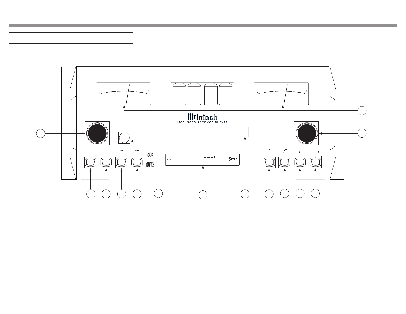
Navigating the Front Panel
STANDBY ON
OPEN CLOSE
STOP
PLAY PAUSE
BACK
DISC LAYER NEXT
DISPLAY/TIME
PUSH-MENU
LIGHTS INPUT
SUPER
AUDIO CD
1
TRA CK
T PRO G RAN D
TOTAL SI NG REM
0 1 0 m 2 0 s
L.PCM
WMA MP3
L LFE
SL SR
C R
-60
-50
-40
-30
-20
-1 0
0
+3
O U T P U T L E V E L
-60
-50
-40
-30
-20
-1 0
0
+3
O U T P U T L E V E L
1
2 3 4 5
6
7
8 9
10
11 12
13
1. Lights/Push-Menu Knob: This knob controls the
Meter and Tube lights (On/Off). It also allows you
to enter the Setup Menu by pushing it. Rotating the
knob while in the Seteup Menu allows you to navigate
through the menu options.
2. Display/Time Button: Cycles between showing on
the display the Total Remaining Time, Single Track
Remaining Time, or Track Time.
3. Disc Layer Button: Toggles between CD, STEREO
(SACD), and MULTI (SACD) playback.
4. Back Button: Play previous track.
5. Next Button: Play next track.
14
6. Infrared Sensor: This is how the MCD12000
receives commands from your Remote Control.
7. Vacuum Fluorescent Display (VFD): Displays
Menu and playback information.
8. Disc Tray: Where you insert your CDs.
9. Stop Button: Cancels media playback and resets
progress through it.
10. Play/Pause Button: Halts playback of active
media and will resume from where it left off if you
press the button again.
11. Open/Close Button: Opens and closes the Disc
Tray.
12. Standby/On Button: Turns MCD12000 On/Off.
When the MCD12000 unit is in Standby (turned Off),
the LED above the button will be green if Auto-Off is
enabled, or red if Auto-Off is disabled (see Page 10).
13. Input Knob: Rotate this to select different Input
sources for playback.
14. Output Level Meters: Indicates the signal level
being delivered from the Outputs.
8
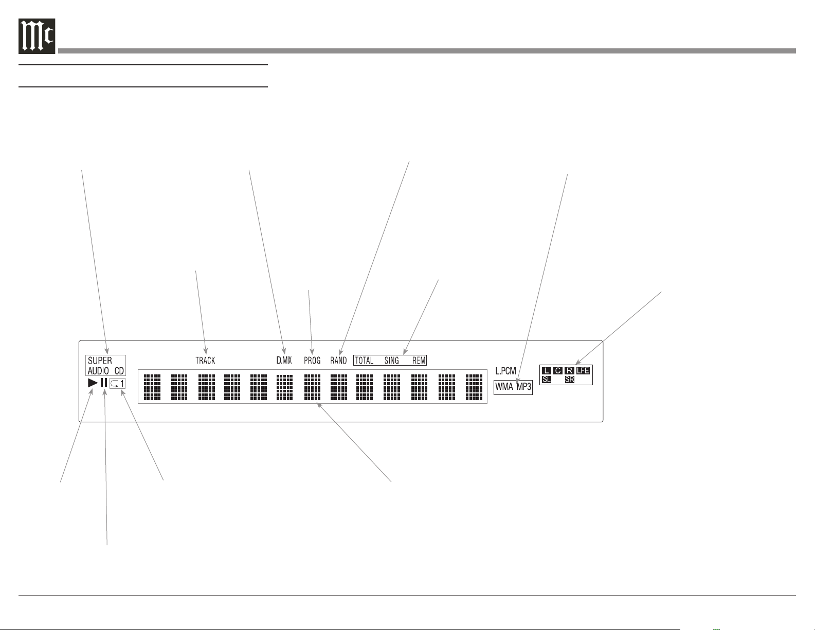
Navigating the Display
Indicates the type
of disc loaded,
CD or SACD
Indicates when
in the Pause
Mode
Indicates when
the Play Mode
is active
Indicates the
PROGramming
or Program
Play Mode is
active
Indicates the number of tracks on the Disc, Programmed
Tracks, the current Track Time, Remaining Track Time,
Total Disc Playing Time, Text and various other Informa-
tion
Indicates the RANDom
Play Mode is active
Indicates when the tracks on the
disc are MP3 or WMA encoded.
L.PCM indictes WAV encoded
Indicates the Repeat
Mode selected; Repeat
All (Tracks) or Repeat
1 (Track)
Indicates when the
TRACK Number is
being displayed
Indicates the total disc
remaining playback time or
the current track remaining
playback time
Indicates the sound channels on a CD or SACD
Disc. Left and Right Channels for a CD or
SACD Disc;
Left, Center, Right, LFE (subwoofer), Surround
Left and Surround Right on a Multichannel
SACD Disc.
Indicates the MultiChannnel
Layer of the SACD Disc is
active.
9
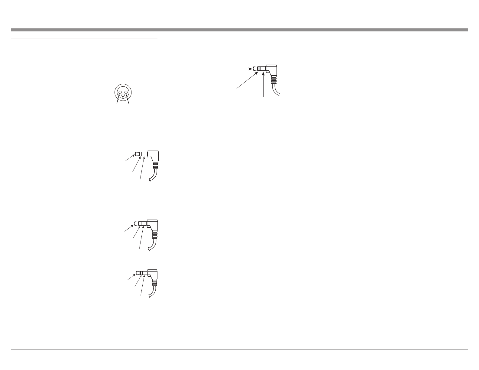
RS232 Port Connector
The RS232 Port uses a 3.5mm stereo mini phone plug
to connect to external third-party controllers.
Connector and Cable Information
XLR Connectors
Below is the Pin configuration for the XLR Balanced
Outputs and Digital (AES/EBU) Input Connectors on
the MCD12000. Refer to the diagram for connection:
PIN 1: Shield/Ground
PIN 2: + Output/+ Signal
PIN 3: - Output/- Signal
Power Control Trigger Connectors
The Power Control Trigger Output Jack sends while
the Power Control Trigger Input Jack
receives Power On/Off Signals (+12
volt/0 volt) when connected to other
McIntosh Components. An addi-
tional connection is for controlling
the level of the Output Meters on
McIntosh Power Amplifiers, as well
as the built-in Output Level Meters.
A 3.5mm stereo mini phone plug is used for this con-
nection.
Data Port Connectors
The Data In Port receives Remote
Control Signals from a Source Com-
ponent. A 3.5mm stereo mini phone
plug is used for connection.
IR IN Port Connectors
The IR IN Port also uses a 3.5mm
stereo mini phone plug and allows the
connection of other brand IR Receiv-
ers to the MCD12000.
PIN 1
PIN 2
PIN 3
Power
Control
Meter
Illumination
Control
Ground
Main, Trig 1&2
and Pass-Thru
Data
Signal
N/C
Data
Ground
IR Data
Control
Ground
N/C
USB Audio
The USB AUDIO input of the MCD12000 provides
the capability to receive music/sound in a digital
format from a connected computer.
Software Requirements
Apple
®
Macintosh
®
computers require OS-10.6.8 or
later. Apple computers require no additional driver
install to communicate with the MCD12000.
For Windows-based computers (PC), Windows 7 (SP1)
or later is required. The correct McIntosh USB Audio
driver must be installed for the PC to communicate
with the MCD12000.
To install the McIntosh USB Driver for Windows-
based computers:
Download the latest driver from the McIntosh
website: https://www.mcintoshlabs.com/products/
cd-players/MCD12000
The driver can be found in the Downloads section of
the webpage under Software Updates.
• Unzip the McIntosh_UsbAudio le
• Run the File
• Choose “Yes” to allow changes to your
computer
• Follow software prompts selecting “Next” or
“Install” as needed
• Click “Finish” when drvier is installed
Next, connect the Computer to the MCD12000 using a
USB 2.0 Cable Type A to Type B.
Windows should detect the new device (if you
installed the driver software as directed above) and
install the driver as indicated by a message in the
lower part of your monitor.
You can use the Windows Control Panel to select the
new audio device which will appear as “McIntosh
HD-HS 2 [ASIO] USB Audio”. You may also select
this driver in many third-party applications such as
JRiver Media Center.
The MCD12000’s display will show the sampling rate
or bit rate for the USB input.
USB Service Port
The USB SERVICE PORT on the rear of the
MCD12000 is for McIntosh service use only. Use the
USB AUDIO port for audio input.
MCT
The Digital MCT Input directly decodes SACD/CD
signals from an external Transport component.
The MCT Input uses a McIntosh designed custom
cable, part number 171923. This cable is only supplied
with McIntosh MCT Transport products.
Optical
The two Optical Inputs allow digital sources to be
connected to the MCD12000 using TOSLINK cables
also known as “optical audio cables.”
Coax
The two Digital Coax (Coaxial) Inputs allow digital
sources to be connected to the MCD12000 using
Digital Audio RCA Coaxial Cables.
Tip: MCD12000 TXD Out
Data Being Transmitted from MCD12000
Ring: MCD12000 RXD In
Data Being Received by MCD12000
Ground
10
Powering on the MCD12000
To power on the MCD12000, press Standby/On
Button. To power the MCD12000 off, do this again.
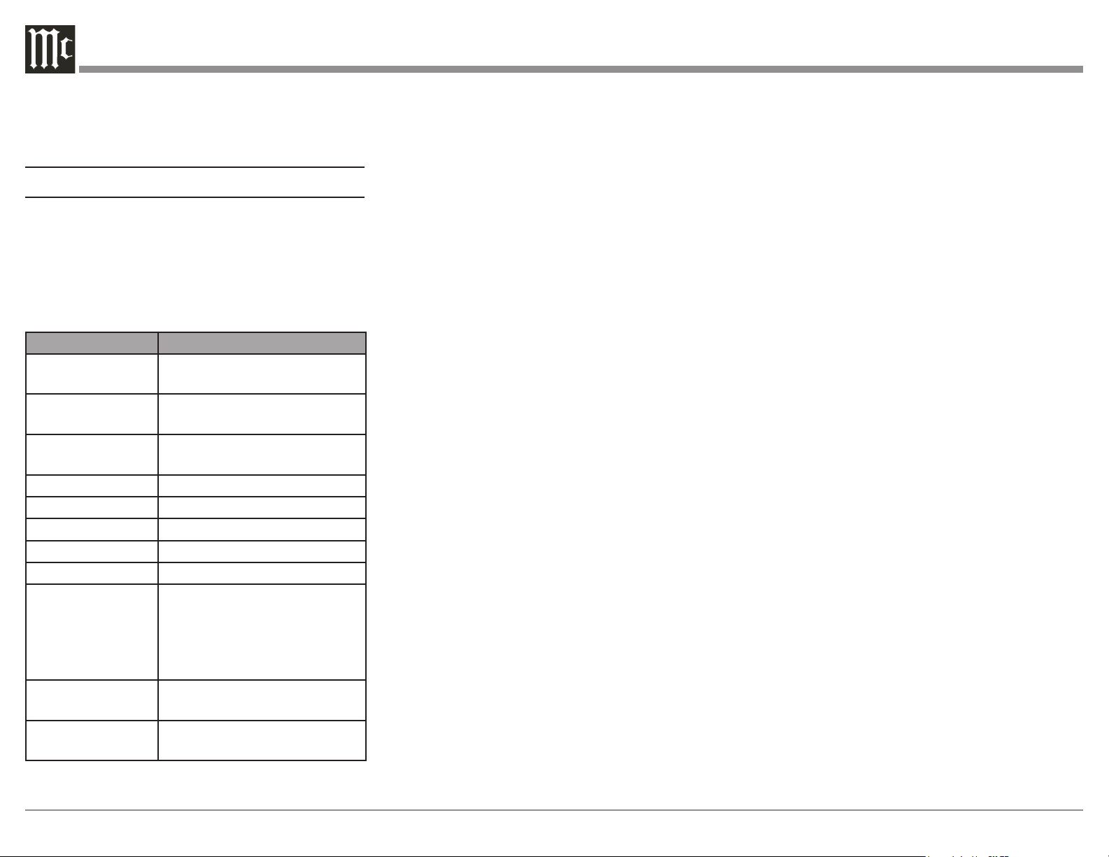
Using the Setup Menu
To enter the Setup Menu, push and release the Left
Knob. Turning the Left Knob will scroll through the
available options.
The following is a table listing the Setup Menu's
dierent Settings options and their available con-
gurations:
Setting Options
MCD12000 Displays current firmware ver-
sion
S/N AJDxxxx Displays the serial number of
the MCD12000
DI FW Vx.x Displays the current firmware
for the digital interface module
Auto-Off ON (default) / OFF
IR Code Norm (default) / Alt
Front IR ON (default) / OFF
Power IR ON (default) / OFF
IR Input ON (default) / OFF
Inputs (HOLD)
Hold Left Knob to
enter submenu
Submenu Choices: COAX 1,
COAX 2, OPT 1, OPT 2, USB,
MCT, AES/EBU
Options for each: ON (default)
/ OFF
BAUD 115200 (default), 9600, 19200,
38400, 57600
Factory Reset Press and hold Left Knob to
perform Factory Reset
Firmware Version
Firmware is internal software that controls the
MCD12000’s functionality.
The version of the main firmware of the MCD12000
can be viewed by entering the Setup Menu. Enter
this by pressing and releasing the Left Knob. The
first setting is called MCD12000. The number to the
right is the version number. For example, if the VFD
displays “MCD12000 V1.01”, then the main firmware
is version 1.01.
There is also firmware for controlling the digital audio
hardware. To see the Digital Input (DI) firmware
version, enter the Setup Menu. Rotate the Left Knob
until you see “DI FW”. The number following the V to
the right is the Digital Input firmware version.
Firmware upgrades when available can be installed by
qualified technicians.
Serial Number
The MCD12000’s unique serial number can be viewed
by entering the Setup Menu and rotating the Left
Knob until you see “S/N:”. The number (and letters)
to the Right are the unit’s serial number. This number
can also be found on the rear of the unit.
Auto-Off
Auto-Off can be toggled On (default) or Off. Enter the
Setup Menu. Select On or Off by rotating the Right
Knob.
When enabled, the Auto-Off feature powers off the
MCD12000 when no audio input or user interaction
has been detected for approximately 30 minutes.
When the MCD12000 unit is in Standby (turned Off),
the LED above the button will be green if Auto-Off is
enabled, or red if Auto-Off is disabled.
If the Power Control In port on the MCD12000 is
connected to a source component, the Auto-Off
feature will be disabled automatically.
IR Code
The IR Code setting allows you to select an alternative
set of remote control codes to use for the remote
control of the MCD12000. The default is to use the
Normal control codes which will be perfectly fine for
the vast majority of situations. If you have another unit
being controlled with the same control codes, conflicts
can arise. If this is the case, change IR Code setting
to “Alt”. The remote control for the MCD12000 must
also be set to use the alternate codes.
To set the MCD12000’s remote control to use alternate
(Alt) codes, press and hold the SELECT button and
press the “2” button. Hold until the two LEDs to the
right of the SHIFT button flash twice.
To set the MCD12000’s remote control to use normal
codes, press and hold the SELECT button and press
the “1” button. Hold until the two LEDs to the right of
the SHIFT button flash twice.
Front IR
Front Panel Sensor, which receives the signals from
the Remote Control, can be switched off to prevent
interference when an external IR Sensor is connected.
To de-activate the Front IR, enter the Setup Menu.
Select On or Off by rotating the Right Knob.
Power IR and IR Input
The MCD12000 can be controlled by another
McIntosh unit’s remote control using the DATA IN
PORT. This is convenient for using commands on the
other remote such as PLAY or NEXT, but it is possible
that you may not want Power commands or Input
commands sent by the connected unit to control the
MCD12000.
If you wish to disable Power Commands coming from
the DATA PORT or from a connected external IR
sensor connected the IR IN, enter the Setup Menu.
Select On or Off by rotating the Right Knob.
Note: When AC Power is initially applied to the
MCD12000, the unit will momentarily switch On
and then go into the Standby Mode.

11
Input Setup
You have the ability to control which inputs appear on
the display when you rotate the Input (Right) Knob.
If you wish to remove an unused input or restore a
previously removed input:
• Push and release the Left Knob to enter Setup
• Rotate the Left Knob until the VFD displays
“Inputs (Hold)”
• Press and Hold the Left Knob for two seconds.
“CD PLAYER” will appear in the VFD
• Rotate the Left Knob to select the input you
wish to display or hide
• Rotate the Right Knob to select On or O
• Press and release the Left Knob twice to exit the
Setup Menu
Baud Rate Setup
The MCD12000 can be controlled remotely via the
RS232 Jack. The settings for serial communications
are:
• 8 bit, No parity and 1 stop bit
The speed can be adjusted from the Setup Menu.
To adjust the BAUD rate, enter the Setup Menu.
Rotate the Left Knob until you reach “BAUD: …”
Rotate the Right Knob to select from the following
options:
• 9600, 19200, 38400, 57600, and 115200
(default).
Factory Reset
Use the FACTORY RESET option if you wish to
return all settings to factory defaults. All previous
setup changes will be lost.
To Factory reset the MCD12000, enter the Setup
Menu. Rotate the Left Knob until “FACTORY
RESET” appears on the display. Hold the Left Knob
down until “In Progress” appears on the screen. When
the Factory reset is complete, the MCD12000 will
power off.
Playing/Navigating a Disc
• Rotate the Right Knob (INPUT) until CD
PLAYER appears on the Display
• Press and release the OPEN/CLOSE button to
open the tray
• Place the disc, label side up, on the tray
• Press and release the OPEN/CLOSE button to
close the tray
• “Reading” will appear on the Display followed
by Disc information
• You may press the BACK and NEXT buttons to
pick a particular track
• Press and release the PLAY/PAUSE button to
Play; press again to Pause
Additional commands are available on the Remote
Control. See “Navigating the Remote Control” on
Page 14.
The Program Playback feature allows the playback of
selected tracks in a chosen order. To use this feature,
Press the SHIFT button on the Remote Control and
then press the RANDOM button twice. Use the
numeric buttons to enter the desired tracks. Press the
PLAY button to begin playing the programmed tracks.
Navigating CD-ROMs
The Remote Control buttons 2, 4, 6 and 8 can be used
for navigating up, down, left, right through tracks/
folders on a CD-ROM. The 5 button can be used
to Enter the folder or Play the track shown on the
Display. For navigating data discs, please see Page 12.
12
Using Remote for MP3/WAV, Data Play-
back
Load a DATA (CD or DVD) or MP3/WAV Disc
into the MCD12000. The MCD12000 has different
Operational Playback Modes when a Disc contains
DATA music files. The Operational Mode Selection
includes the “All Mode” and the “Folder Mode”, which
are indicated by the Front Panel Display.
To check the current Operation Mode, press the
MODE button on the Remote Control once. To change
the current Operation Mode, press the MODE button
twice, followed by pressing the PLAY button to
activate the selected Operation Mode.
When conventional CD or SACD DISCs are played,
all the sound tracks are sequentially numbered and
are played back in that numeric order. This standard
playback mode is referred to as the “All Mode” of
operation.
CD Data, DVD Data, and MP3/WAV Discs are
usually created on a computer, which can create
multiple folders that are in a sequential order. Each
folder can contain multiple sound tracks that are in a
sequential order. This playback mode is referred to as
the “Folder Mode” of operation. Refer to “Front Panel
Display” for an example of the Front Panel Indications
of the Folder Mode content.
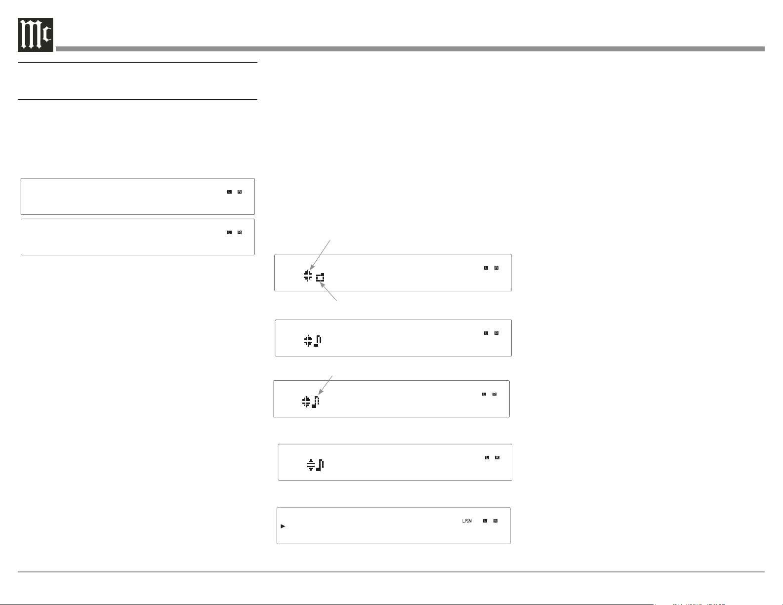
All Mode
Folder Mode
Front Panel Display
When playing a Data CD Disc or Data DVD Disc, the
MCD12000 Front Panel Information Display will also
indicate the following:
• Folder or Sub-Folder Name - Music One
• Artist Name - Freddie King
• Album Name - Getting Ready
• Track Name - 09 Tore Down
• Audio Format Type and Sampling Frequency - WAV
44.1kHz
Getting Ready-
Freddie King -
Music One
09-Tore Down.
WAV 44.1kHz
Folder Symbol
Upper and Lower Symbol
Music Symbol
After the Folder Mode has been selected, the Front
Panel Information Display will indicate the Folders,
Sub Folders, and Tracks. It also indicates the Album
Name, the Artist Name, the Track Name, and the
Track Time, along with the Audio Format Type
and Sampling Frequency. Due to the operational
differences of various computers and the MCD12000,
sequel listing of the Folders, Sub Folders and Tracks
will usually be different. If the All Mode on the
MCD12000 was selected, the sequential listing will
also be different.
Display Brightness
There are three available Settings for the Front Panel
Display. The choices include brightness settings of
high (default setting), medium or low. To change the
brightness setting perform the following steps:
1. Select CD Player/ DISC Input
2. Press the SHIFT Push-button.
3. Momentarily press the 2 (DIM) button to change
the current brightness setting. Repeat this until the
desired brightness setting is selected.

13
Starting Playback
1. Use the INPUT Control or INPUT button on the
Remote Control to select DISC/CD Player.
2. Using the Remote Control, press the Number 5
button to start playback.
3. If the desired track for playback is located in a
different folder, press the Number 4 button first. Then,
use the Number 2 (select the Upper ▲ Data Folder)
or Number 8 (select the Lower ▼ Data Folder) button
to select the desired folder. Select the desired Track
using the Number 2 or Number 8 button. Once the
Desired Track Name is indicated on the Front Panel
Information Display, press the Number 5 button to
start playback of the track.
Note: Once the desired folder has been selected,
the Remote Control NEXT button can be
used to select the desired track. Then, the
Remote Control PLAY Pushbutton when
pushed will start playback of the track.
4. While the track just selected is playing back, the
Front Panel Display may also indicate the Track
Name, followed by the Artist Name and/or the Album
Name by pressing the MENU/TEXT button several
times.
5. Press the DISPLAY/TIME button (once or twice) to
indicate on the Front Panel Display the Audio Format
Type and Sampling Frequency of the track that is
playing back.
Selection of a Different Sub Folder
1. Press the Number 4 button. The Front Panel Display
will indicate the name of the current folder.
2. Press the Number 2 button to select an Upper▲
Data Folder or press the Number 8 button to select a
Lower▼ Data Folder. Once the desired folder has been
selected, push the Number 6 button once to identify
the first track in the folder. Press the Number 6 button
to start playing the first track from the selected folder,
or press the Number 6 button a second time to start
playing the second track.
3. Press the MENU/TEXT button to display the Artist
Name, followed by the Album Name, and then the
Track Name and Number.
4. Press the DISPLAY/TIME button to display the
track number display time. Press the DISPLAY/
TIME Push-button a second time to display the Audio
Format Type and the Sampling Frequency.
Resetting the Microprocessor
In the unlikely event the MCD12000 stops function-
ing properly and the Factory Reset procedure (see
“FACTORY RESET” on Page 11) does not solve the
issue, you can try the following procedure to reset the
secondary (transport) microprocessor:
• Power o the MCD12000
• Remove the AC power cord from the rear of the
MCD12000
• Wait a few seconds for the standby LED to turn
o
• Push and Hold the NEXT button in while
pressing and holding the STOP button
• Plug the AC power cord into the rear of the
MCD12000
• When “INITIALIZED” appears on the Display,
release the NEXT button and STOP button
The MCD12000 should be reset in a few more
seconds.
14
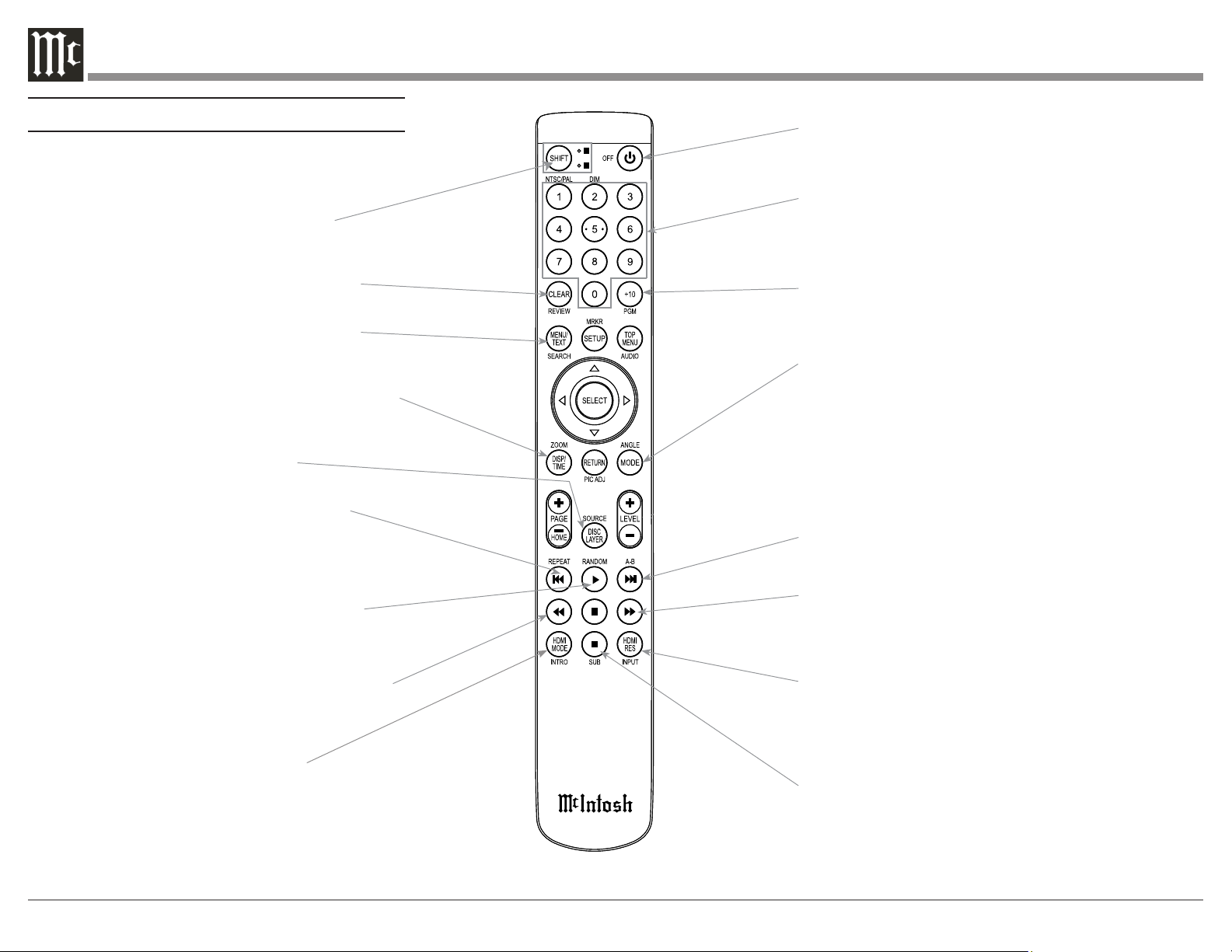
Note: The Remote Control Push-buttons not identified are for use with other McIntosh Products
Momentarily press to Power ON or OFF
Use to select disc tracks or
any numbered operation
Use to direct access tracks 10 and above
Selects the All MODE or the Folder MODE for
navigating and selection of music on a CD-R or
DVD ±R and Flash Drive
LEVEL Control adjusts the volume level for the
Rear Panel Variable Audio Output Connectors and
the Front Panel Headphone Jack
Press to play the next Selection
Press to FAST-FORWARD thru the current selection
Select Disc, USB Mode or Coax/Optical Digital Inputs
Press to STOP disc playback
SHIFT push-button with LED Indicators
used to select a push-button function
with white or gold color nomenclature
Use to CLEAR the last programmed track
Access the TEXT Display Mode when playing a
SACD Disc containing the information
Use to select various disc information, including
TIME, on the Front Panel DISPlay. It is also used
to cancel the text display mode on a SACD Disc
Use to select the SACD or CD Tracks
from a hybrid disc for playback
Press to play the Previous Selection.
Also used to select one of various REPEAT
modes
Press once to PLAY, a second time to PAUSE
and a third time to RESUME playback. Also
used to activate RANDOM playback of the
tracks on a SACD or CD disc
Press to FAST-REVERSE thru the current
selection
Navigating the Remote Control
Press to toggle
Meter or Tube Lights ON or OFF

15
Changing Remote Control Batteries
Someday, the two AAA battery in the Remote Control
will need to be replaced. To replace the two AAA
batteries:
• Locate the battery door. Looking at the back of
the remote, the battery door is in the lower part
• Slide battery door towards the bottom of the
Remote Control. The battery door will slide
open 1/4 inch (0.63cm)
• Lift the door up to reveal the batteries
• Remove the old batteries
• Insert two new AAA batteries noting the polarity
which is printed on the bottom of the battery
compartment. The spring will connect with the
negative (-) part of the battery
• Place the door over the batteries leaving a
1/4 inch gap
• Slide the door up towards the top of the remote
to secure
Note: If at any time the Player seems unresponsive to
the desired Remote Control Command, it may be
necessary to select the color of the push-button
nomenclature for the desired command. This
is accomplished by first pressing the SHIFT
Push-button to select gold, as indicated by the
LED, and then within 3 seconds pressing (or in
the case of some functions repeatedly pressing)
the desired command push-button.
16

17
18
Audio Specications
Disc Formats
CD, SACD, CD-R, CD-RW, and DVD (DATA)
Fixed Output level
2.0Vrms Unbalanced
4.0Vrms Balanced
Output Impedance
600 ohms Unbalanced and Balanced
Frequency Response
4Hz to 20,000Hz, ±0.5dB (CD)
4Hz to 40,000Hz, +0.5, -2dB (SACD)
Signal to Noise Ratio
110d B (A-weighted)
Dynamic Range
Better than 100dB
Harmonic Distortion
0.003% @ 1,000Hz
Channel Separation
Better than 98dB (1,000Hz)
Playable Disc Media Files
Format Up To Frequency/
Bit
Bit Rate
MP3 (.mp3) 48kHz up to 320kbps
WMA (.wma) 48kHz up to 320kbps
AAC (.aac/
mp4)
48kHz up to 320kbps
WAV (.w a v) 192kHz/24 Bit* uncompressed
FLAC (.f lac) 192kHz/24 Bit* uncompressed
ALAC (.m4a) 96kHz/24 Bit* uncompressed
AIFF (.aif/aiff) 192kHz/24 Bit* uncompressed
DSD (.dff/dsf) DSD128 (5.6MHz) uncompressed
*up to 48kHz with CD-R/+RW
Digital Audio Specications
Digital Input Format
SPDIF (PCM
1
)
Digital Inputs
Coaxial: 0.5V p-p/75 ohms
Optical: - 15dbm to -21dbm (TOS Link)
MCT: 0.5V p-p/75 ohms
USB: USB 2.0 Type B Connector
Digital Input Sample Rate
Coaxial: 16, 24-Bit/192kHz, Dolby Digital, DTS
Optical: 16, 24-Bit/192kHz, Dolby Digital, DTS
MCT: SACD, PCM: 16, 24-Bit/44.1kHz to 192kHz
USB: PCM: 16, 24, 32-Bit/44.1kHz to 384kHz
DXD: DXD352.8kHz, DXD384kHz
DSD: DSD64, DSD128, DSD256, DSD512
Digital Audio Output Format
Coaxial and Optical: SPDIF (PCM
1
), IEC958
44.1kHz to 192kHz/24Bit
Digital Outputs
Coaxial: 0.5V p-p/75 ohms
Optical: - 15dbm to -21dbm (TOS Link)
Digital Output Sample Rate
Up to 24-Bit/192kHz for DISC Input only
1
PCM (Pulse Code Modulation) Digital Signal type used for
CD Discs
General Specications
Transport
Laser Type: Twin Beam
Laser Beam Wavelength: 650nm (SACD)/790nm (CD)
Laser Power: CLASS IIa/CLASS I
Power Requirements
100 Volts, 50/60Hz at 50 watts
110 Volts, 50/60Hz at 50 watts
120 Volts, 50/60Hz at 50 watts
127 Volts, 50/60Hz at 50 watts
220 Volts, 50/60Hz at 50 watts
230 Volts, 50/60Hz at 50 watts
240 Volts, 50/60Hz at 50 watts
Standby: Less than 0.5 watt
Note: Refer to the rear panel of the MCD12000 for the
correct voltage.
Overall Dimensions
Width is 17-1/2 inches (44.4cm)
Height is 7-5/8 inches (19.4cm)
Depth is 19 inches (48.3cm) including the Front Panel
Handles and Cables
Note: When the Disc Tray is opened, the panel clear-
ance required in front of mounting panel is 6-3/4
inches (17.2cm).
Weight
32.5 pounds (14.7Kg) net, 48 pounds (21.8Kg) in
shipping carton
Shipping Carton Dimensions
Width is 27 inches (68.6cm)
Depth is 25 inches (63.5cm)
Height is 14 inches (35.6cm)
Remote Control
McIntosh HR086
19
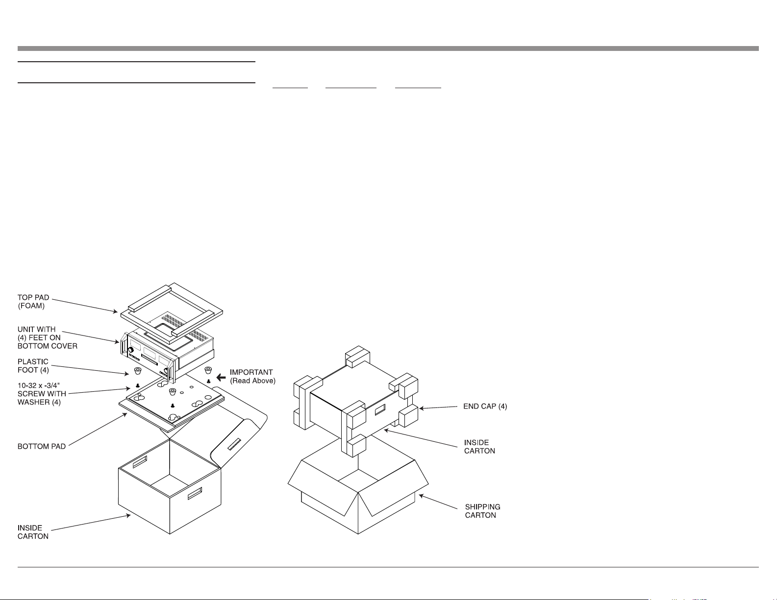
Packing the MCD12000
When shipping the MCD12000, it is highly recom-
mended that the unit be packed as it was originally
shipped to avoid damage. Failure to properly pack
the unit will likely result in damage. (The front panel
is made of glass!) If you need any of the packing
material, you can contact McIntosh Customer Service.
Use only packing material that is in good condition
and replace any material that has seen better days.
It is very important that the four plastic feet are
properly placed in the holes of the Foam Bottom Pad.
This will ensure the proper equipment location for
shipping. Failure to do this will result in shipping
damage.
Quantity Part Number Description
1 033888 Shipping Carton
1 034692 Pad Bottom
1 034691 Foam Top - Inner Carton
1 033697 Inner Box
1 033739 Poly Bag
20" W X 10" D X 36" L
4 034670 End Cap
4 017937 Plastic Foot
4 400159 10-32 X 3/4" Screw
4 404080 #10-7/16" Flat Washer

The continuous improvement of its products is the
policy of McIntosh Laboratory Incorporated who
reserve the right to improve design without notice.
Printed in the U.S.A.
McIntosh Laboratory, Inc.
2 Chambers Street
Binghamton, NY 13903
www.mcintoshlabs.com
McIntosh Part No. 24112701