
Owner's Manual
£RI:IFTXMRN°
19.5 HP
ELECTRIC START
42" MOWER
6 SPEED TRANSAXLE
LAWN TRACTOR
Model No,
917,270815
• Safety
• Assembly
• Operation
• Maintenance
• Repair Parts
CAUTION:
Read and follow all
Safety Rules and Instructions
before operating this equip-
ment.
For answers to your questions
about this product, Call:
1-800-659-5917
Sears Craftsman Help Line
5 am - 5 pro, Mort - Sat
Sears, Roebuck and Co., Hoffman Estates, IL 60179
Visitour Craftsman website: www.sears.com/craftsman
Warranty ............................................... 2
Safety Rules ......................................... 2
Product Specifications .......................... 5
Assembly .............................................. 7
Operation ............................................ 10
Maintenance Schedule ...................... 17
Maintenance ....................................... 17
Service and Adjustments .................... 21
Storage ............................................... 27
Troubleshooting .................................. 28
Repair Parts........................................ 32
Parts Ordering ..................... Back Cover
LIMITED TWO YEAR WARRANTY ON CRAFTSMAN RIDING EQUIPMENT
For two (2) years from the date of purchase, if this Craftsman Riding Equipment is
maintained, lubricated and tuned up according to the instructions in the owner's
manual, Sears will repair or replace, free of charge, any parts found to be defective in
material or workmanship.
This Warranty does not cover:
• Expendable items which become worn during normal use, such as blades, spark
plugs, air cleaners, belts, etc.
• Tire replacement or repair caused by punctures from outside objects, such as nails,
thorns, stumps, or glass.
• Repairs necessary because of operator abuse, negligence, improper storage or
accident or the failure to maintain the equipment according to the instructions
contained in the owner's manual.
• Riding equipment used for commercial or rental purposes.
LIMITED 90 DAY WARRANTYON BATTERY
For ninety (90) days from date of purchase, if any battery included with this riding
equipment proves defective in material or workmanship and our testing determines the
battery will not hold a charge, Sears will replace the battery at no charge. In-home
warranty service on your Craftsman riding equipment is available at no charge for 30
days from the date of purchase. Please contact your nearest service center. After 30
days from the date of purchase, warranty service is available by taking your Craftsman
riding equipment to your nearest Sears Service Center. (In-home warranty service will
still be available after 30 days from the date of purchase but a standard trip charge will
apply). This warranty applies only while this product is in the United States. This
Warranty gives you specific legal rights, and you may also have other rights which may
vary from state to state.
Sears, Roebuck and Co., D/817 WA, Hoffman Estates, IL 60179
IMPORTANT: This cutting machine is
capable of amputating hands and feet
and throwing objects, Failure to observe
the following safety instructions could
result in serious injury or death.
GENERAL OPERATION
• Read, understand, and follow all
instructions in the manual and on the
machine before starting.
• Only allow responsible adults, who are
familiar with the instructions, to operate
the machine.
• Clear the area of objects such as rocks,
toys, wire, etc., which could be picked
up and thrown by the blade.
• Be sure the area is clear of other
people before mowing, Stop machine if
anyone enters the area.
• Never carry passengers.
• Do not mow in reverse unless abso-
lutely necessary. Always look down
and behind before and while backing.
• Be aware of the mower discharge
direction and do not point it at anyone.
Do not operate the mower without
either the entire grass catcher or the
guard in place.
• Slow down before turning.
2
• Never leave a running machine
unattended. Always turn off blades, set
parking brake, stop engine, and remove
keys before dismounting,
•Tum off blades when not moWing.
• Stop engine b6fore removing grass
catcher or unclogging chute.
• Mow only in daylight or good artificial
light.
• DO not operate the machine while
under the influence of alcohol or drugs.
• Watch for traffic when operating near or
crossing roadways.
• Use extra care when loading or
unloading the machine into a trailer or
truck.
• Data indicates that operators, age 60
years and above, are involved in a
large percentage of riding mower-
related injuries. These operators should
evaluate their ability to operate the
riding mower safely enough to protect
themselves and others from serious
injury.
SLOPE OPERATION
Slopes are a major factor related to loss-
of-control and tipover accidents, which
can result in severe injury or death. All
slopes require extra caution. If you cannot
back up the slope or if you feel uneasy on
it, do not mow it.
DO:
• Mow up and down slopes, not across.
• Remove obstacles such as rocks, tree
limbs, etc.
• Watch for holes, ruts, or bumps. Uneven
terrain could overturn the machine. Tall
grass can hide obstacles.
• Use slow speed. Choose a low gear so
that you will not have to stop or shift
while on the slope.
• Follow the manufacturer's recommen-
dations for wheel weights or counter-
weights to improve stability.
• Use extra care with grass catchers or
other attachments. These can change
the stability of the machine.
• Keep all movement on the slopes slow
and gradual. Do not make sudden
changes in speed or direction.
• Avoid starting or stopping on a slope. If
tires lose traction, disengage the blades
and proceed slowly straight down the
slope.
DO NOT:
• Do not turn on slopes unless neces-
sary, and then, turn slowly and gradual-
ly downhill, if possible.
• Do not mow near drop-offs, ditches,or
embankments. The mower could
• suddenly turn over if a wheel is over the
edge of a cliff or ditch, or if an edge
caves in.
• Do not mow on wet grass. Reduced
traction could cause sliding.
• Do not try to stabilize the machine by
puffing your foot on the ground.
• Do not use grass catcher on steep
slopes.
CHILDREN
Tragic accidents can occur if the operator
is not alert to the presence of children.
Children are often attracted to the
machine and the mowing activity. Never
assume that children will remain where
you last saw them.
• Keep children out of the mowing area
and under the watchful care of another
responsible adult.
• Be alert and turn machine off if children
enter the area.
• Before and when backing, look behind
and down for small children.
• Never carry children. They may fall off
and be seriously injured or interfere
with safe machine operation.
• Never allow children to operate the
machine.
• Use extra care when approaching blind
comers, shrubs, trees, or other objects
that may obscure vision.
SERVICE
• Use extra care in handling gasoline
and other fuels. They are flammable
and vapors are explosive.
Use only an approved container.
Never remove gas cap or add fuel
with the engine running. Allow
engine to cool before refueling. Do
not smoke.
Never refuel the machine indoors.
Never store the machine or fuel
container inside where there is an
open flame, such as a water heater.
• Never run a machine inside a closed
area.
3
• Keep nuts and bolts, especially blade
attachment bolts, tight and keep
equipment in good condition.
• Never tamper with safety devices.
Check their proper operation regularly.
• Keep machine free of grass, leaves, or
other debris build-up. Clean oil or fuel
spillage. Allow machine to cool before
storing.
• Stop and inspect the equipment if you
strike an object. Repair, if necessary,
before restarting.
• Never make adjustments or repairs with
the engine running.
• Grass catcher components are subject
to wear, damage, and deterioration,
which could expose moving parts or
allow objects to be thrown. Frequently
check components and replace with
manufacturer's recommended parts,
when necessary.
• Mower blades are sharp and can cut.
Wrap the blade(s) or wear gloves, and
use extra caution when servicing them.
• Check brake operation frequently.
Adjust and service as required.
• Be sure the area is clear of other
people before mowing. Stop machine if
anyone enters the area.
• Never carry passengers or children
even with the blades off.
• Do not mow in reverse unless abso-
lutely necessary. Always look down
and behind before and while backing.
• Never carry children. They may fall off
and be seriously injured or interfere
with Safe machine operation,
• Keep children out of the mowing area
and under the watchful care of another
responsible adult.
• Be alert and turn machine off if children
enter the area.
• Before and when backing, look behind
and down for small children.
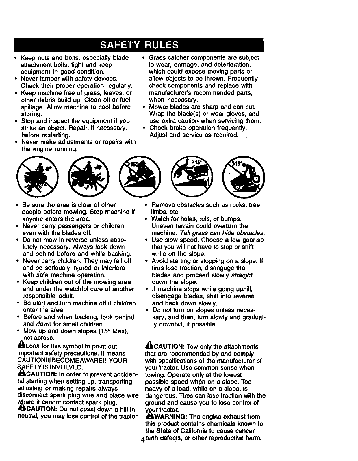
• Mow up and down slopes (15 ° Max),
not across.
'ALook for this symbol to point out
important safety precautions. It means
CAUTION!H BECOMEAWAREI!! YOUR
_FETY IS INVOLVED.
CAUTION. In order to prevent acciden-
tal starting when setting up, transporting,
adjusting or making repairs always
disconnect spark plug wire and place wire
_re it cannot contact spark plug.
AUTION. Do not coast down a hill in
neutral, you may lose control of the tractor.
• Remove obstacles such as rocks, tree
limbs, etc.
• Watch for holes, ruts, or bumps.
Uneven terrain could overturn the
machine. Tall grass can hide obstacles.
• Use slow speed. Choose a low gear,so
that you will not have to stop or shift
while on the slope.
• Avoid starting or stopping on a slope. If
tires lose traction, disengage the
blades and proceed slowly straight
down the slope.
• If machine stops while going uphill,
disengage blades, shift into reverse
and back down slowly.
• Do notturn on slopes unless neces-
sary, and then, turn slowly and gradual-
ly downhill, if possible.
_CAUTION: Tow only the attachments
that are recommended by and comply
with specifications of the manufacturer of
your tractor. Use common sense when
towing. Operate only at the lowest
possible speed when on a slope.Too
heavy of a load, while on a slope, is
dangerous. Tires can lose traction with the
ground and cause you to lose control of
_r tractor.
WARNING: The engine exhaust from
this product contains chemicals known to
the State of California to cause cancer,
4birth defects, or other reproductive harm.
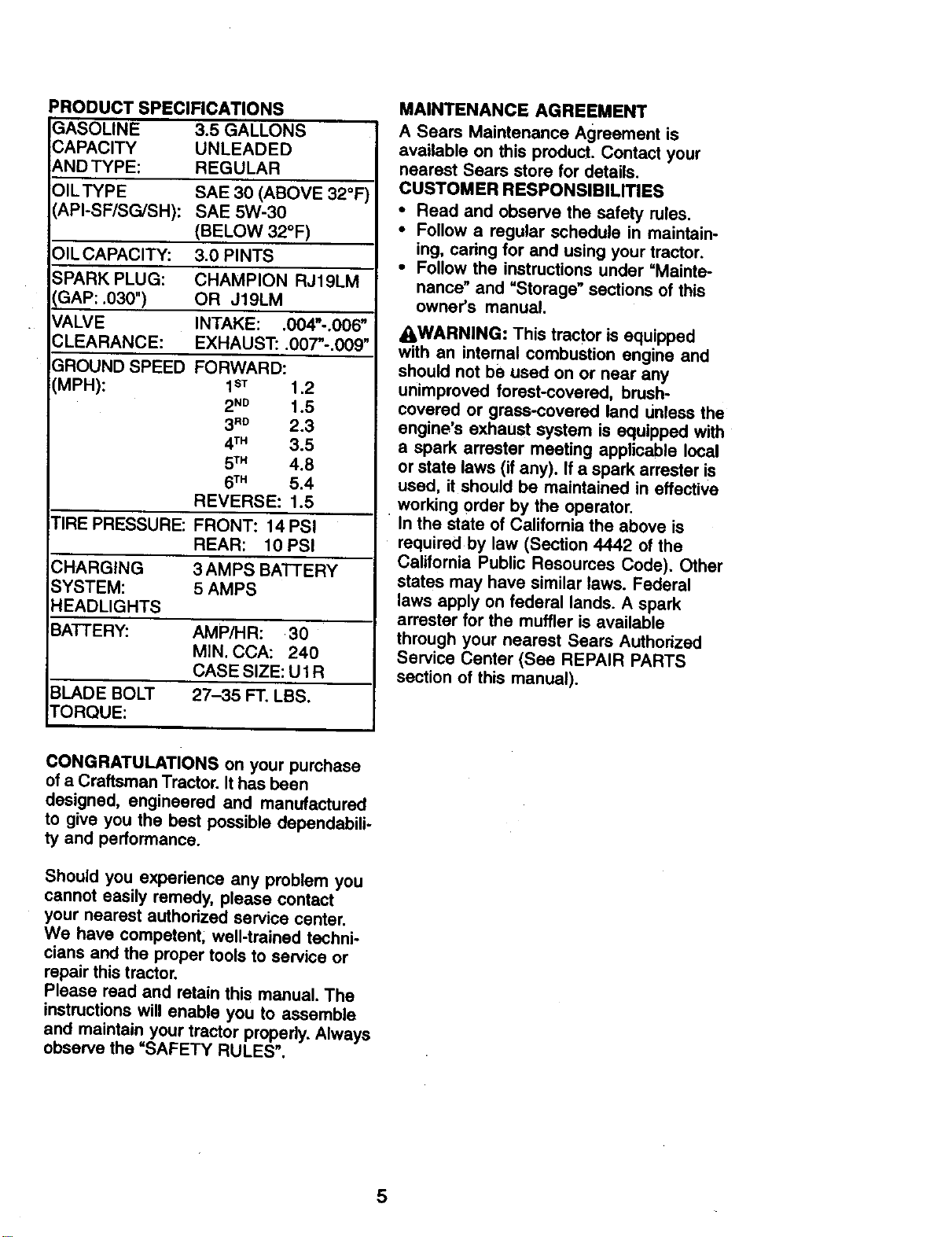
PRODUCTSPECIFICATIONS
GASOLINE 3.5GALLONS
CAPACITY UNLEADED
ANDTYPE: REGULAR
OILTYPE SAE 30 (ABOVE 32°F
(API-SF/SG/SH): SAE 5W-30
(BELOW 32°F)
OILCAPACITY: 3.0 PINTS
SPARK PLUG: CHAMPION RJ19LM
GAP: .030") OR J19LM
VALVE INTAKE: .004"-.006"
CLEARANCE: EXHAUST: .007"-.009"
GROUND SPEED FORWARD:
(MPH): 1sT 1.2
2 "D 1.5
3"D 2.3
4TM 3.5
5TM 4.8
6TM 5.4
REVERSE: 1.5
TIRE PRESSURE: FRONT: 14 PSI
REAR: 10 PSI
CHARGING 3 AMPS BATTERY
SYSTEM: 5 AMPS
HEADLIGHTS
BATTERY." AMP/HR: 30
MIN. CCA: 240
CASE SIZE: U1R
BLADE BOLT 27-35 FT. LBS.
tORQUE:
MAINTENANCE AGREEMENT
A Sears Maintenance Agreement is
available on this product. Contact your
nearest Sears store for details.
CUSTOMER RESPONSIBILITIES
• Read and observe the safety rules.
• Follow a regular schedule in maintain-
ing, caring for and using your tractor.
• Follow the instructions under =Mainte-
nance" and "Storage" sections of this
owner's manual.
_WARNING: This tractor is equipped
with an intemal combustion engine and
should not be used on or near any
unimproved forest-covered, brush-
covered or grass-covered land unless the
engine's exhaust system is equipped with
a spark arrester meeting applicable local
or state laws (if any). If a spark arrester is
used, it should be maintained in effective
working order by the operator.
In the state of California the above is
required by law (Section 4442 of the
California Public Resoumes Code). Other
states may have similar laws. Federal
laws apply on federal lands. A spark
arrester for the muffler is available
through your nearest Sears Authorized
Service Center (See REPAIR PARTS
section of this manual).
CONGRATULATIONS on your purchase
of a Craftsman Tractor. It has been
designed, engineered and manufactured
to give you the best possible dependabili-
ty and performance.
Should you experience any problem you
cannot easily remedy, please contact
your nearest authodzed service center.
We have competent; well-trained techni-
cians and the proper tools to service or
repair this tractor.
Please read and retain this manual. The
instructions will enable you to assemble
and maintain your tractor properly. Always
observe the "SAFETY RULES".
5
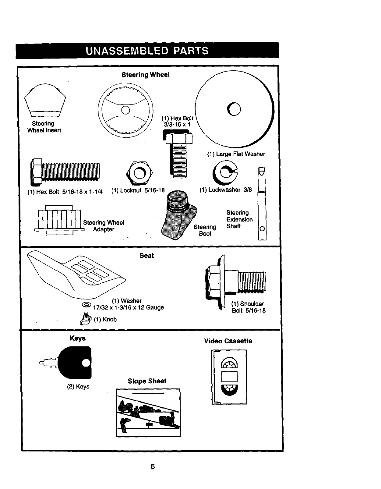
Steering
Wheel Insert
Steering Wheel
(1) Hex Bolt 5/16-18 x 1-1/4
@
(1) Locknut 5/16-18
, _ Stee/_idngpWheel
L J
O
(1) Large
Flat Washer
(1) Lockwasher 3/8
Steering
Extension
Steering Shaft 0
Boot
Seat
(1) Washer
17/32 x 1-3/16 x 12 Gauge
_(1) Knob
Keys
(2) Keys
Slope Sheet
(1) Shoulder
Bolt 5115-18
Video Cassette
6
Your new tractor has been assembled at the factory with exception of those parts left
unassembled for shipping purposes. To ensure safe and proper operation of your
tractor all parts and hardware you assemble must be tightened securely. Use the
correct tools as necessary to insure proper tightness. Review the video cassette before
you begin.
TOOLS REQUIRED FOR ASSEMBLY • Assemble large flat washer, 3/8 lock
A socket wrench set will make assembly • washer, 3/8 hex bolt and tighten
easier. Standard wrench sizes you need : securely.
are listed below. . • Snap steering wheel insert into center
(1) 9/16" wrench (2} 1/2 wrench of steering wheel.
(1) Utility knife (1) Pliers • Remove protective materials from
tractor hood and grill.
IMPORTANT: Check for and remove any
staples in skid that may puncture tires
where tractor isto roll off skid.
(1)3/4" socket with (1) Tire pressure
drive ratchet gauge
When rightor left hand is mentioned in
this manual, it means, from your point of
view, when you are in the operating
position (seated behind the steering
wheel).
TO REMOVE TRACTOR FROM
CARTON
UNPACK CARTON
• Remove all accessible loose parts and
parts boxes from shipping carton.
• Cut, trom top to bottom, a!ong lines on
all four comers of shipping carton, and
lay panels flat.
• Check for any additional loose parts or
boxes and remove.
BEFORE REMOVING TRACTOR
FROM SKID
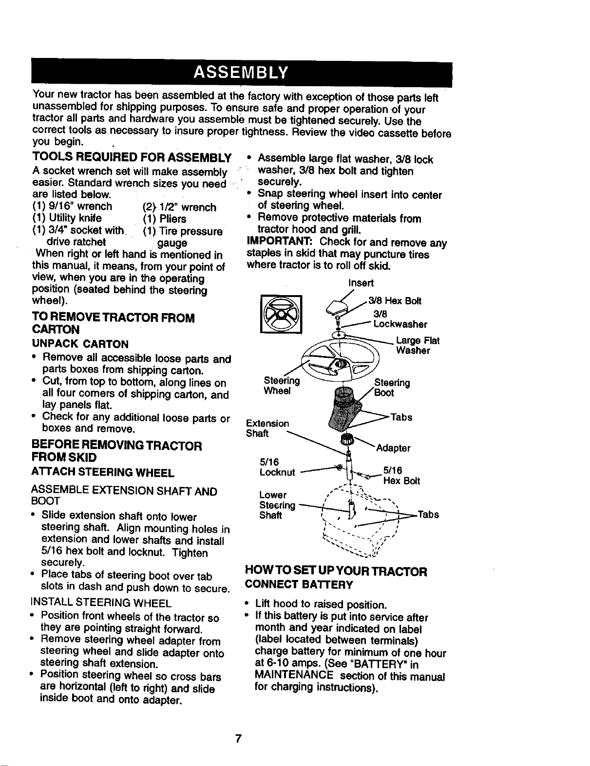
ATTACH STEERING WHEEL
Insert
_,._ Lockwasher
_ Large Flat
w..r
Steedng _ _'_::_----"/Steering
Wheel _'Boot
_Adaptsr
5116
Extension
Shaft
5/16
Locknut
ASSEMBLE EXTENSION SHAFT AND
BOOT
• Slide extension shaft onto lower
steering shaft. Align mounting holes in
extension and lower shafts and install
5/16 hex bolt and Iocknut. Tighten
securely.
• Place tabs of steering boot over tab
slots in dash and push down to secure.
INSTALL STEERING WHEEL
• Position front wheels of the tractor so
they are pointing straight forward.
• Remove steering wheel adapter from
steering wheel and slide adapter onto
steering shaft extension.
• Position steering wheel so cross bars
are horizontal (left to right) and slide
inside boot and onto adapter.
HOW TO SET UP YOUR TRACTOR
CONNECT BATTERY
Lift hood to raised position.
If this battery is put into service after
month and year indicated on label
(label located between terminals)
charge battery for minimum of one hour
at 6-10 amps. (See "BA'F_'ERY" in
MAINTENANCE section of this manual
for charging instructions).
7
°,., ...:,s ." "ZJ.,
tJ_ o
Label
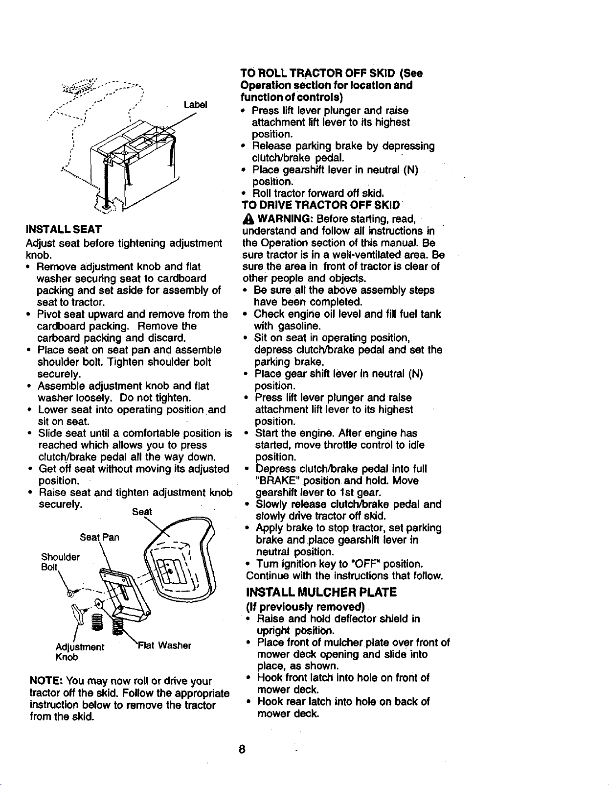
INSTALL SEAT
Adjust seat before tightening adjustment
knob.
• Remove adjustment knob and fiat
washer securing seat to cardboard
packing and set aside for assembly of
seat to tractor.
• Pivot seat upward and remove from the
cardboard packing. Remove the
carboard packing and discard.
• Place seat on seat pan and assemble
shoulder bolt. Tighten shoulder bo_t
securely.
• Assemble adjustment knob and flat
washer loosely. Do not tighten.
• Lower seat into operating position and
sit on seat.
• Slide seat until a comfortable position is
reached which allows you to press
clutch/brake pedal all the way down.
• Get off seat without moving its adjusted
position.
• Raise seat and tighten adjustment knob
securely. Seat
Seat Pan
Bolt
Adjustment lat Washer
Knob
NOTE: You may now roll or drive your
tractor oft the skid. Follow the appropriate
instruction below to remove the tractor
from the skid.
TO ROLL TRACTOR OFF SKID (See
Operation section for location and
function of controls)
• Press lift lever plunger and raise
attachment lift lever to its highest
position.
• Release parking brake by depressing
clutch/brake pedal.
• Place gearshift lever in neutral (N)
position.
• Roll tractor forward off skid.
TO DRIVE TRACTOR OFF SKID
WARNING: Before starting, read,
understand and follow all instructions in
the Operation section of this manual. Be
sure tractor is in a well-ventilated area. Be
sure the area in front of tractor is clear of
other people and objects.
• Be sure all the above assembly steps
have been completed.
• Check engine oil level and fill fuel tank
with gasoline,
• Sit on seat in operating position,
depress clutch/brake pedal and set the
parking brake,
• Place gear shift lever in neutral (N)
position,
• Press lift lever plunger and raise
attachment lift lever to its highest
position.
• Start the engine. After engine has
started, move throttle control to idle
position.
• Depress clutch/brake pedal into full
"BRAKE" position and hold. Move
gearshift lever to 1st gear.
• Slowly release clutch/brake pedal and
slowly drive tractor off skid.
• Apply brake to stop tractor, set parking
brake and place gearshift lever in
neutral position.
•Tum ignition key to "OFF" position.
Continue with the instructions that follow.
INSTALL MULCHER PLATE
(If previously removed)
• Raise and hold deflector shield in
upright position.
• Place front of muloher plate over front of
mower deck opening and slide into
place, as shown•
° Hook front latch into hole on front of
mower deck,
° Hook rear latch into hole on back of
mower deck.'
8
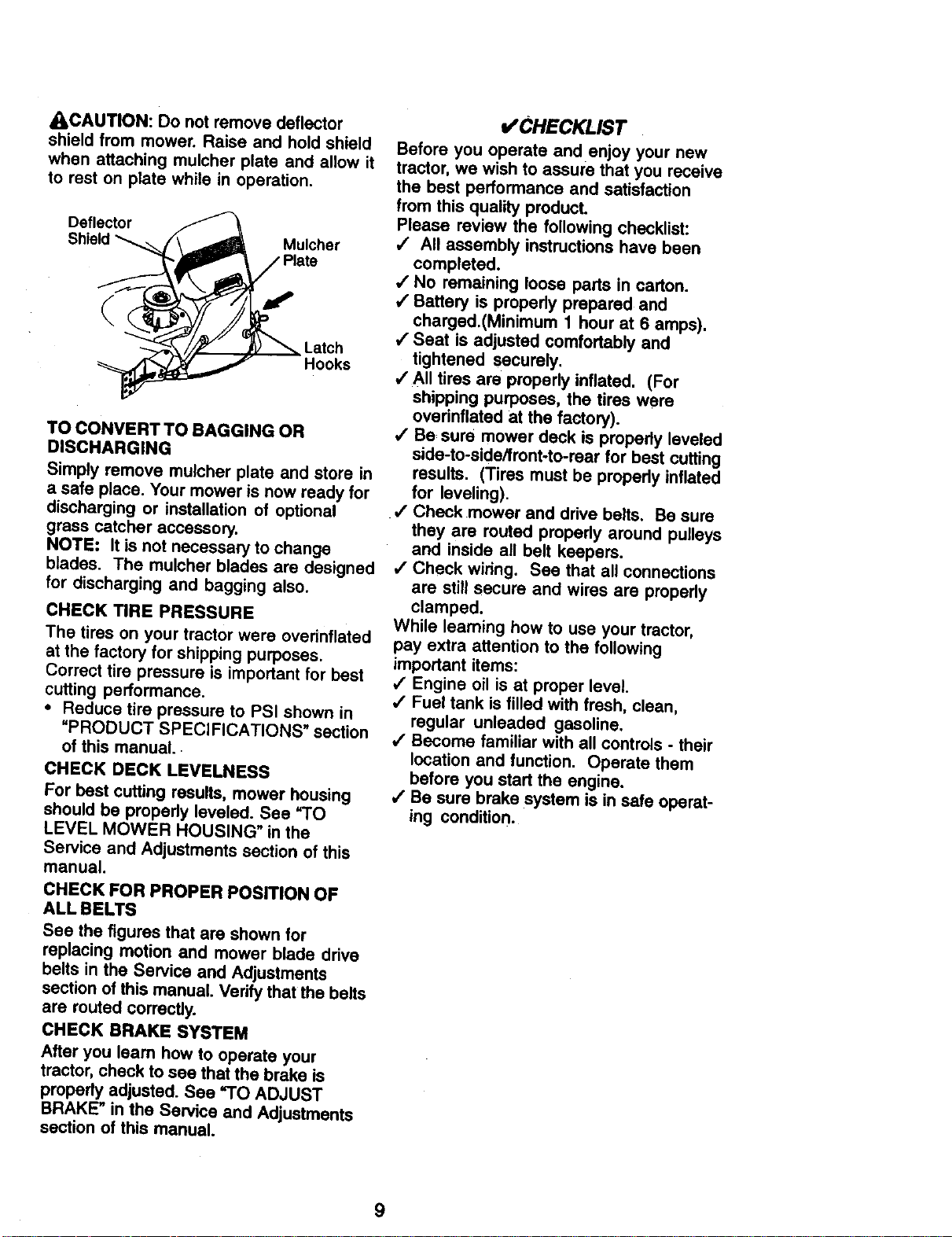
ACAUTION: Do not remove deflector
shield from mower. Raise and hold shield
when attaching mulcher plate and allow it
to rest on plate while in operation.
TO CONVERT TO BAGGING OR
DISCHARGING
Simply remove mulcher plate and store in
a safe place. Your mower is now ready for
discharging or installation of optional
grass catcher accessory.
NOTE: It is not necessary to change
blades. The mulcher blades are designed
for discharging and bagging also.
CHECK TIRE PRESSURE
The tires on your tractor were overinflated
at the factory for shipping purposes.
Correct tire pressure is important for best
cutting performance.
• Reduce tire pressure to PSI shown in
=PRODUCT SPECIFICATIONS" section
of this manual.
CHECK DECK LEVELNESS
For best cutting results, mower housing
should be propedy leveled. See =TO
LEVEL MOWER HOUSING" in the
Service and Adjustments section of this
manual.
CHECK FOR PROPER POSITION OF
ALL BELTS
See the figures that are shown for
replacing motion and mower blade drive
belts in the Service and Adjustments
section of this manual. Verify that the belts
are routed correctly.
CHECK BRAKE SYSTEM
After you learn how to operate your
tractor, check to sea that the brake is
properly adjusted. See "TO ADJUST
BRAKE" in the Service and Adjustments
section of this manual.
I/CHECKLIST
Before you operate and enjoy your new
tractor, we wish to assure that you receive
the best performance and satisfaction
from this quality product.
Please review the following checklist:
,/ All assembly instructions have been
completed.
/ No remaining loose parts in carton.
,/Battery is properly prepared and
charged.(Minimum 1 hour at 6 amps).
,/Seat is adjusted comfortably and
tightened securely.
•/All tires are properly inflated. (For
shipping purposes, the tires were
overinflated at the factory).
,/Be sure mower deck is propedy leveled
side-to-side/front-to-rear for best cutting
results. (Tires must be propedy inflated
for leveling).
,/Check mower and drive belts. Be sure
they are routed properly around pulleys
and inside all belt keepers.
,/Check wiring. See that all connections
are still secure and wires are propedy
clamped.
While learning how to use your tractor,
pay extra attention to the following
important items:
/ Engine oil is at proper level.
•/ Fuel tank is filled with fresh, clean,
regular unleaded gasoline.
,/Become familiar with all controls - their
location and function. Operate them
before you start the engine.
,/Be sure brake system is in safe operat-
ing condition.
9
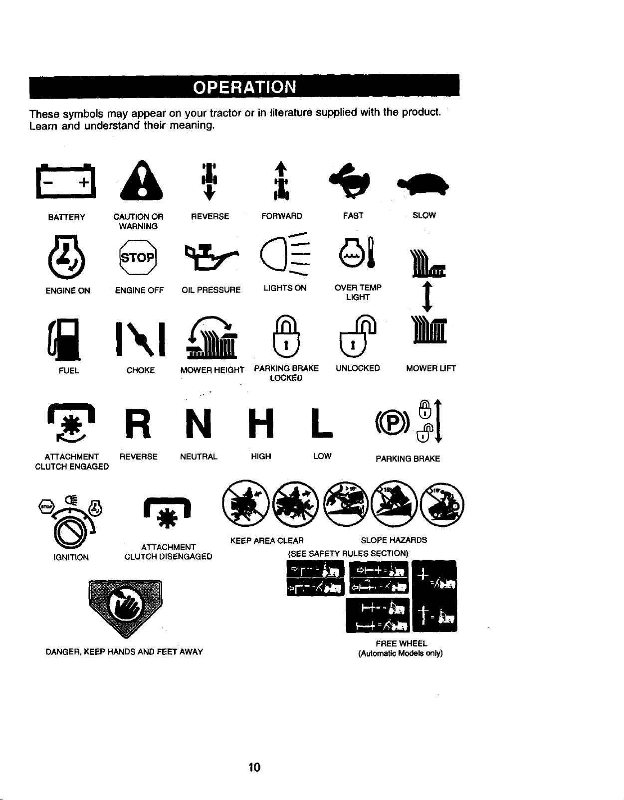
These symbols may appear on your tractor or in literature supplied with the product.
Learn and understand their meaning.
BATTERY CAUTION OR REVERSE FORWARD FAST SLOW
WARNING
ENGINE ON ENGINE OFF OIL PRESSURE LIGHTS ON OVER TEMP
LIGHT
FUEL CHOKE MOWER HEIGHT PARKING BRAKE UNLOCKED MOWER LIFT
LOCKED
R N H L
ATrACHMENT REVERSE NEUTRAL HIGH
CLUTCH ENGAGED
LOW
PARKING BRAKE
KEEP AREA CLEAR SLOPE HAZARDS
ATTACHMENT
IGNITION CLUTCH DISENGAGED
DANGER, KEEP HANDS AND FEET AWAY
(SEE SAFETY RULES SECTION)
FREE WHEEL
(AutomaticModelsonly)
10
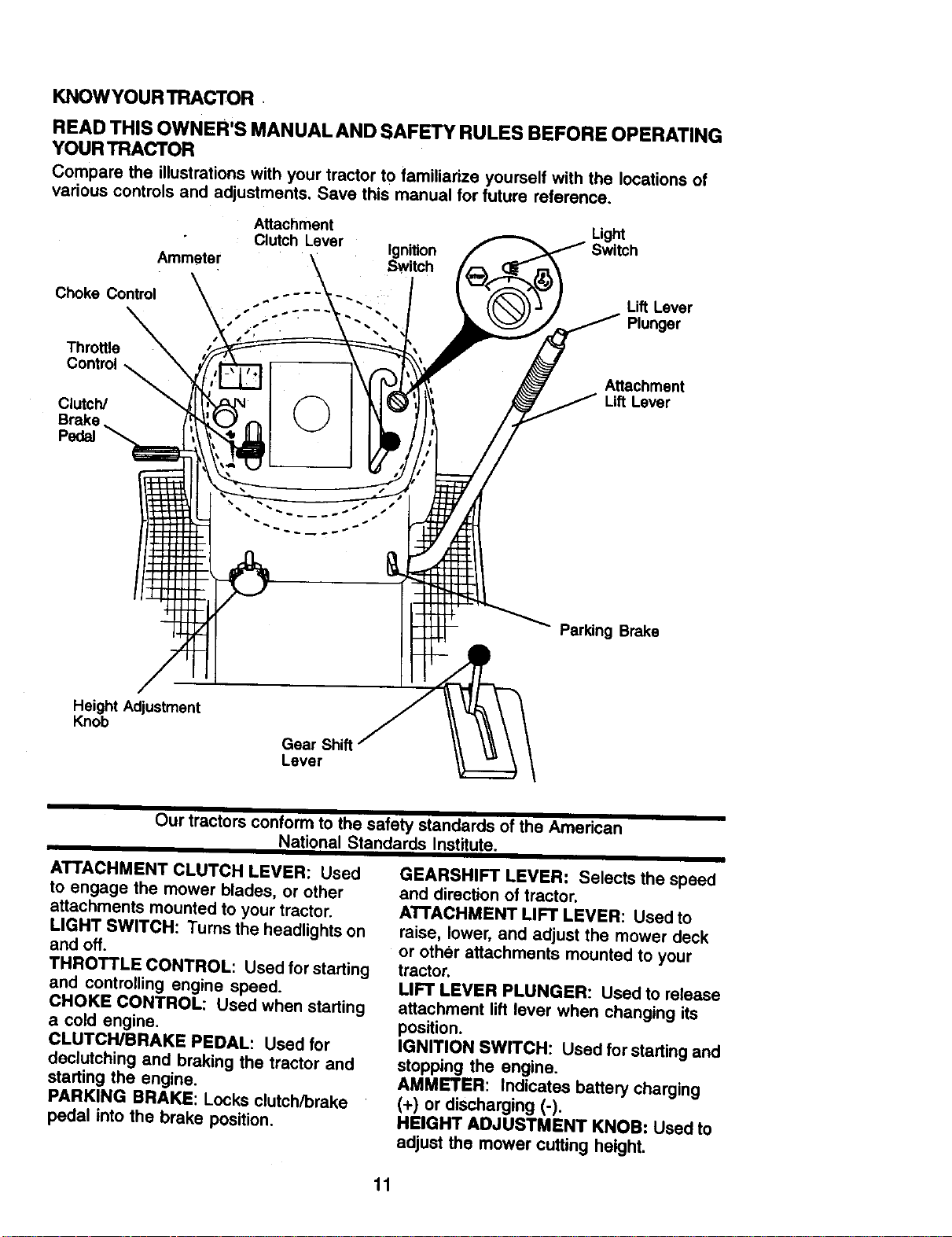
KNOWYOUR TRACTOR
READ THIS OWNER'S MANUAL AND SAFETY RULES BEFORE OPERATING
YOURTRACTOR
Compare the illustrationswith your tractor to familiarize yourself with the locations of
various controls and adjustments. Save this manual for future reference.
Attachment Light
Clutch Lever Ignition Switch
Ammeter SWtch
Choke Control
Lift Lever
Plunger
Throttle
Control_
Clutch/
Brake
Pedal
Attachment
Lift Lever
Parking Brake
Height Adjustment
Knob
Gear Shift
Lever
Our tractors conform to the safety standards of the American
National Standards Institute.
ATTACHMENT CLUTCH LEVER: Used
to engage the mower blades, or other
attachments mounted to your tractor.
LIGHT SWITCH: Turns the headlights on
and off.
THROTTLE CONTROL: Used for starting
and controlling engine speed.
CHOKE CONTROL: Used when starting
a cold engine.
CLUTCH/BRAKE PEDAL: Used for
declutching and braking the tractor and
starting the engine.
PARKING BRAKE: Locks clutch[orake
pedal into the brake position.
GEARSHIFT LEVER: Selects the speed
and direction of tractor.
ATTACHMENT LIFT LEVER: Used to
raise, lower, and adjust the mower deck
or other attachments mounted to your
tractor.
LIFT LEVER PLUNGER: Used to release
attachment lift lever when changing its
position.
IGNITION SWITCH: Used for starting and
stopping the engine.
AMMETER: Indicates battery charging
(+) or discharging (-).
HEIGHT ADJUSTMENT KNOB: Used to
adjust the mower cutting height.
11
The operation of any tractor can result in foreign objects thrown into the
eyes, which can result in severe eye damage. Always wear safety
glasses or eye shields while operating your tractor or performing any
adjustments or repairs. We recommend a wide vision safety mask over
spectacles, or standard safety glasses.
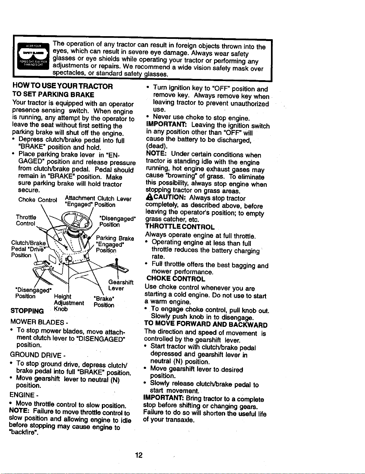
HOW TO USE YOUR TRACTOR
TO SET PARKING BRAKE
Your tractor is equipped with an operator
presence sensing switch. When engine
is running, any attempt by the operator to
leave the seat without first setting the
parking brake will shut off the engine.
• Depress clutch/brake pedal into full
=BRAKE" position and hold.
• Place parking brake lever in =EN-
GAGED" position and release pressure
from clutch/brake pedal. Pedal should
remain in =BRAKE" position. Make
sure parking brake will hold tractor
secure.
Choke Control Attachment Clutch Lever
"Engaged" Position
Throttle "Disengaged"
Control Position
Parking Brake
Clutch/Brake "Engaged'
Position
Position
"Disengaged'
Position Height
Adjustment
STOPPING Knob
MOWER BLADES -
Gearshift
Lever
"Brake"
Position
• To stop mower blades, move attach-
ment clutch lever to =DISENGAGED"
position.
GROUND DRIVE -
• To stop ground drive, depress clutch/
brake pedal into full =BRAKE" position,
• Move gearshift lever to neutral (N)
position.
ENGINE -
• Move throttle control to slow position.
NOTE: Failure to move throttle control to
slow position and allowing engine to idle
before stopping may cause engine to
=backfire".
• Turn ignition key to "OFF" position and
remove key. Always remove key when
leaving tractor to prevent unauthorized
use.
• Never use choke to stop engine.
IMPORTANT: Leaving the ignition switch
in any position other than =OFF" will
cause the battery to be discharged,
(dead).
NOTE: Under certain conditions when
tractor is standing idle with the engine
running, hot engine exhaust gases may
cause =browning" of grass. To eliminate
this possibility,always stop engine when
stopping tractor on grass areas.
_CAUTION: Always stop tractor
completely, as described above, before
leaving the operator's position;to empty
grass catcher, etc.
THROTTLE CONTROL .
Always operate engine at full throttle.
• Operating engine at less than full
throttle reduces the battery charging
rate.
• Full throttle offers the best bagging and
mower performance.
CHOKE CONTROL
Use choke control whenever you are
starting a cold engine. Do not use to start
a warm engine.
• To engage choke control, pull knob out.
Slowly push knob in to disengage.
TO MOVE FORWARD AND BACKWARD
The direction and speed of movement is
controlled by the gearshift lever.
• Start tractor with clutch/brake pedal
depressed and gearshift lever in
neutral (N) position.
• Move gearshift lever to desired
position.
• Slowly release clutch/brake pedal to
start movement.
IMPORTANT: Bdng tractor to a complete
stop before shifting or changing gears.
Failure to do so will shorten the useful life
of you_"transaxle.
12
TOADJUSTMOWER CUTrlNG HEIGHT
The cutting height is controlled by turning
the height adjustment knob in desired direc-
tion.
• Tum knob clockwise (_) to raise cut-
ting height.
• Tum knob counterclockwise (1'-_) to
lower cutting height.
The cuttingheight range isapproximately 1-
• 1/2" to 4-1/2". The heights are measured
from the ground to the blade tip with the
engine not running. These heights are ap-
proximate and may vary depending upon
soilconditions, height of grass and types of
grass being mowed.
The average lawn should be cut to
approximately 2-1/2 inches during the
cool season and to over 3 inches during
hot months. For healthier and better
looking lawns, mow often and after
moderate growth.
For best cutting performance, grass
over 6 inches in height should be mowed
twice. Make the first cut relatively high;
the second to desired height.
TO ADJUST GAUGE WHEELS
Gauge wheels are properly adjusted
when they are slightly off the ground
when mower is at the desired cutting
height in operating position. Gauge
wheels then keep the deck in proper
position to help prevent scalping in most
terrain conditions.
• Adjust gauge wheels with tractor on a
flat level surface.
• Adjust mower to desired cutting height
(See =TO ADJUST MOWER CUTTING
HEIGHT" in the Operation section of this
manual).
• With mower in desired height of cut
position, gauge wheels should be
assembled so they are slightly off the
ground. Install gauge wheel in appro-
priate hole with shoulder bolt, 318
washer, and 3/8-16 Iocknut and tighten
securely.
• Repeat for opposite side installing
gauge wheel in same adjustment hole.
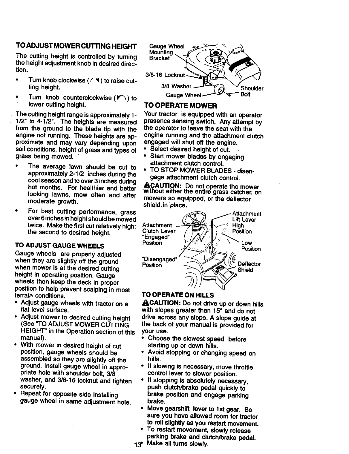
Gauge Wheel "_
Bracket
3/8-16 Locknut -
3/8 Washer ShoUlder
Gauge Whee
TO OPERATE MOWER
Your tractor is equipped with an operator
presence sensing switch. Any attempt by
the operator to leave the seat with the
engine running and the attachment dutch
engaged will shut off the engine.
• Select desired height of cut.
• Start mower blades by engaging
attachment clutch control.
• TO STOP MOWER BLADES - disen-
gage attachment clutch control.
&CAUTION: De not operate the mower
without either the entire grass catcher, on
mowers so equipped, or the deflector
shield in place.
A_achment
Clutch Lever
=Engaged"
PosiUon
Lift Lever
High
Position
Low
Po_on
Position
Deflector
TO OPERATE ON HILLS
_CAUTION: Do not drive up or down hills
with slopes greater than 15° and do not
drive across any slope. A slope guide at
the back of your manual is provided for
your use.
• Choose the slowest speed before
starting up or down hills.
• Avoid stopping or changing speed on
hills.
• If slowing is necessary, move throttle
control lever to slower position.
• If stopping is absolutely necessary,
push clutchJbrake pedal quickly to
brake position and engage parking
brake.
• Mevegearshift leverto lstgear. Be
sure you have allowed room for tractor
to roll slightly as you restart movement.
• To restart movement, slowly release
parking brake and clutch/brake pedal.
13' Make all turns slowly.
TO TRANSPORT
• Raise attachment lift to highest position
with attachment lift control.
• When pushing or towing your tractor,
be sure gearshift lever is in neutral (N)
position.
• Do not push or tow tractor at more than
five (5) MPH.
NOTE: To protect hood from damage
when transporting your tractor on a truck
or a trailer, be sure hood is closed and
secured to tractor. Use an appropriate
means of tying hood to tractor (rope, cord,
etc.).
TOWING CARTS AND OTHER
ATTACHMENTS
Tow only the attachments that are
recommended by and comply with
specifications of the manufacturer of your
tractor.Use common sense when towing.
Too heavy of a load, while on a slope, is
dangerous. Tires can lose traction with
the ground and cause you to lose control
ofyour tractor.
BEFORE STARTING THE ENGINE
CHECK ENGINE OIL LEVEL
• The engine in your tractor has been
shipped, from the factory, already filled
with summer weight oil.
• Check engine oil with tractor on level
ground.
• Remove oil fill cap/dipstick and wipe
clean, reinsert the dipstick and screw
cap tight, wait for a few seconds,
remove and read oil level. If neces-
sary, add oil until "FULL" mark on
dipstick is reached. Do not overfill.
• For cold weather operation you should
change oil for easier starting (See "OIL
VISCOSITY CHART" in the Mainten-
ance section of this manual).
• To change engine oil, see the Mainten-
ance section in this manual.
ADDGASOLINE
• Fill fuel tank. Use fresh, clean, regular
unleaded gasoline with a minimum of
87 octane. (Use of leaded gasoline will
increase carbon and lead oxide
deposits and reduce valve life). Do not
mix oil with gasoline. Purchase fuel in
quantities that can be used within 30
days to assure fuel freshness.
IMPORTANT: When operating in tem-
peratures below 32°F(0°C), use fresh,
clean winter grade gasoline to help
insure good cold weather starting.
_WARNING: Experience indicates that
alcohol blended fuels (called gasohol or
using ethanol or methanol) can attract
moisture which leads to separation and
formation of acids during storage. Acidic
gas can damage the fuel system of an
engine while in storage. To avoid engine
problems, the fuel system should be
emptied before storage of 30 days or
longer. Drain the gas tank, start the
engine and let it run until the fuel lines
and carburetor are empty. Use fresh fuel
next season. See Storage Instructions for
additional information. Never use engine
or carburetor cleaner products in the fuel
tank or permanent damage may occur.
4C),CAUTION: Fill to bottom of gas tank
filler neck. Do not overfill. Wipe off any
spilled oil or fuel. Do not store, spill or use
gasoline near an open flame.
14
TO START ENGINE
When starting the engine for the first time
or if the engine has run out of fuel, it will
take extra cranking time to move fuel from
the tank to the engine.
• Sit on seat in operating position,
depress clutch/brake pedal and set
parking brake.
• Place gear shift lever in neutral (N)
position.
• Move attachment clutch to =DISEN-
GAGED" position;
• Move throttle control to fast position
• Pull choke control out for a cold engine
start attempt: For a warm engine start
attempt the choke control may not be
needed.
NOTE: Before starting, read the warm and
cold starting procedures below.
• insert key into ignition and turn key
clockwise to =START" position and
release key as soon as engine starts.
Do not run starter continuously for more
than fifteen seconds per minute, if the
engine does not start after several
attempts, push choke control in, wait a
few minutes and try again. If engine still
does not start, pull the choke control
out and retry.
WARM WEATHER STARTING (50 ° F AND
ABOVE)
• When engine starts, slowly push choke
control in until the engine begins to run
smoothly. If the engine starts to run
roughly, pull the choke control out
slightly for a few seconds and then
continue to push the control in slowly.
• The attachments and ground drive can
now be used. If the engine does not
accept the load, restart the engine and
allow it to warm up for one minute
using the choke as described above.
COLD WEATHER STARTING (50 ° FAND
BELOW)
• When engine starts, slowly push choke
control in until the engine begins to run
smoothly. Continue to push the choke
control in small steps allowing the
engine to accept small changes in
speed and load, until the choke control
is fully in. If the engine starts to run
• roughly, pull the choke control out
slightly for a few seconds and then
continue to push the control in slowly.
This may require an engine warm-up
period from several seconds to several
minutes, depending on the tempera-
ture,
• The attachments can be used during
the engine warm-up period and may
require the choke control be pulled out
slightly,
NOTE: A high altitude (above 3000 feet)
or in cold temperatures (below 32 F) the
carburetor fuel mixture may need to be
adjusted for best engine performance.
See _'O ADJUST CARBURETOR" in the
Service and Adjustments section of this
manual.
15
MOWING TIPS
• Mower should be properly leveled for
best mowing pedormanoe. See =TO
LEVEL MOWER HOUSING" in the
Service and Adjustments section of this
manual,
• The left hand side of mower should be
used for trimming.
• Drive so that clippings are discharged
onto the area that has been cut. Have
the cut area to the right of the machine.
This will result in a more even distribu-
tion of clippings and more uniform
cutting.
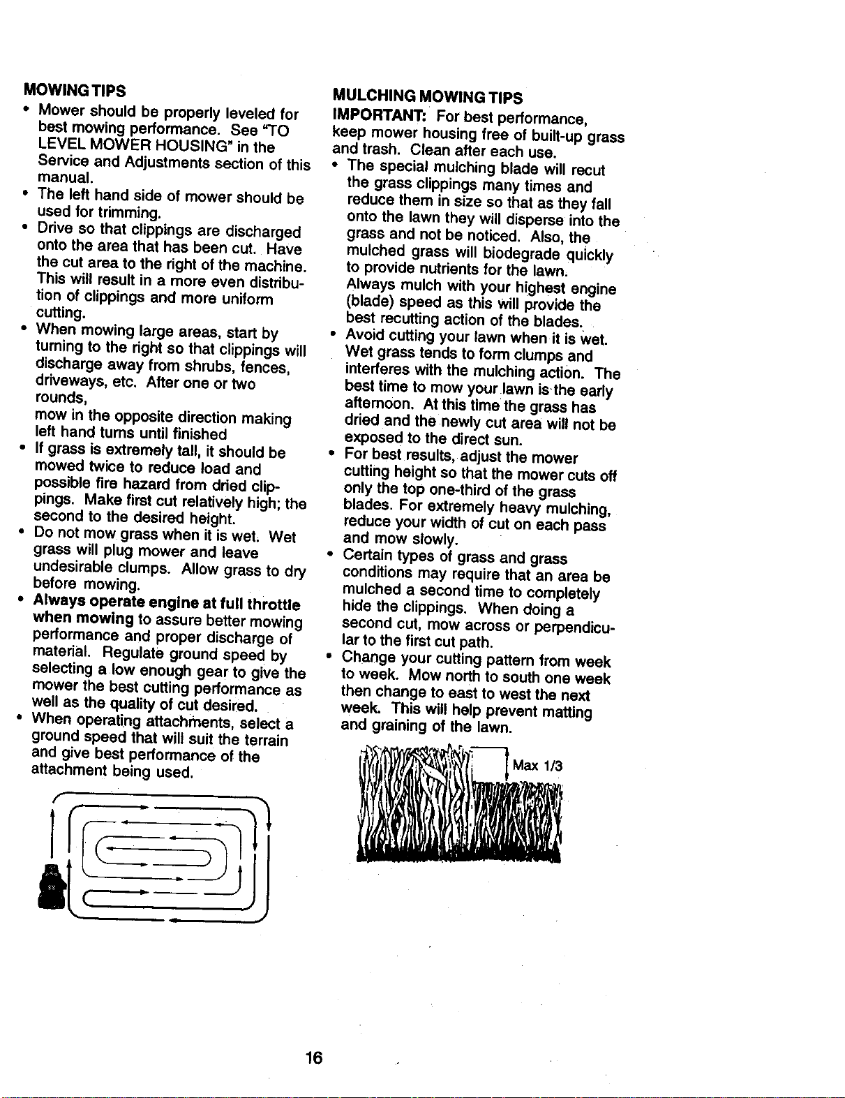
• When mowing large areas, start by
turning to the right so that clippings will
discharge away from shrubs, fences,
driveways, etc. After one or two
rounds,
mow in the opposite direction making
left hand turns until finished
• If grass is extremely tall, it should be
mowed twice to reduce load and
possible fire hazard from dried cUp-
pings. Make first cut relatively high; the
second to the desired height.
• Do not mow grass when it is wet, Wet
grass will plug mower and leave
undesirable clumps. Allow grass to dry
before mowing,
• Always operate engine at full throttle
when mowing to assure better mowing
performance and proper discharge of
material. Regulate ground speed by
selecting a low enough gear to give the
mower the best cutting performance as
well as the quality of cut desired.
• When operating attachments, select a
ground speed that will suit the terrain
and give best performance of the
attachment being used.
,/
MULCHING MOWING TIPS
IMPORTANT: For best performance,
keep mower housing free of built-up grass
and trash. Clean after each use.
• The special mulching blade will recut
the grass clippings many times and
reduce them in size so that as they fall
onto the lawn they will disperse into the
grass and not be noticed. Also, the
mulched grass will biodegrade quickly
to provide nutrients for the lawn,
Always mulch with your highest engine
(blade) speed as this Willprovide the
best recutting action of the blades.
• Avoid cutting your lawn when it is wet.
Wet grass tends to form clumps and
interferes with the mulching action. The
best time to mow your lawn isthe early
aftemoon. At this time the grass has
dried and the newly cut area will not be
exposed to the direct sun.
• For best results, adjust the mower
cutting height so that the mower cuts off
only the top one-third of the grass
blades. For extremely heavy mulching,
reduce your width of cut on each pass
and mow slowly.
• Certain types of grass and grass
conditions may require that an area be
mulched a second time to completely
hide the clippings. When doing a
second cut, mow across or perpendicu-
larto the first cut path.
• Change your cutting pattern from week
to week. Mow north to south one week
then change to east to west the next
week. This will help prevent matting
and graining of the lawn.
16
REGULARSERVICE I/_9"_/_ _" _,_/€_/O_/_,_/_P_ SERVICE....... DATES
C_eckBrakeOpera,on If
Ch=*_,, e,,==, l/
Chec_ OperMor prlmer_ and
T Int*rk_ Symn_ I_
R C_k fo_Loo.F==.,_ I/, V'
_lpen/Replace Mo.r Btadu
0 ct_ckBa_fyLeve_
R cke._t_ry_ Terminals _fP
C_ck Tn_iax_ Cooling V e ;
AdJustBlade Belt(e) Tenslon
AdjustMoUonDriveBelt(s)Teflon
CtteckEnglrmOil Level
ChangeEngineCh
E Qun AixFilter
N oean Air Screen
Inspect Muffler/Span_ Attester
ReplAceOil R;ter(if eq_Roed)
ReplaceSparkPlug
Replace Fuel Filt_ V _
I - Ct'_91, mo_ _n VW._t_opw_9 ,.'ndm I_t',_m_yto_d ot b_t'_ aralb,ts_ t_. S - _I_lUlPl_d w11hl_tb_ l_m.
2 - .So.ice more o_n wh_ q>Imllng In 61tryor dulty c_lUo_, e - Not recMred If equ_ped withmalnlenanc_me ba_e_,y.
3 - # eq_ w_thcBtibet, chang_ o_twe:y 50 hours, ? - TigMen h'o_ exle plvo_bol_to 35 fL-Ibs, m_kxlum,
4 - Re_ blades rnom oP,en when mowing Inssr_ly m_l. DO not ov(_llgh_n.
v' v'
v'
GENERAL RECOMMENDATIONS
The warranty on this tractor does not
cover items that have been subjected to
operator abuse or negligence. To receive
full value from the warranty, operator must
maintain tractor as instructed in this
manual.
Some adjustments will need to be made
periodically to properly maintain your
tractor.
Air adjustments in the Service and
Adjustments section of this manual should
be checked at least once each season.
• Once a year you should replace the
spark plug, clean or replace air filter,
and check blades and belts for wear, A
new spark plug and clean air filter
assure proper air-fuel mixture and help
your engine run better and last longer.
BEFORE EACH USE
• Check engine oil level.
• Check brake operation.
• Check tire pressure.
• Check operator presence and interlock
systems for proper operation.
• Check for loose fasteners.
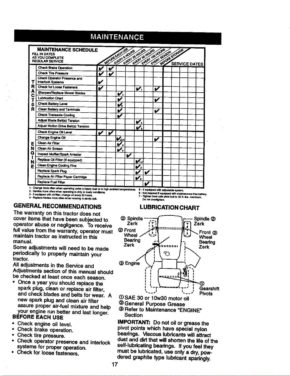
LUBRICATION CHART
(_) Spindle
Zerk Zerk
(_) Front
Wheel Wheel
Bearing Bearing
Zerk Zerk
(_) Engine
I I
1--_' I
_SAE 30 or 10w30 motor oil
_) General Purpose Grease
® Refer to Maintenance =ENGINE"
Section
IMPORTANT: Do not oil or grease the
pivot points which have special nylon
bearings. Viscous lubricants will attract
dust and dirt that will shorten the life of the
self-lubricating bearings. Ifyou feel they
must be lubricated, use only a dry, pow-
dered graphite type lubricant sparingly.
Gearshift
Pivots
17
1RACI-OH
Always observe safety rules when
performing any maintenance.
BRAKE OPERATION
If tractor requires more than six (6) feet
stopping distance at high speed in
highest gear, then brake must be ad-
justed. (See =TO ADJUST BRAKE" in the
Service and Adjustments section of this
manual).
TIRES
• Maintain proper air pressure in all tires
(See =PRODUCT SPECIFICATIONS"
section of this manual).
• Keep tires free of gasoline, oil, or insect
control chemicals which can harm
rubber.
• Avoid stumps, stones, deep ruts, sharp
objects and other hazards that may
cause tire damage.
NOTE: To seal tire punctures and prevent
flat tires due to slow leaks, tire sealant
may be purchased from your local parts
dealer. Tire sealant also prevents tire dry
rot and corrosion.
OPERATOR PRESENCE SYSTEM'
Be sure that operator presence and
interlock systems are working propedy. If
your tractor does not function as de-
scribed below, repair the problem
immediately.
• The engine should not start unless the
clutch/brake pedal is fully depressed
and attachment clutch control is in the
disengaged position.
• When the engine is running, any
attempt by the operator to leave the
seat without first setting the parking
brake should shut off the engine.
• When the engine is running and the
attachment clutch is engaged, any
attempt by the operator to leave the
seat should shut off the engine.
• The attachment clutch should never
operate unless the operator is in the
seat.
BLADE CARE
For best results mower blades must be
kept sharp. Replace bent or damaged
blades.
BLADE REMOVAL
• Raise mower to highest position to
allow access to blades.
• Remove hex bolt, lock washer and flat
washer secudng blade.
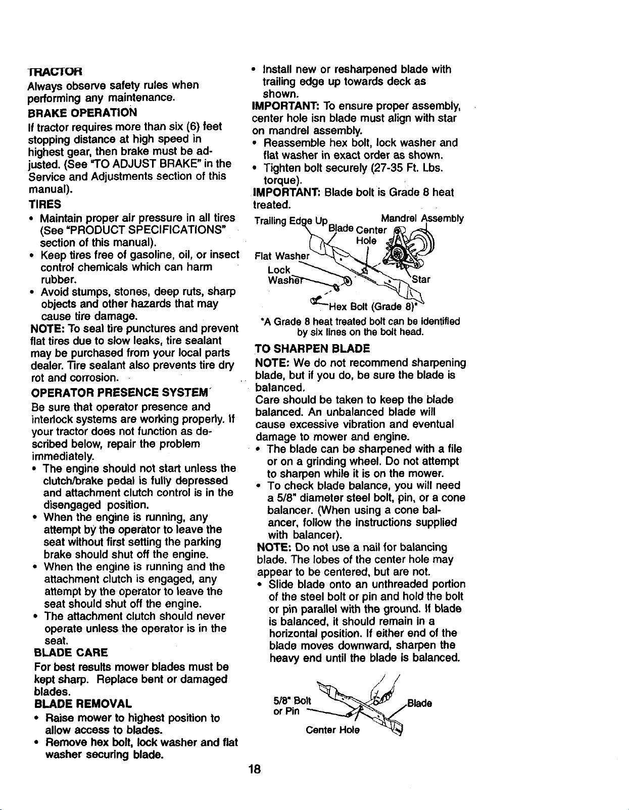
• Install new or resharpened blade with
trailing edge up towards deck as
shown.
IMPORTANT: To ensure proper assembly,
center hole isn blade must align with star
on mandrel assembly.
• Reassemble hex bolt, lock washer and
flat washer in exact order as shown.
• Tighten bolt securely (27-35 Ft. Lbs.
torque).
IMPORTANT: Blade bolt is Grade 8 heat
treated.
,Up Mandrel Assembly
Blade Center
Hole
Lock
_Hex Bolt (Grade
*A Grade 8 heat treated bolt can be identified
by six lines on the bolt head.
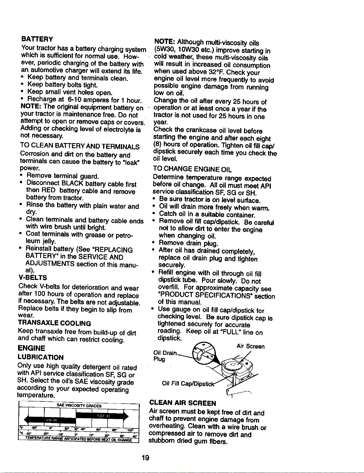
TO SHARPEN BLADE
NOTE: We do not recommend sharpening
blade, but if you do, be sure the blade is
balanced.
Care should be taken to keep the blade
balanced. An unbalanced blade will
cause excessive vibration and eventual
damage to mower and engine.
• The blade can be sharpened with a file
or on a grinding wheel. Do not attempt
to sharpen while it is on the mower.
• To check blade balance, you will need
a 5/8" diameter steel bolt, pin, or a cone
balancer. (When using a cone bal-
ancer, follow the instructions supplied
with balancer).
NOTE: Do not use a nail for balancing
blade. The lobes of the center hole may
appear to be centered, but are not.
• Slide blade onto an unthreaded portion
of the steel bolt or pin and hold the bolt
or pin parallel with the ground. If blade
is balanced, it should remain in a
horizontal position. If either end of the
blade moves downward, sharpen the
heavy end until the blade is balanced.
//
5/8" Bolt __'/,Blade
or Pin
Center Hole _J_._
18
BATTERY
Your tractor has a battery charging system
which is sufficient for normal use. How-
ever, periodic charging of the battery with
an automotive charger will extend its life.
• Keep battery and terminals clean.
: Keep battery bolts tight.
Keep small vent holes open.
NOTE: Although multi-viscosity oils
(5W30, 10W30 etc.) improve starting in
cold weather, these multi-viscosity oils
will result in increased oil consumption
when used above 32°F. Check your
engine oil level more frequently to avoid
possible engine damage from running
low on oil.
• Recharge at 6-10 amperes for 1 hour. Change the oil after every 25 hours of
NOTE: The odginal equ pment battery on "operation or at least once a year if the
your tractor is maintenance free. Do not tractor is not used for 25 hours in one
attempt to open or remove Caps or covers: year.
Adding or checking level of electrolyte is
not necessary.
TO CLEAN BATTERY AND TERMINALS
Corrosion and dirt on the battery and
terminals can cause the battery to "leak"
power.
• Remove terminal guard.
• Disconnect BLACK battery cable first
then RED battery cable and remove
battery from tractor.
• Rinse the battery with plain water and
dry.
• Clean terminals and battery cable ends
with wire brush until bright.
• Coat terminals with grease or petro-
leum jelly.
• Reinstall battery (See "REPLACING
BATTERY" in the SERVICE AND
ADJUSTMENTS section of this manu-
al).
V-BELTS
Check V-belts for deterioration and wear
after 100 hours of operation and replace
if necessary. The belts are not adjustable.
Replace belts if they begin to slipfrom
wear.
TRANSAXLE COOLING
Keep transaxle free from build-up of dirt
and chaff which can restrict cooling.
ENGINE
LUBRICATION
Only use high quality detergent oil rated
with API service classification SF, SG or
SH. Select the oil's SAE viscositygrade
according to your expected operating
temperature.
SAE VISCOSITY GRADES
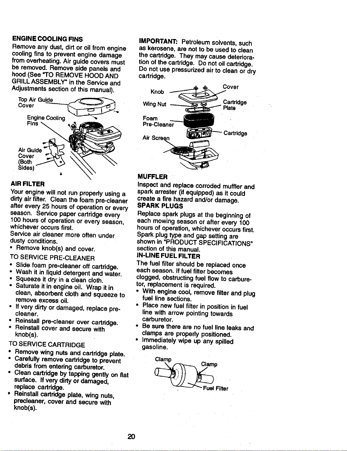
Check the crankcase oil level before
starting the engine and after each eight
(8) hours of operation. Tighten oil fill cap/
dipstick securely each time you check the
oil level.
TO CHANGE ENGINE OIL
Determine temperature range expected
before oil change. All oil must meet API
service classification SF, SG or SH.
• Be sure tractor is on level surface.
• Oil will drain more freely when warm.
• Catch oil in a suitable container.
• Remove oil fill cap/dipstick. Be careful
not to allow dirt to enter the engine
when changing oil
• Remove drain plug.
• After oil has drained completely,
replace oil drain plug and tighten
securely.
• Refill engine with oil through oil fill
dipstick tube. Pour slowly. Do not
overfill. For approximate capacity see
=PRODUCT SPECIFICATIONS" section
of this manual.
• Use gauge on oil fill cap/dipstick for
checking level. Be sure dipstick cap is
tightened securely for accurate
reading. Keep oil at =FULL" line on
dipstick.
Air Screen
Oil Drain-......___ /_-_
Plug .
Oil Fill Cap/Dip_ck -_ __.
CLEAN AIR SCREEN
Air screen must be kept free of dirtand
chaff to prevent engine damage from
overheat_g. Clean with a wire brush or
compressed air to remove dirtand
stubbom dried gum fibers.
19
ENGINE COOLING FINS
Remove any dust, dirt or oil from engine
cooling fins to prevent engine damage
from overheating. Air guide covers must
be removed. Remove side panels and
hood (See =TO REMOVE HOOD AND
GRILLASSEMBLY" in the Service and
Adjustments section of this manual).
Top Air Guide _ _
Cover
,11
Engine Cooling
Fins
Cover
(Both
Sides)
AIR FILTER
Your engine will not run properly using a
dirty air filter. Clean the foam pre-cleaner
after every 25 hours of operation or every
season. Service paper cartridge every
100 hours of operation or every season,
whichever occurs first.
Service air cleaner more often under
dusty conditions.
• Remove knob(s) and cover.
TO SERVICE PRE-CLEANER
• Slide foam pre-cleaner off cartridge.
• Wash it in liquid detergent and water.
• Squeeze it dry in a clean cloth.
• Saturate it in engine oil. Wrap it in
clean, absorbent cloth and squeeze to
remove excess oil.
• If very dirty or damaged, replace pre-
cleaner.
• Reinstall pre-cleaner over cartridge.
• Reinstall cover and secure with
knob(s).
TO SERVICE CARTRIDGE
• Remove wing nuts and cartridge plate.
• Carefully remove cartridge tOprevent
debds from entering carburetor.
• Clean cartridge by tapping gently on flat
surface. If very dirty or damaged,
replace cartridge.
• Reinstall cartridge plate, wing nuts,
precleaner, cover and secure with
knob(s).
IMPORTANT: Petroleum solvents, such
as kerosene, are not to be used to clean
the cartridge. They may cause deteriora-
tion of the cartridge. Do not oil cartridge.
Do not use pressurized air to clean or dry
cartridge.
Cover
Knob
Wing Nut
Cartridge
Foam
Pre-Cleaner
Air Scre n
Cartridge
MUFFLER
Inspect and replace corroded muffler and
spark arrester (if equipped) as it could
create a fire hazard and/or damage.
SPARK PLUGS
Replace spark plugs at the beginning of
each mowing season or after every 100
hours of operation, whichever occurs first.
Spark plug type and gap setting are
shown in "PRODUCT SPECIFICATIONS"
section of this manual.
IN-LINE FUEL FILTER
The fuel filter should be replaced once
each season. If fuel filter becomes
clogged, obstructingfuel flow to carbure-
tor, replacement is required.
• With engine cool, remove filter and plug
fuel line sections.
• Place new fuel filter in position in fuel
line with arrow pointing towards
carburetor.
• Be sure there are no fuel line leaks and
clamps are properly positioned.
• Immediately wipe up any spilled
gasoline.
P
Fuel Filter
2O
CLEANING
• Clean engine, batted/, seat, finish, etc.
of all foreign matter.
• Keep finished surfaces and wheels free
of all gasoline, oil, etc.
• Protect painted surfaces with automo-
tive type wax.
We do not recommend using a garden
hose to clean your tractor unless the
electrical system, muffler, air filter and
carburetor are covered to keep water out.
Water in engine can result in a shortened
engine life.
_CAUTION: Before performing any service or adjustments:
• Depress clutch/brake pedal fully and set parking brake.
• Place gearshift lever in neutral (N) position.
• Place attachment clutch in "DISENGAGED" position.
• Turn ignition key "OFI="and remove key.
• Make sure the blades and all moving parts have completely stopped.
• Disconnect spark plug wire from spark plug and place wire where it cannot come
in contact with plug.
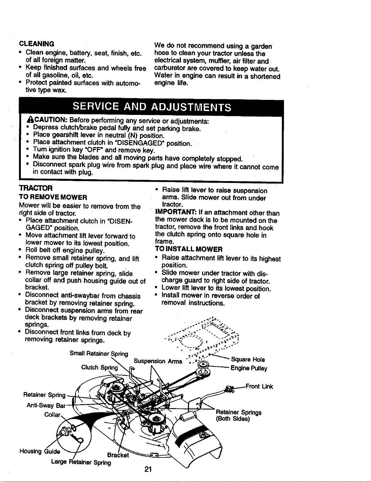
TRACTOR
TO REMOVE MOWER
Mower will be easier to remove from the
right side of tractor.
• Place attachment clutch in"DISEN-
GAGED" position.
• Move attachment lift lever forward to
lower mower to its lowest position.
• Roll belt off engine pulley.
• Remove small retainer spring, and lift
clutch spring off pulley bolt.
• Remove large retainer spring, slide
collar off and push housing guide out of
bracket.
• Disconnect anti-sway!0ar from chassis
bracket by removing retainer spring.
• Disconnect suspension arms from rear
deck brackets by removing retainer
springs.
• Disconnect front links from deck by
removing retainer springs.
Small Retainer Spring
Clutch
• Raise lift lever to raise suspension
arms. Slide mower out from under
tractor.
IMPORTANT: If an attachment other than
the mower deck is to be mounted on the
treJctor, remove the front links and hook
the clutch spring onto square hole in
frame.
TO INSTALL MOWER
• Raise attachment lift lever to its highest
position.
• Slide mower under tractor with dis-
charge guard to fight side of tractor.
• Lower lift lever to its lowest position.
• Install mower in reverse order of
removal instructions.
Suspension Arms ""Jl
Retainer
Anti-Sway
Springs
(BothSides)
HousingGuide
La_q
21
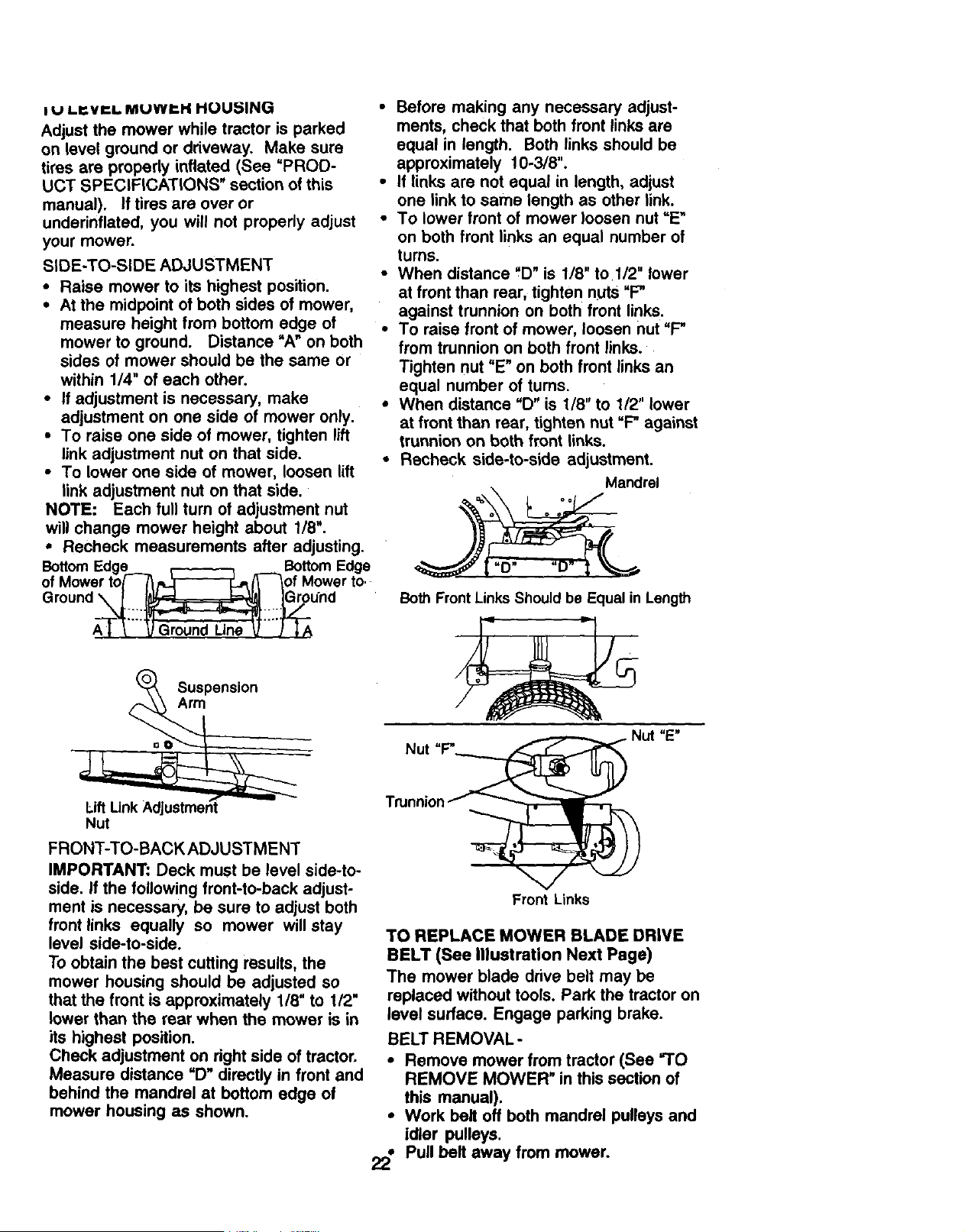
! U Lr.VI=I.. MUWP-.H HUU_ING
Adjust the mower while tractor is parked
on level ground or ddveway. Make sure
tires are properly inflated (See =PROD-
UCT SPECIFICATIONS" section of this
manual). If tires are over or
undednflated, you will not properly adjust
your mower.
SIDE-TO-SiDE ADJUSTMENT
• Raise mower to its highest position.
• At the midpoint of both sides of mower,
measure height from bottom edge of
mower to ground. Distance =A" on both
sides of mower should be the same or
within 1/4" of each other.
• If adjustment is necessary, make
adjustment on one side of mower only.
• To raise one side of mower, tighten lift
link adjustment nut on that side.
• To lower one side of mower, loosen lift
link adjustment nut on that side.
NOTE: Each full turn of adjustment nut
will change mower height about 1/8".
• Recheck measurements after adjusting.
Bottom Edge__._ _ _ Bottom Edge
of Mower to/ /_,_/_ _of Mower to.
Ground X,_._.I_ __.ou'n d
Qroun Une
• Before making any necessary adjust-
ments, check that both front links are
equal in length. Both links should be
approximately 10-3/8".
• If links are not equal in length, adjust
one link to same length as other link.
• To lower front of mower loosen nut =E"
on both front links an equal number of
turns.
• When distance ,D" is 1/8" to 1/2" lower
at front than rear, tighten nuts "F"
against trunnion on both front links.
• To raise front of mower, loosen nut "F"
from trunnion on both front links.
Tighten nut "E" on both front links an
equal number of tums.
• When distance =D" is 1/8" to 1/2" lower
at front than rear, tighten nut "F" against
trunnion on both front links.
• Recheck side-to-side adjustment.
Mandrel
qD oo
Both Front Links Should be Equal in Length
Suspension
Arm
Lift
Nut
FRONT-TO-BACK ADJUSTMENT
IMPORTANT: Deck must be level side-to-
side. If the following front-to-back adjust-
ment is necessary, be sure to adjust both
front links equally so mower will stay
level side-to-side.
To obtain the best cutting results, the
mower housing should be adjusted so
that the front is approximately 1/8" to 1/2"
lower than the rear when the mower is in
its highest position.
Check adjustment on dght side of tractor.
Measure distance =D" directly in front and
behind the mandrel at bottom edge of
mower housing as shown.
Front Links
TO REPLACE MOWER BLADE DRIVE
BELT (See Illustration Next Page)
The mower blade drive belt may be
replaced without tools, Park the tractor on
level surface. Engage parking brake.
BELT REMOVAL -
• Remove mower from tractor (See "TO
REMOVE MOWER" in this section of
this manual).
• Work belt off both mandrel pulleys and
idler pulleys.
• Pull belt away from mower.
22
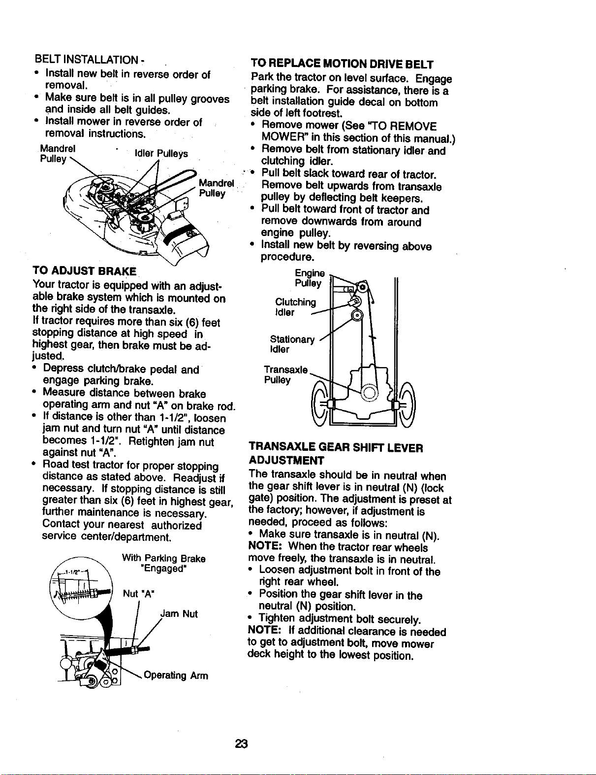
BELT INSTALLATION -
• Install new belt in reverse order of
removal.
• Make sure belt is in all pulley grooves
and inside all belt guides,
• Install mower in reverse order of
removal instructions.
Mandrel Idler Pulleys
TO REPLACE MOTION DRIVE BELT
Park the tractor on level surface. Engage
• parking brake. For assistance, there is a
belt installation guide decal on bottom
side of left footrest.
• Remove mower (See =1"0 REMOVE
MOWER" in this section of this manual.)
• Remove belt from stationary idler and
clutching idler.
' • Pull belt slack toward rear of tractor.
Mandrel Remove belt upwards from transaxle
Pulley pulley by deflecting belt keepers.
• Pull belt toward front of tractor and
remove downwards from around
engine pulley.
• Install new belt by reversing above
procedure.
TO ADJUST BRAKE
Your tractor is equipped with an adjust-
able brake system which is mounted on
the right side of the transaxle.
If tractor requires more than six (6) feet
stopping distance at high speed in
highest gear, then brake must be ad-
justed.
• Depress clutch/brake pedal and
engage parking brake.
• Measure distance between brake
operating arm and nut "A" on brake rod.
• If distance is other than 1-1/2", loosen
jam nut and turn nut "A" until distance
becomes 1-1/2". Retighten jam nut
against nut "A".
• Road test tractor for proper stopping
distance as stated above. Readjust if
necessary. If stopping distance is still
greater than six (6) feet in highest gear,
further maintenance is necessary.
Contact your nearest authorized
service center/department.
With Parking Brake
"Engaged"
Nut "A"
Engine
Pulley
Clutching
Idler I"
Stationary /
Idler
TRANSAXLE GEAR SHIFT LEVER
ADJUSTMENT
The trensaxle should be in neutral when
the gear shift lever is in neutral (N) (lock
gate) position. The adjustment is preset at
the factory; however, if adjustment is
needed, proceed as follows:
• Make sure transaxle is in neutral (N).
NOTE: When the tractor rear wheels
move freely, the transaxle is in neutral.
• Loosen adjustment bolt in front of the
right rear wheel.
• Position the gear shift lever in the
neutral (N) position.
• Tighten adjustment bolt securely.
NOTE: If additional clearance is needed
to get to adjustment bolt, move mower
deck height to the lowest position.
23
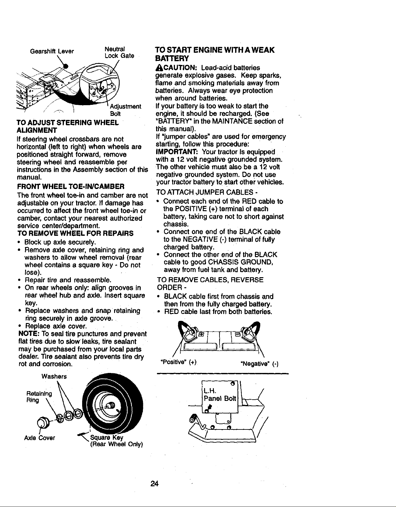
Gearshift Lever Neutral
Lock Gate
...... Adjustment
Bolt
TO ADJUST STEERING WHEEL
ALIGNMENT
If steedng wheel crossbars are not
hodzontal (left to right) when wheels are
positioned straight forward, remove
steering wheel and reassemble per
instructionsin the Assembly section of this
manual.
FRONT WHEEL TOE-IN/CAMBER
The front wheel toe-in and camber are not
adjustable on your tractor, if damage has
occurred to affect the front wheel toe-in or
camber, contact your nearest authorized
service center/department.
TO REMOVE WHEEL FOR REPAIRS
• Block up axle securely.
• Remove axle cover, retaining ring and
washers to allow wheel removal (rear
wheel contains a square key - Do not
lose).
• Repair tire and reassemble.
• On rear wheels only: align grooves in
rear wheel hub and axle. Insert square
key.
• Replace washers and snap retaining
ring securely in axle groove.
• Replace axle cover.
NOTE: To seal tire punctures and prevent
flat tires due to slow leaks, tire sealant
may be purchased from your local parts
dealer. Tire sealant also prevents tire dry
rot and corrosion.
Washers
Retaining
Ring \
Axle Cover
Key
(Rear Wheel Only)
TO START ENGINE WITH A WEAK
BATTERY
_IbCAUTION: Lead-acid batteries
generate explosive gases. Keep sparks,
flame and smoking materials away from
batteries. Always wear eye protection
when around batteries.
If your battery is too weak to start the
engine, it should be recharged. (See
"BATTERY" in the MAINTANCE section of
this manual).
If =jumper cables" are used for emergency
starting, follow this procedure:
IMPORTANT: Your tractor Is equipped
with a t 2 volt negative grounded system.
The other vehicle must also be a 12 volt
negative grounded system. Do not use
your tractor battery to start other" vehicles.
TO ATTACH JUMPER CABLES -
• Connect each end of the RED cable to
the POSITIVE (+) terminal of each
battery, taking care not to short against
chassis.
• Connect one end of the BLACK cable
to the NEGATIVE (-) terminal of fully
charged battery.
• Connect the other end of the BLACK
cable to good CHASSIS GROUND,
away from fuel tank and battery.
TO REMOVE CABLES, REVERSE
ORDER -
• BLACK cable first from chassis and
then from the fully charged battery.
• RED cable last from both batteries.
=Positive" (+) =Negative" (-)
24
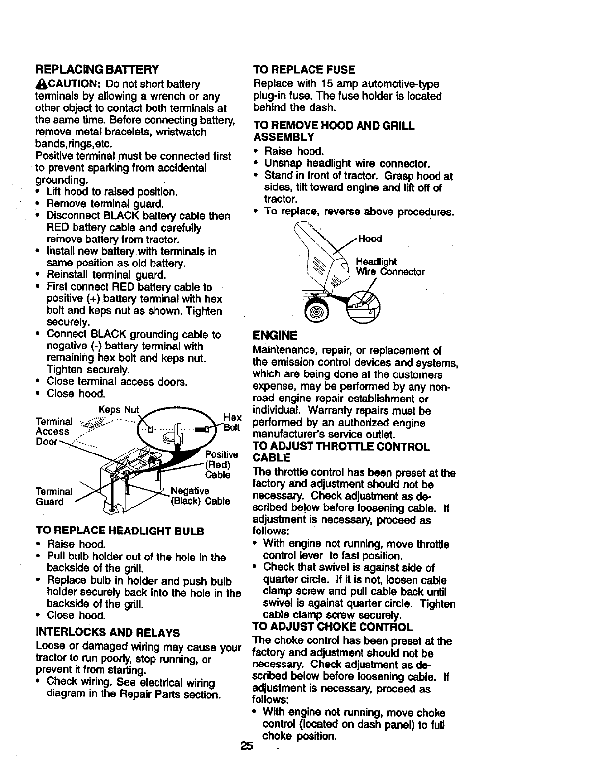
REPLACING BATTERY
_CAUTION: Do not shortbattery
terminals by allowing a wrench or any
other object to contact both terminals at
the same time. Before connecting battery,
remove metal bracelets, wristwatch
bends,rings,etc.
Positiveterminal must be connected first
to prevent sparking from accidental
grounding.
• Lift hood to raised position.
• Remove terminal guard.
• Disconnect BLACK battery cable then
RED battery cable and carefully
remove battery from tractor.
• Install new battery with terminals in
same position as old battery.
• Reinstall terminal guard.
• First connect RED battery cable to
positive (+) battery terminal with hex
bolt and keps nut as shown. Tighten
securely.
• Connect BLACK grounding cable to
negative (-) battery terminal with
remaining hex bolt and keps nut.
Tighten securely.
• Close terminal access doors.
• Close hood.
Terminal -_!_" ...........
Access ..-;'""
Positive
Terminal Negative
Guard Black) Cable
TO REPLACE HEADLIGHT BULB
• Raise hood.
• Pull bulb holder out of the hole in the
backside of the grill.
• Replace bulb in holder and push bulb
holder securely back into the hole in the
backside of the grill.
• Close hood.
INTERLOCKS AND RELAYS
Loose or damaged wiring may cause your
tractor to run poody, stop running, or
prevent it from starting.
• Check widng. See electdcal wiring
diagram in the Repair Parts section.
TO REPLACE FUSE
Replace with 15 amp automotive-type
plug-in fuse. The fuse holder is located
behind the dash.
TO REMOVE HOOD AND GRILL
ASSEMBLY
• Raise hood.
• Unsnap headlight wire connector.
• Stand in front of tractor. Grasp hood at
sides, tilttoward engine and liftoff of
tractor.
• To replace, reverse above procedures.
Hood
! _%_\/_ Headlightnector
ENGINE
Maintenance, repair, or replacement of
the emission control devices and systems,
which are being done at the customers
expense, may be performed by any non-
road engine repair establishment or
individual. Warranty repairs must be
performed by an authorized engine
manufacturer's service outlet.
TO ADJUST THROTTLE CONTROL
CABLE
The throttle control has been preset at the
factory and adjustment should not be
necessary. Check adjustment as de-
scribed below before loosening cable. If
adjustment is necessary, proceed as
follows:
• With engine not running, move throttle
control lever to fast position.
• Check that swivel is against side of
quarter cimle. If it is not, loosen cable
clamp screw and pull cable back until
swivel is against quarter cimle. Tighten
cable clamp screw securely.
TO ADJUST CHOKE CONTROL
The choke control has been preset at the
factory and adjustment should not be
necessary. Check adjustment as de-
scribed below before loosening cable. If
adjustment is necessary, proceed as
follows:
• With engine not running, move choke
control (located on dash panel) to full
choke position.
25
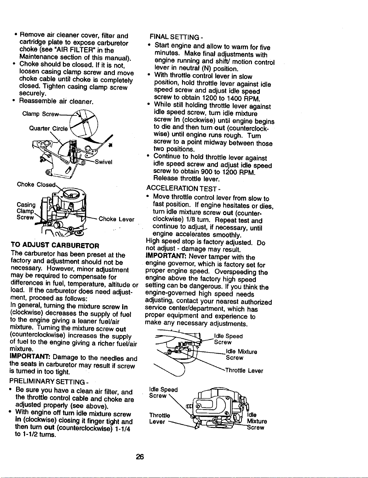
• Remove air cleaner cover, filter and
cartridge plate to expose carburetor
choke (see "AIR FILTER" in the
Maintenance section of this manual).
• Choke should be closed. If it is not,
loosen casing clamp screw and move
choke cable until choke is completely
closed. Tighten casing clamp screw
securely.
• Reassemble air cleaner.
Clamp Scre_
Quarter Circle _ "_a
2g:
Choke CI_=
Casing | I_--_
Clamp.. | _'1_
Screw _
"---'-Choke Lever
TO ADJUST CARBURETOR
The carburetor has been preset at the
factory and adjustment should not be
necessary. However, minor adjustment
may be required to compensate for
differences in fuel, temperature, altitude or
load. If the carburetor does need adjust-
ment, proceed as follows:
In general, turning the mixture screw in
(clockwise) decreases the supply of fuel
to the engine giving a leaner fuel/air
mixture. Turning the mixture screw out
(counterclockwise) increases the supply
of fuel to the engine giving a richer fuel/air
mixture.
IMPORTANT: Damage to the needles and
the seats in carburetor may result if screw
is tumed in too tight.
PRELIMINARY SEI-I'ING -
• Be sure you have a clean air filter, and
the throttle control cable and choke are
adjusted properly (see above).
• With engine off turn idle mixture screw
in (clockwise) closing it finger tight and
then turn out (counterclockwise) 1-1/4
to 1-1/2 turns.
FINAL SETTING -
• Start engine and allow to warm for five
minutes. Make final adjustments with
engine running and shift/motion control
lever in neutral (N) position.
• With throttle control lever in slow
position, hold throttle lever against idle
speed screw and adjust idle speed
screw to obtain 1200 to 1400 RPM.
• While still holding throttle lever against
idle speed screw, turn idle mixture
screw In (clockwise) until engine begins
to die and then turn out (counterclock-
wise) until engine runs rough. Tum
screw to a point midway between those
two positions.
• Continue to hold throttle lever against
idle speed screw and adjust idle speed
screw to obtain 900 to 1200 RPM.
Release throttle lever.
ACCELERATION TEST-
• Move throttle control lever from slow to
fast position. If engine hesitates or dies,
turn idle mixture screw out (counter-
clockwise) 118 turn. Repeat test and
continue to adjust, if necessary, until
engine accelerates smoothly.
High speed stop is factory adjusted. Do
not adjust - damage may result.
IMPORTANT: Never tamper with the
engine governor, which is factory set for
proper engine speed. Overspeeding the
engine above the factory high speed
setting can be dangerous. If you think the
engine-governed high speed needs
adjusting, contact your nearest authorized
service center/department, which has
proper equipment and experience to
make any necessary adjustments.
ldle Speed
crew
Idle Mixture
Screw
Throttle Lever
Idle Speed ,.r-_=_====_
Screw __
. _ _ _))_J Idle
Throttle _ .._,_ I_.n ;, . .
L ver - ( ",,.,_--_=(t_:::z"_,.._u MIXTUre
e - crew
26
Immediately prepare your tractor for
storage at the end of the season or ifthe
tractor will not be used for 30 days or
more.
Also, experience indicates that alcohol
blended fuels (called gasohol or using
ethanol or methanol) can attract moisture
which leads to separation and formation o
_CAUTION: Never store the tractor with acids during storage. Acidic gas can
gasoline in the tank inside a building damage the fuel system of an engine
where fumes may reach an open flame or while in storage.
spark. Allow the engine to cool before • Drain the fuel tank.
storing in any enclosure.
TRACTOR
Remove mower from tractor for winter
storage. This will allow you to clean it
thoroughly. Remove all dirt, grease,
leaves, etc. Store in a clean, dry area.
• Clean entire tractor (See =CLEANING"
in the Maintenance section of this
manual).
• Inspect and replace belts, if necessary
(See belt replacement instructions in
the Service and Adjustments section of
this manual).
• Lubricate as shown in the Maintenance
section of this manual.
• Be sure that all nuts, bolts and screws
are securely fastened. Inspect moving
parts for damage, breakage and wear.
Replace if necessary.
• Touch up all rusted or chipped paint
surfaces; sand lightly before painting.
BATTERY
• Fully charge the battery for storage.
• After a period of time in storage, battery
may require recharging.
• To help prevent corrosion and power
leakage during long periods of storage,
battery cables should be disconnected
and battery cleaned thoroughly (see
"TO CLEAN BATTERY AND TERMI-
NALS" in the Maintenance section of
this manual).
• After cleaning, leave cables disconnect-
ed and place cables where they cannot
come in contact with battery terminals.
• If battery is removed from tractor for
storage, do not store battery directly on
concrete or damp surfaces.
ENGINE
FUEL SYSTEM
IMPORTANT: It is important to prevent
gum deposits from forming in essential
fuel system parts such as carburetor, fuel
filter, fuel hose, or tank during storage.
• Start the engine and let it run until the
fuel lines and carburetor are empty.
• Never use engine or carburetor cleaner
products in the fuel tank or permanent
damage may occur.
• Use fresh fuel next season.
NOTE: Fuel stabilizer is an acceptable
alternative in minimizing the formation of
fuel gum deposits during storage. Add
stabilizer to gasoline in fuel tank or
storage container. Always follow the mix
ratio found on stabilizer container. Run
engine at least 10 minutes after adding
stabilizer to allow the stabilizer to reach
the carburetor. Do not drain the gas tank
and carburetor if using fuel stabilizer.
ENGINE OIL
Drain oil (with engine warm) and replace
with clean engine oil. (See =ENGINE" in
the Maintenance section of this manual).
CYLINDER(S)
• Remove spark plug(s).
• Pour one ounce of oil through spark
plug hole(s) into cylinder(s).
• Turn ignition key to "START" position for
a few seconds to distribute oil.
• Replace with new spark plug(s).
OTHER
• Do not store gasoline from one season
to another.
• Replace your gasoline can if it starts to
rust. Rust and/or dirt in your gasoline
will cause problems.
• If possible, store your tractor indoors
and cover it to give protection from dust
and dirt.
• Cover your tractor with a suitable
protective cover that does not retain
moisture. Do not use plastic. Plastic
cannot breathe, which allows conden-
sation to form and cause your tractor to
rust.
IMPORTANT: Never cover tractor while
engine and exhaust areas are still warm.
27
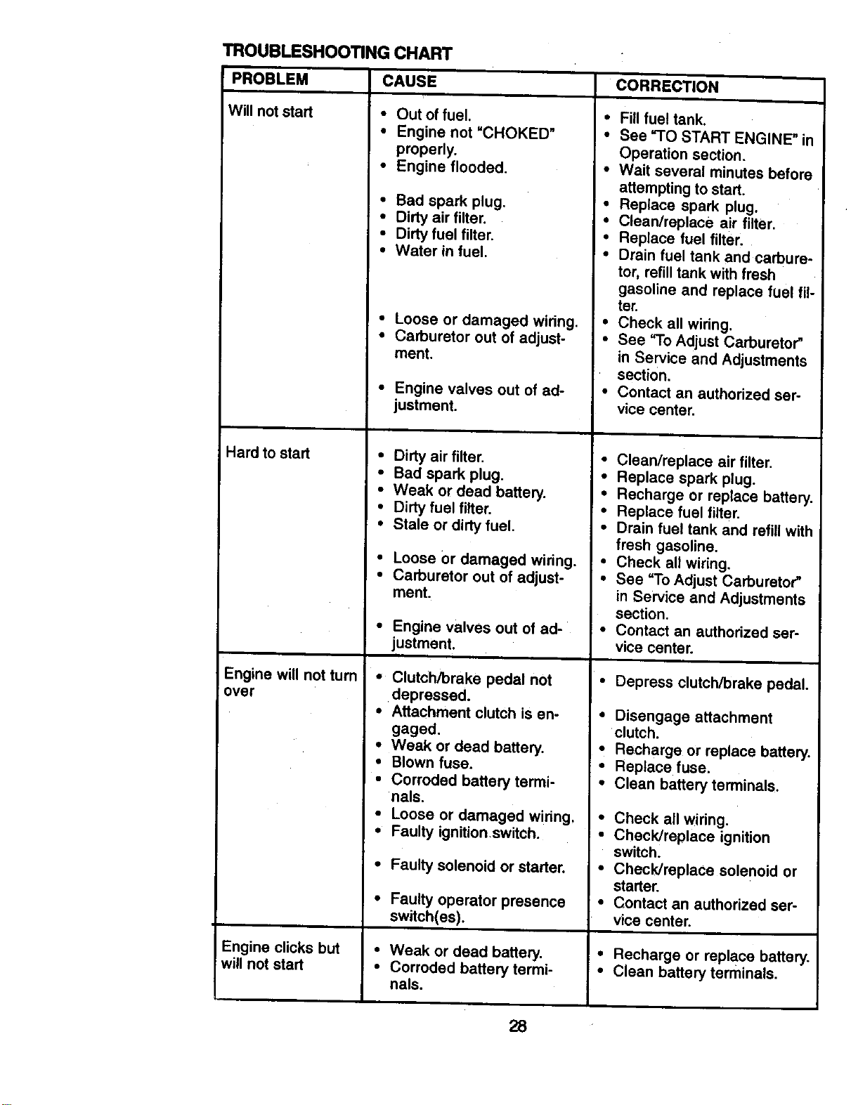
TROUBLESHOOTING CHART
PROBLEM CAUSE
Will notstart
Hard to start
Engine will not turn
over
• Out of fuel.
• Engine not =CHOKED"
properly.
• Engine flooded.
• Bad spark plug.
• Dirty air filter.
• Dirty fuel filter.
• Water in fuel.
• Loose or damaged wiring.
• Carburetor out of adjust-
ment.
Engine clicks but
will not start
• Engine valves out of ad-
justment.
• Dirty air filter.
• Bad spark plug.
• Weak or dead battery.
• Dirty fuel filter.
• Stale or dirty fuel.
• Loose Ordamaged wiring.
• Carburetor out of adjust-
ment.
• Engine valves out of ad-
justment.
• Clutch/brake pedal not
depressed.
• Attachment clutch is en-
gaged.
• Weak or dead battery.
• Blown fuse.
• Corroded battery termi-
nals.
• Loose or damaged wiring,
• Faulty ignition,switch.
• Faulty solenoid or starter.
• Faulty operator presence
switch(es).
• Weak or dead battery,
• Corroded battery termi-
nals.
CORRECTION
• Fill fuel tank.
• See "TO START ENGINE" in
Operation section.
• Wait several minutes before
attempting to start.
• Replace spark plug.
• Clean/replace air filter.
• Replace fuel filter.
• Drain fuel tank and carbure-
tor, refill tank with fresh
gasoline and replace fuel fil-
ter.
• Check all wiring,
• See "To Adjust Carburetor"
in Service and Adjustments
section.
• Contact an authorized ser-
vice center.
• Clean/replace air filter.
• Replace spark plug.
• Recharge or replace battery.
• Replace fuel filter.
• Drain fuel tank and refill with
fresh gasoline.
• Check all wiring.
• See "To Adjust Carburetor"
in Service and Adjustments
section.
• Contact an authorized ser-
vice center.
• Depress clutch/brake pedal.
• Disengage attachment
clutch.
• Recharge or replace battery.
• Replace fuse.
• Clean battery terminals.
• Check all wiring.
• Check/replace ignition
switch.
• Check/replace solenoid or
starter.
• Contact an authorized ser-
vice center.
• Recharge or replace battery.
• Clean battery terminals.
28
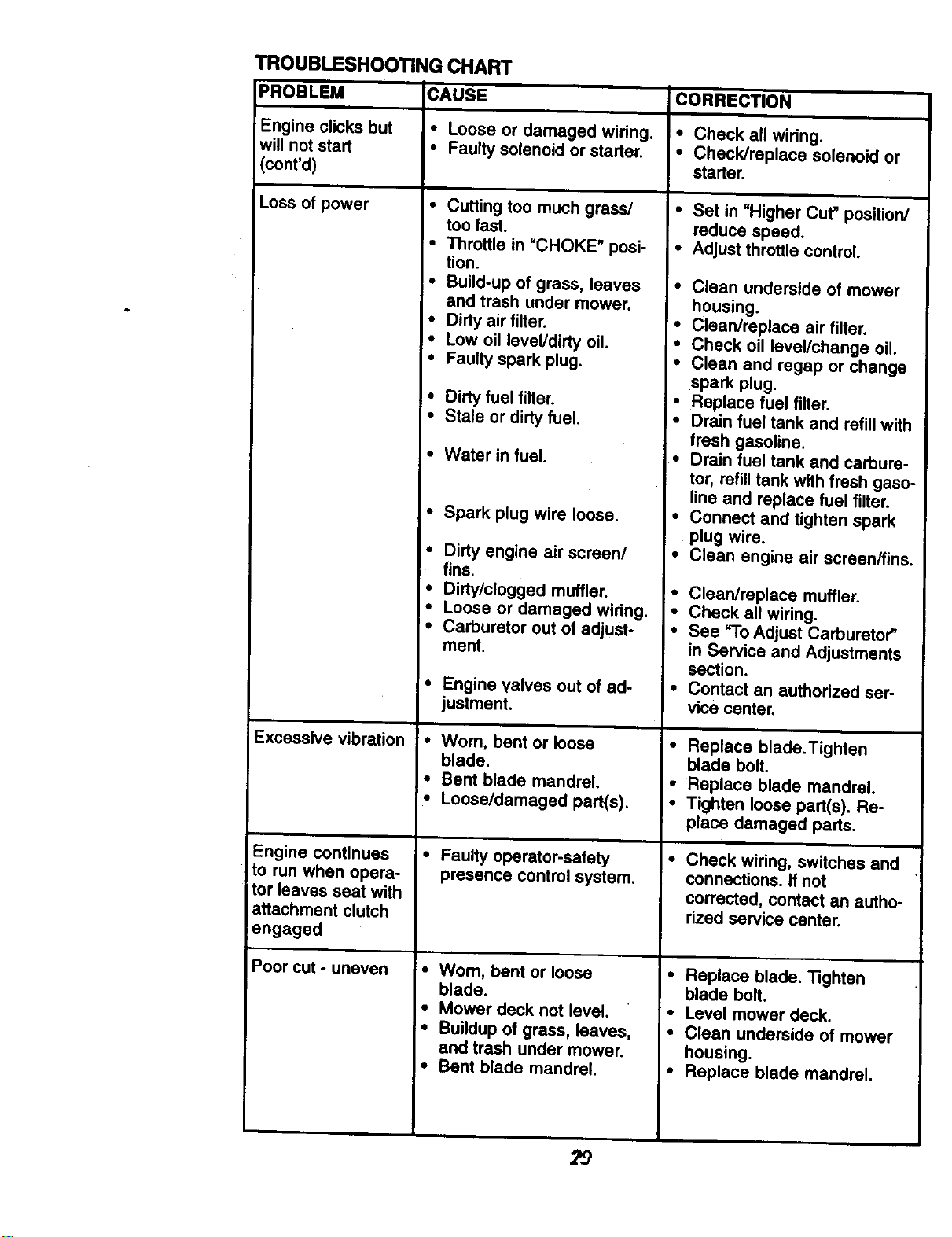
TROUBLESHOOTINGCHART
PROBLEM CAUSE CORRECTION
Engine clicks but * Loose or damaged wiring. * Check all wiring.
will not start * Faulty solenoid or starter. • Check/replace solenoid or
!(cont'd) starter.
Loss of power • Cutting too much grass/
too fast.
• Throttle in =CHOKE" posi-
tion.
* Build-up of grass, leaves
and trash under mower.
* Dirty air filter.
* Low oil level/dirty oil.
• Faulty spark plug.
• Dirty fuel filter.
• Stale or dirtyfuel.
Excessive vibration
Engine continues
to run when opera-
tor leaves seat with
attachment clutch
engaged
Poor cut - uneven
• Water in fuel.
• Spark plug wire loose.
• Dirty engine air screen/
fins.
• Dirty/clogged muffler.
• Loose or damaged wiring.
• Carburetor out of adjust-
ment.
• Engine valves out of ad-
justment.
• Worn, bent or loose
blade.
• Bent blade mandrel.
• Loose/damaged part(s).
• Faulty operator-safety
presence control system,
=• Worn, bent or loose
blade,
• Mower deck not level.
• Buildup of grass, leaves,
and trash under mower,
• Bent blade mandrel.
• Set in =Higher Cut" position/
reduce speed.
• Adjust throttle control.
• Clean underside of mower
housing.
• Clean/replace air filter.
• Check oil level/change oil.
• Clean and regap or change
spark plug.
• Replace fuel filter.
• Drain fuel tank and refill with
fresh gasoline.
• Drain fuel tank and carbure-
tor, refill tank with fresh gaso-
line and replace fuel filter.
• Connect and tighten spark
plug wire.
• Clean engine air screen/fins.
° Clean/replace muffler.
• Check all wiring.
• See 9"0 Adjust Carburetor"
in Service and Adjustments
section.
• Contact an authorized ser-
vice center.
• Replace blade.Tighten
blade bolt.
• Replace blade mandrel.
• Tighten loose part(s). Re-
place damaged parts.
• Check wiring, switches and
connections. If not
corrected, contact an autho-
rized service center.
• Replace blade. Tighten
blade bolt.
• Level mower deck.
• Clean underside of mower
housing.
• Replace blade mandrel.
29
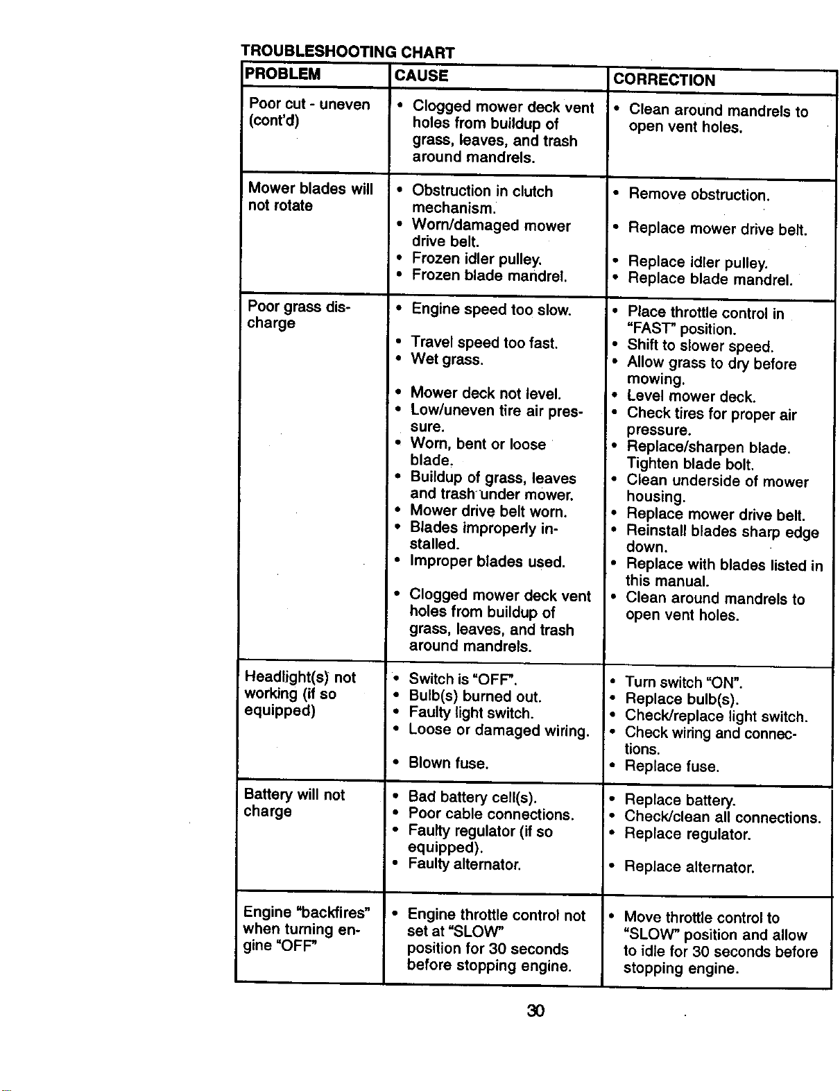
TROUBLESHOOTING CHART
PROBLEM CAUSE CORRECTION
Poor cut- uneven • Clogged mower deck vent • Clean around mandrels to
(cont'd) holes from buildup of open vent holes.
grass, leaves, and trash
around mandrels.
Mower blades will • Remove obstruction.
not rotate
Poor grass dis-
charge
Headlight(s) not
working (if so
equipped)
Battery will not
charge
Engine "backfires"
when turning en-
gine "OFP
• Obstruction in clutch
mechanism_
• Worn/damaged mower
drive belt.
• Frozen idler pulley.
• Frozen blade mandrel.
• Engine speed too slow.
• Travel speed too fast,
• Wet grass.
• Mower deck not level.
• Low/uneven tire air pres-
sure.
• Worn, bent or loose
blade.
• Buildup of grass, leaves
and trashunder mower.
• Mower drive belt worn.
• Blades impropedy in-
stalled.
• Improper blades used.
Clogged mower deck vent
holes from buildup of
grass, leaves, and trash
around mandrels.
• Switch is "OFP.
• Bulb(s) burned out.
• Faulty light switch.
• Loose or damaged wiring.
• Blown fuse.
• Bad battery cell(s).
• Poor cable connections.
• Faulty regulator (if so
equipped).
• Faulty alternator.
• Engine throttle control not
set at "SLOW"
position for 30 seconds
before stopping engine.
• Replace mower drive belt.
• Replace idler pulley.
• Replace blade mandrel.
• Place throttle control in
"FAST" position.
• Shift to slower speed.
• Allow grass to dry before
mowing.
• Level mower deck.
• Check tires for proper air
pressure.
• Replace/sharpen blade.
Tighten blade bolt.
• Clean underside of mower
housing.
• Replace mower drive belt.
• Reinstall blades sharp edge
down.
• Replace with blades listed in
this manual.
• Clean around mandrels to
open vent holes.
• Turn switch "ON".
• Replace bulb(s).
• Check/replace light switch.
• Check wiring and connec-
tions.
• Replace fuse.
I" Replace battery.
i" Check/clean all connections.
• Replace regulator.
• Replace alternator.
• Move throttle control to
"SLOW" position and allow
to idle for 30 seconds before
stopping engine.
3O
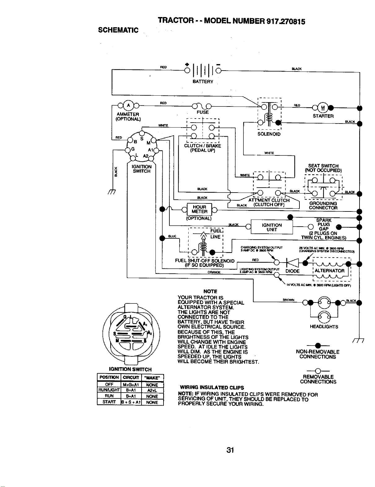
SCHEMATIC
TRACTOR - - MODEL NUMBER 917.270815
BATTERY
AMMETER
(OPTIONAL)
IGNITION
SWITCH
RED
I_ ....... 1
CLUTCH / BRAKE
(PEDAL UP)
i ......
SOLENOID
WHITE
STARTER
IBLACK
SEATSWITCH
(NOT OCCUPIED)
I
GROUNDING
CONNECTOR
etACK (CLUTCH OFF)
(OPTIONAL)
', FuE_
I
i
',m SPARK
IGNITION _ PLUG
UNIT GAP
PLUGS ON
TWIN CYL ENGINES)
FUEL SHUT-OFF SOLENOID
IGNmON SWITCH
NOTE
YOUR TRACTOR IS
EQUIPPED WITH A SPECIAL
ALTERNATOR SYSTEM.
THE LIGHTS ARE NOT
CONNECTED TO THE
BATTERY, BUT HAVE THEIR
OWN ELECTRICAL SOURCE.
BECAUSE OF THIS, THE
BRIGHTNESS OF THE LIGHTS
WILL CHANGE WITH ENGINE
SPEED. AT IDLE THE LIGHTS
WILL DIM. AS THE ENGINE IS
SPEEDED UP, THE LIGHTS
WILL BECOME THEIR BRIGHTEST.
BROWN
HEADLIGHTS
F,
e
NON-REMOVABLE
CONNECTIONS
©
REMOVABLE
CONNECTIONS
WIRING INSULATED CUPS
NOTE: IF WIRING INSULATED CLIPS WERE REMOVED FOR
SERVICING OF UNIT. THEY SHOULD BE REPLACED TO
PROPERLY SECURE YOUR WIRING.
31
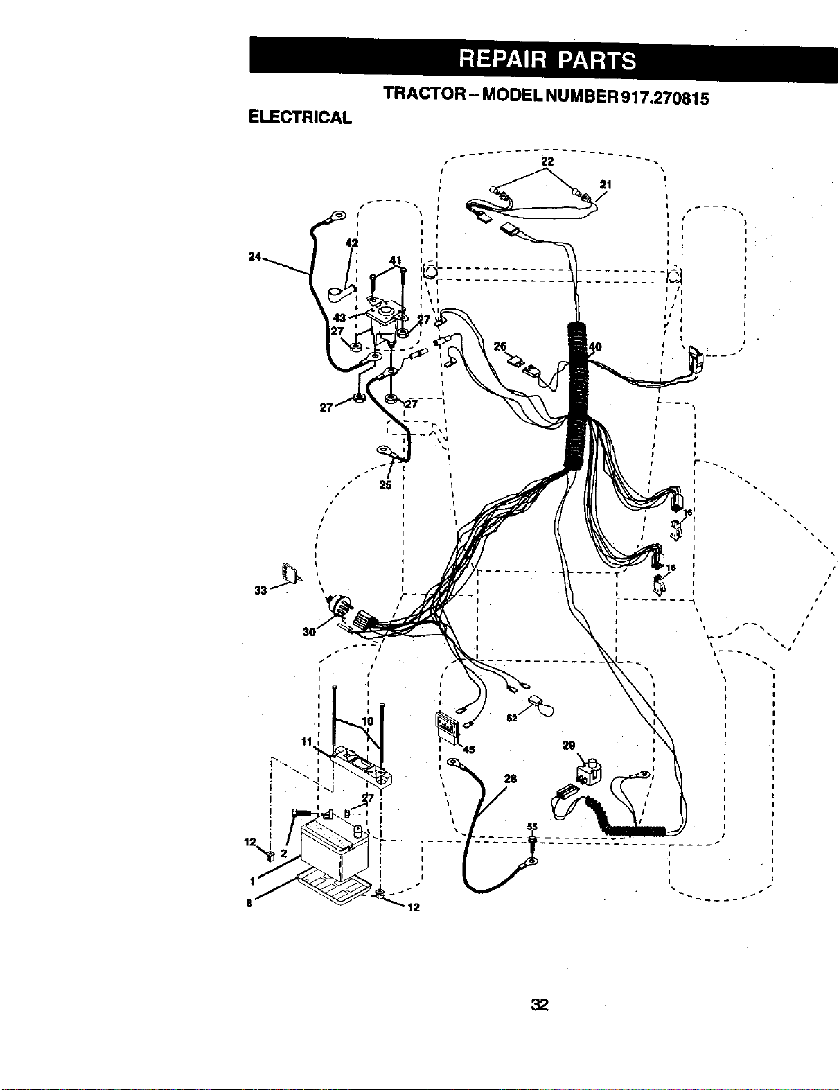
ELECTRICAL
TRACTOR - MODELNUMBER 917.270815
25
i #
I
#
!
I
I
I
#
/
#
#
#
##
32
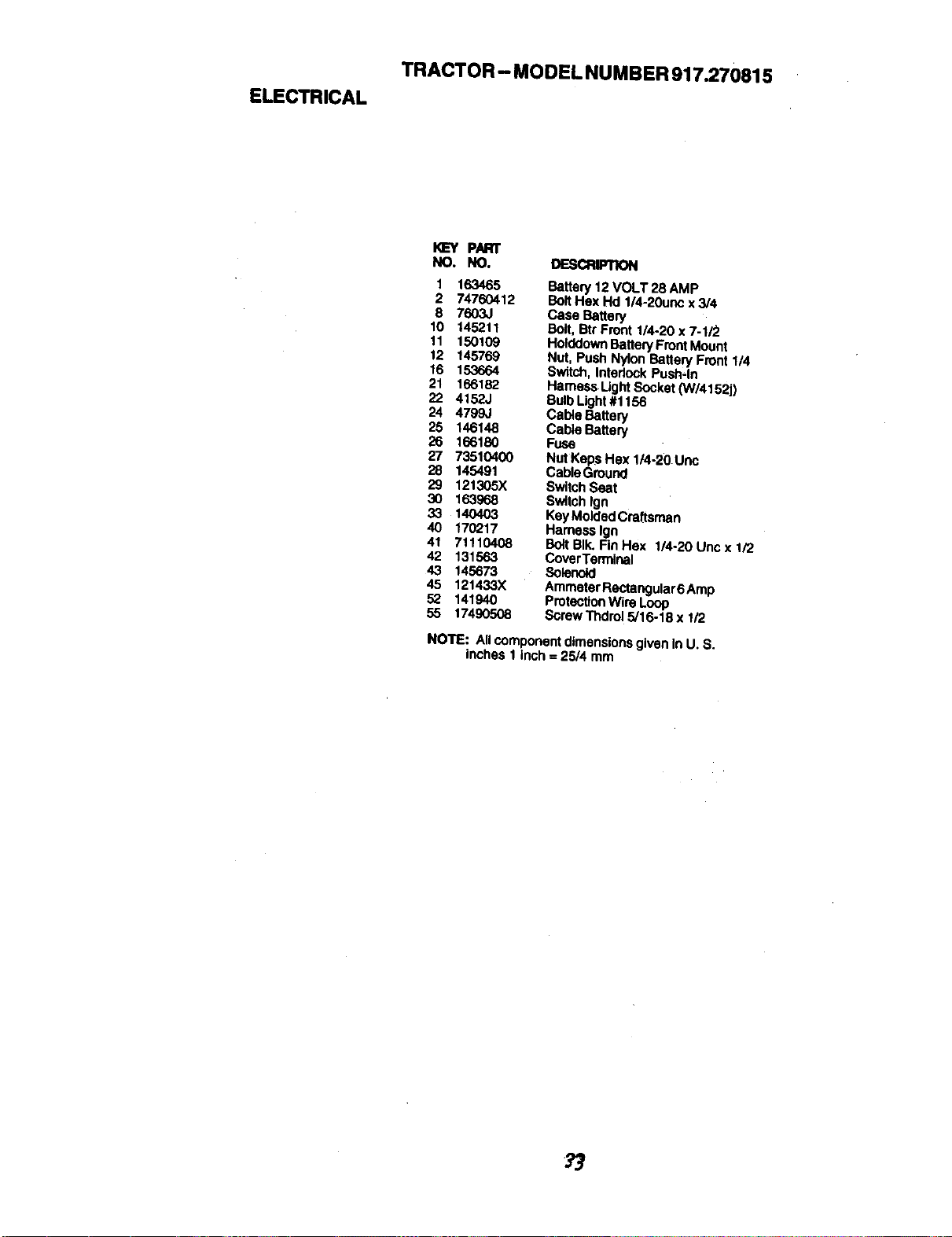
ELECTRICAL
TRACTOR- MODEL NUMBER917.270015
I_'Y P._l"
NO. NO. DE_FI_
1 163465 Battery 12 VOLT 28 AMP
2 74760412 BoltHex Hd 1/4-20ur_: x3/4
8 7603J Case Battery
10 145211 Bolt, BtrFront 1/4-20 x 7-1/2
11 150109 HokldovmBattery Front Motmt
12 145769 Nut, Push Nylon Battery Front1/4
16 153664 Switch, Interlock Push-In
21 166182 Hameas Ught Socket (W/4152j)
22 4152J BulbLight#1156
24 4799J Cable Battery
25 146148 Cable Battery
26 166180 Fuse
27 73510400 Nut Keps Hex 1/4-20 Unc
28 145491 Cable Ground
29 121305X SwitchSeat
30 163968 Switch tgn
33 140403 KeyMolded Craftsman
40 170217 Hameas |gn
41 71110408 BoltBIk. Fin Hex 1/4-20 Unc x 1/2
42 131563 CoverTen'_nal
43 145673 Solerlok:l
45 121433X Ammeter Rectangutar6 Amp
52 141940 ProtectionWire Loop
55 17490508 Screw Thdrol 5/16-18 x 1/2
NOTE: Allcomponent dimensionsgiven In U. S.
inches 1 inch = 25/4 mm

TRACTOR - MODEL NUMB ER 917.270815
CHASSIS AND ENCLOSURES
28
58 12
207
53
2O
23
S4
207
3
74
)l,o,j [
2O8
34

TRACTOR - MODEL NUMBER 917.270815
CHASSIS AND ENCLOSURES
I<_Y PART
NO. NO. DESCRIPTION
1 16983O
2 169061
8 17060612
5 '155272
9 168337X613
10 SrD533710
11 155927
12 145660
13 1721(_
17 144983x558
18 126938X
20 156437
23 124028)(
25 19131312
26 STD541437
28 156725)(558
29 155217X599
30 164916X558
31 139976
37 1749O5O8
38 169834
51 73800400
52 19091416
53 145201
54 161464
55 145202
57 STD522507
58 140547
60 STD533707
64 154798
74 S'TD541437
114 158112
115 17060620
142 165867
143 154966
144 154207
145 156524
206 170165
207 17670508
208 17670608
211 145212
Chass'_sAssembly
Dmwbar
Screw 3/8o16x 3/4
BumperHood/Dash
Dash
Bolt, Carriage 3/8-16 x 1
Panel, Dash, L.H.
ClipTinnerman GdlleP/L
Panel, Dash, R.H.
HoodAssembly
BumperHood
Plate Mtg Battery FuelTank
Bushing,Snap, Nylon,Fuel Line
Washer 13/32 x 13/16 x 12 Gauge
Locknut, Hex, with Insert3/8-16 uric
Gdlle,'LensAsm
Lens, Grille
FendiFtrest
Bracket,Fender Support
ScrewThdrol 5/16o18 x 1/2
Pivot Bracket Assembly, L.H,
Nut Lock w/Insert 1/4-20 UNC
Washer 9/32 x7/8 x 16 Ga.
Bracket Grille Pickoff LH
Screw Hex Wshd 8-18 x 7/8
Bracket Grille PlckoffRH
Bolt, Fin Hex 1/4-20 UNC x .75
Air Duct P/L B&S
Butt Rdhd Sqnk 3/8-16 UNC x3/4
DashLower6TLT
NutCrownlock 3/6-16 UNC
Keeper BeltRear Lh SU
Screw 3/6-16 x %1/4
Plate ReinforcementSTLT
Bracket Sway'oarChassis
Bracket PntFootrest STLT
Rod PivotChaasis/Hocd
BoltShoulder5/16-18 "1-1"
Screw Thdrol 5/16-18 x 112
ScrewThdrol 3/8-16 x 112
Nut, Lock,Hex Flange
NOTE: Allcomponentdimensions given in U. S.
inches 1 ioch = 25/4 mm
35
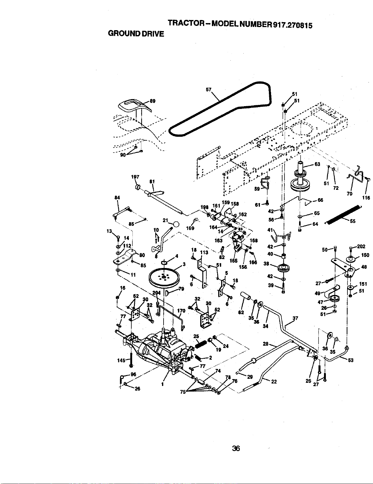
TRACTOR - MODEL NUMBER917.270815
GROUNDDRIVE
57
18 113 "_'."
52
5
18
6
166
156
37
i
26 27
36
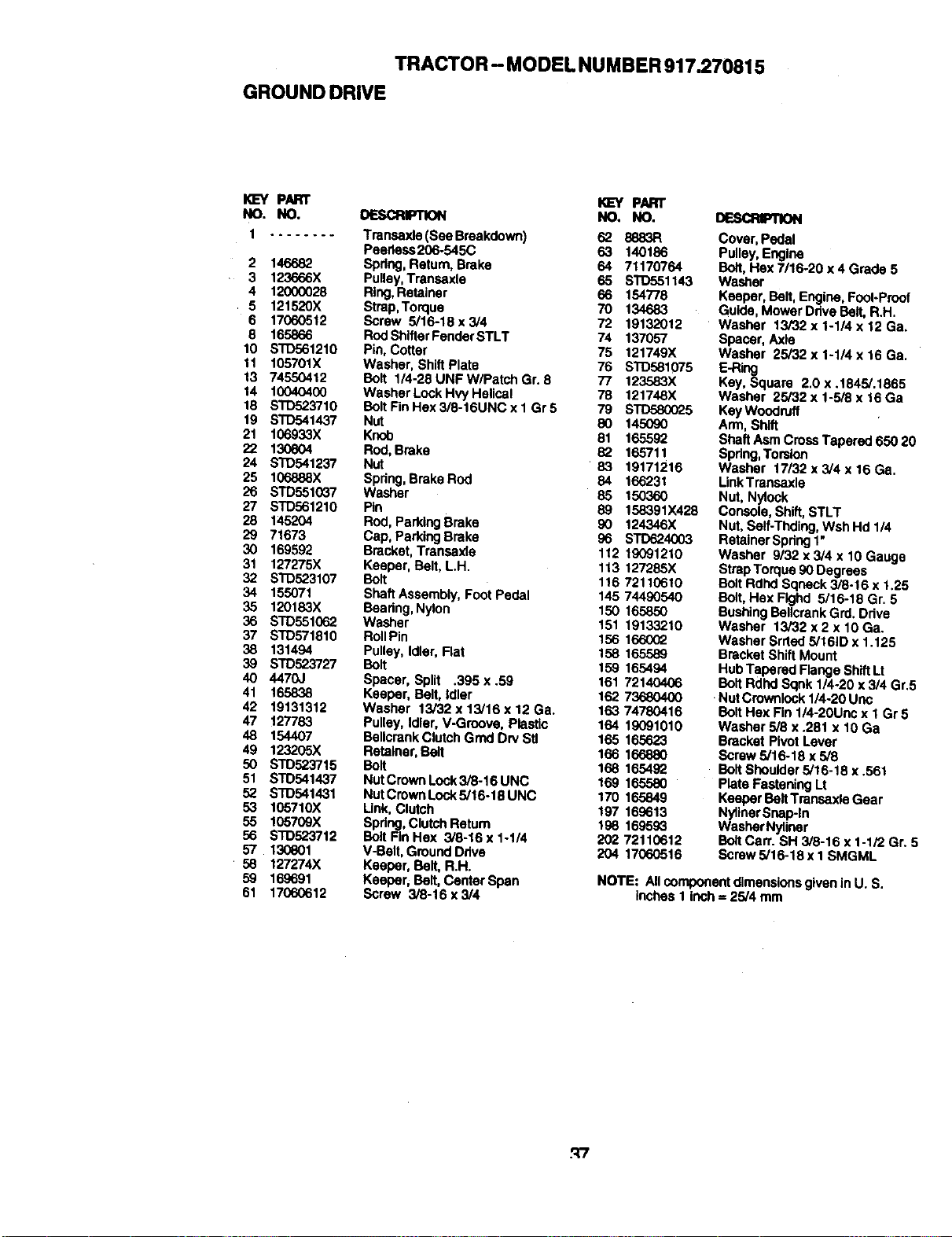
TRACTOR - MODELNUMBER917.270815
GROUNDDRIVE
KEY PART _ PART
NO, NO. OESCR_ NO. NO.
1 ........ Transaxle (See Braakdown) 62 8883R
Peedess206-545C 63 140186
2 146682 Spdng, Ratum, Brake 64 71170764
3 123666X Pulley,Transsxle 65 $113551143
4 12000028 Ring,Retainer 66 154778
5 121520X Strap,Torque 70 134683
6 17060512 Screw 5/16-18 x 3/4 72 19132012
8 165866 RodShllterFenderSTLT 74 137057
10 STD561210 Pin, Cotter 75 121749X
11 105701X Washer, Shift Plate 76 STD581075
13 74550412 Bolt 1/4-28UNFW/PatchGr. 8 77 123583X
14 10040400 Washer Lock Hvy Helical 78 121748X
18 STD523710 BoltFinHex3/6-16UNCx1Gr5 79 STD580025
19 STD541437 Nut 8O 145090
21 106933X Knob 81 165592
22 130804 Rod,Brake 82 165711
24 STD541237 Nut 83 19171216
25 106888X Spdng, BrakeRod 84 166231
26 STD551037 Washer
85 150360
27 STD561210 Pin 89 158391X428
28 145204 Rod, ParklngBrake 90 124346X
29 71673 Cap, Parking Brake 96 STD624(X)3
30 169592 Bracket,Transaxle 112 19091210
31 127275X Keeper, Belt, LH. 113 127285X
32 STD523107 Boll 116 72110610
34 155071 Shaft Assembly, Foot Pedal 145 74490540
35 120183X Bearing, Nylon 150 165850
36 STD551062 Washer 151 19133210
37 STD571810 RollPin 156 166002
38 131494 Pulley, Idler, Flat 158 165589
39 STD523727 Bolt 159 165494
40 4470J Spacer, Split .395 x .59 161 72140406
41 165838 Keeper, Belt, Idler 162 73680400
42 19131312 Washer 13/32x13/16x12Ga. 16374780416
47 127783 Pulley, Idler, V-Groove, Plastic 164 19091010
48 154407 BellcrankClutchGmd Dry Stl 165 165623
49 123205X Retainer, Belt 166 166880
50 STD523715 Boll 168 165492
51 STD541437 NutCrownLock3i8-16UNC 169 165580
52 S'[D541431 NutCrownLock5!16-18UNC 170 165849
53 105710X Link,Clutch 197 169613
55 105709X Spdng,ClutchRotum 198 169593
56 STD523712 BoltFinHox 5/6-16x1-1/4 20272110612
57 130801 V-Belt, Ground Drive 204 17060516
58 127274X Keeper, Bell, R.H.
59 169691 Keeper, Boll, Cantar Span
61 17060612 Screw 3/8-16 x 3/4
DESCRIPTION
Cover, Pedal
Pulley,Engine
Bolt,Hax 7/16-20 x 4 Grade 5
Washer
Keeper, Bolt, Engine, Fool-Proof
Guide, Mower Drive Belt, R.H.
Washer 13/32 x 1-1/4 x 12 Ga.
Spacer, Axle
Washer 25/32 x 1-1/4 x 16 Ga.
E-Ring
Key, Square 2.0 x .1845/.1865
Washer 25/32 x 1-5/8 x 16 Ga
KayWoodruff
Arm, Shift
ShaftAsm CrossTapered 650 20
Spdng,Tomion
Washer 17132x 3/4 x 16 Ga.
LinkTranssxle
Nut, Nylock
Console, Shift, STLT
Nut,Self-Thding, Wsh Hd 1/4
Retainer Spdng1"
Washer 9132x3/4 x 10 Gauge
StrapTorque 90 Degrees
Bolt Rdhd Sqneck 3/8-16 x 1.25
Bolt, Hax Flghd 5/16-18 Gr. 5
BushingBollcrank Grd. Ddve
Washer 13/32 x 2 x 10 Ga.
Washer Srrted 5/161Dx 1.125
Bracket Shift Mount
Hub Tapered Flange ShiftLt
Boll Rdhd Sqnk 114-20x 3/4 Gr.5
Nut Crownlonk1/4o20Unc
Bolt Hex Fin 1/4-20Unc x 1 Gr 5
Washer 5/8 x .281 x 10 Ga
Bracket Pivot Lever
Screw 5/16-18 x 5/8
Boll Shoulder 5/16-18 x .561
Plate Fastening Lt
Keeper Boll Transaxle Gear
Nyllner Snap-In
Washar Nyliner
BoltCarr. SH 3/8-16 x 1-1/2 Gr. 5
Screw 5/16-18 x I SMGML
NOTE: Allcomponent dimensionsgiven in U. S.
Inches 1 inch = 25/4 mm
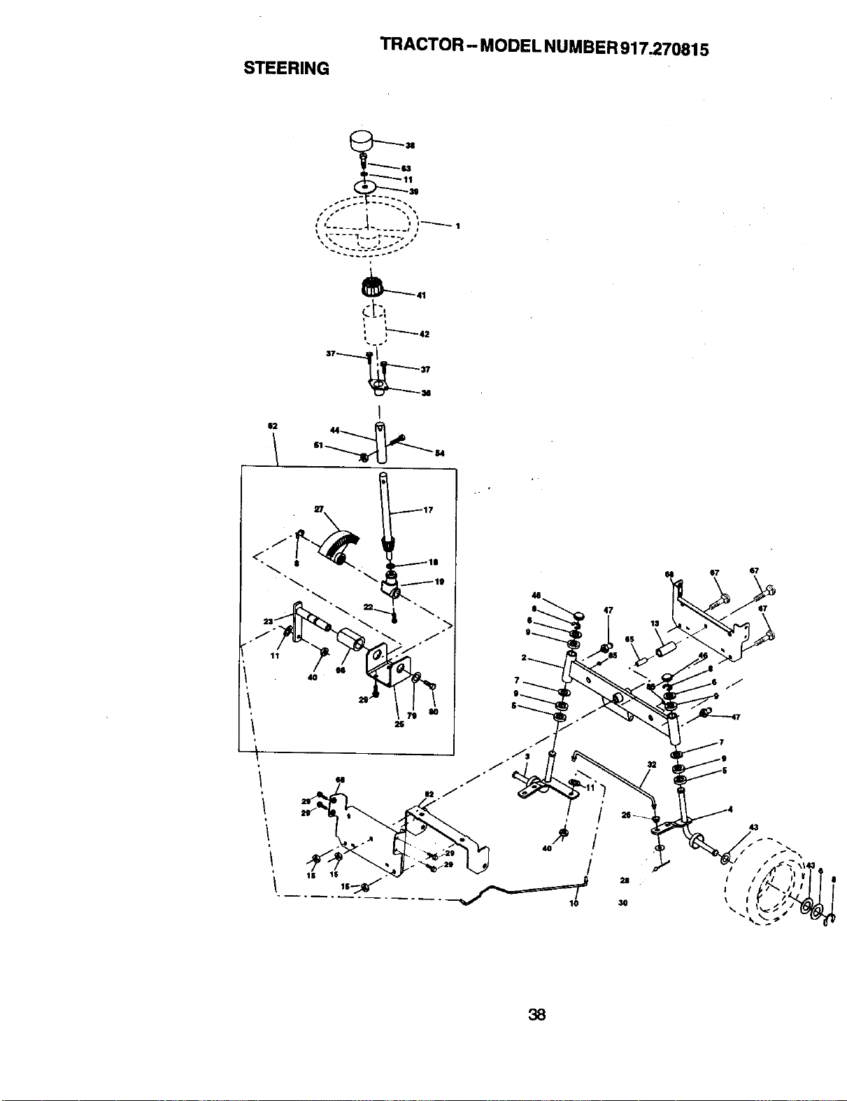
STEERING
TRACTOR - MODEL NUMBER 917.270815
"------ Ikl
t I f"
: "-'-'-'-- I
,"-'--42
I
$2 44
117
4
47
O4 07
87
$7
38

STEERING
TRACTOR -- MODEL NUMBER 917.270815
I_EY P/Urn"
NO. NO. DESCRIPTION
t 139768
2 154427
3 169840
4 169839
5 62661-1
6 121748X
7 19272016
8 12000029
9 3366R
10 169832
11 STD551137
13 136518
15 145212
17 156546
18 57079
19 160395
22 165857
23 165851
25 154406
26 126847X
27 136874
26 19131416
29 1706G612
30 S'rD561210
32 130465
36 155099
37 152927
38 139769
39 19133812
40 STD541537
41 100711L
42 145054X428
43 121749X
44 153720
46 121232X
47 6855M
51 STD541431
54 74780520
62 167902
63 S'_ro23710
65 160367
66 154404
67 72140618
68 169827
79 19132012
80 74950612
82 169835
85 133835
SteedngWheel
AxleAssemblySTMP DroppedSTL
Spindle Assembly,L.H.
Spindle Assembly, R.H.
Beadng, Race, Thrust,Hardened
Washer 25/32 x 1-5/8 x 16 Gauge
Washer 27/32 x 1-1/4 x 16 Gauge
Ring, Klip
Beadng,SteeringColumn
Draglink
Washer, Lock
Spacer, Bearing, Axle
Nut,Hexflange Lock
Shaft Assembly, Steering
Washer, Thrust .515 x .750 x .033
Support, Shaft
ScrewHex WshhdTorx
Pittman Shaft Assembly
Bracket, Steering
Bushing,Link, Drag
Gear, Sector
Washer 13/82 x 7/8 x 16 Gauge
Screw 3/8-16 x 3/4
Pin
Rod,Tie
Bushing, Steedng
Screw
Insert, Steering Wheel
Washer 13/32 x 2-3/8 x 12 Gauge
Gripco Nut
Adaptor, SteeringWheel
Boot, Steedng Shaft
Washer 25/82 x 1-1/4 x 16 Gauge
Extension Shaft Steering LR.LT
Cap, Spindle
Fitting,Grease
Nut LockHex w/Ins. 5/16-18 UNC
BoltFin Hex 5/16-18 UNC x 1-1/4
KitSteedng Asm Service
Bolt, Fin Hex 3/6-16 UNC x 1 Gr 5
Spacer Axle
BearingArmPlttman
BoltRdhd Sg 3/8-16 unc x 2-1/4
Axle, Brace
Washer 13/32 x 1-1/4 x 12 Ga
Bolt Hex Nylon 3/8-16 x 3/4
Bracket Susl3Chassis Front
FastnerChristmasTree
NOTE: All componentdimensionsgiven inU. S.
inches 1 inch = 25/4 mm
39
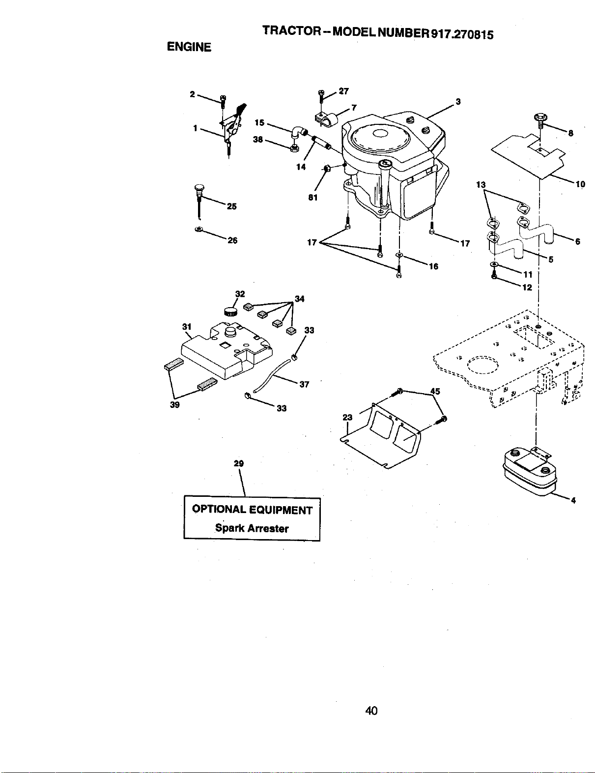
ENGINE
TRACTOR - MODEL NUMBER917.270815
31
39
32
29
t
I OPTIONAL EQUIPMENT pSpark Arrester
/3
13 10
/
40
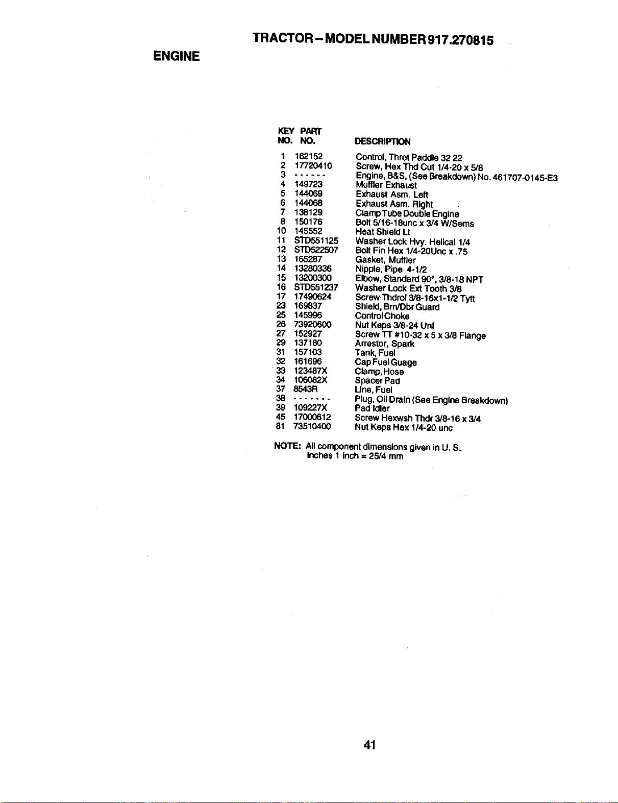
ENGINE
TRACTOR -- MODEL NUMBER 917.270815
KEY PART
NO. NO. DESCRIP;K)N
1 162152
2 17720410
3 °°°---
4 149723
5 144069
6 144068
7 138129
8 150176
10 145552
11 S'rD551125
12 S'1"D522507
13 165287
14 13280336
15 13200300
16 STD551237
17 17490624
23 169837
25 145996
26 73920600
27 152927
29 137180
31 157103
32 161696
33 123487X
34 106082X
37 8543R
38 .......
39 109227X
45 17000612
81 73510400
Control,Throt Paddle 32 22
Screw, Hex Thd Cut 1/4-20 x 5/8
Engine,B&S, (See Breakdown) No.461707-0145-E3
Muffler Exhaust
Exhaust Asm. Left
Exhaust Asm. Right
ClampTube DoubleEngine
Bolt5/16-18unc x 3/4 W/Sems
Heat Shield Lt
Washer Lock Hvy. Helical 1/4
BoltFin Hex 1/4-20Unc x 75
Gasket, Muffler
Nipple, Pipe 4-1/2
Elbow,Standard 90°, 3/8-18 NPT
Washer LockExt Tooth 3/8
ScrewThdrol 3/8-16xi-I/2 Tytt
Shield, BrrdDbrGuard
ControlChoke
Nut Keps 3/8-24 Unf
Screw l-r #1o-32 x 5 x 3/8 Flange
Arrestor, Spark
Tank, Fuet
Cap Fuel Guage
Clamp,Hose
SpacerPad
Line,Fuel
Plug,Oil Drain (See EngineBreakdown)
Ped Idler
Screw Hexwsh Thdr 3/8ol6 x 3/4
Nut Keps Hex 1/4-20 unc
NOTE: All componentdimensionsgiven inU. SL
inches 1 inch = 25/4 mm
41
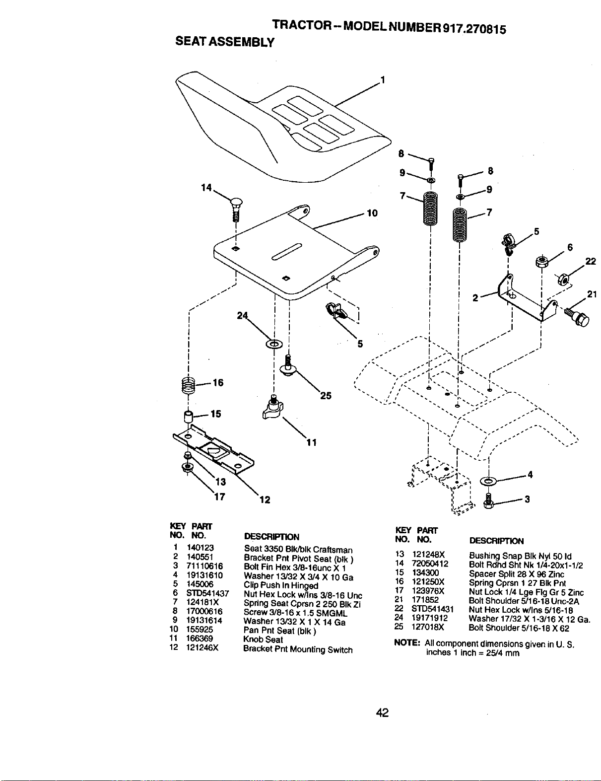
TRACTOR - MODEL NUMBER917.270815
SEATASSEMBLY
lO
I<_EYPART I<LcYPART
NO. NO. DESCRIPTION NO. NO. DESCRIPTION
Seat 3350 BIk/blk Craftsman 13 121248X
Bracket Pnt Pivot Seat (blk) 14 72050412
BoltFin Hex 3/8-16unc X 1 15 134300
Washer 13/32 X 3/4 X 10 Ga 16 121250X
ClipPush In Hinged 17 123976X
Nut Hex Lock w/Ins 3/8-16 Unc 2_. 171852
Spdng Seat Cprsn 2 250 BIkZi 22 STD541431
Screw 3/5-16 x 1,5 SMGML 24 19171912
Washer t3/32 X 1X 14 Ga 25 127018)(
Pan Pnt Seat (blk)
KnobSeat
Bracket Pnt Mounting Switch
1 140123
2 140551
3 71110616
4 19131610
5 145006
6 STD541437
7 124181X
8 17000616
9 19131614
10 155925
11 166369
12 121246X
Busing Snap Blk Ny150 Id
Bolt Rdhd Sht Nk 1/4-20x1-1/2
Spacer Split 28 X 96 Zinc
SpringCprsn t 27 BIk Pot
Nut Lock 1/4 Lge FigGr 5 Zinc
BoltShou|der5/t 6-18 Unc-2A
Nut Hex Lockw/Ins 5/16-18
Washer 17/32 X 1-3/16 X 12 G
BoltShoulder5/16-16 X 62
NOTE: All componentdimensionsgivenin U. S.
inches 1 inch = 25/4 mm
42
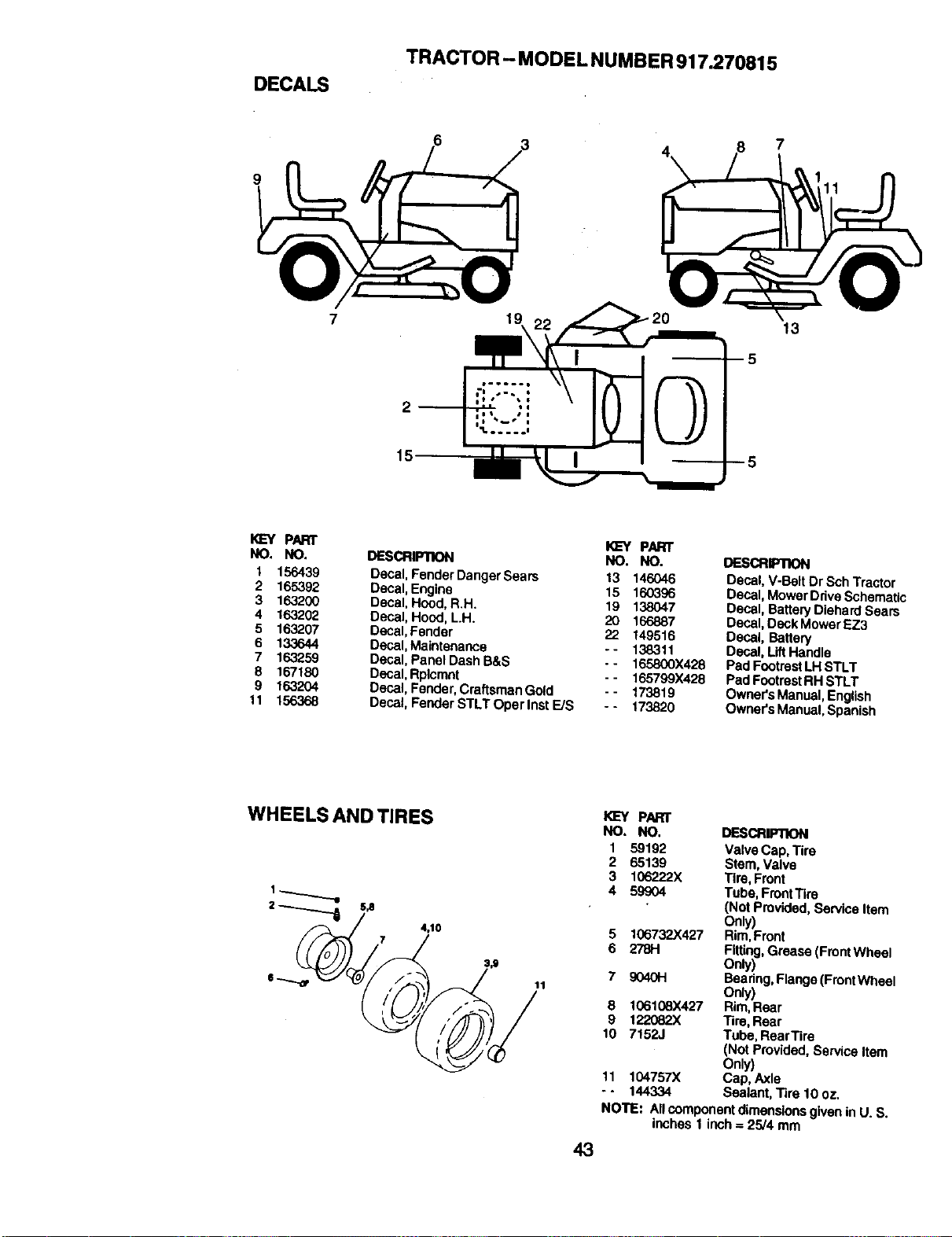
DECALS
TRACTOR - MODEL NUMBER917.270815
7
7
2 --
15
13
I<LW PART
NO. NO.
1 156439
2 165392
3 163200
4 163202
5 163207
6 13,3644
7 163259
8 167180
9 163204
11 156368
KL=YP/I=RT
DESCRIPTION NO. NO.
Decal, Fender Danger Sears 13 146046
Decal, Engine 15 160396
Decal, Hood,R.H. 19 138047
Decal, Hood, L.H. 20 166887
Decal,Fender 22 149516
Decal,Maintenance - - 138311
Decal, Panel Dash B&S .. 165800X428
Decal,Rplcmnt - - 165799X428
Deca_,Fender, CraftsmanGold - - 173819
Decal, Fender STLT Oper Inst E/S - - 173820
DESCRIPTION
Decal, V-Belt Dr Sch Tractor
Decal, Mower Drive Schematic
Decal, BatteryDiehard Sears
Decal, Deck MowerEZ3
Decal, Battery
Decal, LiftHandle
Pad FootrestLH STLT
PadFootrestRH STLT
Owner's Manual, English
Owner's Manual, Spanish
WHEELS AND TIRES
KL=YPART
NO. NO. DESCRIFIION
1 59192 Valve Cap, Tire
2 65139 Stem,Valve
3 106222X Tire, Front
4 59904 Tube, FrontTire
(Not Provided, Service Item
Only)
5 106732X42"/ Rim,Front
6 278H Fitting,Grease (FrontWheel
oR)
7 9040H Bearing, Flange(FrontWheel
Only)
8 106108X427 Rim,Rear
9 122082X Tire, Rear
10 71523 Tube, RearTire
(Not Provided, Service Item
Only)
11 104757X Cap, Axle
- - 144334 Sealant, Tire 10 oz.
NOTE: All componentdimensionsgiven in U. S.
inches 1 inch = 25/4 mm
43
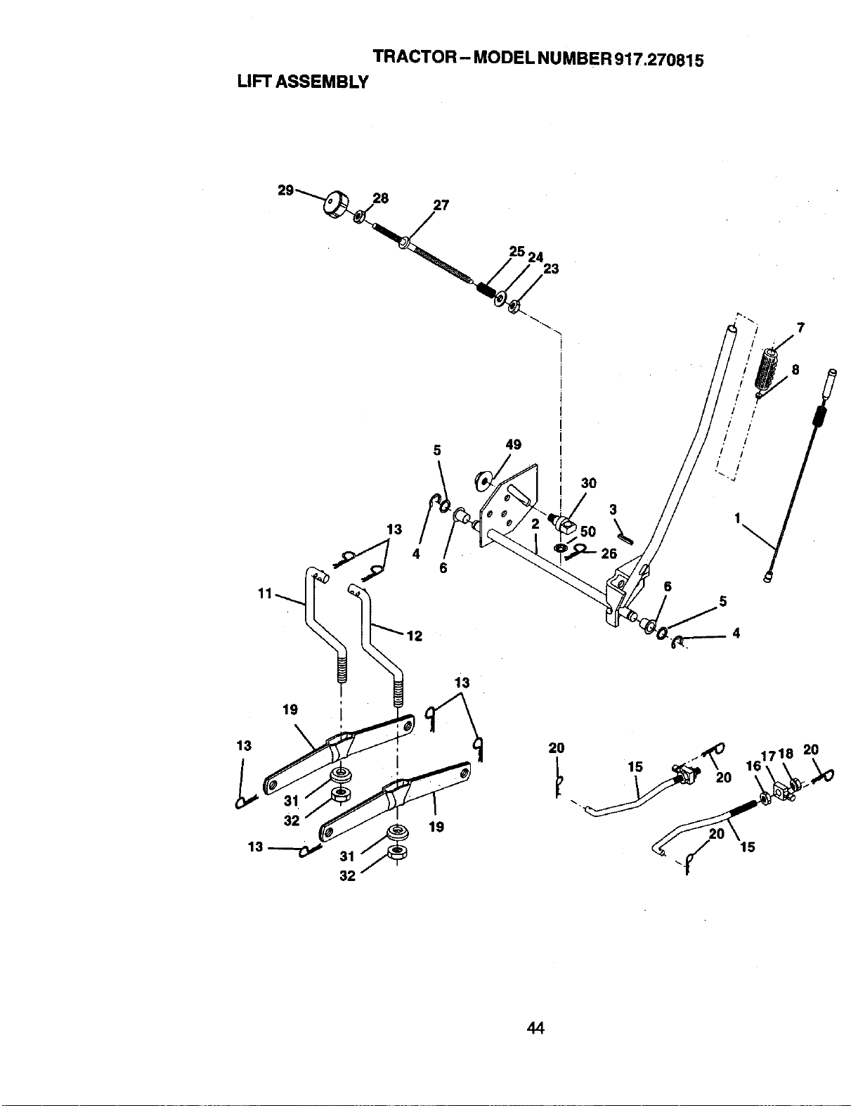
TRACTOR - MODEL NUMBER917.270815
LIFTASSEMBLY
27
25 24
23
7
13
4
49
6
30
3
19
13
32
13 _ 31
32
13
19
20 ./_
d_ _y 15
44
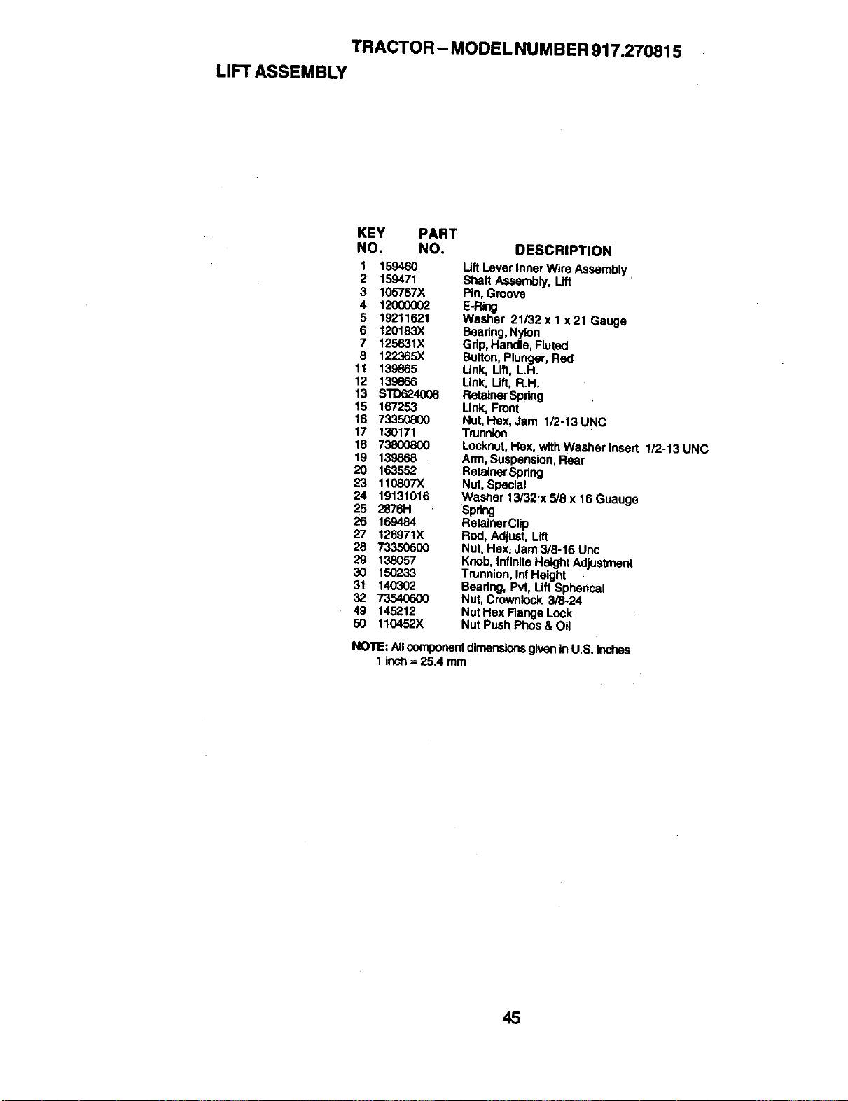
TRACTOR - MODEL NU MBER 917.270815
LIFT ASSEMBLY
KEY PART
NO. NO. DESCRIPTION
1 159460 Lift Lever tnnet Wire Assembly
2 159471 Shaft Assembly, Lift
3 105767X Pin,Groove
4 12000002 E-Ring
5 192"t1521 Washer 21/32 x 1 x 21 Gauge
6 120183X Beadng,Nylon
7 125631X Grip,Handle, F|'ot_
8 122365X Button,Plunger, Red
11 139865 Link, Lift, L.H.
12 139866 Link, Lift, R.H.
13 S'1D624008 RetainerSpdng
15 167253 Link,Front
16 73350800 Nut,Hex, Jam 1/2-13UNC
17 130171 Trunnion
18 73800800 Locknut,Hex, wfthWasherlneert 1/2-13UNC
19 139868 Arm, Suspension,Rear
20 163552 Retainer Spdng
23 110807X Nut,Special
24 19131016 Washer 15/32'x 5/8 x 16 Guauge
25 2876H Spdng
26 169484 RetainerClip
27 126971X Rod, Adjust, Lift
28 73350600 Nut, Hex, Jam 3/8-16 Unc
29 138057 Knob, InfiniteHeight Adjustment
30 150233 Trunnion, InfHe|ght
31 140302 Bearing, Pvt, Lift Spherical
32 73540600 Nut, Crowrdock 5/8-24
. 49 145212 Nut Hex Range Lock
50 110452X Nut PushPhos & Oil
NOTE: AllcomponentdimensionsgiveninU.S. Inches
1inch = 25.4 mm
45
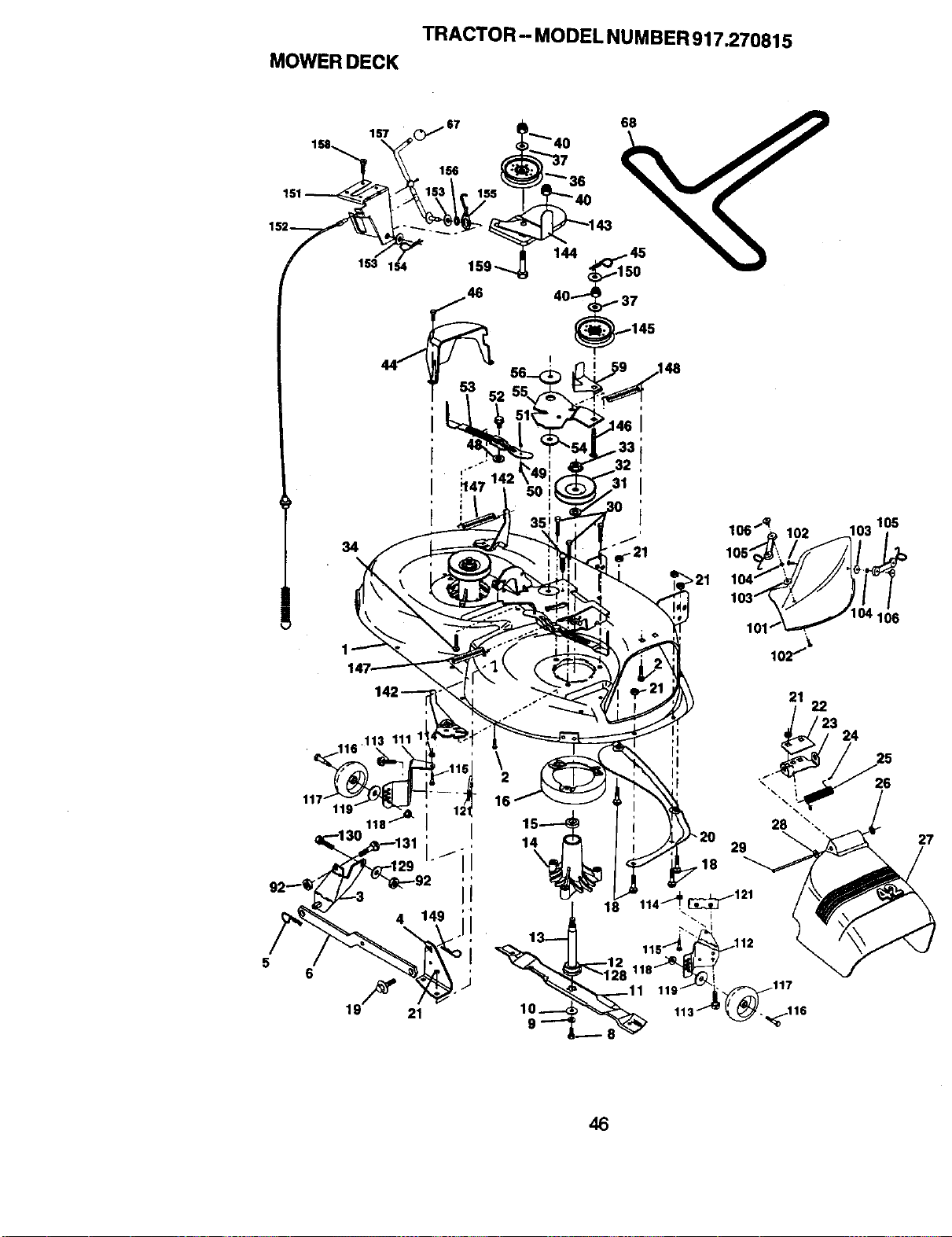
TRACTOR - MODELNUMBER917.270815
MOWERDECK
68
34
i
loe"_^1o2 1o3los
104_/J"_ ,_a"
,o,-,,/y ,,//
101/_,,,_ 104 106
102I_
\
2
16
1
18
29
_117
_116
27
46
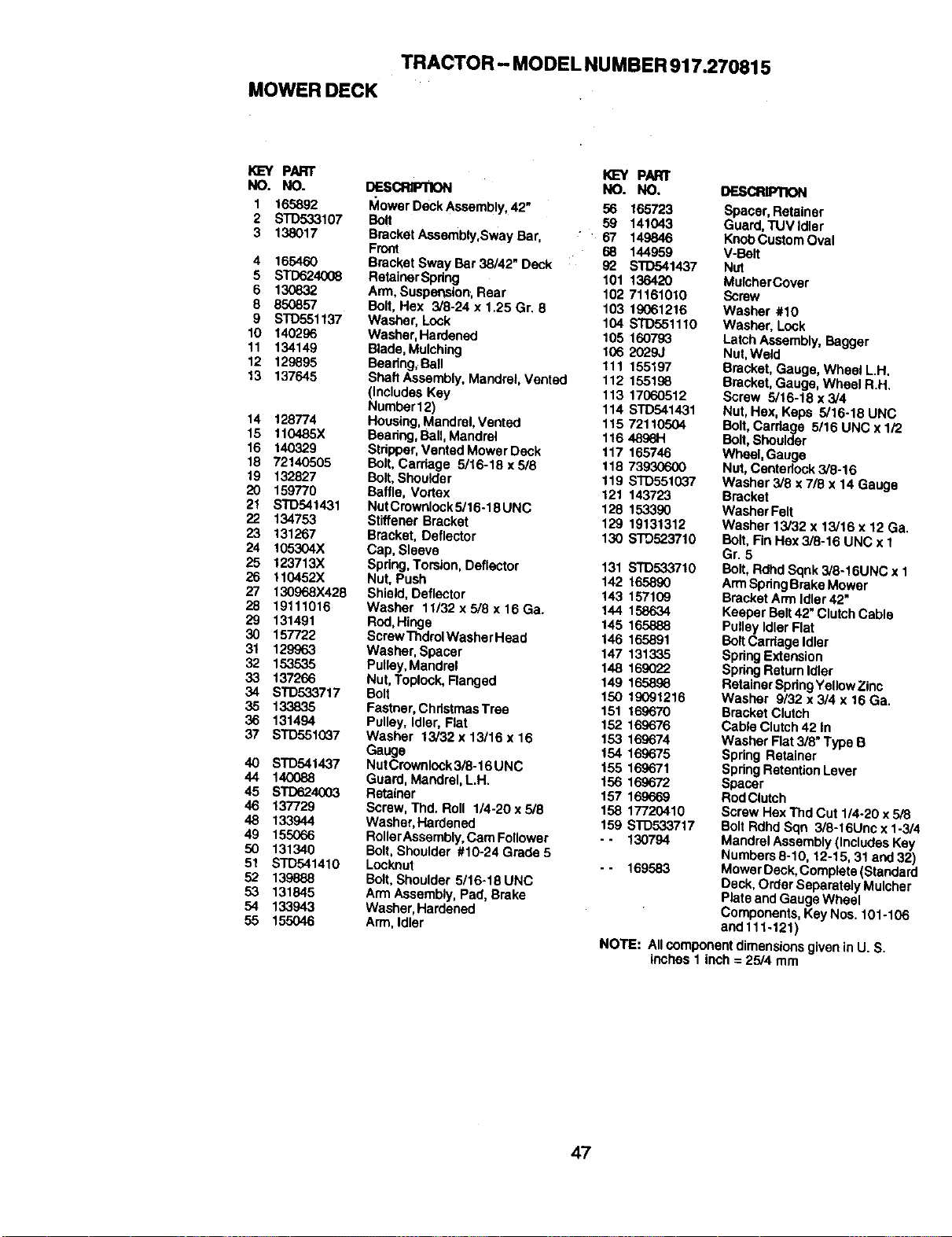
TRACTOR - MODEL NUMBER917.270815
MOWERDECK
PART KEY PART
NO. NO. DESCRIFnON NO. NO.
1 165892 IVlowerDeckAssembly 42" 56 165723
2 STD533107 Bolt 59 141043
3 138017 Bracket Assembly,Sway Bar, " 67 149846
Front 68 144959
4 165460 Bracket Sway Bar 38/42" Deck i 92 STD541437
5 STD624008 RetainerSpdng 101 136420
6 130832 Arm, SuspeP,ston;Rear 102 71161010
8 850857 Bolt, Hex 3/8-24 x 1.25 Gr. 8 103 19061216
9 S'rD551137 Washer, Lock 104 STD551110
10 140296 Washer, Hardened 105 160793
11 134149 Blade,Mulching 106 2029J
12 129_95 Bearing, Bait 111 155197
13 137645 Shaft Assembly, Mandrel, Vented 112 155198
(includes Key 113 17060512
Number12) 114 S'PD541431
14 128774 Housing,Mandrel, Vented 1t5 72110504
15 110485X Beadng,Ball,Mandrel 116_
16 140329 Str_, Vented Mower Deck 117 165746
16 72140505 Bolt,Carriage 5/16-18 x518 118 73930600
19 132827 Bolt,Shoulder 119 STD551G37
20 159770 Baffle, Vortex 121 143723
21 STD541431 NutCmwnlock5/16-18UNC 128 153390
22 134753 Stiffener Bracket 129 19131312
23 131267 Bracket. Deflector 130 s'rD523710
24 105304X Cap, Sleeve
25 123713X Spring,Tomion, Deflector 131 STD533710
26 110452X Nut, Push 142 165890
27 130968X428 Shield, Deflector 143 157109
28 19111016 Washer 11/32xS/8x16Ga. 144 158634
29 131491 Rod,Hinge 145 165888
30 157722 ScrewThdrolWasherHead 146 165891
31 129963 Washer, Spacer 147 131335
32 153535 Pulley,Mandrel 148 169022
33 137266 Nut, Toplock,Flanged 149 165896
34 STD533717 Bolt 150 19091216
35 133835 Fastner, ChristmasTrae 151 169670
36 131494 Pulley, Idler, Rat 152 169676
37 STD551037 Washer 13/32 x13/16 x16 153 169674
Gauge 154 169675
40 S'fD541437 NutCrownlock3/8-16UNC 155 169671
44 140088 Guard, Mandrel, L.H. 156 169672
45 STD624003 Retatner 157 169669
46 137729 Screw, Thd. Roll 1/4-20 x 5/8 158 17720410
48 133944 Washer, Hardened 159 STD533717
49 155066 RollerAssembly,Cam Follower -- 130794
50 131340 Bolt, Shoulder #10-24 Grede 5
51 STD541410 Locknut -- 169583
52 139888 Bolt, Shoulder 5/16-18 UNC
53 131845 Arm Assembly, Pad, Brake
54 133943 Washer, Hardened
55 155046 Arm, Idler
DESCRIP'_:)N
Spacer, Retainer
Guard, TUV Idler
KnobCustom Oval
V-Belt
Nut
MulcherCover
Screw
Washer #10
Washer, Lock
Latch Assembly, Bagger
Nut,Weld
Bracket, Gauge, Wheel L.H,
Bracket, Gauge, Wheel R H.
Screw 5/16-18 x 3/4
Nut, Hex, Keps 5/16-18 UNC
Bolt,Carriage 5/16 UNC x 1/2
Bolt, Shoulder
Wheel, Gauge
Nut,Centedock 3/8-16
Washer 3/8 x 7/8 x 14 Gauge
Bracket
Washer Felt
Washer 13/32 x 13/16 x 12 Ga.
Bolt. Fin Hex3/8-16 UNC x 1
Gr 5
Bolt, Rdhd Sqnk 3/8-16UNC x 1
ArmSpringBrake Mower
Bracket Arm Idler42"
Keeper Belt42" ClutchCable
PulleyIdler Flat
Bolt Carriage Idler
SpringExtension
SpringReturn Idler
Retainer SpringYellowZinc
Washer 9/32 x 3/4 x 16 Ga.
Bracket Clutch
Cable Clutch42 In
Washer Flat 3/8" Type B
Spring Retainer
Spring RetentionLever
Spacer
RodClutch
Screw Hex Thd Cut 114-20x 5/8
BoltRdhd Sqn 3/8-16Unc x 1-3/4
Mandrel Assembly(Includes Kay
Numbers 8-10, 12-15, 31 end 32)
Mower Deck,Complete (Standard
Deck, Order Separately Mulcher
Plate and Gauge Wheel
Components, Key Nos. 101-106
and 111-121)
NOTE: All componentdimensionsgiven in U. S
inches 1 inch = 25/4 mm
47
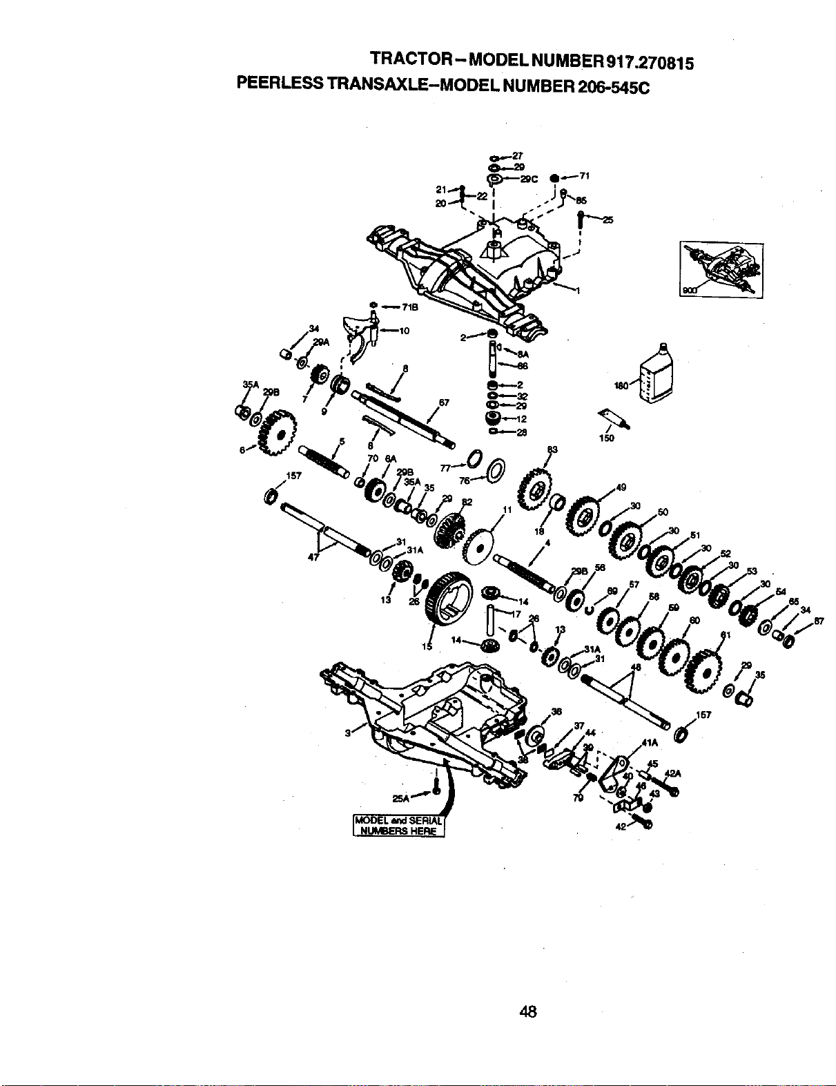
TRACTOR - MODEL NUMBER 917.270815
PEERLESS TRANSAXLE-MODEL NUMBER 206-545C
157
O _ 71B
8
706A
I
150
47
48
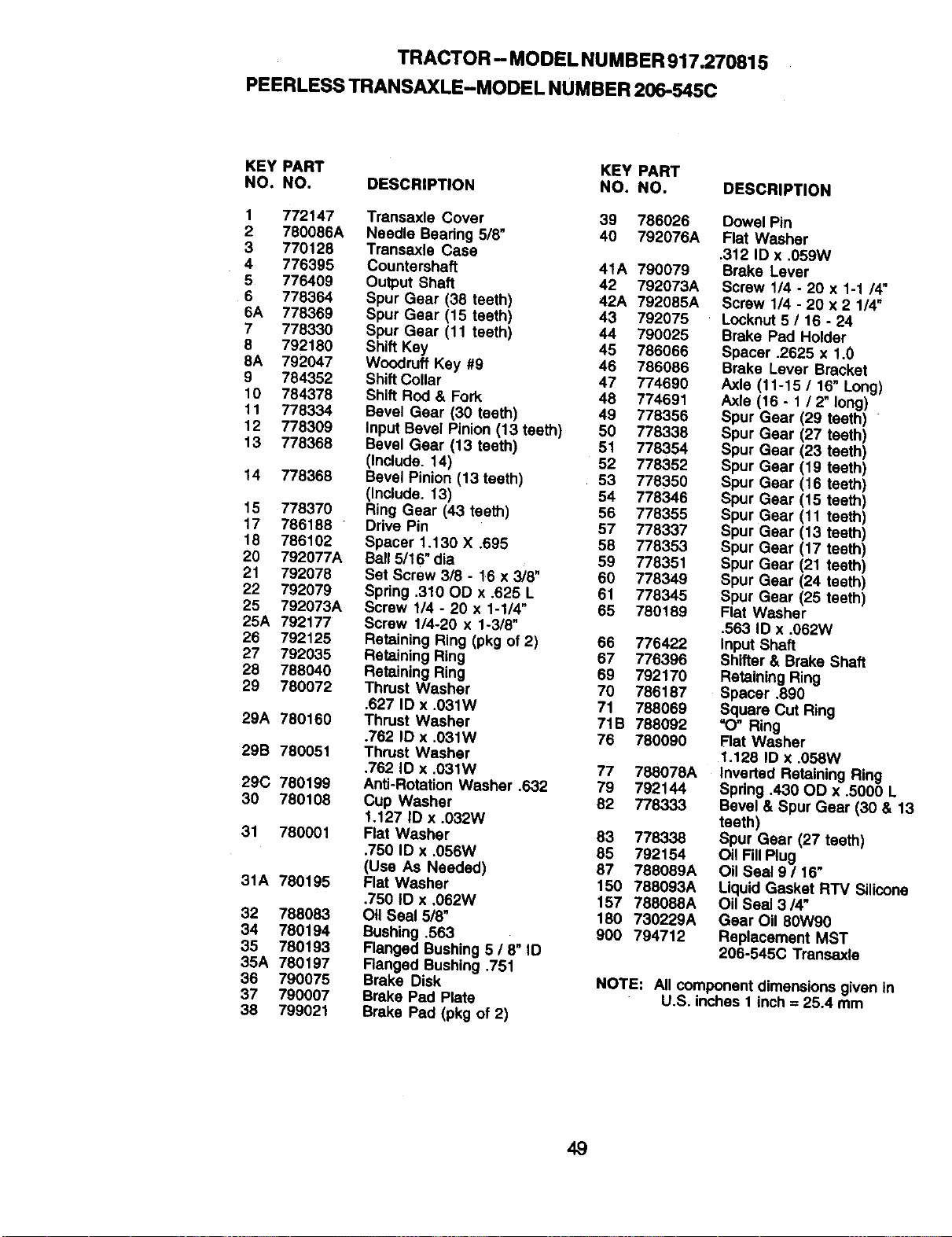
TRACTOR - MODELNUMBER917.270815
PEERLESSTRANSAXLE-MODEL NUMBER206-545C
KEY PART KEY PART
NO. NO. DESCRIPTION NO. NO.
1 772147 Trensaxle Cover 39 786026
2 780086A Needle Bearing 5/8" 40 792076A
3 770128 Transaxle Case
4 776395 Countershaft 41A 790079
5 776409 Output Shaft 42 792073A
6 778364 Spur Gear (38 teeth) 42A 792085A
6A 778369 Spur Gear (15 teeth) 43 792075
7 778330 Spur Gear (11 teeth) 44 790025
8 792180 Shift Key 45 786066
8A 792047 Woodruff Key #9 46 786086
9 784352 Shift Collar 47 774690
10 784378 Shift Rod & Fork 48 774691
11 778334 Bevel Gear (30 teeth) 49 778356
12 778309 Input Bevel Pinion (13 teeth) 50 778338
13 778368 Bevel Gear (13 teeth) 51 778354
(Include. 14) 52 778352
14 7-/8368 Bevel Pinion (13 teeth) 53 778350
(Include. 13) 54 778346
15 778370 Ring Gear (43 teeth) 56 778355
17 786188 Drive Pin 57 778337
18 786102 Spacer 1,130 X .695 58 778353
20 792077A Ball 5/16" dia 59 778351
21 792078 Set Screw 3/8 - 16 x 3/8" 60 778349
22 792079 Spring .310 OD x .625 L 61 778345
25 792073A Screw 1/4 - 20 x 1-1/4" 65 780189
25A 792177 Screw 1/4-20 x 1-3/8"
26 792125 Retaining Ring (pkg of 2) 66 776422
27 792035 Retaining Ring 67 776396
28 788040 Retaining Ring 69 792170
29 780072 Thrust Washer 70 786187
.627 ID x .031W 71 788069
29A 780160 Thrust Washer 71B 788092
.762 ID x .031W 76 780090
29B 780051 Thrust Washer
.762 ID x .031W 77 788078A
29C 780199 Anti-Rotation Washer .632 79 792144
30 780108 Cup Washer 82 778333
1.127 ID x .032W
31 780001 Flat Washer 83 778338
.750 ID x ,056W 85 792154
(Use As Needed) 87 788089A
31A 780195 Flat Washer 150 788093A
.750 ID x ,062W 157 788088A
32 788083 Oil Seal 518_ 180 730229A
34 780194 Bushing .563 900 794712
35 780193 Flanged Bushing 6 / 8" _D
35A 780197 Ranged Bushing .751
36 790075 Brake Disk
37 790007 Brake Pad Plate
38 799021 Brake Pad (pkg of 2)
DESCRIPTION
Dowel Pin
Flat Washer
.312 ID x .059W
Brake Lever
Screw 114- 20 x 1-1 14"
Screw 1/4 - 20 x 2 1/4"
Locknut 5 / 16 - 24
Brake Pa_ Holder
Spacer .2625 x 1.0
Brake Lever Bracket
Axle (11-15 / 16" Long)
Axle (16- 1 12" long)
Spur Gear (29 teeth)
Spur Gear (27 teeth)
Spur Gear (23 teeth)
Spur Gear (19 teeth)
Spur Gear (16 teeth)
Spur Gear (15 teeth)
Spur Gear (11 teeth)
Spur Gear (13 teeth)
Spur Gear (17 teeth)
Spur Gear (21 teeth)
Spur Gear (24 teeth)
Spur Gear (25 teeth)
Flat Washer
.563 ID x .062W
Input Shaft
Shifter & Brake St_ft
Retaining Ring
Spacer .890
Square Cut Ring
=O" Ring
Flat Washer
1.128 ID x .058W
Inverted Retaining Ring
Spring .430 OD x .5000 L
Bevel & Spur Gear (30 & 13
teeth)
Spur Gear (27 teeth)
Oil FillPlug
Oil Seal 9 / 16"
Liquid Gasket RTV Silicone
Oil Seal 3/4"
Gear Oil 80W90
Replacement MST
206-545(3 Transaxle
NOTE: All component dimensions given in
U.S. inches 1inch = 25.4 mm
49
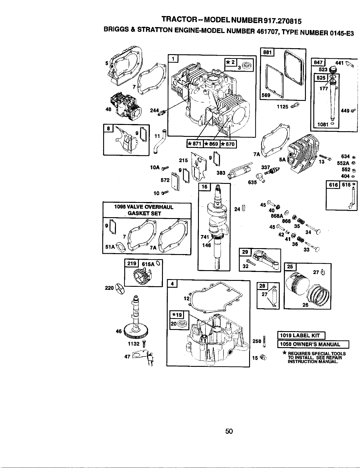
TRACTOR - MODEL NUMBER 917.270815
BRIGGS & STRATTON ENGINE-MODEL NUMBER 461707, TYPE NUMBER 0145-E3
I 1125
46
1132
26
634 o
552A
552
404 o
2581 I1018LASELKrrI
I 1058 OWNER'S MANUAL I
_k REQUIRES SPECIALTOOLS
15 _ TOINSTALL.SEEREPAIR
INSTRUC'nONMANUAL.
50
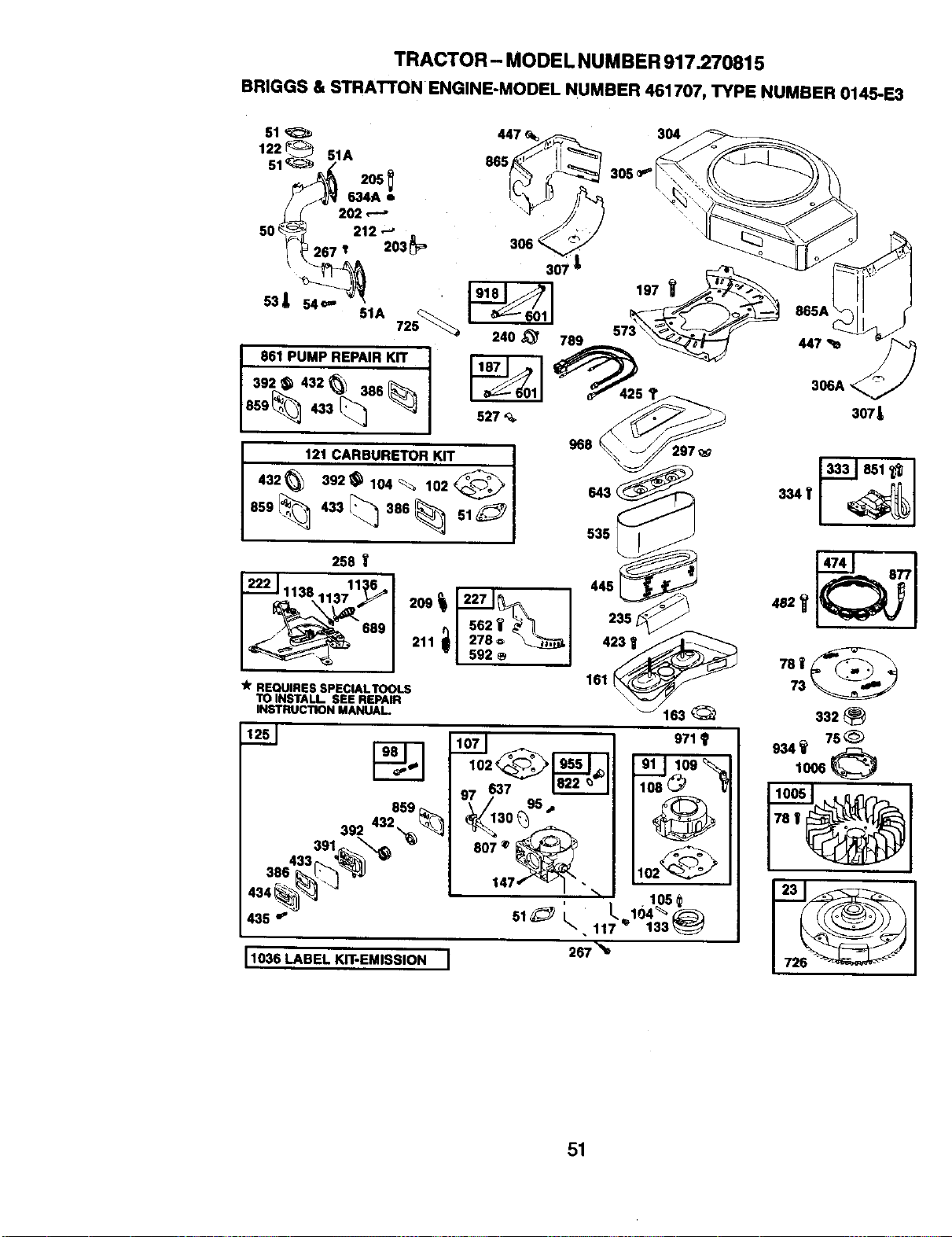
TRACTOR- MODEL NUMBER 917.270815
BRIGGS & STRATrON ENGINE-MODEL NUMBER 461707, TYPE NUMBER 0145-E3
51
122 { 51A
205
634A •
202 ,-'-"
50 _ 212 --_
£
267 I 203 _'
53A 54_"
51A 725_
861 PUMP REPAIR KIT I
392_ 432 _ 386
[
859_ 433 _
121 CARBURETOR KIT I
I ,32 3+2 104.102 I
1859/_ 433/_ 386_ o1 1
240 _ 789
527 '_
968 297
643 (
535
258
1138 11:_6_,
689 n I 562 _ _ _ I
211 Ill 278,, _l
"Im+ I
TOINSTALL SEEREPAIR
INSTRUCTIONMANUAl.
)
435 _ 51 _ I_,
11036 LABEL KIT-EMISSION I 267
51
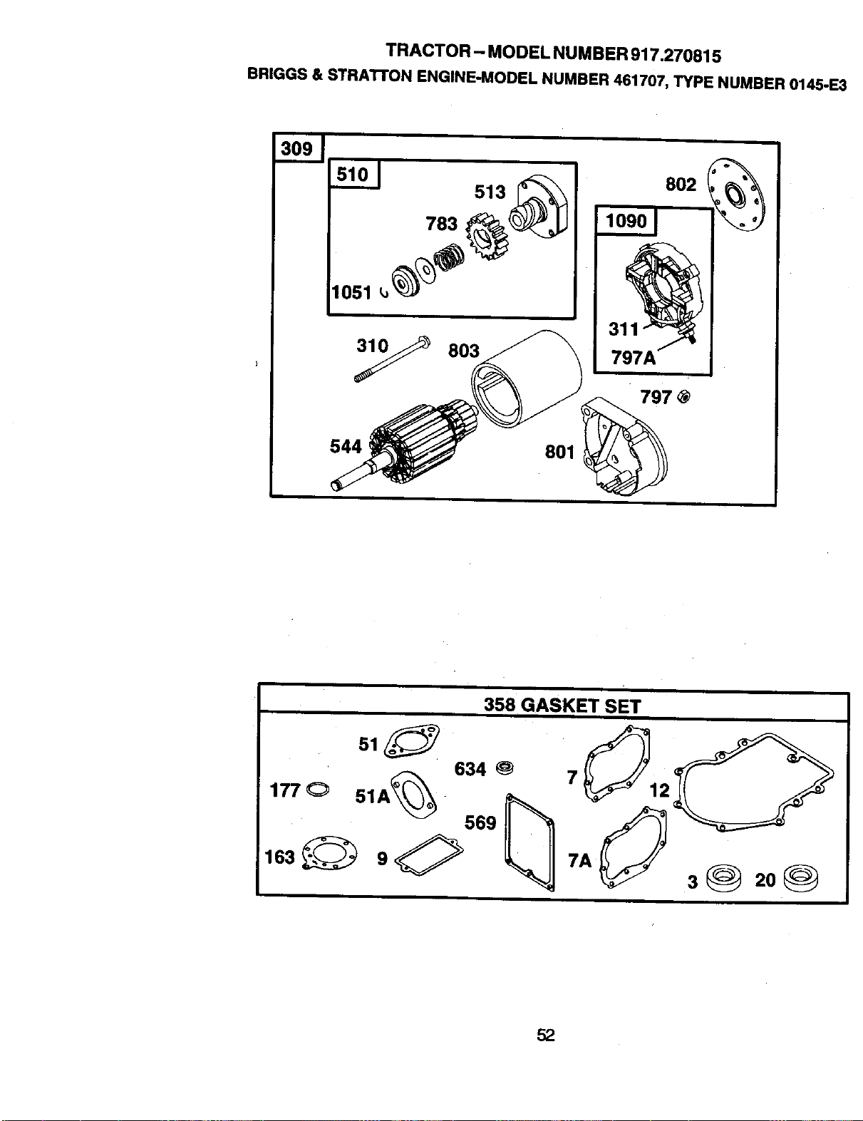
TRACTOR - MODEL NUMBER 917.270815
BRIGGS&STRA'I-FONENGINE-MODEL NUMBER461707,TYPE NUMBER0145-E:
783
1051
544
513
803
3,
797A
797 @
801
358 GASKET SET
r:_ 634
177 O 51A____
5,2
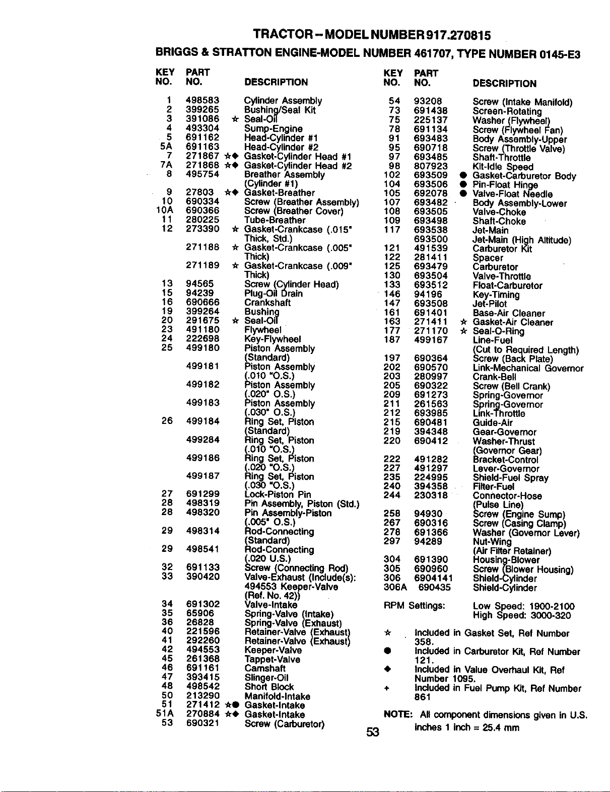
TRACTOR - MODEL NUMBER 917.270815
BRIGGS& STRATTON ENGINE-MODELNUMBER 461707, TYPE NUMBER0145-E3
KEY PART KEY PART
NO. NO. DESCRIPTION NO. NO. DESCRIPTION
1 498583
2 399265
3 391086
4 493304
5 691162
5A 691163
7 271867
7A 271868
8 495754
9 27803
10 690334
10A 690366
11 280225
12 273390
271188
271189
13 94565
15 94239
16 690666
19 399264
20 291675
23 491180
24 222698
25 499180
499181
499182
499183
26 499184
499284
499186
499187
27 691299
28 498319
28 498320
29 498314
29 498541
32 691133
33 390420
34 691302
35 65906
36 26828
40 221596
41 292260
42 494553
45 261368
46 691161
47 393415
48 498542
50 213290
51 271412
51A 270884
53 690321
Cylinder Assembly 54 93208 Screw (Intake Manifold)
Bushing/Seal Kit 73 691438 Screen-Rotating
_r Seal-O=3 75 225137 Washer (Flywheel)
Sump-Engine 78 691134 Screw (Flywheel Fan)
Head-Cylinder #1 91 693483 Body Assembly-Upper
Head-Cylinder #2 95 690718 Screw (Throttle Valve)
•tr<l, Gasket-Cylinder Head #1 97 693485 Shaft-Throttle
-tr<) Gasket-Cylinder Head #2 98 807923 Kit-Idle Speed
Breather Assembly 102 693509 • Gasket-Carburetor Body
(Cylinder #1) 104 693506 • Pin-Float Hinge
-tr• Gasket-Breather 105 692078 • Valve-Float Needle
Screw (Breather Assembly) 107 693482 . Body Assembly-Lower
Screw (Breather Cover) 108 693505 Valve-Choke
Tube-Breather 109 693498 Shaft-Choke
-tr Gasket-Crankcase (.015" 117 693538 Jet-Main
Thick, Std.) 693500 Jet-Main (High Altitude)
Gasket-Crankcase (.005" 121 491539 Carburetor Kit
Thick) 122 281411 Spacer
Gasket-Crankcase (.009" 125 693479 Carburetor
Thick) 130 693504 Valve-Throttle
Screw (Cylinder Head) 133 693512 Float-Carburetor
Plug-Oil Drain 146 94196 Key-Timing
Crankshaft 147 693508 Jet-Pilot
Bushing 161 691401 Base-Air Cleaner
_r Seal-Oil 163 271411 _r Gasket-Air Cleaner
Flywheel 177 271170 _ Seal-O-Ring
Key-Flywheel 187 499167 Line-Fuel
Piston Assembly _Cut to Required Length)
(Standard) 197 690364 _crew (Back Plate)
Piston Assembly 202 690570 Link-Mechanical Govemor
(.010 =O.S.) 203 280997 Crank-Bell
Piston Assembly 205 690322 Screw (Bell Crank)
_.020" O.S.) 209 691273 Spring-Governor
Piston Assembly 211 261563 Spring-Governor
Link-Throttle_i030" O.S.) 212 693985
ng Set, Piston 215 690481 Guide-Air
(Standard) 219 394348 Gear-Governor
Ring Set, Piston 220 690412 Washer-Thrust
(.010 "O.S._ (Governor Gear)
Ring Set, Piston 222 491282 Bracket-Control
(.020 "O.S.) 227 491297 Laver-Governor
Ring Set, Piston 235 224995 Shield-Fuel Spray
(.030 =O.S.) 240 394358 Filter-Fuel
Lock-Piston Pin 244 230318 Connector-Hose
Pin Assembly, Piston (Std.) (Pulse Une)
Pin Assembly-Piston 258 94930 Screw (Engine Sump)
(.005" O.S.) 267 690316 Screw (Casing Clamp)
Rod-Connecting 278 691366 Washer (Governor Lever)
_Standard) 297 94289 Nut-Wing
od-Connecting (Air Filter Retainer)
(.020 U.S.) 304 691390 Housing-Blower
Screw(Connecting ROd) 305 690960 Screw (Blower Housing)
Valve-Exhaust (Include(s): 306 6904141 Shield-Cylinder
494553 Keeper-Valve 306A 690435 Shield-Cylinder
(Ref. No, 42))
Valve-Intake RPM Settings: Low Speed: 1900-2100
Spring-Valve (Intake) High Speed: 3000-320
Spring-Valve (Exhaust)
Retainer-Valve (Exhaust) _ Included in Gasket Set, Ref Number
Retainer-Valve (Exhaust) 358.
Keeper-Valve • Included in Carburetor Kit, Ref Number
Tappet-Valve 121.
Camshaft • Included in Value Overhaul Kit, Ref
Slinger-Oil Number 1095.
Short Block + Included in Fuel Pump Kit, Ref Number
Manifold-Intake 861
_• Gasket-Intake
.tr• Gasket-Intake NOTE: All component dimensions given in U.S,
Screw (Carburetor) 53 inches 1 inch = 25.4 mm
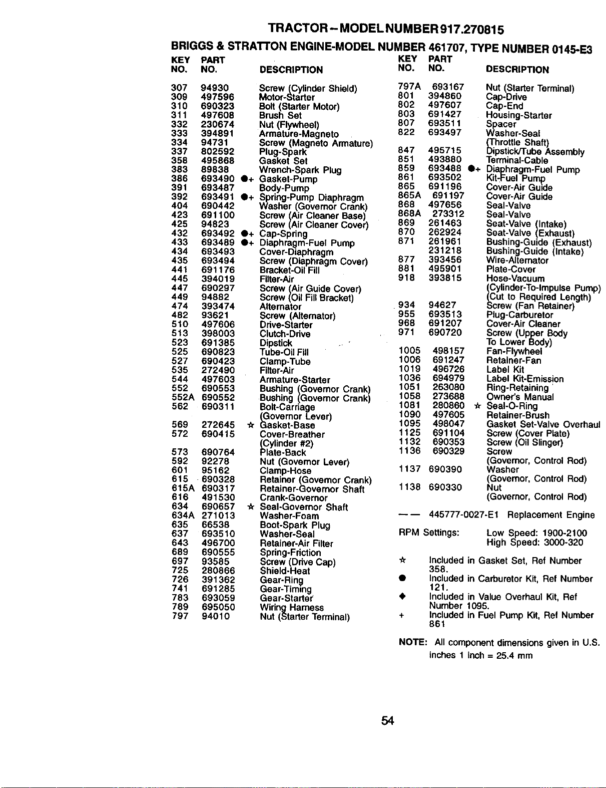
TRACTOR - MODEL NU MBER 917.270815
BRIGGS & STRA'n'ON ENGINE-MODEL NUMBER 461707, TYPE NUMBER 014,5-E_
KEY PART KEY PART
NO. NO. DESCRIPTION NO. NO. DESCRIPTION
307 94930
309 497596
310 690323
311 497608
332 230674
333 394891
334 94731
337 802592
358 495868
383 89838
386
391
392
404
423 691100
425 94823
432 693492
433 693489
434 693493
435 693494
441 691176
445 394019
447 690297
449 94882
474 393474
482 93621
510 497606
613 398003
523 691385
525 690823
527 690423
535 272490
544 497603
552 690553
552A 690552
562 690311
Screw(Cylinder Shield) 797A 693167
Motor-Starter 801 394860
Bolt (S_rter Motor) 802 497607
Brush Set 803 691427
Nut (Flywheel) 807 693511
Armature-Magneto 822 693497
Screw (Magneto Armature)
Ptug-Spa_ 847 495715
Gasket Set 851 493880
Wrench-Spark Plug 859 693488
861 693502
865 691196
865A 691197
868 497656
868A 273312
869 261463
870 262924
871 261961
231218
877 393456
881 495901
918 393815
693490 O+ Gasket-Pump
693487 Body-Pump
693491 O+ Spring-Pump Diaphragm
690442 Washer (GovernorCrank)
569 272645
572 690415
573 690764
592 92278
601 95162
615 690328
615A 690317
616 491530
634 690657
634A 271013
635 66538
637 693510
643 496700
689 690555
697 93585
725 280866
726 391362
741 691285
783 693059
789 695050
797 94010
Screw (Air Cleaner Base)
Screw(Air Cleaner Cover)
O+ Cap-Spring
O+ Diaphragm-Fuel Pump
Cover-Diaphragm
Screw (Diaphragm Cover)
Bracket-OilFill
Filter-Air
Screw (AirGuide Cover)
Screw (OitFLItBracket
Alternator
Screw (Alternator)
Drive-Starter
C4utch-Dr_ve
Dipstick
Tube-OilFill
Clamp-Tube
Filter-Air
Armature-Starter
Bushing (Govemor Crank)
Bushing (Govemor Crank)
Bolt-Carriage
(GovernorLever)
_r L_asket-Base
Cover-Breather
_lYtinder #2)
ate-Back
Nut (Governor Lever)
Clamp-Hose
Retainer (GovernorCrank)
Retainer-Governor Shaft
Crank-Governor
Seal-Governor Shaft
Washer-Foam
Boot-Spark Plug
Washer-Seal
Retainer-AirFilter
Spring-Friction
Screw (Ddve Cap)
Shield-Heat
Gear-Ring
Gear-Timing
Gear-Starter
Wiring Harness
Nut (Starter Terminal)
934 94627
955 693513
968 691207
971 690720
1005 498157
1006 691247
1019 496726
1036 694979
1051 263080
1058 273688
1081 280860
1090 497605
1095 498047
1125 691104
1132 690353
1136 690329
1137 690390
1138 690330
Nut (StarterTerminal)
Cap-Drive
Cap-End
Housing-Starter
Spacer
Washer-Seal
_ihrottle Shaft)
pstickKubeAssembly
Terminal-Cable
O+ Diaphragm-FuelPump
Kit-FuelPump
Cover-Air GUide
Cover-AirGuide
Seal-Valve
Seal-Valve
Seat-Valve (Intake)
Seat-Valve (Exhaust)
Bushing-Guide(Exhaust)
Bushing-Guide(Intake)
Wire-Alternator
Plate-Cover
Hose-Vacuum
Cylinder-To-lmpulsePurr
ut to Required Length)
crew (Fan Retainer)
Plug-Carburetor
Cover-AirCleaner
Screw (Upper Body
To Lower Body)
Fan-Flywheel
Retainer-Fan
Label Kit
Label Kit-Emission
Ring-Retaining
Owner's Manual
-_ Seal-O-Ring
Retainer-Brush
Gasket Set-Valve Overh;
Screw (Cover Plate)
Screw (OilSlinger)
Screw
(Govemor, ControlRod)
Washer
(Govemor, ControlRod)
Nut
(Governor,Control Rod)
---- 445777-0027-E1 Replacement Engi_
RPM Settings: Low Speed: 1900-2100
High Speed: 3000-320
_r
+
Included in Gasket Set, Ref Number
358.
Includedin CarburetorKit, Ref Numbeq
121.
tnctudedin Value Overhaul Kit, Ref
Number 1095.
Includedin Fuel Pump Kit, Ref Numbe
861
NOTE: All component dimensions given in U
inches 1 inch = 25.4 mm
54

SUGGESTED GUIDE FOR SIGHTING SLOPES FOR SAFE OPERATION
SIGHTING
GUIDE
ONLY RIDE UP AND DOWN HILL,
NOT ACROSS HILL
!
Operate your Tractor up and down the face of elopes (not I
greater than 15 ), never across the face. Make turns gradu-
I
ally to prevent tipping or loss of control. Exercise extreme
caution when changing direction on slopes.

For in-home major brand repair service:
Call 24 hours a day, 7 days a week
1-800-4-MY-HOME" (1-800-469-4663)
Para pedir servicio de reparaci6n a domiciUo
1-800-676-5811
In Canada for all your service and parts needs call
Au Canada pour tout le service ou les pi_ces
1-600-665-4455
For the repair or replacement parts you need:
Call 6 am - 11 pm CST, 7 days a week
PartsDirects"
1-800-366-PART (1-800-366-7278)
Para ordenar piezas con entrega a domicilio
1-800-659-7084
For the location of a Sears Parts and Repair Center
in your area:
Call 24 hours a day, 7 days a week
1-800-488-1222
For information on purchasing a Sears Maintenance
Agreement or to inquire about an existing Agreement:
Call 9 am - 5 pro, Monday - Saturday
1-800-827-6655
p_
8EARS
HomeCentral SM
173819 12.20.99 MH Printed in U.S.A.