Loading ...
Loading ...
Loading ...
Note:Manyoftheillustrationsinthismanualshow
onlyportionsofyourcompoundmitersaw.Thisis
intentionalsothatwecanclearlyshowpointsbeing
madeintheillustrations,Neveroperateyoursaw
withoutall guards securely in place and in good
operating condition,
CUTTING A SLOT IN THE ZERO
CLEARANCE THROAT PLATE
In order to use your compound miter saw, you must
cut a slot through the zero clearance throat plate to
allow for blade clearance. To cut the slot, set your
saw at 0 degrees miter, turn saw on and allow the
blade to roach full speed, then carefully make a
straight cut as far as it will go through the throat plate.
Turn your saw off and allow the blade to come to a
complete stop before raising the saw arm.
Next, adjust the bevel angle to 45 degrees, turn your
saw on and allow the blade to reach full speed, then
carefully make another cut through the zero clearance
throat plate. The throat plate will then be wide enough
to allow the blade to pass through itat any angle from
0 to 45 degrees.
SQUARING THE MITER TABLE
TO THE FENCE
See Figures 13 - 16.
• Unplug your saw.
WARNING: Failure to unplug your saw could
m
result in accidental starting causing possible
serious personal injury.
• Push down on the saw arm and pull out the lock
pin to release the saw arm.
• Raise saw arm to its full raised position.
• Loosen the miter lock handle approximately one-
half turn.
• Depress the miter lock plate and rotate the miter
table until the pointer on the control arm is posi-
tioned at O°.
• Release the miter lock plate and securely tighten
the miter lock handle.
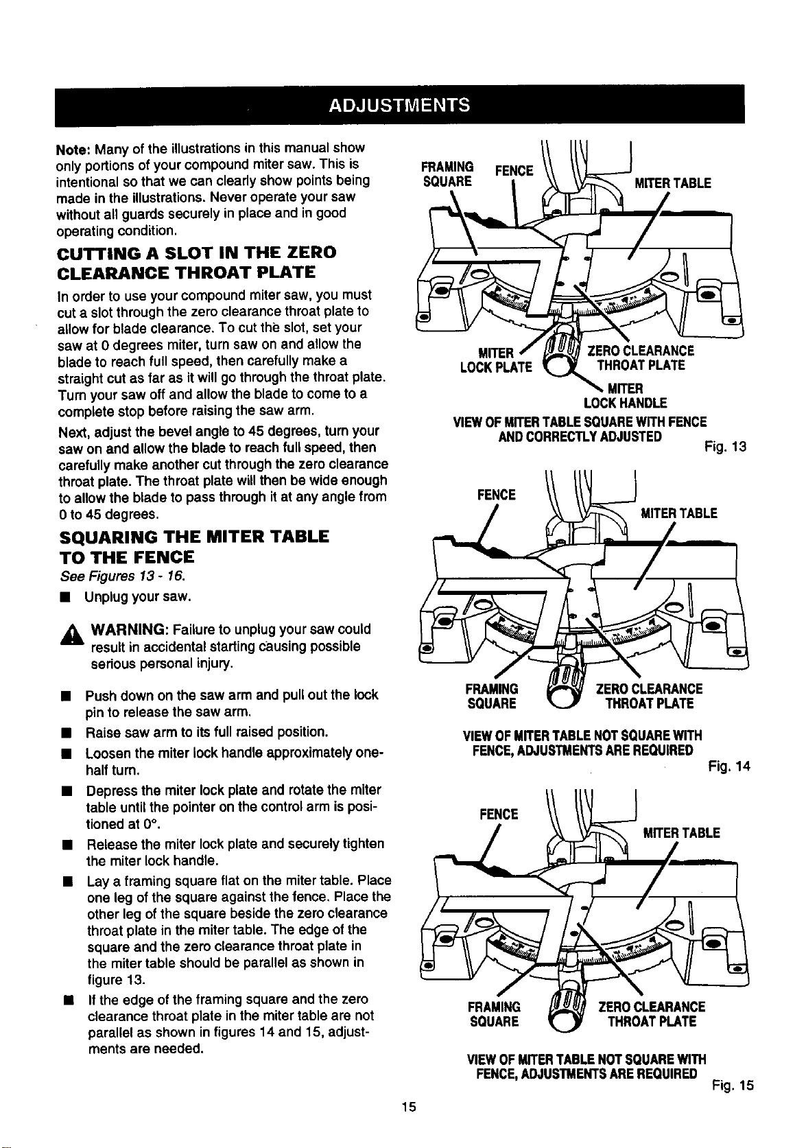
• Lay a framing square flat on the miter table. Place
one leg of the square against the fence. Place the
other leg of the square beside the zero clearance
throat plate in the miter table. The edge of the
square and the zero clearance throat plate in
the miter table should be parallel as shown in
figure 13.
• If the edge of the framing square and the zero
clearance throat plate in the miter table are not
parallel as shown in figures 14 and 15, adjust-
ments are needed.
F#A#AING FENCE // _--} MITERTABLE
LOCKPLATE _ THROATPLATE
MITER
LOCKHANDLE
VIEWOFMITERTABLESQUAREWITHFENCE
ANDCORRECTLYADJUSTED
Fig. 13
FENCE
MITERTABLE
FRAMING ZEROCLEARANCE
SQUARE THROM PLATE
VIEWOFMITERTABLENOTSQUAREWITH
FENCE,ADJUSTMENTSAREREQUIRED
Fig. 14
FENCE
MITERTABLE
FRAMING ZEROCLEARANCE
SQUARE THROATPLATE
VIEWOFMITERTABLENOTSQUAREWITH
FENCE,ADJUSTMENTSAREREQUIRED
Fig. 15
15
Loading ...
Loading ...
Loading ...