Loading ...
Loading ...
Loading ...
10 JL Audio
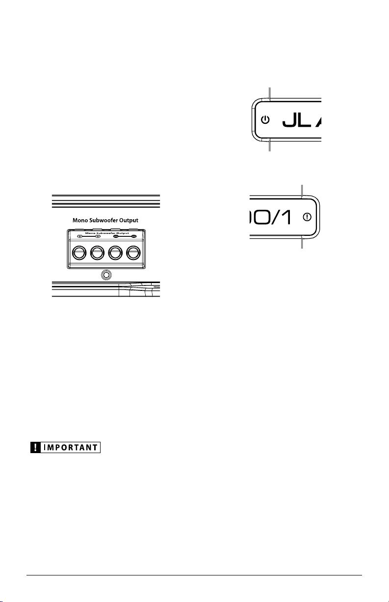
SUBWOOFER OUTPUTS
JD monoblock amplifiers are designed to
deliver power into subwoofer loads equal to or
greater than 2 ohms of nominal impedance.
The subwoofer outputs are designed to accept
16 AWG - 8 AWG wire. To connect the subwoofer
wires to the amplifier, first back out the set
screws on the top of the terminal block, using
the supplied 2.5 mm hex wrench. Strip 1/2 inch
(12 mm) of insulation from the end of each wire
and insert the bare wire into the terminal block,
seating it firmly so that no bare wire is exposed.
While holding the wire in place, tighten the set
screw firmly, taking care not to strip the head of
the screw.
You will notice that there are two “+” positive
connections and two “–” negative connections.
This is to facilitate multiple subwoofer wiring.
The two positive and two negative
connections are connected in parallel inside
the amplifier. They are not stereo outputs.
Connecting two subwoofers, each to one set of
positive and negative terminals, will result in
a parallel subwoofer connection. When only
connecting one pair of subwoofer wires, it is not
necessary to use both sets of connections.
Subwoofer loads below 2 ohms nominal are not
recommended and may cause the amplifier
to enter a protection mode.
STATUS LEDS / PROTECTION CIRCUITRY
JD amplifiers are equipped with separate
Status and Protection LEDs on the top surface
of the amplifier to indicate the amplifier’s
operating condition.
290 mm
11.40 in
262 mm
10.30 in
190 mm
7.50 in
53 mm
2.10 in
150 mm
5.90 in
Status LED
Constant Blue: The amplifier is on.
290 mm
11.40 in
262 mm
10.30 in
190 mm
7.50 in
53 mm
2.10 in
150 mm
5.90 in
Protection LED
1) Constant Red: Lights to indicate that the
amplifier has exceeded its safe operating
temperature, putting the amplifier into
a self-protection mode, which mutes the
power output of the amplifier. When its
temperature returns to a safe level, this LED
will turn off and the amplifier will return to
normal operating mode.
2) Flashing/Constant Red: The Protection
LED also illuminates during over-current
conditions. This may result in the LED
flashing as it corresponds to peaks in
music volume. Extended over-current
conditions will cause the LED to illuminate
continuously. During these events, the
amplifier’s output will be muted. Because
the muting behavior may be very short in
duration, it may manifest itself as an audible,
repetitive ticking or thumping noise in the
output. Over-current conditions can be
caused by a speaker impedance lower than
the optimum load impedance range for the
amplifier or a short-circuit in the speaker
wiring. The latter can result from a short
circuit between the positive and negative
speaker wires or between either speaker
wire and the vehicle chassis.
Loading ...
Loading ...
Loading ...