
Loading ...
Loading ...
Loading ...
INSTALLATION
connection so that it does not damage the hose. Check
for any foreign items in the drain hose and remove them.
• When arranging the drain hose, make sure the drain
hose is not cut, torn, or broken by any sharp edges on
the floor, the product itself, or the cabinet. A damaged
drain hose causes a leak.
ADJUSTING THE MOVABLE TOE KICK (DEPENDING
ON MODEL)
Now that you have successfully installed the dishwasher,
you need to attach the toe kick to the dishwasher. The two-
piece toe kick can be adjusted to the height and depth
needed for your kitchen.
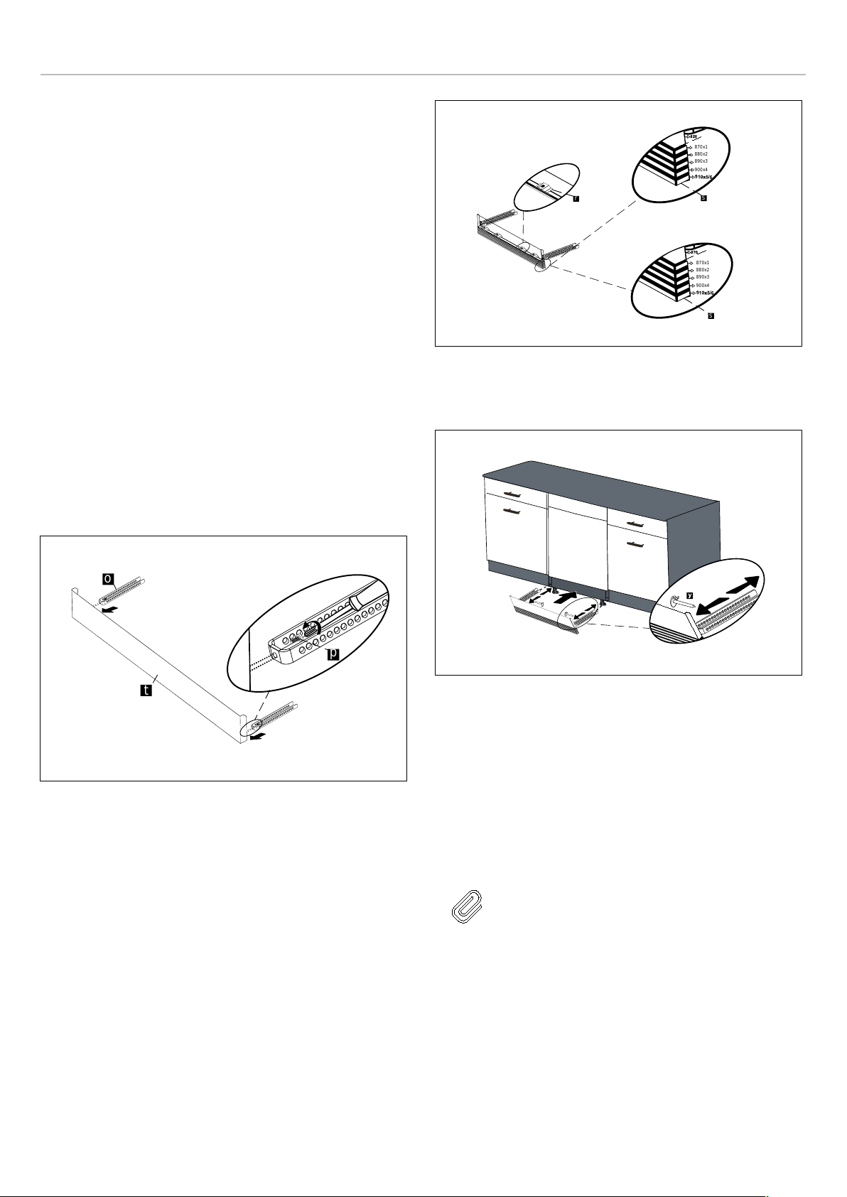
1)
• A. If the height is 32 7/16″ to 34 7/16″ (824mm-
874mm) and using short supports: adjustable plinth
metal 3 1/8" (80 mm) in length (v), toe kick brackets
(o) are installed. Mounting is done using Screws 5/32″
x 7/32″ (4mm x 6mm) with a Phillips Screwdriver.
• B. If the height is over 34 7/16″ (874mm) and using
short supports: adjustable plinth metal 5 1/8″
(130mm) in length (v), toe kick brackets (o) are
installed. Mounting is done using Screws 5/32″ x 7/
32″ (4mm x 6mm) with a Phillips Screwdriver.
Fig. 21
2) The adjustable plinth number is determined according to
the required distance and assembled to each other.
3) As shown in Fig. 22 , the cylindrical feet of the adjustable
plinth are attached to the plinth fixing metal parts and
inserted through the cavity of the part.
Depending on the desired depth, plinth locking (y) is
attached to the toe kick bracket (o).
Fig. 22
4) Finally, toe kick brackets (o) are attached to the gaps
under the machine and the installation is completed.
Fig. 23
INSTALLING THE OUTER DOOR (DEPENDING ON
MODEL)
As shown in Fig. 24 , you must measure the height and
depth of the cabinetry to determine the dimensions of the
outer door.
1) The installation plan is in the plastic bag secured to the
inside of the Dishwasher door.
NOTE
While securing the installation plan, make
sure that the plan adheres to the inside of
the door. When fastening is complete, the
installation plan must remain straight on the
outer door.
2) As shown in Fig. 24 , the screw hole is opened to the
outer door from the points marked on the installation
plan. Diameter of Drill Bit: 5/64″ (2 mm) Depth of Drill Bit:
15/32″ (12 mm)
o
p
t
r
s
870x1
880x2
890x3
900x4
s
870x1
880x2
890x3
900x4
14
r
s
870x1
880x2
890x3
900x4
s
870x1
880x2
890x3
900x4
14
r
s
870x1
880x2
890x3
900x4
s
870x1
880x2
890x3
900x4
14
19
Loading ...
Loading ...
Loading ...