Patent Pending
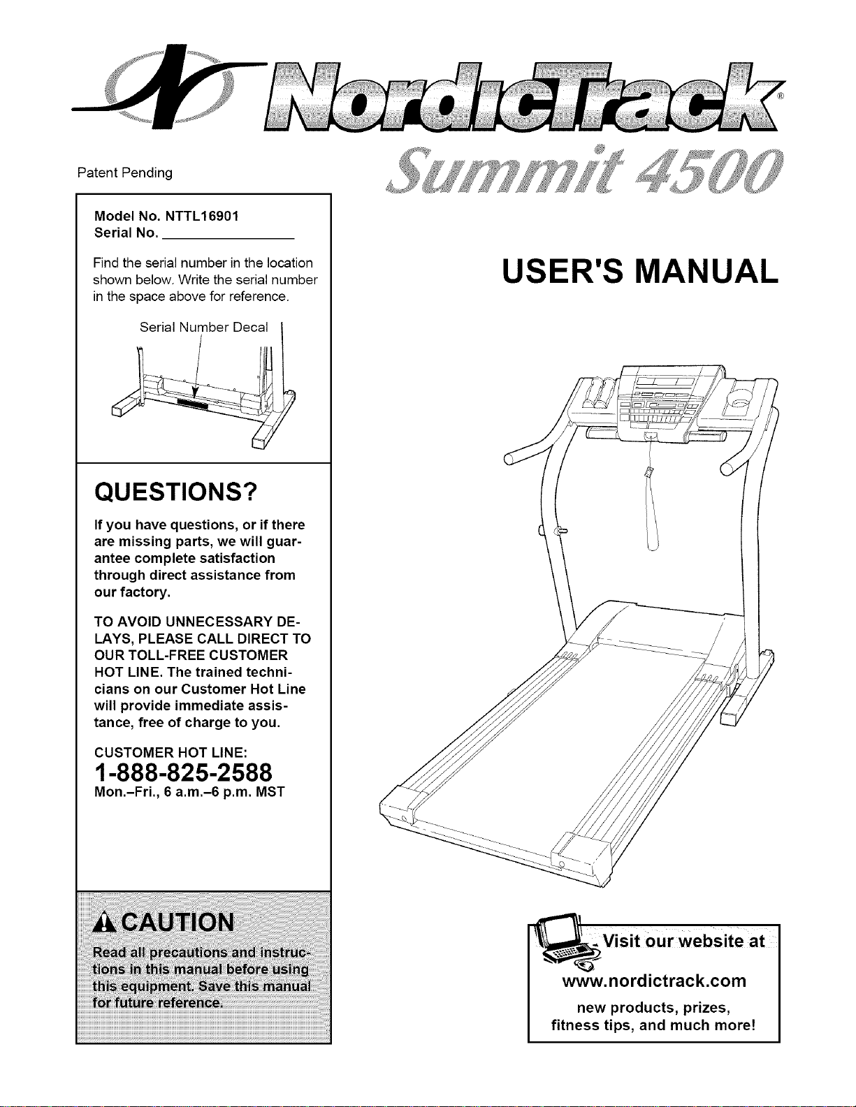
Model No. NTTL16901
Serial No.
Find the serial number in the location
shown below. Write the serial number
in the space above for reference.
Serial Number Decal
QUESTIONS?
If you have questions, or if there
are missing parts, we will guar-
antee complete satisfaction
through direct assistance from
our factory.
TO AVOID UNNECESSARY DE-
LAYS, PLEASE CALL DIRECT TO
OUR TOLL-FREE CUSTOMER
HOT LINE. The trained techni-
cians on our Customer Hot Line
will provide immediate assis-
tance, free of charge to you.
CUSTOMER HOT LINE:
1-888-825-2588
Mon.-Fri., 6 a.m.-6 p.m. MST
USER'S MANUAL
]Visit our website at
www, nordictrack.com
new products, prizes,
fitness tips, and much more!

@
TABLE OF CONTENTS
IMPORTANT PRECAUTIONS ................................................................. 3
BEFORE YOU BEGIN ....................................................................... 5
ASSEMBLY ............................................................................... 6
OPERATION AND ADJUSTMENT ............................................................. 8
HOW TO FOLD AND MOVE THE TREADMILL .................................................. 25
TROUBLE-SHOOTING ..................................................................... 26
CONDITIONING GUIDELINES ............................................................... 28
PART LIST ............................................................................... 30
ORDERING REPLACEMENT PARTS .......................................................... 31
LIMITED WARRANTY ............................................................... Back Cover
Note: An EXPLODED DRAWING is attached in the center of this manual.
NordicTrack is a registered trademark of ICON Health & Fitness, Inc.
2

IMPORTANT PRECAUTIONS
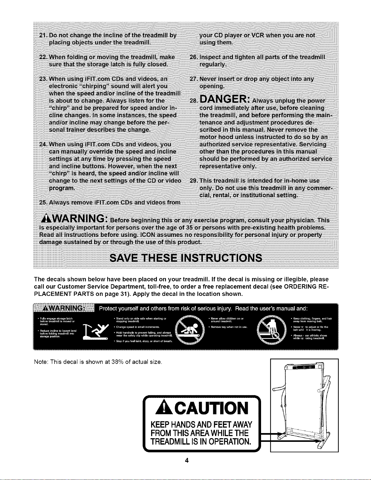
The decals shown below have been placed on your treadmill. If the decal is missing or illegible, please
call our Customer Service Department, toll-free, to order a free replacement decal (see ORDERING RE-
PLACEMENT PARTS on page 31). Apply the decal in the location shown.
Note: This decal is shown at 38% of actual size.
[.°.o+.o.i
KEEPHANDSANDFEETAWAY
FROMTHISAREAWHILETHE
TREADMILLIS INOPERATION.
BEFORE YOU BEGIN
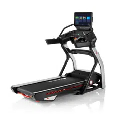
Thank you for selecting the revolutionary NordicTrack ®
SUMMIT 4500 treadmill. The SUMMIT 4500 treadmill
combines advanced technology with innovative design
to help you get the most from your exercise program in
the convenience of your home. And when you're not
exercising, the unique SUMMIT 4500 can be folded up,
requiring less than half the floor space of other tread-
mills.
For your benefit, read this manual carefully before
using the treadmill. If you have additional questions,
please call our Customer Service Department toll-free
at 1-888-825-2588, Monday through Friday, 6 a.m.
until 6 p.m. Mountain Time (excluding holidays). To
help us assist you, please note the product model
number and serial number before calling. The model
number of the treadmill is NTTL16901. The serial num-
ber can be found on a decal attached to the treadmill
(see the front cover of this manual for the location).
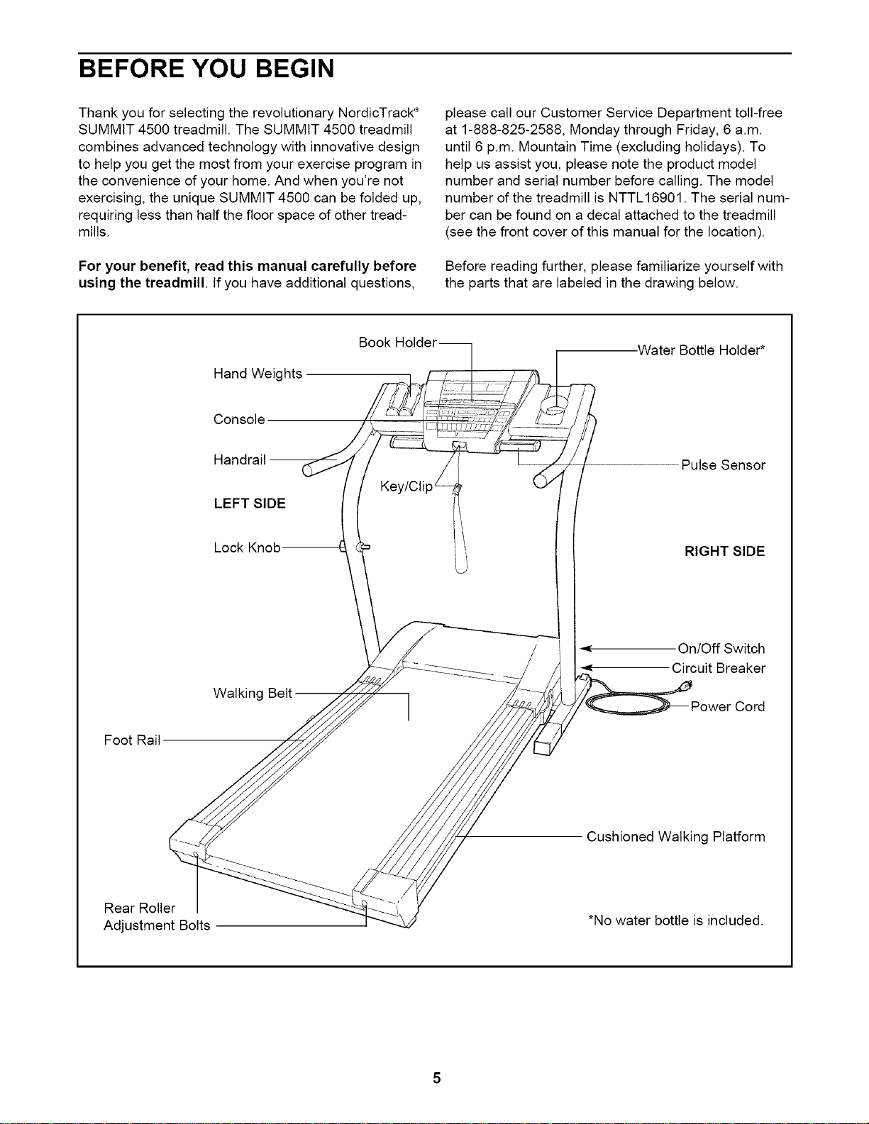
Before reading further, please familiarize yourself with
the parts that are labeled in the drawing below.
Foot Rail
Hand Weights
Console
Handrail --
LEFT SIDE
Lock Knob
Walking
Book
1
Water Bottle Holder*
Pulse Sensor
RIGHT SIDE
On/Off Switch
Circuit Breaker
Cushioned Walking Platform
Rear Roller
Adjustment Bolts
*No water bottle is included.
ASSEMBLY
Assembly requires two people. Set the treadmill in a cleared area and remove all packing materials. Do not
dispose of the packing materials until assembly is completed. Assembly requires the included allen wrench i
and your own phillips screwdriver _ and wire cutters _j>.
Note: The underside of the treadmill walking belt is coated with high-performance lubricant. During shipping, a
small amount of lubricant may be transferred to the top of the walking belt or the shipping carton. This is a normal
condition and does not affect treadmill performance. If there is lubricant on top of the walking belt, simply wipe off
the lubricant with a soft cloth and a mild, non-abrasive cleaner.
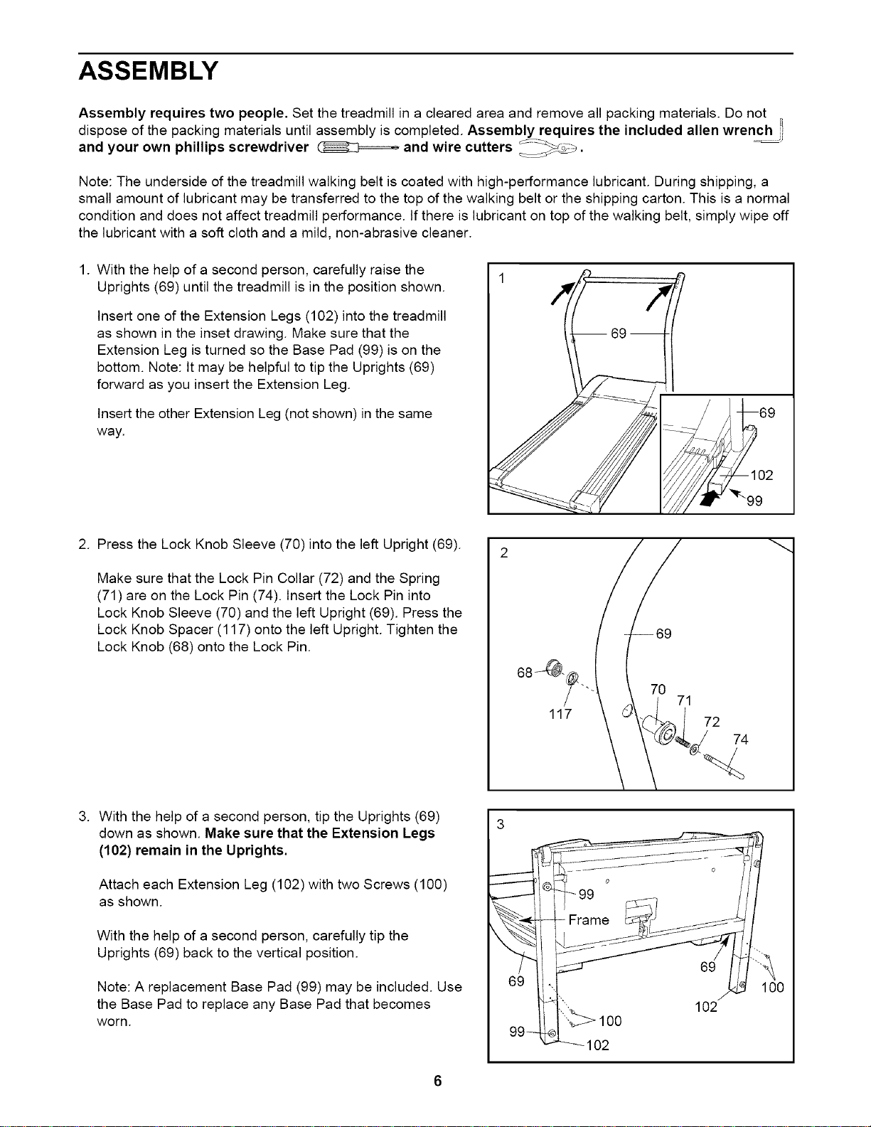
1. With the help of a second person, carefully raise the
Uprights (69) until the treadmill is in the position shown.
Insert one of the Extension Legs (102) into the treadmill
as shown in the inset drawing. Make sure that the
Extension Leg is turned so the Base Pad (99) is on the
bottom. Note: It may be helpful to tip the Uprights (69)
forward as you insert the Extension Leg.
Insert the other Extension Leg (not shown) in the same
way.
69
2. Press the Lock Knob Sleeve (70) into the left Upright (69).
Make sure that the Lock Pin Collar (72) and the Spring
(71) are on the Lock Pin (74). Insert the Lock Pin into
Lock Knob Sleeve (70) and the left Upright (69). Press the
Lock Knob Spacer (117) onto the left Upright. Tighten the
Lock Knob (68) onto the Lock Pin.
72
74
3. With the help of a second person, tip the Uprights (69)
down as shown. Make sure that the Extension Legs
(102) remain in the Uprights.
Attach each Extension Leg (102) with two Screws (100)
as shown.
With the help of a second person, carefully tip the
Uprights (69) back to the vertical position.
Note: A replacement Base Pad (99) may be included. Use
the Base Pad to replace any Base Pad that becomes
worn. 00
102
102
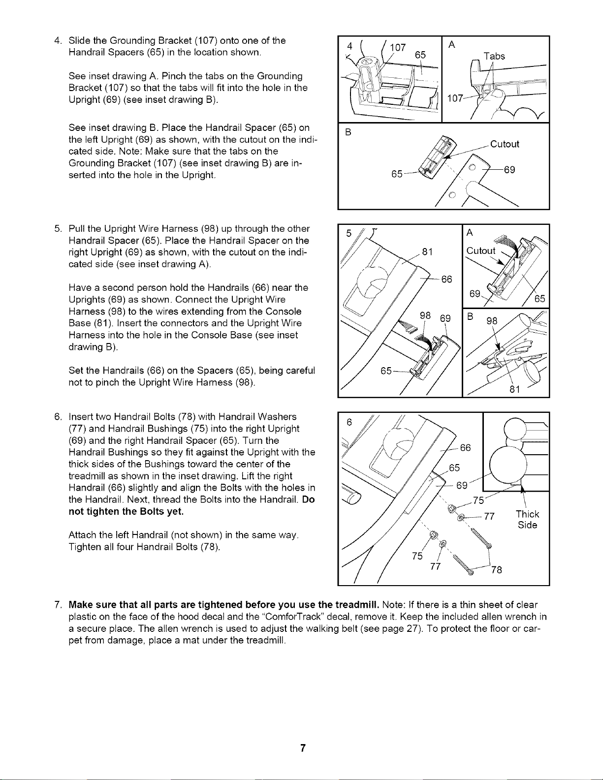
4. SlidetheGroundingBracket(107)ontooneofthe
HandrailSpacers(65)inthelocationshown.
SeeinsetdrawingA.PinchthetabsontheGrounding
Bracket(107)sothatthetabswillfitintotheholeinthe
Upright(69)(seeinsetdrawingB).
SeeinsetdrawingB.PlacetheHandrailSpacer(65)on
theleftUpright(69)asshown,withthecutoutontheindi-
catedside.Note:Makesurethatthetabsonthe
GroundingBracket(107)(seeinsetdrawingB)arein-
sertedintotheholeintheUpright.
z
A
Tabs
5. Pull the Upright Wire Harness (98) up through the other
Handrail Spacer (65). Place the Handrail Spacer on the
right Upright (69) as shown, with the cutout on the indi-
cated side (see inset drawing A).
Have a second person hold the Handrails (66) near the
Uprights (69) as shown. Connect the Upright Wire
Harness (98) to the wires extending from the Console
Base (81). Insert the connectors and the Upright Wire
Harness into the hole in the Console Base (see inset
drawing B).
Set the Handrails (66) on the Spacers (65), being careful
not to pinch the Upright Wire Harness (98).
81
A
Cutout_
6. Insert two Handrail Bolts (78) with Handrail Washers
(77) and Handrail Bushings (75) into the right Upright
(69) and the right Handrail Spacer (65). Turn the
Handrail Bushings so they fit against the Upright with the
thick sides of the Bushings toward the center of the
treadmill as shown in the inset drawing. Lift the right
Handrail (66) slightly and align the Bolts with the holes in
the Handrail. Next, thread the Bolts into the Handrail. Do
not tighten the Bolts yet.
Attach the left Handrail (not shown) in the same way.
Tighten all four Handrail Bolts (78).
75
77 78
Thick
Side
7. Make sure that all parts are tightened before you use the treadmill. Note: tf there is a thin sheet of clear
plastic on the face of the hood decal and the "ComforTrack" decal, remove it. Keep the included allen wrench in
a secure place. The allen wrench is used to adjust the walking belt (see page 27). To protect the floor or car-
pet from damage, place a mat under the treadmill.
OPERATION AND ADJUSTMENT
THE PERFORMANT LUBETM WALKING BELT
Your treadmill features a walking belt coated with
PERFORMANT LUBE TM, a high-performance lubricant.
IMPORTANT: Never apply silicone spray or other
substances to the walking belt or the walking plat-
form. Such substances will deteriorate the walking
belt and cause excessive wear.
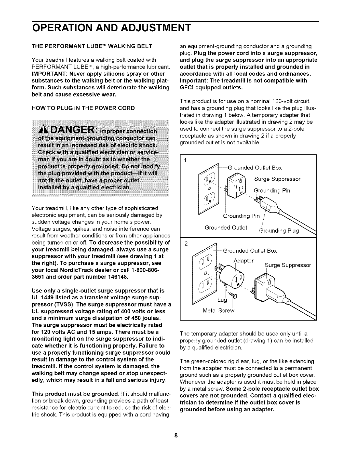
HOW TO PLUG IN THE POWER CORD
an equipment-grounding conductor and a grounding
plug. Plug the power cord into a surge suppressor,
and plug the surge suppressor into an appropriate
outlet that is properly installed and grounded in
accordance with all local codes and ordinances.
Important: The treadmill is not compatible with
GFCl-equipped outlets.
This product is for use on a nominal 120-volt circuit,
and has a grounding plug that looks like the plug illus-
trated in drawing 1 below. A temporary adapter that
looks like the adapter illustrated in drawing 2 may be
used to connect the surge suppressor to a 2-pole
receptacle as shown in drawing 2 if a properly
grounded outlet is not available.
Your treadmill, like any other type of sophisticated
electronic equipment, can be seriously damaged by
sudden voltage changes in your home's power.
Voltage surges, spikes, and noise interference can
result from weather conditions or from other appliances
being turned on or off. To decrease the possibility of
your treadmill being damaged, always use a surge
suppressor with your treadmill (see drawing 1 at
the right). To purchase a surge suppressor, see
your local NordicTrack dealer or call 1-800-806-
3651 and order part number 146148.
Use only a single-outlet surge suppressor that is
UL 1449 listed as a transient voltage surge sup-
pressor (TVSS). The surge suppressor must have a
UL suppressed voltage rating of 400 volts or less
and a minimum surge dissipation of 450 joules.
The surge suppressor must be electrically rated
for 120 volts AC and 15 amps. There must be a
monitoring light on the surge suppressor to indi-
cate whether it is functioning properly. Failure to
use a properly functioning surge suppressor could
result in damage to the control system of the
treadmill. If the control system is damaged, the
walking belt may change speed or stop unexpect-
edly, which may result in a fall and serious injury.
This product must be grounded. If it should malfunc-
tion or break down, grounding provides a path of least
resistance for electric current to reduce the risk of elec-
tric shock. This product is equipped with a cord having
Outlet Box
Suppressor
Grounding Pin
Grounding Pin
Grounded Outlet
Grounding Plug
Metal Screw
Outlet Box
Adapter
The temporary adapter should be used only until a
properly grounded outlet (drawing 1) can be installed
by a qualified electrician.
The green-colored rigid ear, lug, or the like extending
from the adapter must be connected to a permanent
ground such as a properly grounded outlet box cover.
Whenever the adapter is used it must be held in place
by a metal screw. Some 2-pole receptacle outlet box
covers are not grounded. Contact a qualified elec-
trician to determine if the outlet box cover is
grounded before using an adapter.
o
o
o
o
o
o
o
o
o
TRAINING ZONES
I o
.............. I;C; ...........................................................................
INCLINE EZ SEGM _\TTIME _ DISTANC EZ HART RAT _ SPEED
o
Is-;_;,,,L,so /
o
o
o
o
o
PROGRAM CONTROL
o
o
o
o
o
o
o
Pulse
Sensor
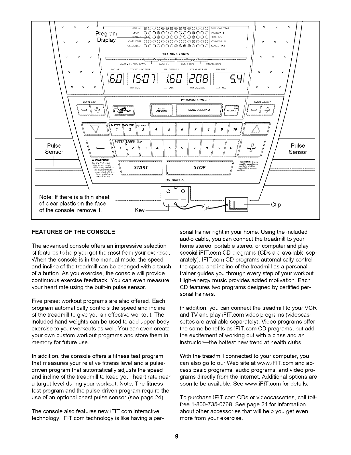
Note: If there is a thin sheet
of clear plastic on the face
of the console, remove it.
START
o o
Key
Pulse
Sensor
Clip
FEATURES OF THE CONSOLE
The advanced console offers an impressive selection
of features to help you get the most from your exercise.
When the console is in the manual mode, the speed
and incline of the treadmill can be changed with a touch
of a button. As you exercise, the console will provide
continuous exercise feedback. You can even measure
your heart rate using the built-in pulse sensor.
Five preset workout programs are also offered. Each
program automatically controls the speed and incline
of the treadmill to give you an effective workout. The
included hand weights can be used to add upper-body
exercise to your workouts as well. You can even create
your own custom workout programs and store them in
memory for future use.
In addition, the console offers a fitness test program
that measures your relative fitness level and a pulse-
driven program that automatically adjusts the speed
and incline of the treadmill to keep your heart rate near
a target level during your workout. Note: The fitness
test program and the pulse-driven program require the
use of an optional chest pulse sensor (see page 24).
The console also features new iFIT.com interactive
technology. IFIT.com technology is like having a per-
sonal trainer right in your home. Using the included
audio cable, you can connect the treadmill to your
home stereo, portable stereo, or computer and play
special iFtT.com CD programs (CDs are available sep-
arately). IFIT.com CD programs automatically control
the speed and incline of the treadmill as a personal
trainer guides you through every step of your workout.
High-energy music provides added motivation. Each
CD features two programs designed by certified per-
sonal trainers.
In addition, you can connect the treadmill to your VCR
and TV and play iFIT.com video programs (videocas-
settes are available separately). Video programs offer
the same benefits as iFIT.com CD programs, but add
the excitement of working out with a class and an
instructor--the hottest new trend at health clubs.
With the treadmill connected to your computer, you
can also go to our Web site at www.iFIT.com and ac-
cess basic programs, audio programs, and video pro-
grams directly from the internet. Additional options are
soon to be available. See www.iFIT.com for details.
To purchase iFIT.com CDs or videocassettes, call toll-
free 1-800-735-0768. See page 24 for information
about other accessories that will help you get even
more from your exercise.
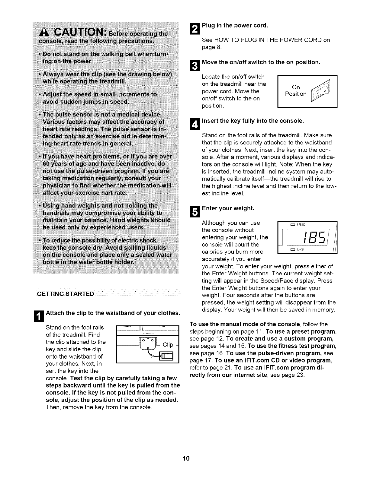
GETTING STARTED
B
Attach the clip to the waistband of your clothes.
Stand on the foot rails
of the treadmill. Find
the clip attached to the
key and slide the clip
onto the waistband of
your clothes. Next, in-
sert the key into the
.......L:::':L___J)k--_: .................
console. Test the clip by carefully taking a few
steps backward until the key is pulled from the
console. If the key is not pulled from the con-
sole, adjust the position of the clip as needed.
Then, remove the key from the console.
B Plug in the power cord.
See HOW TO PLUG IN THE POWER CORD on
page 8.
kl
Move the on/off switch to the on position.
Locate the on/off switch
on the treadmill near the
power cord. Move the
on/off switch to the on
position.
Position
B
Insert the key fully into the console.
Stand on the foot rails of the treadmill. Make sure
that the clip is securely attached to the waistband
of your clothes. Next, insert the key into the con-
sole. After a moment, various displays and indica-
tors on the console will light. Note: When the key
is inserted, the treadmill incline system may auto-
matically calibrate itself--the treadmill will rise to
the highest incline level and then return to the low-
est incline level.
_ Enter your weight.
Although you can use
the console without
entering your weight, the
console will count the
calories you burn more
accurately if you enter
your weight. To enter your weight, press either of
the Enter Weight buttons. The current weight set-
ting will appear in the Speed/Pace display. Press
the Enter Weight buttons again to enter your
weight. Four seconds after the buttons are
pressed, the weight setting will disappear from the
display. Your weight will then be saved in memory.
To use the manual mode of the console, follow the
steps beginning on page 11. To use a preset program,
see page 12. To create and use a custom program,
see pages 14 and 15. To use the fitness test program,
see page 16. To use the pulse-driven program, see
page 17. To use an iFIT.com CD or video program,
refer to page 21. To use an iFIT.com program di-
rectly from our internet site, see page 23.
10
HOW TO USE THE MANUAL MODE
_1 Insert the key fully into the console.
See GETTING STARTED on page 10.
FI
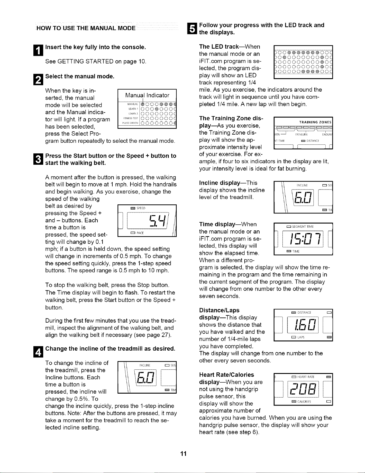
Select the manual mode.
When the key is in-
serted, the manual
mode will be selected
and the Manual indica-
tor will light. If a program
has been selected,
press the Select Pro-
Manual Indicator
M^kUA_$000@@@_
L,_R__ 000@000(
A_2 O000000C
_ _ _ O000000C
gram button repeatedly to select the manual mode.
1_1 Press the Start button or the Speed + button to
start the walking belt.
A moment after the button is pressed, the walking
belt will begin to move at 1 mph. Hold the handrails
and begin walking. As you exercise, change the
speed of the walking
belt as desired by / [ = S,EEO
pressing the Speed +
and - buttons. Each
time a button is
pressed, the speed set- = _"<_
ting will change by 0.1
mph; if a button is held down, the speed setting
will change in increments of 0.5 mph. To change
the speed setting quickly, press the 1-step speed
buttons. The speed range is 0.5 mph to 10 mph.
To stop the walking belt, press the Stop button.
The Time display will begin to flash. To restart the
walking belt, press the Start button or the Speed +
button.
During the first few minutes that you use the tread-
mill, inspect the alignment of the walking belt, and
align the walking belt if necessary (see page 27).
B
Change the incline of the treadmill as desired.
To change the incline of
the treadmill, press the
Incline buttons. Each
time a button is
pressed, the incline will
change by 0.5%. To
/ INCLINE _ SEG
change the incline quickly, press the 1-step incline
buttons. Note: After the buttons are pressed, it may
take a moment for the treadmill to reach the se-
lected incline setting.
_ ollow your progress with the LED track and
the displays.
The LED track--When
the manual mode or an
iFIT.com program is se-
lected, the program dis-
play will show an LED
track representing 1/4
)O0@@@@@@@OO
)0@0000000@0
)000000000@0
)000000000@0
)00000@@@@00
mile. As you exercise, the indicators around the
track will light in sequence until you have com-
pleted 1/4 mile. A new lap will then begin.
The Training Zone dis-
play--As you exercise,
the Training Zone dis-
play will show the ap-
proximate intensity level
of your exercise. For ex-
ample, if four to six indicators in the display are lit,
your intensity level is ideal for fat burning.
Incline display--This
display shows the incline
level of the treadmill.
Time display--When
the manual mode or an
iFIT.com program is se-
lected, this display will
show the elapsed time.
When a different pro-
l _ SEGMENT TIME 1
I I- .I-I
I -_1"1_17
TIME
gram is selected, the display will show the time re-
maining in the program and the time remaining in
the current segment of the program. The display
will change from one number to the other every
seven seconds.
Distance/Laps
display--This display
shows the distance that
you have walked and the
number of 1/4-mile laps
you have completed.
The display will change from one number to the
other every seven seconds.
Heart Rate/Calories
display--When you are
not using the handgrip
pulse sensor, this
display will show the
approximate number of
calories you have burned. When you are using the
handgrip pulse sensor, the display will show your
heart rate (see step 6).
11
Speed/Pace display--
This display shows the
speed of the walking
belt and your current
pace (pace is mea-
sured in minutes per
mile). Every seven seconds, the display will
change from one number to the other.
Note: The console can
display speed and dis-
tance in either miles or
kilometers. To find
which unit of measure-
ment is selected, hold
down the Stop button while inserting the key into
the console. An "E," for English miles, or an "M,"
for metric kilometers, will appear in the Speed/
Pace display. Press the Speed + button to change
the unit of measurement. When the desired unit of
measurement is selected, remove the key and
then reinsert it. Note: For simplicity, all instructions
in this manual refer to miles.
To reset the displays, press the Stop button, re-
move the key, and then reinsert the key.
D
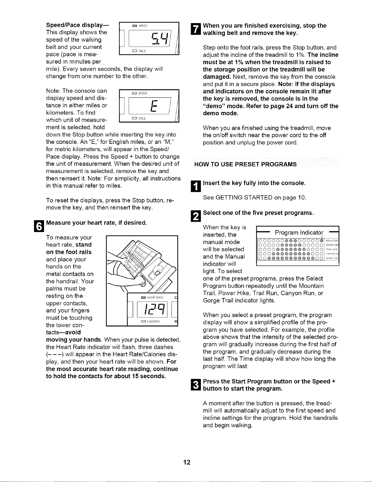
Measure your heart rate, if desired.
To measure your
heart rate, stand
on the foot rails
and place your
hands on the
metal contacts on
the handrail. Your
palms must be
resting on the
upper contacts,
and your fingers
must be touching _=c_,Lo_,_s
the lower con-
tacts--avoid
moving your hands. When your pulse is detected,
the Heart Rate indicator will flash, three dashes
(- - -) will appear in the Heart Rate/Calories dis-
play, and then your heart rate will be shown. For
the most accurate heart rate reading, continue
to hold the contacts for about 15 seconds.
B hen you are finished exercising, stop the
walking belt and remove the key.
Step onto the foot rails, press the Stop button, and
adjust the incline of the treadmill to 1%. The incline
must be at 1% when the treadmill is raised to
the storage position or the treadmill will be
damaged. Next, remove the key from the console
and put it in a secure place. Note: If the displays
and indicators on the console remain lit after
the key is removed, the console is in the
"demo" mode. Refer to page 24 and turn off the
demo mode.
When you are finished using the treadmill, move
the on/off switch near the power cord to the off
position and unplug the power cord.
HOW TO USE PRESET PROGRAMS
_1 Insert the key fully into the console.
See GETTING STARTED on page 10.
F,I
Select one of the five preset programs.
When the key is
inserted, the
manual mode
will be selected
and the Manual
indicator will
light. To select
Program Indicator m
O00OO0@@@O0000(_ _o_r,,_.
O00OO@@@@@O0000 Po_,_ _K
O00O@@@@@@@O000 _A_,_u,_
QQO@@@@@@@@@OQO cAr,,_u,__
00@@@@@@@@@@@00 _,o_<.u
one of the preset programs, press the Select
Program button repeatedly until the Mountain
Trail, Power Hike, Trail Run, Canyon Run, or
Gorge Trail indicator lights.
When you select a preset program, the program
display will show a simplified profile of the pro-
gram you have selected. For example, the profile
above shows that the intensity of the selected pro-
gram will gradually increase during the first half of
the program, and gradually decrease during the
last half. The Time display will show how long the
program will last.
_1 Press the Start Program button or the Speed +
button to start the program.
A moment after the button is pressed, the tread-
mill will automatically adjust to the first speed and
incline settings for the program. Hold the handrails
and begin walking.
12
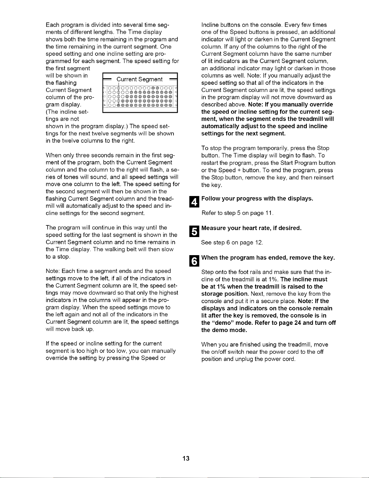
Each program is divided into several time seg-
ments of different lengths. The Time display
shows both the time remaining in the program and
the time remaining in the current segment. One
speed setting and one incline setting are pro-
grammed for each segment. The speed setting for
the first segment
will be shown in
the flashing
Current Segment
column of the pro-
gram display.
(The incline set-
tings are not
shown in the program display.) The speed set-
tings for the next twelve segments will be shown
in the twelve columns to the right.
When only three seconds remain in the first seg-
ment of the program, both the Current Segment
column and the column to the right will flash, a se-
ries of tones will sound, and all speed settings will
move one column to the left. The speed setting for
the second segment will then be shown in the
flashing Current Segment column and the tread-
mill will automatically adjust to the speed and in-
cline settings for the second segment.
The program will continue in this way until the
speed setting for the last segment is shown in the
Current Segment column and no time remains in
the Time display. The walking belt will then slow
to a stop.
Note: Each time a segment ends and the speed
settings move to the left, if all of the indicators in
the Current Segment column are lit, the speed set-
tings may move downward so that only the highest
indicators in the columns will appear in the pro-
gram display. When the speed settings move to
the left again and not all of the indicators in the
Current Segment column are lit, the speed settings
will move back up.
If the speed or incline setting for the current
segment is too high or too low, you can manually
override the setting by pressing the Speed or
Incline buttons on the console. Every few times
one of the Speed buttons is pressed, an additional
indicator will light or darken in the Current Segment
column. If any of the columns to the right of the
Current Segment column have the same number
of lit indicators as the Current Segment column,
an additional indicator may light or darken in those
columns as well. Note: If you manually adjust the
speed setting so that all of the indicators in the
Current Segment column are lit, the speed settings
in the program display will not move downward as
described above. Note: If you manually override
the speed or incline setting for the current seg-
ment, when the segment ends the treadmill will
automatically adjust to the speed and incline
settings for the next segment.
B
To stop the program temporarily, press the Stop
button. The Time display will begin to flash. To
restart the program, press the Start Program button
or the Speed + button. To end the program, press
the Stop button, remove the key, and then reinsert
the key.
Follow your progress with the displays.
Refer to step 5 on page 11.
_ easure your heart rate, if desired.
See step 6 on page 12.
r_When the program has ended, remove the key.
Step onto the foot rails and make sure that the in-
cline of the treadmill is at 1%. The incline must
be at 1% when the treadmill is raised to the
storage position. Next, remove the key from the
console and put it in a secure place. Note: If the
displays and indicators on the console remain
lit after the key is removed, the console is in
the "demo" mode. Refer to page 24 and turn off
the demo mode.
When you are finished using the treadmill, move
the on/off switch near the power cord to the off
position and unplug the power cord.
13
HOWTO CREATE CUSTOM PROGRAMS
_1 Insert the key fully into the console.
See GETTING STARTED on page 10.
B
Select one of the custom programs.
When the key is in-
serted, the manual
mode will be selected
and the Manual indica-
tor will light. To select
one of the custom pro-
grams, press the Select
Learn Indicator
oOoOOOoOoOoOoo
LE_*_2 000000000
FITBESS TE_ _ O0000OO00
P s-_,,. 00@@@@@@@
Program button repeatedly until the Learn 1 or
Learn 2 indicator lights.
_'1 Press the Start Program button or the Speed +
button to start the walking belt.
A moment after the button is pressed, the walking
belt will begin to move. Hold the handrails and
begin walking.
B ress the Record button and program the
desired speed and incline settings.
When the Record button is pressed, the indicator
on the button will light. Speed and incline settings
can be programmed only when the indicator is
lit. Note: When the indicator on the Record button
is lit, the Time display will show the elapsed time
instead of the time remaining in the program.
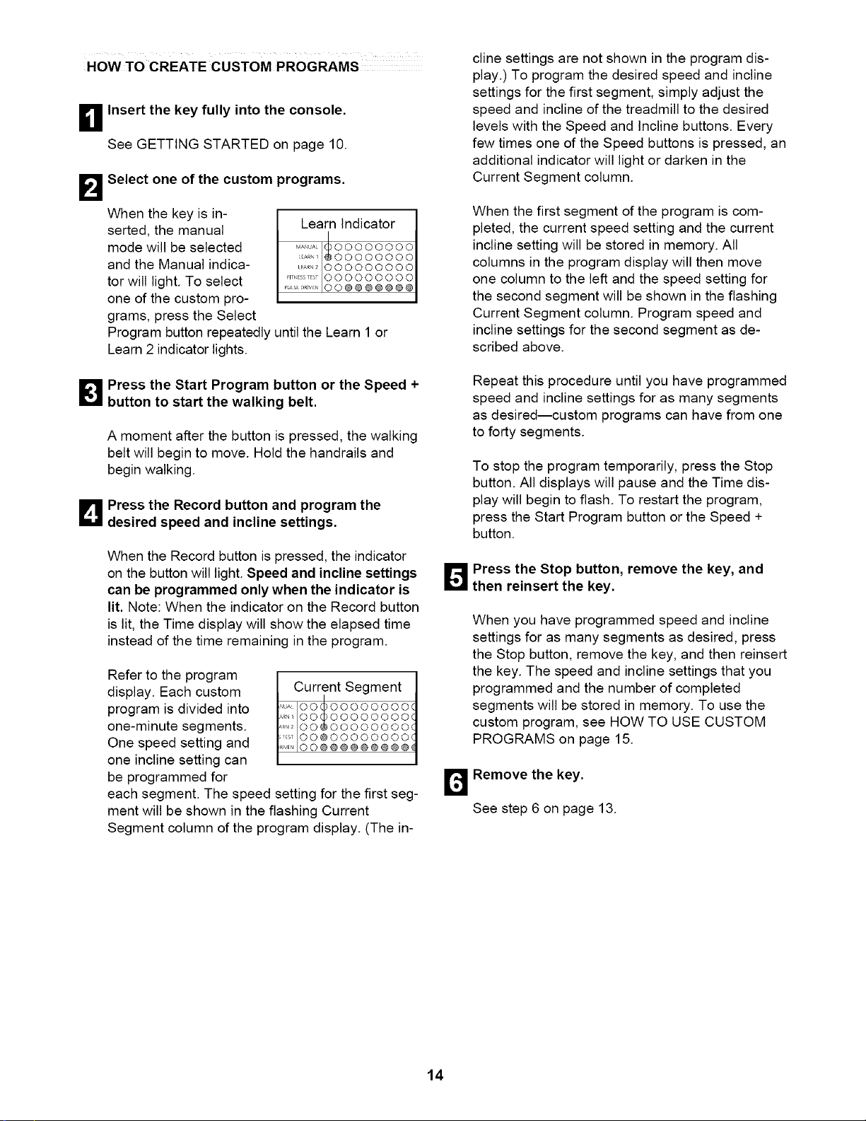
Refer to the program
display. Each custom
program is divided into
one-minute segments.
One speed setting and
one incline setting can
be programmed for
Current Segment
00500000000(
ooq) ooooo000(
OO@OOOOOOOO(
sT OO@OOOOOOOO(
_,vEOO@@@@@@@@@_
each segment. The speed setting for the first seg-
ment will be shown in the flashing Current
Segment column of the program display. (The in-
cline settings are not shown in the program dis-
play.) To program the desired speed and incline
settings for the first segment, simply adjust the
speed and incline of the treadmill to the desired
levels with the Speed and Incline buttons. Every
few times one of the Speed buttons is pressed, an
additional indicator will light or darken in the
Current Segment column.
When the first segment of the program is com-
pleted, the current speed setting and the current
incline setting will be stored in memory. All
columns in the program display will then move
one column to the left and the speed setting for
the second segment will be shown in the flashing
Current Segment column. Program speed and
incline settings for the second segment as de-
scribed above.
Repeat this procedure until you have programmed
speed and incline settings for as many segments
as desired--custom programs can have from one
to forty segments.
To stop the program temporarily, press the Stop
button. All displays will pause and the Time dis-
play will begin to flash. To restart the program,
press the Start Program button or the Speed +
button.
_ ress the Stop button, remove the key, and
then reinsert the key.
When you have programmed speed and incline
settings for as many segments as desired, press
the Stop button, remove the key, and then reinsert
the key. The speed and incline settings that you
programmed and the number of completed
segments will be stored in memory. To use the
custom program, see HOW TO USE CUSTOM
PROGRAMS on page 15.
r_ Remove the key.
See step 6 on page 13.
14
HOWTO USECUSTOM PROGRAMS
_! Insert the key fully into the console.
See GETTING STARTED on page 10.
B
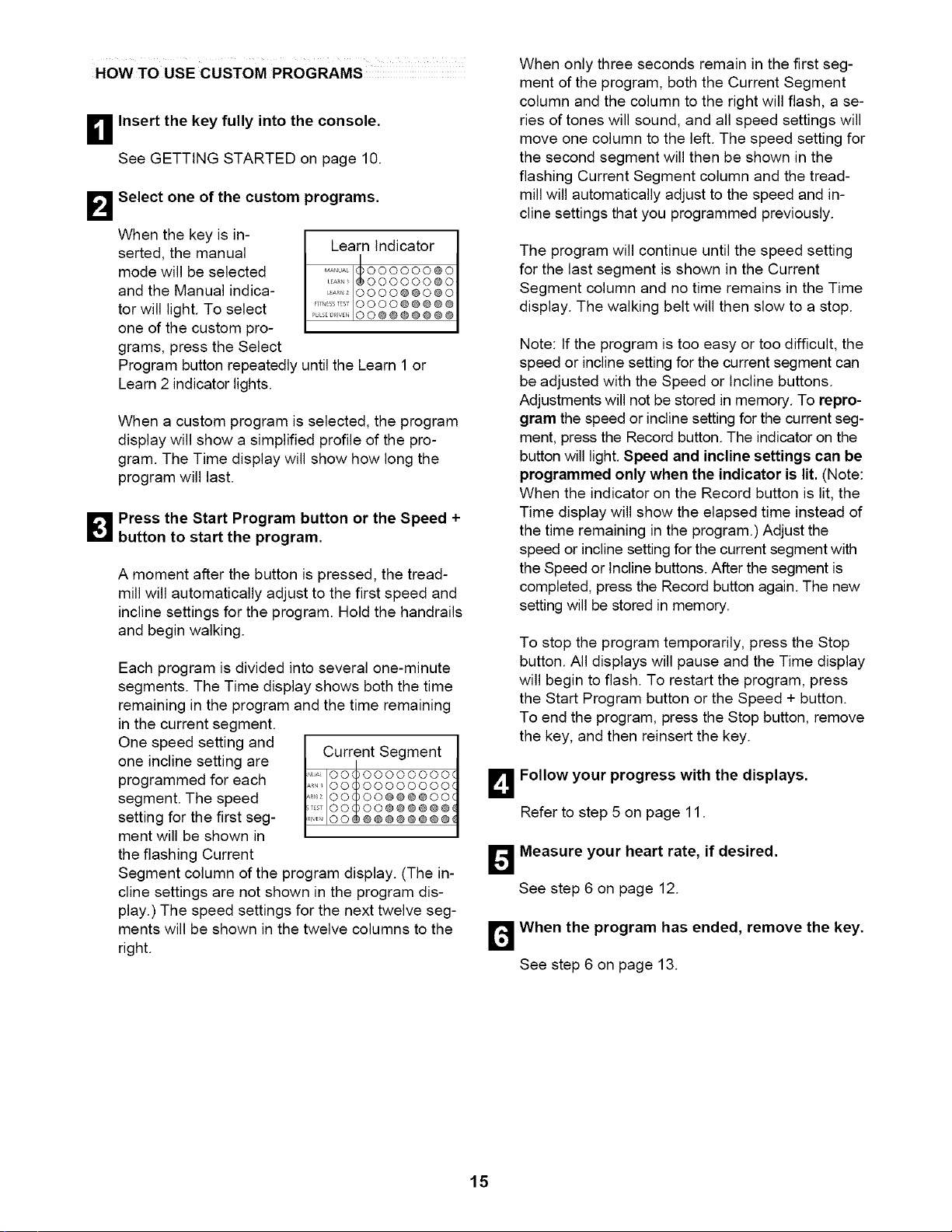
Select one of the custom programs.
When the key is in-
serted, the manual
mode will be selected
and the Manual indica-
tor will light. To select
one of the custom pro-
grams, press the Select
Learn Indicator
O00000@O
000000@0
J_2 O000@@O@O
_ ss s_ O00O@@@@@
ULSE RIVE_, 00@@0@@@@
Program button repeatedly until the Learn 1 or
Learn 2 indicator lights.
When a custom program is selected, the program
display will show a simplified profile of the pro-
gram. The Time display will show how long the
program will last.
_1 Press the Start Program button or the Speed +
button to start the program.
A moment after the button is pressed, the tread-
mill will automatically adjust to the first speed and
incline settings for the program. Hold the handrails
and begin walking.
Each program is divided into several one-minute
segments. The Time display shows both the time
remaining in the program and the time remaining
in the current segment.
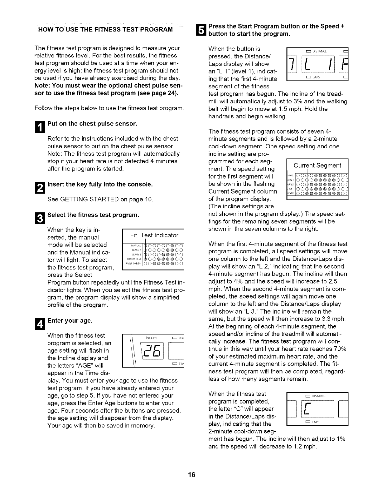
One speed setting and
Current Segment
one incline setting are
programmed for each _i_°°'_°°°°°°°°_
O0(_OOOOOOO0(
segment. The speed ,_ oo(_oo@®o@oo(
ST 00()00@@@@@@_
setting for the first seg....... oo<,®®®®®®®®_
merit will be shown in
the flashing Current
Segment column of the program display. (The in-
cline settings are not shown in the program dis-
play.) The speed settings for the next twelve seg-
ments will be shown in the twelve columns to the
right.
When only three seconds remain in the first seg-
ment of the program, both the Current Segment
column and the column to the right will flash, a se-
ries of tones will sound, and all speed settings will
move one column to the left. The speed setting for
the second segment will then be shown in the
flashing Current Segment column and the tread-
mill will automatically adjust to the speed and in-
cline settings that you programmed previously.
The program will continue until the speed setting
for the last segment is shown in the Current
Segment column and no time remains in the Time
display. The walking belt will then slow to a stop.
Note: If the program is too easy or too difficult, the
speed or incline setting for the current segment can
be adjusted with the Speed or Incline buttons.
Adjustments will not be stored in memory. To repro-
gram the speed or incline setting for the current seg-
ment, press the Record button. The indicator on the
button will light. Speed and incline settings can be
programmed only when the indicator is lit. (Note:
When the indicator on the Record button is lit, the
Time display will show the elapsed time instead of
the time remaining in the program.) Adjust the
speed or incline setting for the current segment with
the Speed or Incline buttons. After the segment is
completed, press the Record button again. The new
setting will be stored in memory.
To stop the program temporarily, press the Stop
button. All displays will pause and the Time display
will begin to flash. To restart the program, press
the Start Program button or the Speed + button.
To end the program, press the Stop button, remove
the key, and then reinsert the key.
B ollow your progress with the displays.
Refer to step 5 on page 11.
_'_ Measure your heart rate, if desired.
See step 6 on page 12.
r_ when the program has ended, remove the key.
See step 6 on page 13.
15
.0wToUSET.EF T.EsSTESTP.OG M
The fitness test program is designed to measure your
relative fitness level. For the best results, the fitness
test program should be used at a time when your en-
ergy level is high; the fitness test program should not
be used if you have already exercised during the day.
Note: You must wear the optional chest pulse sen-
sor to use the fitness test program (see page 24).
Follow the steps below to use the fitness test program.
B
Put on the chest pulse sensor.
Refer to the instructions included with the chest
pulse sensor to put on the chest pulse sensor.
Note: The fitness test program will automatically
stop if your heart rate is not detected 4 minutes
after the program is started.
B Insert the key fully into the console.
See GETTING STARTED on page 10.
B
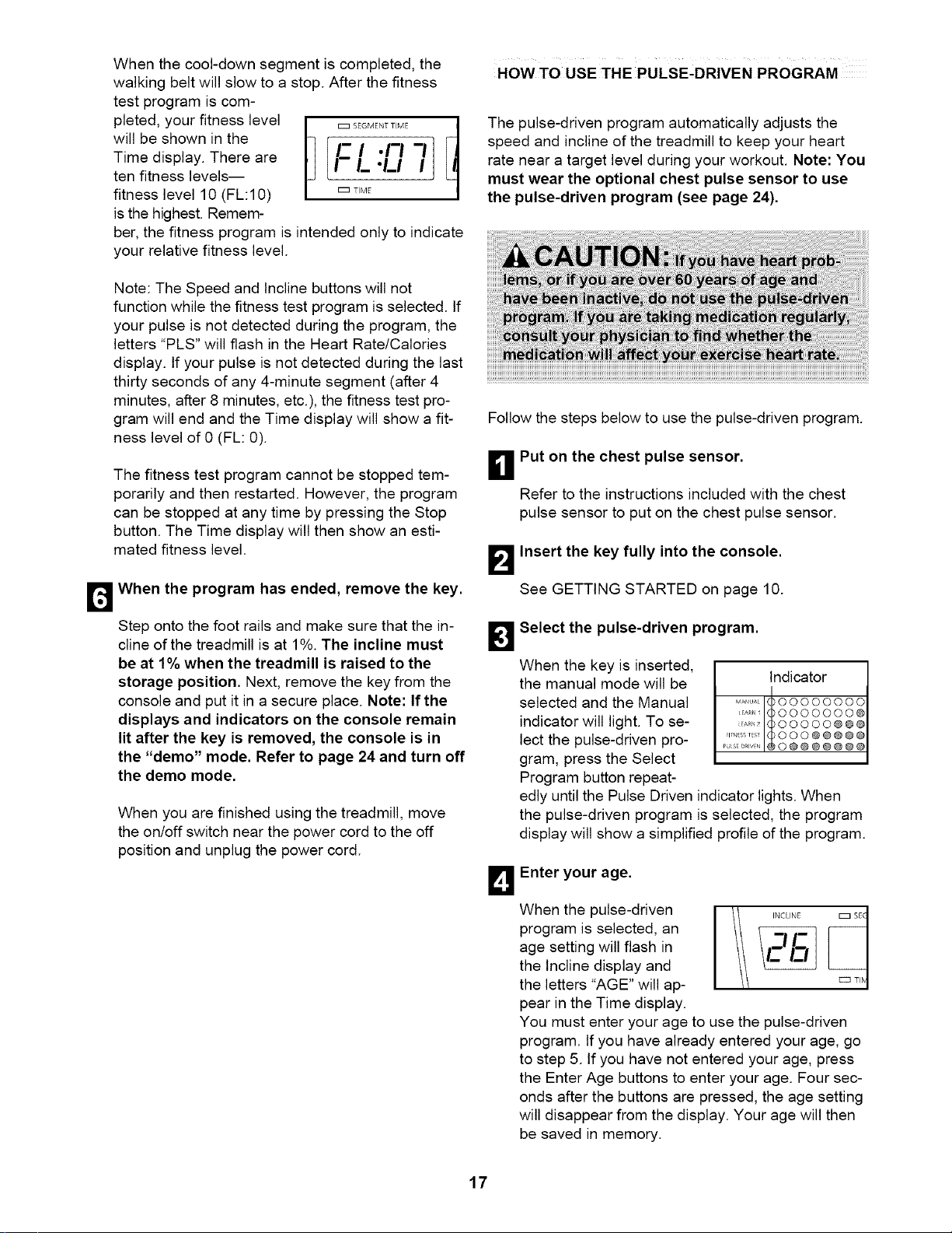
Select the fitness test program.
When the key is in-
serted, the manual
mode will be selected
and the Manual indica-
tor will light. To select
the fitness test program,
press the Select
Fit. Test Indicator
,,_A"UAL,OOOO0@O0
LE,_N '0000@@00
'_ 'OOQ@@@O0
__,ss_s, '00@@@@00
,uLs__v ,, 00@@@@@00
Program button repeatedly until the Fitness Test in-
dicator lights. When you select the fitness test pro-
gram, the program display will show a simplified
profile of the program.
B
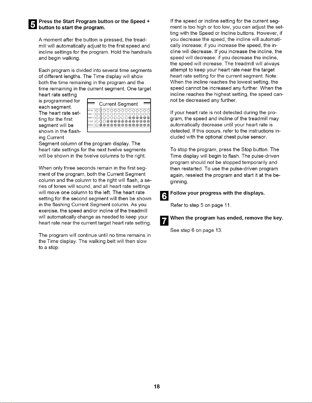
Enter your age.
When the fitness test
program is selected, an
age setting will flash in
the Incline display and
the letters "AGE" will
appear in the Time dis-
play. You must enter your age to use the fitness
test program. If you have already entered your
age, go to step 5. If you have not entered your
age, press the Enter Age buttons to enter your
age. Four seconds after the buttons are pressed,
the age setting will disappear from the display.
Your age will then be saved in memory.
_ ress the Start Program button or the Speed +
button to start the program.
When the button is
pressed, the Distance/
Laps display will show
an "L 1" (level 1), indicat-
ing that the first 4-minute
segment of the fitness
test program has begun. The incline of the tread-
mill will automatically adjust to 3% and the walking
belt will begin to move at 1.5 mph. Hold the
handrails and begin walking.
The fitness test program consists of seven 4-
minute segments and is followed by a 2-minute
cool-down segment. One speed setting and one
incline setting are pro-
grammed for each seg-
ment. The speed setting
for the first segment will
be shown in the flashing
Current Segment column
of the program display.
(The incline settings are
not shown in the program display.) The speed set-
tings for the remaining seven segments will be
shown in the seven columns to the right.
Current Segment
u,_ OO()O@@@@@OO(
',"_ OO()O@@@@@OO(
_ OO()@@@@@@OO(
s_ OO()@@@@@@OO(
R_VEOO_)@@@@@@@O(
When the first 4-minute segment of the fitness test
program is completed, all speed settings will move
one column to the left and the Distance/Laps dis-
play will show an '% 2/' indicating that the second
4-minute segment has begun. The incline will then
adjust to 4% and the speed will increase to 2.5
mph. When the second 4-minute segment is com-
pleted, the speed settings will again move one
column to the left and the Distance/Laps display
will show an '% 3." The incline will remain the
same, but the speed will then increase to 3.3 mph.
At the beginning of each 4-minute segment, the
speed and/or incline of the treadmill will automati-
cally increase. The fitness test program will con-
tinue in this way until your heart rate reaches 70%
of your estimated maximum heart rate, and the
current 4-minute segment is completed. The fit-
ness test program will then be completed, regard-
less of how many segments remain.
When the fitness test
program is completed,
the letter "C" will appear
in the Distance/Laps dis-
play, indicating that the
2-minute cool-down seg-
I _ DISTANCE ] q
I-
L.
LAPS
ment has begun. The incline will then adjust to 1%
and the speed will decrease to 1.2 mph.
16
When the cool-down segment is completed, the
walking belt will slow to a stop. After the fitness
test program is com-
pleted, your fitness level
will be shown in the
Time display. There are
ten fitness levels--
fitness level 10 (FL:10)
is the highest. Remem-
t l _ SEGMENT TIME ] 1
FL:LI/
TIME
ber, the fitness program is intended only to indicate
your relative fitness level.
Note: The Speed and Incline buttons will not
function while the fitness test program is selected. If
your pulse is not detected during the program, the
letters "PLS" will flash in the Heart Rate/Calories
display, tf your pulse is not detected during the last
thirty seconds of any 4-minute segment (after 4
minutes, after 8 minutes, etc.), the fitness test pro-
gram will end and the Time display will show a fit-
ness level of 0 (FL: 0).
The fitness test program cannot be stopped tem-
porarily and then restarted. However, the program
can be stopped at any time by pressing the Stop
button. The Time display will then show an esti-
mated fitness level.
r_ when the program has ended, remove the key.
Step onto the foot rails and make sure that the in-
cline of the treadmill is at 1%. The incline must
be at 1% when the treadmill is raised to the
storage position. Next, remove the key from the
console and put it in a secure place. Note: If the
displays and indicators on the console remain
lit after the key is removed, the console is in
the "demo" mode. Refer to page 24 and turn off
the demo mode.
When you are finished using the treadmill, move
the on/off switch near the power cord to the off
position and unplug the power cord.
H0WTO USE THE PuLsE:DRIVEN PROGRAM
The pulse-driven program automatically adjusts the
speed and incline of the treadmill to keep your heart
rate near a target level during your workout. Note: You
must wear the optional chest pulse sensor to use
the pulse-driven program (see page 24).
Follow the steps below to use the pulse-driven program.
_lPut on the chest pulse sensor.
Refer to the instructions included with the chest
pulse sensor to put on the chest pulse sensor.
B Insert the key fully into the console.
See GETTING STARTED on page 10.
lZl
Select the pulse-driven program.
When the key is inserted,
the manual mode will be
selected and the Manual
indicator will light. To se-
lect the pulse-driven pro-
gram, press the Select
Program button repeat-
Indicator
,,,,,_,u,,_,_O000000C
_,*,_, _O000000@
,_,__ _O0000@@@
INSSIS )000@@@@@
P_s_,v N _0@@@@@@@
edly until the Pulse Driven indicator lights. When
the pulse-driven program is selected, the program
display will show a simplified profile of the program.
B
Enter your age.
When the pulse-driven
program is selected, an
age setting will flash in
the Incline display and
the letters "AGE" will ap-
pear in the Time display.
You must enter your age to use the pulse-driven
program. If you have already entered your age, go
to step 5. tf you have not entered your age, press
the Enter Age buttons to enter your age. Four sec-
onds after the buttons are pressed, the age setting
will disappear from the display. Your age will then
be saved in memory.
17
_ ress the Start Program button or the Speed +
button to start the program.
A moment after the button is pressed, the tread-
mill will automatically adjust to the first speed and
incline settings for the program. Hold the handrails
and begin walking.
Each program is divided into several time segments
of different lengths. The Time display will show
both the time remaining in the program and the
time remaining in the current segment. One target
heart rate setting
is programmed for
each segment.
The heart rate set-
ting for the first
segment will be
shown in the flash-
ing Current
Segment column of the program display. The
heart rate settings for the next twelve segments
will be shown in the twelve columns to the right.
Current Segment m
,_UALO()OOOOO0000000C
_'"_ O()OOOO00OO0000C
,_20()0000000@@@@@@
Sl 0()0@@@@@(_@@@@@@
,WE_O_)@@@@@@@@@@@@@
When only three seconds remain in the first seg-
ment of the program, both the Current Segment
column and the column to the right will flash, a se-
ries of tones will sound, and all heart rate settings
will move one column to the left. The heart rate
setting for the second segment will then be shown
in the flashing Current Segment column. As you
exercise, the speed and/or incline of the treadmill
will automatically change as needed to keep your
heart rate near the current target heart rate setting.
The program will continue until no time remains in
the Time display. The walking belt will then slow
to a stop.
If the speed or incline setting for the current seg-
ment is too high or too low, you can adjust the set-
ting with the Speed or Incline buttons. However, if
you decrease the speed, the incline will automati-
cally increase; if you increase the speed, the in-
cline will decrease. If you increase the incline, the
speed will decrease; if you decrease the incline,
the speed will increase. The treadmill will always
attempt to keep your heart rate near the target
heart rate setting for the current segment. Note:
When the incline reaches the lowest setting, the
speed cannot be increased any further. When the
incline reaches the highest setting, the speed can-
not be decreased any further.
If your heart rate is not detected during the pro-
gram, the speed and incline of the treadmill may
automatically decrease until your heart rate is
detected. If this occurs, refer to the instructions in-
cluded with the optional chest pulse sensor.
To stop the program, press the Stop button. The
Time display will begin to flash. The pulse-driven
program should not be stopped temporarily and
then restarted. To use the pulse-driven program
again, reselect the program and start it at the be-
ginning.
r_ Follow your progress with the displays.
Refer to step 5 on page 11.
B hen the program has ended, remove the key.
See step 6 on page 13.
18
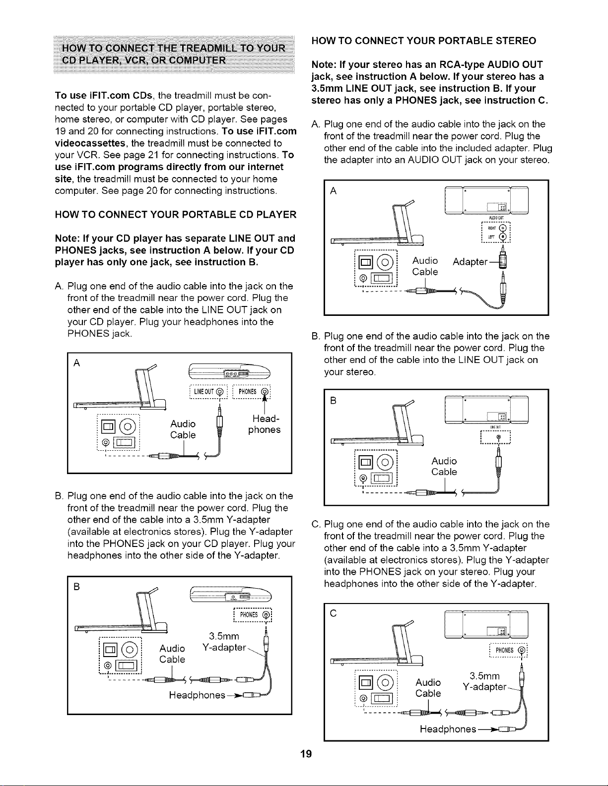
HOW TO CONNECT YOUR PORTABLE STEREO
To use iFIT.com CDs, the treadmill must be con-
nected to your portable CD player, portable stereo,
home stereo, or computer with CD player. See pages
19 and 20 for connecting instructions. To use iFIT.com
videocassettes, the treadmill must be connected to
your VCR. See page 21 for connecting instructions. To
use iFIT.com programs directly from our internet
site, the treadmill must be connected to your home
computer. See page 20 for connecting instructions.
HOW TO CONNECT YOUR PORTABLE CD PLAYER
Note: If your CD player has separate LINE OUT and
PHONES jacks, see instruction A below. If your CD
player has only one jack, see instruction B.
A. Plug one end of the audio cable into the jack on the
front of the treadmill near the power cord. Plug the
other end of the cable into the LINE OUT jack on
your CD player. Plug your headphones into the
PHONES jack.
A
' " "::1"_-](_i_' Audo r_' HJad,-
i _ k._i Cable W pnones
j
B. Plug one end of the audio cable into the jack on the
front of the treadmill near the power cord. Plug the
other end of the cable into a 3.5mm Y-adapter
(available at electronics stores). Plug the Y-adapter
into the PHONES jack on your CD player. Plug your
headphones into the other side of the Y-adapter.
i PHONES(_)!
]............. ¢.,
i
; 3.5mm
[](S]i Audio¥-adapter ;
@ _]i Cable ]!
Headphones_
Note: If your stereo has an RCA-type AUDIO OUT
jack, see instruction A below. If your stereo has a
3.5mm LINE OUT jack, see instruction B. If your
stereo has only a PHONES jack, see instruction C.
A. Plug one end of the audio cable into the jack on the
front of the treadmill near the power cord. Plug the
other end of the cable into the included adapter. Plug
the adapter into an AUDIO OUT jack on your stereo.
,..2_22L...
i_':: i
Aud,oAdapterq
Cab,e ,
B. Plug one end of the audio cable into the jack on the
front of the treadmill near the power cord. Plug the
other end of the cable into the LINE OUT jack on
your stereo.
,t................ I
i ©i Audio
(_ [_i Cable
,--,,...... __ _
UN_0U_
i......_...J
C. Plug one end of the audio cable into the jack on the
front of the treadmill near the power cord. Plug the
other end of the cable into a 3.5mm Y-adapter
(available at electronics stores). Plug the Y-adapter
into the PHONES jack on your stereo. Plug your
headphones into the other side of the Y-adapter.
o
Cab,e ¥-adapier--_
................... Headphones
19
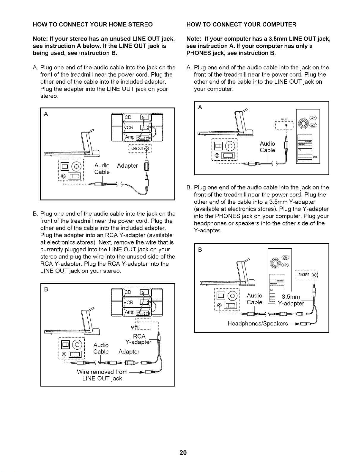
HOW TO CONNECT YOUR HOME STEREO HOW TO CONNECT YOUR COMPUTER
Note: If your stereo has an unused LINE OUT jack,
see instruction A below. If the LINE OUT jack is
being used, see instruction B.
A. Plug one end of the audio cable into the jack on the
front of the treadmill near the power cord. Plug the
other end of the cable into the included adapter.
Plug the adapter into the LINE OUT jack on your
stereo.
°CD °
i
B. Plug one end of the audio cable into the jack on the
front of the treadmill near the power cord. Plug the
other end of the cable into the included adapter.
Plug the adapter into an RCA Y-adapter (available
at electronics stores). Next, remove the wire that is
currently plugged into the LINE OUT jack on your
stereo and plug the wire into the unused side of the
RCA Y-adapter. Plug the RCA Y-adapter into the
LINE OUT jack on your stereo.
i[]© AudioY-adapte --
@{._ Cable Adapter
>mp
RCA
Wire removed from _c::_,,_
LINE OUT jack
Note: If your computer has a 3.5mm LINE OUT jack,
see instruction A. If your computer has only a
PHONES jack, see instruction B.
A. Plug one end of the audio cable into the jack on the
front of the treadmill near the power cord. Plug the
other end of the cable into the LINE OUT jack on
your computer.
A
L]N_OU_
....... i .....
i
i
"_J i Cable '_
&
i
ooo
B. Plug one end of the audio cable into the jack on the
front of the treadmill near the power cord. Plug the
other end of the cable into a 3.5mm Y-adapter
(available at electronics stores). Plug the Y-adapter
into the PHONES jack on your computer. Plug your
headphones or s )eakers into the other side of the
Y-adapter.
B
[] © Audio
@ [_ : Cable Z Y-adapter
m
3.5mm
Headphones/Speakers-_--_
20
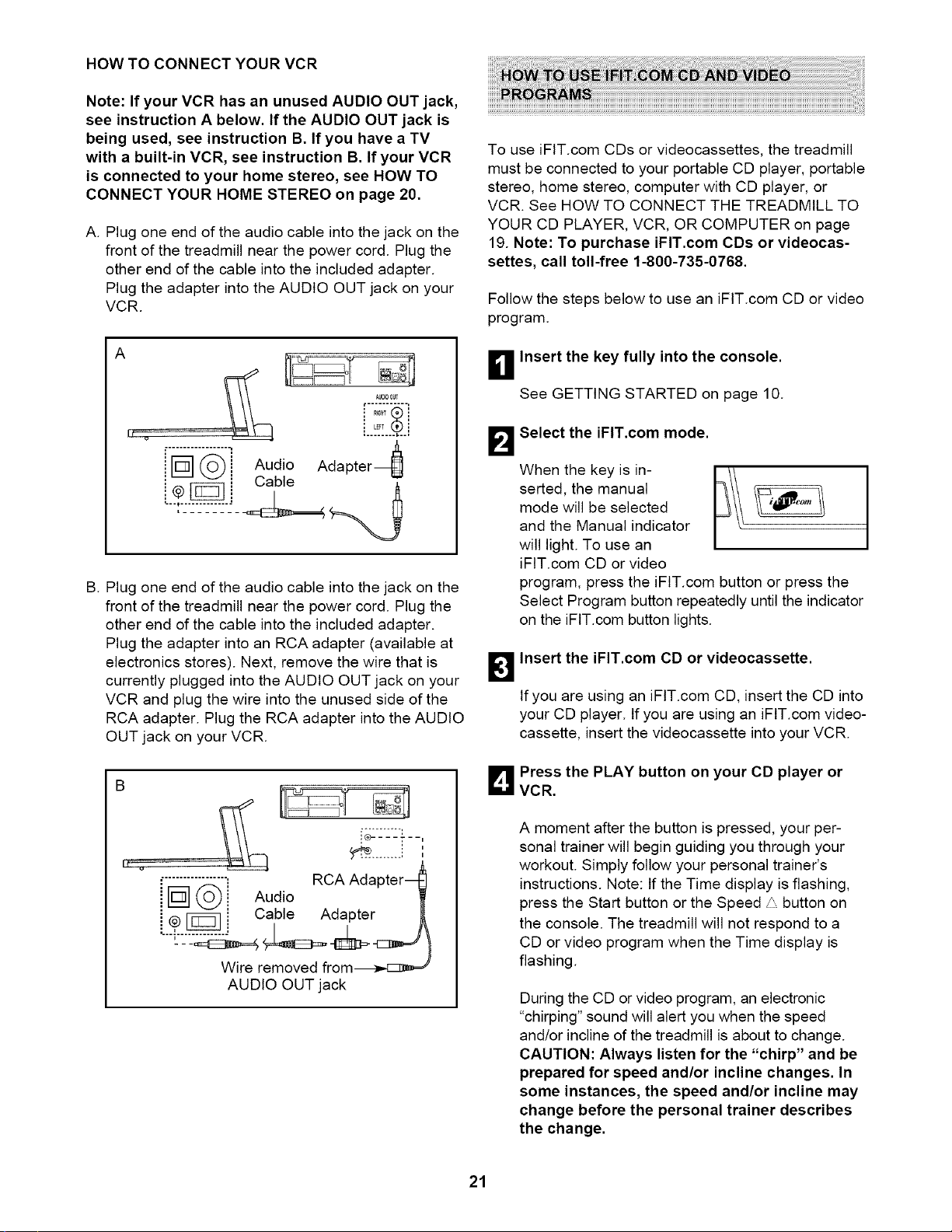
HOW TO CONNECT YOUR VCR
Note: If your VCR has an unused AUDIO OUT jack,
see instruction A below. If the AUDIO OUT jack is
being used, see instruction B. If you have a TV
with a built-in VCR, see instruction B. If your VCR
is connected to your home stereo, see HOW TO
CONNECT YOUR HOME STEREO on page 20.
A. Plug one end of the audio cable into the jack on the
front of the treadmill near the power cord. Plug the
other end of the cable into the included adapter.
Plug the adapter into the AUDIO OUT jack on your
VCR.
B. Plug one end of the audio cable into the jack on the
front of the treadmill near the power cord. Plug the
other end of the cable into the included adapter.
Plug the adapter into an RCA adapter (available at
electronics stores). Next, remove the wire that is
currently plugged into the AUDIO OUT jack on your
VCR and plug the wire into the unused side of the
RCA adapter. Plug the RCA adapter into the AUDIO
OUT jack on your VCR.
B
,ft___........==',
i
..."' ' '_;:_. RCA Adapter_
IIDI CO) Audio
_ Cable Adapter
[_[_ _ ._r.c _
--_--_--_-_
Wire removed from_
AUDIO OUT jack
To use iFtT.com CDs or videocassettes, the treadmill
must be connected to your portable CD player, portable
stereo, home stereo, computer with CD player, or
VCR. See HOW TO CONNECT THE TREADMILL TO
YOUR CD PLAYER, VCR, OR COMPUTER on page
19. Note: To purchase iFIT.com CDs or videocas-
settes, call toll-free 1-800-735-0768.
Follow the steps below to use an iFIT.com CD or video
program.
_1 Insert the key fully into the console.
See GETTING STARTED on page 10.
B Select the iFIT.com mode.
When the key is in- I //
serted, the manual
F
mode will be selected
and the Manual indicator
will light. To use an
iFIT.com CD or video
program, press the iFIT.com button or press the
Select Program button repeatedly until the indicator
on the iFtT.com button lights.
D
Insert the iFIT.com CD or videocassette.
If you are using an iFIT.com CD, insert the CD into
your CD player. If you are using an iFIT.com video-
cassette, insert the videocassette into your VCR.
B ress the PLAY button on your CD player or
VCR.
A moment after the button is pressed, your per-
sonal trainer will begin guiding you through your
workout. Simply follow your personal trainer's
instructions. Note: tfthe Time display is flashing,
press the Start button or the Speed/_, button on
the console. The treadmill will not respond to a
CD or video program when the Time display is
flashing.
During the CD or video program, an electronic
"chirping" sound will alert you when the speed
and/or incline of the treadmill is about to change.
CAUTION: Always listen for the "chirp" and be
prepared for speed and/or incline changes. In
some instances, the speed and/or incline may
change before the personal trainer describes
the change.
21
If the speed or incline settings are too high or too
low, you can manually override the settings at any
time by pressing the Speed or Incline buttons on
the console. However, when the next "chirp" is
heard, the speed and/or incline will change to
the next settings of the CD or video program.
To stop the walking belt at any time, press the
Stop button on the console. The Time display will
begin to flash. To restart the program, press the
Start Program button or the Speed + button. After
a moment, the walking belt will begin to move at
1.0 mph. When the next "chirp" is heard, the
speed and incline will change to the next set-
tings of the CD or video program.
When the CD or video program is completed, the
walking belt will stop and the Time display will
begin to flash. Note: To use another CD or video
program, press the Stop button or remove the key
and go to step 1 on page 18.
Note: If the speed or incline of the treadmill
does not change when a "chirp" is heard:
• make sure that the iFIT.com indicator is lit and
that the Time display is not flashing. If the
Time display is flashing, press the Start but-
ton or the Speed A button on the console
• adjust the volume of your CD player or VCR. If
the volume is too high or too low, the console
may not detect the program signals
• make sure that the audio cable is properly
connected, that it is fully plugged in, and that
it is not wrapped around a power cord
• if you are using your portable CD player and
the CD skips, set the CD player on the floor or
another fiat surface instead of on the console.
• See the bottom of page 27.
_ ollow your progress with the LED track and
the displays.
See step 5 on page 11.
r_ Measure your heart rate, if desired.
Refer to step 6 on page 12.
B hen the program has ended, remove the key.
See step 6 on page 13.
CAUTION: Always remove iFIT.com CDs and
videocassettes from your CD player or VCR
when you are finished using them.
22
Our Web site at www.iFtT.com allows you to access
basic programs, audio programs, and video programs
directly from the internet. Additional options are soon
to be available. See www.iFIT.com for details.
To use programs from our Web site, the treadmill must
be connected to your home computer. See HOW TO
CONNECT YOUR COMPUTER on page 20. In
addition, you must have an internet connection and
an internet service provider. A list of specific system
requirements will be found on our Web site.
Follow the steps below to use a program from our
Web site.
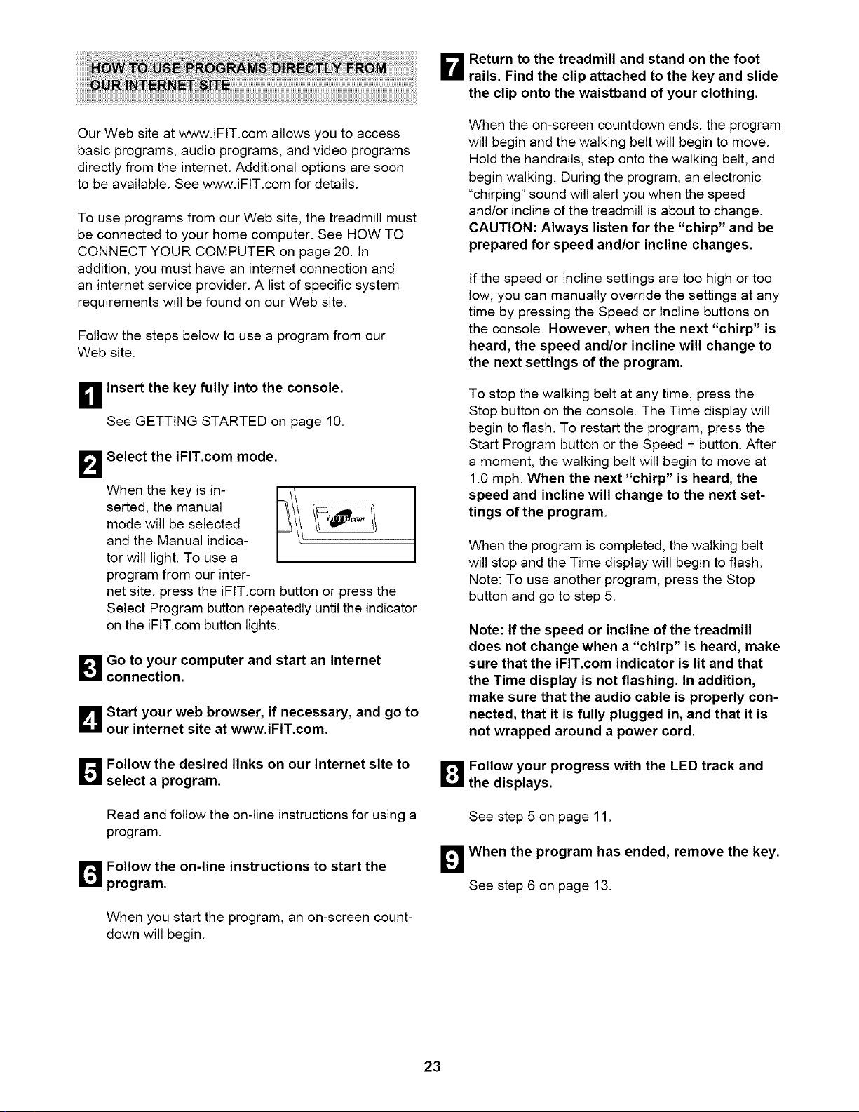
_1 Insert the key fully into the console.
See GETTING STARTED on page 10.
FI
Select the iFIT.com mode.
When the key is in-
serted, the manual
mode will be selected
and the Manual indica-
tor will light. To use a
program from our inter-
net site, press the iFtT.com button or press the
Select Program button repeatedly until the indicator
on the iFIT.com button lights.
_lGo to your computer and start an internet
connection.
B tart your web browser, if necessary, and go to
our internet site at www.iFIT.com.
_ ollow the desired links on our internet site to
select a program.
Read and follow the on-line instructions for using a
program.
r_ Follow the on-line instructions to start the
program.
When you start the program, an on-screen count-
down will begin.
B eturn to the treadmill and stand on the foot
rails. Find the clip attached to the key and slide
the clip onto the waistband of your clothing.
When the on-screen countdown ends, the program
will begin and the walking belt will begin to move.
Hold the handrails, step onto the walking belt, and
begin walking. During the program, an electronic
"chirping" sound will alert you when the speed
and/or incline of the treadmill is about to change.
CAUTION: Always listen for the "chirp" and be
prepared for speed and/or incline changes.
If the speed or incline settings are too high or too
low, you can manually override the settings at any
time by pressing the Speed or Incline buttons on
the console. However, when the next "chirp" is
heard, the speed and/or incline will change to
the next settings of the program.
To stop the walking belt at any time, press the
Stop button on the console. The Time display will
begin to flash. To restart the program, press the
Start Program button or the Speed + button. After
a moment, the walking belt will begin to move at
1.0 mph. When the next "chirp" is heard, the
speed and incline will change to the next set-
tings of the program.
When the program is completed, the walking belt
will stop and the Time display will begin to flash.
Note: To use another program, press the Stop
button and go to step 5.
Note: If the speed or incline of the treadmill
does not change when a "chirp" is heard, make
sure that the iFiT.com indicator is lit and that
the Time display is not flashing. In addition,
make sure that the audio cable is properly con-
nected, that it is fully plugged in, and that it is
not wrapped around a power cord.
_ ollow your progress with the LED track and
the displays.
See step 5 on page 11.
1_1 When the program has ended, remove the key.
See step 6 on page 13.
23
THE INFORMATION MODE/DEMO MODE THE OPTIONAL CHEST PULSE SENSOR
The console features an information mode that keeps
track of the total number of hours that the treadmill has
been operated and the total number of miles that the
walking belt has moved. The information mode also
allows you to switch the console from miles per hour to
kilometers per hour. In addition, the information mode
allows you to turn on and turn off the demo mode.
To select the information mode, hold down the Stop
button while inserting the key into the console. When
the information mode is selected, the following informa-
tion will be shown:
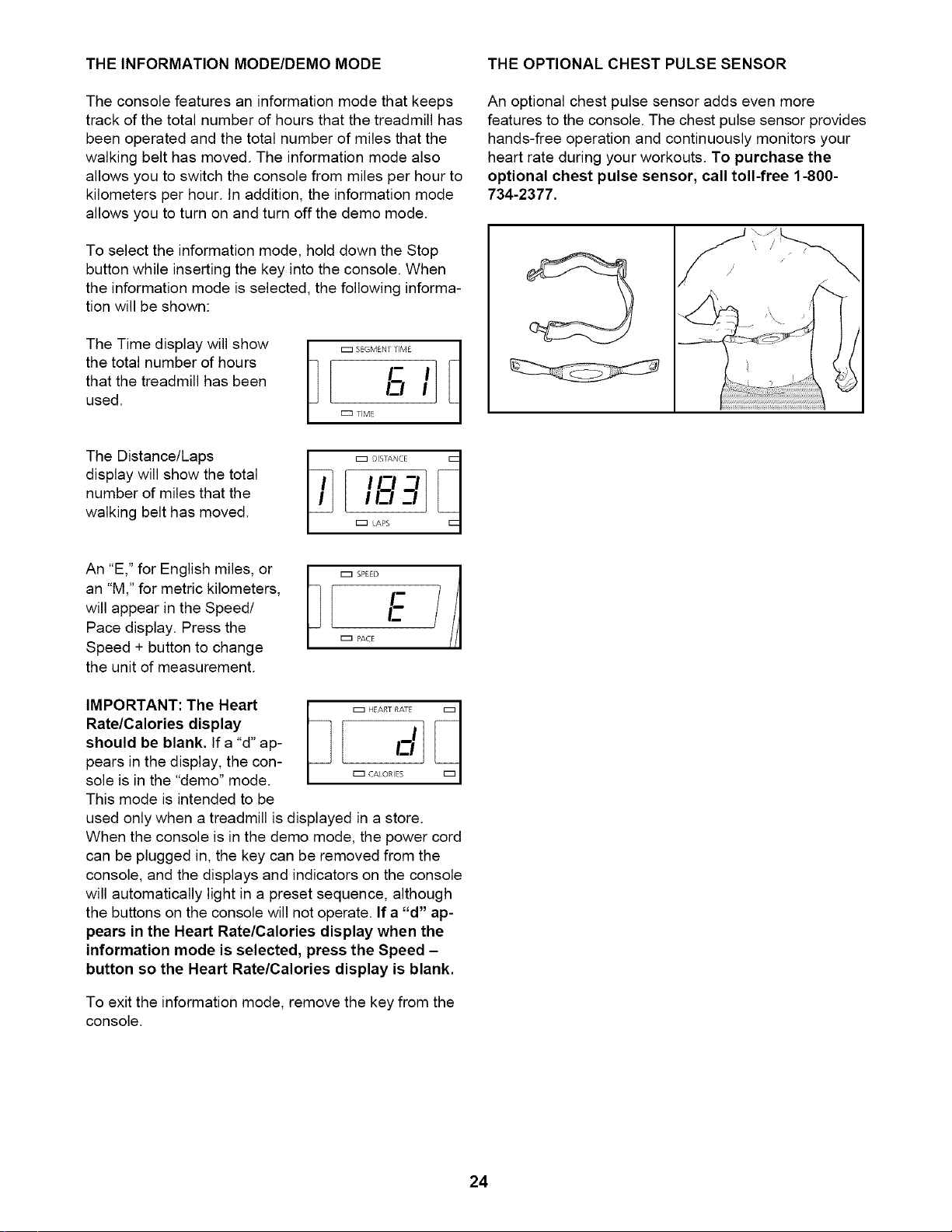
TheT e,spa wshowl ,jl
the total number of hours
that the treadmill has been
used.
EC3 TIME
The Distance/Laps
display will show the total
number of miles that the
walking belt has moved.
An optional chest pulse sensor adds even more
features to the console. The chest pulse sensor provides
hands-free operation and continuously monitors your
heart rate during your workouts. To purchase the
optional chest pulse sensor, call toll-free 1-800-
734-2377.
/
An "E," for English miles, or _ I _ sPEEDE
an "M," for metric kilometers,
will appear in the Speed/
Pace display. Press the
Speed + button to change _ _ACE
the unit of measurement.
IMPORTANT: The Heart
Rate/Calories display
should be blank. If a "d" ap-
pears in the display, the con-
sole is in the "demo" mode.
This mode is intended to be
used only when a treadmill is displayed in a store.
When the console is in the demo mode, the power cord
can be plugged in, the key can be removed from the
console, and the displays and indicators on the console
will automatically light in a preset sequence, although
the buttons on the console will not operate. If a "d" ap-
pears in the Heart Rate/Calories display when the
information mode is selected, press the Speed -
button so the Heart Rate/Calories display is blank.
To exit the information mode, remove the key from the
console.
24
HOW TO FOLD AND MOVE THE TREADMILL
HOW TO FOLD THE TREADMILL FOR STORAGE
Before folding the treadmill, adjust the incline to the
lowest position. Ifthis is not done, the treadmill may be per-
manently damaged. Remove the key and unplug the power
cord. CAUTION: You must be able to safely lift 45 pounds
(20 kg) in order to raise, lower, or move the treadmill.
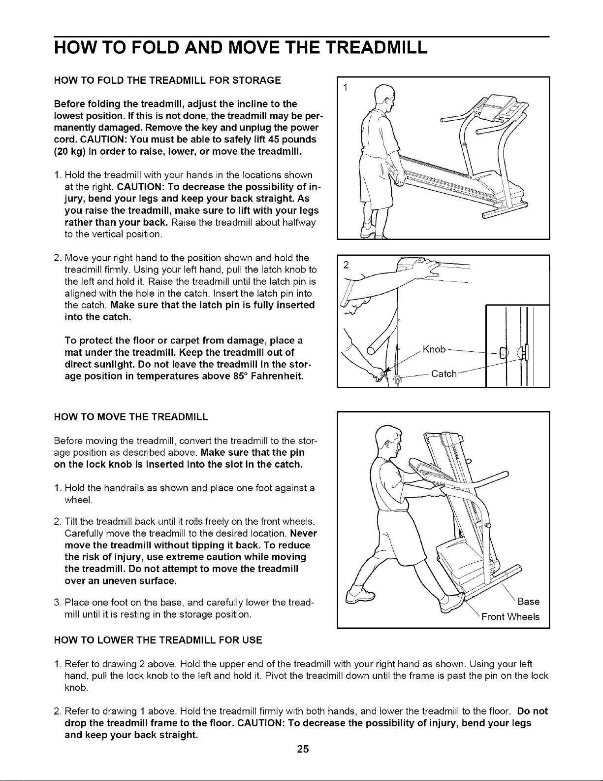
1. Hold the treadmill with your hands in the locations shown
at the right. CAUTION: To decrease the possibility of in-
jury, bend your legs and keep your back straight. As
you raise the treadmill, make sure to lift with your legs
rather than your back. Raise the treadmill about halfway
to the vertical position.
2. Move your right hand to the position shown and hold the
treadmill firmly. Using your left hand, pull the latch knob to
the left and hold it. Raise the treadmill until the latch pin is
aligned with the hole in the catch. Insert the latch pin into
the catch. Make sure that the latch pin is fully inserted
into the catch.
To protect the floor or carpet from damage, place a
mat under the treadmill. Keep the treadmill out of
direct sunlight. Do not leave the treadmill in the stor-
age position in temperatures above 85° Fahrenheit.
HOW TO MOVE THE TREADMILL
Before moving the treadmill, convert the treadmill to the stor-
age position as described above. Make sure that the pin
on the lock knob is inserted into the slot in the catch.
1. Hold the handrails as shown and place one foot against a
wheel.
2. Tilt the treadmill back until it rolls freely on the front wheels.
Carefully move the treadmill to the desired location. Never
move the treadmill without tipping it back. To reduce
the risk of injury, use extreme caution while moving
the treadmill. Do not attempt to move the treadmill
over an uneven surface.
3. Place one foot on the base, and carefully lower the tread-
mill until it is resting in the storage position.
HOW TO LOWER THE TREADMILL FOR USE
1. Refer to drawing 2 above. Hold the upper end of the treadmill with your right hand as shown. Using your left
hand, pull the lock knob to the left and hold it. Pivot the treadmill down until the frame is past the pin on the lock
knob.
2. Refer to drawing 1 above. Hold the treadmill firmly with both hands, and lower the treadmill to the floor. Do not
drop the treadmill frame to the floor. CAUTION: To decrease the possibility of injury, bend your legs
and keep your back straight.
25
TROUBLE-SHOOTING
Most treadmill problems can be solved by following the steps below. Find the symptom that applies, and
follow the steps listed. If further assistance is needed, please call our Customer Service Department toll-
free at 1-888-825-2588, Monday through Friday, 6 a.m. until 6 p.m. Mountain Time (excluding holidays).
PROBLEM: The power does not turn on
SOLUTION: a.
Make sure that the power cord is plugged into a surge suppressor, and that the surge suppressor
is plugged into a properly grounded outlet (see page 8). Use only a single-outlet surge suppressor
that meets all of the specifications described on page 8. Important: The treadmill is not compatible
with GFCl-equipped outlets.
b. After the power cord has been plugged in, make sure that the key is fully inserted into the console.
C.
d.
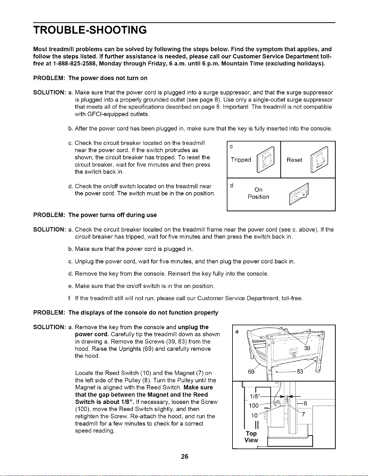
Check the circuit breaker located on the treadmill
near the power cord. If the switch protrudes as
shown, the circuit breaker has tripped. To reset the
circuit breaker, wait for five minutes and then press
the switch back in.
Check the on/off switch located on the treadmill near
the power cord. The switch must be in the on position.
C
Tripped
Reset
on
Position
PROBLEM: The power turns off during use
SOLUTION: a. Check the circuit breaker located on the treadmill frame near the power cord (see c. above). If the
circuit breaker has tripped, wait for five minutes and then press the switch back in.
b. Make sure that the power cord is plugged in.
c. Unplug the power cord, wait for five minutes, and then plug the power cord back in.
d. Remove the key from the console. Reinsert the key fully into the console.
e. Make sure that the on/off switch is in the on position.
f. If the treadmill still will not run, please call our Customer Service Department, toll-free.
PROBLEM: The displays of the console do not function properly
SOLUTION: a.
Remove the key from the console and unplug the
power cord. Carefully tip the treadmill down as shown
in drawing a. Remove the Screws (39, 83) from the
hood. Raise the Uprights (69) and carefully remove
the hood.
Locate the Reed Switch (10) and the Magnet (7) on
the left side of the Pulley (8). Turn the Pulley until the
Magnet is aligned with the Reed Switch. Make sure
that the gap between the Magnet and the Reed
Switch is about 1/8". If necessary, loosen the Screw
(100), move the Reed Switch slightly, and then
retighten the Screw. Re-attach the hood, and run the
treadmill for a few minutes to check for a correct
speed reading.
26
U
1
1/8"--
1 )0_
Top
View
r
--8
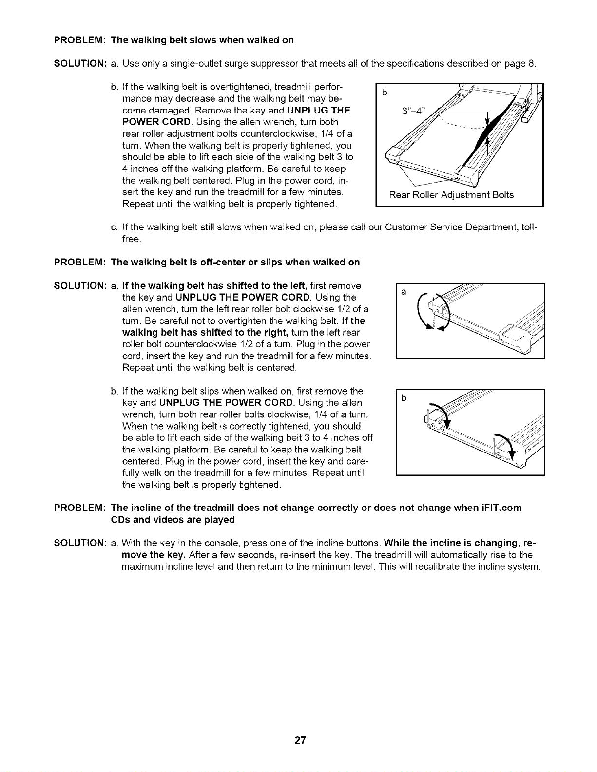
PROBLEM: The walking belt slows when walked on
SOLUTION: a. Use only a single-outlet surge suppressor that meets all of the specifications described on page 8.
b.
If the walking belt is overtightened, treadmill perfor-
mance may decrease and the walking belt may be-
come damaged. Remove the key and UNPLUG THE
POWER CORD. Using the allen wrench, turn both
rear roller adjustment bolts counterclockwise, 1/4 of a
turn. When the walking belt is properly tightened, you
should be able to lift each side of the walking belt 3 to
4 inches off the walking platform. Be careful to keep
the walking belt centered. Plug in the power cord, in-
sert the key and run the treadmill for a few minutes.
Repeat until the walking belt is properly tightened.
Rear Roller Adjustment Bolts
c. If the walking belt still slows when walked on, please call our Customer Service Department, toll-
free.
PROBLEM: The walking belt is off-center or slips when walked on
SOLUTION: a.
If the walking belt has shifted to the left, first remove
the key and UNPLUG THE POWER CORD. Using the
allen wrench, turn the left rear roller bolt clockwise 1/2 of a
turn. Be careful not to overtighten the walking belt. If the
walking belt has shifted to the right, turn the left rear
roller bolt counterclockwise 1/2 of a turn. Plug in the power
cord, insert the key and run the treadmill for a few minutes.
Repeat until the walking belt is centered.
b.
If the walking belt slips when walked on, first remove the
key and UNPLUG THE POWER CORD. Using the allen
wrench, turn both rear roller bolts clockwise, 1/4 of a turn.
When the walking belt is correctly tightened, you should
be able to lift each side of the walking belt 3 to 4 inches off
the walking platform. Be careful to keep the walking belt
centered. Plug in the power cord, insert the key and care-
fully walk on the treadmill for a few minutes. Repeat until
the walking belt is properly tightened.
PROBLEM: The incline of the treadmill does not change correctly or does not change when iFIT.com
CDs and videos are played
SOLUTION: a. With the key in the console, press one of the incline buttons. While the incline is changing, re-
move the key. After a few seconds, re-insert the key. The treadmill will automatically rise to the
maximum incline level and then return to the minimum level. This will recalibrate the incline system.
27
CONDITIONING GUIDELINES
The following guidelines will help you to plan your ex-
ercise program. Remember--these are general guide-
lines only. For more detailed exercise information, ob-
tain a reputable book or consult your physician.
EXERCISE INTENSITY
Whether your goal is to burn fat or to strengthen your
cardiovascular system, the key to achieving the
desired results is to exercise with the proper intensity.
The proper intensity level can be found by using your
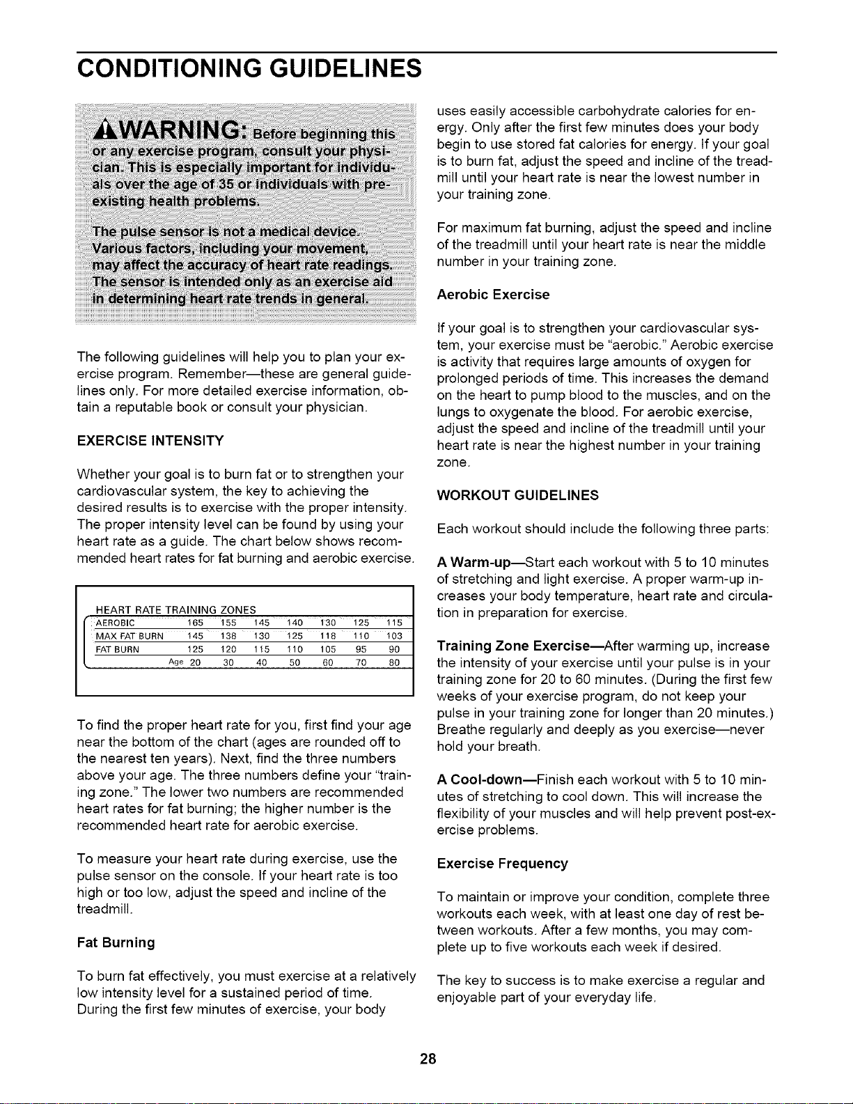
heart rate as a guide. The chart below shows recom-
mended heart rates for fat burning and aerobic exercise.
HEART RATE TRAINING ZONES
[ AEROBIC 165 155 145 140 130 125 115
MAX FAT BURN 145 138 130 125 118 110 103
FAT BURN 125 120 115 110 105 95 90
Age 20 30 40 50 60 70 80
To find the proper heart rate for you, first find your age
near the bottom of the chart (ages are rounded off to
the nearest ten years). Next, find the three numbers
above your age. The three numbers define your "train-
ing zone." The lower two numbers are recommended
heart rates for fat burning; the higher number is the
recommended heart rate for aerobic exercise.
To measure your heart rate during exercise, use the
pulse sensor on the console. If your heart rate is too
high or too low, adjust the speed and incline of the
treadmill.
Fat Burning
To burn fat effectively, you must exercise at a relatively
low intensity level for a sustained period of time.
During the first few minutes of exercise, your body
uses easily accessible carbohydrate calories for en-
ergy. Only after the first few minutes does your body
begin to use stored fat calories for energy. If your goal
is to burn fat, adjust the speed and incline of the tread-
mill until your heart rate is near the lowest number in
your training zone.
For maximum fat burning, adjust the speed and incline
of the treadmill until your heart rate is near the middle
number in your training zone.
Aerobic Exercise
If your goal is to strengthen your cardiovascular sys-
tem, your exercise must be "aerobic." Aerobic exercise
is activity that requires large amounts of oxygen for
prolonged periods of time. This increases the demand
on the heart to pump blood to the muscles, and on the
lungs to oxygenate the blood. For aerobic exercise,
adjust the speed and incline of the treadmill until your
heart rate is near the highest number in your training
zone.
WORKOUT GUIDELINES
Each workout should include the following three parts:
A Warm-up--Start each workout with 5 to 10 minutes
of stretching and light exercise. A proper warm-up in-
creases your body temperature, heart rate and circula-
tion in preparation for exercise.
Training Zone Exercise--After warming up, increase
the intensity of your exercise until your pulse is in your
training zone for 20 to 60 minutes. (During the first few
weeks of your exercise program, do not keep your
pulse in your training zone for longer than 20 minutes.)
Breathe regularly and deeply as you exercise--never
hold your breath.
A Cool-down--Finish each workout with 5 to 10 min-
utes of stretching to cool down. This will increase the
flexibility of your muscles and will help prevent post-ex-
ercise problems.
Exercise Frequency
To maintain or improve your condition, complete three
workouts each week, with at least one day of rest be-
tween workouts. After a few months, you may com-
plete up to five workouts each week if desired.
The key to success is to make exercise a regular and
enjoyable part of your everyday life.
28
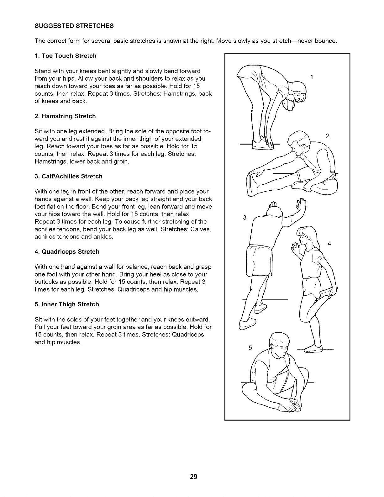
SUGGESTED STRETCHES
The correct form for several basic stretches is shown at the right. Move slowly as you stretch--never bounce.
1. Toe Touch Stretch
Stand with your knees bent slightly and slowly bend forward
from your hips. Allow your back and shoulders to relax as you
reach down toward your toes as far as possible. Hold for 15
counts, then relax. Repeat 3 times. Stretches: Hamstrings, back
of knees and back.
2. Hamstring Stretch
Sit with one leg extended. Bring the sole of the opposite foot to-
ward you and rest it against the inner thigh of your extended
leg. Reach toward your toes as far as possible. Hold for 15
counts, then relax. Repeat 3 times for each leg. Stretches:
Hamstrings, lower back and groin.
3. Calf/Achilles Stretch
With one leg in front of the other, reach forward and place your
hands against a wall. Keep your back leg straight and your back
foot fiat on the floor. Bend your front leg, lean forward and move
your hips toward the wall. Hold for 15 counts, then relax.
Repeat 3 times for each leg. To cause further stretching of the
achilles tendons, bend your back leg as well. Stretches: Calves,
achilles tendons and ankles.
4. Quadriceps Stretch
With one hand against a wall for balance, reach back and grasp
one foot with your other hand. Bring your heel as close to your
buttocks as possible. Hold for 15 counts, then relax. Repeat 3
times for each leg. Stretches: Quadriceps and hip muscles.
5. Inner Thigh Stretch
Sit with the soles of your feet together and your knees outward.
Pull your feet toward your groin area as far as possible. Hold for
15 counts, then relax. Repeat 3 times. Stretches: Quadriceps
and hip muscles.
1
29
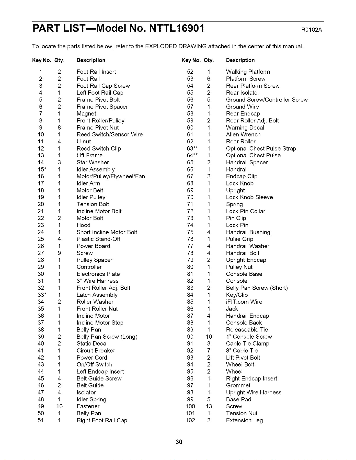
PART LISTmModel No. NTTL16901 R0102A
To locate the parts listed below, refer to the EXPLODED DRAWING attached in the center of this manual.
Key No. Qty. Description KeyNo. Qty.
1 2 Foot Rail Insert 52 1
2 2 Foot Rail 53 6
3 2 Foot Rail Cap Screw 54 2
4 1 Left Foot Rail Cap 55 2
5 2 Frame Pivot Bolt 56 5
6 2 Frame Pivot Spacer 57 1
7 1 Magnet 58 1
8 1 Front Roller/Pulley 59 2
9 8 Frame Pivot Nut 60 1
10 1 Reed Switch/Sensor Wire 61 1
11 4 U-nut 62 1
12 1 Reed Switch Clip 63** 1
13 1 Lift Frame 64** 1
14 3 Star Washer 65 2
15" 1 Idler Assembly 66 1
16 1 MotorlPulleylFlywheellFan 67 2
17 1 Idler Arm 68 1
18 1 Motor Belt 69 1
19 1 Idler Pulley 70 1
20 1 Tension Bolt 71 1
21 1 Incline Motor Bolt 72 1
22 2 Motor Bolt 73 1
23 1 Hood 74 1
24 1 Short Incline Motor Bolt 75 4
25 4 Plastic Stand-Off 76 1
26 1 Power Board 77 4
27 9 Screw 78 4
28 1 Pulley Spacer 79 2
29 1 Controller 80 1
30 1 Electronics Plate 81 1
31 1 8" Wire Harness 82 1
32 1 Front Roller Adj. Bolt 83 2
33* 1 Latch Assembly 84 1
34 2 Roller Washer 85 1
35 1 Front Roller Nut 86 1
36 1 Incline Motor 87 4
37 1 Incline Motor Stop 88 1
38 1 Belly Pan 89 1
39 2 Belly Pan Screw (Long) 90 10
40 2 Static Decal 91 3
41 1 Circuit Breaker 92 7
42 1 Power Cord 93 2
43 1 On/Off Switch 94 2
44 1 Left Endcap Insert 95 2
45 4 Belt Guide Screw 96 1
46 2 Belt Guide 97 1
47 4 Isolator 98 1
48 1 Idler Spring 99 5
49 16 Fastener 100 13
50 1 Belly Pan 101 1
51 1 Right Foot Rail Cap 102 2
Description
Walking Platform
Platform Screw
Rear Platform Screw
Rear Isolator
Ground Screw/Controller Screw
Ground Wire
Rear Endcap
Rear Roller Adj. Bolt
Warning Decal
Allen Wrench
Rear Roller
Optional Chest Pulse Strap
Optional Chest Pulse
Handrail Spacer
Handrail
Endcap Clip
Lock Knob
Upright
Lock Knob Sleeve
Spring
Lock Pin Collar
Pin Clip
Lock Pin
Handrail Bushing
Pulse Grip
Handrail Washer
Handrail Bolt
Upright Endcap
Pulley Nut
Console Base
Console
Belly Pan Screw (Short)
Key/Clip
iFIT.com Wire
Jack
Handrail Endcap
Console Back
Releaseable Tie
1" Console Screw
Cable Tie Clamp
8" Cable Tie
Lift Pivot Bolt
Wheel Bolt
Wheel
Right Endcap Insert
Grommet
Upright Wire Harness
Base Pad
Screw
Tension Nut
Extension Leg
30
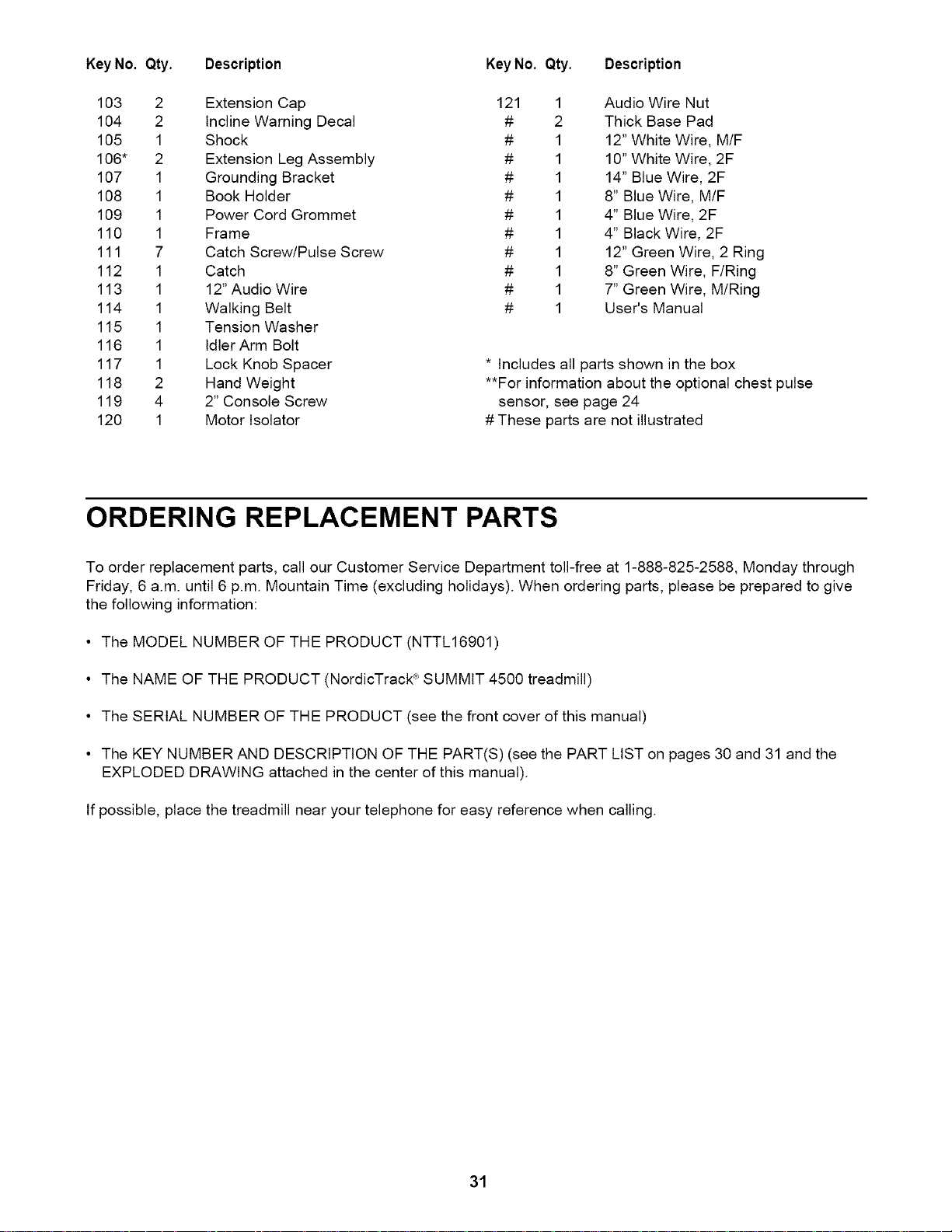
Key No. Qty. Description KeyNo. Qty. Description
103 2 Extension Cap
104 2 Incline Warning Decal
105 1 Shock
106" 2 Extension Leg Assembly
107 1 Grounding Bracket
108 1 Book Holder
109 1 Power Cord Grommet
110 1 Frame
111 7 Catch Screw/Pulse Screw
112 1 Catch
113 1 12" Audio Wire
114 1 Walking Belt
115 1 Tension Washer
116 1 Idler Arm Bolt
117 1 Lock Knob Spacer
118 2 Hand Weight
119 4 2" Console Screw
120 1 Motor Isolator
121 1 Audio Wire Nut
# 2 Thick Base Pad
# 1 12" White Wire, M/F
# 1 10" White Wire, 2F
# 1 14" Blue Wire, 2F
# 1 8" Blue Wire, M/F
# 1 4" Blue Wire, 2F
# 1 4" Black Wire, 2F
# 1 12" Green Wire, 2 Ring
# 1 8" Green Wire, FIRing
# 1 7" Green Wire, MIRing
# 1 User's Manual
* Includes all parts shown in the box
**For information about the optional chest pulse
sensor, see page 24
# These parts are not illustrated
ORDERING REPLACEMENT PARTS
To order replacement parts, call our Customer Service Department toll-free at 1-888-825-2588, Monday through
Friday, 6 a.m. until 6 p.m. Mountain Time (excluding holidays). When ordering parts, please be prepared to give
the following information:
• The MODEL NUMBER OF THE PRODUCT (NTTL16901)
• The NAME OF THE PRODUCT (NordicTrack '_SUMMIT 4500 treadmill)
• The SERIAL NUMBER OF THE PRODUCT (see the front cover of this manual)
• The KEY NUMBER AND DESCRIPTION OF THE PART(S) (see the PART LIST on pages 30 and 31 and the
EXPLODED DRAWING attached in the center of this manual).
If possible, place the treadmill near your telephone for easy reference when calling.
31
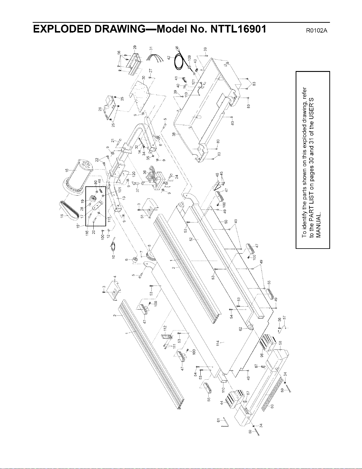
EXPLODED DRAWINGmModel No. NTTL16901 R0_02A
/ ,//
/ /
\
/ \
/ \
\
/
/
03
.- LLI
_co
_D
"O ¢"
"o
03 c-
_O
03
O
r-
m c
m 0
_o__
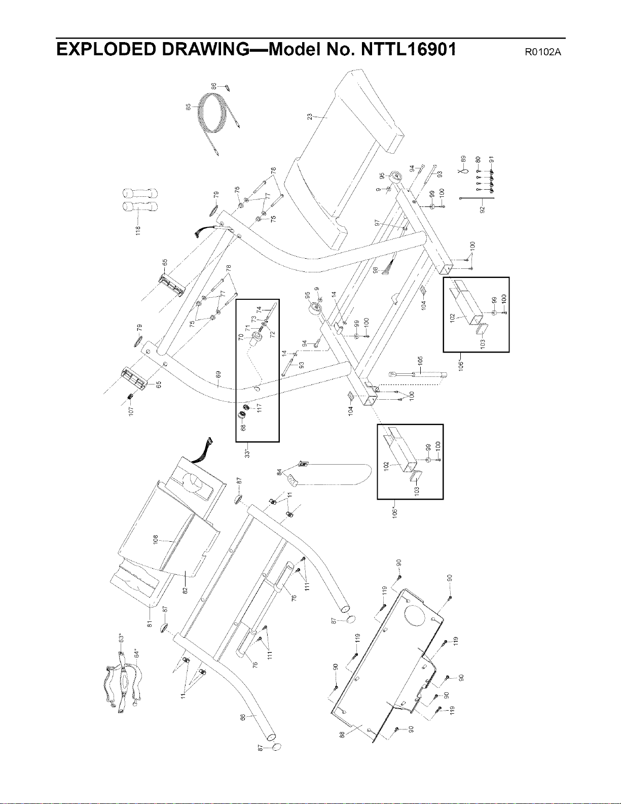
EXPLODED DRAWINGmModel No. NTTL16901
j_
R0102A
/
\ \
\ '\
/
/,o

LIMITED WARRANTY
WHAT IS COVERED--The entire NordicTrack ®SUMMIT 4500 treadmill ("Product") is warranted to be free of all defects
in material and workmanship.
WHO IS COVERED--The original purchaser or any person receiving the Product as a gift from the original purchaser.
HOW LONG IS IT COVERED--ICON Health & Fitness, Inc. ("ICON"), warrants the motor for three years after the date
of purchase. The belt and deck are covered for two years after the date of purchase. All mechanical components are
covered for two years after the date of purchase. All electrical components are covered for two years after the date of
purchase. Labor is covered for one year. The hood, covers, belly pan, and decals are covered for six months after the
date of purchase.
WHAT WE DO TO CORRECT COVERED DEFECTS--We will ship to you, without charge, any replacement part or
component, providing the repairs are authorized by ICON first and are performed by an ICON trained and authorized
service provider, or, at our option, we will replace the Product.
WHAT IS NOT COVERED--Any failures or damage caused by unauthorized service, misuse, accident, negligence, im-
proper assembly or installation, alterations, modifications without our written authorization or by failure on your part to
use, operate, and maintain as set out in your User's Manual ("Manual"). This warranty does not extend to products used
for commercial or rental purposes or to products used as store display modules.
WHAT YOU MUST DO--Always retain proof of purchase, such as your bill of sale; store, operate, and maintain the
Product as specified in the Manual; notify our Customer Service Department of any defect within 10 days after discov-
ery of the defect; as instructed, return any defected part for replacement or, if necessary, the entire product, for repair.
USER'S MANUAL--It is VERY IMPORTANT THAT YOU READ THE MANUAL before operating the Product.
Remember to do the periodic maintenance requirements specified in the Manual to assure proper operation and your
continued satisfaction.
HOW TO GET PARTS AND SERVICE--Simply call our Customer Service Department at 1-888-825-2588 and tell them
your name and address and the serial number of your Product. They will tell you how to get a part replaced, or if neces-
sary, arrange for service where your Product is located or advise you how to ship the Product for service. Before ship-
ping, always obtain a Return Authorization Number (RA No.) from our Customer Service Department; securely pack
your Product (save the original shipping carton if possible); put the RA No. on the outside of the carton and insure the
product. Include a letter explaining the product or problem and a copy of your proof of purchase if you believe the ser-
vice is covered by warranty.
ICON is not responsible or liable for indirect, special or consequential damages arising out of or in connection with the
use or performance of the product or damages with respect to any economic loss, loss of property, loss of revenues or
profits, loss of enjoyment or use, costs of removal, installation or other consequential damages of whatsoever nature.
Some states do not allow the exclusion or limitation of incidental or consequential damages. Accordingly, the above lim-
itation may not apply to you.
The warranty extended hereunder is in lieu of any and all other warranties and any implied warranties of merchantability
or fitness for a particular purpose is limited in its scope and duration to the terms set forth herein. Some states do not
allow limitations on how long an implied warranty lasts. Accordingly, the above limitation may not apply to you.
No one is authorized to change, modify or extend the terms of this limited warranty.
This warranty gives you specific legal rights and you may have other rights which vary from state to state.
ICON HEALTH & FITNESS, INC., 1500 S. 1000 W., LOGAN, UT 84321-9813
Part No. 174018 R0102A Printed in USA © 2002 ICON Health & Fitness, Inc.