Loading ...
Loading ...
Loading ...
5
Parts Needed
To order, see the “Assistance or Service” section of the Use and
Care Guide:
– Aluminum foil tape
Check local codes and consult gas supplier. Check existing
gas supply and electrical supply. See the appropriate “Electrical
Requirements” and “Gas Supply Requirements” sections.
It is recommended that all electrical connections be made by
a licensed, qualied electrical installer.
Optional Parts
To purchase these or any other accessories, please reference
the “Accessories” section of the Use and Care Guide for
contact information.
■Side Trim Kits:
5
⁄8" (1.7 cm) Black – Order Part Number W10675026
5
⁄8" (1.7 cm) Stainless Steel – Order Part Number
W10675028
1¹⁄8" (2.9 cm) Black – Order Part Number W10731886
1¹⁄8" (2.9 cm) Stainless Steel – Order Part Number
W10731887
■Backsplash Kits:
High 6" (15.2 cm) Black – Order Part Number W10655449
High 6" (15.2 cm) Stainless Steel – Order Part Number
W10655450
Location Requirements
IMPORTANT: Observe all governing codes and ordinances.
Do not obstruct ow of combustion and ventilation air.
■It is the installer’s responsibility to comply with installation
clearances specied on the model/serial/rating plate. The
model/serial/rating plate is located behind the oven door
on the top right-hand side of the oven frame.
■The range should be located for convenient use in the
kitchen.
■Recessed installations must provide complete enclosure
of the sides and rear of the range.
■To eliminate the risk of burns or re by reaching over the
heated surface units, cabinet storage space located above
the surface units should be avoided. If cabinet storage
is to be provided, the risk can be reduced by installing a
range hood or microwave hood combination that projects
horizontally a minimum of 5" (12.7 cm) beyond the bottom
of the cabinets.
■All openings in the wall or oor where range is to be
installed must be sealed.
■Cabinet opening dimensions that are shown must be used.
Given dimensions are minimum clearances.
■The anti-tip bracket must be installed. To install the
anti-tip bracket shipped with the range, see “Install
Anti-Tip Bracket” section.
■Grounded electrical supply is required. See the appropriate
“Electrical Requirements” section.
■Proper gas supply connection must be available. See “Gas
Supply Requirements” section.
■Contact a qualied oor covering installer to check that
the oor covering can withstand at least 200°F (93°C).
■Use an insulated pad or ¼" (0.64 cm) plywood under range
if installing range over carpeting.
IMPORTANT: To avoid damage to your cabinets, check
with your builder or cabinet supplier to make sure that the
materials used will not discolor, delaminate, or sustain other
damage. This oven has been designed in accordance with the
requirements of UL and CSA International and complies with
the maximum allowable wood cabinet temperatures of 194°F
(90°C).
Mobile Home – Additional Installation Requirements
The installation of this range must conform to the Manufactured
Home Construction and Safety Standard, Title 24 CFR,
Part 3280 (formerly the Federal Standard for Mobile Home
Construction and Safety, Title 24, HUD Part 280). When such
standard is not applicable, use the Standard for Manufactured
Home Installations, ANSI A225.1/NFPA 501A or with local
codes.
In Canada, the installation of this range must conform with the
current standards CAN/CSA-A240-latest edition or with local
codes.
Mobile Home Installations Require:
■When this range is installed in a mobile home, it must be
secured to the oor during transit. Any method of securing
the range is adequate as long as it conforms to the
standards listed above.
■Four-wire power supply cord or cable must be used in a
mobile home installation. The appliance wiring will need
to be revised. See “Electrical Requirements – U.S.A. Only”
section.
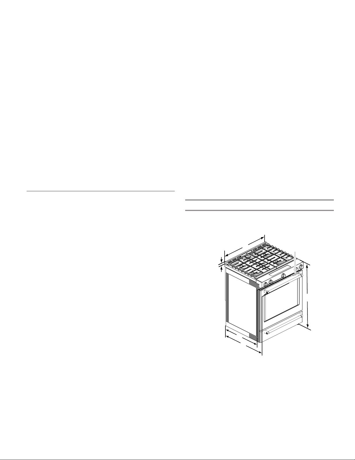
Product Dimensions
This manual covers several models. Your model may appear
different from the models depicted. Dimensions given are
maximum dimensions across all models.
B
D
A
F
E
C
A. 1³⁄16" (3.0 cm) height from
cooktop to top of vent
B. 29
7
⁄8" (75.9 cm)
C. Model/serial/rating plate
(located behind the oven door
on the top right-hand side of
the oven frame)
D. 36" (91.4 cm) height to top of
cooktop edge with leveling
legs screwed in all the way*
E. 28
5
⁄16" (71.9 cm) max. depth
from front of console to back
of range
F. 28
7
⁄8" (73.3 cm) max. depth
from handle to back of range
IMPORTANT: Range must be level after installation. Follow
the instructions in the “Level Range” section. Using the cooktop
as a reference for leveling the range is not recommended.
* Range can be raised approximately 1" (2.5 cm) by adjusting
the leveling legs.
Loading ...
Loading ...
Loading ...