Loading ...
Loading ...
Loading ...
14
Make Utility Connections
Make Gas Connection
WARNING
Explosion Hazard
Use a new CSA International approved gas supply line.
Install a shut-off valve.
Securely tighten all gas connections.
If connected to LP, have a qualified person make sure
gas pressure does not exceed 14" (36 cm) water
column.
Examples of a qualified person include:
licensed heating personnel,
authorized gas company personnel, and
authorized service personnel.
Failure to do so can result in death, explosion, or fire.
This range is factory-set for use with Natural gas. To use this
range with LP gas, see the “Gas Conversions” section before
connecting this range to the gas supply. Gas conversions from
Natural gas to LP gas or from LP gas to Natural gas must be
done by a qualied installer.
Typical Flexible Connection
1. Apply pipe-joint compound made for use with LP gas to
the smaller thread ends of the exible connector adapters.
See B and G in the following illustration.
2. Attach one adapter to the gas pressure regulator and
the other adapter to the gas shut-off valve. Tighten both
adapters, being certain not to move or turn the gas pressure
regulator.
3. Use a
15
⁄16" (2.4 cm) combination wrench and an adjustable
wrench to attach the exible connector to the adapters.
IMPORTANT: All connections must be wrench-tightened.
Do not make connections to the gas regulator too tight.
Making the connections too tight may crack the regulator
and cause a gas leak. Do not allow the regulator to turn
when tightening ttings.
A. ½" (1.3 cm) or ¾" (1.9 cm)
gas pipe
B. Use pipe-joint compound.
C. Adapter
D. Manual gas shut-off valve
E. Flexible connector
F. Adapter (must have ½"
[1.3 cm] male pipe thread)
G. Use pipe-joint compound.
H. Gas pressure regulator
ABC
EFG
D
H
Complete Connection
1. Open the manual shut-off valve in the gas supply line.
The valve is open when the handle is parallel to the gas pipe.
2. Test all connections by brushing on an approved
noncorrosive leak-detection solution. If bubbles appear,
a leak is indicated. Correct any leak found.
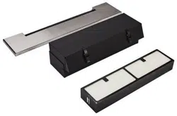
Connect Blower Assembly to Range
1. Remove the cardboard or hardboard from under the range.
2. Using 2 or more people, gently move the range into its nal
location.
3. Ensure the front edge of the Lower Filter Enclosure is above
the lower front frame cross support.
NOTE: If the Lower Filter Enclosure is below the Lower Front
Frame Cross Support, the blower may need to be shimmed.
4. Check to ensure the exible metal gas connector and
electrical cord are not kinked. Use a ashlight to look
underneath the bottom of and behind the range.
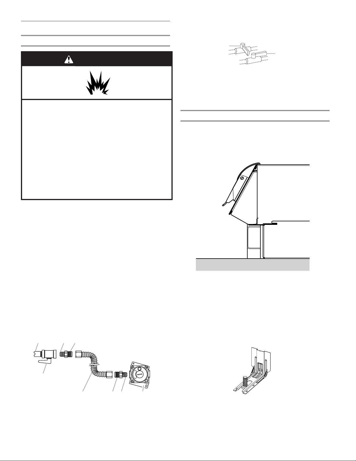
5. Verify that the anti-tip bracket is installed and engaged.
a. Use a ashlight to look underneath the bottom
of and behind the range.
b. Visually check that the rear range foot is inserted
into the slot of the anti-tip bracket.
A. Closed valve
B. Open valve
A
B
Loading ...
Loading ...
Loading ...