Loading ...
Loading ...
Loading ...
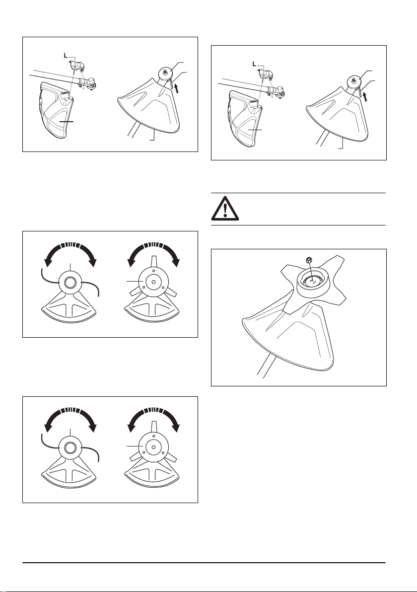
3. Attach with the bolt (L).
A
A
B
C
4. Install the drive disc (B) on the output shaft.
5. Turn the output shaft until one of the holes in the
drive disc aligns with the related hole in the gear
housing.
6. Put the locking pin (C) in the hole to lock the shaft.
7. Turn the trimmer head /plastic blades (H) in the
opposite direction from which the trimmer head/
plastic blades rotates.
H
H
To disassemble the cutting attachment
guard and trimmer head
1. Turn the trimmer head /plastic blades (H) in the
direction from which the trimmer head/plastic blades
rotates.
H
H
2. Pull the locking pin (C) out from the hole to unlock
the shaft.
3. Remove the drive disc (B) on the output shaft.
4. Loosen the bolt(L) from the cutting attachment
guard-fitting on the shaft.
A
A
B
C
5. Remove the cutting attachment guard (A).
To attach and remove the locknut
WARNING: Stop the engine, use protective
gloves and be careful around the sharp
edges of the cutting attachment.
A locknut is used to attach some types of cutting
attachments. The locknut has a left thread.
• To attach, tighten the lock nut in the opposite
direction to the direction of rotation of the cutting
attachment.
• To remove the locking nut, undo the lock nut in the
same direction as the cutting attachment rotates.
12
1363 - 001 - 25.10.2019
Loading ...
Loading ...
Loading ...