Loading ...
Loading ...
Loading ...
25
bromic.com/heat
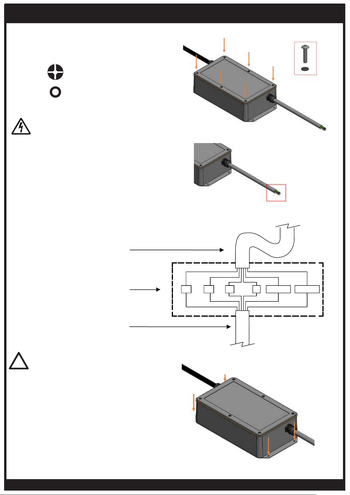
ELECTRICAL INSTALLATION – PENDANT HEATERS CONTROL
3. Refit cover to the box, ensuring the
6 X M3 O-Rings are present on the 6x Oval
head screws (#4-40 - Length: 1/2”).
5. Mount the Pendant Heater Control to
the desired ceiling or wall location using
appropriately sized and type screws (not
included) for the mounting surface.
Ensure the Pendant Heater Control is firmly
secured with fasteners in the 4 holes before
proceeding.
4. Wire the 6 Core Cable from the Eclipse
Control Box to the Corresponding coloured
wires on the 6 core cable from the Eclipse
Heater Head, according to local Electrical
Code regulations.
Ensure connection is adequately protected
from the environment using an IP54 (or
better) cover (not included) suitable for the
application.
The Power source MUST NOT be live when
installing the Eclipse Control Box.
DANGER
6x
#4-40 - Length: 1/2”
(Preassembled)
6x
M3 - O-Ring
(Preassembled)
IMPORTANT
The controller must be installed in a space
with free and open air flow which ensures
ambient temperature does not exceed 30°C.
!
Power cable from
controller (Supplied with
controller)
Junction box & terminals
(Provided by installer)
Power cable from heater
(Supplied with heater)
WHITE 24V DC
WHITE 24V DC
GREEN/YELLOW
GREEN/YELLOW
GREY 240V
GREY 240V
BLUE
BLUE
BLACK 240V
BLACK 240V
BROWN 24V DC
BROWN 24V DC
+24V DC
G
-24V DCL2 N
L1
Loading ...
Loading ...
Loading ...