Loading ...
Loading ...
Loading ...
INSTALLATION - 5191477A855/B
e
6. Refit the cover. Ensure the moulded part of
the glass (A) is facing the door.
7. Press the cover completely down so that it
attaches perfectly to the bulb support.
INSTALLATION
Gas connection
Connection to the gas mains can be made using
a continuous wall steel hose in compliance with
the guidelines established by the standards in
force. To use other types of gas, see the chapter
“Adaptation to different types of gas”. The
appliance's gas connector has a ½” external
thread (ISO 228-1).
Positioning
Depending on the type of installation, this
appliance belongs to classes:
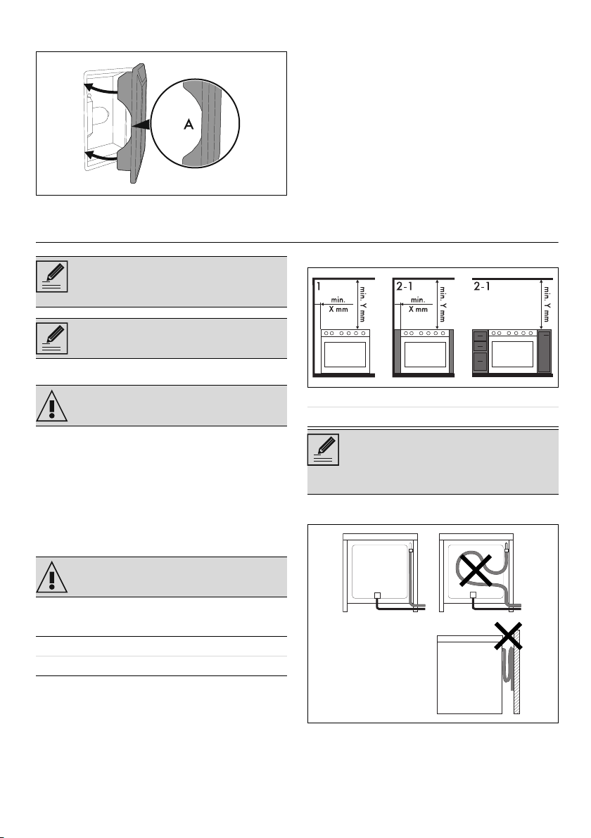
The appliance can be placed against walls that
are higher than the work surface, at a minimum
distance of X mm from the side of the appliance.
Any wall units installed above the appliance’s
worktop must be positioned at least Y mm from
it.
Connection with a rubber hose
Verify that all following conditions are met:
• The hose is attached to the hose connector
with safety clamps
• No part of the hose is in contact with hot
walls (max. 50 °C)
The appliance must be installed by a
qualified technician and according to
the regulations in force.
Appliance factory set for: natural gas
G20 at a pressure of 20 mbar.
See General safety instructions.
See General safety instructions.
Class 1 Free-standing
Class 2 - subclass 1 Built-in
X 150 mm
Y 750 mm
If a hood is installed above the
appliance, refer to the hood instructions
manual to make sure the correct
clearance is left.
üü
Loading ...
Loading ...
Loading ...