Loading ...
Loading ...
Loading ...
Installation of the X-Core should only be done by trained personnel.
1. Route valve wires between the control valve location and controller.
2. At valves, attach a common wire to either solenoid wire on all
valves. This is most commonly a white colored wire. Attach a
separate control wire to the remaining wire of each valve. All
wire connections should be done using waterproof connectors.
3. Route the valve wires through the conduit. Attach the conduit
through the bottom right side of the controller.
4. Secure the white valve common wire to the C (Common) screw
on the terminal strip. Attach each of the individual valve control
wires to the appropriate station terminals and tighten their
screws.
5. Indoor Models: route the transformer cable through the hole on
the le side of the controller and connect the wires to the two
screws marked 24 VAC.
Outdoor Models: transformer wires are already connected to the
AC terminals so all that is required is to connect primary power
to the junction box (see below).
NOTE: X-Core outdoor models are water and
weather-resistant throughout document. Connecting
the outdoor X-Core to primary AC power should only be
done by a licensed electrician following all local codes.
Improper installation could result in shock or re hazard.
High Voltage Wiring (Outdoor Model only)
1. Route AC power cable and conduit through the ½" (13 mm)
conduit opening on the le side bottom of the cabinet.
2. Connect one wire to each of the two wires inside the junction
box. The ground wire should be connected to the green wire.
Wire nuts are provided to make these connections.
Note: For –E models only: Connect the wires to the AC
terminal block inside the junction box. AC supply wires must
be 14 AWG (1.85 mm) or larger with appropriate circuit breaker
for the wire size. A switch or circuit-breaker shall be included
in the building installation (in close proximity to the controller,
within easy reach of the operator) and marked as the discon-
necting device for the equipment.
3. Replace the junction box cover.
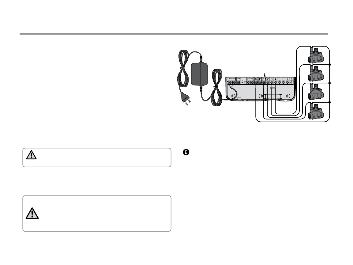
Valve Common Wire
CONNECTING VALVES AND TRANSFORMER
BAT
Connect the two transformer
wires to the two AC Terminals
Valve 4
Valve 3
Valve 2
Valve 1
Valve
Wires
NOTE: The indoor transformer cable should not be cut.
If the cable is cut, the red and white wires in the cable
must be joined together, or the controller will not work.
9
Loading ...
Loading ...
Loading ...