Loading ...
Loading ...
Loading ...
4 ■English
Choosing an Installation Site
2. Wireless remote controller
•Turnonalltheuorescentlampsintheroom,ifany,andndthesitewhereremotecontrollersignalsareproperly
receivedbytheindoorunit(within13ft(4m)).
3. Outdoor unit
•Foroutdoorunitinstallation,seetheinstallationmanualsuppliedwiththeoutdoorunit.
Preparations before Installation
■
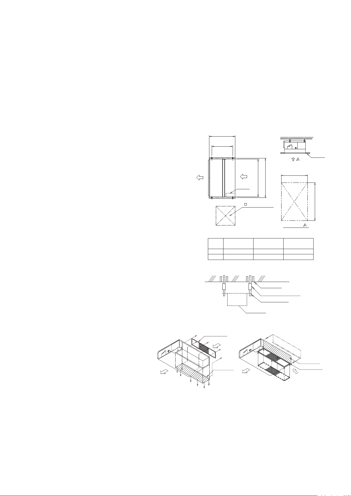
Relation of the unit to the suspension bolt positions.
•Installtheinspectionopeningonthecontrolboxsidewhere
maintenanceandinspectionofthecontrolboxareeasy.Install
theinspectionopeningalsointhelowerpartoftheunit.
■
Make sure the range of the unit’s external static
pressure is not exceeded.
(Seethetechnicaldocumentationfortherangeoftheexternal
staticpressuresetting.)
■
Open the installation hole. (Pre-set ceilings)
•Oncetheinstallationholeisopenedintheceilingwheretheunit
istobeinstalled,passrefrigerantpiping,drainpiping,
transmissionwiring,andremotecontrollerwiring(unneededif
usingawirelessremotecontroller)totheunit’spipingandwiring
holes.See“Refrigerant Piping Work”,“Drain Piping Work”,
and“Wiring”.
•Afteropeningtheceilinghole,makesureceilingislevelif
needed.Itmightbenecessarytoreinforcetheceilingframeto
preventshaking.Consultanarchitectorcarpenterfordetails.
■
Install the suspension bolts.
(UseW3/8toM10suspensionbolts.)
•Useahole-in-anchor,sunkeninsert,sunkenanchorforexisting
ceilings,andasunkeninsert,sunkenanchororotherparttobe
procuredintheeldtoreinforcetheceilingtobearingtheweight
oftheunit.(RefertoFig.)
19-11/16 (500)
17-3/4 (450)
(Inspection opening
size)
Air outlet
Suspension
bolt pitch
(unit : in (mm))
Air inlet
Control
box
(Suspension bolt pitch)
Ceiling
24-7/16 (620)
24-7/16 (620)
A
Arrow view
Inspection door
(Ceiling opening)
<SERVICE SPACE>
A
B
FDXS09/12
CDXS07
CDXS15/18
A
27-9/16 (700)
B
29-1/8 (740) 37 (940)
35-7/16 (900)
CDXS24
44-7/8 (1140)
43-5/16 (1000)
Note: All the above parts are field supplied.
Suspension bolt
Long nut or turn-buckle
Anchor bolt
Indoor unit
Ceiling slab
■
Mount chamber cover and air lter
(accessory).
Forbottomintake,replacethechambercoverandthe
protectionnetintheprocedurelistedinFig.
(1)Removetheprotectionnet.(6locations)
Removethechambercover.(7locations)
(2)Reattachtheremovedchambercoverinthe
orientationshowninFig.(7locations)
Reattachtheremovedprotectionnetinthe
orientationshowninFig.(6locations)
RefertoFig.forthedirectionoftheprotectionnet.
Air inlet
Air inlet
(1)
Chamber
cover
(2)
Air outlet
Air outlet
Chamber
cover
Protection net
Protection net
01_EN_3P297301-4D.indd 4 5/8/2017 5:10:21 PM
Loading ...
Loading ...
Loading ...