
Owner's Manual
iI:RRFTSMAN°I
20 HP
ELECTRIC START
48" MOWER
6 SPEED TRANSAXLE
LAWN TRACTOR
Model No.
917.272232
• Safety
• Assembly
• Operation
• Maintenance
• Repair Parts
CAUTION:
Read and fellow all
Safety Rules and Instructions
before operating this equip-
ment.
For answers to your questions
about this product, Call:
1-800-659-5917
Sears Craftsman Help Line
5 am - 5 pm, Mort - Sat
Sears, Roebuck and Co., Hoffman Estates, IL 60179
Visit our Ctaflsman website: wwwsears corn/craftsman
............................................... 2
Safety Rules ......................................... 3
Product Specifications .......................... 6
Assembly .............................................. 8
Operation ............................................ 13
Maintenance Schedule ...................... 19
19
Service and Adjustments .................... 23
Storage ............................................... 29
Troubleshooting ................................. 30
Repair Parts ........................................ 34
Parts Ordering ..................... Back Cover
LIMITED TWO YEAR WARRANTY ON CRAFTSMAN RIDING EQUIPMENT PARTS
For two (2) years from the date of purchase, if this Craftsman Riding Equipment is
maintained, lubricated and tuned up according to the instructions in the owner's
manual, Sears will repair or replace, free of charge, any parts found to be defective in
material or workmanship. Warranty service is available free of charge by returning your
Craftsman riding equipment to your nearest Sears Service Center. In-home warranty
service is available but a trip charge will apply. This warranty applies only while this
product is in the United States.
This Warranty does not cover:
• Expendable items which become worn during normal use, such as blades, spark
plugs, air cleaners, belts and oilfilters.
• Tire replacement or repair caused by punctures from outside objects, such as nails,
thorns, stumps, or glass.
• Repairs necessary because of operator abuse, including but not limitedto, damage
caused by towing objects beyond the capability of the riding equipment, impacting
objects that bend the frame or crankshaft, or over speeding the engine.
• Repairs necessary because of operator negligence, including but not limitedto,
electrical and mechanical damage caused by improper storage, failure to use the
proper grade and amount of engine oil, failure to keep the deck clear of flammable
debris, or the failure to maintain the equipment according to the instructions con-
tained in the owner's manual.
• Engine (fuel system) cleaning or repairs caused by fuel determined to be contami-
nated or oxidized (stale). In general, fuel should be used within thirty (30) days of its
purchase date.
• Riding equipment used for commercial or rental purposes. A product is =used for
commercial purpose" if is used for any purpose other than single family household
dwellings or in usage where profit is made.
LIMITED 90 DAYWARRANTY ON BATTERY
For ninety (90) days from date of purchase, if any battery included with this riding
equipment proves defective in material or workmanship and our testing determines the
batterywill not hold a charge, Sears will replace the battery at no charge. Warranty
service is available free of charge by returning your Craftsman dding equipmentto
your nearest Sears Service Center. In-home warranty service is available but a trip
charge will apply. This warranty applies only while this product is in the United States.
TO LOCATE THE NEAREST SEARS SERVICE CENTER OR TO SCHEDULE IN-HOME
WARRANTY SERVICE, SIMPLY CONTACT SEARS AT 1-800-4-MY-HOME
This Warranty gives you specific legal rights,and you may also have other rights which
may vary from state to state.
Sears, Roebuck and Co., D/817 WA, Hoffman Estates, IL 60179
|MPORTANT: This cuttk_gmachine is capable of amputating hands and feet and,
throwing objects. Failure to observe the following safety instructions could resultm
seriousinjury or death.
I. GENERAL OPERATION
• Read, understand, and follow all
instructionsin the manual and on the
machine before starting,
• Only allow responsible adults, who are
familiar with the instructions,to operate
the machine.
• Clear the area of objects such as
rocks,toys wire etc., which could be
picked up and thrown by the bade.
• Be sure the area is clear of other
people before mowing. Stop machine
if anyone enters the area.
Never carry passengers.
Do not mow in reverse unless abso-
lutely necessary, Always look down
and behind before and while backing.
• Be aware of the mower discharge
directionand do not pointit at anyone.
Do not operate the mower without
either the entire grass catcher or the
guard in place.
• Slow down before turning.
• Never leave a running machine
unattended. Alwaysturn off blades, set
parking brake stop engine, and
remove keys before dismounting.
• Turn off blades when not mowing.
• Stop engine before removing grass
catcher or unclogging chute.
• Mow on|y in daylight or good artificial
light.
• Do not operate the machine while
under the ir_tuence ol alcohol or drags.
• Watch for traffic when operating near or
crossing roadways.
• Use extracarewhm'_loadingor
unloading the machine into a trailer or
truck.
• Data indicatesthat operators, ego 60
years and above, are involved in a
large percentage of riding mawer-
r_ated injuries. These operators
should evaluate their ability to operate
the ridingmower safely enough to
protect themselves and others from
serious injury.
• Keep machine free of grass, leaves or
other debris balld-up which can touch
hot exhaust / engine parts and bum.
Do not allow the mower deck to plow
leaves or other debds which can cause
build-upto occur. Clean any oil or fuel
spilla_]ebefore operating or storingthe
machine. Allow machine to cool before
storage.
11.SLOPE OPERATION
Slopes are a majorfactor related to less-of-
control and tipover accidents, which can
result in severe in ury or death. All slopes
require extra caut on. Ifyoucannot back up
the slope or if youfeel uneasy on it, do not
mow it.
DO:
• Mow up and down slopes, not across.
• Remove obstacles such as rocks,tree
limbs, etc.
• Watch forholes, ruts, or bumps.
Uneven terrain could overturn the
machine. Tallgrass can hide ob-
stacles.
• Use slow speed. Choose a low gear
so that you will not have to stop or shift
while on the slope,
• Follow the manufacturer's recommen-
dationsfor wheel weights or counter-
weights to improve stability.
• Use extra care with grass catchers or
other attachments. These can change
the stabilityof the machine.
• Keep all movement on the slopes s/ow
and gradual. Do not make sudden
changes in speed or direction.
• Avoid starting or stopping on a _Jope. If
tires lose traction, disengage the
blades and proceed slowly straight
down the slope.
DO NOT:
• Do not turn on slopes unless neceso
sary, and then, turn slowlyam:l gradu-
ally downhill, if possible.
• Do not mow near drop-offs, ditches, or
embankments. The mower could
suddenly turn over if a whee_ is over
the edge of a cliff or ditch, or if an edge
caves in.
• Do not mow on wet grass. Reduced
traction could cause sliding.
• Do not try to stabilizethe machine by
putting your foot on the ground,
• Do not use grass catcher on steep
slopes.
|11.CHILDREN
Tragicaccidents can occur ff the operator
is not alert to the presence ofchildren.
Childrenare often attracted to the
machine and the mowing activity. Never
assume that children will remain where
you last saw them.
• Keep children out of the mowing area
and under the watchful care of another
responsible adult.
• Be alert and turnmachine off il children
enter the area.
• Before and when backing, look behind
and down for small children.
• Never carry children. They may fall off
and be seriously injured or interfere
with safe machine operation.
• Never allow childrento operate the
machine.
• Use extra care when approaching blind
corners, shrubs, trees, or other objects
that may obscure vision.
IV, SERVICE
• Use extra care in handling gasoline
and other fuels. They are flammable
and vapors are explosive.
-Use only an approved container.
-Never remove gas cap or add fuel
with the engine running. Allow
engine to cool before refueling. Do
notsmoke.
- Never refuel the machine indoors.
- Never storethe machine or fuel
container inside where there is an
open flame, such as a water heater.
• Never run a machine inside a closed
area.
• Keep nuts and bolts, especially blade
attachment bolts, tight and keep
equipment in good condition.
• Never tamper with safety devices.
Check their proper operation regularly.
• Keep machine free of grass, leaves, or
other debris build-up. Clean oil or fuel
spillage. Allow machine to cool before
storing.
• Stop and inspect the equipment "ityou
stdke an object. Repair, if necessary,
before restarting.
• Never make adiustments or repairs
with the engine running.
• Grass catcher components are subject
to wear, damage, and deterioration,
which could expose moving parts or
allow objects to be thrown. Frequently
check components and replace with
manufacturer's recommended parts,
when necessary.
• Mower blades are sharp and can cut.
Wrap the blade(s) or wear gloves, and
use extra caution when servicing them.
• Check brake operation frequently.
Adjust and service as required.
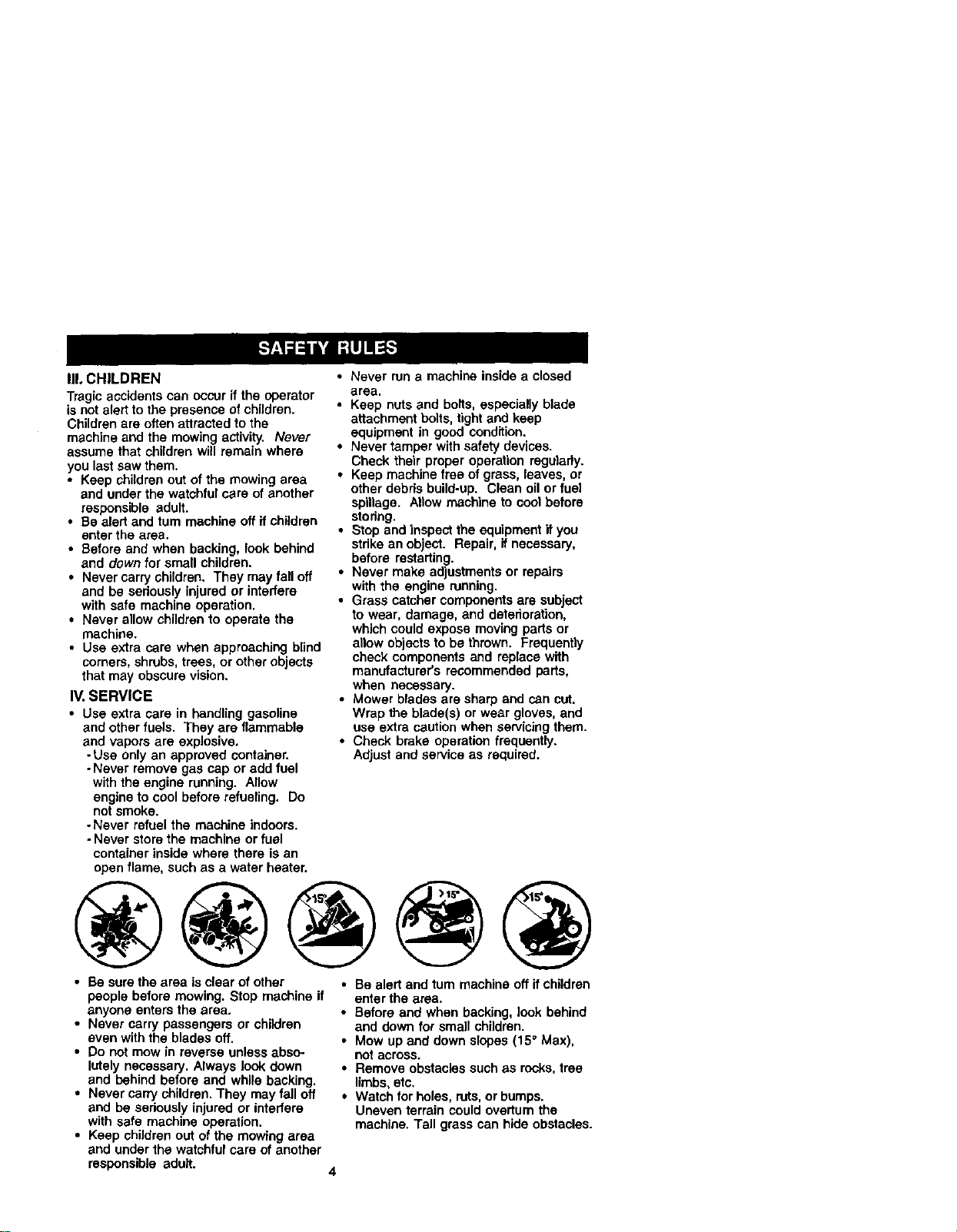
• Be sure the area is clear of other
people before mowing. Stop machine if
anyone enters the area.
• Never carry passengers or children
even with the blades off.
• Do not mow in reverse unless abso-
Ictely necessary. Always look down
and behind before and while backing.
• Never carry children. "]'hey may fall off
and be seriously Injured or interfere
with safe machine operation.
• Keep children out of the mowing area
and under the watchful care of another
• Be alert and turn machine off if children
enter the area.
• Before and when backing, look behind
and down for small children.
• Mow up and down slopes (15° Max),
not across.
• Remove obstacles such as rocks,tree
limbs, etc.
• Watch for holes, ruts,orbumps.
Uneven terrain could overturn the
machine. Tall grass can hide obstacles.
responsible adult.
4

• Useslow speed. Choose a low gear so
that you will not have to stop or shift
whUe on the slope.
• Avoid starting or stopping on a slope. If
tires lose traction, disengage the
blades and proceed slowly straight
down the slope.
• If machine stops while going uphill,
disengage blades, shift into reverse
and back down slowly.
• Do not turn on slopes unless neces-
sary, and then, turn slowly and gradu-
ally downhill, if possible.
,J_Look for this symbol to point out
importantsafety precautions. Itmeans
CAUTIONIX! BECOMEALERTI!I YOUR
SAFETY IS INVOLVED.
,ACAUTION: In order to prevent acciden-
tal starting when setting up, transporting,
adjusting or making repairs, always
disconnect spark plug wire and place
wire where it cannot contact spark plug.
_'I_CAUTION: Do not coast down a hill in
neutral, you may lose control ofthe
tractor.
ACAUTION: Tow only the attachments
that are recommended by and comply
with specificationsof the manufacturer of
your tractor. Use common sense when
towing. Operate only at the lowest
possible speed when on a slope. Too
heavy of a load, while on a slope, is
dangerous. Tires can lose tractionwith
the ground and cause you to lose control
of your tractor.
4(_WARNING: Engine exhaust, some of its
constituents, and certain vehicle compo-
nents contain or emit chemicals known to
the State of California to cause cancer
and birth defects or other reproductive
harm.
A,WARNING: Battery posts terminals and
related accassodes contain lead and ead
compounds, chemicals known to the State
of California to cause cancer and birth
defects or other reproductiveharm. Wash
hands after handling.
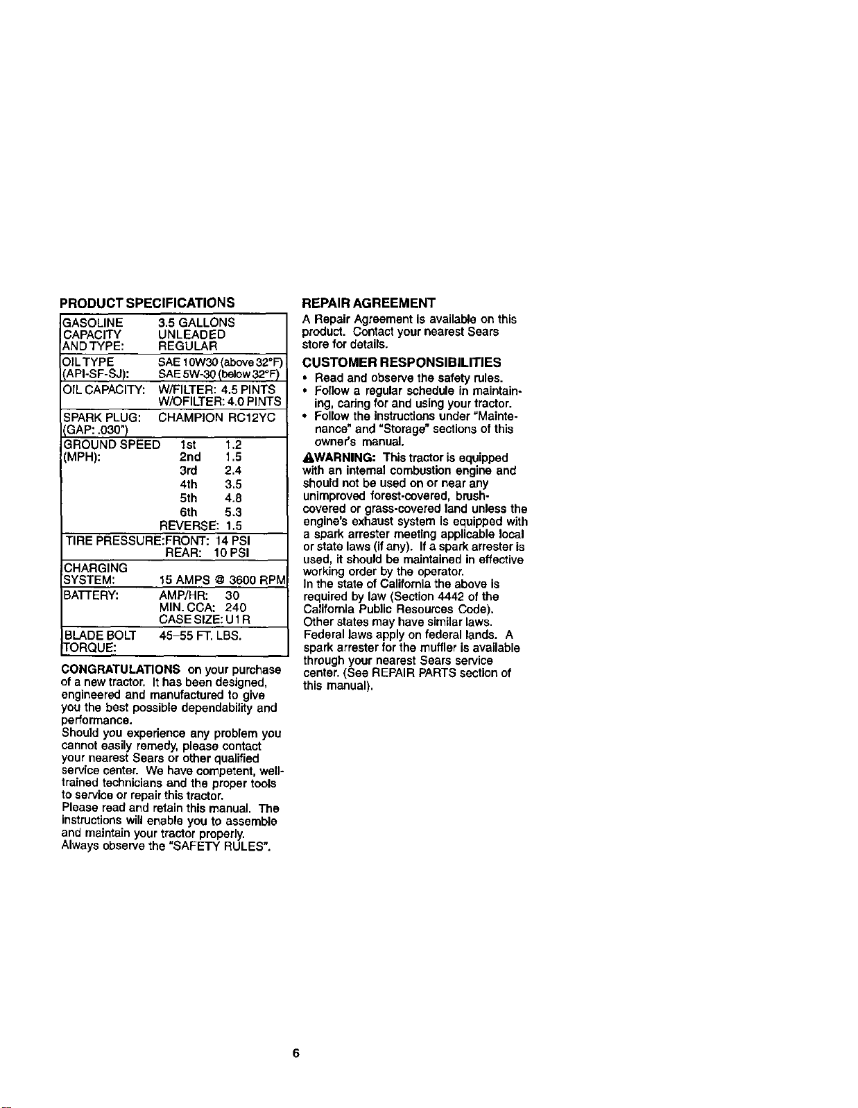
PRODUCTSPECIFICATIONS
3ASOLINE 3.5GALLONS
CAPACITY UNLEADED
_,NDTYPE: REGULAR
:)ILTYPE SAE 10W30(above32°F)
_API-SF-SJ): SAE5W-30 Ibelow32°F)
OIL CAPACITY: W/FILTER: 4.5 PINTS
W/OFILTER: 4.0 PINTS
SPARK PLUG: CHAMPION RC12YC
3AP: .030")
GROUND SPEED 1st 1.2
(MPH): 2nd 1.5
3rd 2.4
4th 3.5
5th 4.8
6th 5.3
REVERSE: 1.5
TIRE PRESSURE:FRONT: 14 PSI
REAR: 10 PSI
CHARGING
SYSTEM: 15 AMPS @ 3600 RPIV
BATTERY: AMP/HR: 30
MIN. CCA: 240
CASE SIZE: U1R
BLADE BOLT 45-55 FT. LBS.
TORQUE:
CONGRATULATIONS on your purchase
of a new tractor. It has been designed,
engineered and manufactured to give
you the best possible dependability and
performance.
Should you experience any problem you
cannot easily remedy, please contact
your nearest Sears or other qualified
service center. We have competent, well-
trained technicians and the proper tools
to service or repair this tractor.
Please read and retain this manual. The
instructionswill enable youto assemble
and maintain yourtractor properly.
Always observethe "SAFETY RULES".
REPAIR AGREEMENT
A Repair Agreement is available on this
product. Contact your nearest Sears
store for details.
CUSTOMER RESPONSIBILITIES
• Read and observe the safety rules.
• Follow a regular schedule in maintain-
ing, cadng for and using your tractor.
• Follow the instructionsunder =Mainte-
nance"and "Storage" sections of this
owner's manual.
_I_WARNING: This tractor is equipped
with an internal combustion engine and
should not be used on or near any
unimproved forest-covered, brush-
covered or grass-covered land unless the
engine's exhaust system is equipped with
a spark arrester meeting applicable local
or state laws (ifany). If a spark arrester is
used, it should be maintained in effective
working order by the operator.
In the state ofCalitomia the above is
required by law (Section 4442 of the
California Public Resources Code).
Other states may have similarlaws.
Federal laws apply on federal lands. A
spark arrester for the muffler is available
through your nearest Sears service
center. (See REPAIR PARTS section of
this manual).
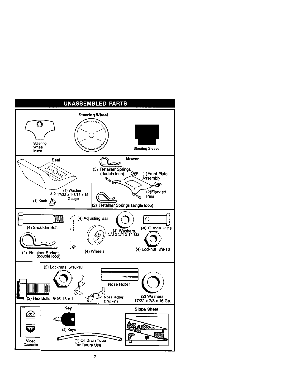
Steering Wheel
Steering
Wheel
Insert
Steedng Sleeve
_her
17/32x1-3/16x 12
(1) Knob_ Gauge
Mower
(5) Retainer Spdngs
(double loop) - _P (1)Front Plate
_ ,_ s
(2) Retainer Springs(single loop)
_ f (4) AdjustingBar
@
(4) Shoulder Bolt _
(4) Retainer Spdngs (4) Wheels
(double loop)
(4) Locknut 3/8-16
(2) Locknuts 5/16-18
I IIIIIIIIIIIIIIIIHII,H]_ _._, Nose Roller
IF ',2)Hex Bolts 5/16-18 x, _ Nr°ScekRs°ller (2) Washers
t7/32 x 7/8 x 16 Ga.
Key Slope Sheet
Cassette For FutureUse
7
Your new tractor has been assembled at the factory wffhexception of those parts left
unassembled for shipping purposes. To ensure safe and proper operation of your
tractor all parts and hardware you assemble must be tightened securely. Use the
correct tools as necessary to insure proper tightness. Review the video cassette before
you begin.
TOOLS REQUIRED FOR ASSEMBLY
A socket wrench set will make assembly
easier. Standard wrench sizes you need
are listed below.
(1) 9/16" Wrench (1) 3/4" Socket w/
(1) 1/2" wrench drive ratchet
(1) Utilityknife (1) Pliers
(1) Tire pressure gauge
When rightor left hand is mentioned in
this manual, it means, from your pointof
view,when you are in the operating
position (seated behind the steering
wheel).
TO REMOVETRACTOR FROM
CARTON
UNPACK CARTON
1. Remove all accessible loose parts
and parts boxes from shipping carton.
2. Cut, from top to bottom, along lines on
all four comers of shipping carton, and
lay panels flat.
3. Remove mower and package materi-
als.
4. Check for any additional loose parts
or boxes and remove.
BEFORE REMOVING TRACTOR
FROM SKID
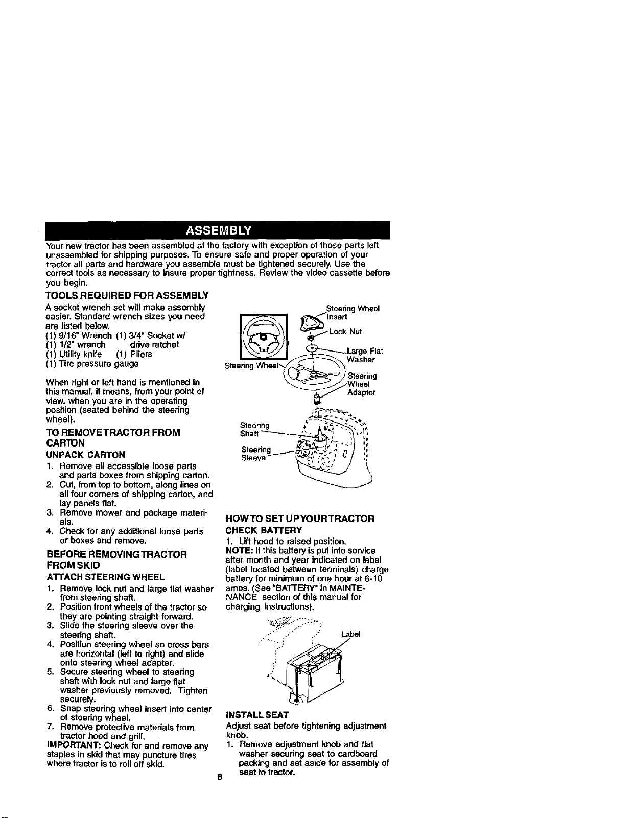
AI"I'ACH STEERING WHEEL
1. Remove lock nut and large flat washer
from steering shaft.
2. Positionfront wheels of the tractor so
they are pointing straight forward.
3. Slide the steering sleeve over the
steering shaft.
4, Position steering wheel so cress bars
are horizontal (left to right) and slide
onto steering wheel adapter.
5. Secure steering wheel to steering
shaft with lock nut and large flat
washer previously removed. Tighten
securely.
6. Snap steering wheel insert intocenter
of steering wheel.
7. Remove protective materials from
tractor hood and grill.
IMPORTANT: Check for and remove any
staplesin skidthat may puncture tires
where tractor isto roll off skid.
HOWTO SET UPYOURTRACTOR
CHECK BA'n'ERY
I. Lift hood to raised position.
NOTE: If thisbattery isput intoservice
after month and year indicated on label
(label located between terminals) charge
batteryfor minimumof one hour at 6-10
amps. (See "BA'I-I'ERY" in MAINTE-
NANCE section of this manual for
charging instructions).
INSTALL SEAT
Adjust seat before tightening adjustment
knob.
1. Remove adjustment knob and flat
washer securing seat to cardboard
packing and set aside for assembly of
8 seat to tractor.
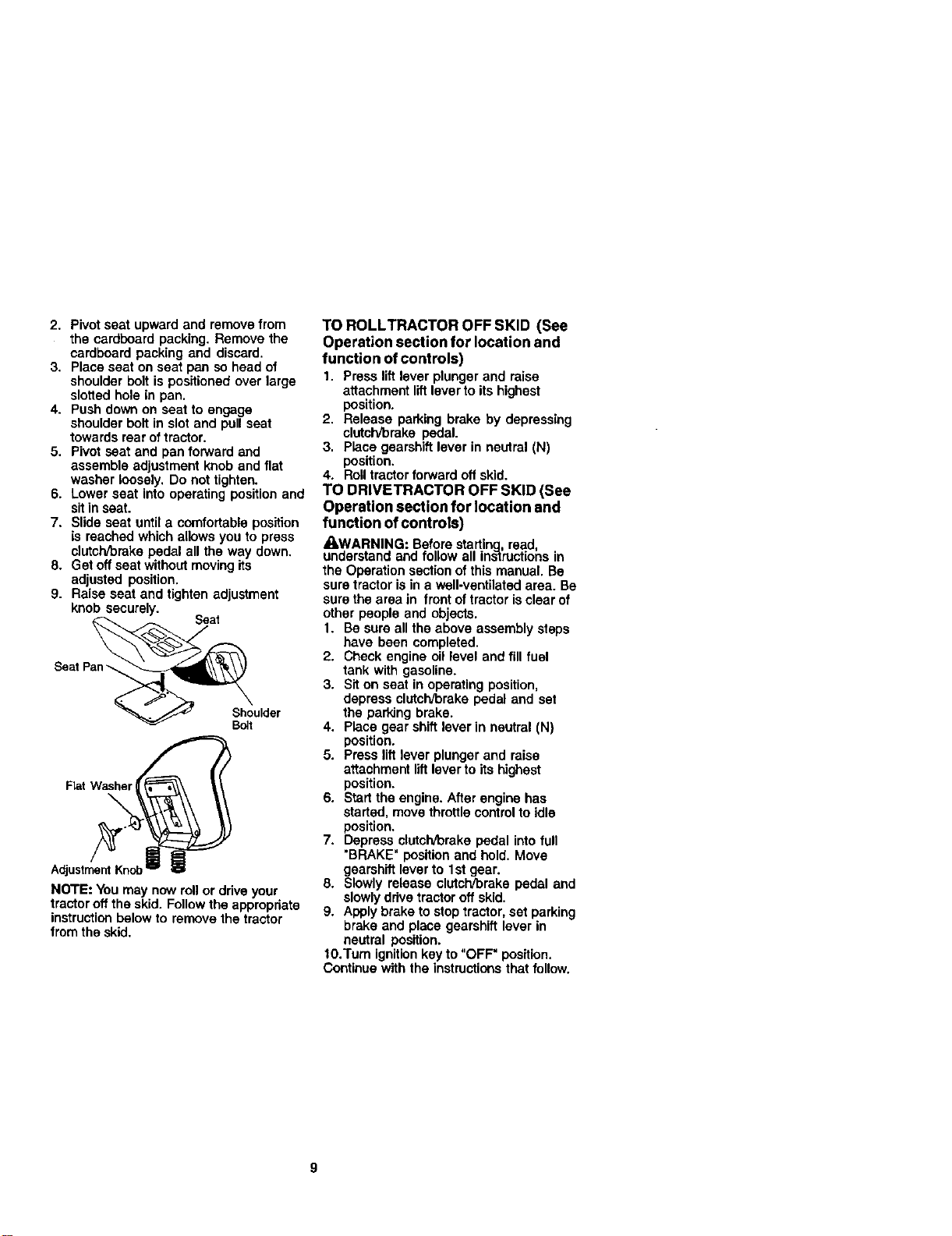
2. Pivot seat upward and remove from
the cardboard packing. Remove the
cardboard packing and discard.
3. Place seat on seat pan so head of
shoulder bolt is positioned over large
slotted hole in pan.
4. Push down on seat to engage
shoulder bolt in slot and pull seat
towards rear of tractor.
5. Pivot seat and pan forward and
assemble adjustment knob and flat
washer loosely. Do not tighten.
6. Lower seat into operating position and
sit in seat.
7. Slide seat until a comfortable position
is reached which allows you to press
clutch/brake pedal all the way down.
8. Get off seat without moving its
adjusted position.
9. Raise seat and tighten adjustment
knob securely.
Seat
Seat Pan'--.
Shoulder
Bolt
FlatWasher
NOTE: You may now roll or drive your
tractor oft the skid. Followthe appropriate
instructionbelow to remove the tractor
from the skid.
TO ROLLTRACTOR OFF SKID (See
Operation section for location and
function of controls)
1. Press lift lever plunger and raise
attachment liftlever to its highest
position.
2. Release parking brake by depressing
clutch/brake pedal.
3. Place gearshift lever in neutral (N)
position.
4. Roll tractor forward off skid.
TO DFIIVETRACTOR OFF SKID (See
Operation section for location and
function of controls)
AWARNING; Before startinchread,
understand and follow all instructionsin
the Operation sectionof this manual. Be
sure tractor isin a well-ventilated area. Be
sure the area in front of tractor isclear of
other people and objects.
1. Be sure all the above assembly steps
have been completed.
2. Check engine oil level and fill fuel
tank with gasoline.
3. Sit on seat in operating position,
depress clutch/brake pedal and set
the parking brake.
4. Place gear shift lever in neutral (N)
position.
5. Press liftlever plunger and raise
attachment lift lever to its highest
position.
6. Start the engine. After engine has
started, move throttle controlto idle
position.
7. Depress clutch/brake pedal into full
"BRAKE" position and hold. Move
gearshift lever to 1st gear.
8. Slowly release clutch/brake pedal and
slowly drive tractor off skid.
9. Apply brake to stop tractor, set parking
brake and place gearshift lever in
neutral position.
t0.Tum ignitionkey to "OFF" position.
Continue with the instructionsthat follow.
ASSEMBLE GAUGEWHEELSTO
MOWER DECK
The gauge wheels are designed to keep
the mower deck in proper positionwhen
operatingmower. Be sure they are
properly adjusted to ensure optimum
mower performance.
1. Slide gauge wheel bar down into
bracket channel, Be sure that gauge
wheel bar aligning holes are on top.
Assemble gauge wheels as shown
using shoulder bolts,3/8 washers and
3/8-16 center Iocknuts and tighten
securely.
2. For ease of mower totraCtorassem-
bly raise gauge wheels to highest
position and retain with clevis pns
and spring retainers.
NOTE: Adjust gauge wheels before
operatingmower. See "TO ADJUST
GAUGE WHEELS" in the Operation
sectionof this manual.
Gauge
3/8
Locknut
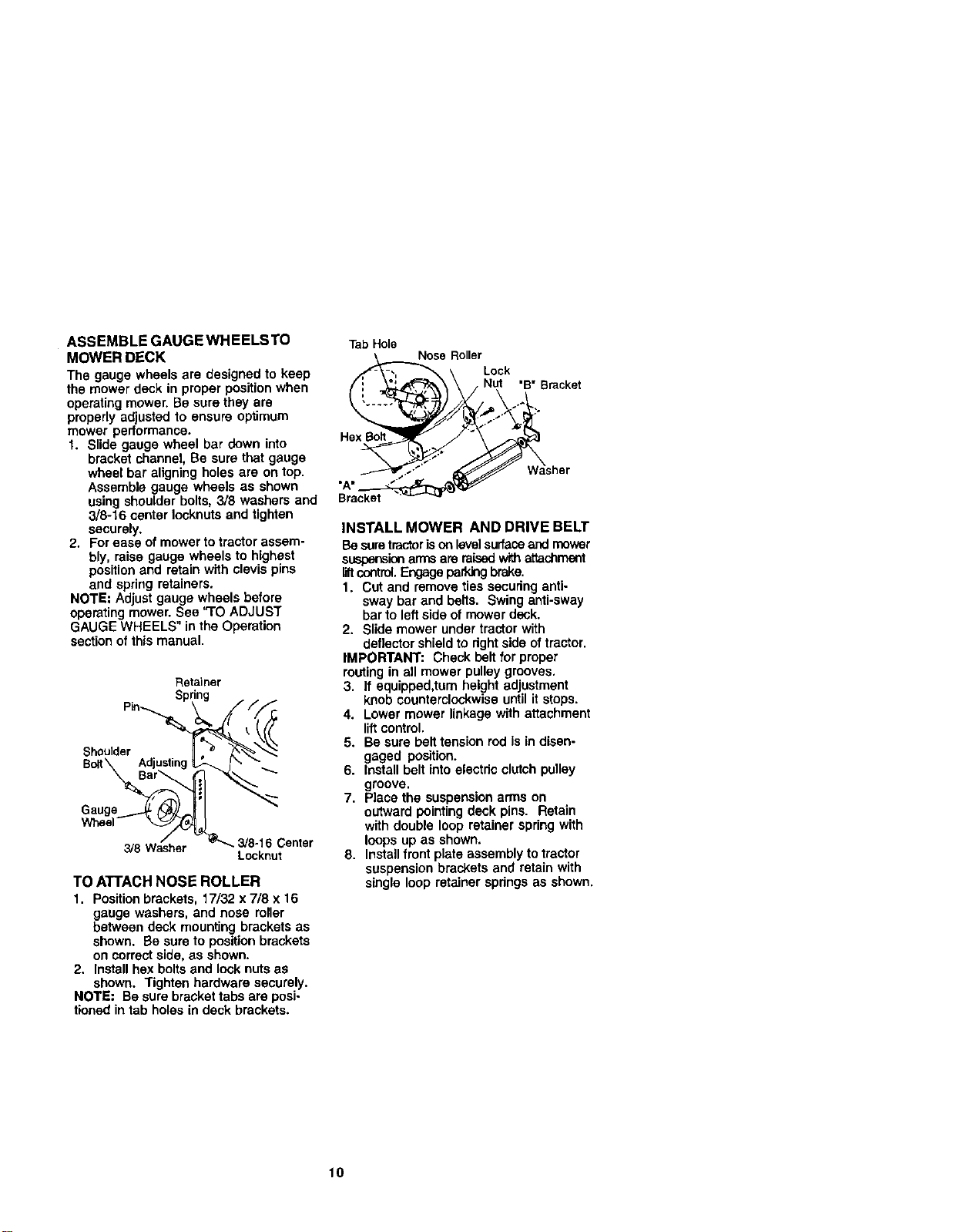
TO ATTACH NOSE ROLLER
1. Positionbrackets, 17/32 x 7/8 x 16
gauge washers, and nose roller
between deck mounting brackets as
shown. Be sure to position brackets
on correct side, as shown.
2. Install hex bolts and lock nuts as
shown. Tighten hardware securely.
NOTE: Be sure bracket tabs are posi-
tioned in tab holes in deck brackets.
TabHole
Nose Roller
ut "B" Bracket
Hex_
Washer
Bracket ,_ _.w
INSTALL MOWER AND DRIVE BELT
Be suretractorisonlevelsurfaceand mower
suspensionarms are raisedwith attachment
liftcontrol.Engage parkingbrake.
1. Cut and remove ties securing anti-
sway bar and belts. Swing anti-sway
barto leftside of mower deck.
2. Slide mower under tractor with
deflector shield to dght side oftractor.
IMPORTANT; Check belt for proper
routing in all mower pulley grooves,
3. If equipped,turn height adjustment
knob counterclockwise until it stops.
4. Lower mower linkage with attachment
liftcontrol.
5. Be sure belt tension rod is in disen-
gaged position.
6. Install belt into electdc clutch pulley
groove.
7. Place the suspension arms on
outward pointing deck pins. Retain
with double loop retainer spring with
loops up as shown.
8. Installfront plate assembly to tractor
suspension brackets and retain with
single loop retainer spdngs as shown.
10
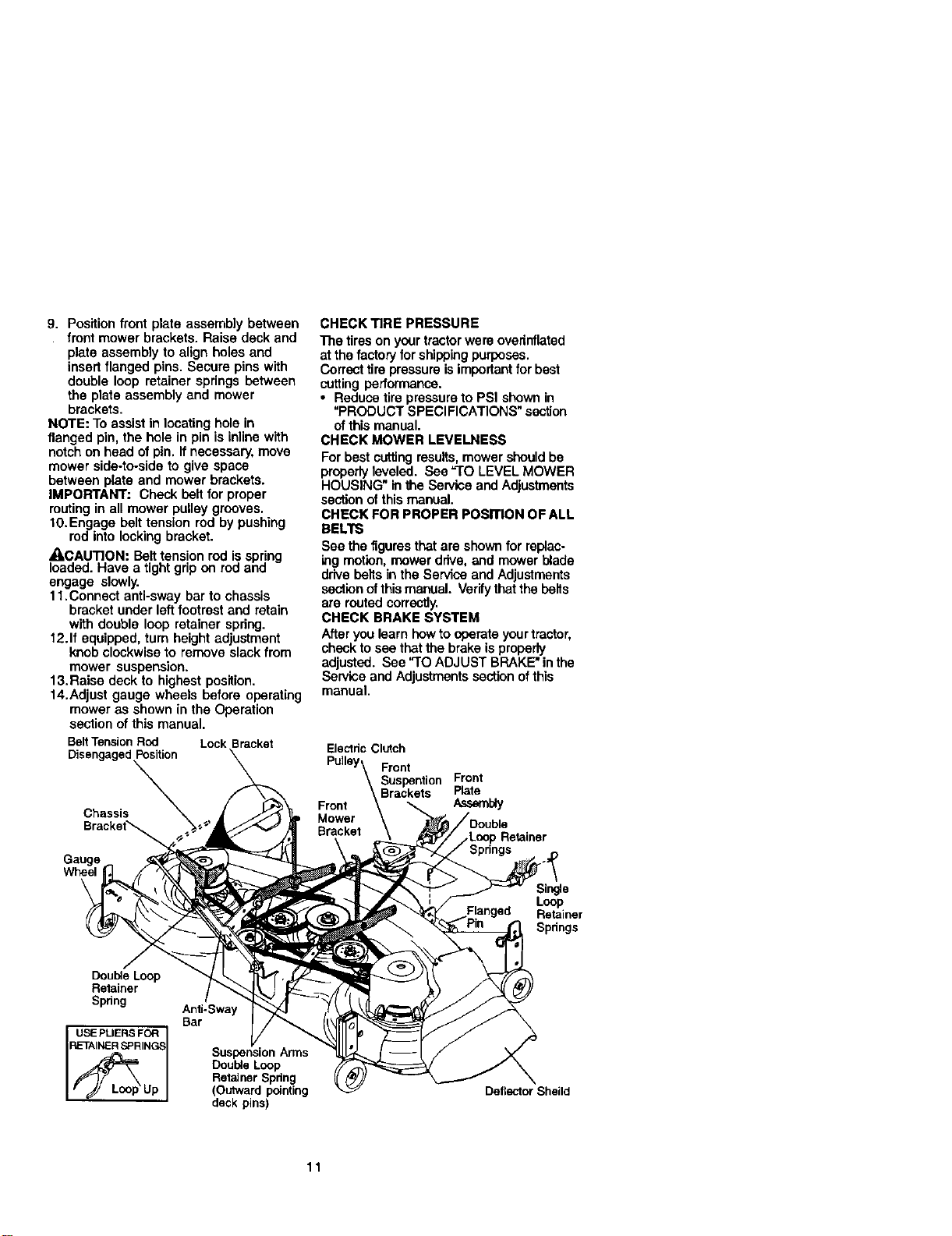
9. Positionfrontplateassemblybetween
front mower brackets. Raise deck and
plate assembly to align holes and
insert flanged pins. Secure pins with
double loop retainer springs between
the plate assembly and mower
brackets.
NOTE: To assistin locatinghole in
flanged pin, the hole in pin is inline with
notchon head of pin. If necessary, move
mower side-to-side to give space
between plate and mower brackets.
IMPORTANT: Check belt for proper
routingin all mower pulley grooves.
10.Engage belt tension rod by pushing
rod into locking bracket.
_CAUTION: Belttension rod is spring
loaded. Have a tight grip on rod and
engage slowly.
1t.Connect anti-sway barto chassis
bracket under left footrestand retain
with double loop retainer spring.
12.If equipped, turn height adjustment
knob clockwise to remove slack from
mower suspension.
13. Raise deck to highest position.
14.Adjust gauge wheels before operating
mower as shown in the Operation
section of this manual.
BeltTensionRod LockBracket
DisengagedPosition
Chassis
Gauge
Wheel
\
CHECK TIRE PRESSURE
The tireson your tractor were overinflated
at the factory forshippingpurposes.
Correcttire pressure isimportantfor best
cutting performance.
• Reduce tire pressureto PSI shown in
"PRODUCT SPECIFICATIONS" section
ofthis manual.
CHECK MOWER LEVELNESS
For bestcuttingresults,mower should be
properlyleveled. See "TO LEVEL MOWER
HOUSING" in the Service and Adjustments
section ofthis manual.
CHECK FOR PROPER POSITION OF ALL
BELTS
See the figuresthat are shown for replac.
ing motion,mower drive, and mower blade
drive belts in the Service and Adjustments
sectionofthismanual. Verifythat the belts
are routed correctly.
CHECK BRAKE SYSTEM
Afteryou learn howto operate yourtractor,
checkto see thatthe brake isproperly
adjusted. See "TO ADJUST BRAKE" inthe
Service and Adjustments sectionof this
manual.
ElectdcClutch
Pulley\ Front
\ Suspention Front
Front _Brackets Plate
Mower
Bracket\
,.Loop Retainer
Single
Loop
Flanged Retainer
Spdngs
Double Loop
Retainer
Spdng
USE PLIERS FOR
RETAINER SPRING_
Anti-Sway
Bar
Suspension Arms
Double Loop
Retainer Spdng
(Outward pointing
deck pins)
Deflector Shaild
11
_ CHECKLIST
Before you operate and enjoy your new
tractor,we wishto assure that you receive
the best performance and satisfaction
from this quality product.
Please review the following checklist:
4 NI assembly instructionshave been
completed.
J' No remaining loose parts in carton.
J"Battery is propedy prepared and
charged.(Minimum 1 hour at 6 amps).
,/Seat is adjusted comfortably and
tightened securely.
J All tires are propedy Inflated. (For
shipping purposes, the tires were
overinflated at the factory).
•/ Be sure mower deck is propedy leveled
side-to-side/front-to-rear for best cutting
results. (Tires must be propedy inflated
for leveling).
,/Check mower and ddve belts. Be sure
they are routed propedy around pulleys
and inside _dl belt keepers.
#' Check wiring. See that all connections
are still secure and wires are propedy
clamped.
While learning how to use your tractor,
pay extra attention to the following
important items:
•/ Engine oil is at proper level.
J Fuel tank is filled with fresh, clean,
regular unleaded gasoline.
,/Become familiar with all controls - their
|ocation and function. Operate them
before you start the engine.
,/Be sure brake system is in safe
operating condition.
12
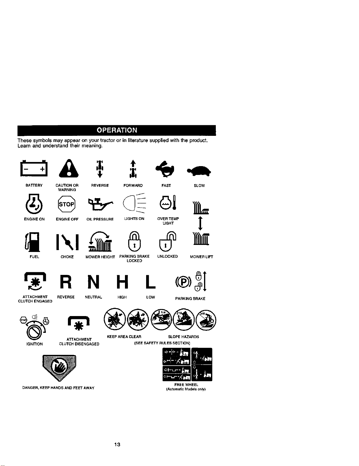
These symbolsmay appear on your tractor or in literature supplied with the product.
Learn and understand their meaning.
A =,
BATFERY CAUTION OR REVERSE FORWARD FAST SLOW
WARNING
ENGINE ON ENGINE OFF OIL PRESSURE LIGHTS ON OVER TEMP
LIGHT
FUEL CHOKE MOWER HEIGHT PARKING BRAKE UNLOCKED
LOCKED
!
MOWERLI_
r_'_ R N H L
ATrACHMENT REVERSE NEUTRAL HIGH LOW PARKING BRAKE
CLUTCH ENGAGED
KEEP AREA CLEAR SLOPE HAZARDS
ATTACHMENT
CLUTCH DISENGAGED (SEE SAFETY RULES SECTION)
DANGER, KEEP HANDS AND FEET AWAY
13
FREE WHEEL
(Automatic Models only)
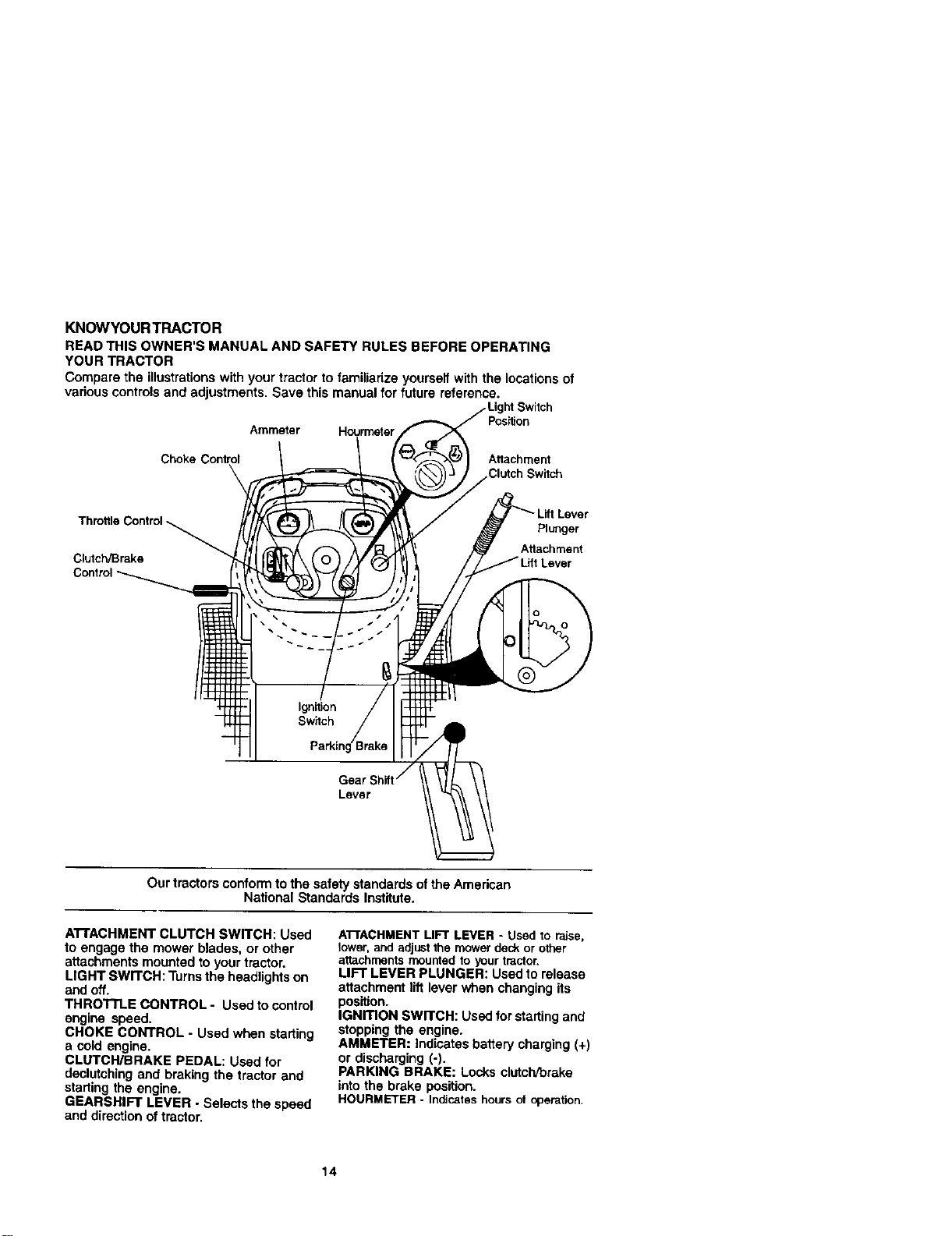
KNOWYOUR TRACTOR
READ THIS OWNER'S MANUAL AND SAFETY RULES BEFORE OPERATING
YOUR TRACTOR
Compare the illustrationswith your tractor to familiarize yourself with the locationsof
various controlsand adjustments. Save this manual for future reference.
Throttle Control
Clutch/Brake
Control
Ammeter Hourmeter
Choke Control Attachment
witch
Plunger
Attachment
Gear_
Lever
Our tractors conform to the safety standards ofthe American
National Standards Institute.
AI"rACHMENT CLUTCH SWITCH: Used
to engage the mower blades, or other
attachments mounted to your tractor.
LIGHT SWITCH: Turnsthe headlightson
and off.
THROTTLE CONTROL - Used to control
engine speed.
CHOKE CONTROL - Used when starting
a cold engine.
CLUTCH/BRAKE PEDAL: Used for
declutching and braking the tractor and
starting the engine.
GEARSHIFT LEVER - Selects the speed
and directionof tractor.
ATTACHMENTUFT LEVER - Used to raise,
lower,and adjustthe mowerdeckor other
attachmentsmountedto yourtractor.
LIFT LEVER PLUNGER: Used to release
attachment lift lever when changing its
position.
IGNmON SWITCH: Usedfor startingand
stoppingthe engine.
AMMETER: Indicates battery charging (+)
or discharging (-).
PARKING BRAKE: Locks clutch/brake
intothe brake position.
HOURMETER- Indicateshoursof operation.
14
Theoperationofanytractorcanresultinforeignobjectsthrownintothe !
eyes, whichcan result in severe eye damage. Always wear safety glasses I
or eye shields while operating your tractor or performing any adjustments
or repairs. We recommend a wide vision safety mask over spectacles, or
standard safety g asses.
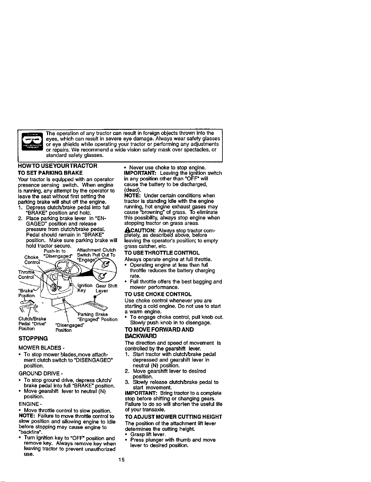
HOWTO USEYOURTRACTOR
TO SET PARKING BRAKE
Yourtractor is equipped with an operator
presence sensing switch. When engine
is running, any attempt by the operator to
leave the seat withoutfirst setting the
parking brake will shut off the engine.
1. Depress clutch/Drakepedal into full
=BRAKE" positionand hold.
2. Place parking brake lever in "EN-
GAGED" positionand release
pressure from clutch/brake pedal.
Pedal should remain in =BRAKE"
position. Make sure parking brake will
holdtractor secure.
Push-Into AttachmentClutch
Choke "Disengage .._.___'SwitchPullOutTo
Th_C°ntr°l " " __'_
__ \Ignition Gear Shift
=Brake Key Lever
P ition o _
">a, ogBrae
Clutch/Brake "Engaged"Position
Pedal=Ddve" =Disengaged"
Position Position
STOPPING
MOWER BLADES -
• To stop mower blades,move attach-
ment clutch switchto =DISENGAGED"
position.
GROUND DRIVE -
• To stop ground ddve, depress clutch/
brake pedal Into full =BRAKE" position.
• Move gearshift lever to neutral (N)
position.
ENGINE -
• Move throttlecontrolto slow position.
NOTE: Failure to move throttlecontrolto
slow position and allowing engine to idle
before stoppingmay cause engine to
"backfire".
• Turn ignitionkey to =OFF" position and
remove key. Always remove key when
leaving tractor to prevent unauthorized
USe.
• Never use choke to stop engine.
IMPORTANT: Leaving the ignition switch
in any position other than "OFF" will
cause the battery to be discharged,
(dead).
NOTE: Under certain conditionswhen
tractor is standing idle with the engine
running, hot engine exhaust gases may
cause "browning" of grass. To eliminate
this possibility,always stop engine when
stoppingtractor on grass areas.
ACAUTION: Always stoptractor com-
pletely, as descdbeiJ above, before
leaving the operator's position;to empty
grass catcher, etc.
TO USE THRO'I'rLE CONTROL
Always operate engine at full throttle.
• Operating engine at less than full
throttle reduces the battery charging
rate.
• Full throttle offers the best bagging and
mower performance.
TO USE CHOKE CONTROL
Usa choke control whenever you are
starting a cold engine. Do not use to start
a warm engine.
• To engage choke control,pull knob out.
Slowly push knob in to disengage.
TO MOVE FORWARD AND
BACKWARD
The direction and speed of movement is
controlledby the gearshift lever.
1. Start tractor with clutch/brake pedal
depressed and gearshift lever in
neutral (N) position.
2. Move gearshift lever to desired
position.
3. Slowly release clutch/brake pedal to
start movement.
IMPORTANT: Bring tractor to a complete
stop before shifting or changinggears.
Failure to do so will shorten the useful life
of your transaxle.
TO ADJUST MOWER CUTTING HEIGHT
The position of the attachment liftlever
determines the cutting height.
• Grasp lift lever.
• Press plunger with thumb and move
lever to desired position.
15
Thecuttingheight range is approxi-
mately 1-1/2 to 4=. The heights are
measured from the ground to the blade
tipwiththeenginenotrunning.These
heights are approximate and may vary
depending upon soil conditions, height of
grass and types of grass being mowed.
• The average lawn should be cutto
approximately 2-1/2 inches during the
coolseason and to over 3 inches
during hotmonths. For healthier and
better looking lawns, mow often and
after moderate growth.
• For best cuttingperformance, grass
over 6 inches in height should be
mowed twice, Make the first cut
relatively high;the second to desired
height.
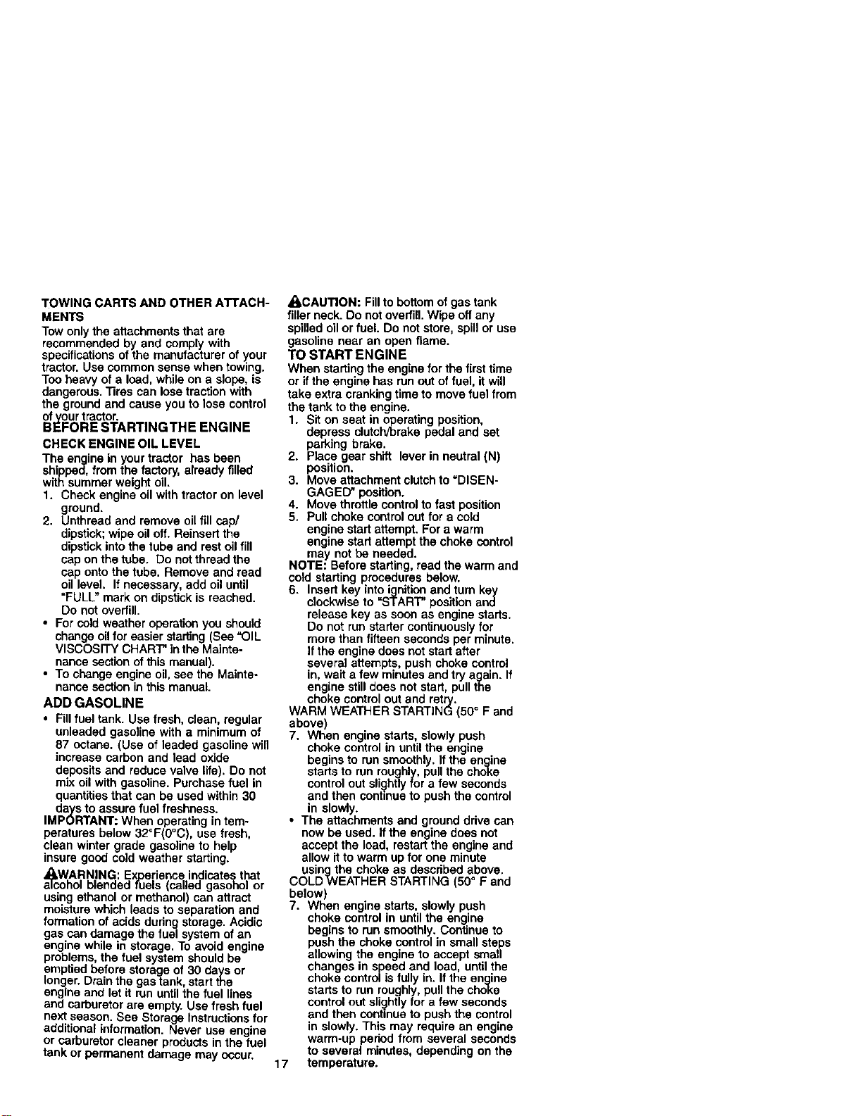
TO ADJUST GAUGE WHEELS
Gauge wheels are properly adjusted
when they are slighllyoff the ground
when mower is at the desired cutting
height in operating position. Gauge
wheels then keep the deck in proper
positionto help prevent scalpingin most
terrain conditions.
NOTE: Be sure tractor ison a flat level
surface.
1. Lower mower and adjust mower to
desired cutting height.
2. Remove retainer spring and clevis pin
which secure each gauge wheel bar.
3. Lower gauge wheels to ground. Raise
gauge wheels slightlyto align holes in
bracket and gauge wheel bar and
insett clevis pin. Gauge wheels
should be slightly off the ground.
4. Replace re'_ainerspring into clevis pin.
5. Besure all gauge wheels are in the
same setting.
IMPORTANT: Be sure to readjust gauge
wheels if you change the cuttingheight
ofthe mower deck.
Retainer
Clevis
.... Pin
TO OPERATE MOWER
Yourtractor is equipped with an operator
presence sensing switch. Any attempt by
the operator to leave the seat with the
engine runningand the attachment clutch
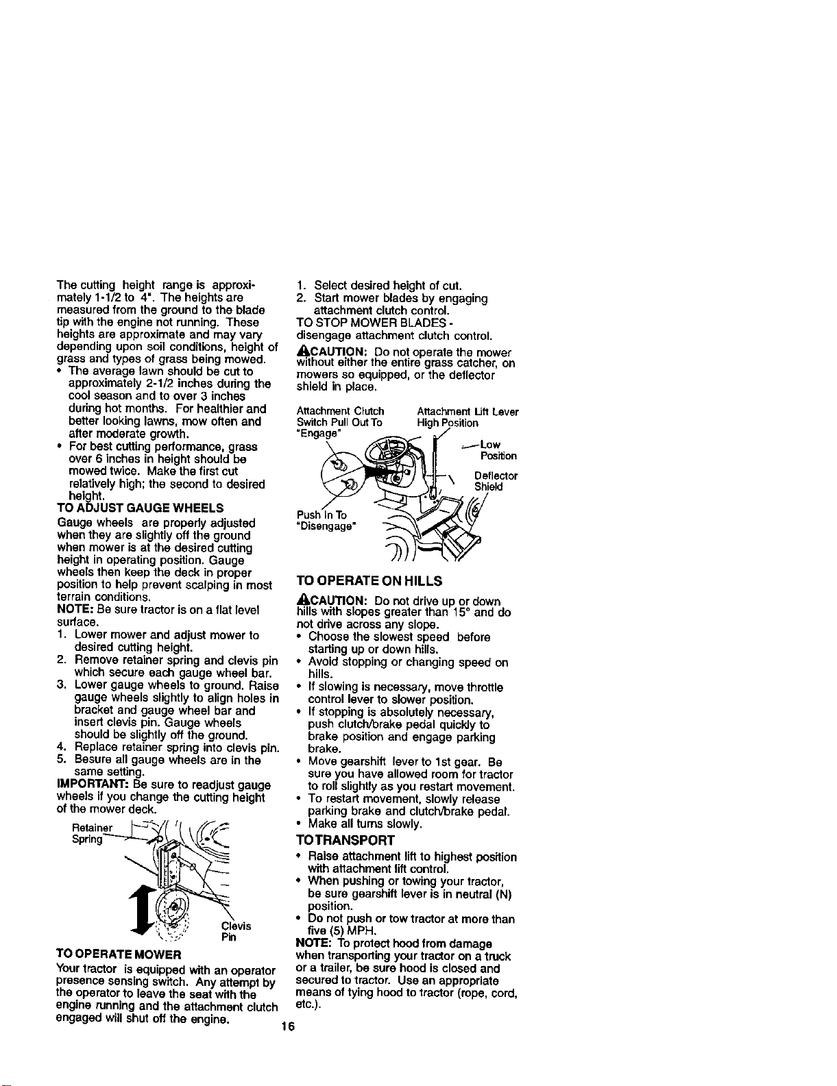
1. Select desired height of cut,
2. Start mower blades by engaging
attachment clutchcontrol.
TO STOP MOWER BLADES -
disengage attachment clutch control.
,_kCAUTION: Do not operate the mower
withouteither the entire grass catcher, on
mowers so equipped, or the deflector
shield in place.
Attachment Clutch
Switch PullOut To
=Engage"
Attachment lifl Lever
High Position
_Low
position
•\ Deflector
Shield
Push In To
"Disengage"
TO OPERATE ON HILLS
_I,CAUTION: Do not drive up or down
hills with slopes greater than 15° and do
not drive across any slope.
• Choose the slowest speed before
starting up or down hills.
• Avoid stopping or changing speed on
hilts.
• If slowing is necessa_, move throttle
controllaver to slower position.
• If stoppingis absolutely necessary,
push clutch/brake pedal quicklyto
brake positionand engage parking
brake.
• Move gearshift lever to 1stgear. Be
sure you have allowed room fortractor
to roll slightlyas you restart movement.
• To restart movement, slowly release
parking brake and clutch/brake pedal.
• Make all turns slowly.
TOTRANSPORT
• Raise attachment lift to highest position
with attachment liftcontrol.
• When pushing or towing your tractor,
be sure gearshift lever is in neutral (N)
position.
• Do not push or towtractor at morethan
five (5) MPH.
NOTE: To protect hoodfrom damage
when transporting yourtractor on a truck
or a trailer, be sure hood is closed and
securedto tractor. Use an appropriate
means of _ying hood to tractor (rope, cord,
etc.).
engaged will shut off the engine.
16
TOWING CARTS AND OTHER ATrACH-
MEN'IS
Tow onlythe attachments that are
recommended by and comply with
specifications of the manufacturer of your
tractor. Use common sense when towing.
Too heavy ofa loud, while on a slope, =s
dangerous. Tires can lose traction with
the ground and cause you to lose control
ofvour tractor.
BEFORE STARTINGTHE ENGINE
CHECK ENGINE OIL LEVEL
The engine in your tractor has been
shipped, from the factory, already filled
with summer weight oil.
1. Check engine oil with tractor on level
ground.
2. Unthread and remove oil fill cap/
dipstick;wipe oil off. Reinsert the
dipstickinto the tube and rest oil fill
cap on the tube. Do not thread the
cap onto the tube. Remove and read
oil level. If necessary, add oil until
"FULL" mark on dipstickis reached.
Do not overfill.
• For cold weather operation you should
change oilfor easier starting(See "OIL
VISCOSITY CHART" in the Mainte-
nance sectionof this manual).
• To change engine oil, see the Mainte-
nance section in thismanual.
ADD GASOLINE
• Fillfuel tank. Use fresh, clean, regular
unleaded gasoline with a minimumof
87 octane. (Use of leaded gasoline will
increase carbon and lead oxide
deposits and reduce valve life). Do not
mix oil with gasoline. Purchase fuel in
quantitiesthat can be usedwithin 30
days to assure fuel freshness.
IMPORTANT: When operating in tem-
peratures below 32°F(O°C), use fresh,
clean winter grade gasoline to help
insure good cold weather starting.
a_cWARNING: Experience indicates that
ohol blended fuels (called gasohol or
using ethanol or methanol) can attract
moisturewhich leads to separation and
formation of acids during storage. Acidic
gas can damage the fuel system of an
engine while in storage. To avoid engine
problems, the fuel system should be
emptied before storage of 30 days or
longer.Drain the gas tank, start the
engine and let it run untilthe fuel lines
and carburetor are empty. Use fresh fuel
nextseason. See Storage Instructionsfor
additional information. Never use engine
or carburetor cleaner productsin the fuel
tank or permanent damage may occur.
ACAUTION: Fillto bottom of gas tank
filler neck. Do not overfill Wipe off any
spilled oil or fuel. Do not store, spill or use
gasoline near an open flame.
TO START ENGINE
When starting the engine for the first time
or if the engine has run out offuel, it will
take extra cranking time to move fuel from
the tank to the engine.
1. Sit on seat in operating position,
depress clutch/brake pedal and set
parking brake.
2. Place gear shift lever in neutral (N)
position.
3. Move attachment clutch to =DISEN-
GAGED" position.
4. Move throttle control to fast position
5. Pull choke control out for a cold
engine start attempt. For awarm
engine start attempt the choke control
may not be needed.
NOTE: Before starting, read the warm and
cold starting procedures below.
6. Insert key into ignition and turn ke_/
clockwise to "START" position an(I
release key as soon as engine stads.
Do not run starter continuously for
more than fifteen seconds per minute.
If the engine does not start after
several attempts, push choke control
in, wait afew minutes and try again. If
engine still does not start, pull the
choke control out and retry, o
WARM WEATHER STARTING (50 F and
above)
7. When engine starts, slowly push
choke control in untilthe engine
begins to runsmoothly. If the engine
starts to run roughly, pull the choke
control out slightlyfor a few seconds
and then continue to push the control
in slowly.
• The attachments and ground drive can
now be used. If the engine does not
accept the load, restart the engine and
allow it to warm up for one minute
using the choke as described above.
COLDWEATHER STARTING (50 F and
below)
7. When engine starts, slowly push
choke control in until the engine
begins to run smoothly. Continue to
push the choke control in small steps
allowing the engine to accept small
changes in speed and load, untilthe
choke control isfully in. Ifthe engine
starts to run roughly,pull the choke
control out slightlyfor a few seconds
and then continue to push the control
in slowly. This may require an engine
warm-up period from several seconds
to several minutes, depending on the
17 temperature.
• Theattachmentscanbeusedduring
theengine warm-up period and may
require the choke control be pulled out
slightly.
NOTE=ffat a highaltitude(above3000 feet)
orincoldtemperatures(below3_ F)the
carburetorfuel mixture may needto be
a_usted forbestenginepeffo.n'na_r_ce.See
"TO ADJUST CARBURETOR intheService
andA_ustrnents sec_onof thismanual.
MOWlNGTIPS
• Mower should be propedy Leveledfor
best mowing performance. See "TO
LEVEL MOWER HOUSING" inthe
Service end Adjustments section ofthis
manual.
• The left hand side of mower should be
used for trimming.
• Drive so that clippings are discharged
onto the area that has been cut. Have
the cutarea to the rightofthe tractor.
This will result in a more even distribu-
lion of clippingsand more uniform
cutting.
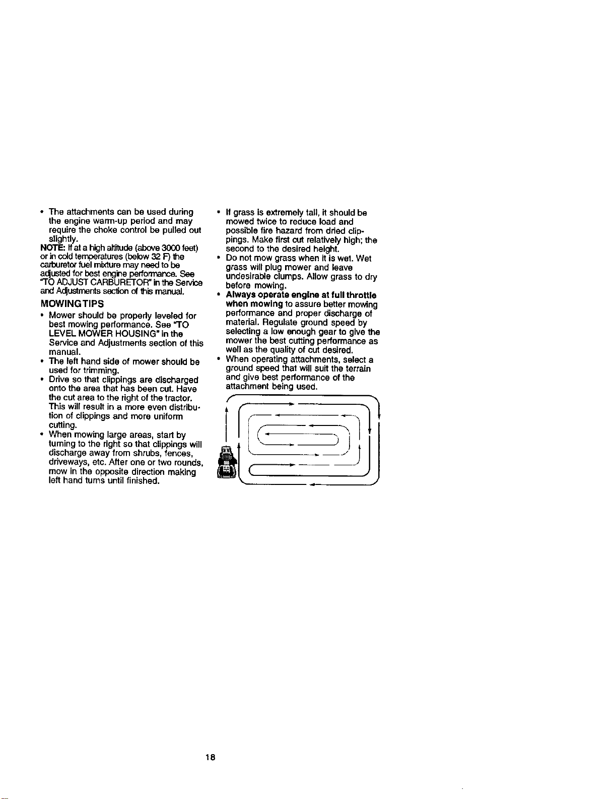
• When mowing large areas, start by
turningto the right so that clippings will
discharge away from shrubs, fences,
driveways, etc. After one or two rounds,
mow in the opposite direction making
left hand turns untilfinished.
• If grass is extremely tall, itshould be
mowed twice to reduce load and
possiblefire hazard from dded clip-
pings. Make first cut relativelyhigh;the
second to the desired height.
• Do not mow grass when itis wet. Wet
grass will plug mower and leave
undesirable clumps. Allow grass to dry
before mowing.
• Always operate engine at full throttle
when mowing toassure better mowing
performance end proper discharge of
material. Regulate ground speed by
selecting a low enough gear to give the
mower the best cutting performance as
well as the qualityof cut desired.
• When operating attachments, select a
groundspeed that will suitthe terrain
and give best performance ofthe
aftachment being used.
f
J
18
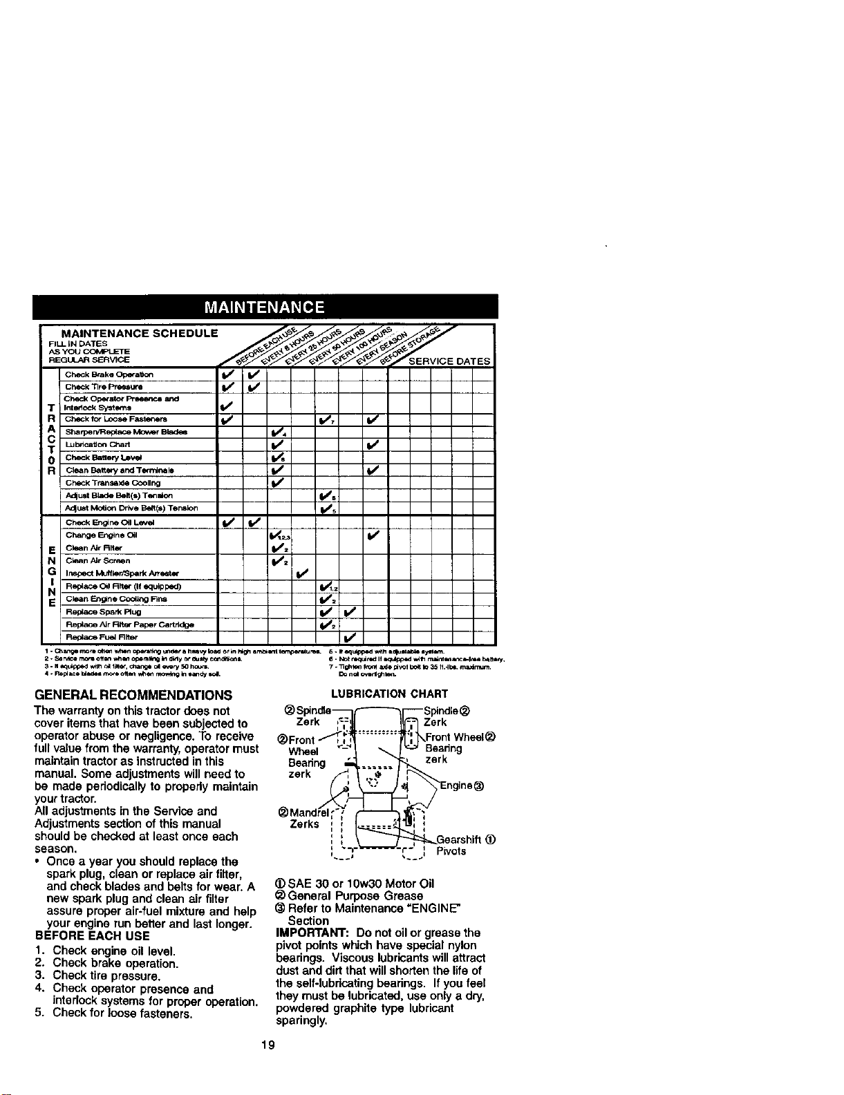
_-_,_'_ SERVIC E DATES
Check Brake Op, orat_ofl _/ ft_
CheCk Tire Pressure _
CheCk Operato_ Pr_ and
R CheckforLooseFasleners _ IbJz If
.SharperYRep_..eMowerBlades I/'4
T L_=.,o. chart l/ V'
0 Ch,_J<B_o,y_ I./.
R CleanBatte_andT(_-nllr_ls _ 4b_
CheCk Trans.)de COOling
Adjust Blade Be_t(s) T_malon _s
_d_ust Motior= Drive Be/t (s) Tension _s
ch,_<E,'_ C,IL_= V' V"
E clean A_rRlter _=
N Clean A_rScreen IV/=
G InSpectk'x_llk)rP3parkA_rester
i_ Replace (311F_tter(If equipped) V_=
E Clean _glne _ll_g Fins _=
R_aC_spar_F_ug I,/ t,/
Replace Air Rlter P_per Cart_dge ll_/_
P_ F_ R_, V'
GENERAL RECOMMENDATIONS
The warranty on this tractor does not
cover items that have been subjected to
operator abuse or negligence. To receive
full value from the warranty,operator must
maintaintractor as instructedin this
manual. Some adjustments willneed to
be made periodically to properly maintain
your tractor.
All adjustments in the Service and
Adjustments section of this manual
should be checked at least once each
season.
• Once a year you should replace the
spark plug, clean or replace air filter,
and check blades and beltsfor wear. A
new spark plug and clean air filter
assure proper air-fuel mixture and help
your engine run better and last longer.
BEFORE EACH USE
1. Check engine oil level.
2. Check brake operation.
3. Check tire pressure.
4. Check operator presence and
interlock systems for proper operation.
5. Check for loose fasteners.
LUBRICATION CHART
_ Spindte_ (-----_1--- Spindle(_
Zerk ,=:, Zerk
i I,
(_ Front __Front Whe_l _
_ Mandre/_l_"_>'/,'_
Zerks ; I 1_..3_1 I,,, ;
_) SAE 30 or 10w30 Motor Oil
_) General Purpose Grease
(_ Refer to Maintenance =ENGINE*
Section
IMPORTANT: Do not oil or grease the
pivot points which have special nylon
bearings. Viscous lubricantswill attract
dust and dirtthat willshorten the life of
the self-lubdcatingbearings. If you feel
they must be lubricated,use only a dry,
powdered graphite type lubricant
sparingly.
19
TRACTOR
Alwaysobservesafety rules when
pedorming any maintenance.
BRAKE OPERATION
If tractorrequiresmore than six (6) feet
stoppingdistance at high speed in
highestgear, then brake must be ad-
justed. (See "TO ADJUST BRAKE" in the
Service and Adjustments section of this
manuel).
TIRES
• Maintain proper air pressure in all tires
(See "PRODUCT SPECIFICATIONS"
section ofthis manual)_
• Keep tiresfree of gasoline, oil,or insect
control chemicals which can harm
rubber.
• Avoid stumps, stones, deep ruts, sharp
objects and other hazards that may
cause tire damage.
NOTE; To seal tire punctures and prevent
flat tires due to slow leaks, tire sealant
may be purchased from your local parts
dealer. Tire sealant also prevents tire dry
rot and corrosion.
OPERATOR PRESENCE SYSTEM
Be sure that operator presence and
interlock systems are working properly. If
your tractor does notfunction as de-
scribed below, repair the problem
immediately.
• The engine should not start unless the
clutch/brake pedal is fully depressed
and attachment clutch control is in the
disengaged position.
• When the engine is running, any
attempt by the operatorto leave the
seat without first setting the parking
brake should shut off the engine.
• When the engine is running and the
attachment clutch is engaged, any
attempt by the operatorto leave the
seat shouldshut offthe engine.
• The attachment clutch should never
operate unless the operator is in the
seat.
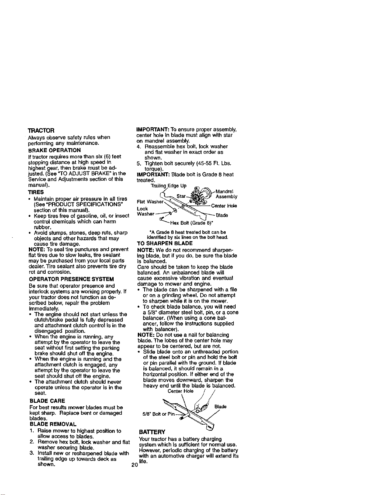
IMPORTANT: To ensure proper assembly,
center hole in blade must align with star
on mandrel assembly.
4. Reassemble hex bolt, lock washer
and flat washer in exact order as
shown.
5. Tighten bolt securely (45-55 Ft. Lbs.
torque).
IMPORTANT: Blade bolt is Grade 8 heat
treated.
TrailingEdgeUp _'_ - Mandrel
*A Grade8 heattreatedboltcanbe
identifiedbysixlinesonthebolthead.
TO SHARPEN BLADE
NOTE: We do not recommend sharpen-
ing blade, but if you do, be sure the blade
is balanced,
Care should be taken to keep the blade
balanced. An unbalanced blade will
cause excessive vibration and eventual
damage to mower and engine.
• The blade can be sharpened with a file
or on a gdndingwheel. Do notattempt
to sharpen while it is on the mower.
• To check blade balance, you will need
a 5/8" diameter steel bolt, pin, or a cone
balancer. (When using a cone bal-
ancer, follow the instructionssupplied
with balanoer).
NOTE: Do not use a nail for balancing
blade. The lobes of the center hole may
appear to be centered, but are not.
• Slide blade onto an unthraaded portion
of the steel bolt or pin and hold the boil
or pin parallel with the ground. If blade
is balanced, it should remain in a
horizontal position. If either end of the
blade moves downward, sharpen the
heavy end untilthe blade is balanced.
Center Hole
BLADE CARE
For best results mower blades must be
kept sharp. Replace bent or damaged
blades.
BLADE REMOVAL
1. Raise mower to highest positionto
allow access to blades.
2. Remove hex bolt, lock washer and flat
washer securing blade.
3. Install new or resharpened blade with
trailingedge up towards deck as
shown.
Blade
5/8" Bolt or Pin-
BATrERY
Your tractor has a battery charging
system which is sufficient fornormal use.
However, periodic charging of the battery
with an automotive charger will extend its
20 life.
• Keepbattery and terminals clean.
• Keep battery bolts tight.
• Keep small vent holes open.
• Recharge at 6-10 amperes for I hour.
NOTE; The odginal equipment battery on
your tractor is maintenance free. Do not
attempt to open or remove caps or covers.
Adding or checking level of electrolyte is
not necessary.
TO CLEAN BA'I-rERY AND TERMINALS
Corrosion and dirt on the battery and
terminals can cause the battery to "leak"
power.
1. Remove terminal guard.
2. Disconnect BLACK battery cable first
then RED battery cable and remove
batteryfrom tractor.
3. Rinse the batterywith plain water and
dry.
4. Clean terminals and battery cable
ends with wire brush until bright.
5. Coat terminals with grease or petro-
leum jelly.
6. Reinstall battery (See "REPLACING
BA'I-rERY" in the SERVICE AND
ADJUSTMENTS section of this
Check V-belts for deterioration and wear
after 100 hours of operation and replace
if necessary.The beltsare not adjustable.
Replace belts ifthey begin to slipfrom
wear.
TRANSAXLE COOLING
Keep transaxle free from build-up of dirt
and chaff which can restdct cooling.
ENGINE
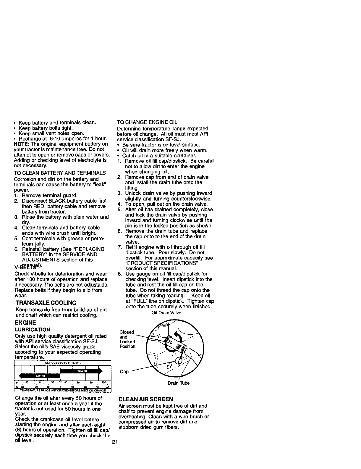
LUBRICATION
Only use high quality detergent oil rated
withAPI serviceclassificationSF-SJ.
Select the oil'sSAE viscosity grade
according to your expected operating
TO CHANGE ENGINE OIL
Determine temperature range expected
before oil change. All oil must meet API
service classification SF-SJ.
• Be sure tractor is on level surface.
• Oil will drain more freely when warm.
• Catch oil in a suitable container.
1. Remove oil fill cap/dipstick. Be careful
not to allow did to enter the engine
when changing oil.
2. Remove cap from end of drain valve
and install the drain tube onto the
fitting.
3. Unlock drain valve by pushing inward
slightly and turning counterclockwise.
4. To open, pull out on the drainvalve.
5. After oil has drained completely, close
and lock the drain valve by pushing
inward and turning clockwiseuntil the
pin is in the locked positionas shown.
6. Remove the drain tube and replace
the cap onto to the end of the drain
valve.
7. Refill engine with oil through oil fill
dipstick tube. Pour slowly. Do not
overfill. For approximate capacity see
"PRODUCT SPECIFICATIONS"
section of this manual.
8. Use gauge on oil fill cap/dipstick for
checking level. Insert dipstick into the
tube and rest the oil fill cap on the
tuba. Do not thread the cap onto the
tube when taking reading. Keep oil
at "FULL" line on dipstick. Tighten cap
onto the tube securely when finished.
Oil DrainValve
Closed
and
Locked
Position
Cap
DrainTube
Change the oil after every 50 hours of
operation or at least once a year if the
tractor is not usedfor 50 hours in one
year.
Check the crankcase oil level before
starting the engine and after each eight
(8) hours ofoperation. Tighten oil fill cap/
dipstick securely each time you check the
oil level. 21
CLEAN AIR SCREEN
Air screen must be kept free of dirtand
chaff to prevent engine damage from
overheating. Clean with a wire brush or
compressed air to remove dirt and
stubborn dded gum fibers.
CLEAN AIR INTAKE/COOLING AREAS
To insure proper cooling, make sure the
grass screen, cooling fins, end other
external surfaces of the engine are kept
clean at all times.
Every 100 hours of operation (more often
under extremely dusty, dirty conditions),
remove the blower housing and other
coolingshrouds. Clean the cooling fins
and external surfaces as necessary. Make
sure the cooling shrouds are reinstalled.
NOTE: Operating the engine with a
blocked grass screen, dirty or plugged
coolingfins, and/or cooling shrouds
removed will cause engine damage due
to overheating,
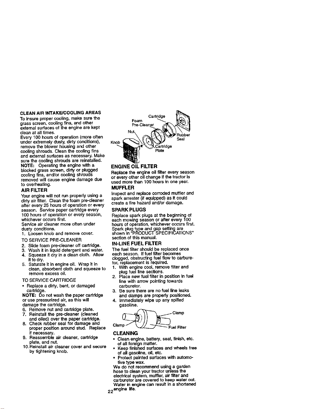
AIR FILTER
Yourengine will not run properly using a
dirty air filter. Clean the foam pre-cleaner
after every 25 hours of operation or every
season. Service paper cartridge every
100 hours of operation or every season,
whichever occurs first.
Service air cleaner more often under
dusty conditions.
1. Loosen knob and remove cover.
TO SERVICE PRE-CLEANER
2. Slide foam pre-cleaner off cartridge.
3. Wash it in liquid detergent and water.
4. Squeeze it dry in a clean cloth. Allow
itto dry.
5. Saturate it in engine oil. Wrap it in
clean, absorbent cloth and squeeze to
remove excess oil.
TO SERVICE CARTRIDGE
• Replace a dirty, bent, or damaged
cartridge.
NOTE: Do not wash the paper cartridge
or use pressurized air, as this will
damage the cartridge.
6. Remove nut and cartridge plate.
7. Reinstall the pre-cleaner (cleaned
and oiled) over the paper cartridge.
8. Check rubber seal for damage and
proper position around stud. Replace
if necessary.
9. Reassemble air cleaner, cartridge
plate, and nut.
10.Reinstall air cleaner cover and secure
by tightening knob.
Knob
Foam CaM_
Pm-Cleaner
Plate
Rubber
Seal
ENGINE OIL FILTER
Replace the engine oil filter every season
or every other oilchange if the tractor is
used more than 100 hours in one year.
MUFFLER
Inspect and replace corroded muffler and
spark arrester (if equipped) as it could
create a fire hazard end/or damage.
SPARK PLUGS
Replace spark plugs at the beginningof
each mowing season or after every 100
hours ofoperation, whichever occursfirst.
Spark plug type and gap setting are
shown in "PRODUCT SPECIFICATIONS"
sectionof this manual.
IN-LINE FUEL FILTER
The fuel filter should be replaced once
each season. If fuel filter becomes
clogged, obstruct!ngfuel flow to carbure-
tor, replacement Is required.
1. W'dhengine cool, remove filter and
plug fuel line sections,
2. Place new fuel filter in positionin fuel
line with arrow pointingtowards
carburetor.
3. Be sure there are no fuel line leaks
and damps are properly positioned.
4. Immediately wipe up any spilled
gasoline.
_ Clamp
Clamp/ __Fuel Filter
CLEANING
• Clean engine, battery, seat, finish,etc.
of all foreign matter.
• Keep finished surfaces and wheels free
ofall gasoline, oil, etc.
• Protect painted surfaces with automo-
tive type wax.
We do not recommend using a garden
hose to clean your tractor unless the
electrical system, muffler,air filterand
carburetor are covered to keep water out.
Water in engine can resultin a shortened
22engine life.
,_CAUTION: BEFORE PERFORMING ANY SERVICE OR ADJUSTMENTS:
1. Depress clutch/brake pedal fully and set parking brake.
2. Place gearshift lever in neutral (N) position.
3. Place attachment clutch in "DISENGAGED" position.
4. Turn ignitionkey "OFF" and remove key.
5. Make sure the blades and all moving parts have completely stopped.
6. Disconnect spark plug wire from spark plug and place wire where it cannot
come in contact with plug.
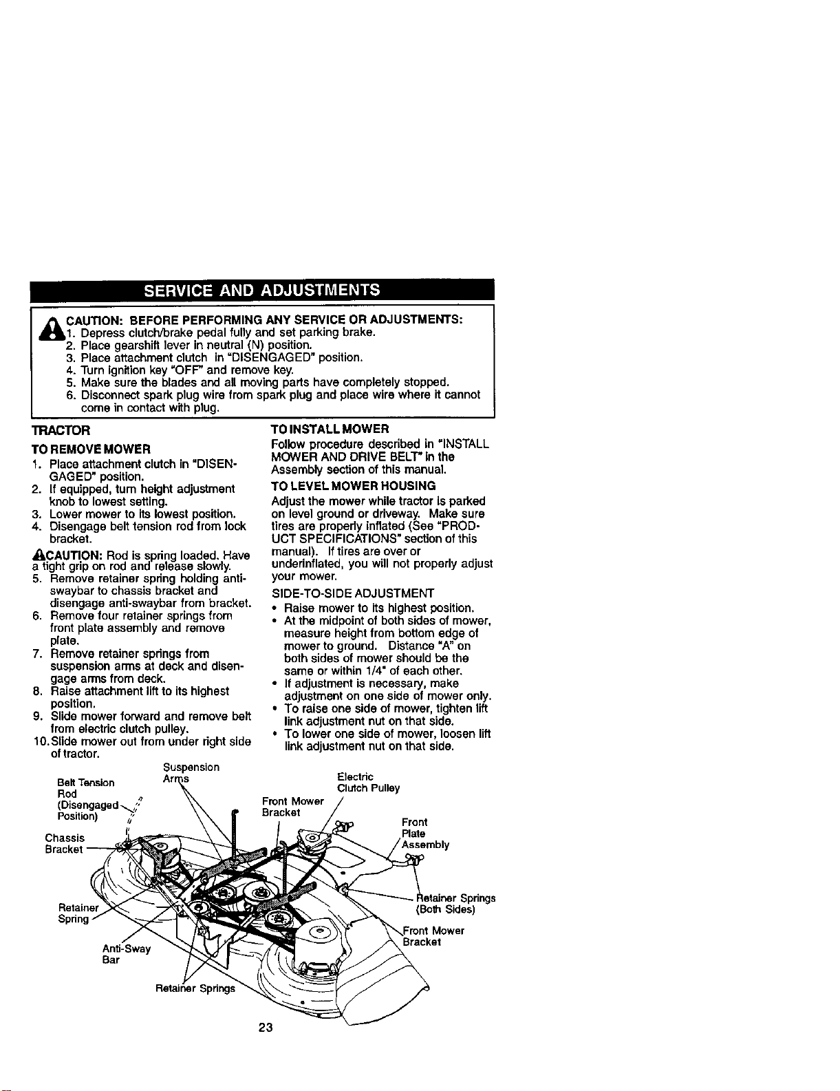
TRACTOR
TO REMOVE MOWER
1. Place attachment clutchin "DISEN-
GAGED" position.
2. If equipped, tum height adjustment
knobto lowest setting.
3. Lower mower to its lowest position.
4. Disengage belt tension rodfrom lock
bracket.
_,CAUTION: Rod is spring loaded. Have
a tight gripon rod and release slowly•
5. Remove retainer spring holding anti-
swaybar to chassis bracketand
disengage anti-swaybar from bracket.
6. Remove four retainer springsfrom
front plate assembly and remove
plate.
7. Remove retainer springsfrom
suspension arms at deck and disen-
gage arms from deck.
8. Raise attachment liftto its highest
position.
9. Slide mower forward and remove belt
from electric clutch pulley.
10.Slide mower out from under rightside
oftractor.
Suspension
BeltTension
Rod
• 4*
(Disengaged_,,
Positon) /_'
Chassis
TO INSTALL MOWER
Follow procedure described in "INSTALL
MOWER AND DRIVE BELT"in the
Assembly section of this manual
TO LEVEL MOWER ROUSING
Adjustthe mower while tractor is parked
on level ground or driveway. Make sure
tires are properly inflated (See "PROD-
UCT SPECIFICATIONS" sectionof this
manual). If tiresare over or
underinflated, you will not properly adjust
your mower.
SIDE-TO-SIDE ADJUSTMENT
• Raise mower to its highest position.
• At the midpointof both sides of mower,
measure heightfrom bottom edge of
mower to ground. Distance "A" on
both sides of mower should be the
same or within t/4" of each other.
• If adjustment is necessa_, make
adjustment on one side of mower only.
• To raise one side of mower, tightenlift
linkadjustment nut on that side.
• To lower one side of mower, loosen lift
link adjustment nut on that side.
Etectdc
Clutch Pulley
Front Mower
Bracket
Front
Plate
Retainer
Anti-Sway
Bar
Spdngs
(Both Sides)
Mower
Bracket
23
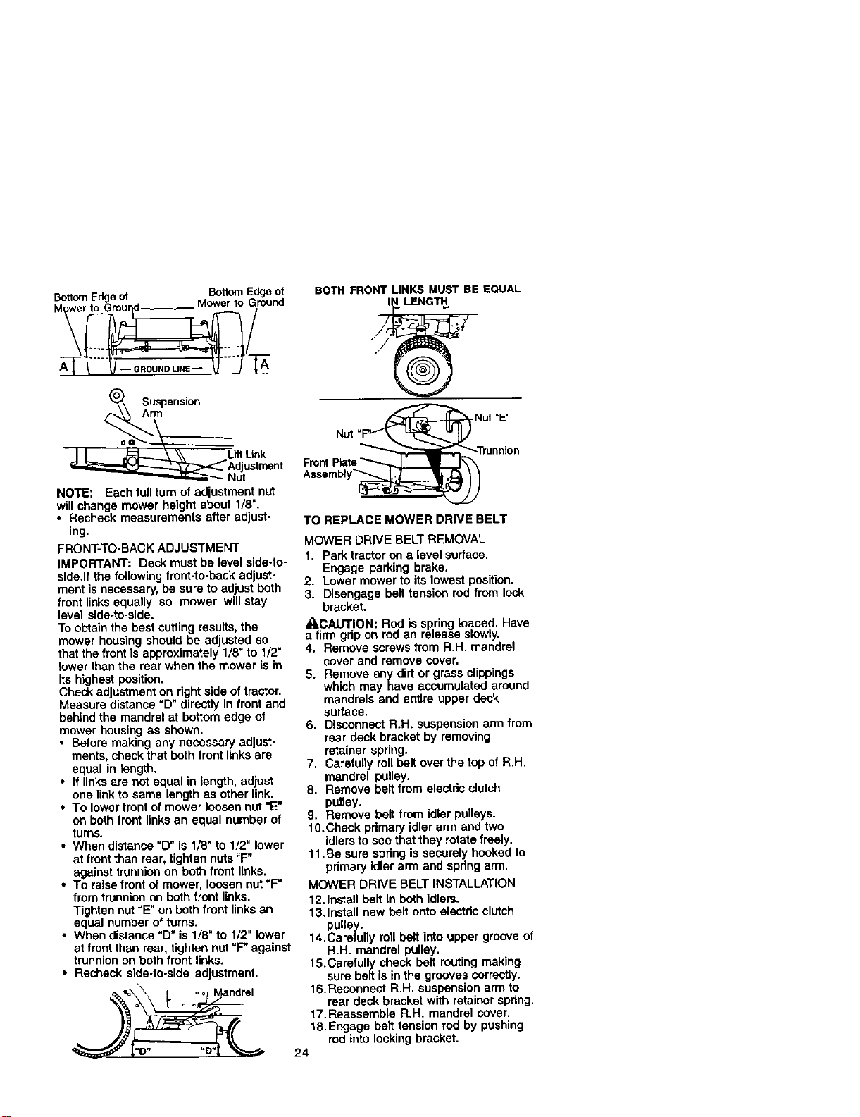
Botio,'nEdgeof BstlomEdgeof
,T: iround
8uspens_on
L_ Link
Adjustment
Nut
NOTE: Each full turnof adjustment nut
will change mower height about 1/8".
• Recheck measurements after adjust-
ing.
FRONT-TO-BACK ADJUSTMENT
IMPORTANT: Deck must he level side-to-
side.If the following front-to-back adjust-
ment is necessary, be sure to adjust both
front linksequally so mower will stay
level side.to-side.
To obtainthe best cutting results, the
mower housing should be adjusted so
thatthe front is approximately 1/8"to 1/2"
lower than the rear when the mower is in
its highest position.
Check adjustment on rightside of tractor.
Measure distance "D" directly in front and
behind the mandrel at bottom edge of
mower housing as shown.
• Before making any necessary adjust-
ments, check that both front linksare
equal in length.
• If linksare not equal in length, adjust
one linkto same length as other link.
• To lowerfront of mower loosen nut =E"
on both front links an equal number of
turns.
• When distance "D" is 1/8" to 1/2" lower
at front then rear, tighten nuts"F"
against trunnion on both front links.
• To raisefront of mower, loosen nut =F"
from trunnion on both front links.
Tighten nut "E"on both front links an
equal number of turns.
• When distance "D" is 1/8" to 1/2" lower
at front than rear, tighten not =F" against
trunnionon both front links.
• Recheck side-to-side adjustment.
=0 oo Mandrel
a o o
BOTH FRONT LINKS MUST BE EQUAL
Assembty_
TO REPLACE MOWER DRIVE BELT
MOWER DRIVE BELT REMOVAL
1. Park tractor on a level surface.
Engage parking brake.
2. Lower mower to its lowest position.
3. Disengage belt tension rod from lock
bracket.
=CLCAUTION: Rod is spring loaded. Have
a firm grip on rod an release slowly.
4. Remove screws from R.H. mandrel
cover and remove cover.
5. Remove any dirt or grass clippings
which may have accumulated around
mandrels and entire upper deck
SUrface.
6. Disconnect R.H. suspension arm from
rear deck bracket by removing
reteiner spring.
7. Carefully rollbelt over the topof R.H.
mandrel pulley.
8. Remove belt from electric clutch
pulley.
9. Remove belt from idler pulleys.
10.Check primanj idler arm and two
idlersto see thatthey rotate freely.
11.Be sure spring is securely hooked to
primary idler arm and spring arm.
MOWER DRIVE BELT INSTALLATION
12.Install belt in both idlers.
13.Install new belt onto electdo clutch
pulley.
14.Carefully roll belt into upper groove of
R.H. mandrel pulley.
15.Carefully check belt routing making
sure belt is in the grooves correctly.
16.Reconnect R,H. suspension arm to
rear deck bracket with retainer spring,
17.Reassemble R.H. mandrel cover,
18,Engage belt tension rod by pushing
rod into locking bracket.
24
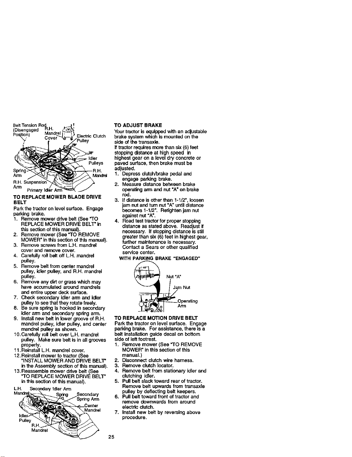
Posi_n) Mandrel
Electdc Clutch
. Idler
Pulleys
Spdn
Arm Mandrel
R.H. Suspens;ol
Arm
Pdmar_
TO REPLACE MOWER BLADE DRIVE
BELT
Park the tractor on levelsurface. Engage
parking brake.
1. Remove mower ddve belt (See "TO
REPLACE MOWER DRIVE BELT"in
thissection ofthis manual).
2. Remove mower (See "TO REMOVE
MOWER" inthis sectionofthis manual).
3. Remove screws from L.H. mandrel
cover and removecover.
4. Carefully ronbelt off L.H. mandrel
pulley.
5. Remove belt from center mandrel
pulley, idler pulley, and R.H. mandrel
pulley.
6. Remove any dirt or grasswhich may
have accumulated around mandrels
and entire upper deck surface.
7. Check secondary idler arm and idler
pulley to see thatthey rotatefreely.
8. Be surespringis hooked in secondary
idler arm and secondaryspring arm.
9. Installnew belt in towergrooveof R.H.
mandrel pulley, idler pulley, and center
mandrel pulley as shown.
10.Carefully rollbelt over L.H. mandrel
pulley. Make sure belt is in all grooves
properly.
11. Reinstall L.H. mandrel cover.
12. Reinstallmower to tractor (See
"INSTALL MOWER AND DRIVE BELT"
in the Assemblysection of this manual).
13. Reassemble mower drive belt (See
"TO REPLACE MOWER DRIVE BELT"
in thissectionof this manual).
L.H. SecondaP/IdlerArm
Secondary
Arm
Mandrel
Pulley
R.H.
Mandrel
TO ADJUST BRAKE
Your tractor is equipped with an adjustable
brake system which is mounted onthe
side of the transaxle.
if tractorrequiresmorethan six (6) feet
stopping distanceat highspeed in
highest gear on a level dry concrete or
paved surface, then brake must be
adjusted.
1. Depress clutch/brake pedal and
engage parking brake.
2. Measure distance between brake
operatingarm and nut "A" on brake
rod.
3. If distance is otherthan 1-1/2", loosen
jam nut and tum nut "A" untildistance
becomes 1-1/2". Retightan jam nut
againstnut=A".
4. Road test tractorfor proper stopping
distanceas statedabove. Readjust if
necessary. If stoppingdistanceis still
greater than six (6) feet in highestgear,
further maintenance is necessary.
Contact a Sears or other qualified
service center.
WITH PARKING BRAKE "ENGAGED"
25
Nut =A"
Jam Nut
TO REPLACE MOTION DRIVE BELT
Park the tractor on level surface. Engage
parking brake. For assistance, there isa
belt installationguide decal on bottom
side of left footrest.
1. Remove mower (See "TO REMOVE
MOWER" inthis section ofthis
manual.)
2. Disconnect clutch wire hamese.
3. Remove clutch tocator.
4. Remove belt from stationary idler and
clutching idler.
5. Pullbelt slack toward rear of tractor.
Remove belt upwards from transaxle
pulley by deflecting belt keepers.
6. Pullbelt toward front oftractor and
remove downwards from around
electric clutch.
7. Install new belt by reversing above
procedure.
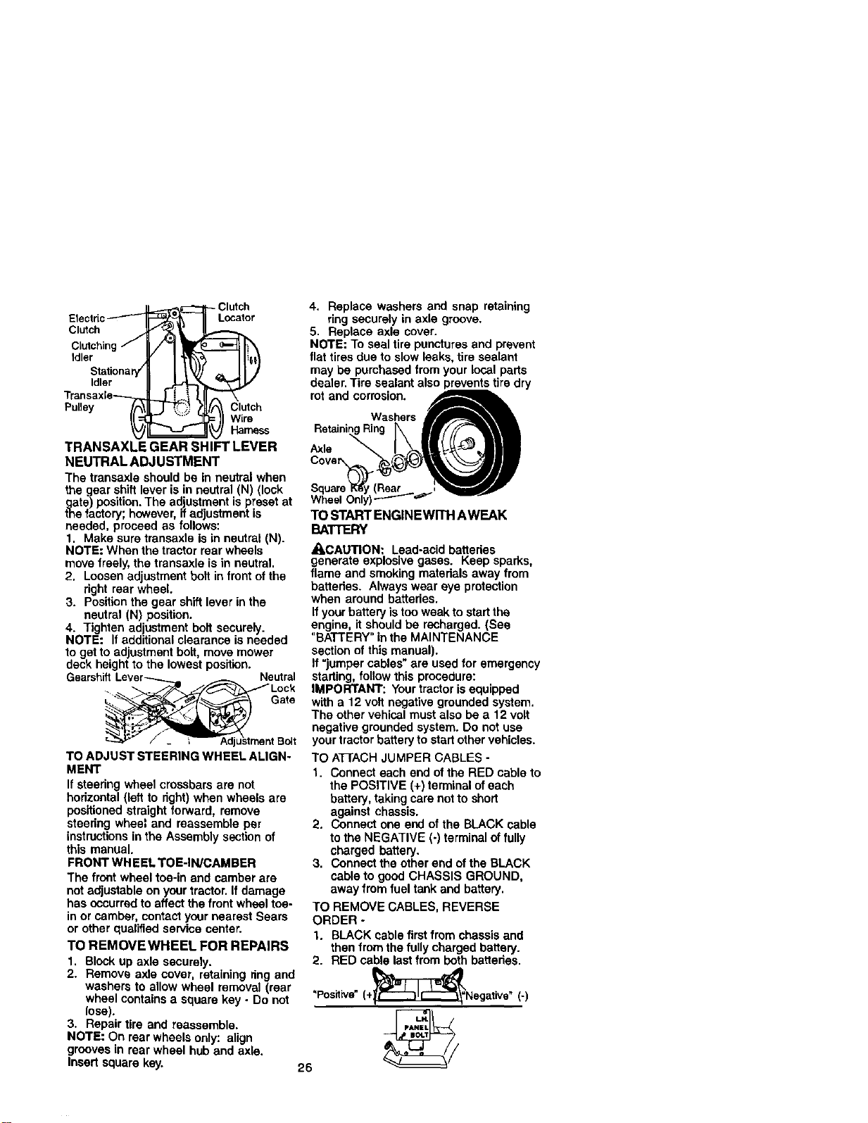
Clutch
Electdc Locator
C=oh
Clutching/ U/'3 lr__- -_lh\
Idlestati°naP_r I 1'_)_ , 11")
Transaxle_i l,ll
Pulley /A\I[J _7",;_?Jl/Clutch
TRANSAXLE GEAR SHIFT LEVER
NEUTRAL ADJUSTMENT
The traneaxle should be in neutral when
the gear shift lever is in neutral (N) (lock
tghate)position. The adjustment is preset at
e fautory; however, ffadjustment is
needed, proceed as follows:
1. Make sure traneexle is in neutral (N).
NOTE: When the tractor rear wheels
move freely, the transaxla is in neutral.
2. Loosen adjustment bolt in front ofthe
right rear wheel.
3. Position the gear shift lever in the
neutral (N) position.
4. Tighten adjustment bolt securely.
NOTE: If additional clearance is needed
to get to ad ustment bolt, move mower
deck heightto the lowest position.
Gearshift Lever_.._, Neutral
_ustrnent Bolt
TO ADJUST STEERING WHEEL ALIGN-
MENT
If steedng wheel crossbars are not
horizontal (left to right) when wheels are
positioned straight forward, remove
steedng wheel and reassemble per
instructionsin the Assembly section of
this manual.
FRONT WH EELTOE-IN/CAMBER
The front wheel toe-in and camber are
notadjustable on your tractor. If damage
has occurredto affect the frontwheel toe-
in or camber, contact your nearest Sears
or other qualifiedservice center.
TO REMOVEWHEEL FOR REPAIRS
1. Block up axle securely.
2. Remove axle cover, retaining ring and
washers to allow wheel removal (rear
wheel containsa square key - Do not
lose).
3. Repair tire and reassemble.
NOTE: On rear wheels only: align
grooves in rear wheel hub and axle.
Insert square key.
4. Replace washers and snap retaining
ring securely in axle groove.
5. Replace axle cover.
NOTE: To seal tire puncturesand prevent
flat tires due to slow leaks, tire sealant
may be pumbased from your local parts
dealer. Tire sealant also preventstire dry
SquareKS"y(Rear ; _,_
WheelOnly)L-..-----_=_" _
TOSTARTENGINEWlTHAWEAK
BATTERY
_,CAUTION: Lead-acid batteries
generate explosive gases. Keep sparks,
flame and smoking materials away from
battedes. Always wear eye protection
when around batteries.
If your battery istoo weak to startthe
engine, it should be recharged. (See
"BATTERY" inthe MAINTENANCE
section of this manual).
If "jumper cables"are usedfor emergency
starting, follow this procedure:
IMPORTANT: Your tractor is equipped
with a 12 volt negative grounded system.
The other vehical must also be a 12 volt
negative grounded system. Do not use
your tractor battery to start othervehicles.
TO ATrACH JUMPER CABLES -
1. Connect each end of the RED cable to
the POSITIVE (+) terminal ofeach
battery, takingcare not to short
against chassis.
2. Connect one end of the BLACK cable
to the NEGATIVE (-) terminal offully
charged battery.
3. Connect the other end ofthe BLACK
cable to good CHASSIS GROUND,
away from fuel tank and battery.
TO REMOVE CABLES, REVERSE
ORDER -
1. BLACK cable first from chassis and
then from the fully charged battery.
2. RED cable last from both batteries.
"Positive"(÷,__Negative" (-)
26
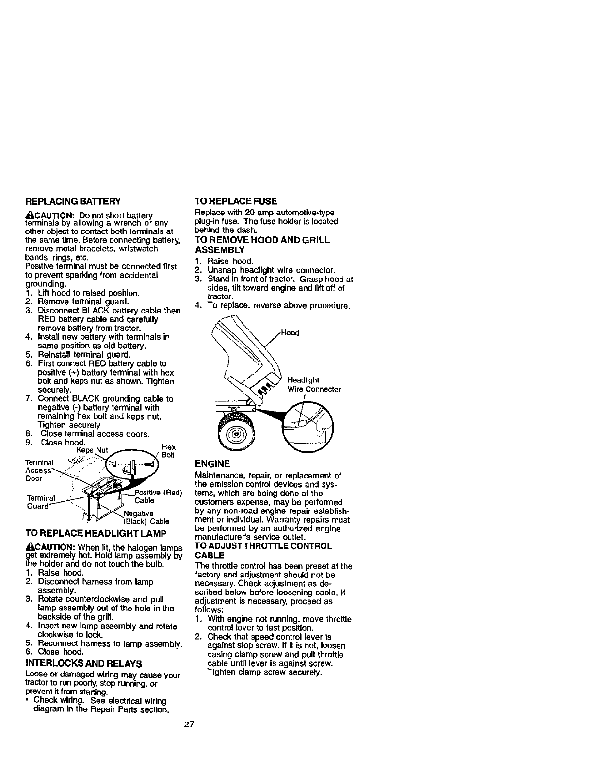
REPLACING BA'rrERY
ACAUTION: Do not short battery
terminals by allowing a wrench or any
other object to contact both terminals at
the same time. Before connecting battery,
remove metal bracelets, wristwatch
bands, rings,etc.
Positiveterminal must be connected first
to prevent sparkingfrom accidental
grounding.
t. Lifthoodto raised position.
2. Remove terminal guard.
3. Disconnect BLACK battery cable then
RED battery cable and carefully
removebattery fromtractor.
4. Install new battery with terminals in
same positionas old battery,
5. Reinstall terminal guard.
6. First connect RED battery cableto
positive (+) battery terminal with hex
boltand keps nut as shown. Tighten
securely.
7. Connect BLACK grounding cable to
negative (-) batteryterminal with
remaining hex bolt and keps nut.
Tighten securely
8, Close terminal access doors.
9. Close hood. Hex
KepsNut _ / Bo_1
Door _
." _Positive (Red)
Terminal_ _L _Cable
TO REPLACE HEADLIGHT LAMP
_CAUTION: When lit the halogen lamps
get extremely hot.He d amp assembly Dy
the holder and do not touch the bulb.
1. Raise hood.
2. Disconnect harness from lamp
assembly.
3. Rotate counterclockwise and pull
lamp assembly out ofthe hole in the
backside of the grill.
4. Insert new lamp assembly and rotate
clockwise to look.
5. Reconnect harness to lamp assembly.
6. Close hood.
INTERLOCKS AND RELAYS
Looseor damaged wiringmay cause your
tractorto run poody, stop running,or
preventit from starting.
• Check widng. See electrical wiring
diagram in the Repair Parts section.
27
TO REPLACE FUSE
Replace with 20 amp automotive.type
plug-in fuse. The fuse holder is located
behind the dash.
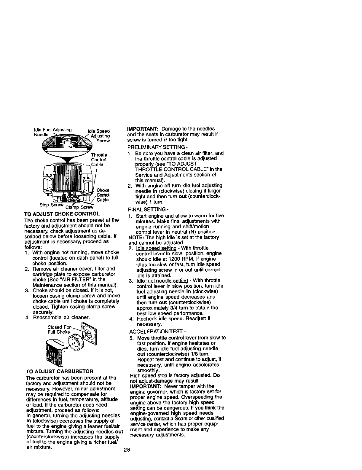
TO REMOVE HOOD AND GRILL
ASSEMBLY
1. Raise hood.
2. Unsnap headlight wire connector.
3. Stand infront oftractor. Grasp hoodat
sides, tilttoward engine and liftoff of
tractor.
4. To replace, reverse above procedure,
)
Headlight
WireConnector
ENGINE
Maintenance, repair, or replacement of
the emission contml devices end sys-
tems, which are being done at the
customers expense, may be performed
by any non-road engine repair establish-
ment or individual.Warranty repairs must
be performed by an authorized engine
manufacturer's service outlet.
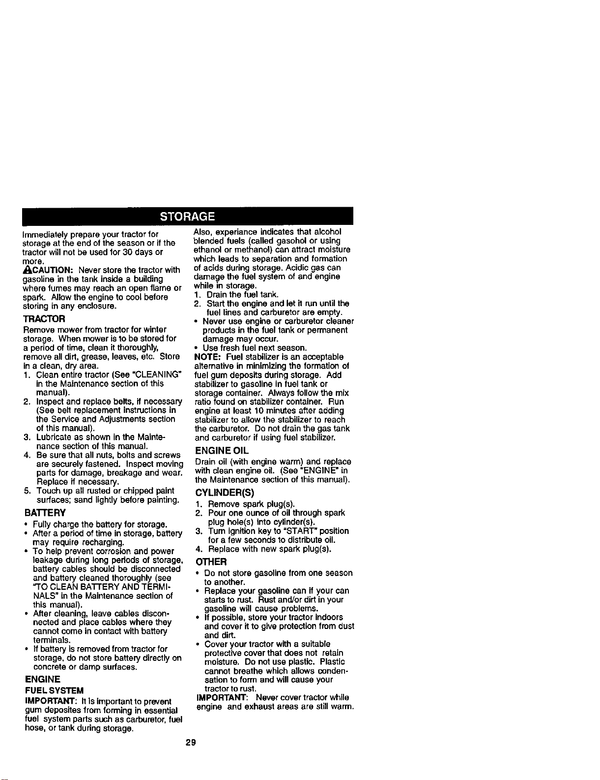
TO ADJUST THRO'I'rLE CONTROL
CABLE
The throttlecontrol has been preset at the
factory and adjustment should not be
necessary. Check adjustment as de-
scribed below before loosening cable. If
adjustment is necessary, proceed as
follows:
1. With engine not running, move throttle
control leverto fast position.
2. Check that speed control lever is
against stop screw. If itis not, loosen
casing clamp screw and pull throttle
cable until lever is against screw.
Tighten clamp screw securely.
Idle Fuel Adjusting Idle Speed
Needle Adjusting
Screw
Throttle
Control
3hoke
/ Cm'rol
Cable
Screw
TO ADJUST CHOKE CONTROL
The choke control has been preset at the
factory and adjustment should not be
necessary, check adjustment as de-
scribed below before loosening cable. If
adjustment is necessary, proceed as
follows:
1. With engine not running, move choke
cantrol (located on dash panel} to full
choke position.
2. Remove air cleaner cover, filter and
cartridge plate to expose carburetor
choke (See "AIR FILTER" in the
Maintenance section of this manual}.
3. Choke should be closed. If it is not,
loosen casing clamp screw and move
choke cable untilchoke is completely
closed. Tighten casing clamp screw
securely.
4. Reassemble air cleaner.
Full Choke
TO ADJUST CARBURETOR
The carburetor has been present at the
factory and adjustment should not be
necessary. However, minor adjustment
may be required to compensate for
differences in fuel, temperature, altitude
or load. If the carburetor does need
adjustment, proceed as follows:
In general, turning the adjusting needles
In (clockwise) decreases the supplyof
fuel to the engine givinga leaner fuel/air
mixture. Turningthe adjusting needles out
(counterclockwise)increases the supply
of fuel to the engine giving a richer fuel/
IMPORTANT: Damage to the needles
and the seats in carburetor may result if
screw is turned in too tight.
PRELIMINARY SETI'IN G -
1. Be sure you have a clean air filter, and
the throttle control cable is adjusted
properly (see "TO ADJUST
THRO'I-rLE CONTROL CABLE" inthe
Service and Adjustments section of
this manual).
2. With engine off tum idle fuel adjusting
needle In (clockwise) closing if finger
tight and then turn out (countemlock-
wise} 1turn.
FINAL SE'r-rlNG -
1. Start engine and allow to warm forfive
minutes. Make final adjustments with
engine running and shiWmotion
control lever in neutral (N) position.
NOTE: The high idle is set at the factory
and cannot be adjusted.
2. Idle soeed settina - With throttle
control lever in slow position, engine
should idle at 1200 RPM. If engine
idles too slow or fast, tam idle speed
adjustingscrew in or out untilcorrect
idle is attained.
3. Idle fuel needle settine - With throttle
control lever in slow position, turn idle
fuel adjusting needle In (clockwise)
until engine speed decreases and
then tam out (countemlockwise)
approximately 3/4 tam to obtain the
best low speed performance.
4. Recheck idle speed. Readjust if
necessary.
ACCELERATION TEST -
5. Move throttle controllever from slow to
fast position, If engine hesitates or
dies, tum idle fuel adjusting needle
out (counterclockwise) 1/8 turn.
Repeat test and continue to adjust, if
necessary, until engine accelerates
smoothly.
High speed stopis factory adjusted. Do
not adjust-damage may result.
IMPORTANT: Never tamper with the
engine governor,which is factory set for
proper engine speed. Overspeeding the
engine above the factory high speed
setting can be dangerous. If you think the
engine-govemed high speed needs
adjusting, cordacta Sears orotherqualified
service center, which has proper equip-
ment and expedanca to make any
necessary adjustments.
air mixture.
28
Immediately prepare your tractorfor
storage at the end of the season or if the
tractor will not be used for 30 days or
more.
ACAUTION: Never store the tractor with
gasoline in the tank inside a building
where fumes may reach an open flame or
spark. Allow the engine to cool before
storing in any enclosure.
TRACTOR
Remove mower from tractor for winter
storage. When mower is to be stored for
a period of time, clean it thoroughly,
remove all dirt, grease, leaves, etc. Store
in a clean, dry area.
1. Clean entire tractor (See "CLEANING"
in the Maintenance section of this
manual).
2. Inspect and replace belts, if necessary
(See belt replacement instructions in
the Service and Adjustments section
of this manual).
3. Lubricate as shown in the Mainte-
nance section of this manual.
4. Be sure that all nuts, bolts and screws
are securely fastened. Inspect moving
parts for damage, breakage and wear.
Replace if necessary.
5. Touch up aUrusted or chipped paint
surfaces; sand lightly before painting.
BATI'ERY
• Fully charge the battery for storage.
• After a period of time in storage, battery
may require recharging.
• To help prevent corrosion and power
leakage during long periods of storage,
battery cables should be disconnected
and battery cleaned thoroughly (see
"ro CLEAN BA'R'ERY AND TERMI-
NALS" in the Maintenance section of
this manual).
• After cleaning, leave cables discon-
nected and place cables where they
cannot come in contact with battery
terminals.
• If battery is removed from tractor for
storage, do not store battery directly on
concrete or clampsurfaces.
ENGINE
FUEL SYSTEM
IMPORTANT: It isimportantto prevent
gum deposites from forming in essential
fuel system parts such as carburetor,fuel
hose, or tank dudng storage.
Also, expedance indicates that alcohol
blended fuels (called gasohol or using
ethanol or methanol) can attract moisture
which leads to separation and formation
of acids during storage. Acidic gas can
damage the fuel system of and engine
while in storage.
1. Drain the fuel tank.
2. Start the engine and let it run untilthe
fuel lines and carburetor are empty.
• Never usa engine or carburetor cleaner
products in the fuel tank or permanent
damage may occur.
• Use fresh fuel next season.
NOTE: Fuel stabilizer is an acceptable
alternative in minimizing the formation of
fuel gum deposits dudngstorage. Add
stabilizerto gasoline in fuel tank or
storage container. Always followthe mix
ratio found on stabilizer container. Run
engine at least 10 minutes after adding
stabilizer to allow the stabilizer to reach
the carburetor. Do not drain the gas tank
and carburetor if usingfuel stabilizer.
ENGINE OIL
Drain oil (with engine warm) and replace
with clean engine oil. (See "ENGINE" in
the Maintenance section of this manual).
CYLINDER(S)
1. Remove spark plug(s).
2. Pour one ounce of oil through spark
plug hole(s) into cylinder(s).
3. Turn ignitionkey to "START" position
for a few seconds to distributeoil.
4. Replace with new spark plug(s).
OTHER
• Do not store gasoline from one season
to another.
• Replace your gasoline can if your can
startsto rust. Rust and/or dirt in your
gasoline will cause problems.
• If possible, store your tractor indoors
and cover it to give protectionfmm dust
and dirt.
• Cover your tractor with a suitable
protective cover that does not retain
moisture. Do not use plastic. Plastic
cannot breathe which allows conden-
sation to form and will cause your
tractorto rust.
IMPORTANT: Never cover tractor while
engine and exhaust areas are stillwarm.
29
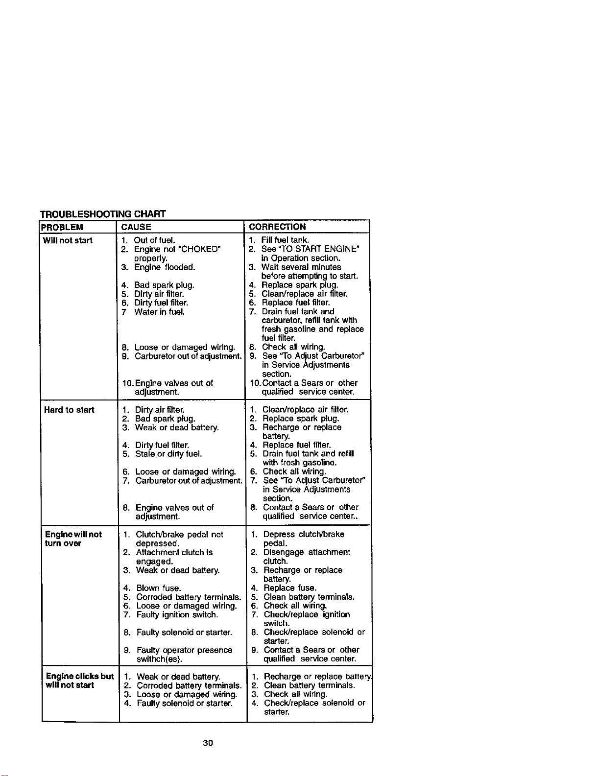
TROUBLESHOOTINGCHART
PROBLEM CAUSE
Will not start 1. Out offuel.
2. Engine not "CHOKED"
properly,
Herd to start
Englnewilinot
turn over
3. Engine flooded.
4, Bad spark plug.
5. Dirty air filter.
6. Dirty fuel filter.
7 Water in fuel.
8. Loose or damaged widng.
9. Carburetor out ofadjustment.
10.Engine valves out of
adjustment.
1. Dirty air filter,
2. Bad spark plug.
3. Weak or dead battery.
4. Dirty fuel filter.
5. Stale or dirtyfuel.
6. Loose or damaged wiring.
7. Carburetor outof adjustment.
8.
Enginevalves outof
adjustment.
1. Clutch/brake pedal not
depressed.
2. Attachment clutchis
engaged.
3. Weak or dead battery.
4. Blown fuse.
5. Corroded battery terminals.
6. Loose or damaged widng.
7. Faulty ignition switch.
8. Faulty solenoid or starter.
9.
CORRECTION
1. Fill fuel tank.
2. See"TO START ENGINE"
in Operation section.
3. Wait several minutes
before attempting to start.
4, Replace spark plug.
5. Clean/replace air filter.
6. Replace fuel filter.
7. Drain fuel tank and
carburetor, refill tank with
fresh gasoline and replace
fuel filter.
8. Check all widng.
9. See "To Adjust Carburetor"
in Service Adjustments
section.
1O.Contact a Sears or other
qualified service center.
1. Clean/replace air filter.
2. Replace spark plug.
3. Recharge or replace
battery.
4. Replace fuel filter.
5. Drain fuel tank and refill
with fresh gasoline.
6. Check all wiring.
7. See "To Adjust Carburetor"
in Service Adjustments
section.
8. Contact a Sears or other
qualified service center..
1. Depress clutch/brake
pedal.
2. Disengage attachment
clutch.
3. Recharge or replace
battery.
4. Replace fuse.
5. Clean battery terminals.
6. Check all widng.
7. Check/replace ignition
switch.
8. Check/replace solenoid or
starter.
9. Contact a Sears or other
qualified service center.
Faulty operator presence
swithch(es).
Engine clicks but 1. Weak or dead battery. 1. Recharge or replace batter
will not start 2. Corroded battery terminals. 2. Clean battery terminals.
3. Loose or damaged widng. 3. Check all widng.
4. Faulty solenoid or starter. 4. Check/replace solenoid or
starter.
30
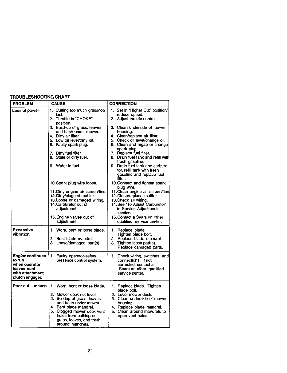
TROUBLESHOOTING CHART
PROBLEM CAUSE
Lossofpowar 1. C_ingtoo mu_ gms_oo
Excessive
vibr_ion
Engine continues
to run
when operator
leaves seat
with attachment
clutch engaged
Poorcut-uneven
fast.
2. Throttle in "CHOKE"
position.
3. Build-up of grass, leaves
and trash under mower.
4. Dirty air filter.
5. Low oil level/dirty oil.
6. Faulty spark plug.
7. Dirtyfuel fiifer.
8. Stale or dirty fuel.
9. Water in fuel.
10.Spark plug wire loose,
11.Dirty engine air screen/fins.
12.Dirty/clogged muffler.
13.Loose or damaged wiring.
14.Carburetor out of
adjustment.
15.Engine valves out of
adjustment.
1. Wom, bent or loose blade.
2. Bent blade mandrel.
3. Loose/damaged part(s).
1. Faulty operator-safety
presence control system.
1. Worn, bent or loose blade.
2. Mower deck not level.
3. Buildup of grass, leaves,
and trash under mower.
4. Bent blade mandrel.
5. Clogged mower deck vent
holes from buildupof
grass, leaves, and trash
around mandrels.
CORRECTION
1. Set in "Higher Cut" position/
reduce speed.
2. Adjust throttlecontrol.
3. Clean underside of mower
housing.
4. Clean/replace air filter.
5. Check oil !evel/change oil.
6. Clean and regap or change
spark plug.
7. Replace fuel filter.
8. Drain fuel tank and refill wltl
fresh gasoline.
9. Drain fuel tank and carbure.
tar, refilltank with fresh
gasoline and replace fuel
filter.
10.Connect and tighten spark
plug wire.
11.Clean engine air ecreenifin,,
12. Clean/replace muffler.
13.Check all wiring.
14.Sea "To Adjust Carburetor"
in Service Adjustments
section.
15.Contact a Sears or other
qualified service center.
1. Replace blade.
Tighten blade bolt.
2. Replace blade mandrel.
3. Tighten loose part(s).
Replace damaged parts.
1. Check wiring, switches ant
connections. If not
corrected, contact a
Sears or other qualified
service center.
1. Replace blade. Tighten
blade bolt.
2. Level mower deck.
3. Clean underside of mower
housing.
4. Replace blade mandrel.
5. Clean around mandrels to
open vent holes.
31
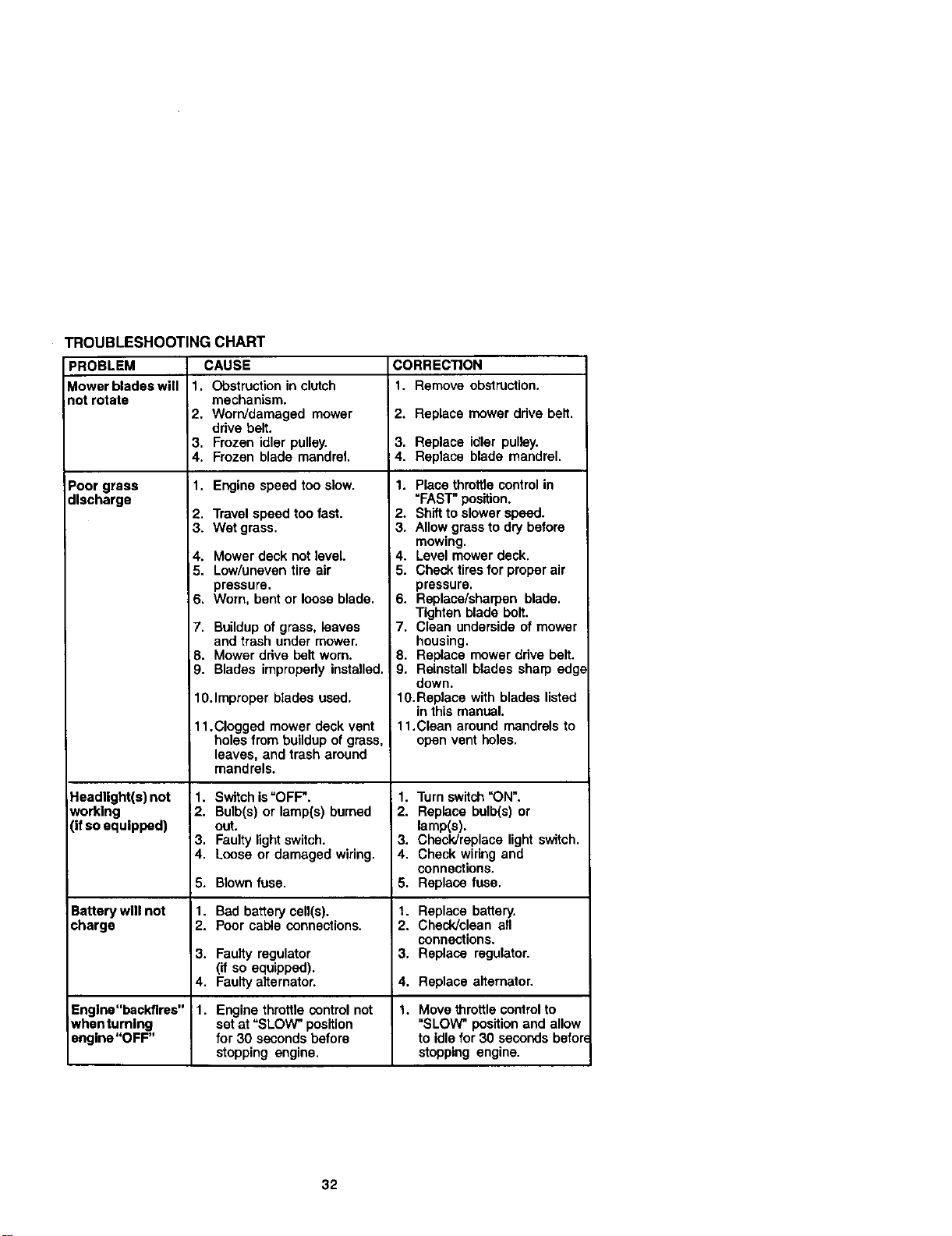
TROUBLESHOOTINGCHART
PROBLEM CAUSE CORRECTION
Mowerbladeswill 1. Obstructioninclutch 1. Removeobstruction.
notrotate mechanism.
2. Worn/damaged mower 2. Replace mower drive belt,
drive belt.
3. Frozen idler pulley. 3. Replace idler pulley.
4. Frozen blade mandrel. 4. Replace blade mandrel.
Poor grass 1. Engine speed too slow.
discharge
2, Travel speed too fast.
3. Wet grass.
4. Mower deck not level.
15. Low/uneven tire air
pressure.
6. Worn, bent or loose blade.
7. Buildup of grass, leaves
and trash under mower.
8. Mower drive belt worn.
9. Blades impropedy installed.
10.Improper blades used.
11.Clogged mower deck vent
holes from buildup of grass,
leaves, and trash around
mandrels.
1. Place throttlecontrol in
"FAST" position.
2. Shiftto slower speed.
3. Allow grassto dry before
mowing.
4. Level mower deck.
5. Check tires for proper air
pressure.
6. Replace/sharpen blade.
Tighten blade bolt.
7. Clean underside of mower
housing.
8. Replace mower drive belt.
9. Reinstall blades sharp edg(
down.
10.Replace with blades listed
in this manual.
11.Clean around mandrels to
open vent holes.
Headlight(a) not 1. Switch is"OFF". 1. Turn switch=ON".
working 2. Bulb(s) or lamp(s) burned 2. Replace bulb(s) or
(ifso equipped) out. lamp(s).
3. Faulty lightswitch. 3. Check/replace light switch.
4. Loose or damaged wiring. 4. Check wiring and
connections.
5. Blown fuse. 5. Replace fuse.
Battery wlll not 1. Bad battery cell(s), t. Replace battery.
charge 2. Poor cable connections. 2. Check]clean all
connections.
3. Faulty regulator 3. Replace regulator.
(if so equipped).
4. Faulty alternator. 4. Replace alternator.
Engine"backfires" 1. Engine throttle control not 1. Move throttle control to
whenturnlng set at "SLOW" position "SLOW" position and allow
angine"OFF" for 30 seconds before to idle for 30 seconds befor
stopping engine, stopping engine.
32
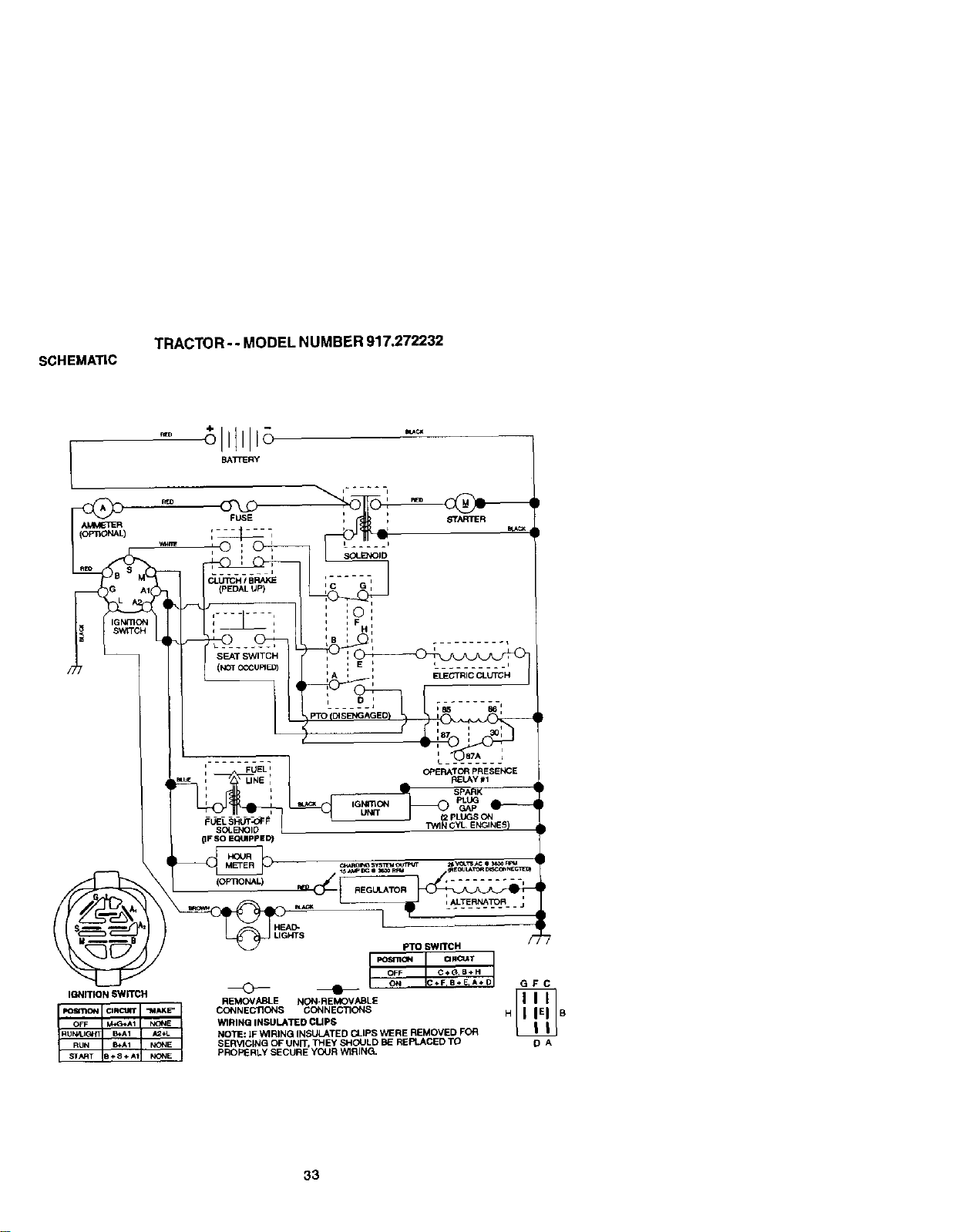
SCHEMATIC
TRACTOR - - MODEL NUMBER 917.272232
I
AMM_'_ER
FUSE
i I
....... J
Ct.UTCH / BRAKE
(PEDAL UP)
r
SEAT SWITCH
(NOT cCCUF_ED)
C G I
:©'
I i
: :F
_B , ..........
)
, E _ , _1
, A , , EL_EGTRICCLUTCH
D I .
...... J _85 p_l,
PTO (DIS
I i
' : 30
[ _._) OTA L
OPERATOR PRESENCE
REI.AY #1
SPARK
UNIT
pLUGS ON
TV_IN GYL ENGINES)
IGNITION SWITCH
OFF _AI N(_IE
ST,_T 0÷8+AI NONE
RUN_tI_h'T _A1 _2_L
RUN Eu_A1 NIXIE
HEAD*
UGHTS
REMOVABLE NON*REMOVABLE
CONNECTIONS CONNECTIONS
'/_1RINQ INSULATED CUPS
NOTE: IF WIRINQ INSULATED CLIPS WERE REMOVED FOR
SERVICING OF UNIT, THEY SHOULD BE REPLACED TO
PROPERLY SECURE YOUR WIRING.
GFC
DA
33

ELECTRICAL
TRACTOR - - MODEL NUMBER 917.272232
8O
34

ELECTRICAL
TRACTOR - - MODEL NUMBER 917.272232
KEY PART
NO. NO, DESCRIPTION
1
2
8
10
11
12
15
21
24
25
26
27
28
29
3O
33
4O
45
46
5O
55
79
81
9O
91
82
93
NOTE:
163465 Battery
74760412 BoB,Hex 1/4.20 x _4
7603,1 Tray, Battery
145211 Bolt, Btr Front 1/4-20 x 7-1/2
150109 Holddewn BatteW Front Mount
145769 Nut, Push Nylon Battery Front 1/4
153664 Switch Interlock Push-In
175449 Harness, Ught
8860R Cable, Battery
146148 Cable, Battery
175158 Fu_e
73510400 Nut Keps Hex 1/4-20 UNC
145491 Cable, Ground
160784 Switch, Seat
175442 Switch, Ignition
175447 Key,Molded, Craftsman
178451 Harness, Ignition
175548 Ammeter 15Amp
175549 Hourmeter Snap-In
178461 Switch Pto 3 Pdt Red Delta
17490508 Screw Tndml 5/16-16 x 1/2
175448 Lamp Assembly
109748X Relay ASm
176717 Clamp Bacl<Amp Gauge
176730 Washer LockAmp Gauge
176733 Nut
176732 _arnp Hourmetm
All component dimensions given In U.S, inches
1 Inch = 25.4 mm
35
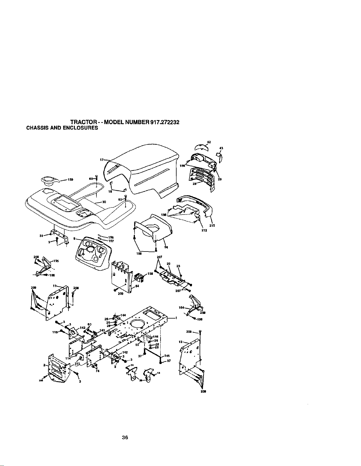
TRACTOR - - MODEL NUMBER 917.272232
CHASSISAND ENCLOSURES
42
29
21S
212
168
36
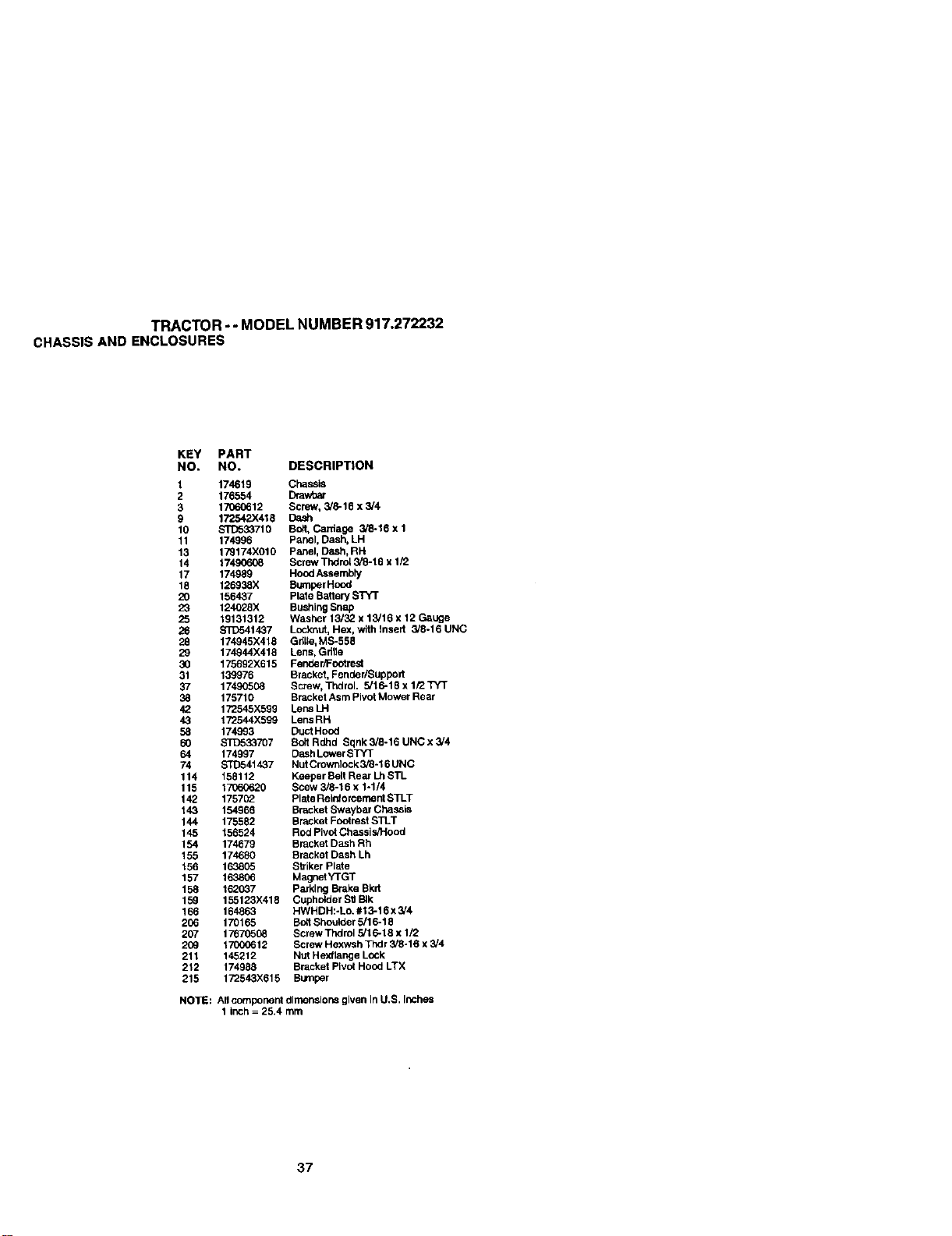
TRACTOR - - MODEL NUMBER 917.272232
CHASSISAND ENCLOSURES
KEY PART
NO, NO. DESCRIPTION
1 174619 Chassis
2 178554 Drawhar
3 17060612 Screw, 3/8-18 x 3/4
9 172542X418 Dash
10 ST[To33710 BOR,Cardage 3/8-18 x 1
11 174996 Panel, Dash, LH
13 179174X010 Panel, Dash, RH
14 17_ Screw Thdm[ 3/8-18 x 1/2
17 174989 HOOdAssembly
18 126938X Bumper Hood
20 156437 Plale Battery S]_¢T
23 124(Y28X BushingSnap
25 19131312 Washer 13/32 x 13/18 x 12 Gauge
26 $3_541437 Locknut, Hex, with Insert 3/8-16 UNC
28 174945X418 Gd_le,MS-558
29 174944X418 Lens, Gdfle
30 175892X615 Fende r/_,=ootrest
31 139976 Bracket, Fender/Support
37 17490508 Screw, Thdrol. 5/16-18 x 1/2 TYT
38 175710 Bracket Asm Pivot Mower Rear
42 172545)(599 Lens LH
43 172544X599 Lens RH
58 174993 Duct Hood
60 STD533707 Bo_t Rdhd Sqnk 3/8-16 UNC x 3/4
64 174997 Dash LowerSrl'T
74 STD541437 NutCrownlock3/8-16 UNC
114 158112 Keeper Bert Rear Lh STL
115 17060620 Scew 3/8-16 x 1-1/4
142 175702 Plate Relnforcemerd STLT
143 154968 Bracket Swa,ybar Chassis
144 175582 Bracket FootrestSTLT
145 158524 Rod Pivot ChasslsJHood
154 174679 Bracket Dash Rh
155 174680 Bracket Dash Lh
156 163805 Striker Plate
157 163806 Magrmt YrGT
158 162037 Parking Brake Bkrt
15_ 155123X418 Cupholder Stl BIk
166 164863 HWHDH:-Lo. #13-16 x 3/4
206 170168 BoltShoulder 8/16-18
207 17670508 Screw Thdrol 5/16-18 x 1/2
209 1_12 Screw Hexwsh Thdr 3/8-16 x 3/4
211 145212 Nut Hexllange Lock
212 174988 Bracket Pivot Hood LTX
215 172543X818 Bumper
NO'IE: All component dimensions given In U.S. Inches
1 inch = 25.4 mm
37
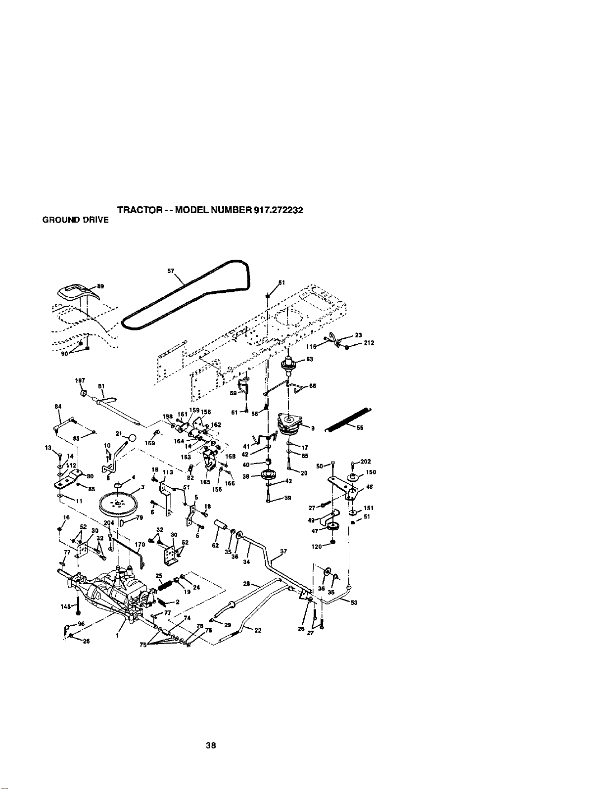
TRACTOR - - MODEL NUMBER 917.272232
GROUNDDRIVE
57
38
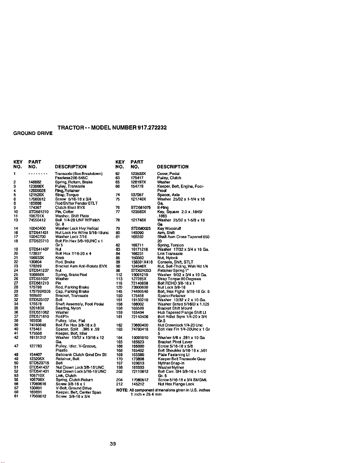
TRACTOR -- MODEL NUMBER 917.272232
GROUND DRIVE
KEY PART KEY PART
NO. NO. DESCRIPTION NO. NO. DESCRIPTION
2
3
4
5
6
8
g
10
11
13
14
t6
17
18
19
2O
21
22
23
24
25
26
27
28
29
3O
34
35
36
37
38
39
4O
41
42
47
48
49
5O
51
52
53
55
56
57
59
61
Trarksaxle(See Breakdown) 62 123533X Cover, Pedal
Peehess25o-54oC 63 175417 Pulley, Clutch
146682 Spring, Retain, Brake 65 126167X Washer
123666X pulley, Transaxle 66 154?78 Keeper, Belt, Engine, Fool-
12000028 Ring,Retainer Proof
121520X Sft_o, Torque 74 137057 Spacer, Axte
17060512 Screw 5/16-18x3/4 75 121749X WaSher 25/32x 1-1/4x16
165866 Red Shifter Fender STLT Ga.
174367 Clutch Elect EVX 76 STD581075 E-Ring
STC561210 Pin, Cotter 77 123583X Key, Square 2.0 x .1845/
105701X Washer, Shift Plate .1865
74550412 Bolt 1/4-28 UNF W/Patch 78 12174OX Washer 25/32 x 1-5/8 x 16
Gr. 8 Ga
10040400 Washer Loak Hvy He]lcai 79 STD580(_5 Key Woodnlff
ST]_5414Ol Nut Lock Hx Wllns 5/16-18unc 80 145090 Arm, ShWi
10040700 Washer Lock 7/16 81 165592 Sheft Asm Cross Tapered 650
STD523710 Bolt FinHex 3/8-16UNC x 1 20
Gr5 8_ 165711 Spdng,Torsion
STD541437" Nut 83 19171216 Washer 17132 x 3/4 x 16 Ga.
173937 Bolt Hex 7/16-20 x 4 84 166231 Unk TraJlsaxle
106933X Knob 65 150360 Nut, N/lock
130804 Red, Srake 89 15O391X418 Console, Shilt, STLT
178269 BraCketAsm Anti*Rotate EVX 90 124O46X Nut. SaifoThding, Wsh Hd 1/4
STD541237 Nut 86 $3D624O03 Retainer Spdng 1"
1_o888X Spitng, Brake Red 112 19091210 Washer 9/32 x 3/4 x 10 Ga.
STC5515O7 Washer 113 127285X Strap Torque 90 Degrees
S_:)561210 Pin 116 72140608 Bo9RDHD 5/6-16 x 1
175798 Rod, Parking Brake 120 73900600 NUt Lock 3,/8-16
175799X505 Cap, parking Brake 145 74490540 Bo!t,Hex Flghd 5/16-16 Gr. 5
169592 Sracket, Transaxle 150 175456 Spacer Retalner
ST[_2OlO7 Solt 151 19133210 Washer 13/32 x 2 x 10 Ga_
175578 Shaft/_sembly, Foot Pedal 156 166002 Washer Srfted 5/161D x 1.125
120183X Bearing, Nylon 158 165589 Bracket Shift Mount
$3_551062 Washer 159 165494 Hub Tapered Flange Shitt U
S'1D571810 RolIPIn 161 72140406 Bett Rdhd Sqnk 1/4-20 x 5/4
165936 Pulley, Idler, Flat Gr.5
74760648 Bolt Fin Hex 3/6-16 x 3 102 73680400 NutCrownlock 1/4-20 Unc
175461 Spacer, Split .395 x .59 163 74780416 Bolt Hex Fin 1/4-20Unc x 1 Gr
175556 Keeper, Belt, Idler 5
19131312 Washer 13/32 x 13/16 x 12 164 19091010 Washer 5!8 x .281 x 10 Ga
Ga_ 165 165623 Bracket Pivot Lever
127783 Pulley, Idler, V-Groovn, 166 166880 Screw 5/16-18 x 5/8
Plastic 168 165492 Bo6 Shoulder 5/16-18 x .561
154407 Bellcrank Clutch Grad Dry Stl 169 165580 Plale Fastening Lt
123205X Retainer, Bait 170 1_ Keeper Belt Transaxte Gear
STD52O715 Bolt 197 169613 NyllnerSnap-In
$1_541437 Nut Crown Lock3/8-16 UNC 198 169593 Washer Nyliner
STD5414Ol Nut Crown Lock5/16-18 UNC 202 72110612 Bett Carr. SH 3/6-16 x 1°1/2
105710X Link, Clutch Gr. 5
10570_X Spdng, Clutch Return 204 17060512 Screw 5/16-18 x 3/4 SMGML
1706_i16 Screw 3/6-16 x 1 212 145212 NUt Hex Flange Lock
130801 V-Bait, Ground Drive NOTE: All component dimensions given in U.S. Inch_
169691 Keeper, Belt, Center Span 1 Inch = 25.4 rnm
17060612 Screw 3/3-16 x 3/4
39
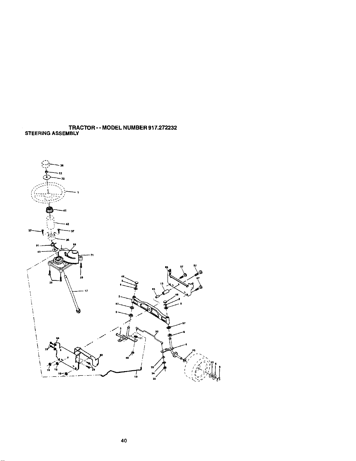
TRACTOR -- MODEL NUMBER 917.272232
STEERINGASSEMBLY
4O

TRACTOR - - MODEL NUMBER 917.272232
STEERINGASSEMBLY
KEY PART
NO. NO. DESCRIPTION
1 175139X418 Steering Wheel
2 172393 Axle Assembly Cast Iron
3 169840 Spind/e Assembly, LH.
4 169839 Spindle Assembly, R.H.
5 6261_H Bearing, Race, Thrust, Hardened
6 121748X Washer 25/32 x 1-5/8 x 16 Gauge
6 12000029 Ring, Klip
10 175121 Dr_k
11 10040600 Washar Lock 3/8
12 73940800 Nut Hex Jam Toplock 1/2-20 Unf
13 136516 Spacer Brg Axle Front
15 145212 Nut Hexflange Lock
17 177883 Shaft Assembly, Steering
29 17060612 Screw, 3/8-16 x 3/4
3_ 170162 Rod,T_e
33 19111216 Washer 11/22 x 3/4 x 16 Ga/
34 $1_551131 Washer Lock Hvy Spr. 5/16
36 73540500 Locknut 5/16-24 Unt
36 155105 Bushing, Steering
37 152927 Screw
38 175140X416 Ir_sed,Steering Wheel
40 _1537 Gdpco Nut
41 159945 Adaptor, Steedng Wheel
42 174530X416 Boot, Steedng Shaft
43 121749X Washer 25/32 x 1-1/4 x 16 Gauge
46 121232X Cap, Spindle
65 160367 Spacer Brace Axle
67 72140618 BoltRdnd Sq 3_B-16 UNC x 2-1/4
68 169827 Axle, Brace
71 175146 Steering Asm.
72 19182411 Washer 9/16 Id x 1-1/20d 11 G Zln
82 169835 Bracket Susp Chassis Front
87 173966 Washer Flat .781 x 1 1/2x .14
88 175118 Bolt Shoulder 7/16-20
91 175553 Cl_pSteedng
NO'rE: All component dtrnensiol_sgiven in U.S. inches
1 inch = 25.4 mrn
41
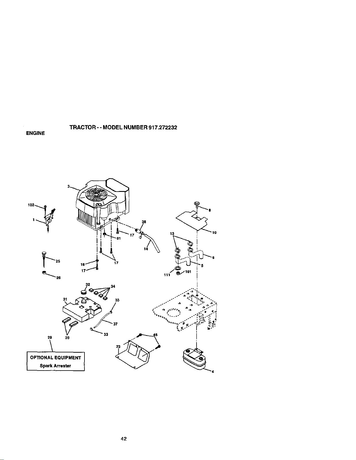
ENGINE
TRACTOR - - MODEL NUMBER 917.272232
25 17
16
1
32 ,34
2i39
OPTIONAL EQUIPMENT I
Spark Arrester
42
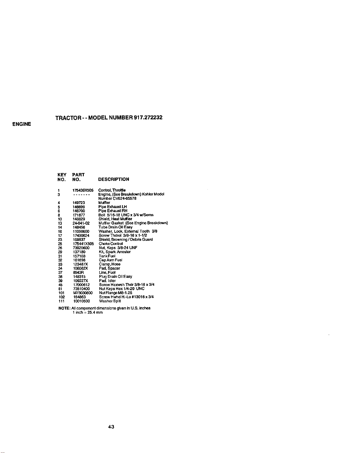
ENGINE
TRACTOR - - MODEL NUMBER 917.272232
KEY PART
NO. NO. DESCRIPTION
175439X505 ControI,Thml6e
....... Engine, (See Bre_ctown) Kohler Model
Number CV624-65578
4 149723 Muffler
5 146699 Pipe Exhaust LH
6 146700 Pipe E_aust RH
8 171877 Bolt 5/16-16 UNC x 3/4w/Seres
10 146629 Shield, Heat Muffler
13 24-O41-02 Muffler Gasket (See Engine Breakdown)
14 148456 Tube Drain OilE_wy
16 11050600 Washer, Lock, ExtemaJ Tooth 3/8
17 17490624 Screw Thdml 3/8-16 x 1-1/2
23 169837 Shield, Browning / Debds Guard
25 175441X505 Cheke Conbol
26 73920600 Nut, Keps 3/6-24 UNF
29 137160 Kit, Spark Arrestor
31 157103 TankFLml
32 161696 Cap Asm Fuel
33 123487X Clamp,Hose
34 106082X Pad, Spacer
37 8543R Line, Fuel
38 148315 Plug Drain Oil Easy
39 10_227X Pad, Idler
45 170_12 Screw Hexwsh Thdr 3/6-16 x 3/4
61 73510400 Nut Keps Hex 1/4-20 UNC
101 M73030800 Nut Flange M8-1.25
102 164863 Screw Hwhd H.-Lo #13016 x 3/4
111 10010500 Washer Split
NOTE: All component dimensions given inU.S. inches
1 inch = 25.4 mm
43
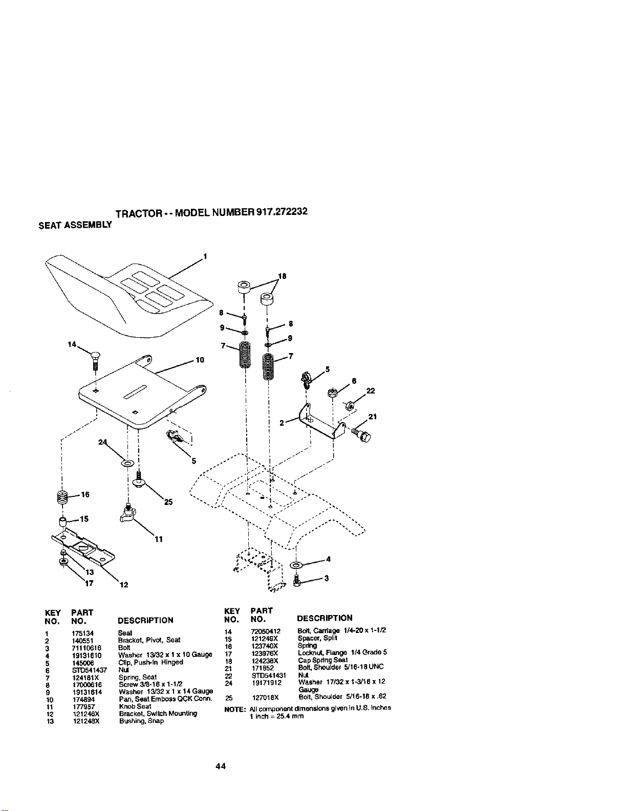
TRACTOR - - MODEL NUMBER 917,272232
SEATASSEMBLY
KEY PART KEY PART
NO. NO. DESCRIPTION NO. NO. DESCRIPTION
1 175134 Seat 14 72050412 Bolt, Carriage 1/4-20 x 1-1/2
2 140551 Bracket, Pivot, Seat 15 121249X Spacer, Split
3 71110616 Bolt 16 123740X Spring
4 19131610 Washer 13/32 x 1 x 10 Gauge 17 123976X Locknt_. Flange 1/4 C-rsde 5
5 145006 Clip, push-In Hinged 18 124238X Cap Spring Seat
6 s'rD541437 Nut 21 171852 Bolt, Shoulder 5/10-18 UNC
7 124181X Spring, Seat 22 STD541431 Nul
8 17000616 Screw 3_-16 x 1-1/2 24 19171912 Washer 17/32 x 1-3/16 x 12
9 19131614 Washer 13/32 x 1 x 14 Gauge Gauge
10 174894 pan, Seat Emboss QCK Conn. 25 127018X Bolt, Sho_der 5/16-18 x .62
11 177957 Knob Seat NOTE: All ccrnpo_ent dimensions given _nU,S. tnches
12 121246X Bracket, Switch Mounttng 1 inch = 25.4 turn
13 121248X Brushing,Snap
44
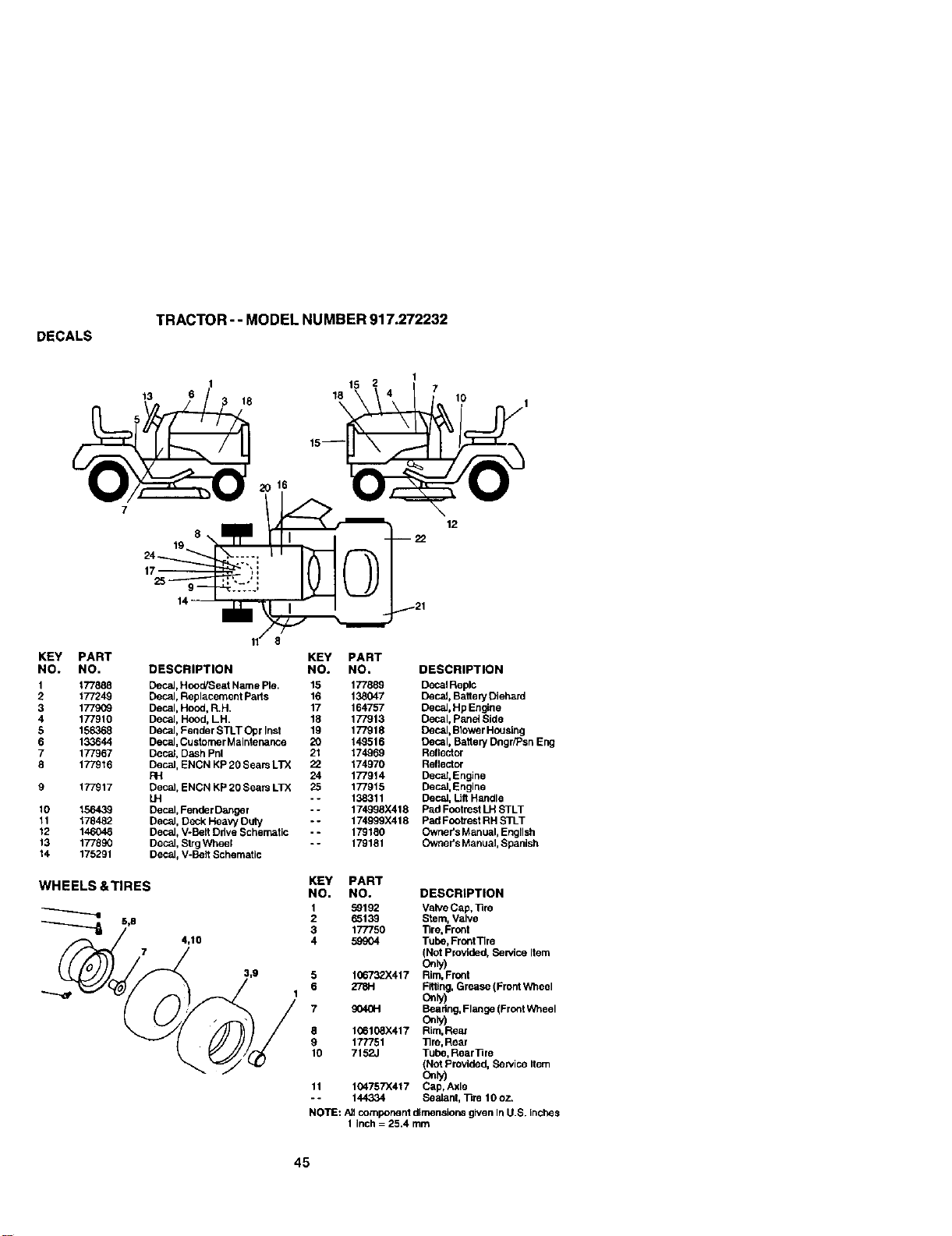
DECALS
TRACTOR-- MODEL NUMBER 917.272232
13
18
15
18
\
1
7
lO
8
24_
12
KEY PART
NO. NO.
1 177888
2 177249
3 177909
4 177910
5 156368
6 133644
7 177967
8 177916
9 177917
10 156439
11 178482
12 146046
13 177890
14 175291
WHEELS &TIRES
5,8
DESCRIPTION
DecaJ,HooWSeat Name Pie.
Decal, Replacement Fads
Decal, Hood, R.H.
Decal, Hood, LH.
Decal, Fender STLT Opr Inef
Decal, Custorner Maintenance
Decal, Dash Phi
DecaJ, ENCN KP 20 Seam LTX
FH
Decal, ENCN KP 20 Sears LTX
LH
Decal, Fender Danger
Decal, Deck HeaW Duty
Decal, V-Belt Drive Schematic
Decal, Strg Wheel
Decal, V-Belt Schematic
4,10
KEY PART
NO. NO. DESCRIPTION
15 177889 DecalReplc
16 138047 Decef, Battery Diehard
17 164757 Decal, Hp Engine
18 177913 Decal, Panel Side
19 177918 Decal, Blower Houalng
20 149516 Decal, Battery Dngr/Psn Eng
21 174969 Reflector
2_ 174970 Reflector
24 177914 Deca[, Engine
25 177915 Decef, Engine
- - 138311 Decal, Lift Handle
- - 174998X418 Pad Foolrest LH STLT
-- 174999)<418 Pad Footrest RH STLT
-- 179180 Owner's Manuef, English
-- 179181 Owner's Manual, Spanish
KEY PART
NO. NO. DESCRIPTION
1 S_192 Valve Cap, ]3re
2 65139 Stem, Valve
3 177750 Tire, Front
4 59904 Tuhe,FrontTire
(Not Provided, Service Item
Only)
5 106732X417 Rim,Front
6 2781-1 Fitting,Grease (Front Wheel
1 Only)
7 904GH Bealtng, Flange (Front Wheel
On_
8 1Q6108X417 Rim,Rear
9 177751 Tim, Rear
10 7152J Tube, RearTim
{Not Provided, Service Item
11 104757X417 Cap, Axle
- - 144334 Sealant, Tire 10 oz.
NOTE: AJlcomponent dimensions given In U.S. inches
1 inch = 25.4 mm
45
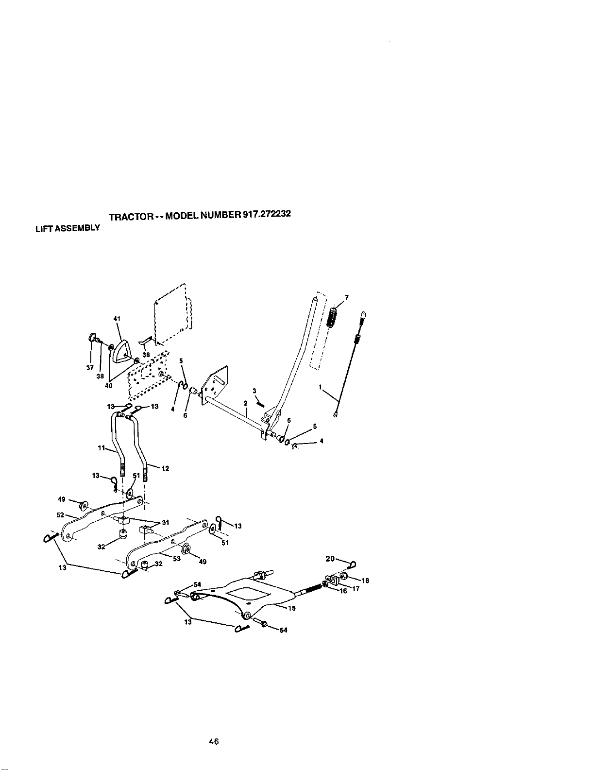
TRACTOR-- MODELNUMBER917.272232
LIFTASSEMBLY
46

TRACTOR -- MODEL NUMBER 917.272232
LIFTASSEMBLY
KEY PART
NO. NO. DESCRIPTION
1 176263 Plunger Assembly
2 159479 Shalt Assembly, Lift
3 178981 Pin, Groove
4 12000002 E.RJng
5 1_11621 Washer 21/32 x 1 x 91G_Jge
6 120183X Beadng, Nylon
7 175830 Gdp, Handle, Fluted
11 175370 Link, Lift, L.H.
12 175371 Link, Lilt, R.H.
13 49(0M Retainer Spring
15 175562 Link, Front
16 73350800 Nut, Hex, Jam 1/2-13 UNC
17 175689 Trunni_
18 738008(0 Nut Lockwiwsh 1/2-13 UNC
20 163552 Retainer Spdng
31 176205 Beadng, Fvt, Lift Spherical
3_ 175994 Nut, Lilt Unk 7/19-20
36 155097 P_4nterHeight Indicator
37 193935X Phx3Hole
38 17060516 Screw 5/19-_8 x 1
40 19112410 Washer 11/32 x 1-1/2 x 10 Ga
41 195099 Indicator Height Sht
49 145212 Nut Hex/Large LOCk
51 19171416 Washer
52 175802 Suspension AJ'mRH
53 175378 Suspension Arm LH
54 175560 Pin Flange
NOTE: Allcomponent dimensions given in U.S. Inches
1 inch = 25.4 mm
47
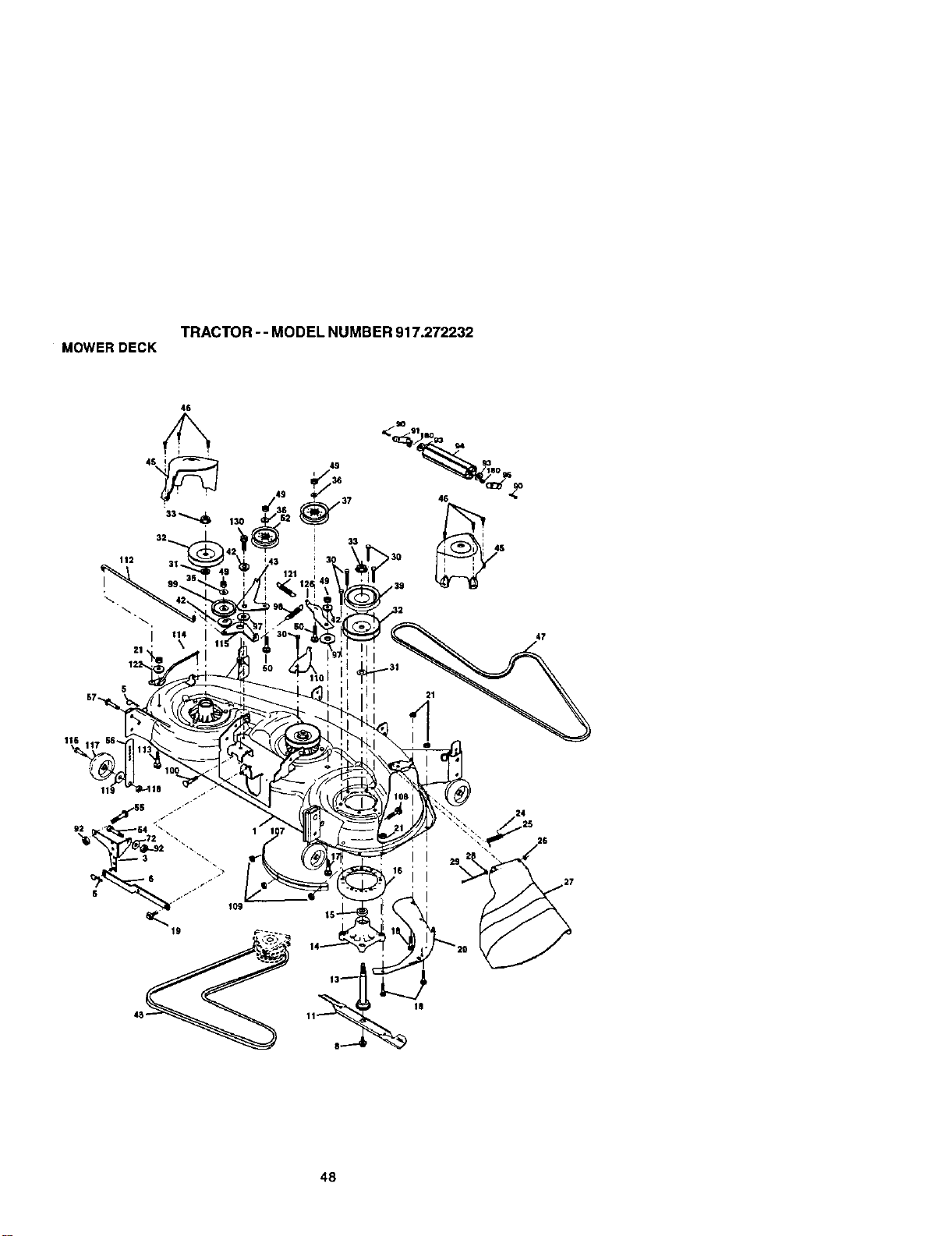
TRACTOR - - MODEL NUMBER 917.272232
MOWERDECK
46
49
i
I 33
47
48
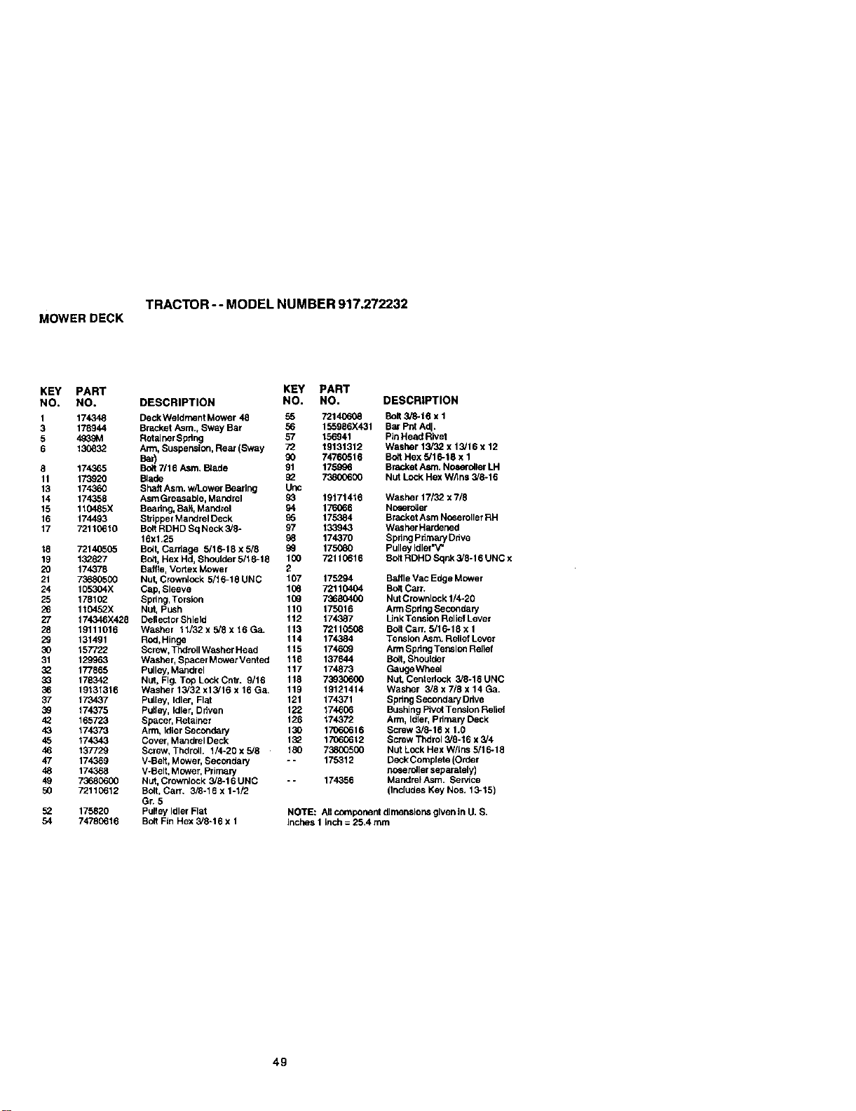
TRACTOR -- MODEL NUMBER 917.272232
MOWERDECK
KEY PART KEY PART
NO. NO. DESCRIPTION NO. NO. DESCRIPTION
1 174348 DeckWeldrnent Mower 48 55 72140608 Bolt 3/8-16 x 1
3 178944 Bracket Asm., Sway Bar 56 155986X431 Bar Pnt Adj.
5 4_9M Retainer Spflng 57 156941 PinHead Rivet
6 130832 Arm, Suspension, Rear (Sway 72 19131312 Washer 13/32 x 13/16 x 12
Bar) 90 74760516 BoltHex 5/16-t8 x 1
8 174365 Bolt 7/16 Asm. Blade 91 175996 Blacker Asm. Noserolter LH
11 173920 Blade 92 73800600 Nut Lock Hex W/Ins 3/8-16
13 174360 Shaft Asm. w/Lower Bearing Unc
14 174358 AsmGreasable, Mandrel 93 19171416 Washer 17/32 x 7/8
15 110485X Beadn9, Ball, Mandrel 94 176066 Noeero_er
16 174493 Stdpper Mandrel Deck 95 175384 Bracket Asm Noseroller RH
17 72110610 Bo8 RDHD Sq Neck 3/8- 97 133943 Washer Hardened
16xl.25 98 174370 SpringPdmaryDdve
18 72140505 Bolt,Carriage 5/16-18 x 5/8 9_ 175080 Pulley Idler'V"
19 132827 Bolt, Hex Hd, Shoulder 5/16-13 100 72110616 Bolt RDHD Sqnk 3/8-16 UNC x
20 174378 Baffle, Vortex Mower 2
21 73680500 Nut, Crownlock 5/16-16 UNC 107 175294 Baffle Vac Edge Mower
24 105304X Cap, Sleeve 106 72110404 Bolt Car_.
25 178102 Spring, Torsion 109 73680400 Nut Crownlock 1/4-20
26 110452X Nut, Push 110 175016 Arm SpringSecondary
27 174346X428 Deltector Shield 112 174387 Unk Tension Rolief Lever
28 19111016 Washer 11/32 x 5/8 x 16 Ga_ 113 72110508 Bolt Cart. 5/16-18 x 1
29 131491 Rod,Hinge 114 174384 Tension Asm. Relief Lever
30 157722 Screw, Thdroll Washer Head 115 174609 Arm SpdngTension Relief
31 129963 Washer, Spacer Mower Vented 116 137644 Bolt, Shoulder
3_ 177865 Pulley, Mandrel 117 174873 GaugeWheol
33 178342 Nut, Fig. Top Lock Cntr. 9/16 118 73930600 Nut, Centerlock 3/8-16 UNC
36 19131316 Washer 13/32 x13/16 x 16 Ga. 119 19121414 Washer 3/8 x 7/8 x 14 Ga.
37 173437 Pulley, Idler, Flat 121 174371 Spdng SecondaryDdve
39 174375 Putley, Idler, Driven 122 174606 BushingPIvotTension Relief
42 165723 Spacer, Retainer 128 174372 Arm, Idler, pfirnary Deck
43 174373 Arm, Idler Secondary 130 17060616 Screw 3/8-16 x 1.0
45 174343 Cover, Mandrel Deck 1:_ 17060612 Screw Thdrol 3/3-16 x 3/4
46 137729 Screw, Thdroll. t/4-20 x 5/8 180 73800500 Nut Lock Hex W/Lns 5/16-18
47 174369 V-Belt, Mower, Secondaly -- 175312 Deck Complete (Order
48 174368 V-Belt, Mower, Prima W noeerolter separately)
49 73630600 Nut,Crownlock 3/8-16UNC -- 174356 MandrelAsm. Service
50 72110612 Bolt, Can. 3/8-18 x 1-1/2 (Includes Key Nos. 13-15)
Gr. 5
52 175820 Pulley Idler Flat NOTE: All component dimensions given in U. S.
54 74780616 BottFin Hex 3/3-16 x 1 inches 1 inch = 25.4 mm
49
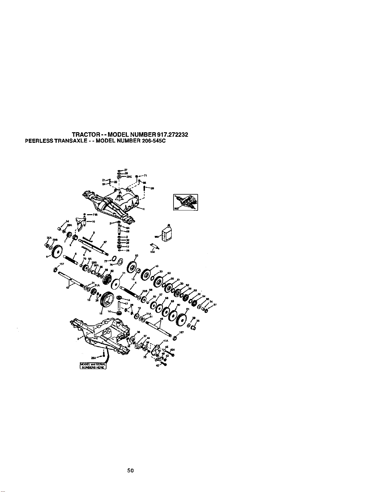
TRACTOR -- MODEL NUMBER 917.272232
PEERLESSTRANSAXLE- - MODELNUMBER206-545C
5O
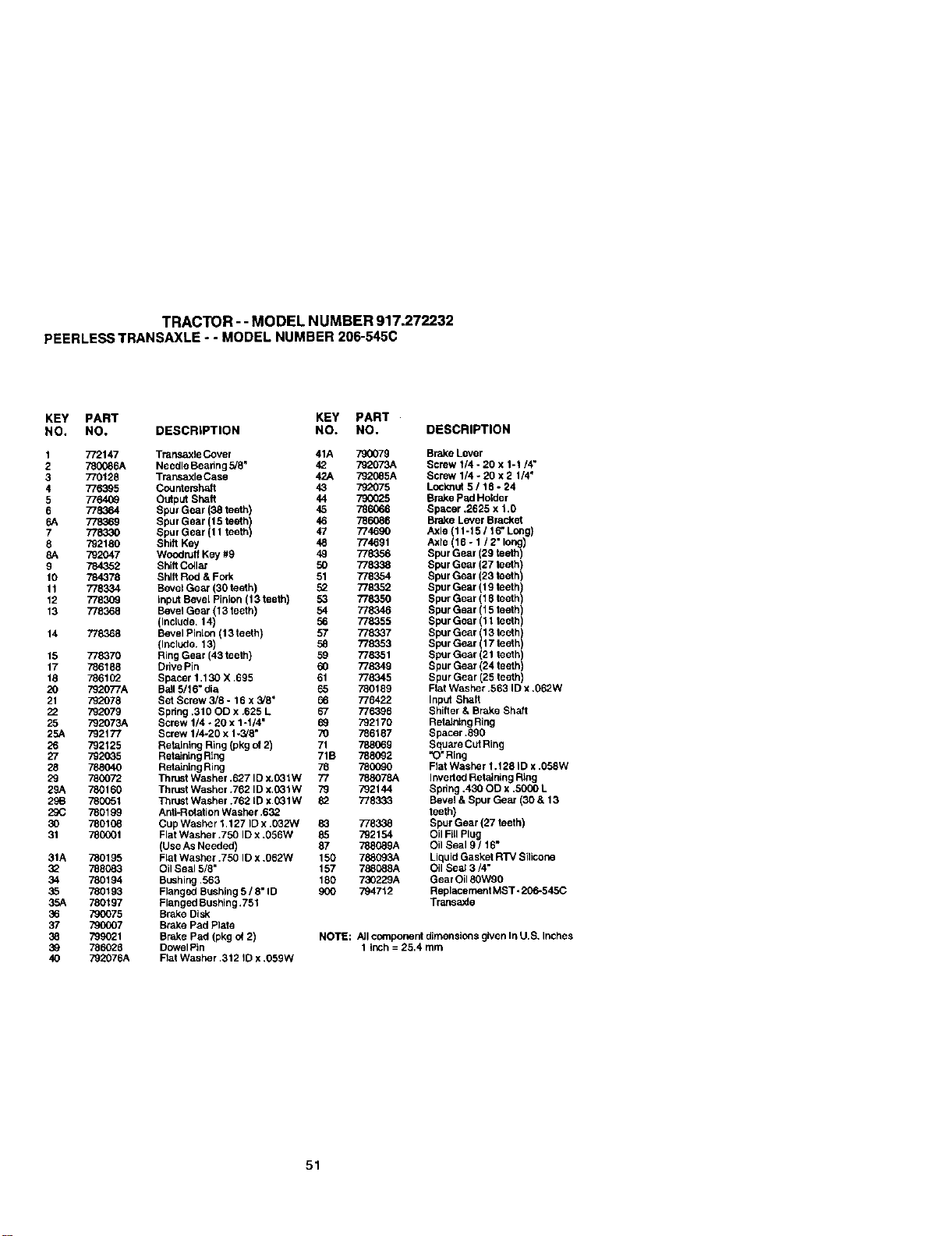
TRACTOR - - MODEL NUMBER 917.272232
PEERLESSTRANSAXLE- - MODELNUMBER206-545C
KEY PART KEY PART
NO. NO. DESCRIPTION NO. NO.
1 772147 Transaxle Cover
2 780086A Needle Beahng 5/8"
3 770128 Transaxle Case
4 776395 Countersh_t
5 776409 Outp_ Shaft
6 778364 Spur Gear (38 teeth)
6A 778369 Spur Gear 115teethI
7 778330 Spur Gear 11 teeth
8 792180 Shift Key
8A 792047 Woodruff Key #9
9 784352 Shilt Collar
10 784378 Shift Rod & Fork
11 778334 Bevel Gear (30 teeth)
12 778309 Input Bevel Pinion (13 teeth)
13 778368 Bevel Gear (13 teeth)
(Include. 14)
14 778368 Beval Pinten (13 teeth)
(Include. 13)
15 778370 Ring Gear (43 teeth)
17 786188 Drive Pin
18 786102 Spacer 1.130 X ,695
20 792077A Ball 5/16" die
21 792078 Set Screw 3/8 - 16 x 3/8"
22 792079 Spring .310 OD x .625 L
25 792073A Screw 1/4 - 20 x 1-1/4"
25A 792177 Screw 1/4-20 x 1-3/8"
26 792125 Retaining Ring (pkg of2)
27 792035 Retaining Ring
28 788040 Retaining Ring
29 780072 Thrust Washer .627 ID x.031W
29A 780160 Thruet Washer .762 ID x.031W
29B 780051 Thrust Washer .762 ID x.031W
29C 780199 AofI-Rofation Washer .632
30 780108 Cup Washer 1.127 ID x .032W
31 780001 Flat Washer .750 ID x .056W
(Use As Needed)
31A 780195 FlatWasher .750 ID x ,062W
3_ 788083 OilSeal 5/8"
34 780194 Bushing .563
35 780193 Flanged Bushing 5 / 8" ID
35A 780197 Flanged Bushing .751
36 790075 Brake Disk
37 790007 Brake Pad Plate
38 799021 Brake Pad (pkg of 2)
3_ 786028 DowelPin
40 792076A Flat Washer .312 ID x .059W
DESCRIPTION
41A 790079 Brake Lever
42 792073A Screw 1/4 - 20 x 1-1/4"
42A 792085A Screw 1/4 - 20 x 2 1/4"
43 792075 Le,cknof 5 / 18 - 24
44 790G25 Brake pad Holder
45 786066 Spacer .2625 x 1.0
46 786086 Brake Lever Bracket
47 774690 Axle (11-15 / 16" Long)
48 774691 Axle (16 - 1 / 2" long)
49 778356 Spur Gear (29 teeth)
50 778338 Spur Gear (27 teeth)
51 778354 Spur Gear (23 teeth)
52 778352 Spur Gear (19 teeth)
53 778350 Spur Gear (16 teeth)
54 778346 Spur Gear (15 teeth
56 778355 Spur Gear (11 tee h
57 778337 Spur Gear 113teeth I
58 778353 Spur Gea,r 17 teeth
59 778351 Spur Gear (21 teeth)
60 778349 Spur Gear (24 teeth)
61 778345 Spur Gear (25 teeth)
65 780189 Flat Washer .563 ID x .062W
66 776422 Inpu_ Shaft
67 776396 Shifter & Brake Shaft
69 792170 Retal_ng Ring
70 786187 Spacer .890
71 788069 Square CutRing
71B 7880_2 "O"Ring
76 780090 Flat Washer 1.128 ID x .058w
77 788078A Inverted Retaining Rtng
79 792144 Sphng,4300Dx,5000L
82 778333 Bevel & Spur Gear (30 & 13
teeth)
83 778338 Spur Gear (27 teeth)
85 792154 Oil Fill Plug
87 788(_9A Oil Seal 9 / 16-
150 788093A Liquid Gacket RTV Silicone
157 788088A Oil Seal 3/4"
180 730229A Gear Oil 80W90
900 794712 Replacement MST -20_545C
TransaxLe
NOTE: A]Icon_pormnt dimensions given In U.B, Inches
1 inch = 25,4 rnm
51
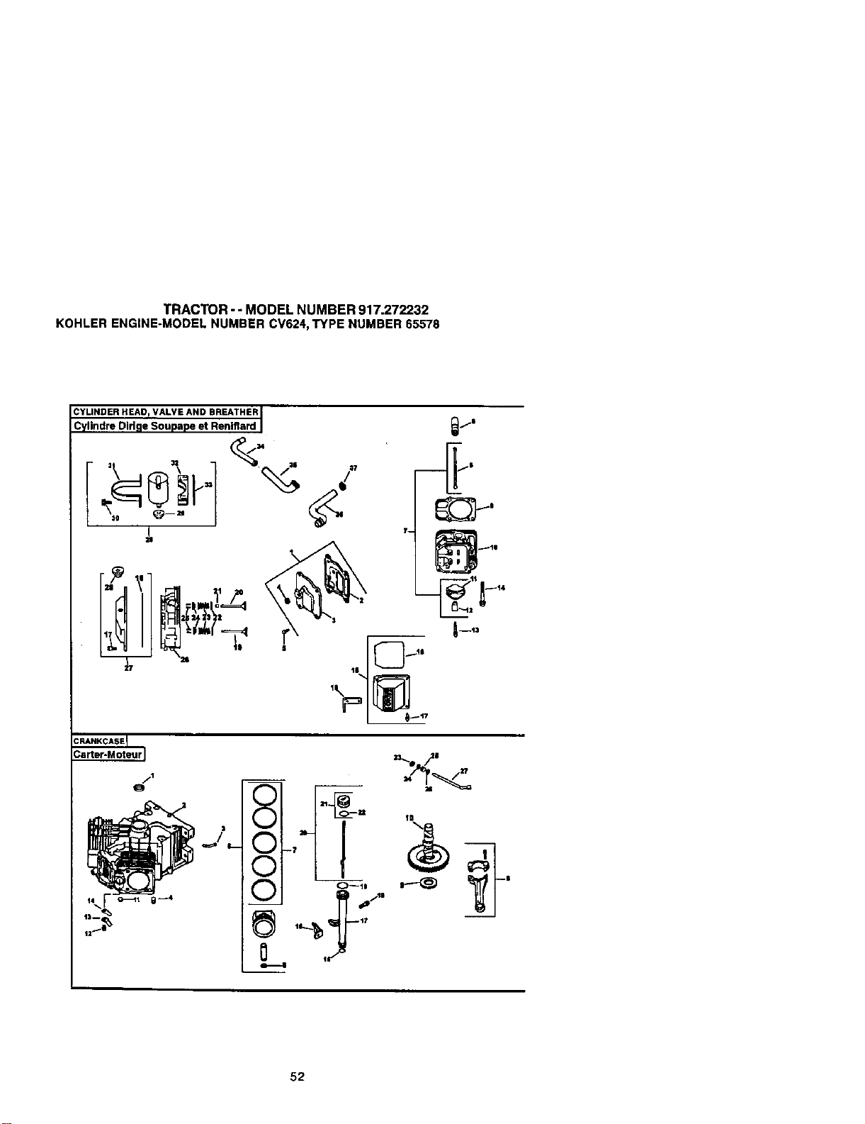
TRACTOR - - MODEL NUMBER 917.272232
KOHLERENGINE-MODELNUMBERCV624,TYPE NUMBER65576
_lLinNdrE:Did_oe'SO/uL_pAeNetRREnlAfl: _dRI
|
11
52
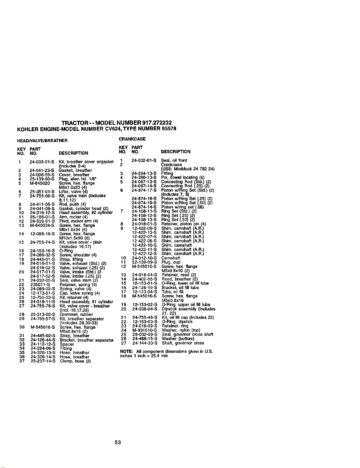
TRACTOR - - MODEL NUMBER 917.272232
KOHLERENGINE-MODELNUMBERCV624,TYPE NUMBER65578
HEAD/VALVE/BREATHER
CRANKCASE
KEY PART KEY PART
NO. NO. DESCRIPTION NO. NO, DESCRIPTION
1 24-033-01-S Kit, breather cover w/gask_ 1 24-032-01-S Seal, oil front
(Includes 2-4) 2 Crankcase
2 24-041-23-S Gasket. breather (USE: Miniblock 24 782 24)
3 24-096-59-S Cover. breather 3 24-294-13-S Fittin
4 25-139-60-S Plug. alien hd. 1/8" 4 24-380-13-S Pin. o_owel locating(6)
5 M-645020 Screw. hex. flange 5 24-067-13-S Connecting Rod (Std.) (2)
M6xtOx20 (4) 24-067-14-S Connecting Rod (.25) (2)
Piston w/Rlag Set (Std.) (2)
6 25-351-01-S Lifter, valve (4) 6 24-874-17-S (Includes 7, 8)
7 24-755-66_S Kit, valve train (Includes
8,11,12) 24-874-18-S Piston w/Ring Set .25) (2
8 24-411-05-S Rod, push (4) 24-874-19-S Piston w/Ring Set (.50) (2)
9 24-041-08-S Gasket, cylinder head 12) 24-874-14-S Piston w/ring set (.08)
10 24-318-12-S Head assembly, #2 cylinder 7 24-108-11-S Ring Set (Std.) (2)
11 25-186-01-S Arm, rocker 4) 24-108-12-S Ring Set .25/ 2
12 24-599-01-S Pvet, rockerarrn 4 24-108-13-S Ring Set .50 2
13 M-640034-S Screw, hex. flange 6 24-018-0t-S Retainer, piston pin (4)
M6x1.Ox34 (4) 9 12-422-09-S Shim, camshaft _A.R._
14 12-O86-16-S Screw, hex. flange 12-422-13-S Shim, camshaft A.R.
M1Oxl.Sx90 (8) 12-422-07-S Shim, camshaft I_IA,R.
15 24-755-74-S Kit, valve cover - plain 12-422-08-S Shim, camshaft .R.
12-422-10-S Shim, camshaft
(Includes 16,17)
16 24-153-16-S O-Ring 12-422-11-S Shim, camshaft IA.R.I
17 24-086-32-S Screw, shoulder (4) 12-422-12-S Shim, camshaft A.R.
18 24-445-01-S Strap, li_ng 10 24-012-10-S Camshaft
t9 24-016-01-S Valve, exhaust (Std.) (2) 11 52-139-09-S Plug, cup
24-016-02-S Valve, exhaust (.25) (2) 12 M-545010-S Screw, hax. flange
20 24-017-01-S Valve, intake (Std.) (2 M5x0.Sxl0 (2)
24-O17-02-S Valve, intake (,25) (2) 13 24-018-04-S Retainer, reed (2)
21 24-O32-05-S Seal, valve stem (2) 14 24-402-O5-S Reed, breather (2)
15 12-153-01-S O-Ring, lower o_1tilt tube
16 24-126-19-S Bracket, oil fill tube
22 235011-S Retainer, spring (4)
23 24-089-02-S Spring, valve (4)
24 12-173-01-S Cap, valve spring (4) 17 12-123-04-S Tube, oil fib
25 12-755-03-S Kit, retainer (4) 18 M-545016-S Screw, hex. flange
26 24-316-11-S Head assembly, #1 cylinder M5x0.8x16
27 24-755-76-S Kit, valve cover - breather 19 12-153-02-S O-Ring, upper oil fill tube
(Incl. 16,17,28) 20 24-038-O4-S Dipstick assembly (Includes
28 25-313-02-S Grommet, rubber 21, 22)
29 24-755-57-S Kit, breather separator 21 24-755-46-S Kit, oil fill cap (Includes 22)
(Includes 26,30-33) 22 12-153-O3-S O-Ring, dipstick
30 M-545016-S Screw, hex. flange 23 24-018-09-S Retainer, ring
24 M-931010-S Washer, nylon (top)
MSxO,6x16 (2)
31 24-445-02-S Strap, breather 25 28-032-09-S Seal, governor cross shaft
32 24-126-44-S Bracket, breather separator 26 24-468-15-S Washer {bottom)
27 24-144-33-S Shaft, governor cross
33 24-112-12-S Spacer
34 24-294-06-S Fitting
35 24-326-13-S Hose, breather NOTE: All component dimensions given in U.S.
36 24-326-14-S Hose, breather inches 1 inch = 25.4 mm
37 25-237-14-S Clamp, hose (2)
53
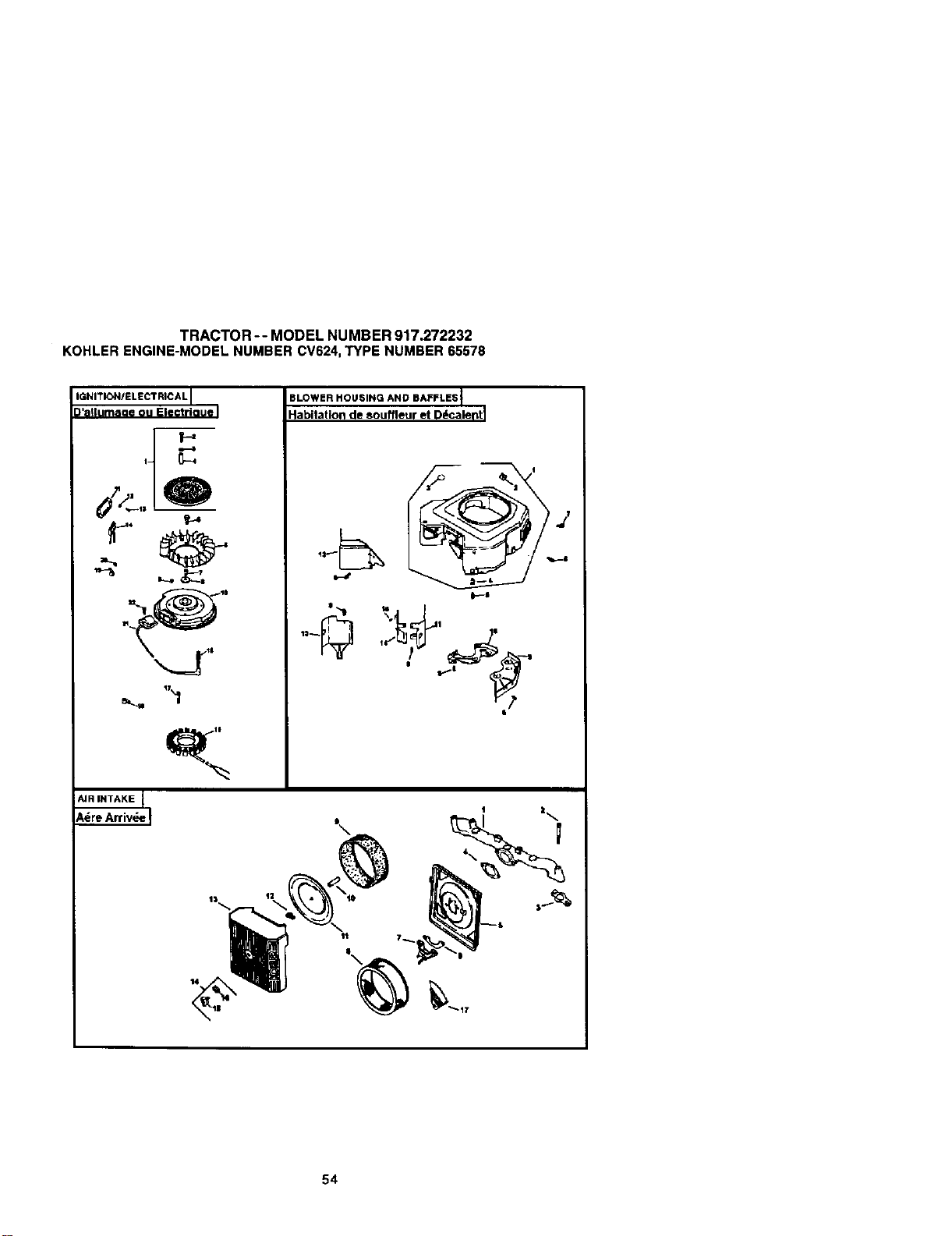
TRACTOR -- MODEL NUMBER 917.272232
KOHLERENGINE-MODELNUMBERCV624,TYPENUMBER65578
IGNITIONIELEOTRICA LI
)'allumaae ou Electrioue I
i, _--4
t-+
tq_ 11
AIR INTAKE J
SLOWERHOUSINGANDBAFFLESt
Habitation de souffleur et D_caleFt I
54
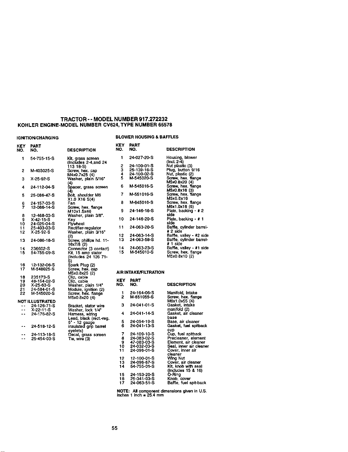
TRACTOR - - MODEL NUMBER 917.272232
KOHLERENGINE-MODELNUMBERCV624,TYPE NUMBER65578
IGNITION/CHARGING BLOWER HOUSING & BAFFLES
KEY PART KEY PAWr
NO, NO. DESCRIPTION NO. NO. DESCRIPTION
1 54-755-15-S Kit. grass screen 1 24-027-20-S
(Includes 2-4,and 24
113 18-S) 2 24-100-01-S
2 M-403025-S Screw, hex. cap 3 25-139-16-S
M4xO,7x25 _4 4 24-100-02-S
3 X-25-92-S Washer, pain 5/16" 5 M-545020-S
4 24-112-04-S IA_) screen
pacer, grass 6 M-545016-S
/.4
5 25-086-47-S _ M6
olt, shou der 7 M-551016-S
XI.O X16 S(4)
6 24-157-03-6 Fan 8 M-645016-S
7 12-086-14-S Screw, hex. flange
M10x1.5x46 9 24-146-16-S
8 12-466-03-S Washer, plain 3/8".
9 X'42"15"6 Key 10 24-146-20-S
10 24-02fl-04-S Fty_neel
11 25-403-03-S Rec_fier-regulator 11 24-063-20-S
12 X-25-92-S Washer, plain 3/16"
(2) 12 24-063-14-S
13 24-086-18-S Screw, phillips hd. 11- 13 24-063-58-S
16x7/8 (2)
14 236602-S Connector (3 contact) 14 24-063-23-S
15 54-755-09-S Kit, 15 amp stator 15 M-545610-S
(Includes 24 126 71-
s)
16 12-132-06-S Spark Plug (2)
17 M-548025-S Screw, hex. cap
M5xg.8x25 (2) AIR INTAKE/FILTRATION
18 235173-S Clip, calve
19 48-164-02-S Clip, cable KEY PART
20 X-25-03-S Washer, plain 1/4" NO, NO. DESCRIPTION
21 24-584-01-S Module, ignition (2)
22 M-545020-S Screw. hex. flange 1 24-164-06-S
M5xO.ex20 (4) 2 M-651055-S
NOT ILLUSTRATED
- - 24-126-71-S Bracket, stetor wire 3 24-041-01-S
-- X-22-11-S Washer, lock 1/4 °
-- 24-176-82-S Harness, wiring 4 24-041-14-S
Lead, black (rect.-reg.
5" - 12 gauge 5 24-094-19-S
-- 24-518-12-6 insulated grip barrel 6 24-041-13-S
eyelets)
-- 24-113-18-S Decal, grass screen 7 24-109-10-S
- - 25-454-03-S 33e. wire (3) 8 24-063-02-S
9 47-083-03-S
1O 24-032-03-S
11 24-096-01-6
12 12-100-01-S
13 24.O96-67-S
14 54-755-01-S
15 24-153-20-S
16 25-341-03-S
17 24-063-51-S
Housing, blower
(Incl.2-4)
Nut plasflc (3)
Plug, button 9/16
Nut, plastic (2)
Screw, hex. flange
MSxO.8x20(4)
Screw, hex. flange
M5x0.gx16 (3)
Screw, hex. flange
M5x0.6x16
Screw, hex. flange
M6xl.0x16 6)
Pate, backng - # 2
side
Plate,backing - # 1
sicie
Baffle, cylinderbarrel-
# 2 side
Baffle,valley - #2 side
Baffle, cylinder barrel-
# 1 side
Baffle, valley - #1 side
Screw, hex. flange
M5xO6x10 (2)
Manifold, intake
Screw, hex. flange
M6x1.0x55 (4)
Gasket, intake
manifold (2)
Gasket, mr cleaner
base
Base, air cleaner
Gasket, fuel spifback
cup
Cup, fuel spifback
Precleaner, element
Element, air cleaner
Seal, inner air cleaner
Cover, inner aLr
cleaner
Wing Net
Cover, air cleaner
Wit, knob with seal
(Includes 15 & 16)
O-Ring
Knob, cover
Baffle, fuel spif-back
NO'RE: All componentdimensionsgivenin U.S
inches1 inch = 25.4 mm
55
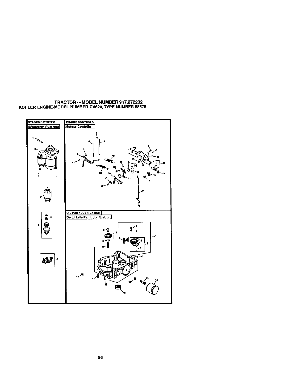
TRACTOR -- MODEL NUMBER 917.272232
KOHLERENGINE-MODELNUMBERCV624,TYPENUMBER65578
_TARTING 5YS'I'EMI
3dmsrrant Svlt_mel
I
$
ENGINECONTROLS
Moteur Contr61e
\ _ _,._.
._ . p _-_,.
OIL PAN! LUBRICATION I
De L'Hulle Fan Lubrlflcatlon I
q
I
O! " _I
56
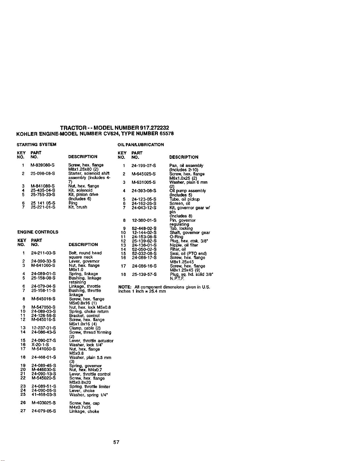
TRACTOR - - MODEL NUMBER 917.272232
KOHLERENGINE-MODELNUMBERCV624,TYPE NUMBER65578
STARTING SYSTEM
KEY PART
NO. NO.
1 M-839080-S
2 25-098-08-S
3 M-84t080-S
4 25-435-04-S
5 25-755-33"5
6 25 141 05-S
7 25-221-01-S
ENGINE CONTROLS
KEY PART
NO. NO.
1 24-211-03-S
2 24-090"33-S
3 M-641060"S
4 24-089-01 -S
5 25-158-08-S
6 24-079-04-S
7 25-158-11-S
8 M-545016-S
9 M-547050-S
10 24-089-O3-S
11 24-126-56-S
12 M-645016-S
13 12-237-01-S
14 24°086-43-5
15 24-090-07-S
16 X-20-1-S
17 M-541050-S
18 24-468_O1-S
19 24-089"45-S
20 M-446030-S
21 24-090-13-S
22 M-545020-S
23 24-089-51-S
24 24-090-05-S
25 41-468-03-S
26 M-403025-S
27 24-079-05-S
OIL PAN/LUBRICATION
KEY PART
DESCRIPTION NO. NO. DESCRIPTION
Screw, hex, flange 1 24-199-07-S
M8x1,25xS0 2_
Starter, so enoldshft 2 M-645025-S
assembly (includes 4-
I_'ut, 3 M-631005-S
hex,
flange
Kit, solenoid 4 24-393-08-S
Kit, pinionddve
(Includes6) 5 24-123-05-S
F_tngbrush 6 24-162-26-S
7 24-043-12-S
DESCRIPTION
Bolt, round head
square neck
Lever, governor
Nut, hex. flange
M6xl.0
Sprin.g, linkage.
Bushing, linkage
retaining
Linkage, throttle
Bushing, throttle
linkage
Screw, hex. flange
M5xO.8x16 1)
Nut, hex. ock M5x0.8
Spring, choke return
Bracket, control
Screw, hex. flange
M6x1.0x16 4)
Clamp, cabe 2
Screw, thread formk_g
(2)
Lever, _rotlle actuator
Washer, lock 1/4"
Nut, hex. flange
M5x0.8
Washer, plain 5.5 mm
(3)
Spring, governor
NUT, hex. M4xO.7
Lever, throttle convol
Screw, hex. flange
M5xO.8x20
Spdng, throt_e ,miter
Lever, choke
Washer, spring 1/4"
Screw, he.x. cap
M4x0.7x25
Linkage, choke
12-380-01-S
9 52-448-02-S
10 12-144-02-S
11 24-153-08-S
12 25-139-62-S
13 24-136-01-S
14 52-050-02-S
15 52-032-08-S
16 24-086-17-S
17 24-086-16-S
18 25-139-57-S
Pan, oil assembly
_ncludes 2-10)
crew, hex. flange
M6x1.0x25 (2)
Washer, plaLn6 mm
(_!1 pump assembly
(Includes 5)
Tube, oil pickup
Screen, oil
Kit, governor gear w/
Indudes 8)
Pin, governor
re ulatin
,ock,%g
Shaft, governor gear
O-Rin
g
Plug, 6ex. ctsk. 3/8"
Nipple, oil filter
Filter, oil
Boai, oil (PTO end)
Screw, hex. flange
MSx1.25x45
Screw, hex. flange
M8xl.25x45 (9)
Plug, sq. hd. solid 3/8'
N.F_T.F.
NOTE: All component dimensions g_ven in U.S.
inches 1 inch = 25.4 mm
57
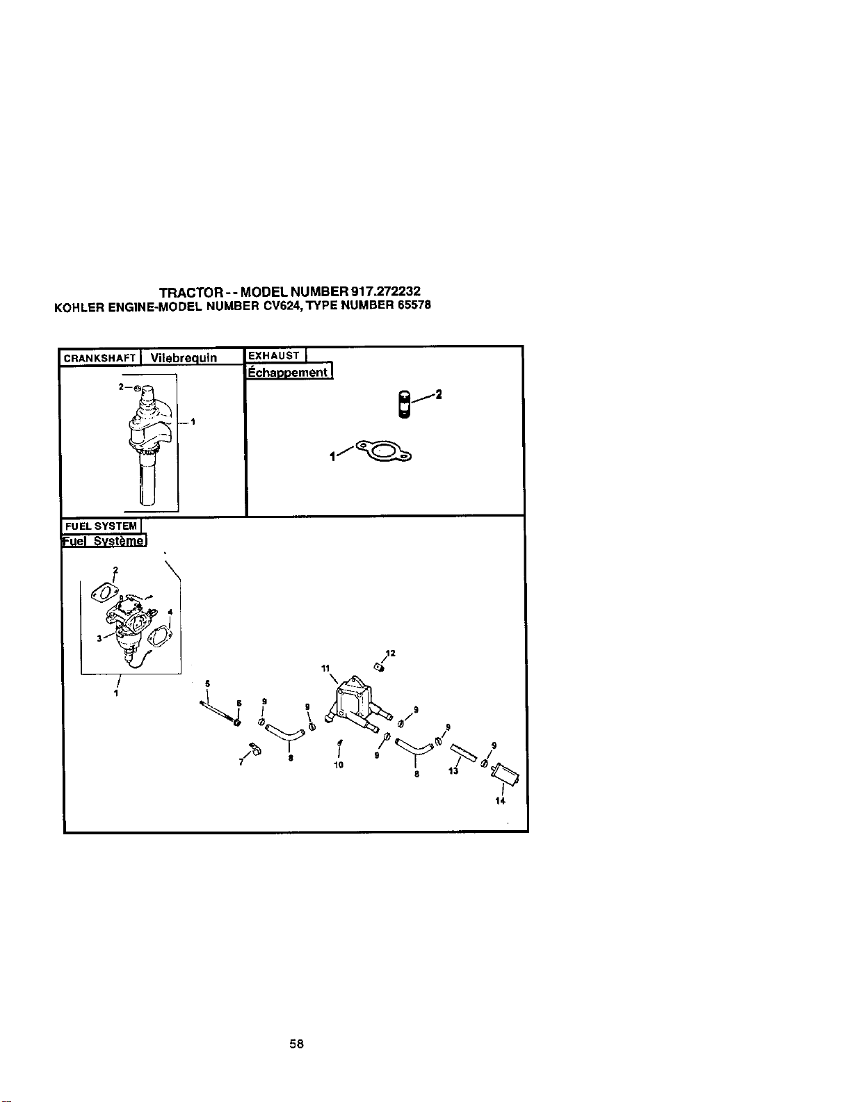
TRACTOR -- MODEL NUMBER 917.272232
KOHLERENGINE-MODELNUMBERCV624,TYPE NUMBER65578
:RANKSHAFT Vilebrequin
2-_ --i
EXHAUST
EchaDDement I
_j2
:UEL SYSTEM I
Fuel Svsti)me I
/
1
14
58
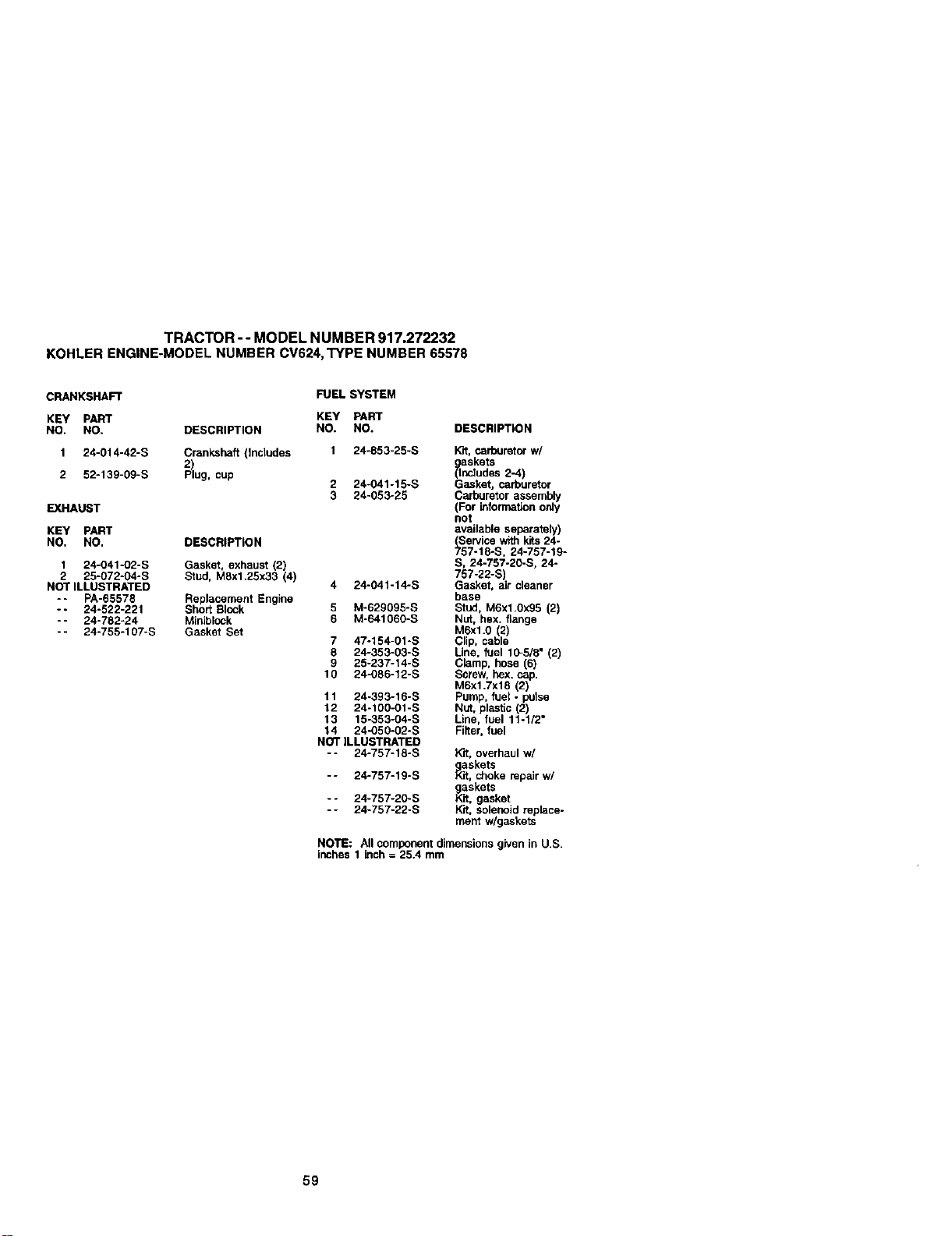
TRACTOR - - MODEL NUMBER 917.272232
KOHLER ENGINE-MODELNUMBERCV624,TYPE NUMBER65578
CRANKSHAFT
KEY PART
NO. NO. DESCRIPTION
1 24-014-42-S Crankshaft (Inbludes
2
2 52-139-g9-s Pug, cup
EXHAUST
KEY PART
NO. NO. DESCRIPTION
1 24-041-02-S Gasket, exhaust (2)
2 25-072-04-S Stud, MSx1,25x33 (4)
NOT ILLUSTRATED
-- PA-65578 Replacement Engine
-- 24-522-221 Short Block
- - 24-782-24 Miblblock
- - 24-755-107-S Gasket Set
FUEL SYSTEM
KEY PART
NO. NO. DESCRIPTION
1 24-853-25-S Wrt,carburetorw/
askets
_nbludes 2-4)
2 24-041-15-S G_sket, carburetor
3 24-053-25 Carburetor assembly
(For informationonly
not
available separateiy)
Servicewithkits24-
_57-18-S, 24-757-19-
S, 24-757-20-S. 24-
757-22-S)
4 24-041-14-S Gasket, air cleaner
base
5 M-629gg5-s Stud, M6x1.0x95 (2)
6 M-641060-S Nut, bux. flange
M6xl.0 2)
7 47o154-01-S C p, cabe
8 24-353-03-S Line, fuel 10-5/8° (2)
9 25-237-14-S Clamp, hose (6)
10 24-O86-12-S Screw, hex.cap.
M6x1.7x18 (2)
11 24-393-16-S Pump, fuel- pulse
12 24-100-01-S Nut, plastic(2)
13 15-353-04-S Line, fuel 11o1/2"
14 24-050-02-S Filter,fuel
NOT ILLUSTRATED
-- 24-757-18-S K'_,overhaulw/
askets
,_it, c_oke repairw/
askets
_k, gasket
Kit, solenoidreplace-
ment w/gaskets
-- 24-757-19-S
-- 24-757-2_S
-- 24-757-22-S
NOTE: Allcomponentdimensionsgiven in U.S.
inches 1 inch= 25.4 mm
59

60

61

62
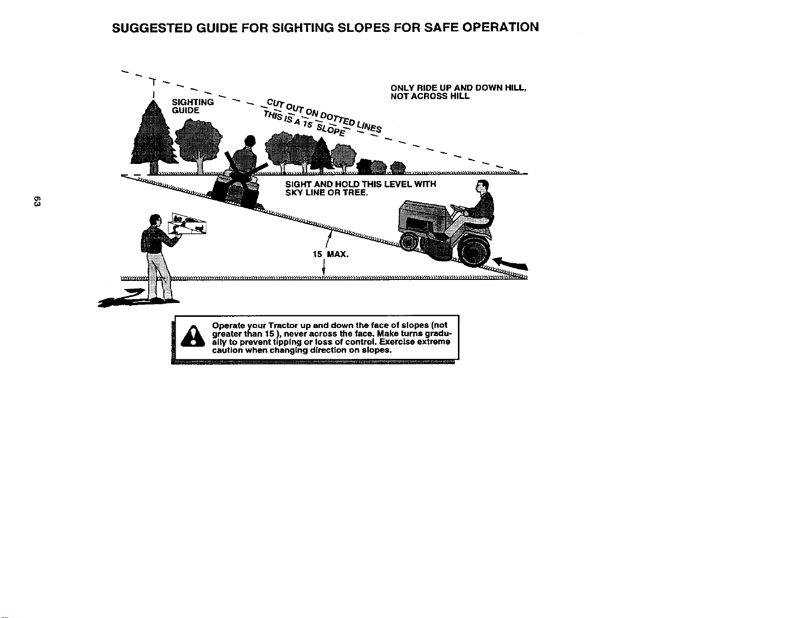
SUGGESTED GUIDE FOR SIGHTING SLOPES FOR SAFE OPERATION
ONLY RIDE UP AND DOWN HILL,
NOT ACROSS HILL
o_
¢o
[__ _cautio/NOperate your Tractor up and down the face of slopes (not
I
AJk greater than 15 !, never across the face. Make turns gredu- I
ally to prevent tipping or loss of control. Exercise extreme
n when changing direction on slopes. I

Forrepairofmajorbrandappliancesinyourown home...
nomatterwhomadeit,nomatterwhosoldit]
1-800-4-MY-HOME e Any_e,dayo_niglt
(14300-469-4e&3) (U.SAandC_da)
WWWJ_'8.¢Om WWW,SI_tS.Ca
ForrepaFrofcarry4nproductslikevacuums,lawnequipment,and
electronics,callforthenearestSearsPartsand RepairCenter.
1-800-488-1222 Anyene,dayornight(U.S.A.ore)
www.lleal_corn
Forthereplacementparts,accessoriesandowner'smanuals
thatyouneedtodo-it-yourseff,callSearsPertsDirectS_!
1-800-366-PART
(1-800-36_7278)
6 am.- 11pm., 7daysa week
(u.s.__y)
wv_.seerLc_oad=lirect
To purchaseor inquireabouta SearsServiceAgreement
orSearsMaintenanceAgreement
1-800-827-6655 (u.s._.) 1-800-361-6665 (Carada)
7&m. -5 pJn.,CST, Mort.- Sat. 9&m. - 8p.m.EST,M- F,4 I_m. Sal.
parape6rr_ de re_ a AuCanadapeurserv_ enfr_
domlctio,ypare ordererpiezas; 1-8004.E-FOYER"c
1-888"SU'HOGARsM (1-8C0-533-68G7)
(1-888-784-6427) w_w_,rs.ca
H°meCentral®J
® Registered Trademark /1e Trademark / su Service Mark o! Seam, Roebuck and Co.
® Mama Regls_'ada / _ Mama de Fdbrk:a/ su Mama de Sorviclo de Seam, Roebuck and Co.
_c Marque de commerce / _o Marque d_posde de Sears, Roebuck and Co.
179180 3.26.01 TR Printedin U.S,A.


