
Loading ...
Loading ...
Loading ...
ENGLISH
5
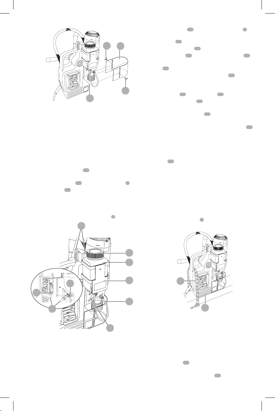
Fig. C
16
19
19
20
Lubrication System (Fig. A, D)
Filling the Coolant Bottle
WARNING: Do not pour cutting fluid into the
bottle while mounted in the bracket. Do not
allow cutting fluid to enter the drill motor. Electric
shock mayresult.
NOTE: The lubrication system is designed for dispensing
cutting fluids specifically intended for drilling. Other liquids
may damage thesystem.
1. Turn the the flow regulator
13
counterclockwise to
close.
2. Remove coolant bottle
10
from magnetic bracket
5
.
3. Unscrew the cap
21
.
4. Fill the container with cutting coolant diluted
withwater.
5. Screw the cap back on.
6. Place coolant bottle into magnetic bracket
5
.
Fig. D
22
11
5
10
21
13
12
23
11
Fitting the Lubrication System
(Fig. A, D)
WARNING: Do not use the lubrication system in
vertical surfaces or overhead drilling applications.
Only use the lubrication system for horizontal drilling
applications, as shown in FigureA.
1. Place coolant bottle
10
into the magnetic bracket
5
,
then slide the magnetic bracket onto the either side of
the steel strip
22
.
2. Attach the coolant tube
11
to the coolant bottle:
a. Remove the nut
23
and thread it onto the tube
11
.
b. Slide the tube onto the nipple and tighten the
nut
23
.
3. Attach the tube to the coupling connector
12
on
thegearbox.
a. Remove the nut from the connector, then pass the
coolant tube
11
through the nut
23
.
b. Slide the coolant tube
11
onto the nipple to install,
then tighten the nut.
c. To remove, loosen the nut
23
, then pull the tube
from the connector.
In order to use the lubrication system, the coolant bottle
10
must be filled with a sufficient amount of cuttingfluid.
Lubrication in horizontal applications
(Fig. D)
1. Adjust the fluid flow as required using the flow
regulator
13
.
2. Add more cutting fluid if the shavings become blue.
Lubrication in Vertical and overhead
applications
Dip the cutter in cutting paste or apply an appropriatespray.
Fitting the Safety Chain (Fig. E)
WARNING: Always use the safetychain.
Feed the provided safety chain
9
through the handle of
unit and around the workpiece and secure in place.
Fig. E
9
15
Inserting and Removing an Accessory
(Fig. F, G)
The tool holder accepts annular cutters with a 3/4" shank
with two flats.
CAUTION: Laceration hazard. The cutter teeth
aresharp.
1. Slide the pilot pin
26
through the hole in the center of
the cuttershank.
2. Push up on the quick-release collar
24
.
Loading ...
Loading ...
Loading ...