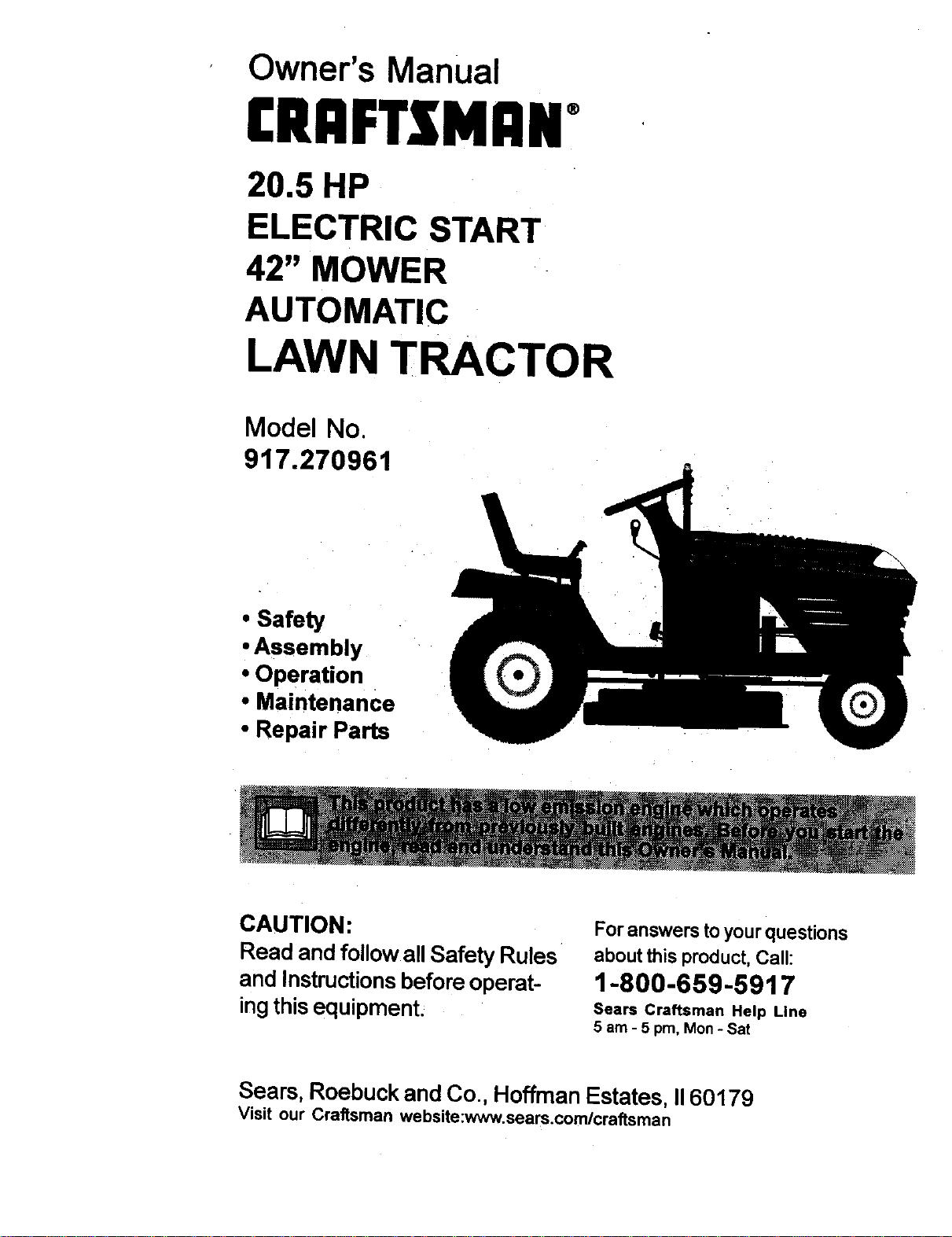
Owner's Manual
£RAFTZMANo
20.5 HP
ELECTRIC START
42" MOWER
AUTOMATIC
LAWN TRACTOR
Model No.
917.270961
• Safety
• Assembly
• Operation
• Maintenance
• Repair Parts
CAUTION:
Read and followall Safety Rules
and Instructionsbefore operat-
ingthisequipment.
For answers to yourquestions
about this product, Call:
1-800-659-5917
Sears Craftsman Help Line
5 am - 5 pro, Mon - Sat
Sears, Roebuck and Co., Hoffman Estates, II60179
Visit our Craftsman website:www.sears.comlcraftsman
Warranty................ :............. _.................. 2
Safety Rules ......... i ...... ...... _.................. 2
Product Specifications ......._...._ ............. 5
Assembly ....... :......_ ...... _ 'o ...... 7
Operatio n ....... .i...... ....... _......_............... 11
Maintenance Schedule _......:................ 18
Maintenance ....................................... 18
Service and Adjustments .................... 22
Storage ............................................... 29
Troubleshooting ................................. 30
Repair Parts........................................ 34
Parts Ordering .................... .Back Cover
v t
LIMITED TWO YEAR WARRANTY ON CRAFTSMAN RIDING EQUIPMENT
For two (2) years from the date of purchase, if this Craftsman Riding Equipment is
maintained, lubricated and tuned up according to the instructions in the owner's
manual, Sears will re]_.ir or replace, free of charge, any parts found to be defective in
material or workmanship.
This Warranty does not cover:
• Expendable items which become worn during normal use, such as blades, spark
plugs, air cleaners, belts, etc.
• Tire replacement or repair caused by punctures from outside objects, such as nails,
thorns, stumps, or glass.
• Repairs necessary because of operator abuse, negligence, improper storage or
accident or the failure to maintain the equipment according to the instructions
contained in the owner's manual.
• Riding equipment used for commercial or rental purposes.
LIMITED 90 DAY WARRANTY ON BATTERY
For ninety (90) days from date of purchase, if any battery included with this riding
equipment proves defective in material or workmanship and our testing determines the
battery will not hold a charge, Sears will replace the battery at no charge. In-home
warranty service on your Craftsman riding equipment is available at no charge for 30
days from the date of purchase. Please contact your nearest service center. After 30
days from the date of purchase, warranty service is available by taking your Craftsman
riding equipment to your nearest Sears Service Center. (In-home warranty service will
still be available after 30 days from the date of purchase but a standard trip charge will
apply). This warranty applies only while this product is in the United States. This
Warranty gives you specific legal rights, and you may also have other rights which may
vary from state to state.
SEARS, ROEBUCKAND CO., D/817 WA, HOFFMAN ESTATES, IL 60179
IMPORTANT: This cutting machine is
capable of amputating hands and feet
and throwing objects: Failure to observe
the following safety instructions could
result in serious injury or death.
GENERAL OPERATION
• Read, understand, and follow all
instructions in the manual and on the
machine before starting.
• Only allow responsible adults, who are
familiar with the instructions, to
operate the machine.
• Clear the area of objects such as
rocks, toys, wire, etc., which could be
picked up and thrown by the blade.
• Be sure the area is clear of other
people before mowing. Stop machine
if anyone enters the area.
• Never carry passengers.
• Do not mow in reverse unless abso-
lutely necessary. Always look down
and behind before and while backing.
• Be aware of the mower discharge
direction and do not point it at anyone.
Do not operate the mower without
either the entire grass catcher or the
2 guard in place.
• Slowdownbeforeturning.
• Never leave a running machine
unattended. Always tum off blades, set
parking brake, stop engine, and
remove keys before dismounting.
• Tum off blades when not mowing.
• Stop engine before removing grass
catcher or unclogging chute.
• Mow only in daylight or good artificial
light.
• Do not operate the machine while
under the influence of alcohol or
drugs.
• Watch for traffic when operating near
or crossing roadways.
• Use extra care when loading or
unloading the machine into a trailer or
truck.
• Data indicates that operators, age 60
years and above, are involved in a
large percentage of riding mower-
related injuries. These operators
should evaluate their ability to operate
the riding mower safely enough to
protect themselves and others from
serious injury.
SLOPE OPERATION
Slopes are a major factor related to loss-
of-control and tipover accidents, which
can result in severe injury or death. All
slopes require extra caution. If you
cannot back up the slope or if you feel
uneasy on it, do not mow it.
DO:
• Mow up and down slopes, not across.
• Remove obstacles such as rocks, tree
limbs, etc.
• Watch for holes, ruts, or bumps.
Uneven terrain could overturn the
machine. Tall grass can hide ob-
stacles.
• Use slow speed. Choose a low gear
so that you will not have to stop or shift
while on the slope.
• Follow the manufacturer's recommen -
dations for wheel weights or counter-
weights to improve stability.
• Use extra care with grass catchers or
other attachments. These can change
the stability of the machine.
• Keep all movement on the slopes slow
and gradual. Do not make sudden
changes in speed or direction.
• Avoid starting or stopping on a slope..If
tires lose traction, disengage the
3
blades and proceed slowly straight
down the slope.
DO NOT:
• Do not turn on slopes unless neces-
sary, and then, tum slowly and
gradually downhill, if possible.
• Do not mow near drop-offs, ditches, or
embankments. The mower could
suddenly turn over if a wheel is over
the edge of a cliff or ditch, or if an edge
caves in.
• Do not mow on wet grass. Reduced
traction could cause sliding.
• Do not try to stabilize the machine by
putting your foot on the ground.
• Do not use grass catcher on steep
slopes.
CHILDREN
Tragic accidents can occur if the operator
is not alert to the presence of children.
Children are often attracted to the
machine and the mowing activity. Never
assume that children will remain where
you last saw them.
• Keep children out of the mowing area
and under the watchful cars of another
responsible adult.
• Be alert and turn machine off if
children enter the area.
• Before and when backing, look behind
and down for small children.
• Never carry children. They may fall off
and be seriously injured or intedere
with safe machine operation.
• Never allow children to operate the
machine.
• Use extra care when approaching
blind corners, shrubs, trees, or other
objects that may obscure vision.
SERVICE
• Use extra care in handling gasoline
and other fuels. They are flammable
and vapors are explosive.
Use only an approved container.
Never remove gas cap or add fuel
with the engine running. Allow
engine to cool before refueling. Do
not smoke.
Never refuel the machine indoors.
Never store the machine or fuel
container inside where there is an
open flame, such as a water
heater.
• Never run a machine inside a closed
area.
• Keep nuts and bolts, especially blade
attachment bolts, tight and keep
equipment in good condition.
• Never tamper with safety devices.
Check their proper operation regu-
larly.
• Keep machine free of grass, leaves, or
other debris build-up. Clean oil or fuel
spillage. Allow machine to cool before
storing.
• Stop and inspect the equipment if you
strike an object. Repair, if necessary,
before restarting,
• Never make adjustments or repairs
with the engine running.
• Grass catcher components are subject
to wear, damage, and deterioration,
which could expose moving parts or al-
low objects to be thrown. Frequently
check components and replace with
manufacturer's recommended parts,
when necessary.
• Mower blades are sharp and can cut.
Wrap the blade(s) or wear gloves, and
use extra caution when servicing them.
• Check brake operation frequently. Ad-
just and service as required.
• Be sure the area is clear of other
people before mowing. Stop machine
if anyone enters the area.
• Never carry passengers or children
even with the blades off.
• Do not mow in reverse unless abso-
lutely necessary. Always look down
and behind before and while backing.
• Never carry children. They may fall off
and be seriously injured or interfere
with safe machine operation.
• Keep children out of the mowing area
and under the watchful care of another
responsible adult.
• Be alert and tum machine off if
children enter the area.
• Before and when backing, look behind
and down for small children.
• Mow up and down slopes (15 ° Max),
not across.
_Look for this symbol to point out impor-
sarety precautions. It means CAU-
TIONI!! BECOME AWARE!!! YOUR
SAFETY IS INVOLVED.
dAeCA.U'r.ION: In .order toprevent acci-
ntai starting when semng up, trans-
porting, adjusting or making repairs al-
ways disconnect spark plug wire and
place wire where it cannot contact spark
plug.
ACAUTION: Do not coast down a hill in
neutral, you may lose control of the trac-
tor.
4
• Remove obstacles such as rocks, tree
limbs, etc.
• Watch for holes, ruts, or bumps.
Uneven terrain could overturn the
machine. Tall grass can hide obsta-
cles.
• Use slow speed. Choose a low gear
so that you will not have to stop or shift
while on the slope.
• Avoid starting or stopping on a slope.
If tires lose traction, disengage the
blades and proceed slowly straight
down the slope.
• If machine stops while going uphill,
disengage blades, shift into reverse
and back down slowly.
• Do notturn on slopes unless neces-
sary, and then, turn slowly and
gradually downhill, if possible.
_CAUTION: Tow only the attachments
that are recommended by and comply
with specifications of the manufacturer of
your tractor. Use common sense when
towing. Operate only at the lowest pos-
sible speed when on a slope. Too heavy
of a load, while on a slope, is dangerous.
Tires can lose traction with the ground
and cause you to lose control of your trac-
tor.
_,WARN, ING: Th.e engine exhaust from
this prooucl contains cnemicais Known
to the State of California to cause cancer,
birth defects, or other reproductive harm.
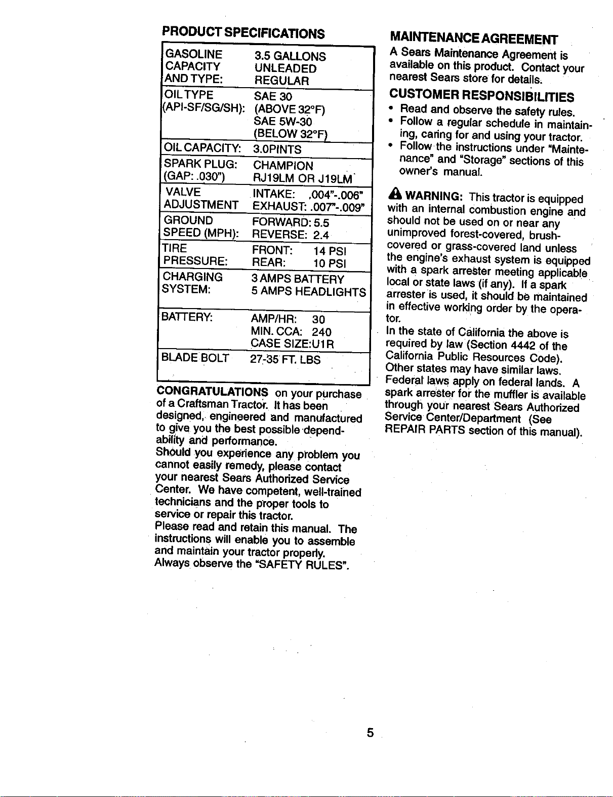
PRODUCT SPECIFICATIONS
GASOLINE
CAPACITY
AND TYPE:
OILTYPE
API-SF/BG/SH):
OIL CAPACITY:
SPARK PLUG:
(GAP: .030")
VALVE
ADJUSTMENT
GROUND
SPEED (MPH):
TIRE
PRESSURE:
CHARGING
SYSTEM:
3.5 GALLONS
UNLEADED
REGULAR
SAE 30
(ABOVE 32°F)
SAE 5W-30
(BELOW 32°FI
3.0PINTS
CHAMPION
RJ19LM OR J19LM
INTAKE: ,004"-.006"
EXHAUST'..007"-.009"
FORWARD: 5.5
REVERSE: 2.4
FRONT: 14 PSI
REAR: 10 PSI
3 AMPS BATTERY
5 AMPS HEADLIGHTS
BATFERY: AMP/HR: 30
MIN. CCA: 240
CASE SIZE:U1R
BLADE BOLT 27-35 FT. LBS
i
CONGRATULATIONS on your purchase
of a Craftsman Tractor. It has been
designed, engineered and manufactured
to give you the best possible depend-
ability and performance.
ShOuld you experience any problem you
cannot easily remedy, please contact
your nearest Sears Authorized Service
Center. We have competent, well-trained
technicians and the proper tools to
service or repair this tractor.
Please read and retain this manual. The
instructions will enable you to assemble
and maintain your tractor properly.
Always observe the "SAFETY RULES".
MAINTENANCE AGREEMENT
A Sears Maintenance Agreement is
available on this product. Contact your
nearest Sears store for details;
CUSTOMER RESPONSIBILITIES
• Read and observe the safety rules.
• Follow a regular schedule in maintain-
ing, caring for and using your tractor:
• Follow the instructionsunder =Mainte-
nance" and "Storage" sections of this
owner's manual.
WARNING: This tractor is equipped
with an internal combustion engine and
should not be used on or near any
unimproved forest-covered, brush-
covered or grass-covered land unless
the engine's exhaust system is equipped
with a spark arreSter meeting applicable
local or state laws (if any). If a spark
arrester is useo, it should be maintained
in effective working order by the opera-
tor.
In the state of California the above is
required by law (Section 4442 of the
California Public Resources Code).
Other states may have similar laws.
Federat laws apply on federal lands. A
spark arrester for the muffler is available
through your nearest Sears Authorized
Service Center/Department (See
REPAIR PARTS section of this manual).
5
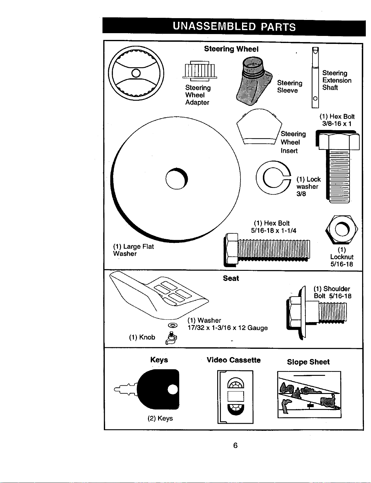
©
Steering Wheel
Steering
Wheel
Adapter
Steering
Sleeve
Wheel
Insert
t teering
Extension
Shaft
(1) Hex Bolt
3/8-16 x 1
0
(1) Lock
washer
3/8
(1) Large Flat
Washer
(1) Hex Bolt
5/16-18 x 1-1/4
@
(1)
Locknut
5/16-18
sher Seat
17/32 x 1-3/16 x 12 Gauge
(1) Knob j_
(T,-J
(1) Shoulder
Bolt 5/16-18
Keys
(2) Keys
Video Cassette
Slope Sheet
6
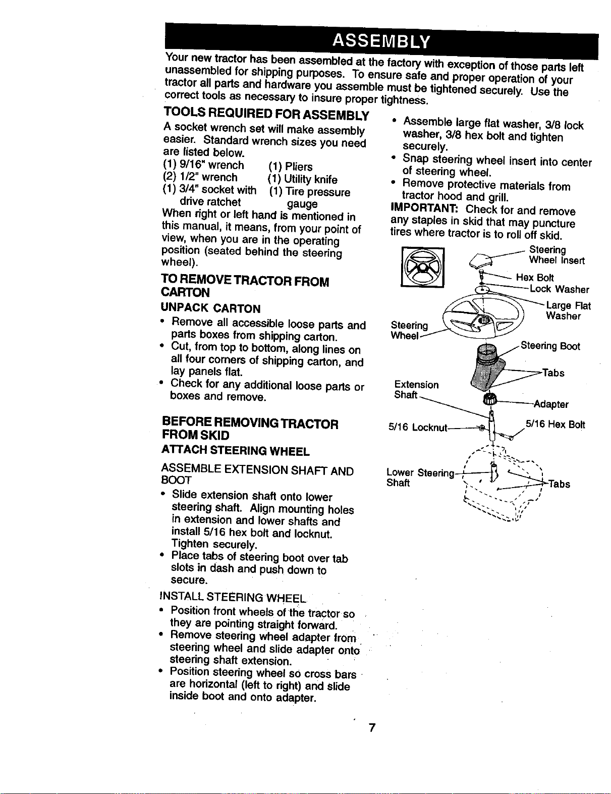
Your new tractor has been assembled at the factory with exception of those parts left
unassembled for shipping purposes. To ensure safe and proper operation of your
tractor all parts and hardware you assemble must be tightened securely. Use the
correct tools as necessary to insure proper tightness.
TOOLS REQUIRED FOR ASSEMBLY
A socket wrench set will make assembly
easier. Standard wrench sizes you need
are listed below.
(1) 9/16" wrench (1) Pliers
(2) 1/2" wrench (t) Utility knife
(1) 3/4" socket with (1) Tire pressure
drive ratchet gauge
When right or left hand is mentioned in
this manual, it means, from your point of
view, when you are in the operating
position (seated behind the steering
wheel).
TO REMOVE TRACTOR FROM
CARTON
UNPACK CARTON
• Remove all accessible loose parts and
parts boxes from shipping carton.
• Cut, from top to bottom, along lines on
all four comers of shipping carton, and
lay panels flat.
• Check for any additional loose parts or
boxes and remove.
BEFORE REMOVING TRACTOR
FROM SKID
ATTACH STEERING WHEEL
ASSEMBLE EXTENSION SHAFT AND
BOOT
• Slide extension shaft onto lower
steering shaft. Align mounting holes
in extension and lower shafts and
install 5/16 hex bolt and Iocknut.
Tighten securely.
• Place tabs of steering boot over tab
slots in dash and push down to
secure.
• Assemble large flat washer, 3/8 lock
washer, 3/8 hex bolt and tighten
securely,
• Snap steering wheel insert into center
of steering wheel.
• Remove protective materials from
tractor hood and grill.
IMPORTANT: Check for and remove
any staples in skid that may puncture
tires where tractor is to roll oft skid.
Steering
_lJ Wheel insert
Hex Bolt
---------Lock Washer
_ arge Flat
Washer
Boot
Extension
Shaft _ 5/16 Hex Bolt
5116 Locknut-_ ._/"
# ". •
Lower Steering _ t
Shaft ?. ,j__', Tabs
INSTALL STEERING WHEEL
• Position front wheels of the tractor so
they are pointing straight forward.
• Remove steering wheel adapter trom
steering wheel and slide adapter onto
steering shaft extension.
• Position steering wheel sO cross bars
are horizontal (left to right) and slide
inside boot and onto adapter.
7
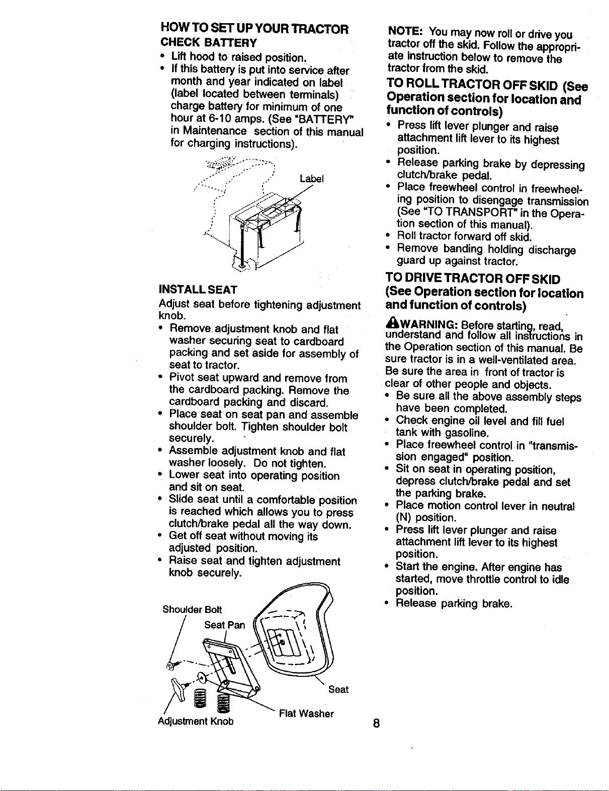
HOW TO SET UP YOUR TRACTOR
CHECK BATTERY
• Lift hood to raised position.
• If this battery isput into service after
month and year indicated on label
(label located between terminals)
charge battery for minimum of one
hour at 6-10 amps. (See =BATTERY"
in Maintenance section of this manual
for charging instructions).
"'" "°' ' Label
INSTALL SEAT
Adjust seat before tightening adjustment
knob.
• Remove• adjustment knob and flat
washer securing seat to cardboard
packing and set aside for assembly of
seat to tractor.
• Pivot seat upward and remove from
the cardboard packing. Remove the
cardboard packing and discard.
• Place seat on seat pan and assemble
shoulder bo_t. Tighten shoutder bolt
securely.
• Assemble adjustment knob and flat
washer loosely. Do not tighten.
• Lower seat into operating position
and sit on seat.
• Slide seat until a comfortable position
is reached which allows you to press
clutch/brake pedal all the way down.
• Get off seat without moving its
adjusted position.
• Raise seat and tighten adjustment
knob securely.
Shoulder Bolt
Seat Pan
NOTE: You may now rollor drive you
tractor off the skid. Follow the appropri-
ate instruction below to remove the
tractor from the skid,
TO ROLLTRACTOR OFF SKID (See
Operation section for location and
function of controls)
• Press lift lever plunger and raise
attachment liftlever to its highest
position.
• Release parking brake by depressing
clutch/brake pedal.
• Place freewheel control in freewheel-
ing position to disengage transmission
(See "TO TRANSPORT* in the Opera-
tion section of this manual).
• Roll tractor forward off skid.
• Remove banding holding discharge
guard up against tractor.
TO DRIVE TRACTOR OFF SKID
(See Operation section for location
and function of controls)
[!ILWARNING: Before starting, read,
understand and follow all instructions in
the Operation section of this manual. Be
sure tractor is in a well-ventilated area.
Be sure the area in front of tractor is
clear of other people and objects,
• Be sure all the above assembly steps
have been completed.
• Check engine oil level and fill fuel
tank with gasoline.
• Place freewheel control in "transmis-
sion engaged" position.
• Sit on seat in operating position,
depress clutch/brake pedal and set
the parking brake.
• Place motion control lever in neutral
(N) position.
• Press lift lever plunger and raise
attachment lift lever to its highest
position.
• Start the engine. After engine has
started, move throttle control to idle
position.
• Release parking brake.
Adjustment Knob
Seat
Flat Washer
8
• Slowly move the motion control lever
forward and slowly drive tractor off
skid.
• Apply brake to stop tractor, set parking
brake and place motion control lever
in neutral position.
° Turn ignition key to "OFF" position.
Continue with the instructions that follow.
CHECK TIRE PRESSURE
The tires on your tractor were overin-
flated at the factory for shipping pur-
poses. Correct tire pressure is important
for best cutting performance.
• Reduce tire pressure to PSI shown in
=PRODUCT SPECIFICATIONS"
section of this manual.
CHECK DECK LEVELNESS
For best cutting results, mower housing
should be properly leveled. See "TO
LEVEL MOWER HOUSING" in the
Service and Adjustments section of this
manual.
CHECK FOR PROPER POSITION
OF ALL BELTS
See the figures that are shown for
replacing motion and mower blade drive
belts in the Service and Adjustments
section of this manual. Verify that the
belts are routed correctly,
CHECK BRAKE SYSTEM
After you learn how to operate your
tractor, check to see that the brake is
propedy adjusted_ See =TO ADJUST
BRAKE" in the Service and Adjustments
section of this manual.
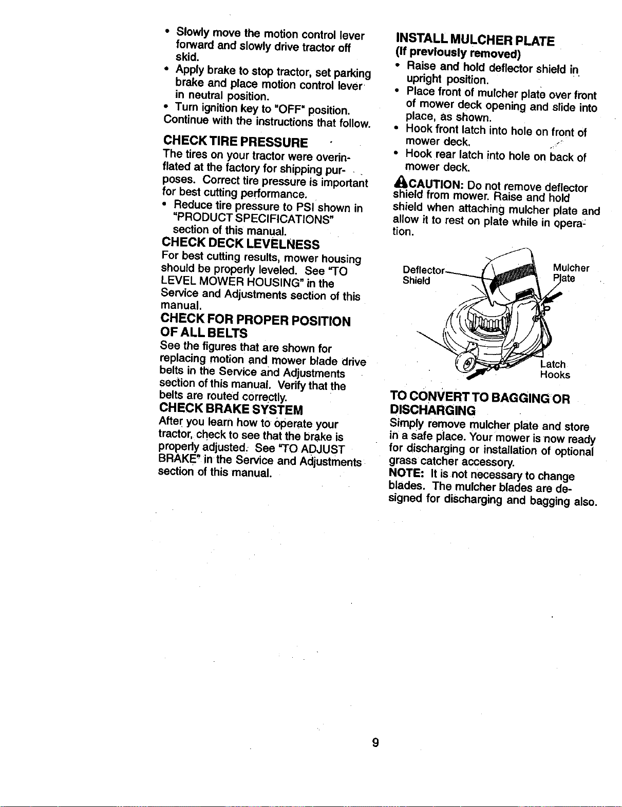
INSTALL MULCHER PLATE
(If previously removed)
• Raise and hold deflector shield in
upright position.
• Place front of mutcher plate over front
of mower deck opening and slide into
place, as shown.
• Hook front latch into hole on front of
mower deck. ,,_'_
• Hook rear latch into hole on back of
mower deck.
_CAUTION: Do not remove deflector
shield from mower. Raise and hold
shield when attaching mutcher plate and
allow it to rest on plate while in opera-
tion.
Shield
Mulcher
Latch
Hooks
TO CONVERT TO BAGGING OR
DISCHARGING
Simply remove mulcher plate and store
in a safe place. Your mower isnow ready
for discharging or installation of optional
grass catcher accessory.
NOTE: It is not necessary to change
blades. The mulcher blades are de-
signed for discharging and bagging also.
9
_CHECKLIST
BEFORE YOU OPERATE AND ENJOY
YOUR NEW TRACTOR, WE WISH TO
ASSURE THAT YOU RECEIVE THE
BEST PERFORMANCE AND
SATISFACTION FROM THIS QUALITY
PRODUCT,
PLEASE REVIEWTHE FOLLOWING
CHECKLIST:
•/ All assembly instructions have been
completed.
/ No remaining loose parts in carton.
4" Battery is properly prepared and
charged. (Minimum 1 hour at 6
amps).
/ Seat is adjusted comfortably and
tightened securely.
•/ All tires are properly inflated. (For
shipping purposes, the tires were
overinflated at the factory).
,f Be sure mower deck is properly
leveled side-to-side/front-to-rear for
best cutting results. (Tires must be
properly inflated for leveling).
,/Check mower and drive belts. Be sure
they are routed properly around
pulleys and inside all belt keepers.
,/Check wiring. See that all connections
are still secure and wires are properly
clamped,
/ Before driving tractor, be sure free-
wheel control is in drive position.
WHILE LEARNING HOW TO USE YOUF
TRACTOR, PAY EXTRAATTENTION TC
THE FOLLOWING IMPORTANT ITEMS:
/ Engine oil is at proper level.
•/ Fuel tank is filled with fresh, clean,
regular unleaded gasoline.
,/Become familiar with all controls - th_
location and function. Operate them
before you start the engine.
,/Be sure brake system is in safe
operating condition.
,/It is important to purge the transmis-
sion before operating your tractor for
the first time. Follow proper starting
and transmission purging instructions
(See "TO START ENGINE" and
=PURGE TRANSMISSION" in the
Operation section of this manual).
10
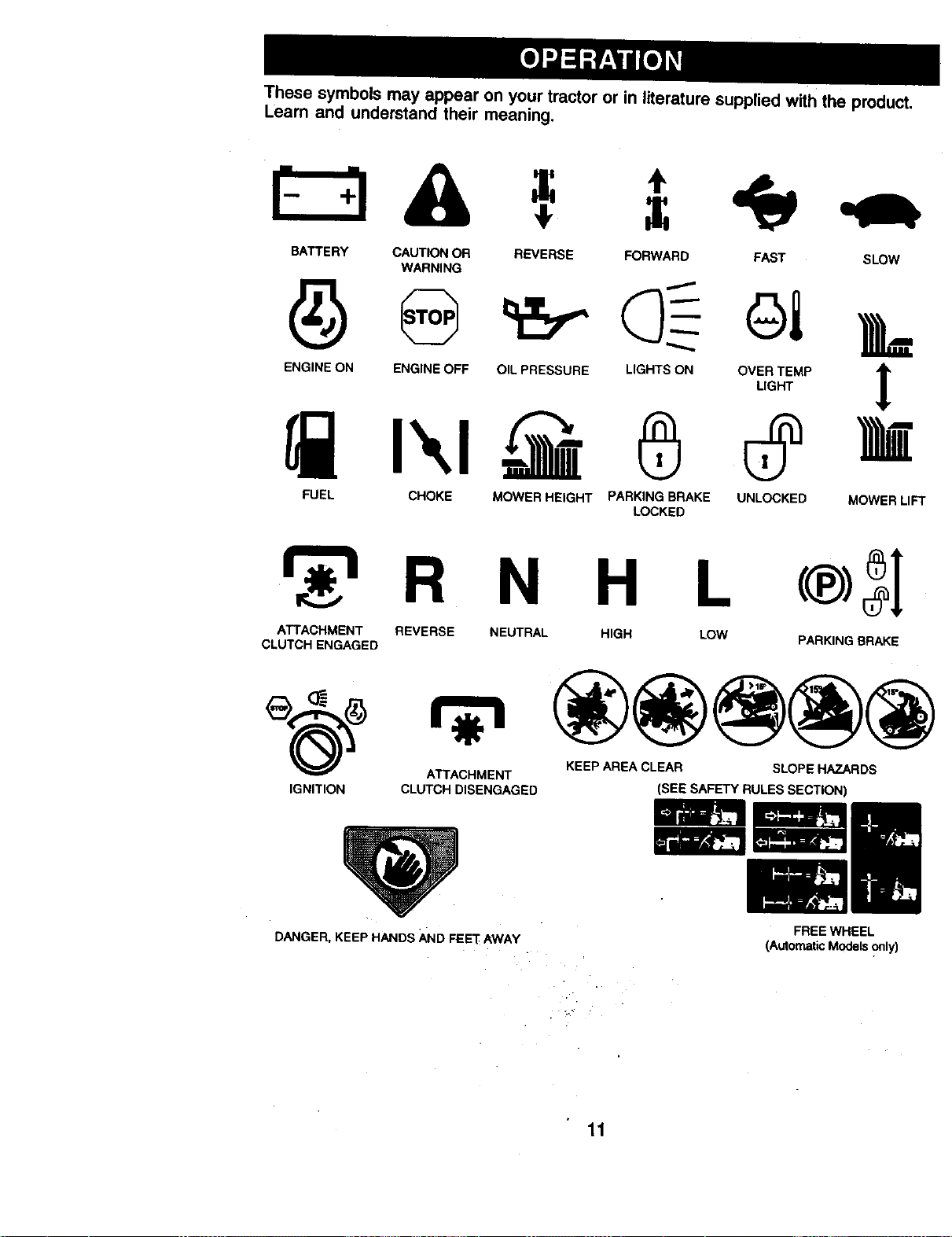
These symbols may appear on your tractor or in literature supplied with the product.
Leam and understand their meaning.
BATTERY CAUTION OR
WARNING
ENGINE ON ENGINE OFF
REVERSE FORWARD FAST SLOW
OIL PRESSURE
LIGHTS ON
6
FUEL CHOKE MOWER HEIGHT PARKING BRAKE UNLOCKED MOWER LIFT
LOCKED
R N H L
ATTACHMENT REVERSE NEUTRAL HIGH LOW
CLUTCH ENGAGED PARKING BRAKE
ATTACHMENT KEEP AREA CLEAR SLOPE HAZARDS
IGNITION CLUTCH DISENGAGED (SEE SAFETY RULES SECTION)
DANGER, KEEP HANDS AND FEE'["AWAY
FREE WHEEL
(Automatic Models _nly)
11
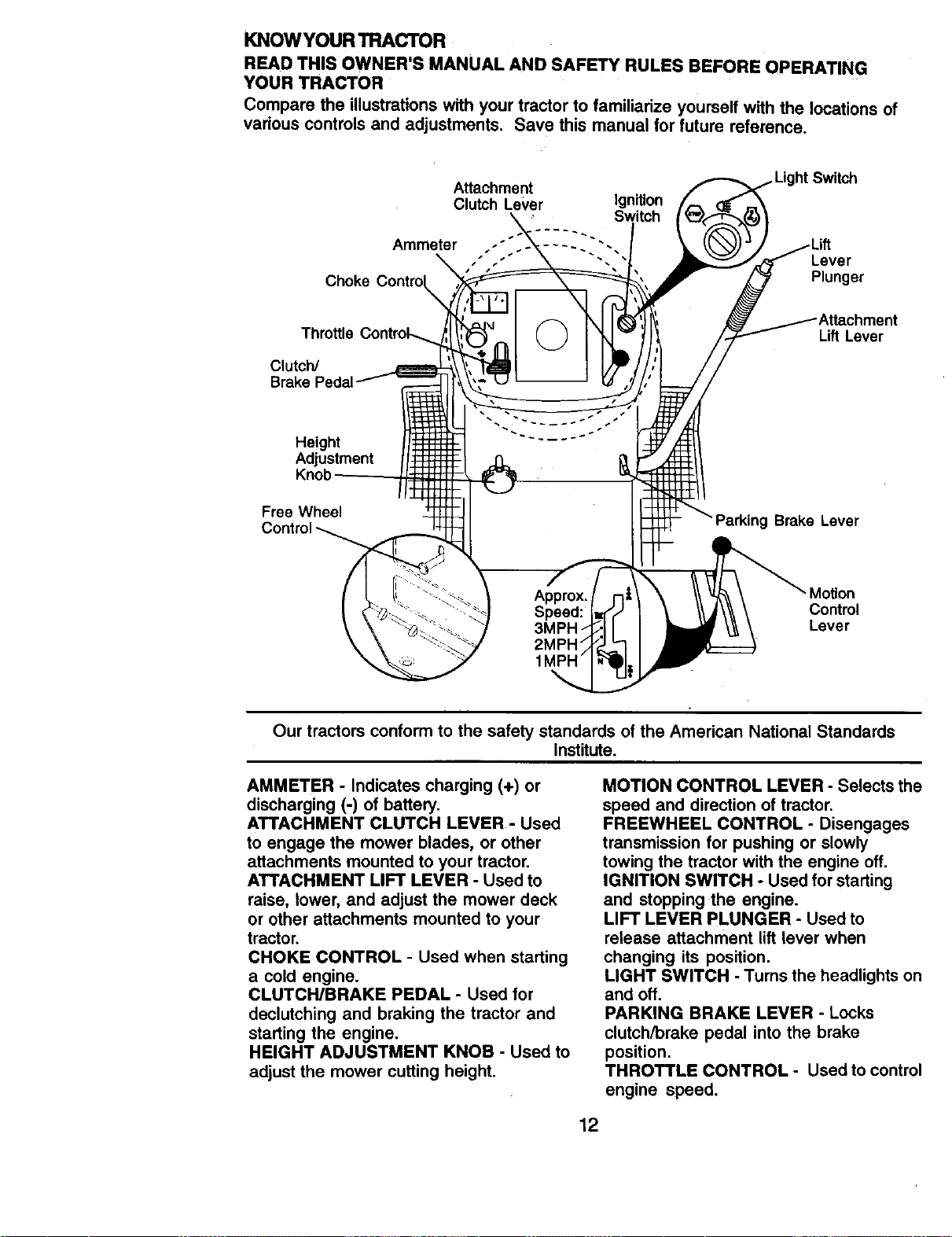
KNOWYOURTRACTOR
READ THIS OWNER'S MANUAL AND SAFETY RULES BEFORE OPERATING
YOUR TRACTOR
Compare the illustrations with your tractor to familiarize yourself with the locations of
various controls and adjustments. Save this manual for future reference.
Attachment
Clutch Lever Ignition
Switch
Ammeter .... .. • • •
Lever
Choke Plunger
Throttle
Clutch/
Lift Lever
Height
Adjustment
Knob
Free Wheel
Brake Lever
Moron
Control
Lever
Our tractors conform to the safety standards of the American National Standards
Institute.
AMMETER - Indicates charging (+) or
discharging (-) of battery.
ATTACHMENT CLUTCH LEVER - Used
to engage the mower blades, or other
attachments mounted to your tractor.
ATTACHMENT LIFT LEVER - Used to
raise, lower, and adjust the mower deck
or other attachments mounted to your
tractor.
CHOKE CONTROL - Used when starting
a cold engine.
CLUTCH/BRAKE PEDAL - Used for
declutching and braking the tractor and
starting the engine.
HEIGHT ADJUSTMENT KNOB - Used to
adjust the mower cutting height.
MOTION CONTROL LEVER - Selects the
speed and direction of tractor.
FREEWHEEL CONTROL - Disengages
transmission for pushing or slowly
towing the tractor with the engine off,
IGNITION SWITCH - Used for starting
and stopping the engine.
LIFT LEVER PLUNGER - Used to
release attachment lift lever when
changing its position.
LIGHT SWITCH - Turns the headlights on
and off.
PARKING BRAKE LEVER - Locks
clutch/brake pedal into the brake
position.
THROTTLE CONTROL - Used to control
engine speed.
12
The operation of any tractor can result in foreign objects thrown into
the eyes. which can result in severe eye damage. Always wear safety
glasses or eye shields while operating your tractor or performing any
adjustments or repairs. We recommend a wide vision safety,mask
over spectacles or standard safety glasses.
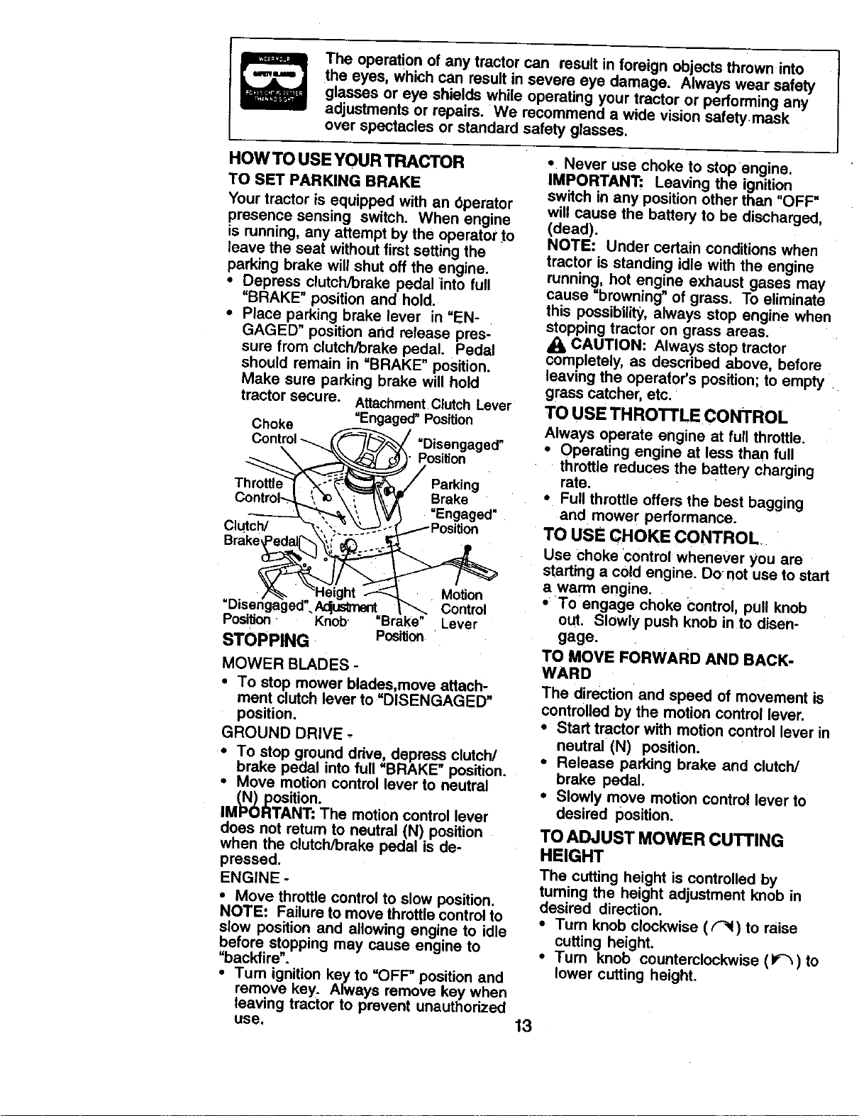
HOW TO USE YOUR TRACTOR
TO SET PARKING BRAKE
Your tractor is equipped with an Operator
presence sensing switch. When engine
is running, any attempt by the operator to
leave the seat without first setting the
parking brake will shut off the engine.
• Depress clutch/brake pedal into full
"BRAKE" position and hold.
• Place parking brake lever in "EN-
GAGED" position and release pres-
sure from clutch/brake pedal. Pedal
should remain in "BRAKE" position.
Make sure parking brake will hold
tractor secure. Attachment Clutch Lever
Choke =Engaged" Position
=Disengaged"
Position
Throttk
Brake
=Engaged"
Clutch/
=Disen
Position. Knob. =Brake"
STOPPING Position
Motion
Control
Lever
MOWER BLADES -
• To stop mower blades,move attach-
ment clutch lever to =DISENGAGED"
position.
GROUND DRIVE -
To stop ground drive, depress clutch/
i brake into full "BRAKE
pedal
position.
Move motion control lever to neutral
(N) position.
IMPORTANT: The motion control lever
does not return to neutral (N) position
when the clutch/brake pedal is de-
pressed.
ENGINE -
• Move throttle control to slow position.
NOTE: Failure to move throttle control to
slow position and allowing engine to idle
before stopping may cause engine to
=backfire".
•Tum ignition key to "OFF" position and
remove key. Always remove key when
leaving tractor to prevent unauthorized
use.
• Never use choke to stop engine.
IMPORTANT: Leaving the ignition
switch in any position other than "OFF"
will cause the battery to be discharged,
(dead).
NOTE: Under certain conditions when
tractor is standing idle with the engine
running, hot engine exhaust gases may
cause "browning" of grass. To eliminate
this possibility, always stop engine when
stopping tractor on grass areas.
dl_ CAUTION: Always stop tractor
completely, as described above, before
leaving the operator's position; to empty
grass catcher, etc.
TO USE THRO'n'LE CONTROL
Always operate engine at full throttle.
• Operating engine at less than full
throttle reduces the battery charging
rate.
• Full throttle offers the best bagging
and mower performance.
TO USE CHOKE CONTROL
Use choke control whenever you are
starting a cold engine. Do not use to start
a warm engine.
• To engage choke control, pull knob
out. Slowly push knob in to disen-
gage.
TO MOVE FORWARD AND BACK-
WARD
The direction and speed of movement is
controlled by the motion control lever.
• Start tractor with motion control lever in
neutral (N) position.
• Release parking brake and clutch/
brake pedal.
• Slowly move motion control lever to
desired position.
TO ADJUST MOWER CUTTING
HEIGHT
The cutting height is controlled by
turning the height adjustment knob in
desired direction.
• Turn knob clockwise ( _ ) to raise
cutting height.
• Turn knob countemleckwise (If_) to
lower cutting height.
13
The cutting height range is approxi-
mately 1-1/2" to 4". The heights are
measured from the ground to the blade
tip with the engine not running. These
heights are approximate and may vary
depending upon soil conditions, height
of grass and types of grass being
mowed.
• The average lawn should be cut to
approximately 2-1/2 inches during the
cool season and to over 3 inches
during hot months. For healthier and
better looking lawns, mow often and
after moderate growth.
• For best cutting performance, grass
over 6 inches in height should be
mowed twice. Make the first cut
relatively high; the second to desired
height.
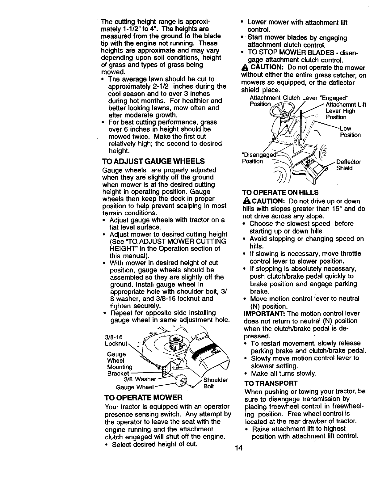
TO ADJUST GAUGE WHEELS
Gauge wheels are properly adjusted
when they are slightly off the ground
when mower is at the desired cutting
height in operating position. Gauge
wheels then keep the deck in proper
position to help prevent scalping in most
terrain conditions.
• Adjust gauge wheels with tractor on a
fiat level surface.
• Adjust mower to desired cutting height
(See TO ADJUST MOWER CUTTING
HEIGHT" in the Operation section of
this manual).
• With mower in desired height of cut
position, gauge wheels should be
assembled so they are slightly off the
ground. Install gauge wheel in
appropriate hole with shoulder bolt, 3/
8 washer, and 3/8-16 Iocknut and
tighten securely.
• Repeat for opposite side installing
gauge wheel in same adjustment hole.
3/8-16
Locknut_
Gauge
Wheel
Mounting
Bracket
Gauge Wheel
3houlder
Bolt
TO OPERATE MOWER
Your tractor is equipped with an operator
presence sensing switch. Any attempt by
the operator to leave the seat with the
engine running and the attachment
clutch engaged will shut off the engine.
• Select desired height of cut.
• Lower mower with attachment lift
control.
• Start mower blades by engaging
attachment clutch control.
• TO STOP MOWER BLADES - disen-
gage attachment clutch control.
CAUTION: Do not operate the mower
without either the entire grass catcher, on
mowers so equipped, or the deflector
shield place.
Attachment Clutch Lever "Engaged"
Position Lift
Lever High
Position
,':_:'_ Low
Position
Position
Shield
TO OPERATE ON HILLS
_CAUTION: Do not drive up or down
hills with slopes greater than 15 ° and do
not drive across any slope.
• Choose the slowest speed before
starting up or down hills.
• Avoid stopping or changing speed on
hills.
• If slowing is necessary, move throttle
control lever to slower position.
• If stopping is absolutely necessary,
push clutch/brake pedal quickly to
brake position and engage parking
brake.
• Move motion control lever to neutral
(N) position.
IMPORTANT: The motion control lever
does not return to neutral (N) position
when the clutch/brake pedal is de-
pressed.
• To restart movement, slowly release
parking brake and clutch/brake pedal.
• Slowly move motion control lever to
slowest setting.
• Make all turns slowly.
TO TRANSPORT
When pushing or towing your tractor, be
sure to disengage transmission by
placing freewheel control in freewheel-
ing position. Free wheel control is
located at the rear drawbar of tractor.
• Raise attachment lift to highest
position with attachment lift control.
14
• Pull freewheel control out and down
into the slot and release so it is held in
the disengaged position.
• Do not push or tow tractor at more
than two (2) MPH.
• To reengage transmission, reverse
above procedure.
NOTE: To protect hood from damage
when transporting your tractor on a truck
or a trailer, be sure hood is closed and
secured to tractor. Use an appropriate
means of tying hood to tractor (rope,
cord, etc.).
TOWING CARTS AND OTHER
A'n'ACHMENTS
Tow only the attachments that are
recommended by and comply with
specifications of the manufacturer of your
tractor. Use common sense when towing.
Too heavy of a load, while on a slope, is
dangerous. Tires can lose traction with
the ground and cause you to lose control
of your tractor.
BEFORE STARTING THE ENIGNE
CHECK ENGINE OIL LEVEL
• The engine in your tractor has been
shipped, from the factory, already filled
with summer weight oil.
• Check engine oil with tractor on level
ground.
• Remove oil fill cap/dipstick and wipe
clean, reinsert the dipstick and screw
cap tight, wait for a few seconds,
remove and read oil level. If neces-
sary, add oil until =FULL" mark on
dipstick is reached. Do not overfill.
• For cold weather operation you should
change oil for easier starting (See "OIL
VISCOSITY CHART" in the Mainte-
nance section of this manual).
• To change engine oil, see the Mainte:
nance section in this manual.
ADD GASOLINE
• Fill fuel tank. Use fresh, clean, regular
unleaded gasoline with a minimum of
87 octane. (Use of leaded gasoline
will increase carbon and lead oxide
deposits and reduce valve life). Do
not mix oil with gasoline. Purchase
fuel in quantities that can be used
within 30 days to assure fuel fresh-
ness,
IMPORTANT: When operating in
temperatures below 32°F(0°C), use
fresh, clean winter grade gasoline to
help insure good cold weather starting.
_1, WARNING: Experience indicates that
alcohol blended fuels (called gasohol or
using ethanol or methanol) can attract
moisture which leads to separation and
formation of acids during storage. Acidic
gas can damage the fuel system of an
engine while in storage. To avoid engine
problems, the fuel system should be
emptied before storage of 30 days or
longer. Drain the gas tank, start the
engine and let it run until the fuel lines
and carburetor are empty. Use fresh fuel
next season. See Storage Instructions
for additional information. Never use
engine or carburetor cleaner products in
the fuel tank or permanent damage may
occur.
A CAUTION: Fill to bottom of gas tank
filler neck. Do not overfill. Wipe off any
spilled oil or fuel. Do not store, spill or
use gasoline near an open flame.
TO START ENGINE
When starting the engine for the first time
or if the engine has run out of fuel, it will
take extra cranking time to move fuel
from the tank to the engine.
• Be sure freewheel control is in the
transmission engaged position.
• Sit on seat in operating position,
depress clutch/brake pedal and set
parking brake.
• Place motion control lever in neutral
(N) position.
• Move attachment clutch to "DISEN-
GAGED" position.
• Move throttle control to fast position
• Pull choke control out for a cold
engine start attempt. For a warm
engine start attempt the choke control
. may not be needed.
NOTE: Before starting, read the warm
and cold starting procedures below.
15
• Insert key into ignition and turn key
clockwise to =START" position and
release key as soon as engine starts.
Do not run starter continuously for
more than fifteen seconds per minute.
If the engine does not start after
several attempts, push choke control
in, wait a few minutes and try again. If
engine still does not start, pull the
choke control out and retry.
WARM WEATHER STARTING (50 ° F and
above)
• When engine starts, slowly push
choke control in until the engine
begins to run smoothly. If the engine
starts to run roughly, pull the choke
control out slightly for a few seconds
and then continue to push the control
in slowly.
• The attachments and ground drive can
now be used. If the engine does not
accept the load, restart the engine and
allow it to warm up for one minute
using the choke as described above.
COLD WEATHER STARTING (50 ° F and
below)
• When engine starts, slowly push
choke control in until the engine
begins to run smoothly. Continue to
push the choke control in small steps
allowing the engine to accept small
changes in speed and load, until the
choke control is fully in. If the engine
starts to run roughly, pull the choke
control out slightly for a few seconds
and then continue to push the control
in slowly. This may require an engine
warm-up period from several seconds
to several minutes, depending on the
temperature.
AUTOMATIC TRANSMISSION WARM UP
• Before driving the unit in cold weather,
the transmission should be warmed up
as follows:
• Be sure the tractor is on level
ground.
• Place the motion control lever in
neutral. Release the parking brake
and let the clutch/brake
slowly return to operating position.
• Allow one minute for transmission to
warm up. This can be done during
the engine warm up period.
• The attachments can be used during
the engine warm-up period after the
transmission has been warmed up
and may require the choke control be
pulled out slightly.
NOTE: If at a high altitude (above 3000
feet) or in cold temperatures (below 32
F) the carburetor fuel mixture may need
to be adjusted for best engine perfor-
mance. See "TO ADJUST CARBURE-
TOR" in the Service and Adjustments
section of this manual.
PURGE TRANSMISSION
A CAUTION: Never engage or disen-
gage freewheel lever while the engine is
running.
To ensure proper operation and perfor-
mance, it is recommended that the
transmission be purged before operating
tractor for the first time. This procedure
will remove any trapped air reside the
transmission which may have developed
during shipping of your tractor.
IMPORTANT: Should your transmission
require removal for service or replace-
ment, it should be purged after reinstalla-
tion before operating the tractor.
• Place tractor safely on level surface
with engine off and parking brake set.
• Disengage transmission by placing
freewheel control in freewheeling
position (See "TO TRANSPORT" in
this section of manual).
• Sitting in the tractor seat, start engine.
After the engine is running, move
throttle control to slow position. With
motion control lever in neutral (N)
position, slowly disengage clutch/
brake pedal.
• Move motion control lever to full
forward position and hold for five (5)
seconds. Move lever to full reverse
position and hold for five (5) seconds.
Repeat this procedure three (3) times.
NOTE: During this procedure there will
be no movement of drive wheels. The air
is being removed from hydraulic ddve
system.
• Move motion control lever to neutral
(N) position. Shut- off engine and set
parking brake.
• Engage transmission by placing
freewheel control in driving position
(See "TO TRANSPORT" in this section
of manual).
16
• Sitting in the tractor seat, start engine.
After the engine is running, move
throttle control to half (1/2) speed. With
motion control lever in neutral (N)
position, slowly disengage clutch/
brake pedal.
• Slowly move motion control lever
forward, after the tractor moves
approximately live (5) feet, slowly
move motion control lever to reverse
position. After the tractor moves
approximately five (5) feet return the
motion control lever to the neutral (N)
position. Repeat this procedure with
the motion control lever three (3)
times.
• Your tractor is now purged and now
ready for normal operation.
MOWING TIPS
• Mower should be properly leveled for
best mowing performance. See "TO
LEVEL MOWER HOUSING" in the
Service and Adjustments section of
this manual.
• The left hand side of mower should be
used for trimming.
• Drive so that clippings are discharged
onto the area that has been cut. Have
the outarea to the right of the tractor,
This will result in a more even distribu-
tion of clippings and more uniform
cutting.
• When mowing large areas, start by
turning to the dght so that clippings will
discharge away from shrubs, fences,
driveways, etc. After one or two
rounds, mow in the opposite direction
making left hand turns until finished.
• If grass is extremely tall, it should be
mowed twice to reduce load and
possible fire hazard from dried
clippings. Make first cut relatively
high; the second to the desired height.
• Do not mow grass when it is wet. Wet
grass will plug mower and leave
undesirable clumps. Allow grass to
dry before mowing.
• Always operate engine at full throttle
when mowing to assure better mowing
performance and proper discharge of
material. Regulate ground speed by
selecting a low enough gear to give
the mower cutting performance as well
as the quality of out desired.
• When operating attachments, select a
ground speed that will suit the terrain
and give best performance of the
attachment being used.
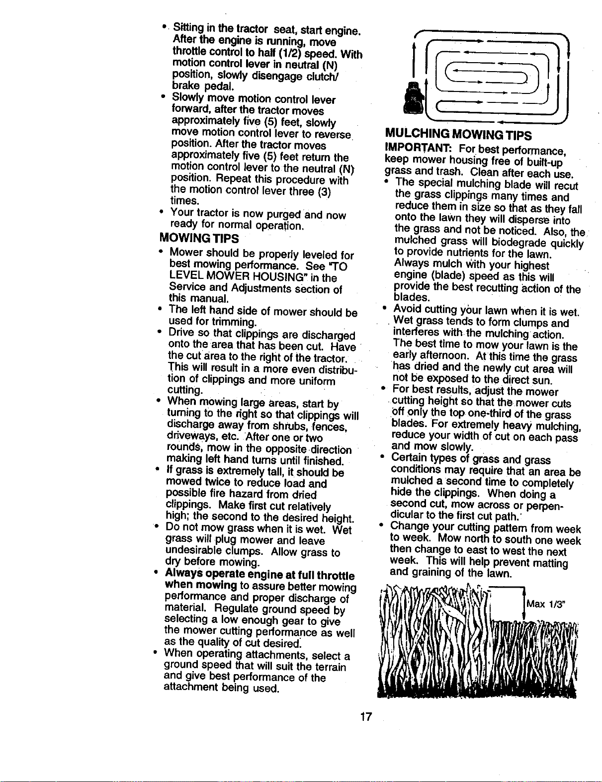
MULCHING MOWING TIPS
IMPORTANT: For best perton'nance,
keep mower housing free of built-up
grass and trash. Clean after each use.
• The special mulching blade will recut
the grass clippings many times and
reduce them in size so that as they fall
onto the lawn they will disperse into
the grass and not be noticed. Also, the
mulched grass will biodegrade quickly
to provide nutrients for the lawn.
Always mulch With your highest
engine (blade) speed as this will
provide the best recutting action of the
blades.
• Avoid cutting yOur lawn when it is wet.
. Wet grass tends to form clumps and
interferes with the mulching action.
The best time to mow your lawn is the
early afternoon. At this time the grass
has dried and the newly cut area will
not be exposed to the direct sun.
• For best results, adjust the mower
cutting height so that the mower cuts
Off only the top one-third of the grass
blades. For extremely heavy mulching,
reduce your width of cut on each pass
and mow slowly.
• Certain types of grass and grass
Conditions may require that an area be
mulched a second time to completely
hide the clippings. When doing a
second cut, mow across or perpen-
dicular to the first cut path.'
• Change your cutting pattern from week
to week. Mow north to south one week
then change to east to west the next
week. This will help prevent matting
and graining of the lawn.
17
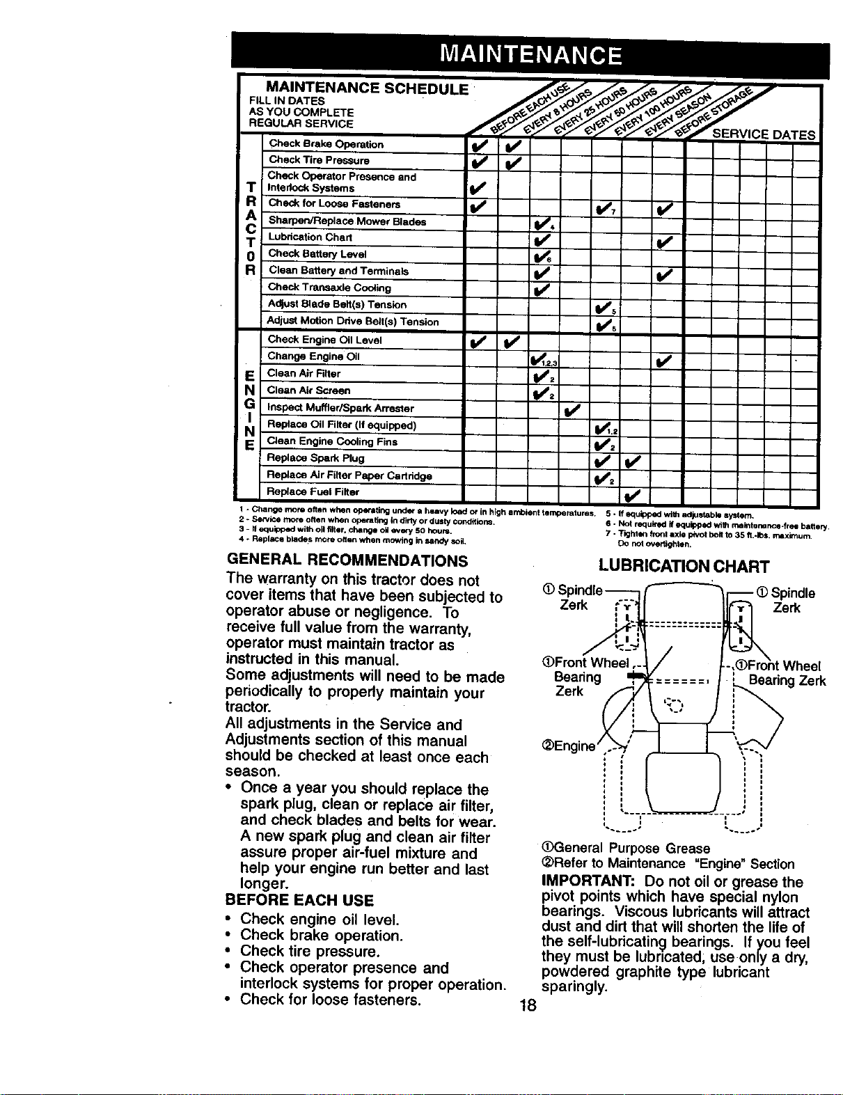
MAINTENANCE SCHEDULE
FILL IN DATES
AS YOU COMPLETE
REGULAR SERVICE SERVICE DATES
Check Brake Operation _ _
Check Tire Pressure
Check Operator Presence and
T Interlock Systems I_
Check for Loose Fasteners I_ 1_7 Id_
T Lubrication Chart _ V _
0 Check Battery Level
R Clean Battery and Terminels I_
Check Trarmaxle Cooling I_
Adlust Blade Belt(e) Tension II_s
Adjust Motion Drive Belt(s) Tension ll_s
Check Engine Oil Level V _ I_
Change Engine Oil _1,2,._ I_
E Clean Air Rlter _:
N Clean Air S_reen I
G Inspect Muffler/Spark Arrester
I
Replece Oil Filter (If equipped) =_.2
N Clean Engine Cooling Fins
Replace Spark Plug _= I_
Replace Air Filter Paper Cartridge _=
Replece Fuel Filter I_
1 - Change more often when opt-elf ng under a heavy load or in high ambient temperatures. 5 - If equipped with adju_dabfil syltem.
2 - Service more often when operaifng In _rty or dusty conditions. 6 ° Not required if equipped v_th mathte_rtce-free battery.
3 - If equipped with oil filter, chenge oil every 50 hours. 7 - Tighten _ronl axle pivot bolt to 35 ft.*los, mixbnum.
4 * Replace blades more onen when mowing in land'/soil. DO not overtighten.
GENERAL RECOMMENDATIONS
The warranty on this tractor does not
cover items that have been subjected to
operator abuse or negligence. To
receive full value from the warranty,
operator must maintain tractor as
instructed in this manual.
Some adjustments will need to be made
periodically to propedy maintain your
tractor.
All adjustments in the Service and
Adjustments section of this manual
should be checked at least once each
season.
• Once a year you should replace the
spark plug, clean or replace air filter,
and check blades and belts forwear.
A new spark plug and clean air filter
assure proper air-fuel mixture and
help your engine run better and last
longer.
BEFORE EACH USE
• Check engine oil level.
• Check brake operation.
• Check tire pressure.
• Check operator presence and
interlock systems for proper operation.
• Check for loose fasteners.
LUBRICATION CHART
Zerk Zerk
(i)Front Wheel ,-,
Bearing
Zerk
Beadng Ze_
(DGeneral Purpose Grease
(_Refer to Maintenance "Engine" Section
IMPORTANT: DO not oil or grease the
_ivot points which have special nylon
earings. Viscous lubricants will attract
dust and dirt that will shorten the life of
the self-lubricating bearings. If you feel
they must be lubncated; useonly a dry,
powdered graphite type lubricant
sparingly.
18
TRACTOR
Always .observe safety rules when
pedormmg any maintenance.
BRAKE OPERATION
Iftractor requires more than six (6) feet
stopping distance at high speed in
highestgear, then brake must be ,
adjusted. (See "TO ADJUST BRAKE" in
the Service and Adjustments section of
this manual).
TIRES
• Maintain proper air pressure in all tires
(See "PRODUCT SPECIFICATIONS"
section of this manual).
• Keep tires free of gasoline, oil, or
insect control chemicals which can
harm rubber.
• Avoid stumps, stones, deep ruts, sharp
objects and other hazards that may
cause tire damage.
NOTE: To seal tire punctures and
prevent flat tires due to slow leaks, tire
sealant may be purchased from your
local parts dealer. Tire sealant also
prevents tire dry rot and corrosion.
OPERATOR PRESENCE SYSTEM
Be sure operator presence and interlock
systems are working properly. If your
tractor does not function as descrifSed,
repair the problem immediately.
• The engine should not start unless the
clutch/brake pedal is fully depressed
and attachement clutch control is in
the disengaged position.
• When the engine is running, any
attempt by the operator to leave the
seat without first setting the parking
brake should shut off the engine.
• When the engine is running and the
attachment clutch is engaged, any
attempt by the operator to leave the
seat should shut off the engine:
• The attachment clutch should never
operate unless the operator is in the
seat.
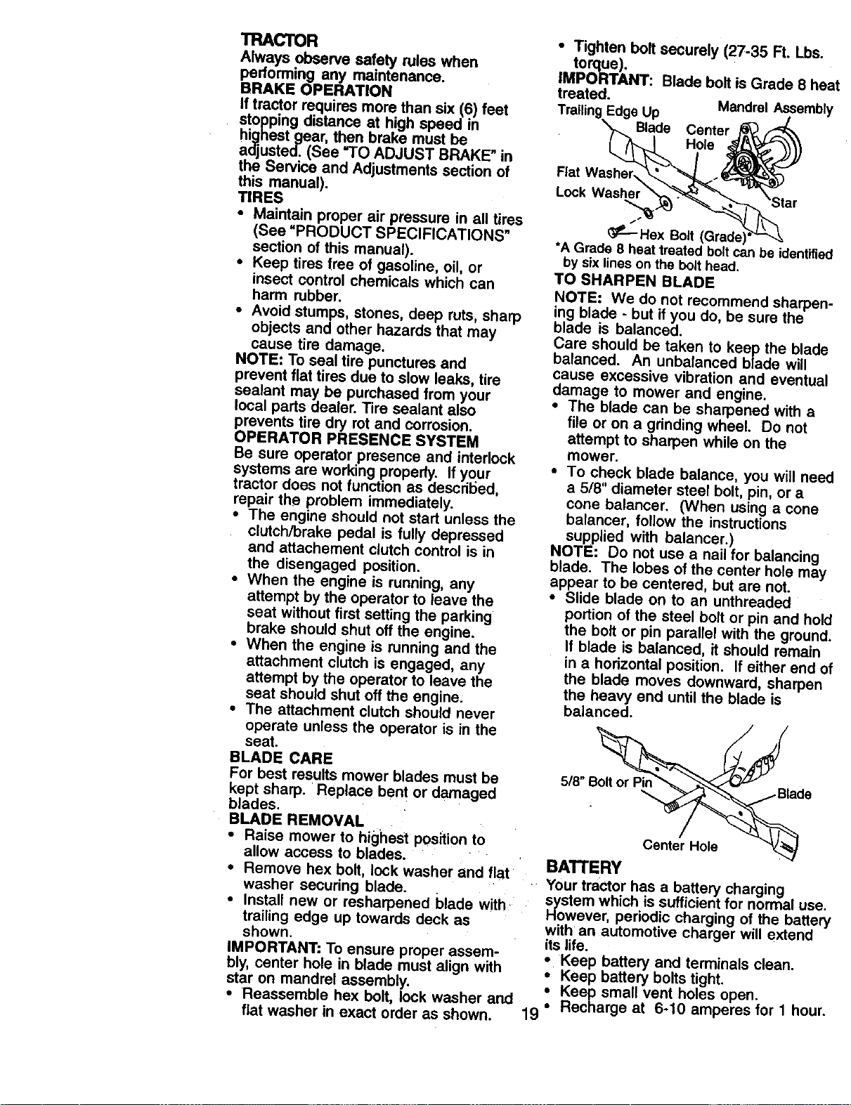
BLADE CARE
For best results mower blades must be
kept sharp. Replace bent or damaged
blades,
BLADE REMOVAL
• Raise mower to highest position to
allow access to blades.
• Remove hex bolt, lock washer and flat
washer secudng blade.
• Install new or resharpened blade with
trailing edge up towards deck as
shown.
IMPORTANT: To ensure proper assem-
bly, center hole in blade must align with
star on mandrel assembly.
• Reassemble hex bolt, lock washer and
flat washer in exact order as shown.
• Tighten bolt securely (27-35 R. Lbs.
torque).
IMPORTANT: Blade bolt is Grade 8 heal
treated.
Mandrel Assembly
Trailing Edge Up _ _/
Blade Center p_
Flat Washer_..._
Lock Washe,_"__ar
_--Hex Bolt (Grade)
*A Grade 8 heat treated boltcan be identified
by sixlines on the bolt head.
TO SHARPEN BLADE
NOTE: We do not recommend sharpen-
ing blade - but if you do, be sure the
blade is balanced.
Care should be taken to keep the blade
balanced. An unbalanced blade will
cause excessive vibration and eventual
damage to mower and engine.
• The blade can be sharpened with a
file or on a grinding wheel. Do not
attempt to sharpen while on the
mower.
• To check blade balance, you will need
a 5/8" diameter steel bolt, pin, or a
cone balancer. (When using a cone
balancer, follow the instructions
supplied with balancer.)
NOTE: Do not use a nail for balancing
blade. The lobes of the center hole may
appear to be centered, but are not.
• Slide blade on to an unthreaded
portion of the steel bolt or pin and hold
the bolt or pin parallel with the ground.
If blade is balanced, it should remain
in a horizontal position. If either end of
the blade moves downward, sharpen
the heavy end until the blade is
balanced.
5/8" _ __n_BLa6e.
Center Hole _!
BATTERY
Your tractor has a battery charging
_/oStem which is sufficient for normal use.
wever, periodic charging of the battery
with an automotive charger will extend
its life.
• Keep battery and terminals clean.
Keep battery bolts tight.
Keep small vent holes open.
Recharge at 6-10 amperes for 1 hour.
19
NOTE:Theodginalequipmentbatteryon
yourtractoris maintenancefree,Donot
attemptto openorremovecapsor
covers.Addingorcheckinglevelof
electrolyteis notnecessary.
TOCLEANBATTERYANDTERMINALS
Corrosionanddirtonthe batteryand
terminalscan causethebatteryto"leak"
power.
Remove terminal guard, i
Disconnect BLACK battery cable first
then RED battery cable and remove
battery from tractor.
• Rinse the battery with plain water and
dry.
• Clean terminals and battery cable
ends with wire brush until bright.
• Coat terminals with grease or petro-
leum jelly.
• Reinstall battery (See =REPLACING
BATTERY in the SERVICE AND
ADJUSTMENTS section of this
manual).
V-BELTS
Check V-belts for deterioration and wear
after 100 hours of operation and replace
if necessary. The belts are not adjustable,
Replace belts if they begin to slip from
wear.
TRANSAXLE COOLING
The transmission fan and cooling fins
should be kept clean to assure proper
cooling.
Do not attempt to clean fan or transmis-
sion while engine is running or while the
transmission is hot. To prevent possible
damage to seals, do not use high
pressure water or steam to clean
transaxle.
• Inspect cooling fan to be sure fan
blades are intact and clean.
• Inspect cooling fins for dirt, grass
clippings and other materials. To
prevent damage to seals, do not use
compressed air or hi_lh pressure
sprayer to clean coohng fins,
TRANSAXLE PUMP FLUID
The transaxle was sealed at the factory
and fluid maintenance is not required for
the life of the transaxle. Should the
transaxle ever leak or require servicing,
contact your nearest authorized service
center/department.
ENGINE
LUBRICATION
Only use high quality detergent oil rated
with API service classification SF, SG, or
SH. Select the oil's SAE viscosity grade
according to your expected operating
temperature.
NOTE: Although multi-viscosity oils
(5W30, 10W30 etc.) improve starting m
cold weather, these multi-viscosity oils
will result in increased oil consumption
when used above 32°F. Check your
engine oil level more frequently to avoid
possible engine damage from running
low on oil.
Change the oil after every 25 hours of
operation or at least once a year if the
tractor is not used for 25 hours in one
year•
Check the crankcase oil level before
starting the engine and after each eight
(8) hours of operation. Tighten oil fill cap/
dipstick securely each time you check
the oil level.
TO CHANGE ENGINE OIL
Determine temperature range expected
before oil change. All oil must meet API
service classification SF, SG or SH.
• Be sure tractor is on level surface.
• Oil will drain more freely when warm.
• Catch oil in a suitable container.
• Remove oil fill cap/dipstick. Be careful
not to allow dirt to enter the engine
when changing oil.
• Remove drain plug.
• After oil has drained completely,
replace oil drain plug and tighten
securely.
• Refill engine with oil through oil fill
dipstick tube. Pour slowly. Do not
overfill. For approximate capacity see
"PRODUCT SPECIFICATIONS"
section of this manual.
• Use gauge on oil fill cap/dipstick for
checking level. Be sure dipstick cap is
tightened securely for accurate
reading. Keep oil at "FULL" line on
dipstick.
Oil
Drain ,,,.'_--_ Air Screen
Plug _ .
OIL Fill Ca_
DJpstsick_
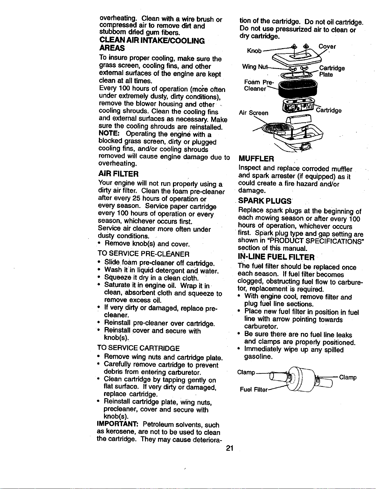
CLEAN AIR SCREEN
Air screen must be kept free of dirt and
chaff to prevent engine damage from
2O
overheating.Cleanwitha wirebrushor
compressedair to removedirtand
stubborndriedgumfibers.
CLEAN AIR INTAKE/COOUNG
AREAS
To insure proper cooling, make sure the
grass screen, cooling fins, and other
extemal surfaces of the engine are kept
clean at all times.
Every 100 hours of operation (mol'e often
under extremely dusty, dirty conditions),
remove the blower housing and other -
cooling shrouds. Clean the cooling fins
and external surfaces as necessary. Make
sure the cooling shrouds are reinstalled.
NOTE: Operating the engine with a
blocked grass screen, .dirty or plugged
cooling fins, and/or cooling shrouds
removed will cause engine damage due to
overheating.
AIR FILTER
Your engine will not run propedy using a
dirty air filler. Clean the foam pre-cleaner
after every 25 hours of operation or
every season. Service paper cartridge
every 100 hours of operation or every
season, whichever occurs first.
Service air cleaner more often under
dusty conditions.
• Remove knob(s) and cover.
TO SERVICE PRE-CLEANER
• Slide foam pre-cleaner off cartridge.
• Wash llin liquid detergent and water.
• Squeeze it dry in a clean cloth.
• Saturate it in engine oil, Wrap it in
clean, absorbent cloth and squeeze to
remove excess oil,
• ff very dirty or damaged, replace pre-
cleaner.
• Reinstall pre-cleaner over cartridge.
• Reinstall cover and secure with
knob(s).
TO SERVICE CARTRIDGE
• Remove wing nuts and cartddge plate.
• Carefully remove cartddge to prevent
debris from entering carburetor.
• Clean cartridge by tapping gently on
flat surface. If very dirty or damaged,
replace carfddge.
* Reinstall cartridge plate, wing nuts,
precleaner, cover and secure with
knob(s).
IMPORTANT" Petroleum solvents, such
as kerosene, are not to be used to clean
the cartridge. They may cause deteriora-
tion ofthe cadddge. Do not oilcadddge.
Do not use pressudzedairtodeanor
dry cadddge.
Cover
Wing
Foam Pre-
Plate
Air Screen
MUFFLER
Inspect and replace corroded muffler
and spark arrester (if equipped) as it
Could create a fire hazard and/or
damage.
SPARK PLUGS
Replace spark plugs at the beginning of
each mowing season or after every 100
hours of operation, whichever occurs
first. Spark plug type and gap setting am
shown in =PRODUCT SPECIFICATIONS"
section of this manual.
IN-LINE FUEL FILTER
The fuel filter should be replaced once
each season. If fuel filter becomes
clogged, obstructing fuel flow to carbure-
tor, replacement is required.
• With engine cool, remove filter and
plug fuel line sections,
• Place new fuel filler in position in fuel
line with arrow pointing towards
carburetor.
• Be sure there are no fuel line leaks
and clamps are propedy positioned.
• Immediately wipe up any spilled
gasoline.
21
CLEANING
i Clean engine, battery, seat finish etc.
°f all f° reign mauttr_r" h is
Keep fin'shed s aces and wee
free of all gasoline, oil, etc.
• Protect painted surfaces with automo-
tive type wax.
We do not recommend using a garden
hose to clean your tractor unless the
electrical system, muffler, air filter and
carburetor are covered to keep water out.
Water in engine can result in a short-
ened engine life.
,&CAUTION: Before performing any service or adjustments:
• Depress clutch/brake pedal fully and set parking brake.
• Place motion control lever in neutral (N) position.
• Place attachment clutch in "DISENGAGED" position.
• Turn ignition key =OFF" and remove key.
• Make sure the blades and all moving parts have completely stopped.
• Disconnect spark plug wire from spark plug and place wire where it cannot
come in contact with plug.
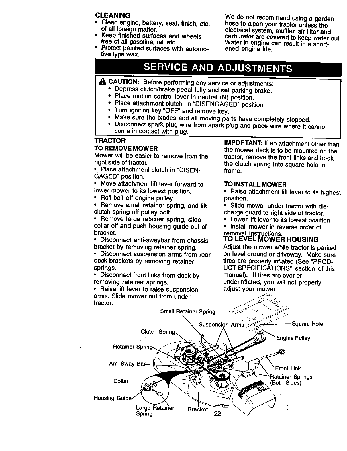
TRACTOR
TO REMOVE MOWER
Mower will be easier to remove from the
right side of tractor.
• Piece attachment clutch in =DISEN-
GAGED" position.
• Move attachment lift lever forward to
lower mower to its lowest position.
• Roll belt off engine pulley.
• Remove small retainer spring, and lift
clutch spdng off pulley bolt.
• Remove large retainer spring, slide
collar off and push housing guide out of
bracket.
• Disconnect anti-swaybar from chassis
bracket by removing retainer spring.
• Disconnect suspension arms from rear
deck brackets by removing retainer
springs.
• Disconnect front links from deck by
removing retainer springs.
• Raise lift lever to raise suspension
arms. Slide mower out from under
tractor.
Small Retainer Spring
IMPORTANT: If an attachment other than
the mower deck is to be mounted onthe
tractor, remove the front links and hook
the clutch spring into square hole in
frame.
TO INSTALL MOWER
• Raise attachment lift lever to its highes
position.
• Slide mower under tractor with dis-
charge guard to right side of tractor.
• Lower lift lever to its lowest position.
• Install mower in reverse order of
removal instructions.
TO LEVEL MOWER HOUSING
Adjust the mower while tractor is parked
on level ground or driveway. Make sure
tires are properly inflated (See =PROD-
UCT SPECIFICATIONS" section of this
manual). If tires are over or
underinflated, you will not properly
adjust your mower.
Arms ._;_',._._.-_Square Hole
ine Pulley
Retainer
Anti-Swa'
Link
Sides)
Housing
Large Retainer
Spring 22
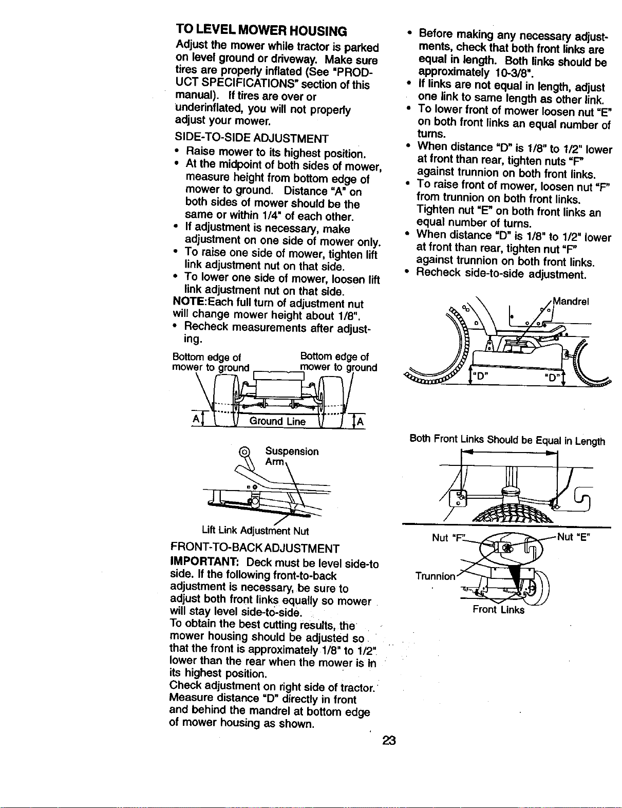
TO LEVEL MOWER HOUSING
Adjust the mower while tractor is parked
on level ground or driveway. Make sure
tires are propedy inflated (See =PROD-
UCT SPECIFICATIONS" section of this
manual). If tires are over or
underinflated, you will not properly
adjust your mower.
SIDE-TO-SIDE ADJUSTMENT
• Raise mower to its highest position.
• At the midpoint of both sides of mower,
measure height from bottom edge of
mower to ground. Distance "A" on
both sides of mower should be the
same or within 1/4" of each other.
• If adjustment is necessary, make
adjustment on one side of mower only.
• To raise one side of mower, tighten lift
link adjustment nut on that side.
• To lower one side of mower, loosen lift
link adjustment nut on that side.
NOTE:Each full turn of adjustment nut
will change mower height about 1/8".
• Recheck measurements after adjust-
ing.
Bottom edge of Bottom edge of
m°we_ °und
Suspension
Lift Link Adjustment Nut
FRONT-TO-BACK ADJUSTMENT
IMPORTANT: Deck must be level side-to
side. If the following front-to-back
adjustment is necessary, be sure to
adjust both front links equally so mower
will stay level side-to-side;
To obtain the best cutting results, the
mower housing should be adjusted so
that the front is approximately 1/8" to 1/2"
lower than the rear when the mower iS In
its highest position.
Check adjustment on right side of tractor.
Measure distance =D" directly in front
and behind the mandrel at bottom edge
of mower housing as shown,
23
• Before making any necessary adjust.
ments, check that both front links are
equal in length. Both links should b_
approximately 10-3/8 =.
• If links are not equal in length, adjust
one link to same length as other link.
• To lower front of mower loosen nut =E
on both front links an equal number <
turns.
• When distance =D" is 1/8" to 112"Iow_
at front than rear, tighten nuts "P
against trunnion on both front links.
• To raise front of mower, loosen nut =F
from trunnion on both front links.
Tighten nut "E" on both front links an
equal number of turns.
• When distance "D" is 1/8" to 1/2" Iow_
at front than rear, tighten nut "P
against trunnion on beth front links.
• Recheck side-to-side adjustment.
,Mandrel
"D" "D"
Both Front LinksShould be Equal in Length
Nut
=E"
Front Links
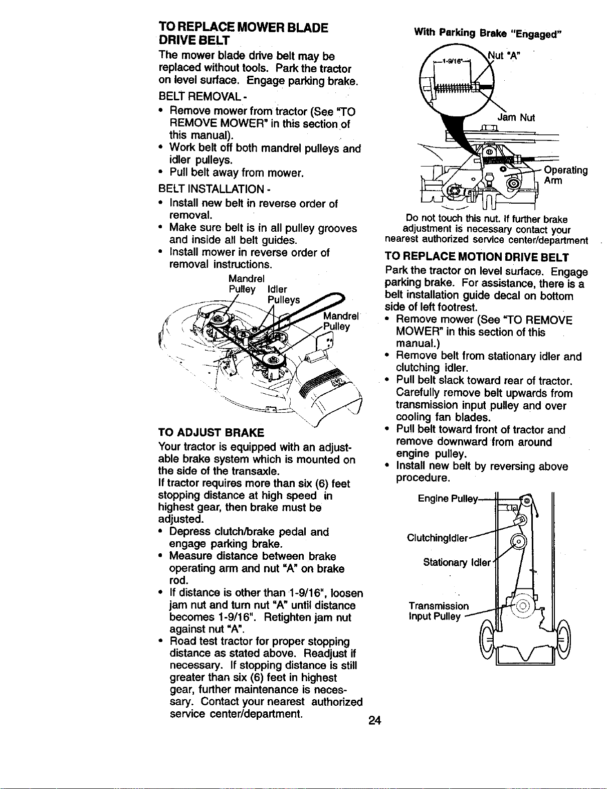
TO REPLACE MOWER BLADE
DRIVE BELT
The mower blade drive belt may be
replaced without tools, Park the tractor
on level sudace. Engage parking brake.
BELT REMOVAL -
• Remove mower from tractor (See "TO
REMOVE MOWER" in this section of
this manual).
• Work belt off both mandrel pulleys and
idler pulleys.
• Pull belt away from mower.
BELT INSTALLATION -
• Install new belt in reverse order of
removal.
• Make sure belt is in all pulley grooves
and inside all belt guides.
• Install mower in reverse order of
removal instructions.
Mandrel
Pulley Idler
_lley
TO ADJUST BRAKE
Your tractor is equipped with an adjust-
able brake system which is mounted on
the side of the transaxle.
If tractor requires more than six (6) feet
stopping distance at high speed in
highest gear, then brake must be
adjusted.
• Depress clutch/brake pedal and
engage parking brake.
• Measure distance between brake
operating arm and nut =A" on brake
rod.
• If distance is other than 1-9/16", loosen
jam nut and tum nut "A" until distance
becomes 1-9/16". Retighten jam nut
against nut "A".
• Road test tractor for proper stopping
distance as stated above. Readjust if
necessary. If stopping distance is still
greater than six (6) feet in highest
gear, further maintenance is neces-
sary. Contact your nearest authorized
service center/department.
With Parking Brake "Engaged"
Nut =A"
Jam Nut
Do not touch this nut. If turther brake
adjustment is necessary contact your
nearest authorized service center/department
TO REPLACE MOTION DRIVE BELT
Park the tractor on level suflace. Engage
parking brake. For assistance, there is a
belt installation guide decal on bottom
side of left footrest.
• Remove mower (See "TO REMOVE
MOWER" in this section of this
manual.)
• Remove belt from stationary idler and
clutching idler.
• Pull belt slack toward rear of tractor.
Carefully remove belt upwards from
transmission input pulley and over
cooling fan blades.
• Pu_!belt toward front of tractor and
remove downward from around
engine pulley.
• Install new belt by reversing above
procedure.
Engine Pulley--
Clutchingldler_ ._
Stationary Idler
, r/1_-.
24
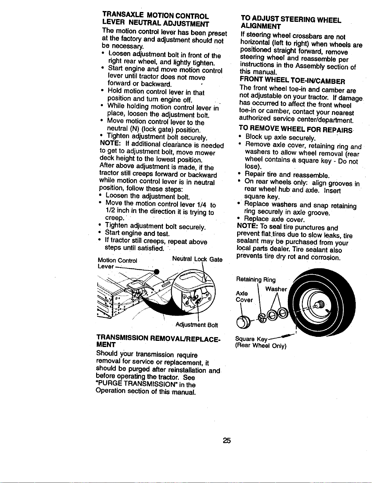
TRANSAXLE MOTION CONTROL
LEVER NEUTRAL ADJUSTMENT
The motion control lever has been preset
at the factory and adjustment should not
be necessary.
• Loosen adjustment bolt in front of the
right rear wheel, and lightly tighten.
• Start engine and move motion control
lever until tractor does not move
forward or backward.
• Hold motion control lever in that
position and turn engine off..
• While holding motion control lever in
place, loosen the adjustment bolt.
• Move motion control lever to the
neutral (N) (lock gate) position.
• Tighten adjustment bolt securely,
NOTE: If additional clearance is needed
to get to adjustment bolt, move mower
deck height to the lowest position.
After above adjustment is made, if the
tractor still creeps forward or backward
while motion control lever is in neutral
position, follow these steps:
• Loosen the adjustment bolt.
• Move the motion control lever 1/4 to
1/2 inch in the d rect on it s trying to
creep.
• Tighten adjustment bolt securely.
• Start engine and test.
• If tractor still creeps; repeat above
steps until satisfied,
Motion Control Neutral Lock Gate
TO ADJUST STEERING WHEEL
ALIGNMENT
If steering wheel crossbars are not
horizontal (left to right) when whee s are
positioned straight forward, remove
steering wheel and reassemble per
instructions in the Assembly section of
this manual.
FRONT WHEEL TOE-IN/CAMBER
The front wheel toe-in and camber are
not adjustable on your tractor, if damage
has occurred to affect the front wheel
toe-in or camber, contact your nearest
authorized service centerldepartment.
TO REMOVE WHEEL FOR REPAIRS
• Block up axle securely.
• Remove axle cover, retaining ring and
washers to allow wheel removal (rear
wheel contains a square key - Do not
lose).
• Repair tire and reassemble.
• On rear wheels only: align grooves in
rear wheel hub and axle. Insert
square key.
• • Replace washers and snap retaining
ring securely in axle groove.
• Replace axle cover.
NOTE: To seal tire punctures and
prevent flat.tiv'es due to sl0w leaks, tire
sealant may be PUrchased from your
local parts dealer. Tire sealant also
prevents tire dry rot and corrosion.
Retaining Ring
Axle
Cover
Adjustment Bolt
TRANSMISSION REMOVAL/REPLACE-
MENT
Should your transmission require
removal for service or replacement, it
should be purged after reinstallation and
before operating the tractor. See
=PURGE TRANSMISSION" in the
Operation section of this manual.
I
Square Key
(Reef Wheel Only)
25
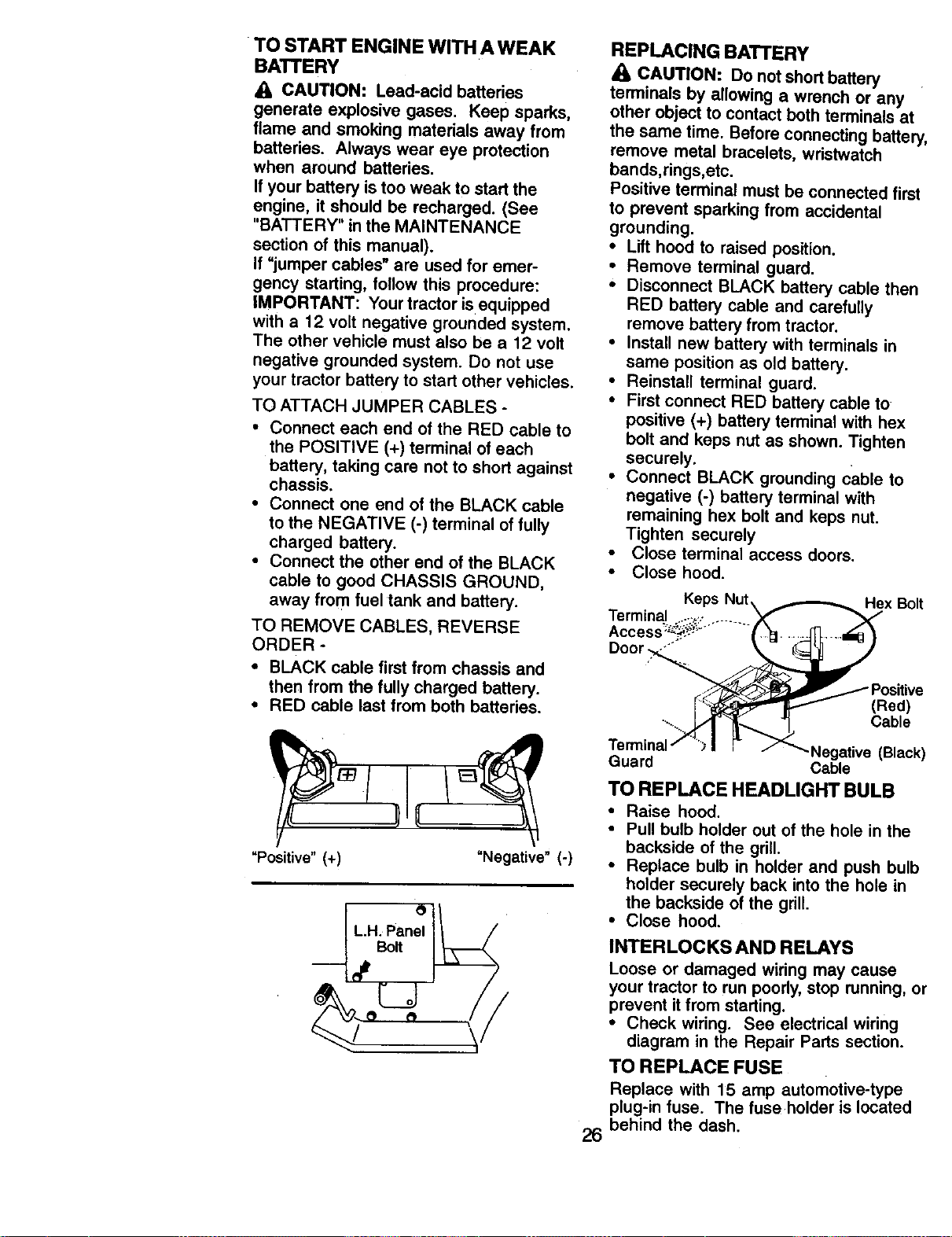
TO START ENGINE WITH A WEAK
BATTERY
CAUTION: Lead-acid batteries
generate explosive gases. Keep sparks,
flame and smoking materials away from
batteries. Always wear eye protection
when around batteries.
If your battery is too weak to start the
engine, it should be recharged. (See
"BATTERY" in the MAINTENANCE
section of this manual).
If "jumper cables" are used for emer-
gency starting, follow this procedure:
IMPORTANT: Your tractor is equipped
with a 12 volt negative grounded system.
The other vehicle must also be a 12 volt
negative grounded system. Do not use
your tractor battery to start other vehicles.
TO ATTACH JUMPER CABLES -
• Connect each end of the RED cable to
the POSITIVE (+) terminal of each
battery, taking care not to short against
chassis.
• Connect one end of the BLACK cable
to the NEGATIVE (-) terminal of fully
charged battery.
• Connect the other end of the BLACK
cable to good CHASSIS GROUND,
away from fuel tank and battery.
TO REMOVE CABLES, REVERSE
ORDER -
• BLACK cable first from chassis and
then from the fully charged battery.
• RED cable last from both batteries.
q
Bolt
!
"Positive" (+)
"Negative" (-)
REPLACING BATTERY
• 1,CAUTION: Do not short battery
terminals by allowing a wrench or any
other object to contact both terminals at
the same time. Before connecting battery,
remove metal bracelets, wristwatch
bands,rings,etc.
Positive terminal must be connected first
to prevent sparking from accidental
grounding.
• Lift hood to raised position.
• Remove terminal guard.
• Disconnect BLACK battery cable then
RED battery cable and carefully
remove battery from tractor.
• Install new battery with terminals in
same position as old battery.
• Reinstall terminal guard.
• First connect RED battery cable to
positive (+) battery terminal with hex
bolt and keps nut as shown. Tighten
securely.
• Connect BLACK grounding cable to
negative (-) battery terminal with
remaining hex bolt and keps nut.
Tighten securely
• Close terminal access doors.
• Close hood.
Hex Bolt
26
(Red)
Cable
-Negative (Black)
Guard Cable
TO REPLACE HEADLIGHT BULB
• Raise hood.
• Pull bulb holder out of the hole in the
backside of the grill.
• Replace bulb in holder and push bulb
holder securely back into the hole in
the backside of the grill.
• Close hood.
INTERLOCKS AND RELAYS
Loose or damaged wiring may cause
your tractor to run poorly, stop running, or
prevent it from starting.
• Check wiring. See electrical wiring
diagram in the Repair Parts section.
TO REPLACE FUSE
Replace with 15 amp automotive-type
plug-in fuse. The fuse holder is located
behind the dash.
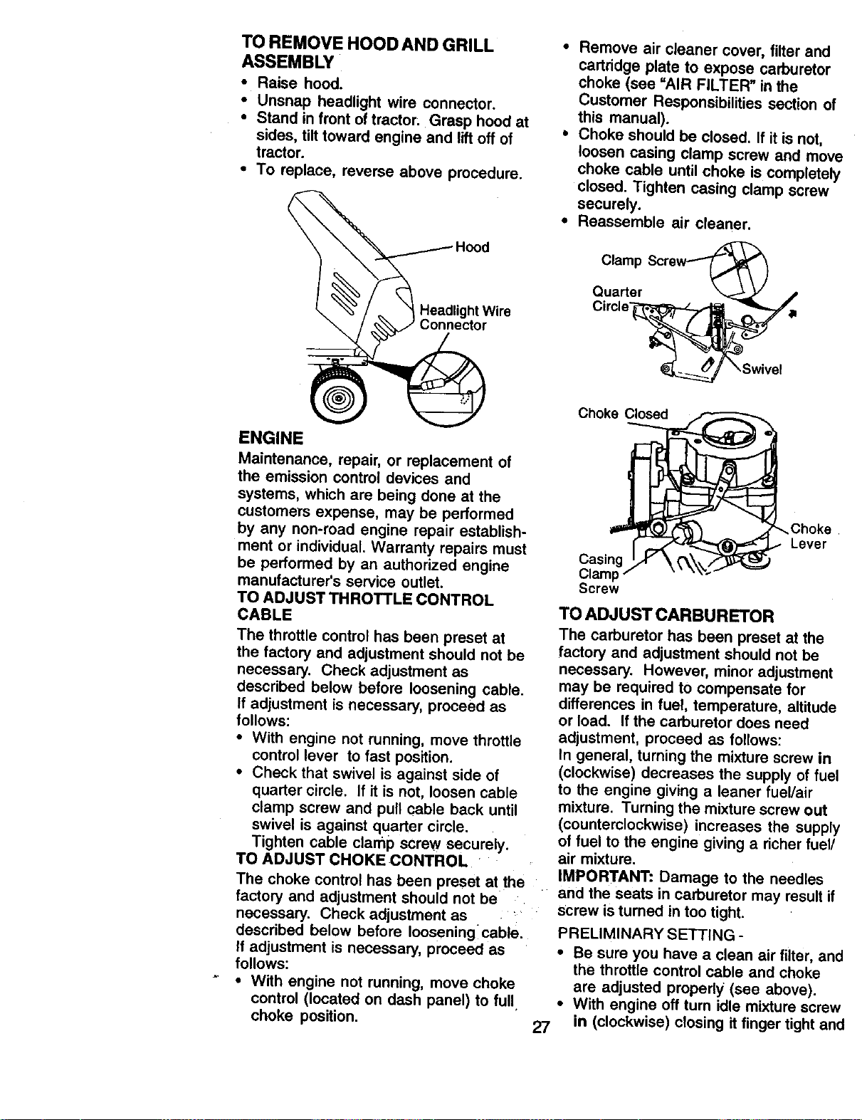
TO REMOVE HOOD AND GRILL
ASSEMBLY
• Raise hood.
• Unsnap headlight wire connector.
• Stand in front of tractor: Grasp hood at
sides, tilt toward engine and liftoff of
tractor.
• To replace, reverse above procedure.
• Remove air cleaner cover, filter and
cartddge plate to expose carburetor
choke (see "AIR FILTER" in the
Customer Responsibilities section of
this manual).
• Choke should be closed. If it is not,
loosen casing clamp screw and move
choke cable until choke is completely
closed. Tighten casing clamp screw
securely.
• Reassemble air cleaner.
Headlight Wire
Connector
Clamp
Quarter
ENGINE
Maintenance, repair, or replacement of
the emission control devices and
systems, which are being done at the
customers expense, may be performed
by any non-road engine repair establish-
ment or individual. Warranty repairs must
be performed by an authorized engine
manufacturer's service outlet.
TO ADJUST THROTTLE CONTROL
CABLE
The throttle control has been preset at
the factory and adjustment should not be
necessary. Check adjustment as
described below before loosening cable.
If adjustment is necessary, proceed as
follows:
• With engine not running, move throttle
control lever to fast position.
• Check that swivel is against side of
quarter circle. If it is not, loosen cable
clamp screw and pull cable back until
swivel is against quarter circle.
Tighten cable clamp screw securely.
TO ADJUST CHOKE CONTROL
The choke control has been preset at the
factory and adjustment should not be
necessary. Check adjustment as
described below before Iooseningcable.
If adjustment is necessary, proceed as
follows:
• With engine not running, move choke
control (located on dash panel) to full
choke position,
27
Choke Closed
_Choke
Lever
Casing
Clam_
Screw
TO ADJUST CARBURETOR
The carburetor has been preset at the
factory and adjustment should not be
necessary. However, minor adjustment
may be required to compensate for
differences in fuel, temperature, altitude
or load. If the carburetor does need
adjustment, proceed as follows:
In general, turning the mixture screw in
(clockwise) decreases the supply of fuel
to the engine giving a leaner fuel/air
mixture. Turning the mixture screw out
(counterclockwise) increases the supply
of fuel to the engine giving a richer fuel/
air mixture.
IMPORTANT: Damage to the needles
and the seats in carburetor may result if
screw is turned in too tight.
PRELIMINARY SETTING -
• Be sure you have a clean air filter, and
the throttle control cable and choke
are adjusted propedy (sea above).
• With engine off tum idle mixture screw
in (clockwise) closing it finger tight anc
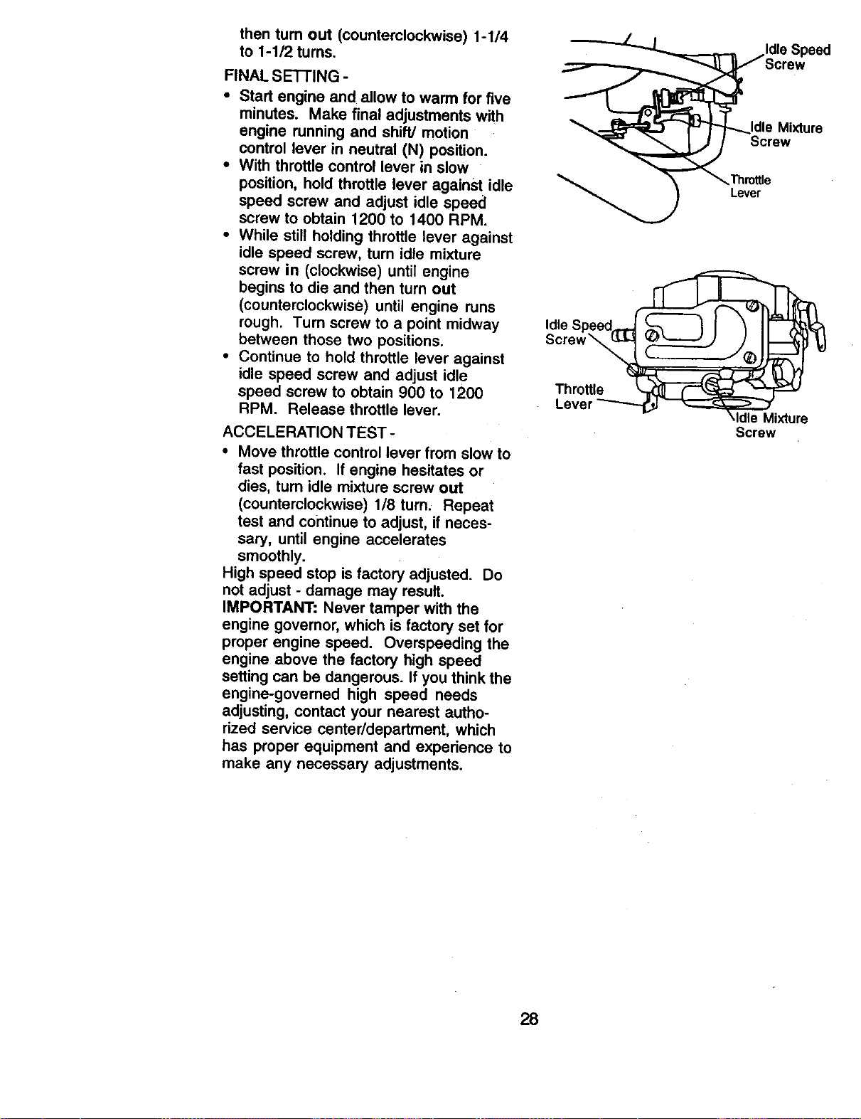
thentum out (counterclockwise)1-1/4
to 1-1/2tums.
FINALSE'I-rlNG-
• Start engine and allow to warm for five
minutes. Make final adjustments with
engine running and shift/motion
control lever in neutral (N) position.
• With throttle control lever in slow
position, hold throttle lever against idle
speed screw and adjust idle speed
screw to obtain 1200 to 1400 RPM.
• While still holding throttle lever against
idle speed screw, turn idle mixture
screw in (clockwise) until engine
begins to die and then turn out
(counterclockwise) until engine runs
rough. Turn screw to a point midway
between those two positions.
• Continue to hold throttle lever against
idle speed screw and adjust idle
speed screw to obtain 900 to 1200
RPM. Release throttle lever.
ACCELERATION TEST -
• Move throttle control lever from slow to
fast position. If engine hesitates or
dies, turn idle mixture screw out
(counterclockwise) 1/8 turn, Repeat
test and continue to adjust, if neces-
sary, until engine accelerates
smoothly.
High speed stop is factory adjusted. Do
not adjust - damage may result.
IMPORTANT: Never tamper with the
engine governor, which is factory set for
proper engine speed. Overspeeding the
engine above the factory high speed
setting can be dangerous. If you think the
engine-govemed high speed needs
adjusting, contact your nearest autho-
rized service center/department, which
has proper equipment and experience to
make any necessary adjustments.
die Mixture
Screw
Lever
Idle Speed_
Lever _ _r..---=_---,f
\Idle Mixture
Screw
28
Immediately prepare your tractor for
storage at the end of the season or ifthe
tractor will not be used for 30 days or
more.
_. CAUTION: Never store the tractor
with gasoline in the tank inside a
building where fumes may reach an
open flame or spark. Allow the engine to
cool before storing in any enclosure.
TRACTOR
Remove mower from tractor for winter
storage. When mower is to be stored for
a period of time, clean it thoroughly,
remove all dirt, grease, leaves, etc. Store
in a clean, dry area.
• Clean entire tractor (See "CLEANING"
in the Maintenance section of this
manual).
• Inspect and replace belts, if necessary
(See belt replacement instructions in
the Service and Adjustments section of
this manual).
• Lubricate as shown in the Mainte-
nance section of this manual.
• Be sure that all nuts, bolts and screws
are securely fastened. Inspect moving
parts for damage, breakage and wear.
Replace if necessary.
• Touch up all rusted or chipped paint
surfaces; sand lightly before painting.
BAI-rERY
• Fullycharge the battery for Storage.
• After a period of time in storage,
battery may require recharging.
• To help prevent corrosion and power
leakage during long periods of
storage, battery cables should be
disconnected and battery cleaned
thoroughly (see ='1"OCLEAN BATTERY
AND TERMINALS" in the Maintenance
section of this manual).
• After cleaning, leave cables discon-
nscted and place cables where they
cannot come in contact with battery
terminals.
• If battery is removed from tractor for
storage, do not store battery directly on
concrete or damp surfaces.
ENGINE
FUEL SYSTEM
IMPORTANT: It isimportant toprevent
gum deposits from forming in essential
fuel system parts such as carburetor, fuel
filter, fuel hose, or tank duringstorage.
Also, experience indicates that alcohol
blended fuels called gasohol or using
ethanol or methanol) can attract moisture
which leads to separation and formation
of acids during storage. Acidic gas can
damage the fuel system of an engine
while in storage.
• Drai_nthe fuel tank.
• Start the engine and let it run until the
fuel lines and carburetor are empty.
• Never use engine or carburetor
cleaner products in the fuel tank or
permanent damage may occur.
• Use fresh fuel next season.
NOTE: Fuel stabilizer is an acceptable
alternative in minimizing the formation of
fuel gum deposits during storage. Add
stabilizer to gasoline in fuel tank or
storage container. Always follow the mix
ratio found on stabilizer container. Run
engine at least 10 minutes after adding
stabilizer to allow the stabilizer to reach
the carburetor. Do not drain the gas tank
and carburetor if using fuel stabilizer.
ENGINEOIL
Drain oil (with engine warm) and replace
with clean engine oil. (See =ENGINE" in
the Maintenance section of this manual).
CYLINDER(S)
• Remove spark plug(s),
• Pour one ounce of oil through spark
plug hole(s) into cylinder(s).
• Turn ignition key to =START" position
for a few seconds to distributeoil.
• Replace with new spark plug(s).
OTHER
• Do not store gasoline from one season
to another.
* Replace your gasoline can if your can
starts to rust. Rust and/or dirt in your
gasoline will cause problems.
• If possible, store your tractor indoors
and cover it to give protection from
dust and dirt.
• Cover your tractor with a suitable
protective cover that does not retain
moisture. Do not use plastic. Plastic
cannot breathe which allows conden-
sation to form and will cause your
tractor to rust.
IMPORTANT: Never cover tractor while
engine and exhaust areas are still
warm,
29
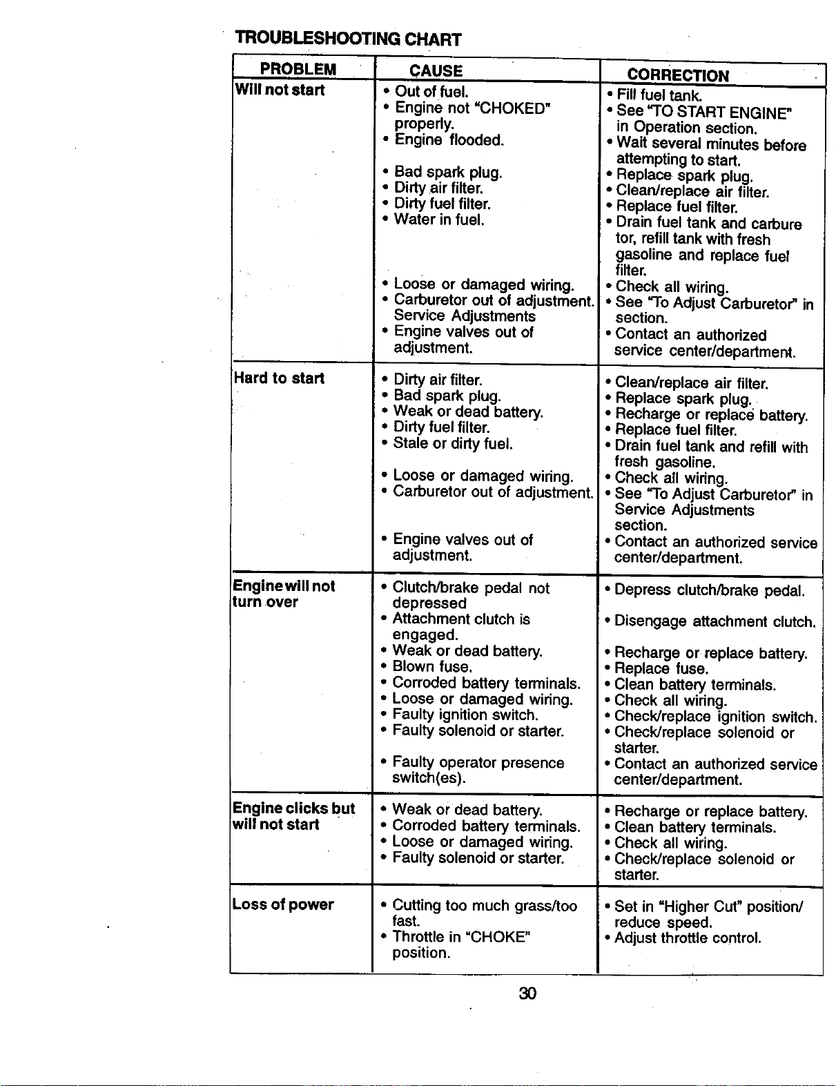
TROUBLESHOOTINGCHART
PROBLEM CAUSE
Will not start • Out of fuel.
Hard to start
Engine will not
turn over
Engine clicks but
will not start
Loss of power
• Engine not "CHOKED"
properly.
• Engine flooded.
• Bad spark plug.
• Dirty air filter.
• Dirty fuel filter.
• Water in fuel.
• Loose or damaged wiring.
• Carburetor out of adjustment.
Service Adjustments
• Engine valves out of
adjustment.
• Dirty air filter.
• Bad spark plug.
• Weak or dead battery.
• Dirty fuel filter.
• Stale or dirty fuel.
• Loose or damaged wiring.
• Carburetor out of adjustment.
• Engine valves out of
adjustment.
• Clutch/brake pedal not
depressed
• Attachment clutch is
engaged.
• Weak or dead battery.
• Blown fuse.
• Corroded battery terminals.
• Loose or damaged widng.
• Faulty ignition switch.
• Faulty solenoid or starter.
• Faulty operator presence
switch(es).
• Weak or dead battery.
• Corroded battery terminals.
• Loose or damaged wiring.
• Faulty solenoid or starter.
• Cutting too much grass/too
fast.
• Throttle in "CHOKE"
position.
CORRECTION
• Fill fuel tank.
• See "TO START ENGINE"
in Operation section.
• Wait several minutes before
attempting to start,
• Replace spark plug.
• Clean/replace air filter.
• Replace fuel filter.
• Drain fuel tank and carbure
tor, refill tank with fresh
gasoline and replace fuel
filter.
• Check all wiring.
i, See "To Adjust Carburetor" in
section.
• Contact an authorized
service center/department.
• Clean/replace air filter.
• Replace spark plug.
• Recharge or replace battery.
• Replace fuel filter.
• Drain fuel tank and refill with
fresh gasoline.
• Check all wiring.
• See "To Adjust Carburetor" in
Service Adjustments
section.
• Contact an authorized service
center/department.
• Depress clutch/brake pedal.
• Disengage attachment clutch.
• Recharge or replace battery.
• Replace fuse.
• Clean battery terminals.
• Check all widng.
• Check/replace ignition switch.
• Check/replace solenoid or
starter.
• Contact an authorized service
center/department.
• Recharge or replace battery.
• Clean battery terminals.
• Check all wiring.
• Check/replace solenoid or
starter.
• Set in =Higher Cut" position/
reduce speed.
• Adjust throttle control,
30
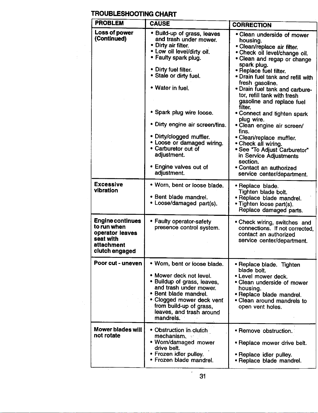
TROUBLESHOOTINq
PROBLEM
Loss of power
(Continued)
Excessive
vibration
;CHART
CAUSE
•Build-upofgr_s, leaves
andtmshundermowe_
Enginecontinues
to run when
operator leaves
seat with
attachment
clutch engaged
Poor cut - uneven
Mower blades will
not rotate
• Dirty air filter.
• Low oil level/dirty oil
• Faulty spark plug.
• Dirty fuel filter.
• Stale or dirty fuel.
• Water in fuel,
• Spark plug wire loose.
• Dirty engine air screen/fins.
• Dirty/clogged muffler.
• Loose or damaged wiring.
• Carburetor out of
adjustment.
• Engine valves out of
adjustment.
• Worn, bent or loose blade.
• Bent blade mandrel.
• Loose/damaged part(s).
• Faulty operator-safety
presence control system.
• Worn, bent or loose blade.
• Mower deck not level.
• Buildup of grass, leaves,
and trash under mower.
• Bent blade mandrel.
• Clogged mower deck vent
from build-up of grass,
leaves, and trash around
mandrelS.
i
• Obstruction in clutch
mechanism. _
• Worn/damaged mower
drive belt.
• Frozen idler pulley.
• Frozen blade mandrel.
CORRECTION
i
• Clean underside of mower
housing.
• Clean/replace air filter.
• Check oil level/change oil.
• Clean and regap or chang(
spark plug.
• Replace fuel filter.
• Drain fuel tank and refill wit
fresh gasoline.
• Drain fuel tank and carbure
tor, refill tank with fresh
gasoline and replace fuel
filter.
• Connect and tighten spark
plug wire.
• Clean engine air screen/
fins.
• Clead/replace muffler.
• Check all wiring.
• See "To Adjust Carburetor"
in Service Adjustments
section.
• Contact an authorized
service center/department.
• Replace blade.
Tighten blade bolt.
• Replace blade mandrel.
• Tighten loose part(s).
Replace damaged parts.
• Check wiring, switches an(
connections. If not correcte,
contact an authorized
service centeddepadment.
• Replace blade. Tighten
blade bolt.
• Level mower deck.
• Clean underside of mower
housing.
• Replace blade mandrel.
• Clean around mandrels to
open vent holes.
• Remove obstruction.
• Replace mower drive belt.
• Replace idler pulley.
• Replace blade mandrel.
31
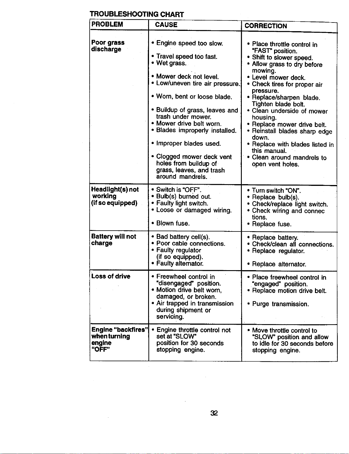
TROUBLESHOOTINGCHART
PROBLEM CORRECTION
Poor grass
discharge
Headlight(s) not
working
(if so equipped)
Battery will not
charge
Loss of drive
Engine "backfires"
whenturning
engine
"OFF"
CAUSE
• Engine speed too slow.
• Travel speed too fast.
• Wet grass.
I, Mower deck not level.
I • Low/uneven tire air pressure.
• Worn, bent or loose blade.
• Buildup of grass, leaves and
trash under mower.
• Mower drive belt worn.
• Blades improperly installed.
• improper blades used.
• Clogged mower deck vent
holes from buildup of
grass, leaves, and trash
around mandrels.
• Switch is "OFF".
• Bulb(s) burned out.
• Faulty light switch.
• Loose or damaged wiring.
Io Blown fuse.
• Bad battery cell(s).
• Poor cable connections.
• Faulty regulator
(if so equipped).
• Faulty alternator.
• Freewheel control in
=disengaged" position.
• Motion drive belt worn,
damaged, or broken.
• Air trapped in transmission
during shipment or
servicing.
• Engine throttle control not
set at "SLOW"
position for 30 seconds
stopping engine.
• Place throttle control in
=FAST" position.
• Shift to slower speed.
• Allow grass to dry before
mowing.
• Level mower deck.
• Check tires for proper air
pressure.
• Rep!ace/sharpen blade.
Tighten blade bolt.
• Clean underside of mower
housing.
• Replace mower drive belt.
• Reinstall blades sharp edge
down.
• Replace with blades listed in
this manual.
• Clean around mandrels to
open vent holes.
• Turn switch "ON".
• Replace bulb(s).
• Check/replace light switch.
• Check wiring and connec
tions.
• Replace fuse.
• Replace battery.
• Check]clean all connections.
• Replace regulator.
• Replace alternator.
• Place freewheel control in
"engaged" position.
• Replace motion drive belt.
• Purge transmission.
• Move throttle controlto
"SLOW" position and allow
to idle for 30 seconds before
stopping engine.
32
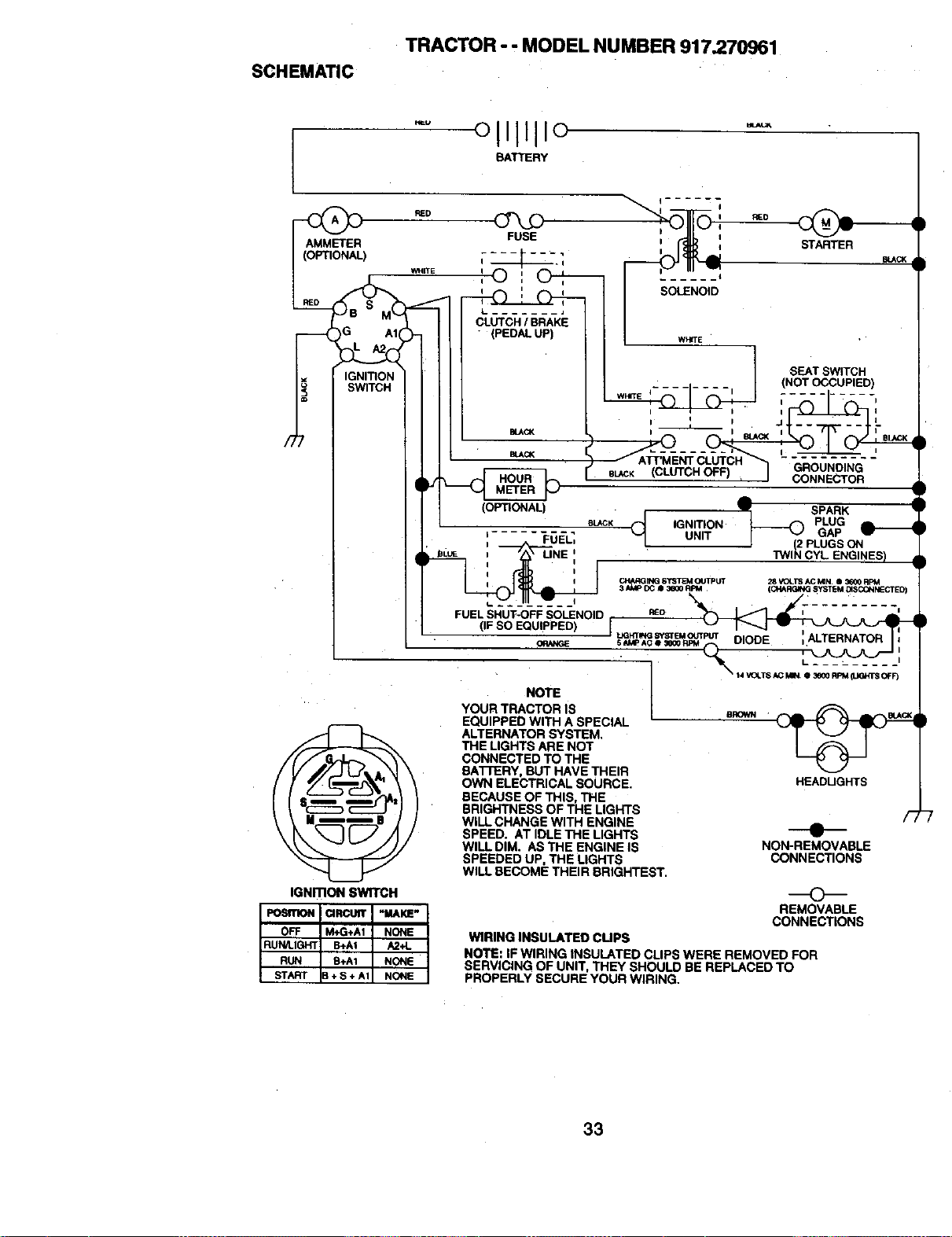
SCHEMATIC
TRACTOR -. MODEL NUMBER 917.270961
AMMETER FUSE
(OPTIONAL)
WHITE
IGNITION
SWITCH
IGNmON SWITCH
STARTER
BLACK
SEAT SWITCH
I
{CLUTCH OFF) GROUNDING
CONNECTOR
SPARK
PLUG
IGNITION
_ - GAP
UNIT
J (2 PLUGS ON
TWIN CYL ENGINES)
• t4 rOt.T8 AC MIN_• _ f_M _J(3_r's OFF_
NOTE
YOUR TRACTOR IS
EQUIPPED WITH A SPECIAL
ALTERNATOR SYSTEM,
THE LIGHTS ARE NOT
CONNECTED TO THE
BATrERY, BUT HAVE THEIR
OWN ELECTRICAL SOURCE.
BECAUSE OF THIS, THE
BRIGHTNESS OF THE LIGHTS
WILL CHANGE WITH ENGINE
SPEED. AT IDLE THE LIGHTS
WILL DIM. AS THE ENGINE IS
SPEEDED UP, THE LIGHTS
WILL BECOME THEIR BRIGHTEST.
_EADUGHTS
F,
O
NON-REMOVABLE
CONNECTIONS
REMOVABLE
CONNECTIONS
WIRING INSULATED CUPS
NOTE: IF WIRING INSULATED CLIPS WERE REMOVED FOR
SERVICING OF UNIT, THEY SHOULD BE REPLACED TO
PROPERLY SECURE YOUR WIRING.
)
33
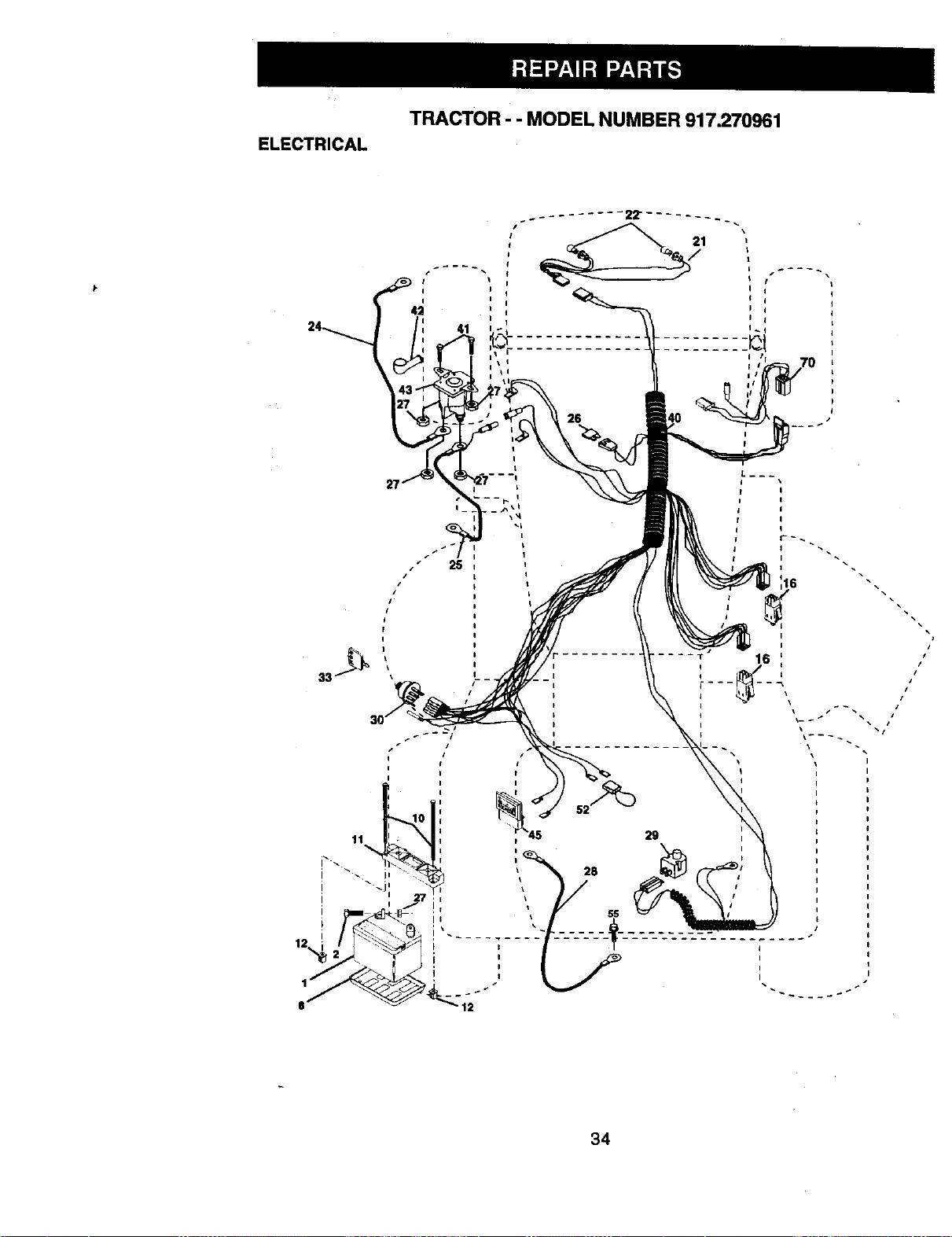
TRACTOR - - MODEL NUMBER 917.270961
ELECTRICAL
I
25
I
I
I
I
i I
34
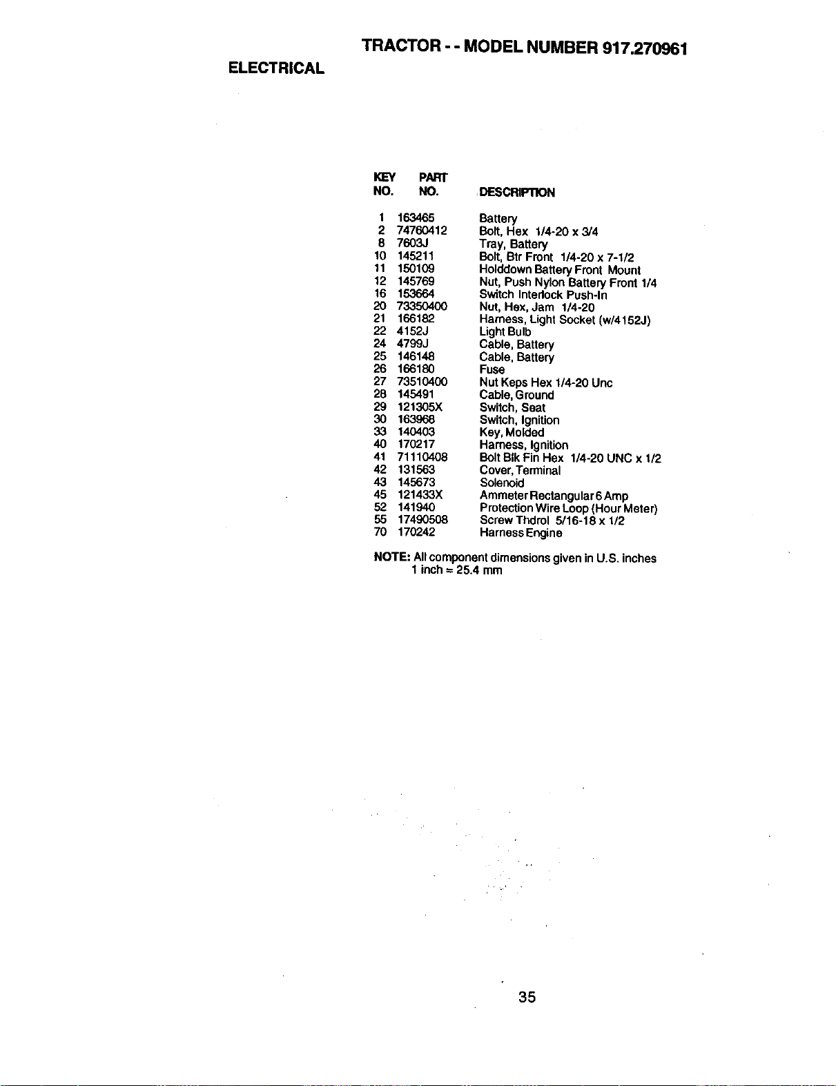
ELECTRICAL
TRACTOR - - MODEL NUMBER 917.270961
KEY PARr
NO. NO. DESCRIFnON
1 163465 Battery
2 74760412 Bolt,Hex 1/4-20x3/4
8 7603J Tray, Battery
10 145211 Bolt,Btr Front 1/4-20 x 7-I/2
11 150109 HolddownBatteryFmnt Mount
12 145769 Nut, Push Nylon Battery Front 1/4
16 153664 Switch InterlockPush-In
20 73350400 Nut, Hex, Jam 1/4-20
21 166182 Harness, Light Socket (w/4152J)
22 4152J LightBulb
24 4799J Cable, Battery
25 146148 Cable, Battery
26 166180 Fuse
27 73510400 Nut Keps Hex 1/4-20 Unc
28 145491 Cable,Ground
29 121305X Switch, Seat
30 163968 Switch, Ignition
33 140403 Key, Molded
40 170217 Harness, Ignition
41 71110408 BoltBIkFinHex 1/4-20UNCxl/2
42 131563 Cover,Terminal
43 145673 Solenoid
45 121433X AmmeterRectangular6 Amp
52 141940 ProtectionWire Loop(Hour Meter)
55 17490508 ScrewThdrol 5/16-18x1/2
70 170242 HarnessEngine
NOTE: Allcomponentdimensionsgiven in U.S. inches
1inch= 25.4 mm
35
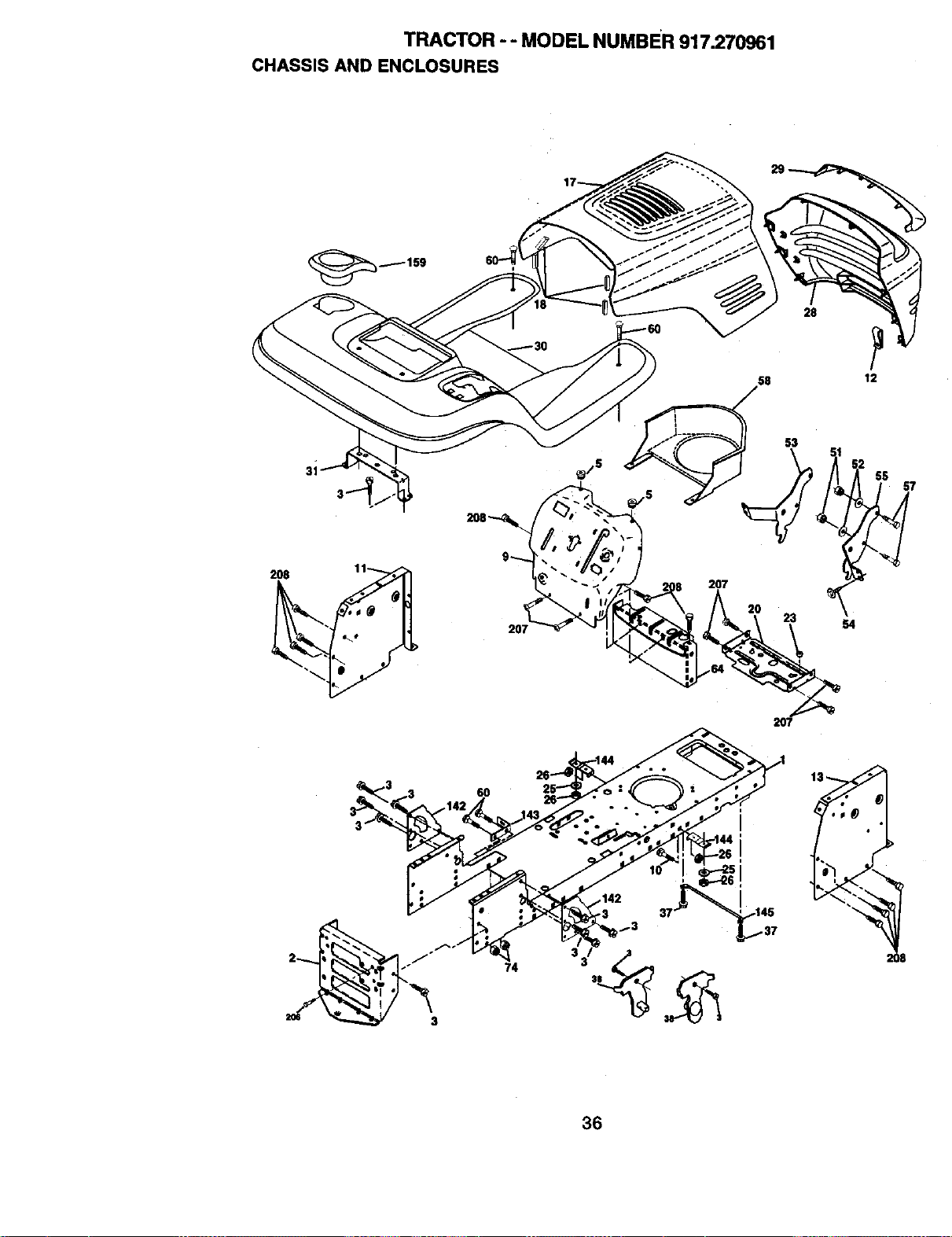
TRACTOR - - MODEL NUMBER 917.270961
CHASSIS AND ENCLOSURES
58 12
31
207
2O7
6O
74
36
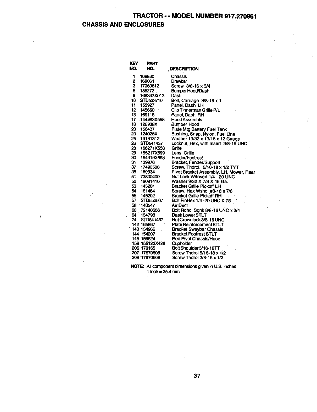
TRACTOR- - MODEL NUMBER 917.270961
CHASSISAND ENCLOSURES
I<L=Y PART
NO, NO. DESCI_IPTION
1 169830
2 169061
3 17060612
5 155272
9 168337X013
t0 STD533710
11 155927
12 145660
13 169118
17 144983X558
18 126938X
20 156437
23 124028)(
25 19131312
26 STD541437
28 166271X558
29 155217X599
30 164919X558
31 139976
37 17490508
38 169834
51 73800400
52 19091416
53 145201
54 161464
55 145202
57 STD552507
58 140547
60 72140606
64 154796
74 STD541437
142 165867
143 154966
144 154207
145 156524
159 155123X428
206 170165
207 17670508
208 17670608
Chassis
Drawbar
Screw. 3/8-16 x 3/4
BumperH_x_l/Dash
Dash
Bolt,Carriage 3/8-16 x 1
Panel, Dash, LH
Clip TinnermanGrille P/L
Panel, Dash, RH
HoodAssembly
Bumber Hood
Plate Mtg Battery FuelTank
Bushing,Snap, Nylon, Fuel Line
Washer 13/32 x 13/16 x 12 Gauge
Looknut,Hex, with Insert 3/8-16 UNC
Gdlle
Lens, Grille
Fender/Footrest
Bracket, FenderlSupport
Screw, Thdrol. 5/16.18 x 112TYT
Pivot Bracket Assembly, LH, Mower, Rear
Nut LockW/Insert 1/4 - 20 UNC
Washer 9/32 X 7/8 X 16 Ga.
Bracket Gdlle PickoffLH
Screw, Hex Wshd #8-18 x 718
Bracket Grille PickoffRH
BoltFinHex 1/4 -20 UNC X.7S
Air Duct
BoltRdhd Sqnk 3/8-16 UNC x 3/4
DashLowerSTLT
NutCrownlock3/8-16 UNC
Plate ReinforcementSTLT
Bracket Swaybar Chassis
Bracket Footrest STLT
Rod PivotChassis/Hood
Cuph_der
BoltShoulder5/16.18TT
ScrewThdrol 5/16-18 x 1/2
ScrewThdrol 3/8-16 x 1/2
NOTE: Allcomponentdimensionsgivenin U.S. inches
1ir_ch= 25.4 mm
37
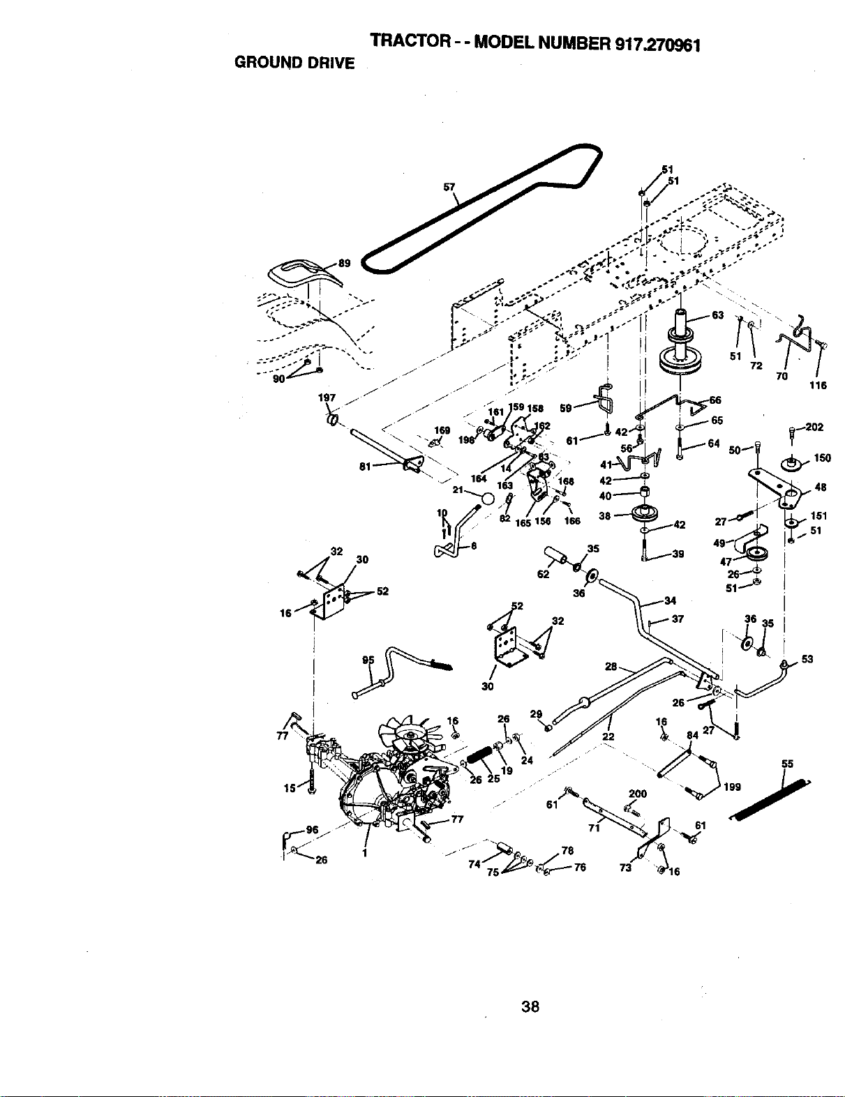
TRACTOR - - MODEL NUMBER 917.270961
GROUND DRIVE
/
J
/ _ "161 !59 158
169
32
52
16
3S
36
38
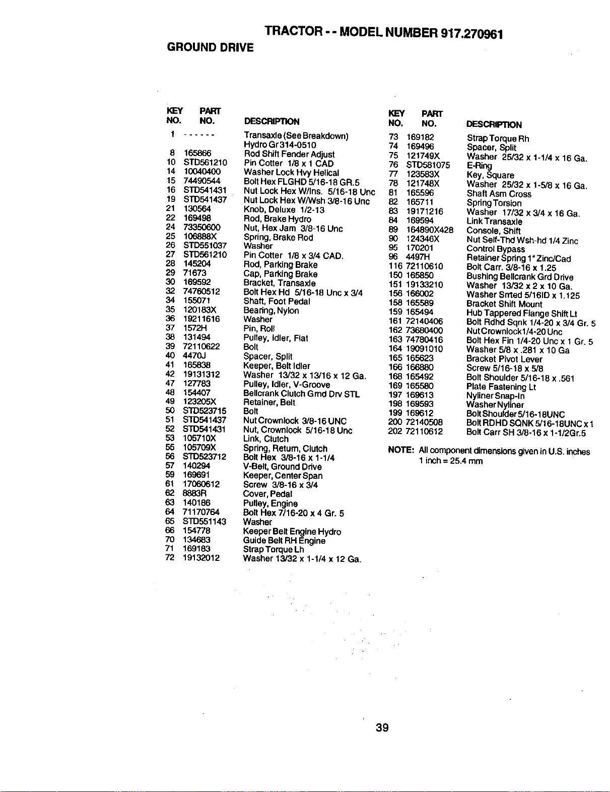
TRACTOR -- MODEL NUMBER 917.270961
GROUND DRIVE
KEY PART _ PART
NO. NO. DESCRIPTION NO. NO.
1 ...... Transaxle (See Breakdown) 73 169182
HydroGr314-0510 74 169496
8 165866 Rod ShiftFenderAdjust 75 121749X
10 STD561210 PinCotter I/8xlCAD 76 STD58t075
14 10040400 WasherLockHwHetieal 77 123583X
15 74490544 BoltHexFLGHD5/16-18GR.5 78 121748X
16 STD541431 Nut Lock Hex W/Ins. 5/16-18 Unc 81 165596
19 STD541437 NutLockHexW/Wsh3/8-16Unc 82 165711
21 130564 Knob, Deluxe 1/2-13 83 19171216
22 169498 Rod, Brake Hydro 84 169594
24 7335(To00 Nut,Hex Jam 3/8-16 Unc 89 164890X428
25 106888X Spdng, BrakeRod 90 124346X
26 STD551037 Washer 95 170201
27 S1"D561210 PinCotter I/8x3/4CAD. 96 4497H
28 145204 Rod, ParkingBrake 116 72110610
29 71673 Cap, Parking Brake 150 165850
30 169592 Bracket, Transaxle 151 19133210
32 74760512 BoltHexHd 5/16-18Uncx3/4 156 166002
34 155071 Shaft, Foot Pedal 158 165589
35 120183X Bearing, Nylon 159 165494
36 19211616 Washer 161 72140406
37 1572H Pin,Roll 162 73680400
38 131494 Pulley, Idler, Flat 163 74780416
39 72110622 Bolt 164 19091010
40 4470J Spacer, Split 165 165623
41 165838 Keeper, Belt Idler 166 166880
42 19131312 Washer 13/32 x 13/16 x 12 Ga. 168 165492
47 127783 Pulley,Idler, V-Groove 169 165580
48 154407 BellcrankClutchGmdDrvSTL 197 169613
49 123205X Retainer, Belt 198 169593
50 STD523715 Bolt 199 169612
51 STD541437 NutCrownlock 3/8-16UNC 200 72140508
52 STD541431 Nut,Crowniock 5/16-16Unc 202 7211(3612
53 105710X Link,Clutch
55 105709X Spring,Return, Clutch
56 s'rD523712 Bolt Hex 3/8-16 x 1-1/4
57 140294 V-Belt, GroundDrive
59 166691 Keeper,Center Span
61 17060612 Screw 3/8-16 x 3/4
62 8883R Cover, Pedal
63 140186 Pulley,Engine
64 71170764 Bolt Hex 7/16-20 x 4 Gr. 5
65 STD551143 Washer
66 154778 Keepsr Belt EngineHydro
70 134683 GuideBelt RH Engine
71 169183 StrapTorque Lh
72 19132012 Washer 13/32 x 1-114 x 12 Ga.
DESCRIPTION
StrapTorque Rh
Spacer, Sp_it
Washer 25/32 x 1-1/4 x 16 Ga.
E-Ring
Key, Square
Washer 25/32 x 1-5/8 x 16 Ga.
Shaft Asm Cross
SpdngTorsion
Washer 17/32 x 3/4 x 16 Ga,
LinkTransaxle
Console, Shift
Nut Self-Thd Wsh-hd 1/4Zinc
ControlBypass
Retainer Spring1"Zinc/Cad
BoltCerr. 3/8-16 x 1.25
BushingBellcrankGrd Drive
Washer 13/32 x 2 x 10 Ga.
Washer Srrted 5/161Dx 1.125
Bracket Shift Mount
HubTappered FlangeShiftLt
BoltRdhd Sqnk 1/4-20 x 3/4 Gr. _=
NutCrownlockl/4-20 Unc
BoltHex Fin 1/4-20 Unc x 1 Gr, 5
Washer 518x .281 x 10 Ga
Bracket Pivot Lever
Screw 5/16-18 x 5/6
Bert Shoutder5/16-18 x ,561
Plate Fastening Lt
NylinerSnap-In
Washer Nytiner
BoltShoulder5/16-18UNC
BoltRDHD SQNK 5/16-18UNC x 1
BoltCart SH 3(8-16 x 1-1/2Gr.5
NOTE: Allcomponentdimensionsgivenin U.S. inches
1{r_ch= 25A mm
39
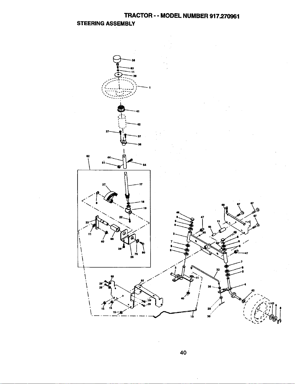
TRACTOR - - MODEL NUMBER 917.270961
STEERING ASSEMBLY
"" " """-'_ 1
.. 222-'--__22. -.
Ct:!
I
62 44
4O
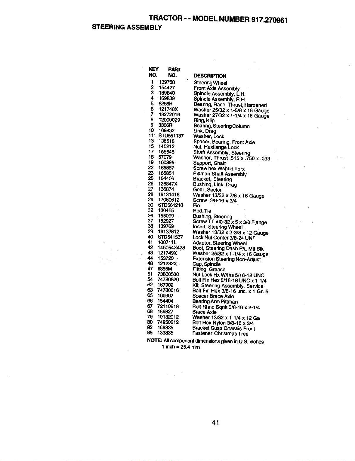
TRACTOR -- MODEL NUMBER 917.270961
STEERING ASSEMBLY
KEY PART
NO. NO.
1 139768
2 154427
3 169840
4 169839
5 6266H
6 121748X
7 19272016
8 12000029
9 3366R
10 169832
11 ST0551137
13 136518
15 145212
17 156546
18 57079
19 160395
22 165857
23 165851
25 154406
26 126847X
27 136874
28 19131416
29 17060612
3O STD561210
32 130465
36 155099
37 152927
38 139769
39 1913.3812
40 STD541537
41 100711L
42 145054X428
43 121749)(
44 153720+
46 121232X
47 6855M
51 738(X)500
54 74780520
62 167902
63 74780616
65 160367
66 154404
67 72110618
68 169827
79 19132012
80 74950612
82 169835
85 133835
DESCRIPTION
SteeringWheel
FrontAxle Assembly
Spindle Assembly, L.H.
SpindleAssembly, R.H.
Bearing, Race, Thrust, Hardened
Washer 25/32 x 1-5/8 x 16 Gauge
Washar 27/32 x 1-1/4 x 16 Gauge
Ring, Kllp
Bearing,SteeringColumn
Link, Drag
Washer, Lock
Spacer, Bearing, Front Axle
Nut, Hexflange Lock
Shaft Assembly, Steedng
Washer, Thrust .515 x .750 x .033
Support, Shaft
Screwhex Wshhd Torx
Pittman Shaft Assembly
Bracket, Steering
Bushing,Link, Drag
Gear, Sector
Washer 13/32 x 7/8 x 16 Gauge
Screw 3/8-16 x 3/4
Pin
Rod,Tie
Bushing,Steering
Screw TT #10-32 x5 X 3/8 Range
Insert, Steering Wheel
Washer 13/32 x 2-3/8 x 12 Gauge
Lock NutCenter 3/8-24 UNF
Adaptor,Steering Wheel
Boot, Steering Dash P/L Mtl BIk
Washer 25/32 x 1-1/4 x 16 Gauge
ExtensionSteering Non-Adjust
Cap, Spindle
Fitting,Grease
Nut Lock Hx W/Ins 5/16-18 UNC
BoltRn Hex 5/16-18 UNC x 1-1/4
Kit, Steering Assembly, Service
BoltFin Hex 3/8-16 uric. x 1 Gr. 5
Spacer Brace Axle
BearingArmPittman
Belt RhndSqnk 3/8-16 x 2-I14
Brace Axle
Washer 13/32 x 1-1/4 x 12 Ga
BoltHex Nylon 3/8-16 x 3/4
Bracket Susp Chassis Front
Fastener ChristmasTree
NOTE: Allcomponentdimensionsgivenin U.S. inctles
1 inch = 25.4 mm
41
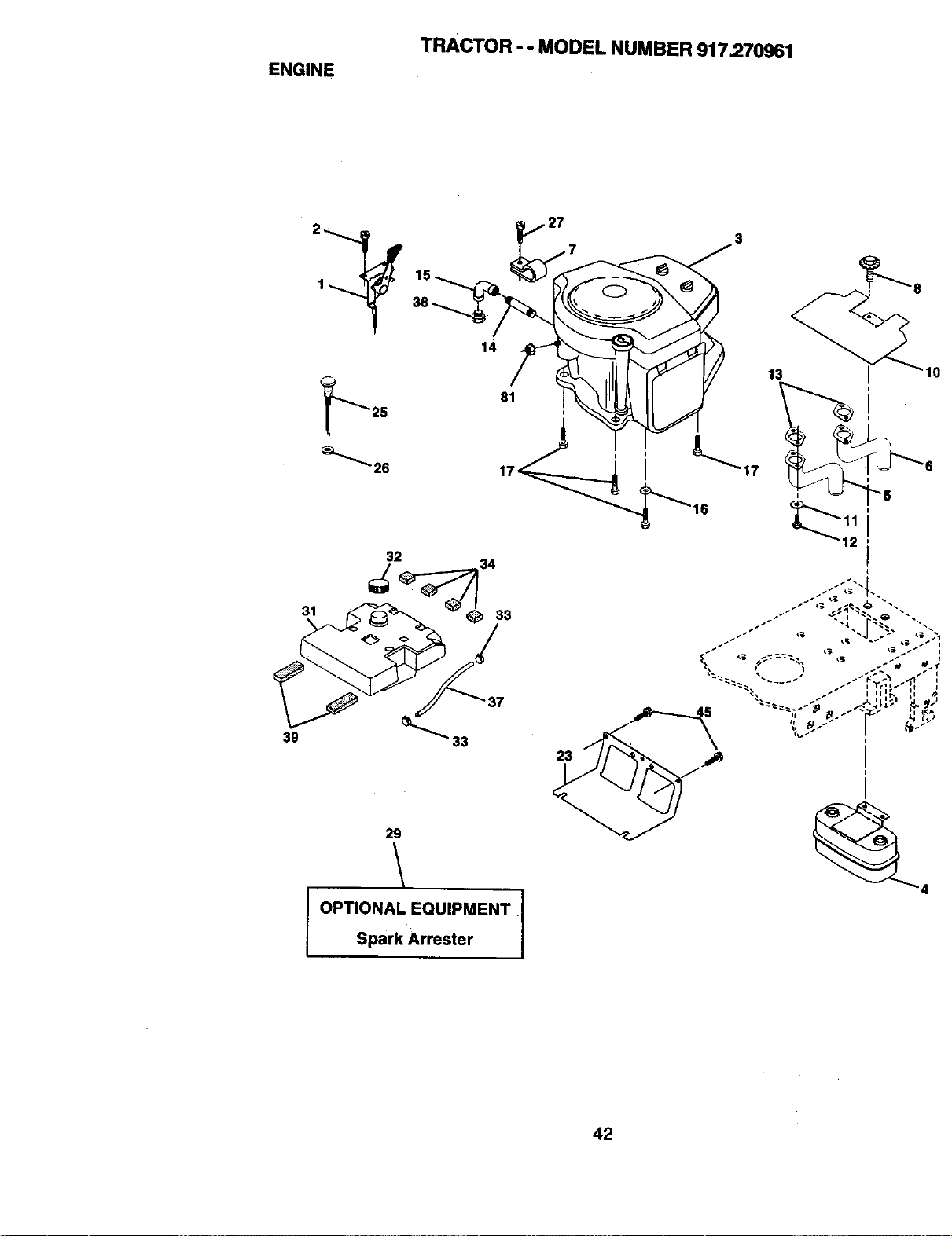
ENGINE
TRACTOR - - MODEL NUMBER 917.270961
32
31 33
39 33
29
I OPTIONAL EQUIPMENT
Spark Arrester
0
i
i
i
12I
42
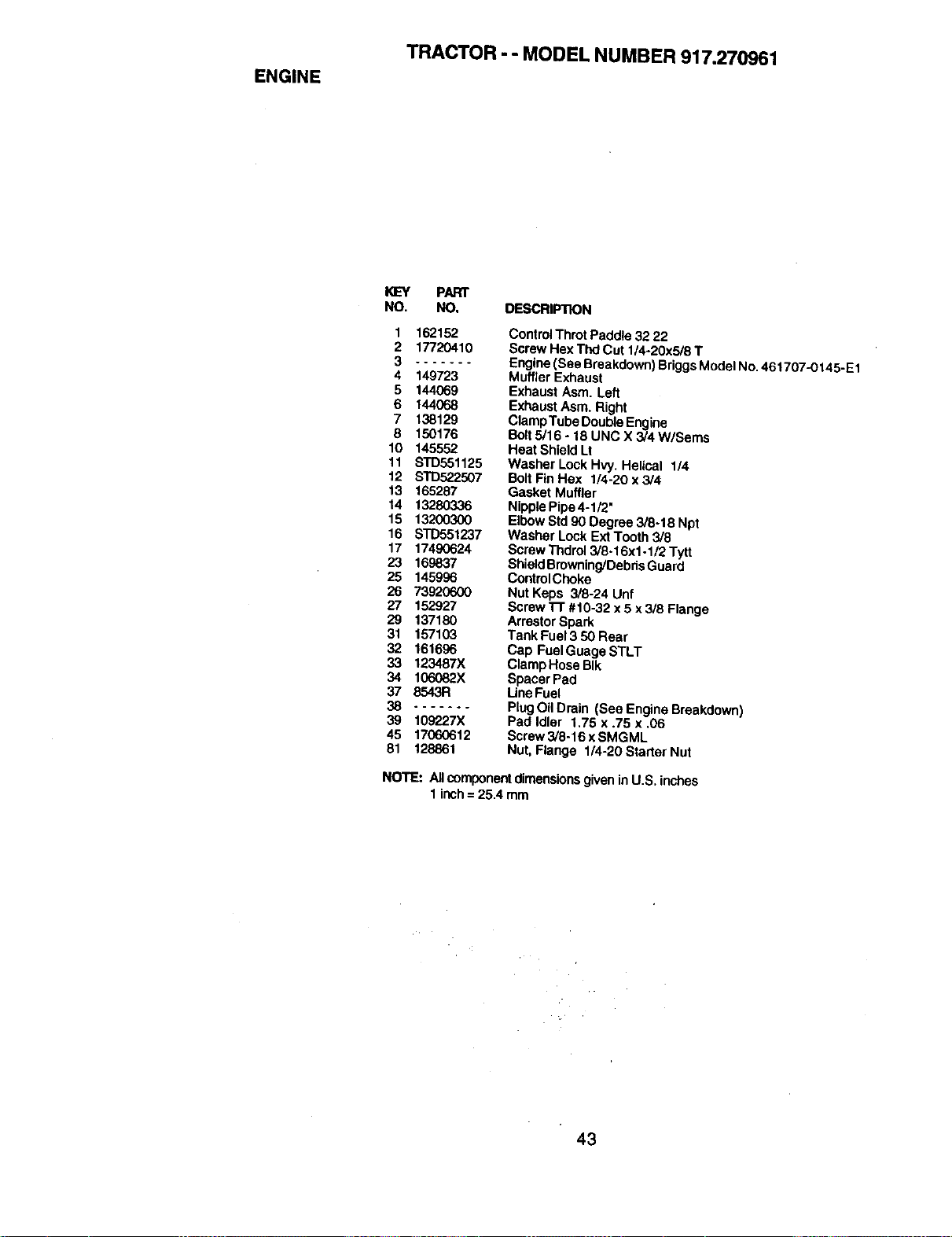
ENGINE
TRACTOR - - MODEL NUMBER 917.270961
_'Y PART
NO. NO. DESCRIPTION
1 162152
2 17720410
3 .......
4 149723
5 144069
6 144O68
7 138129
8 150176
10 145552
11 STD551125
12 ST_o22507
13 165287
14 13280336
15 13200300
16 STD551237
17 17490624
23 169837
25 145996
26 7392(To00
27 152927
29 137180
31 157103
32 161696
33 123487X
34 106082X
37 8543R
38 .......
39 109227X
45 17060612
81 128861
ControlThrotPaddle 32 22
Screw Hex ThdCut 1/4-20x5/8 T
Engine(See Breakdown)Briggs Model No.461707-0145-E1
Muffler Exhaust
Exhaust Asm. Left
Exhaust Asm. Right
ClampTube DoubleEngine
Bolt5/16 - 18 UNC X 3/4 W/Seres
Heat Shield Lt
Washer Lock Hvy. Helical 1/4
Bolt F';nHex 1/4-20 x 3/4
Gasket Muffler
Nipple Pipe 4-1/2"
Elbow Std 90 Degree 3/8-18 Npt
Washer Lock Ext Tooth 3/8
ScrewThdro_3/8-16x1-1/2 Tytt
ShieldBrowning/DebrisGuard
ControlChoke
Nut Keps 3/8-24 Unf
Screwl-r #10-32 x5 x 3/8 Flange
ArrestorSpark
Tank Fuel 3 50 Rear
Cap FuelGuage STLT
ClampHose BIk
Spacer Pad
Line Fuel
PlugOil Drain (See Engine Breakdown)
Pad Idler 1.75 x .75 x ,06
Screw3/8-16 x SMGML
Nut, Flange 1/4-20 Starter Nut
NO'rE: All componentdimensions giveninU.S. inches
1 inch= 25.4 mm
43
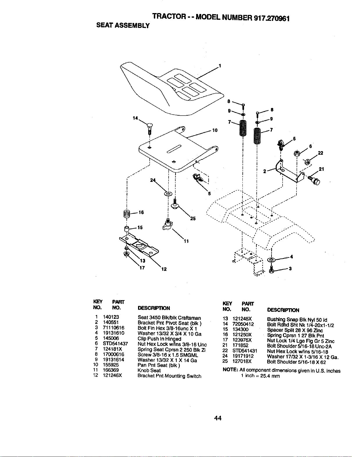
TRACTOR - - MODEL NUMBER 917.270961
SEATASSEMBLY
PART
NO. NO.
1 140123
2 140551
3 71110616
4 19131610
5 145006
6 STD541437
7 124181X
8 17000616
9 19131614
10 155926
11 166369
12 121246X
KEY PART
DESCRIPTION NO. NO. DESCRIP/1ON
Seat 3450 BIk/blkCraftsman
Bracket Pnt PivotSeat (blk }
BoltFin Hex 3/8-16uoc X 1
Washer 13/32 X 3/4 X 10 Ga
Clip Push In Hinged
Nut Hex Lock w/Ins 3/8-16 Unc
Spring Seat Cprsn 2 250 BIk Zi
Screw 3/8-16 x 1,5 SMGML
Washer 13/32 X 1X 14 Ga
Pan Pnt Seat (blk)
KnobSeat
Bracket Pnt MountingSwitch
13 121248X
14 72050412
16 134300
16 121250X
17 123976X
21 171852
22 STD541431
24 19171912
25 127018X
BushingSnap BIk Ny150 Id
BoltRdhd Sht Nk 1/4-20x1-1/2
Spacer Split28 X 96 Zinc
Spdng Cprsn 1 27 BIk Pnt
Nut Lock 114Lge Fig Gr 5 Zinc
BoltShoulder5/16-18 Unc-2A
Nut Hex Lockw/Ins 5/16-18
Washer 17/32 X 1-3/16 X 12 Ga.
Bolt Shoulder5/16-18 X 62
NOTE: All componentdimensionsgivenin U,S. inches
I inch = 25.4 mm
44
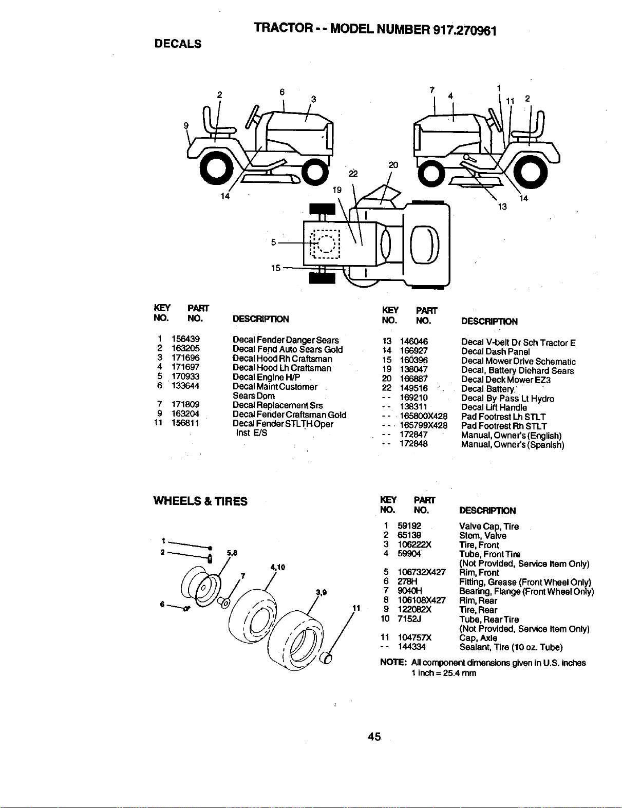
DECALS
TRACTOR -- MODEL NUMBER 917.270961
14
6 7 1
3 4 11 2
22
19
20
14
13
PART
NO. NO.
1 156439
2 163205
3 171696
4 171697
5 170933
6 133644
7 171809
9 163204
11 156811
PART
DESCRIPRON NO. NO. DESCRIPTION
Decal FenderDangerSears 13 146046
Decal Fend Auto Sears Go d 14 166927
Decal Hood Rh Craftsman 15 160396
Decal Hood LhCraftsman 19 138047
Decal EngineH/P 20 166887
Decal MaintCustomer 22 149516 .
SearsDom - - 169210
DecalReplacementSrs - - 138311
DecalFenderCmftsmanGold - - 165800X428
Decal FenderSTLTH Oper -_ 165799X428
Inst E/S - - 172847
- - 172848
Decal V-belt Dr SchTractor E
Decal Dash Panel
Decal Mower DdveSchematic
Decal, Battery Diehard Sears
Decal Deck Mower EZ3
Decal Battery
Decal By Pass LtHydro
Decal LiftHandle
Pad FootrestLhSTLT
Pad FootrestRh STLT
Manual, Owner's(English)
Manual, Owner's (Spanish)
WHEELS & TIRES
2_ 5,0
4,10
11
KEY PAR)"
NO. NO. DESCRIPTION
1
2
3
4
5
6
7
8
9
10
11
59192 Valve Cap, Tire
65139 Stem, Valve
106222X Tire, Front
59904 Tube, FrontTire
(Not Provided, Service Item Only)
106732X427 Rim,Front
278H Fitting,Grease (Front Wheel Only)
9040H Beadng,Flange (FrontWheel Only)
106108X427 Rim,Rear
122082X Tire, Rear
7152J Tube, RearTire
(Not Provided, Service Item Only)
104757X Cap, Axle
144334 Sealant, Tire (10 oz. Tube)
NOTE: All componentdimensionsgivenin U.S. inches
1 inch= 25.4 mm
45
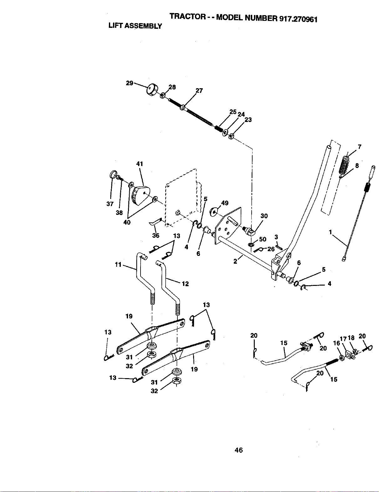
TRACTOR - - MODEL NUMBER 917.270961
LIFTASSEMBLY
29_
27
23
7
30
_j50 3
6
5
4
2O
46
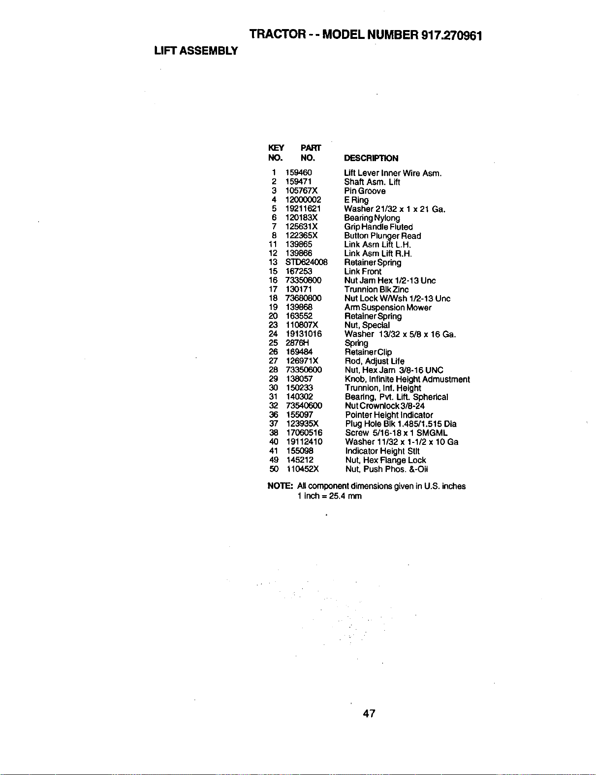
TRACTOR - - MODEL NUMBER 917.270961
LIFT ASSEMBLY
KEY PARr
NO. NO. DESCRIPTION
1 159460 Lift Lever inner Wire Asm.
2 159471 Shaft Asm. Lift
3 105767X Pin Groove
4 12000002 E Ring
5 19211621 Washer 21/32 x 1 x 21 Ga.
6 120183X Beadng Nylong
7 125631X Grip Handle Fluted
8 122365X ButtonPlungerRead
11 139865 LinkAsm Lift L.H.
12 139866 LinkAsm Lift R.H.
13 STD624008 Retainer Spring
15 167253 LinkFront
16 73350800 Nut Jam Hex 1/2-13 Unc
17 130171 TrunnionBIkZinc
18 73680800 Nut LookW/Wsh 1/2-13 Unc
19 139868 ArmSuspensionMower
20 163552 RetainerSpring
23 110807X Nut,Special
24 19131016 Washer 13/32x5/8x16Ga.
25 2876H Spdng
26 169484 RetainerClip
27 126971X Rod, Adjust Life
28 73350600 Nut, HexJam 3/8-16UNC
29 138057 Knob, InfiniteHeightAdmustment
30 150233 Trunnion,Inf. Height
31 140302 Bearing, Pvt. Lift. Sphedcal
32 73540600 Nut Crownlock3/8-24
36 155097 PointerHeight Indicator
37 123935X Plug Hole BIk 1,485/1.515 Dla
38 17060516 Screw 5/16÷18 x I SMGML
40 19112410 Washer 11/32 x 1-1/2 x 10 Ga
41 155098 IndicatorHeight Stlt
49 145212 Nut, Hex Flange Look
50 110452X Nut, Push Phos. &-Oil
NOTE: AllcomponentdimensionsgiveninU.S. inches
1 inch= 25.4 mm
47
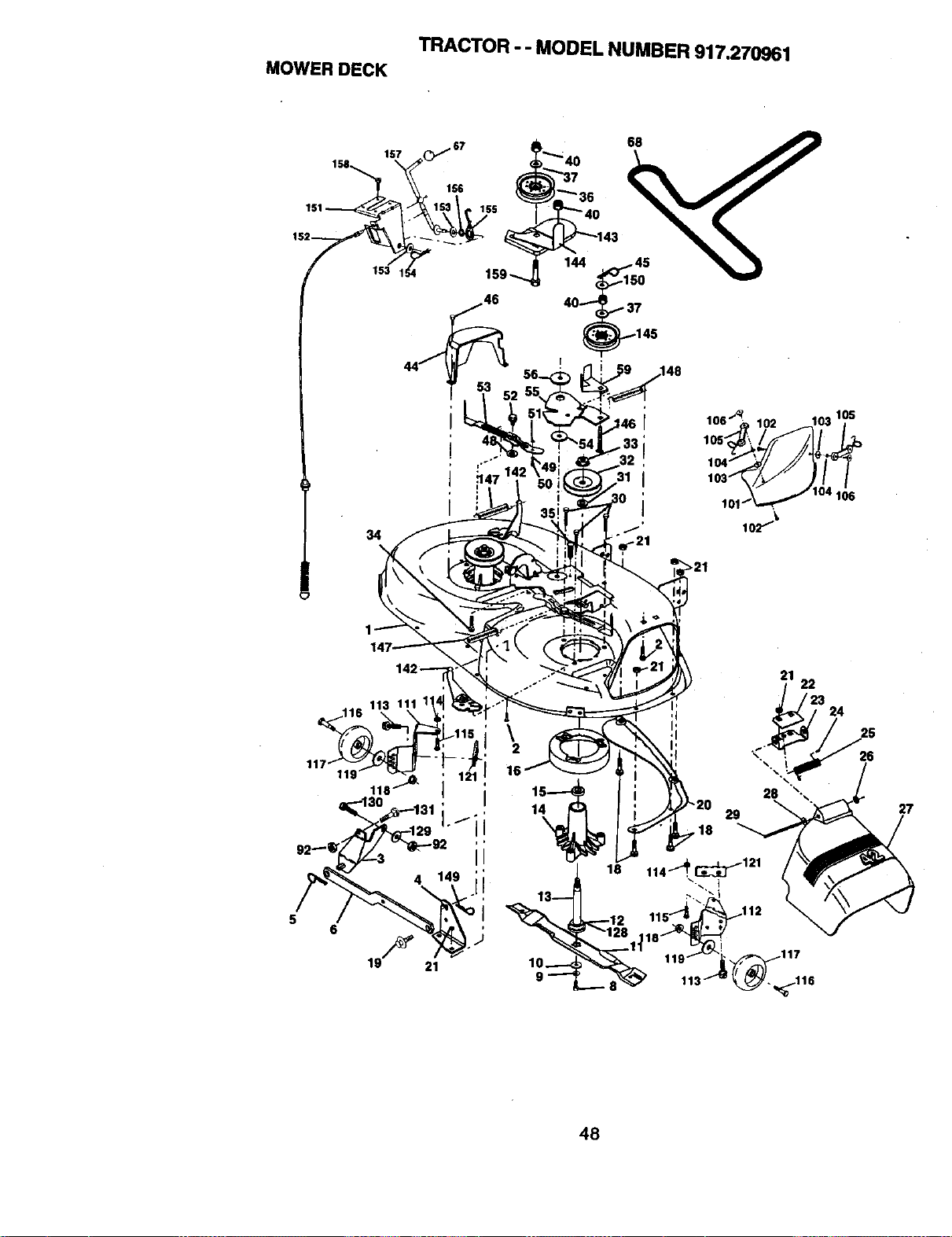
MOWERDECK
TRACTOR - - MODEL NUMBER 917.270961
[
.148
22
24
26
27
48
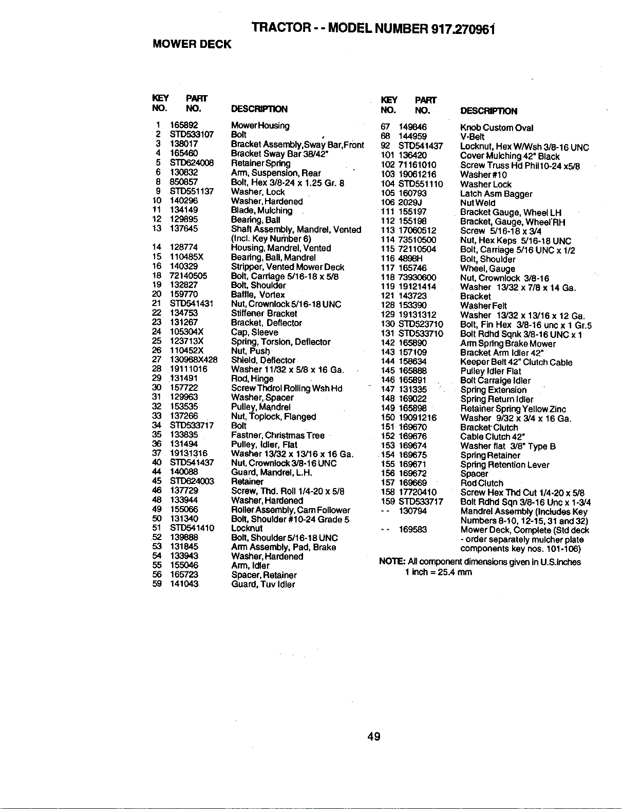
MOWER DECK
TRACTOR - - MODEL NUMBER 917.270961
PART
NO. NO.
1 165892
2 STD533107
3 138017
4 165460
5 STD624008
6 130832
8 850857
9 STD551137
10 140296
11 134149
12 129895
13 137645
14 128774
15 110485X
16 140329
18 72140505
19 132827
20 159770
21 STD541431
22 134753
23 131267
24 105304X
25 123713X
26 110452X
27 130968X428
28 19111016
29 131491
30 157722
31 129963
32 153535
33 137266
34 STD533717
35 133835
36 131494
37 19131316
40 STD541437
44 140088
45 STD624003
46 137729
48 133944
49 155066
50 131340
51 STD541410
52 139888
53 131845
54 133943
55 155046
56 165723
59 141043
KEY PART
DESCRIPTION NO. NO. DESCRIPTION
MowerHousing
Bolt
BracketAssembly,Sway Bar,Front
Bracket Sway Bar 38/42"
RetainerSpdng
Arm,Suspension, Rear
Bolt, Hex 3/8-24 x 1.25 Gr. 8
Washer, Lock
Washer, Hardened
Blade,Mulching
Beadng,Ball
ShaftAssembly, Mandrel, Vented
(IncLKey Nurnber 6)
Housing,Mandrel,Vented
Bearing,Ball, Mandrel
Stripper,Vented Mower Deck
Bolt, Carriage 5/16-18 x 5/8
Bolt, Shoulder
Baffle, Vortex
Nut,Crownlock5/16-18 UNC
StiffenerBracket
Bracket, Deflector
Cap, Sleeve
Spring,Torsion, Deflector
Nut, Push
Shield, Deflector
Washer 11/32 x 5/8 x 16 Ga.
Rod,Hinge
ScrewThdrel RollingWsh Hd
Washer, Spacer
Pulley,Mandrel
Nut,Toplock;Flanged
Bolt
Fastner,Christmas Tree
Pulley, Idler, Flat
Washer 13/32 x 13/16 x 16 Ga.
Nut,Crownlock3/8-16 UNC
Guard, Mandrel, L.H.
Retainer
Screw, Thd. Roll 1/4-20 x 5/8
Washer,Hardened
RollerAssembly,Cam Follower
Bolt,Shoulder#10-24 Grade 5
Locknut
Bolt, Shoulder5/16-18 UNC
Arm Assembly, Pad, Brake
Washer,Hardened
Arm, Idler
Spacer, Retainer
Guard, Tuv Idler
67 149846
68 144959
92 STD541437
101 13642O
102 71161010
103 19061216
104 STD551110
105 160793
106 2029J
111 155197
112 155198
113 17060512
114 73510500
115 72110504
116 48981"1
117 165746
118 739306o00
119 19121414
121 143723
128 153390
129 19131312
130 STD523710
131 ST0533710
142 165890
143 157109
144 158634
145 165888
146 165891
147 131335
148 169022
149 165898
!50 1£091216
151 169670
152 169676
153 169674
154 169675
155 169671
156 169672
157 169669
158 17720410
159 STD533717
- - 130794
- - 169583
KnobCustom Oval
V-Belt
Locknut,Hex WANsh 3/8-16 UNC
Cover Mulching42" Black
ScrewTruss Hd Philt0-24 x5/8
Washer#10
Washer Lock
LatchAsm Bagger
NutWeld
Bracket Gauge, Wheel LH
Bracket,Gauge, Wheel'RH
Screw 5/16-18 x 3/4
Nut,Hex Kepe 5/16-18 UNC
Bolt,Carriage 5/16 UNC x 1/2
Bolt,Shoulder
Wheel, Gauge
Nut,Crownldck 3/8-16
Washer 13/32 x 7/8 x 14 Gs.
Bracket
Washer Felt
Washer 13/32 x 13/16x 12 Ga.
Bolt, Fin Hex 3/8-16 unc x 1 Gr.5
Bolt Rdhd Sqnk 3/8-16 UNC x 1
Arm SpringBrake Mower
Bracket Arm Idler 42"
Keeper Belt42" ClutchCable
Pulley Idler Flat
BoltCarraige Idler
Spring Extension
SpdngReturn Idler
Retainer SpdngYellowZinc
Washer 9/32 x 3/4 x 16 Ga.
Bracket Clutch
Cable Clutch42"
Washer flat 3/8" Type B
SpdngRetainer
SpdngRetention Lever
Spacer
RodClutch
Screw Hex Thd Cut 1/4-20 x 5/8
BoltRdhd Sqn 3/8-16 Uncx 1-3/4
Mandrel Assembly(IncludesKey
Numbers8-10, 12-15, 31 and 32)
Mower Deck, Complete (Std deck
- order separately mulcher plate
componentskey nos. 101-106)
NOTE: AllcomponentdimensionsgiveninU.S.inches
1 inch= 25.4 mm
49
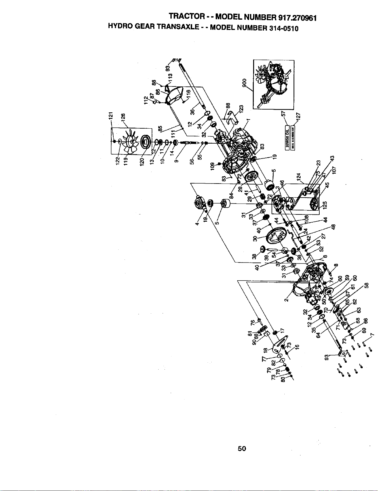
TRACTOR - - MODEL NUMBER 917.270961
HYDRO GEAR TRANSAXLE - - MODEL NUMBER 314-0510
co
\
04
\
5O
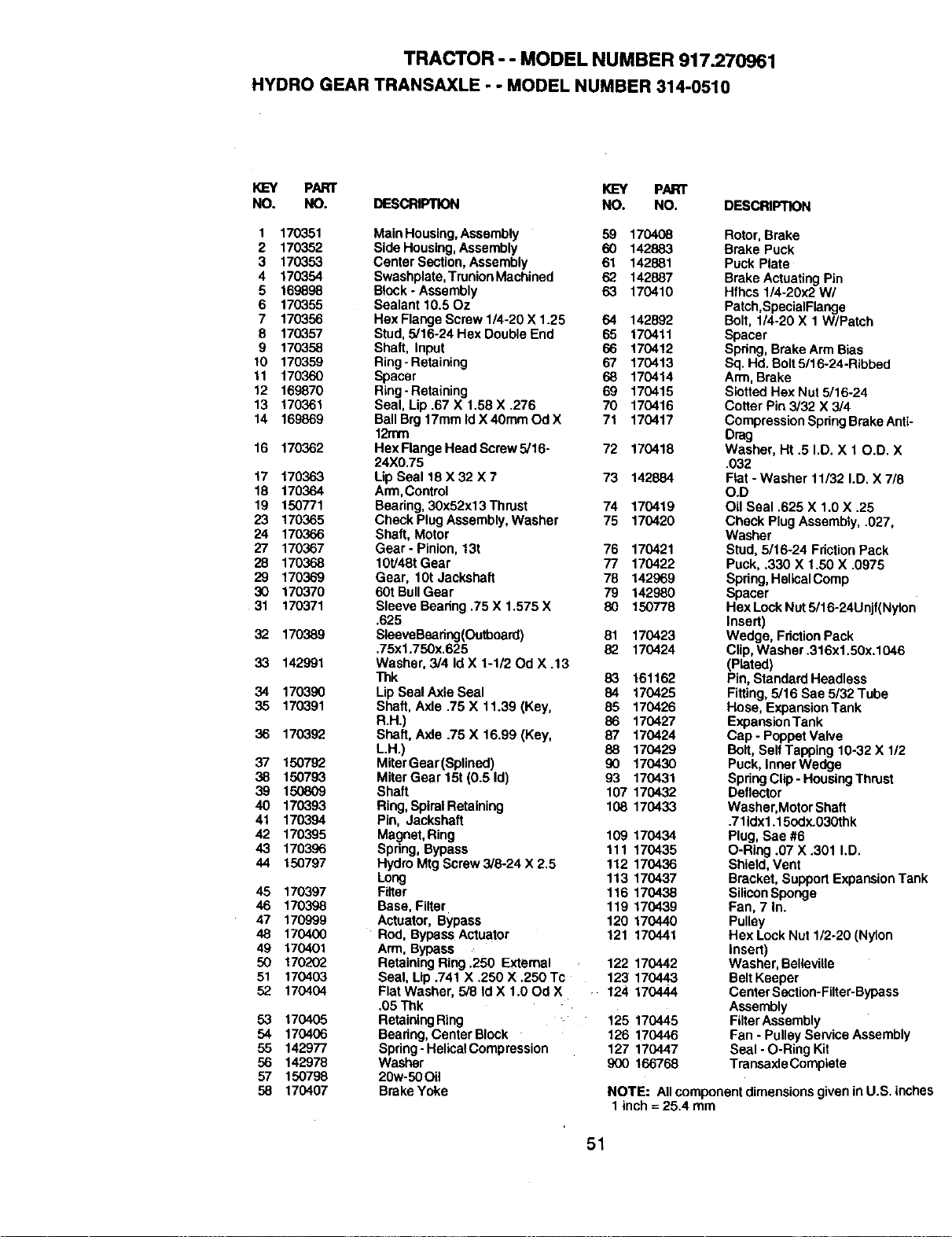
TRACTOR- - MODEL NUMBER 917.270961
HYDRO GEAR TRANSAXLE . - MODEL NUMBER 314-0510
KL=Y PAR)" I<LcY PART
NO. NO. DESCRIPTION NO. NO. DESCRIPTION
1 170351
2 170352
3 170353
4 170354
5 169898
6 170355
7 170356
8 170357
9 170358
10 170359
11 170360
12 169870
13 170361
14 169869
16 170362
17 170363
18 170364
19 150771
23 170365
24 170366
27 170367
28 170368
29 170369
30 170370
31 170371
32 170389
33 142991
34 170390
35 170391
36 170392
37 150792
38 150793
39 150809
40 170393
41 170394
42 170395
43 170396
44 150797
45 170397
46 170398
47 170999
48 170400
49 170401
50 170202
51 170403
52 170404
53 170405
54 170406
55 142977
56 142978
57 150798
58 170407
Main Housing,Assembly
Side Housing,Assembly
Center Section, Assembly
Swashplate,TrunionMachined
Block - Assembly
Sealant 10.50z
Hex Flange Screw 1/4-20 X 1.25
Stud, 5/16-24 Hex DoubleEnd
Shaft, Input
Ring -Retaining
Spacer
Ring-Retaining
Seal, Lip .67 X 1.58 X .276
BallBrg 17mm Id X 40mm Od X
12mm
Hex FlangeHead Screw 5/16-
24X0.75
Lip Seal 18 X 32 X 7
Arm,Control
Bearing, 30x52x13 Thrust
Check PlugAssembly, Washer
Shaft, Motor
Gear - Pinion,13t
10t/48t Gear
Gear, 10t Jackshaft
60t BullGear
Sleeve Bearing .75 X 1.575 X
.625
SleeveBearing(Outboard)
,75xl .750x.625
Washer, 3/4 Id X 1-1/20d X .13
"l_k
Lip SealAxle Seal
Shaft, Axle .75 X 11.39 (Key,
R.H.)
Shaft, Axle .75 X 16,99 (Key,
LH.)
MiterGear (Splined)
Miter Gear 15t (0.5 Id)
Shaft
Ring, SpiralRetaining
Pin, Jackshaft
Magnet,Ring
Spring, Bypass
Hydro Mtg Screw 3/8-24 X 2.5
Long
Filter
Base, Filter
Actuator, Bypass
Rod, Bypass Actuator
Arm, Bypass
RetainingRing .250 External
Seal, Lip .741 X .250 X .250 TC
Flat Washer, 5/8 Id X 1.00d X
.05 Thk
RetainingRing
Bearing, Center Block
Spring -HelicalCompression
Washer
20w-50Oil
Brake Yoke
59 170408 Rotor, Brake
60 142883 Brake Puck
61 142881 Puck Plate
62 142887 Brake ActuatingPin
63 170410 Hfhcs 1/4-20x2W/
Patch,SpacialFlange
64 142892 Bolt, 1/4-20 X 1 W/Patch
65 170411 Spacer
66 170412 Spring, Brake Arm Bias
67 170413 Sq. Hd. Bolt5/16-24-Ribbed
68 170414 Arm, Brake
69 170415 Slotted Hex Nut 5/16-24
70 170416 Cotter Pin3/32 X 3/4
71 170417 Compression SpdngBrake Anti-
Drag
72 170418 Washer, Ht .5 I.D. X 10.D. X
.032
73 142884 Flat - Washer 11/32 I.D. X 7/8
O.D
74 170419 Oil Seal .625 X 1.0 X .25
75 170420 Check Plug Assembly, .027,
Washer
76 170421 Stud, 5/16-24 Friction Pack
77 170422 Puck, .330 X 1.50 X .0975
78 142969 Spring,HelicalComp
79 142980 Spacer
80 150778 Hex LockNut 5/16-24Unjf(Nylon
Insert)
81 170423 Wedge, FrictionPack
82 170424 Clip,Washer .316x1.50x.1046
(Plated)
83 161162 Pin, StandardHeadless
84 170425 Fitting,5/16 Sae 5/32 Tube
85 170426 Hose, ExpansionTank
86 170427 ExpansionTank
87 170424 Cap- Poppet Valve
88 170429 Bolt, SelfTapping 10-32 X 1/2
90 170430 Puck, InnerWedge
93 170431 Spring Clip -HousingThrust
107 170432 Deflector
108 170433 Washer, MotorShaft
.71idx1.15odx.03Othk
109 170434 Plug, Sae #6
111 170435 O-Ring .07 X .301 I,D.
112 170436 Shield, Vent
113 170437 Bracket, SupportExpansionTank
116 170438 SiliconSponge
119 170439 Fan, 7 In.
120 170440 Pulley
121 170441 Hex Lock Nut 1/2-20 (Nylon
insert)
122 170442 Washer, Bellaville
123 170443 Belt Keeper
124 170444 Center Section-Filter-Bypass
Assembly
125 170445 FUterAssembly
126 170446 Fan- PulleyService Assembly
127 170447 Seal -O-Ring Kit
900 166768 Transaxle Comptete
NOTE: All component dimensionsgiven inU.S. inches
1inch = 25.4 mm
51
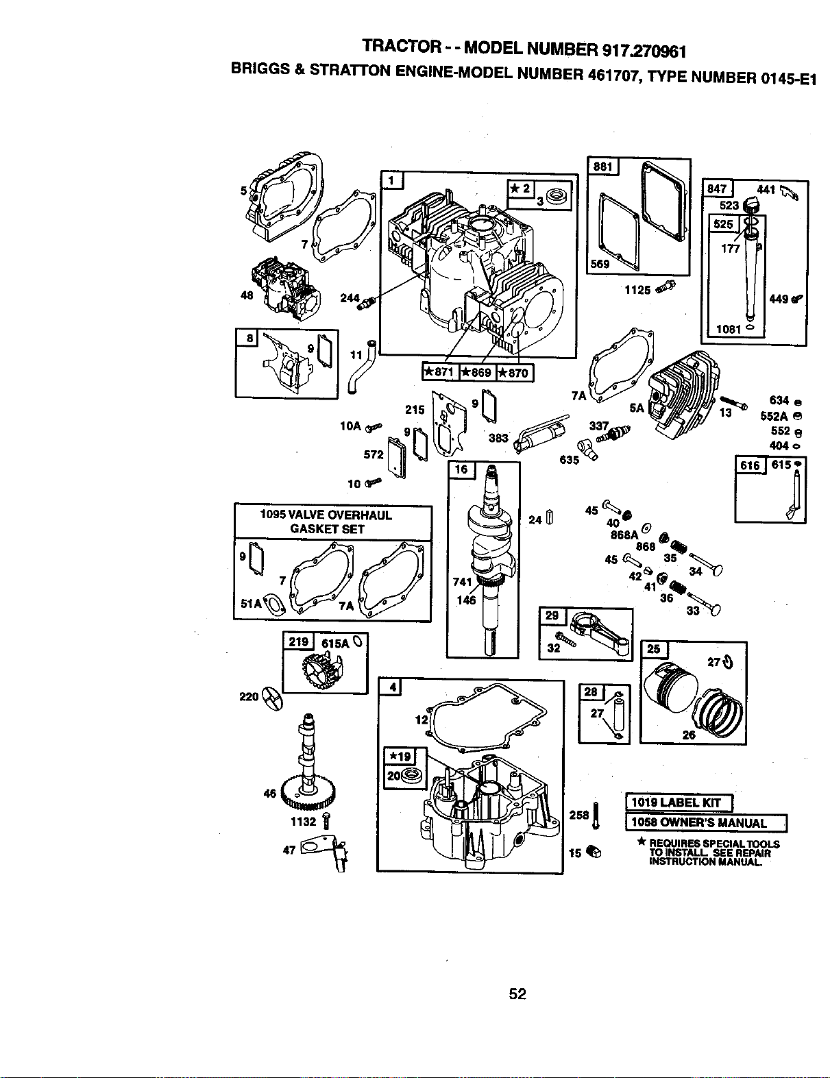
TRACTOR - - MODEL NUMBER 917.270961
BRIGGS & STRATTON ENGINE-MODEL NUMBER 461707, TYPE NUMBER 0145-E1
5
572
1095 VALVE OVERHAUL
GASKET SET
61SA_/
1132 _
1125_
t9 _'
26
258A [ 1019 LABEL KIT I
I 1058 OWNER'S MANUAL 'l
"k REQUIRES SPECIALTOOLS
15 _ TOINSTALL SEE REPAIR
INSTRUCTION MANUAl
52
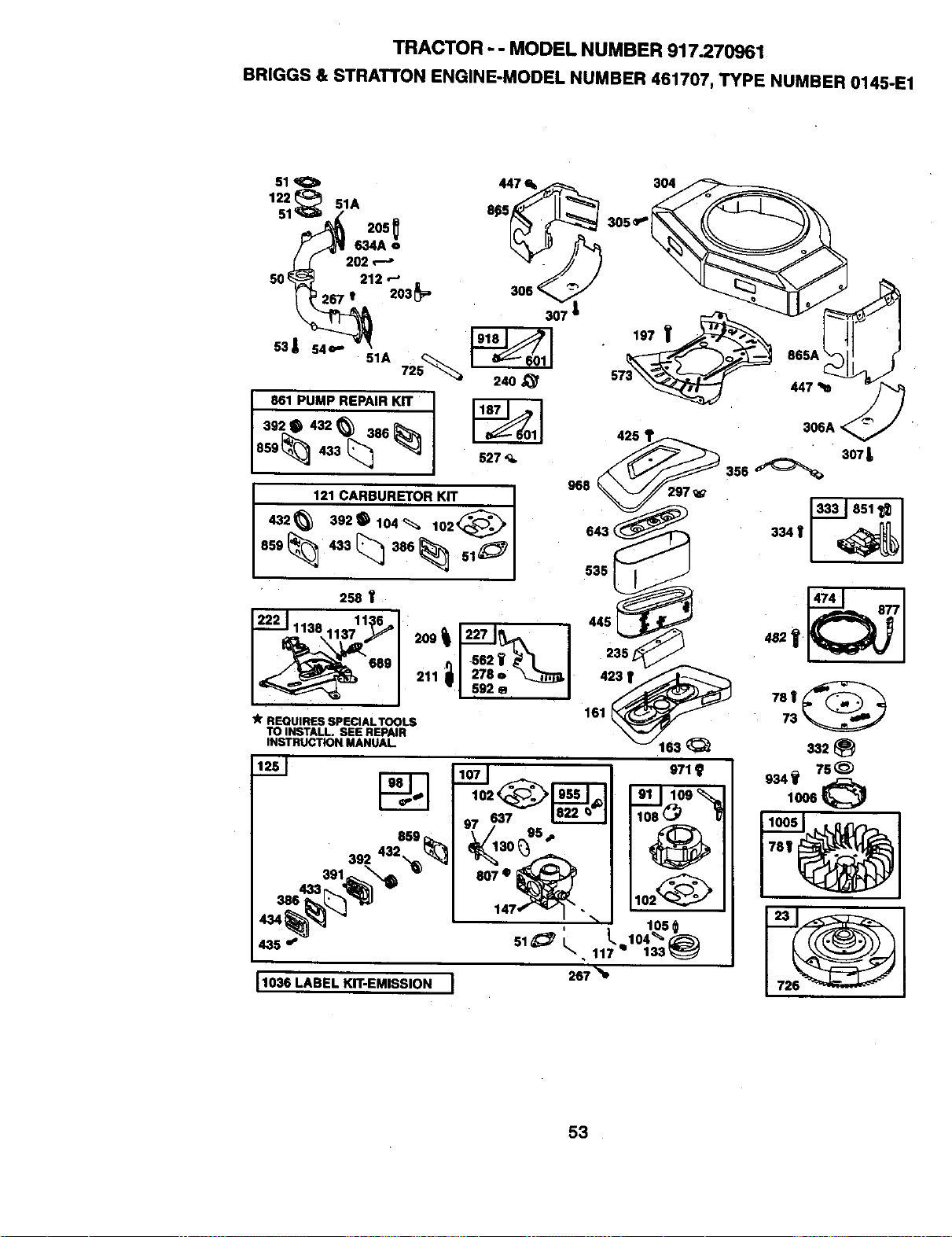
TRACTOR- - MODELNUMBER 917.270961
BRIGGS& STRATTONENGINE-MODELNUMBER461707,TYPENUMBER0145-E1
85g
392,32_
391 _
435 _
971
267_e
1036 LABEL KIT-EMISSION I
53
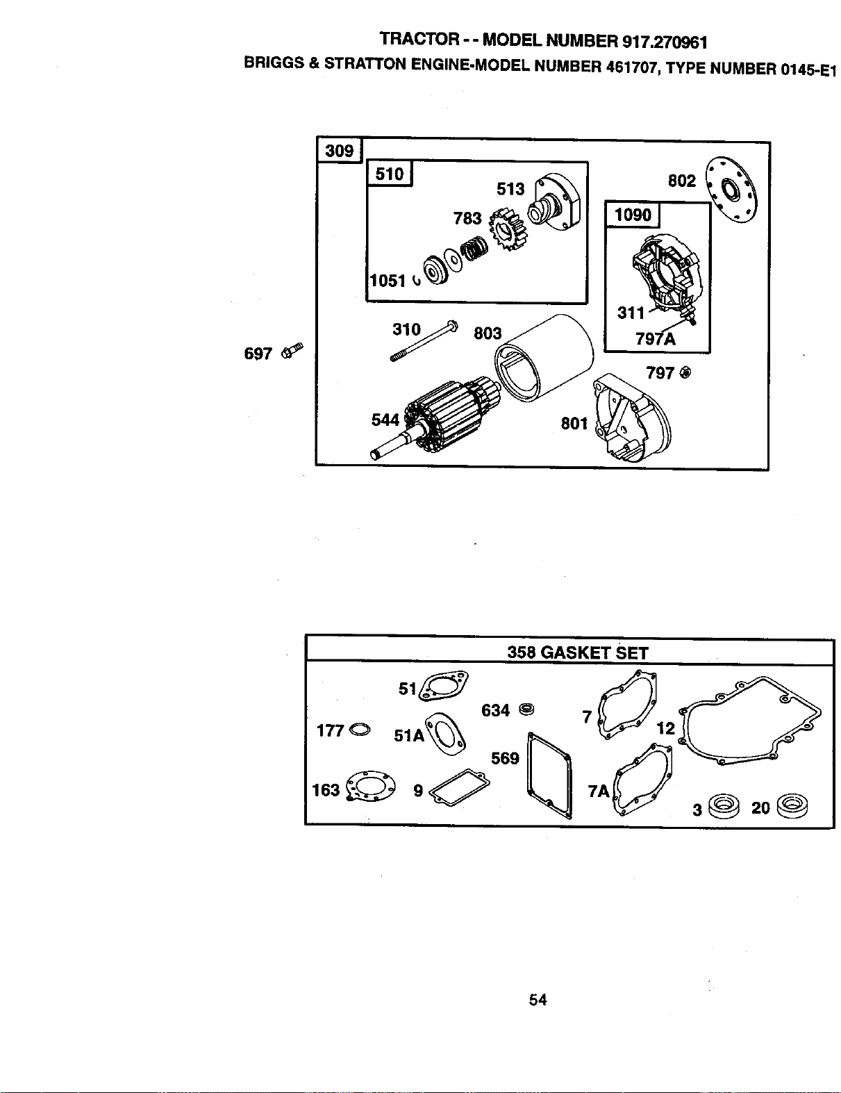
TRACTOR - - MODEL NUMBER 917.270961
BRIGGS & STRATTON ENGINE-MODEL NUMBER 461707, TYPE NUMBER 0145.
697
309
101 513_
1051 _ _)1_ "_d!_
y 803
544 _
801
797
358 GASKET SET
177 O 51A_
38 208
54

TRACTOR - - MODEL NUMBER 917.270961
BRIGGS & STRATTON ENGINE-MODEL NUMBER 461707, TYPE NUMBER 0145-E1
KEY PART KEY PART
NO. NO. DESCRIPTION NO. NO. DESCRIPTION
1 496583
2 399265
3 91086
4 493304
5 214517
5A 214518
7 271867
7A 271868
8 495754
9 27803
10 94382
10A 94380
11 280225
273390
13
15
16
19
2O
23
24
25
26
27
28
29
32
33
34
35
36
4O
41
42
45
46
47
48
50
51
51A
53
54
73
75
78
91
271188
271189
94565
94239
690666
399264
291675
491180
222698
499180
499181
499182
499183
499184
499285
499186
499187
263129
496319
496320
496314
498541
95017
390420
4945.53
691302
65906
26828
221596
2o__260
494553
261368
214487
393415
496542
21329O
271412
270884
93970
93208
691438
222511
691134
693483
Cylinder Assembly
Bushing/SealKit
•/r Seal-Oil
Sump-Eng_e
Head-Cylinder#1
Head-Cylinder#2
Gasket-CylinderHead #1
Gasket-CylinderHead#2
BreatherAssembly(Cylinder#1)
Gasket-Breather
Screw(BreatherAssembly)
Screw (BreatherCover)
Tube-Breather
./_Gasket-Crankcase (.015" Thick,
Std.)
•k Gasket-Crankcase (.005" Thick)
,/r Gasket-Crankcase (.009" Thick)
Screw(Cylinder Head)
Rug-Oil Drain
Crankshaft
Bushing
Seal-Oil
Flywhe_
Key-Flywheel
PistonAssembly(Standard)
Piston Assembly (.010 "O.S.)
Piston Assembly(.020" O.S.)
Piston Assembly (.030" O.S.)
Ring Set, Piston(Standard)
Ring Set, Piston (.010 "O,S,)
Ring Set, Piston (.020 "O,S,)
Ring Set, Piston (.030 "O.S.)
Lock-PistonPin
PinAssembly,Piston (Std.)
PinAssembly-Piston(.005"
O.S.)
Rod-Connecltng (Standard)
Rod-Connecting(.020 U.S.)
Screw (ConnectingRod)
Valve-Exhaust(Include(s):
Keepar-Valve(Ref, No,42))
Valve-Intake
Spring-Valve(Intake)
Spring-Valve(Exhaust)
Retainer-Valve(Exhaust)
Retainer-Valve(Extlaust)
Keeper-Valve
Tappet-Valve
Camshaft
Slinger-Oil
ShortBlock
Manltold-lntake
Gasket-intake
Gasket-Intake
Screw (Carburetor)
Screw (IntakeManifold)
Screen-Rotating
Washer(Flywheel)
Screw (FlywheelFan)
Body Assembly-Upper
95 690718 Screw(ThmttieValve)
97 693485 Shaft-Throttle
98 807923 Kit-ldieSpeed
102 69G509 • Gasket-CarburetorBody
104 69_506 • Pin-FloatHinge
105 692078 • Valve-Float Needle
107 693482 BodyAssembly-Lower
108 693505 Valve-Choke
109 693498 Shaft-Choke
117 693538 Jet*Main
693500 Jet-Main(High Altitude)
121 491539 CarburstorKit
122 281411 Spacer
125 693479 Carburetor
130 693504 Valve-Thmtlte
133 693512 Fk_at-Carburetor
146 94196 Key-Timing
147 693506 Jet-Pilot
161 496599 Baea-AirCleaner
163 271411 * Gasket-AirCleaner
177 271170 "JrSeal.O-Ring
187 299146 Line-Fuel(CuttoRequired
Length)
197 95063 Screw (BackPlate)
202 262683 Link-MechanicalGovernor
203 280997 Crank-Ben
205 93971 Screw (BellCrank)
209 262352 Spring-Governor
211 261563 Spring-Governor
212 693985 Link-Throttle
215 224816 Guide-Air
219 3.94348 Gear-Governor
220 222773 Washer-Thrust(GovernorGear)
222 491282 Bracket-Contrel
227 491297 Lever-Governor
235 224995 Shield-FuelSpray
240 394358 Filter-Fuel
244 230318 Connestor-Hose(PulseUne)
258 94930 Screw(EngineSump)
267 93897 Screw (CasingClamp)
278 94942 Washer (GovernorLever)
297 94289 Nut-Wing(AirFilterRetainer)
304 691390 Housklg-Blower
305 690960 Screw (BlowerHousing)
306 222846 Shield-Cylinder
306A 223734 Shield-Cylinder
307 94930 Screw (CylinderShield)
309 497596 Motor-Starter
310 94003 Bolt (Starter Motor)
311 497608 Brush Set
332 230674 Nut(Flywheel)
• 333 394891 Armature-Magneto
334 94731 Screw(MagnetoArmature)
337 802592 Plug-Spark
356 494705 Wire-Stop
358 495868 Gasket Set
383 89838 Wrench-Spark Plug
386 693490 0+ Gasket-pump
391 693487 Body-Pump
392 693491 •+ Spring-Pump Diaphragm
55
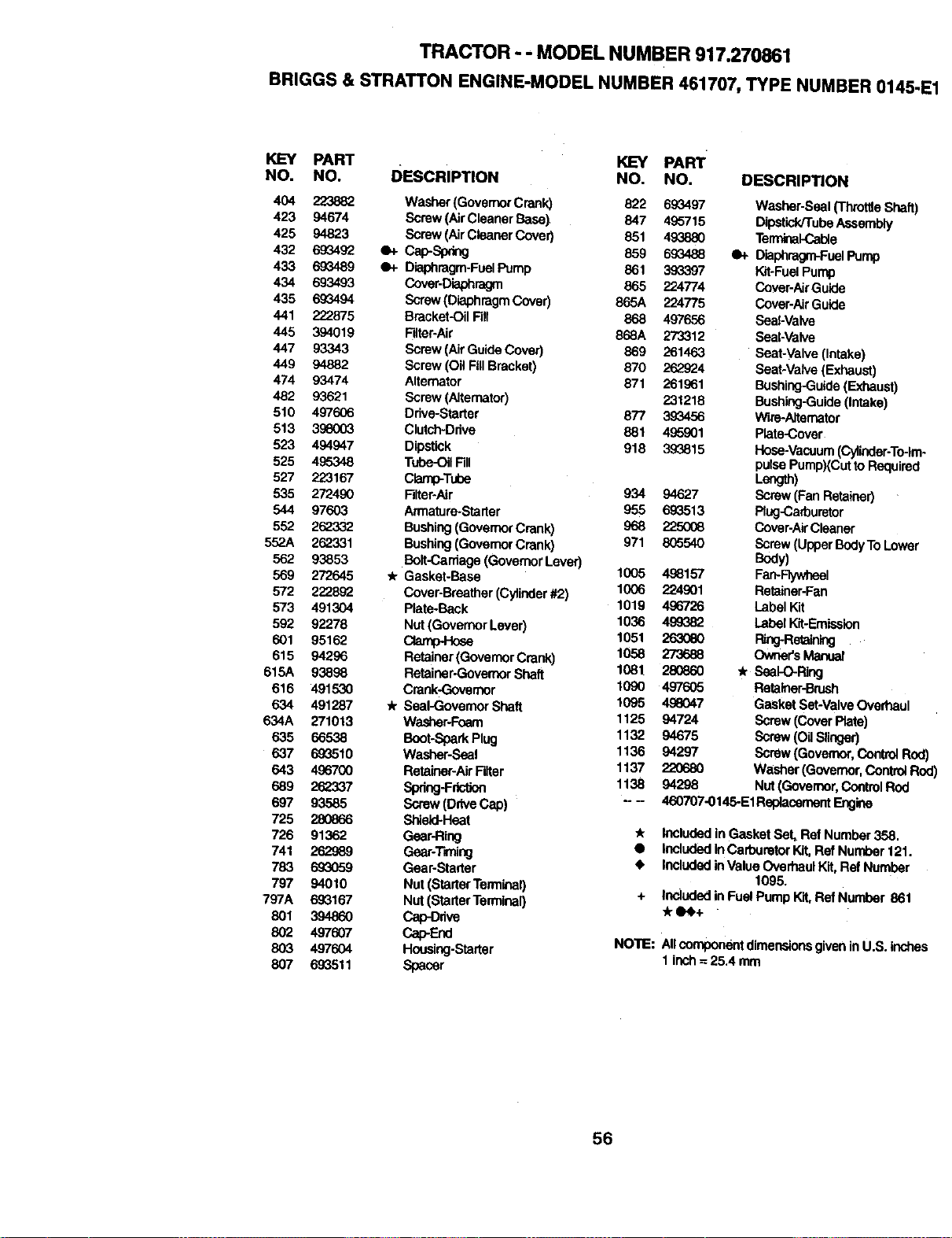
TRACTOR - - MODEL NUMBER 917.270861
BRIGGS & STRATTON ENGINE-MODEL NUMBER 461707,TYPE NUMBER 0146-1
KEY PART KEY PART
NO. NO. DESCRIPTION NO. NO. DESCRIPTION
404 223882 Washer(GovernorCrank) 822 693497 Washer-Seal(ThrottleShaft)
423 94674 Screw(AirCleaner BaseI 847 495715 Dipstick/TubeAssembly
425 94823 Screw(AirCleanerCover) 851 493880 Terminal-Cable
432 693492 Q+ Cap-Spring 859 693488 e+ Diaphragm-FuelPump
433 693489 4)+ Diaphragm-FuelPump 861 39_397 Kit-FuelPump
434 693493 Cover-Diaphragm 865 224774 Cover-AirGulde
435 693494 Screw(DiaphragmCover) 865A 224775 Cover-AirGuide
441 222875 Bracket-OilFill 868 497656 Seal-Valve
445 394019 Filter-Air 868A 273312 Seal-Valve
447 93343 Screw (AirGuideCover) 869 261463 Seat-Valve(Intake)
449 94882 Screw (Oil FillBracket) 870 262924 Seat-Valve(Exhaust)
474 93474 Alternator 571 261961 Bushing-Guide(Exhaust)
482 93621 Screw (Alternator) 231215 Bushing-Guide(Intake)
510 497606 Drive-Starter 877 393456 W_re-Aitemator
513 396003 Clutch-Drive 881 495901 Plate-Cover
523 494947 Dipstick 918 393815 Hose-Vacuum(Cylinder.To-}re.
525 495348 Tube.-C_Fill pulsePumpXCutto Required
527 223167 Clamp-Tuhe Length)
535 272490 Filter-Air 934 94627 Screw (FanRetainer)
544 97603 Armature-Starter 955 693513 Rug-Carburetor
552 262332 Bushing(GovernorCrank) 968 225006 Cover-AirCleaner
552A 262331 Bushing(Goven_ Crank) 971 8(;5540 Screw (UpperBodyToLower
562 93853 Bolt-Carriage(GovernorLever) Body)
569 272645 4r Gasket-Base 1005 498157 FarvRywhsel
572 222892 Cover-Breather(Cylinder#2) 1006 224901 Retainer-Fan
573 491304 Plate-Back 1019 496726 Label Kit
592 92278 Nut (GovernorLaver) 1036 499382 Label Kit-Emission
601 95162 Clarnp4-k_se 1051 263060 Ring-Retaining
615 94296 Retainer(GovemorCrenk) 1058 273688 Owner'sManust
615,6, 93898 Retainer-GovernorSheft 1081 280860 .k Seat-O-Rk_j
616 491530 Crank-Govemor 1090 497605 Retainer-Brush
634 491287 4r Seal-GovernorShaft 1095 496047 Gasket Set-ValveOverhaul
634A 271013 Washer-Foam 1125 94724 Screw (CoverPlate)
635 66538 Boot-SparkPlug 1132 94675 Screw (Oil Slinger)
637 69_510 Washer-Seal 1136 94297 Screw (Governor, CorttrolPod
643 496700 Retainer-AirFilter 1137 220680 Washer(Governor,Control Rc
689 262.337 Spring-Friction 1138 94298 Nut (Governor,ControlRod
697 93585 Screw(DriveCap) -- - 460707-0145.EIReplacement Engine
725 280866 Shlald-Heat
726 91362 Gear-Ring _ Includedin GasketSet, Ref Number358.
741 262989 Gear-T'r_ing • IneludedlnCarburetorKIt, Ref Number121.
783 693059 Gear-Starter • IncludedinValue OverhaulKit,Ref Number
797 94010 Nut (StarterTelminal) 1095.
797A 693167 Nut (StarterTerminal) + Included in FuelPump Kft,Ref Number 861
801 3948_ Cap-_ve
802 497607 Cap-End NOTE: AllcomponentdimensionsgiveninU.S. inches
803 497604 Housing-Starter 1inch -=25,4 mm
807 693511 Spacer
56

57

58

SUGGESTED GUIDE FOR SIGHTING SLOPES FOR SAFE OPERATION
ONLY RIDE UP AND DOWN HILL,
NOT ACROSS HILL
ol
(.0
l& Operate your Tractor up and down the face of slopes (not I
I
greater than 15°), never across the face. Make turns gradu- I
ally to prevent tipping or loss of control. Exercise extreme J
caution when changing direction on slopes. I

For in-home major brand repair service:
Call 24 hoursa day, 7 days a week
1-800-4-MY-HOME s" (1-800-469-4663)
Para pedir servicio de reparaci6n a domicilio
1,800-676-5811
In Canada for all your service and parts needs call
Au Canada pour tout le service ou les pi_ces
1-800-665-4455
For the repair or replacement parts you need:
Call 6 am - 11 pm CST, 7 days a week
PartsDirect sM
1-800-366-PART (1-800-366-7278)
Para ordenar piezas con entrega a domicilio
1-800-659-7084
For the location of a Sears Parts and Repair Center
in your area:
Call 24 hours a day, 7 days a week
1-800-488-1222
For information on purchasing a Sears Maintenance
Agreement or to inquire about an existing Agreement:
Call 9 am - 5 pm, Monday - Saturday
1-800-827-6655
172847 11.10.99 RH Printed in U.S.A.