INSTALLATION AND SERVICE MUST BE PERFORMED BY A QUALIFIED INSTALLER.
IMPORTANT: SAVE FOR LOCAL ELECTRICAL INSPECTOR'S USE.
READ AND SAVE THESE INSTRUCTIONS FOR FUTURE REFERENCE.
Clearances and Dimensions
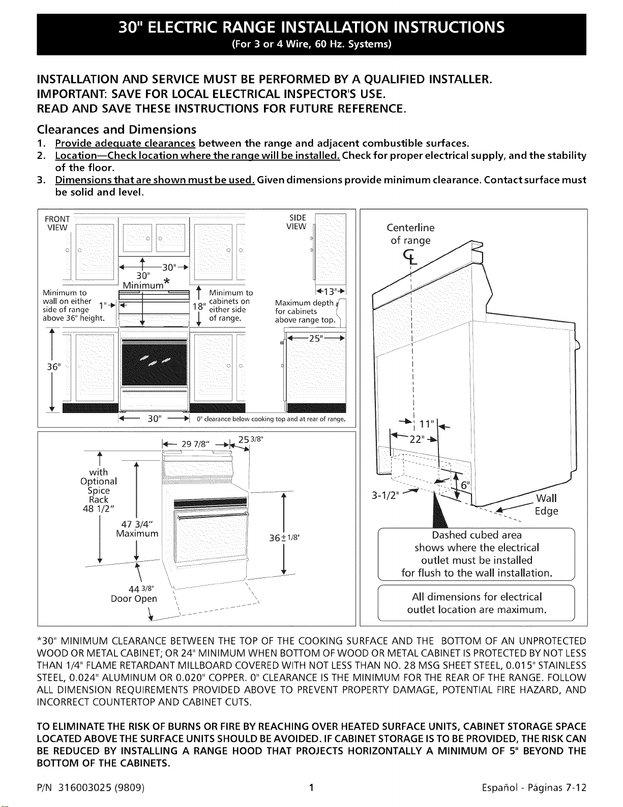
1. Provide adequate clearances between the range and adjacent combustible surfaces.
2. Location--Check location where the ranqe will be installed. Check for proper electrical supply, and the stability
of the floor.
3. Dimensions that are shown must be used. Given dimensions provide minimum clearance. Contact surface must
be solid and level.
..................................
Minimum to T Minimum to
wall on either i" cabinets on
side of range 1 either side
above 36" height, of range.
SIDE
VIEW
I_! 3"-_1
Maximum depth,
for cabinets
above range
r
0" clearance below cooking top and at rear of range.
with
Optional
Spice
Rack
48 1/2"
47 3/4"
Maximum
44 3/8"
Door Open
\
\
\
Centerline
of range
q_
i
Dashed cubed area
shows where the electrical
outlet must be installed
for flush to the wall installation.
All dimensions for electrical
outlet location are maximum.
*30" MINIMUM CLEARANCE BETWEEN THE TOP OF THE COOKING SURFACE AND THE BOTTOM OF AN UNPROTECTED
WOOD OR METAL CABINET; OR 24" MINIMUM WHEN BOTTOM OF WOOD OR METAL CABINET IS PROTECTED BY NOT LESS
THAN 1/4" FLAME RETARDANT MILLBOARD COVERED WITH NOT LESS THAN NO. 28 MSG SHEET STEEL, 0.01 5" STAINLESS
STEEL, 0.024" ALUMINUM OR 0.020" COPPER. 0" CLEARANCE IS THE MINIMUM FOR THE REAR OF THE RANGE. FOLLOW
ALL DIMENSION REQUIREMENTS PROVIDED ABOVE TO PREVENT PROPERTY DAMAGE, POTENTIAL FIRE HAZARD, AND
INCORRECT COUNTERTOP AND CABINET CUTS.
TO ELIMINATE THE RISK OF BURNS OR FIRE BY REACHING OVER HEATED SURFACE UNITS, CABINET STORAGE SPACE
LOCATED ABOVE THE SURFACE UNITS SHOULD BEAVOIDED. IF CABINET STORAGE IS TO BE PROVIDED, THE RISK CAN
BE REDUCED BY INSTALLING A RANGE HOOD THAT PROJECTS HORIZONTALLY A MINIMUM OF 5" BEYOND THE
BOTTOM OF THE CABINETS.
P/N 31 6003025 (9809) 1 Espafiol- Paginas 7-12
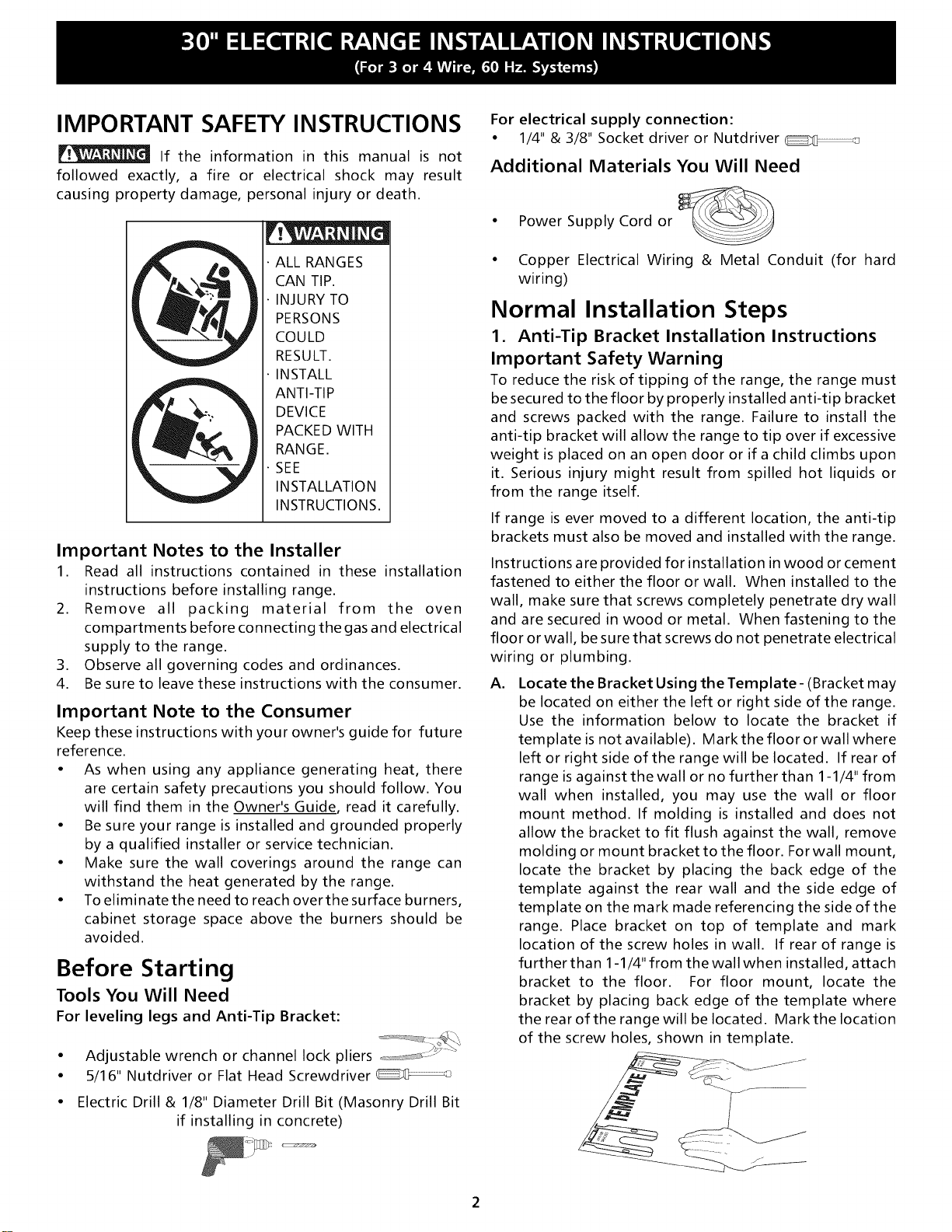
IMPORTANT SAFETY INSTRUCTIONS
If the information in this manual is not
followed exactly, a fire or electrical shock may result
causing property damage, personal injury or death.
ALL RANGES
CAN TIP.
INJURY TO
PERSONS
COULD
RESULT.
INSTALL
ANTI-TIP
DEVICE
PACKED WITH
RANGE.
SEE
INSTALLATION
INSTRUCTIONS.
Important Notes to the Installer
1. Read all instructions contained in these installation
instructions before installing range.
2. Remove all packing material from the oven
compartments before connecting the gas and electrical
supply to the range.
3. Observe all governing codes and ordinances.
4. Be sure to leave these instructions with the consumer.
Important Note to the Consumer
Keep these instructions with your owner's guide for future
reference.
• As when using any appliance generating heat, there
are certain safety precautions you should follow. You
will find them in the Owner's Guide, read it carefully.
• Be sure your range is installed and grounded properly
by a qualified installer or service technician.
• Make sure the wall coverings around the range can
withstand the heat generated by the range.
• To eliminate the need to reach over the surface burners,
cabinet storage space above the burners should be
avoided.
Before Starting
Tools You Will Need
For leveling legs and Anti-Tip Bracket:
• Adjustable wrench or channel lock pliers ==_ :J _"
• 5/16" Nutdriver or Flat Head Screwdriver
• Electric Drill & 1/8" Diameter Drill Bit (Masonry Drill Bit
if installing in concrete)
For electrical supply connection:
• 1/4" & 3/8" Socket driver or Nutdriver
Additional Materials You Will Need
• Power Supply Cord or
• Copper Electrical Wiring & Metal Conduit (for hard
wiring)
Normal Installation Steps
1. Anti-Tip Bracket Installation Instructions
Important Safety Warning
To reduce the risk of tipping of the range, the range must
be secured to the floor by properly installed anti-tip bracket
and screws packed with the range. Failure to install the
anti-tip bracket will allow the range to tip over if excessive
weight is placed on an open door or if a child climbs upon
it. Serious injury might result from spilled hot liquids or
from the range itself.
If range is ever moved to a different location, the anti-tip
brackets must also be moved and installed with the range.
Instructions are provided for installation in wood or cement
fastened to either the floor or wall. When installed to the
wall, make sure that screws completely penetrate dry wall
and are secured in wood or metal. When fastening to the
floor or wall, be sure that screws do not penetrate electrical
wiring or plumbing.
A,
Locate the Bracket Using the Template- (Bracket may
be located on either the left or right side of the range.
Use the information below to locate the bracket if
template is not available). Mark the floor or wall where
left or right side of the range will be located. If rear of
range is against the wall or no further than 1-1/4" from
wall when installed, you may use the wall or floor
mount method. If molding is installed and does not
allow the bracket to fit flush against the wall, remove
molding or mount bracket to the floor. For wall mount,
locate the bracket by placing the back edge of the
template against the rear wall and the side edge of
template on the mark made referencing the side of the
range. Place bracket on top of template and mark
location of the screw holes in wall. If rear of range is
further than 1-1/4" from the wall when installed, attach
bracket to the floor. For floor mount, locate the
bracket by placing back edge of the template where
the rear of the range will be located. Markthe location
of the screw holes, shown in template.
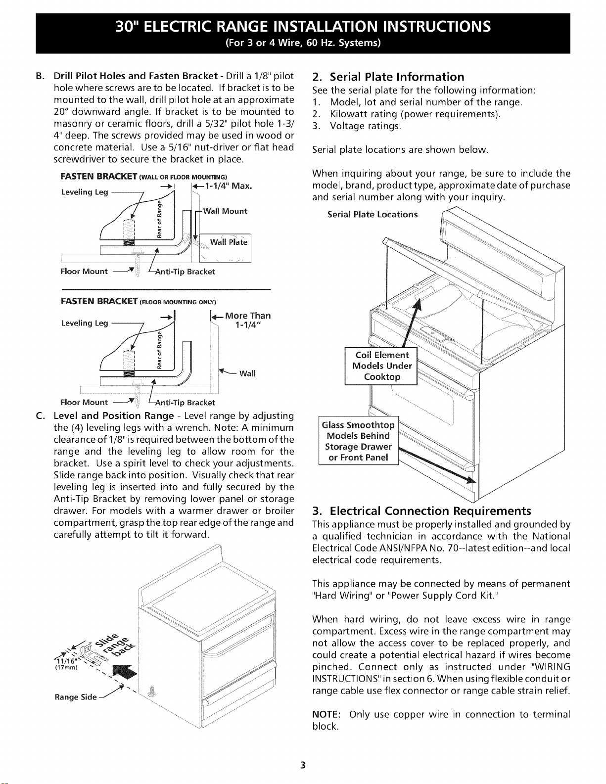
B.
Drill Pilot Holes and Fasten Bracket - Drill a 1/8" pilot
hole where screws are to be located. If bracket is to be
mounted to the wall, drill pilot hole at an approximate
20 ° downward angle. If bracket is to be mounted to
masonry or ceramic floors, drill a 5/32" pilot hole 1-3/
4" deep. The screws provided may be used in wood or
concrete material. Use a 5/16" nut-driver or flat head
screwdriver to secure the bracket in place.
FASTEN BRACKET (WALL OR FLOOR MOUNTING)
----_i 14--1=1/4" Max.
Leveling Leg -- b\
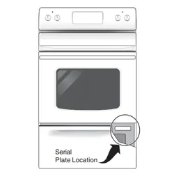
2. Serial Plate Information
See the serial plate for the following information:
1. Model, lot and serial number of the range.
2. Kilowatt rating (power requirements).
3. Voltage ratings.
Serial plate locations are shown below.
When inquiring about your range, be sure to include the
model, brand, product type, approximate date of purchase
and serial number along with your inquiry.
Serial Plate Locations
Floor Mount
C.
i iiii:i
Floor Mount
'ily
ip Bracket
Level and Position Range - Level range by adjusting
the (4) leveling legs with a wrench. Note: A minimum
clearance of 1/8" is required between the bottom of the
range and the leveling leg to allow room for the
bracket. Use a spirit level to check your adjustments.
Slide range back into position. Visually checkthat rear
leveling leg is inserted into and fully secured by the
Anti-Tip Bracket by removing lower panel or storage
drawer. For models with a warmer drawer or broiler
compartment, grasp the top rear edge of the range and
carefully attempt to tilt it forward.
Coil Element
Models Under
Cooktop
Glass Smoothtop _ "_
Models Behind
Storage Drawer __
or Front Panel
3. Electrical Connection Requirements
This appliance must be properly installed and grounded by
a qualified technician in accordance with the National
Electrical Code ANSI/NFPA No. 70--latest edition--and local
electrical code requirements.
This appliance may be connected by means of permanent
"Hard Wiring" or "Power Supply Cord Kit."
When hard wiring, do not leave excess wire in range
compartment. Excess wire in the range compartment may
not allow the access cover to be replaced properly, and
could create a potential electrical hazard if wires become
pinched. Connect only as instructed under "WIRING
INSTRUCTIONS" in section 6. When using flexible conduit or
range cable use flex connector or range cable strain relief.
NOTE: Only use copper wire in connection to terminal
block.
3A. Models with Factory Connected Power
Supply Cord
NOTE: Some models may be equipped with a factory
connected three (3) conductor power supply cord.
Mobile home installation or areas where local codes do not
permit grounding through neutral, a four (4) conductor
power supplycord kit rated at 125/250 volts minimum, and
marked for use with ranges shall be used. See Range
Connection Opening Size Chart for cord kit ampere rating
information. Terminals on end of wires must be either
closed loop or open-end spade lugs with upturned ends.
3B. Models Requiring Power Supply Cord Kit
RISK OF FIRE OR ELECTRICAL SHOCK MAY OCCUR IF AN
INCORRECT SIZE RANGE CORD KIT IS USED, THE
INSTALLATION INSTRUCTIONS ARE NOT FOLLOWED OR
STRAIN RELIEF BRACKET IS DISCARDED.
This appliance may be connected by means of a power
supply cord. Only a power supply cord kit rated at 125/250
volts minimum, and marked for use with ranges shall be
used. See chart on page 3 for cord kit ampere rating
information. Cord must have either three (3) or four (4)
conductors. Terminals on end of wires must be either
closed loop or open-end spade lugs with upturned ends.
Cord must have strain relief clamp.
See section 5Afor 3-wire or section 5B for 4-wire connection.
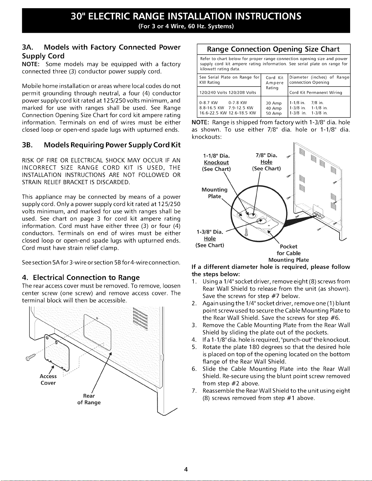
4. Electrical Connection to Range
The rear access cover must be removed. To remove, loosen
center screw (one screw) and remove access cover. The
terminal block will then be accessible.
/
/
Access I"-""
Cover /
Rear
of Range
Range Connection Opening Size Chart
Refer to chart below for proper range connection opening size and power
supply cord kit ampere rating information. See serial plate on range for
kilowatt rating data.
See Serial Plate on Range for
KW Rating
120/240 Volts 120/208 Volts
Cord Kit
Ampere
Rating
Diameter (inches) of Range
connection Opening
Cord Kit Permanent Wiring
0-8.7 KW 0-7.8 KW 30 Amp 1-1/8 in. 7/8 in.
8.8-16.5 KW 7.9-12.5 KW 40 Amp 1-3/8 in. 1-1/8 in.
16.6-22.5 KW 12.6-18.5 KW 50 Amp 1-3/8 in. 1-3/8 in.
NOTE: Range is shipped from factory with 1-3/8" dia. hole
as shown. To use either 7/8" dia. hole or 1-1/8" dia.
knockouts:
1-1/8" Dia. 7/8" Dia.
Knockout Hole
(See Chart) (See Chart)
Mounting
Plate
1=3/8" Dia.
Hole
(See Chart)
Pocket
for Cable
Mounting Plate
If a different diameter hole is required, please follow
the steps below:
1. Using a 1/4" socket driver, remove eight (8) screws from
Rear Wall Shield to release from the unit (as shown).
Save the screws for step #7 below.
2. Again using the 1/4" socket driver, remove one (1) blunt
point screw used to secure the Cable Mounting Plate to
the Rear Wall Shield. Save the screws for step #6.
3. Remove the Cable Mounting Plate from the Rear Wall
Shield by sliding the plate out of the pockets.
4. Ifa 1-1/8"dia. holeisrequired,"punch-out"theknockout.
5. Rotate the plate 180 degrees so that the desired hole
is placed on top of the opening located on the bottom
flange of the Rear Wall Shield.
6. Slide the Cable Mounting Plate into the Rear Wall
Shield. Re-secure using the blunt point screw removed
from step #2 above.
7. Reassemble the Rear Wall Shield to the unit using eight
(8) screws removed from step #1 above.
4
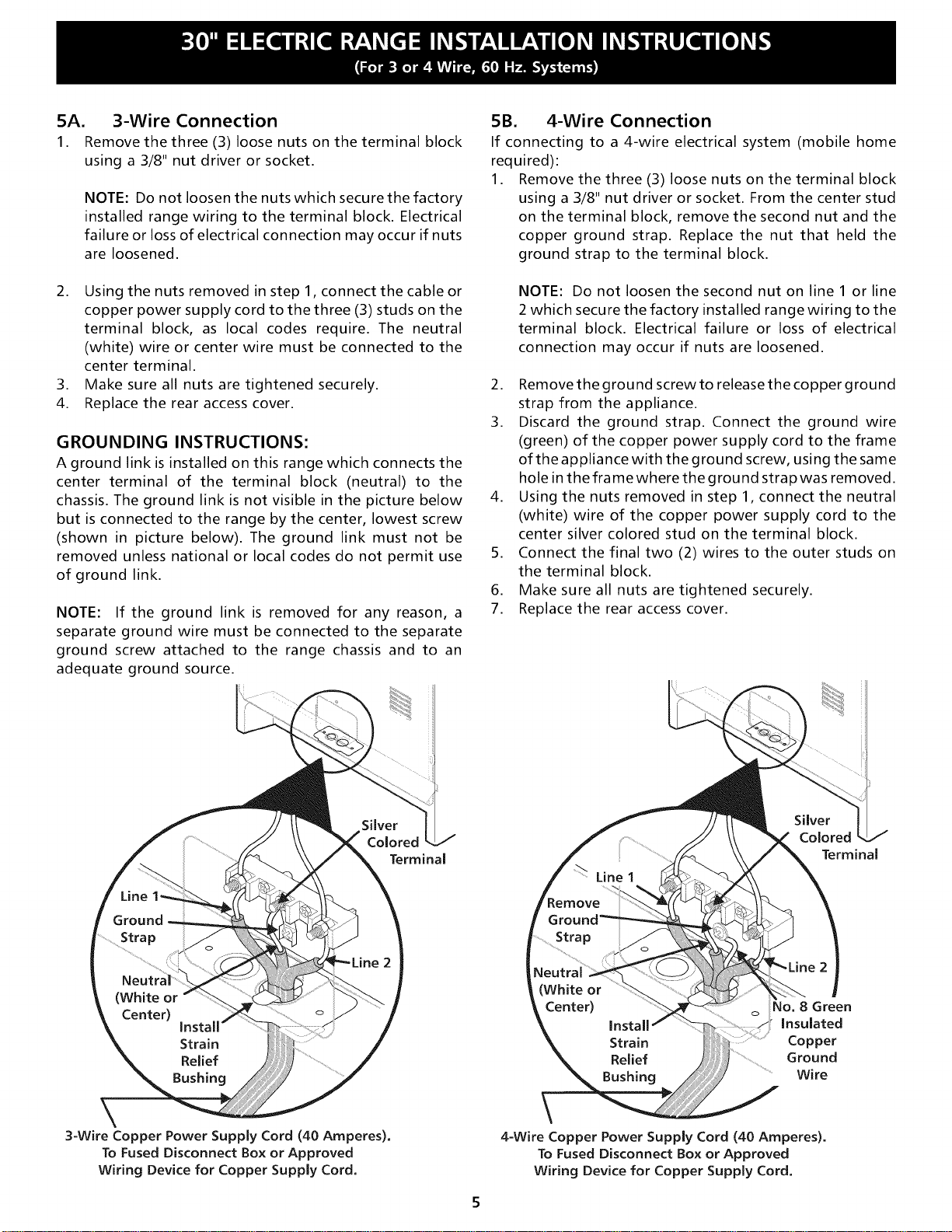
5A. 3-Wire Connection
1. Remove the three (3) loose nuts on the terminal block
using a 3/8" nut driver or socket.
NOTE: Do not loosen the nuts which secure the factory
installed range wiring to the terminal block. Electrical
failure or loss of electrical connection may occur if nuts
are loosened.
2. Using the nuts removed in step 1, connect the cable or
copper power supply cord to the three (3) studs on the
terminal block, as local codes require. The neutral
(white) wire or center wire must be connected to the
center terminal.
3. Make sure all nuts are tightened securely.
4. Replace the rear access cover.
GROUNDING INSTRUCTIONS:
A ground link is installed on this range which connects the
center terminal of the terminal block (neutral) to the
chassis. The ground link is not visible in the picture below
but is connected to the range by the center, lowest screw
(shown in picture below). The ground link must not be
removed unless national or local codes do not permit use
of ground link.
NOTE: If the ground link is removed for any reason, a
separate ground wire must be connected to the separate
ground screw attached to the range chassis and to an
adequate ground source.
5B. 4-Wire Connection
If connecting to a 4-wire electrical system (mobile home
required):
1. Remove the three (3) loose nuts on the terminal block
using a 3/8" nut driver or socket. From the center stud
on the terminal block, remove the second nut and the
copper ground strap. Replace the nut that held the
ground strap to the terminal block.
NOTE: Do not loosen the second nut on line1 or line
2 which secure the factory installed range wiring to the
terminal block. Electrical failure or loss of electrical
connection may occur if nuts are loosened.
2. Remove the ground screw to release the copper ground
strap from the appliance.
3. Discard the ground strap. Connect the ground wire
(green) of the copper power supply cord to the frame
of the appliance with the ground screw, using the same
hole in the frame where the ground strap was removed.
4. Using the nuts removed in step 1, connect the neutral
(white) wire of the copper power supply cord to the
center silver colored stud on the terminal block.
5. Connect the final two (2) wires to the outer studs on
the terminal block.
6. Make sure all nuts are tightened securely.
7. Replace the rear access cover.
\
3-Wire Copper Power Supply Cord (40 Amperes).
To Fused Disconnect Box or Approved
Wiring Device for Copper Supply Cord.
Terminal
Terminal
No. 8 Green
Insulated
Copper
Ground
Wire
4=Wire Copper Power Supply Cord (40 Amperes).
To Fused Disconnect Box or Approved
Wiring Device for Copper Supply Cord,
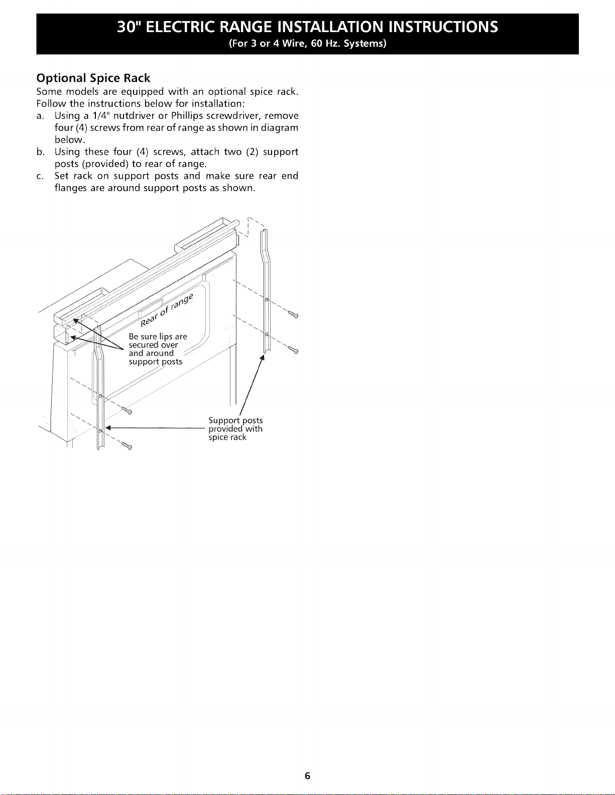
Optional Spice Rack
Some models are equipped with an optional spice rack.
Follow the instructions below for installation:
a. Using a 1/4" nutdriver or Phillips screwdriver, remove
four (4) screws from rear of range as shown in diagram
below.
b. Using these four (4) screws, attach two (2) support
posts (provided) to rear of range.
c. Set rack on support posts and make sure rear end
flanges are around support posts as shown.
/
Support posts
provided with
spice rack

LA INSTALACION Y EL SERVIClO DEBEN SER EFECTUADOS POR UN TECNICO CALIFICADO.
IMPORI"ANI"E: CONSERVE ESTAS INSTRUCClONES PARA USO DEL INSPECTOR LOCAL
DE ELECl"RIClDAD.
LEA Y CONSERVE ESTAS INSTRUCClONES PARA REFERENClA FUTURA.
1. Espacios Libres y Dimensiones
a. Provea espacios libres adecuados entre la estufa y las superficies combustibles adyacentes.
b. Ubicaci6n - Revise el lugar donde ser_ instalada la estufa. Verifique el suministro de energia electrica y la estabilidad del piso.
c. Es esencial que se usen las dimensiones que se muestran. Las dimensiones indicadas proveen los espacios libres minimos. La
superficie de contacto debe ser firme y nivelada.
VISTADE .............. , ............ ............] .............
FRENTE_ __ _
1',, 3o-*1
__ 30 . _
Minimo
MinJmo a la { Minimo a los
pared en cada
/
lado de la estufa 1 8" armarios en
cada lado de
sobre una altura l la estufa
de 36"
VISTA
LATERAL
Profundidad ÷I 3"÷I
m_xima de Os -
armarios sobre
la cubierta de
la estufa.
30" _ Espacio libre de 0" debajo de la cubierta y en la parte
trasera de la estufa,
t
48 I/2"
Con un
Especiero
Opcional
1
47 3/4"
Maximo
/
\
44 3/8"
Puerta abierta
I_--- 29 7/8" ___ 3/8"
' k ...............
\ \
\ \
Linea central
de la estufa
q_
i
3_i12,,_-_.... _
de
pared
El _rea del cubo de linea de puntos
muestra donde se debe instalar el
tomacorriente el_ctrico para
instalad6n a ras de la pared.
Todas las dimensiones para la
ubicaci6n del tomacorriente
el_ctrico son m_ximas.
* 30" ESPACIO LIBRE MINIMO ENTRE LA CUBIERTA DE COCINAR DE LA ESTUFA Y LA PARTE INFERIOR DE UN ARMARIO DE METAL O
DE MADERA NO PROTEGIDO; O 24" MINIMO CUANDO LA PARTE INFERIOR DE UN ARMARIO DE METAL O DE MADERA ESTA PROTEGIDA
CON CARTON RETARDANTE A LAS LLAMAS DE NO MENOS DE 1/4" CUBIERTO CON CHAPA DE ACERO NO INFERIOR AL # 28 MSG, ACERO
INOXIDABLE DE 0,015", ALUMINIO DE 0,024 O COBRE DE 0,020". ELESPACIOLIBREDE0"ESELMINIMOPARALAPARTETRASERADE
LA ESTUFA. SlGATODAS LAS DIMENSlONES INDICADAS ANTERIORMENTE PARA EVlTAR DANOS MATERIALES, RIESGOS DE INCENDIO
Y CORTES INCORRECTOS DE LOS ARMARIOS Y DE LAS MESADAS.
PARA ELIMINAR EL RIESGO DE QUEMADURAS E INCENDIOS AL TOCAR SUPERFICIES SOBRECALENTADAS, SE DEBE EVlTAR
COLOCAR ESPAClO PARA ARMARIOS DE ALMACENAMIENTO SOBRE LAS ESTUFAS CON ELEMENTOS AL DESCUBIERTO. Sl SE
INSTALAN ARMARIOS SOBRE LA ESTUFA, SE PUEDEN REDUClR TALES RIESGOS INSTALANDO UNA CAMPANA PURIFICADORA QUE
SE PROYECTA HORIZONTALMENTE UN MINIMO DE 5" MAS AFUERA DE LA PARTE INFERIOR DE LOS ARMARIOS.
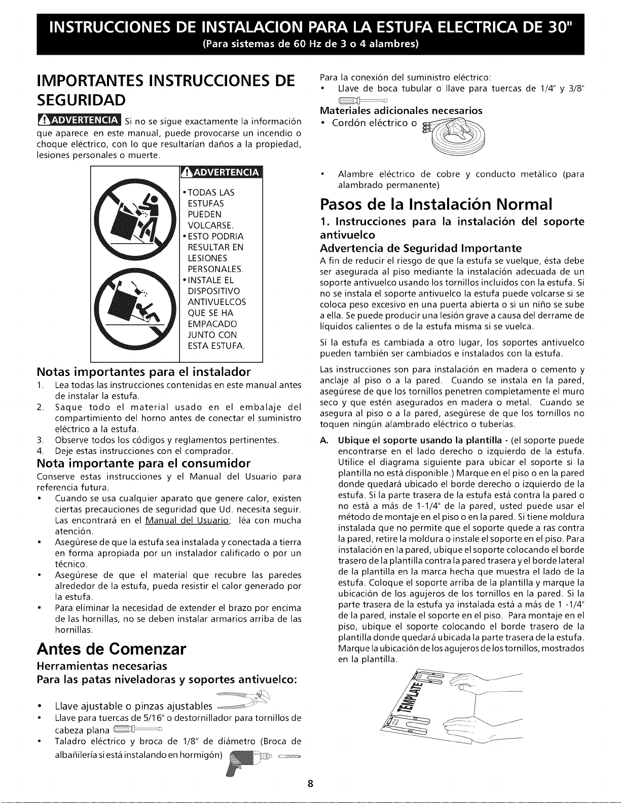
IIVlPORTANTES INSTRUCCIONES DE
SEGURIDAD
Si no se sigue exactamente la informacion
que aparece en este manual, puede provocarse un incendio o
choque electrico, con Io que resultar[an dahos a la propiedad,
lesiones personales o muerte.
• TODAS LAS
ESTUFAS
PUEDEN
VOLCARSE.
• ESTO PODRIA
RESULTAR EN
LESlONES
PERSONALES.
• INSTALE EL
DISPOSlTIVO
ANTIVUELCOS
QUE SE HA
EMPACADO
JUNTO CON
ESTA ESTUFA.
Notas importantes para el instalador
1. Lea todas las instrucciones contenidas en este manual antes
de instalar la estufa.
2. Saque todo el material usado en el embalaje del
compartimiento del horno antes de conectar el suministro
electrico a la estufa.
3. Observe todos los codigos y reglamentos pertinentes.
4. Deje estas instrucciones con el comprador.
Nota importante para el consumidor
Conserve estas instrucciones y el Manual del Usuario para
referencia futura.
• Cuando se usa cualquier aparato que genere calor, existen
ciertas precauciones de seguridad que Ud. necesita seguir.
Las encontrar_ en el Manual del Usuario.; lea con mucha
atencion.
• Aseg0rese de que la estufa sea instalada y conectada atierra
en forma apropiada por un instalador calificado o por un
tecnico.
• Aseg0rese de que el material que recubre las paredes
alrededor de la estufa, pueda resistir el calor generado por
la estufa.
• Para eliminar la necesidad de extender el brazo por encima
de las hornillas, no se deben instalar armarios arriba de las
hornillas.
Antes de Comenzar
Herramientas necesarias
Para las patas niveladoras y soportes antivuelco:
• Llave ajustable o pinzas ajustables ,_-:_-=_....
• Llave para tuercas de 5/1 6" o destornillador para tornillos de
cabeza plana
• Taladro electrico y broca de 1/8" de di_metro (Broca de
albahiler[a siest_ instalando en hormig6n)
Para la conexion del suministro electrico:
• Llave de boca tubular o Ilave para tuercas de 1/4" y 3/8"
]
Materiales adicionales necesarios
• Cordon electrico o
• Alambre electrico de cobre y conducto met_lico (para
alambrado permanente)
Pasos de la Instalacion Normal
1. Instrucciones para la instalacion del soporte
antivuelco
Advertencia de Seguridad Importante
A fin de reducir el riesgo de que la estufa se vuelque, esta debe
ser asegurada al piso mediante la instalacion adecuada de un
soporte antivuelco usando los tornillos incluidos con la estufa. Si
no se instala el soporte antivuelco la estufa puede volcarse si se
coloca peso excesivo en una puerta abierta o si un nifio se sube
a ella. Sepuede producir una lesi6n grave a causa del derrame de
liquidos calientes o de la estufa misma si se vuelca.
Si la estufa es cambiada a otro lugar, los soportes antivuelco
pueden tambien ser cambiados e instalados con la estufa.
Las instrucciones son para instalaci6n en madera o cemento y
anclaje al piso o a la pared. Cuando se instala en la pared,
asegOrese de que los tornillos penetren completamente el muro
seco y que esten asegurados en madera o metal. Cuando se
asegura al piso o a la pared, aseg0rese de que los tornillos no
toquen ningOn alambrado electrico o tuberias.
A. Ubique el soporte usando la plantilla - (el soporte puede
encontrarse en el lado derecho o izquierdo de la estufa.
Utilice el diagrama siguiente para ubicar el soporte si la
plantilla no est_ disponible.) Marque en el piso o en la pared
donde quedar_ ubicado el borde derecho o izquierdo de la
estufa. Si la parte trasera de la estufa est_ contra la pared o
no est_ a m_s de 1-1/4" de la pared, usted puede usar el
metodo de montaje en el piso o en la pared. Si tiene moldura
instalada que no permite que el soporte quede a ras contra
la pared, retire la moldura o instale el soporte en el piso. Para
instalacion en la pared, ubique el soporte colocando el borde
trasero de la plantilla contra la pared trasera yel borde lateral
de la plantilla en la marca hecha que muestra el lado de la
estufa. Coloque el soporte arriba de la plantilla y marque la
ubicacion de los agujeros de los tornillos en la pared. Si la
parte trasera de la estufa ya instalada est_ a m_s de 1 -1/4"
de la pared, instale el soporte en el piso. Para montaje en el
piso, ubique el soporte colocando el borde trasero de la
plantilla donde quedar_ ubicada la parte trasera de la estufa.
Marque la ubicaci6n de los agujeros de los tornillos, mostrados
en la plantilla.
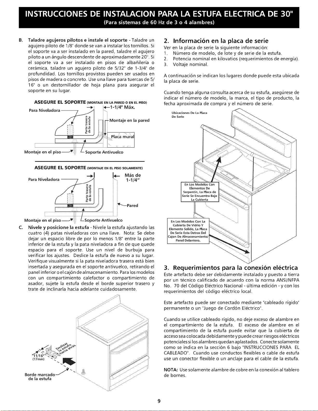
B.
Taladre agujeros pilotos e instale el soporte - Taladre un
agujero piloto de 1/8" donde se van a instalar los tornillos. Si
el soporte va a ser instalado en la pared, taladre el agujero
piloto a un _ngulo descendente de aproximadamente 20°. Si
el soporte va a ser instalado en pisos de albahileria o
cer_mica, taladre un agujero piloto de 5/32" de 1-3/4" de
profundidad. Los tornillos provistos pueden ser usados en
pisos de madera o concreto. Use una Ilave para tuercas de 5/
16" o un destornillador de hoja plana para asegurar el
soporte en su lugar.
ASEGURE EL SOPORTE (MONTAJEE__ PARED0 ENELPIISO)
-=_1 1_-=1=1/4 " M_x,
Para Niveladora-
-Montaje en la pared
2. Informacion en la placa de serie
Ver en la placa de serie la siguiente informacion:
1. N5mero de modelo, de Iote y de serie de la estufa.
2. Potencia nominal en kilovatios (requerimientos de energia).
3. Voltaje nominal.
A continuacion se indican los lugares donde puede esta ubicada
la placa de serie.
Cuando tenga alguna consulta acerca de su estufa, asegOrese de
indicar el nOmero de modelo, la marca, el tipo de producto, la
fecha aproximada de compra y el nOmero de serie.
Ubicaciones De La Placa
De Serie
I iiii
i!i
Montaje en el piso
'laca mura
,porte Antivuelco
C.
ASEGURE EL SOPORTE (MONTAJE EN EL P|SO SOLAIVlENTE)
Para Niveladora -- _ 1=1/4"
i Pared
Montaje en el piso_' -Soporte Antivuelco
Nivele y posicione la estufa - Nivele la estufa ajustando las
cuatro (4) patas niveladoras con una Ilave. Nota: Se debe
dejar un espacio libre de por Io menos 1/8" entre la parte
inferior de la estufa y la pata niveladora a fin de que quede
espacio para el soporte. Use un nivel de burbuja para
verificar los ajustes. Deslice la estufa de nuevo a su lugar.
Verifique visualmente si la pata niveladora trasera est_ bien
insertada y asegurada en el soporte antivuelco, retirando el
panel inferior o el cajon de almacenamiento. Para los modelos
con un compartimiento calefactor o compartimiento de
asador, sujete la estufa desde el borde superior trasero y
trate de inclinarla hacia adelante cuidadosamente.
En Los Modelos Con
Elementos De
Serpentin, La Plata de
Serie Se Encuentra Bajo
La Cubierta
L
',,
En Los Modelos Con La _ _'_..
Cubierta De Vidrio Y _\_.
Elemento Solido, La Plata I _\ "_._
De Serie Esta Detras Del L _-_-.
Panel Delantero, k. _ _ "<
3. Requerimientos para la conexion electrica
Este artefacto debe ser debidamente instalado y puesto a tierra
por un tecnico calificado de acuerdo con la norma ANSI/NFPA
No. 70 del C6digo Electrico Nacional- Oltima edici6n - y con los
requerimientos del c6digo electrico local.
Este artefacto puede ser conectado mediante "cableado r[gido"
permanente o un "Juego de Cord6n Electrico".
Cuando se utilice cableado r[gido, no deje exceso de alambre en
el compartimiento de la estufa. El exceso de alambre en el
compartimiento de la estufa puede evitar que la cubierta de
acceso sea colocada debidamente y puede crear riesgos electricos
potenciales si los alambres quedan aplastados. Conecte solamente
como se indica en la secci6n 6 bajo "INSTRUCCIONES PARA EL
CABLEADO". Cuando use conductos flexibles o cable de estufa
use un conector flexible o un anclaje para el cable de la estufa.
NOTA: Use solamente alambre de cobre en la conexi6n al tablero
de bornes.
3A. Modelos con el cordon electrico
conectado en la fabrica
NOTA: Algunos modelos vienen equipados con cord6n electrico
de tres (3) conductores conectado en la f_brica.
La instalaci6n en casas moviles o _reas donde los c6digos locales
no permiten puesta a tierra a traves del conductor neutro, se debe
usar un juego de cordon electrico de cuatro (4) conductores para
125/250 voltios minimo y marcado para uso con estufas. Consulte
la Tabla de tamaho de la abertura de conexion de la estufa para
la informacion sobre los amperes del juego de cord6n. Los bornes
en los extremos de los alambres deben ser de anillo cerrado u
horquillas abiertas con extremos dirigidos hacia arriba.
3B. Modelos que requieren el juego de
cordon electrico
PUEDE OCURRIR RIESGO DE INCENDIO O CHOQUE ELECTRICO Sl
SE USA UN JUEGO DE CORDON DE ESTUFA DE TAMANO
INCORRECTO, Sl LAS INSTRUCCIONES DE INSTALACION NO SON
SEGUIDAS O Sl NO SE USA EL ANCLAJE DEL CABLE.
Este artefacto puede ser conectado mediante u n cordon electrico.
Se usar_ solamente un juego de cord6n electrico para 125/250
voltios como m[nimo y marcado para uso con estufas. Consulte
la tabla para la informacion sobre los amperes del juego de
cordon. El cordon debe tener tres (3) o cuatro (4) conductores.
Los bornes en los extremos de los alambres deben ser de anillo
cerrado o de horquillas abiertas con extremos dirigidos hacia
arriba. El cord6n debe tener una grapa de anclaje.
VEA SECClON 5A PARA CONEXION DE 3ALAMBRES ORSECClON
5B PARA CONEXION DE 4 ALAMBRES
4. Conexion electrica a la estufa
Se debe sacar la tapa de acceso trasera. Para sacar afloje el
tornillo central (un tornillo) ysaque la tapa de acceso. El tablero
de bornes quedara entonces accesible.
Parte Trasera
De La Estufa
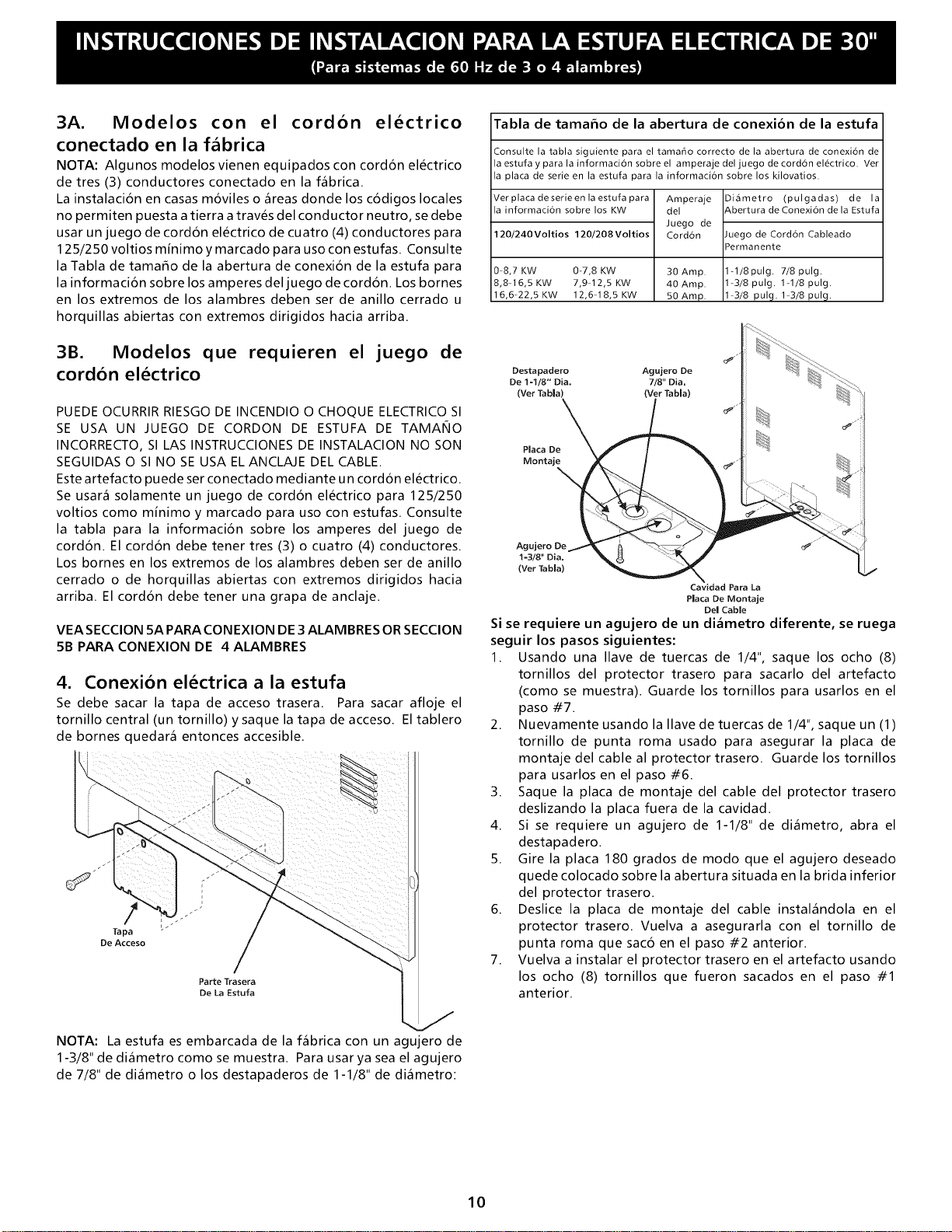
Tabla de tamaEo de la abertura de conexion de la estufa
Consulte la tabla siguiente para el tama_o correcto de la abertura de conexion de
la estufa y para la information sobre el amperaje del juego de cord6n el_ctrico. Ver
la plata de serie en la estufa para la information sobre los kilovatios.
Ver plata de serie en la estufa para
la information sobre los KW
120/240 Voltios 120/208 Voltios
0 8,7 KW 0-7,8 KW 30 Amp.
8,8 16,5 KW 7,9 12,5 KW 40 Amp.
16,6 22,5 KW 12,6 18,5 KW 50 Amp.
Amperaje
del
Juego de
Cordbn
Diametro (pulgadas) de la
&bertura de Conexion de la Estufa
luego de Cordbn Cableado
Permanente
1-1/8pulg. 7/8pulg.
1-3/8 pulg. 1-1/8 pulg.
1 3/8 pul 9. 1 3/8 pul 9.
Destapadero
De 1-1/8" Dia.
(Vet Tabla)
(Vet Tabla)
Agujero De
7/8 _ Dia.
(Vet Tabla)
Cavidad Para La
Placa De Montaje
Del Cable
Si se requiere un agujero de un di_metro diferente, se ruega
seguir los pasos siguientes:
1. Usando una Ilave de tuercas de 1/4", saque los ocho (8)
tornillos del protector trasero para sacarlo del artefacto
(como se muestra). Guarde los tornillos para usarlos en el
paso #7.
2. Nuevamente usando la Ilave de tuercas de 1/4", saque un (1)
tornillo de punta roma usado para asegurar la placa de
montaje del cable al protector trasero. Guarde los tornillos
para usarlos en el paso #6.
3. Saque la placa de montaje del cable del protector trasero
deslizando la placa fuera de la cavidad.
4. Si se requiere un agujero de 1-1/8" de di_metro, abra el
destapadero.
5. Gire la placa 180 grados de modo que el agujero deseado
quede colocado sobre la abertura situada en la brida inferior
del protector trasero.
6. Deslice la placa de montaje del cable instal_ndola en el
protector trasero. Vuelva a asegurarla con el tornillo de
punta roma que saco en el paso #2 anterior.
7. Vuelva a instalar el protector trasero en el artefacto usando
los ocho (8) tornillos que fueron sacados en el paso #1
anterior.
NOTA: La estufa es embarcada de la f_brica con un agujero de
1-3/8" de di_metro como se muestra. Para usar ya sea el agujero
de 7/8" de di_metro o los destapaderos de 1-1/8" de di_metro:
10
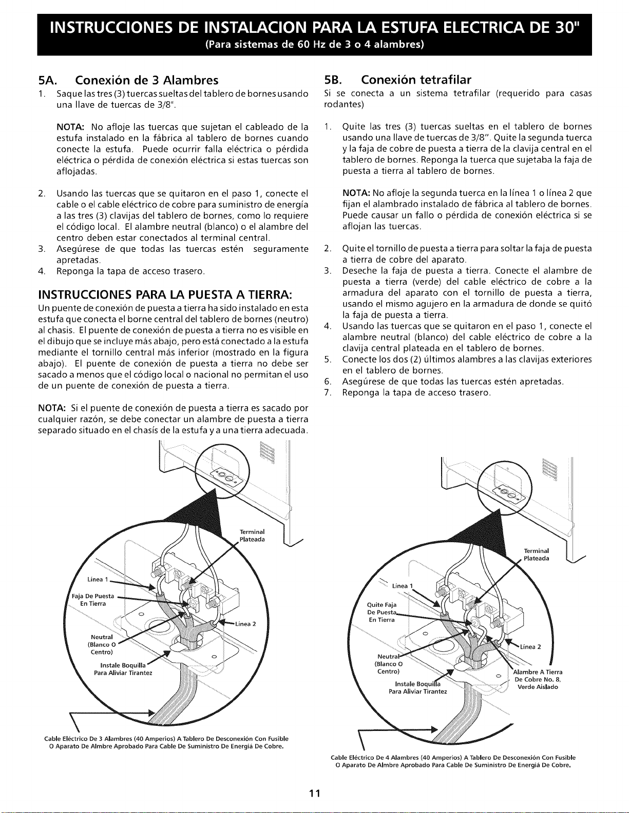
5A. Conexion de 3 Alambres
1. Saque las tres (3) tuercas sueltas del tablero de bornes usando
una Ilave de tuercas de 3/8".
NOTA: No afloje las tuercas que sujetan el cableado de la
estufa instalado en la f_brica al tablero de bornes cuando
conecte la estufa. Puede ocurrir falla electrica o perdida
electrica o perdida de conexi6n electrica siestas tuercas son
aflojadas.
2. Usando las tuercas que se quitaron en el paso 1, conecte el
cable o el cable electrico de cobre para suministro de energia
a las tres (3) clavijas del tablero de bornes, como Io requiere
elc6digolocal. Elalambreneutral(blanco) oelalambredel
centro deben estar conectados al terminal central.
3. AsegOrese de que todas las tuercas esten seguramente
apretadas.
4. Reponga la tapa de acceso trasero.
INSTRUCClONES PARA LA PUESTA A TIERRA:
Un puente de conexion de puesta a tierra ha sido instalado en esta
estufa que conecta el borne central del tablero de bornes (neutro)
al chasis. El puente de conexion de puesta a tierra no es visible en
el dibujo que se incluye m_s abajo, pero est_ conectado a la estufa
mediante el tornillo central m_s inferior (mostrado en la figura
abajo). El puente de conexi6n de puesta a tierra no debe ser
sacado a menos que el codigo local o nacional no permitan el uso
de un puente de conexi6n de puesta a tierra.
NOTA: Si el puente de conexi6n de puesta a tierra es sacado por
cualquier raz6n, se debe conectar un alambre de puesta a tierra
separado situado en el chasis de la estufa ya una tierra adecuada.
5B. Conexion tetrafilar
Si se conecta a un sistema tetrafilar (requerido para casas
rodantes)
1.
Quite las tres (3) tuercas sueltas en el tablero de bornes
usando una Ilave de tuercas de 3/8". Quite la segunda tuerca
y la faja de cobre de puesta a tierra de la clavija central en el
tablero de bornes. Reponga la tuerca que sujetaba la faja de
puesta a tierra al tablero de bornes.
NOTA: No afloje la segunda tuerca en la Ifnea 1 o Ifnea 2 que
fijan el alambrado instalado de f_brica al tablero de bornes.
Puede causar un fallo o perdida de conexi6n electrica si se
aflojan las tuercas.
2. Quite eltornillode puesta a tierra para soltarla faja de puesta
a tierra de cobre del aparato.
3. Deseche la faja de puesta a tierra. Conecte el alambre de
puesta a tierra (verde) del cable electrico de cobre a la
armadura del aparato con el tornillo de puesta a tierra,
usando el mismo agujero en la armadura de donde se quit6
la faja de puesta a tierra.
4. Usando las tuercas que se quitaron en el paso 1, conecte el
alambre neutral (blanco) del cable electrico de cobre a la
clavija central plateada en el tablero de bornes.
5. Conecte los dos (2) Oltimos alambres alas clavijas exteriores
en el tablero de bornes.
6. AsegOrese de que todas las tuercas esten apretadas.
7. Reponga la tapa de acceso trasero.
\
Cable El&ctrico De 3 Alambres (40 Amperios) A Tablero De Desconexi6n Con Fusible
0 Aparato De Almbre Aprobado Para Cable De Suministro De Energi_ De Cobre.
De Cobre No. 8,
Verde Aislado
Cable El_ctrico De 4 Alambres (40 Amperios) A Tablero De Desconexi6n Con Fusible
0 Aparato De Alrnbre Aprobado Para Cable De Suministro De Energi_ De Cobre.
11
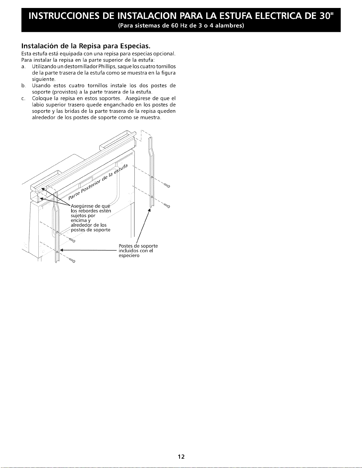
Instalacion de la Repisa para Especias.
Esta estufa est_ equipada con una repisa para especias opcional.
Para instalar la repisa en la parte superior de la estufa:
a. Utilizando un destornillador Phillips, saque los cuatro tornillos
de la parte trasera de la estufa como se muestra en la figura
siguiente.
b. Usando estos cuatro tornillos instale los dos postes de
soporte (provistos) a la parte trasera de la estufa.
c. Coloque la repisa en estos soportes. Aseg6rese de que el
labio superior trasero quede enganchado en los postes de
soporte y las bridas de la parte trasera de la repisa queden
alrededor de los postes de soporte como se muestra.
sujetos por ..........
encima y
alrededor de los
soporte
/
Postes de soporte
incluidos con el
especiero
12