1
Lowes.com/harborbreeze
Serial Number _________________________ Purchase Date _________________________
ATTACH YOUR RECEIPT HERE
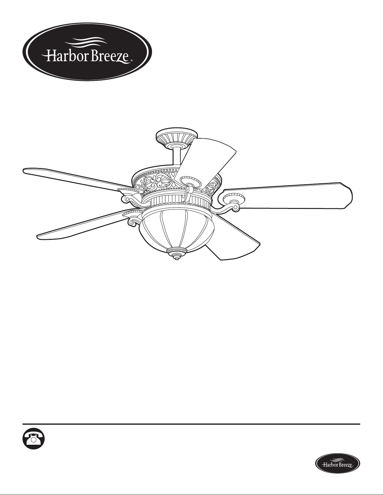
EB13356
ITEM #0464470
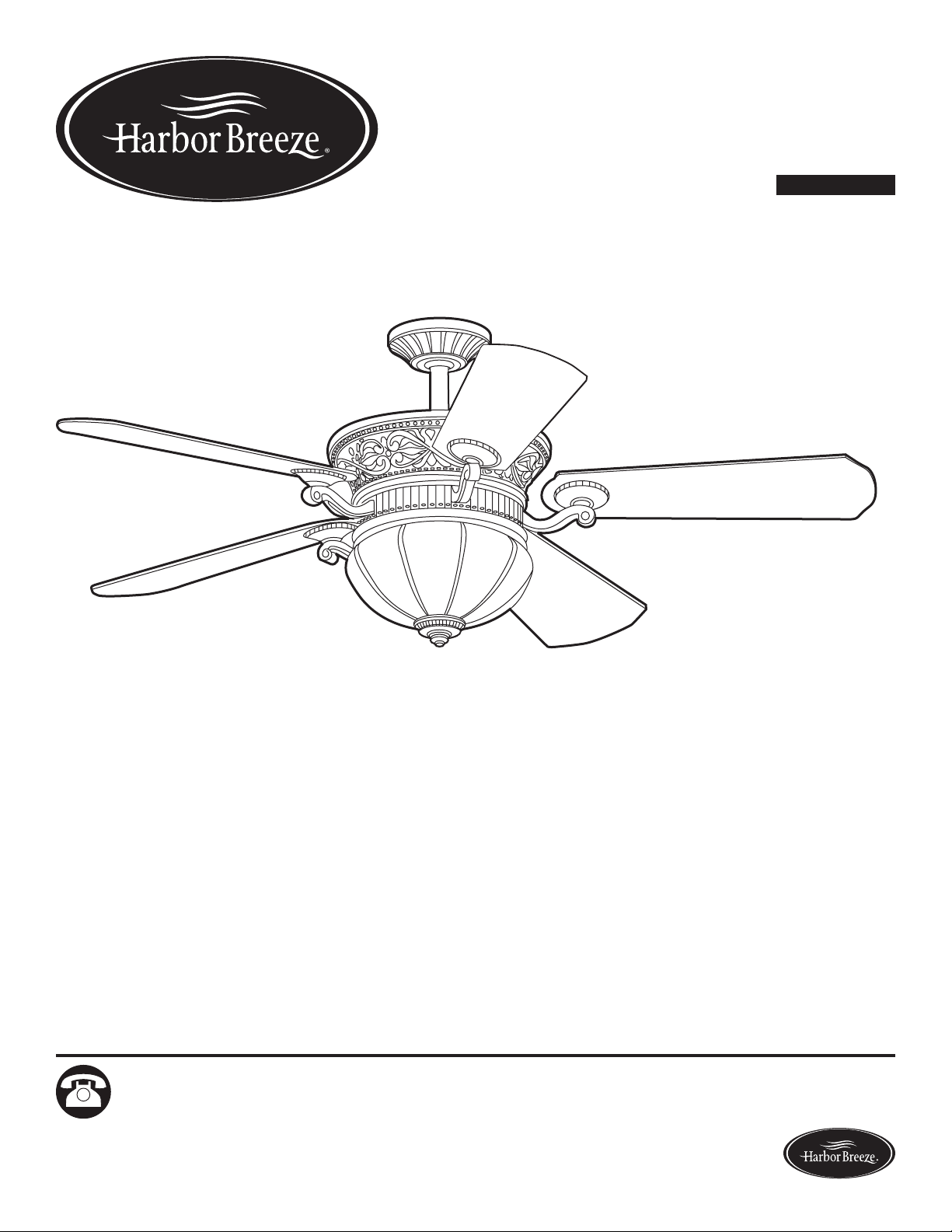
WAKEFIELD CEILING FAN
MODEL #40105
Español p. 23
1
Questions, problems, missing parts? Before returning to your retailer, call our customer
service department at 1-800-643-0067, 8 a.m. - 6 p.m., EST, Monday - Thursday, 8 a.m. - 5 p.m.,
EST, Friday.
Harbor Breeze® is a registered trademark
of LF, LLC. All Rights Reserved.

2
Lowes.com/harborbreeze
TABLE OF CONTENTS
Package Contents .................................................................3
Hardware Contents ................................................................4
Safety Information .................................................................5
Preparation ......................................................................6
Assembly Instructions ..............................................................7
Operating Instructions .............................................................17
Care and Maintenance ............................................................18
Troubleshooting ..................................................................18
Limited Lifetime Warranty ..........................................................21
Replacement Parts List ............................................................22
3
Lowes.com/harborbreeze
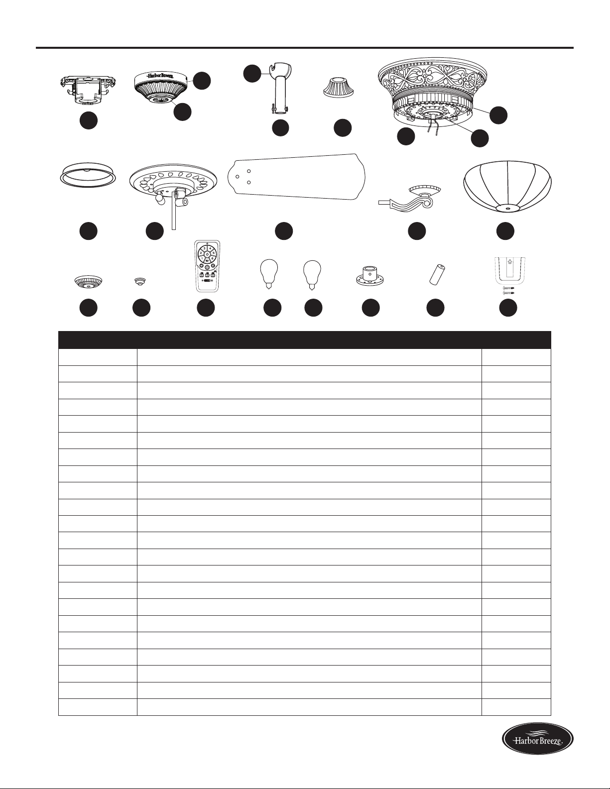
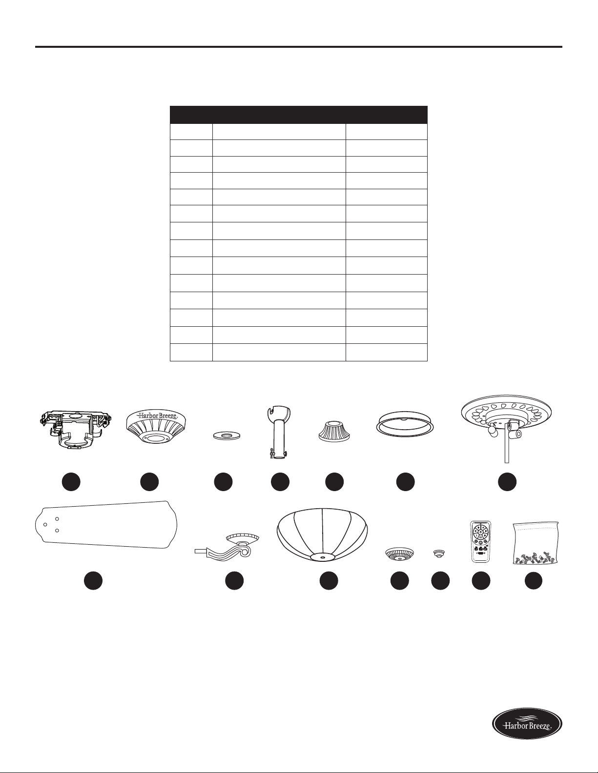
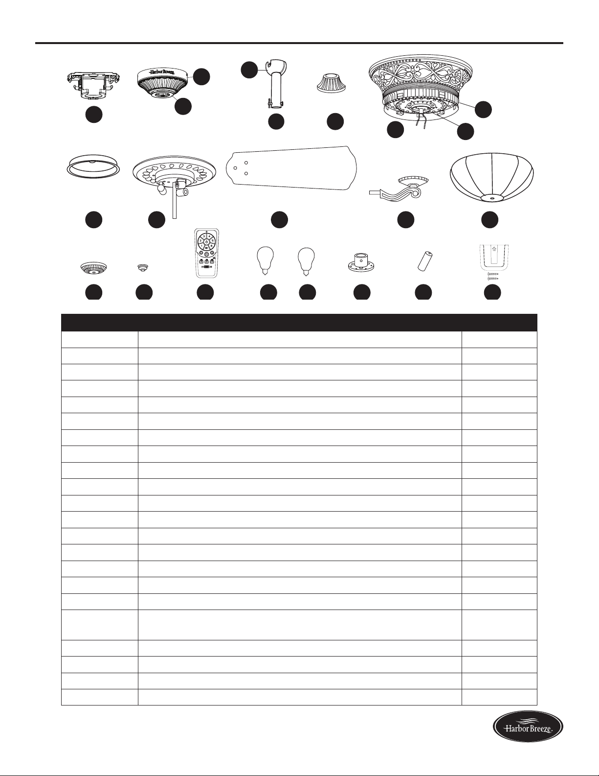
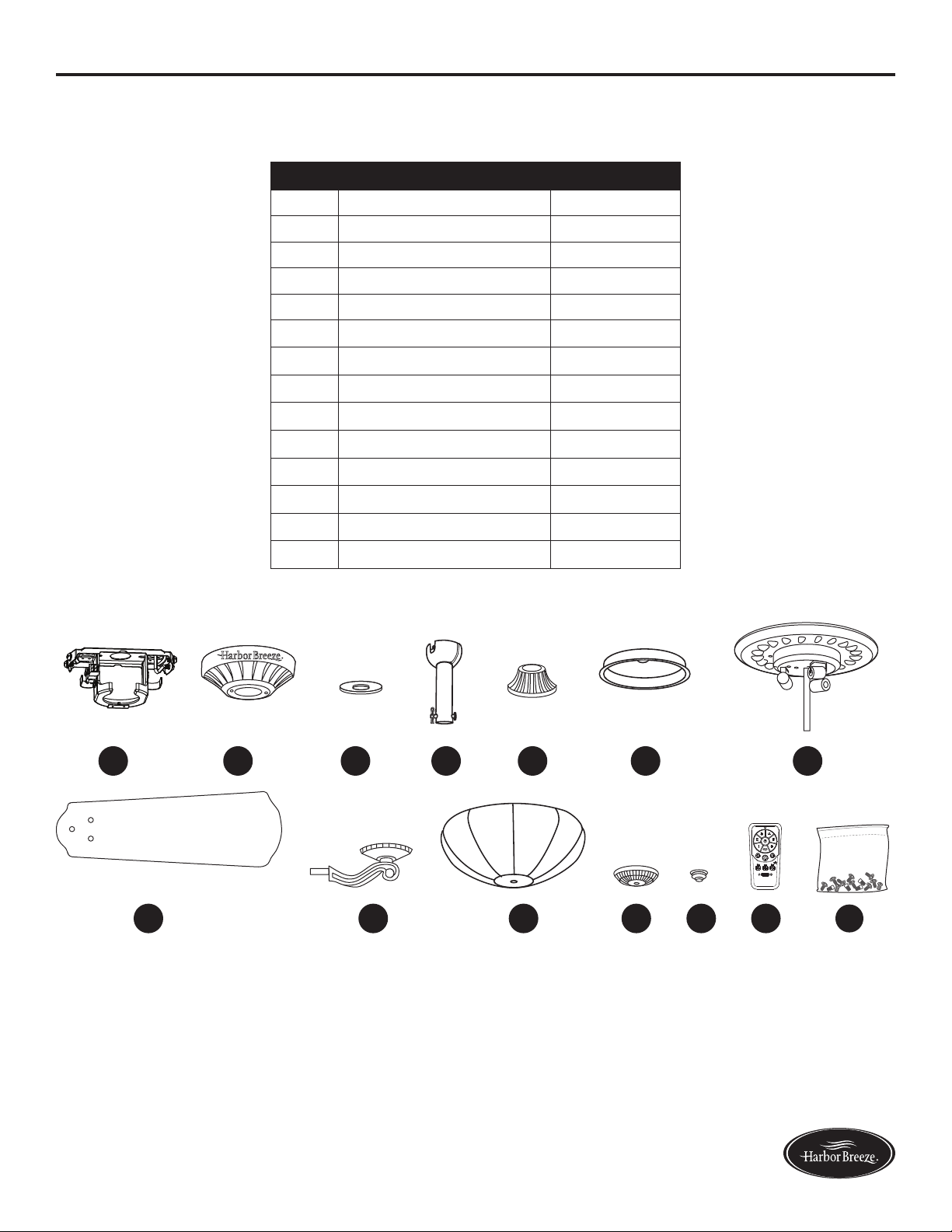
PACKAGE CONTENTS
A
A
A
B
A
C
A
D
A
O
A
GA
H
A
LA
M P Q S U V
A
N
A
I
A
JA
K
A
E
A
F
R
T
2
+
+
H
PART DESCRIPTION QUANTITY
A Mounting Bracket 1
B Canopy (preassembled to Mounting Bracket (A)) 1
C Canopy Cover (preassembled to Canopy (B)) 1
D Downrod 1
E Yoke Cover 1
F Motor Housing 1
G Switch Housing 1
H Light Kit 1
I Blade 5
J Blade Arm 5
K Glass Bowl 1
L Finial Cap 1
M Finial 1
N Remote Control 1
O Hanger Ball (preassembled to Downrod (D)) 1
P 25-watt Bulb 3
Q 40-watt Bulb 3
R Fitter Plate (preassembled to Motor Housing (F)) 1
S Coupling (preassembled to Motor Housing (F)) 1
T Flywheel (preassembled to Motor Housing (F)) 1
U Battery 1
V Wall Bracket Assembly 1
4
Lowes.com/harborbreeze
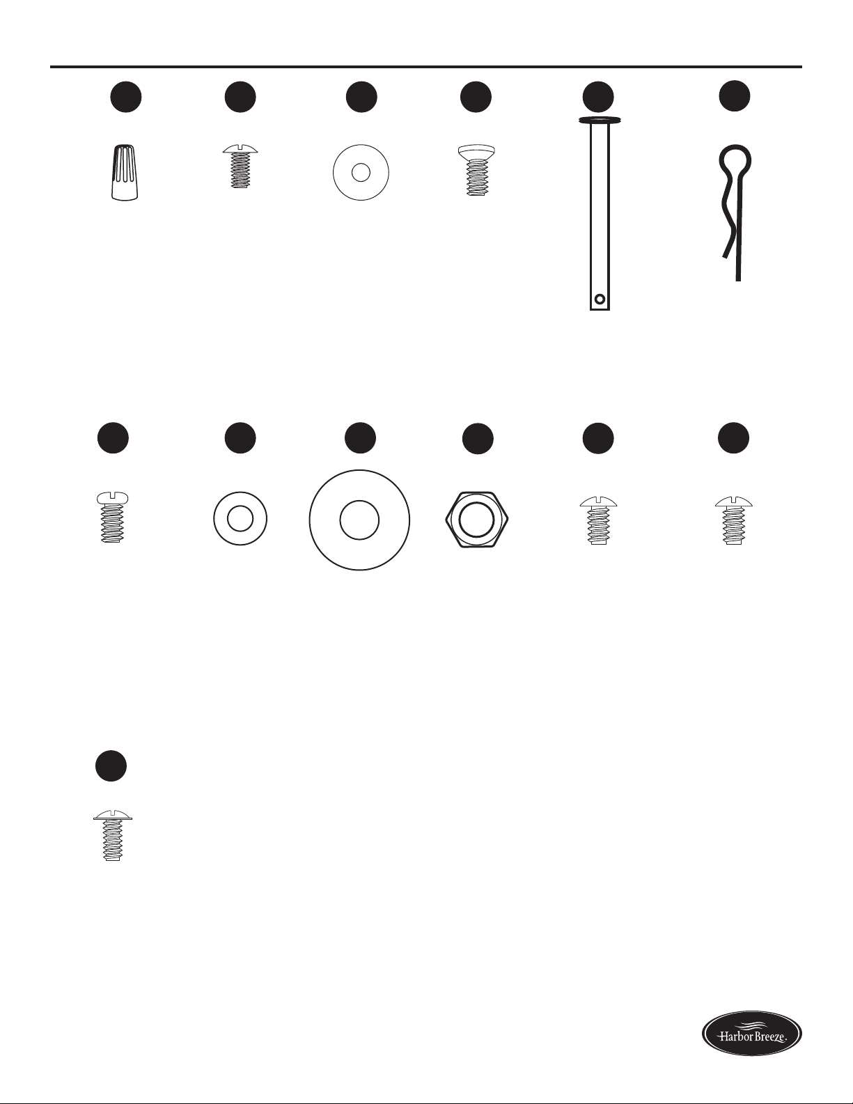
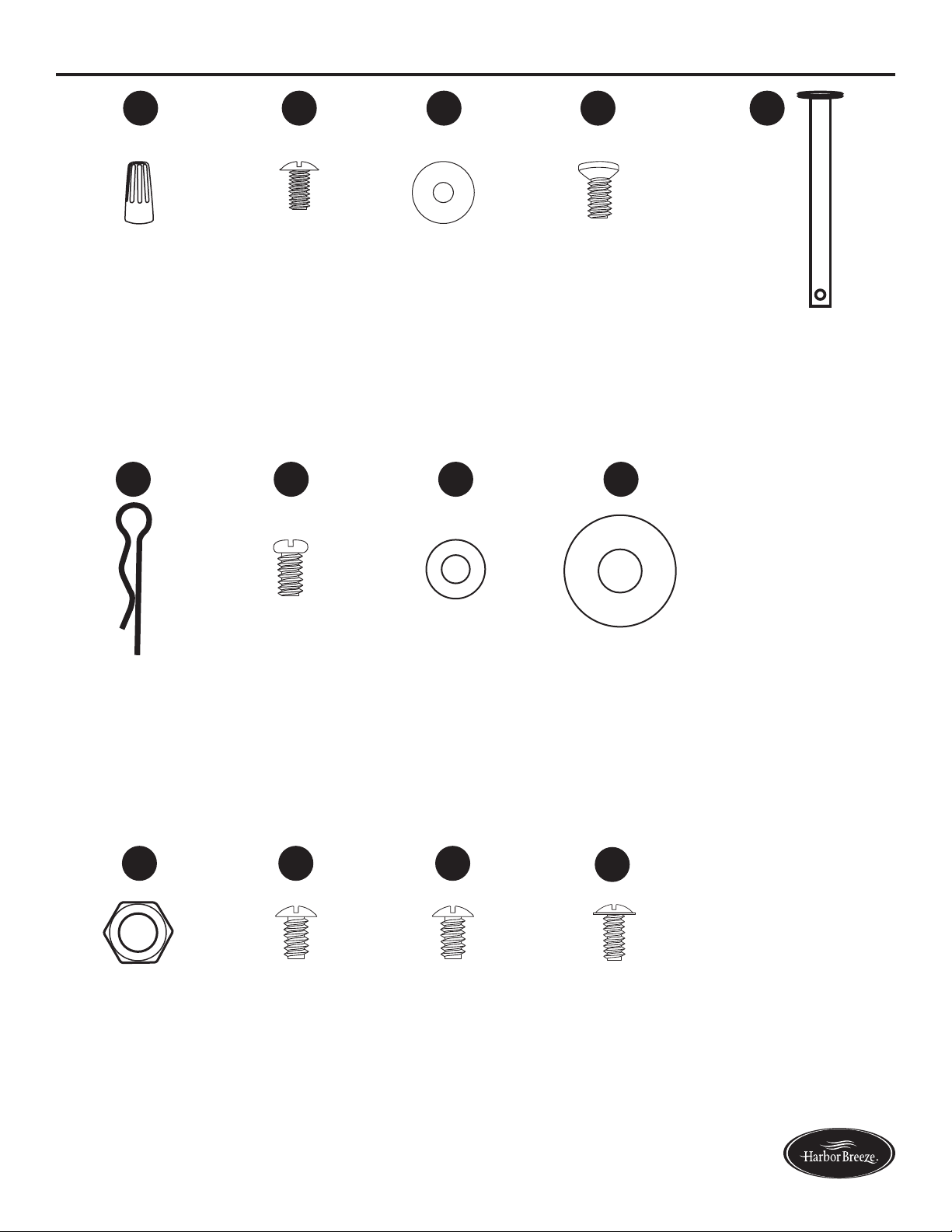
HARDWARE CONTENTS
Wire Connector
Qty. 3 + 1 extra
Blade Screw
Qty. 15 +
1 extra
Blade Washer
Qty. 15 +
1 extra
Motor Screw
Qty. 10 +
1 extra
Downrod Pin
Qty. 1
(preassembled
to Downrod
(D))
Downrod Clip
Qty. 1
(preassembled to
Downrod (D))
Motor Housing
Set Screw
Qty. 2
(preassembled
to Coupling
(S))
Flat Washer
Qty. 1
Rubber
Washer
Qty. 1
Hex Nut
Qty. 1
Mounting
Bracket Screw
Qty. 4
(preassembled
to Mounting
Bracket (A))
Switch Housing
Plate Screw
Qty. 3
(preassembled to
Fitter Plate (R))
Switch Housing
Screw
Qty. 3
(preassembled
to Switch
Housing (G))
AA BB CC DD EE
FF
HH
GG
MM
II
JJ
KK
LL
5
Lowes.com/harborbreeze
SAFETY INFORMATION
Please read and understand this entire manual before attempting to assemble, operate, or install the
product.
• Before you begin installing the fan, disconnect the power by removing fuses or turning off the
circuit breakers.
• Make sure that all electrical connections comply with local codes, ordinances, the National
ElectricalCodeandANSI/NFPA70-199.Hireaqualiedelectricianorconsultado-it-yourself
wiring handbook if you are unfamiliar with installing electrical wiring.
• Make sure the installation site you choose allows a minimum clearance of 7 ft. from the blades to
theoorandatleast30in.fromtheendofthebladestoanyobstruction.
• The net weight of this fan is: 24.73 lbs.
DANGER: When using an existing outlet box, make sure the outlet box is securely attached to
the building structure and can support the full weight of the fan. Failure to do this can result in serious
injury or death. The stability of the outlet box is essential in minimizing wobble and noise in the fan
after installation is complete.
WARNING: To avoid personal injury, the use of gloves may be necessary while handling fan
parts with sharp edges.
WARNING: Using a full-range dimmer switch to control fan speed will cause a loud humming
noisefromthefan.Toreducetheriskofreorelectricshock,doNOTuseafull-rangedimmerswitch
to control the fan speed.
WARNING: Toreducetheriskofre,electricshock,orpersonalinjury,mountthefantoan
outlet box marked “ACCEPTABLE FOR FAN SUPPORT” and use the mounting screws provided with
theoutletbox.Mostoutletboxescommonlyusedforthesupportoflightingxturesarenotacceptable
forfansupportandmayneedtobereplaced.Consultaqualiedelectricianifindoubt.Securethe
outlet box directly to the building structure. The outlet box and its support must be able to support the
moving weight of the fan (at least 35 lbs.). Do NOT use a plastic outlet box.
WARNING: Toreducetheriskofre,electricalshock,orpersonalinjury,wireconnectors
provided with this fan are designed to accept only one 12-gauge house wire and two lead wires from
the fan. If your house wire is larger than 12 gauges or there is more than one house wire to connect
to the two fan lead wires, consult an electrician for the proper size wire connectors to use.
WARNING: Toreducetheriskofreorelectricshock,donotusethefanwithanysolid-state
speed-control device or control the fan speed with a full-range dimmer switch.
WARNING: Toreducetheriskofre,electricshock,orpersonalinjury,donotbendtheblade
arms when installing them, balancing the blades, or cleaning the fan. Do not insert objects between
the rotating fan blades.
WARNING: To reduce the risk of personal injury, use only parts provided with this fan. The use
of parts OTHER than those provided with this fan will void the warranty.

6
Lowes.com/harborbreeze
SAFETY INFORMATION
CAUTION: Read all instructions and safety information before installing your new fan. Review the
accompanying assembly diagrams.
CAUTION: Be sure the outlet box is properly grounded or that a ground (green or bare) wire is present.
CAUTION: Carefully check all screws, bolts, and nuts on the fan motor assembly to ensure that they
are secured.
CAUTION: This equipment has been tested and found to comply with the limits for a Class B digital
device, pursuant to Part 15 of the FCC Rules. These limits are designed to provide reasonable
protection against harmful interference in a residential installation. This equipment generates,
uses and can radiate radio frequency energy and, if not installed and used in accordance with the
instructions, may cause harmful interference to radio communications.
PREPARATION
Before beginning the assembly of this product, ensure all parts are present. Compare all parts with
the package contents list and hardware contents list. If any part is missing or damaged, do not
attempt to assemble the product.
After opening the top of the carton, remove the mounting hardware package from the foam inserts,
then remove the motor from the packaging and place it on a soft surface, such as a carpet, to avoid
damagetothenish.
Estimated Assembly Time: 120 minutes
Tools Required for Assembly (not included): Electrical Tape, Phillips Screwdriver, Pliers, Safety
Glasses, Step Ladder, and Wire Strippers
Helpful Tools (not included): AC Tester Light, Tape Measure, Wiring Handbook and Wire Cutters
7
Lowes.com/harborbreeze
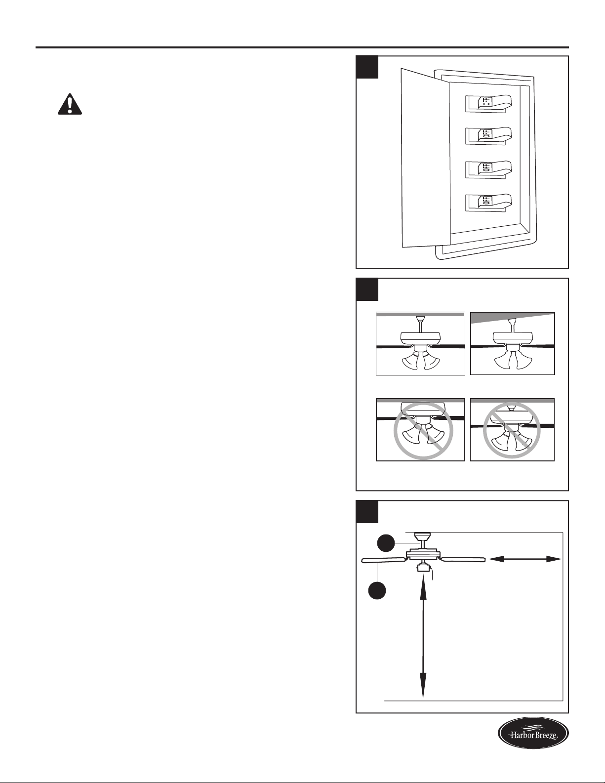
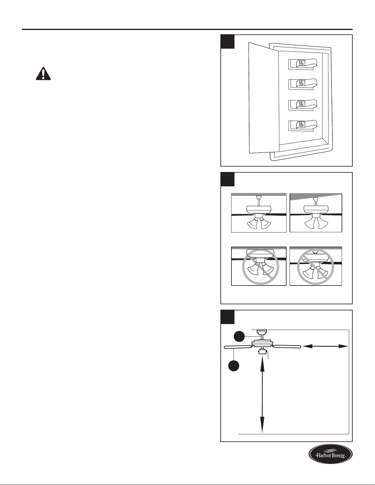
ASSEMBLY INSTRUCTIONS
1. Turn off the circuit breakers and the wall switch to the
fan supply line leads.
DANGER: Failure to disconnect the power
supply prior to installation may result in serious injury
or death.
1
2. Determine the mounting method.
Helpful Hint: Downrod mounting is best suited for
ceilings 8 ft. or higher. For taller ceilings you may
want to use a longer downrod (not included). Angle
mounting is best suited for angled or vaulted ceilings.
A longer downrod is sometimes necessary to ensure
proper blade clearance.
Note: Flushmount installation and closemount
installation are not available for this item.
Important: If using the angle mounting, check to
ensure the ceiling angle is not steeper
than 23°.
2
Downrod Mounting
Flushmount Closemount
Angle Mounting
3. Ensure the blades (I) will be at least 30 in. from any
obstructions. Also check the downrod (D) length to
ensure the blades (I) will be at least 7 ft. above the
oor.
D
I
3
7 ft. Min.
30 in. Min.
8
Lowes.com/harborbreeze
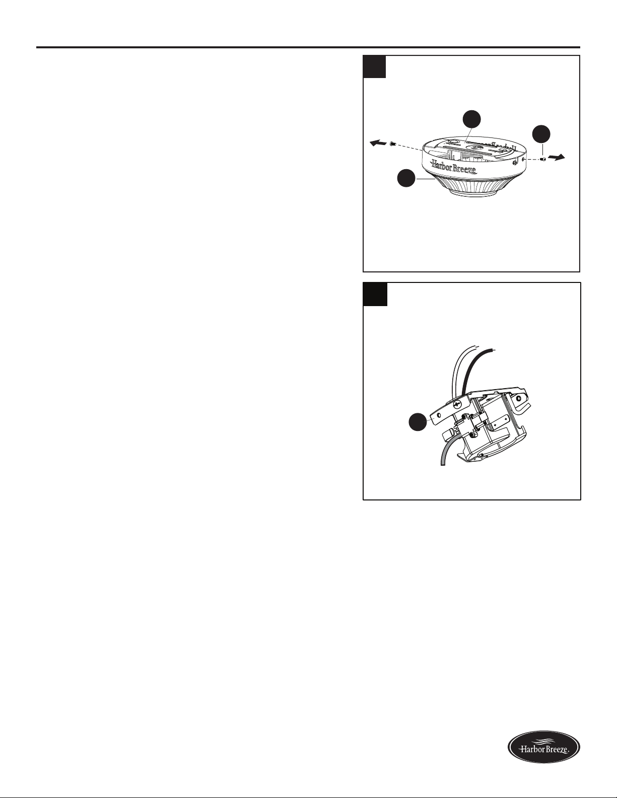
ASSEMBLY INSTRUCTIONS
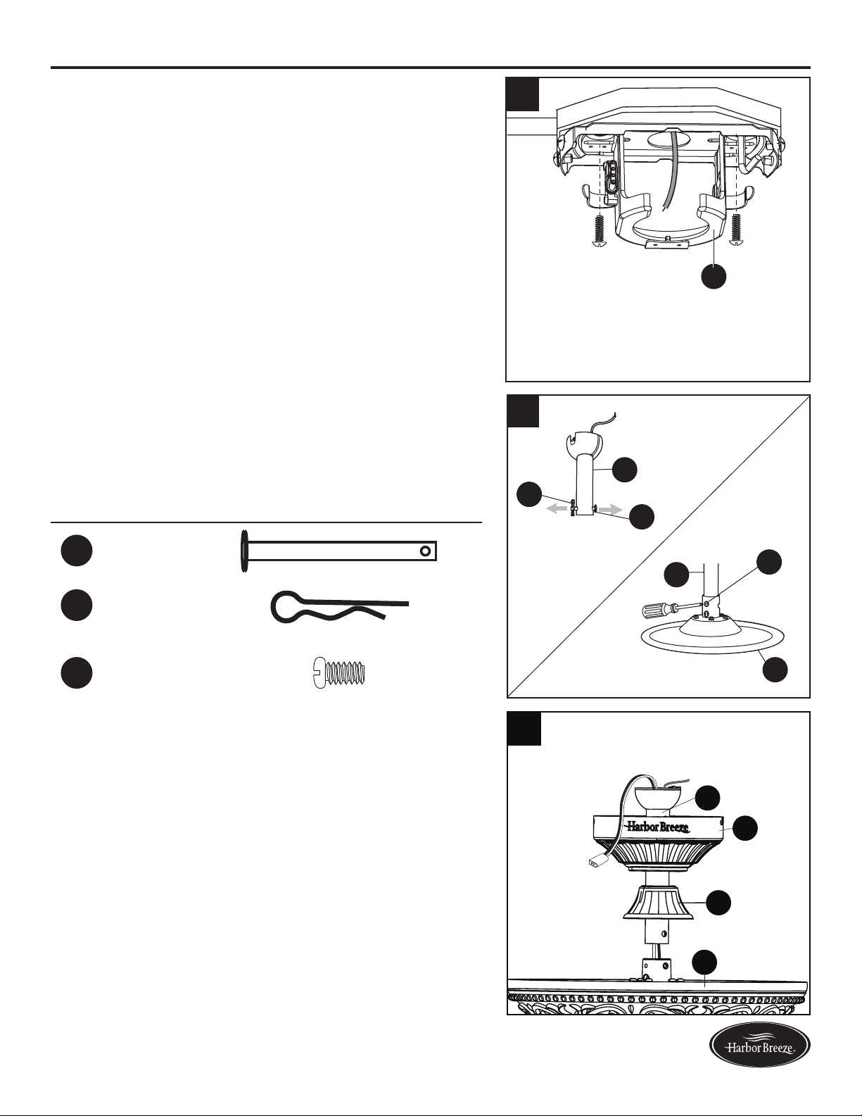
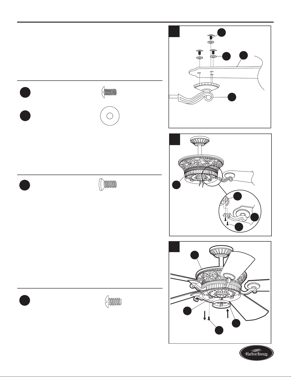
4. Remove the two mounting bracket screws (KK)
from the round holes of the canopy (B). Set aside
for later use. Detach mounting bracket (A) from
canopy (B).
5. Feed black and white wires up from the plug on the
mounting bracket (A) up through the hole in the top.
A
5
4
B
KK
A
9
Lowes.com/harborbreeze
ASSEMBLY INSTRUCTIONS
WARNING:Toreducetheriskofre,electricalshock,orpersonalinjury,wireconnectors
provided with this fan are designed to accept only one 12-gauge house wire and two lead wires from
the fan. If your house wire is larger than 12 gauges and there is more than one house wire to connect
to the two fan lead wires, consult an electrician for the proper size wire connectors to use.
CAUTION: Be sure the outlet box (not included) is properly grounded or that a ground (green or bare) wire
is present.
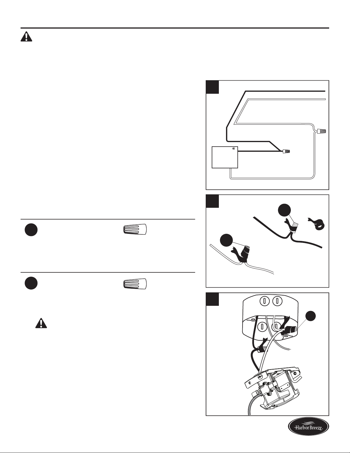
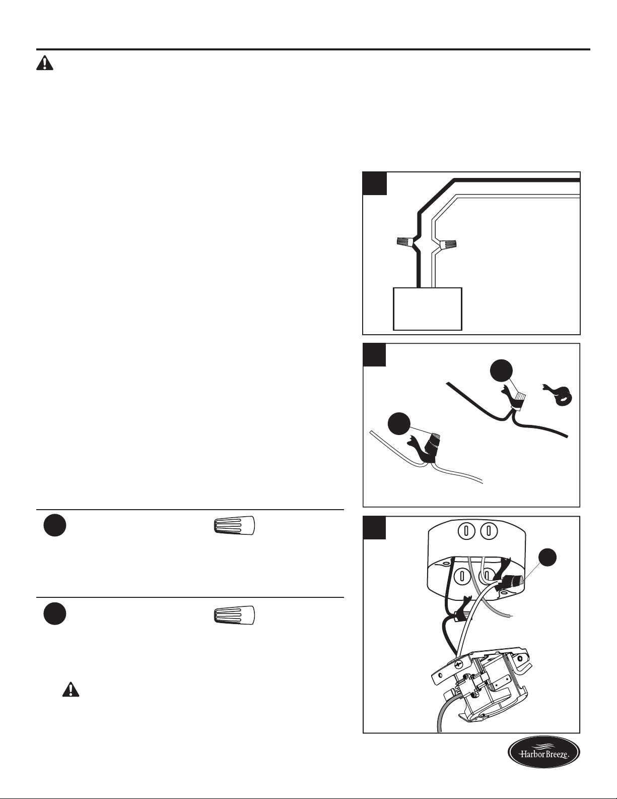
6. Connect with supply and mounting bracket (A) wires
according to the diagram and these steps:
•ConnecttheWhitewirefromthemountingbracket
(A) to the White supply wire.
•ConnecttheBlackwirefromthemountingbracket
(A) to the Black supply wire.
•Secureallwiringconnectionstogetherwithwire
connectors (AA).
Note: The Black wire is hot power for the fan. The
White wire is common for the fan and light kit. The
Green wire is the ground wire and will be connected
later. If house wires are different colors than referred
to above, stop immediately. It is recommended a
professional electrician determines the proper wiring.
Hardware Used
AA
Wire Connector x 2
7. Wrap electrical tape (not included) around each
individual wire connector (AA) down to the wire.
Hardware Used
AA
Wire Connector x 2
8. Turn the spliced/taped wires upward and gently push
the wires and wire connectors (AA) into the outlet box.
WARNING: Ensure no bare wire or wire strands
are visible after making connections. Place the Black
and White wire connections on opposite sides of the
outlet box.
AA
AA
7
AA
8
A
BLACK
WHITE
WHITE
BLACK
FAN
WHITE
6

10
Lowes.com/harborbreeze
ASSEMBLY INSTRUCTIONS
9. Feed green/bare (ground) supply wire down through
the hole in the top of the mounting bracket (A).Secure
the mounting bracket (A) to the outlet box using
screws and washers provided with the outlet box.
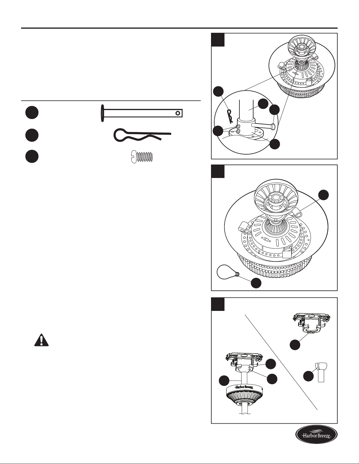
10. Remove the downrod clip (FF) and downrod pin
(EE) from the downrod (D). Then partially loosen the
motor housing set screws (GG) in the yoke at the top
of the motor assembly (F).
Hardware Used
EE
Downrod Pin x 1
FF
Downrod Clip x 1
GG
Motor housing
set screw
x 2
11. Place the downrod (D) into the canopy (B) and yoke
cover (E). Feed the wire harness from the motor
housing (F) through the downrod (D).
F
D
FF
EE
GG
D
9
A
F
E
B
D
11
10
11
Lowes.com/harborbreeze
12
GG
FF
D
EE
S
13
F
P
14
A
O
A
D
O
ASSEMBLY INSTRUCTIONS
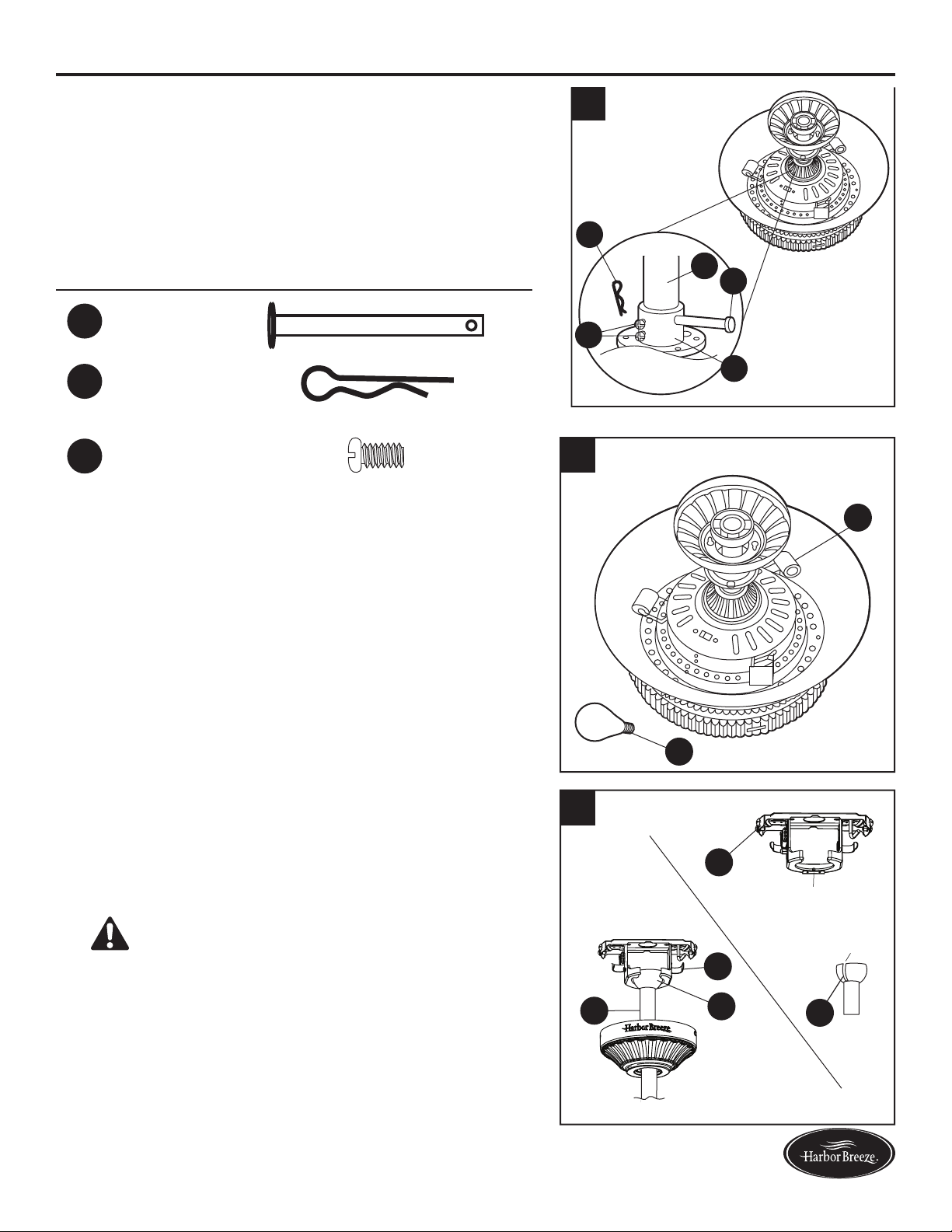
12. Insert the downrod (D) into the coupling (S). Align the
hole in the downrod (D) with the hole in the coupling
(S), then install the downrod pin (EE) through the
coupling (S) and downrod (D). Install the downrod
clip (FF) into the downrod pin (EE) until it snaps into
place. Tighten the motor housing set screws (GG) in
the coupling (S).
Hardware Used
EE
Downrod Pin x 1
FF
Downrod Clip x 1
GG
Motor housing
set screw
x 2
13. Install 25-watt bulbs (P) to each socket on the motor
housing (F).
CAUTION: An energy-saving wattage limiter is
included with the fan. When replacing bulbs, ensure
bulb wattage is less than 190 watts, otherwise the
fan will not function.
14. Carefully lift the downrod (D) onto the mounting
bracket (A). Rotate the downrod (D) until the slot on
the hanger ball (O) engages the tab on the mounting
bracket (A).
DANGER: Be careful when aligning the tab to
the slot. If not fully engaged, the fan may fall, which
may result in serious injury or death.
12
Lowes.com/harborbreeze
ASSEMBLY INSTRUCTIONS
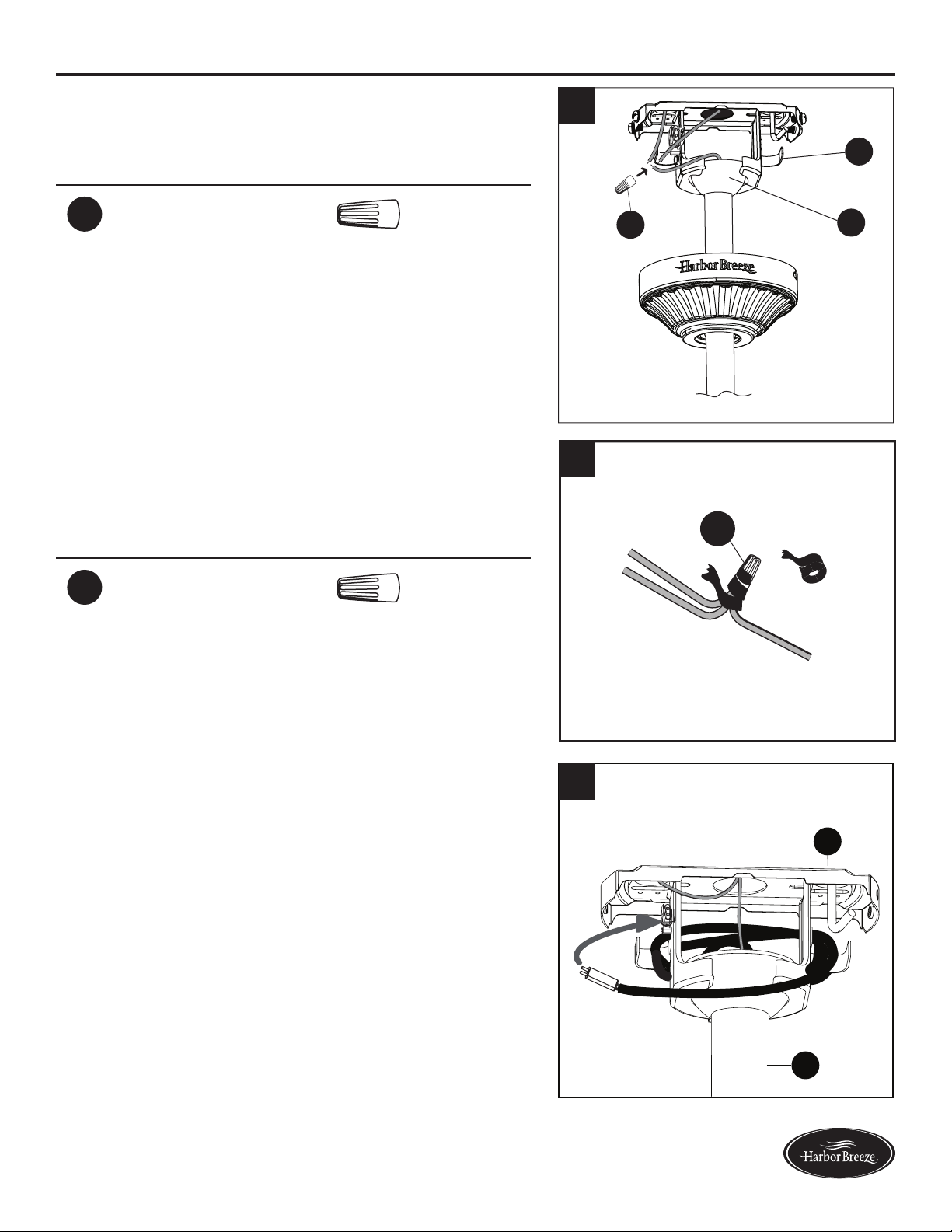
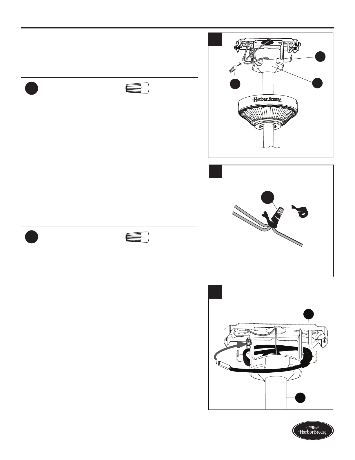
15. Connect the green wires from the downrod ball
(O) and the mounting bracket (A) to the bare/green
(ground) supply wire using a wire connector (AA).
Hardware Used
AA
Wire Connector x 1
16. Wrap electrical tape around the wire connector (AA)
down to the wire. Turn the spliced/taped wires upward
and gently push the wires and wire connector (AA)
into the outlet box.
Hardware Used
AA
Wire Connector x 1
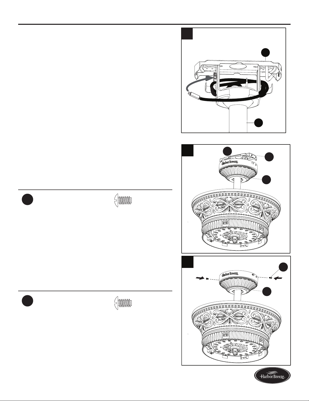
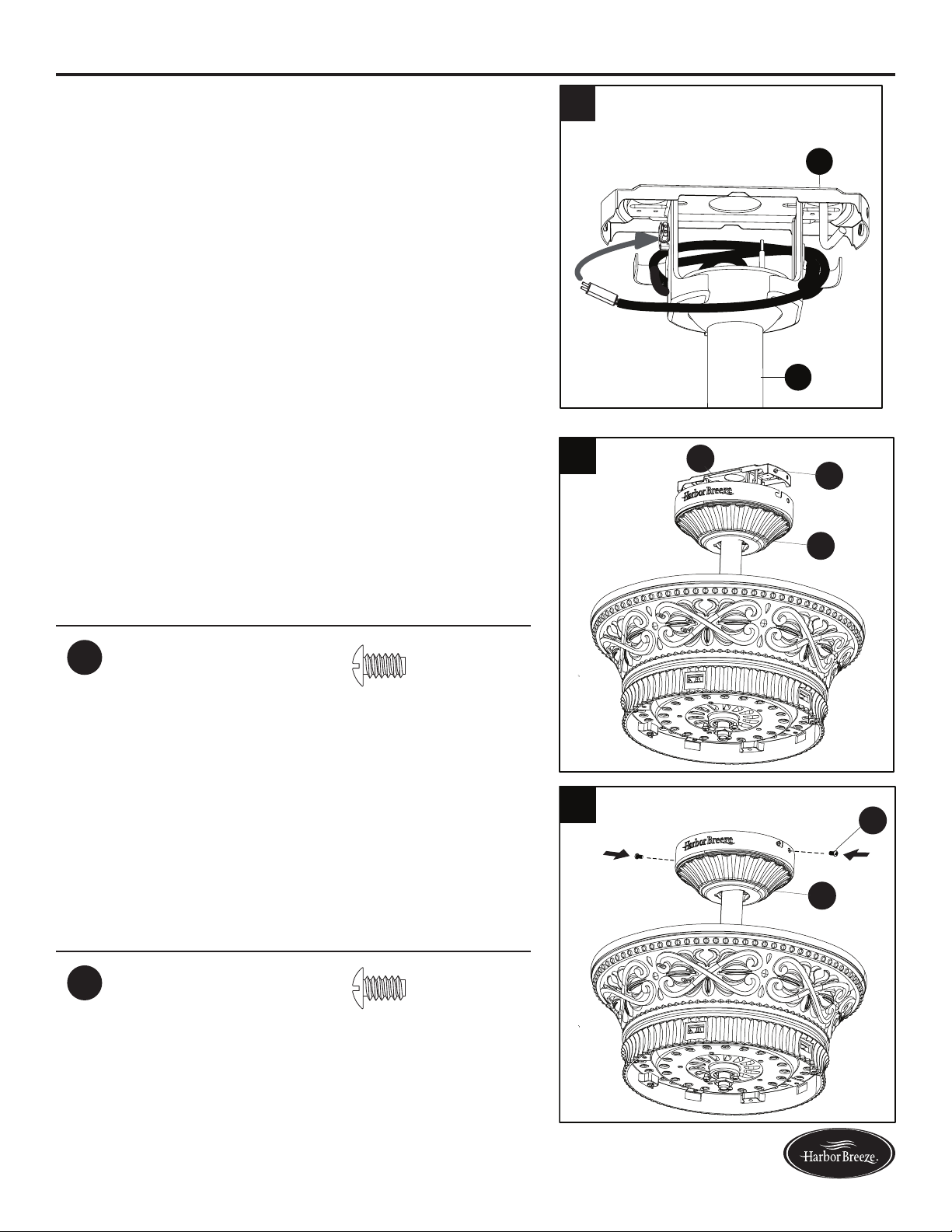
17. Wrap the wire harness coming from the downrod
(D) around the hooks on the back of the mounting
bracket (A).
Note: Extra wire harness length accommodates
longer downrods (sold separately).
A
D
17
15
A
O
AA
AA
16
13
Lowes.com/harborbreeze
ASSEMBLY INSTRUCTIONS
19. Align the keyholes on the canopy (B) with the heads
of the mounting bracket screws (KK) preinstalled
in mounting bracket (A). Lift the canopy (B) up and
rotate it clockwise until the mounting bracket screws
(KK) engage the key slots.
Hardware Used
KK
Mounting Bracket
Screw
x 2
20. Secure the canopy (B) with the mounting bracket
screws (KK) previously removed (Step 4, page 8).
Tighten all mounting bracket screws (KK) securely.
Hardware Used
KK
Mounting Bracket
Screw
x 2
18
KK
B
A
B
KK
ASSEMBLY INSTRUCTIONS
18. Connect the pin connector from the mounting
bracket (A) to the pin connector at the end of the wire
harness.
A
D
18
19
20

14
Lowes.com/harborbreeze
INITIAL INSTALLATION
21. Position one blade arm (J) under a blade (I) and
secure them together with three blade screws (BB)
and blade washers (CC). Do not tighten the blade
screws (BB) until all three have been started. Tighten
each blade screw (BB) starting with the center blade
screw (BB). Repeat this step for all blades (I).
Hardware Used
BB
Blade Screw x 15
CC
Blade Washer x 15
3
J
I
CC
BB
22. Insert one blade assembly into one of the slots on
theywheel(T).Alignthemountingholesonywheel
(T) and blade arm (J), securing with motor screws
(DD). Repeat for the remaining blade assemblies.
Hardware Used
DD
Motor Screw x 10
3
T
T
DD
J
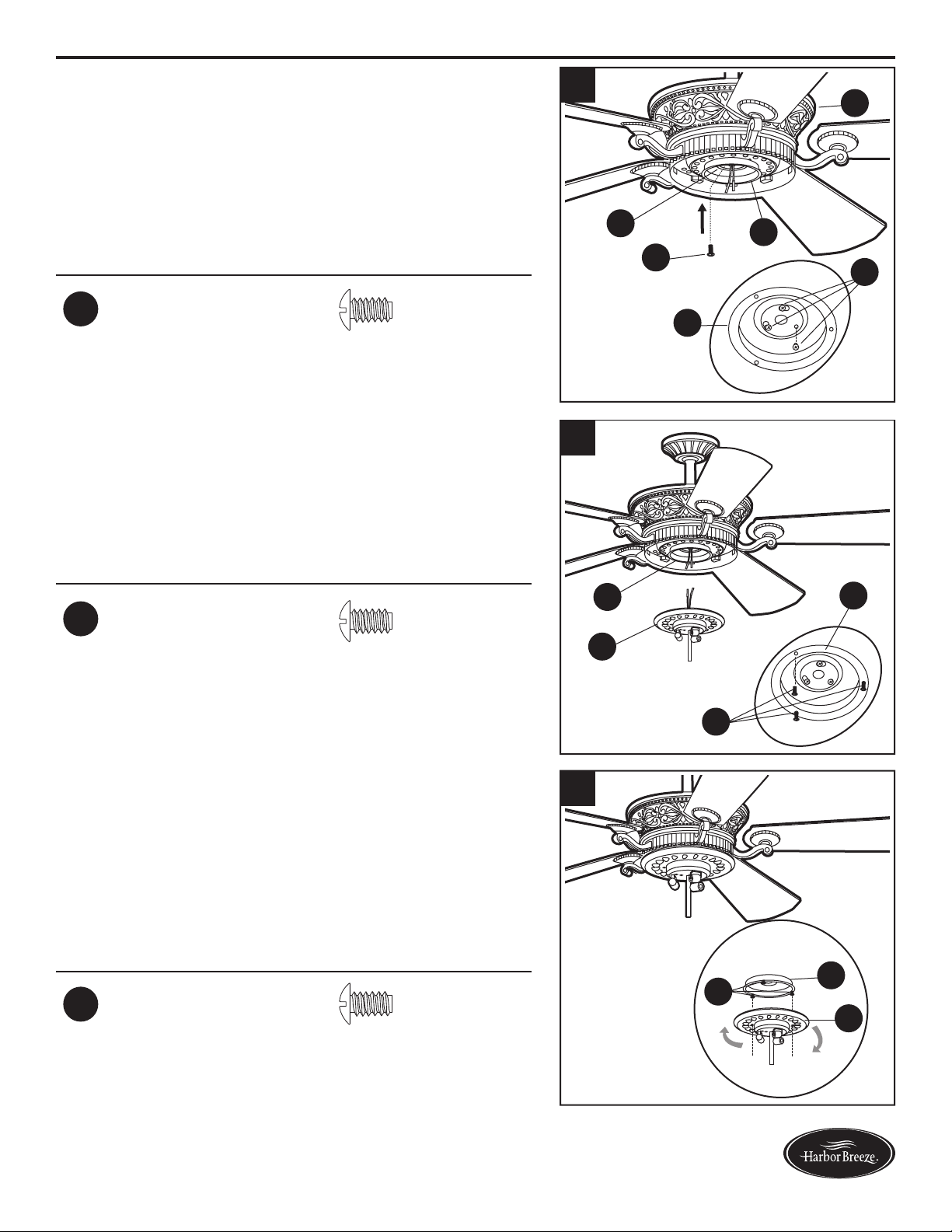
23. Remove one of the switch housing plate screws (LL)
fromthetterplate(R),andloosen(donotremove)
the other two screws. Insert the wires from the motor
housing (F) through the hole in the switch housing (G).
Hardware Used
LL
Switch Housing
Plate Screw
x 3
R
G
LL
F
ASSEMBLY INSTRUCTIONS
21
22
23
15
Lowes.com/harborbreeze
ASSEMBLY INSTRUCTIONS
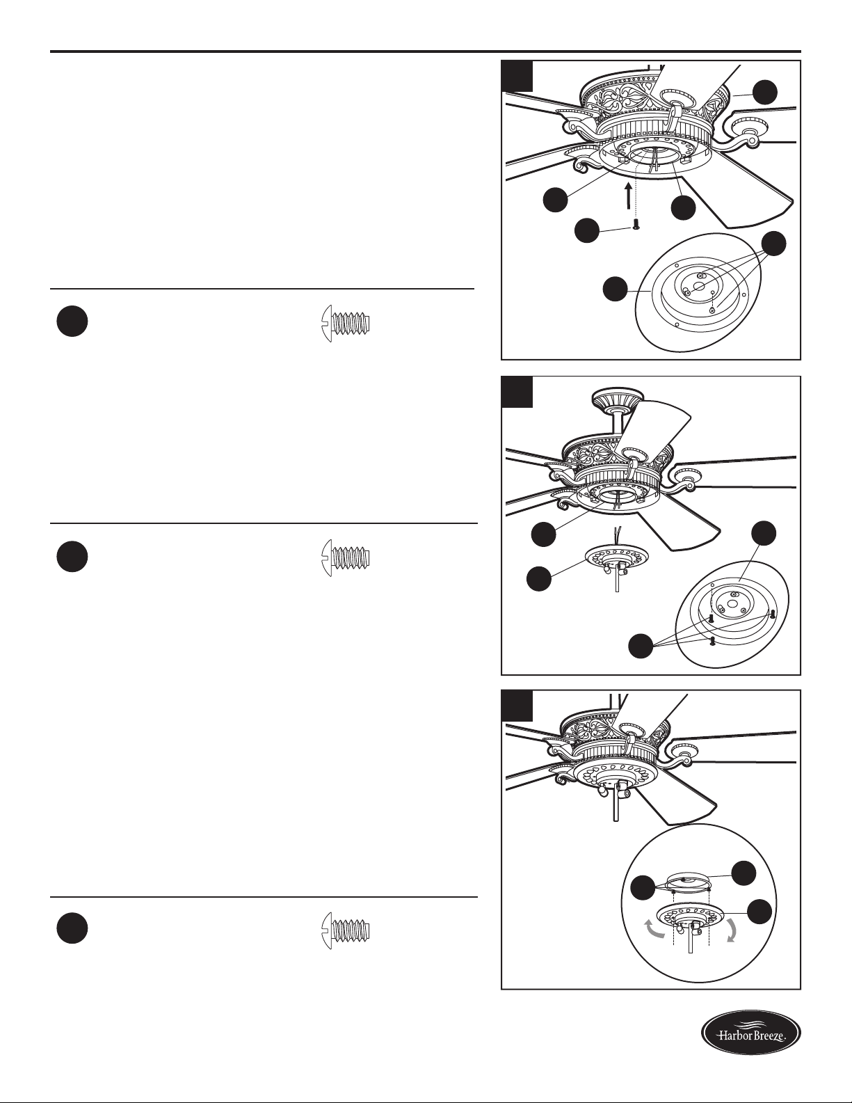
24.Attachtheswitchhousing(G)tothetterplate(R)
by twisting the switch housing (G) until the loosened
switch housing plate screws (LL) engage the key
slots on switch housing (G). Re-install the third
switch housing plate screw (LL) into the closed hole
in the switch housing (G) and securely tighten all
three switch housing plate screws (LL).
Hardware Used
LL
Switch Housing
Plate Screw
x 3
R
G
G
LL
F
LL
25. Remove one of the switch housing screws (MM) from
the switch housing (G), and loosen (do not remove)
the other two. Connect the wire-pin connectors in the
switch housing (G) to the wire-pin connectors from
the light kit (H) -- black to black and white to white.
Hardware Used
MM
Switch Housing
Screw
x 3
G
G
H
MM
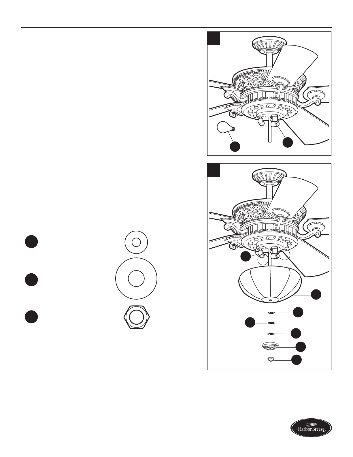
26. Align the slotted holes in the light kit (H) with the
loosened switch housing screws (MM). Twist the light
kit (H) until the screw heads engage the keyslots.
Install the switch housing screw (MM) that was
previously removed into the closed hole in the light
kit (H) and securely tighten all three switch housing
screws (MM).
Hardware Used
MM
Switch Housing
Screw
x 3
G
H
MM
24
25
26
16
Lowes.com/harborbreeze
ASSEMBLY INSTRUCTIONS
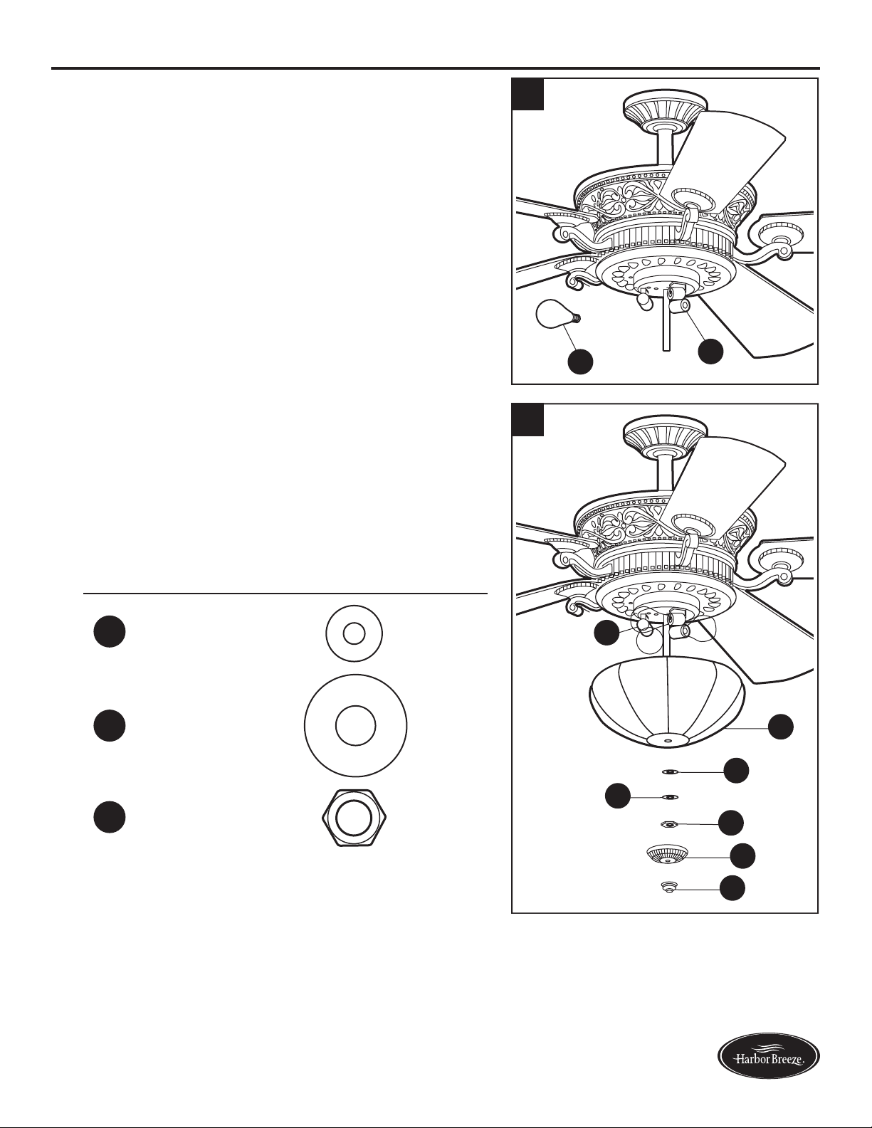
27. Install the 40-watt bulbs (Q) into each socket on the
light kit (H).
CAUTION: An energy-saving wattage limiter is
included with the fan. When replacing bulbs, ensure
bulb wattage is less than 190 watts, otherwise the
fan will not function.
Q
H
28. Lift the glass bowl (K) up to the light kit (H), allowing
the preassembled threaded rod to go through the
center hole in the bottom of the glass bowl (K). Secure
glassbowl(K)withrubberwasher(II),atwasher
(HH),hexnut(JJ),nialcap(L),thennial(M).
Hardware Used
HH
Flat Washer x 1
II
Rubber Washer x 1
JJ
Hex Nut x 1
H
K
II
HH
JJ
L
M
28
27
17
Lowes.com/harborbreeze
OPERATING INSTRUCTIONS
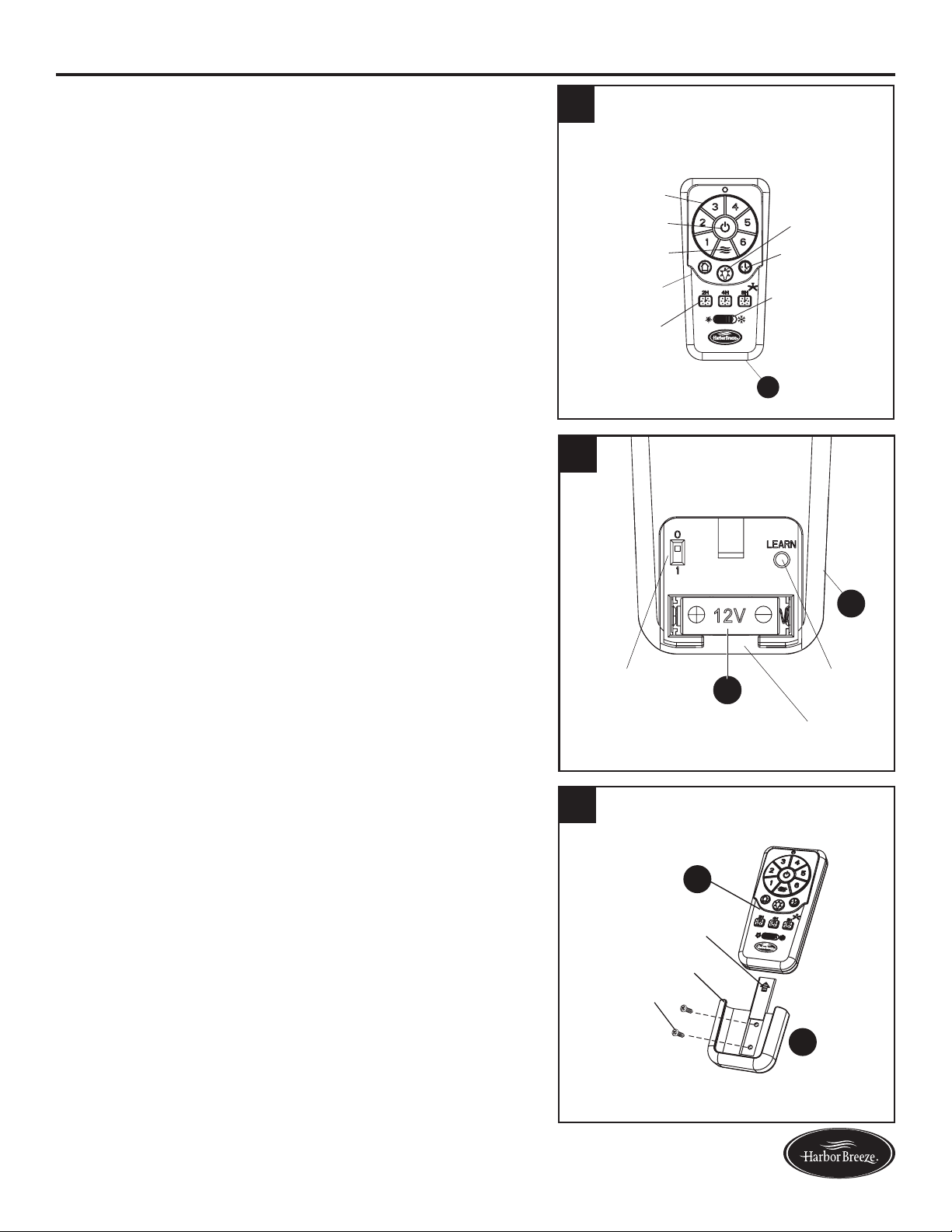
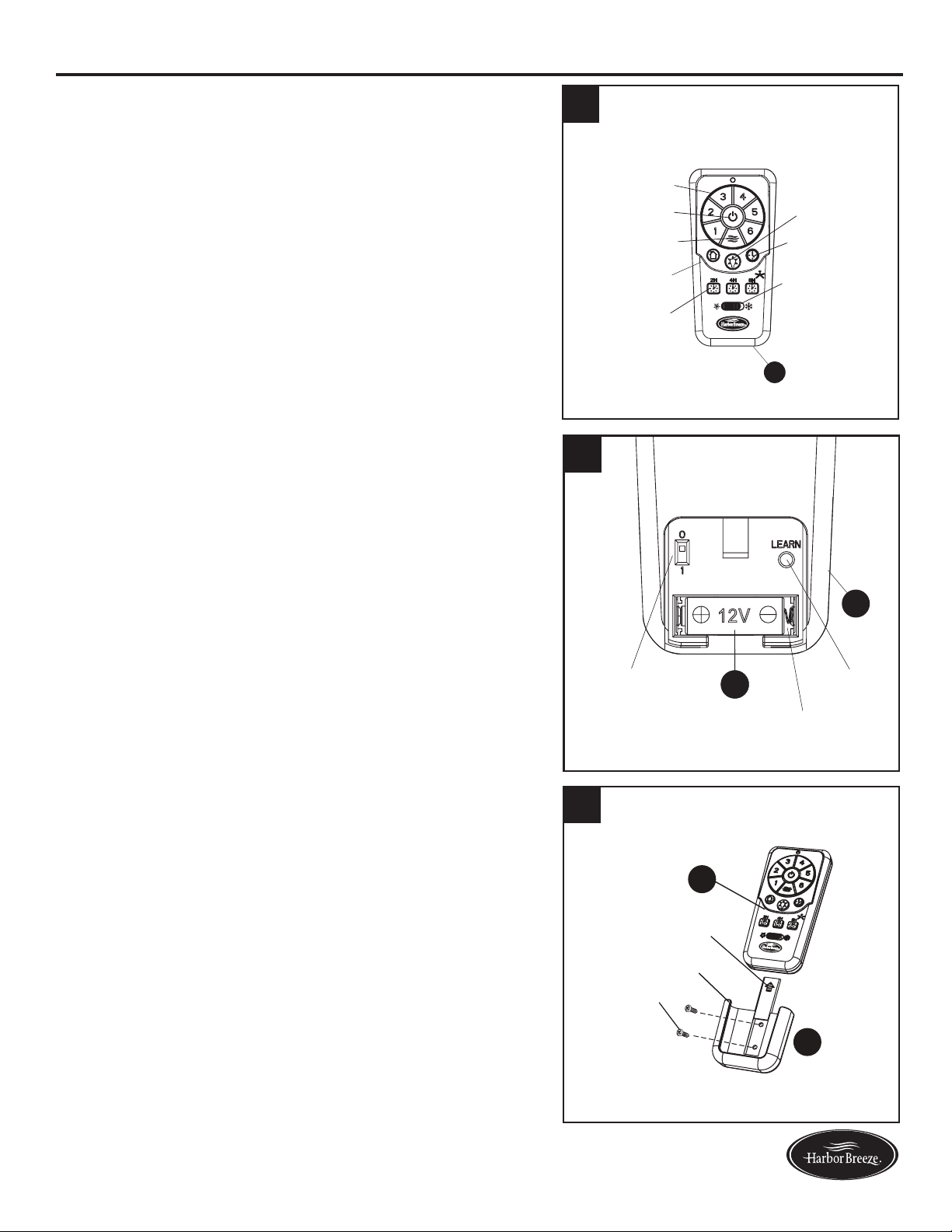
1. To operate the fan using remote control (N), press
and release the following buttons:
Speed Control - Select fan speed 1 (low) - 6 (high).
Fan On/Off - Turns fan off or turns fan on at most
recently selected speed. Press and hold to turn off or
on the sounds from the remote control.
Variable Breeze - Simulates a natural breeze, as if
you were outside. Press any speed control button to
exit this mode.
Random Light - When button is pressed, light blinks
twicetoconrmRandomLightmode.Lightscycle
on for 5-20 minutes and off for 60 minutes simulating
occupancy. Cycle repeats continuously until any
other button is pushed to discontinue Random Light
mode.
Sleep Timer - Turns fan off after (2H) 2 hours, (4H) 4
hours or (8H) 8 hours.
Light On/Off - Cycles lights on/off - (down light on,
up light on, down light off, up light off). Press and
hold the Light On/Off button to turn on/off both up
light and down light.
Delayed Light Off - Delays turning off light for 1
minute which allows safe exit from room.
Season Slide Switch - Changes direction of blade
rotation. For warm weather slide switch to the left
and for cool weather slide switch to the right.
2. Remove battery door from back of the remote control
(N) to access the following:
DIP Switch - Changes signal frequency if
there is interference from another remote (see
troubleshooting for instructions).
Learn - Syncs remote control (N) to receiver (see
troubleshooting for instructions).
Battery Compartment - Install battery (U) into
remote control (N), being mindful of the polarity
markings. When necessary, replace battery (U) with
a new 12-volt battery.
3. Remote control (N) comes equipped with a wall
bracket. If you wish to install the wall bracket, remove
the small plate to expose the screw holes. Insert
wall brackets screws through holes and into wall,
then cover with the previously removed small plate.
Remote control (N) sits inside the wall bracket.
Random Light
Light On/Off
Delayed Light Off
Speed Control
Fan On/Off
Variable Breeze
Sleep Timer
Season Slide
Switch
2
+
+
H
N
12V
2
DIP Switch
Battery Compartment
Learn Button
N
U
1
Wall Bracket
Screw
Small Plate
N
V
3
18
Lowes.com/harborbreeze
CARE AND MAINTENANCE
At least twice each year, lower the canopy to check the downrod assembly, and then tighten all
screws on the fan. Clean the motor housing with only a soft brush or lint-free cloth to avoid scratching
thenish.Cleanthebladeswithalint-freecloth.Youmayoccasionallyapplyalightcoatoffurniture
polish to wood blades for added protection.
Bulb Replacement: Use 25-watt max. or CFL equivalent bulbs for uplights.
Use 40-watt max. or CFL equivalent bulbs for downlights.
Important: Shut off the main power supply before you begin any maintenance task. Do not use water
or a damp cloth to clean the fan.
TROUBLESHOOTING
PROBLEM POSSIBLE CAUSE CORRECTIVE ACTION
The fan does not
move.
1. The season slide switch is
not engaged.
2. The wall switch is turned off.
3. The power is off or the fuse
(breaker) is blown.
4. There is a faulty wire
connection.
1. Firmly push the season slide switch to
either the left or right.
2. Make sure the wall switch is turned
on.
3. Turn the power on or check the fuse
(breaker).
4. Turn the power off and check all
connections at the ceiling outlet box.
The fan is noisy.
1. The blades are loose.
2. There is a cracked blade.
3. The wall control is not
compatible with the fan.
4. The break-in period has not
surpassed.
5. The outlet box is not secure.
6. The mounting bracket is not
secure.
1. Check and tighten all screws that hold
the fan blades to the blade arms and
the motor.
2. Replace the cracked blade.
3. Do not use a full range dimmer switch
to control the fan speed.
4. Run the fan continuously for 24 - 48
hours on medium or high speed for a
“break in” period.
5. Ensure the outlet box is secured to
the building structure.
6. Ensure the mounting bracket is
secured to the outlet box and that the
screws are tight.
19
Lowes.com/harborbreeze
TROUBLESHOOTING
PROBLEM POSSIBLE CAUSE CORRECTIVE ACTION
There is excessive
wobbling.
1. The blades and/or blade are
loose.
2. The blades are unbalanced.
3. The fan mounting is not
secure.
4. The fan is too close to the
vaulted ceiling.
5. The set screw on the motor
housing yoke is loose.
1. Check and tighten all screws that hold
the fan blades to the blade arms and
the blade arms to the motor.
2. Switch one blade with a blade from
the opposite side. Or balance the fan
using a balancing kit (not supplied).
3. Turn off the power. Loosen the
canopy and verify that the mounting
bracket is secure to the electrical
outlet box. The bracket must be
ushwithoutmovementagainstthe
outlet box.
4. Use a longer downrod or move the
fan to another location.
5. Lift up the yoke cover and tighten the
set screw to the yoke until secure.
The fan operates
correctly, but the
lights are not
working.
1. The bulbs are not installed
correctly.
2. The light kit wire-pin
connnectors are not
connected properly.
3. There is a faulty wire
connection.
4. The total power of the light is
exceeding 190W.
1. Re-install the bulb(s).
2. Ensure the wire-pin connectors in the
lightkittterareconnectedproperly.
3. Turn the power off and check all
connections at the ceiling outlet box.
4. The fan comes with a 190W limiter.
When the total watts of the lights is
over 190W, the lights do not work.
Please replace the bulbs with lower
wattage bulbs.
20
Lowes.com/harborbreeze
TROUBLESHOOTING
PROBLEM POSSIBLE CAUSE CORRECTIVE ACTION
Remote
control does
not work.
1. The power to the fan is off or the fuse
is blown.
2. Power surge may have cleared
memory and remote needs to be
re-synced to the receiver.
3. Battery in remote control needs to be
replaced.
4. Interference from another remote.
1. Turn the power on or check the
fuse.
2. Turn power to fan off and back
on. Within 30 seconds press the
LEARN button on back of remote
control (see p. 17).
3. Insert new 12V battery in battery
compartment of the remote control
(see p. 17).
4. The remote control has been
synced to this fan at the factory
and the dip switch as been
switched to “0” inside the battery
compartment. If you have more
than one remote control in the
room, you may need to change the
dip switch settings as follows:
Slide the dip switch to “1” inside
the battery compartment and turn
the power to the fan OFF Then
turn the power ON and you should
hear the remote receiver make two
musical sounds, indicating that
the power supply is normal. Within
30 seconds, press the “LEARN”
key on the back of the transmitter.
Your remote and fan should be
synchronized. To verify successful
synchronization, the ceiling fan
light (if installed) will blink 3 times
and remain ON, and the fan will
rotate on HIGH speed.

21
Lowes.com/harborbreeze
LIFETIME LIMITED WARRANTY
The manufacturer warrants this fan to be free from defects in workmanship and materials present at
time of shipment from the factory for a lifetime from the date of purchase by the original purchaser.
The retailer also warrants that all other fan parts, excluding any glass or plexiglass blades, to be free
from defects in workmanship and material at the time of shipment from the factory for a period of one
year after the date of purchase by the original purchaser. The manufacturer agrees to correct such
defects without charge or at its option replace the ceiling fan with a comparable or superior model.
To obtain warranty service, present a copy of the receipt as proof of purchase. All costs of removing
and reinstalling the product are your responsibility. Any damage to any part such as by accident or
misuseorimproperinstallationorbyafxinganyaccessories,isnotcoveredbythiswarranty.The
manufacturer assumes no responsibility whatsoever for fan installation during the limited lifetime
warranty. Any service performed by an unauthorized person will render the warranty invalid.
Duetovaryingclimateconditions,thiswarrantydoesnotcoveranychangesinbrassnish,including
rusting,pitting,corroding,tarnishingorpeeling.Brassnishesofthistypegivetheirlongestusefullife
when protected from varying weather conditions. Any glass provided with this fan is not covered by
the warranty.
Anyreplacementofdefectivepartsfromtheceilingfanmustbereportedwithintherstyearfromthe
date of purchase. For the balance of the warranty, call our customer service department for return
authorization and shipping instructions so that we may repair or replace the ceiling fan. Any fan or
parts returned improperly is the sole responsibility of the purchaser. There is no other expressed
warranty. The manufacturer disclaims any and all warranties. The duration of any implied warranty
whichcannotbedisclaimedislimitedtothetimeperiodasspeciedintheexpressedwarranty.The
manufacturer shall not be liable for incidental, consequential, or special damages arising out of or
in connection with product use or performance except as may otherwise be accorded by law. This
warrantygivesspeciclegalrights,andyoumayalsohaveotherrightswhichvaryfromstatetostate.
This warranty supersedes all prior warranties.
Note: A small amount of “wobble” is normal and should not be considered a defect.
22
Lowes.com/harborbreeze
REPLACEMENT PARTS LIST
For replacement parts, call our customer service department at 1-800-643-0067, 8 a.m. - 6 p.m., EST,
Monday - Thursday, 8 a.m. - 5 p.m., EST, Friday.
PART DESCRIPTION
A Mounting Bracket 0464470-A
B Canopy 0464470-B
C Canopy Cover 0464470-C
D Downrod 0464470-D
E Yoke Cover 0464470-E
G Switch Housing 0464470-G
H Light Kit 0464470-H
I Blade 0464470-I
J Blade Iron 0464470-J
K Glass Bowl 0464470-K
L Finial Cap 0464470-L
M Finial 0464470-M
N Remote Control 0464470-N
PP Hardware Kit 0464470-PP
AA AB AC AD AG A
H
L
A
M
A
I
AJ AK
AE
PP
A
N
2
+
+
H
Printed in China
Harbor Breeze® is a registered trademark of LF, LLC. All Rights Reserved.
23
Lowes.com/harborbreeze
ARTÍCULO #0464470
VENTILADOR DE
TECHO WAKEFIELD
MODELO #40105
23
Harbor Breeze
®
es una marca registrada de LF, LLC.
Todos los derechos reservados.
¿Preguntas, problemas, piezas faltantes? Antes de volver a la tienda, llame a nuestro
Departamento de Servicio al Cliente al 1-800-643-0067, de 8 a.m. a 6 p.m., hora estándar
del Este, y los viernes de 8 a.m. a 5 p.m., hora estándar del Este.
ADJUNTE SU RECIBO AQUÍ
Número de serie _________________________ Fecha de compra _________________________

24
Lowes.com/harborbreeze
ÍNDICE
Contenido del paquete ............................................................25
Aditamentos. . . . . . . . . . . . . . . . . . . . . . . . . . . . . . . . . . . . . . . . . . . . . . . . . . . . . . . . . . . . . . . . . . . . . 26
Información de seguridad ..........................................................27
Preparación .....................................................................28
Instrucciones de ensamblaje ........................................................29
Instrucciones de funcionamiento .....................................................39
Cuidado y mantenimiento ..........................................................40
Solución de problemas ............................................................40
Garantía limitada de por vida .......................................................43
Lista de piezas de repuesto. . . . . . . . . . . . . . . . . . . . . . . . . . . . . . . . . . . . . . . . . . . . . . . . . . . . . . . . . 44
25
Lowes.com/harborbreeze
CONTENIDO DEL PAQUETE
A
A
A
B
A
C
A
D
A
O
A
GA
H
ALA
M P Q S U V
A
N
A
I
A
JA
K
A
E
A
F
R
T
2
+
+
H
PIEZA DESCRIPCIÓN CANTIDAD
A
Abrazadera de montaje
1
B
Base
1
C
Cubierta de la base
1
D
Varilla
1
E
Cubierta del adaptador
1
F
Carcasa del motor
1
G
Carcasa del interruptor
1
H
Kit de iluminación
1
I
Aspa
5
J
Soporte de hierro del aspa
5
K
Pantalla de vidrio
1
L
Tapa del remate
1
M
Remate
1
N
Control remoto
1
O
Bola para colgar (preensamblada en la varilla [D])
1
P
Bombilla de 25 vatios
3
Q
Bombilla de 40 vatios
3
R
Placa de la carcasa del interruptor (preensamblada en la
carcasa del motor [F])
1
S
Acoplador (preensamblado en la carcasa del motor [F])
1
T
Volante (preensamblado en la carcasa del motor [F])
1
U
Batería
1
V Ensamble de la abrazadera de pared
1
26
Lowes.com/harborbreeze
ADITAMENTOS
Conector de
cables
Cant. 3
y 1 adicional
Tornillo del aspa
Cant. 15
y 1 adicional
Arandela del
aspa
Cant. 15
y 1 adicional
Tornillo del motor
Cant. 10
(preensamblado en
la carcasa del motor
[F])
y 1 adicional
Pasador de
la varilla
Cant. 1
(preensamblado
en la varilla [D])
Sujetador de la
varilla
Cant. 1
(preensamblado
en la varilla [D])
Tornillo de ajuste
de la carcasa del
motor
Cant. 2
(preensamblado
en el ensamblaje
del motor [F])
Arandela plana
Cant. 1
Arandela de goma
Cant. 1
Tuerca
hexagonal
Cant. 1
Tornillo de la
abrazadera
de montaje
Cant. 4
(preensamblado
en la abrazadera
de montaje [A])
Tornillo de la
placa de la
carcasa del
interruptor
Cant. 3
(preensamblado
en la placa de
la carcasa del
interruptor [R])
Tornillo de la
carcasa del
interruptor
Cant. 3
(preensamblado
en la carcasa del
interruptor [G])
AA BB CC DD EE
FF HH
GG
MM
II
JJ LLKK

27
Lowes.com/harborbreeze
INFORMACIÓN DE SEGURIDAD
Lea y comprenda completamente este manual antes de intentar ensamblar, usar o instalar el producto.
• Antes de comenzar a instalar el ventilador, desconecte el suministro de electricidad; para esto retire
los fusibles o coloque los interruptores de circuito en la posición de apagado.
• Asegúrese de que todas las conexiones eléctricas cumplan con los códigos y ordenanzas locales, el
National Electrical Code (Código Nacional de Electricidad) y la norma ANSI/NFPA 70-199. Si no está
familiarizadoconlainstalacióndelcableadoeléctrico,contrateaunelectricistacalicadooconsulte
un manual de cableado para hacerlo usted mismo.
• Asegúrese de que en el lugar de instalación que elija se pueda establecer una distancia mínima
de 2,13 m desde las aspas hasta el piso, y de al menos 76,20 cm desde los extremos de las aspas
hasta cualquier obstáculo.
• El peso neto de este ventilador es: 11,24 kg.
PELIGRO: si utiliza una caja de salida existente, asegúrese de que esté bien sujeta a la estructura
deledicioyquepuedasostenerelpesocompletodelventilador.Elincumplimientodedichopaso
podría provocar lesiones graves o la muerte. La estabilidad de la caja de salida es fundamental para
minimizar el tambaleo y el ruido en el ventilador una vez que la instalación esté completa.
ADVERTENCIA: para evitar lesiones personales, puede ser necesario usar guantes al manipular
laspiezasdelventiladorconbordeslosos.
ADVERTENCIA: el uso de un regulador de intensidad de rango completo para controlar la velocidad
del ventilador provocará un zumbido intenso del ventilador. Para reducir el riesgo de incendios o descargas
eléctricas, NO use un regulador de intensidad de rango completo para controlar la velocidad del ventilador.
ADVERTENCIA: para reducir el riesgo de incendios, descargas eléctricas o lesiones personales,
instale el ventilador en una caja de salida marcada como “ACCEPTABLE FOR FAN SUPPORT”
(APTA PARA SOSTENER UN VENTILADOR) y utilice los tornillos de montaje incluidos en la caja de
salida. La mayoría de las cajas de salida que se usan comúnmente para sostener las lámparas no son
aptas para sostener un ventilador y puede ser necesario reemplazarlas. Si tiene dudas, consulte a un
electricistacalicado.Asegurelacajadesalidadirectamentealaestructuradeledicio.Lacajadesalida
y su soporte deben ser capaces de sostener el peso del ventilador en movimiento (al menos 15,88 kg).
NO use una caja de salida de plástico.
ADVERTENCIA: para reducir el riesgo de incendios, descargas eléctricas o lesiones personales,
los conectores de cables proporcionados con este ventilador están diseñados para soportar solo un cable
de la casa de calibre 12 y dos cables conductores del ventilador. Si el cable de la casa es de un calibre
superior a 12 o hay más de un cable de la casa para conectar los dos cables conductores del ventilador,
pregúntele a un electricista cuál es el tamaño adecuado de los conectores de cables que debe utilizar.
ADVERTENCIA: para reducir el riesgo de incendios o descargas eléctricas, no use el ventilador
con dispositivos de control de velocidad para estado sólido ni controle la velocidad del ventilador con un
regulador de intensidad de rango completo.
ADVERTENCIA: para reducir el riesgo de incendios, descargas eléctricas o lesiones personales,
no doble los brazos de las aspas al instalarlas, al equilibrarlas o al limpiar el ventilador. No introduzca
objetos entre las aspas en movimiento.
ADVERTENCIA: para reducir el riesgo de lesiones personales, use solo las piezas que se
incluyen con este ventilador. El uso de piezas DISTINTAS a aquellas que se incluyen con este
ventilador anulará la garantía.

28
Lowes.com/harborbreeze
INFORMACIÓN DE SEGURIDAD
PRECAUCIÓN: Lea todas las instrucciones y la información de seguridad antes de instalar el nuevo
ventilador. Revise los diagramas de ensamblaje adjuntos.
PRECAUCIÓN: Asegúrese de que la caja de salida cuente con la puesta a tierra adecuada o de que
haya un conductor (verde o desnudo) de tierra.
PRECAUCIÓN: Revise cuidadosamente todos los tornillos, pernos y tuercas del ensamble del motor
del ventilador para comprobar que estén seguros.
PRECAUCIÓN: Esteequiposeprobóysevericóquecumplelasnormasdeundispositivo
digital clase B, conforme a la Sección 15 de las reglas de la FCC. Estas normas se diseñaron
para proporcionar una protección razonable contra la interferencia perjudicial en una instalación
residencial. Este equipo genera, utiliza y puede irradiar energía de radiofrecuencia y, si no se
instala y usa de acuerdo con las instrucciones, puede causar interferencia perjudicial a las
comunicaciones de radio.
PREPARACIÓN
Antes de comenzar a ensamblar este producto, asegúrese de tener todas las piezas. Compare todas
las piezas con la lista del contenido del paquete y con la lista de aditamentos. No intente ensamblar
el producto si falta alguna pieza o si estas están dañadas.
Después de abrir la parte superior de la caja, retire el paquete de aditamentos para montaje de los
accesoriosdeespuma.Luego,quiteelmotordelensambleycolóqueloenunasuperciesuave,
como una alfombra, para evitar dañar el acabado.
Tiempo estimado de ensamblaje: 120 minutos
Herramientas necesarias para el ensamblaje (no se incluyen): cinta aislante, destornillador Phillips,
pinzas, gafas de seguridad, escalera de tijera y pinzas pelacables.
Herramientas útiles (no se incluyen): Luz de prueba de CA, cinta métrica, manual de cableado y
pinzas cortacables
29
Lowes.com/harborbreeze
ASSEMBLY INSTRUCTIONS
1. Gire las abrazaderas de circuito y el interruptor de
pared hacia los conductores de la línea de suministro
del ventilador.
PELIGRO: si no interrumpe el suministro
de electricidad antes de la instalación, pueden
producirse lesiones graves o la muerte.
1
2. Determine el método de instalación que utilizará.
Sugerencia útil: el montaje de varilla es más
apropiado para los techos de 2,44 m de alto o de mayor
altura. Para techos más altos, se recomienda utilizar
una varilla más larga (no incluida). El montaje en ángulo
es mejor para los techos en ángulo o de bóveda. En
ocasiones, es necesaria una varilla más larga para
asegurar una adecuada separación de las aspas.
Nota: La instalación de montaje al ras y la
instalación de montaje cerrado no están disponibles
para este artículo.
Importante:sirealizaelmontajeenángulo,verique
que el ángulo del techo no tenga una inclinación
superior a los 23°.
2
Montaje de estándar
Montaje al ras Montaje Cerrado
Montaje en ángulo
3. Asegúrese de que las aspas (I) estén al menos a 76,20
cmdetodaobstrucción.Tambiénveriqueellargode
la varilla (D) para asegurarse de que las aspas (I) estén
al menos a 2,13 m por encima del piso.
A
I
3
2,13 m
como min.
76,20 cm
como min.

30
Lowes.com/harborbreeze
INSTRUCCIONES DE ENSAMBLAJE
4. Retire los dos tornillos de la abrazadera de montaje
(KK)delosoriciosredondosdelabase.Déjelos
a un lado para usarlos posteriormente. Retire la
abrazadera de montaje (A) de la base (B).
5. Pase el conductor negro y el conductor blanco del
enchufe en la abrazadera de montaje (A) hacia el
oricioenlapartesuperior.
A
5
4
B
KK
A
31
Lowes.com/harborbreeze
INSTRUCCIONES DE ENSAMBLAJE
ADVERTENCIA: para reducir el riesgo de incendios, descargas eléctricas o lesiones
personales, los conectores de cables proporcionados con este ventilador están diseñados
para soportar solo un cable de la casa de calibre 12 y dos cables conductores del ventilador.
Si el cable de la casa es de un calibre superior a 12 o hay más de un cable de la casa para
conectar los dos cables conductores del ventilador, pregúntele a un electricista cuál es el tamaño
adecuado de los conectores de cables que debe utilizar.
PRECAUCIÓN: asegúrese de que la caja de salida cuente con la puesta a tierra adecuada o de que
haya un cable (verde o desnudo) de tierra.
6. Conecte con los conductores de suministro y de
la abrazadera de montaje (A) según el diagrama y
siguiendo estos pasos:
•Conecteelconductorblancodelaabrazaderade
montaje (A) al conductor de suministro blanco.
•Conectelosconductoresazulynegrodela
abrazadera de montaje (A) al conductor de suministro
negro.
•Aseguretodaslasconexionesdelcableadojuntocon
los conectores de cables (AA).
Nota: El conductor negro le proporciona energía al
ventilador. El conductor blanco es el conductor común.
El conductor azul le proporciona energía al kit de
iluminación (se vende por separado; las instrucciones
de cableado serán distintas si compra el kit de
iluminación opcional. Consulte las instrucciones del
fabricante del kit de iluminación). El conductor verde
es el conductor de puesta a tierra y se conectará
posteriormente. Si los conductores interiores son de
color diferente a los mencionados anteriormente,
deténgase de inmediato. Se recomienda que un
electricista profesional determine el cableado adecuado.
Aditamentos utilizados
AA
Conector
de cables
x 2
7. Wrap electrical tape (not included) around each
individual wire connector (AA) down to the wire.
Aditamentos utilizados
AA
Conector
de cables
x 2
8. Gire los cables empalmados o cubiertos con cinta hacia
arriba y empuje suavemente los cables y los conectores
de cables (AA) hacia dentro de la caja de salida.
ADVERTENCIA: asegúrese de que no haya
conductoresdesnudosnilamentosdecables
visibles después de realizar las conexiones. Coloque
las conexiones de cables verde y blanco en el lado
opuesto de la caja de salida con respecto a las
conexiones de cables negro y azul.
AA
AA
7
AA
8
A
Abrazadera
de montaje
Negro
Blanco
Negro
Blanco
6
32
Lowes.com/harborbreeze
INSTRUCCIONES DE ENSAMBLAJE
9. Pase el conductor de suministro verde/desnudo (de
puestaatierra)poreloricioenlapartesuperiorde
la abrazadera de montaje (A). Asegure la abrazadera
de montaje (A) a la caja de salida con los tornillos y
las arandelas que incluye la caja de salida.
10. Retire el pasador de la varilla (EE) y el sujetador
delavarilla(FF)delavarillade(D).Luegoaoje
parcialmente los tornillos de ajuste de la carcasa del
motor (GG) que se encuentran en la horquilla de la
parte superior de la carcasa del motor (F).
Aditamentos utilizados
EE
Pasador
de la varilla
x 1
FF
Sujetador
de la varilla
x 1
GG
Tornillo de
ajuste de la
carcasa del
motor
x 2
11. Inserte la varilla (D) a través de la base (B) y la
cubierta de la horquilla (E). Pase los cables desde el
ensamblaje del motor (F) a través de la varilla (D).
F
D
FF
EE
GG
D
9
A
F
E
B
D
11
10
33
Lowes.com/harborbreeze
12
GG
FF
D
EE
S
13
F
P
15
A
O
A
D
O
Lengüeta
Ranura
INSTRUCCIONES DE ENSAMBLAJE
12. Inserte la varilla (D) en el acoplador (S). Alinee
eloriciodelavarilla(D)coneloriciodel
acoplador (S). Instale el pasador de la varilla (EE)
a través del acoplador (S) y de la varilla (D). Instale
el sujetador de la varilla (FF) en el pasador de
la varilla (EE) hasta que calce a presión en su
lugar. Apriete los tornillos del acoplador (GG) en
el acoplador (S).
Aditamentos utilizados
EE
Pasador
de la varilla
x 1
FF
Sujetador
de la varilla
x 1
GG
Tornillo de
ajuste de la
carcasa del
motor
x 2
13. Instale bombillas de 25 vatios (P) en cada
portalámpara de la carcasa del motor (F).
PRECAUCIÓN:
El ventilador cuenta con un fusible
limitador de potencia a 190 vatios. Si los vatios
totalesl de las luces supera los 190 vatios, las luces
no funcionan. Reemplace las bombillas por unas de
menor vataje.
14. Instale el extremo con la bola de la varilla (D) en la
abertura de la abrazadera de montaje (A). Alinee la
ranura de la bola con la lengüeta de la abrazadera
de montaje (A) La varilla no debe girar si esto se
hace correctamente.
PELIGRO: si no alinea la ranura de la bola con
la lengüeta, pueden producirse lesiones graves o la
muerte.
34
Lowes.com/harborbreeze
INSTRUCCIONES DE ENSAMBLAJE
15. Conecte los conductores verdes de la bola de la
varilla (O) y de la abrazadera de montaje (A) al
conductor de suministro desnudo/verde (de puesta a
tierra) con un conector para cables (AA).
Aditamentos utilizados
AA
Conector
de cables
x 1
16. Cubra con cinta aislante (no se incluye) cada
conector de cables individual (AA) hacia abajo del
cable. Gire los cables empalmados o cubiertos con
cinta hacia arriba y empuje suavemente los cables y
los conectores de cables (AA) hacia dentro de la caja
de salida.
Aditamentos utilizados
AA
Conector
de cables
x 1
17. Envuelva el arnés de cableado que proviene de
la varilla (D) alrededor de los ganchos en la parte
posterior de la abrazadera de montaje (A).
Nota: El arnés de cableado más largo se adapta a
varillas más largas (se vende por separado).
A
D
17
15
A
O
AA
AA
16
35
Lowes.com/harborbreeze
INSTRUCCIONES DE ENSAMBLAJE
19.Alineelosoriciosdelabase(B)conlacabeza
de los tornillos de la abrazadera de montaje (KK)
preinstalados en la abrazadera de montaje (A).
Levante la base (B) y gírela en dirección de las
manecillas del reloj hasta que los tornillos de la
abrazadera de montaje (KK) calcen por completo en
los chaveteros.
Aditamentos utilizados
KK
Tornillo de la
abrazadera
de montaje
x 2
20. Asegure la base (B) con los tornillos de la
abrazadera de montaje (KK) que retiró previamente
(paso 4, página 30). Apriete bien todos los tornillos
de la abrazadera de montaje (KK).
Aditamentos utilizados
KK
Tornillo de la
abrazadera
de montaje
x 2
18
KK
B
A
B
KK
INSTRUCCIONES DE ENSAMBLAJE
18. Conecte el conector del pasador de la abrazadera de
montaje (A) al conector del pasador al extremo del
arnés de cableado que proviene de la varilla (D).
A
D
18
19
20
36
Lowes.com/harborbreeze
21. Coloque un soporte de hierro del aspa (J) debajo del
aspa (I) y fíjelos con los tres tornillos del aspa (BB)
y las arandelas del aspa (CC). No apriete los
tornillos de las aspas (BB) hasta que los tres estén
colocados. Apriete cada tornillo del aspa (BB),
comenzando por el que está en el centro (BB).
Repita este paso para todas las aspas (I).
Aditamentos utilizados
BB
Tornillo
del aspa
x 15
CC
Arandela
del aspa
x 15
3
J
I
CC
BB
22. Inserte un ensamblaje del aspa en una de las ranuras
delvolante(T).Alineelosoriciosdemontajeyapriete
el ensamblaje del aspa utilizando dos tornillos del
motor (DD). Repita los pasos para el ensamblaje de
las aspas restantes.
Aditamentos utilizados
DD
Tornillo
del motor
x 10
3
T
T
DD
J
23. Retire uno de los tornillos de la placa de la carcasa
del interruptor (LL) de la placa de la carcasa
delinterruptor(R)yaojelosotrosdostornillos
(sin sacarlos). Inserte los cables desde la carcasa
delmotor(F)atravésdeloriciodelacarcasadel
interruptor (G).
Aditamentos utilizados
LL
Tornillo de la placa
de la carcasa del
interruptor
x 3
R
G
LL
F
INSTRUCCIONES DE ENSAMBLAJE
21
22
23
37
Lowes.com/harborbreeze
INSTRUCCIONES DE ENSAMBLAJE
24. Fije la carcasa del interruptor (G) en la placa de la
carcasa del interruptor (R); lo puede hacer ubicando los
oriciosdelchaveterodelacarcasadelinterruptor(G)
en los dos tornillos sueltos de la placa de la carcasa
del interruptor (LL). Gire la carcasa del interruptor (G)
hasta que las cabezas de los tornillos calcen con los
chaveteros. Vuelva a instalar el tercer tornillo de la
placadelacarcasadelinterruptor(LL)eneloricio
cerrado de la carcasa del interruptor (G) y apriete
rmementelostrestornillosdelaplacadelacarcasa
del interruptor (LL).
Aditamentos utilizados
LL
Tornillo de la placa
de la carcasa del
interruptor
x 3
R
G
G
LL
F
LL
25. Retire uno de los tornillos de la carcasa del
interruptor (MM) de la carcasa del interruptor (G)
yaojelosotrosdostornillos(sinsacarlos).
Conecte los cables de la carcasa del interruptor (G)
con los cables del kit de iluminación (H). Conecte los
cables negros y blancos entre sí.
Aditamentos utilizados
MM
Tornillo de la
carcasa del
interruptor
x 3
G
G
H
MM
26.Alineelosoriciosranuradosdelkitdeiluminación
(H)conlostornillosojosdelacarcasadel
interruptor (MM). Gire el kit de iluminación (H)
hasta que las cabezas de los tornillos calcen en
los chaveteros. Instale el tornillo de la carcasa del
interruptor (MM) que se retiró anteriormente en el
oriciocerradodelkitdeiluminación(H)yapriete
rmementelostrestornillosdelacarcasadel
interruptor (MM).
Aditamentos utilizados
MM
Tornillo de la
carcasa del
interruptor
x 3
G
H
MM
24
25
26
38
Lowes.com/harborbreeze
INSTRUCCIONES DE ENSAMBLAJE
27. Instale las bombillas de 40 vatios (Q) en cada
portalámpara del kit de iluminación (H).
PRECAUCIÓN:
El ventilador cuenta con un fusible
limitador de potencia a 190 vatios. Si los vatios
totalesl de las luces supera los 190 vatios, las luces
no funcionan. Reemplace las bombillas por unas de
menor vataje
Q
H
28. Levante la pantalla de vidrio (K) hasta el kit de
iluminación (H) y permita que la varilla roscada se
desplaceatravésdeloriciocentralenlaparte
inferior de la pantalla de vidrio (K). Mientras sostiene
la pantalla de vidrio (K), coloque la arandela de
silicona (II) y la arandela plana (HH), y enrosque
la tuerca hexagonal (JJ) en el tubo. Finalmente,
apriételas con la tapa del remate (L) y el remate (M).
Aditamentos utilizados
HH
Arandela plana x 1
II
Arandela de
goma
x 1
JJ
Tuerca
hexagonal
x 1
H
K
II
HH
JJ
L
M
28
27
39
Lowes.com/harborbreeze
INSTRUCCIONES DE FUNCIONAMIENTO
1. Para hacer funcionar el ventilador con el control remoto
(M), presione y suelte los siguientes botones:
Seleccione la velocidad - 1 (baja) a 6 (alta).
Encendido/apagado - Enciende o apaga el ventilador
en la última velocidad seleccionada. Mantenga
presionado para apagar o encender los sonidos desde
el control remoto.
Brisa variable - Imita una brisa natural, como si
estuviera al aire libre. Presione cualquier botón de
control de velocidad para salir de este modo.
Luz de seguridad - Al presionar este botón, la luz titila
dosvecesparaconrmarelmododeluzdeseguridad.
El ciclo de la luz se activa durante 5 a 20 minutos y se
apaga durante 60 minutos para hacer creer que hay
alguien. El ciclo se repite de forma continua hasta que
se presione cualquier otro botón para detener el modo
de luz seguridad.
Temporizador de apagado automático - Apaga el ventilador
después de 2 horas (2H), 4 horas (4H) u 8 horas (8H).
Encendido/apagado de luz -Enciende y apaga la luz
(luz hacia abajo encendida, luz hacia arriba encendida, luz
hacia abajo apagada, luz hacia arriba apagada). Mantenga
presionado el botón de encendido/apagado de luz para
encender/apagar la luz hacia arriba y la luz hacia abajo.
Apagado de luz con retardo - Retarda el apagado de
la luz un minuto, lo que permite salir de forma segura de
la habitación.
Interruptor deslizante de temporada - Cambia la
dirección de giro de las aspas. En climas cálidos,
deslice el interruptor a la izquierda y en climas fríos
deslice el interruptor a la derecha.
2. Retire la puerta de la batería de la parte posterior del
control remoto (N) para acceder a lo siguiente:
Interruptor DIP - Cambia la frecuencia de la señal si
hay interferencia de otro control remoto (consulte las
instrucciones en la parte de solución de problemas).
Learn - Sincroniza el control remoto (N) con el receptor
(consulte las instrucciones en la parte de solución de
problemas).
Compartimiento de la batería - De ser necesario,
reemplace la batería preinstalada (U) con una batería
nueva de 12 voltios.
3. Control remoto (N)) incluye una abrazadera de pared.
Si desea instalar el abrazadera de pared, retire la placa
pequeñoparaexponerlosoriciosdelostornillos.
Inserte los tornillos de abrazadera de pared a través de
losoriciosenlaparedy,acontinuación,cubrirconla
pequeña placa que quitó antes. Control remoto (N)) se
encuentra en el interior de la abrazadera de pared.
Luz de seguridad
Encendido/
apagado de luz
Apagado de luz
con retardo
Seleccione
la velocidad
Encendido/apagado
Brisa variable
Temporizador de
apagado automático
Interruptor deslizante
de temporada
2
+
+
H
N
12V
2
Interruptor DIP
Compartimiento
de la batería
Sincroniza
N
U
1
Abrazadera
de pared
Tornillo
Placa
pequeña
N
V
3
40
Lowes.com/harborbreeze
CUIDADO Y MANTENIMIENTO
Al menos dos veces al año, baje la base para revisar el ensamblaje de la varilla, y luego apriete
todos los tornillos del ventilador. Limpie la carcasa del motor solo con un cepillo suave o un paño
sin pelusas para evitar rayar el acabado. Limpie las aspas con un paño sin pelusas. De vez en
cuandopuedeaplicarunanacapadepulidorparamueblesenlasaspasdemaderaparadarles
más protección.
Reemplazo de las bombillas: Use bombillas de 25 vatios o CFL equivalentes para las luces hacia arriba.
Use bombillas de 40 vatios o CFL equivalentes para las luces hacia abajo.
Antes de realizar cualquier trabajo de mantenimiento, desconecte el suministro de electricidad
principal. No utilice agua ni un paño húmedo para limpiar el ventilador.
SOLUCIÓN DE PROBLEMAS
PROBLEMA CAUSA POSIBLE ACCIÓN CORRECTIVA
El ventilador
no se mueve.
1. El interruptor de reversa
no está activado.
2. El interruptor de pared
se apagó.
3. No hay suministro de
electricidad o hay un fusible
(interruptor) quemado.
4. Una conexión de los cables
no es la correcta.
1. Muevarmementeelinterruptor
de reversa hacia la izquierda
o hacia la derecha.
2. Asegúrese de que el interruptor
de pared esté encendido.
3. Encienda el suministro de
electricidadoveriqueelfusible
(interruptor).
4. Desactive el suministro de
electricidad y revise todas las
conexiones de la caja de salida
del techo.
El ventilador
hace ruido.
1. Las aspas están sueltas.
2. Hay un aspa partida.
3. El control de pared no es
compatible con el ventilador.
4. No se supera el período de
asentamiento.
5. La caja de salida no está
asegurada.
6. La abrazadera de montaje no
está asegurada.
1. Revise y apriete todos los tornillos
que sostienen las aspas del
ventilador en los brazos de las
aspas y en el motor.
2. Reemplace el aspa partida.
3. No use un regulador de intensidad
de rango completo para controlar
la velocidad del ventilador.
4. Haga funcionar el ventilador
de 24 a 48 horas continuamente
a velocidad media o alta durante
el período de "asentamiento".
5. Revise que la caja de salida
esté asegurada a la estructura
deledicio.
6. Asegúrese de que la abrazadera
demontajeestéjaenlacajade
salida y que los tornillos estén
apretados.
41
Lowes.com/harborbreeze
SOLUCIÓN DE PROBLEMAS
PROBLEMA CAUSA POSIBLE ACCIÓN CORRECTIVA
Hay un tambaleo
excesivo.
1. Una o varias aspas
estánojas.
2. Las aspas no están
equilibradas.
3. El montaje del ventilador
no está asegurado.
4. El ventilador está demasiado
cerca del techo de bóveda.
5. El tornillo de ajuste de la
horquilla de la carcasa del
motorestáojo.
1. Revise y apriete todos los tornillos
que sostienen las aspas del
ventilador en los brazos de las
aspas y los brazos de las aspas
en el motor.
2. Intercambie un aspa con otra
del lado opuesto. O equilibre
el ventilador mediante el kit
de equilibrio (no se incluye).
3. Desconecte el suministro de
electricidad.Aojelabase
yveriquequelaabrazaderade
montaje esté asegurada en la caja
de salida eléctrica. La abrazadera
debe estar al ras de la caja de
salida y no debe moverse.
4. Utilice una varilla más larga o
mueva el ventilador a otra ubicación.
5. Levante la cubierta de la horquilla
y apriete el tornillo de ajuste en la
horquillahastaquequederme.
El ventilador
funciona
correctamente,
pero las luces
no funcionan
(si corresponde).
1. Las bombillas no están bien
instaladas.
2. Los enchufes de cables del
kit de iluminación no están
conectados apropiadamente.
3. Una conexión de los cables
no es la correcta.
4. La potencia total de la luz
supera los 190 vatios.
1. Vuelva a instalar las bombillas.
2. Asegúrese de que los enchufes
macho y hembra del soporte del
kit de iluminación estén conectados
correctamente.
3. Desactive el suministro de
electricidad y revise todas las
conexiones de la caja de salida
del techo.
4. El ventilador cuenta con un fusible
limitador de potencia a 190 vatios.
Si los vatios totalesl de las luces
supera los 190 vatios, las luces no
funcionan. Reemplace las bombillas
por unas de menor vataje.
42
Lowes.com/harborbreeze
SOLUCIÓN DE PROBLEMAS
PROBLEMA CAUSA POSIBLE ACCIÓN CORRECTIVA
El control
remoto no
funciona.
1. No hay suministro de electricidad
hacia el ventilador o hay un fusible
quemado.
2. Es posible que la sobrecarga
haya borrado la memoria y que el
control remoto necesite volverse a
sincronizar con el receptor.
3. Debe reemplazar la batería en el
control remoto.
4. Interferencia de otro control remoto.
1. Encienda el suministro de
electricidadoveriqueelfusible.
2. Desconecte la alimentación al
ventilador y vuelva a conectarla.
En menos de 30 segundos,
presione el botón LEARN en la
parte posterior del control remoto
(consulte la página 39).
3. Inserte la batería nueva de 12
voltios en el compartimiento de
la batería del control remoto
(consulte la página 39).
4. El control remoto ha sido
sincronizado con este ventilador
en la fábrica y el interruptor DIP
se ha puesto en “0” dentro del
compartimiento de la batería. Si
hay más de un control remoto
en la habitación, es posible que
debacambiarlaconguración
del interruptor DIP como sigue:
Deslice el interruptor DIP a “1”
dentro del compartimiento de la
batería y apague el ventilador.
Encienda el ventilador y debe
escuchar que el control remoto
hace dos sonidos musicales,
lo que indica que el suministro
de electricidad es normal. En
menos de 30 segundos, presione
el botón “LEARN” en la parte
posterior del transmisor. El control
remoto y el ventilador deben estar
sincronizados.Paravericarque
la sincronización se ha realizado
bien, la luz del ventilador de techo
(si está instalada) titilará 3 veces y
permanecerá encendida, mientras
que el ventilador girará a alta
velocidad.

43
Lowes.com/harborbreeze
GARANTÍA LIMITADA DE POR VIDA
El fabricante garantiza que este ventilador no presenta defectos de mano de obra ni de materiales
en el momento del transporte desde la fábrica durante un período de por vida a partir de la fecha
de compra del comprador original. El comerciante garantiza, también, que las demás piezas del
ventilador, con excepción de cualquier aspa de vidrio o plexiglás, no presentan defectos de mano
de obra ni de materiales en el momento del transporte desde la fábrica, durante un período de un
año a partir de la fecha de compra por parte del comprador original. El fabricante acepta reparar
dichos defectos sin cargo o, a su elección, reemplazar el ventilador de techo por un modelo
comparable o superior.
Para obtener el servicio de garantía, presente una copia del recibo como comprobante de la compra.
Todos los costos de retiro y reinstalación del producto son su responsabilidad. Esta garantía no se
aplica a ningún daño que se produzca en cualquier pieza del producto como consecuencia de un
accidente, uso indebido o instalación incorrecta, o causado por elementos accesorios. El fabricante
no asume ningún tipo de responsabilidad por la instalación del ventilador durante la garantía limitada
de por vida. Cualquier servicio realizado por una persona no autorizada invalidará la garantía.
Debido a las cambiantes condiciones climáticas, esta garantía no cubre cambios en el acabado
de latón, incluidos la oxidación, las picaduras, la corrosión, el deslustre o el descascarado.
Los acabados de latón de este tipo proporcionan una vida útil más prolongada si se los protege
de las cambiantes condiciones climáticas. La garantía no cubre los elementos de vidrio incluidos
con este ventilador.
Cualquier reemplazo de piezas defectuosas del ventilador de techo debe informarse dentro del
primer año posterior a la fecha de compra. Para conocer el saldo de la garantía, llame a nuestro
Departamento de Servicio al Cliente y obtenga la autorización de la devolución e instrucciones
de envío de modo que podamos reparar o reemplazar el ventilador de techo. Cualquier ventilador
o piezas devueltos de forma incorrecta son responsabilidad única del comprador. No existen otras
garantías explícitas. El fabricante rechaza cualquier y todas las garantías. La duración de cualquier
garantíaimplícitaquenosepuedarechazarselimitaalperíododetiempoespecicadoenla
garantía expresa. El fabricante no será responsable por daños incidentales, resultantes o especiales
que surjan en relación con el uso o el rendimiento del producto, excepto que la ley indique lo
contrario.Estagarantíaleotorgaderechoslegalesespecícos,peropodríatener,también,otros
derechos que varían según el estado.
Esta garantía sustituye cualquier garantía previa.
Note: Un cierto "tambaleo" es normal y no se debe considerar como un defecto.
44
Lowes.com/harborbreeze
LISTA DE PIEZAS DE REPUESTO
Para obtener piezas de repuesto, llame a nuestro Departamento de Servicio al Cliente
al 1-800-643-0067, de lunes a viernes de 8 a.m. a 6 p.m., hora estándar del Este, y los
viernes de 8 a.m. a 5 p.m., hora estándar del Este.
PIEZA DESCRIPCIÓN PIEZA #
A Abrazadera de montaje 0464470-A
B Base 0464470-B
C Cubierta de la base 0464470-C
D Varilla 0464470-D
E Cubierta de la horquilla 0464470-E
G Carcasa del interruptor 0464470-G
H Kit de iluminación 0464470-H
I Aspa 0464470-I
J Brazo del aspa 0464470-J
K Pantalla de vidrio 0464470-K
L Tapa del remate 0464470-L
M Remate 0464470-M
N Control remoto 0464470-N
PP Kit de aditamentos 0464470-PP
AA AB AC AD AG A
H
L
A
M
A
I
AJ AK
AE
PP
A
N
2
+
+
H
Impreso en China
Harbor Breeze
®
es una marca registrada de LF, LLC.
Todos los derechos reservados.