0
© IMPEX INC. www.marcypro.com
NOTE:
Please read all instructions
carefully before using this
product
Table of Contents
Safety Notice
Hardware Pack
Assembly Instruction
Parts List
Warranty
Ordering Parts
Model
NS-6023RW
Retain This
Manual for
Reference
190614
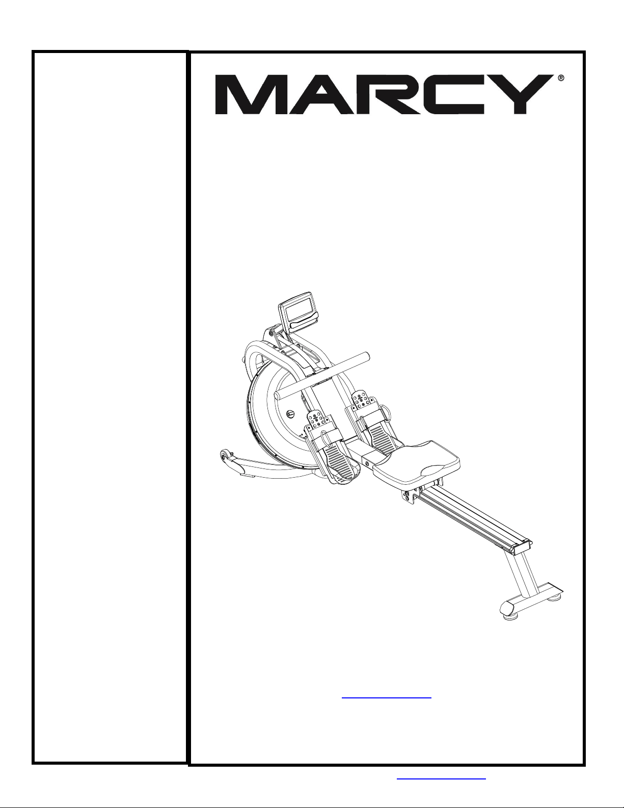
ASSEMBLY &
OWNER'S
MANUAL
Marcy Pro
Water-Resistance
Rower
NS-6023RW
IMPEX® INC.
2801 S. Towne Ave, Pomona, CA 91766
Tel: (800) 999-8899 Fax: (626) 961-9966
www.marcypro.com
suppor[email protected]om

1
© IMPEX INC. www.marcypro.com
TABLE OF CONTENTS
BEFORE YOU BEGIN
1
IMPORANT SAFETY NOTICES
2
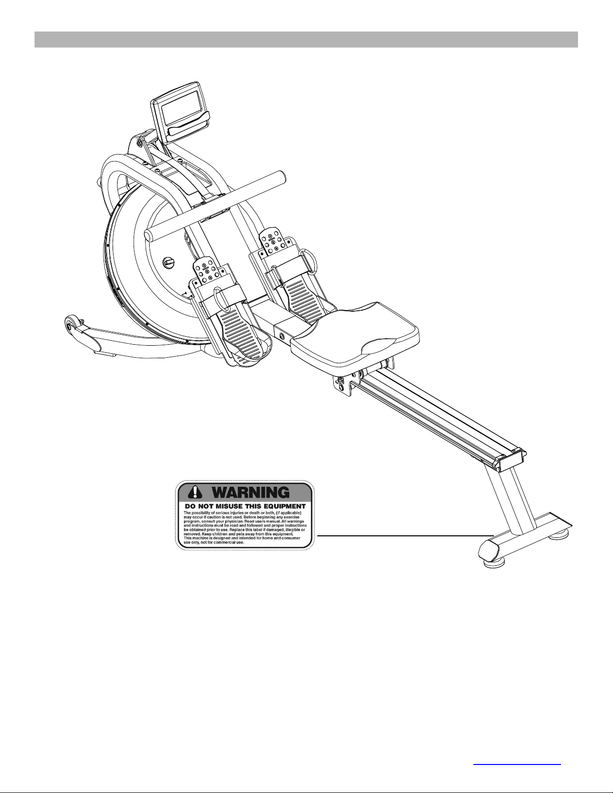
WARNING LABEL PLACEMENT
3
HARDWARE PACK
4
ASSEMBLY INSTRUCTION
5
EXPLODED DIAGRAM
9
PARTS LIST
10
CARE AND MAINTANENCE
13
OPERATING NOTES
14
ADJUSTMENT GUIDE
15
STORAGE GUIDE
16
COMPUTER
17
EXERCISE GUIDELINES
21
WARRANTY
23
ORDERING PARTS
23
BEFORE YOU BEGIN
Thank you for selecting the MARCY Water-Resistance Rower NS-6023RW by IMPEX®
INC. For your safety and benefit, read this manual carefully before using the bike. As a
manufacturer, we are committed to provide you complete customer satisfaction. If you
have any questions, or find there are missing or damaged parts, we guarantee you
complete satisfaction through direct assistance from our factory. To avoid unnecessary
delays, please call our TOLL-FREE customer service number. Our Customer Service
Agents will provide immediate assistance to you.
Toll-Free Customer Service Number
1-800-999-8899
Mon. - Fri. 9 a.m. - 5 p.m. PST
www.marcypro.com

2
© IMPEX INC. www.marcypro.com
IMPORTANT SAFETY NOTICE
PRECAUTIONS
This exercise machine is built for optimum safety. However, certain precautions apply
whenever you operate a piece of exercise equipment. Be sure to read the entire manual
before you assemble or operate your machine. In particular, note the following safety
precautions:
1. Keep children and pets away from the machine at all times. DO NOT leave children
unattended in the same room with the machine.
2. Only one person at a time should use the machine.
3. If the user experiences dizziness, nausea, chest pain, or any other abnormal symptoms,
STOP the workout at once. CONSULT A PHYSICIAN IMMEDIATELY.
4. Position the machine on a clear, leveled surface. DO NOT use the machine near water or
outdoors.
5. Keep hands away from all moving parts.
6. Always wear appropriate workout clothing when exercising. DO NOT wear robes or other
clothing that could become caught in the machine. Running or aerobic shoes are also
required when using the machine.
7. Use the machine only for its intended use as described in this manual. DO NOT use
attachments not recommended by the manufacturer.
8. Do not place any sharp object around the machine.
9. Disabled person should not use the machine without a qualified person or physician in
attendance.
10. Before using the machine to exercise, always do stretching exercises to properly warm up.
11. Never operate the machine if the machine is not functioning properly.
12. Read all warnings posted on the exercise bike.
13. Inspect the exercise bike for worn or loose component prior to use. Tighten/replace any
loose or wore components prior to use.
14. Care should be taken in mounting or dismounting the exercise bike.
15. This exercise bike is for consumer and home use only.
WARNING: BEFORE BEGINNING ANY EXERCISE PROGRAM, CONSULT YOUR
PHYSICIAN. THIS IS ESPECIALLY IMPORTANT FOR INDIVIDUALS OVER THE AGE OF
35 OR PERSONS WITH PRE-EXISTING HEALTH PROBLEMS. READ ALL
INSTRUCTIONS BEFORE USING ANY FITNESS EQUIPMENT. IMPEX INC. ASSUMES NO
RESPONSIBILITY FOR PERSONAL INJURY OR PROPERTY DAMAGE SUSTAINED BY
OR THROUGH THE USE OF THIS PRODUCT.
SAVE THESE INSTRUCTIONS.

5
© IMPEX INC. www.marcypro.com
ASSEMBLY INSTRUCTION
Tools Required for Assembling the Machine: One Crossing Wrench and Allen Wrench,
provided by manufacturer.
NOTE: It is strongly recommended that two or more people assemble this machine to
avoid possible injury.
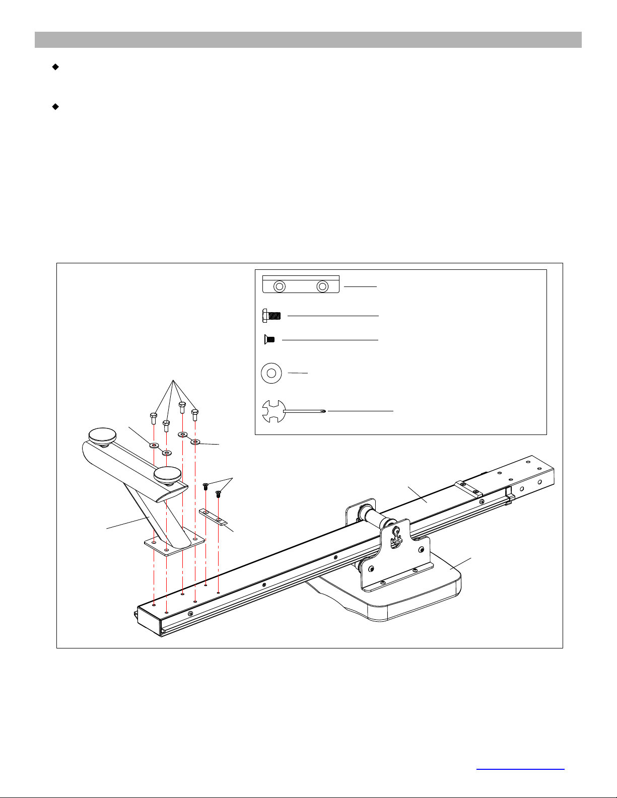
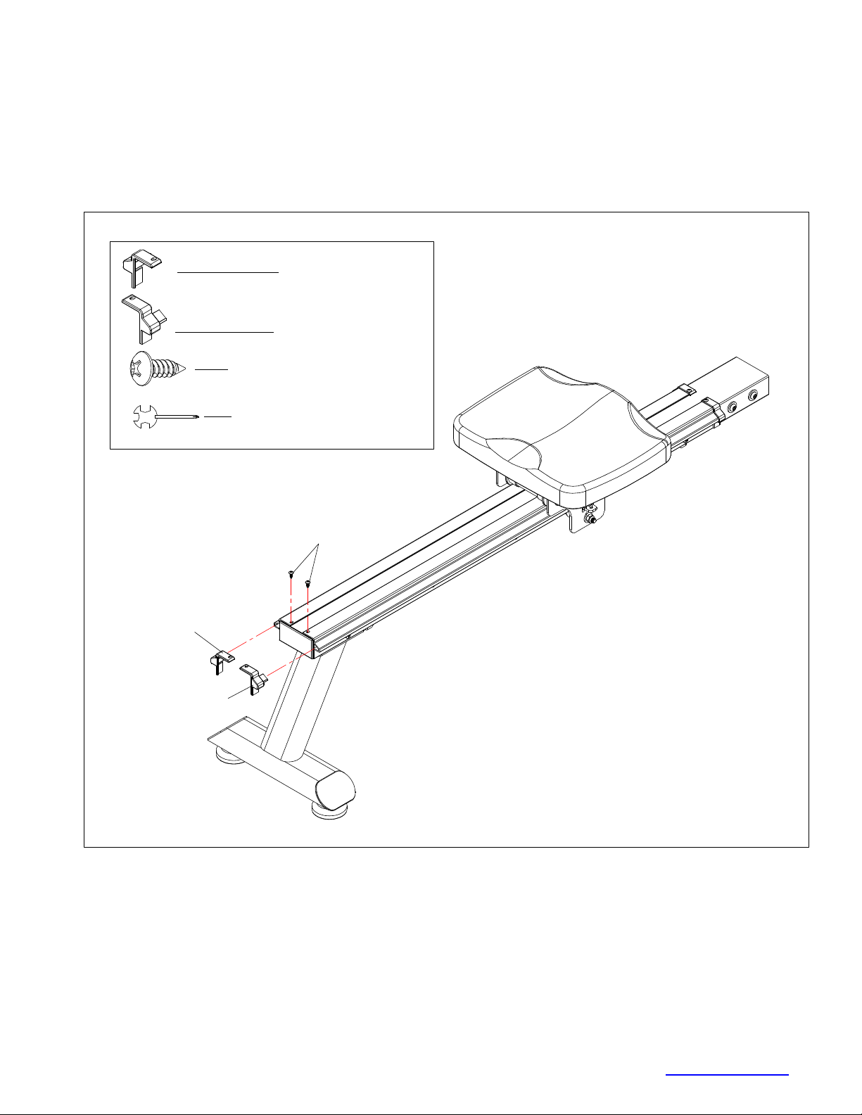
STEP-1
1. Flip the Slide Rail (No. 3) and Seat (No. 38) up-side-down as shown below.
2. Slide the Seat (No. 38) onto the Slide Rail (No. 3). Secure the Limiter Pad (No. 40) with 2
Philips Screws (No. 72).
3. Attach the Rear Stabilizer (No. 2) to the Slide Rail (No. 3) with 4 Washers (No. 74) and 4
Hex Bolt (No. 59). Tighten with Multi-Tool (No. 94).
# 72 M6 x ⅓” 2pcs
#74 Φ ¾" 4pcs
# 59 M8 x ⅔" 4pcs
# 94 S13-17 1pc
2
3
38
40
72
74
59
74
#40 1pc
.
.
7
© IMPEX INC. www.marcypro.com
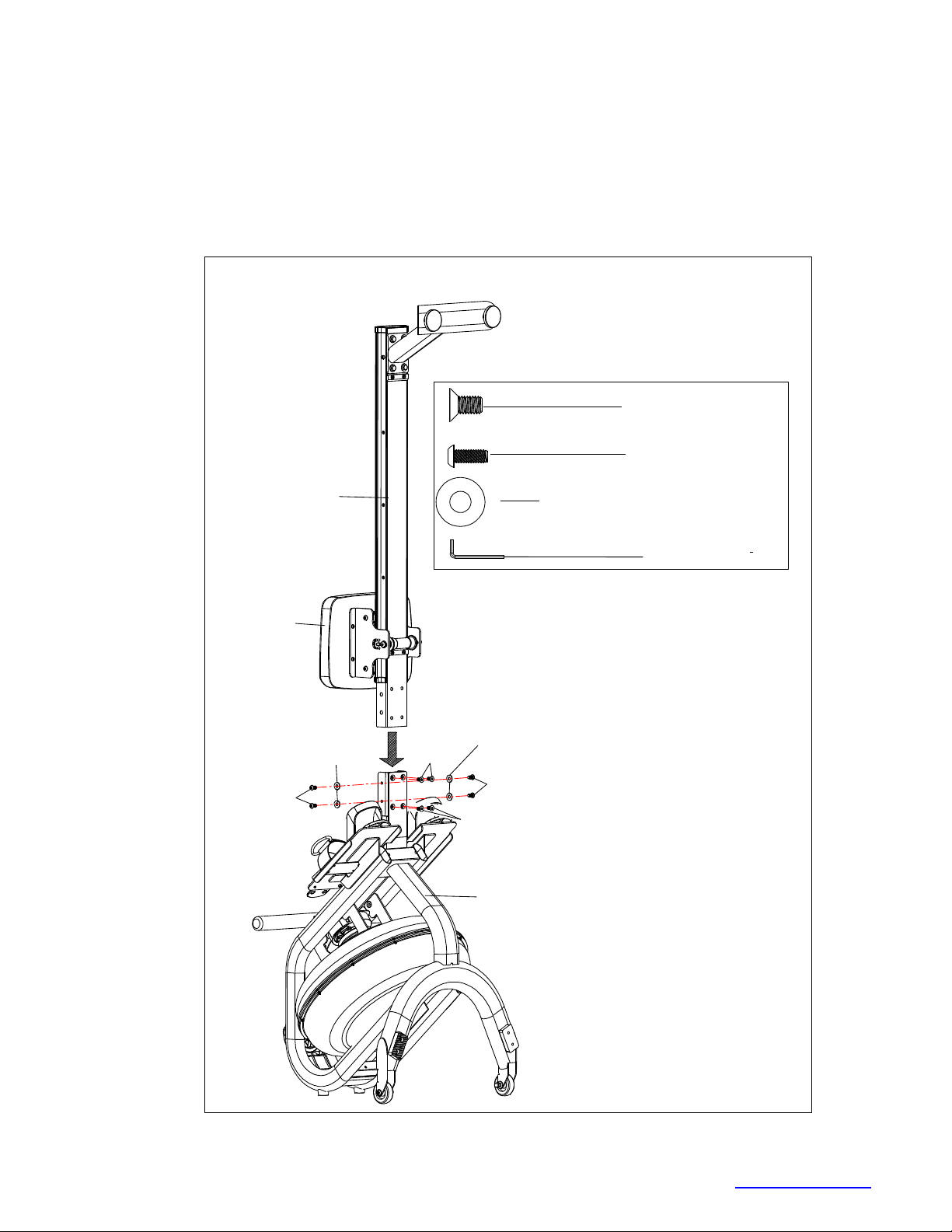
STEP-3
NOTE: Move the Seat (No. 38) to the front of the Slide Rail (No. 3) before assembly to prevent it
from sliding down during assembly.
1. Attach the Slide Rail (No. 3) to the Main Frame (No. 1) using 4 Washers (No. 74), 4 Allen Bolts
(No. 68) and 4 Flat Head Allen Bolts (No. 62).
2. Thread all 8 bolts partially into the holes first, and then tighten with Allen Wrench (No. 93).
62
38
3
1
#93 S5 1pc
#62 M8 x ⅔"4pcs
#68 M8 x ⅔” 4pcs
#74 Φ ¾" 4pcs
62
74
74
68
68
8
© IMPEX INC. www.marcypro.com
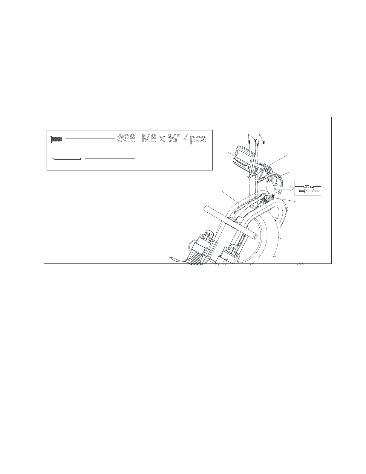
STEP-4
1. Connect the Connection wire (No. 99) to the Sensor wire (No. 56).
2. Plug the Front Decorate cover (No. 26F) into the hole of Main Frame (No. 1).
3. Attach the Support for computer (#54) to Main Frame, Tighten with 4 Screws (#68).
1
54
#68 M8 x ⅔" 4pcs
#93 S5 1pc
68 68
26F
99
56
9
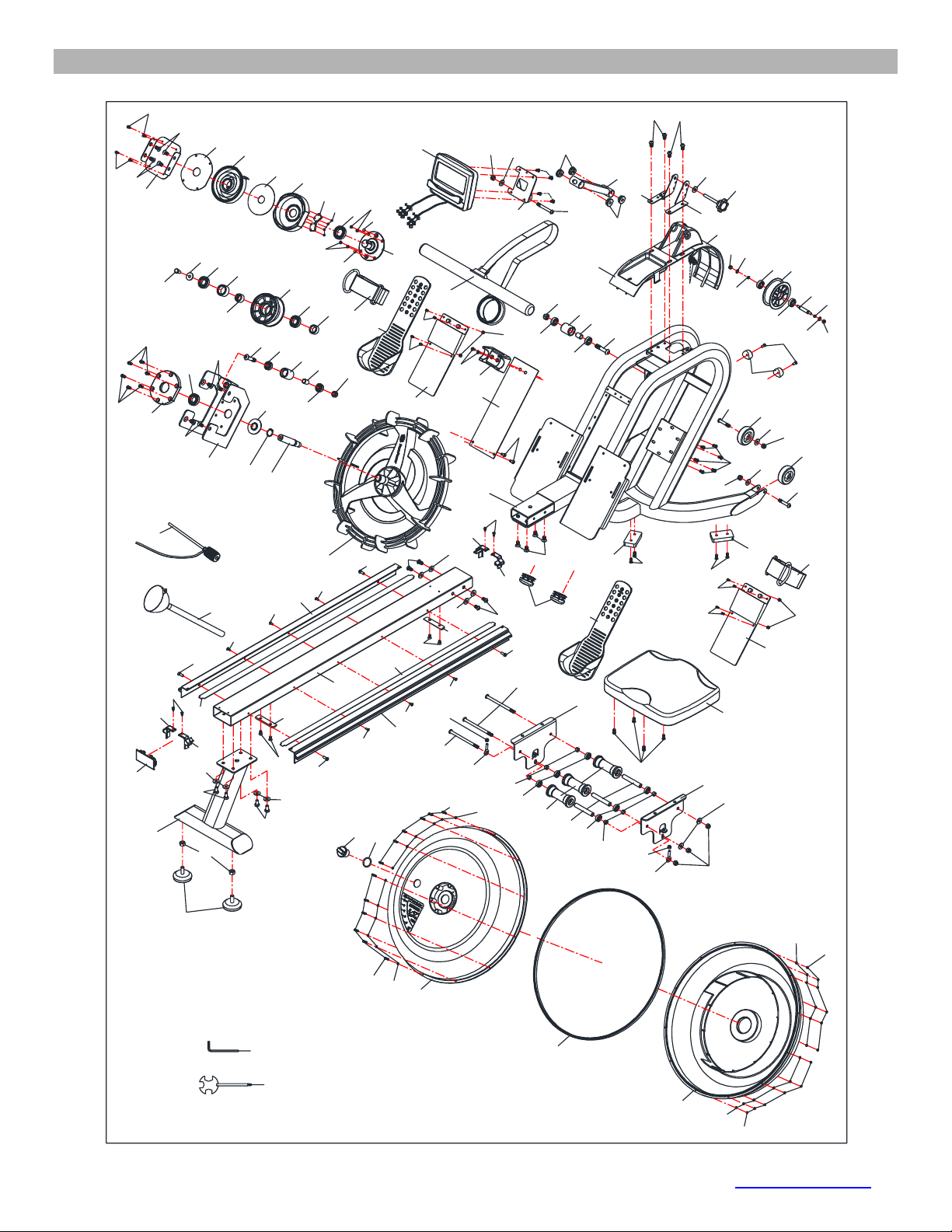
© IMPEX INC. www.marcypro.com
EXPLODED DIAGRAM
52
1
2
3
4
6
6
9
10
11
12
14
15
16
16 17
17
18
18
21
25
24
26R
27
28
29
30
31
36 37
37
38
39
40
40
41
41
42
42
42
42
42
42
43
44
45
45
45
48
50
51
51
73
74
74
74
74
74
74
74
74
68
68
75
75
77 77
100
100
100
79
79
80
22
81
81
81
81
83
83
84
53
69
95
26F
57
58
59
59
59
60
62
62
62
63
63
64
64
65
65
65
65
65 65
66
68 68
65
65
70
71
71
72
72
84
84
84
85
85
86
88
88
90
90
91
92
93
94
28
29
67
67
67
67
82
82
19
20
20
19
61
61
89
89
96
96
69
69
69
69
23
58
58
58
58
58
54
97
5
32
33
34
35
46
47
56
61
61
62
62
55
55
76
76
98
98
99
13
49
87
7
8
74 78

10
© IMPEX INC. www.marcypro.com
NS-6023RW PARTS LIST
No.
Description
Size
Qty.
1
Main frame
1
2
Rear stabilizer
1
3
Slide rail
1
4
Handlebar
1
5
Spring Fixed Plate
1
6
Seat carriage
2
7
Sensor stand L
1
8
Sensor stand R
1
9
Support for computer
1
10
Tank plate
1
11
Support Plate
1
12
Plastic Impeller
1
13
Impeller shaft
1
14
Belt wheel shaft
1
15
Belt wheel
1
16
Guide roller
2
17
Guide roller spacer
2
18
Transport Wheel
2
19
Left Decorative Cover for Rail
2
20
Right Decorative Cover for Rail
2
21
Oval plug
2
22
Rail End Cap
1
23
Level Adjustment Knob
2
24
Upper Tank
1
25
Lower Tank
1
26F/R
Decorate Cover
1
27
Handlebar Seat
1
28
Pedal Support
2

11
© IMPEX INC. www.marcypro.com
29
Pedal Adjustment Sleeve
2
30
Bearing Seat
1
31
Mesh Belt Wheel
1
32
Axle for Volute Spring
1
33
Base of Volute Spring
1
34
PC Board
1
35
Outer PC Board
1
36
Spacer for Mesh Belt Wheel
1
37
Pedal Strap
2
38
Seat
1
39
Seat Roller
3
40
Limiter Pad
2
41
Bearing
6
42
Bearing
6
43
One-way Bearing
1
44
Steel Sleeve
1
45
Bearing
3
46
Bearing
1
47
Volute Spring
1
48
Rubber Sealing Ring
1
49
Seal
1
50
Tank Fill Plug
1
51
Skid Pad
2
52
Funnel
1
53
Pumping Siphon
1
54
Computer
1
55
Magnet
2
56
Square Sensor Wire
1
57
Philips Screw
ST3 x 10
4
58
Flat Head Philips Screw
M4 x ½”
6

12
© IMPEX INC. www.marcypro.com
59
Hex Bolt
M8 x ⅔"
5
60
Allen Bolt
M8 x 5½”
2
61
Philips Screw
M4 x ½”
8
62
Flat Head Allen Bolt
M8 x ⅔"
12
63
Allen Bolt
M8 x 1¾”
2
64
Allen Bolt
M10 x 2"
2
65
Allen Bolt
M6 x ⅔"
24
66
Allen Bolt
M8 x 2½”
1
67
Cross Screw
M5 x ⅔"
8
68
Allen Bolt
M8 x ⅔"
8
69
Philips Screw
M6 x ⅔"
6
70
Allen Bolt
M8 x 5¾”
1
71
Eyebolt
M6 x 1⅛”
2
72
Philips Screw
M6 x ⅓”
4
73
Washer
Φ 1"
1
74
Washer
Φ ¾"
14
75
Washer
Φ ½”
2
76
Philips Screw
ST5 x 10
4
77
Belt wheel spacer
2
78
Adjustment Knob
1
79
Aircraft Nut
M10
2
80
Aircraft Nut
M8
3
81
Aircraft Nut
M6
4
82
Aircraft Nut
M5
4
83
Philips Screw
M3*22
12
84
Stainless Washer
M3
24
85
Aircraft Nut
M3
12
86
Main Frame Plate
1
87
C Clip
1
88
Bushing
4

13
© IMPEX INC. www.marcypro.com
89
EVA foam For Rail
2
90
Spacer for Seat Roller
Φ ½”
6
91
Roller tube
3
92
O-Shaped Ring
1
93
Allen Wrench
1
94
Multi-Tool
1
95
Frame Bumper
2
96
Aluminum Rail
2
97
Hex Nut
M10
2
98
Cross Screw
M5 x 10
4
99
Connection Wire
1
100
Acorn Nut
M8
3
CARE AND MAINTENANCE
1. Inspect and tighten all parts each time you use the machine. Replace any worn parts
immediately.
2. This machine can be cleaned using a damp cloth and mild non-abrasive detergent. Do not use
solvents.
3. Store the rower IN-DOOR. Excess moisture and water would cause rust on the frame.
4. The rower shall be placed at least 24 inches away from the wall or/and any other object such as
furniture to provide safe access to and passage around the machine.
5. To avoid possible injury, the help of two or more people are needed when moving the machine
around.
6. Disposal Instructions – The equipment can be safely disassembled and disposed without
unreasonable hazards. Call your local recycle agency regarding details of recycling.
7. The maximum user weight is 300 lbs.
8. Assembled Dimension (L x W x H): 77” x 19” x 36”
14
© IMPEX INC. www.marcypro.com
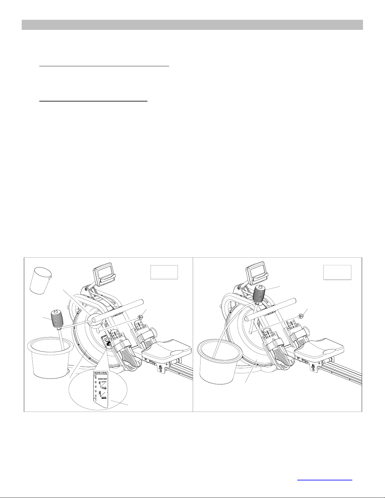
OPERATING NOTES
FILLING AND EMPTYING THE WATER TANK
1. Remove the Tank Fill Plug (No.50) from the Upper Tank Cover (No. 24).
2. To fill the tank with water, refer to Fig. A.
• Insert the Funnel (No. 52) into the tank, then use a cup or the Siphon Pump (No. 53) and
a bucket to fill the tank. Use the water level indicator on the side of the tank to fill to the
desired water level in the tank.
3. To empty the tank, refer to Fig. B.
• Place a bucket next to the rower and use the Siphon Pump (No. 53) to pump out the water
from the tank into the bucket.
4. Re-insert the Fill Plug (No. 50) into the Upper Tank Cover (No. 24) when done. Wipe off excess
water from the frame.
NOTE:
• Fill the tank only with tap water. Never use pool chlorine or chlorine bleach, this will damage the
tank and void the warranty.
• Do not consume the tank water. Dispose the water after pumping it out from the tank.
WATER LEVEL
• See Fig. A. The water level indicator is on the side of the tank. The maximum fill level is 6.
Never fill it over this limit. Filling the tank over this limit will void the warranty.
• The resistance depends on the water level in the tank. Water level 1 is the lowest resistance. Level
6 is the highest resistance.
50
53
52
24
Fig. A Fig. B
Water level label
50
24
53
15
© IMPEX INC. www.marcypro.com
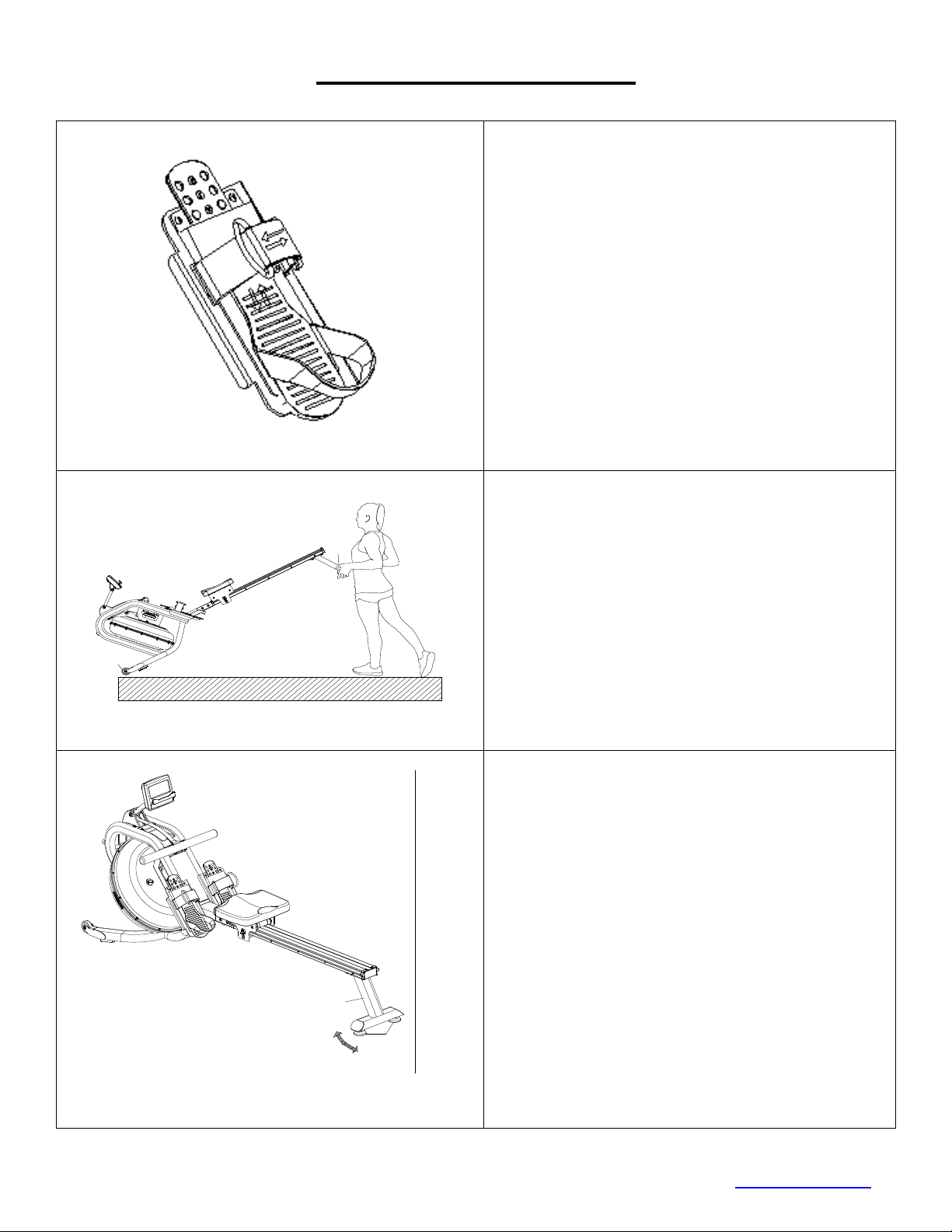
ADJUSTMENT GUIDE
The pedal strap is adjustable and can be
personalized to fit the user’s foot size.
To adjust the pedal strap, remove the Velcro
end of the strap from the mesh side by pulling it
upward then to the left.
Once removed, you may increase the opening
of the pedal strap by pulling the mesh end up
and to the right.
To tighten, pull the Velcro end of the pedal
strap upward then to the right and down to
secure it to the mesh side of the strap.
MOVING THE MACHINE
To move the machine, lift up the Rear Support
(No. 2) until the Transport Wheels (No. 18) on
the front stabilizer touch the ground. With the
wheels on the ground, you can transport the
machine to the desired location with ease.
To Stabilize the Rower
Adjust the Level Adjustment Knob (No. 23)
below the Rear Stabilizer (No.2) of the
machine if the machine is unbalance during
use.
2
18
2
23
16
© IMPEX INC. www.marcypro.com
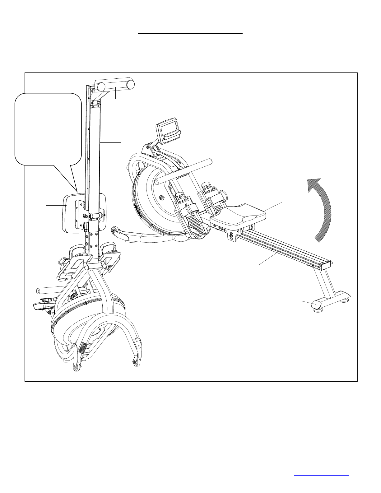
STORAGE GUIDE
Caution!
Moving parts, such as the seat, can cause injury. Keep hands clear of the sliding rail during use!
38
3
2
38
2
3
CAUTION!
Move the Seat (No.
38) to the front of
the Slide Rail (No.
3) prior to lifting the
rower or it will slide
down when raising
the rower for
storage causing
injury.

17
© IMPEX INC. www.marcypro.com
COMPUTER
Power on
The full LCD display will be shown 2 seconds after the installation of batteries. It will
then enter the workout intensity selection mode (L1 to L6): press to select the
Level then press Enter to confirm and enter into standby mode.
BUTTONS
RECOVERY:Press this button to test the pulse recovery for 60 seconds, the
computer needs to have the pulse signal input.
RESET:
1. Short press to toggle between parameter setting mode and program selection mode.
2. Short press to return to standby mode while stopped.
3. Long Press (2 seconds) and the computer will reset to default values.
START/STOP:To start or pause the session.
ENTER:
1. Confirms program selection.
2. Confirms parameter selection and moves to the next parameter selection.
3. Press it to switch the function value display during the training.
Left Arrow :
1. Increases the setting parameter Increase the setting parameter
2. Cycle through the PROGRAM (QUICK、STANDARD、TARGET SINGLE、TARGET
INTERVALS、CUSTOM、RACE) selections.
Right Arrow :
1. Decreases the setting parameter.
2. Cycle through the PROGRAM (QUICK、STANDARD、TARGET SINGLE、
TARGET INTERVALS、CUSTOM、RACE) selections.
Note: Press to display the function value in the large middle display
window.

18
© IMPEX INC. www.marcypro.com
Note:TIME and DISTANCE cannot be set together, you will need to choose TIME or
DISTANCE to set.
DISPLAY
TIME: Displays the duration.
TIME/500M: The average 500-meter time will automatically be displayed and
continuously updated.
SPM: Strokes per minute.
DISTANCE: Displays the distance.
STROKES: Displays the current strokes.
TOTAL STROKE: Displays the accumulated total strokes.
CALORIES: Displays the calories.
PULSE: Displays user’s heart rate during training.
DRAG FORCE: Displays the current drag force.
WATT: Displays the current watt.
A+: Displays the average function value of time, calories, watt and pulse.
OPERATION
QUICK START:Press to select Quick Start then press START/STOP to start
the training.
1. Press ENTER to switch the function value to from the smaller window to be displayed
in the larger middle display during the training.
2. The program profile displays 16 columns, with each column equaling to 100 meter.
STANDARD:Press to select STANDARD then press ENTER to confirm and
enter to select one of five training modes: 2000m, 5000m, 10000m, 30:00,
500m/1:00. Press START/STOP to start the program. The preset value will count
down, other values will count up. Press RESET to go back to standby mode when
the preset function value counts down to zero.
TARGET SINGLE:Press to select TARGET SINGLE then press ENTER to
confirm and enter one of four training modes: Single Time, Single Distance, Single
Calories, Single THR
1. Single Time: Set the time; press START/STOP to start the training after setting
desired time.
2. Single Distance: Set the distance; press START/STOP to start the training after
setting the desired distance.
3. Single Calories: Set the calories; press START/STOP to start the training after setting
the desired calories.
4. Single T.H.R: Set the Targeted Heart Rate from 90 to 200 bpm, press START/STOP
to start the training after setting the desired THR.
default
Increment
Decrement
Setting Range
Display Range
TIME
0:00
±1
0:00~99:00
0:00~99:59
DISTANCE
0
±100
0~99900
0~99999
STROKES
0
±10
0~99990
0~99999
CALORIES
0
±10
0~9990
0~9999

19
© IMPEX INC. www.marcypro.com
Alarm will sound when the current heart rate is higher than THR.
TARGET INTERVALS:Press to select TARGET INTERVAL then press
ENTER to confirm and enter one of three Intervals setting modes: Intervals
Time, Intervals Distance and Intervals Variable.
1. Intervals Time: Press to set the training time then press ENTER to confirm
and set the REST TIME. Press START/STOP to start the training after setting
desired time.
2. Intervals Distance: Press to set the training distance then press ENTER to
confirm and set the REST TIME. Press START/STOP to start the training when
done.
3. Intervals Variable: Press to set the training time then press ENTER to
confirm and set the training distance. Press ENTER to confirm and set the REST
TIME then press START/STOP to start the training when done.
CUSTOM:Press to select CUSTOM then press ENTER to confirm and one of
four Custom modes: V 00:30/00:30R, V1:00/1:00R-7, V2000m/3:00R-4,
V1:40/:20R.
1. V :30/:30R:Training 30 seconds,rest 30 seconds.
2. V1:00/1:00R-7:Training one minute, rest one minute, repeat 7 times.
3. V2000m/3:00R-4:Training 2000m, rest three minutes, repeat 4 times.
4. V1:40/:20R:Training one minute forty seconds, rest 20 seconds, repeat 9 times.
RACE:Press to select RACE then press ENTER to confirm then press to
select L1 through L15. Press ENTER to confirm and enter DISTANCE setting;
DISTANCE will blink then press UP or DOWN to adjust. Press START/STOP to
begin/pause training.
• The screen will show U (user) and PC (competitor simulation) for the race.
• Once PC or User reach the end of training, the computer will stop.
• When the race is complete, you can cycle through the smaller display windows to
see: TIME, SPM, DISTABCE, STROKES, CALOGIES, and PULSE.
• You can also press ENTER to change the display to show: TIME/500M, TOTAL
STROKES, and WATT.
NOTE: in the RACE PROGRAM only the DISTANCE can be set, the
TIME/500M is fixed. See below table for the TIME/500M for L1-L15:
L1
8:00
L6
5:30
L11
3:00
L2
7:30
L7
5:00
L12
2:30
L3
7:00
L8
4:30
L13
2:00
L4
6:30
L9
4:00
L14
1:30
L5
6:00
L10
3:30
L15
1:00

20
© IMPEX INC. www.marcypro.com
RECOVERY
1. This computer works with a 5.3 KHz chest strap heart rate monitor (not included).
After exercising for a period of time, while wearing the chest strap monitor, press the
“RECOVERY” button. All function displays will stop except “TIME”. It will start to
count down from 00:60 to 00:00.
2. Screen will display your heart rate recovery status with the F1, F2….to F6.
3. F1 is outstanding, F6 is poor. User may keep exercising to improve the heart rate
recovery status. (Press the RECOVERY button again to return the main display.)
Note:
1. The computer will enter sleep mode after 4 minutes of inactivity and all the value will
reset to zero automatically except TOTAL STROKES. Start training or press any
button to wake up the computer.
2. If the computer displays abnormally, please re-install the battery and try again after
15 seconds.
3. Battery Spec: AA (2PCS). The batteries must be removed from the computer before
the rower is disposed, and the batteries should be disposed according to local laws
and regulations.
4. Do not dispose of electrical appliances as unsorted municipal waste, use separate
collection facilities.
5. Contact your local government for information regarding the collection systems
available.
6. If electrical appliances are disposed of in landfills or dumps, hazardous substances
can leak into the groundwater and get into the food chain, damaging your health and
well-being.
7. When replacing old appliances with new once, the retailer is legally obligated to take
back your old appliance for disposal at least for free of charge.
21
© IMPEX INC. www.marcypro.com
EXERCISE GUIDELINES
Using your MAGNETIC ROWER
will provide you with several benefits, it will improve
your physical fitness, tone muscle and in conjunction with calorie-controlled diet help
you lose weight.
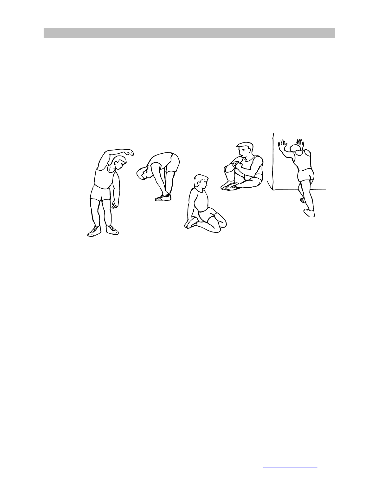
1. The Warmup Phase
This stage helps get the blood flowing around the body and the muscles working
properly. It will also reduce the risk of cramp and muscle injury. It is advisable to do a
few stretching exercises as shown below. Each stretch should be held for approximately
30 seconds, do not force or jerk your muscles into a stretch - if it hurts, STOP.
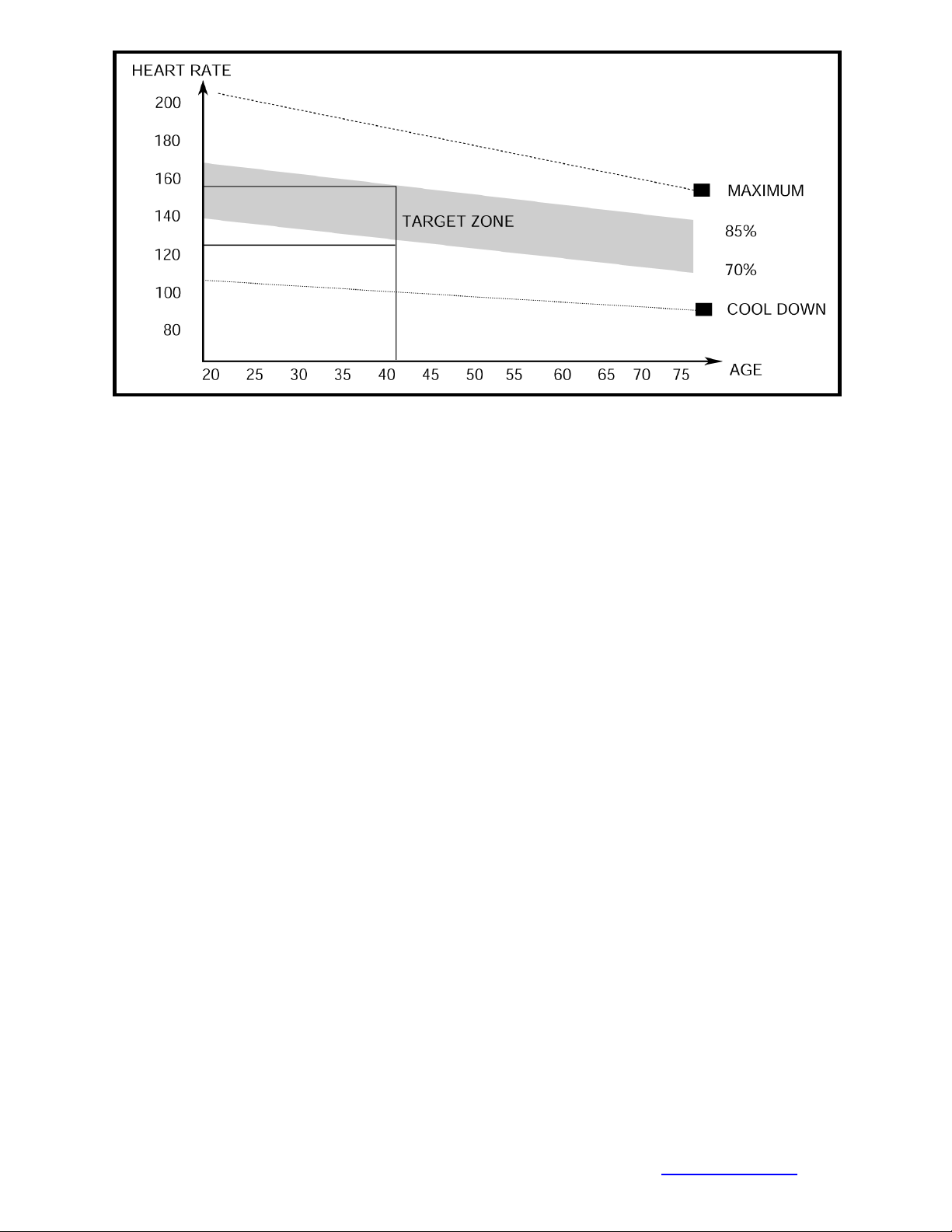
2. The Exercise Phase
This is the stage where you put the effort in. After regular use, the muscles in your legs
will become more flexible. Work to your targeted heart rate but it is very important to
maintain a steady tempo throughout. The rate of work should be sufficient to raise your
heartbeat into the target zone shown on the graph below.
SIDE BENDS OUTER THIGH
INNER THIGH
FORWARD
BENDS
CALF / ACHILLES
22
© IMPEX INC. www.marcypro.com
This stage should last for a minimum of 12 minutes though most people start at
about 15-20 minutes
3. The Cool Down Phase
This stage is to let your Cardio-vascular System and muscles wind down. This is a
repeat of the warm up exercise e.g. reduce your tempo, continue for approximately 5
minutes. The stretching exercises should now be repeated, again remembering not to
force or jerk your muscles into the stretch.
As you get fitter you may need to train longer and harder. It is advisable to train at least
three times a week, and if possible space your workouts evenly throughout the week.
MUSCLE TONING
To tone muscle while on your MAGNETIC ROWER you will need to have the resistance
set quite high. This will put more strain on our leg muscles and may mean you cannot
train for as long as you would like. If you are also trying to improve your fitness you
need to alter your training program. You should train as normal during the warm up and
cool down phases, but towards the end of the exercise phase you should increase
resistance making your legs work harder. You will have to reduce your speed to keep
your heart rate in the target zone.
WEIGHT LOSS
The important factor here is the amount of effort you put in. The harder and
longer you work the more calories you will burn. Effectively this is the same as if
you were training to improve your fitness, the difference is the goal.

23
© IMPEX INC. www.marcypro.com
IMPEX® INC.
LIMITED WARRANTY
IMPEX Inc. ("IMPEX®") warrants this product to be free from defects in workmanship and material, under
normal use and service conditions, for a period of two years on the Frame from the date of purchase. This
warranty extends only to the original purchaser. IMPEX's obligation under this Warranty is limited to
replacing or repairing, at IMPEX's option.
All returns must be pre-authorized by IMPEX. Pre-authorization may be obtained by calling IMPEX
Customer Service Department at 1-800-999-8899. All freights for products return to IMPEX must be prepaid
by the customer. This warranty does not extend to any product or damage to a product caused by or
attributable to freight damage, abuse, misuse, improper or abnormal usage or repairs not provided by an
IMPEX authorized service center or for products used for commercial or rental purposes. No other warranty
beyond that specifically set forth above is authorized by IMPEX.
IMPEX is not responsible or liable for indirect, special or consequential damages arising out of or in
connection with the use or performance of the product or other damages with respect to any economic loss,
loss of property, loss of revenues or profits, loss of enjoyments or use, costs of removal, installation or other
consequential damages or whatsoever natures. Some states do not allow the exclusion or limitation of
incidental or consequential damages. Accordingly, the above limitation may not apply to you.
The warranty extended hereunder is in lieu of any and all other warranties and any implied warranties of
merchantability or fitness for a particular purpose is limited in its scope and duration to the terms set forth
herein. Some states do not allow limitations on how long an implied warranty lasts. Accordingly, the above
limitation may not apply to you.
This warranty gives you specific legal right. You may also have other rights which vary from state to state.
Register on-line www.marcypro.com
IMPEX® INC.
2801 S. Towne Ave.
Pomona, CA 91766
ORDERING REPLACEMENT PARTS
Replacement parts can be ordered by calling our Customer Service Department toll-free at 1-800-999-8899
during our regular business hours: Monday through Friday, 9 am until 5 pm Pacific standard time.
When ordering replacement part, always give the following information.
1. Model
2. Description of Parts
3. Part Number
4. Date of Purchase