
User Guide
HP Thin Client

© Copyright 2019 HP Development Company,
L.P.
DisplayPort™, the DisplayPort™ logo, and
VESA® are trademarks or registered
trademarks owned by the Video Electronics
Standards Association (VESA) in the United
States and other countries. Linux is the
registered trademark of Linus Torvalds in the
U.S. and other countries. Microsoft and
Windows are either registered trademarks or
trademarks of Microsoft Corporation in the
United States and/or other countries.
The information contained herein is subject to
change without notice. The only warranties for
HP products and services are set forth in the
express warranty statements accompanying
such products and services. Nothing herein
should be construed as constituting an
additional warranty. HP shall not be liable for
technical or editorial errors or omissions
contained herein.
Second Edition: November 2019
First Edition: July 2019
Document Part Number: L63760-002
Product Notice
This user guide describes features that are
common to most models. Some features may
not be available on your computer.
Not all features are available in all editions or
versions of Windows. Systems may require
upgraded and/or separately purchased
hardware, drivers, software or BIOS update to
take full advantage of Windows functionality.
Windows 10 is automatically updated, which is
always enabled. ISP fees may apply and
additional requirements may apply over time
for updates. See http://www.microsoft.com.
To access the latest user guides, go to
http://www.hp.com/support, and follow the
instructions to nd your product. Then select
User Guides.
Software terms
By installing, copying, downloading, or
otherwise using any software product
preinstalled on this computer, you agree to be
bound by the terms of the HP End User License
Agreement (EULA). If you do not accept these
license terms, your sole remedy is to return the
entire unused product (hardware and software)
within 14 days for a full refund subject to the
refund policy of your seller.
For any further information or to request a full
refund of the price of the computer, please
contact your seller.

About This Guide
WARNING! Indicates a hazardous situation that, if not avoided, could result in serious injury or death.
CAUTION: Indicates a hazardous situation that, if not avoided, could result in minor or moderate injury.
IMPORTANT: Indicates information considered important but not hazard-related (for example, messages
related to property damage). Warns the user that failure to follow a procedure exactly as described could
result in loss of data or in damage to hardware or software. Also contains essential information to explain a
concept or to complete a task.
NOTE: Contains additional information to emphasize or supplement important points of the main text.
TIP: Provides helpful hints for completing a task.
iii

iv About This Guide

Table of contents
1 Hardware Reference ...................................................................................................................................... 1
Product features .................................................................................................................................................... 1
Components ........................................................................................................................................ 1
Certicates, labels, and serial number location ................................................................................. 2
Setup ...................................................................................................................................................................... 3
Warnings and cautions ........................................................................................................................ 3
Installing the stand .............................................................................................................................. 3
Installing a security cable .................................................................................................................... 6
Mounting and orienting the thin client ............................................................................................... 6
Supported orientation and placement ............................................................................. 9
Unsupported placement ................................................................................................. 11
Connecting the AC adapter and power cord ...................................................................................... 12
Routine thin client care ..................................................................................................................... 12
2 Hardware Changes ....................................................................................................................................... 13
Warnings and cautions ........................................................................................................................................ 13
Removing and replacing the access panel .......................................................................................................... 13
Removing the access panel ............................................................................................................... 14
Replacing the access panel ............................................................................................................... 15
Locating internal components ............................................................................................................................ 16
Removing and replacing the M.2 ash storage module ..................................................................................... 16
Removing and replacing the battery ................................................................................................................... 18
Upgrading system memory ................................................................................................................................. 20
Removing and installing a memory module ..................................................................................... 21
Replacing a WLAN card ........................................................................................................................................ 23
3 Troubleshooting .......................................................................................................................................... 25
Computer Setup (F10) Utility, BIOS Settings ....................................................................................................... 25
Computer Setup (F10) Utility ............................................................................................................ 25
Using Computer Setup (F10) Utility ................................................................................ 26
Computer Setup—File .................................................................................................... 27
Computer Setup—Storage ............................................................................................. 28
Computer Setup—Security ............................................................................................. 29
Computer Setup—Power ................................................................................................ 30
Computer Setup—Advanced .......................................................................................... 31
Changing BIOS Settings from the HP BIOS Conguration Utility (HPBCU) .......................................................... 32
v

Updating or restoring a BIOS ............................................................................................................................... 35
Updating the rmware for Wake-On-Specic-Key .............................................................................................. 36
Diagnostics and troubleshooting ........................................................................................................................ 36
Lights ................................................................................................................................................. 36
Wake-on LAN ....................................................................................................................................................... 36
Power-on sequence ............................................................................................................................................. 37
Resetting the setup and power-on passwords ................................................................................................... 37
Power-on diagnostic tests ................................................................................................................................... 37
Interpreting POST diagnostic front panel lights and audible codes ................................................................... 38
Troubleshooting ................................................................................................................................................... 40
Basic troubleshooting ....................................................................................................................... 40
Diskless (no-ash) thin client troubleshooting ................................................................................ 41
Conguring a PXE server ..................................................................................................................................... 42
Using HP ThinUpdate to restore the image ......................................................................................................... 42
Device management ............................................................................................................................................ 43
Power cord set requirements .............................................................................................................................. 43
Requirements for all countries ......................................................................................................... 43
Requirements for specic countries and regions ............................................................................. 44
Statement of volatility ......................................................................................................................................... 45
Available memory devices ................................................................................................................ 45
Specications ....................................................................................................................................................... 47
4 Using HP PC Hardware Diagnostics ................................................................................................................ 48
Using HP PC Hardware Diagnostics Windows (select products only) ................................................................. 48
Downloading HP PC Hardware Diagnostics Windows ....................................................................... 48
Downloading the latest HP PC Hardware Diagnostics Windows version ....................... 49
Downloading HP Hardware Diagnostics Windows by product name or number
(select products only) ..................................................................................................... 49
Installing HP PC Hardware Diagnostics Windows ............................................................................. 49
Using HP PC Hardware Diagnostics UEFI ............................................................................................................. 49
Starting HP PC Hardware Diagnostics UEFI ....................................................................................... 50
Downloading HP PC Hardware Diagnostics UEFI to a USB ash drive .............................................. 50
Downloading the latest HP PC Hardware Diagnostics UEFI version .............................. 50
Downloading HP PC Hardware Diagnostics UEFI by product name or number
(select products only) ..................................................................................................... 50
Using Remote HP PC Hardware Diagnostics UEFI settings (select products only) ............................................. 51
Downloading Remote HP PC Hardware Diagnostics UEFI ................................................................. 51
Downloading the latest Remote HP PC Hardware Diagnostics UEFI version ................. 51
Downloading Remote HP PC Hardware Diagnostics UEFI by product name or
number ............................................................................................................................ 51
Customizing Remote HP PC Hardware Diagnostics UEFI settings .................................................... 51
vi

Appendix A Electrostatic discharge .................................................................................................................. 53
Preventing electrostatic damage ........................................................................................................................ 53
Grounding methods ............................................................................................................................................. 53
Appendix B Shipping information .................................................................................................................... 54
Shipping preparation ........................................................................................................................................... 54
Important service repair information .................................................................................................................. 54
Appendix C Accessibility ................................................................................................................................. 55
HP and accessibility ............................................................................................................................................. 55
Finding the technology tools you need ............................................................................................ 55
The HP commitment ......................................................................................................................... 55
International Association of Accessibility Professionals (IAAP) ....................................................... 55
Finding the best assistive technology .............................................................................................. 56
Assessing your needs ..................................................................................................... 56
Accessibility for HP products .......................................................................................... 56
Standards and legislation .................................................................................................................................... 57
Standards .......................................................................................................................................... 57
Mandate 376 – EN 301 549 ............................................................................................ 57
Web Content Accessibility Guidelines (WCAG) ................................................................ 57
Legislation and regulations .............................................................................................................. 57
Useful accessibility resources and links .............................................................................................................. 58
Organizations .................................................................................................................................... 58
Educational institutions .................................................................................................................... 58
Other disability resources ................................................................................................................. 58
HP links .............................................................................................................................................. 59
Contacting support .............................................................................................................................................. 59
Index ............................................................................................................................................................. 60
vii

viii
1 Hardware Reference
Product features
For the latest specications or additional specications on this product, go to http://www.hp.com/go/
quickspecs and search for your specic model to nd the model-specic QuickSpecs.
Various options are available for your thin client. For more information about some of the available options,
go to http://www.hp.com and search for your specic model.
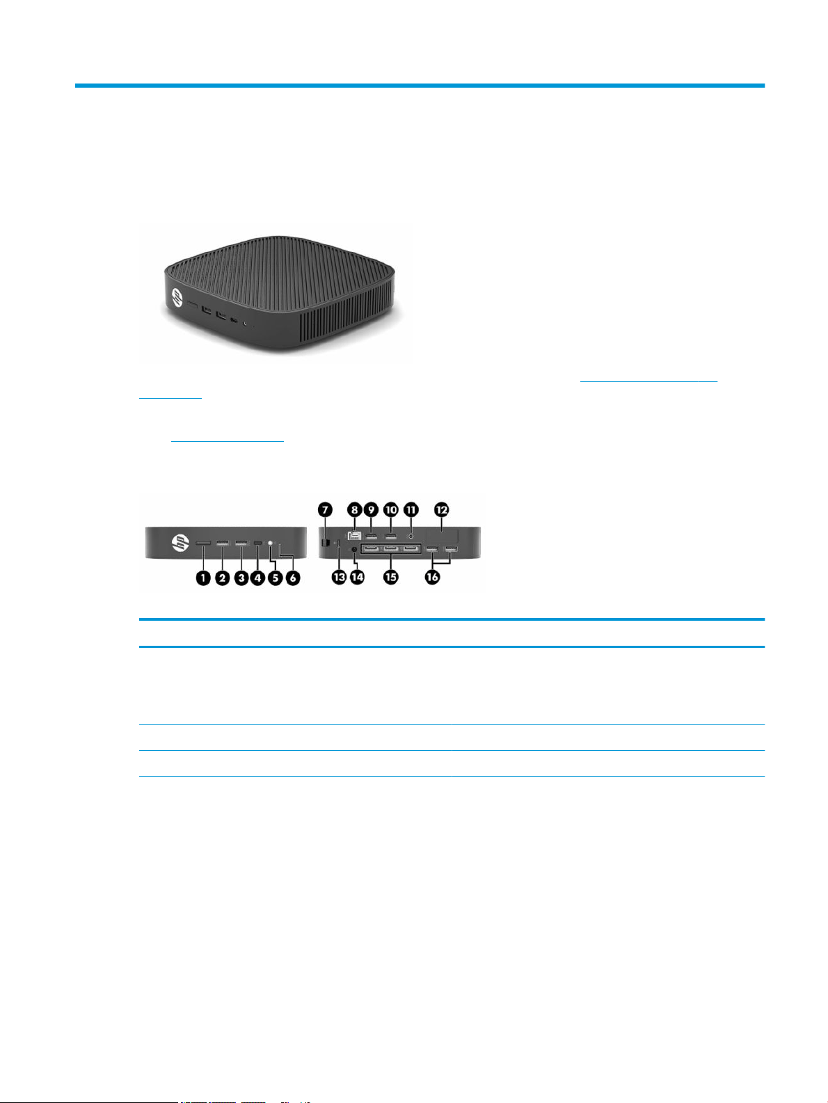
Components
Table
1-1 Components
Components
(1) Power button (9) USB Type-A 2.0 port (designated for Power-on from
Keyboard on select models only)
NOTE: Press alt + P to turn on the thin client from the
keyboard (select models only).
(2) USB Type-A 3.1 Gen 1 port (10) USB Type-A 2.0 port
(3) USB Type-A 3.1 Gen 2 port (11) Audio-out port
(4) USB Type-C 3.1 Gen 2 downstream facing port (DFP) (12) Optional port
● Blank; no option included (shown)
● USB Type-A 3.1 Gen 1 ports (2)
● DisplayPort™ over USB Type-C with USB power
delivery
● HDMI digital video output
● VGA analog video output
● External Wi-Fi antenna connector
● Fiber optic NIC connectors (SC or LC)
Product features 1
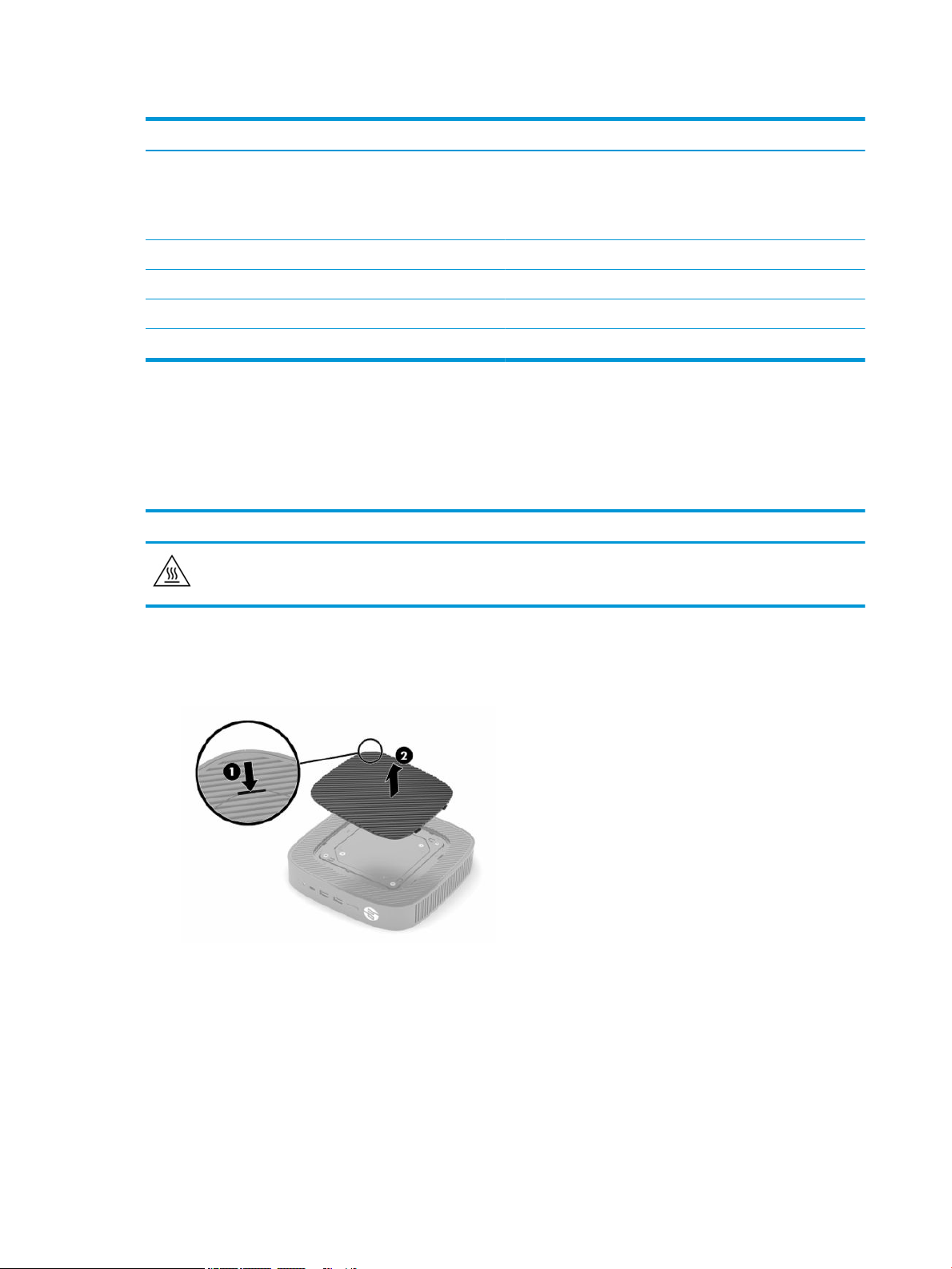
Table 1-1 Components (continued)
Components
● Serial port with congurable power
● Serial ports via cable adapter (2); blue port is a
congurable power port, and black port is a
normal port
(5) Headset jack (13) Cable lock slot
(6) Hard drive activity light (14) Power connector
(7) Rear I/O panel latch (15) DisplayPort connectors (3)
(8) RJ-45 (network) jack (16) USB Type-A 3.1 Gen 1 ports (2)
Certicates, labels, and serial number location
The certicates, labels, and serial number are located under the side cover. Have the serial number available
when contacting HP customer service for assistance.
Table 1-2 Burn hazard warning
Burn hazard warning
If the thin client has been in operation before you remove the side cover, the metal plate underneath the side
cover can reach temperatures that may cause discomfort if directly touched. Turn the thin client o and allow 20
minutes for it to cool to room temperature before you remove the side cover.
1. Lay the thin client down with the left side up and the front side with the HP logo facing you.
2. Insert a ngernail in the slot (1), and then lift the side cover (2) o the thin client.
2 Chapter 1 Hardware Reference
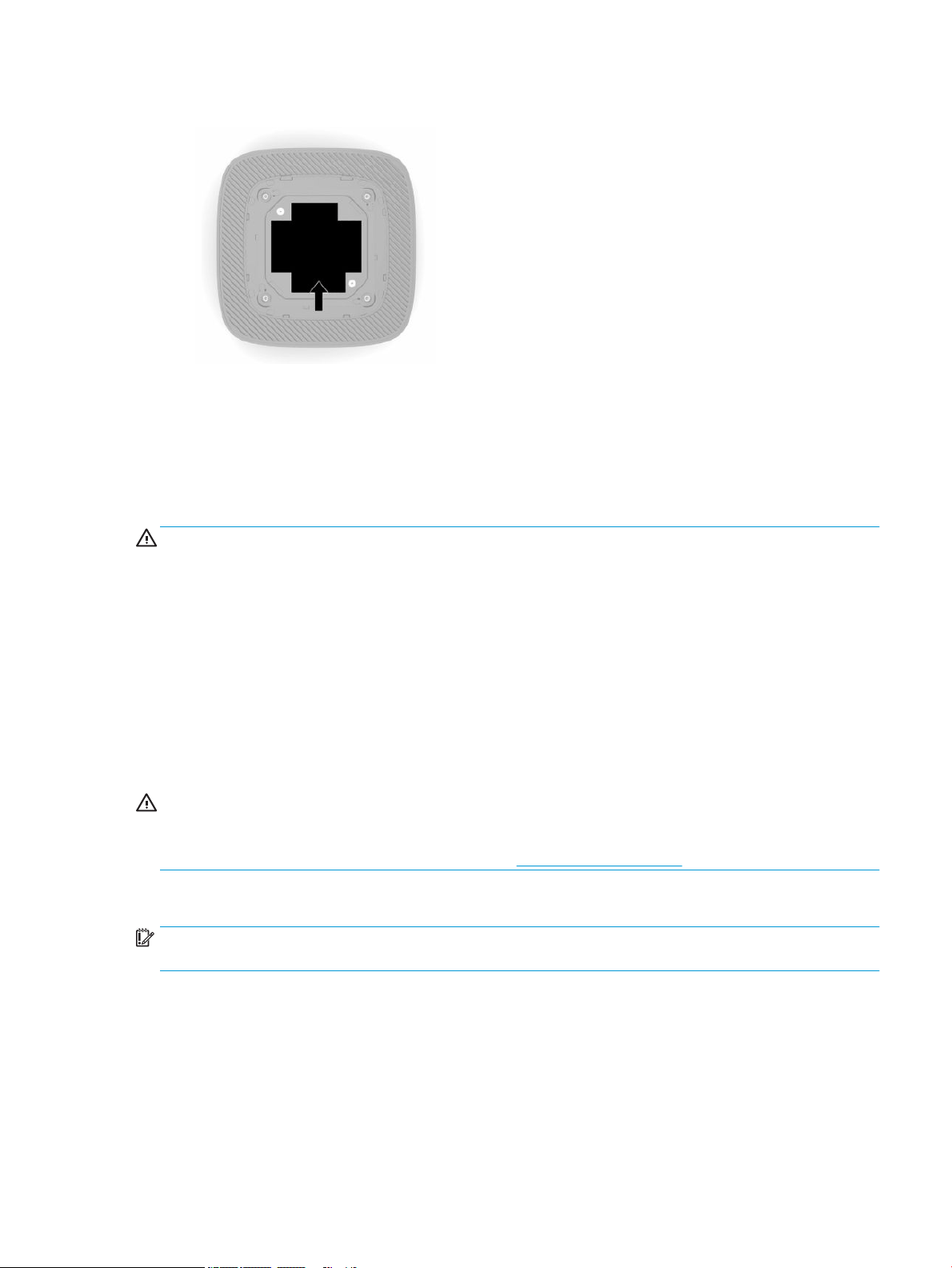
3. Locate the certicates, labels, and serial number as shown in the following illustration.
Setup
Warnings and cautions
Before performing upgrades be sure to carefully read all of the applicable instructions, cautions, and
warnings in this guide.
WARNING! To reduce the risk of personal injury or equipment damage from electric shock, hot surfaces, or
re:
Install the thin client in a location where children are unlikely to be present.
Do not plug telecommunications or telephone connectors into the network interface controller (NIC)
receptacles.
Do not insert objects into or through the system vents.
Plug the power cord into an AC outlet that is easily accessible at all times.
If the power cord has a 3-pin attachment plug, plug the cord into a grounded (earthed) 3-pin outlet.
Disconnect power from the computer by unplugging the power cord from the AC outlet. When unplugging the
power cord from the AC outlet, grasp the cord by the plug.
WARNING! To reduce the risk of serious injury, read the Safety & Comfort Guide provided with your user
guides. It describes proper workstation setup and proper posture, health, and work habits for computer
users. The Safety & Comfort Guide also provides important electrical and mechanical safety information. The
Safety & Comfort Guide is also available on the Web at http://www.hp.com/ergo.
Installing the stand
IMPORTANT: Unless the thin client is mounted with an approved VESA® 100 mm mounting bracket, it must
be operated with the system stand attached to ensure proper airow around the system.
When on a horizontal at surface, such as a desktop, the thin client can be oriented horizontally or vertically.
The stand is required in either orientation.
1. Remove any security devices that prohibit connecting the stand to the thin client.
2. Remove all removable media, such as USB ash drives, from the thin client.
3. If the thin client is turned on, turn o the thin client properly through the operating system, and then
turn o any external devices.
Setup 3
4. If the power cord is connected, disconnect it from the AC outlet, and disconnect any external devices.
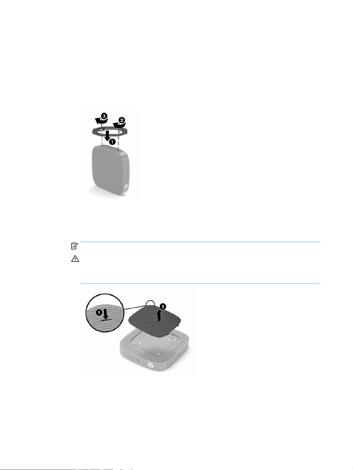
5. To attach the stand to the thin client:
● Attach the stand to the bottom of the thin client to use the thin client in the vertical orientation.
a. Turn the thin client upside down and locate the two screw holes in the grid on the bottom of the
thin client.
b. Position the stand over the bottom of the thin client (1) and install the two captive screws (2) to
secure the stand to the thin client.
● Attach the stand to the left side of the thin client to use it in the horizontal orientation.
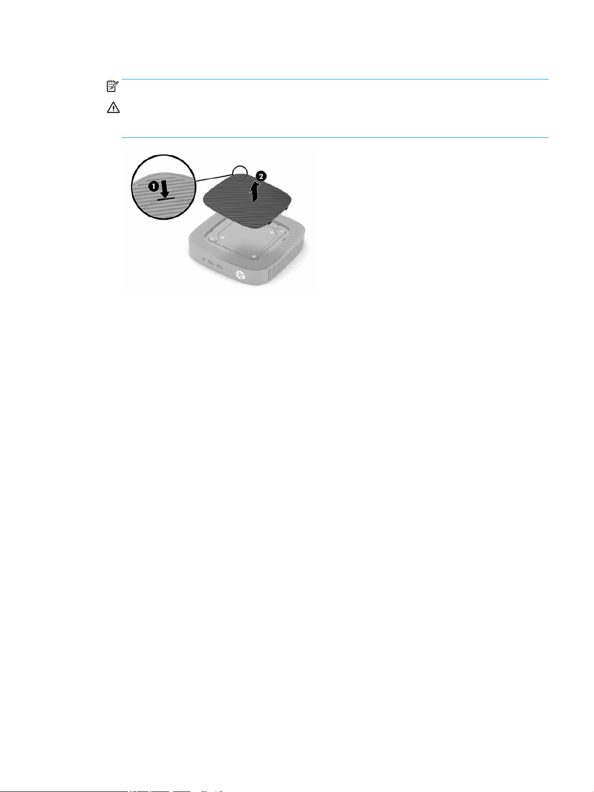
a. Lay the thin client down with the left side up and the front side with the HP logo facing you.
b. Insert a ngernail in the slot (1), and then lift the side cover (2) o the thin client.
NOTE: Retain the side cover for possible future use.
CAUTION: If the thin client has been in operation before removing the side cover, the metal plate
underneath the side cover can reach temperatures that may cause discomfort if directly touched.
Turn o the thin client and allow it to cool for 20 minutes to come to room temperature before
removing the side cover.
4 Chapter 1 Hardware Reference
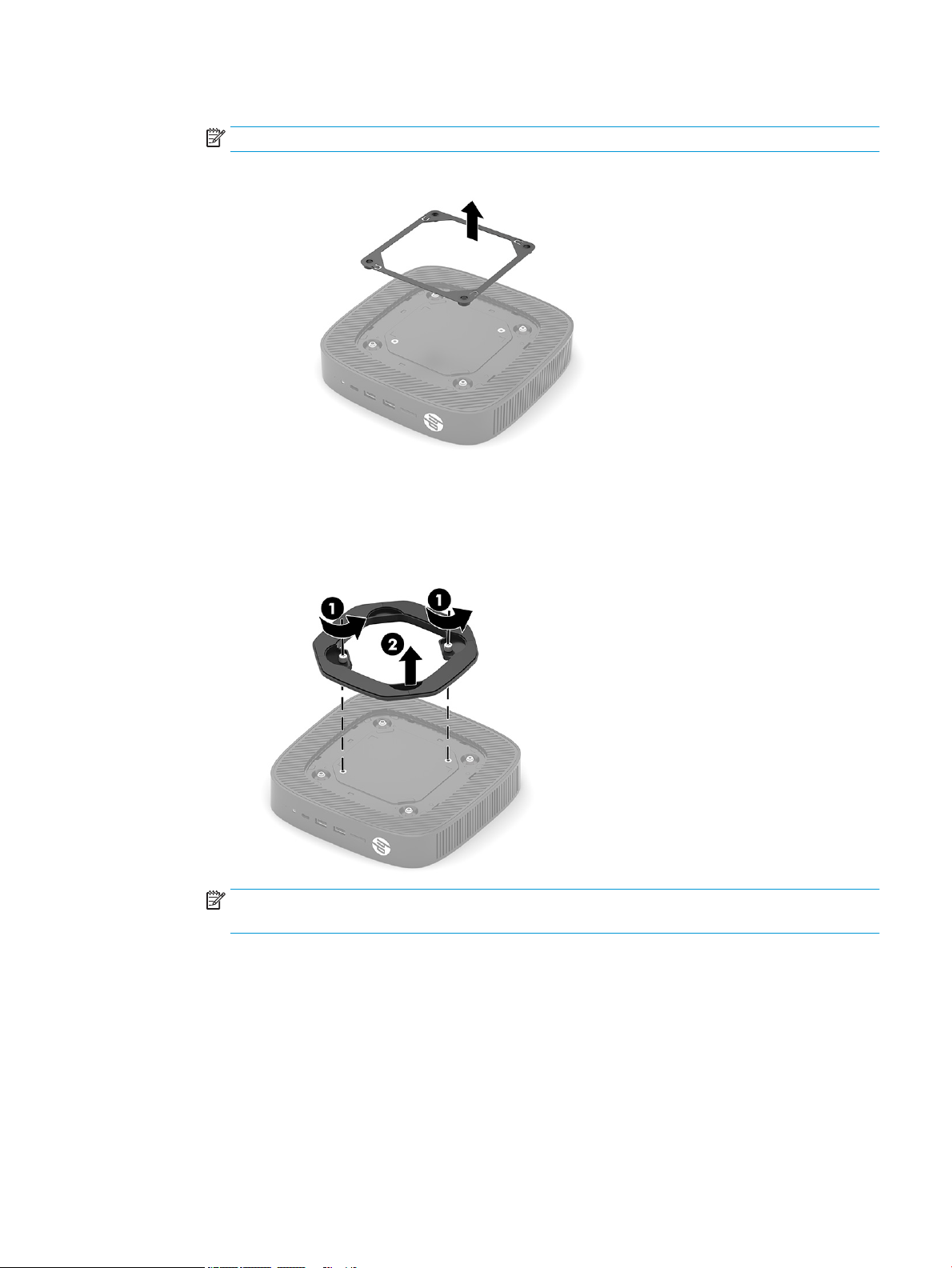
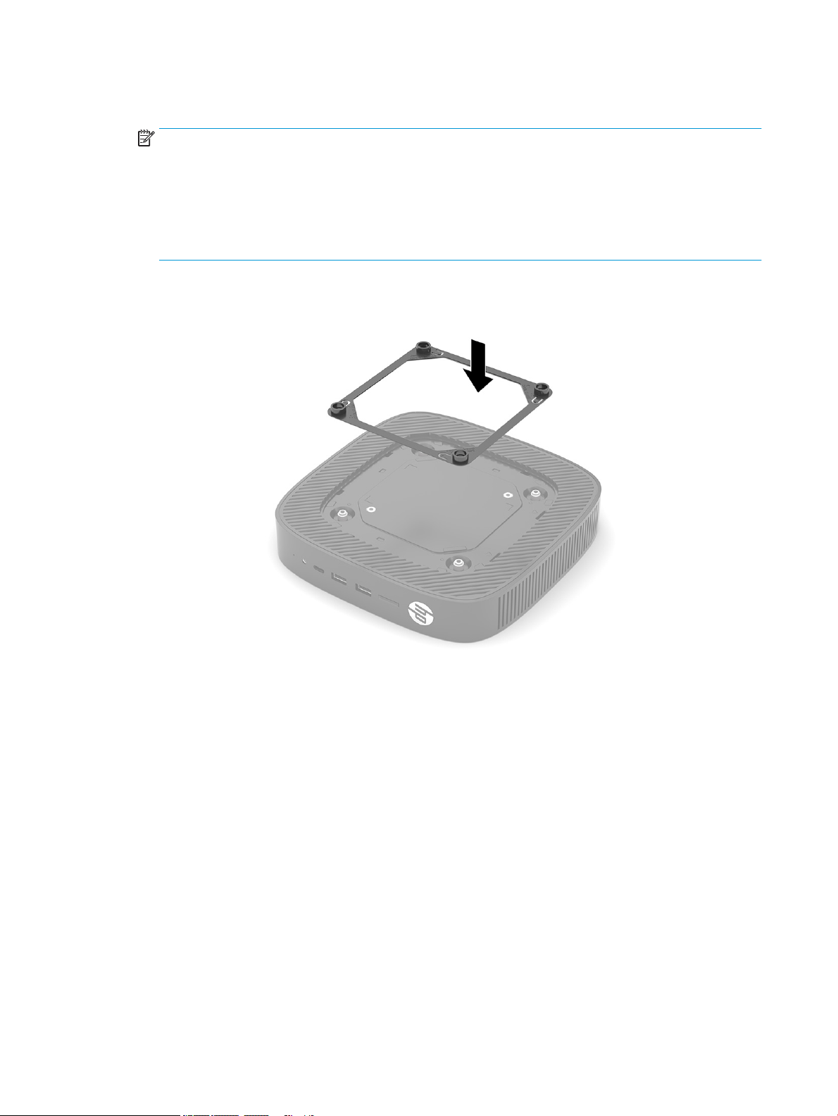
c. If your system includes a spacer bracket, remove the spacer bracket before installing the stand.
NOTE: Retain the spacer bracket for possible future use.
d. Locate the two screw holes on the left side of the thin client.
e. Position the stand over the side of the thin client (1) and install the captive screws (2) to secure the
stand to the thin client.
NOTE: Be sure that at least 2.54 cm (1 in) of space on all sides of the thin client remain clear and
free of obstructions.
Setup 5
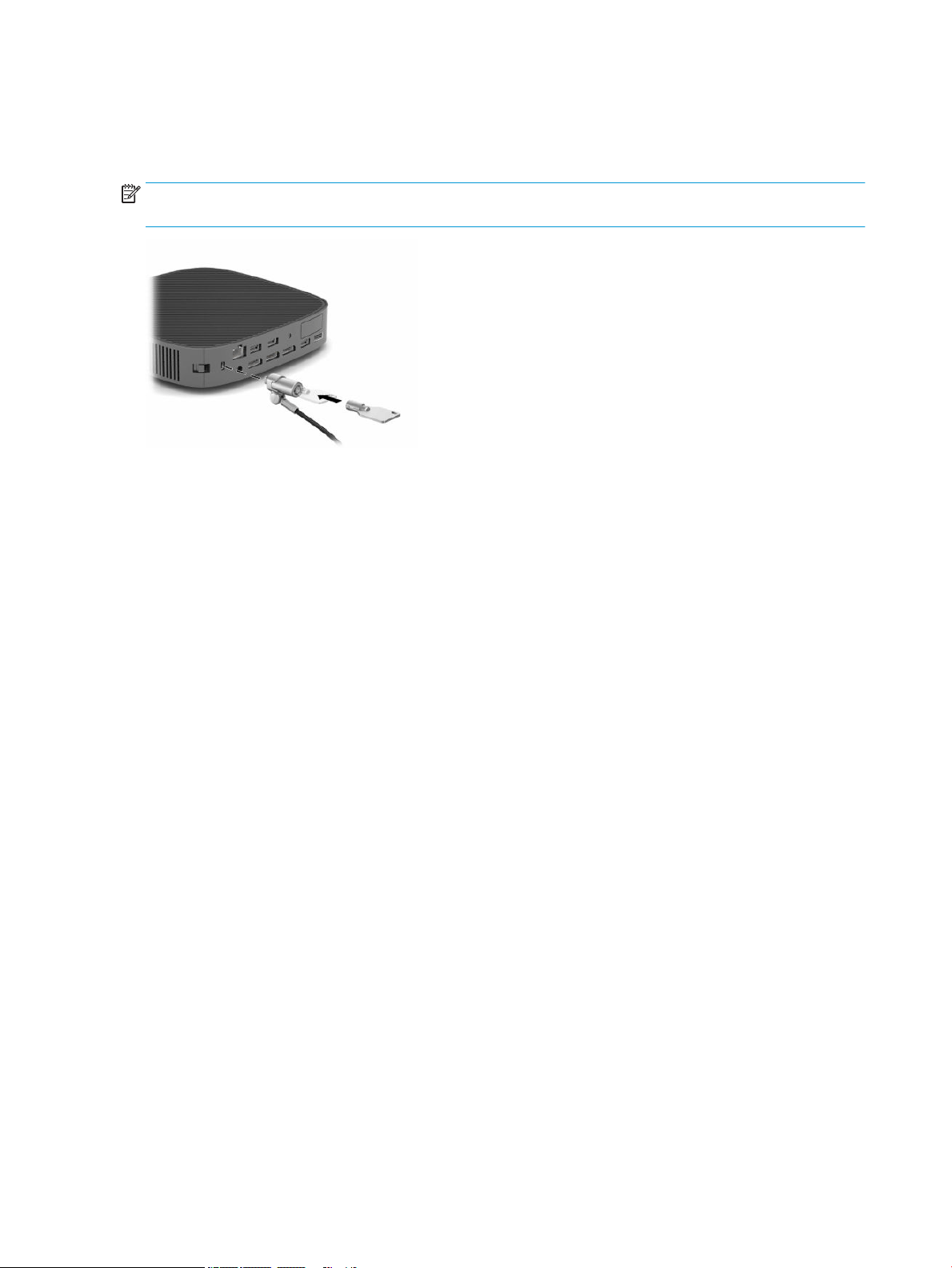
Installing a security cable
You can secure the thin client to a xed object with an optional security cable available from HP. Use the key
provided to attach and remove the lock.
NOTE: The security cable is designed to act as a deterrent, but it may not prevent the thin client from being
mishandled or stolen.
Mounting and orienting the thin client
This thin client incorporates four mounting points on the right side of the unit. These mounting points follow
the VESA (Video Electronics Standards Association) 100 mm standard, which provides industry-standard
mounting interfaces for various mounting brackets and accessories. HP oers various optional VESA-based
mounting brackets to mount the thin client to a multitude of at surfaces as well as swing arms and monitors
in a variety of environments and orientations.
To attach a mounting bracket to the thin client:
1. Remove any security devices that prohibit connecting the mounting bracket to the thin client.
2. Remove all removable media, such as USB ash drives, from the thin client.
3. If the thin client is turned on, turn o the thin client properly through the operating system, and then
turn o any external devices.
4. If the thin client is connected, disconnect the power cord from the AC outlet and disconnect any external
devices.
5. Lay the thin client down with the left side up and the front side with the HP logo facing you.
6 Chapter 1 Hardware Reference
6. Insert a ngernail in the slot (1), and then lift the side cover (2) o the thin client.
NOTE: Retain the side cover for possible future use.
CAUTION: If the thin client has been in operation, the metal plate underneath the side cover can reach
temperatures that may cause discomfort if you directly touch it. Turn o the thin client and allow it to
cool for 20 minutes to come to room temperature before removing the side cover.
Setup 7
7. If a spacer bracket is required for your mounting device, set the spacer bracket into the depression on
the side of the thin client.
NOTE: The VESA 100 mm mounting holes are recessed 2 mm below the surface of the chassis side
panel. Some models will include a 2 mm spacer bracket to assist with the installation of a mounting
device. If your model does not include the spacer bracket, you should still be able to install your VESA
100 mounting device to the thin client.
If the system includes a 2 mm spacer bracket and is congured in the horizontal orientation, the spacer
bracket may be stored on the inside of the VESA cover. Place the spacer bracket in the center of the VESA
cover and twist it slightly to lock it into the VESA cover for storage.
8. Attach the mounting device to the thin client according to the directions included with your mounting
device.
8 Chapter 1 Hardware Reference
Supported orientation and placement
CAUTION: If the thin client has been in operation, the metal plate underneath the side cover can reach
temperatures that may cause discomfort if directly touched. The thin client should be turned o and allowed
to cool for 20 minutes to come to room temperature before removing the wall mount kit.
IMPORTANT: You must adhere to the HP-supported orientation guidelines to ensure that your thin client
functions properly.
Unless the thin client is mounted with an approved VESA 100 mm mounting bracket, you must operate it with
the stand attached to ensure proper airow around the system.
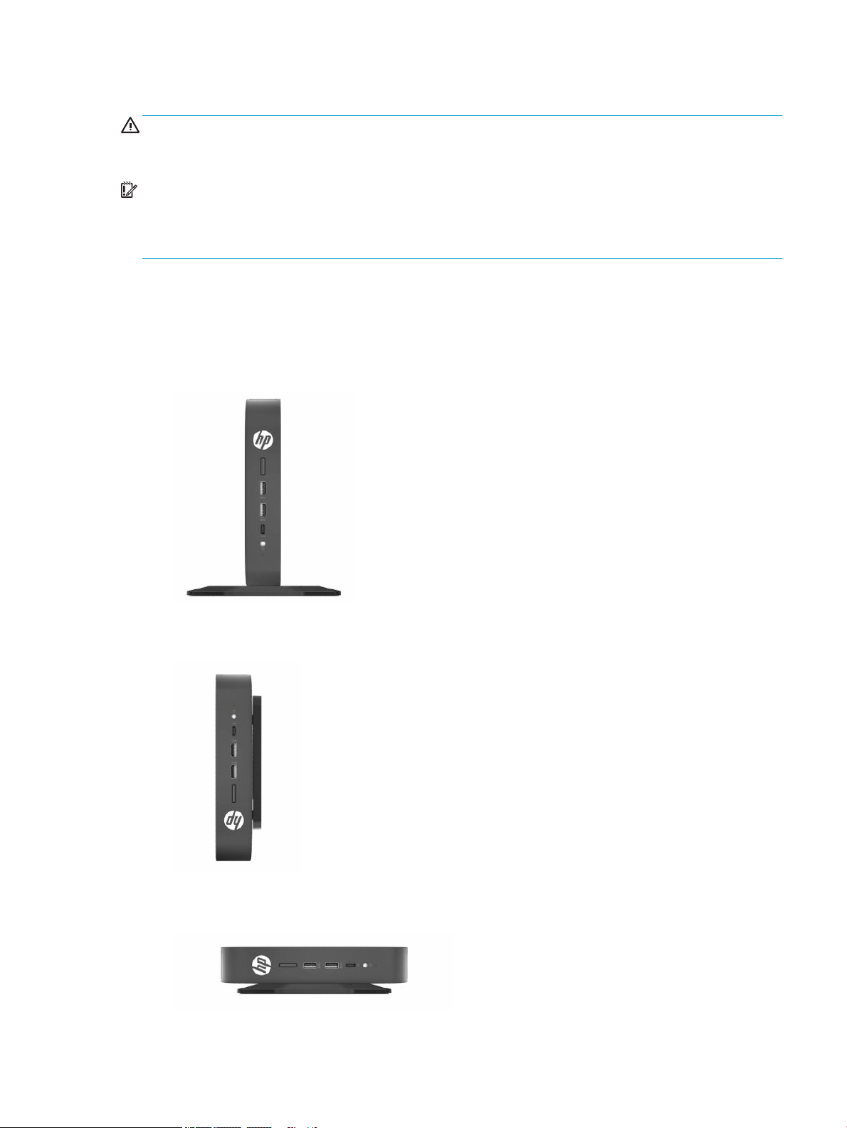
HP thin clients are uniquely designed to be set up and oriented in six dierent positions in order to support
any possible deployment scenario.
● Vertical Plus: This is the typical vertical deployment orientation on a desktop or other at surface with
the system stand attached to the bottom of the thin client and the HP logo oriented right side up. You
can also use Vertical Plus orientation to mount the thin client to a vertical at surface with a mounting
bracket.
● Vertical Minus: This orientation would typically be used to mount the thin client to a vertical at surface
with the HP logo positioned at the bottom in an upside down orientation.
● Horizontal Plus: This is the typical orientation for setting the thin client on a horizontal at surface,
such as a desktop, with the system stand attached to the side of the unit.
Setup 9
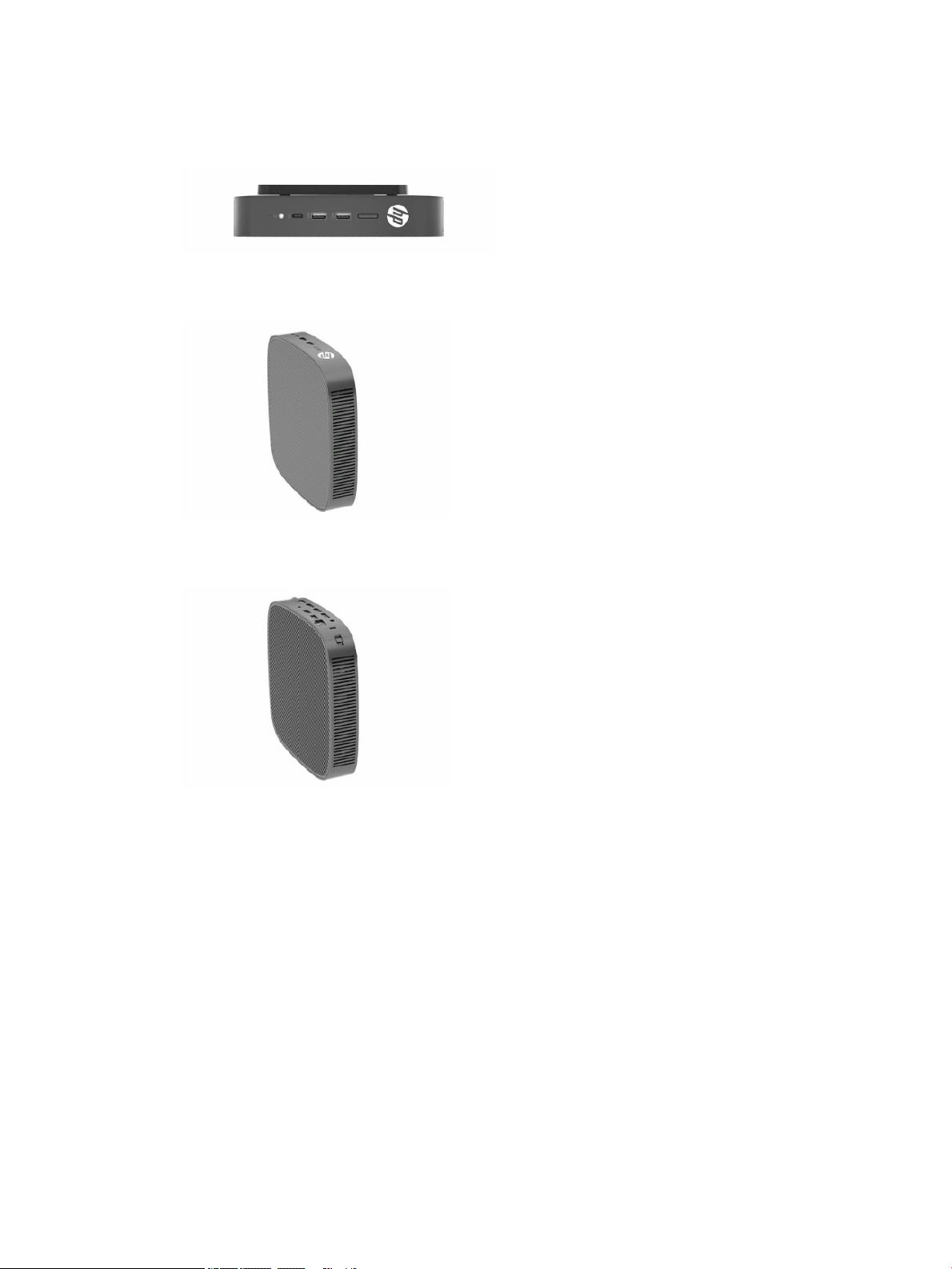
● Horizontal Minus: This is the typical orientation used when mounting the thin client underneath a
horizontal at surface using a mounting bracket to attach the unit to the under side of the at surface,
such as a desktop.
●
Bezel Plus: This orientation is used to mount the thin client on a vertical at surface, such as a wall, so
that the front Input/Output ports and system power button are facing up.
● Bezel Minus: In this orientation, the thin client is mounted to a vertical at surface so that the rear
Input/Output ports are facing up.
10 Chapter 1 Hardware Reference
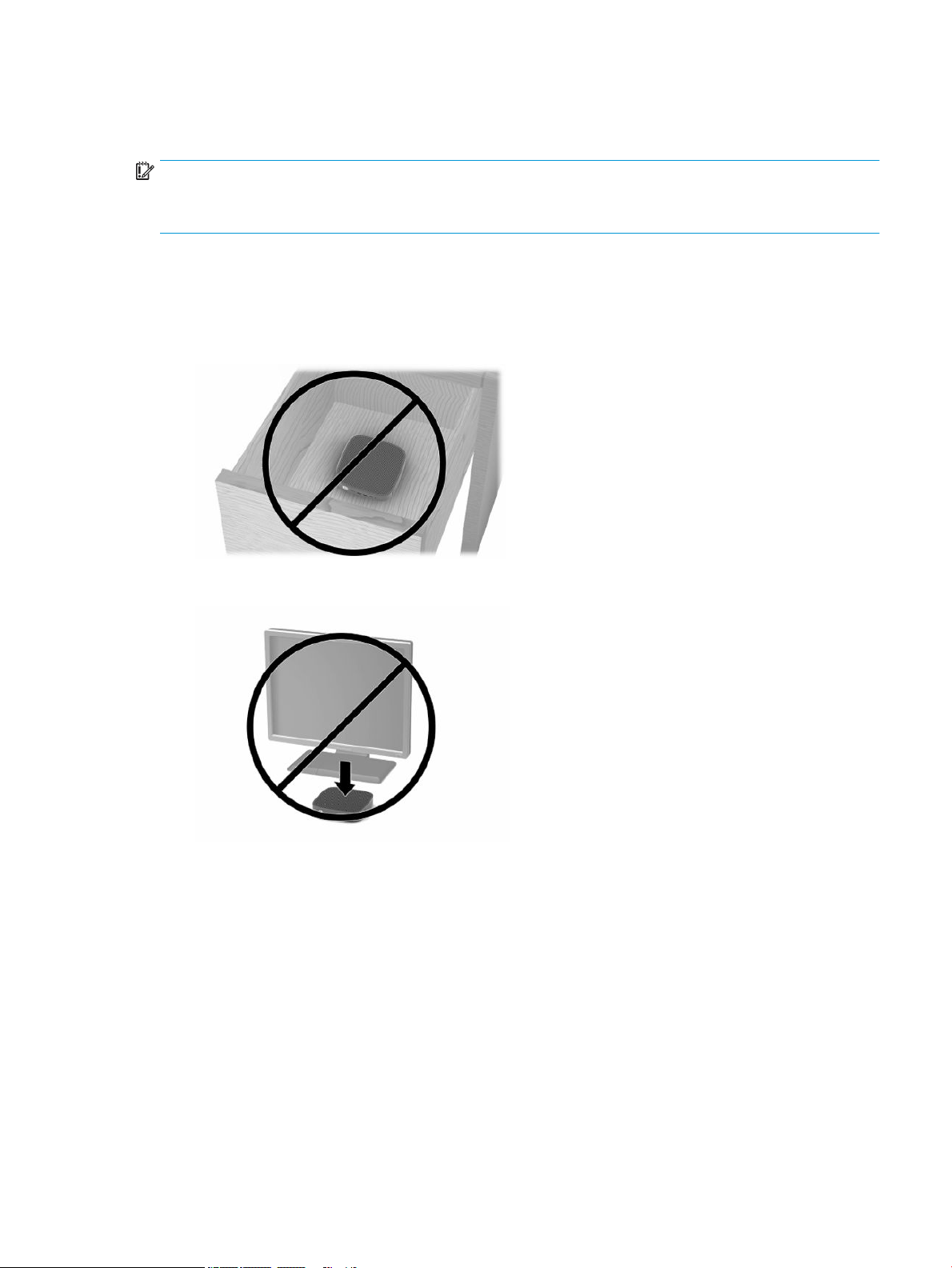
Unsupported placement
HP does not support the following placements for the thin client.
IMPORTANT: Unsupported placement of thin clients could result in operation failure, damage to the devices,
or both.
Thin clients require proper ventilation to maintain operating temperature. Do not block the vents.
Do not put thin clients in drawers or other sealed enclosures. Do not place a monitor or other object on top of
the thin client. Do not mount a thin client between the wall and a monitor unless you are using an approved
dual VESA mounting adapter specically designed for this mounting scenario. Thin clients require proper
ventilation to maintain operating temperatures.
● In a desk drawer:
● With a monitor on the thin client:
Setup 11
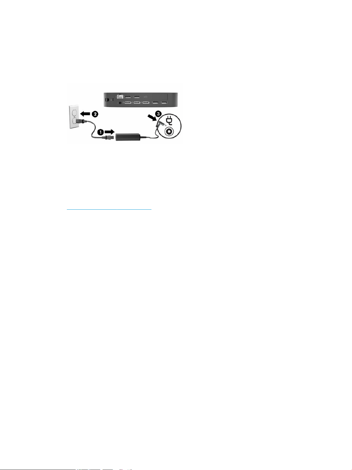
Connecting the AC adapter and power cord
1. Connect the power cord to the AC adapter (1).
2. Connect the power cord to an AC outlet (2).
3. Connect the AC adapter to the thin client (3).
Routine thin client care
Use the following information to properly care for your thin client:
● Never operate the thin client with the outside panel removed.
● Keep the thin client away from excessive moisture, direct sunlight, and extreme heat and cold. For
information about the recommended temperature and humidity ranges for the thin client, go to
http://www.hp.com/go/quickspecs.
● Keep liquids away from the thin client and keyboard.
● Turn o the thin client and wipe the exterior with a soft, damp cloth as needed. Using cleaning products
may discolor or damage the nish.
12 Chapter 1 Hardware Reference

2 Hardware Changes
Warnings and cautions
Before performing upgrades be sure to carefully read all of the applicable instructions, cautions, and
warnings in this guide.
WARNING! To reduce the risk of personal injury or equipment damage from electric shock, hot surfaces, or
re:
Energized and moving parts are inside. Disconnect power to the equipment before removing the enclosure.
Allow the internal system components to cool before you touch them.
Replace and secure the enclosure before re-energizing the equipment.
Do not plug telecommunications or telephone connectors into the network interface controller (NIC)
receptacles.
Do not disable the power cord grounding plug. The grounding plug is an important safety feature.
Plug the power cord into a grounded (earthed) AC outlet that is easily accessible at all times.
To reduce the risk of serious injury, read the Safety & Comfort Guide provided with your user guides. It
describes proper workstation setup and proper posture, health, and work habits for computer users. The
Safety & Comfort Guide also provides important electrical and mechanical safety information. The Safety &
Comfort Guide is also available on the Web at http://www.hp.com/ergo.
IMPORTANT: Static electricity can damage the electrical components of the thin client or optional
equipment. Before beginning the following procedures, be sure that you are discharged of static electricity by
briey touching a grounded metal object. See Preventing electrostatic damage on page 53 for more
information.
When the thin client is plugged into an AC power source, voltage is always applied to the system board. You
must disconnect the power cord from the power source before opening the thin client to prevent damage to
internal components.
Removing and replacing the access panel
Table
2-1 Burn hazard warning
Burn hazard warning
CAUTION: Burn hazard! To avoid potential burns, wait 20 minutes after turning o the thin client before
removing and replacing the access panel.
Warnings and cautions 13
Removing the access panel
WARNING! To reduce the risk of personal injury or equipment damage from electric shock, hot surfaces, or
re, always operate the thin client with the access panel in place. In addition to enhancing safety, the access
panel may provide important instructions and identication information, which may be lost if the access
panel is not used. Do not use any access panel except the one that is provided by HP for use with this thin
client.
Before removing the access panel, be sure that the thin client is turned o and the power cord is disconnected
from the AC outlet.
To remove the access panel:
1. Remove any security devices that prohibit opening the thin client.
2. Remove all removable media, such as USB ash drives, from the thin client.
3. Turn o the thin client properly through the operating system, and then turn o any external devices.
4. Disconnect the power cord from the AC outlet, and disconnect any external devices.
IMPORTANT: Regardless of the power-on state, voltage is always present on the system board as long
as the system is plugged into an active AC outlet. You must disconnect the AC power cord to avoid
damage to the internal components of the thin client.
5. Remove the stand or mounting bracket from the thin client if necessary.
6. Lay the thin client at on a stable surface with the right side up.
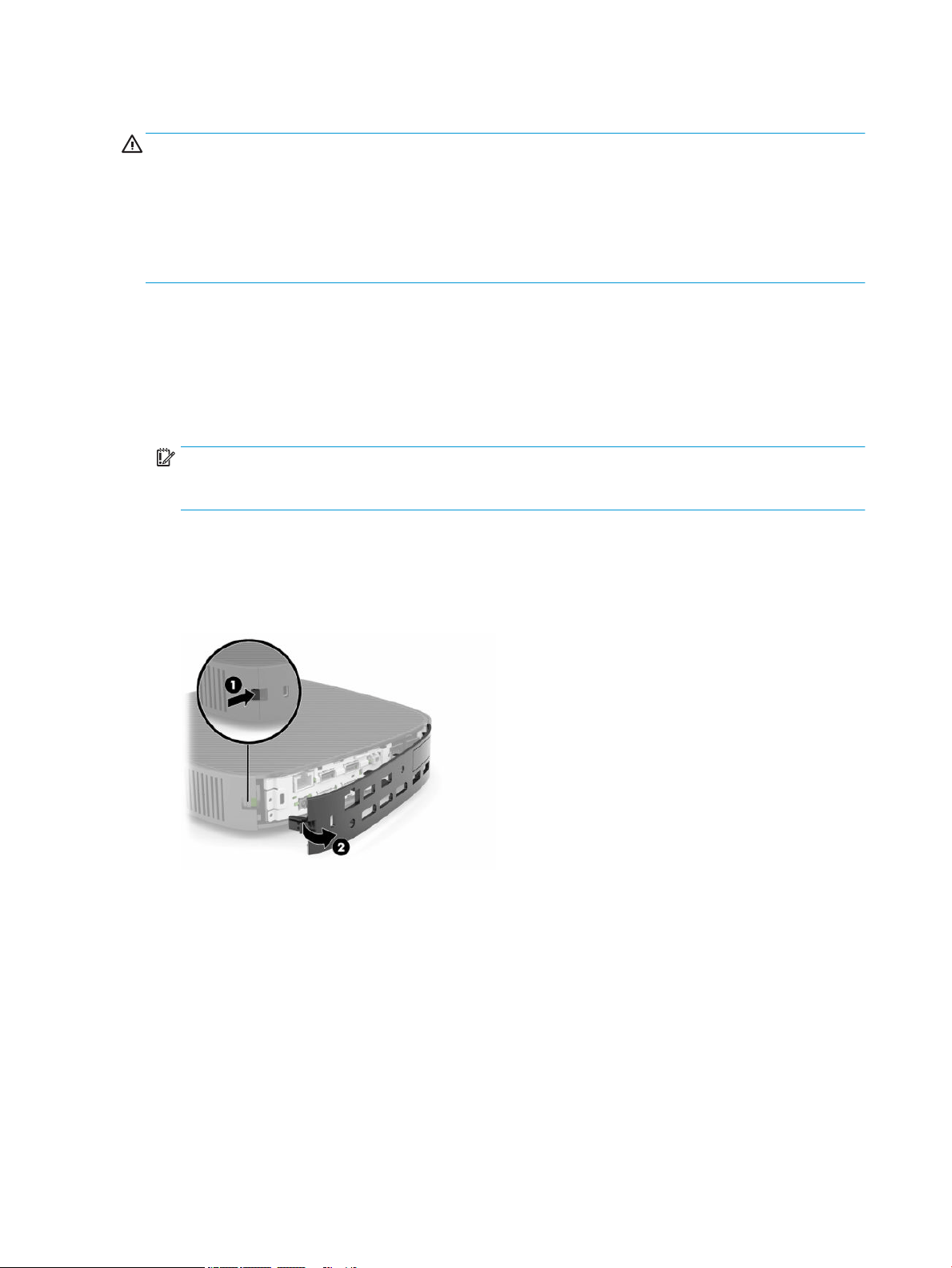
7. Release the latch (1) on the left side of the rear I/O panel, rotate the I/O panel (2) to the right, and then
pull it o the thin client.
8. Press the access panel latch (1) to release the access panel.
14 Chapter 2 Hardware Changes
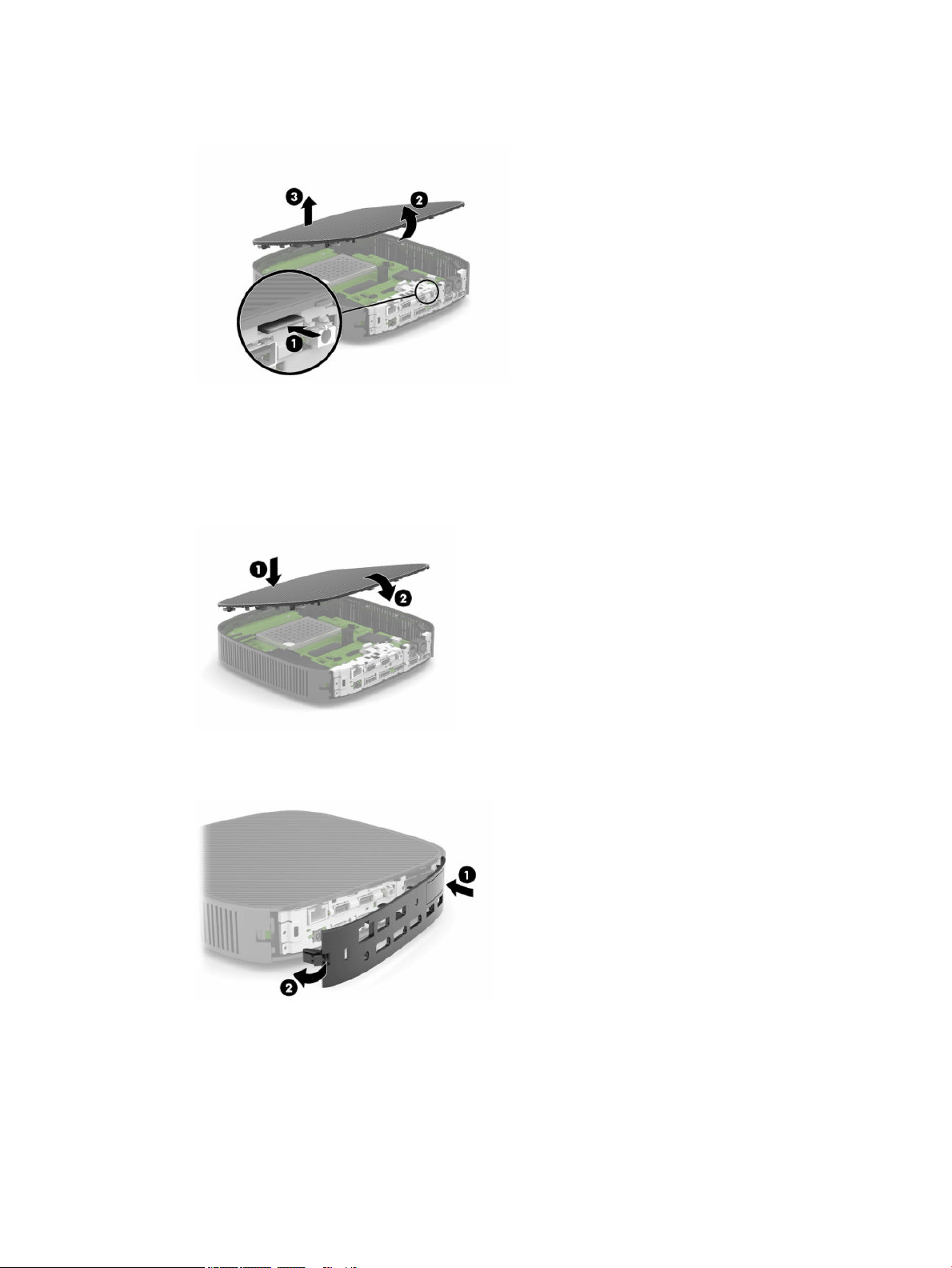
9. Rotate the rear of the access panel (2) up, and then lift the front of the access panel (3) up and o the
chassis.
Replacing the access panel
To replace the access panel:
1. Angle the access panel with the hinged side into the front of the system (1), and then rotate the rear of
the access panel down (2) so that it snaps in place.
2. Insert the hooks on the right side of the rear I/O panel (1) into the right side of the back of the chassis,
rotate the left side (2) to the chassis, and then press it to the chassis until it locks in place.
3. Replace the thin client stand or mounting bracket if removed.
4. Reconnect the power cord and turn on the thin client.
5. Lock any security devices that were disengaged when the thin client access panel was removed.
Removing and replacing the access panel 15
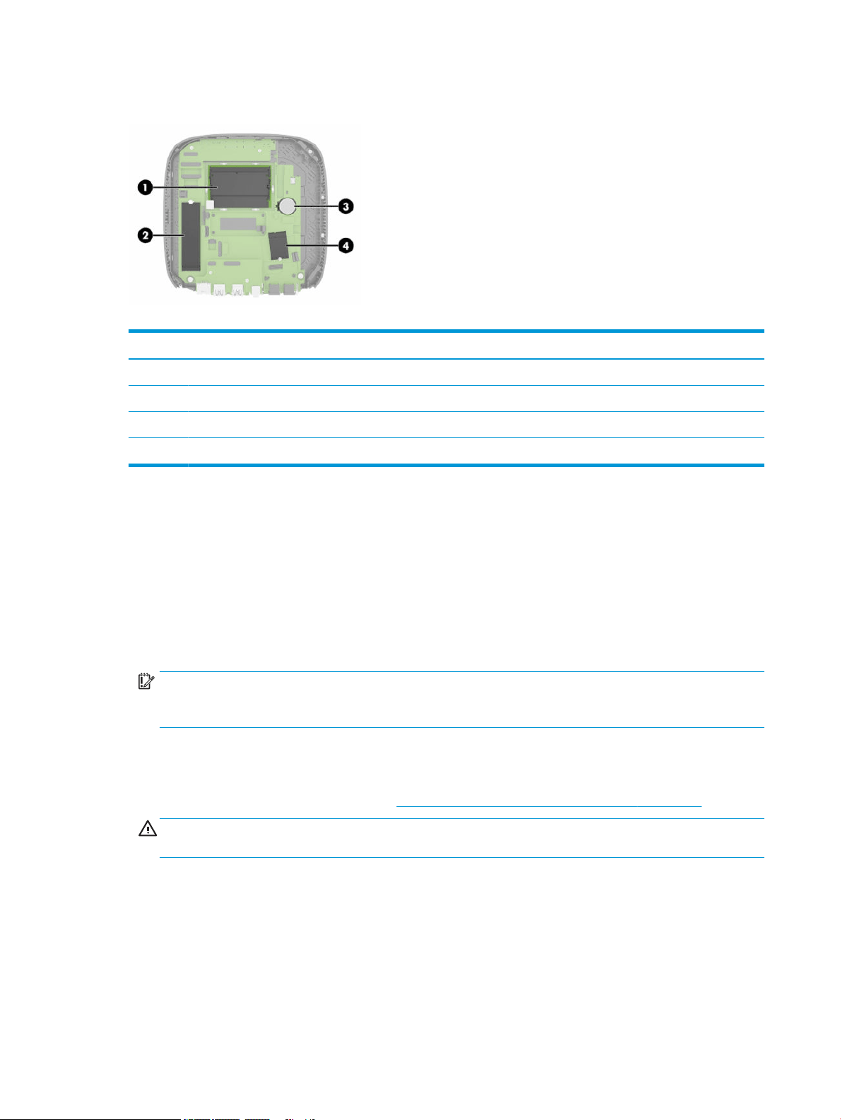
Locating internal components
Table 2-2 Internal components
Components
(1) DDR4 SDRAM Memory (2 SODIMMs)
(2) M.2 ash storage module
(3) Battery
(4) WLAN card (select models only)
Removing and replacing the M.2 ash storage module
To remove the M.2 ash storage module:
1. Remove any security devices that prohibit opening the thin client.
2. Remove all removable media, such as USB ash drives, from the thin client.
3. Turn o the thin client properly through the operating system, and then turn o any external devices.
4. Disconnect the power cord from the AC outlet, and disconnect any external devices.
IMPORTANT: Regardless of the power-on state, voltage is always present on the system board as long
as the system is plugged into an active AC outlet. You must disconnect the AC power cord to avoid
damage to the internal components of the thin client.
5. Remove the stand or mounting bracket from the thin client.
6. Lay the unit at on a stable surface.
7. Remove the thin client access panel. See Removing and replacing the access panel on page 13.
CAUTION: To reduce risk of personal injury from hot surfaces, allow the internal system components
to cool before you touch them.
8. Locate the M.2 socket for the ash storage module on the system board.
9. Loosen the screw securing the ash storage module until the end of the module can be raised.
16 Chapter 2 Hardware Changes
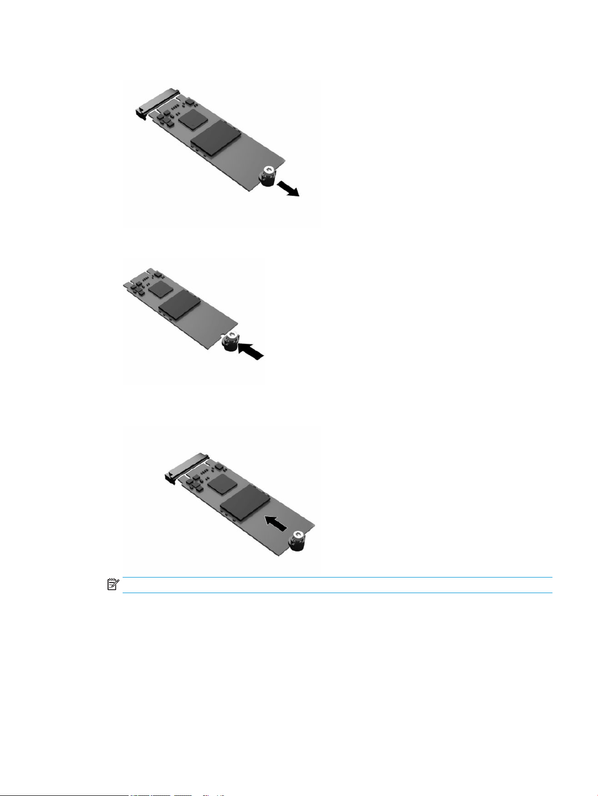
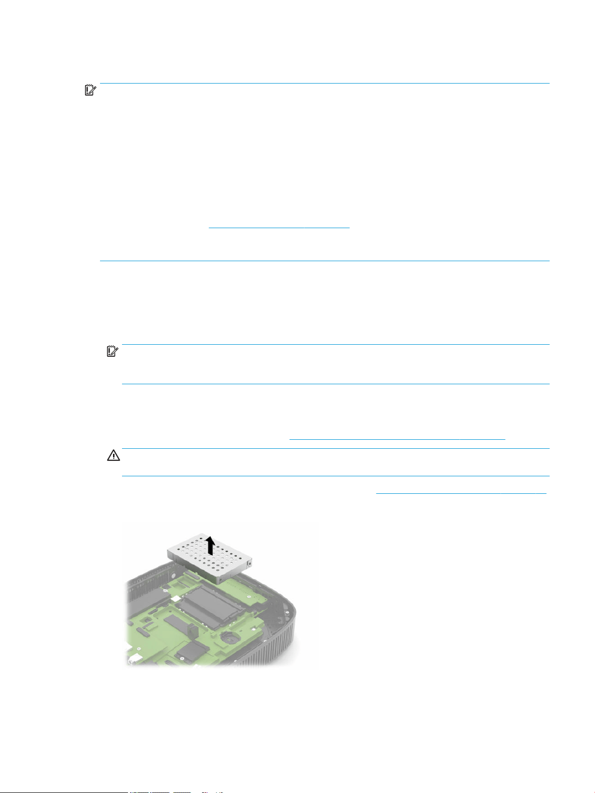
10. Pull the ash storage module out of the socket.
11. Pull the screw kit o of the ash storage module and attach it to the replacement ash storage module.
12. Slide the new ash storage module into the M.2 socket on the system board and press the module
connectors rmly into the socket.
NOTE: A ash storage module can be installed in only one way.
Removing and replacing the M.2 ash storage module 17
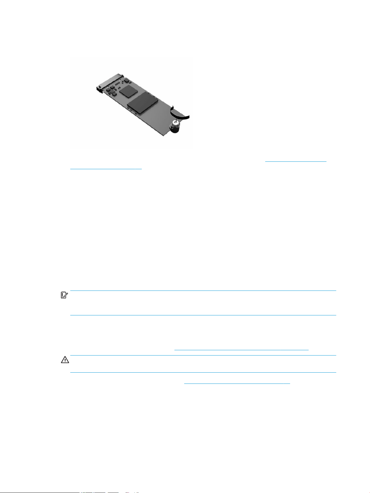
13. Press the ash storage module down, and use a screwdriver to tighten the screw and secure the module
to the system board.
14. Replace and latch the access panel, and then reinstall the rear I/O panel. See Removing and replacing
the access panel on page 13.
15. Replace the thin client stand or mounting bracket.
16. Reconnect the power cord and turn on the thin client.
17. Lock any security devices that were disengaged when the thin client access panel was removed.
Removing and replacing the battery
To remove and replace the battery:
1. Remove any security devices that prohibit opening the thin client.
2. Remove all removable media, such as USB ash drives, from the thin client.
3. Turn o the thin client properly through the operating system, and then turn o any external devices.
4. Disconnect the power cord from the AC outlet, and disconnect any external devices.
IMPORTANT: Regardless of the power state, voltage is always present on the system board as long as
the system is plugged into an active AC outlet. You must disconnect the AC power cord to avoid damage
to the internal components of the thin client.
5. Remove the stand or mounting bracket from the thin client.
6. Lay the unit at on a stable surface.
7. Remove the thin client access panel. See Removing and replacing the access panel on page 13.
CAUTION: To reduce risk of personal injury from hot surfaces, allow the internal system components
to cool before you touch them.
8. Locate the battery on the system board. See Locating internal components on page 16.
18 Chapter 2 Hardware Changes
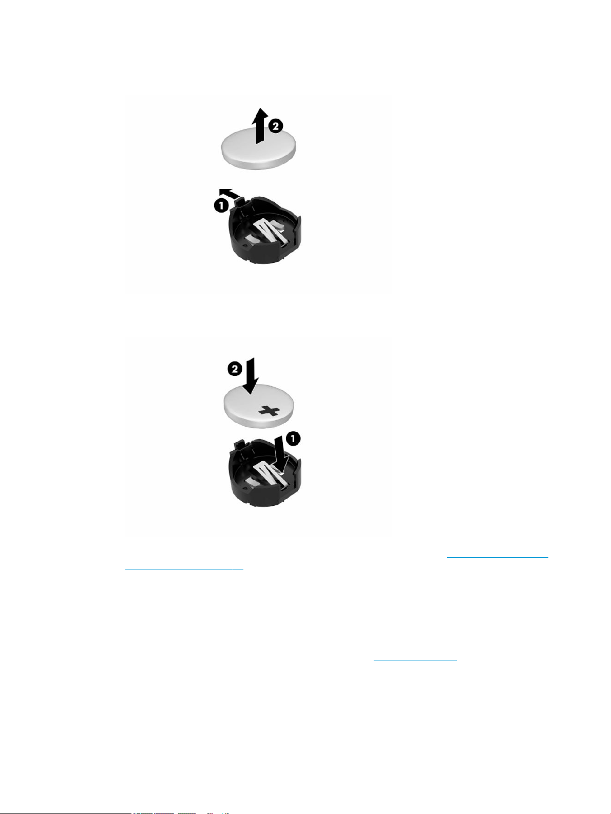
9. To release the battery from its holder, squeeze the metal clamp (1) that extends above one edge of the
battery. When the battery pops up, lift it out (2).
10. To insert the new battery, slide one edge of the replacement battery under the holder’s lip (1) with the
positive side up. Push the other edge down until the clamp snaps over the other edge of the battery (2).
11. Replace and latch the access panel, and then reinstall the rear I/O panel. See Removing and replacing
the access panel on page 13.
12. Replace the thin client stand or mounting bracket.
13. Reconnect the power cord and turn on the thin client.
14. Lock any security devices that were disengaged when you removed the thin client access panel.
HP encourages customers to recycle used electronic hardware, HP original print cartridges, and rechargeable
batteries. For more information about recycling programs, go to http://www.hp.com and search for “recycle.”
Removing and replacing the battery 19

Table 2-3 Battery icon denitions
Icon Denition
Do not dispose of batteries, battery packs, and accumulators with the general household waste.
For recycling or proper disposal, use the public collection system or return them to HP, an
authorized HP partner, or their agents.
The Taiwan EPA requires dry battery manufacturing or importing rms, in accordance with Article
15 or the Waste Disposal Act, to indicate the recovery marks on the batteries used in sales,
giveaways, or promotions. Contact a qualied Taiwanese recycler for proper battery disposal.
Upgrading system memory
The memory sockets on the system board can be populated with up to two industry-standard SODIMMs.
These memory sockets are populated with at least one preinstalled SODIMM. To achieve the maximum system
performance, HP recommends the unit be congured for dual-channel memory by populating both SODIMM
slots with a SODIMM memory module.
For proper system operation, the memory modules must adhere to the following specications:
● Industry-standard 260-pin Small Outline DIMM (SODIMM)
● Unbuered non-ECC DDR4 SDRAM
● Contain the mandatory Joint Electronic Device Engineering Council (JEDEC) specication
The thin client supports the following:
● 4 GB, 8 GB, and 16 GB non-ECC memory modules
● Single-sided and double-sided SODIMMS
NOTE: The system does not operate properly when an unsupported memory module is installed.
Table 2-4 Recommended memory support for monitors
Windows® 10 IoT RS5 FHD
1920 × 1080 @ 60 Hz
UHD / 4K
3840 × 2160 @ 60 Hz
Memory conguration single/dual channel dual channel
Maximum number of supported monitors 3 3
1080p video playback yes yes
4K video playback yes yes
NOTE: HP recommends dual-channel memory for 4K monitors for optimized performance.
20 Chapter 2 Hardware Changes
Removing and installing a memory module
IMPORTANT: You must unplug the power cord and wait approximately 30 seconds for the power to drain
before adding or removing the memory module. Regardless of the power state, voltage is always supplied to
the memory module as long as the thin client is plugged into an active AC outlet. Adding or removing the
memory module while voltage is present may cause irreparable damage to the memory module or system
board.
The memory module socket has gold-plated metal contacts. When upgrading the memory, use a memory
module with gold-plated metal contacts to prevent corrosion, oxidation, or both resulting from having
incompatible metals in contact with each other.
Static electricity can damage the electronic components of the thin client. Before beginning the following
procedures, be sure that you are discharged of static electricity by
briey touching a grounded metal object.
For more information, see Electrostatic discharge on page 53.
When handling a memory module, be careful not to touch any of the contacts. Doing so may damage the
module.
1. Remove any security devices that prohibit opening the thin client.
2. Remove all removable media, such as USB ash drives, from the thin client.
3. Turn o the thin client properly through the operating system, and then turn o any external devices.
4. Disconnect the power cord from the AC outlet, and disconnect any external devices.
IMPORTANT: Regardless of the power state, voltage is always present on the system board as long as
the system is plugged into an active AC outlet. You must disconnect the AC power cord to avoid damage
to the internal components of the thin client.
5. Remove the stand or mounting bracket from the thin client.
6. Lay the unit at on a stable surface.
7. Remove the thin client access panel. See Removing and replacing the access panel on page 13.
CAUTION: To reduce risk of personal injury from hot surfaces, allow the internal system components
to cool before you touch them.
8. Locate the memory module sockets on the system board. See Locating internal components on page 16.
9. Remove the memory module shield.
Upgrading system memory 21
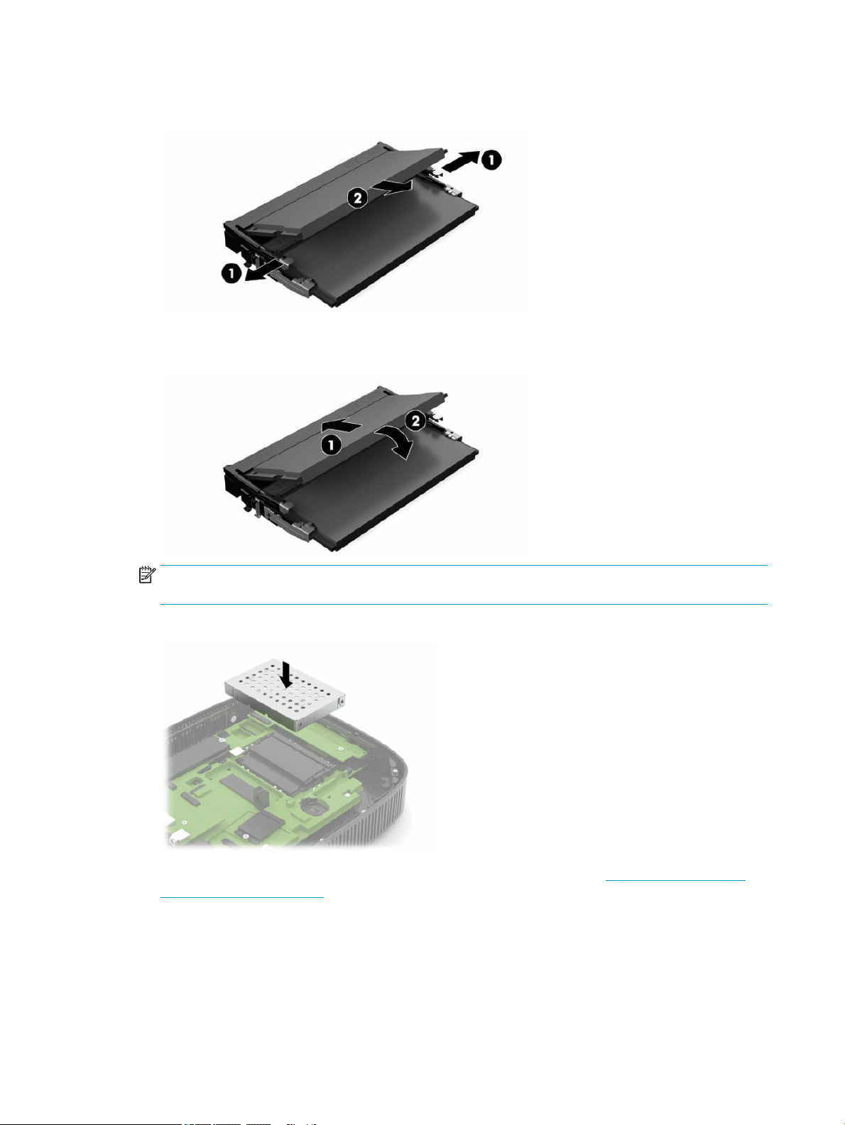
10. To remove the memory module, press outward on the latches on each side of the memory module (1),
rotate the memory module up, and then pull the memory module out of the socket (2).
11. Slide the new memory module (1) into the socket at approximately a 30° angle, and then press the
memory module down (2) so that the latches lock it in place.
NOTE: A memory module can be installed in only one way. Match the notch on the module with the tab
on the memory socket.
12. Replace the memory module shield.
13. Replace and latch the access panel, and then reinstall the rear I/O panel. See Removing and replacing
the access panel on page 13.
14. Replace the thin client stand or mounting bracket.
15. Reconnect the power cord and turn on the thin client.
16. Lock any security devices that were disengaged when you removed the thin client access panel.
The thin client automatically recognizes the new memory when you turn on the thin client.
22 Chapter 2 Hardware Changes
Replacing a WLAN card
1. Remove any security devices that prohibit opening the thin client.
2. Remove all removable media, such as USB ash drives, from the thin client.
3. Turn o the thin client properly through the operating system, and then turn o any external devices.
4. Disconnect the power cord from the AC outlet, and disconnect any external devices.
IMPORTANT: Regardless of the power-on state, voltage is always present on the system board as long
as the system is plugged into an active AC outlet. You must disconnect the AC power cord to avoid
damage to the internal components of the thin client.
5. Remove the stand or mounting bracket from the thin client.
6. Lay the unit at on a stable surface.
7. Remove the thin client access panel. See Removing and replacing the access panel on page 13.
CAUTION: To reduce risk of personal injury from hot surfaces, allow the internal system components
to cool before you touch them.
8. Locate the WLAN card on the system board. See Locating internal components on page 16.
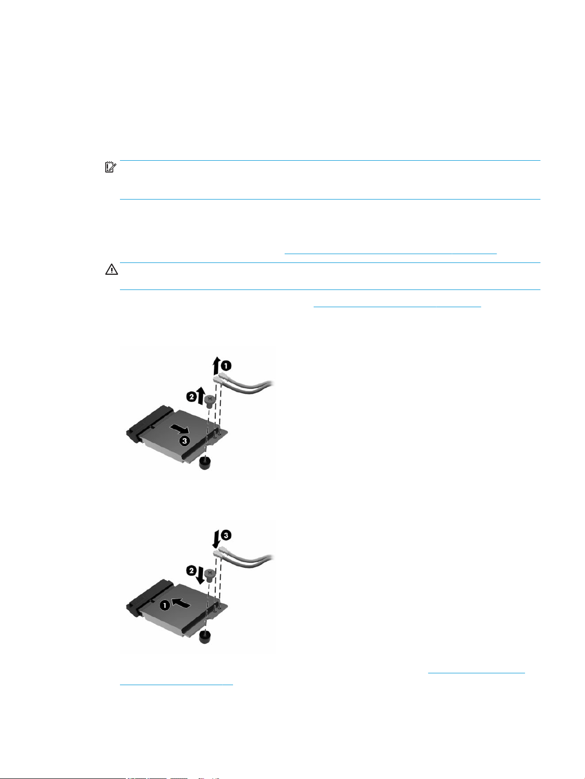
9. Disconnect the cables (1) from the WLAN card, remove the screw (2) that secures the WLAN card, and
then pull the WLAN card out of its socket (3).
10. Insert the WLAN card into its socket (1), install the screw to secure the WLAN card (2), and then connect
the cables to the WLAN card (3).
11. Replace and latch the access panel, and then reinstall the rear I/O panel. See Removing and replacing
the access panel on page 13.
12. Replace the thin client stand or mounting bracket.
Replacing a WLAN card 23

13. Reconnect the power cord and turn on the thin client.
14. Lock any security devices that were disengaged when the thin client access panel was removed.
24 Chapter 2 Hardware Changes

3 Troubleshooting
Computer Setup (F10) Utility, BIOS Settings
Computer Setup (F10) Utility
Use Computer Setup (F10) Utility to do the following tasks:
● Change factory default settings.
● Set the system date and time.
● Set, view, change, or verify the system conguration, including settings for processor, graphics,
memory, audio, storage, communications, and input devices.
● Modify the boot order of bootable devices such as solid-state drives or USB ash drives.
● Select POST Messages Enabled or Disabled to change the display status of Power-On Self-Test (POST)
messages. POST Messages Disabled suppresses most POST messages, such as memory count, product
name, and other nonerror text messages. If a POST error occurs, the error is displayed regardless of the
mode selected. To manually switch to POST Messages Enabled during POST, press any key (except F1
through F12).
● Enter the Asset Tag or property identication number assigned by the company to this computer.
● Enable the power-on password prompt during system restarts (warm boots) as well as during power-on.
● Establish a setup password that controls access to the Computer Setup (F10) Utility and the settings
described in this section.
● Secure integrated I/O functionality, including the USB, audio, or embedded NIC, so that they cannot be
used until they are unsecured.
Computer Setup (F10) Utility, BIOS Settings 25

Using Computer Setup (F10) Utility
You can access Computer Setup only by turning the computer on or restarting the system. To access the
Computer Setup Utility menu, complete the following steps:
1. Turn on or restart the computer.
2. Press either esc or F10 while the “Press the ESC key for Startup Menu” message is displayed at the
bottom of the screen.
Pressing esc displays a menu that allows you to access dierent options available at startup.
NOTE: If you do not press esc or F10 at the appropriate time, you must restart the computer and again
press esc or F10 when the monitor light turns green to access the utility.
NOTE: You can select the language for most menus, settings, and messages using the Language
Selection option using the F8 key in Computer Setup.
3. If you pressed esc, press F10 to enter Computer Setup.
A choice of ve headings appears in the Computer Setup Utility menu: File, Storage, Security, Power, and
Advanced.
4. Use the arrow (left and right) keys to select the appropriate heading. Use the arrow (up and down) keys
to select the option you want, and then press enter. To return to the Computer Setup Utility menu, press
esc.
5. To apply and save changes, select File > Save Changes and Exit.
● If you have made changes that you do not want applied, select Ignore Changes and Exit.
● To reset to factory settings, select Apply Defaults and Exit. This option restores the original
factory system defaults.
IMPORTANT: To reduce the risk of corrupting the CMOS, do not turn the computer power o while the BIOS
is saving the Computer Setup (F10) changes. It is safe to turn o the computer only after exiting the F10
Setup screen.
Table 3-1 Computer Setup Utility menu options
Heading Table
File Computer Setup—File on page 27
Storage Computer Setup—Storage on page 28
Security Computer Setup—Security on page 29
Power Computer Setup—Power on page 30
Advanced Computer Setup—Advanced on page 31
26 Chapter 3 Troubleshooting

Computer Setup—File
NOTE: Support for specic Computer Setup options can vary, depending on the hardware conguration.
Table 3-2 Computer Setup—File
Option Description
System Information Lists:
● Product Name
● Memory Size
● PROCESSOR 1
● Processor Type
● Processor Speed
● Processor stepping
● Cache Size (L1/L2/L3)
● Processor Stepping
● Memory Speed Channel A and Channel B
● FIRMWARE
● System BIOS
● USB Type C PD FW
● Wake from Keyboard in S5 FW Version
● TPM FW Version
● SERVICE
● Chassis Serial Number
● SKU Number
● UUID
● Asset Tracking Number
● Asset Tracking Number
● Feature Byte
● Build ID
● Product Family
● System Board CT Number
● COMMUNICATION
● Integrated MAC
About Displays copyright notice.
BIOS Cong. Utility Allows you to do the following tasks:
● Save Current Setting to File in ESP
● Restore Former Setting from File in ESP
Flash System BIOS Allows you to ash system BIOS from a USB recovery key.
Allows you to do the following tasks:
Computer Setup (F10) Utility, BIOS Settings 27

Table 3-2 Computer Setup—File (continued)
Option Description
● Update System BIOS from USB
● Update USB Type C PD FW
● Update TPM FW
● Update Wake from Keyboard in S5 HOST FW
Set Time and Date Allows you to set system time and date.
Default Setup Allows you to do the following tasks:
● Save Current Settings as Default
● Restore Factory Settings as Default
Apply Defaults and Exit Loads the original factory system conguration settings for use by a subsequent Apply Defaults and Exit
action.
Ignore Changes and Exit Exits Computer Setup without applying or saving any changes.
Save Changes and Exit Saves changes to system conguration or default settings and exits Computer Setup.
Computer Setup—Storage
Table
3-3 Computer Setup—Storage
Option Description
Device Conguration Lists all installed BIOS-controlled storage devices. When a device is selected, detailed information and
options are displayed. The following options may be presented:
Hard Disk: Size, model.
Storage Options External USB Storage Boot
Allows you to set USB storage device default boot option in CSM or Legacy mode.
Boot Order Allows you to do the following tasks:
● Specify the order in which EFI boot sources (such as an internal drive, USB hard drive, or USB optical
drive) are checked for a bootable operating system image. Each device on the list may be individually
excluded from or included for consideration as a bootable operating system source. EFI boot sources
always have precedence over legacy boot sources.
● Specify the order in which legacy boot sources (such as a network interface card, internal drive, or
USB optical drive) are checked for a bootable operating system image. Each device on the list may be
individually excluded from or included for consideration as a bootable operating system source.
● Specify the order of attached hard drives. The rst hard drive in the order will have priority in the
boot sequence and will be recognized as drive C (if any devices are attached).
NOTE: You can use F5 to disable individual boot items, as well as disable EFI boot, legacy boot, or both.
MS-DOS drive lettering assignments may not apply after a non-MS-DOS operating system has started.
Shortcut to Temporarily Override Boot Order
To boot one time from a device other than the default device specied in Boot Order, restart the computer
and press esc (to access the boot menu) and then F9 (Boot Order), or only F9 (skipping the boot menu)
when the monitor light turns green. After POST is completed, a list of bootable devices is displayed. Use
the arrow keys to select the preferred bootable device and press enter. The computer then boots from the
selected device for this one time.
28 Chapter 3 Troubleshooting

Computer Setup—Security
NOTE: Support for specic Computer Setup options can vary, depending on the hardware conguration.
Table 3-4 Computer Setup—Security
Option Description
Setup Password Allows you to set and enable a setup (administrator) password.
NOTE: If the setup password is set, you must change Computer Setup options, ash the ROM, and make
changes to certain Plug and Play settings under Windows.
Power-On Password Allows you to set and enable a power-on password. The power-on password prompt appears after a
power cycle or reboot. If the user does not enter the correct power-on password, the thin client will not
boot.
Password Options
(This selection appears
only if a power-on
password or setup
password is set.)
Allows you to enable/disable:
● Stringent Password—When set, enables a mode in which there is no physical bypass of the
password function. If enabled, removing the password jumper will be ignored.
● Password Prompt on F9 & F12—Default is enabled.
● Setup Browse Mode—Allows viewing, but not changing, the F10 Setup Options without entering
setup password. Default is enabled.
Device Security Allows you to set Device Available or Device Hidden (default is Device Available) for the following:
● System Audio
● Network Controller
● M.2 Storage
● Onboard LAN DASH (Default Disabled)
● Data Execution Prevention (Default Enabled)
● Virtualization Technology VTx
● TPM Device
● TPM State
● Clear TPM
USB Security Allows you to set Enabled or Disabled (default is Enabled) for:
● Front USB Ports
– USB Port 1
– USB Port 2
– USB Port 3
● Rear USB Ports
– USB Port 4
– USB Port 5
– USB Port 6
– USB Port 7
Slot Security Allows you to disable the M.2 PCI Express slot. Default is Enabled.
● Slot #—M.2 PCIe x1
Computer Setup (F10) Utility, BIOS Settings 29

Table 3-4 Computer Setup—Security (continued)
Option Description
Network Boot Enables or disables the computer’s ability to boot from an operating system installed on a network
server. (Feature available on NIC models only; the network controller must be either a PCI expansion card
or embedded on the system board.) Default is Enabled.
System IDs Allows you to set the following:
● Asset tag (18-byte identier)—A property identication number assigned by the company to the
computer.
● Ownership tag (80-byte identier)
Memory Security AMD Transparent Secure Memory Encryption (enable/disable) – Allows you to turn on or turn o the AMD
Transparent Secure Memory Encryption function.
System Security Provides these options:
● Virtualization Technology (enable/disable)—Controls the virtualization features of the processor.
Changing this setting requires turning the computer o and then back on. Default is disabled.
● TPM Device—Lets you set the Trusted Platform Module as available or hidden.
● TPM State—Select to enable the TPM.
● Clear TPM—Select to reset the TPM to an unowned state. After the TPM is cleared, it is also turned
o. To temporarily suspend TPM operations, turn the TPM o instead of clearing it.
IMPORTANT: Clearing the TPM resets it to factory defaults and turns it o. You will lose all created
keys and data protected by those keys.
Secure Boot
Conguration
The options on this setup page are only for Windows 10 and other operating systems that support Secure
Boot. Changing the default setting of the setup options on this page for operating systems that do not
support secure boot may prevent the system from booting successfully.
Legacy Support (Enable or Disable)—Enable or disable the legacy operating system support (Windows 10
IoT and HP Thin-Pro).
Secure Boot (Enable or Disable)—When the Legacy Support set to Disable, this item can be set to Enable.
This item is for Secure Boot ow control. Secure boot is possible only if system is run in user mode.
Key Management
● Clear Secure Boot Keys (Clear or Don’t Clear). Lets you clear the Secure Boot Key.
● Key ownership (HP keys or Customer keys). Lets you change the keys of dierent owners.
Fast Boot (Enable or Disable)—Enable Fast Boot causes system boot by initializing a minimal set of
devices which is required to launch the active boot option. This option has no eect for BBS boot options.
Computer Setup—Power
NOTE: Support for specic Computer Setup options can vary, depending on the hardware conguration.
Table 3-5 Computer Setup—Power
Option Description
OS Power Management Runtime Power Management (Enable or Disable)—Allows certain operating systems to reduce processor
voltage and frequency when the current software load does not require the full capabilities of the
processor. Default is Enabled.
30 Chapter 3 Troubleshooting

Table 3-5 Computer Setup—Power (continued)
Option Description
Idle Power Savings (Extended or Normal)—Allows certain operating systems to decrease the processor’s
power consumption when the processor is idle. Default is Extended.
Hardware Power
Management
S5 Maximum Power Savings—Turns o power to all nonessential hardware when system is o to meet
EUP Lot 6 requirement of less than 0.5 watt power usage. Default is Disabled.
Computer Setup—Advanced
NOTE: Support for specic Computer Setup options can vary, depending on the hardware conguration.
Table 3-6 Computer Setup—Advanced
Option Heading
Power-On Options Allows you to make the following settings:
● POST messages (enable/disable)—Default is disabled.
● Press the ESC key for Startup Menu (Displayed or Hidden).
● After Power Loss (o/on/previous state)—Default is Power o. Set this option as follows:
● Power o—Causes the computer to remain turned o when power is restored.
● Power on—Causes the computer to turn on automatically as soon as power is restored.
● Previous state—Causes the computer to turn on automatically as soon as power is restored, if it
was on when power was lost.
NOTE: If you turn o power to the computer using the switch on a power strip, you cannot use the
suspend/sleep feature or the Remote Management features.
● POST Delay (in seconds)—Enabling this feature adds a user-specied delay to the POST process. This
delay is sometimes needed for hard disks on some PCI cards that spin up so slowly that they are not
ready to boot by the time POST is nished. The POST delay also gives you more time to select F10 to
enter Computer (F10) Setup. Default is None.
● Bypass F1 Prompt on Conguration Changed—Enabling this feature turns o the requirement to press
the F1 key when rebooting the computer after a conguration change.
● Remote Wakeup Boot Source (Local Hard Drive or Remote Server). Allows you to set the source from
which the computer gets its boot les when remotely awakened.
● Wake From Keyboard in S5—Allows you to turn on or turn o the alt-P + alt-esc hot key to wake up the
system from S5 function.
BIOS Power-On Allows you to set the computer to turn on automatically at a time you specify.
Bus Options On some models, allows you to enable or disable the following options:
● PCI SERR# Generation. Default is enabled.
● PCI VGA Palette Snooping, which sets the VGA palette snooping bit in PCI conguration space; only
needed when more than one graphics controller is installed. Default is Disabled.
Device Options ● Integrated Graphics (Auto or Force)—Use this option to manage integrated (UMA) graphics memory
allocation. The value you choose allocates memory permanently to graphics and is unavailable to the
operating system. For example, if you set this value to 512 MB on a system with 2 GB of RAM, the
system always allocates 512 MB for graphics and the other 1.5 GB for use by the BIOS and operating
system. Default is Auto, which sets UMA memory by the memory installed on the platform as follows:
– 2 GB: 128 MB
– 4 GB: 256 MB
Computer Setup (F10) Utility, BIOS Settings 31

Table 3-6 Computer Setup—Advanced (continued)
Option Heading
If you select Force, the UMA Frame Buer Size option displays, which lets you set the UMA memory size
allocation between 128 MB and 512 MB.
● S5 Wake on LAN (Enable or Disable)
● Num Lock State at Power-On (O or On)
● Prompt for Power-On Password on Wake on LAN (Enable or Disable)
● Internal Speaker
Option ROM Launch
Policy
Allows you to set the following:
● PXE Option ROM (UEFI, Legacy PXE, or Do Not Launch)
● M.2 PCIE Slot Option ROM Download (Enabled or Do Not Launch)
Changing BIOS Settings from the HP BIOS Conguration Utility
(HPBCU)
You can change some BIOS settings locally within the operating system without going through the F10 utility.
This table identies the items that you can control with this method.
For more information about the HP BIOS Conguration Utility, see the HP BIOS Conguration Utility (BCU) User
Guide at www.hp.com.
Table
3-7 BIOS settings that can be changed in the operating system
BIOS setting Default value Other values
Language English Francais, Espanol, Deutsch, Italiano, Dansk, Suomi, Nederlands, Norsk,
Portugues, Svenska, Japanese, Simplied Chinese
Set Time 00:00 00:00:23:59
Set Day 01/01/2011 01/01/2011 to current date
Update USB Type-C PD FW Postpone Now
TPM2.0 FW Tool-less Update Disable Enable
TPM Physical Present Check Prompt No Prompt
Update Wake from Keyboard
in S5 HOST FW
Disable Enable
Default Setup None Save Current Settings as Default, Restore Factory Settings as Default
Apply Defaults and Exit Disable Enable
USB Storage Boot Before SSD After SSD
UEFI Boot Sources Windows Boot Manager USB Floppy/CD, USB hard drive
Legacy Boot Sources USB oppy/CD Hard drive
System Audio Enable Disable
Network Controller Enable Disable
M.2 Storage Enable Disable
32 Chapter 3 Troubleshooting

Table 3-7 BIOS settings that can be changed in the operating system (continued)
BIOS setting Default value Other values
Onboard LAN DASH Disable Enable
Front USB Ports Enable Disable
USB Port 1, 2, 3 Enable Disable
Rear USB Ports Enable Disable
USB Port 4, 5, 6, 7 Enable Disable
Slot # M.2 PCIe x1 Enable Disable
Power-on from Keyboard Alt+P Disable, alt, esc
Network Boot Enable Disable
Asset Tracking Number
Ownership Tag
BIOS Update Disable Auto, Force
BIOS Image File Name
Update USB Type C PD FW Disable Enable
Update TPM FW Disable Enable
Update Wake from Keyboard
in S5 HOST FW
Disable Enable
Data Execution Prevention Enable Disable
Virtualization Technology Disable Enable
TPM Device Available Hidden
TPM State Enable Disable
Clear TPM Do not reset Reset
Legacy Support Enable Disable (Note: The default value varies, depending on the OS)
Secure Boot Disable Enable (Note: The default value varies, depending on the OS)
Clear Secure Boot Keys Don’t Clear Clear
Key Ownership HP Keys Custom Keys
Fast Boot Disable Enable (Note: The default value varies, depending on the OS)
Setup Browse Mode Enable Disable
Password Prompt on F9 &
F12
Enable Disable
Runtime Power Management Enable Disable
AMD Transparent Secure
Memory Encryption
Enable Disable
Idle Power Savings Extended Normal
S5 Maximum Power Savings Disable Enable
S5 Wake on LAN Enable Disable
Changing BIOS Settings from the HP BIOS Conguration Utility (HPBCU) 33

Table 3-7 BIOS settings that can be changed in the operating system (continued)
BIOS setting Default value Other values
POST Messages Disable Enable
Press the ESC key for Startup
Menu
Displayed Hidden
After Power Loss O On, Previous State
POST Delay (in seconds) None 5, 10, 15, 20, 60
Remote Wakeup Boot Source Local Hard Drive Remote Server
Prompt for Power-On
Password on Wake on LAN
Disable Enable
Power on Sunday – Saturday Disable Enable
BIOS Power on Time (hh:mm) 00:00 00:00:23:59
PCI SERR# Generation Enable Disable
PCI VGA Palette Snooping Disable Enable
Integrated Graphics Auto Disable, Force
UMA Frame Buer Size 256M 256 MB, 512 MB, 1024 MB, 2048 MB
Num Lock State at Power- On O On
PXE Option ROMs UEFI Legacy, Do Not Launch
M.2 PCIE Slot Option ROM
Download
Enable Do Not Launch
34 Chapter 3 Troubleshooting

Updating or restoring a BIOS
HP Device Manager
You can use HP Device Manager to update the BIOS of a thin client. You can use a prebuilt BIOS add-on or can
use the standard BIOS upgrade package with an HP Device Manager File and Registry template. For more
information about HP Device Manager File and Registry templates, review the HP Device Manager User Guide
found at www.hp.com/go/hpdm.
Windows BIOS ashing
You can use the BIOS Flash Update SoftPaq to restore or upgrade the system BIOS. Several methods for
changing the BIOS rmware stored on your computer are available.
The BIOS executable le is a utility designed to ash the System BIOS in a Windows environment. To display
the available options for this utility, launch the executable le under the Windows environment.
You can run the BIOS executable le with or without the USB storage device. If the system does not have a
USB storage device installed, the system reboots after performing a BIOS update in a Windows environment.
Linux® BIOS ashing
All BIOS ashing under ThinPro 6.x and later uses tool-less BIOS updates, in which the BIOS updates itself.
Use the following comments to ash a Linux BIOS:
● hptc-bios-flash ImageName
Prepares the system to update the BIOS during the next restart. This command automatically copies the
les into the correct location and prompts you to restart the thin client. This command requires that the
tool-less update option in the BIOS settings is set to Auto. You can use hpt-bios-cfg to set the tool-
less update option in the BIOS.
● hptc-bios-flash –h
Displays a list of options.
BitLocker Drive Encryption / BIOS Measurements
If you have Windows BitLocker Drive Encryption (BDE) enabled on your system, HP recommends that you
temporarily suspend BDE before updating the BIOS. You should also obtain your BDE recovery password or
recovery PIN before suspending BDE. After you ash the BIOS, you can resume BDE.
To make a change to BDE, select Start > Control Panel > BitLocker Drive Encryption, select Suspend
Protection or Resume Protection, and then select Yes.
As a general rule, updating the BIOS modies measurement values stored in the Platform Conguration
Registers (PCRs) of the system's security module. Temporarily disable technologies that use these PCR values
to ascertain platform health (BDE is one such example) before ashing the BIOS. After you update the BIOS,
re-enable the functions and restart the system so that you can take new measurements.
BootBlock Emergency Recovery Mode
In the event of a failed BIOS update (for example, if power is lost during an update), the System BIOS can
become corrupted. BootBlock Emergency Recovery Mode detects this condition and automatically searches
the root directory of the hard drive and any USB media sources for a compatible binary image. Copy the binary
(.bin) le in the DOS Flash folder to the root of the storage device, and then turn on the system. After the
recovery process locates the binary image, it attempts the recovery process. The automatic recovery
continues until it successfully restores or updates the BIOS. If the system has a BIOS Setup password, you
might have to use the Startup Menu/Utility submenu to ash the BIOS manually after providing the password.
Sometimes there are restrictions on which BIOS versions may be installed on a platform. If the BIOS that was
on the system had restrictions, then only allowable BIOS versions can be used for recovery.
Updating or restoring a BIOS 35

Updating the rmware for Wake-On-Specic-Key
You may need to update the rmware to enable the Wake-On-Specic-Key feature. To update the rmware:
1. Open the Computer Setup (F10) Utility. See Using Computer Setup (F10) Utility on page 26 for details.
2. In the Computer Setup (F10) Utility, select the File menu, and then select Flash System BIOS.
3. Select Wake from Keyboard in S5 HOST FW. The next dialog box shows the current rmware version on
your computer and the latest rmware version available. The current rmware version is displayed on
the rst line, Working Wake from Keyboard in S5 FW version. The newest rmware version available is
displayed on the second line,
Wake from Keyboard in S5 FW version in BIOS ROM.
4. If a new rmware version for you computer is available, select Update USB Keyboard Controller FW.
Diagnostics and troubleshooting
Lights
Table 3-8 Diagnostics and troubleshooting lights
Light Status
Power light is o When the thin client is plugged into the wall socket and the power light is o, the thin client is turned
o. However, the network can trigger a Wake On LAN event in order to perform management functions.
Power light is on Displays during boot sequence and while the thin client is on. During boot sequence, hardware
initialization is processed, and startup tests are performed on the following initializations:
● Processor initialization
● Memory detection and initialization
● Video detection and initialization
NOTE: If one of the tests fails, the thin client stops, but the light stays on.
NOTE: After the video subsystem initializes, anything that fails will have an error message.
NOTE: Network lights are located inside the network connector on the top-rear panel of the thin client. The lights are visible when
the connector is installed. Blinking green indicates network activity, and amber indicates a 100 MB speed connection.
Wake-on LAN
Wake-on LAN (WOL) allows a computer to be turned on or resumed from the sleep or hibernation state by a
network message. You can enable or disable WOL in Computer Setup using the S5 Wake on LAN setting.
To enable or disable WOL:
1. Turn on or restart the computer.
2. Press either esc or F10 while the “Press the ESC key for Startup Menu” message is displayed at the
bottom of the screen.
NOTE: If you do not press esc or F10 at the appropriate time, you must restart the computer and again
press esc or F10 when the monitor light turns green.
3. If you pressed esc, press F10 to enter Computer Setup.
4. Navigate to Advanced > Device Options.
36 Chapter 3 Troubleshooting

5. Set S5 Wake on LAN to either enabled or disabled.
6. Press F10 to accept any changes.
7. Select File > Save Changes and Exit.
IMPORTANT: The S5 Maximum Power Savings setting can aect wake-on LAN. If you enable this setting,
wake-on LAN is disabled. This setting is found in Computer Setup at Power > Hardware Management.
Power-on sequence
At power-on, the ash boot block code initializes the hardware to a known state, then performs basic power-
on diagnostic tests to determine the integrity of the hardware. Initialization performs the following functions:
1. Initializes CPU and memory controller.
2. Initializes and congures all PCI devices.
3. Initializes video software.
4. Initializes the video to a known state.
5. Initializes USB devices to a known state.
6. Performs power-on diagnostics. For more information, see Power-on diagnostic tests on page 37.
The thin client boots the operating system.
Resetting the setup and power-on passwords
You can reset the setup and power-on passwords as follows:
1. Turn o the computer and disconnect the power cord from the power outlet.
2. Remove the rear cover and access panel.
3. Remove the password jumper from the system board header labeled PSWD/E49.
4. Replace the access panel and rear cover.
5. Connect the computer to power, and then turn on the computer.
Power-on diagnostic tests
The Power-on diagnostics perform basic integrity tests of the hardware to determine its functionality and
conguration. If a diagnostic test fails during hardware initialization, the thin client stops. No messages are
sent to video.
NOTE: You can try to restart the thin client and run through the diagnostic tests a second time to conrm
the rst shutdown.
The following table lists the tests that are performed on the thin client.
Table
3-9 Power-on diagnostic test
Test Description
Boot Block Checksum Tests boot block code for proper checksum value.
DRAM Performs a simple write/read pattern test of the rst 640k of memory.
Power-on sequence 37

Table 3-9 Power-on diagnostic test (continued)
Test Description
Serial Port Performs a simple verication test of the serial port to determine if ports are present.
Timer Tests timer interrupt by using polling method.
RTC CMOS battery Tests integrity of RTC CMOS battery.
NAND ash device Tests for proper NAND ash device ID present.
Interpreting POST diagnostic front panel lights and audible
codes
This section covers the front panel light codes as well as the audible codes that may occur before or during
POST that do not necessarily have an error code or text message associated with them.
WARNING! When the computer is plugged into an AC power source, voltage is always applied to the system
board. To reduce the risk of personal injury from electrical shock, hot surfaces, or both, be sure to disconnect
the power cord from the wall outlet and allow the internal system components to cool before touching.
NOTE: Recommended actions in the following table are listed in the order in which they should be
performed.
Not all diagnostic lights and audible codes are available on all models.
Beeps are broadcast through the chassis speaker. Blinks and beeps repeat for ve cycles, after which only the
blinks repeat.
Table
3-10 Interpreting POST diagnostic front panel lights and audible codes
Activity Beeps Possible Cause Recommended Action
White power light is o. None Computer is o (S5). None
White power light on. None Computer on. None
White power light ashes every
2 seconds.
None Computer in Suspend to
RAM mode (some models
only) or normal Suspend
mode.
No action required. Press any key or move the mouse
to wake the computer.
Red power light ashes two
times, once every second,
followed by a 2 second pause.
2 Processor thermal
protection activated by
either of the following
methods:
The heat sink assembly is
not properly attached to the
processor.
OR
The computer has vents
blocked or is in a location
where the ambient
temperature is too high.
IMPORTANT: Internal components might be
powered even when the computer is o. To prevent
damage, disconnect the power cord before you
remove a component.
1. Make sure that the computer air vents are not
blocked and the processor cooling fan is
plugged in and running.
2. Open the access panel, press the power button,
and verify that the processor fan is spinning. If
the processor fan is not spinning, make sure
the fan cable is plugged into the system board
header. Ensure the fan is fully and properly
seated or installed.
3. If the fan is plugged in and seated properly but
is not spinning, the problem might be in the
processor fan. Contact HP for assistance.
38 Chapter 3 Troubleshooting

Table 3-10 Interpreting POST diagnostic front panel lights and audible codes (continued)
Activity Beeps Possible Cause Recommended Action
4. Verify that the fan assembly is properly
attached. If problems persist, there might be a
problem with the processor heatsink. Contact
HP for assistance.
Red power light ashes four
times, once every second,
followed by a 2 second pause.
4 Power failure (power supply
is overloaded).
OR
The incorrect external
power supply adapter is
being used on the
computer.
1. Check whether a device is causing the problem
by removing all attached devices. Turn on the
computer. If the computer enters the POST,
then turn the computer o and replace one
device at a time and repeat this procedure until
failure occurs. Replace the device that is
causing the failure. Continue adding devices
one at a time to make sure that all devices are
functioning properly.
2. Replace the power supply.
3. Replace the system board.
Red power light ashes ve
times, once every second,
followed by a 2 second pause.
5 Prevideo memory error. IMPORTANT: To avoid damage to the memory
modules or the system board, unplug the power cord
before attempting to reseat, install, or remove a
memory module.
1. Reseat memory modules.
2. Replace memory modules one at a time to
isolate the faulty module.
3. Replace third-party memory with HP memory.
4. Replace the system board.
Red power light ashes six
times, once every second,
followed by a 2 second pause.
6 Prevideo graphics error. For systems with a graphics card:
1. Reseat the graphics card.
2. Replace the graphics card.
3. Replace the system board.
For systems with integrated graphics, replace the
system board.
Red power light ashes eight
times, once every second,
followed by a 2 second pause.
8 Invalid ROM based on bad
checksum.
1. Reash the system ROM with the latest BIOS
image using the BIOS Recovery procedure.
2. Replace the system board.
System does not turn on and
lights are not ashing.
None System unable to turn on. Press and hold the power button for less than 4
seconds. If the hard drive light turns white, the
power button is working correctly. If not, try the
following solutions:
1. Remove the power cord from the computer.
2. Open the computer and press the yellow CMOS
button on the system board for 4 seconds.
3. Verify that the power cord is plugged into the
power supply.
4. Close the computer and reattach the power
cord.
5. Try to turn on the computer.
Interpreting POST diagnostic front panel lights and audible codes 39

Table 3-10 Interpreting POST diagnostic front panel lights and audible codes (continued)
Activity Beeps Possible Cause Recommended Action
6. Replace the computer.
Troubleshooting
Basic troubleshooting
If the thin client is experiencing operating problems or will not turn on, review the following items.
Table 3-11 Basic troubleshooting issues and solutions
Issue Procedures
The thin client is experiencing operating
problems.
Ensure that the following connectors are securely plugged into the thin client:
Power connector, keyboard, mouse, network connector, display
The thin client does not turn on. 1. Verify that the power supply is good by installing it on a known working thin
client and testing it. If the power supply does not work on the test thin client,
replace the power supply.
2. If the thin client does not work properly with the replaced power supply, have
the thin client serviced.
The thin client turns on and displays a splash
screen, but does not connect to the server.
1. Verify that the network is operating and the network cable is working properly.
2. Verify that the thin client is communicating with the server by having the system
administrator ping the thin client from the server:
– If the thin client pings back, the signal was accepted, and the thin client is
working. This indicates a conguration issue.
– If the thin client does not ping back and the thin client does not connect to
the server, re-image the thin client.
There is no link or activity on the network
lights, or the lights do not blink after you turn
on the thin client. (The network lights are
located inside the network connector on the
top-rear panel of the thin client. Indicator
lights are visible when the connector is
installed.)
1. Verify that the network is not down.
2. Make sure the network cable is good by installing the network cable onto a
known working device. If a network signal is detected then the cable is good.
3. Verify that the power supply is good by exchanging the power cable to the thin
client with a known working power supply cable and testing it.
4. If network lights still do not light and you know the power supply is good, re-
image the thin client.
5. If network lights still do not light, run the IP conguration procedure.
6. If network lights still do not light, have the thin client serviced.
A newly connected unknown USB peripheral
does not respond, or USB peripherals
connected before the newly connected USB
peripheral do not complete their device
actions.
You can disconnect and connect a USB peripheral to a running platform as long as you
do not restart the system. If problems occur, disconnect the unknown USB peripheral
and restart the platform.
Video does not show anything. 1. Verify that the monitor brightness is set to a readable level.
2. Verify that the monitor is good by connecting it to a known working computer,
and conrm that its front light turns green (assuming the monitor is Energy Star
compliant). If the monitor is defective, replace it with a working monitor and
repeat testing.
40 Chapter 3 Troubleshooting

Table 3-11 Basic troubleshooting issues and solutions (continued)
Issue Procedures
3. Re-image the thin client, and turn on the monitor again.
4. Test the thin client on a known working monitor. If the monitor does not display
video, replace the thin client.
Diskless (no-ash) thin client troubleshooting
This section is only for those thin clients that do not have ATA Flash capability. Because there is no ATA Flash
in this model, the boot priority sequence is:
● USB device
● PXE
1. When the thin client boots, the monitor should display the following information.
Table 3-12 Diskless (no ash) model troubleshooting issues and solutions
Item Information Action
MAC Address NIC portion of the system board is OK If no MAC Address, the system board is at fault. Contact the
Call Center for service.
GUID General system board information If no GUID information, the system board is at fault and
should be replaced. Contact the Call Center for service for
the bad system board.
Client ID Information from server If no Client ID information, there is no network connection.
This problem could be a bad cable, the server is down, or a
bad system board. Contact the Call Center for service for the
bad system board.
MASK Information from server If no MASK information, there is no network connection. This
problem could be a bad cable, the server is down, or a bad
system board. Contact the Call Center for service for the bad
system board.
DHCP IP Information from server If no DHCP IP information, there is no network connection.
This problem could be a bad cable, the server is down, or a
bad system board. Contact the Call Center for service for the
bad system board.
2. If you are running in a Microsoft® RIS PXE environment, go to step 3.
If you are running in a Linux environment, go to step 4.
3. If you are running in a Microsoft RIS PXE environment, press the F12 key to activate the network service
boot as soon as the DHCP IP information appears on the screen.
If the thin client does not boot to the network, the server is not congured to PXE.
If you miss the F12 cue, the system tries to boot to the ATA ash that is not present. The message on the
screen will read: ERROR: Non-system disk or disk error. Replace and press any key when ready.
Pressing any key restarts the boot cycle.
4. If you are running in a Linux environment, an error message will appear on the screen if there is no Client
IP: ERROR: Non-system disk or disk error. Replace and press any key when ready.
Troubleshooting 41

Conguring a PXE server
NOTE: All PXE software is supported by authorized service providers on a warranty or service contract basis.
Customers who call the HP Customer Service Center with PXE issues and questions should be referred to their
PXE provider for assistance.
Additionally, refer to the following documents:
– For Windows Server 2008 R2: http://technet.microsoft.com/en-us/library/7d837d88-6d8e-420c-b68f-
a5b4baeb5248.aspx
– For Windows Server 2012: http://technet.microsoft.com/en-us/library/jj648426.aspx
The following services must be running, and they may be running on dierent servers:
1. Domain Name Service (DNS)
2. Remote Installation Services (RIS)
NOTE: Active Directory DHCP is not required, but is recommended.
Using HP ThinUpdate to restore the image
HP ThinUpdate allows you to download images and add-ons from HP, capture an HP thin client image, and
create bootable USB ash drives for image deployment.
HP ThinUpdate is preinstalled on some HP thin clients, and it is also available as an add-on at
http://www.hp.com/support. Search for the thin client model, and see the Drivers & software section of the
support page for that model.
● The Image Downloads feature lets you download an image from HP to either local storage or a USB ash
drive. The USB ash drive option creates a bootable USB ash drive that can be used to deploy the image
to other thin clients.
● The Image Capture feature lets you capture an image from an HP thin client and save it to a USB ash
drive, which can be used to deploy the image to other thin clients.
● The Add-on Downloads feature lets you download add-ons from HP to either local storage or a USB ash
drive.
● The USB Drive Management feature lets you do the following tasks:
– Create a bootable USB ash drive from an image le on local storage
– Copy an .ibr image le from a USB ash drive to local storage
– Restore a USB ash drive layout
You can use a bootable USB ash drive created with HP ThinUpdate to deploy an HP thin client image to
another HP thin client of the same model with the same operating system.
System requirements
To create a recovery device for the purpose of reashing or restoring the software image on the ash, you
need the following:
● One or more HP thin clients.
● USB ash drive in the following size or larger:
42 Chapter 3 Troubleshooting

– ThinPro: 8 GB
– Windows 10 IoT (if using the USB format): 32 GB
NOTE: Optionally, you can use the tool on a Windows computer.
This restore method will not work with all USB ash drives. USB ash drives that do not show up as a
removable drive in Windows do not support this restore method. USB ash drives with multiple partitions
generally do not support this restore method. The range of USB ash drives available on the market is
constantly changing. Not all USB ash drives have been tested with the HP Thin Client Imaging Tool.
Device management
The thin client includes a license for HP Device Manager and has a Device Manager agent preinstalled. HP
Device Manager is a thin-client optimized management tool used to manage the full life cycle of HP thin
clients to include Discover, Asset Management, Deployment and Conguration. For more information about
HP Device Manager, please visit www.hp.com/go/hpdm.
If you want to manage the thin client with other management tools such as SCCM or LANDesk, go to
www.hp.com/go/clientmanagement for more information.
Power cord set requirements
The wide-range input feature of the computer permits it to operate from any line voltage from 100 to 120 V
ac, or from 220 to 240 V ac.
The 3-conductor power cord set included with the computer meets the requirements for use in the country or
region where the equipment is purchased.
Power cord sets for use in other countries or regions must meet the requirements of the country and region
where the computer is used.
Requirements for all countries
The following requirements are applicable to all countries and regions:
● The length of the power cord set must be at least 1.0 m (3.3 ft) and no more than 2.0 m (6.5 ft).
● All power cord sets must be approved by an acceptable accredited agency responsible for evaluation in
the country or region where the power cord set will be used.
● The power cord sets must have a minimum current capacity of 10 A and a nominal voltage rating of 125
V ac or 250 V ac, as required by the power system of each country or region.
● The appliance coupler must meet the mechanical conguration of an EN 60 320/IEC 320 Standard Sheet
C13 connector for mating with the appliance inlet on the back of the computer.
Device management 43

Requirements for specic countries and regions
Table 3-13 Power cord requirements for specic countries and regions
Country/region Accredited agency Applicable note number
Argentina IRAM 1
Australia SAA 1
Austria OVE 1
Belgium CEBEC 1
Brazil ABNT 1
Canada CSA 2
Chile IMQ 1
Denmark DEMKO 1
Finland FIMKO 1
France UTE 1
Germany VDE 1
India BIS 1
Israel SII 1
Italy IMQ 1
Japan JIS 3
The Netherlands KEMA 1
New Zealand SANZ 1
Norway NEMKO 1
The People's Republic of China CCC 4
Saudi Arabia SASO 7
Singapore PSB 1
South Africa SABS 1
South Korea KTL 5
Sweden SEMKO 1
Switzerland SEV 1
Taiwan BSMI 6
Thailand TISI 1
The United Kingdom ASTA 1
The United States UL 2
1. The exible cord must be Type HO5VV-F, 3-conductor, 0.75 mm² conductor size. Power cord set ttings (appliance coupler and
wall plug) must bear the certication mark of the agency responsible for evaluation in the country or region where it will be used.
44 Chapter 3 Troubleshooting

Table 3-13 Power cord requirements for specic countries and regions (continued)
Country/region Accredited agency Applicable note number
2. The exible cord must be Type SVT/SJT or equivalent, No. 18 AWG, 3-conductor. The wall plug must be a two-pole grounding type
with a NEMA 5-15P (15 A, 125 V ac) or NEMA 6-15P (15 A, 250 V ac) conguration. CSA or C-UL mark. UL le number must be on
each element.
3. The appliance coupler, exible cord, and wall plug must bear a T mark and registration number in accordance with the Japanese
Dentori Law. The exible cord must be Type VCTF, 3-conductor, 0.75 mm² or 1.25 mm² conductor size. The wall plug must be a
two-pole grounding type with a Japanese Industrial Standard C8303 (7 A, 125 V ac) conguration.
4. The exible cord must be Type RVV, 3-conductor, 0.75 mm² conductor size. Power cord set ttings (appliance coupler and wall
plug) must bear the CCC certication mark.
5. The exible cord must be Type H05VV-F 3-conductor, 0.75 mm² conductor size. KTL logo and individual approval number must be
on each element. Corset approval number and logo must be printed on a ag label.
6. The exible cord must be Type HVCTF 3-conductor, 1.25 mm² conductor size. Power cord set ttings (appliance coupler, cable,
and wall plug) must bear the BSMI certication mark.
7. For 127 V ac, the exible cord must be Type SVT or SJT 3-conductor, 18 AWG, with plug NEMA 5-15P (15 A, 125 V ac), with UL and
CSA or C-UL marks. For 240 V ac, the exible cord must be Type H05VV-F 3-conductor, 0.75 mm² or 1.0 mm² conductor size, with
plug BS 1363/A with BSI or ASTA marks.
Statement of volatility
Thin client products typically have three types of memory devices: RAM, ROM, and ash memory devices.
Data stored in the RAM memory device will be lost when the power is removed from the device. RAM devices
could be powered by main, aux, or battery power (as described in the following list). Therefore, even when the
thin client is not connected to an AC outlet, some of the RAM devices could be powered by battery power. Data
stored in the ROM or ash memory devices will not be lost, even if the power to the device is removed.
Manufacturers of ash devices usually specify a period of time (on the order of 10 years) for data retention.
Denition of power states:
Main Power: Power available when the thin client is turned on.
Aux or Standby power: Power available when the thin client is in turned o when the power supply is
connected to an active AC outlet.
Battery Power: Power from a coin battery present in the thin client systems.
Available memory devices
The following table lists the available memory devices and their types per the models. Thin Client systems do
not use traditional hard drives with moving parts. Instead, they use ash memory devices with an IDE/SATA
front-end interface. Hence, the operating systems interface with these ash devices much as they do to a
regular IDE/SATA hard drive. This IDE/SATA ash device contains the image of the operating system. The ash
device can only be written to by an administrator. A special software tool is required to format the ash
devices and clear the data stored in them.
Use the following steps to update BIOS and to return BIOS settings to factory default settings.
1. Download the latest BIOS for your model from the HP website.
2. Follow the instructions on the website to ash the BIOS.
3. Restart the system, and while system starts (after the HP splash screen, if displayed), press the F10 key
to enter the BIOS setup screen.
4. If the Ownership Tag or Asset Tag is set, manually clear it under Security > System IDs.
Statement of volatility 45

5. Select File > Save Changes and Exit.
6. To clear the Setup or Power-On passwords, if set, and clear any other settings, turn o the computer and
remove the power cord and the computer hood.
7. Locate the black two-pin password jumper on header E49 (labeled PSWD) and remove it.
8. Remove AC power, wait 10 seconds until the power has drained out, and then press the Clear CMOS
button. (This button is usually a yellow push button labeled CMOS). After reconnecting power, the
system automatically boots to the operating system.
9. Replace the hood and power cord and turn the computer on. The passwords are now cleared and all
other
user-congurable, nonvolatile memory settings are reset to their factory default values.
10. Re-enter the F10 setup utility.
11. Select File > Default Setup > Restore Factory Settings as Default. This action sets the default settings
back to the factory defaults.
12. Select File > Apply Defaults and Exit.
13. Shut down the computer, remove power cord, and then place the black jumper back on header E49.
Replace the computer hood and power cord.
Table 3-14 Available memory devices
Description Location/Size Power Loss of data Comments
System Boot ROM (BIOS) SPI ROM (128 Mb)
socketed, removable
System memory (RAM) SODIMM socket.
Removable (4 GB/8
GB/16 GB)
Main power If main power is
removed
Only S0/S3/S5/G3 ACPI
states are supported
RTC (CMOS) RAM RTC RAM is 256 byte
RAM Memory in Intel
embedded System on
Chip (SoC)
Main/battery If battery power is
removed
Keyboard/mouse (ROM) 2k bytes embedded in
the super I/O controller
(SIO18)
Main
Keyboard/mouse (RAM) 256 bytes embedded in
the super I/O controller
(SIO18)
Main If main power is
removed
LOM EEPROM Discrete 2 MB SPI ROM Aux One Time programmable
memory (OTP)
TPM 7206 bytes non-volatile
memory
Main
46 Chapter 3 Troubleshooting

Specications
For the latest specications or additional specications on the thin client, go to http://www.hp.com/go/
quickspecs/ and search for your specic thin client to nd the QuickSpecs.
Item Metric U.S.
Dimensions
Width 35 mm 1.38 in.
Depth 196 mm 7.72 in.
Height 196 mm 7.72 in.
Weight 995 g 2.2 lbs
Operating temperature 10°C to 55°C 50°F to 131°F
Specications are at sea level with altitude derating of 1°C/300 m (1.8°F/1000 ft) to a maximum of 3 km (10,000 ft), with no
direct, sustained sunlight. Upper limit may be limited by the type and number of options installed.
Relative Humidity
Condensing 20% to 80%
Non-condensing 10% to 90%
Specications are at sea level with altitude derating of 1°C/300 m (1.8°F/1000 ft) to a maximum of 3 km (10,000 ft), with no
direct, sustained sunlight. Upper limit may be limited by the type and number of options installed.
Power Supply
Power output 45 W
Operating voltage range 100 V ac to 240 V ac
Rated line frequency 50 Hz to 60 Hz
Specications 47

4 Using HP PC Hardware Diagnostics
Using HP PC Hardware Diagnostics Windows (select products
only)
HP PC Hardware Diagnostics Windows is a Windows-based utility that allows you to run diagnostic tests to
determine whether the computer hardware is functioning properly. The tool runs within the Windows
operating system in order to diagnose hardware failures.
If HP PC Hardware Diagnostics Windows is not installed on your computer, rst you must download and install
it. To download HP PC Hardware Diagnostics Windows, see Downloading HP PC Hardware Diagnostics
Windows on page 48.
After HP PC Hardware Diagnostics Windows is installed, follow these steps to access it from HP Help and
Support or HP Support Assistant.
1. To access HP PC Hardware Diagnostics Windows from HP Help and Support:
a. Select the Start button, and then select HP Help and Support.
b. Right-click HP PC Hardware Diagnostics Windows, select More, and then select Run as
administrator.
– or –
To access HP PC Hardware Diagnostics Windows from HP Support Assistant:
a. Type support in the taskbar search box, and then select the HP Support Assistant app.
– or –
Select the question mark icon in the taskbar.
b. Select Troubleshooting and xes.
c. Select Diagnostics, and then select HP PC Hardware Diagnostics Windows.
2. When the tool opens, select the type of diagnostic test you want to run, and then follow the on-screen
instructions.
NOTE: If you need to stop a diagnostic test at any time, select Cancel.
When HP PC Hardware Diagnostics Windows detects a failure that requires hardware replacement, a 24-digit
Failure ID code is generated. The screen displays one of the following options:
● A Failure ID link is displayed. Select the link and follow the on-screen instructions.
● A Quick Response (QR) code is displayed. With a mobile device, scan the code and then follow the on-
screen instructions.
● Instructions for calling support are displayed. Follow those instructions.
Downloading HP PC Hardware Diagnostics Windows
● The HP PC Hardware Diagnostics Windows download instructions are provided in English only.
● You must use a Windows computer to download this tool because only .exe les are provided.
48 Chapter 4 Using HP PC Hardware Diagnostics

Downloading the latest HP PC Hardware Diagnostics Windows version
To download HP PC Hardware Diagnostics Windows, follow these steps:
1. Go to http://www.hp.com/go/techcenter/pcdiags. The HP PC Diagnostics home page is displayed.
2. Select Download HP Diagnostics Windows, and then select a location on your computer or a USB ash
drive.
The tool is downloaded to the selected location.
Downloading HP Hardware Diagnostics Windows by product name or number (select products
only)
NOTE: For some products, it may be necessary to download the software to a USB ash drive by using the
product name or number.
To download HP PC Hardware Diagnostics Windows by product name or number, follow these steps:
1. Go to http://www.hp.com/support.
2. Select Get software and drivers, select your type of product, and then enter the product name or
number in the search box that is displayed.
3. In the Diagnostics section, select Download, and then follow the on-screen instructions to select the
specic Windows diagnostics version to be downloaded to your computer or USB ash drive.
The tool is downloaded to the selected location.
Installing HP PC Hardware Diagnostics Windows
To install HP PC Hardware Diagnostics Windows, follow these steps:
▲ Navigate to the folder on your computer or the USB ash drive where the .exe le was downloaded,
double-click the .exe le, and then follow the on-screen instructions.
Using HP PC Hardware Diagnostics UEFI
NOTE: For Windows 10 S computers, you must use a Windows computer and a USB ash drive to download
and create the HP UEFI support environment because only .exe les are provided. For more information, see
Downloading HP PC Hardware Diagnostics UEFI to a USB ash drive on page 50.
HP PC Hardware Diagnostics UEFI (Unied Extensible Firmware Interface) allows you to run diagnostic tests to
determine whether the computer hardware is functioning properly. The tool runs outside the operating
system so that it can isolate hardware failures from issues that are caused by the operating system or other
software components.
If your PC will not boot into Windows, you can use HP PC Hardware Diagnostics UEFI to diagnose hardware
issues.
When HP PC Hardware Diagnostics Windows detects a failure that requires hardware replacement, a 24-digit
Failure ID code is generated. For assistance in solving the problem:
▲ Select Get Support, and then use a mobile device to scan the QR code that displays on the next screen.
The HP Customer Support - Service Center page displays, with your Failure ID and product number
automatically lled in. Follow the on-screen instructions.
– or –
Contact support, and provide the Failure ID code.
Using HP PC Hardware Diagnostics UEFI 49

NOTE: To start diagnostics on a convertible computer, your computer must be in notebook mode, and you
must use the attached keyboard.
NOTE: If you need to stop a diagnostic test, press esc.
Starting HP PC Hardware Diagnostics UEFI
To start HP PC Hardware Diagnostics UEFI, follow these steps:
1. Turn on or restart the computer, and quickly press esc.
2. Press f2.
The BIOS searches three places for the diagnostic tools, in the following order:
a. Connected USB ash drive
NOTE: To download the HP PC Hardware Diagnostics UEFI tool to a USB ash drive, see
Downloading the latest HP PC Hardware Diagnostics UEFI version on page 50.
b. Hard drive
c. BIOS
3. When the diagnostic tool opens, select a language, select the type of diagnostic test you want to run,
and then follow the on-screen instructions.
Downloading HP PC Hardware Diagnostics UEFI to a USB ash drive
Downloading HP PC Hardware Diagnostics UEFI to a USB ash drive can be useful in the following situations:
● HP PC Hardware Diagnostics UEFI is not included in the preinstall image.
● HP PC Hardware Diagnostics UEFI is not included in the HP Tool partition.
● The hard drive is damaged.
NOTE: The HP PC Hardware Diagnostics UEFI download instructions are provided in English only, and you
must use a Windows computer to download and create the HP UEFI support environment because only .exe
les are provided.
Downloading the latest HP PC Hardware Diagnostics UEFI version
To download the latest HP PC Hardware Diagnostics UEFI version to a USB ash drive:
1. Go to http://www.hp.com/go/techcenter/pcdiags. The HP PC Diagnostics home page is displayed.
2. Select Download HP Diagnostics UEFI, and then select Run.
Downloading HP PC Hardware Diagnostics UEFI by product name or number (select products only)
NOTE: For some products, it may be necessary to download the software to a USB ash drive by using the
product name or number.
To download HP PC Hardware Diagnostics UEFI by product name or number (select products only) to a USB
ash drive:
50 Chapter 4 Using HP PC Hardware Diagnostics

1. Go to http://www.hp.com/support.
2. Enter the product name or number, select your computer, and then select your operating system.
3. In the Diagnostics section, follow the on-screen instructions to select and download the specic UEFI
Diagnostics version for your computer.
Using Remote HP PC Hardware Diagnostics UEFI settings (select
products only)
Remote HP PC Hardware Diagnostics UEFI is a rmware (BIOS) feature that downloads HP PC Hardware
Diagnostics UEFI to your computer. It can then execute the diagnostics on your computer, and it may upload
results to a precongured server. For more information about Remote HP PC Hardware Diagnostics UEFI, go to
http://www.hp.com/go/techcenter/pcdiags, and then select Find out more.
Downloading Remote HP PC Hardware Diagnostics UEFI
NOTE: HP Remote PC Hardware Diagnostics UEFI is also available as a Softpaq that can be downloaded to a
server.
Downloading the latest Remote HP PC Hardware Diagnostics UEFI version
To download the latest Remote HP PC Hardware Diagnostics UEFI version, follow these steps:
1. Go to http://www.hp.com/go/techcenter/pcdiags. The HP PC Diagnostics home page is displayed.
2. Select Download Remote Diagnostics, and then select Run.
Downloading Remote HP PC Hardware Diagnostics UEFI by product name or number
NOTE: For some products, it may be necessary to download the software by using the product name or
number.
To download HP Remote PC Hardware Diagnostics UEFI by product name or number, follow these steps:
1. Go to http://www.hp.com/support.
2. Select Get software and drivers, select your type of product, enter the product name or number in the
search box that is displayed, select your computer, and then select your operating system.
3. In the Diagnostics section, follow the on-screen instructions to select and download the Remote UEFI
version for the product.
Customizing Remote HP PC Hardware Diagnostics UEFI settings
Using the Remote HP PC Hardware Diagnostics setting in Computer Setup (BIOS), you can perform the
following customizations:
● Set a schedule for running diagnostics unattended. You can also start diagnostics immediately in
interactive mode by selecting Execute Remote HP PC Hardware Diagnostics.
● Set the location for downloading the diagnostic tools. This feature provides access to the tools from the
HP website or from a server that has been precongured for use. Your computer does not require the
traditional local storage (such as a disk drive or USB ash drive) to run remote diagnostics.
Using Remote HP PC Hardware Diagnostics UEFI settings (select products only) 51

● Set a location for storing the test results. You can also set the user name and password settings used for
uploads.
● Display status information about the diagnostics run previously.
To customize Remote HP PC Hardware Diagnostics UEFI settings, follow these steps:
1. Turn on or restart the computer, and when the HP logo appears, press f10 to enter Computer Setup.
2. Select Advanced, and then select Settings.
3. Make your customization selections.
4. Select Main, and then Save Changes and Exit to save your settings.
Your changes take eect when the computer restarts.
52 Chapter 4 Using HP PC Hardware Diagnostics

A Electrostatic discharge
A discharge of static electricity from a nger or other conductor may damage system boards or other static-
sensitive devices. This type of damage may reduce the life expectancy of the device.
Preventing electrostatic damage
To prevent electrostatic damage, observe the following precautions:
● Avoid hand contact by transporting and storing products in static-safe containers.
● Keep electrostatic-sensitive parts in their containers until they arrive at static-free workstations.
● Place parts on a grounded surface before removing them from their containers.
● Avoid touching pins, leads, or circuitry.
● Always be properly grounded when touching a static-sensitive component or assembly.
Grounding methods
There are several methods for grounding. Use one or more of the following methods when handling or
installing electrostatic-sensitive parts:
● Use a wrist strap connected by a ground cord to a grounded Thin Client chassis. Wrist straps are exible
straps of 1 MΩ ±10% resistance in the ground cords. To provide proper grounding, wear the strap snug
against the skin.
● Use heelstraps, toestraps, or bootstraps at standing workstations. Wear the straps on both feet when
standing on conductive oors or dissipating oor mats.
● Use conductive eld service tools.
● Use a portable eld service kit with a folding static-dissipating work mat.
If you do not have any of the suggested equipment for proper grounding, contact an HP authorized dealer,
reseller, or service provider.
NOTE: For more information about static electricity, contact an HP authorized dealer, reseller, or service
provider.
Preventing electrostatic damage 53

B Shipping information
Shipping preparation
Follow these suggestions when preparing to ship the thin client:
1. Turn o the thin client and external devices.
2. Disconnect the AC power cord from the AC outlet and then from the thin client.
3. Disconnect the system components and external devices from their power sources, and then from the
thin client.
4. Pack the system components and external devices in their original packing boxes or similar packaging
with suicient packing material to protect them.
NOTE: For environmental nonoperating ranges, go to http://www.hp.com/go/quickspecs.
Important service repair information
In all cases, remove and safeguard all external devices before returning the thin client to HP for repair or
exchange.
In countries that support customer mail-in repair by returning the same unit to the customer, HP makes every
eort to return the repaired unit with the same internal memory and ash modules that were sent.
In countries that do not support customer mail-in repair by returning the same unit to the customer, all
internal options should be removed and safeguarded in addition to the external options. The thin client
should be restored to the original conguration before returning it to HP for repair.
54 Appendix B Shipping information

C Accessibility
HP and accessibility
Because HP works to weave diversity, inclusion, and work/life into the fabric of the company, it is reected in
everything HP does. HP strives to create an inclusive environment focused on connecting people to the power
of technology throughout the world.
Finding the technology tools you need
Technology can unleash your human potential. Assistive technology removes barriers and helps you create
independence at home, at work, and in the community. Assistive technology helps increase, maintain, and
improve the functional capabilities of electronic and information technology. For more information, see
Finding the best assistive technology on page 56.
The HP commitment
HP is committed to providing products and services that are accessible for people with disabilities. This
commitment supports the company's diversity objectives and helps ensure that the benets of technology
are available to all.
The HP accessibility goal is to design, produce, and market products and services that can be eectively used
by everyone, including people with disabilities, either on a stand-alone basis or with appropriate assistive
devices.
To achieve that goal, this Accessibility Policy establishes seven key objectives to guide HP actions. All HP
managers and employees are expected to support these objectives and their implementation in accordance
with their roles and responsibilities:
● Raise the level of awareness of accessibility issues within HP, and provide employees with the training
they need to design, produce, market, and deliver accessible products and services.
● Develop accessibility guidelines for products and services, and hold product development groups
accountable for implementing these guidelines where competitively, technically, and economically
feasible.
● Involve people with disabilities in the development of accessibility guidelines and in the design and
testing of products and services.
● Document accessibility features, and make information about HP products and services publicly
available in an accessible form.
● Establish relationships with leading assistive technology and solution providers.
● Support internal and external research and development that improves assistive technology relevant to
HP products and services.
● Support and contribute to industry standards and guidelines for accessibility.
International Association of Accessibility Professionals (IAAP)
IAAP is a not-for-prot association focused on advancing the accessibility profession through networking,
education, and certication. The objective is to help accessibility professionals develop and advance their
careers and to better enable organizations to integrate accessibility into their products and infrastructure.
HP and accessibility 55

As a founding member, HP joined to participate with other organizations to advance the eld of accessibility.
This commitment supports HP’s accessibility goal of designing, producing, and marketing products and
services that people with disabilities can eectively use.
IAAP will make the profession strong by globally connecting individuals, students, and organizations to learn
from one another. If you are interested in learning more, go to http://www.accessibilityassociation.org to join
the online community, sign up for newsletters, and learn about membership options.
Finding the best assistive technology
Everyone, including people with disabilities or age-related limitations, should be able to communicate,
express themselves, and connect with the world using technology. HP is committed to increasing accessibility
awareness within HP and with our customers and partners. Whether it’s large fonts that are easy on the eyes,
voice recognition that lets you give your hands a rest, or any other assistive technology to help with your
specic situation—a variety of assistive technologies make HP products easier to use. How do you choose?
Assessing your needs
Technology can unleash your potential. Assistive technology removes barriers and helps you create
independence at home, at work, and in the community. Assistive technology (AT) helps increase, maintain,
and improve the functional capabilities of electronic and information technology.
You can choose from many AT products. Your AT assessment should allow you to evaluate several products,
answer your questions, and facilitate your selection of the best solution for your situation. You will nd that
professionals qualied to do AT assessments come from many elds, including those licensed or certied in
physical therapy, occupational therapy, speech/language pathology, and other areas of expertise. Others,
while not certied or licensed, can also provide evaluation information. You will want to ask about the
individual's experience, expertise, and fees to determine if they are appropriate for your needs.
Accessibility for HP products
The following links provide information about accessibility features and assistive technology, if applicable,
included in various HP products. These resources will help you select the specic assistive technology
features and product(s) most appropriate for your situation.
● HP Elite x3–Accessibility Options (Windows 10 Mobile)
● HP PCs–Windows 7 Accessibility Options
● HP PCs–Windows 8 Accessibility Options
● HP PC’s–Windows 10 Accessibility Options
● HP Slate 7 Tablets–Enabling Accessibility Features on Your HP Tablet (Android 4.1/Jelly Bean)
● HP SlateBook PCs–Enabling Accessibility Features (Android 4.3, 4.2/Jelly Bean)
● HP Chromebook PCs–Enabling Accessibility Features on Your HP Chromebook or Chromebox (Chrome
OS)
● HP Shopping–peripherals for HP products
If you need additional support with the accessibility features on your HP product, see Contacting support
on page 59.
Additional links to external partners and suppliers that may provide additional assistance:
● Microsoft Accessibility information (Windows 7, Windows 8, Windows 10, Microsoft Oice)
● Google Products accessibility information (Android, Chrome, Google Apps)
56 Appendix C Accessibility

● Assistive Technologies sorted by impairment type
● Assistive Technologies sorted by product type
● Assistive Technology vendors with product descriptions
● Assistive Technology Industry Association (ATIA)
Standards and legislation
Standards
Section 508 of the Federal Acquisition Regulation (FAR) standards was created by the US Access Board to
address access to information and communication technology (ICT) for people with physical, sensory, or
cognitive disabilities. The standards contain technical criteria specic to various types of technologies, as well
as performance-based requirements which focus on functional capabilities of covered products. Specic
criteria cover software applications and operating systems, web-based information and applications,
computers, telecommunications products, video and multimedia, and self-contained closed products.
Mandate 376 – EN 301 549
The EN 301 549 standard was created by the European Union within Mandate 376 as the basis for an online
toolkit for public procurement of ICT products. The standard
species the functional accessibility
requirements applicable to ICT products and services, together with a description of the test procedures and
evaluation methodology for each accessibility requirement.
Web Content Accessibility Guidelines (WCAG)
Web Content Accessibility Guidelines (WCAG) from the W3C's Web Accessibility Initiative (WAI) helps web
designers and developers create sites that better meet the needs of people with disabilities or age-related
limitations. WCAG advances accessibility across the full range of web content (text, images, audio, and video)
and web applications. WCAG can be precisely tested, is easy to understand and use, and allows web
developers exibility for innovation. WCAG 2.0 has also been approved as ISO/IEC 40500:2012.
WCAG specically addresses barriers to accessing the web experienced by people with visual, auditory,
physical, cognitive, and neurological disabilities, and by older web users with accessibility needs. WCAG 2.0
provides characteristics of accessible content:
● Perceivable (for instance, by addressing text alternatives for images, captions for audio, adaptability of
presentation, and color contrast)
● Operable (by addressing keyboard access, color contrast, timing of input, seizure avoidance, and
navigability)
● Understandable (by addressing readability, predictability, and input assistance)
● Robust (for instance, by addressing compatibility with assistive technologies)
Legislation and regulations
Accessibility of IT and information has become an area of increasing legislative importance. The links listed
below provide information about key legislation, regulations, and standards.
● United States
● Canada
● Europe
Standards and legislation 57

● United Kingdom
● Australia
● Worldwide
Useful accessibility resources and links
The following organizations might be good resources for information about disabilities and age-related
limitations.
NOTE: This is not an exhaustive list. These organizations are provided for informational purposes only. HP
assumes no responsibility for information or contacts you encounter on the Internet. Listing on this page
does not imply endorsement by HP.
Organizations
● American Association of People with Disabilities (AAPD)
● The Association of Assistive Technology Act Programs (ATAP)
● Hearing Loss Association of America (HLAA)
● Information Technology Technical Assistance and Training Center (ITTATC)
● Lighthouse International
● National Association of the Deaf
● National Federation of the Blind
● Rehabilitation Engineering & Assistive Technology Society of North America (RESNA)
● Telecommunications for the Deaf and Hard of Hearing, Inc. (TDI)
● W3C Web Accessibility Initiative (WAI)
Educational institutions
● California State University, Northridge, Center on Disabilities (CSUN)
● University of Wisconsin - Madison, Trace Center
● University of Minnesota computer accommodations program
Other disability resources
● ADA (Americans with Disabilities Act) Technical Assistance Program
● ILO Global Business and Disability network
● EnableMart
● European Disability Forum
● Job Accommodation Network
● Microsoft Enable
58 Appendix C Accessibility

HP links
Our contact webform
HP comfort and safety guide
HP public sector sales
Contacting support
NOTE: Support is in English only.
● Customers who are deaf or hard of hearing who have questions about technical support or accessibility
of HP products:
– Use TRS/VRS/WebCapTel to call (877) 656-7058 Monday through Friday, 6 a.m. to 9 p.m. Mountain
Time.
● Customers with other disabilities or age-related limitations who have questions about technical support
or accessibility of HP products, choose one of the following options:
– Call (888) 259-5707 Monday through Friday, 6 a.m. to 9 p.m. Mountain Time.
– Complete the Contact form for people with disabilities or age-related limitations.
Contacting support 59

Index
A
access panel
removing 14
replacing 15
accessibility 55
accessibility needs assessment 56
Advanced menu 31
assistive technology (AT)
nding 56
purpose 55
AT (assistive technology)
nding 56
purpose 55
audible codes 38
B
basic troubleshooting 40
battery, replacing 18
beep codes 38
BIOS
updating 35
BIOS Settings 25
C
cautions
electric shock 13, 14, 21
installing memory modules 21
removing the battery 18
static electricity 13
Certicates, labels, and serial number
location 2
changing BIOS settings 32
components
front 1
internal 16
Computer Setup (F10) Utility 25
Computer Setup — Advanced
menu 31
Computer Setup — File menu 27
Computer Setup — Power menu 30
Computer Setup — Security menu
29
Computer Setup — Storage menu
28
conguring a PXE server 42
customer support, accessibility 59
D
diagnostics and troubleshooting 36
disabling/enabling Wake-on LAN
(WOL) 36
diskless troubleshooting 41
E
electrostatic discharge 53
error
codes 38
F
File menu 27
ashing lights 38
G
grounding methods 53
H
hardware specications 47
HP Assistive Policy 55
HP BIOS Conguration Utility
(HPBCU) 32
HP PC Hardware Diagnostics UEFI
downloading 50
starting 50
using 49
HP PC Hardware Diagnostics Windows
downloading 48
installing 49
using 48
HP ThinUpdate 42
I
installation guidelines 3, 13
installing
security cable 6
internal components 16
International Association of
Accessibility Professionals 55
L
lights 36
blinking power 38
M
M.2 ash storage module, removing
and replacing 16
memory devices available 45
memory, upgrading 20
P
passwords 37
power connection 12
power cord
requirements for all countries
43
requirements for specic
countries and regions 44
power cord set requirements 43
Power menu 30
power-on diagnostic tests 37
power-on sequence 37
preventing electrostatic damage 53
PXE server 42
R
Remote HP PC Hardware Diagnostics
UEFI settings
customizing 51
using 51
removing
access panel 14
battery 18
M.2 storage module 54
USB ash drive 54
replacing
access panel 15
battery 18
resetting passwords 37
resources, accessibility 58
routine care 12
S
Section 508 accessibility standards
57
60 Index

Security menu 29
service repair 54
setup 3
shipping preparation 54
specications
hardware 47
thin client 47
stand, installing 3
standards and legislation,
accessibility 57
Statement of volatility 45
Storage menu 28
storage module, removing 54
supported orientation 9
T
troubleshooting 25, 40
U
unsupported placements 11
updating a BIOS 35
upgrading system memory 20
USB ash drive, removing 54
using HP ThinUpdate to restore the
image 42
V
VESA mount 6
W
Wake-on LAN (WOL) 36
warnings
burn 13
electric shock 13
grounding plug 13
NIC receptacles 13
warnings and cautions 3
WLAN card, replacing 23
Index 61