Loading ...
Loading ...
Loading ...
For additional information visit online at www.brutepower.com or call 800-743-4115 M-F 8-5 CST
Operator’s Manual
Front Tine Tiller
10
DO NOT LIFT ROTOTILLER FROM CARTON. ROTOTILLER
IS HEAVY AND CAN CAUSE INJURY. CUT BOX AWAY
FROM ROTOTILLER TO ACCESS MACHINE AND PARTS.
WARNING
UNPACKING AND ASSEMBLY
Carton Contents
• Front Tine Rototiller
• Parts Bag (with manuals and assembly hardware parts
packet)
• Parts Box (with outer tines, wheel axle, and drag stake)
• 2x Wheels
• Handlebar Assembly
• Tine Shield
Tools Required for Assembly
• Utility knife or box cutter
• 2x 10 mm Wrench
• 2x 12 mm Wrench
NOTE: Socket head wrench may make assembly
easier, but is not necessary.
ASSEMBLY
1. a. Open top of carton and remove handlebar assembly,
wheels, parts bag and tine shield.
b. Parts Packet contains:
• 4 - Bolts M8 X 1.25 X 20MM
• 2 - Hairpin 2.5 Dia. X 35MM
• 1 - Pin Lock 8 X 40mm
• 4 - Washers M8 8.4 X 24 X 2.2MM
• 2 - Bolts M8 X 1.25 X 45
• 6 - Nut M8 Nylock
• 2 - Washer 12MM
• 4 - Bolts M6 X 1.0 X 16 MM
• 4 - Nut M6 Nylock
NOTE: Plastic side of Nylock nut must face away
from bolt head during assembly. SEE FIGURE 8
2. Cut all four corners of box so it lies at on the ground.
3. Pull out parts box and remove contents.
4. Assemble axle to lower tail mount. Install wheels on each
end of axle; install 12 MM washers onto axle against
wheels; insert hairpins into holes in axle to keep washers
and wheels in place. SEE FIGURE 3
HANDLE ROTOTILLER WITH CARE. DO NOT DAMAGE
THROTTLE CABLE WHEN TRANSPORTING OR
OPERATING.
CAUTION
5. Install tine shield using four M6 bolts and four M6 nylock
nuts. Line up slots on both sides of shield and insert
both bolts and nuts in place before fully tightening. SEE
FIGURE 4
NOTE: Dirt shield must be between engine mount
deck and tine shield.
6. Assemble tines to unit.
a. Assemble outer tines to unit using two M8 bolts and
two M8 nylock nuts. The arrow on the tines must
point toward the front of the machine. The sharp
edge of the tine will be away from operator at top, or
face down at front of machine.
b. Outside tines have two positions- wide 21” and
narrow 16”. For narrow width, assemble with short
side of tine holder pipe towards center of machine.
SEE FIGURE 5
c. For wide width, move the left tine to the right side
and right tine to the left side. Assemble with the long
half of tine pipe towards machine. SEE FIGURE 6
KEEP HANDS AND FEET AWAY FROM TAIL MOUNT
CASTING. FAILURE TO DO SO MAY RESULT IN SERIOUS
INJURY. SEE FIGURE 2
WARNING
IT IS RECOMMENDED THAT TWO PEOPLE ASSEMBLE
ROTOTILLER TOGETHER. ASSEMBLING ROTOTILLER
ALONE MAY MAKE ASSEMBLY MORE DIFFICULT AND
INCREASE RISK OF INJURY.
IMPORTANT
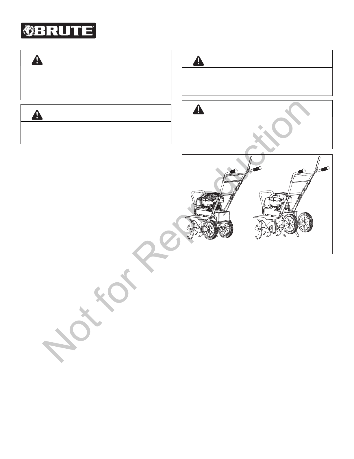
FIGURE 2
Tail mount casting allows tiller to be in two dierent positions:
working and transport. When transitioning from working
position into transport position, or vice versa, be careful of the
breach between the upper and lower tail mount casting to avoid
pinching hazards.
Transport Position
Working Position
Not for Reproduction
Loading ...
Loading ...
Loading ...