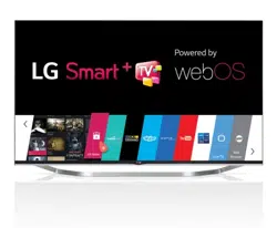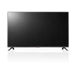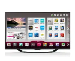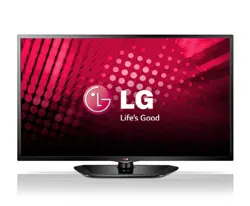
Life's Good
i!ii[;'
_,_E_ S MAMUAI_
LED
LG LED TV applies LCD screen with LED backlights.
Please read this manual carefuDly before operating
your set and retain it for future reference.
60LN5400
P/NO: MFL67651102 (1304-REVO0) www.lg.com
2 MPORTANTSAFETY NSTRUCTONS
IMPORTANT SAFETY INSTRUCTIONS
Always comply with the following precautions to avoid dangerous situations and ensure peak performance of your
)roduct.
WARNING/CAUTION
TO REDUCE THE RISK OF ELECTRIC SHOCK DO
NOT REMOVE COVER (OR BACK).
NO USER SERVICEABLE PARTS INSIDE.
REFER TO QUALIFIED SERVICE PERSONNEL.
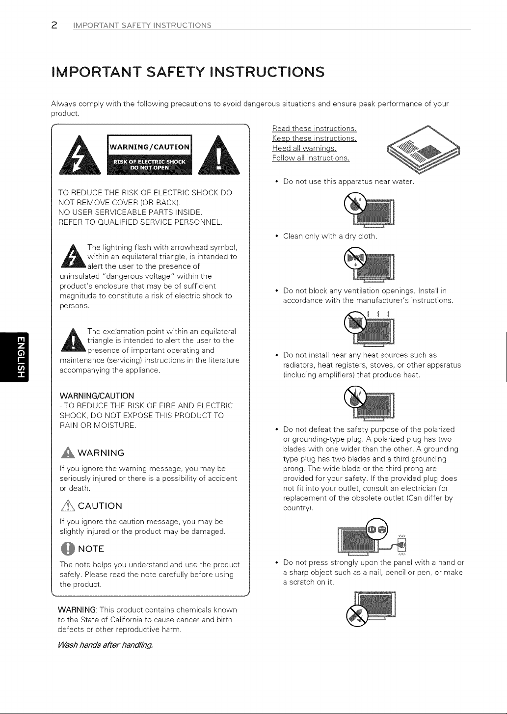
The lightning flash with arrowhead symbol,
within an equilateral triangle, is intended to
alert the user to the presence of
uninsulated "dangerous voltage" within the
product's enclosure that may be of sufficient
magnitude to constitute a risk of electric shock to
persons.
The exclamation point within an equilateral
triangle is intended to alert the user to the
presence of important operating and
maintenance (servicing) instructions in the literature
accompanying the appliance,
WARNING/CAUTION
-TO REDUCE THE RiSK OF FiRE AND ELECTRIC
SHOCK, DO NOT EXPOSE THIS PRODUCT TO
RAIN OR MOISTURE.
WARNING
tf you ignore the warning message, you may be
seriously injured or there is a possibility of accident
or death,
_:_:, CAUTION
tf you ignore the caution message, you may be
slightly injured or the product may be damaged,
NOTE
The note helps you understand and use the product
safely. Please read the note carefully before using
the product.
Read these instructions,
Keep these instructions,
Heed all warnings,
Follow all instructions,
• Do not use this apparatus near water,
• Clean only with a dry cloth.
• Do not block any ventilation openings, Install in
accordance with the manufacturer's instructions,
• Do not install near any heat sources such as
radiators, heat registers, stoves, or other apparatus
(including amplifiers) that produce heat.
• Do not defeat the safety purpose of the polarized
or grounding-type plug. A polarized plug has two
blades with one wider than the other. A grounding
type plug has two blades and a third grounding
prong. The wide blade or the third prong are
provided for your safety. If the provided plug does
not fit into your outlet, consult an electrician for
replacement of the obsolete outlet (Can differ by
country).
• Do not press strongly upon the panel with a hand or
a sharp object such as a nail, pencil or pen, or make
a scratch on it,
WARNING: This product contains chemicals known
to the State of California to cause cancer and birth
defects or other reproductive harm,
Wash hands after handling.
MPORTANTSAFETY NSTRUCTONS 3
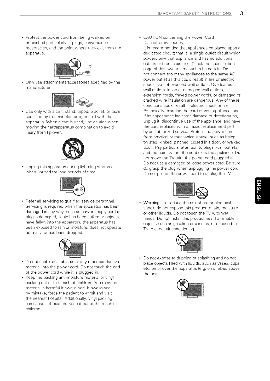
• Protect the power cord from being walked on
or pinched particularly at plugs, convenience
receptacles, and the point where they exit from the
apparatus.
d
• Only use attachments/accessories specified by the
manufacturer.
• Use only with a cart, stand, tripod, bracket, or table
specified by the manufacturer, or sold with the
apparatus. When a cart is used, use caution when
moving the cart/apparatus combination to avoid
injury from tip-over.
• Unplug this apparatus during lightning storms or
when unused for long periods of time.
CAUTION concerning the Power Cord
(Can differ by country):
It is recommended that appliances be placed upon a
dedicated circuit; that is, a single outlet circuit which
powers only that appliance and has no additional
outlets or branch circuits. Check the specification
page of this owner's manual to be certain. Do
not connect too many appliances to the same AC
power outlet as this could result in fire or electric
shock. Do not overload wall outlets. Overloaded
wall outlets, loose or damaged wall outlets,
extension cords, frayed power cords, or damaged or
cracked wire insulation are dangerous. Any of these
conditions could result in electric shock or fire.
Periodically examine the cord of your appliance, and
if its appearance indicates damage or deterioration,
unplug it, discontinue use of the appliance, and have
the cord replaced with an exact replacement part
by an authorized service. Protect the power cord
from physical or mechanical abuse, such as being
twisted, kinked, pinched, closed in a door, or walked
upon. Pay particular attention to plugs, wall outlets,
and the point where the cord exits the appliance. Do
not move the TV with the power cord plugged in.
Do not use a damaged or loose power cord. Be sure
do grasp the plug when unplugging the power cord.
Do not pull on the power cord to unplug the TV.
• Refer all servicing to qualified service personnel.
Servicing is required when the apparatus has been
damaged in any way, such as power-supply cord or
plug is damaged, liquid has been spilled or objects
have fallen into the apparatus, the apparatus has
been exposed to rain or moisture, does not operate
normally, or has been dropped.
Warning - To reduce the risk of fire or electrical
shock, do not expose this product to rain, moisture
or other liquids. Do not touch the TV with wet
hands. Do not install this product near flammable
objects such as gasoline or candles, or expose the
TV to direct air conditioning.
• Do not stick metal objects or any other conductive
material into the power cord. Do not touch the end
of the power cord while it is plugged in.
• Keep the packing anti-moisture material or vinyl
packing out of the reach of children. Anti-moisture
material is harmful if swallowed. If swallowed
by mistake, force the patient to vomit and visit
the nearest hospital. Additionally, vinyl packing
can cause suffocation. Keep it out of the reach of
children.
Do not expose to dripping or splashing and do not
place objects filled with liquids, such as vases, cups,
etc. on or over the apparatus (e.g. on shelves above
the unit).
4 MPORTANT SAFETY NSTRUCT ONS
Grounding
(Except for devices which are not grounded.)
Ensure that you connect the earth ground wire to
prevent possible electric shock (i.e. a TV with a
three-prong grounded AC plug must be connected
to a three-prong grounded AC outlet). If grounding
methods are not possible, have a qualified
electrician install a separate circuit breaker. Do not
try to ground the unit by connecting it to telephone
wires, lightening rods, or gas pipes.
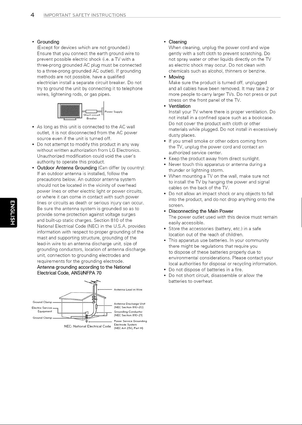
Power Supply
As long as this unit is connected to the AC walt
outlet, it is not disconnected from the AC power
source even if the unit is turned off.
Do not attempt to modify this product in any way
without written authorization from LG Electronics.
Unauthorized modification could void the user's
authority to operate this product.
Outdoor Antenna Grounding (Can differ by country):
If an outdoor antenna is installed, follow the
precautions below. An outdoor antenna system
should not be located in the vicinity of overhead
power lines or other electric light or power circuits,
or where it can come in contact with such power
lines or circuits as death or serious injury can occur.
Be sure the antenna system is grounded so as to
provide some protection against voltage surges
and built-up static charges. Section 810 of the
National Electrical Code (NEC) in the U.S.A. provides
information with respect to proper grounding of the
mast and supporting structure, grounding of the
lead-in wire to an antenna discharge unit, size of
grounding conductors, location of antenna discharge
unit, connection to grounding electrodes and
requirements for the grounding electrode.
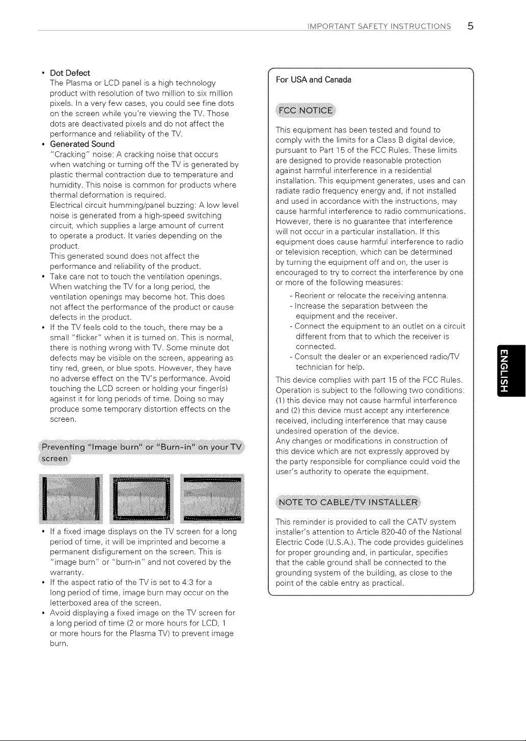
Antenna grounding according to the National
Electrical Code, ANSl/NFPA 70
• Cleaning
When cleaning, unplug the power cord and wipe
gently with a soft cloth to prevent scratching. Do
not spray water or other liquids directly on the TV
as electric shock may occur. Do not clean with
chemicals such as alcohol, thinners or benzine.
• Moving
Make sure the product is turned off, unplugged
and all cables have been removed. It may take 2 or
more people to carry larger TVs. Do not press or put
stress on the front panel of the TV.
• Ventilation
Install your TV where there is proper ventilation. Do
not install in a confined space such as a bookcase.
Do not cover the product with cloth or other
materials while plugged. Do not install in excessively
dusty places.
• If you smell smoke or other odors coming from
the TV, unplug the power cord and contact an
authorized service center.
• Keep the product away from direct sunlight.
• Never touch this apparatus or antenna during a
thunder or lightning storm.
• When mounting a TV on the wall, make sure not
to install the TV by hanging the power and signal
cables on the back of the TV.
• Do not allow an impact shock or any objects to fall
into the product, and do not drop anything onto the
screen,
• Disconnecting the Main Power
The power outlet used with this device must remain
easily accessible.
• Store the accessories (battery, etc.) in a safe
location out of the reach of children.
• This apparatus use batteries. In your community
there might be regulations that require you
to dispose of these batteries properly due to
environmental considerations. Please contact your
local authorities for disposal or recycling information.
• Do not dispose of batteries in a fire.
• Do not short circuit, disassemble or allow the
batteries to overheat.
Ground Clamp Antenna Discharge Unit
Electric Service (NEC Section 810-20)
Equipment [ Grounding Conductor
(NEC Section 810-21)
+ Power Service Grounding
NEC: National Electrical Code Electrode System
(NEC Art 250 r Part H)
MPORTANTSAFETY NSTRUCTONS 5
• Dot Defect
The Plasma or LCD panet is a high technology
product with resolution of two million to six million
pixels. In a very few cases, you could see fine dots
on the screen while you're viewing the TV. Those
dots are deactivated pixets and do not affect the
performance and reliability of the TV.
• Generated Sound
"Cracking" noise: A cracking noise that occurs
when watching or turning off the TV is generated by
plastic thermal contraction due to temperature and
humidity. This noise is common for products where
thermal deformation is required.
Electrical circuit humming/panel buzzing: A low level
noise is generated from a high-speed switching
circuit, which supplies a large amount of current
to operate a product. It varies depending on the
product.
This generated sound does not affect the
performance and reliability of the product.
• Take care not to touch the ventilation openings.
When watching the TV for a long period, the
ventilation openings may become hot. This does
not affect the performance of the product or cause
defects in the product.
• If the TV feels cold to the touch, there may be a
small "flicker" when it is turned on. This is normal,
there is nothing wrong with TV. Some minute dot
defects may be visible on the screen, appearing as
tiny red, green, or blue spots. However, they have
no adverse effect on the TV's performance. Avoid
touching the LCD screen or holding your finger(s)
against it for long periods of time, Doing so may
produce some temporary distortion effects on the
screen.
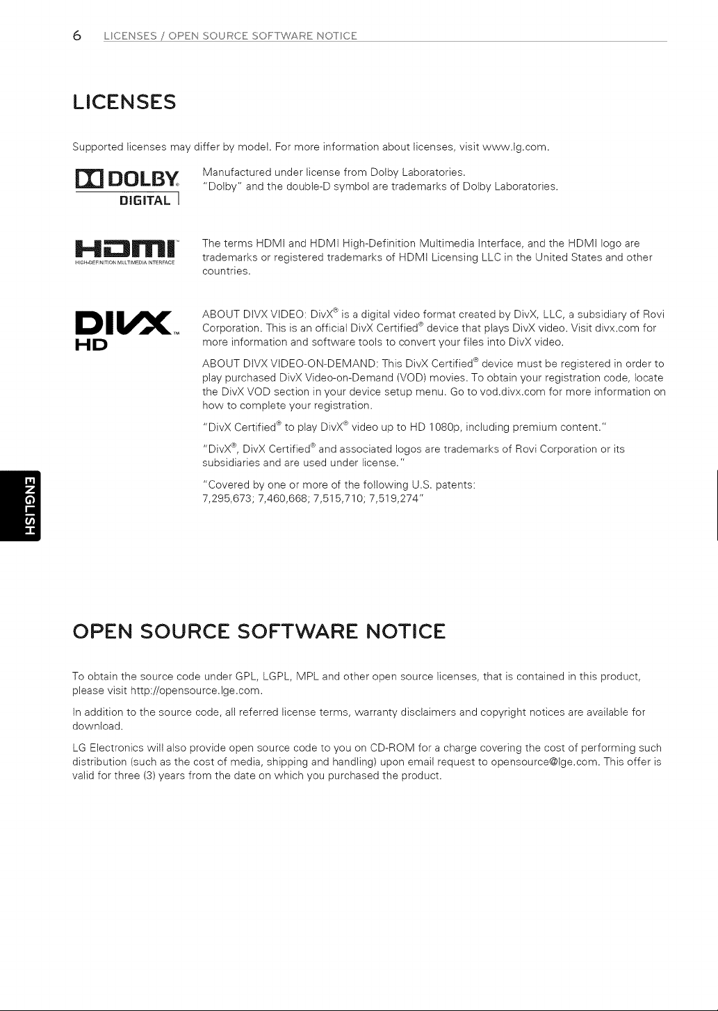
• If a fixed image displays on the TV screen for a long
period of time, it wilt be imprinted and become a
permanent disfigurement on the screen. This is
"image burn" or "burn-in" and not covered by the
warranty.
• If the aspect ratio of the TV is set to 4:3 for a
long period of time, image burn may occur on the
letterboxed area of the screen.
• Avoid displaying a fixed image on the TV screen for
a long period of time (2 or more hours for LCD, 1
or more hours for the Plasma TV) to prevent image
burn.
For USA and Canada
This equipment has been tested and found to
comply with the limits for a Class B digital device,
pursuant to Part 15 of the FCC Rules. These limits
are designed to provide reasonable protection
against harmful interference in a residential
installation. This equipment generates, uses and can
radiate radio frequency energy and, if not installed
and used in accordance with the instructions, may
cause harmful interference to radio communications.
However, there is no guarantee that interference
will not occur in a particular installation. If this
equipment does cause harmful interference to radio
or television reception, which can be determined
by turning the equipment off and on, the user is
encouraged to try to correct the interference by one
or more of the following measures:
- Reorient or relocate the receiving antenna.
- Increase the separation between the
equipment and the receiver.
- Connect the equipment to an outlet on a circuit
different from that to which the receiver is
connected.
- Consult the dealer or an experienced radioFV
technician for help.
This device complies with part 15 of the FCC Rules.
Operation is subject to the following two conditions:
(1) this device may not cause harmful interference
and (2) this device must accept any interference
received, including interference that may cause
undesired operation of the device.
Any changes or modifications in construction of
this device which are not expressly approved by
the party responsible for compliance could void the
user's authority to operate the equipment.
This reminder is provided to call the CATV system
installer's attention to Article 820-40 of the National
Electric Code (U.S.A.). The code provides guidelines
for proper grounding and, in particular, specifies
that the cable ground shall be connected to the
grounding system of the building, as close to the
point of the cable entry as practical.
6 L CENSES / OPEN SOURCE SC)FrTWARE NOTCE
LICENSES
Supported licenses may differ by model. For more information about licenses, visit www.lg.com.
m DOLBY
DIGITAL I
Manufactured under license from Dolby Laboratories.
"Dolby" and the doubte-D symbol are trademarks of Dolby Laboratories.
H;;:llrr||
HIGH-DEFINITION MULTIMEDIA INTEREACE
The terms HDMI and HDMI High-Definition Multimedia Interface, and the HDMI logo are
trademarks or registered trademarks of HDMI Licensing LLC in the United States and other
countries.
HD
ABOUT DIVX VIDEO: DivX ® is a digital video format created by DivX, LLC, a subsidiary of Rovi
Corporation. This is an official DivX Certified ® device that plays DivX video. Visit divx.com for
more information and software tools to convert your files into DivX video.
ABOUT DIVX VIDEO-ON-DEMAND: This DivX Certified ® device must be registered in order to
play purchased DivX Video-on-Demand (VOD) movies. To obtain your registration code, locate
the DivX VOD section in your device setup menu. Go to vod.divx.com for more information on
how to complete your registration.
"DivX Certified ® to play DivX® video up to HD 1080p, including premium content."
"DivX ®, DivX Certified ®and associated Iogos are trademarks of Rovi Corporation or its
subsidiaries and are used under license."
"Covered by one or more of the following U.S. patents:
7,295,673; 7,460,668; 7,515,710; 7,519,274"
OPEN SOURCE SOFTWARE NOTICE
To obtain the source code under GPL, LGPL, MPL and other open source licenses, that is contained in this product,
please visit http://opensource,lge,com,
In addition to the source code, all referred license terms, warranty disclaimers and copyright notices are available for
download,
LG Electronics will also provide open source code to you on CD-ROM for a charge covering the cost of performing such
distribution (such as the cost of media, shipping and handling) upon email request to opensource@lge,com, This offer is
valid for three (3) years from the date on which you purchased the product,
TABLE OFr CONTENTS 7
TABLE OF CONTENTS
2 IMPORTANT SAFETY INSTRUCTIONS 26 REMOTE CONTROL
6 LICENSES
6 OPEN SOURCE SOFTWARE NOTICE
7 TABLE OF CONTENTS
8 INSTALLATION PROCEDURE
8 ASSEMBLING AND PREPARING
s
10
11
12
13
13
14
16
17
Unpacking
Optional Extras
Parts and Buttons
Lifting and moving the TV
Setting up the TV
- Attaching the stand
- Mounting on a table
- Mounting on a wall
- Tidying cables
MAKING CONNECTIONS18
18 Connecting to an antenna or cable
19 Connecting to a HD receiver, DVD Player, or VCR
19 - HDMI Connection
20 - Connecting to a mobile phone
21 - Component Connection
22 - Composite Connection
23 Connecting a PC
23 - HDMI Connection
24 Connecting to an Audio System
24 - Digital Optical Audio Connection
25 Connecting a USB Device
28 WATCHING TV
28 Turning the TV on for the first time
29 USING THE USER GUIDE
30 SPECIFICATIONS
32 MAINTENANCE
32
32
32
Cleaning Your TV
- Screen, frame, cabinet and stand
- Power cord
32 TROUBLESHOOTING
33 EXTERNAL CONTROL DEVICE SETUP
......NOTE
• image shown may differfrom your TV.
• Your TV's OSD (On Screen Display) may differ
slightlyfrom that shown in this manual.
• The available menus and options may differfrom
the input source or product model that you are
using.
• New features may be added to thisTVin the
future,
8 NSTALL/_{TONPROCEDURE/ ASSEMBL NG AND PREPAR NG
INSTALLATION PROCEDURE
1 Open the package and make sure all the accessories are included.
2 Attach the stand to the TV set.
3 Connect an external device to the TV set.
ASSEMBLING AND PREPARING
Unpacking
Check your product box for the following items. If there are any missing accessories, contact the local dealer where you
purchased your product. The illustrations in this manual may differ from the actual product and item.
...._ CAUT ON
• Do not use any unapproved items to ensure the safety and product life span.
• Any damages or injuries by using unapproved items are not covered by the warranty.
S°rne d P t ! is let at! u lee n tie m o v .........................................................................................,/
......O NOTE
• The items supplied with your product may vary depending on the model.
• Product specifications or contents of this manual may be changed without prior notice due to upgrade of product
functions.
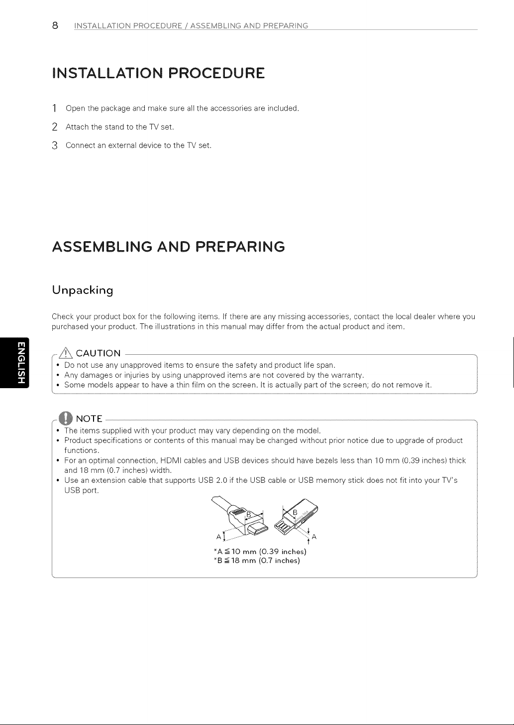
• For an optimat connection, HDMI cables and USB devices should have bezels less than 10 mm (0.39 inches) thick
and 18 mm (0.7 inches) width.
• Use an extension cable that supports USB 2.0 if the USB cable or USB memory stick does not fit into your TV's
USB port.
_A < 10 mm (0.39 inches)
_B -<18 mm (0.7 inches)
ASSEMBLNGANDPREPARNG c)
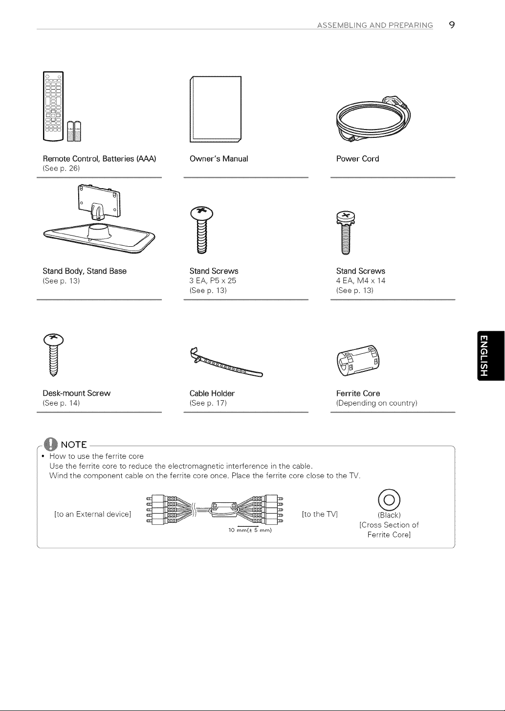
Remote Control, Batteries (AAA)
(See p. 26)
Stand Body, Stand Base
(See p. 13)
Owner's Manual
Stand Screws
3 EA, P5 x 25
(See p. 13)
Power Cord
Stand Screws
4EA, M4x 14
(See p. 13)
Desk-mount Screw Cable Holder Ferrite Core
(See p. 14) (See p. 17) (Depending on country)
..... NOTE
• How to use the ferrite core
Use the ferrite core to reduce the electromagnetic interference in the cable,
Wind the component cabte on the ferrite core once, Place the ferrite core close to the TV.
,toanExte na,dev,oel ,totheTVl
10 mm(± 5_mm)
©
(Black)
[Cross Section of
Ferrite Core]
10 ASSEMBL NG AND PREPAR NG
Optional Extras
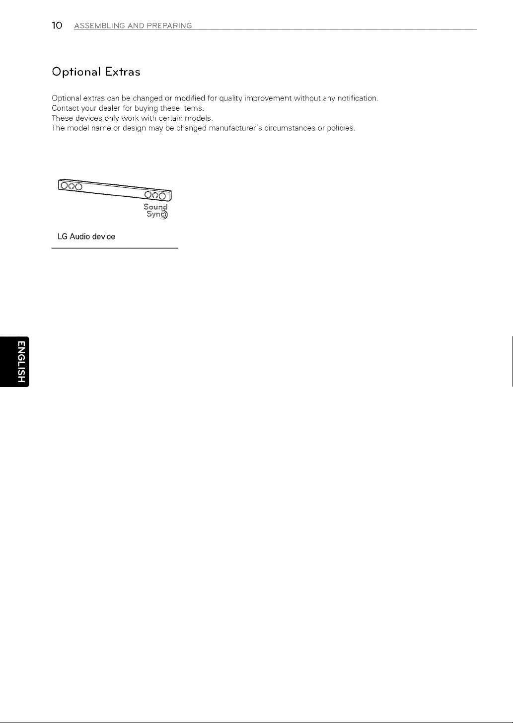
Optional extras can be changed or modified for quality improvement without any notification.
Contact your dealer for buying these items.
These devices only work with certain models.
The model name or design may be changed manufacturer's circumstances or policies.
Sound
LG Audio device
ASSEMBLNGANDPREPARNG 11
Parts and Buttons
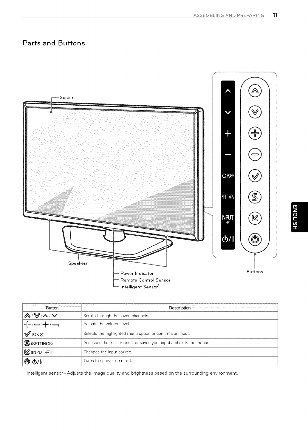
_Screen
Speakers
Power Indicator
Remote Control Sensor
Intelligent Sensor 1
q9
(9
(9
@
@
@
\
Buttons
ButtOn Description
/ _ (/_. / V) Scrolls through the saved channels.
@ / _ (+ / m) Adjusts the volume level.
(OK®) Selects the highlighted menu option or confirms an input.
(SETTINGS) Accesses the main menus, or saves your input and exits the menus.
(INPUT -El ) Changes the input source.
@ ((_/I) Turns the power on or off.
1 intelligent sensor - Adjusts the image quality and brightness based on the surrounding environment.
12 ASSEMBL NG AND PREPAR NG
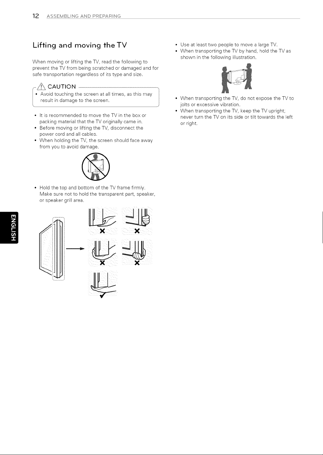
Lifting and moving theTV
When moving or lifting the TV, read the following to
prevent the TV from being scratched or damaged and for
safe transportation regardless of its type and size.
,_i_ CAUTION ..............................................................................................................................................................................
• Avoid touching the screen at all times, as this may
result in damage to the screen.
It is recommended to move the TV in the box or
packing material that the TV originally came in.
Before moving or lifting the TV, disconnect the
power cord and all cables.
When holding the TV, the screen should face away
from you to avoid damage.
0
Hold the top and bottom of the TV frame firmly.
Make sure not to hold the transparent part, speaker,
or speaker grill area.
I
X
• Use at least two people to move a large TV.
• When transporting the TV by hand, hold the TV as
shown in the following illustration.
• When transporting the TV, do not expose the TV to
jolts or excessive vibration.
• When transporting the TV, keep the TV upright;
never turn the TV on its side or tilt towards the left
or right.
ASSEMBLNGANDPAEPAANG 13
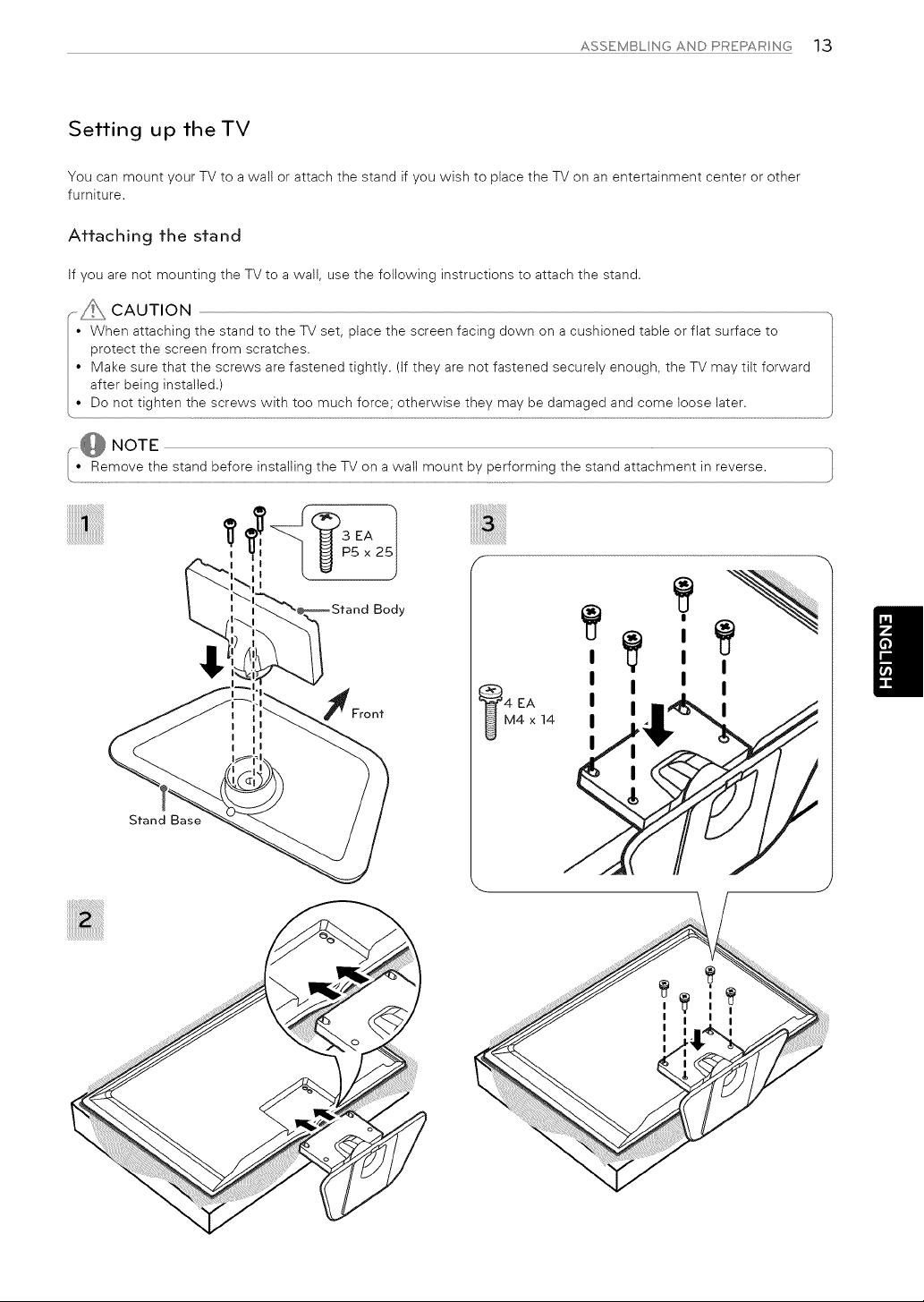
Setting up theTV
You can mount your TV to a wall or attach the stand if you wish to place the TV on an entertainment center or other
furniture.
Affaching fhe sfand
If you are not mounting the TV to a wall, use the following instructions to attach the stand.
CAUTION
• When attaching the stand to the TV set, place the screen facing down on a cushioned table or flat surface to
protect the screen from scratches.
• Make sure that the screws are fastened tightly. (If they are not fastened securely enough, the TV may tilt forward
after being installed.)
I" Do not tighten ..................................................................
Stand Base
Body
4 EA
M4 x 14
I I I
I
I
I
I
I
I
I
I
14 ASSEMBL NG AND PREPAR NG
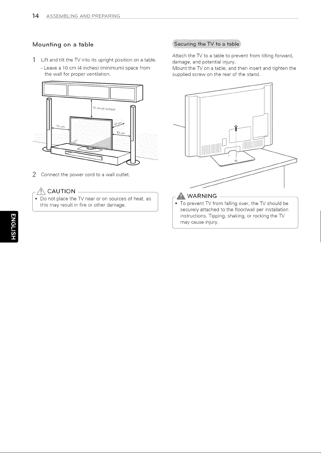
Mounfing on a fable
1 Lift and tilt the TV into its upright position on a table.
- Leave a 10 cm (4 inches) (minimum) space from
the walt for proper ventilation.
2 Connect the power cord to a wall outlet.
Attach the TV to a table to prevent from tilting forward,
damage, and potential injury.
Mount the TV on a table, and then insert and tighten the
supplied screw on the rear of the stand.
_ WARNING
• To prevent TV from failing over the TV should be
securely attached to the floor/wall per installation
instructions Tipping shaking or rocking the TV
may cause injury
ASSEMBLNGANDPREPARNG 15
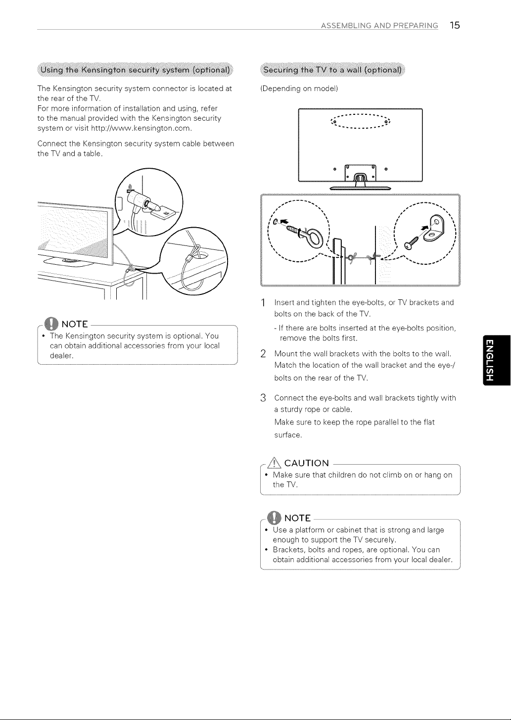
The Kensington security system connector is located at
the rear of the TV.
For more information of installation and using, refer
to the manual provided with the Kensington security
system or visit http://www.kensington.com.
Connect the Kensington security system cable between
the TV and a table.
(Depending on model)
o-" ........ --4
to o_
_. ......... °-"
jr
s I
1 Insert and tighten the eye-bolts, or TV brackets and
bolts on the back of the TV.
- If there are bolts inserted at the eye-bolts position,
remove the bolts first.
2 Mount the wall brackets with the bolts to the wall.
Match the location of the wall bracket and the eye-/
bolts on the rear of the TV.
Connect the eye-bolts and wall brackets tightly with
a sturdy rope or cable.
Make sure to keep the rope parallel to the flat
surface.
NOTE
• Use a platformor cabinetthatisstrongand large
enough tosupportthe TV securely.
• Brackets,boltsand ropes,are optional.You can
I blai_ I d_ilionai II le s_Ir!l s !r Imy o ul !llli deal I
16 ASSEMBL NG AND PREPAR NG
Mounting on a wall
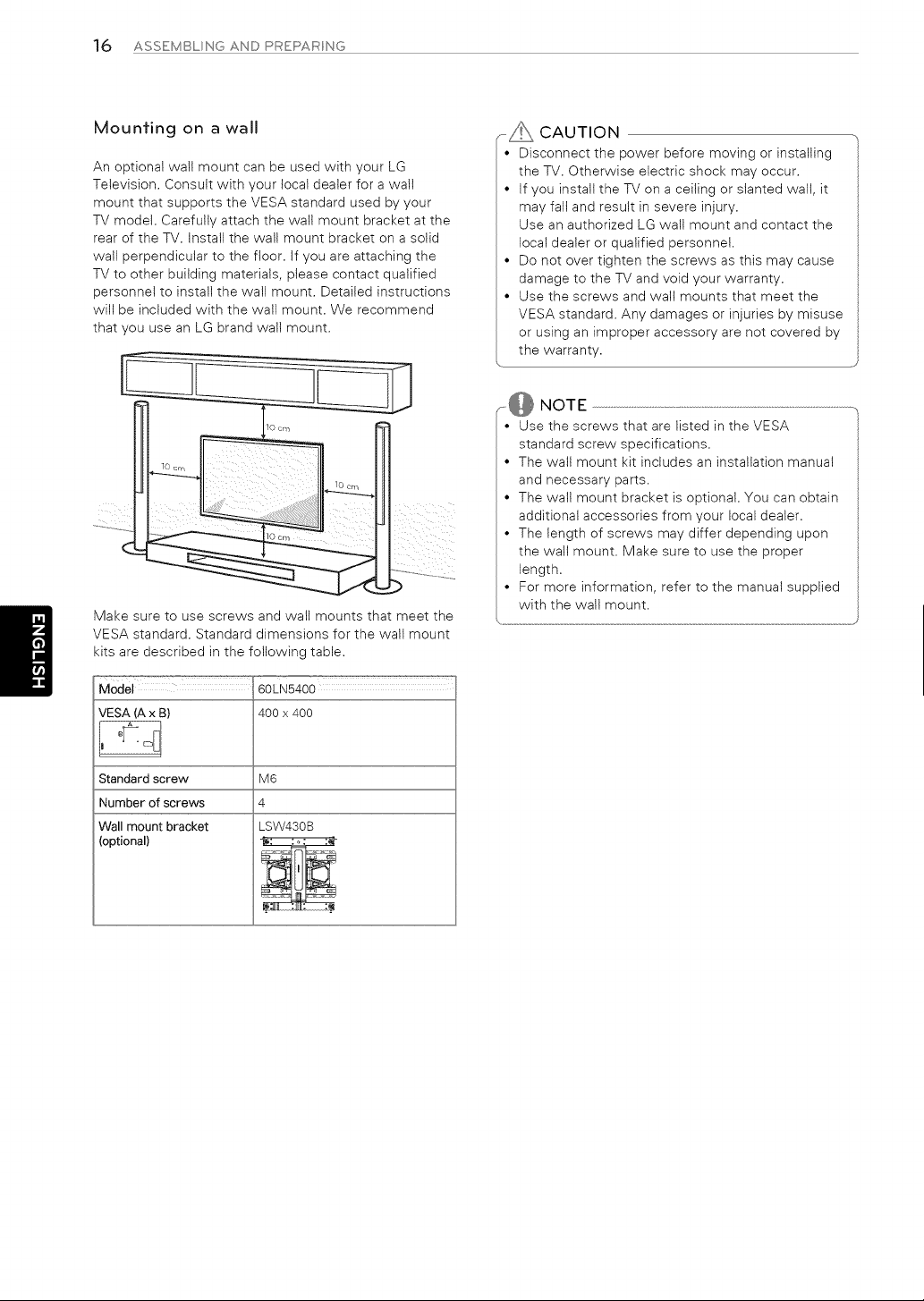
An optional wall mount can be used with your LG
Television. Consult with your local dealer for a wall
mount that supports the VESA standard used by your
TV model. Carefully attach the wall mount bracket at the
rear of the TV. Install the wall mount bracket on a solid
wall perpendicular to the floor. If you are attaching the
TV to other building materials, please contact qualified
personnel to install the walt mount. Detailed instructions
will be included with the walt mount. We recommend
that you use an LG brand wall mount.
......._, CAUTION
• Disconnectthe power beforemoving or installing
theTV, Otherwise electricshock may occur,
• Ifyou installtheTV on a ceilingor slantedwall,it
may falland resultinsevereinjury,
Use an authorizedLG wallmount and contactthe
localdealeror qualifiedpersonnel,
• Do not over tightenthe screws as thismay cause
damage to theTV and voidyour warranty,
• Use the screws and wallmounts thatmeet the
VESA standard,Any damages or injuriesby misuse
or usingan improperaccessoryare notcovered by
the warranty.
Make sure to use screws and wall mounts that meet the
VESA standard. Standard dimensions for the wall mount
kits are described in the following table.
Model 60LN5400
VESA (A x B) 400 x 400
M6
4
LSW430B
Standard screw
Number of screws
Wall mount bracket
(optional}
,,@ NOTE
• Use the screws thatare listedinthe VESA
standardscrew specifications,
• The wallmount kitincludesan installationmanual
and necessaryparts,
• The wallmount bracketisoptional,You can obtain
additionalaccessoriesfrom your localdealer,
• The lengthofscrews may differdepending upon
the wallmount, Make sure to use the proper
length,
• For more information,refertothe manual supplied
with the wall mount.
ASSEMBL NG AND PREPAR NG 1"7
Tidying cables
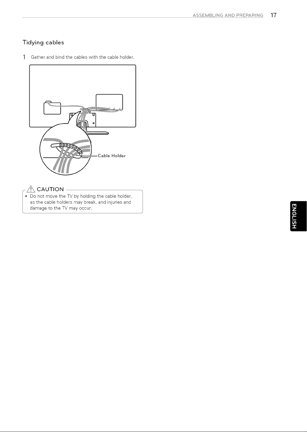
1 Gather and bind the cables with the cable holder.
_L Cable Holder
CAUTION
• Do not move theTV by holdingthe cableholder,
as the cableholdersmay break,and injuriesand
damage tothe TV may occur,
18 MAKNGCONNECTONS
MAKING CONNECTIONS
You can connect various external devices to the TV. Supported external devices are: HD receivers, DVD players, VCRs,
audio systems, USB storage devices, PC, gaming devices, and other external devices. For more information on external
device's connection, refer to the manual provided with each device.
NOTE
• If you record a TV program on a DVD recorder or VCR, make sure to connect the TV signal input cable to the TV
through a DVD recorder or VCR. For more information about recording, refer to the manual provided with the
connected device.
• The external device connections shown may differ slightly from illustrations in this manual.
• Connect external devices to the TV regardless about the order of the TV port.
• If you connect a gaming device to the TV, use the cable supplied with the gaming device.
• Refer to the external equipment's manual for operating instructions.
Connecting to an antenna or cable
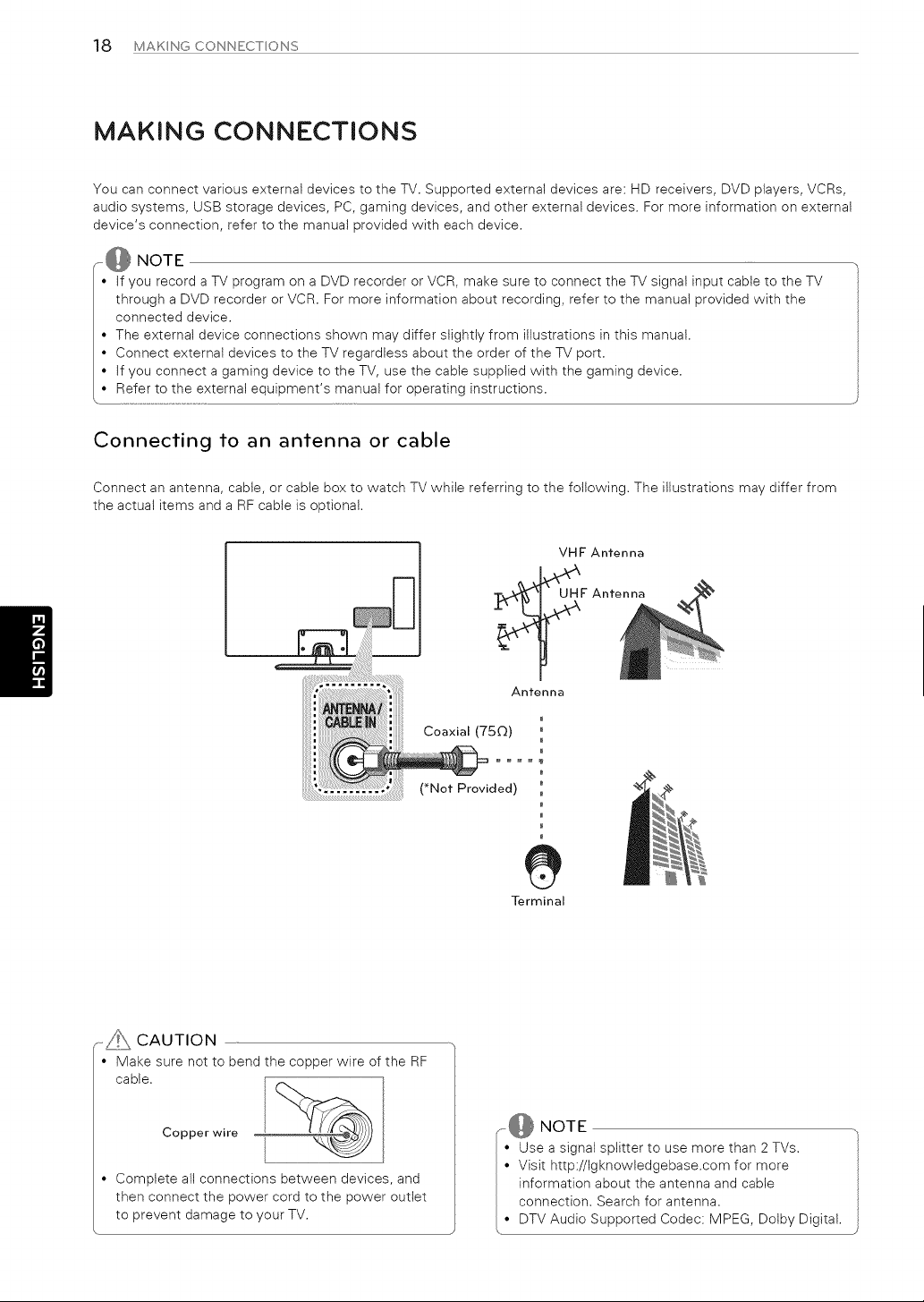
Connect an antenna, cable, or cable box to watch TV while referring to the following. The illustrations may differ from
the actual items and a RF cable is optional.
VHF Antenna
_F Antenna
L.oaxlal [/3_2)
di ":
• )
Terminal
,-_ CAUTION
• Make sure notto bend the copper wire ofthe RF
cable,
Copper wire
• Complete all connections between devices, and
then connect the power cord to the power outlet
to prevent damage to your TV.
NOTE
• Use a signalsplitterto use more than 2 TVs,
• Visithttp://Igknowledgebase,comformore
informationabout theantenna and cable
connection,Search forantenna,
• DTV Audio Supported Codec: MPEG, Dolby Digital,
MAKNGCONNECTONS 19
Connecting to a HD receiver, DVD Player, or VCR
Connect a HD receiver, DVD Player, or VCR to the TV and select an appropriate input mode.
HDMI Connection
HDMI is the best way to connect a device,
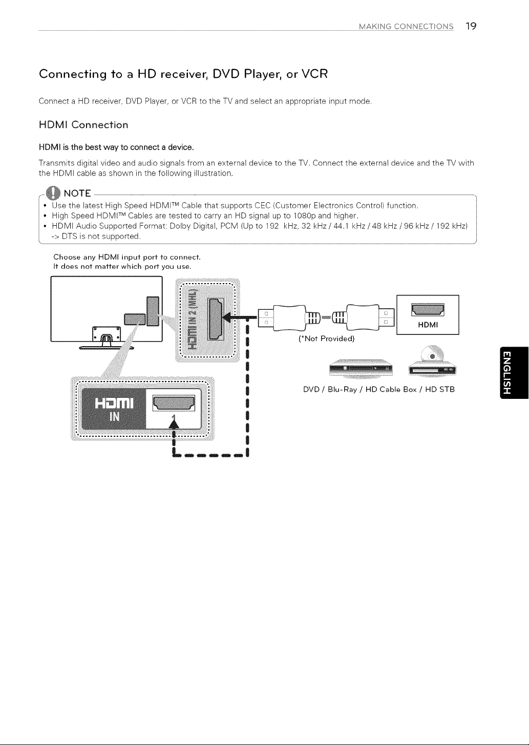
Transmits digital video and audio signals from an external device to the TV. Connect the external device and the TV with
the HDMi cable as shown in the following illustration.
i@ NOTE TM
Use the latest High Speed HDMt Cable that supports CEC (Customer Electronics Control) function.
High Speed HDMI TM Cables are tested to carry an HD signal up to 1080p and higher.
I' HDMlAudioSupportedFormat:DolbyDigitaI, PCM (Up to192 kHz, 32kHz/44.1 kHz/48kHz/96kHz/192kHz)
( -> DTS is not supported ..............................................................................................................................................................................................................................................................................................................................................................................................................................................................................................................
Choose any HDMI input port to connect,
It does not matter which port you use.
I
I
|
I
I
I
I
I
I
I
HDMI
(_Not Provided)
DVD / Blu-Ray / HD Cable Box / HD STB
20 MAKNGCONNECTONS
Connecting to a mobile phone
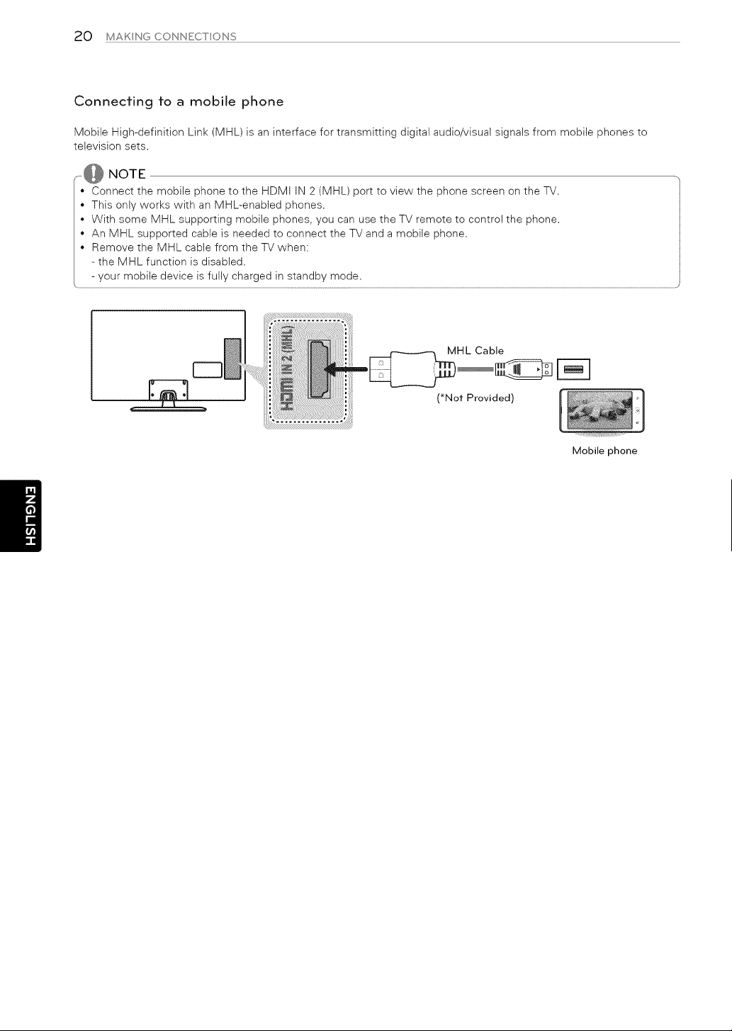
Mobile High-definition Link (MHL) is an interface for transmitting digital audio/visual signals from mobile phones to
television sets.
NOTE
• Connect the mobile phone tothe HDMI IN 2 (MHL) portto view the phone screen on the TV.
• Thisonlyworks with an MHL-enabled phones.
• With some MHL supportingmobile phones, you can use theTV remote to controlthe phone.
• An MHL supportedcableisneeded to connect theTV and a mobile phone.
• Remove the MHL cablefrom the TV when:
- the MHL functionisdisabled.
- your mobile deviceisfullycharged in standbymode.
MHL Cable
(*Not Provided) i o
Mobile phone
MAKNGCONNECTONS 21
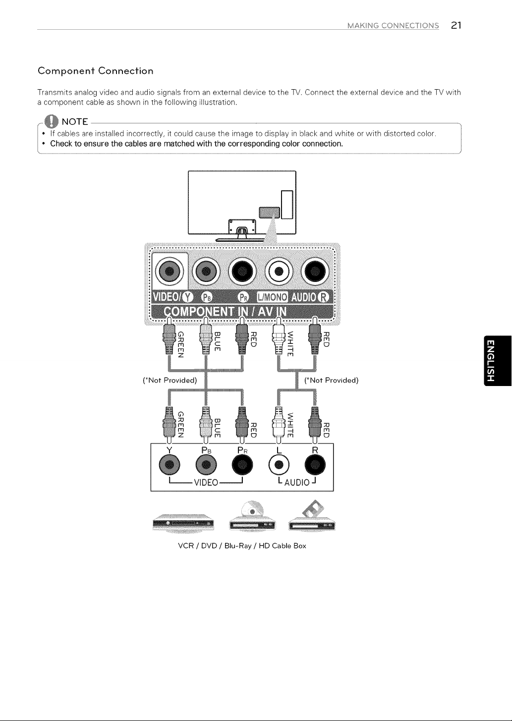
Component Connection
Transmits analog video and audio signals from an external device to the TV. Connect the externat device and the TV with
a component cabte as shown in the following illustration.
@NOTE
• If cables are installed incorrectly, it could cause the image to display in black and white or with distorted color.
........,CheG ureth ma! w!!h!he€°rren € ect!°n:...................................................................................................................................................................................................................................................J
(*Not Provided) (*Not Provided)
Y PB PR
--VIDEO_
L R
®
LAUDIO J
m
_D
..................._{¢,;#(i:i!_,_
VCR / DVD / Blu-Ray / HD Cable Box
22 MAKNG CONNECT ONS
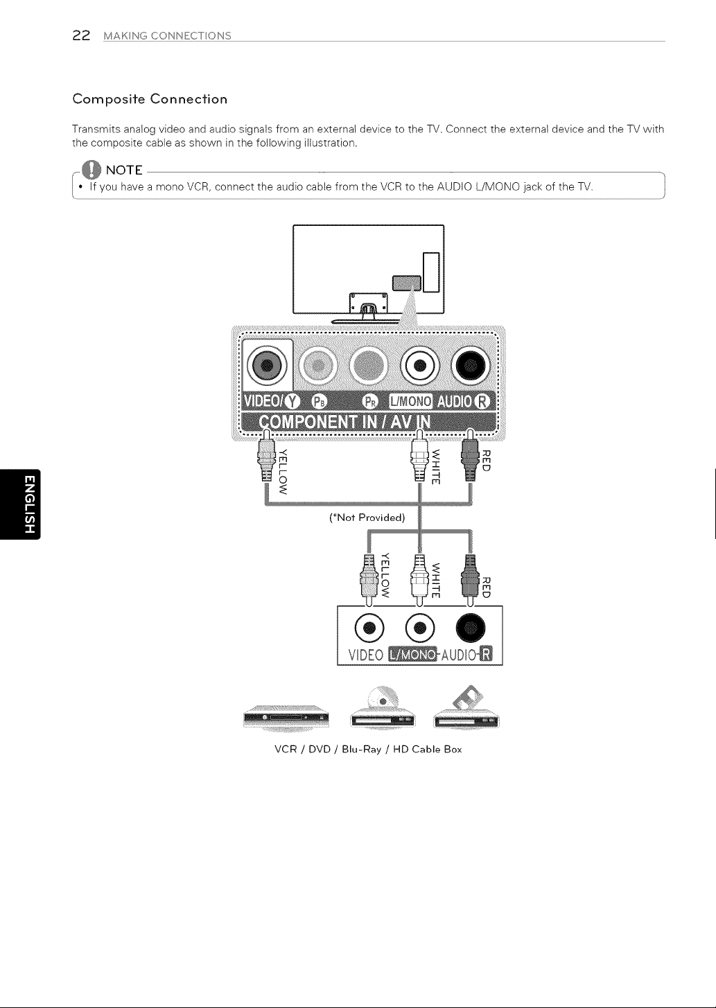
Composite Connection
Transmits analog video and audio signals from an external device to the TV. Connect the external device and the TV with
the composite cable as shown in the following illustration.
,-@ NOTE
If have the audio cable from the VCR the AUDIO of the TV.
you
a mono VCR, connect to L/MONO
jack
(*Not Provided)
®®
VIDEO_AUDI0_
VCR / DVD / Blu-Ray / HD Cable Box
MAKNGCONNECTONS23
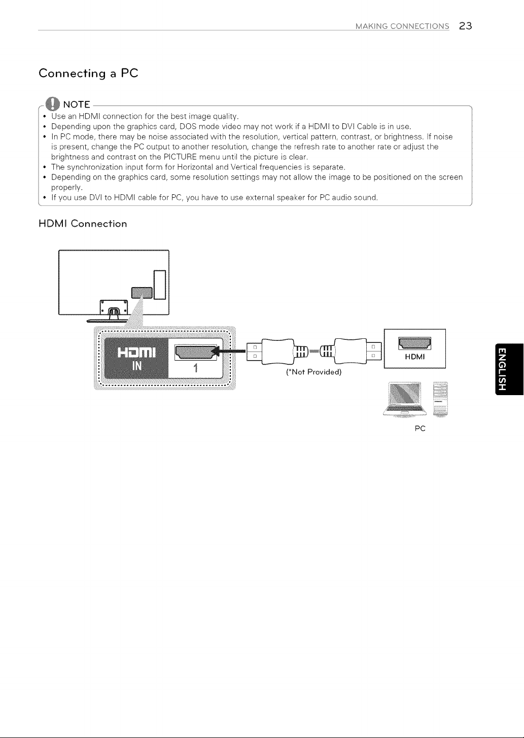
Connecting a PC
,@ NOTE
• Use an HDMi connection for the best image quality.
• Depending upon the graphics card, DOS mode video may not work if a HDMi to DVi Cabte is in use.
• in PC mode, there may be noise associated with the resolution, vertical pattern, contrast, or brightness, if noise
is present, change the PC output to another resolution, change the refresh rate to another rate or adjust the
brightness and contrast on the PICTURE menu until the picture is dear.
• The synchronization input form for Horizontal and Vertical frequencies is separate.
• Depending on the graphics card, some resolution settings may not allow the image to be positioned on the screen
properly.
• if you use DVi to HDMi cabte for PC, you have to use external speaker for PC audio sound.
HDMI Connection
(*Not Provided)
HDMm
PC
24 MAKNG CONNECTONS
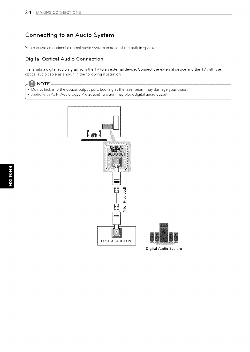
Connecting to an Audio System
You can use an optional external audio system instead of the built-in speaker,
Digifal Opfical Audio Connecfion
Transmits a digital audio signal from the TV to an external device, Connect the external device and the TV with the
optical audio cable as shown in the following illustration.
@NOTE
• Do not look into the optical output port. Looking at the laser beam may damage your vision.
• Audio with ACP (Audio Copy Protection) function may block digital audio output.
z
/l;ii!i!_iiii_iiii,ii
OPTICAL AUDIO iN
Digital Audio System
MAKNGCONNECTONS25
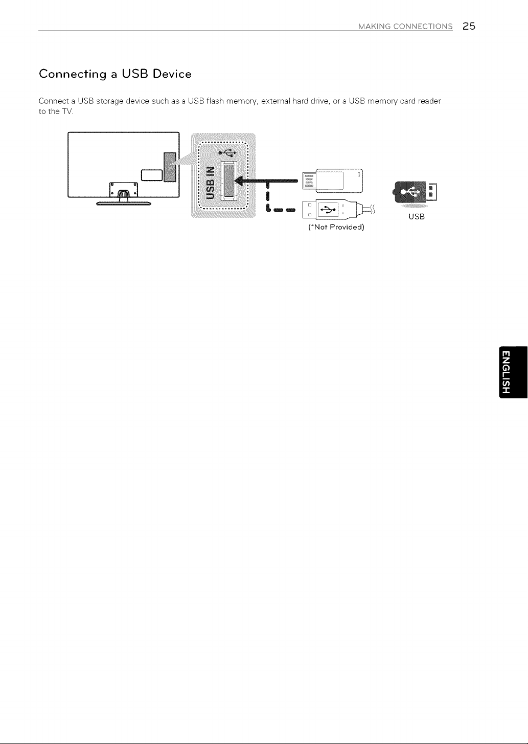
Connecting a USB Device
Connect a USB storage device such as a USB flash memory, external hard drive, or a USB memory card reader
to the TV.
(*Not Provided)
USB
2,6 REMOTECONTROL
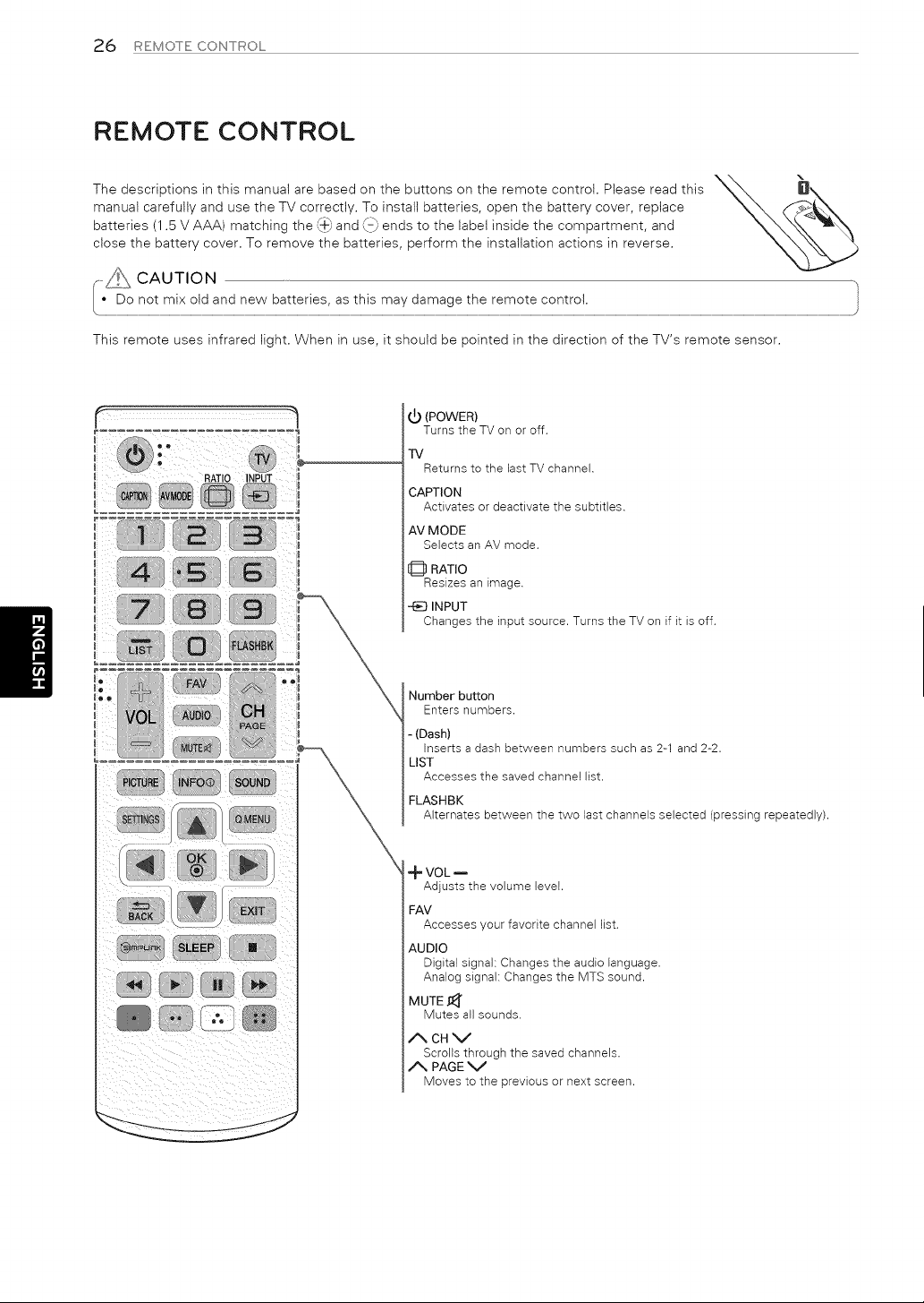
REMOTE CONTROL
The descriptions in this manual are based on the buttons on the remote control. Please read this
manual carefully and use the TV correctly. To install batteries, open the battery cover, replace
Sm F m
batteries (1.5 V AAA) matching the {+_,and \_ ends to the label inside the compartment, and
close the battery cover. To remove the batteries, perform the installation actions in reverse.
This remote uses infrared light. When in use, it should be pointed in the direction of the TV's remote sensor.
t_ (POWER)
Turns the TV on or off.
TV
Returns to the last TV channel.
CAPTION
Activates or deactivate the subtitles.
AV MODE
Selects an AV mode.
t_ RATIO
Resizes an image.
-t_ INPUT
Changes the input source. Turns the TV on if it is off.
Number button
Enters numbers.
- (Dash)
Inserts a dash between numbers such as 2-1 and 2-2.
LIST
Accesses the saved channel list.
FLASHBK
Alternates between the two last channels selected (pressing repeatedly).
•_ VOL
Adjusts the volume level.
FAV
Accesses your favorite channel list.
AUDIO
Digital signal: Changes the audio language.
Analog signal: Changes the MTS sound.
MUTE 11_
Mutes all sounds.
ACHV
Scrolls through the saved channels.
A PAGE V
Moves to the previous or next screen.
REMOTECONTROL27
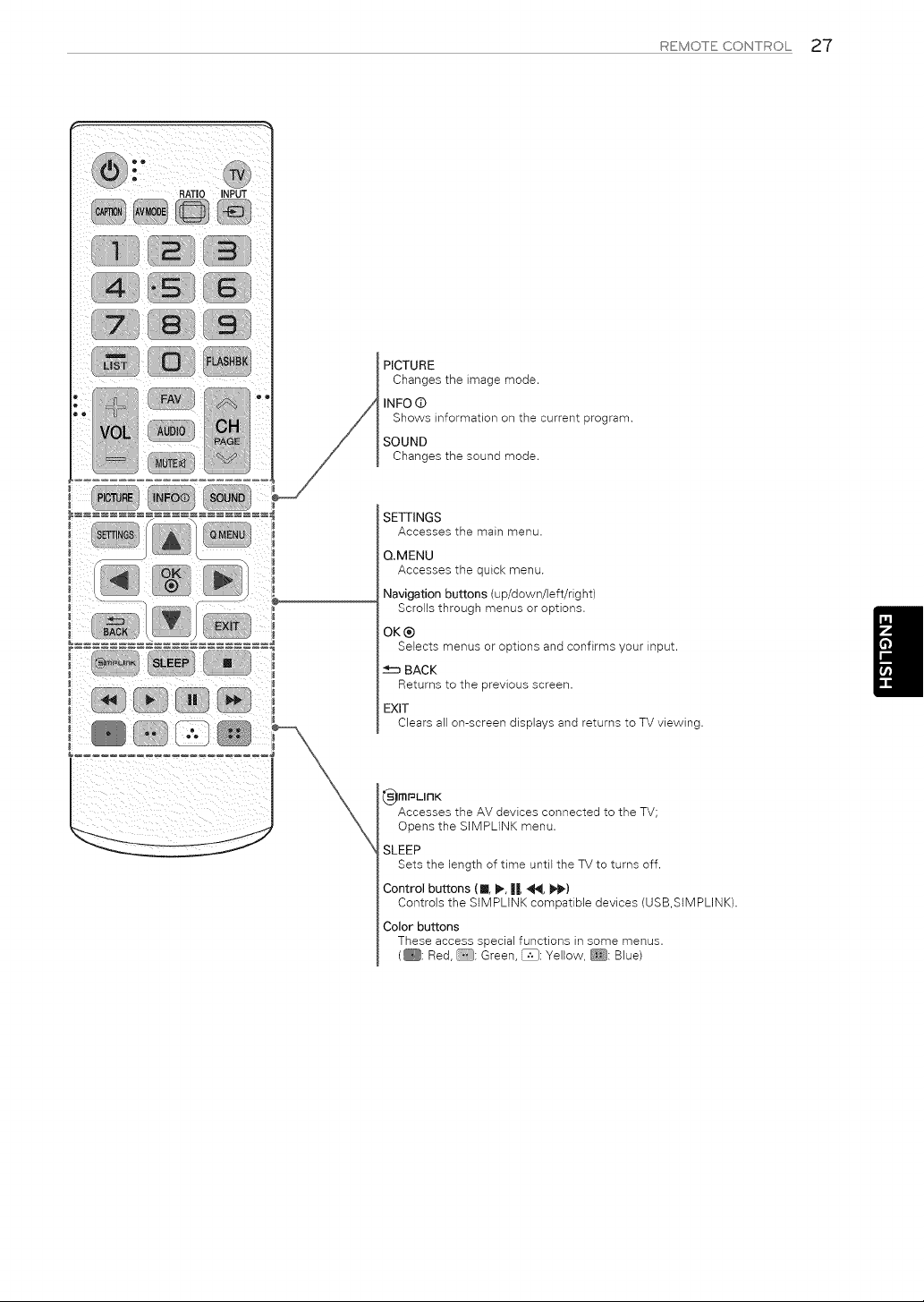
PICTURE
Changestheimagemode.
INFO(D
Showsinformationonthecurrentprogram.
SOUND
Changesthesoundmode.
..................
SETTINGS
Accesses the main menu.
QMENU
Accesses the quick menu.
Navigation buttons (up/down/left/right)
Scrolls through menus or options.
OK®
Selects menus or options and confirms your input.
BACK
Returns to the previous screen.
EXIT
Clears all on-screen displays and returns to TV viewing.
_imr_LlnK
Accesses the AV devices connected to the TV;
Opens the SIMPLINK menu.
SLEEP
Sets the lengthof time untilthe TV to turnsoff.
Control buttons (11, I1_,II, _, I1_,)
Controls the SIMPLINK compatible devices (USB,SIMPLINK).
Color buttons
These access special functions in some menus.
(_: Red, _: Green, _: Yellow, _: Blue)
28 WfiTCHNGTV
WATCHING TV
4 When the basic settings are complete,
press the OK button.
Turning the TV on for the first time
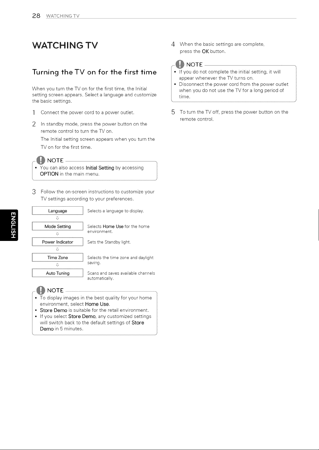
When you turn the TV on for the first time, the Initial
setting screen appears, Select a language and customize
the basic settings,
1 Connect the power cord to a power outlet,
2 In standby mode, press the power button on the
remote control to turn the TV on.
The Initial setting screen appears when you turn the
TV on for the first time,
5 To turn the TV off, press the power button on the
remote control.
Follow the on-screen instructions to customize your
TV settings according to your preferences.
Selects a languageto display.
Language
O
Mode Setting
O
Power Indicator
O
Time Zone
O
]
]
Selects Home Use for the home
environment.
Sets the Standby light.
Auto Tuning
]
]
Selects the time zone and daylight
saving.
Scans and saves available channels
automatically.
,@ NOTE
• To display images in the best quality for your home
environment, select Home Use.
• Store Demo is suitable for the retail environment.
• If you select Store Demo, any customized settings
will switch back to the default settings of Store
Demo in 5 minutes.
US NG THE USER GU DE 29
USING THE USER GUIDE
@
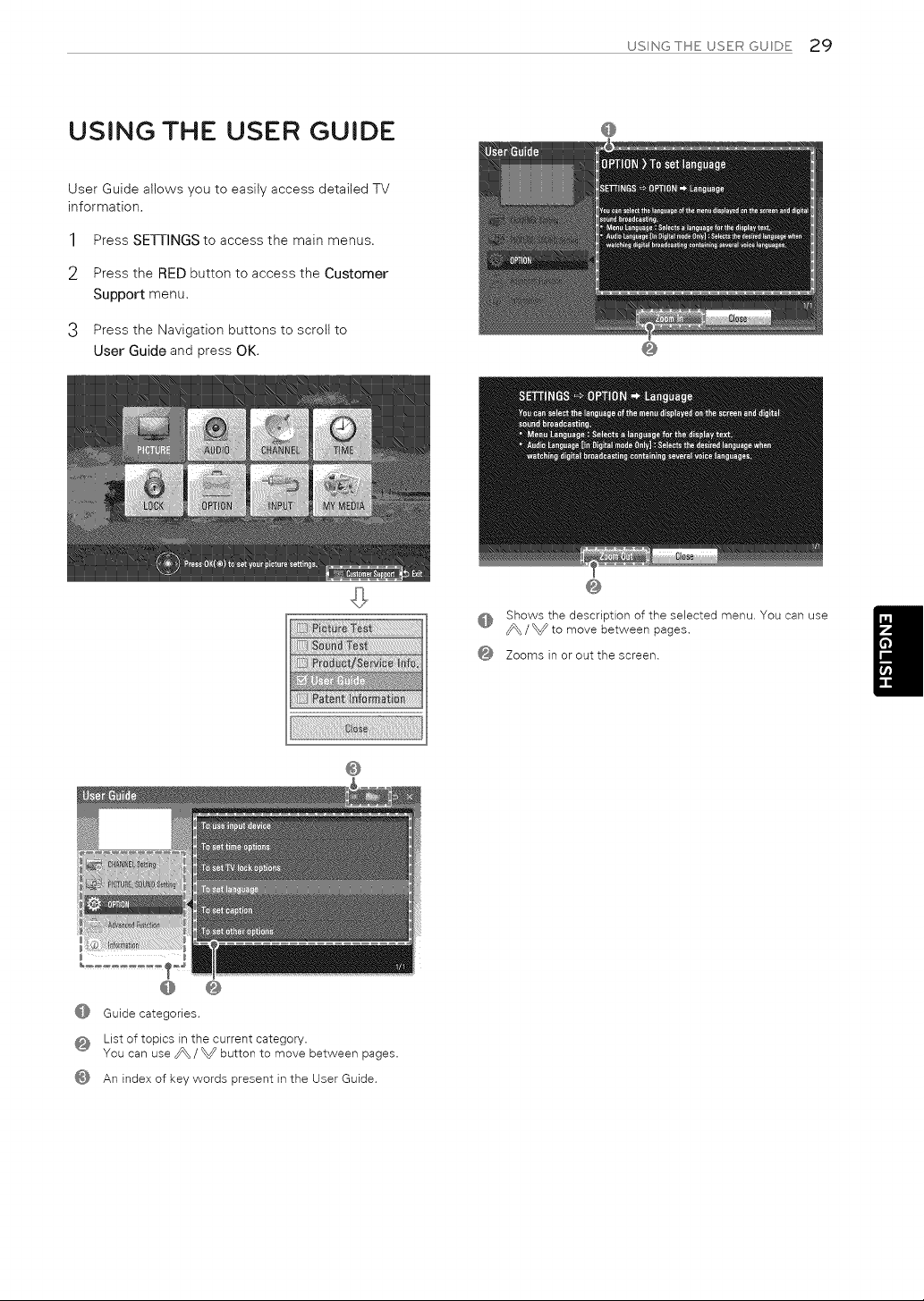
User Guide allows you to easily access detailed TV
information.
1 Press SETTINGS to access the main menus.
2 Press the RED button to access the Customer
Support menu.
3 Press the Navigation buttons to scroll to
User Guide and press OK.
@
@
@ Shows the description of the selected menu. You can use
_\ / _ to move between pages.
@ Zooms in or out the screen.
@
@ @
@ Guide categories.
@ List of topics in the current category.
You can use _ / _ button to move between pages.
@ An index of key words present in the User Guide.
30 SPECFCATONS
SPECIFICATIONS
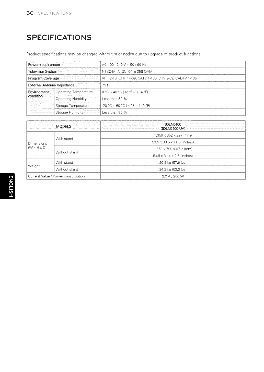
Product specifications may be changed without prior notice due to upgrade of product functions.
AC100-240V-50/60Hz
NTSC-M, ATSC, 64 & 256 QAM
Program Coverage VHF 2-13, UHF 14-69, CATV 1-135, DTV 2-69, CADTV 1-135
External Antenna Impedance 75 £2
60LN5400
MODELS H (60LN5400oUA)
1,359 x 852 x 297 (mm)
With stand
Dimensions 53.5 x 33.5 x 11.6 (inches)
(W x H x D) 1,359 x 799 x 67.2 (mm)
Without stand
53.5 x 31.4 x 2.6 (inches)
With stand 26.3 kg (57.9 Ibs)
Weight
Without stand 24.2 kg (53.3 Ibs)
Current Value / Power consumption 2.0 A / 200 W
SPECFCATONS 31
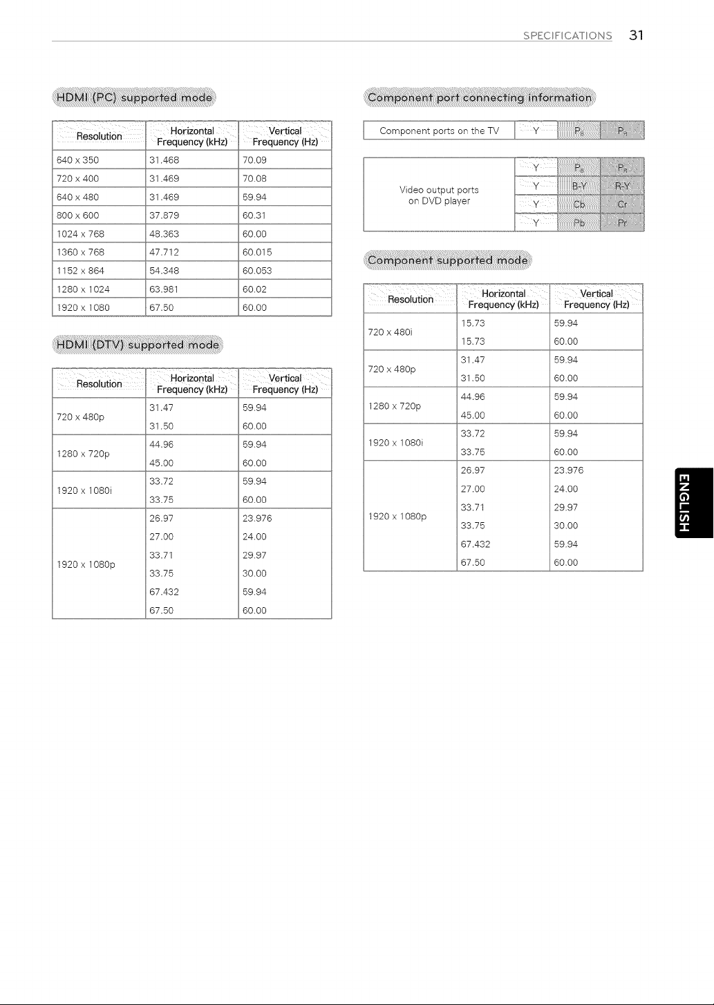
Resolution
640x350
720x400
640x480
800x600
1024x768
1360x768
1152x864
1280x1024
1920x1080
Horizontal
Frequency(kHZ)
31.466
31.469
31.469
37.879
46.363
47.712
54.346
63.961
67.50
vertical
Frequency(HZ)
i70.09
i70.08
59,94
60,31
i60,00
i60.015
i60.053
60.02
60.00
ResolutiOn Frequency (kHZ) Frequency (Hz)
31.47
720 x 480p
31.50
44.96
1280 x 720p
45.00
33.72
1920 x 1080i
33.75
26.97
27.00
33.71
1920 x 1080p
33.75
67.432
67.50
59.94
60.00
59.94
60.00
59.94
60.00
23.976
24.00
29.97
30,00
i59.94
i60.00
Video output ports
on DVD player
720 x 480p
1280 x 720p
1920 x 1080i
Resolution Frequency (kHZ)
15.73
720 x 480i
15.73
31.47
31.50
44.96
45.00
33.72
33.75
26.97
27.00
33.71
1920 x 1o80p
33.75
67.432
67.50
=_ ..................... _o=,.,=,
vertical
FreqUency (az)
59.94
60.00
59.94
60.00
59.94
60.00
59.94
60.00
23.976
24.00
29.97
30.00
59.94
60.00
32 MANTENANCE/TROUBLESHOOTNG
MAINTENANCE
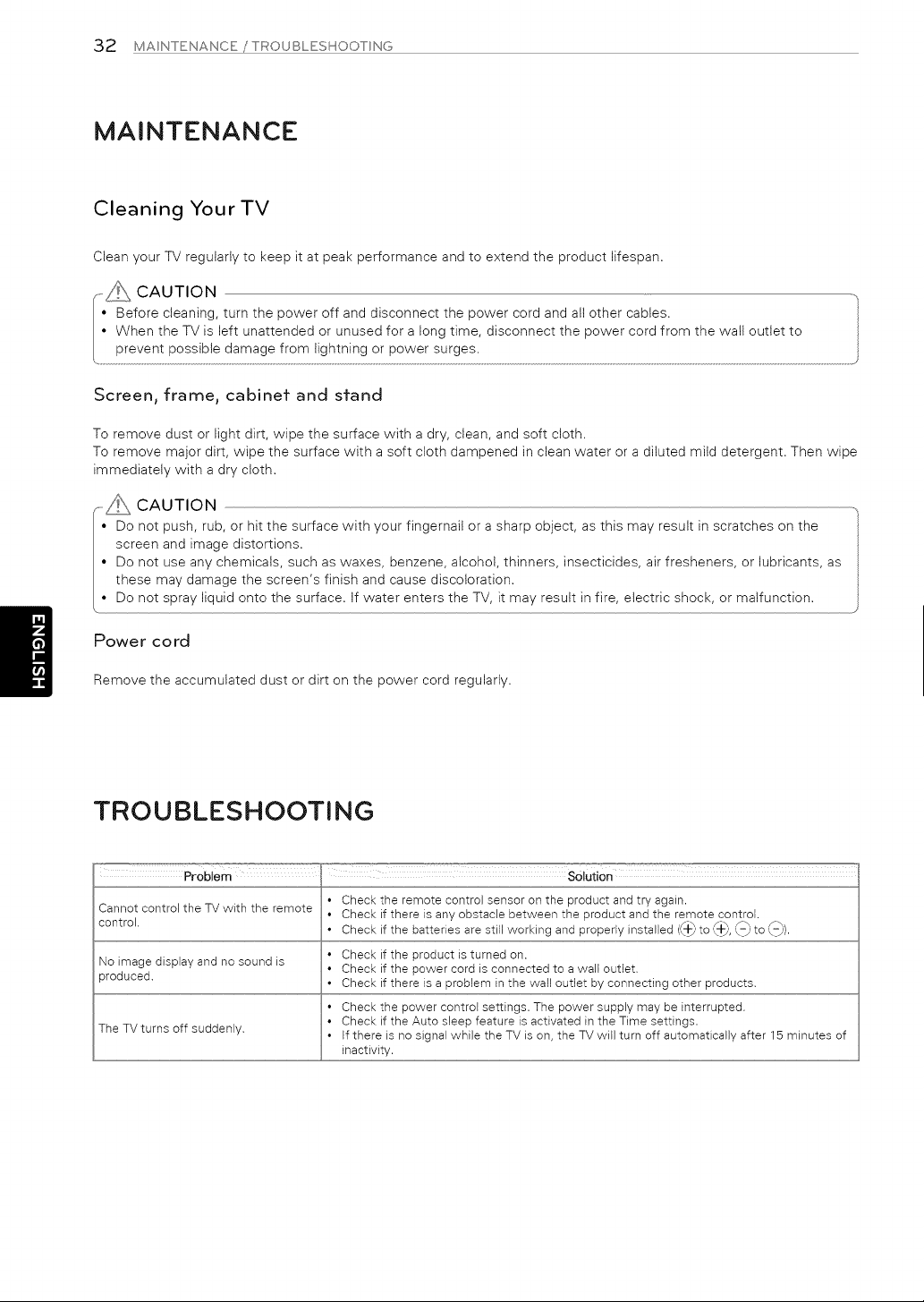
Cleaning Your TV
Clean your TV regularly to keep it at peak performance and to extend the product lifespan.
_\_ CAUTION -.
• Before cleaning, turn the power off and disconnect the power cord and all other cabtes.
• When the TV is left unattended or unused for a long time, disconnect the power cord from the walt outlet to
prevent possible damage from lightning or power surges
/ • j
Screen, frame, cabinet and stand
To remove dust or light dirt, wipe the surface with a dry, clean, and soft cloth.
To remove major dirt, wipe the surface with a soft cloth dampened in clean water or a diluted mild detergent. Then wipe
immediately with a dry cloth.
CAUTION
• Do not push, rub, or hitthe surface with your fingernailor a sharp object, as this may resultin scratches on the
screen and image distortions,
• Do not use any chemicals, such as waxes, benzene, alcohol,thinners, insecticides,airfresheners, or lubricants,as
these may damage the screen's finishand cause discoloration,
• Do not spray liquidonto the surface, ifwater enters the TV, itmay result in fire,electricshock, or malfunction,
Power cord
Remove the accumulated dust or dirt on the power cord regularly.
TROUBLESHOOTING
Problem ,, SOlution
• Check the remote control sensor on the product and try again.
Cannot control the TV with the remote
• Check if there is any obstacle between the product and the remote control.
control.
• Check if the batteries are still working and properly installed Cb to Cb, t_ to ,L_).
• Check if the product is turned on.
No image display and no sound is
• Check if the power cord is connected to a wall outlet.
oroduced.
• Check if there is a problem in the wall outlet by connecting other products.
• Check the power control settings. The power supply may be interrupted.
• Check if the Auto sleep feature is activated in the Time settings.
The TV turns off suddenly. • If there is no signal while the TV is on, the TV will turn off automatically after 15 minutes of
inactivity.
EXTEF¢NALCONTROLDEVCESETUP33
EXTERNAL CONTROL DEVICE SETUP
To obtain the external control device setup information, please visit www.lg.com.


Congratulations on your purchase! As you enjoy your new product,
please keep these safety tips in mind:
THE ISSUE
, The home theater entertainment experience is a growing trend and
larger flat panel displays are popular purchases. However, flat panel
displays are not always supported on the proper stands or installed
according to the manufacturer's recommendations.
, Flat panel displays that are inappropriately situated on dressers,
bookcases, shelves, desks, speakers, chests or carts may fall over
and cause injury.
°F[[i_ISMANUFACURER CARES!
* The consumer electronics industry is committed to making home
entertainment enjoyable and safe.
TUNE INTO SAFETY
One size does NOT fit all. Follow the manufacturer's
recommendations for the safe installation and use of your flat panel
display.
Carefully read and understand all enclosed instructions for proper
use of this product.
, Don't allow children to climb on or play with furniture and television
sets.
, Don't allow place flat panel displays on furniture that can easily be
used as steps, such as a chest of drawers.
, Remember that children can become excited while watching a
program, especially on a "larger than life" flat panel display.
Care should be taken to place or install the display where it cannot
be pushed, pulled over, or knocked down.
, Care should be taken to route all cords and cables connected to the
flat panel display so that they cannot be pulled or grabbed by curious
children.
WALL MOUNTING: IF YOU DECIDE TO WALL
MOUNT YOUR FLAT PANEL DISPLAY, ALWAYS:
, Use a mount that has been recommended by the display
manufacturer and/or listed by an independent laboratory
(such as UL, CSA, ETL).
, Follow all instructions supplied by the display and wall mount
manufacturers.
, If you have any doubts about your ability to safely install your flat
panel display, contact your retailer about professional installation.
, Make sure that the wall where you are mounting the display is
appropriate. Some wall mounts are not designed to be mounted to
walls with steel studs or old cinder block construction.
If you are unsure, contact a professional installer.
, A minimum of two people are required for installation.
Flat panel displays can be heavy.

Life's Good
For inquires or corrrrenls visilwwwlgcorr ol call;
1-800-243-0000 USA Corsurrer User
1-888-865-3026 U_A, Corr/rr ercial User
1-888-542-2623 CANADA
The model and serial numbers of the TV are
located on the back and one sde of the TV.
Record it below should you ever need service
MODEL
SERIAL
www.lg.com
This productqualifesfor ENERGY STAR ntle
facto y def:_ult (lo'r/e t,_se) ,,etti'/g
Cha'/g n( / t e facto y default setti'/gs or enabli°/g
o /e tea ]re,_ lay /crease powe consur/p on
that co(Id oxceeci tie I['nits necessary to quality
fo ENERGY STAR
Life's Good
,/
EXTERNAL
DEVICE S£
CONT
TUP
OL
Please read this manual carefully before operating the set and retain it for
future reference,
www.lg.corn
2 KEY CODES
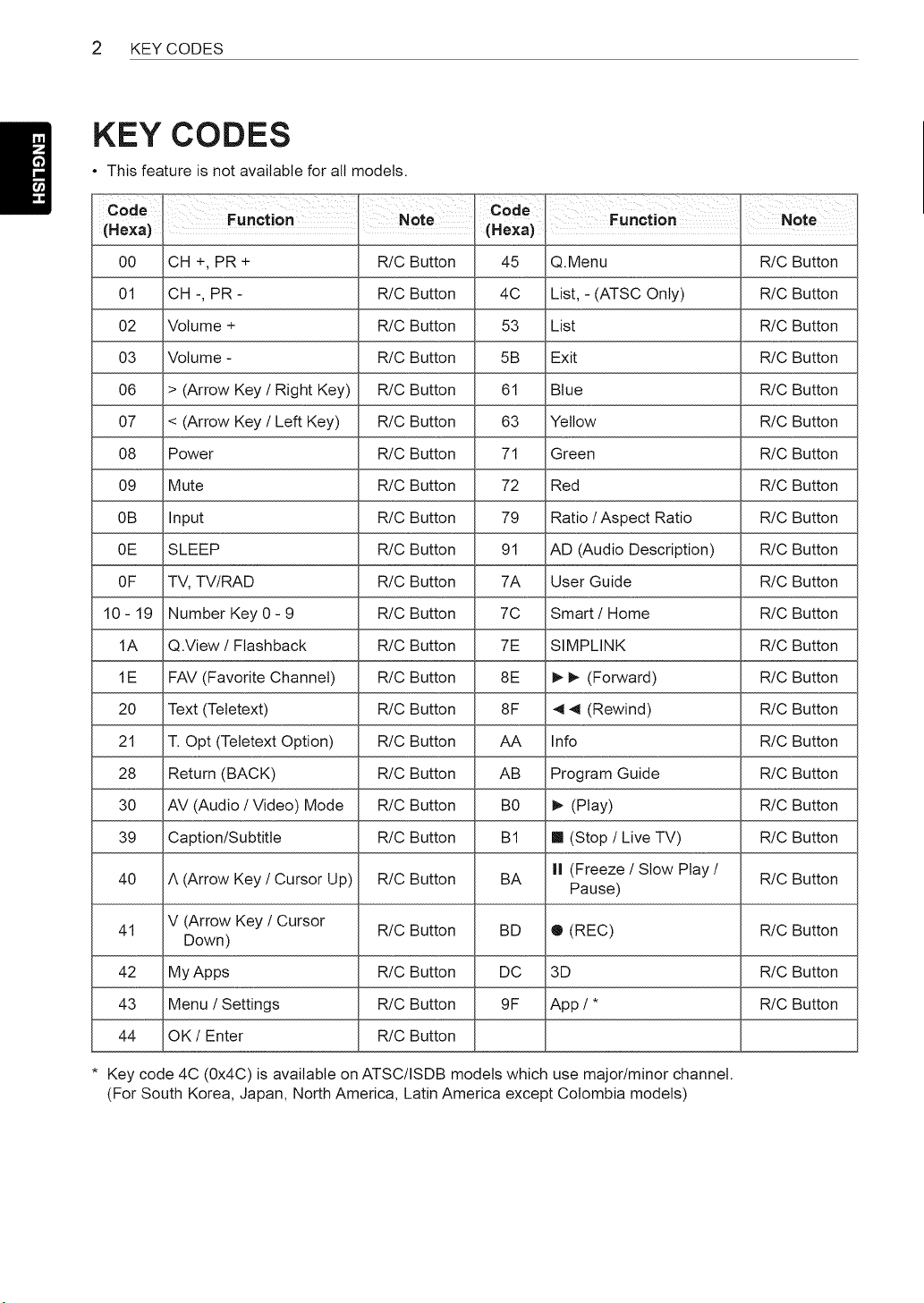
KEY CODES
• This feature is not available for all models.
Code
(Hexa)
00
01
O2
O3
O6
O7
O8
O9
0B
0E
OF
10-19
1A
IE
2O
21
28
3O
39
40
41
42
43
44
Function Note C°de
(He×a)
CH +, PR + R!C Button
CH -, PR - R/C Button
Volume + R!C Button
Volume - R/C Button
> (Arrow Key / Right Key) R/C Button
< (Arrow Key / Left Key) R/C Button
Power R!C Button
Mute R/C Button
Input R/C Button
SLEEP R/C Button
TV, TV/RAD R/C Button
Number Key 0 - 9 R/C Button
Q.View / Flashback R/C Button
FAV (Favorite Channel) R/C Button
Text (Tetetext) R/C Button
T. Opt (Tetetext Option) R/C Button
Return (BACK) R/C Button
AV (Audio / Video) Mode R/C Button
Caption/Subtitle R!C Button
A (Arrow Key / Cursor Up) R/C Button
V (Arrow Key / Cursor
R/C Button
Down)
My Apps R/C Button
Menu / Settings R!C Button
OK/Enter R/C Button
45
4C
53
5B
61
63
71
72
79
91
7A
7C
7E
8E
8F
AA
AB
B0
BI
BA
BD
DC
9F
Function Note
Q.Menu R!C Button
List, - (ATSC Only) R/C Button
List R!C Button
Exit R/C Button
Blue R!C Button
Yellow R/C Button
Green R!C Button
Red R/C Button
Ratio / Aspect Ratio R/C Button
AD (Audio Description) R/C Button
User Guide R!C Button
Smart / Home R/C Button
SIMPLINK R/C Button
_ (Forward) R/C Button
4 4 (Rewind) R!C Button
Info R!C Button
Program Guide R!C Button
I_ (Play) R/C Button
!11(Stop / Live TV) R/C Button
II (Freeze / Slow Play / R/C Button
Pause)
® (REC) R/C Button
3D R!C Button
App / * R/C Button
* Key code 4C (0x4C) is available on ATSC/ISDB models which use major/minor channel.
(For South Korea, Japan, North America, Latin America except Colombia models)
EXTERNALCONTROLDEVICESETUP3
EXTERNAL CONTROL DEVICE SETUP
• Image shown may differ from your TV.
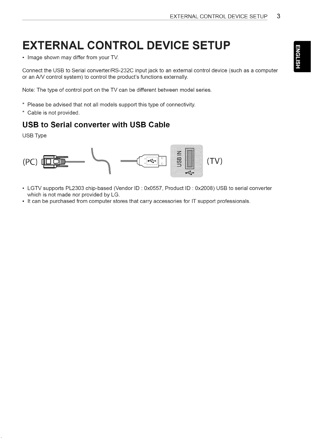
Connect the USB to Serial converter/RS-232C input jack to an external control device (such as a computer
or an A/V control system) to control the product's functions externally.
Note: The type of control port on the TV can be different between model series.
* Please be advised that not all models support this type of connectivity.
* Cable is not provided.
USB to Serial converter with USB Cable
USB Type
(PC)
(TV)
• LGTV supports PL2303 chip-based (Vendor ID " 0x0557, Product ID " 0x2008) USB to serial converter
which is not made nor provided by LG.
• It can be purchased from computer stores that carry accessories for IT support professionals.
4 EXTERNAL CONTROL DEVICE SETUP
RS-232C with RS-232C Cable (Legacy)
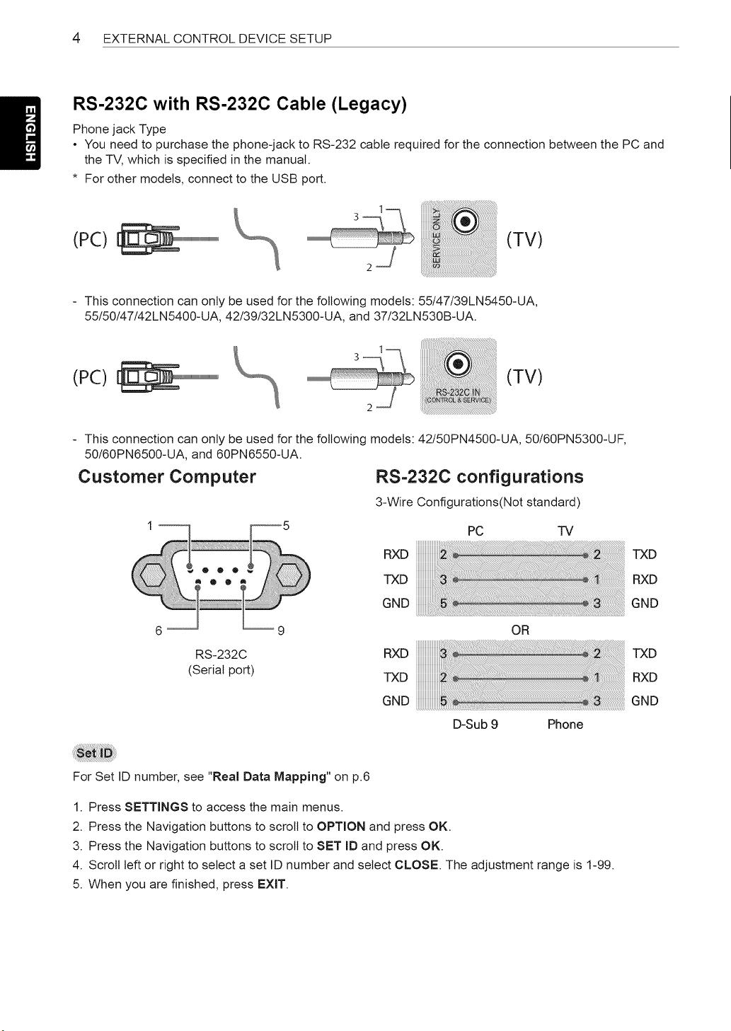
Phone jack Type
• You need to purchase the phone-jack to RS-232 cable required for the connection between the PC and
the TV, which is specified in the manual.
* For other models, connect to the USB port.
(PC)
(TV)
This connection can only be used for the following models: 55/47/39LN5450-UA,
55/50/47/42LN5400-UA, 42/39/32LN5300-UA, and 37/32LN530B-UA.
(PC) (TV)
This connection can only be used for the following models: 42/50PN4500-UA, 50/60PN5300-UF,
50/60PN6500-UA, and 60PN6550-UA.
Customer Computer RS=232C configurations
6 -- --9
RS-232C
(Serial port)
3-Wire Configurations(Not standard)
PC TV
RXD iiiiiiiiiiiiiiiiiiiiii!!_iiiiiii!i!!i!i!i!i i!!iii_i!i_!!_!_!_!!_i_!_!i_!_!_!_!_!_!_!_!_!_!_!_!_!_!_!i_!i!_!_iiTXD
TXD iiiiiiiiiiiiiiii_!_!_!_!ilililiiii!!i!!i!!i!!i!!i!i __!__!__!__!__!_!!ii!!i!_i!_i!_i!ii!ii!ii!ii!ii!ii!ii!ii!ii!ii!ii!ii!ii!ii!i_!i_!i_!i!_______iRXD
GND iiiiiiiiiiii_!_!_!j_!i_!!_!!_!!j!iiii!i!!i!!iiiiiiiiiiiiiil!i!!i!!_!!i!_i!__!__!__!__!__!__!__!__!__!__!__!__!__!__!__!i_!_!__!__!i__i__i__iiiiGND
OR
RXD iiiiiiiiiiiiiiiiiiiiiii_!iiiii!i!i!iiiiiii !_!_!_!i_!___i_ii_i_ii_ii_i!_i!_i!_!__!__!_i___!_i!_!!!i!_i!_i!_!_!i!_i__i!_i_i___TXD
TXD iiiiiiiiiiiiiiiiiiiiiii_iiiiiiii!!!ii!!!i !!!i!i!i!_!_!_!_!!_i!i!!i!_i!!i!_i!_i!_i!_i!_i!_i!_i!_i!_i!_!_!i_!_i!_i_ii_i!i_i!i_RXD
GND iiiiiiiiiiiiiiiiiiiiiiii_iiiiiiiiiiiiilil _ii_i_i!i!!i_i!i_!i_!i_!i_!i_!i_!i_!i_!i_!i_!i_!i_!i_!i_!i_!i_!i_!i_!i_!i_!i_!i_!i_iGND
D-Sub 9 Phone
For Set ID number, see "Real Data Mapping" on p.6
1. Press SETTINGS to access the main menus.
2. Press the Navigation buttons to scroll to OPTION and press OK.
3. Press the Navigation buttons to scroll to SET ID and press OK.
4. Scroll left or right to select a set ID number and select CLOSE. The adjustment range is 1-99.
5. When you are finished, press EXIT.
EXTERNALCONTROLDEVICESETUP 5
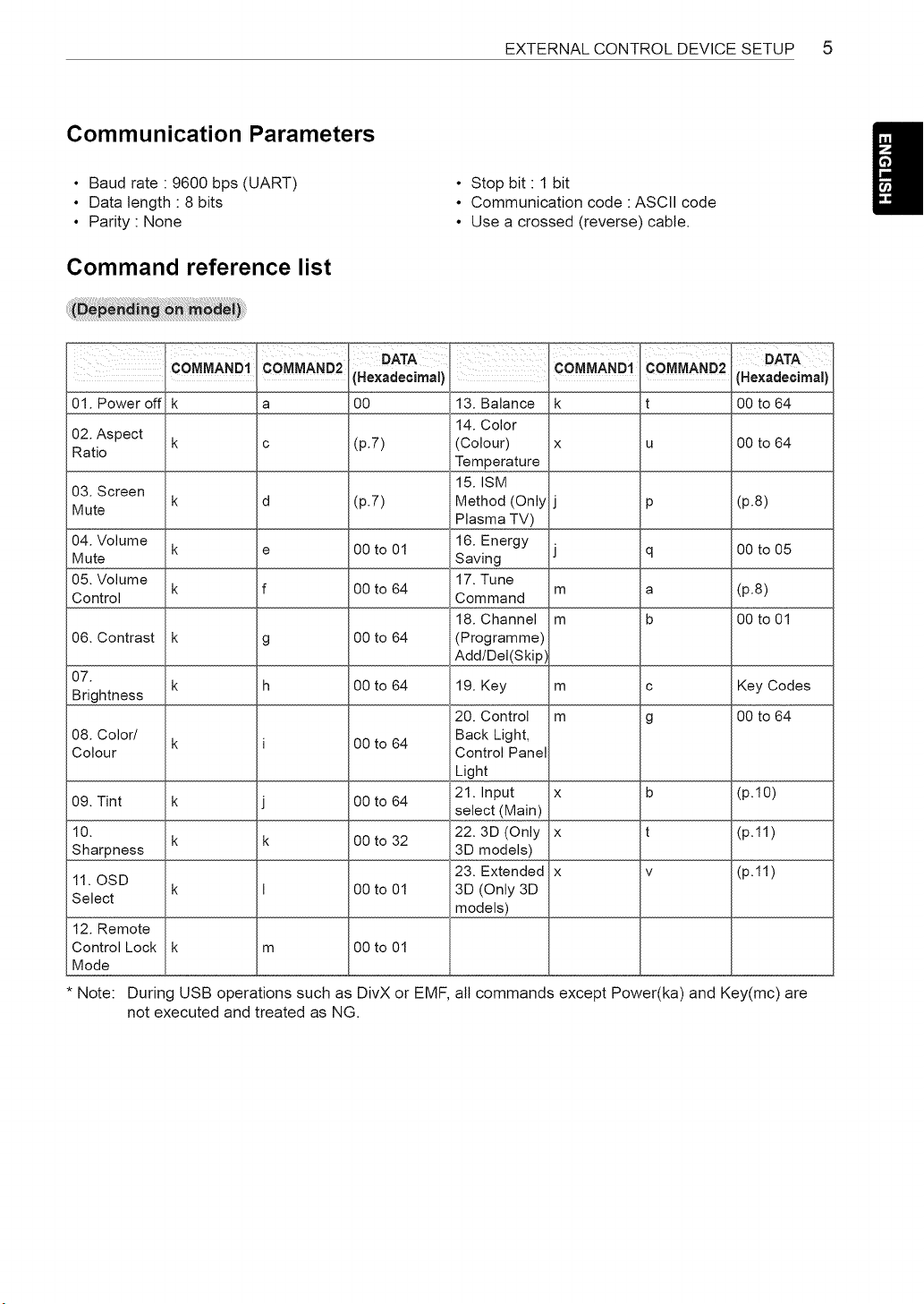
Communication Parameters
• Baud rate " 9600 bps (UART)
• Data length " 8 bits
• Parity None
Command reference list
• Stop bit 1 bit
• Communication code : ASCII code
• Use a crossed (reverse) cable.
COMMA.D1OMMAND2
01. Power off k a
02. Aspect k c
Ratio
Hexadecima,)
00
,COMMA"O!,COM A"02O=A
(Hexadecimal)
13. Balance k t 00 to 64
14. Color
(p.7) (Colour) x u 00 to 64
Temperature
03. Screen 15. ISM
Mute k d (p.7) Method (Only p (p.8)
Plasma TV)
04. Volume k e 00 to 01 16. Energy
Mute Saving q 00 to 05
05. Volume 17. Tune
Control k f 00 to 64 Command m a (p.8)
18. Channel m b 00to01
06. Contrast k g 00 to 64 (Programme)
Add/Del(Skip)
07.
k h 00 to 64 19. Key m c Key Codes
Brightness
20. Control m g 00 to 64
08. Color/ k 00 to 64 Back Light,
Colour Control Panel
Light
21. Input x b (p.10)
09. Tint k 00 to 64
select (Main)
10. k k 00to32 22.3D(Only x t (p.11)
Sharpness 3D models) _
11. OSD 23. Extended x v (p.11)
Select k 00 to 01 3D (Only 3D
models)
12. Remote
Control Lock
Mode
00 to 01
i/
m
Note: During USB operations such as DivX or EMF, all commands except Power(ka) and Key(mc) are
not executed and treated as NG.
6 EXTERNALCONTROLDEVICESETUP
Transmission / Receiving Protocol
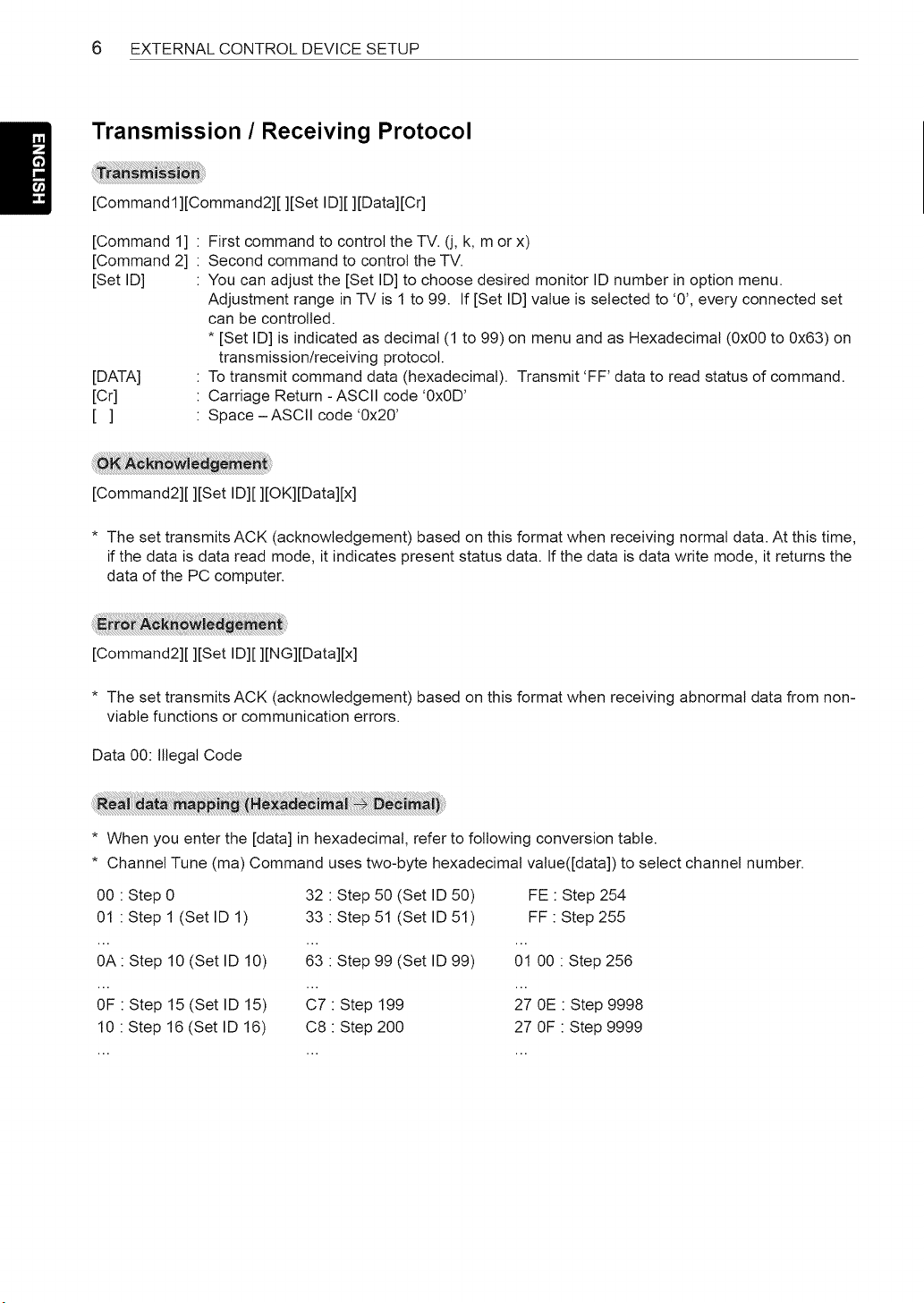
[Commandl][Command2][ ][Set ID][ ][Data][Cr]
[Command 1]
[Command 2]
[Set ID]
[DATA]
[Cr]
[]
First command to control the TV. (j, k, m or x)
Second command to control the TV.
You can adjust the [Set ID] to choose desired monitor ID number in option menu.
Adjustment range in TV is 1 to 99. If [Set ID] value is selected to '0', every connected set
can be controlled.
* [Set ID] is indicated as decimal (1 to 99) on menu and as Hexadecimal (0x00 to 0x63) on
transmission/receiving protocol.
To transmit command data (hexadecimal). Transmit 'FF' data to read status of command.
Carriage Return - ASCII code '0x0D'
Space - ASCII code '0x20'
[Command2][ ][Set ID][ ][OK][Data][x]
* The set transmits ACK (acknowledgement) based on this format when receiving normal data. At this time,
if the data is data read mode, it indicates present status data. If the data is data write mode, it returns the
data of the PC computer.
[Command2][ ][Set ID][ ][NG][Data][x]
* The set transmits ACK (acknowledgement) based on this format when receiving abnormal data from non-
viable functions or communication errors.
Data 00: Illegal Code
* When you enter the [data] in hexadecimal, refer to following conversion table.
* Channel Tune (ma) Command uses two-byte hexadecimal value([data]) to select channel number.
00 : Step 0 32 : Step 50 (Set ID 50) FE : Step 254
01 : Step 1 (Set ID 1) 33 : Step 51 (Set ID 51) FF : Step 255
0A: Step 10 (Set ID 10) 63 : Step 99 (Set ID 99) 01 00 : Step 256
OF : Step 15 (Set ID 15) C7 : Step 199 27 0E : Step 9998
10 : Step 16 (Set ID 16) C8 : Step 200 27 OF : Step 9999
EXTERNALCONTROLDEVICESETUP 7
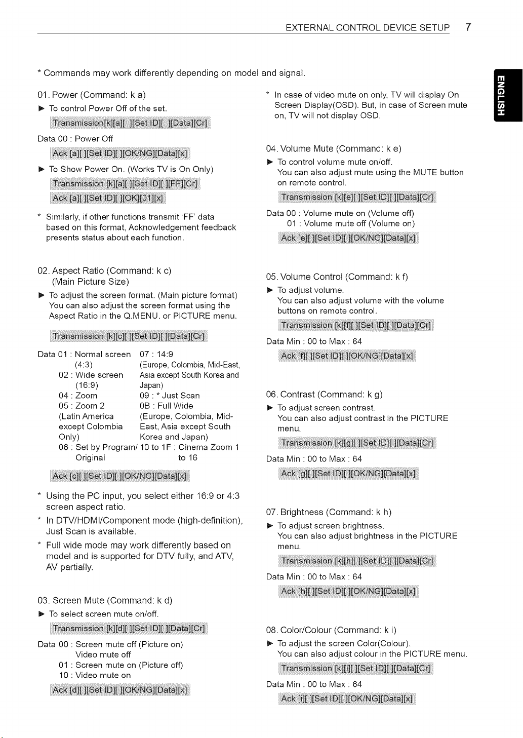
* Commands may work differently depending on model and signal.
01. Power (Command: k a)
I_ To control Power Off of the set.
* In case of video mute on only, TV will display On
Screen Display(OSD). But, in case of Screen mute
on, TV will not display OSD.
Data 00 : Power Off
I_ To Show Power On. (Works TV is On Only)
04. Volume Mute (Command: k e)
I_ To control volume mute on/off.
You can also adjust mute using the MUTE button
on remote control.
* Similarly, if other functions transmit 'FF' data
based on this format, Acknowledgement feedback
presents status about each function.
Data O0 : Volume mute on (Volume off)
01 : Volume mute off (Volume on)
i
02. Aspect Ratio (Command: k c)
(Main Picture Size)
I_ To adjust the screen format. (Main picture format)
You can also adjust the screen format using the
Aspect Ratio in the Q.MENU. or PICTURE menu.
05. Volume Control (Command: k f)
I_ To adjust volume.
You can also adjust volume with the volume
buttons on remote control.
Data 01 : Normal screen
(4:3)
02 : Wide screen
(16:9)
04 : Zoom
05 : Zoom 2
(Latin America
except Colombia
Only)
07 : 14:9
(Europe, Colombia, Mid-East,
Asia except South Korea and
Japan)
09 : * Just Scan
0B : Full Wide
(Europe, Colombia, Mid-
East, Asia except South
Korea and Japan)
06 : Set by Program/10 to IF : Cinema Zoom 1
Original to 16
* Using the PC input, you select either 16:9 or 4:3
screen aspect ratio.
* In DTV/HDMI/Component mode (high-definition),
Just Scan is available.
* Full wide mode may work differently based on
model and is supported for DTV fully, and AT',/,
AV partially.
03. Screen Mute (Command: k d)
I_ To select screen mute on/off.
Data O0 : Screen mute off (Picture on)
Video mute off
01 : Screen mute on (Picture off)
10 : Video mute on
Data Min : 00 to Max : 64
06. Contrast (Command: k g)
I_ To adjust screen contrast.
You can also adjust contrast in the PICTURE
menu.
Data Min : 00 to Max : 64
07. Brightness (Command: k h)
I_ To adjust screen brightness.
You can also adjust brightness in the PICTURE
menu.
Data Min : 00 to Max : 64
08. Color/Colour (Command: k i)
I_ To adjust the screen Color(Colour).
You can also adjust colour in the PICTURE menu.
Data Min : 00 to Max : 64
8 EXTERNAL CONTROL DEVICE SETUP
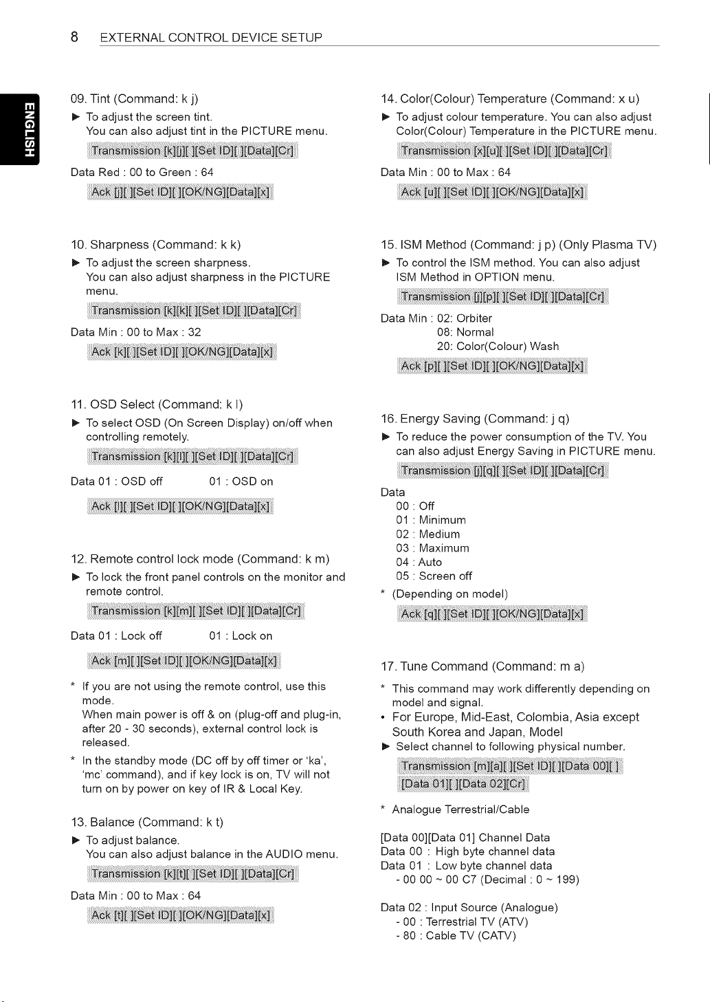
09. Tint (Command: k j)
_- To adjust the screen tint.
You can also adjust tint in the PICTURE menu.
14. Color(Colour) Temperature (Command: x u)
_- To adjust colour temperature. You can also adjust
Color(Colour) Temperature in the PICTURE menu.
Data Red • 00 to Green • 64 Data Min • 00 to Max • 64
10. Sharpness (Command: k k)
_- To adjust the screen sharpness.
You can also adjust sharpness in the PICTURE
menu.
Data Min • 00 to Max • 32
11. OSD Select (Command: k t)
_- To select OSD (On Screen Display) on/off when
controlling remotely.
Data 01 : OSD off 01 : OSD on
12. Remote control lock mode (Command: k m)
_- To lock the front panel controls on the monitor and
remote control.
Data 01 " Lock off 01 " Lock on
* If you are not using the remote control, use this
mode.
When main power is off & on (plug-off and plug-in,
after 20 - 30 seconds), external control lock is
released.
* In the standby mode (DC off by off timer or 'ka',
'mc' command), and if key lock is on, TV will not
turn on by power on key of IR & Local Key.
13. Balance (Command: k t)
_- To adjust balance.
You can also adjust balance in the AUDIO menu.
Data Min " 00 to Max " 64
15. ISM Method (Command: j p) (Only Plasma TV)
_- To control the ISM method. You can also adjust
ISM Method in OPTION menu.
Data Min • 02: Orbiter
08: Normal
20: Color(Colour) Wash
16. Energy Saving (Command: j q)
_- To reduce the power consumption of the TV. You
can also adjust Energy Saving in PICTURE menu.
Data
00 : Off
01 : Minimum
02 : Medium
03 : Maximum
04 : Auto
05 : Screen off
* (Depending on model)
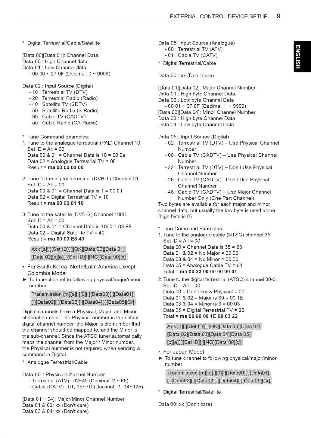
17. Tune Command (Command: m a)
* This command may work differently depending on
model and signal.
• For Europe, Mid-East, Colombia, Asia except
South Korea and Japan, Model
_- Select channel to following physical number.
* Analogue Terrestrial/Cable
[Data 00][Data 01] Channel Data
Data 00 : High byte channel data
Data 01 : Low byte channel data
- 00 00 ~ 00 C7 (Decimal: 0 ~ 199)
Data 02 • Input Source (Analogue)
- 00 • Terrestrial TV (ATV)
- 80 • Cable TV (CATV)
EXTERNALCONTROLDEVICESETUP 9
* Digital Terrestrial/Cable/Satellite
[Data 00][Data 01]: Channel Data
Data 00 : High Channel data
Data 01 : Low Channel data
- 00 00 ~ 27 OF (Decimal: 0 ~ 9999)
Data 02 : Input Source (Digital)
- 10 : Terrestrial TV (DTV)
- 20 : Terrestrial Radio (Radio)
- 40 : Satellite TV (SDTV)
- 50 : Satellite Radio (S-Radio)
- 90 : Cable TV (CADTV)
- a0 : Cable Radio (CA-Radio)
* Tune Command Examples:
1. Tune to the analogue terrestrial (PAL) Channel 10.
Set ID = All = 00
Data 00 & 01 = Channel Data is 10 = 00 0a
Data 02 = Analogue Terrestrial TV = 00
Result = ma 90 90 9a 90
2. Tune to the digital terrestrial (DVB-T) Channel 01.
Set ID = All = 00
Data 00 & 01 = Channel Data is 1 = 00 01
Data 02 = Digital Terrestrial TV = 10
Result = ma 90 90 91 19
3. Tune to the satellite (DVB-S) Channel 1000.
Set ID = All = 00
Data 00 & 01 = Channel Data is 1000 = 03 E8
Data 02 = Digital Satellite TV = 40
Result = ma 00 03 E8 40
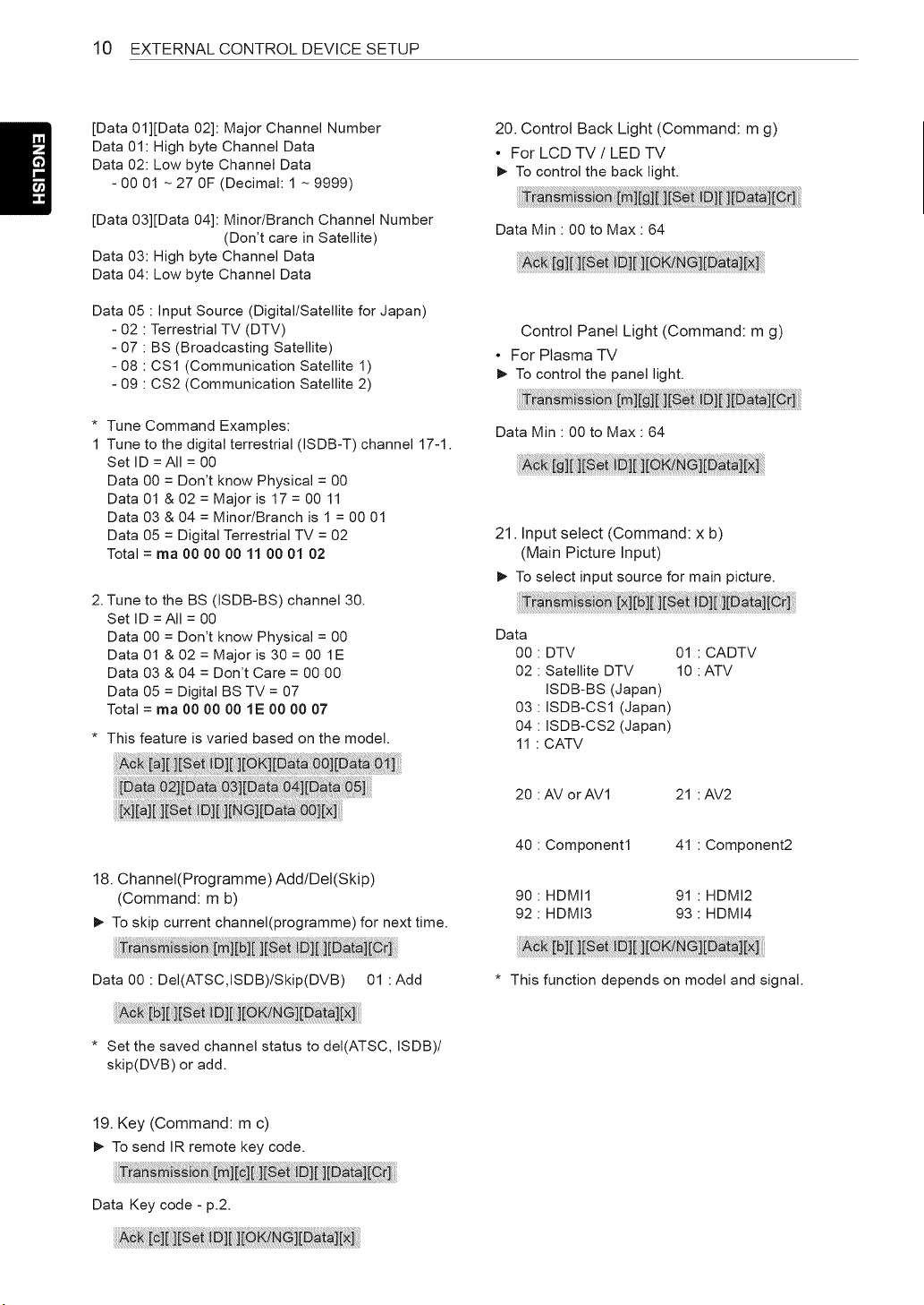
• For South Korea, North/Latin America except
Colombia Model
_- To tune channel to following physical/major/minor
number.
Digital channels have a Physical, Major, and Minor
channel number. The Physical number is the actual
digital channel number, the Major is the number that
the channel should be mapped to, and the Minor is
the sub-channel. Since the ATSC tuner automatically
maps the channel from the Major / Minor number,
the Physical number is not required when sending a
command in Digital.
* Analogue Terrestrial/Cable
Data 00 : Physical Channel Number
- Terrestrial (ATV) : 02~45 (Decimal: 2 ~ 69)
- Cable (CATV) : 01, 0E~7D (Decimal: 1, 14~125)
[Data 01 ~ 04]: Major/Minor Channel Number
Data 01 & 02: xx (Don't care)
Data 03 & 04: xx (Don't care)
Data 05: Input Source (Analogue)
- 00 : Terrestrial TV (ATV)
- 01 : Cable TV (CATV)
* Digital Terrestrial/Cable
Data 00 : xx (Don't care)
[Data 01][Data 02]: Major Channel Number
Data 01 : High byte Channel Data
Data 02 : Low byte Channel Data
- 00 01 ~ 27 OF (Decimal: 1 ~ 9999)
[Data 03][Data 04]: Minor Channel Number
Data 03 : High byte Channel Data
Data 04 : Low byte Channel Data
Data 05 : Input Source (Digital)
- 02 : Terrestrial TV (DTV) - Use Physical Channel
Number
- 06 : Cable TV (CADTV) - Use Physical Channel
Number
- 22 : Terrestrial TV (DTV) - Don't Use Physical
Channel Number
- 26 : Cable TV (CADTV) - Don't Use Physical
Channel Number
- 46 : Cable TV (CADTV) - Use Major Channel
Number Only (One Part Channel)
Two bytes are available for each major and minor
channel data, but usually the low byte is used alone
(high byte is 0).
* Tune Command Examples:
1. Tune to the analogue cable (NTSC) channel 35.
Set ID = All = 00
Data 00 = Channel Data is 35 = 23
Data 01 & 02 = No Major = 00 00
Data 03 & 04 = No Minor = 00 00
Data 05 = Analogue Cable TV = 01
Total = ma 90 23 00 90 90 00 01
2. Tune to the digital terrestrial (ATSC) channel 30-3.
Set ID = All = 00
Data 00 = Don't know Physical = 00
Data 01 & 02 = Major is 30 = 00 1E
Data 03 & 04 = Minor is 3 = 00 03
Data 05 = Digital Terrestrial TV = 22
Total = ma 00 00 00 1E 00 03 22
• For Japan Model
_- To tune channel to following physical/major/minor
number.
* Digital Terrestrial/Satellite
Data 00: xx (Don't care)
10 EXTERNAL CONTROL DEVICE SETUP
[Data Ol][Data 02]: Major Channel Number
Data 01: High byte Channel Data
Data 02: Low byte Channel Data
- 00 01 ~ 27 OF (Decimal: 1 ~ 9999)
[Data 03][Data 04]: Minor/Branch Channel Number
(Don't care in Satellite)
Data 03: High byte Channel Data
Data 04: Low byte Channel Data
Data 05 : Input Source (Digital/Satellite for Japan)
- 02 : Terrestrial TV (DTV)
- 07 : BS (Broadcasting Satellite)
- 08 : CS1 (Communication Satellite 1)
- 09 : CS2 (Communication Satellite 2)
* Tune Command Examples:
1 Tune to the digital terrestrial (ISDB-T) channel 17-1.
Set ID = All = 00
Data 00 = Don't know Physical = 00
Data 01 & 02 = Major is 17 = 00 11
Data 03 & 04 = Minor/Branch is 1 = 00 01
Data 05 = Digital Terrestrial TV = 02
Total = ma 90 90 90 11 90 91 92
2. Tune to the BS (ISDB-BS) channel 30.
Set ID = All = 00
Data 00 = Don't know Physical = 00
Data 01 & 02 = Major is 30 = 00 1E
Data 03 & 04 = Don't Care = 00 00
Data 05 = Digital BS TV = 07
Total = ma 90 90 90 1E 90 90 07
* This feature is varied based on the model.
20. Control Back Light (Command: m g)
• For LCD TV / LED TV
_- To control the back light.
Data Min : 00 to Max : 64
Control Panel Light (Command: m g)
• For Plasma TV
_- To control the panel light.
Data Min : 00 to Max : 64
21. Input select (Command: x b)
(Main Picture Input)
_- To select input source for main picture.
Data
00
O2
O3
O4
11
DTV
Satellite DTV
ISDB-BS (Japan)
ISDB-CS1 (Japan)
ISDB-CS2 (Japan)
CATV
01 : CADTV
10 : ATV
20 AV orAV1 21 :AV2
18. Channel(Programme) Add/Del(Skip)
(Command: m b)
_- To skip current channel(programme) for next time.
4O
90
92
Component1 41
HDMI1 91
HDMI3 93
Component2
HDMI2
HDMI4
Data 00 : DeI(ATSC,ISDB)/Skip(DVB) 01 : Add * This function depends on model and signal.
* Set the saved channel status to deI(ATSC, ISDB)/
skip(DVB) or add.
19. Key (Command: m c)
_- To send IR remote key code.
Data Key code - p.2.
EXTERNAL CONTROL DEVICE SETUP 11
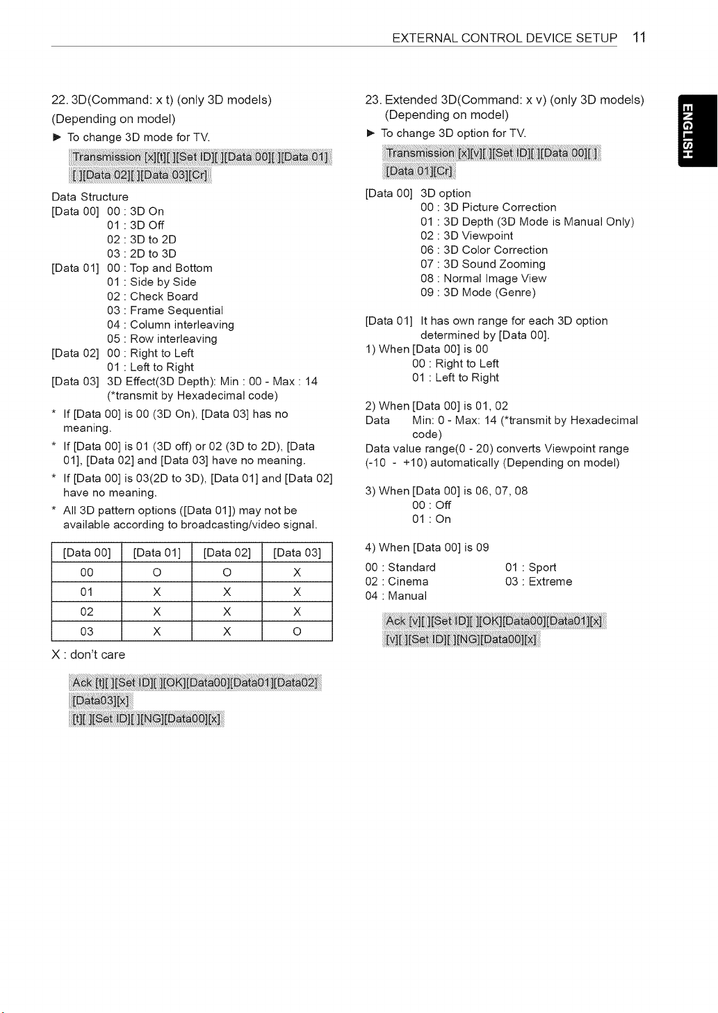
22.3D(Command: x t) (only 3D models)
(Depending on model)
_- To change 3D mode for TV.
23. Extended 3D(Command: x v) (only 3D models)
(Depending on model)
_- To change 3D option for TV.
Data Structure
[Data00] 00:3DOn
01 : 3D Off
02 : 3D to 2D
03 : 2D to 3D
[Data 01] 00 : Top and Bottom
01 : Side by Side
02 : Check Board
03 : Frame Sequential
04 : Column interleaving
05 : Row interleaving
[Data 02] 00 : Right to Left
01 : Left to Right
[Data 03] 3D Effect(3D Depth): Min : 00 - Max : 14
(*transmit by Hexadecimal code)
* If [Data 00] is 00 (3D On), [Data 03] has no
meaning.
* If [Data 00] is 01 (3D off) or 02 (3D to 2D), [Data
01], [Data 02] and [Data 03] have no meaning.
* If [Data 00] is 03(2D to 3D), [Data 01] and [Data 02]
have no meaning.
* All 3D pattern options ([Data 01]) may not be
available according to broadcasting/video signal.
[Data 00] [Data 01] [Data 02] [Data 03]
00 O O X
01 X X X
02 X X X
03 X X O
X : don't care
[Data 00] 3D option
00 : 3D Picture Correction
01 : 3D Depth (3D Mode is Manual Only)
02 : 3D Viewpoint
06 : 3D Color Correction
07 : 3D Sound Zooming
08 : Normal Image View
09 : 3D Mode (Genre)
[Data 01] It has own range for each 3D option
determined by [Data 00].
1) When [Data 00] is 00
00 : Right to Left
01 : Left to Right
2) When [Data 00] is 01,02
Data Min: 0 - Max: 14 (*transmit by Hexadecimal
code)
Data value range(0 - 20) converts Viewpoint range
(-10 - +10) automatically (Depending on model)
3) When [Data 00] is 06, 07, 08
00 : Off
01 : On
4) When [Data 00] is 09
00 : Standard 01 : Sport
02 : Cinema 03 : Extreme
04 : Manual
Life's Good