1
Unmanaged Industrial
Gigabit Ethernet Switches,
Plug and Play, Mountable
Models: NGI-U05, NGI-U16
1111 W. 35th Street, Chicago, IL 60609 USA • tripplite.com/support
Copyright © 2022 Tripp Lite. All rights reserved.
Owner’s Manual
WARRANTY REGISTRATION
Register your product today and be automatically entered to win an ISOBAR
®
surge protector in our monthly drawing!
tripplite.com/warranty
Español 17 • Français 33 • Русский 49 • Deutsch 65

2
• NGI-U05 or NGI-U16 Gigabit Ethernet Switch
• Owner’s Manual
Package Contents
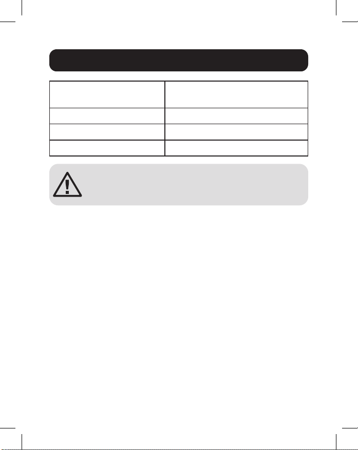
Product Features
• 5 (NGI-U05) or 16 (NGI-U16) auto-negotiable 10/100/1000
Mbps RJ45 ports
• Supports auto MDI/MDI-X crossover function
• Supports operating temperature range of -40°C to 75°C
(-40°F to 167°F)
• Easy-to-read LEDs indicate connection and activity status
for each port
• Meets the following IEEE standards:
• IEEE 802.3 10Base-T
• IEEE 802.3u 100Base-T
• IEEE 802.3ab 1000Base-T
• IEEE 802.3 Auto Negotiation
• IEEE 802.3x Flow Control
• Supports MAC address auto-learning and auto-aging
• Preinstalled durable rail clip mounts rmly to any standard
35 mm DIN rail*
• Simple plug-and-play installation and operation with no
conguration required
*Note: Only NGI-U05 is both DIN and wall mountable

3
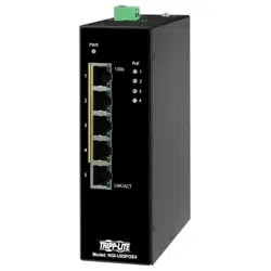
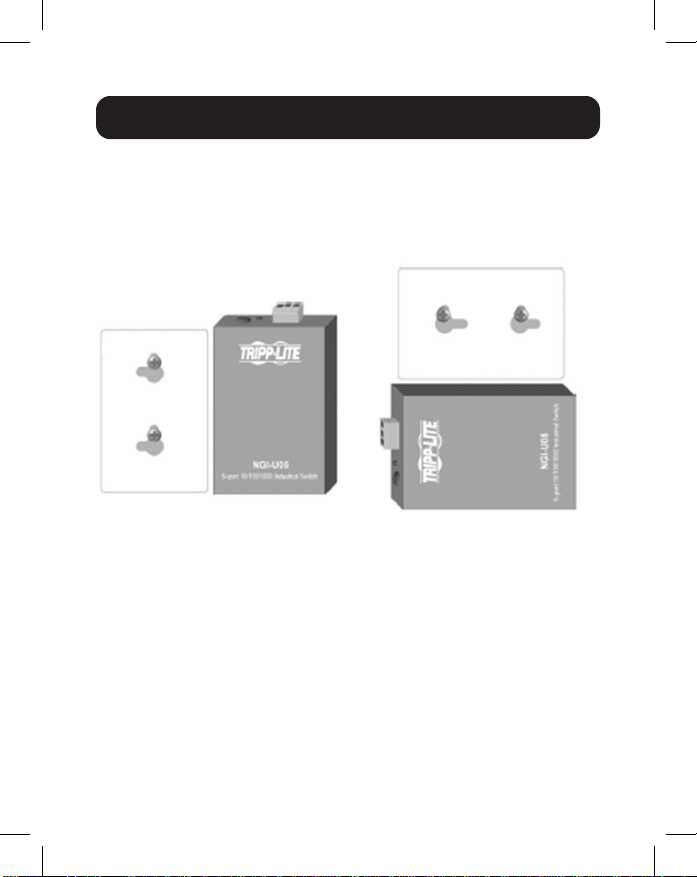
NGI-U05
Optional Accessories
• N001-Series Cat5e 350 MHz Snagless UTP Cables
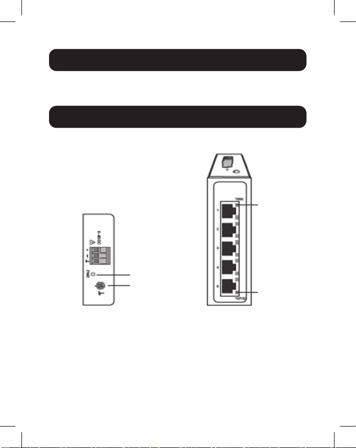
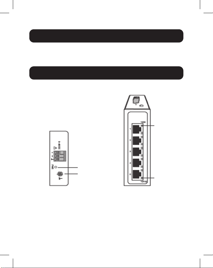
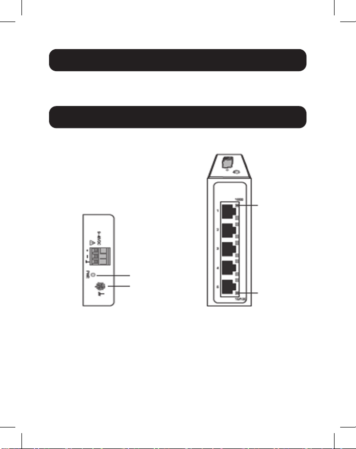
Product Overview
Top View Front View
10/100
1000 Mbps
Grounding
Screw
Power

4
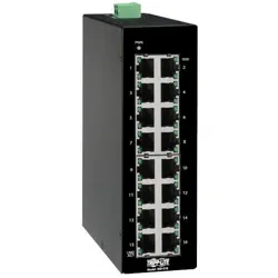
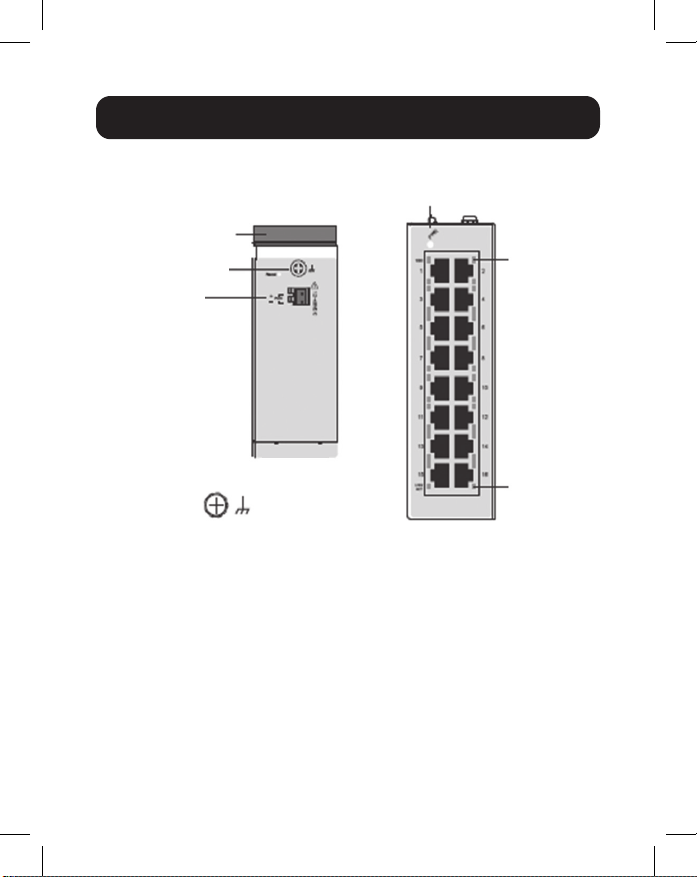
Product Overview
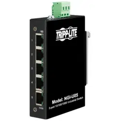
NGI-U16
Top View
Front View
Grounding Screw
DIN Rail
Grounding
Screw
LNK/ACT
PWR
1000 Mbps
Power Input
Terminal
Block

5
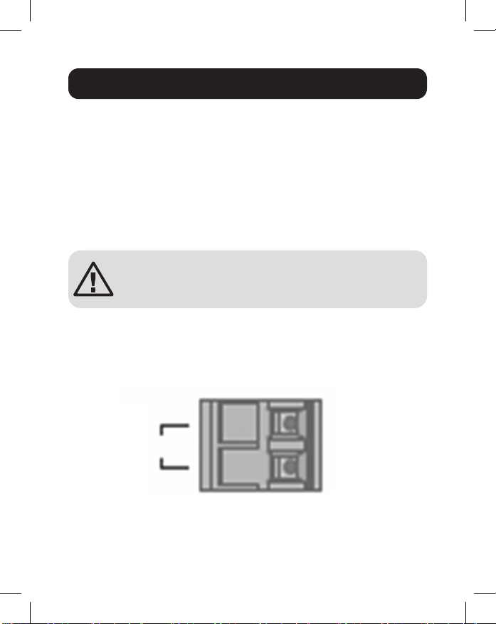
ATTENTION: The NGI-U05 and NGI-U16 are open-
type devices and shall be DIN mounted or wall
mounted (NGI-U05 only) in a rack enclosure. The
ambient temperature should not exceed 75°C
(167°F).
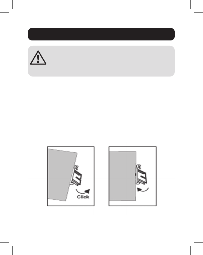
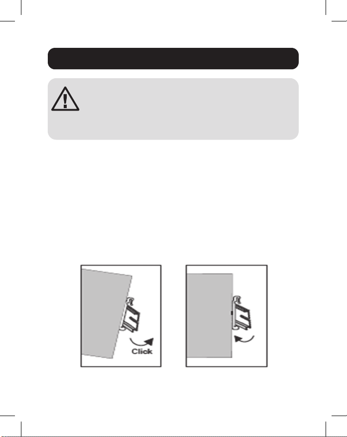
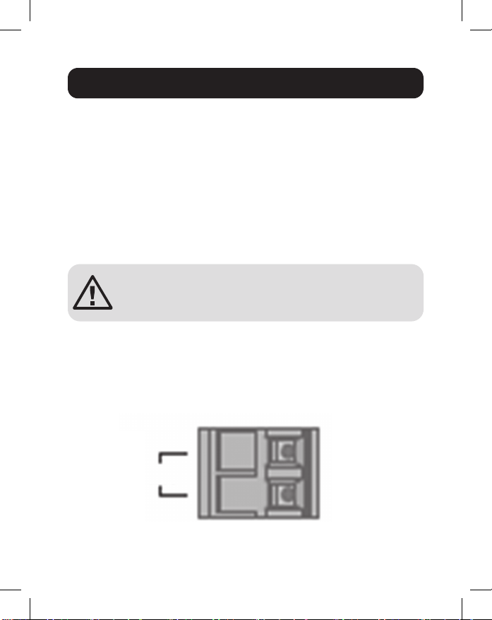
Mounting the Switch
Place the switch on the DIN rail from above using the built-in
slot. Push the front of the switch toward the mounting surface
until it snaps into place. You will hear a “click” to indicate it has
successfully snapped into place.
Dismounting the Switch
Press the switch from the top, then pull out the lower edge of
the switch to remove it from the DIN rail.
DIN Mounting/Dismounting Instructions
Mounting
the Switch
Removing
the Switch
6
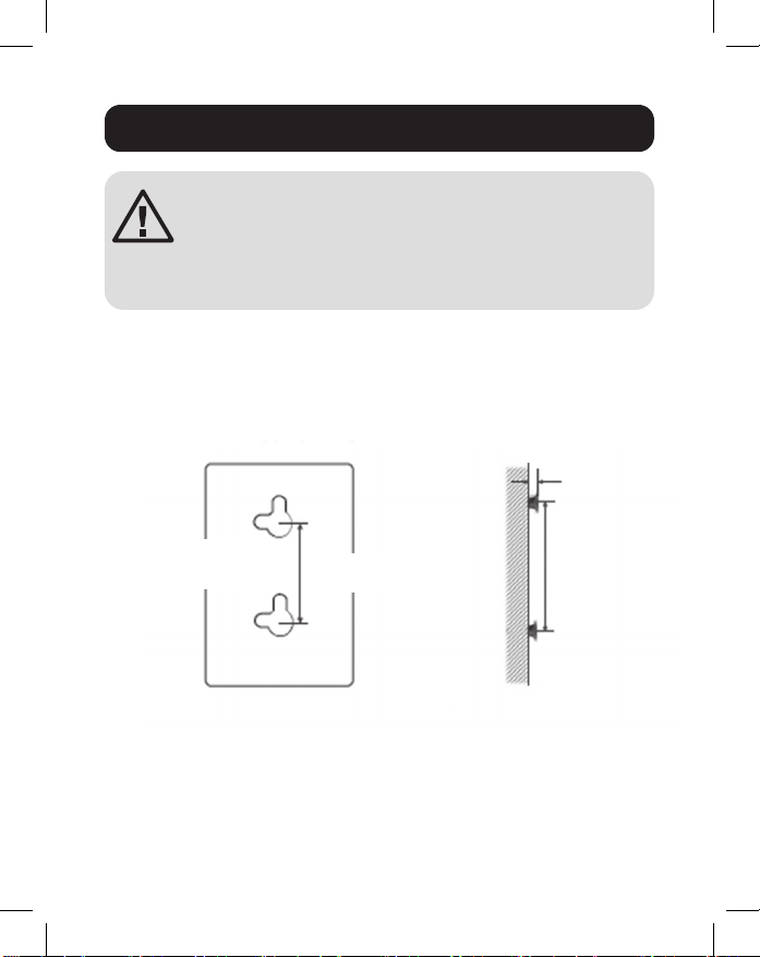
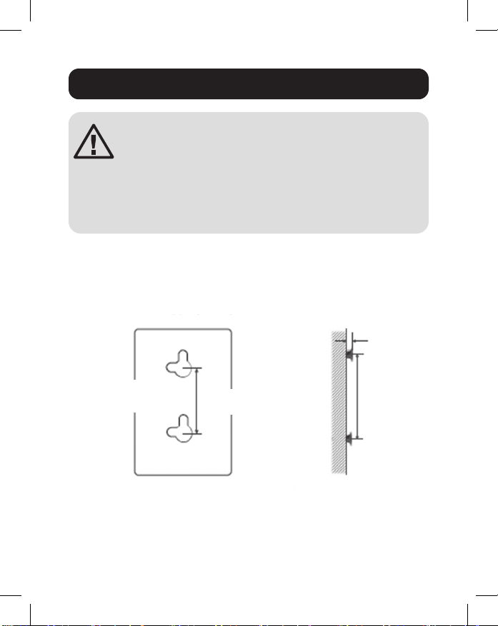
DIN Mounting/Dismounting Instructions
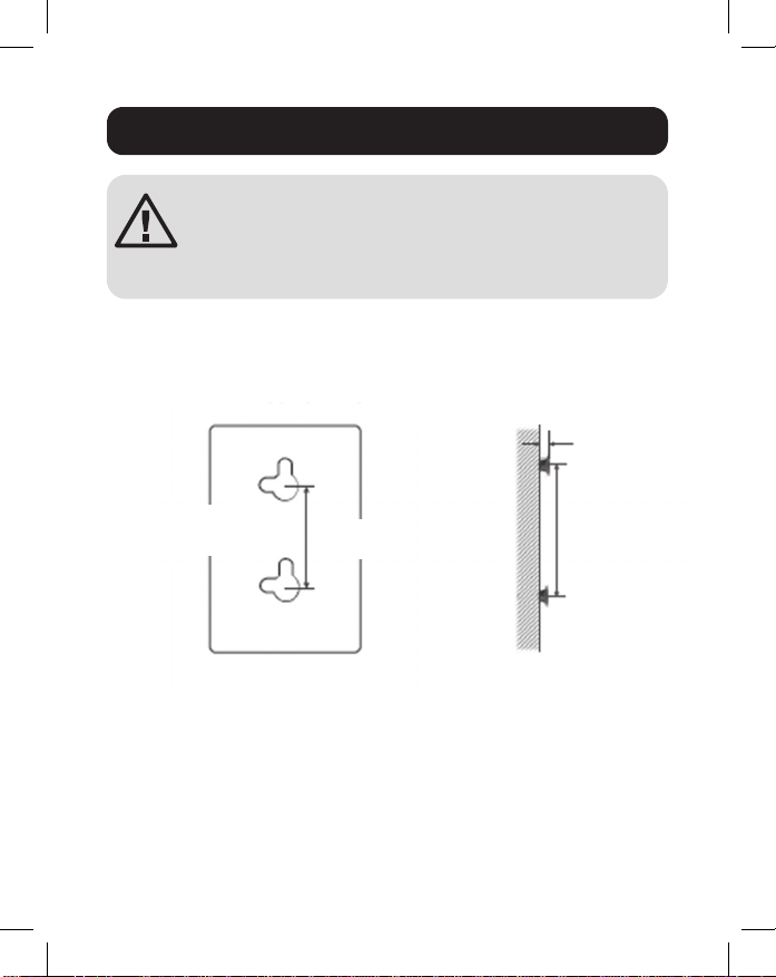
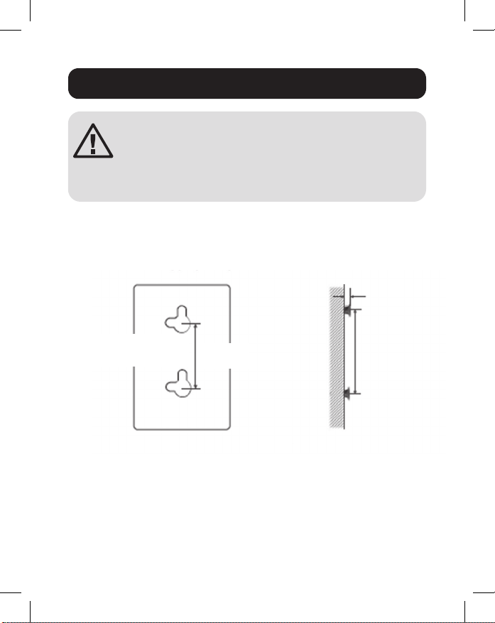
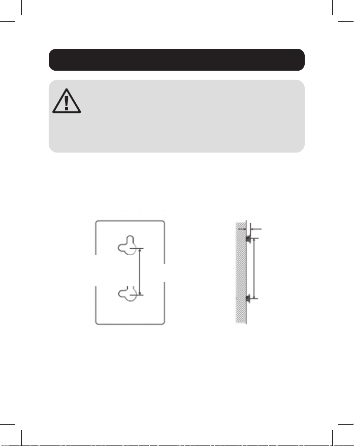
Wall-Mounted Mask (NGI-U05 Only)
1. Mount the switch by using mounting holes on the wall at the
appropriate places.
Mounting Holes
Drawing of NGI-U05
Screw Installation
Distance
Mounting holes
for switch
50 mm
1.5 mm - 3 mm
50 mm
ATTENTION: A corrosion-free DIN mounting rail is
advisable. When mounting the switch, be sure to
allow enough space between devices to install the
cabling and to ensure proper airow.
7
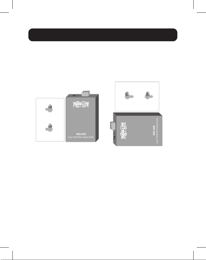
2. The switch can be wall mounted either vertically or
horizontally.
Note: Horizontal mounting is not evaluated by UL.
Grounding the Switch
Grounding and wire routing help limit the eects of line noise
caused by electromagnetic interference (EMI). Run the ground
connection from the ground screw to the grounding surface
prior to connecting devices.
ATTENTION: This switch is intended for mounting on a
well-grounded surface, such as a metal panel.
DIN Mounting/Dismounting Instructions
Mounting direction with screw
Straight Direction
Installation
Horizontal Direction
Installation
(Horizontal direction is
not evaluated by UL)
Mounting direction with screw

8
WARNING: Safety measures should be taken before
connecting the power cable. Turn o the power before
connecting modules or wires. The correct power supply
voltage is listed on the product label. Check the voltage of your
power source to make sure you are using the correct voltage.
DO NOT use a voltage greater than what is specied on the
product label. Calculate the maximum possible current in each
power wire and common wire. Observe all electrical codes
dictating the maximum current allowable for each wire size. If
current exceeds the maximum rating, the wiring can overheat,
causing serious damage to your equipment.
Please read and follow these guidelines:
• Use separate paths to route wiring for power and devices. If
power wiring and device wiring paths must cross, make sure
the wires are perpendicular at the intersection point.
Note: Do not run signal or communications wiring and power wiring
through the same wire conduit. To avoid interference, wires with
dierent signal characteristics should be routed separately.
• You can use the type of signal transmitted through a wire
to determine which wires should be kept separate. Wiring
that shares similar electrical characteristics can be bundled
together.
• You should separate input wiring from output wiring.
• Be advised that you should label the wiring to all devices in
the system.
Wiring Requirements

9
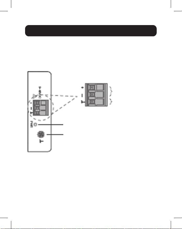
Wiring Power Input
NGI-U05 with 3-Pin Terminal Block
Check the polarity while connecting. Top view of the Terminal
Block is shown in the gure below:
CAUTION:
• Use copper conductors only.
• Wiring cable temperature should support at least 105°C.
• Tighten the wire to a torque value 4.5 lb.in.
• The wire gauge for the terminal block should range between
12 and 24 AWG.
Wiring Requirements
Power
Grounding Screw
Power Input
Terminals
Grounding
Terminals
10
To insert power wire and connect the 9~48VDC at a maximum
of 0.5A DC power to the power terminal block, follow these
steps:
• Use a at-head screwdriver to loosen the wire-clamp screws.
• Insert the negative/positive DC wires into the ( - / + )
terminals, respectively.
• Tighten the wire-clamp screws to prevent the wires from
loosening.
ATTENTION: Use a power supply from 9~48VDC.
The device power shall be supplied by SELV
circuit.
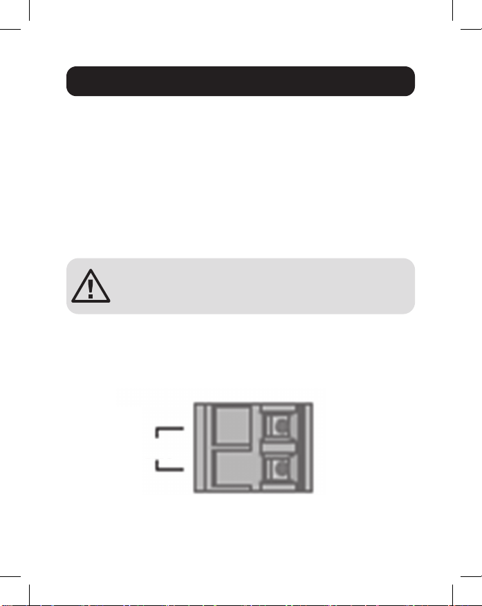
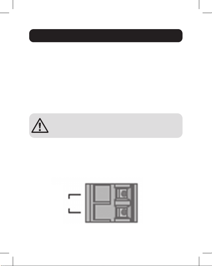
NGI-U16 with 2-Pin Terminal Block
You can use “PWR” for power input. Top view of the Terminal
Block is shown in the gure below:
Wiring Requirements
PWR
12~48VDC
Terminal Block
-
+
11
CAUTION:
• Use copper conductors only.
• Wiring cable temperature should support at least 105°C.
• Tighten the wire to a torque value 4.5 lb.in.
• The wire gauge for the terminal block should range between
12 and 24 AWG.
To insert power wire and connect the 12~48VDC at a
maximum of 1.5A DC power to the power terminal block, follow
these steps:
• Use a at-head screwdriver to loosen the wire-clamp screws.
• Insert the negative/positive DC wires into the PWR-/PWR+
terminals, respectively.
• Tighten the wire-clamp screws to prevent the wires from
loosening.
ATTENTION: Use a power supply from 12~48VDC.
The device power shall be supplied by SELV
circuit.
Wiring Requirements

12
Connect one end of an RJ45 Ethernet cable (see Optional
Accessories) into the switch’s RJ45 Ethernet port. Connect
the other end to a network device. Cat5e cable or above is
recommended.
All ports support Fast Ethernet and 10/100/1000 Ethernet
(10/100/1000Base-T), as well as auto-negotiation and auto
MDI/MDI-X to eliminate the need for crossover cabling.
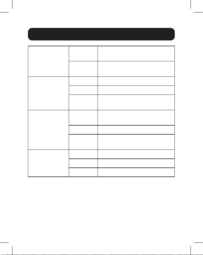
LED Indicators
Cabling
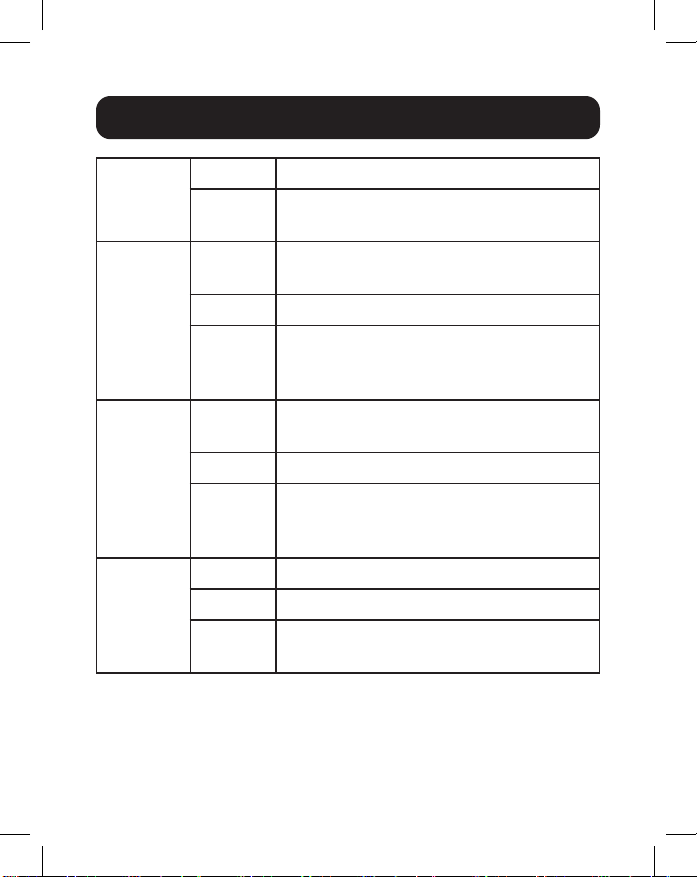
13
PWR (Green) Illuminated Power on by Terminal Block
PWR
O Terminal Block PWR fails or is
unavailable
1000 (Green) Illuminated Link speed is 1000 Mbps (1 Gb)
Blinking Data is transmitting/receiving
O Link speed is 10/100 Mbps or
link failed
10/100 (Green) Illuminated Copper port link-up at 10/100
Mbps
Blinking Data is transmitting/receiving
O Link speed is 1000 Mbps (1 Gb)
or link failed
LNK/ACT
(Green)
Illuminated Ethernet link-up
Blinking Data is transmitting/receiving
O Port disconnected or link failed
Note
:
10/100 LED only on NGI-U05. LINK/ACT LED only on NGI-U16.
Speed LED (100/1000) blinking function only on NGI-U05.
LED Indicators
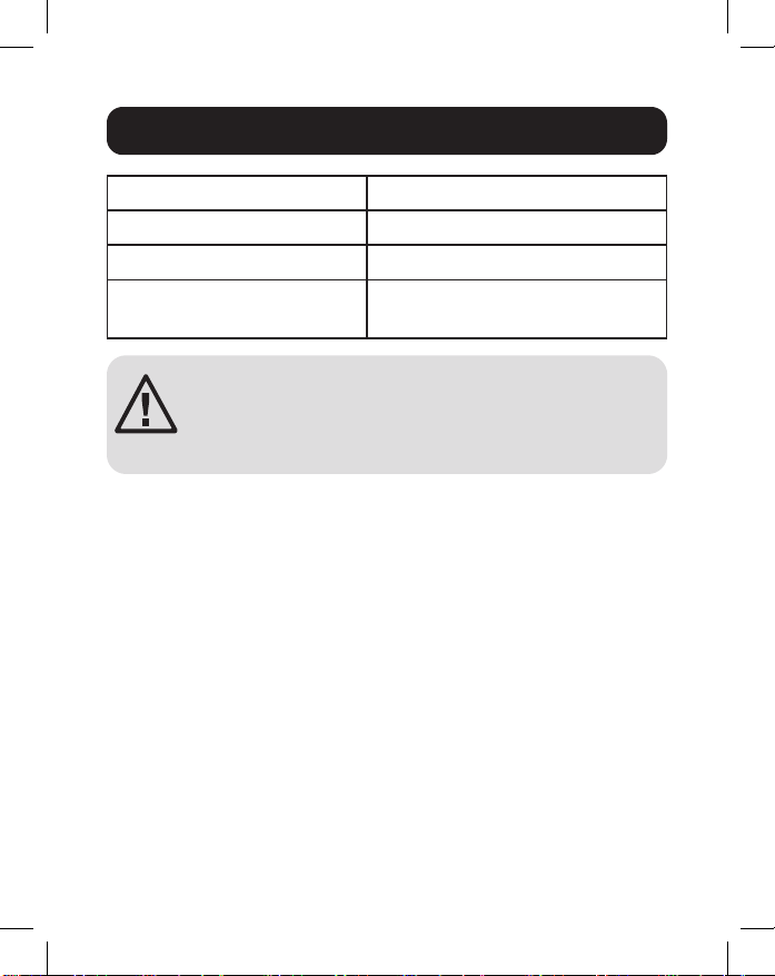
14
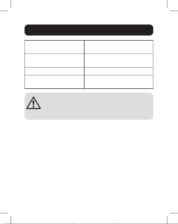
Operating Temperature -40°C to 75°C (-40°F to 167°F)
Storage Temperature -40°C to 85°C (-40°F to 185°F)
Maximum Altitude 2000 m
Ambient Relative Humidity 5 to 95% (Non-Condensing)
ATTENTION: If the switch is used in a manner
not specied here, the protection provided by the
switch may be impaired.
Environmental
15
3-Year Limited Warranty
Seller warrants this product, if used in accordance with all applicable instructions, to be
free from original defects in material and workmanship for a period of three (3) years
from the date of initial purchase. If the product should prove defective in material or
workmanship within that period, Seller will repair or replace the product, at its sole
discretion.
THIS WARRANTY DOES NOT APPLY TO NORMAL WEAR OR TO DAMAGE
RESULTING FROM ACCIDENT, MISUSE, ABUSE OR NEGLECT. SELLER
MAKES NO EXPRESS WARRANTIES OTHER THAN THE WARRANTY
EXPRESSLY SET FORTH HEREIN. EXCEPT TO THE EXTENT PROHIBITED BY
APPLICABLE LAW, ALL IMPLIED WARRANTIES, INCLUDING ALL WARRANTIES
OF MERCHANTABILITY OR FITNESS, ARE LIMITED IN DURATION TO THE
WARRANTY PERIOD SET FORTH ABOVE; AND THIS WARRANTY EXPRESSLY
EXCLUDES ALL INCIDENTAL AND CONSEQUENTIAL DAMAGES. (Some states do
not allow limitations on how long an implied warranty lasts, and some states do not
allow the exclusion or limitation of incidental or consequential damages, so the above
limitations or exclusions may not apply to you. This warranty gives you specic legal
rights, and you may have other rights which vary from jurisdiction to jurisdiction.)
WARNING: The individual user should take care to determine prior to use whether this
device is suitable, adequate or safe for the use intended. Since individual applications
are subject to great variation, the manufacturer makes no representation or warranty as
to the suitability or tness of these devices for any specic application.
Product Registration
Visit tripplite.com/warranty today to register your new Tripp Lite product. You’ll be
automatically entered into a drawing for a chance to win a FREE Tripp Lite product!*
*No purchase necessary. Void where prohibited. Some restrictions apply. See website for
details.
WEEE Compliance Information for Tripp Lite Customers and Recyclers
(European Union)
Under the Waste Electrical and Electronic Equipment (WEEE) Directive and
implementing regulations, when customers buy new electrical and electronic
equipment from Tripp Lite, they are entitled to:
• Send old equipment for recycling on a one-for-one, like-for-like basis (this varies
depending on the country)
• Send the new equipment back for recycling when this ultimately becomes waste
Warranty and Product Registration

16
Warranty and Product Registration
FCC Notice, Class B
This device complies with part 15 of the FCC Rules. Operation is subject to the
following two conditions: (1) This device may not cause harmful interference, and (2)
this device must accept any interference received, including interference that may
cause undesired operation.
Note: This equipment has been tested and found to comply with the limits for a Class
B digital device, pursuant to part 15 of the FCC Rules. These limits are designed to
provide reasonable protection against harmful interference in a residential installation.
This equipment generates, uses and can radiate radio frequency energy and, if not
installed and used in accordance with the instructions, may cause harmful interference
to radio communications. However, there is no guarantee that interference will not
occur in a particular installation. If this equipment does cause harmful interference to
radio or television reception, which can be determined by turning the equipment o
and on, the user is encouraged to try to correct the interference by one or more of the
following measures:
• Reorient or relocate the receiving antenna.
• Increase the separation between the equipment and receiver.
• Connect the equipment into an outlet on a circuit dierent from that to which the
receiver is connected.
• Consult the dealer or an experienced radio/TV technician for help.
Any changes or modications to this equipment not expressly approved by Tripp Lite
could void the user’s authority to operate this equipment.
Use of this equipment in life support applications where failure of this equipment
can reasonably be expected to cause the failure of the life support equipment or to
signicantly aect its safety or eectiveness is not recommended.
Tripp Lite has a policy of continuous improvement. Specications are subject to change
without notice. Photos and illustrations may dier slightly from actual products.
1111 W. 35th Street, Chicago, IL 60609 USA • tripplite.com/support
21-02-223 • 93-3E2B_RevA

17
Switches Gigabit
Ethernet Industriales no
Administrados, Conectar y
Usar, Instalables
Modelos: NGI-U05, NGI-U16
1111 W. 35th Street, Chicago, IL 60609 USA • tripplite.com/support
Copyright © 2022 Tripp Lite. Todos los derechos reservados.
Manual del Propietario
English 1 • Français 33 • Русский 49 • Deutsch 65

18
• Switch Ethernet Gigabit NGI-U05 o NGI-U16
• Manual del Propietario
Contenido del Empaque
Características del Producto
• 5 puertos (NGI-U05) o 16 (NGI-U16) RJ45 de negociación
automática de 10/100/1000 Mbps
• Soporta la función de detección automática de cruce MDI /
MDI-X
• Soporta un rango de temperatura de operación de -40 °C a
75 °C [-40 °F a 167 °F]
• Los LEDs de fácil lectura indican el estado de conexión y
actividad para cada puerto
• • Cumple con los siguientes estándares de IEEE:
• IEEE 802.3 10Base-T
• IEEE 802.3u 100Base-T
• IEEE 802.3ab 1000Base-T
• IEEE 802.3 Negociación Automática
• IEEE 802.3x Control de Flujo
• Soporta aprendizaje automático y envejecimiento automático
de la dirección MAC
• El durable clip para riel preinstalado se ja rmemente en
cualquier riel DIN estándar de 35 mm*
• Instalación y operación simples para conectar y usar, sin
necesidad de conguración
*Nota: Solo NGI-U05 es instalable en DIN y en la pared
19
NGI-U05
Accesorios Opcionales
• Cables UTP Snagless de 350 MHz Cat5e Serie N001
Vista General del Producto
Vista Superior Vista Frontal
10/100
1000 Mbps
Tornillo de
Conexión a
Tierra
Alimentación

20
Vista General del Producto
NGI-U16
Vista Superior
Vista Frontal
Tornillo de
Conexión a Tierra
Riel DIN
Grounding
Screw
LNK/ACT
PWR
1000 Mbps
Bloque de
Terminales
de Entrada
de Energía
21
ATENCIÓN: El NGI-U05 y el NGI-U16 son dispositivos
de tipo abierto y deben ser instalados en DIN o
pared (solo NGI-U05) en un gabinete. La temperatura
ambiente no debe exceder 75 °C [167 °F].
Instalación del Switch
Coloque el switch en el riel DIN desde arriba usando la ranura
incorporada. Empuje el frente del switch hacia la supercie de
instalación hasta que encaje en su sitio. Escuchará un “clic”
para indicar que se ha insertado correctamente en su lugar.
Desinstalación del Switch
Presione el switch de la parte superior, después jale del borde
inferior del switch para retirarlo del riel DIN.
Instrucciones para Instalación y Desinstalación en Din
Instalación
del Switch
Retiro
del Switch
22
Instrucciones para Instalación y Desinstalación en Din
Máscara para Instalación en Pared (NGI-U05
Solamente)
1. Instale el switch usando oricios de instalación en la pared
en los lugares apropiados.
Dibujo de Oricios
de Instalación de
NGI-U05
Distancia de
Instalación del
Tornillo
Oricios de instalación
para switch
50 mm
1.5 mm - 3 mm
50 mm
ATENCIÓN: Se recomienda un riel de instalación
DIN que no presente corrosión. Al instalar el
switch, asegúrese de permitir suciente espacio
entre dispositivos para instalar el cableado y
asegurar el ujo de aire adecuado.

23
2. El switch puede instalarse vertical u horizontalmente en la
pared.
Nota: La instalación horizontal no ha sido evaluada por UL.
Conexión a Tierra del Switch
La conexión a tierra y el enrutamiento del cable ayudan
a limitar los efectos del ruido en la línea causado por
interferencia electromagnética [EMI]. Conduzca la conexión a
tierra desde el tornillo de tierra a la supercie aterrizada antes
de conectar los dispositivos.
ATENCIÓN: Este switch está diseñado para instalarse en
una supercie de instalación bien aterrizada, como un panel
metálico.
Instrucciones para Instalación y Desinstalación en Din
Dirección de instalación
con tornillo
Instalación en
Dirección Recta
Instalación en
Dirección Horizontal
(La dirección horizontal no ha
sido evaluada por UL)
Dirección de instalación
con tornillo

24
ADVERTENCIA: Antes de conectar el cable de alimentación,
deben implementarse medidas de seguridad. Apague la energía
antes de conectar cualquier módulo o cable. El voltaje de
alimentación correcto se indica en la etiqueta del producto.
Compruebe el voltaje de su fuente de alimentación para
asegurarse de que está usando el voltaje correcto. NO utilice un
voltaje superior al especicado en la etiqueta del producto. Calcule
la corriente máxima posible en cada cable de alimentación y el
cable común. Tome en cuenta todos los códigos eléctricos que
dicten la corriente máxima permitida para cada tamaño de cable.
Si la corriente excede la especicación máxima, el cableado puede
sobrecalentarse causando serios daños a su equipo.
Lea y siga estas pautas:
• Use rutas separadas para conducir el cableado para
energía y dispositivos. Si el cableado de alimentación y las
trayectorias de cableado del dispositivo deben cruzarse,
asegúrese de que los cables sean perpendiculares en el
punto de intersección.
Nota: No conduzca un cableado de señal o comunicaciones y el
cableado de alimentación a través del mismo conducto de cable.
Para evitar interferencia, los cables con diferentes características de
señal deben tenderse por separado.
• Puede usar el tipo de señal transmitida a través de un cable para
determinar qué cables deben mantenerse separados. El cableado
que comparte características eléctricas similares puede agruparse.
• Debe separar el cableado de entrada del cableado de salida.
• Tenga en cuenta que debe etiquetar el cableado a todos los
dispositivos del sistema.
Requerimientos de Cableado
25
Entrada de Alimentación del Cableado
NGI-U05 con Bloque de Terminales de 3 Pines
Mientras conecta, compruebe la polaridad. La vista superior
del bloque de terminales se muestra en la siguiente gura:
PRECAUCIÓN:
• Use únicamente conductores de cobre.
• La temperatura del conductor de cableado debe soportar al
menos 105 °C.
• Apriete el cable a un valor de 4.5 lb•pulg.
• El calibre del cable para el bloque de terminales debe oscilar
entre 4 ~ 0.25 mm2 [12AWG ~ 24AWG].
Requerimientos de Cableado
Alimentación
Tornillo de Conexión a Tierra
Terminales de
Entrada de Energía
Terminales de
Conexión a Tierra
26
Para insertar el cable de alimentación y conectar la energía
de CD de 9VCD ~ 48VCD a un máximo de 0.5A al bloque de
terminales de alimentación, siga estos pasos:
• Use un desatornillador de cabeza plana para aojar los
tornillos de la abrazadera del cable.
• Inserte los cables de CD negativos y positivos en las
terminales (- y +), respectivamente.
• Apriete los tornillos de abrazadera del cable para evitar que
los cables se aojen.
ATENCIÓN: Use una fuente de alimentación de
9VCD ~ 48VCD. La energía del dispositivo debe
ser alimentada por el circuito SELV.
NGI-U16 con Bloque de Terminales de 2 Pines
Puede usar “PWR” para entrada de energía. La vista superior
del bloque de terminales se muestra en la siguiente gura:
Requerimientos de Cableado
PWR
12~48VDC
Bloque de Terminales
-
+
27
PRECAUCIÓN:
• Use únicamente conductores de cobre.
• La temperatura del conductor de cableado debe soportar al
menos 105 °C.
• Apriete el cable a un valor de apriete de 4.5 lb-in.
• El calibre del cable para el bloque de terminales debe oscilar
entre 4 ~ 0.25 mm2 [12AWG ~ 24AWG].
Para insertar el cable de alimentación y conectar la energía
de CD de 12VCD ~ 48VCD a un máximo de 1.5A al bloque de
terminales de alimentación, siga estos pasos:
• Use un desatornillador de cabeza plana para aojar los
tornillos de la abrazadera del cable.
• Inserte los cables de CD negativos y positivos en las
terminales PWR- y PWR+, respectivamente.
• Apriete los tornillos de abrazadera del cable para evitar que
los cables se aojen.
ATENCIÓN: Use una fuente de alimentación de
12VCD ~ 48VCD. La energía del dispositivo debe
ser alimentada por el circuito SELV.
Requerimientos de Cableado

28
Conecte un extremo de un cable Ethernet RJ45 (ver
Accesorios Opcionales) en el puerto Ethernet RJ45 del
switch. Conecte el otro extremo a un dispositivo de red. Se
recomienda un cable Cat5e o superior.
Todos los puertos soportan Fast Ethernet y Ethernet
10/100/1000 (10/100/1000Base-T), así como negociación
automática y MDI/MDI-X automática para eliminar la necesidad
de cableado cruzado.
Cableado

29
PWR
(Verde)
Iluminado Encendido por Bloque de
Terminales PWR
Apagado PWR del bloque de terminales falla
o no está disponible
1000
(Verde)
Iluminado La velocidad de enlace es de
1000 Mbps (1 Gb)
Destellando Los datos se están transmitiendo /
recibiendo.
Apagado La velocidad de enlace es
10/100 Mbps o enlace en falla
10/100
(Verde)
Iluminado Enlace de puerto de cobre a
10/100 Mbps
Destellando Los datos se están transmitiendo /
recibiendo.
Apagado
La velocidad de enlace es 1000 Mbps
(1 Gb) o enlace en falla
LNK/ACT
(Verde)
Iluminado Conexión Ethernet
Destellando Los datos se están transmitiendo /
recibiendo.
Apagado Puerto desconectado o enlace en
falla
Nota:
LED 10/100 solamente en NGI-U05. LED de Enlace/ACT
solamente en NGI-U16. Función de destello de LED de velocidad
(100/1000) solo en NGI-U05.
Indicadores LED
30
Temperatura de Operación -40 °C a 75 °C [-40 °F a 167 °F]
Temperatura de
Almacenamiento
-40 °C a 85 °C [-40 °F a 185 °F]
Altitud Máxima 2000 m
Humedad Relativa
Ambiental
De 5% a 95% (Sin Condensación)
ATENCIÓN: Si el switch se usa de una manera no
especicada aquí, la protección proporcionada
por el switch puede verse afectada.
Ambiental

31
Garantía Limitada de 3 años
El vendedor garantiza que este producto, si se usa de acuerdo con todas las
instrucciones aplicables, está libre de defectos en cuanto a materiales y mano de obra
por un período de tres (3) años a partir de la fecha de compra inicial. Si el producto
resulta defectuoso en cuanto a materiales o mano de obra dentro de ese período, el
vendedor reparará o reemplazará el producto a su entera discreción.
ESTA GARANTÍA NO SE APLICA AL DESGASTE NORMAL O A LOS DAÑOS
QUE RESULTEN DE ACCIDENTES, USO INCORRECTO, USO INDEBIDO O
NEGLIGENCIA. EL VENDEDOR NO OTORGA GARANTÍAS EXPRESAS DISTINTAS A
LA ESTIPULADA EN EL PRESENTE. SALVO EN LA MEDIDA EN QUE LO PROHÍBAN
LAS LEYES APLICABLES, TODAS LAS GARANTÍAS IMPLÍCITAS, INCLUIDAS
TODAS LAS GARANTÍAS DE COMERCIALIZACIÓN O IDONEIDAD, ESTÁN
LIMITADAS EN CUANTO A DURACIÓN AL PERÍODO DE GARANTÍA ESTABLECIDO;
ASIMISMO, ESTA GARANTÍA EXCLUYE EXPRESAMENTE TODOS LOS DAÑOS
INCIDENTALES E INDIRECTOS. (Algunos estados no permiten limitaciones en cuanto
a la duración de una garantía y algunos estados no permiten la exclusión o limitación de
daños incidentales o indirectos, de modo que es posible que las limitaciones anteriores
no se apliquen a usted. Esta garantía le otorga derechos legales especícos y es
posible que le asistan otros derechos que pueden variar de una jurisdicción a otra).
ADVERTENCIA: antes de usarlo, cada usuario debe tener cuidado al determinar si
este dispositivo es adecuado o seguro para el uso previsto. Ya que las aplicaciones
individuales están sujetas a gran variación, el fabricante no garantiza la adecuación de
estos dispositivos para alguna aplicación especíca.
Información de Cumplimiento con WEEE para Clientes y Recicladores
de Tripp Lite (Unión Europea)
Conforme a la Directiva de Residuos de Equipos Eléctricos y Electrónicos
[WEEE] y las regulaciones aplicables, al adquirir un equipo eléctrico y
electrónico nuevo de Tripp Lite, los clientes están obligados a:
• Enviar para reciclaje equipos viejos del mismo tipo y en el mismo número (esto
varía de un país a otro)
• Devolver el equipo nuevo para nes de reciclaje una vez que nalmente se
convierta en residuo
Registro de la Garantía y del Producto

32
Registro de la Garantía y del Producto
No se recomienda el uso de este equipo en aplicaciones de soporte de vida en donde
razonablemente se pueda esperar que la falla de este equipo cause la falla del equipo
de soporte de vida o afecte signicativamente su seguridad o efectividad.
Tripp Lite tiene una política de mejora continua. Las especicaciones están sujetas a
cambio sin previo aviso. Las fotografías e ilustraciones pueden diferir ligeramente de los
productos reales.
1111 W. 35th Street, Chicago, IL 60609 USA • tripplite.com/support
21-02-223 • 93-3E2B_RevA

33
Commutateurs Gigabit
Ethernet industriels non
gérés, prêt à l'emploi,
montables
Modèles : NGI-U05, NGI-U16
1111 W. 35th Street, Chicago, IL 60609 USA • tripplite.com/support
Droits d'auteur © 2022 Tripp Lite. Tous droits réservés.
Manuel de l'utilisateur
English 1 • Español 17 • Русский 49 • Deutsch 65

34
• Commutateur Ethernet Gigabit NGI-U05 ou NGI-U16
• Manuel de l’utilisateur
Contenu de l’emballage
Caractéristiques du produit
• 5 ports RJ45 10/100/1000 Mbps auto-négociables (NGI-U05) or
16 ports RJ45 10/100/1000 Mbps auto-négociables (NGI-U16)
• Prend en charge la fonction de croisement automatique MDI/
MDI-X
• Prend en charge une plage de températures de
fonctionnement variant de -40 à 75 °C (-40 à 167 °F)
• Les voyants à DEL faciles à lire indiquent la connexion et
l’état de l’activité pour chaque port.
• Répond aux normes IEEE suivantes :
• IEEE 802.3 10Base-T
• IEEE 802.3u 100Base-T
• IEEE 802.3ab 1000Base-T
• IEEE 802.3 Auto-négociation
• IEEE 802.3x Contrôle de ux
• Prend en charge l’apprentissage automatique et le
vieillissement automatique des adresses MAC
• L’agrafe de rail durable préinstallée s’adapte fermement à
n’importe quel rail DIN standard de 35 mm*
• Installation simple prête à l’emploi et fonctionnement sans
aucune conguration requise
*Remarque : Seul NGI-U05 peut-être monté DIN et au mur
35
NGI-U05
Accessoires en option
• Câbles UTP anti-coupure de 350 MHz Cat5e de la série
N001
Aperçu du produit
Vue de dessus Vue avant
10/100
1000 Mbps
Vis de mise à
la masse
Alimentation
36
Aperçu du produit
NGI-U16
Vue de dessus
Vue avant
Vis de mise à la
masse
Rail DIN
Vis de mise
à la masse
LNK/ACT
PWR
1000 Mbps
Bloc de
jonction
de l’entrée
d’alimentation
37
ATTENTION : Le NGI-U05 et NGI-U16 sont des
dispositifs de type ouvert et doivent être montés sur
DIN ou au mur (NGI-U05 seulement) dans un boîtier
pour bâti. La température ambiante ne doit pas
excéder 75 °C (167 °F).
Montage du commutateur
Placer le commutateur sur le rail DIN du dessus en utilisant
la fente intégrée. Pousser l’avant du commutateur vers la
surface de montage jusqu’à ce qu’il s’enclenche en place. Un
« clic » se fera entendre pour indiquer qu’il a été correctement
enclenché en place.
Démontage du commutateur
Appuyer sur le commutateur depuis le haut, puis tirer sur le
bord inférieur du commutateur pour le retirer du rail DIN.
Instructions de montage/démontage pour le rail DIN
Montage du
commutateur
Retrait du
commutateur
38
Instructions de montage/démontage pour le rail DIN
Masque mural (NGI-U05 seulement)
1. Monter le commutateur en utilisant des trous de montage
au mur aux endroits appropriés.
Dessin des trous de
montage de NGI-U05
Distance d’installation
des vis
Trous de montage
pour commutateur
50 mm
1.5 mm - 3 mm
50 mm
ATTENTION : Un rail de montage DIN exempt de
corrosion est recommandé. Lors du montage du
commutateur, s’assurer de laisser susamment
d’espace entre les appareils pour installer le
câblage et assurer un bon débit d’air.
39
2. Le commutateur peut être monté au mur verticalement ou
horizontalement.
Remarque : le montage Horizontal n’est pas évalué par UL.
Mise à la terre du commutateur
La mise à la terre et le cheminement des ls aident à limiter
les eets du bruit de ligne causé par les interférences
électromagnétiques (EMI). Acheminer la mise à la masse de la
vis de mise à la terre à la surface de mise à la terre avant de
raccorder les dispositifs.
ATTENTION : Ce commutateur est conçu pour être monté
sur une surface bien mise à la terre, comme un panneau
métallique.
Instructions de montage/démontage pour le rail DIN
Direction de montage
avec vis
Installation dans
le sens droit
Installation dans
la direction horizontale
(la direction horizontale n’est pas
évaluée par UL)
Direction de montage
avec vis

40
AVERTISSEMENT :
Des mesures de sécurité doivent être prises
avant de raccorder le câble d’alimentation. Couper l’alimentation
avant de connecter des modules ou des ls. La bonne tension
d’alimentation gure sur l’étiquette du produit. Vérier la tension
de la source d’alimentation pour s’assurer qu’il s’agit de la bonne
tension à utiliser. NE PAS utiliser une tension supérieure à celle
qui gure sur l’étiquette du produit. Calculer le courant maximum
possible dans chaque l d’alimentation et chaque l commun.
Respecter tous les codes de l’électricité dictant le courant
maximum autorisé pour chaque taille de l. Si le courant excède
les valeurs nominales maximales, le câblage risque de surchauer
et de causer des dommages importants à l’équipement.
Lire et suivre les directives suivantes :
• Utiliser des chemins distincts pour acheminer le câblage
pour l’alimentation et les dispositifs. Si les chemins du
câblage d’alimentation et du câblage des dispositifs doivent
se croiser, s’assurer que les ls sont perpendiculaires au
point d’intersection.
Remarque:
Ne pas acheminer le câblage du signal ou des
communications et le câblage de l’alimentation à travers le même conduit
de ls. Pour éviter l’interférence, les ls avec diérentes caractéristiques
d’émission de signaux doivent être acheminés séparément.
• Un type de signal transmis par le biais d’un l peut être utilisé
pour déterminer quels ls devraient être gardés séparés.
Le câblage qui partage des caractéristiques électriques
similaires peut être groupé.
• Le câblage d’entrée doit être distinct du câblage de sortie.
• Veuillez étiqueter le câblage de tous les appareils du système.
Exigences relatives au câblage

41
Câblage de l’alimentation d’entrée
NGI-U05 avec bloc de jonction à 3 broches
Vérier la polarité lors de la connexion. La vue supérieure du
bloc de jonction est illustrée sur la gure ci-dessous :
MISE EN GARDE :
• Utiliser des connecteurs en cuivre uniquement.
• La température du câble de câblage devrait supporter au
moins 105 °C.
• Serrer le l à une valeur de couple de 4,5 lb•po
• Le calibre du l pour le bloc de jonction devrait se situer
entre 12 et 24 AWG.
Exigences relatives au câblage
Vis de mise à la masse
Bloc de jonction de l’entrée d’alimentation
Bornes d’entrée
d’alimentation
Bornes de mise
à la terre
42
Pour insérer le l d’alimentation et raccorder le 9~48 VCC à
une alimentation CC de 0,5 A maximum au bloc de jonction
d’alimentation, suivre les étapes suivantes :
• Utiliser un tournevis à tête plate pour desserrer les vis du
serre-l.
• Insérer les ls CC négatifs/positifs dans les bornes (-/+),
respectivement.
• Serrer les vis du serre-l pour empêcher que les ls ne se
desserrent.
ATTENTION : Utiliser une alimentation de
9~48 VCC. L’alimentation du dispositif doit être
fournie par le circuit SELV.
NGI-U16 avec bloc de jonction à 2 broches
Il est possible d’utiliser « PWR » pour l’entrée d’alimentation.
La vue supérieure du bloc de jonction est illustrée sur la gure
ci-dessous :
Exigences relatives au câblage
PWR
12~48VDC
Bloc de jonction
-
+

43
MISE EN GARDE :
• Utiliser des connecteurs en cuivre uniquement.
• La température du câble de câblage devrait supporter au
moins 105 °C.
• Serrer le l à une valeur de couple de 4,5 lb/po.
• Le calibre du l pour le bloc de jonction devrait se situer
entre 12 et 24 AWG.
Pour insérer le l d’alimentation et raccorder le 12~48 VCC à
une alimentation CC de 1,5 A maximum au bloc de jonction
d’alimentation, suivre les étapes suivantes :
• Utiliser un tournevis à tête plate pour desserrer les vis du
serre-l.
• Insérer les ls CC négatifs/positifs dans les bornes PWR-/
PWR+, respectivement.
• Serrer les vis du serre-l pour empêcher que les ls ne se
desserrent.
ATTENTION : Utiliser une alimentation de
12~48 VCC. L’alimentation du dispositif doit être
fournie par le circuit SELV.
Exigences relatives au câblage

44
Raccorder une extrémité d’un câble Ethernet RJ45 (consulter
Accessoires en option) dans le port Ethernet RJ45 du
commutateur. Connectez l’autre extrémité à un périphérique
réseau. Le câble Cat5e ou supérieur est recommandé.
Tous les ports prennent en charge Fast Ethernet et Ethernet
10/100/1 000 (10/100/1000Base-T), ainsi que l’auto -
négociation et l’auto-MDI/MDI-X pour éliminer le besoin de
câblage croisé.
Câblage
45
PWR
(vert)
Allumé Mise sous tension par le bloc de
jonction PWR
O (hors
tension)
Le bloc de jonction PWR échoue
ou n'est pas disponible
1 000
(vert)
Allumé La vitesse de liaison est de
1 000 Mbps (1 Gb)
Clignotant Données en cours de transmission/
réception
O (hors
tension)
La vitesse de liaison est de
10/100 Mbps ou la liaison a échoué
10/100
(vert)
Allumé Connexion du port en cuivre à
10/100 Mbps
Clignotant Données en cours de transmission/
réception
O (hors
tension)
La vitesse de liaison est de
1 000 Mbps (1 Gb) ou la liaison a
échoué
LNK/ACT
(vert)
Allumé Établissement de la liaison
Ethernet
Clignotant Données en cours de transmission/
réception
O (hors
tension)
Port déconnecté ou échec de la
liaison
Remarque:
Voyant à DEL 10/100 uniquement sur NGI-U05. Voyant
à DEL LINK/ACT uniquement sur NGI-U16. Voyant à DEL de vitesse
(100/1 000) clignotant uniquement sur NGI-U05.
Voyants à DEL
46
Température de
fonctionnement
-40 à 75 °C (-40 à 167 °F)
Température d'entreposage -40 à 85 °C (-40 à 185 °F)
Altitude maximale 2 000 m
Humidité relative ambiante 5 à 95 % (sans condensation)
ATTENTION : Si le commutateur est utilisé d’une
manière non spéciée ici, la protection fournie par
le commutateur peut être compromise.
Écologique
47
Garantie limitée de 3 ans
Le vendeur garantit que ce produit, s’il est utilisé conformément à toutes les instructions
applicables, est exempt de tous défauts de matériaux et de fabrication pour une période
de trois (3) ans à partir de la date d’achat initiale. Si le produit s’avère défectueux en
raison d’un vice de matériau ou de fabrication au cours de cette période, le vendeur
s’engage à réparer ou remplacer le produit, à son entière discrétion.
CETTE GARANTIE NE S’APPLIQUE PAS À L’USURE NORMALE OU AUX
DOMMAGES RÉSULTANT D’UNE MAUVAISE UTILISATION, D’UN ABUS OU D’UNE
NÉGLIGENCE. LE VENDEUR N’ACCORDE AUCUNE GARANTIE EXPRESSE AUTRE
QUE LA GARANTIE EXPRESSÉMENT DÉCRITE DANS LE PRÉSENT DOCUMENT.
SAUF DANS LA MESURE OÙ CELA EST INTERDIT PAR LA LOI EN VIGUEUR,
TOUTE GARANTIE IMPLICITE, Y COMPRIS TOUTES LES GARANTIES DE QUALITÉ
MARCHANDE OU D’ADAPTATION, EST LIMITÉE À LA PÉRIODE DE GARANTIE
CI-DESSUS ET CETTE GARANTIE EXCLUT EXPRESSÉMENT TOUS DOMMAGES
DIRECTS ET INDIRECTS. (Certains États ne permettent pas de limitations sur la durée
d’une garantie implicite, et certains États ne permettent pas l’exclusion ou la limitation
des dommages fortuits ou consécutifs, de sorte que les limitations ou exclusions
susmentionnées peuvent ne pas s’appliquer à vous. Cette garantie vous accorde des
droits légaux spéciques, et vous pouvez avoir d’autres droits qui varient d’un territoire
à l’autre.)
AVERTISSEMENT : L’utilisateur individuel doit prendre soin de déterminer avant
l’utilisation si cet appareil est approprié, adéquat et sûr pour l’usage prévu. Puisque les
utilisations individuelles sont sujettes à des variations importantes, le fabricant ne fait
aucune déclaration ou garantie quant à l’aptitude ou l’adaptation de ces dispositifs pour
une application spécique.
Renseignements sur la conformité à la directive DEEE pour les clients
de Tripp Lite et les recycleurs (Union européenne)
En vertu de la directive et des règlements d’application relatifs aux déchets
d’équipements électriques et électroniques (DEEE), lorsque des clients
achètent de l’équipement électrique et électronique neuf de Tripp Lite, ils ont
droit :
• D’envoyer l’équipement usagé au recyclage pourvu qu’il soit remplacé par un
équipement équivalent (cela varie selon les pays)
• De retourner le nouvel équipement an qu’il soit recyclé à la n de sa vie utile
Garantie et enregistrement du produit

48
Garantie et enregistrement du produit
Il n’est pas recommandé d’utiliser cet équipement pour des appareils de survie où une
défaillance de cet équipement peut, selon toute vraisemblance, entraîner la défaillance
de l’appareil de maintien de la vie ou de nuire de façon majeure à sa sécurité ou à son
ecacité.
La politique de Tripp Lite en est une d’amélioration continue. Les caractéristiques
techniques sont modiables sans préavis. Les produits réels peuvent diérer légèrement
des photos et des illustrations.
1111 W. 35th Street, Chicago, IL 60609 USA • tripplite.com/support
21-02-223 • 93-3E2B_RevA

49
Неуправляемые
промышленные
коммутаторы Gigabit
Ethernet с подключением
по технологии Plug and Play
и возможностью монтажа
Модели: NGI-U05, NGI-U16
1111 W. 35th Street, Chicago, IL 60609 USA • tripplite.com/support
Охраняется авторским правом © 2022 Tripp Lite.
Перепечатка запрещается.
Руководство
пользователя
English 1 • Español 17 • Français 33 • Deutsch 65

50
• Коммутатор Gigabit Ethernet мод. NGI-U05 или NGI-U16
• Руководство пользователя
Содержимое упаковки
Характеристики продукта
• 5 (NGI-U05) или 16 (NGI-U16) автоматически настраиваемых
портов RJ45 (10/100/1000 Мбит/с)
• Поддержка автоматической функции перекрестного
соединения MDI/MDI-X
• Поддержка диапазона рабочих температур от -40 до 75°C
• Легко воспринимаемые светодиодные индикаторы
показывают статус подключения и активности каждого порта
• Соответствует следующим стандартам IEEE:
• IEEE 802.3 10Base-T
• IEEE 802.3u 100Base-T
• IEEE 802.3ab 1000Base-T
• IEEE 802.3 Auto Negotiation
• IEEE 802.3x Flow Control
• Поддерживает автоматическое обучение и автоматическую
тренировку по MAC-адресу
• Надежная рельсовая клемма, установленная на заводе-
изготовителе, плотно крепится к любой стандартной DIN-
рейке шириной 35 мм*
• Простота установки по технологии plug-and-play без
необходимости настройки
*Примечание. Возможность крепления на DIN-рейку и настенного
монтажа предусматривается только для модели NGI-U05

51
NGI-U05
Oпциональные кoмплектующие
• Безразрывные UTP-кабели Cat5e (350 МГц) серии N001
Kраткое описание изделия
Вид сверху Вид спереди
10/100
1000 Mbps
Заземляющий
винт
Питание

52
Kраткое описание изделия
NGI-U16
Вид сверху
Вид спереди
Заземляющий
винт
DIN-рейка
Заземляющий
винт
LNK/ACT
PWR
1000 Mbps
Блок зажимов
входного
питания

53
ВНИМАНИЕ! Модели NGI-U05 и NGI-U16 являются
устройствами открытого типа и монтируются на
DIN-рейке или стене (только мод. NGI-U05) внутри
шкафа. Температура окружающего воздуха не
должна превышать 75°C.
Крепление коммутатора
Установите коммутатор на DIN-рейку сверху, используя
встроенное гнездо. Надавите на коммутатор спереди по
направлению к монтажной поверхности до его установки
на место. Успешная установка на место фиксируется
различимым на слух “щелчком”.
Снятие коммутатора
Надавите на коммутатор сверху, а затем отсоедините его
нижний край для снятия с DIN-рейки.
Указания по креплению к DIN-рейке / снятию с DIN-рейки
Крепление
коммутатора
Снятие
коммутатора
54
Указания по креплению к DIN-рейке / снятию с DIN-рейки
Маска для настенного монтажа (только для мод.
NGI-U05)
1. Прикрепите коммутатор, используя соответствующие
монтажные отверстия в стене.
Схема монтажных
отверстий для мод.
NGI-U05
Расстояние между
крепежными винтами
Монтажные
отверстия для
коммутатора
50 mm
1.5 mm - 3 mm
50 mm
ВНИМАНИЕ! Для этой цели рекомендуется
монтажная DIN-рейка из коррозионностойкого
материала. При монтаже коммутатора
необходимо обеспечить достаточное
пространство между устройствами для прокладки
кабелей и надлежащего воздухообмена.

55
2. Коммутатор может крепиться к стене вертикально или
горизонтально.
Примечание. Горизонтальный монтаж не оценивается компанией UL.
Заземление коммутатора
Заземление и прокладка проводов помогают ограничивать
воздействие шумов в линии, вызываемых электромагнитными
помехами (ЭМП). Перед подключением устройств проведите
заземляющее соединение от винта заземления к поверхности
заземления.
ВНИМАНИЕ! Коммутатор предназначен для крепления к надежно
заземленной поверхности (например, металлической панели).
Указания по креплению к DIN-рейке / снятию с DIN-рейки
Направление монтажа с
использованием винта
Установка в прямом
направлении
Установка в горизонтальном
направлении
(горизонтальное направление не
оценивается компанией UL)
Направление монтажа с
использованием винта

56
ВНИМАНИЕ! Перед подключением кабеля питания необходимо
принять меры предосторожности. Отключайте электропитание
перед подключением модулей или проводов. Соответствующее
напряжение питания указано на маркировке изделия. Проверьте
напряжение источника питания с целью убедиться в его соответствии
установленным требованиям. НЕ используйте напряжение,
превышающее номинал, указанный на маркировке изделия.
Рассчитайте максимально возможный ток через каждый силовой
провод и нейтральный провод. Соблюдайте все электротехнические
нормы и правила, предписывающие максимально допустимый ток для
каждого калибра проводов. Превышение максимально допустимого
значения тока может привести к перегреву электропроводки,
вызывающему серьезное повреждение оборудования.
Ознакомьтесь с настоящими указаниями и следуйте им:
• Используйте раздельные маршруты прокладки силовых проводов
и проводов для соединения устройств. В случае необходимости
пересечения маршрутов прокладки силовых проводов и проводов
для соединения устройств указанные провода должны проходить
перпендикулярно друг другу в точке пересечения.
Примечание. Не прокладывайте сигнальную или слаботочную проводку
в одном кабелепроводе с силовой проводкой. Во избежание помех провода
с различными сигнальными характеристиками должны прокладываться
раздельно.
• Для определения того, какие провода следует прокладывать раздельно,
можно использовать тип сигнала, передаваемого по проводу. Провода с
аналогичными электрическими характеристиками могут объединяться в жгут.
• Входная электропроводка должна быть отделена от выходной.
• Следует обратить внимание на необходимость маркировки
проводов, прокладываемых ко всем устройствам в системе.
Требования к монтажу электропроводки

57
Монтаж силового входа
Мод. NGI-U05 с блоком 3-контактных зажимов
Проверьте полярность при подключении. Вид блока зажимов
сверху показан на приведенном ниже рисунке:
ВНИМАНИЕ!
• Используйте только медные проводники.
• Монтажный кабель должен поддерживать температуру не
менее 105°C.
• Затягивайте провода с усилием 4,5 фн•дюймы
• Примечание. При монтаже калибр проводов для блока
зажимов должен находиться в диапазоне от 12 до 24 AWG.
Требования к монтажу электропроводки
Питание
Заземляющий винт
Зажимы входного
питания
Зажимы
заземления

58
Для установки силового провода и подключения питания
напряжением 9~48 В= при максимальной мощности,
соответствующей постоянному току силой 0,5 А, к блоку
зажимов питания выполните следующие действия:
• Используя отвертку с плоским жалом, ослабьте винты,
фиксирующие провода в зажимах.
• Вставьте минусовые/плюсовые провода постоянного тока в
зажимы (- / +) соответственно.
• Затяните фиксирующие винты во избежание отсоединения
проводов.
ВНИМАНИЕ! Используйте источник питания,
рассчитанный на 9~48 В=. Подача питания на
устройства должна осуществляться по цепи БСНН.
Мод. NGI-U16 с блоком 2-контактных зажимов
Для входа питания может использоваться зажим с
маркировкой “PWR”. Вид блока зажимов сверху показан на
приведенном ниже рисунке:
Требования к монтажу электропроводки
PWR
12~48VDC
Блок зажимов
-
+
59
ВНИМАНИЕ!
• Используйте только медные проводники.
• Монтажный кабель должен поддерживать температуру не
менее 105°C.
• Затягивайте провода с усилием 0,5 Н·м.
• Примечание. При монтаже калибр проводов для блока
зажимов должен находиться в диапазоне от 12 до 24 AWG.
Для установки силового провода и подключения питания
напряжением 12~48 В= при максимальной мощности,
соответствующей постоянному току силой 1,5 А, к блоку
зажимов питания выполните следующие действия:
• Используя отвертку с плоским жалом, ослабьте винты,
фиксирующие провода в зажимах.
• Вставьте минусовые/плюсовые провода постоянного тока в
зажимы PWR-/PWR+ соответственно.
• Затяните фиксирующие винты во избежание отсоединения
проводов.
ВНИМАНИЕ! Используйте источник питания,
рассчитанный на 12~48 В=. Подача питания на
устройства должна осуществляться по цепи БСНН.
Требования к монтажу электропроводки

60
Вставьте один конец Ethernet-кабеля RJ45 (см. раздел
Опциональные комплектующие) в Ethernet-порт RJ45
коммутатора. Подключите другой конец к сетевому устройству.
Рекомендуется использовать кабель Cat5e или выше.
Все порты поддерживают высокоскоростной Ethernet
и 10/100/1000 Ethernet (10/100/1000Base-T), а также
автоматическое согласование и автоматическую функцию
перекрестного соединения MDI/MDI-X, что исключает
необходимость в перекрестных кабелях.
LED Indicators
Кабели

61
PWR
(зеленый)
Горит Включите питание через блок зажимов
PWR
Выкл Блок зажимов PWR не функционирует
или недоступен
1000
(зеленый)
Горит Скорость соединения: 1000 Мбит/с
(1 Гб)
Мигает Передача/получение данных
Выкл Скорость соединения 10/100 Мбит/с
или соединение отсутствует
10/100
(зеленый)
Горит Установлено соединение с медным
портом на скорости 10/100 Мбит/с
Мигает Передача/получение данных
Выкл Скорость соединения 1000 Мбит/с
(1 Гб) или соединение отсутствует
LNK/ACT
(зеленый)
Горит Установлено Ethernet-соединение
Мигает Передача/получение данных
Выкл Отсоединение порта или отказ канала
Примечание.
СИД 10/100 имеется только на мод. NGI-U05. СИД
LINK/ACT имеется только на мод. NGI-U16. Функция мигания СИД
(100/1000) с высокой частотой имеется только на мод. NGI-U05.
Светодиодные индикаторы
62
Диапaзoн рабочих
температур
От -40 до 75°С
Диапазон температур
хранения
От -40 до 85°C
Максимальная высота 2000 м
Относительная влажность
окружающего воздуха
От 5 до 95% (без образования
конденсата)
ВНИМАНИЕ! В случае использования коммутатора
каким-либо способом, не предусмотренным в
настоящем Руководстве, обеспечиваемая им
защита может быть ослаблена.
Условия эксплуатации

63
Ограниченная гарантия сроком 3 года
Продавец гарантирует отсутствие изначальных дефектов материала или изготовления
в течение 3 (трех) лет с момента первоначальной покупки данного изделия при условии
его использования в соответствии со всеми применимыми к нему указаниями. В случае
проявления каких-либо дефектов материала или изготовления в течение указанного
периода Продавец осуществляет ремонт или замену данного изделия исключительно
по своему усмотрению.
ДЕЙСТВИЕ НАСТОЯЩЕЙ ГАРАНТИИ НЕ РАСПРОСТРАНЯЕТСЯ НА СЛУЧАИ
ЕСТЕСТВЕННОГО ИЗНОСА ИЛИ ПОВРЕЖДЕНИЯ В РЕЗУЛЬТАТЕ АВАРИИ,
НЕНАДЛЕЖАЩЕГО ИСПОЛЬЗОВАНИЯ, НАРУШЕНИЯ ПРАВИЛ ЭКСПЛУАТАЦИИ
ИЛИ ХАЛАТНОСТИ. ПРОДАВЕЦ НЕ ПРЕДОСТАВЛЯЕТ НИКАКИХ ЯВНО
ВЫРАЖЕННЫХ ГАРАНТИЙ ЗА ИCКЛЮЧЕНИЕМ ПРЯМО ИЗЛОЖЕННОЙ В
НАCTОЯЩЕМ ДОКУМЕНТЕ. ЗА ИСКЛЮЧЕНИЕМ СЛУЧАЕВ, ЗАПРЕЩЕННЫХ
ДЕЙСТВУЮЩИМ ЗАКОНОДАТЕЛЬСТВОМ, ВСЕ ПОДРАЗУМЕВАЕМЫЕ ГАРАНТИИ,
ВКЛЮЧАЯ ВСЕ ГАРАНТИИ ПРИГОДНОСТИ ДЛЯ ПРОДАЖИ ИЛИ ИСПОЛЬЗОВАНИЯ
ПО НАЗНАЧЕНИЮ, ОГРАНИЧЕНЫ ПО ПРОДОЛЖИТЕЛЬНОСТИ ДЕЙСТВИЯ
ВЫШEУКАЗАННЫМ ГАРАНТИЙНЫМ СРОКОМ; КРОМЕ ТОГО, ИЗ НАСТОЯЩЕЙ
ГАРАНТИИ ЯВНЫМ ОБРАЗОМ ИСКЛЮЧАЮТСЯ ВСЕ ПОБОЧНЫЕ, СЛУЧАЙНЫЕ И
КОСВЕННЫЕ УБЫТКИ. (В некоторых штатах не допускается введение ограничений
на продолжительность действия тех или иных подразумеваемых гарантий, а в
некоторых — исключение или ограничение размера побочных или косвенных убытков.
В этих случаях вышеизложенные ограничения или исключения могут на вас не
распространяться. Настоящая гарантия предоставляет конкретные юридические права,
а набор других прав может быть различным в зависимости от юрисдикции).
ВНИМАНИЕ! До начала использования данного устройства пользователь должен
убедиться в том, что оно является пригодным, соответствующим или безопасным
для предполагаемого применения. В связи с большим разнообразием конкретных
применений производитель не дает каких-либо заверений или гарантий относительно
пригодности данных изделий для какого-либо конкретного применения или их
соответствия каким-либо конкретным требованиям.
Гарантия и регистрация изделия
64
Гарантия и регистрация изделия
Информация по выполнению требований Директивы WЕЕЕ для
покупателей и переработчиков продукции компании Tripp Lite
(являющихся резидентами Eврoпейского союза)
Согласно положениям Дирeктивы oб утилизации отходов электрического
и электронного оборудования (WЕЕЕ) и исполнительных распоряжений
по ее применению, при покупке потребителями нового электрического или
электронного оборудования производства компании Tripp Lite они получают
право на:
• Продажу старого оборудования по принципу “один за один” и/или на эквивалентной
основе (в зависимости от конкретной страны)
• Oтправку нового оборудования на переработку после окончательной выработки его
pecypca
Не рекомендуется использование данного оборудования в системах
жизнеобеспечения, где его выход из строя предположительно может привести к
перебоям в работе оборудования жизнеобеспечения или в значительной мере снизить
его безопасность или эффективность.
Компания Tripp Lite постоянно совершенствует свою продукцию. B связи с этим
возможно изменение технических характеристик без предварительного уведомления.
Внeшний вид реальных изделий может несколько отличаться от представленного на
фотографиях и иллюстрацияx.
1111 W. 35th Street, Chicago, IL 60609 USA • tripplite.com/support
21-02-223 • 93-3E2B_RevA

65
Nicht verwaltete,
industrielle Gigabit-
Ethernet-Switches,
Plug-and-Play, montierbar
Modelle: NGI-U05, NGI-U16
1111 W. 35th Street, Chicago, IL 60609 USA • tripplite.com/support
Copyright © 2022 Tripp Lite. Alle Rechte vorbehalten.
Bedienungsanleitung
English 1 • Español 17 • Français 33 • Русский 49

66
• NGI-U05 oder NGI-U16 Gigabit-Ethernet-Switch
• Benutzerhandbuch
Lieferumfang
Produktmerkmale
• 5 (NGI-U05) oder 16 (NGI-U16) automatisch aushandelbare
10/100/1000 Mbit/s RJ45-Anschlüsse
• Unterstützt die automatische MDI/MDI-X Crossover-Funktion
• Unterstützt einen Betriebstemperaturbereich von -40 °C bis
75 °C
• Einfach ablesbare LEDs zeigen den Verbindungs- und
Aktivitätsstatus für jeden Anschluss an
• Erfüllt die folgenden IEEE-Standards:
• IEEE 802.3 10Base-T
• IEEE 802.3u 100Base-T
• IEEE 802.3ab 1000Base-T
• IEEE 802.3 automatische Aushandlung
• IEEE 802.3x Flusssteuerung
• Unterstützt das automatische Erlernen von MAC-Adressen
und das automatische Altern
• Vorinstallierter, robuster Schienenclip zur sicheren Montage
an jeder 35-mm-DIN-Standardschiene*
• Einfache Plug-and-Play-Installation und Bedienung ohne
erforderliche Konguration
*
Hinweis: Nur der NGI-U05 ist für die DIN- und Wandmontage geeignet
67
NGI-U05
Optionales Zubehör
• Hakenlose Cat5e 350 MHz UTP-Kabel der N001-Serie
Produktübersicht
Ansicht von oben Vorderansicht
10/100
1000 Mbps
Erdungsschraube
Stromversorgung

68
Produktübersicht
NGI-U16
Ansicht von oben
Vorderansicht
Erdungsschraube
DIN-Schiene
Erdungsschraube
LNK/ACT
PWR
1000 Mbps
Leistungseingang-
Anschlussblock

69
ACHTUNG: Der NGI-U05 und NGI-U16 sind oene
Geräte und müssen in einem Rack-Gehäuse
DIN- oder wandmontiert werden (nur NGI-U05).
Die Umgebungstemperatur sollte 75 °C nicht
überschreiten.
Montage des Switches
Positionieren Sie den Switch unter Verwendung des eingebauten
Steckplatzes von oben auf der DIN-Schiene. Schieben Sie
die Vorderseite des Switches gegen die Montageäche, bis er
einrastet. Wenn Sie ein „Klicken“ hören, ist das Gerät eingerastet.
Ausbau des Switches
Drücken Sie den Switch von oben und ziehen Sie die untere
Kante des Switches heraus, um ihn von der DIN-Schiene
abzunehmen.
Anleitung für die DIN-Schienenmontage und -demontage
Montage des
Switches
Entfernen des
Switches
70
Anleitung für die DIN-Schienenmontage und -demontage
Wandmontierte Schablone (nur NGI-U05)
1. Montieren Sie den Switch mit Hilfe der
Befestigungsbohrungen an den entsprechenden Stellen an
der Wand.
Befestigungsbohrungen
für Zeichnung des
NGI-U05
Schraubenabstand
Befestigungs-
bohrungen für Switch
50 mm
1.5 mm - 3 mm
50 mm
ACHTUNG: Es wird empfohlen, eine
korrosionsfreie Montageschiene zu verwenden.
Stellen Sie bei der Montage des Switches
sicher, dass genug Platz zwischen den Geräten
vorhanden ist, um die Verkabelung zu installieren
und einen ordnungsgemäßen Luftstrom zu
gewährleisten.

71
2. Der Switch kann entweder vertikal oder horizontal an der
Wand montiert werden.
Hinweis: Die horizontale Montage ist nicht von UL bewertet.
Erdung des Switches
Die Erdung und die Kabelführung helfen, die
Auswirkungen des Leitungsrauschens aufgrund von
elektromagnetischen Störungen (EMI) zu begrenzen. Führen
Sie die Erdungsverbindung von der Erdungsschraube zur
Erdungsäche, bevor Sie Geräte anschließen.
ACHTUNG: Dieser Switch ist für die Montage auf einer gut
geerdeten Oberäche vorgesehen, z. B. auf einer Metallplatte.
Anleitung für die DIN-Schienenmontage und -demontage
Montagerichtung mit
Schraube
Installation in gerader
Richtung
Horizontale Installation
(die horizontale Installation ist
nicht von UL bewertet)
Montagerichtung mit
Schraube

72
WARNUNG: Vor dem Anschließen des Stromkabels sollten
Sicherheitsmaßnahmen ergrien werden. Schalten Sie die
Stromversorgung aus, bevor Sie Module oder Kabel anschließen.
Die korrekte Stromversorgungsspannung ist auf dem
Produktetikett angegeben. Überprüfen Sie die Spannung Ihrer
Stromquelle, um sicherzustellen, dass Sie die richtige Spannung
verwenden. Verwenden Sie KEINE Spannung, die größer ist als
die auf dem Produktetikett angegebene Spannung. Berechnen
Sie den maximal möglichen Strom in jedem Stromkabel und
in jedem gemeinsamen Kabel. Beachten Sie alle elektrischen
Codes, die den maximal zulässigen Strom für jede Kabelgröße
bestimmen. Wenn der Strom den maximalen Wert überschreitet,
kann die Verkabelung zu einer Überhitzung Ihrer Geräte führen.
Bitte lesen und befolgen Sie diese Richtlinien:
• Verwenden Sie separate Pfade, um die Verkabelung für Strom
und Geräte zu verlegen. Wenn die Pfade von Stromkabeln
und Gerätekabeln gekreuzt werden müssen, stellen Sie
sicher, dass die Kabel senkrecht zum Schnittpunkt sind.
Hinweis: Führen Sie keine Signal- oder Kommunikationskabel und Stromkabel
durch denselben Kabelkanal. Um Störungen zu vermeiden, sollten Kabel mit
unterschiedlichen Signaleigenschaften separat verlegt werden.
• Sie können den über ein Kabel übertragenen Signaltyp
verwenden, um zu bestimmen, welche Kabel separat
gehalten werden sollten. Kabel, die ähnliche elektrische
Eigenschaften aufweisen, können gebündelt werden.
• Sie sollten die Eingangsverkabelung von der
Ausgangsverkabelung trennen.
• Beachten Sie, dass die Kabel zu allen Geräten im System
beschriftet werden sollten.
Verkabelungsanforderungen

73
Verkabelung des Leistungseingangs
NGI-U05 mit 3-poligem Anschlussblock
Überprüfen Sie die Polarität beim Anschließen. Die obere Ansicht
des Anschlussblocks wird in der Abbildung unten gezeigt:
VORSICHT:
• Verwenden Sie nur Kupferleiter.
• Die Temperatur der Anschlussleitung sollte mindestens
105 °C unterstützen.
• Ziehen Sie das Kabel mit einem Drehmoment von 4,5 lb an•in.
• Die Drahtstärke für den Anschlussblock sollte zwischen
12 und 24 AWG liegen.
Verkabelungsanforderungen
Stromversorgung
Erdungsschraube
Leistungseingang-
sanschlüsse
Erdungsanschlüsse
74
Um das Stromkabel einzustecken und die 9~48 VDC mit einer
maximalen Leistung von 0,5 A DC an den Anschlussblock
anzuschließen, gehen Sie wie folgt vor:
• Verwenden Sie einen Flachkopfschraubenzieher, um die
Schrauben der Kabelklemme zu lösen.
• Stecken Sie die negativen/positiven DC-Kabel in die ( - / + )
Anschlüsse.
• Ziehen Sie die Schrauben der Kabelklemme fest, um ein
Lösen der Kabel zu verhindern.
ACHTUNG: Verwenden Sie ein Netzteil mit
9~48 VDC. Die Stromversorgung des Geräts muss
über den SELV-Stromkreis erfolgen.
NGI-U16 mit 2-poligem Anschlussblock
Sie können „PWR“ für den Leistungseingang verwenden. Die
obere Ansicht des Anschlussblocks wird in der Abbildung unten
gezeigt:
Verkabelungsanforderungen
PWR
12~48VDC
Anschlussblock
-
+

75
VORSICHT:
• Verwenden Sie nur Kupferleiter.
• Die Temperatur der Anschlussleitung sollte mindestens
105 °C unterstützen.
• Ziehen Sie das Kabel mit einem Drehmoment von 4,5 lb an.
• Die Drahtstärke für den Anschlussblock sollte zwischen
12 und 24 AWG liegen.
Um das Stromkabel einzustecken und die 12~48 VDC mit
einer maximalen Leistung von 1,5 A DC an den Anschlussblock
anzuschließen, gehen Sie wie folgt vor:
• Verwenden Sie einen Flachkopfschraubenzieher, um die
Schrauben der Kabelklemme zu lösen.
• Stecken Sie die negativen/positiven DC-Kabel in die PWR-/
PWR+ Anschlüsse.
• Ziehen Sie die Schrauben der Kabelklemme fest, um ein
Lösen der Kabel zu verhindern.
ACHTUNG: Verwenden Sie ein Netzteil mit
12~48 VDC. Die Stromversorgung des Geräts
muss über den SELV-Stromkreis erfolgen.
Verkabelungsanforderungen

76
Schließen Sie ein Ende eines RJ45-Ethernet-Kabels (siehe
optionales Zubehör) an den RJ45-Ethernet-Anschluss
des Switches an. Schließen Sie das andere Ende an ein
Netzwerkgerät an. Es wird empfohlen, mindestens ein Cat5e-
Kabel zu verwenden.
Da alle Anschlüsse das Fast Ethernet und 10/100/1000
Ethernet (10/100/1000Base-T) sowie die automatische
Aushandlung und automatisches MDI/MDI-X unterstützen, ist
keine Crossover-Verkabelung erforderlich.
LED Indicators
Verkabelung
77
PWR
(Grün)
Leuchtet Einschalten über Anschlussblock PWR
Aus Anschlussblock PWR ist fehlerhaft oder
nicht verfügbar
1000
(Grün)
Leuchtet Die Verbindungsgeschwindigkeit
beträgt 1000 Mbit/s (1 GB)
Blinkt Daten werden übertragen/empfangen
Aus Die Verbindungsgeschwindigkeit
beträgt 10/100 Mbit/s oder Verbindung
fehlerhaft
10/100
(Grün)
Leuchtet Kupferanschluss-Verbindung bei
10/100 Mbit/s
Blinkt Daten werden übertragen/empfangen
Aus Die Verbindungsgeschwindigkeit
beträgt 1000 Mbit/s (1 GB) oder
Verbindung fehlerhaft
LNK/ACT
(Grün)
Leuchtet Ethernet-Verbindung
Blinkt Daten werden übertragen/empfangen
Aus Anschluss getrennt oder Verbindung
fehlgeschlagen
Hinweis:
10/100-LED nur auf NGI-U05. LINK/ACT-LED nur auf
NGI-U16. Geschwindigkeits-LED (100/1000) blinkt nur auf NGI-U05.
LED-Anzeigen
78
Betriebstemperatur -40 °C bis 75 °C
Lagertemperatur -40 °C bis 85 °C
Maximale Höhe 2000 m
Relative
Umgebungsfeuchtigkeit
5 bis 95 % (nicht kondensierend)
ACHTUNG: Wenn der Schalter auf eine Art und
Weise verwendet wird, die nicht hier angegeben
ist, kann der Schutz durch den Schalter beein-
trächtigt werden.
Umgebungsinformationen

79
3 Jahre eingeschränkte Garantie
Der Verkäufer garantiert, dass dieses Produkt, wenn es in Übereinstimmung mit allen
anwendbaren Anweisungen verwendet wird, für einen Zeitraum von drei (3) Jahren ab
dem Erstkaufdatum frei von ursprünglichen Material- und Verarbeitungsfehlern ist. Wenn
das Produkt in diesem Zeitraum Material- oder Herstellungsfehler aufweist, kann der
Verkäufer diese Fehler nach eigenem Ermessen beheben oder das Produkt ersetzen.
DIE NORMALE ABNUTZUNG ODER BESCHÄDIGUNGEN AUFGRUND VON
UNFÄLLEN, MISSBRAUCH ODER UNTERLASSUNG WERDEN VON DIESER
GARANTIE NICHT GEDECKT. AUSSER DEN NACHSTEHEND AUSDRÜCKLICH
DARGELEGTEN GARANTIEBEDINGUNGEN ÜBERNIMMT DER VERKÄUFER
KEINERLEI GARANTIE. AUSSER WENN VON DEN GÜLTIGEN GESETZEN
UNTERSAGT, SIND ALLE IMPLIZIERTEN GARANTIEN, EINSCHLIESSLICH ALLE
GARANTIEN FÜR DIE GEBRAUCHSTAUGLICHKEIT ODER EIGNUNG AUF DIE
OBEN FESTGELEGTE GARANTIEDAUER BESCHRÄNKT. DIESE GARANTIE
SCHLIESST AUSDRÜCKLICH ALLE FOLGESCHÄDEN UND BEILÄUFIG
ENTSTANDENEN SCHÄDEN AUS. (Da einige Länder den Ausschluss oder die
Beschränkung von Folgeschäden oder beiläug entstandenen Schäden sowie den
Ausschluss von implizierten Garantien oder die zeitliche Beschränkung einer implizierten
Garantie untersagen, sind die oben genannten Beschränkungen für Sie möglicherweise
nicht zutreend. Diese Garantie gibt Ihnen bestimmte Rechte. Sie haben jedoch
möglicherweise andere Rechte, die abhängig von der Gerichtsbarkeit variieren können.)
WARNUNG: Der Benutzer muss vor der Verwendung überprüfen, ob das Gerät für den
beabsichtigten Zweck geeignet und angemessen ist und ob der Einsatz sicher ist. Da
die Anwendungen variieren können, übernimmt der Hersteller keine Garantie bezüglich
der Eignung dieser Geräte für einen bestimmten Verwendungszweck.
WEEE-Compliance-Informationen für Tripp-Lite-Kunden und Recycler
(Europäische Union)
Die WEEE-Richtlinie und deren Ausführungsbestimmungen besagen, dass
Kunden, die neue Elektro- oder Elektronikgeräte von Tripp Lite kaufen, ein
Anrecht auf Folgendes haben:
• Rücksendung von Altgeräten zum Recycling beim Kauf eines neuen, gleichwertigen
Geräts (dies variiert je nach Land)
• Rücksendung der neuen Geräte zum Recyling, wenn ihr Lebenszyklus abgelaufen ist
Garantie und Produktregistrierung

80
Garantie und Produktregistrierung
Die Verwendung dieses Geräts für Lebenserhaltungssysteme, in denen der Ausfall des
Geräts den Ausfall des Lebenserhaltungssystems verursachen oder dessen Sicherheit
beziehungsweise Wirksamkeit bedeutend beeinträchtigen kann, wird nicht empfohlen.
Tripp Lite hat den Grundsatz, sich kontinuierlich zu verbessern. Spezikationen
können ohne Ankündigung geändert werden. Fotos und Illustrationen können von den
tatsächlichen Produkten leicht abweichen.
1111 W. 35th Street, Chicago, IL 60609 USA • tripplite.com/support
21-02-223 • 93-3E2B_RevA